CM4-03 MediuM voltage SWitCHBoaRdS, aiR … protection ratings refer to IEC 60694 standards. The...
44
MEDIUM VOLTAGE SWITCHBOARDS, AIR-INSULATED UP TO 24KV CM4-03 MINIFLUOR
-
Upload
duongthuan -
Category
Documents
-
view
219 -
download
0
Transcript of CM4-03 MediuM voltage SWitCHBoaRdS, aiR … protection ratings refer to IEC 60694 standards. The...

MediuM voltageSWitCHBoaRdS,aiR-inSulatedup to 24Kv
CM4-
03
MINIfluor

factory 10,000 sq.m.offices 2,000 sq.m.Warehouses 1,200 sq.m.open space 15,000 sq.m.

TABLE OF CONTENTS
GENERAL DESCRIPTION 2
INTERNAL ARC PROTECTION 4
ELECTRICAL AND MANUFACTURING CHARACTERISTICS 5
MAIN PARTS 8Fluorswitch disconnectors and isolators 8Air-insulated earthing switches 10
TYPICAL UNITS 11AP-I UNIT APX-I UNIT with switch-disconnector 14AP-Z UNIT APX-Z UNIT with combined disconnector/earthing switch 15A and AX UNITS with earthing switch 16APB UNIT incoming/outgoing unit with combined disconnector/earthing switchand circuit breaker 17APBR UNIT incoming/outgoing unit with combined disconnector/earthing switchand circuit breaker UPSIDE-DOWN 18CRB-S and CRB-D UNITS busbar riser and isolation with combined disconnector/earthingswitch and circuit breaker 19CRB2 UNIT busbar riser and isolation with combined disconnector/earthing switchand circuit breaker 20PT and PTX UNITS transformer protection 21CR-I-S and CR-I-D UNITS busbar isolation with switch-disconnector 22CR-Z-S and CR-Z-D UNITS busbar isolation with combined disconnector/earthing switch 23CR2 UNIT busbar riser and isolation with combined disconnector/earthing switch 24APM UNIT incoming/outgoing and tool unit with switch-disconnector 25APMF UNIT incoming/outgoing unit with fuses and tool unit with switch-disconnector 26M-Z UNIT TOOL UNIT for voltmeter measurements with combined disconnector/earthing switch 27M-I UNIT TOOL UNIT for voltmeter measurements with switch-disconnector 28ML-I UNIT TOOL UNIT for voltmeter measurements with switch-disconnector 29AR and ARX UNITS busbar incoming/outgoing unit 30RW-S and RW-D UNIT incoming cable, bottom entry 30CC-S and CC-D UNITS incoming cable, bottom entry 30Transformer housing UNITS 31
COMPARTMENT COMPLETION 32Table for MV fuse selection 33
INSTALLATION 34Preparation and fixing procedure 34Overall dimensions 35Installation room 35Medium voltage cable connection 36
OUTDOOR SWITCH-DISCONNECTORS 37
CERTIFICATIONS 38
SPECIAL VERSIONS 39
2
GENERAL DESCRIPTION
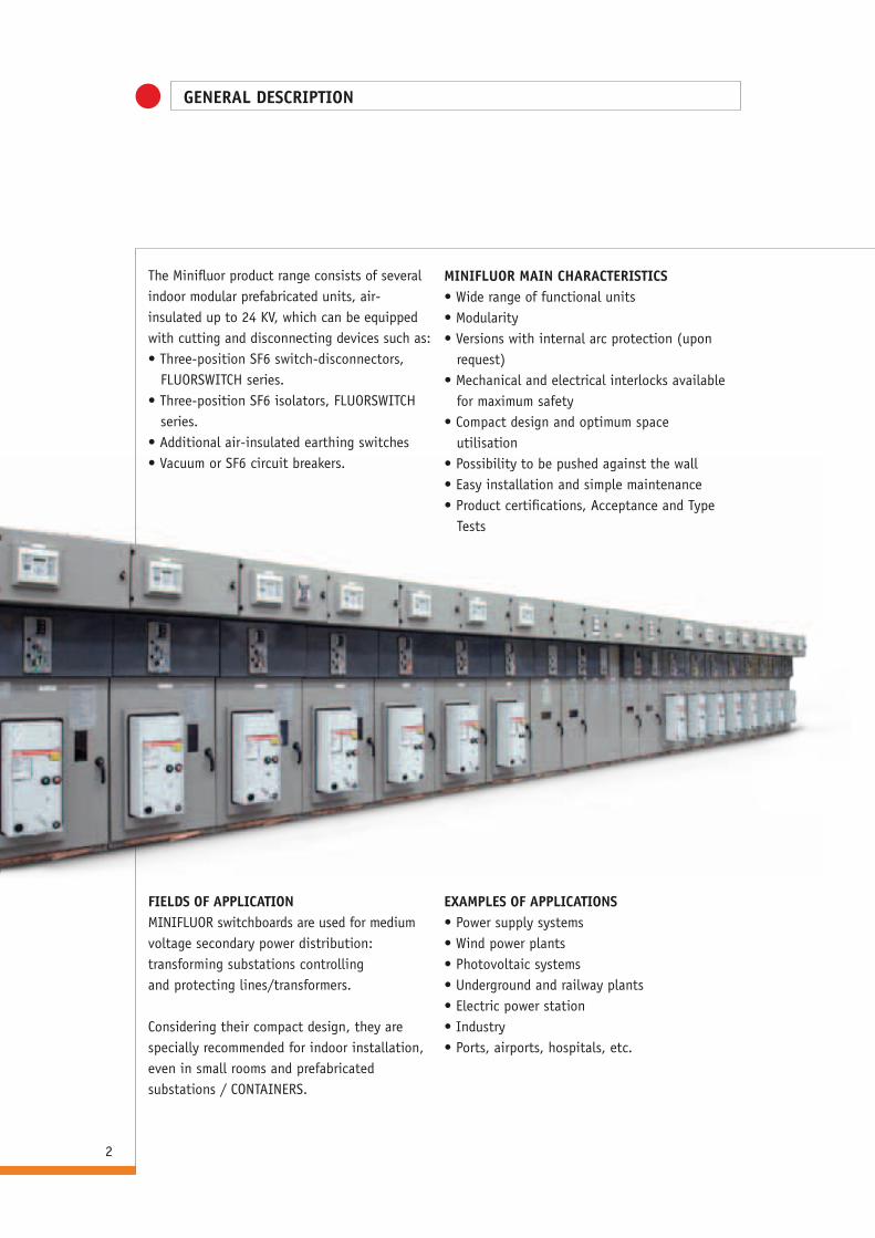
The Minifluor product range consists of several indoor modular prefabricated units, air-insulated up to 24 KV, which can be equipped with cutting and disconnecting devices such as:• Three-position SF6 switch-disconnectors,
FLUORSWITCH series.• Three-position SF6 isolators, FLUORSWITCH
series.• Additional air-insulated earthing switches • Vacuum or SF6 circuit breakers.
MINIFLUOR MAIN CHARACTERISTICS• Wide range of functional units• Modularity• Versions with internal arc protection (upon
request)• Mechanical and electrical interlocks available
for maximum safety• Compact design and optimum space
utilisation• Possibility to be pushed against the wall• Easy installation and simple maintenance • Product certifications, Acceptance and Type
Tests
ExAMPLES OF APPLICATIONS• Power supply systems• Wind power plants• Photovoltaic systems• Underground and railway plants• Electric power station• Industry• Ports, airports, hospitals, etc.
FIELDS OF APPLICATIONMINIFLUOR switchboards are used for medium voltage secondary power distribution: transforming substations controllingand protecting lines/transformers.
Considering their compact design, they are specially recommended for indoor installation, even in small rooms and prefabricated substations / CONTAINERS.
DESCRIPTION
3
STANDARDSThe equipment complies with the following standards:• CEI EN 62271-200• IEC 62271-200More specifically, Minifluor switchboards are classified as follows:• Service continuity: LSC2A• Classification of partitions: PM• Internal arc: IAC AFLR (upon request only)
SAFETY EqUIPMENT • Power supply continuity of the metal structure• Earthing of both structure and parts• Interlocks preventing a wrong operation
sequence:- Switch-disconnector or line-side isolator
closure allowed only with open earthing switch and closed MV door.
- Earthing switch closure allowed only with open switch-disconnector or line-side isolator.
- MV door opening for accessing the line compartment allowed only with closed earthing switch.
- In units with circuit breaker, line-side isolator opening and closure is allowed only with open circuit breaker.
(with key interlock)• Key locks or prearrangement for padlock
installation on isolators (upon request)• Voltage detection by means of galvanically
isolated opto-electrical transducers • Switch-disconnector and line-side isolator
with a single three-position moving contact with independent operation (line closed –
line/earth open - earth closed) with isolation safety guaranteed by:- “Safe position indicator” directly fitted on
the moving contact shaft and compliant with the standards CEI EN 62271-102, IEC
60694 and IEC73- Visible isolation thanks to a special window
(upon request) - Electric contacts for status indication (upon
request)• Versions with internal arc protection (upon
request).
CONDIzIONI DI SERVIzIO • Ambient temperature
- between -5°C and + 40°C• Altitude
- 1000 m or lower - For higher altitude, please contact IMESA
• Environment:- Normal atmosphere, no particles, flammable
gases, corrosive components• Humidity
- Maximum relative humidity without condensation: 95%
STORAGE CONDITIONS For the proper storage of the functional units, keep them wrapped in the original packaging and store in a dry place, protected from rain and sun, at a temperature between -5°C and + 45°C.
AVAILABLE VERSIONS• Standard• Internal arc withstanding classification IAC
AFLR 16KA x 1 s (upon request only)
PROTECTION RATINGSSwitchboard protection ratings refer to IEC 60694 standards.The MINIFLUOR range is generally manufactured with the following protection ratings:• IP3X on the external housing (operation seats excluded)• IP2X inside the unitsExternal housing protection ratings higher than IP3X are available upon request.

INTERNAL ARC PROTECTION
4
In the Minifluor switchboards with internal arc proof design IAC AFLR all functional units are equipped with flaps that open due to the overpressure caused by the internal arc and, thus, make the gas and any possible burning particles to be channelled into a rear venting pipe (large 90mm) so to avoid damages to persons, in compliance with the IEC 62271-200 standard, class A accessibility, criteria 1 to 5.
In order to guarantee all the above, panels are to be installed according to the abovementioned standard (see paragraph “INSTALLATION ROOM”, page 35).
Arc detectors Upon request, Minifluor switchboards can be equipped with various types of sensors that,if properly located on the functional unitsof the switchboard, immediately detect the fault and selectively open the circuit breakers.Their efficacy mainly consists in the prompt detection and fixing of the fault in a very short time, thus reducing fault occurrenceon the equipment, as well as limiting damages.

5
Electrical characteristics
ELECTRICAL AND MANUFACTURING CHARACTERISTICS
Rated voltage Ur [kV] 12 17,5 24
Value of nominal isolation at operating frequency
• between the phases and to ground Ud [kV] 28 38 50
• between open contacts Ud [kV] 32 45 60
Rated lightning impulse withstand voltage
• between the phases and to ground Ud [kV] 75 95 125
• between open contacts Up [kV] 85 110 145
Rated frequency Hz 50/60
Nominal thermal current of main busbars Ir [A] 400-630-800-1250
Rated short-time current allowed
• for 1 s Ik [kA] 12,5-16-20
• for 3 s Ik [kA] 12,5-16
Rated peak current Ip [kA] 31,5-40-50
Internal arc withstand current 1 s (IAC AFLR upon request) [kA] 16
Gas pressure (at 20°) of the switch-disconnector/line-side isolator psw [MPA] 0,13
ELECTRICAL AND MANUFACTURING CHARACTERISTICS
6
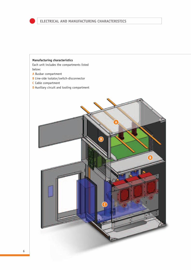
Manufacturing characteristicsEach unit includes the compartments listed below:A Busbar compartmentB Line-side isolator/switch-disconnectorC Cable compartmentD Auxiliary circuit and tooling compartment
A
B
C
D
ELECTRICAL AND MANUFACTURING CHARACTERISTICS
7
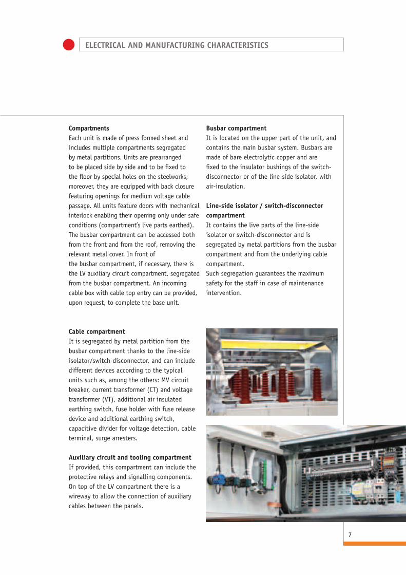
CompartmentsEach unit is made of press formed sheet and includes multiple compartments segregated by metal partitions. Units are prearranged to be placed side by side and to be fixed to the floor by special holes on the steelworks; moreover, they are equipped with back closure featuring openings for medium voltage cable passage. All units feature doors with mechanical interlock enabling their opening only under safe conditions (compartment’s live parts earthed).The busbar compartment can be accessed both from the front and from the roof, removing the relevant metal cover. In front of the busbar compartment, if necessary, there is the LV auxiliary circuit compartment, segregated from the busbar compartment. An incoming cable box with cable top entry can be provided, upon request, to complete the base unit.
Busbar compartmentIt is located on the upper part of the unit, and contains the main busbar system. Busbars are made of bare electrolytic copper and are fixed to the insulator bushings of the switch-disconnector or of the line-side isolator, with air-insulation.
Line-side isolator / switch-disconnector compartmentIt contains the live parts of the line-side isolator or switch-disconnector and is segregated by metal partitions from the busbar compartment and from the underlying cable compartment.Such segregation guarantees the maximum safety for the staff in case of maintenance intervention.
Cable compartmentIt is segregated by metal partition from the busbar compartment thanks to the line-side isolator/switch-disconnector, and can include different devices according to the typical units such as, among the others: MV circuit breaker, current transformer (CT) and voltage transformer (VT), additional air insulated earthing switch, fuse holder with fuse release device and additional earthing switch, capacitive divider for voltage detection, cable terminal, surge arresters.
Auxiliary circuit and tooling compartmentIf provided, this compartment can include the protective relays and signalling components.On top of the LV compartment there is a wireway to allow the connection of auxiliary cables between the panels.

MAIN PARTS
8
FLUORSWITCH DISCONNECTORS AND ISOLATORS
General InformationFLUORSWITCH disconnectors and isolators are characterised by the use of sulphur hexafluoride (SF6) for disconnection and isolation.Basically, they consist of a stainless steel housing sealed for life and containing SF6 at a pressure of 0.13 MPa at a temperature of 20°C). Inside the housing there are the contacts (fixed, moving and earthing), the arcing chambers and the mechanisms for transferring movement to the moving contact themselves. External electrical connections are made by means of epoxy resin insulator bushings. Fluorswitch devices include: switch-disconnectors and earthing switches (IMS6), equipped with (manual and/or motor operated) operating mechanisms with independent operation of the over dead centre type and with stored energy; combined disconnectors/earthing switches (SLT6); SF6 insulated line-side isolators (SL6) and earthing switches (ST6) equipped with manual operating mechanism with dependent operation.
Three stable positions are possible for these devices: Line Closed - Line/Earth Open - Earth Closed.• In the Line Closed position the device
guarantees the electrical connection between the input and output of each pole, on
insulator bushing end (pic.1)• In the Line/Earth Open position the device
guarantees the isolation between fixed and moving contacts, on both line and
earth (pic.2).• In the Earth Closed position, the line on
device load side is earthed (Pic.3).
Pic. 1 Pic. 2 Pic. 3
Main contacts and commandsOn the operating mechanism front plate there are the
mechanical position indicators (open/close) of the two combined devices, whereas for the stored energy operating mechanism there is also a mechanical indicator of fuse activation. Upon request, a special inspection window can be installed on the front of the enclosure
Upon request, the operating mechanisms can be equipped with key locks and device electric status signalling.
Moreover, the advantages of these devices are:• No maintenance required for live parts;• Safe operation: single contact moving shaft for both line
and earth;• Long lasting electrical and mechanical life (high operation
frequency type);• No leakage current is allowed to flow between input and
output, since the metal housing is properly earthed.
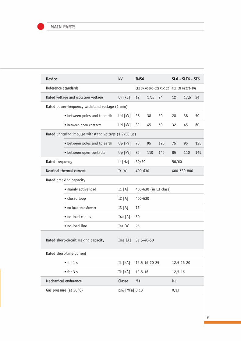
Device kV IMS6 SL6 - SLT6 - ST6
Reference standards CEI EN 60265-62271-102 CEI EN 62271-102
Rated voltage and isolation voltage Ur [kV] 12 17,5 24 12 17,5 24
Rated power-frequency withstand voltage (1 min)
• between poles and to earth Ud [kV] 28 38 50 28 38 50
• between open contacts Ud [kV] 32 45 60 32 45 60
Rated lightning impulse withstand voltage (1.2/50 ms)
• between poles and to earth Up [kV] 75 95 125 75 95 125
• between open contacts Up [kV] 85 110 145 85 110 145
Rated frequency fr [Hz] 50/60 50/60
Nominal thermal current Ir [A] 400-630 400-630-800
Rated breaking capacity
• mainly active load I1 [A] 400-630 (in E3 class)
• closed loop I2 [A] 400-630
• no-load transformer I3 [A] 16
• no-load cables I4a [A] 50
• no-load line Isa [A] 25
Rated short-circuit making capacity Ima [A] 31,5-40-50
Rated short-time current
• for 1 s Ik [KA] 12,5-16-20-25 12,5-16-20
• for 3 s Ik [KA] 12,5-16 12,5-16
Mechanical endurance Classe M1 M1
Gas pressure (at 20°C) psw [MPa] 0,13 0,13
MAIN PARTS
9Pic. 3

MAIN PARTS
10
Guide to operating mechanism selection• C1: manual operating mechanism with
independent operation of the over dead centre type for opening and closing the
switch-disconnector and the IMS6 type earthing switch.
• C1M: the same as C1, but with motor operated switch-disconnector opening and closing.
• C2: manual operating mechanism with independent operation of the over dead centre type with stored energy for IMS6 type isolator opening, in which the opening can be carried out by fuse activation by means of the proper manual lever and/or remotely by the opening coil.
• C2M: the same as C2, but with motor operated closing and spring charging for energy storage.
• M1: manual operating mechanism with dependent operation for opening the line-side isolator and/or the earthing switch, SLT6, ST6, SL6 type (an additional earthing switch can also be operated at the same time, if equipped).
• M2: manual operating mechanism with dependent operation for the simultaneous opening and closing of two combined disconnectors/earthing switches, SLT6 type, fitted side by side into the same unit.
Air-insulated earthing switchesAir insulated earthing switches are operated (by the C1/C2/M1/M2 operating mechanisms) simultaneously to the SF6 insulated earthing switch being inside the IMS6 and SLT6 tank. The air insulated earthing switches for PT and PTX compartments feature a peak making capacity >=2.5KA at 24 KV. Upon request, the compartments with circuit breaker and additional air insulated earthing switch can be equipped with earthing switch with 40KA peak making capacity.
Electrical characteristics
Tipo Short-time Making short circuit current for 1” capacity
STx2,5 1KA 2,5KA*
ST2,5 1KA 2,5KA*
ST 12,5-16KA -
ST40 12,5-16KA 31,5-40KA*
* 2 locks

TYPICAL UNITS
11
KEY TO SYMBOLS for selectingthe compartments and properly understanding the tablesCompartment nameA Incoming unit PT Transformer protectionP Outgoing unitM InstrumentC Bus tieL Improved version L 750 mmR Busbar riserx Reduced version L 375 mmB Circuit breaker First suffix (e.g. CR - z - D)I IMS switch-disconnectorz SLT combined disconnector/earthing switch
Second subsequent suffix (e.g. CD - S - D)S LeftD Right
l basic equipmentm additional equipment upon request- not availableNB the anti-condensation heater, if requested,
will always be located in the incoming cable compartment.

TYPICAL UNITS
12
EqUIPMENT OF STANDARDISED COMPARTMENTS
AP-I l - - - - - - l m - - m m m m m m l m m l m
APx-I l - - - - - - l m - - m - m m m m l m m l m
AP-z - l - - - - - - - l - m m m m m m l m m l m
APx-z - l - - - - - - - l - m - m m m m l m m l m
A - - - - - - l - - l - m m m m m m l m m l m
Ax - - l - - - - - - l - m - m m m m l m m l m
APB - l - - - l l - - l - m m m m m m l m m l m
APBR - l - - - l l - - l - m m m m m m l m m l l
CRB-S - l l - - l - - - - l m m m m m m l m m l m
CRB-D - l l - - l - - - - l m m m m m m l m m l m
CRB2 - lx2 - - - l - - - - l m m m m m m l m m l m
PT l - - - - - l - l - - m m m m m m l m m l m
PTx l - - - - - l - l - - m - m m m m l m m l m
CR-I-S l - - - l - - l m - - m m m m m m l m m l m
CR-I-D l - - - l - - l m - - m m m m m m l m m l m
CR-z-S - l - - l - - - - l - m m m m m m l m m l m
CR-z-D - l - - l - - - - l - m m m m m m l m m l m
CR2 - lx2 - - - - - - - - l m m m m m m l m m l m
APM l - - - - - l - - - - m m m m m m l m m l m
APMF l - - - - - l - - - - m m m m m m l m m l m
M-I l - - - - - m - l - - m m m m m m l m m l m
M-z - l - - - - m - - l - m m m m m m l m m l m
ML-I l - - - - - m - l - - m m m m m m l m m l m
AR - - - - - - - - - - - - m m m m m - m m - m
ARx - - - - - - - - - - - - m m m m m - m m - m
RW-S - - - - - - - - - - - - - - - m m - m m - m
RW-D - - - - - - - - - - - - - - - m m - m m - m
CC-S - - - - - - - - - - - - - - - m m - - - - m
CC-D - - - - - - - - - - - - - - - m m - - - - m
IMS6
SLT6
ST6
SL6
P6 CIRC
UIT
BREA
KER
AIR
INSU
LATE
D EA
RTHI
NG S
WIT
CH
C1/C
1M
C2/C
2M
M1
M2
VERS
IONS
WIT
H IN
TERN
AL
ARC
PROT
ECTI
ON
INTE
RNAL
LIG
HTIN
G
ANTI
-CON
DENS
ATIO
N HE
ATER
W
ITH
THER
MOS
TAT
INCO
MIN
G CA
BLE
BOx
WIT
H TO
P EN
TRY
BASE
H 3
00 m
m
BASE
H 4
00 m
m
STAN
DARD
LV
COM
PART
MEN
T
LV C
OMPA
RTM
ENT
- DE
PTH
18
0 m
m
LV C
OMPA
RTM
ENT
- DE
PTH
30
0 m
m
SET
OF T
HREE
LIN
E SI
DE
CAPA
CITI
VE I
SOLA
TORS
SET
OF T
HREE
BUS
BAR
SIDE
CA
PACI
TIVE
ISO
LATO
RS
DEVICES DEVICES OTHER ACCESSORIES
TYPICAL UNITS
13
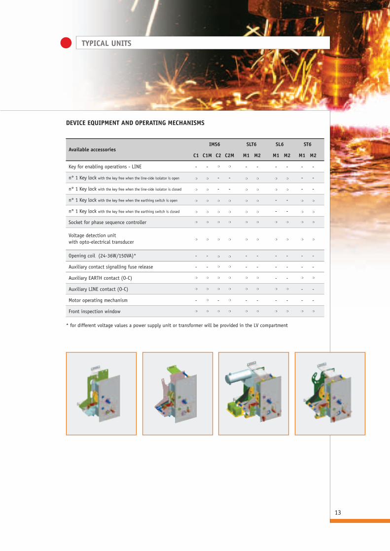
DEVICE EqUIPMENT AND OPERATING MECHANISMS
Available accessories IMS6 SLT6 SL6 ST6
C1 C1M C2 C2M M1 M2 M1 M2 M1 M2
Key for enabling operations - LINE - - m m - - - - - -
n° 1 Key lock with the key free when the line-side isolator is open m m - - m m m m - -
n° 1 Key lock with the key free when the line-side isolator is closed m m - - m m m m - -
n° 1 Key lock with the key free when the earthing switch is open m m m m m m - - m m
n° 1 Key lock with the key free when the earthing switch is closed m m m m m m - - m m
Socket for phase sequence controller m m m m m m m m m m
Voltage detection unit m m m m m m m m m m
with opto-electrical transducer
Opening coil (24-36W/150VA)* - - m m - - - - - -
Auxiliary contact signalling fuse release - - m m - - - - - -
Auxiliary EARTH contact (O-C) m m m m m m - - m m
Auxiliary LINE contact (O-C) m m m m m m m m - -
Motor operating mechanism - m - m - - - - - -
Front inspection window m m m m m m m m m m
* for different voltage values a power supply unit or transformer will be provided in the LV compartment

TYPICAL UNITS
14
AP-I and APx-I UNITSwith switch-disconnector
1850
1850
500 375
Basic configuration• Switch-disconnector and earthing switch
IMS6 with C1/C1M, C2/C2M operating mechanism.
• Door lock• Busbar system and earthing circuit• Cable terminal• Back plate for cable anchoring
Electrical characteristics• Ir 400-630 A• Ik 12.5-16-20 kA
AP-I APx-I Notes
Through-type CT - -
Toroidal phase CT m m
Homopolar toroid CT m m
Phase-to-phase VT - -
Phase-to-earth VT - -
Medium voltage surge arresters m -
MV surge arrester release device m - *
MV surge arrester impulse counter m - *
* Upon request, the incoming/outgoing cable unit can be excluded from the compartment. It is not possible to install both devices.
Medium voltage parts to be provided upon request for completing the base unit
AP-I APx-I

TYPICAL UNITS
15
AP-z and APx-z UNITwith combined disconnector/earthing switch
1850
1850
500 375
Basic configuration• Combined disconnector/earthing switch SLT6 with M1 operating mechanism• Door lock• Busbar system and earthing circuit• Cable terminal• Back plate for cable anchoring
Electrical characteristics• Ir 400-630-800 A• Ik 12.5-16-20 kA
AP-z APz-x Notes
Through-type CT - -
Toroidal phase CT m m
Homopolar toroid CT m m
Phase-to-phase VT - -
Phase-to-earth VT - -
Medium voltage surge arresters m -
MV surge arrester release device m - *
MV surge arrester impulse counter m - *
* Upon request, the incoming/outgoing cable unit can be excluded from the compartment. It is not possible to install both devices.
Medium voltage parts to be provided upon request for completing the base unit
AP-z APx-z
1850
1850
500 375
TYPICAL UNITS
16
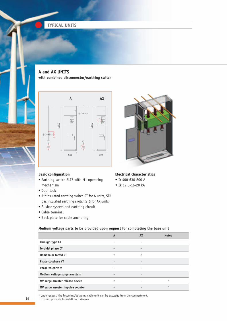
A and Ax UNITSwith combined disconnector/earthing switch
Basic configuration• Earthing switch SLT6 with M1 operating
mechanism• Door lock• Air insulated earthing switch ST for A units, SF6
gas insulated earthing switch ST6 for AX units• Busbar system and earthing circuit• Cable terminal• Back plate for cable anchoring
Electrical characteristics• Ir 400-630-800 A• Ik 12.5-16-20 kA
A Ax Notes
Through-type CT - -
Toroidal phase CT m m
Homopolar toroid CT m m
Phase-to-phase VT - -
Phase-to-earth V - -
Medium voltage surge arresters m -
MV surge arrester release device m - *
MV surge arrester impulse counter m - *
* Upon request, the incoming/outgoing cable unit can be excluded from the compartment. It is not possible to install both devices.
Medium voltage parts to be provided upon request for completing the base unit
A Ax

TYPICAL UNITS
17
APB UNITincoming/outgoing unit with combined disconnector/earthing switch and circuit breaker
1850
750
Basic configuration• Combined disconnector/earthing switch SLT6
with M1 operating mechanism, two combined disconnectors/earthing switches SLT6 with M2 operating mechanism for the 1250 A version.
• Vacuum or SF6 circuit breaker. • Additional air-insulated earthing switch ST• Mechanical interlock between the circuit breaker
and the combined disconnector/earthing switch
• Door lock• Busbar system and earthing circuit• Cable terminal• Back plate for cable anchoring
Electrical characteristics• Ir 400-630-800-1250 A• Ik 12.5-16-20 kA
APB APB1250 Notes
2/3 pcs through-type CT mmm- - - m- -
Toroidal phase CT mmmmm mmmm
Homopolar toroid CT mmmmm mmmm
2 pcs phase-to-phase VT --m- - m -- m
3 pcs phase-to-earth VT -m-m - - -m -
Current sensor on board the circuit breaker ---m m - -m m
Medium voltage surge arresters m--- m m m- -
MV surge arrester release device ---- - - -- -
MV surge arrester impulse counter ---- - - -- -
The table shows the possible configurations (right to left) when completing the base unitwith several accessories at the same time (top to bottom)
Medium voltage parts to be provided upon request for completing the base unit
TYPICAL UNITS
18
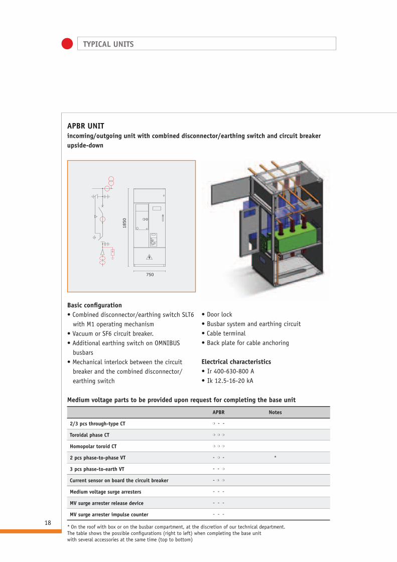
APBR UNITincoming/outgoing unit with combined disconnector/earthing switch and circuit breaker upside-down
1850
750
Basic configuration• Combined disconnector/earthing switch SLT6
with M1 operating mechanism• Vacuum or SF6 circuit breaker. • Additional earthing switch on OMNIBUS
busbars• Mechanical interlock between the circuit
breaker and the combined disconnector/earthing switch
• Door lock• Busbar system and earthing circuit• Cable terminal• Back plate for cable anchoring
Electrical characteristics• Ir 400-630-800 A• Ik 12.5-16-20 kA
APBR Notes
2/3 pcs through-type CT m- -
Toroidal phase CT mmm
Homopolar toroid CT mmm
2 pcs phase-to-phase VT -m- *
3 pcs phase-to-earth VT - -m
Current sensor on board the circuit breaker -m m
Medium voltage surge arresters ---
MV surge arrester release device ---
MV surge arrester impulse counter ---
Medium voltage parts to be provided upon request for completing the base unit
* On the roof with box or on the busbar compartment, at the discretion of our technical department.The table shows the possible configurations (right to left) when completing the base unitwith several accessories at the same time (top to bottom)
TYPICAL UNITS
19
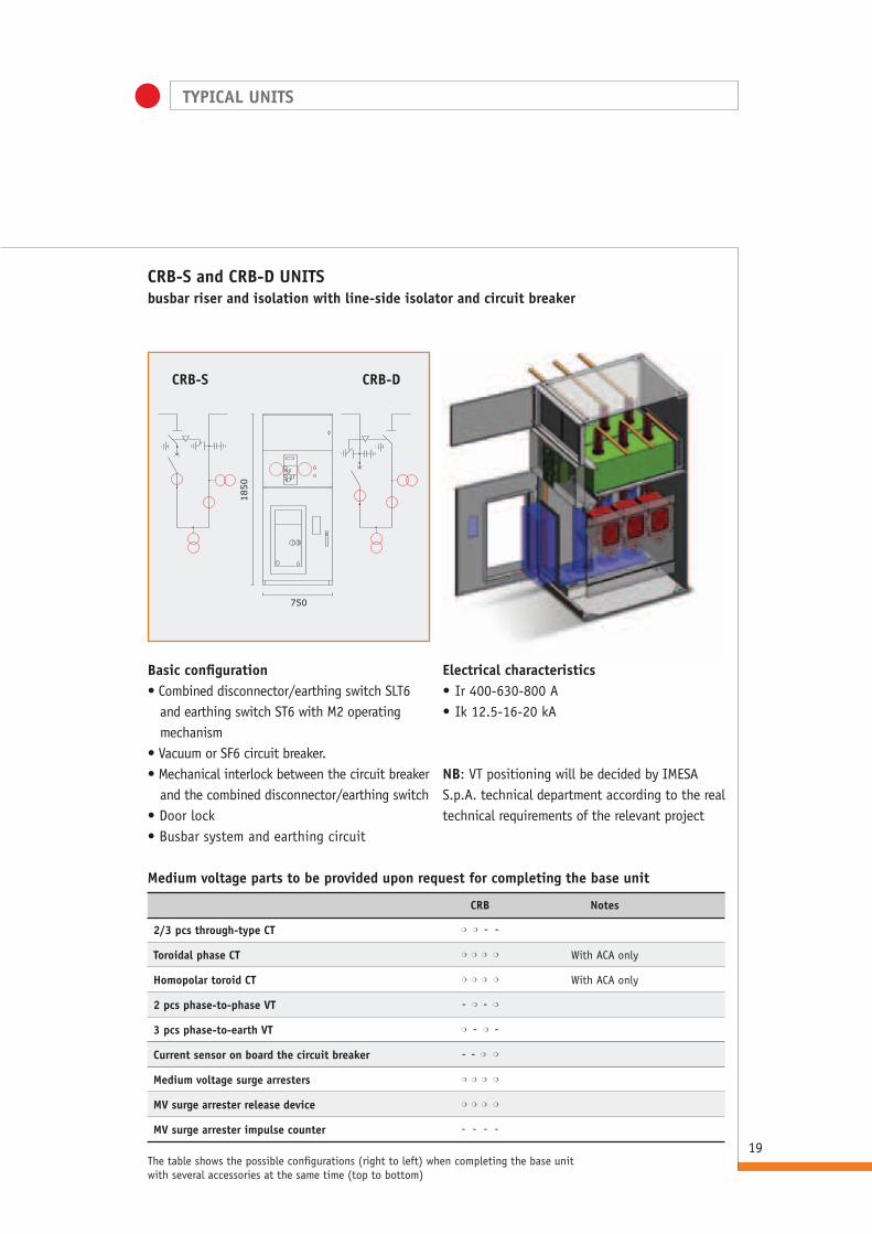
CRB-S and CRB-D UNITS busbar riser and isolation with line-side isolator and circuit breaker
1850
750
Basic configuration• Combined disconnector/earthing switch SLT6
and earthing switch ST6 with M2 operating mechanism
• Vacuum or SF6 circuit breaker. • Mechanical interlock between the circuit breaker
and the combined disconnector/earthing switch • Door lock• Busbar system and earthing circuit
Electrical characteristics• Ir 400-630-800 A• Ik 12.5-16-20 kA
CRB Notes
2/3 pcs through-type CT mm- -
Toroidal phase CT mmmm With ACA only
Homopolar toroid CT mmmm With ACA only
2 pcs phase-to-phase VT -m-m
3 pcs phase-to-earth VT m- m-
Current sensor on board the circuit breaker --m m
Medium voltage surge arresters mmmm
MV surge arrester release device mmmm
MV surge arrester impulse counter ----
Medium voltage parts to be provided upon request for completing the base unit
NB: VT positioning will be decided by IMESA S.p.A. technical department according to the real technical requirements of the relevant project
The table shows the possible configurations (right to left) when completing the base unitwith several accessories at the same time (top to bottom)
CRB-S CRB-D
TYPICAL UNITS
20
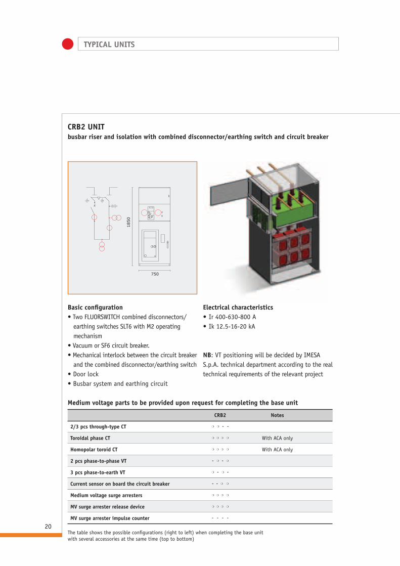
CRB2 UNIT busbar riser and isolation with combined disconnector/earthing switch and circuit breaker
1850
750
Basic configuration• Two FLUORSWITCH combined disconnectors/
earthing switches SLT6 with M2 operating mechanism
• Vacuum or SF6 circuit breaker. • Mechanical interlock between the circuit breaker
and the combined disconnector/earthing switch • Door lock• Busbar system and earthing circuit
Electrical characteristics• Ir 400-630-800 A• Ik 12.5-16-20 kA
CRB2 Notes
2/3 pcs through-type CT mm- -
Toroidal phase CT mmmm With ACA only
Homopolar toroid CT mmmm With ACA only
2 pcs phase-to-phase VT -m-m
3 pcs phase-to-earth VT m- m-
Current sensor on board the circuit breaker --m m
Medium voltage surge arresters mmmm
MV surge arrester release device mmmm
MV surge arrester impulse counter ----
Medium voltage parts to be provided upon request for completing the base unit
NB: VT positioning will be decided by IMESA S.p.A. technical department according to the real technical requirements of the relevant project
The table shows the possible configurations (right to left) when completing the base unitwith several accessories at the same time (top to bottom)
TYPICAL UNITS
21
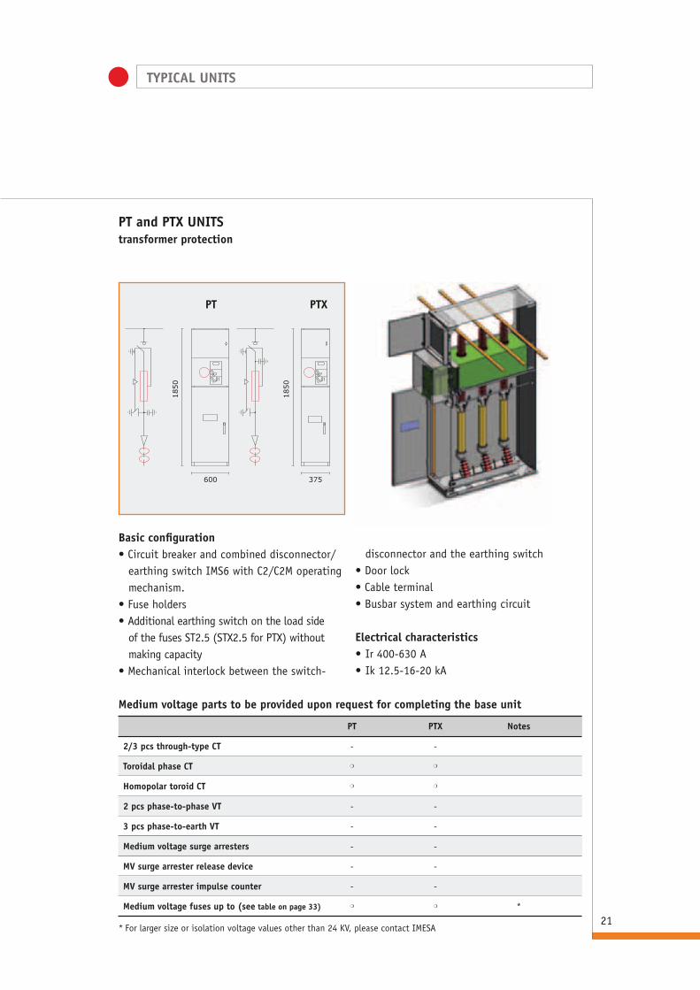
PT and PTx UNITS transformer protection
1850
1850
600 375
Basic configuration• Circuit breaker and combined disconnector/
earthing switch IMS6 with C2/C2M operating mechanism.
• Fuse holders• Additional earthing switch on the load side
of the fuses ST2.5 (STX2.5 for PTX) without making capacity
• Mechanical interlock between the switch-
disconnector and the earthing switch • Door lock• Cable terminal• Busbar system and earthing circuit
Electrical characteristics• Ir 400-630 A• Ik 12.5-16-20 kA
PT PTx Notes
2/3 pcs through-type CT - -
Toroidal phase CT m m
Homopolar toroid CT m m
2 pcs phase-to-phase VT - -
3 pcs phase-to-earth VT - -
Medium voltage surge arresters - -
MV surge arrester release device - -
MV surge arrester impulse counter - -
Medium voltage fuses up to (see table on page 33) m m *
* For larger size or isolation voltage values other than 24 KV, please contact IMESA
Medium voltage parts to be provided upon request for completing the base unit
PT PTx

TYPICAL UNITS
22
CR-I-S and CR-I-D UNITS busbar isolation with switch-disconnector
1850
750
Basic configuration• Switch-disconnector and earthing switch
IMS6 with C1 or C1M, C2 or C2M operating mechanism.
• Bolted door • Busbar system and earthing circuit• Back plate
Electrical characteristics• Ir 400-630 A• Ik 12.5-16-20 kA
CR-I Notes
2/3 pcs through-type CT mm-
Toroidal phase CT mmm With ACA only
Homopolar toroid CT mmm With ACA only
2 pcs phase-to-phase VT -mm
3 pcs phase-to-earth VT m- m
Medium voltage surge arresters mmm
MV surge arrester release device mmm *
MV surge arrester impulse counter mmm *
Medium voltage parts to be provided upon request for completing the base unit
* It is not possible to install both devices.The table shows the possible configurations (right to left) when completing the base unitwith several accessories at the same time (top to bottom)
NB: VT positioning will be decided by IMESA S.p.A. technical department.
CR-I-S CR-I-D

23
CR-z-S and CR- z-D UNITS busbar isolation with combined disconnector/earthing switch
1850
750
Basic configuration• Combined disconnector/earthing switch SLT6
with M1 operating mechanism• Bolted door • Busbar system and earthing circuit• Back plate
Electrical characteristics• Ir 400-630 A• Ik 12.5-16-20 kA
CR-z Notes
2/3 pcs through-type CT mm-
Toroidal phase CT mmm With ACA only
Homopolar toroid CT mmm With ACA only
2 pcs phase-to-phase VT -mm
3 pcs phase-to-earth VT m- m
Medium voltage surge arresters mmm
MV surge arrester release device mmm *
MV surge arrester impulse counter mmm *
Medium voltage parts to be provided upon request for completing the base unit
NB: VT positioning will be decided by IMESA S.p.A. technical department according to the real technical requirements of the relevant project
* It is not possible to install both devices.The table shows the possible configurations (right to left) when completing the base unitwith several accessories at the same time (top to bottom)
CR-z-S CR-z-D
TYPICAL UNITS

TYPICAL UNITS
24
CR2 UNITbusbar riser and isolation with combined disconnector/earthing switch
1850
750
Basic configuration• Two FLUORSWITCH combined disconnectors/
earthing switches SLT6 with M2 operating mechanism
• Door lock• Busbar system and earthing circuit• Back plate
Electrical characteristics• Ir 400-630-800 A• Ik 12.5-16-20 kA
CR2 Notes
2/3 pcs through-type CT mm-
Toroidal phase CT mmm With ACA only
Homopolar toroid CT mmm With ACA only
2 pcs phase-to-phase VT -mm
3 pcs phase-to-earth VT m- m
Medium voltage surge arresters mmm
MV surge arrester release device mmm *
MV surge arrester impulse counter mmm *
Medium voltage parts to be provided upon request for completing the base unit
NB: VT positioning will be decided by IMESA S.p.A. technical department according to the real technical requirements of the relevant project
* It is not possible to install both devices.The table shows the possible configurations (right to left) when completing the base unitwith several accessories at the same time (top to bottom)
TYPICAL UNITS
25
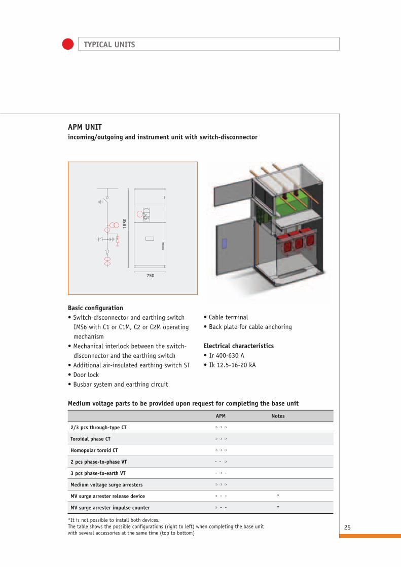
APM UNIT incoming/outgoing and instrument unit with switch-disconnector
1850
750
Basic configuration• Switch-disconnector and earthing switch
IMS6 with C1 or C1M, C2 or C2M operating mechanism
• Mechanical interlock between the switch-disconnector and the earthing switch
• Additional air-insulated earthing switch ST• Door lock• Busbar system and earthing circuit
• Cable terminal• Back plate for cable anchoring
Electrical characteristics• Ir 400-630 A• Ik 12.5-16-20 kA
APM Notes
2/3 pcs through-type CT mmm
Toroidal phase CT mmm
Homopolar toroid CT mmm
2 pcs phase-to-phase VT --m
3 pcs phase-to-earth VT -m-
Medium voltage surge arresters mmm
MV surge arrester release device m-- *
MV surge arrester impulse counter m-- *
Medium voltage parts to be provided upon request for completing the base unit
* It is not possible to install both devices.The table shows the possible configurations (right to left) when completing the base unitwith several accessories at the same time (top to bottom)

TYPICAL UNITS
26
APMF UNITincoming/outgoing unit with fuses and instrument unit with switch-disconnector
1850
750
Basic configuration• Switch-disconnector and earthing switch
IMS6 with C2 or C2M operating mechanism• Mechanical interlock between the switch-
disconnector and the earthing switch • Additional air-insulated earthing switch ST• Door lock• Busbar system and earthing circuit
• Cable terminal• Back plate for cable anchoring
Electrical characteristics• Ir 400-630 A• Ik 12.5-16-20 kA
APMF Notes
2/3 pcs through-type CT mmm
Toroidal phase CT mmm
Homopolar toroid CT mmm
2 pcs phase-to-phase VT --m
3 pcs phase-to-earth VT -m-
2.5 A medium voltage fuses lll
Medium voltage surge arresters mmm
MV surge arrester release device m-- *
MV surge arrester impulse counter m-- *
Medium voltage parts to be provided upon request for completing the base unit
* It is not possible to install both devices.The table shows the possible configurations (right to left) when completing the base unitwith several accessories at the same time (top to bottom)
TYPICAL UNITS
27
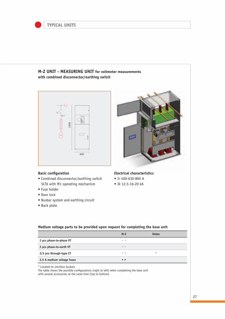
M-z UNIT - MEASURING UNIT for voltmeter measurements with combined disconnector/earthing switch
1850
600
Basic configuration• Combined disconnector/earthing switch SLT6 with M1 operating mechanism• Fuse holder• Door lock• Busbar system and earthing circuit• Back plate
Electrical characteristics• Ir 400-630-800 A• Ik 12.5-16-20 kA
M-z Notes
2 pcs phase-to-phase VT -m
3 pcs phase-to-earth VT m-
2/3 pcs through-type CT mm *
2.5 A medium voltage fuses ll
Medium voltage parts to be provided upon request for completing the base unit
* Located on omnibus busbarsThe table shows the possible configurations (right to left) when completing the base unitwith several accessories at the same time (top to bottom)

28
M-I UNIT - MEASURING UNIT for voltmeter measurements with switch-disconnector
1850
600
Basic configuration• Switch-disconnector and combined
disconnector/earthing switch IMS6 with C2/C2M operating mechanism.
• Fuse holder• Mechanical interlock between the switch-
disconnector and the earthing switch • Door lock
• Busbar system and earthing circuit• Back plate
Electrical characteristics• Ir 400-630 A• Ik 12.5-16-20 kA
M-I Notes
2 pcs phase-to-phase VT -m
3 pcs phase-to-earth VT m-
2/3 pcs through-type CT mm *
2.5 A medium voltage fuses ll
Medium voltage parts to be provided upon request for completing the base unit
* Located on omnibus busbarsThe table shows the possible configurations (right to left) when completing the base unitwith several accessories at the same time (top to bottom)
TYPICAL UNITS
TYPICAL UNITS
29
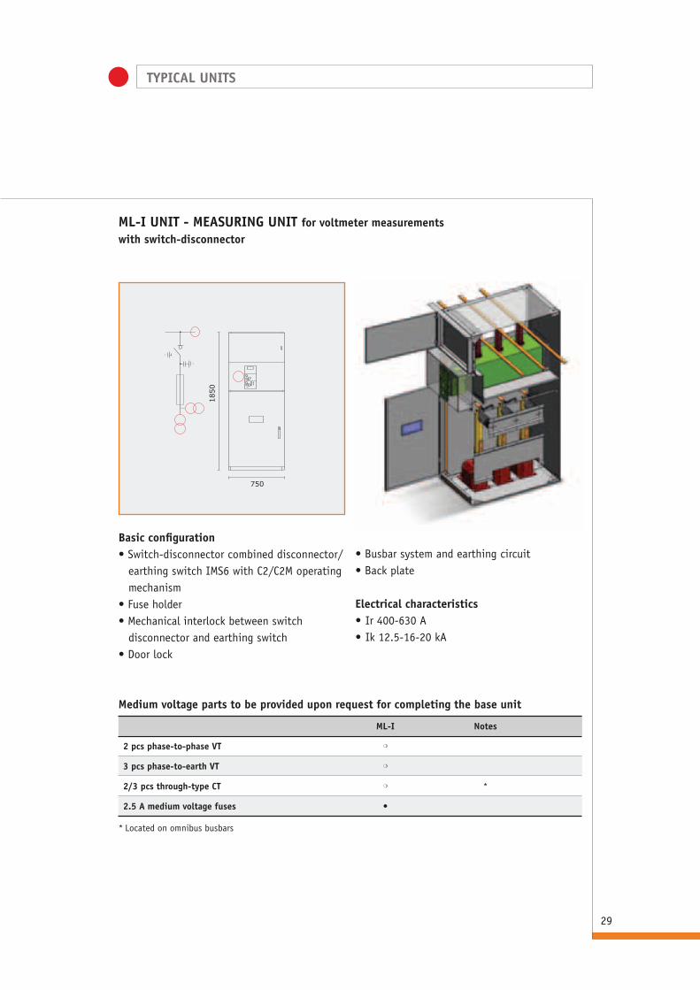
ML-I UNIT - MEASURING UNIT for voltmeter measurementswith switch-disconnector
1850
750
Basic configuration• Switch-disconnector combined disconnector/
earthing switch IMS6 with C2/C2M operating mechanism
• Fuse holder• Mechanical interlock between switch
disconnector and earthing switch• Door lock
• Busbar system and earthing circuit• Back plate
Electrical characteristics• Ir 400-630 A• Ik 12.5-16-20 kA
ML-I Notes
2 pcs phase-to-phase VT m
3 pcs phase-to-earth VT m
2/3 pcs through-type CT m *
2.5 A medium voltage fuses l
Medium voltage parts to be provided upon request for completing the base unit
* Located on omnibus busbars

TYPICAL UNITS
30
AR and ARx UNITS busbar incoming/outgoing unit
RW-S and RW-D UNIT incoming cable, bottom entry
CC-S and CC-D UNITS incoming cable, bottom entry
1850
1850
500 375
250
1850
150
1850
Basic configuration• 3 supporting insulators• Busbar system• Set of three incoming line side capacitive
isolators
Basic configuration• Busbar system• Set of three incoming line side capacitive
isolators fitted on the busbar side of the adjacent compartment
Basic configuration• Busbar system• Set of three incoming line side capacitive isolators fitted on the busbar side of the adjacent compartmentNB: the compartment can be accessed from the side only.Medium voltage parts to be provided upon requestfor completing the base unit
AR ARx
Toroidal phase CT m m
Homopolar toroid CT m m
RW
Toroidal phase CT m
Homopolar toroid CT m*
CC
Toroidal phase CT m*
Homopolar toroid CT m*
Medium voltage parts to be provided upon request for completing the base unit
Medium voltage parts to be provided upon request for completing the base unit
* In the wireway or in the base, if equipped
* In the wireway or in the base, if equipped
AR ARx

TYPICAL UNITS
31
Internal lighting m
AREL SBP1 key lock l
Front earthing busbar l
Accessories provided upon request for completing the base unit
Transformer housing UNITSTransformer housing units are available only in the standard version without internal arc protection. They are made of pre-galvanized sheet, except for the front, which is RAL 7035 painted.
Available UNITS
They are equipped with KITs for their fitting on pallets.Upon request, the dimensions of the transformer housing box can be different from those reported. The standard protection degree is IP2X.For further information, contact our sales office.
Standard box dimensions
Transformer box L1500 P1150 H2250
Transformer box L1500 P1300 H2250
Transformer box L1500 P1150 H2250
Transformer box L1500 P1725 H2250
Transformer box L1500 P2000 H2250
Transformer box L1800 P1150 H2250
Transformer box L1800 P1300 H2250
Transformer box L1800 P1500 H2250
Transformer box L1800 P1725 H2250
Transformer box L1800 P2000 H2250
Transformer box L2000 P1150 H2250
Transformer box L2000 P1300 H2250
Transformer box L2000 P1500 H2250
Transformer box L2000 P1725 H2250
Transformer box L2000 P2000 H2250
Transformer box L2000 P2500 H2250
Transformer box L2500 P2000 H2250
Transformer box L2500 P2000 H2500
Transformer box L2500 P2500 H2500
The transformer housing box shall be selected so to guarantee the compliance with the required insulation distance.
L

COMPARTMENT COMPLETION
32
PaintingOnly front doors will be painted.Painting is carried out by using epoxy powder polymerized in oven at 180° after the surfaces to be painted have undergone washing, degreasing, phosphating, passivating and demineralised water treatments.The standard colour point is RAL 7053 (upon request and against payment of an extra charge different RAL finishings are available).Minimum paint thickness is 60 micron.The bearing structure, the sides and the busbar compartment closing panels are made ofpre-galvanized sheet (upon request and against payment of an extra charge side panels and locks can be painted).
LV compartment for auxiliary circuitsAccording to customer needs, it is possible to install the auxiliary circuit compartment on panel front or top. There, it is possible to place the instruments, protective relays and signalling components.On top of the LV compartment there is a wireway to allow the connection of auxiliary cables between the panels. This wireway is easily accessible by removing the closing plate secured with self-tapping screws (see below).The box is provided with a handle that, upon request, can be equipped with lock.
A 390/540 mmB 70/180/300 mmC 250/375/500/600/750 mm
C
A
B
COMPARTMENT COMPLETION
33
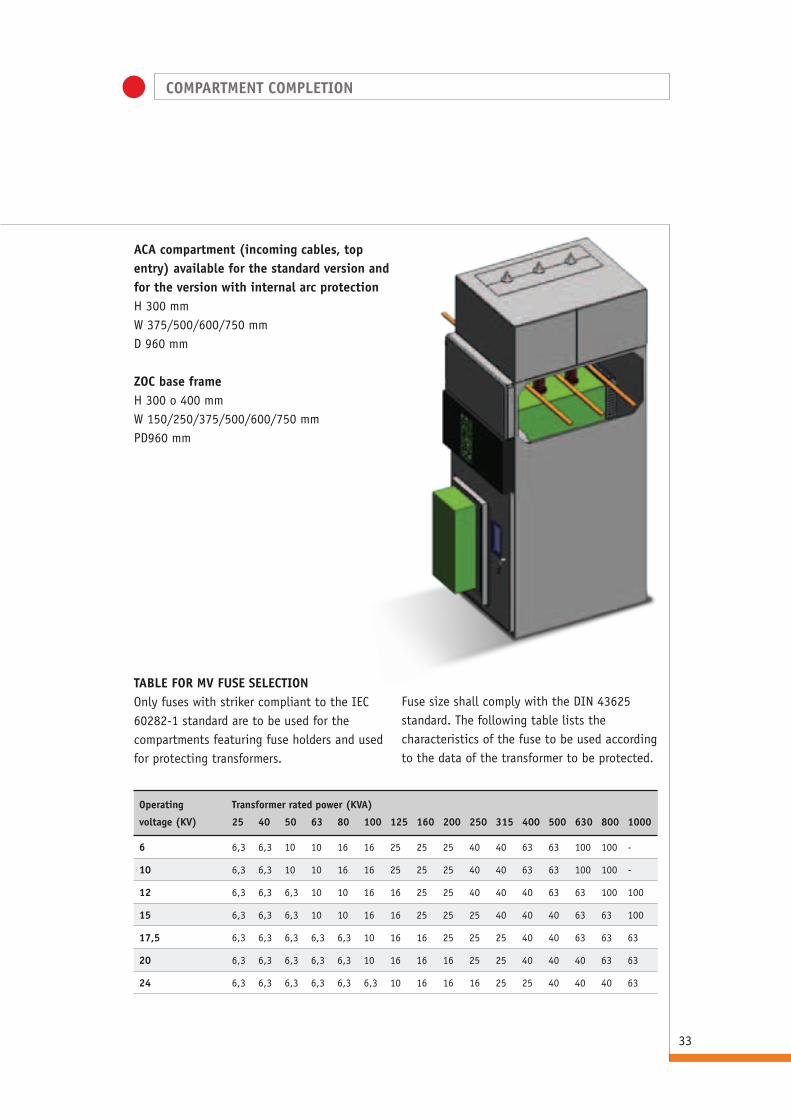
ACA compartment (incoming cables, top entry) available for the standard version and for the version with internal arc protectionH 300 mmW 375/500/600/750 mmD 960 mm
zOC base frameH 300 o 400 mmW 150/250/375/500/600/750 mmPD960 mm
TABLE FOR MV FUSE SELECTION Only fuses with striker compliant to the IEC 60282-1 standard are to be used for the compartments featuring fuse holders and used for protecting transformers.
Fuse size shall comply with the DIN 43625 standard. The following table lists the characteristics of the fuse to be used according to the data of the transformer to be protected.
Operating Transformer rated power (KVA)
voltage (KV) 25 40 50 63 80 100 125 160 200 250 315 400 500 630 800 1000
6 6,3 6,3 10 10 16 16 25 25 25 40 40 63 63 100 100 -
10 6,3 6,3 10 10 16 16 25 25 25 40 40 63 63 100 100 -
12 6,3 6,3 6,3 10 10 16 16 25 25 40 40 40 63 63 100 100
15 6,3 6,3 6,3 10 10 16 16 25 25 25 40 40 40 63 63 100
17,5 6,3 6,3 6,3 6,3 6,3 10 16 16 25 25 25 40 40 63 63 63
20 6,3 6,3 6,3 6,3 6,3 10 16 16 16 25 25 40 40 40 63 63
24 6,3 6,3 6,3 6,3 6,3 6,3 10 16 16 16 25 25 40 40 40 63

INSTALLATION
34
PREPARATION AND FIxING PROCEDUREThe switchboard can be fixed directly to the floor or to special base irons embedded in the floor (provided against payment of an extra charge). Before installing the switchboard, special wireways are to be prearranged to allow cable passing below each unit.Lacking any wireways or floating floor, the base -available among the accessories- hasto be purchased.In all cases, the fixing surface shall bewell levelled.The tentative outline of the foundations (according to the dimensions of the compartment) is reported in the picturesbelow together with the fixing details.
Key to symbols1) Expansion screw2) Plate3) Base iron4) Fixing block
Installationwithout base irons
Installation with base irons (optional)
1
4
2
3
1
2
COMPARTMENTSL 150 mm
COMPARTMENTSL 600 mm without outgoing line
COMPARTMENTSL 750 mm
COMPARTMENTSL 750 mm without outgoing line
COMPARTMENTSL 250 mm
COMPARTMENTSL 375 mm
COMPARTMENTSL 500 mm
COMPARTMENTSL 800 mm
960
960
960
860
860
860
50
500 650 650
150 375 400
250 300
500
460
460
460
250
250
250
460
250
50
50
ø 100
ø 100
ø 100
50 50

35
OVERALL DIMENSIONS
INSTALLATION ROOM The installation room shall be prearranged according to switchboard size and version.The compliance with the height values indicated
will guarantee equipment correct operationShould the conditions of installation differ from what reported, please contact us.
For the version with internal arc protection the minimum height value to be complied with is 600 mm (H1) from compartment roof to room roof, according to what set out by the IEC 62271-200 standard.
H P P1 P2 P3Compartments with circuit breaker 1850 960 1120 1260* +90
Compartments withSLT6/IMS6 1850 960 1050 1260* +90
Version B C DCompartments with circuit breaker ≥50 ≥50 ≥1000*
Compartments with SLT6/IMS6 ≥50 ≥50 ≥1000*
* with 300 mm deep box (Dimensions expressed in mm)
* 1200 with circuit breaker Room dimensions shall be such to allow the access
of one person in order to assemble main busbars. (Dimensions are expressed in mm).
D
B
C
H
H1
PP1
P2
P3
Aux. box
90
37
INSTALLATION

INSTALLATION
36
MEDIUM VOLTAGE CABLE CONNECTION MINIFLUOR compartments are prearranged for the connection of a single-pole cable per medium voltage phase with elastomeric extruded solid insulation (G7 type cables).For the certification, traditional medium voltage eyelet terminal connections areto be provided.Height of the connection point from the floor:
We recommend connecting the terminalsafter positioning the compartments.In case of already existing connections, or connections made before switchboard installation, please contact IMESA technicians to confirm the data reported above.
WHAT IS REPORTED ABOVE SHALL NOT BE CONSIDERED BINDING FOR IMESA S.p.A.
Model A Model A
Ax 800 A 500
APx 800 AP 850
APM and APMF 850*
415**
APB 500
APBR 500
PTx 300 PT 400
ARx 1600 AR 1200
CC 1700 RW 1650
* swithout air-insulated ST
** with air-insulated ST
(Dimensions expressed in mm)
A
A
37
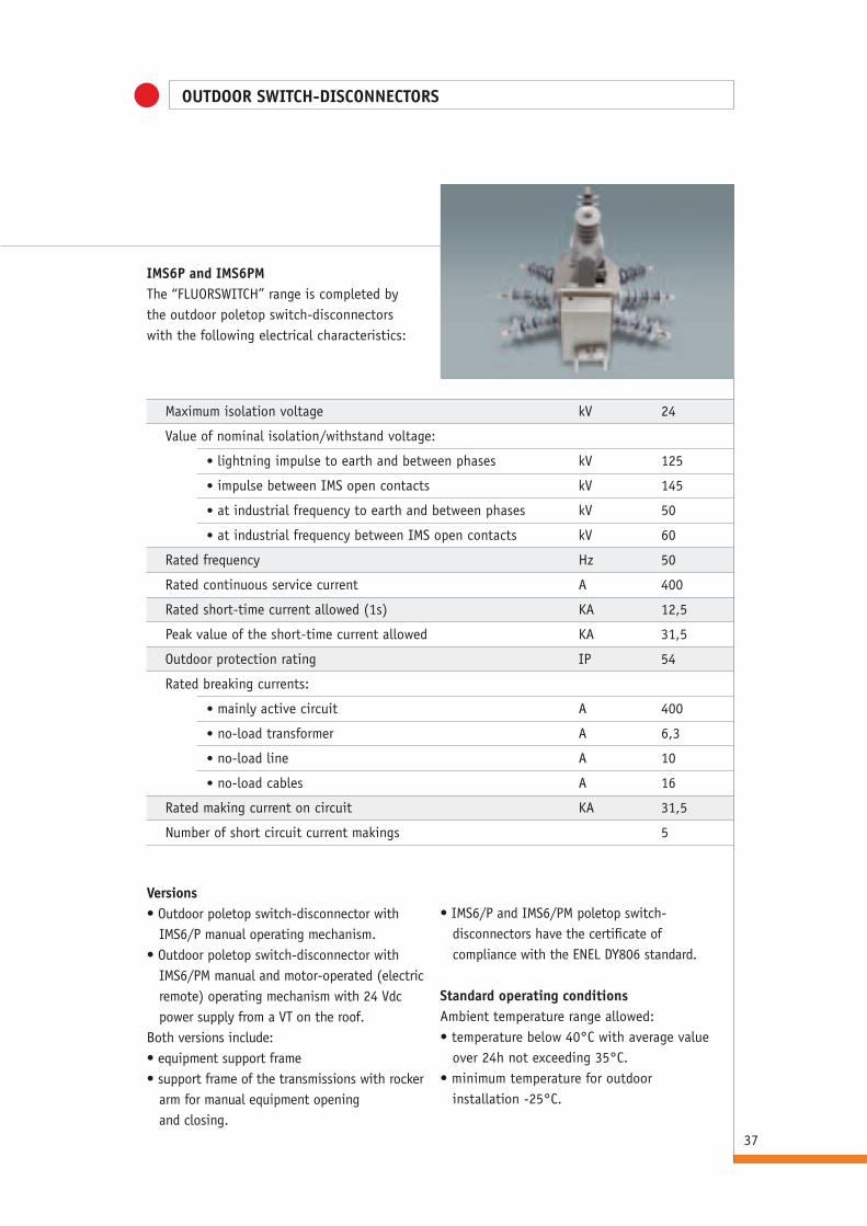
OUTDOOR SWITCH-DISCONNECTORS
• IMS6/P and IMS6/PM poletop switch-disconnectors have the certificate of compliance with the ENEL DY806 standard.
Standard operating conditions Ambient temperature range allowed:• temperature below 40°C with average value
over 24h not exceeding 35°C.• minimum temperature for outdoor
installation -25°C.
Maximum isolation voltage kV 24
Value of nominal isolation/withstand voltage:
• lightning impulse to earth and between phases kV 125
• impulse between IMS open contacts kV 145
• at industrial frequency to earth and between phases kV 50
• at industrial frequency between IMS open contacts kV 60
Rated frequency Hz 50
Rated continuous service current A 400
Rated short-time current allowed (1s) KA 12,5
Peak value of the short-time current allowed KA 31,5
Outdoor protection rating IP 54
Rated breaking currents:
• mainly active circuit A 400
• no-load transformer A 6,3
• no-load line A 10
• no-load cables A 16
Rated making current on circuit KA 31,5
Number of short circuit current makings 5
Versions• Outdoor poletop switch-disconnector with
IMS6/P manual operating mechanism.• Outdoor poletop switch-disconnector with
IMS6/PM manual and motor-operated (electric remote) operating mechanism with 24 Vdc power supply from a VT on the roof.
Both versions include:• equipment support frame• support frame of the transmissions with rocker
arm for manual equipment opening and closing.
IMS6P and IMS6PMThe “FLUORSWITCH” range is completed bythe outdoor poletop switch-disconnectorswith the following electrical characteristics:
38
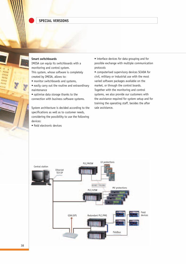
Central stationEthernetTCP/IP
PLC/MVSW
MV protections
Redundant PLC/PMS
Fieldbus
Fielddevices
LV protections
PLC/LVSW
GSM/GPS
Smart switchboardsIMESA can equip its switchboards with a monitoring and control system.This system, whose software is completely created by IMESA, allows to:• monitor switchboards and systems,• easily carry out the routine and extraordinary maintenance• optimise data storage thanks to the connection with business software systems.
System architecture is decided according to the specifications as well as to customer needs, considering the possibility to use the followingdevices:• field electronic devices
• interface devices for data grouping and for possible exchange with multiple communication protocols• computerised supervisory devices SCADA for civil, military or industrial use with the most varied software packages available on the market, or through the control boards.Together with the monitoring and control systems, we also provide our customers with the assistance required for system setup and for training the operating staff, besides the after sale assistance.
SPECIAL VERSIONS
39
SPECIAL VERSIONS
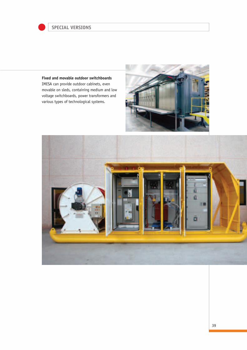
Fixed and movable outdoor switchboardsIMESA can provide outdoor cabinets, even movable on sleds, containing medium and low voltage switchboards, power transformers and various types of technological systems.
CERTIFICATIONS
40
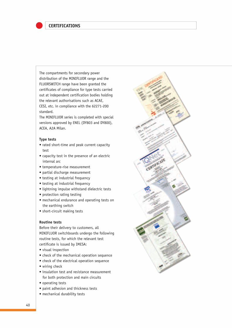
The compartments for secondary power distribution of the MINIFLUOR range and the FLUORSWITCH range have been granted the certificates of compliance for type tests carried out at independent certification bodies holding the relevant authorisations such as ACAE, CESI, etc. in compliance with the 62271-200 standard.The MINIFLUOR series is completed with special versions approved by ENEL (DY803 and DY800), ACEA, A2A Milan.
Type tests • rated short-time and peak current capacity
test• capacity test in the presence of an electric
internal arc• temperature-rise measurement• partial discharge measurement• testing at industrial frequency• testing at industrial frequency• lightning impulse withstand dielectric tests • protection rating testing• mechanical endurance and operating tests on
the earthing switch• short-circuit making tests
Routine testsBefore their delivery to customers, all MINIFLUOR switchboards undergo the following routine tests, for which the relevant test certificate is issued by IMESA:• visual inspection• check of the mechanical operation sequence• check of the electrical operation sequence• wiring check• insulation test and resistance measurement
for both protection and main circuits• operating tests• paint adhesion and thickness tests• mechanical durability tests

HOW TO GET HERE:
By car: from the A14 motorway, “Ancona Nord” exit, take the S.S. 76 clearway to Jesi, exit “Jesi est”, and follow the road signs for “Zona Industriale ZIPA-Jesi”. Our offices are approximately at 1km from the clearway exit.GPS coordinates: 43° 31’ 8” North,13° 14’ 4” East.
By train: the Jesi train station is 2 kmfar from our offices.
By plain: the Ancona-Falconara airportis 12 km far from our offices.
ANCONAJESI
MILANO
BOLOGNA
FIRENZE
VENEZIA
ROMA
NAPOLI
Considering the changes to which the Standards and materials are subject, the characteristics and overall dimensions reported in this catalogue are to be considered as binding only after their confirmation by IMESA SpA.
FABRIANO
PESARO
JESIFABRIANO
ANCONA
FALCONARA
r e g i o n em a r c h e
A14
SS 76
USCITAANCONA
NORD
MACERATA
ASCOLI PICENO
FERMO
URBINO
A14
IMESA SpAvia G. di Vittorio, 14Zona Industriale ZIPA60035 IESI (An) - ITALYtel. +390731211034fax [email protected]
stud
ioco
nti.b
iz 2
012

![Leichtlauf und Ergonomie am Arbeitsplatz. eepos nano · 59,5 cm4 / 16,2 cm4 Widerstandsmomente [Wy/Wz] Moment of resistance [Wy/Wz] 14,9 cm3 / 8,1 cm3 40 Prof il nano 80 prof ile](https://static.fdocuments.us/doc/165x107/5f467cde32940b6e1e7c1321/leichtlauf-und-ergonomie-am-arbeitsplatz-eepos-nano-595-cm4-162-cm4-widerstandsmomente.jpg)