CM - Jauregui - Sapienza University of Rome (60 min, part i, members modified)
41
Graduate Seminar Sapienza University of Rome November 28 th , 2013 Dr. David V Jáuregui Wells-Hatch Professor of Civil Engineering New Mexico State University Las Cruces, NM LOAD RATING of RIVETED STEEL ARCH BRIDGE MEMBERS
-
Upload
franco-bontempi-org-didattica -
Category
Education
-
view
86 -
download
0
Transcript of CM - Jauregui - Sapienza University of Rome (60 min, part i, members modified)

Graduate Seminar
Sapienza University of Rome
November 28th, 2013
Dr. David V Jáuregui
Wells-Hatch Professor of Civil Engineering
New Mexico State University
Las Cruces, NM
LOAD RATING of RIVETED STEEL ARCH BRIDGE MEMBERS

BRIDGE BACKGROUND and DESCRIPTION
AASHTO LOAD RATING ANALYSIS
LOAD RATING of FLOOR SYSTEM
LOAD RATING of COLUMNS
LOAD RATING of ARCH RIB
FINAL LOAD RATING
CONCLUSIONS and RECOMMENDATIONS
OUTLINE of PRESENTATION
BRIDGE BACKGROUND and DESCRIPTION
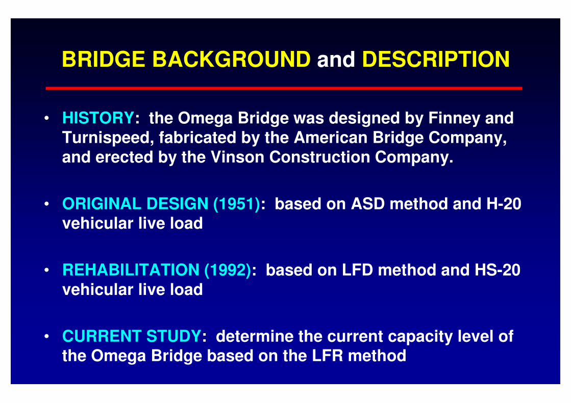
• HISTORY: the Omega Bridge was designed by Finney and Turnispeed, fabricated by the American Bridge Company, and erected by the Vinson Construction Company.
• ORIGINAL DESIGN (1951): based on ASD method and H-20 vehicular live load
• REHABILITATION (1992): based on LFD method and HS-20 vehicular live load
• CURRENT STUDY: determine the current capacity level of the Omega Bridge based on the LFR method
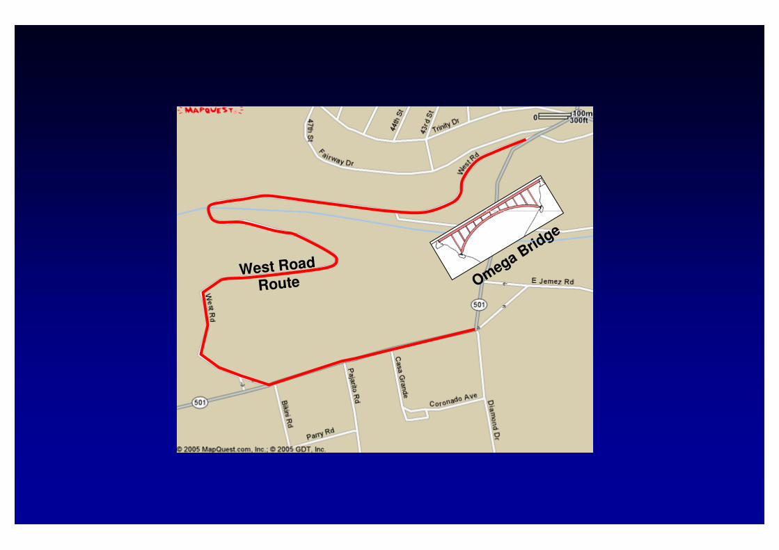
Omega Brid
ge
West Road
Route

Past Inspection and Evaluation Studies
• 1973 – HNTB (Howard Needles Tammen & Bergendoff) Corporation; conducted an in-depth bridge inspection and structural analysis of deck and superstructure
• 1983 – Holmes and Narver (with assistance from NMSU); assessed structural condition of original deck and pedestrian walkway which was later replaced
• 1988 – Merrick & Company; investigated various alternatives along with construction cost estimates for rehabilitating the Omega Bridge (done in 1992)
ExteriorStringer
West
Outrigger Beam
1.5% 1.5%
BridgeLC
7' - 412"
35' - 0"
6' - 9"3' - 6" 6' - 9"6' - 9"6' - 9" 6' - 9"7' - 412 " 3' - 6"
InteriorStringer
Floor Beam Spandrel Beam
55' - 6"
44' - 0"
Lane 111' - 0"
8' - 0"
Lane 311' - 0"
Lane 211' - 0"
Lane 411' - 0"
6' - 9"
35' - 0"
7' - 412" 6' - 9"6' - 9" 7' - 41
2"
Lane 3
9' - 1114"
51' - 312"
39' - 9"
Lane 1
9' - 1114"
7' - 6"
Lane 2
9' - 1114" 9' - 111
4"
Lane 4
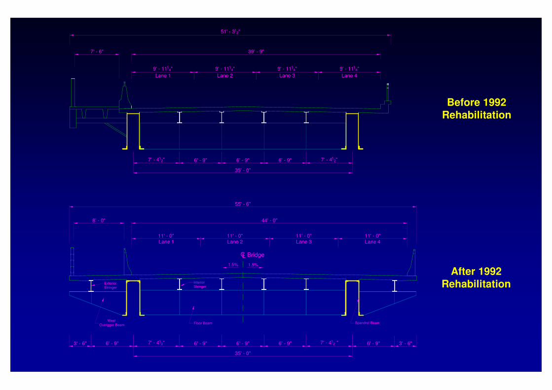
After 1992 Rehabilitation
Before 1992 Rehabilitation

Details of Bridge Rehabilitation
• Increased cross-section width (11’ traffic lanes)
• Light-weight concrete deck (28-day strength of 4.5 ksi)
• Shear studs and cover plates installed on interior stringers and spandrel beams
• Exterior stringers supported by outrigger beams added on both sides of bridge width
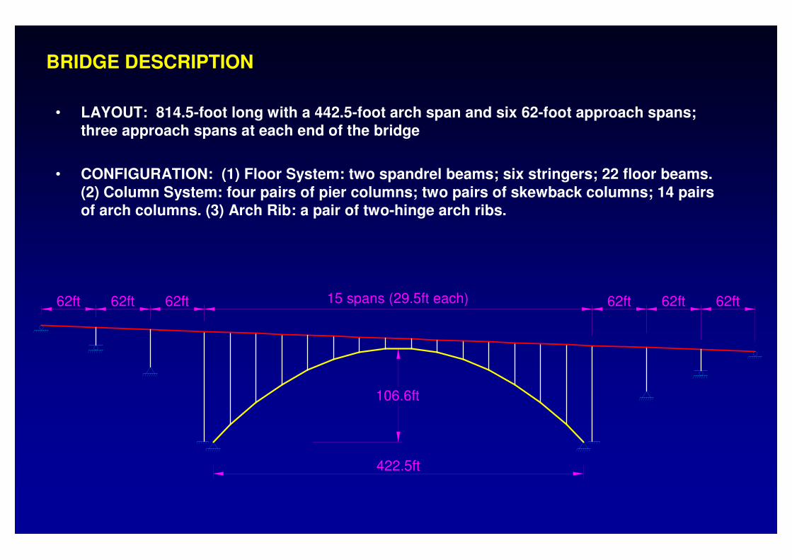
BRIDGE DESCRIPTION
• LAYOUT: 814.5-foot long with a 442.5-foot arch span and six 62-foot approach spans; three approach spans at each end of the bridge
• CONFIGURATION: (1) Floor System: two spandrel beams; six stringers; 22 floor beams. (2) Column System: four pairs of pier columns; two pairs of skewback columns; 14 pairs of arch columns. (3) Arch Rib: a pair of two-hinge arch ribs.
15 spans (29.5ft each)
422.5ft
106.6ft
62ft 62ft62ft 62ft 62ft62ft
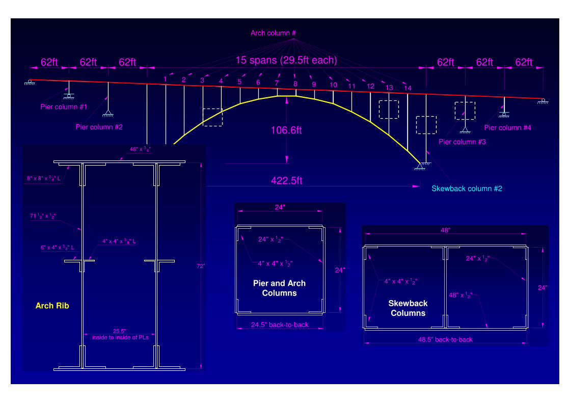
Pier column #1
Pier column #2
Pier column #3
Pier column #4
1 2 3 4 5 6 7 8 9 10 11 12 13 14
Arch column #
Skewback column #1 Skewback column #2
15 spans (29.5ft each)
422.5ft
106.6ft
62ft 62ft62ft 62ft 62ft62ft
46" x 3 4"
4" x 4" x 3 8" L6" x 4" x 3 4" L
71 12" x 12"
8" x 8" x 3 4" L
25.5"
72"
inside to inside of PLs
Arch Rib
24"
24.5" back-to-back
4" x 4" x 12"
24" x 12"
24"
Pier and Arch Columns
48"
4" x 4" x 12"
24" x 12"
48" x 12"
48.5" back-to-back
24"
Skewback Columns
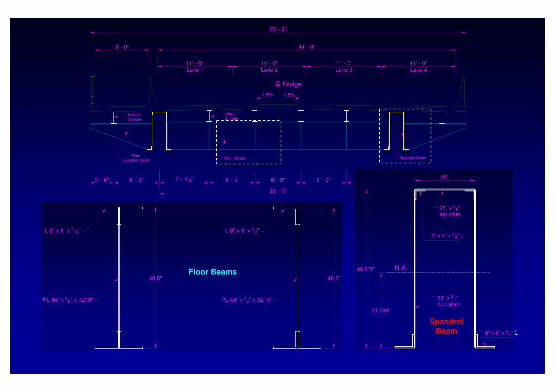
Exterior
Stringer
West
Outrigger Beam
1.5% 1.5%
BridgeLC
7' - 412"
35' - 0"
6' - 9"3' - 6" 6' - 9"6' - 9"6' - 9" 6' - 9"7' - 412 " 3' - 6"
Interior
Stringer
Floor Beam Spandrel Beam
55' - 6"
44' - 0"
Lane 111' - 0"
8' - 0"
Lane 311' - 0"
Lane 211' - 0"
Lane 411' - 0"
48.5"
L 8" x 6" x 916"
PL 48" x 3 8" x 32'-9" PL 48" x 38" x 32'-9"
L 8" x 6" x 5 8"
48.5"Floor Beams
4" x 4" x 3 8" L
8" x 6" x 3 4" L
66.875"
31.789"
25"
N.A.
25" x 3 8" top plate
66" x 3 8" web plate
L
Spandrel Beam
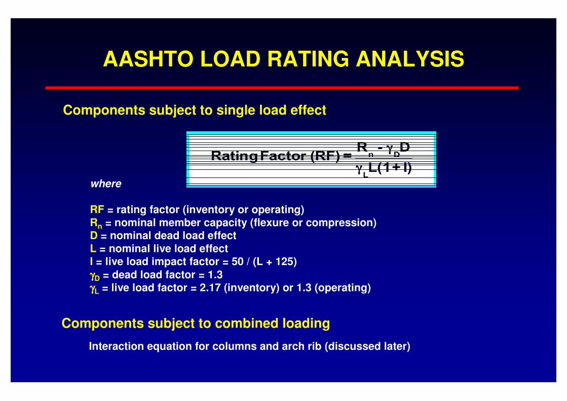
AASHTO LOAD RATING ANALYSIS
where
RF = rating factor (inventory or operating)Rn = nominal member capacity (flexure or compression)D = nominal dead load effectL = nominal live load effect I = live load impact factor = 50 / (L + 125)
γγγγD = dead load factor = 1.3γγγγL = live load factor = 2.17 (inventory) or 1.3 (operating)
Components subject to single load effect
Components subject to combined loading
Interaction equation for columns and arch rib (discussed later)
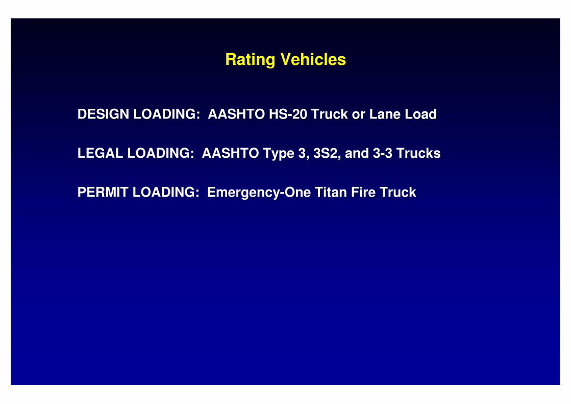
Rating Vehicles
DESIGN LOADING: AASHTO HS-20 Truck or Lane Load
LEGAL LOADING: AASHTO Type 3, 3S2, and 3-3 Trucks
PERMIT LOADING: Emergency-One Titan Fire Truck

Rating Vehicles (cont.)
38.87 k18.98 k
5 ft 12.7 ft 5 ft
18.98 k 19.89 k 19.89 k 38.87 k
7.2 ft
AXLE NO.1 2 3 4
8 k
36 k 36 k
14ft 14 to 30 ft 6ft
AXLE NO.1 2 3
32 k32 k
Fire Truck: 77.74 kips
HS-20 Truck: 72 kips
Legal Trucks: 50, 72, and 80 kips

16 k 17 k17 k
15 ft 4 ft
10 k
12 k12 k
15 ft 4 ft
12 k 14 k
16 ft
16 k
4 ft
14 k
15 ft
15.5 k 15.5 k 15.5 k 15.5 k
4 ft 22 ft 4 ft11 ft
AXLE NO.1
AXLE NO.1
AXLE NO.1
2 3
2 3 4 5
2 3 4 5 6
(a) TYPE 3: Unit Weight = 50 kips
(b) TYPE 3S2: Unit Weight = 72 kips
(c) TYPE 3-3: Unit Weight = 80 kips
6ft
25 k 25 k
6ft
36 k 36 k
6ft
40 k 40 k
LOAD RATING of FLOOR SYSTEM

NOTE: The four interior stringers are W21x62 sections of ASTM A7 steel;
The two exterior stringers are W21x62 sections of ASTM A36 steel.
Section #1: Positive moment, composite section (top and bottom cover plates)
Section #2: Negative moment, non-composite section (no cover plates)
Section #3: Positive moment, non-composite section (no cover plates)
Section #1: Positive moment, composite section (no cover plates)
Section #2: Negative moment, non-composite section (no cover plates)
Section #3: Positive moment, non-composite section (no cover plates)
Exterior Stringer
Interior Stringer
N1 N2 N3 N4 N5 N6 N7
N3 N4 N5 N6 N7N2N1
(Abutment) (Pier Col #1) (Pier Col #2) (Skewback Col #1)
(Skewback Col #1)(Pier Col #2)(Pier Col #1)(Abutment)
Description of Rating Model: Stringers
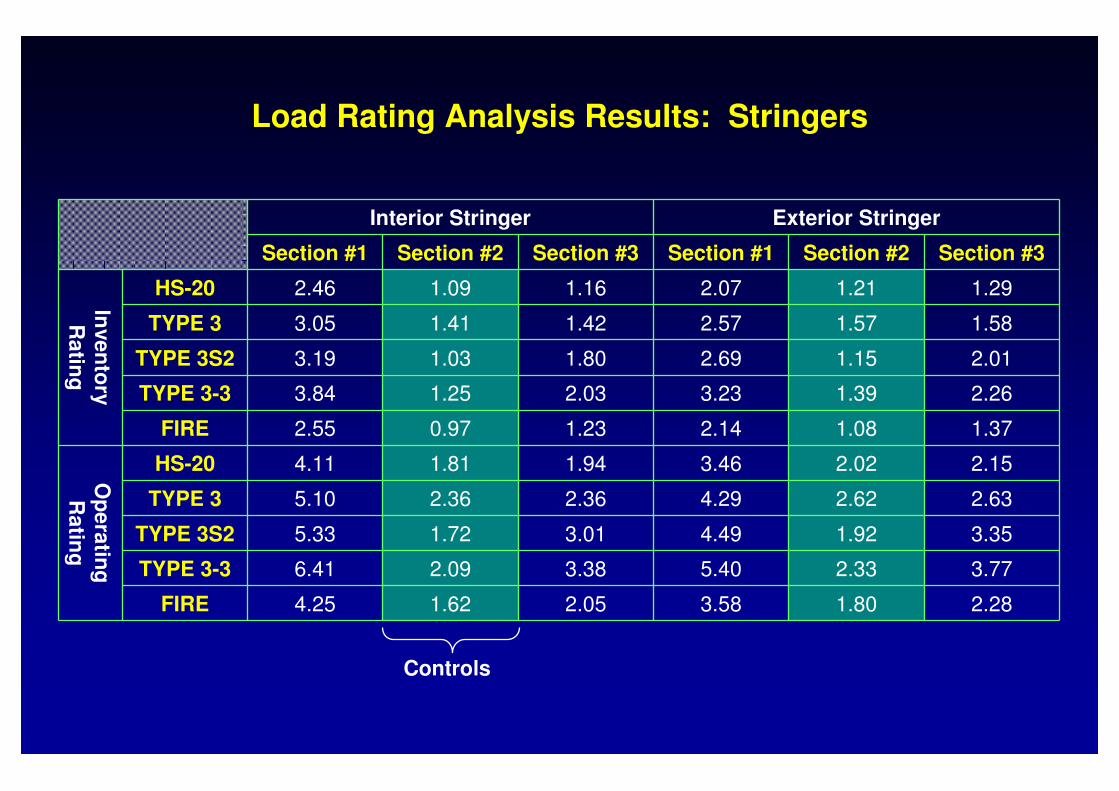
Load Rating Analysis Results: Stringers
Interior Stringer Exterior Stringer
Section #1 Section #2 Section #3 Section #1 Section #2 Section #3
Inve
nto
ry
Ra
ting
HS-20 2.46 1.09 1.16 2.07 1.21 1.29
TYPE 3 3.05 1.41 1.42 2.57 1.57 1.58
TYPE 3S2 3.19 1.03 1.80 2.69 1.15 2.01
TYPE 3-3 3.84 1.25 2.03 3.23 1.39 2.26
FIRE 2.55 0.97 1.23 2.14 1.08 1.37
Op
era
ting
R
atin
g
HS-20 4.11 1.81 1.94 3.46 2.02 2.15
TYPE 3 5.10 2.36 2.36 4.29 2.62 2.63
TYPE 3S2 5.33 1.72 3.01 4.49 1.92 3.35
TYPE 3-3 6.41 2.09 3.38 5.40 2.33 3.77
FIRE 4.25 1.62 2.05 3.58 1.80 2.28
Controls
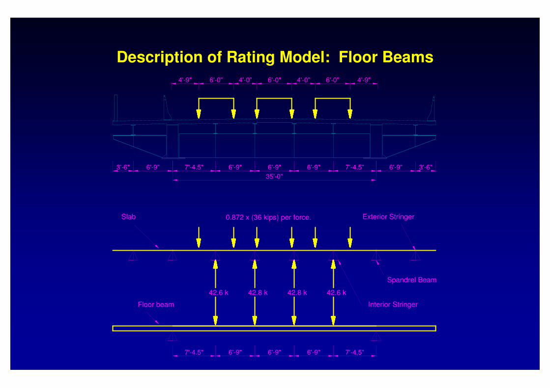
6'-9"7'-4.5"
Floor beam
42.6 k
7'-4.5"6'-9"6'-9"
42.8 k42.8 k 42.6 k
Spandrel Beam
Interior Stringer
0.872 x (36 kips) per force.
4'-0"
6'-9"
35'-0"
3'-6" 6'-9" 7'-4.5"
Slab
4'-9" 6'-0"
7'-4.5"6'-9" 6'-9" 3'-6"6'-9"
Exterior Stringer
4'-9"4'-0"6'-0" 6'-0"
Description of Rating Model: Floor Beams
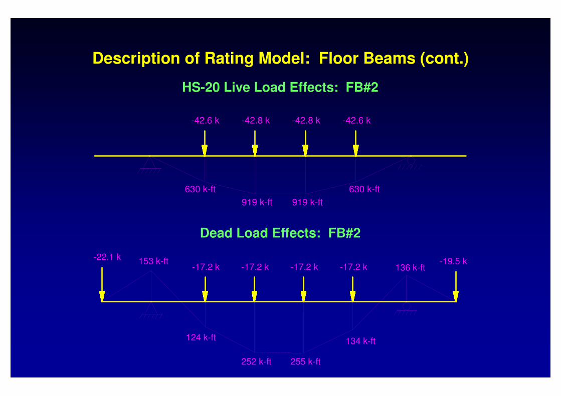
HS-20 Live Load Effects: FB#2
630 k-ft
-42.6 k
630 k-ft
919 k-ft919 k-ft
-42.6 k -42.8 k-42.8 k
252 k-ft
-17.2 k
124 k-ft
-22.1 k-17.2 k
153 k-ft
134 k-ft
255 k-ft
136 k-ft-17.2 k -17.2 k-19.5 k
Dead Load Effects: FB#2
Description of Rating Model: Floor Beams (cont.)
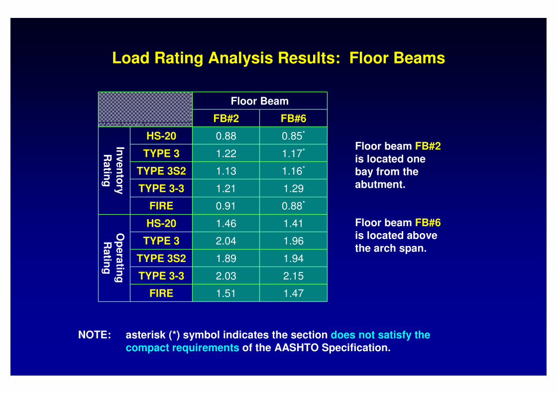
NOTE: asterisk (*) symbol indicates the section does not satisfy the compact requirements of the AASHTO Specification.
Floor beam FB#2is located one bay from the abutment.
Floor beam FB#6is located above the arch span.
Load Rating Analysis Results: Floor Beams
Floor Beam
FB#2 FB#6
Inve
nto
ry
Ra
ting
HS-20 0.88 0.85*
TYPE 3 1.22 1.17*
TYPE 3S2 1.13 1.16*
TYPE 3-3 1.21 1.29
FIRE 0.91 0.88*
Op
era
ting
R
atin
g
HS-20 1.46 1.41
TYPE 3 2.04 1.96
TYPE 3S2 1.89 1.94
TYPE 3-3 2.03 2.15
FIRE 1.51 1.47

BEAM Model
FRAME Model
Abutment Pier Col #1 Pier Col #2 Skewback Col #1 Arch Col #1 Arch Col #2 Arch Col #3
SOUTH
Pinned
Roller
SOUTH NORTH
Fixed
Roller
Pinned
Fixed
Description of Rating Model: Spandrel Beam
Section #1: Positive moment, composite section
Section #2: Negative moment, composite section
Section #3: Positive moment, non-composite section
Abutment Pier Col #1 Pier Col #2 Skewback Col #1
Section #4: Negative moment, non-composite section
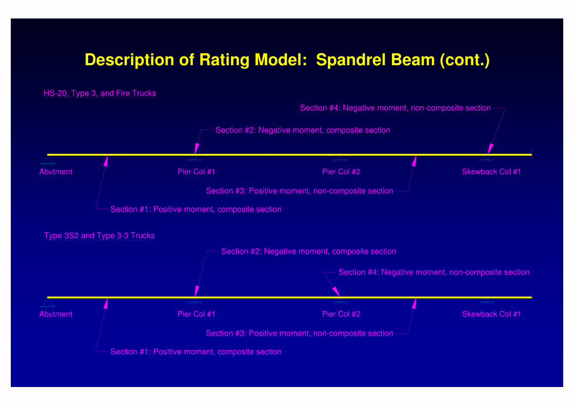
HS-20, Type 3, and Fire Trucks
Description of Rating Model: Spandrel Beam (cont.)
Section #4: Negative moment, non-composite section
Type 3S2 and Type 3-3 Trucks
Section #1: Positive moment, composite section
Abutment
Section #3: Positive moment, non-composite section
Section #2: Negative moment, composite section
Pier Col #1 Pier Col #2 Skewback Col #1
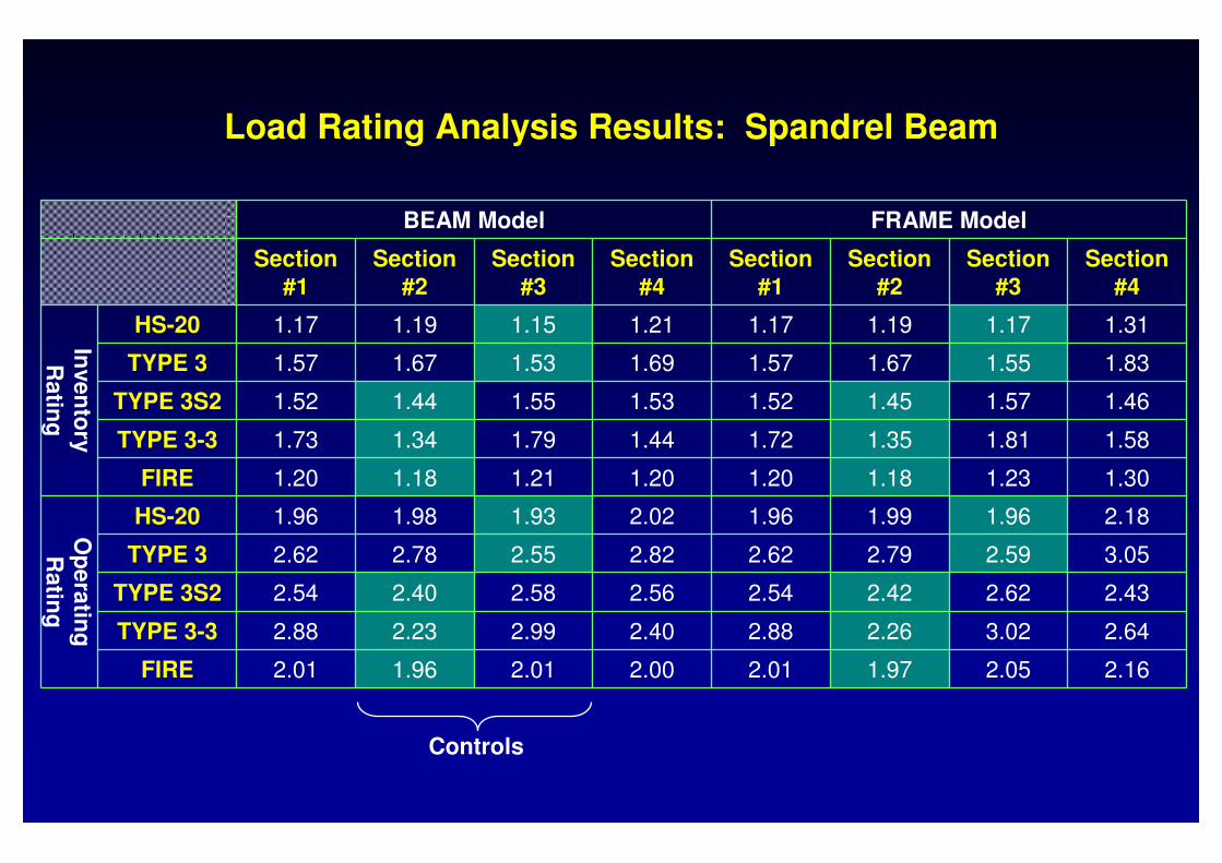
Load Rating Analysis Results: Spandrel Beam
Controls
BEAM Model FRAME Model
Section #1
Section #2
Section #3
Section #4
Section #1
Section #2
Section #3
Section #4
Inve
nto
ry
Ra
ting
HS-20 1.17 1.19 1.15 1.21 1.17 1.19 1.17 1.31
TYPE 3 1.57 1.67 1.53 1.69 1.57 1.67 1.55 1.83
TYPE 3S2 1.52 1.44 1.55 1.53 1.52 1.45 1.57 1.46
TYPE 3-3 1.73 1.34 1.79 1.44 1.72 1.35 1.81 1.58
FIRE 1.20 1.18 1.21 1.20 1.20 1.18 1.23 1.30
Op
era
ting
R
atin
g
HS-20 1.96 1.98 1.93 2.02 1.96 1.99 1.96 2.18
TYPE 3 2.62 2.78 2.55 2.82 2.62 2.79 2.59 3.05
TYPE 3S2 2.54 2.40 2.58 2.56 2.54 2.42 2.62 2.43
TYPE 3-3 2.88 2.23 2.99 2.40 2.88 2.26 3.02 2.64
FIRE 2.01 1.96 2.01 2.00 2.01 1.97 2.05 2.16
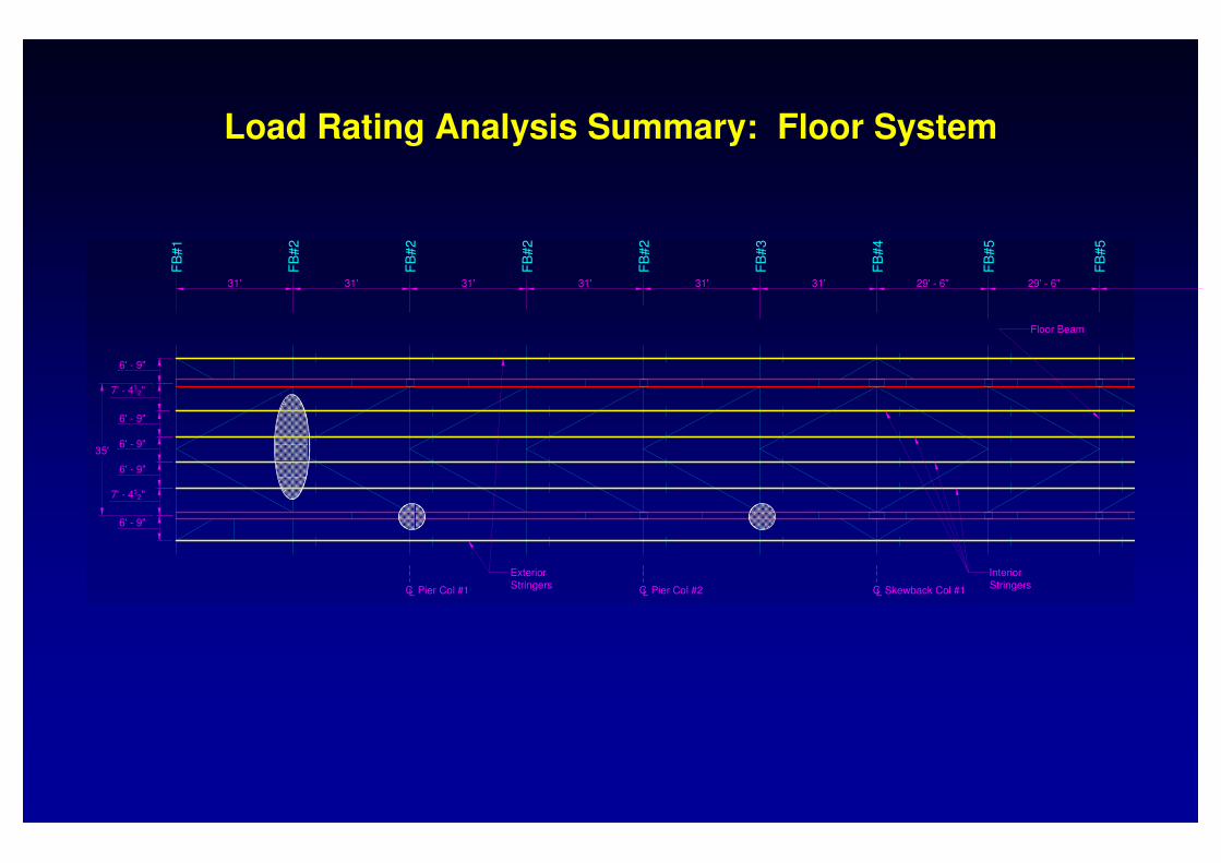
31' 31' 31' 31' 31' 31' 29' - 6" 29' - 6"
FB
#1
FB
#2
FB
#2
FB
#2
FB
#2
FB
#3
FB
#4
FB
#5
FB
#5
Interior
StringersSkewback Col #1LCPier Col #2CLPier Col #1LC
7' - 412"
6' - 9"
6' - 9"
6' - 9"
7' - 412"
6' - 9"
6' - 9"
35'
Exterior
Stringers
Floor Beam
Load Rating Analysis Summary: Floor System

31' 31' 29' - 6" 29' - 6" 29' - 6" 29' - 6" 29' - 6" 29' - 6" 29' - 6" 14' - 9"
FB
#3
FB
#4
FB
#5
FB
#5
FB
#5
FB
#6
FB
#6
FB
#6
FB
#6
Wind BracingSpandrel Beams
Outrigger BeamColumn
Interior
StringersSkewback Col #1LC
Floor Beam
Load Rating Analysis Summary: Floor System (cont.)

LOAD RATING of COLUMNS

BEAM-COLUMN Model (axial-bending interaction)
COLUMN Model (axial load only)
Description of Rating Model: Columns
15 spans (29.5ft each)
422.5ft
106.6ft
62ft 62ft62ft 62ft 62ft62ft

AASHTO Interaction Equation (rewritten for side-sway case):
where
P = maximum axial compressionAs = cross-sectional area of columnFcr = critical buckling stressMu = maximum flexural strength (equal to yield moment for all columns)Mnt = first order moment assuming no lateral end translation (i.e., non-sway case)Mlt = first order moment due to lateral end translation (i.e., sway-case)B1 = MAF for second order effect of Mnt (i.e., P-δδδδ effects)
B2 = MAF for second order effect of Mlt (i.e., P-∆∆∆∆ effects)
C = equivalent moment factorFe1, Fe2 = Euler Buckling stress for non-sway and side-sway buckling, respectively.
1
s e1
C B 1
P1
A F
= ≥−
2
s e2
1 B 1
P1
A F
= ≥∑−
∑
B1 = 1 since C ≤ 0.6
B2 = 1 since is large compared to2s eA F∑ P∑
P
0.85AsF
cr
+ B
1M
nt+ B
2M
lt
Mu
≤1
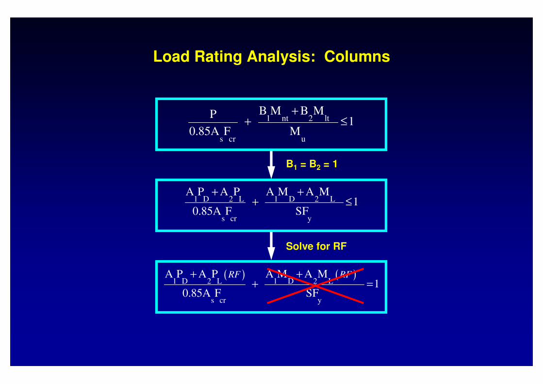
Load Rating Analysis: Columns
1 nt 2 lt
s cr u
B M B M P 1
0.85A F M
++ ≤
1 D 2 L 1 D 2 L
s cr u s cr y
A P A P A M A M 1
0.85A F M 0.85A F SF
+ ++ = + ≤
B1 = B2 = 1
( ) ( )1 D 2 L 1 D 2 L
s cr y
A P A P A M A M 1
0.85A F SF
RF RF+ ++ =
Solve for RF

ColumnHS-20 TYPE 3 TYPE 3S2 TYPE 3-3 FIRE
RFi,b-c RFi,col RFi,b-c RFi,col RFi,b-c RFi,col RFi,b-c RFi,col RFi,b-c RFi,col
Pier Col #3 1.42 3.26 2.03 4.64 1.48 3.51 1.37 3.37 1.40 3.22
Pier Col #4 N/A 3.19 N/A 4.55 N/A 3.39 N/A 3.22 N/A 3.15
Arch Col #6 0.80 4.38 1.13 6.07 0.89 6.03 0.86 6.67 0.80 4.37
Arch Col #7 0.91 4.40 1.29 6.09 0.98 6.06 0.94 6.69 0.90 4.38
Arch Col #10 0.76 4.33 1.07 6.00 0.84 5.97 0.81 6.59 0.76 4.32
Arch Col #11 0.84 4.20 1.19 5.81 0.92 5.78 0.89 6.39 0.83 4.18
Arch Col #12 0.90 3.93 1.27 5.45 0.98 5.41 0.93 5.99 0.89 3.92
Arch Col #13 1.02 3.41 1.46 4.72 1.11 4.70 1.05 5.19 1.01 3.40
Arch Col #14 1.31 2.69 1.87 3.72 1.43 3.65 1.36 4.03 1.30 2.67
Skewback Col #2 2.63 4.56 3.71 6.45 3.10 5.14 3.18 5.13 2.61 4.51
Load Rating Analysis Results: Columns
LOAD RATING of ARCH RIB

Description of Rating Model: Arch Rib
RIGID Model: “rigid” behavior of riveted connections; same as BEAM-COLUMN Model used to analyze columns
PINNED Model: “pinned” behavior of riveted connections; same as COLUMN Model used to analyze columns
15 spans (29.5ft each)
422.5ft
106.6ft
62ft 62ft62ft 62ft 62ft62ft
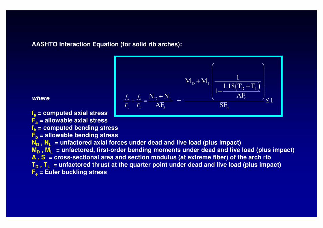
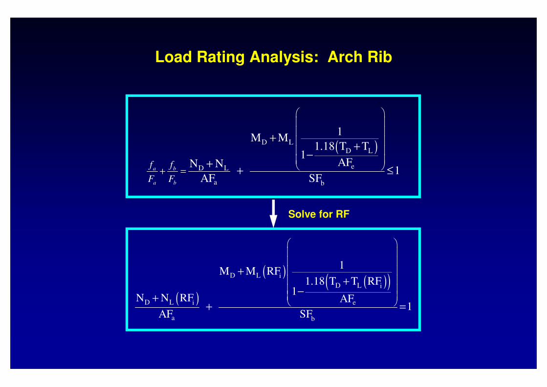
AASHTO Interaction Equation (for solid rib arches):
where
fa = computed axial stressFa = allowable axial stressfb = computed bending stressFb = allowable bending stressND , NL = unfactored axial forces under dead and live load (plus impact)MD , ML = unfactored, first-order bending moments under dead and live load (plus impact)A , S = cross-sectional area and section modulus (at extreme fiber) of the arch ribTD , TL = unfactored thrust at the quarter point under dead and live load (plus impact)Fe = Euler buckling stress
( )D L
D L
eD L
a b
1M M
1.18 T T1
AFN N 1
AF SFa b
a b
f f
F F
+ =
++
−+
+ ≤
( )D L
D L
eD L
a b
1M M
1.18 T T1
AFN N 1
AF SFa b
a b
f f
F F
+ =
++
−+
+ ≤
( )
( )( )( )D L i
D L i
D L ei
a b
1M M RF
1.18 T T RF1
N N RF AF 1
AF SF
++
−+
+ =
Solve for RF
Load Rating Analysis: Arch Rib
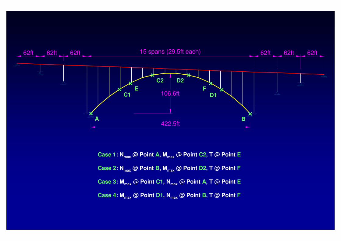
15 spans (29.5ft each)
422.5ft
106.6ft
62ft 62ft62ft 62ft 62ft62ft
A
C1E
C2 D2
FD1
B
Case 1: Nmax @ Point A, Mmax @ Point C2, T @ Point E
Case 2: Nmax @ Point B, Mmax @ Point D2, T @ Point F
Case 3: Mmax @ Point C1, Nmax @ Point A, T @ Point E
Case 4: Mmax @ Point D1, Nmax @ Point B, T @ Point F

Rating Vehicle
CaseRIGID Model PINNED Model
IRi RFi RFo IRi RFi RFo
HS201 0.56 2.53 4.23 0.57 2.41 4.02
3 0.63 2.14 3.57 0.69 1.77 2.96
TYPE 31 0.48 3.58 5.98 0.48 3.47 5.79
3 0.53 3.05 5.10 0.58 2.53 4.23
TYPE 3S21 0.53 2.81 4.69 0.56 2.35 3.92
3 0.60 2.32 3.87 0.66 1.80 3.01
TYPE 3-31 0.54 2.68 4.48 0.58 2.54 4.24
3 0.62 2.21 3.68 0.69 1.91 3.19
FIRE1 0.56 2.49 4.17 0.57 2.39 3.99
3 0.63 2.12 3.54 0.70 1.76 2.93
Controls
Load Rating Analysis Results: Arch Rib

15 spans (29.5ft each)
422.5ft
106.6ft
62ft 62ft62ft 62ft 62ft62ft
Load Rating Analysis Summary: Columns and Arch Rib

Bridge Component
Design Load
Legal Load
Permit Load
RFi RFo RFi RFo RFi RFo
Stringer 1.09 1.81 1.03 1.72 0.97 1.62
Floor beam 0.85 1.14 1.13 1.89 0.88 1.47
Spandrel beam 1.15 1.93 1.34 2.23 1.18 1.96
Pier Column 1.18 1.97 1.13 1.89 1.16 1.94
Arch Column 0.76 1.27 0.81 1.36 0.76 1.26
Skewback Column 2.63 4.39 3.10 5.18 2.61 4.35
Arch Rib 1.77 2.96 1.80 3.01 1.75 2.93
BEAM or FRAME Model
PINNED Model
BEAM-COLUMN Model
FINAL LOAD RATING
1. The rating factors of the columns are inversely proportional to the stiffness of the riveted connections. In actuality, the connection stiffness may be somewhere between fully rigid and pinned behavior and thus, the rating factors of the columns will fall somewhere between the rating values of BEAM-COLUMN and COLUMN models.
2. Another important observation is that, while the rigidity of the end-column connection helps to increase the capacity of the spandrel beam and the arch rib, it significantly reduces the capacity of the columns.
3. In the scope of this study, the rating factor of the arch column and the floor beam controlled the final rating of the entire bridge. However, it is anticipated that the rating factors of the columns may no longer control if the actual connection stiffness is taken into account (recommended for future work to improve column rating factors).
Discussion

CONCLUSIONS and RECOMMENDATIONS
• Column rating factors are inversely proportional to the stiffness of the riveted connections while arch rib rating factors aredirectly proportional; spandrel beam was not affected by connection stiffness at critical sections.
• In general, the Omega Bridge is structurally sound with some concerns for the floor beams and arch columns.
• Since the smallest rating factors for legal loads are RFi = 0.81and RFo = 1.36, posting of the bridge is not required but additional inspection and traffic monitoring may be warranted.
• Further studies (i.e., field testing along with 3D finite element analysis) are recommended to improve the rating factors.

THANK YOU