clutch catalog pdf set-up - KJ · PDF file4 CTS Clutch – Thru Shaft Thru-shaft mounted...
52
1 Contents Product Line Summary . . . . . . . . . . . . . . . . . . . . . . . . . . . 4-6 Selection . . . . . . . . . . . . . . . . . . . . . . . . . . . . . . . . . . . . . . 7-8 Super-Mod® Clutches and Brakes . . . . . . . . . . . . . . . . . . 9-20 Selection . . . . . . . . . . . . . . . . . . . . . . . . . . . . . . . . . . . 11-12 Clutch-Brakes: 1020, 1020WD (Washdown) and 2030 Modules . . . . . . . . . . . . . . . . . . . . . . . . . . . . 13 Clutches: 1040, 1040WD (Washdown) and 3040 Modules . . . . . . . . . . . . . . . . . . . . . . . . . . . . 14 Brakes: 20, 20WD (Washdown) and 20MB Modules . . . . . . . . . . . . . . . . . . . . . . . . . . . 15 Conversion Kits . . . . . . . . . . . . . . . . . . . . . . . . . . . . . . 16 Outline Drawing . . . . . . . . . . . . . . . . . . . . . . . . . . . . . . 17-18 Competitive Interchanges . . . . . . . . . . . . . . . . . . . . . . 19-20 Traditional Clutches . . . . . . . . . . . . . . . . . . . . . . . . . . . . . 21-27 CCC Clutch - Clutch Coupling . . . . . . . . . . . . . . . . . . 22 CRP Clutch - Roto Sheave® Units . . . . . . . . . . . . . . . 23 CRS Clutch - Roto Sprocket® Units . . . . . . . . . . . . . . . 24-26 CTS Clutch - Thru Shaft . . . . . . . . . . . . . . . . . . . . . . . 27 Heavy Duty Clutches and Brakes . . . . . . . . . . . . . . . . . . 28-45 Selection . . . . . . . . . . . . . . . . . . . . . . . . . . . . . . . . . . . 28-29 Outline of Heavy Duty Products . . . . . . . . . . . . . . . . . 30-31 Electrically-Engaged Clutches Style E . . . . . . . . . . . . . . . . . . . . . . . . . . . . . . . . . . . . . 32-33 Style E, Class S (Straight Bores) . . . . . . . . . . . . . . . . . 34-35 Style E, Class S (Tapered Bores) . . . . . . . . . . . . . . . . 36-37 Style E, Class M . . . . . . . . . . . . . . . . . . . . . . . . . . . . . . 38-39 Spring-Engaged Clutches Style SCE, Class S3 (Straight Bores) . . . . . . . . . . . . . 40-41 Style SCE, Class S3 (Tapered Bores) . . . . . . . . . . . . . 42-43 Spring-Engaged Brakes Style SCEB, Class S3 . . . . . . . . . . . . . . . . . . . . . . . . . 44-45 Rectifier Controls . . . . . . . . . . . . . . . . . . . . . . . . . . . . . 46-49 Model PR-01 . . . . . . . . . . . . . . . . . . . . . . . . . . . . . . . . 47 Model PR-33 . . . . . . . . . . . . . . . . . . . . . . . . . . . . . . . . 47 Series 12000 . . . . . . . . . . . . . . . . . . . . . . . . . . . . . . . . 48 Forcing Circuits . . . . . . . . . . . . . . . . . . . . . . . . . . . . . . 49 Application Engineering Data . . . . . . . . . . . . . . . . . . . 50-52 Sales Offices . . . . . . . . . . . . . . . . . . . . . . . . . . . . Back Cover 500 01/2011 P/N 8-178-000-13 REV G Copyright © 2011 Rexnord Industries, LLC, Stearns Division www.stearns.rexnord.com To view the complete catalog online, go to www.stearns.rexnord.com
Transcript of clutch catalog pdf set-up - KJ · PDF file4 CTS Clutch – Thru Shaft Thru-shaft mounted...

1
ContentsProduct Line Summary . . . . . . . . . . . . . . . . . . . . . . . . . . . 4-6
Selection . . . . . . . . . . . . . . . . . . . . . . . . . . . . . . . . . . . . . . 7-8
Super-Mod® Clutches and Brakes . . . . . . . . . . . . . . . . . . 9-20
Selection . . . . . . . . . . . . . . . . . . . . . . . . . . . . . . . . . . . 11-12
Clutch-Brakes: 1020, 1020WD (Washdown)and 2030 Modules . . . . . . . . . . . . . . . . . . . . . . . . . . . . 13
Clutches: 1040, 1040WD (Washdown)and 3040 Modules . . . . . . . . . . . . . . . . . . . . . . . . . . . . 14
Brakes: 20, 20WD (Washdown)and 20MB Modules . . . . . . . . . . . . . . . . . . . . . . . . . . . 15
Conversion Kits . . . . . . . . . . . . . . . . . . . . . . . . . . . . . . 16
Outline Drawing . . . . . . . . . . . . . . . . . . . . . . . . . . . . . . 17-18
Competitive Interchanges . . . . . . . . . . . . . . . . . . . . . . 19-20
Traditional Clutches . . . . . . . . . . . . . . . . . . . . . . . . . . . . . 21-27
CCC Clutch - Clutch Coupling . . . . . . . . . . . . . . . . . . 22
CRP Clutch - Roto Sheave® Units . . . . . . . . . . . . . . . 23
CRS Clutch - Roto Sprocket® Units . . . . . . . . . . . . . . . 24-26
CTS Clutch - Thru Shaft . . . . . . . . . . . . . . . . . . . . . . . 27
Heavy Duty Clutches and Brakes . . . . . . . . . . . . . . . . . . 28-45
Selection . . . . . . . . . . . . . . . . . . . . . . . . . . . . . . . . . . . 28-29
Outline of Heavy Duty Products . . . . . . . . . . . . . . . . . 30-31
Electrically-Engaged Clutches
Style E . . . . . . . . . . . . . . . . . . . . . . . . . . . . . . . . . . . . . 32-33
Style E, Class S (Straight Bores) . . . . . . . . . . . . . . . . . 34-35
Style E, Class S (Tapered Bores) . . . . . . . . . . . . . . . . 36-37
Style E, Class M . . . . . . . . . . . . . . . . . . . . . . . . . . . . . . 38-39
Spring-Engaged Clutches
Style SCE, Class S3 (Straight Bores) . . . . . . . . . . . . . 40-41
Style SCE, Class S3 (Tapered Bores) . . . . . . . . . . . . . 42-43
Spring-Engaged Brakes
Style SCEB, Class S3 . . . . . . . . . . . . . . . . . . . . . . . . . 44-45
Rectifier Controls . . . . . . . . . . . . . . . . . . . . . . . . . . . . . 46-49
Model PR-01 . . . . . . . . . . . . . . . . . . . . . . . . . . . . . . . . 47
Model PR-33 . . . . . . . . . . . . . . . . . . . . . . . . . . . . . . . . 47
Series 12000 . . . . . . . . . . . . . . . . . . . . . . . . . . . . . . . . 48
Forcing Circuits . . . . . . . . . . . . . . . . . . . . . . . . . . . . . . 49
Application Engineering Data . . . . . . . . . . . . . . . . . . . 50-52
Sales Offices . . . . . . . . . . . . . . . . . . . . . . . . . . . . Back Cover
500 01/2011 P/N 8-178-000-13 REV G Copyright© 2011 Rexnord Industries, LLC, Stearns Division www.stearns.rexnord.com
To view the complete catalog online, go to www.stearns.rexnord.com

2
AdditionalProducts/CatalogsSolenoid Actuated Brakes(SAB’s)
Stearns offers the mostcomprehensive line of solenoidactuated brakes (SAB’s) on themarket today. Stearns spring-setmotor brakes can be mounteddirectly to the electric motor or footmounted. The compact designdelivers high torque in a small sizewith fast, positive response and noresidual drag when released. Ourbrakes can be mounted directlyonto NEMA C-face motors withoutspecial alignment procedures.Many motor manufactures offer abrake kit which will convert a stockfan-cooled motor into a brakemotor.Stearns Solenoid Actuated brakesfeature unitized construction whichmakes servicing friction discs easyusing only a screwdriver andwrench. The Stearns SAB ensuresautomatic stopping and holding anytime power to the brake isinterrupted. And, as with ALLStearns products, the frictionmaterial in non-asbestos. Ask forBrake Catalog p/n 8-178-000-12.Armature Actuated Brakes(AAB’s)
Armature Actuated Brakes (AAB’s)are spring-set, direct acting frictionbrakes which develop holding anddynamic torque in the absence ofelectrical power. Stearns now offersa wide range of AAB’s whichprovide high torque in compact,easy-to-install units.
Series 310 is a high performanceServo brake for holding-onlyapplications. Series 321 providesdynamic stopping or holding torquein a compact economical package.Series 333 features torque andwear adjustment capabilities and isa direct interchange with Europeanbrake manufacturers. Series 350
pressure plate mount and Series360 magnet body mount, both forNEMA C-face or IEC mounting, areideal for portal crane applications.Each series has its own separatebrochure, or you can ask for BrakeCatalog p/n 8-178-000-12.
Sinpac® Switches
For over 75 years, single-phasemotors have utilized a mechanicalcentrifugal switch to switch the startcircuit. Inherent characteristics of amechanical device have madethese switches prone to variousproblems, including tolerances,tolerance buildups, mechanicalfatigue, vibration and a host ofothers that can lead to switchfailures and/or performanceinconsistency.
Our challenge was to design areliable solid-state switch to replacethe mechanical switch and actuatormechanism that would duplicatethe function of connecting anddisconnecting the start circuit atparticular speeds with the additionalbenefits of a solid-state device.After considerable research, wedecided a successful electronicmotor starting switch could becreated by sensing the voltagespresent in the main and startwindings. SINPAC Switches arepotted and completely sealed,making them impervious to dust,dirt and moisture. The uniquespeed sensing circuit provides auniversal design which allows a fewswitches to work on most standardmotor designs regardless ofmanufacturer.
Acceptance by MotorManufacturesUS and foreign motormanufacturers have tested andretested the SINPAC Switch forreliability and quality. Today, manyof these manufacturers have beguninstalling SINPAC Switches on their
standard motor lines with morecompanies ready to make thechangeover.
UL RecognitionMany SINPAC Switches havealready been recognized under theComponent Program ofUnderwriters Laboratories, Inc. (E-71115). In addition, all switcheshave internal surge protectionwhich is tested according to IEEE C62.41 - 1991 Category A3. CSACertification LR-6254.Request SINPAC CatalogP/N 8-178-000-16.
All of the product catalogs are available atwww.stearns.rexnord.com
BACK TO TABLE OF CONTENTS
3
Stearns® Electromagnetic Brakes, Clutches and Electronic Components
Built to Put You in Control
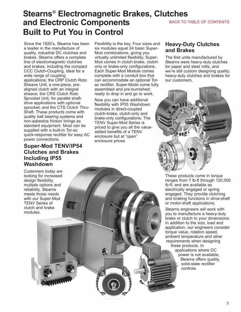
Since the 1920’s, Stearns has beena leader in the manufacture ofquality, industrial DC clutches andbrakes. Stearns offers a completeline of electromagnetic clutchesand brakes, including the compactCCC Clutch-Coupling, ideal for awide range of couplingapplications; the CRP Clutch RotoSheave Unit, a one-piece, pre-aligned clutch with an integralsheave; the CRS Clutch RotoSprocket Unit, for parallel shaft-drive applications with optionalsprocket; and the CTS Clutch Thru-Shaft. These products come withquality ball bearing systems andnon-asbestos friction linings asstandard equipment. Most can besupplied with a built-in Tor-acquick-response rectifier for easy ACpower connections.
Super-Mod TENV/IP54Clutches and BrakesIncluding IP55Washdown
Customers today arelooking for increaseddesign flexibility,multiple options andreliability. Stearnsmeets those needswith our Super-ModTENV Series ofclutch and brakemodules.
Flexibility is the key. Four sizes andsix modules equal 24 basic Super-Mod combinations, giving youvirtually unlimited flexibility. Super-Mod comes in clutch-brake, clutch-only or brake-only configurations.Each Super-Mod Module comescomplete with a conduit box thatcan accommodate an optional Tor-ac rectifier. Super-Mods come fullyassembled and pre-burnished;ready to drop in and go to work.
Now you can have additionalflexibility with IP55 Washdownmodules in direct-coupledclutch-brake, clutch-only andbrake-only configurations. TheTENV Super-Mod Series ispriced to give you all the value-added benefits of a TENVenclosure but at “open”enclosure prices.
Heavy-Duty Clutchesand Brakes
The first units manufactured byStearns were heavy-duty clutchesfor paper and steel mills, andwe’re still custom designing quality,heavy-duty clutches and brakes forour customers.
These products come in torqueranges from 7 lb-ft through 120,000lb-ft, and are available aselectrically engaged or springengaged. They provide clutchingand braking functions in drive-shaftor motor-shaft applications.
Stearns engineers will work withyou to manufacture a heavy-dutybrake or clutch to your dimensions.In addition to the size, load andapplication, our engineers considertorque value, rotation speed,ambient temperature and otherrequirements when designing
these products. In applications where DC
power is not available,Stearns offers quality, solid-state rectifiercontrols.
BACK TO TABLE OF CONTENTS

4
CTS Clutch – Thru ShaftThru-shaft mounted unit with bearing supportedstationary field. Provides clutching function fortwo parallel shafts when sheave or sprocket isinstalled.
CRP Clutch –Roto Sheave Unit
One-piece shaft mounted unit with bearingsupported integral sheave and bearing supportedstationary field. Provides clutching function for twoparallel shafts with V-belt connection.
CRS Clutch –Roto Sprocket Unit
One-piece shaft mounted unit with bearingsupported integral sprocket adapter and bearingsupported stationary field. Provides clutchingfunction for two parallel shafts with chain connection.Sprocket, separate optional item.
Product Line Summary
SM Super-Mod TENV C-FaceBrake Module, with OutputShaft
The 20 Module mounts direct to a C-face motorand can then mount to a C-face gear reducer. Itcan also be direct coupled or used to connect drivenequipment by belt or chain. It is a power-on brake.
SM Super-Mod TENV C-FaceBrake Module
The 20MB Module is a power-on brake. It isdesigned to be mounted on the accessory end of adouble shafted C-face motor.
Style SCEB, Class S3Style SCEB, Class S3 Spring-Set Brake is end shaftmounted with base. Released when voltage isapplied.
Bra
kes
• 16-145 lb-ft static torque.
• 48Y/56C-256C/215TCNEMA C-face frame sizes.
• Washdown (IP55)availability for 56C-145TCNEMA frame sizes.
• See page 15 for productselection.
• See page 20 forcompetitive interchanges.
• 16-145 lb-ft static torque.
• 48Y/56C-256C/215TCNEMA C-face framesizes.
• See page 15 for productselection.
• See page 20 forcompetitive interchanges.
• 450-12,000 lb-ft statictorque.
• See pages 44 and 45for product selection.
• 60-275 lb-in statictorque.
• See page 27 forproduct selection.
• 100-1740 lb-in statictorque.
• See page 23 for productselection.
• 100-1740 lb-in statictorque.
• See page 24 forproduct selection.
Clu
tch
es
BACK TO TABLE OF CONTENTS

5
Clu
tch
es (
co
nti
nu
ed
)C
lutc
h-C
ou
plin
gs
Style E, Electrically Set ClutchShaft mounted. Available as a CLUTCH-COUPLINGor clutch. Primary field-coil design. Engaged whenvoltage is applied.
Style E, Class S Electrically SetClutch
Shaft mounted clutch-coupling with lift out feature.Primary field-coil design. Engaged when voltage isapplied.
Style E, Class M Electrically SetClutch
Shaft mounted Form 6 standard clutch-coupling withlift out capability. Primary field-coil design. Engagedwhen voltage is applied.
Style SCE, Class S3 Spring-SetClutch
Shaft mounted clutch-coupling with lift out feature.Primary field-coil design. Released when voltage isapplied.
Clu
tch
-Co
up
lin
gs (
co
nti
nu
ed
)
• 16-145 lb-ft static torque.• 48Y/56C-256C/215TC NEMA
C-face frame sizes.• Washdown (IP55) availability for
56C-145TC NEMA frame sizes.• See page 14 for product
selection.• See page 19 for competitive
interchanges.
• 16-145 lb-ft static torque.• See page 14 for product
selection.• See page 20 for
competitive interchanges.
• 7-9000 lb-ft statictorque.
• See page 32-33 forproduct selection.
• 60-1740 lb-in statictorque.
• See page 22 for productselection.
• 7-9000 lb-ft static torque.
• See pages 32-33 forproduct selection.
• 400-9000 lb-ft static torque.
• See pages 34-37 forproduct selection.
• 7-9000 lb-ft static torque.
• See pages 38-39 for productselection.
• 450-12,000 lb-ft statictorque.
• See pages 40-43 forproduct selection.
SM Super-Mod TENV C-Face Clutch Module
The 1040 Module can be mounted directly to aC-face motor with the output shaft mounted into aC-face gear reducer or coupled or connected to thedriven equipment by belt or chain.
SM Super-Mod TENV BaseMounted Clutch, Double Shafts
The 3040MB module is a foot or base mountedclutch only unit. It can be direct coupled in a drivesystem or connected through belt and/or chainequipment.
Style E, Electrically Set Clutch
Shaft mounted. Available as a clutch-coupling orCLUTCH. Primary field-coil design. Engaged whenvoltage is applied.
CCC Clutch Coupling
Shaft mounted unit with bearing supportedstationary field. Provides clutching action for two in-line shafts.
BACK TO TABLE OF CONTENTS

Heavy Duty Rectifier(s) Series12000
The heavy duty rectifier packages are single-phaseand are for use with Stearns heavy duty (mill)clutches. They incorporate a solid-state siliconbridge circuit for high efficiency.
Available with outputs of 115 or 230 Vdc and powerratings up to 1150 watts.
A transformer provides isolation and a dual AC inputcapability. Each rectifier is enclosed in a NEMA 1steel cabinet and includes a separately housedstarter/contactor with overload heaters.
Heavy Duty Forcing Circuit -Rectifiers
A combination overexcitation and rectifier for usewith Stearns SCE and SCEB, spring-set, electricallyreleased products.
Provides the momentary forcing voltage necessaryto release then drops the voltage to a holding level.The output of each unit is a forcing voltage of 230Vdc, which after a delay, drops to a holding voltageof 70 Vdc. The circuitry provides a surgesuppression network to protect the coil andminimizes the contactor arcing. The complete circuitis enclosed in a steel NEMA 12 cabinet.
6
SM Super-Mod TENV C-FaceClutch-Brake Module
The 1020 Module mounts directly to a C-face motorand can then mount to a C-face gear reducer. It canalso be direct coupled or used to connect drivenequipment by belt or chain.
SM Super-Mod TENV BaseMounted Clutch-Brake, DoubleShafted
Base mounted. Available as a clutch-coupling orclutch. Primary field-coil design. Engaged whenvoltage is applied.
Module PR-01Controls one clutch and brake, or two clutches ortwo brakes.
Internally fused for overload protection.
Module PR-33Controls one clutch and brake, or two clutches ortwo brakes.
Internally fused for overload protection.
Clu
tch
-Bra
kes
Recti
fiers
Recti
fiers
(co
nti
nu
ed
)
• 16-145 lb-ft static torque.• 48Y/56C-256C/215TC NEMA
C-face frame sizes.• Washdown (IP55) availability
for 56-145TC NEMA framesizes.
• See page 13 for productselection.
• See page 19 for competitiveinterchanges.
• 16-145 lb-ft static torque.• See page 13 for product
selection.• See page 19 for
competitive interchanges.
1.0amp
Rating
47100 Vdc115 Vac,50/60 Hz
PageOutputInput
.5amps
Rating
47
15-100Vdc onecircuit,
100 Vdcfor other
115 Vac,50/60
Hz
PageOutputInput
Available Voltages(Vac)
Page
115/230and 230/460
48
AvailableVoltages (Vac)
Page
115, 208, 230460 and 575
49
BACK TO TABLE OF CONTENTS
7
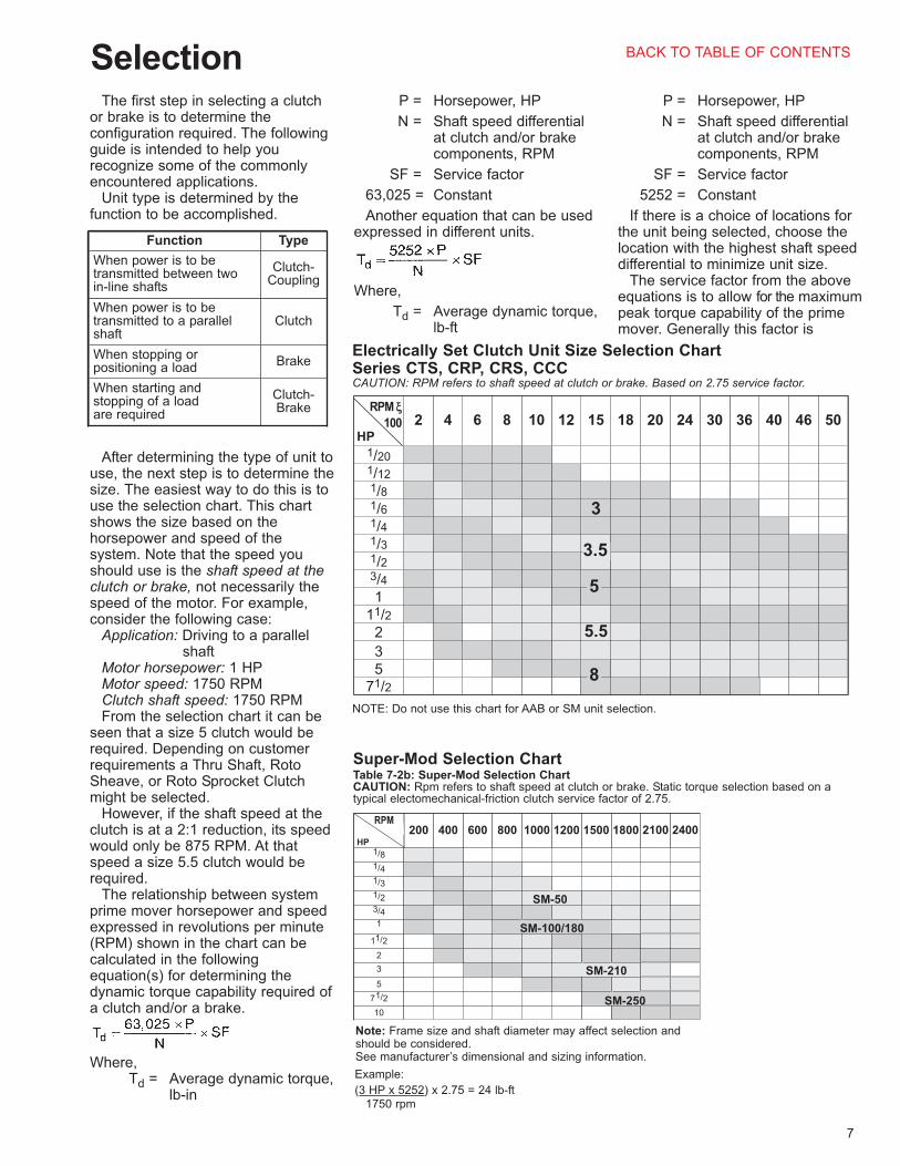
SelectionThe first step in selecting a clutch
or brake is to determine theconfiguration required. The followingguide is intended to help yourecognize some of the commonlyencountered applications.
Unit type is determined by thefunction to be accomplished.
After determining the type of unit touse, the next step is to determine thesize. The easiest way to do this is touse the selection chart. This chartshows the size based on thehorsepower and speed of thesystem. Note that the speed youshould use is the shaft speed at theclutch or brake, not necessarily thespeed of the motor. For example,consider the following case:
Application: Driving to a parallel shaft
Motor horsepower: 1 HPMotor speed: 1750 RPMClutch shaft speed: 1750 RPMFrom the selection chart it can be
seen that a size 5 clutch would berequired. Depending on customerrequirements a Thru Shaft, RotoSheave, or Roto Sprocket Clutchmight be selected.
However, if the shaft speed at theclutch is at a 2:1 reduction, its speedwould only be 875 RPM. At thatspeed a size 5.5 clutch would berequired.
The relationship between systemprime mover horsepower and speedexpressed in revolutions per minute(RPM) shown in the chart can becalculated in the followingequation(s) for determining thedynamic torque capability required ofa clutch and/or a brake.
Where,Td = Average dynamic torque,
lb-in
P = Horsepower, HP
N = Shaft speed differential at clutch and/or brake components, RPM
SF = Service factor
63,025 = Constant
Another equation that can be usedexpressed in different units.
Where,
Td = Average dynamic torque, lb-ft
P = Horsepower, HP
N = Shaft speed differential at clutch and/or brake components, RPM
SF = Service factor
5252 = Constant
If there is a choice of locations forthe unit being selected, choose thelocation with the highest shaft speeddifferential to minimize unit size.
The service factor from the aboveequations is to allow for the maximumpeak torque capability of the primemover. Generally this factor is
Clutch-Brake
When starting andstopping of a load are required
BrakeWhen stopping orpositioning a load
ClutchWhen power is to betransmitted to a parallelshaft
Clutch-Coupling
When power is to betransmitted between twoin-line shafts
TypeFunction
Electrically Set Clutch Unit Size Selection ChartSeries CTS, CRP, CRS, CCCCAUTION: RPM refers to shaft speed at clutch or brake. Based on 2.75 service factor.
71/253
5.5211/2
1
3/4
1/2
1/3
1/431/6
1/8
1/12
1/20
50464036302420181512108642RPM ξξ
100HP
8
5
3.5
NOTE: Do not use this chart for AAB or SM unit selection.
10
71/2
5
3
2
11/2
1
3/4
1/2
1/3
1/4
1/8
24001800 2100150012001000800600400200RPM x
100HP
Note: Frame size and shaft diameter may affect selection andshould be considered. See manufacturer’s dimensional and sizing information.
Super-Mod Selection ChartTable 7-2b: Super-Mod Selection ChartCAUTION: Rpm refers to shaft speed at clutch or brake. Static torque selection based on a typical electomechanical-friction clutch service factor of 2.75.
Example:
(3 HP x 5252) x 2.75 = 24 lb-ft1750 rpm
SM-50
SM-210
SM-250
SM-100/180
BACK TO TABLE OF CONTENTS

8
derived as a percentage of the fullload running torque of the primemover and expressed as given in the following table.
The dynamic torque calculatedfrom the above equation(s) can becompared to the ratings given for thevarious sizes in this catalog for theunit size selection, in the PerformanceData Tables.
Thermal CapacityAn additional factor in clutch and/or
brake selection and usage is the heatdissipation capability of the unit.When a clutch or brake is engaged toaccomplish a speed change, there issome slippage between the frictionsurfaces resulting in heat energybeing generated due to friction. Theamount of heat energy generated is afunction of the size of the load(inertia) and the frequency at which itis started and/or stopped and RPM.In order to insure that the thermalcapacity of the clutch and/or brake isnot exceeded, the followingcalculations should be made.
Where:
E = Energy (heat) which needsto be dissipated in footpounds per minute (ft-lb/min)for the application requirement (Thermal Capacity Requirement).
WR2 = Total reflected inertia at clutch-brake shaft location. This should include clutch-brake inertia (lb-ft2).
N = Speed differential in revolutions per minute (RPM)at the clutch-brake shaft.
F = Number of cycles per minute (cycle rate).
The thermal capacity requirementscalculated in this manner should thenbe compared to the thermal capacityratings as listed in the PerformanceData Tables for the size and type of
unit being selected. The requirementshould never exceed the rating oroverheating and possible prematurefailure may occur.
Note that sufficient air flow shouldbe allowed around the clutch and/orbrake to provide cooling. Shouldadditional enclosures or machinehousings be required, permit acooling air flow to move past the unit,sufficient to avoid clutch and/or brakeoverheating.
Special ApplicationConsiderations
Lubricants: Dry friction clutches andbrakes should not be used where thefriction surfaces will be subjected tooil, cutting fluid or other lubricantsand contaminates as these willreduce the torque output.
Low speed: Application of clutchesand brakes at speeds of 300 RPM orless may not permit sufficientburnishing or run-in to occur, theresult being reduced and erratictorque output. For these applicationsit is suggested that a unit be usedwhich has a static torque rating of atleast two times the calculated torquerequirement.
High speed: Application of clutchesand brakes at speeds higher thanrecommended could reduce bearinglife and cause fatigue failures andgalling.
High cycle rates: Applicationswhere high cycle rates are requiredcould result in heat generated whichis in excess of the unit’s capability todissipate. The thermal capacityrequirement equation should be usedto size the clutch and/or brake forthis type of application. High cyclerates may also require special highspeed controls.
Vertical applications: (CCC, CRP,CRS and CTS only) With thearmature situated above the frictionsurface, spring release is necessaryto avoid excessive heat, drag andnoise.
With the armature situated belowthe friction surface, spring release isnot desirable. Gravity should besufficient to move the armature away,thereby providing the open runningair gap.
For those situations with additionalconsiderations, you should contactthe factory; our application engineers
will be more than happy to assist youwith your application questions.Super-Mod can be used in verticalapplications without any modification.
5-10Gasoline or diesel enginedrive through a clutch
2-4Electric motor drivethrough a clutch
1-2Brake only
SFApplication
BACK TO TABLE OF CONTENTS

9
TENV/IP54 Super-Mod® Clutch-BrakeModulesImagine a totally-enclosed, non-ventilated clutch-brake ready to workright out of the box, requiring nomodifications. And at a pricecompetitive with “open” enclosureclutch-brakes.
TENV Super-Mod will give youextended cycles, enhanced operatingefficiency and longer operating life.TENV Super-Mod Modules are wellsuited for challenging applicationswhere water, moisture, dirt, dust andother airborne pollutants can shortenthe life of traditional clutch-brakes.
Examine these key value-addedfeatures:
• Cast-aluminum housing that meetsIP54 requirements, preventingmoisture and dirt from affectingoperation of the unit
• Integrally cast, clutch-side magneticbody and endbell provides large heat
sink that conducts heat away fromcoil
• Brake-side magnetic body integratedwith cast housing creates a heatexchanger that keeps the brake coilcool
• Unique fan design creates bi-directional air movement within theunit. This stabilizes internaltemperatures and eliminates hotspots. The fan is cast into the drivehub and is equally efficient at movingair axially through the housing duringmotor rotation in either direction
• Depending on the model, between 28and 60 percent fewer parts thancompetitive units for enhancedreliability and service life
• Armature assembly features anautomatic gap adjustment thatmaintains a consistent de-energizedarmature-to-friction-face air gap
• Completely gasketed conduit boxresists moisture and spray
• Washdown (IP55) availability in selectmodels
For even better performance, includean optional Tor-ac® rectifier for 115 or230 Vac input. Tor-ac rectifiers connectdirectly to the AC power source forswitching on the AC-side. Thiseliminates contact arcing, improving thelife of associated switching componentswhile providing you with mechanicalresponse times comparable to DC-sideswitching.
The Stearns TENV Super-Mod Modulecomes in a wide range of popular sizeswith nominal static torque ratings from16 and 145 lb-ft. Each unit is designedas an exact drop-in replacement, soyou can upgrade today or at your nextregularly scheduled maintenanceshutdown.
Internal components shown are forSM-50-100-180 only.
Stearns Super-ModTotally-EnclosedNon-Ventilated (TENV)Modules Featuring …
Standard conduit boxhas gaskets to protectagainst moisture
Rugged TENV/IP54cast-aluminumenclosure
Grooved shaft key
Precision sealedball bearings
Machined C-faceand C-face registers
Optional Tor-ac Rectifier(s)
Integral clutch magnet bodyserves as a large heat sinkfor heat dissipation
Non-asbestosfriction linings
Exclusive bi-directionalintegral fan circulatesair internally whicheliminates hot spotsinside the enclosure
Input adapter kit deliversflexibility to changeconfigurations
Optional cast-aluminum basekit does not restrict use ofC-face and C-face register
Class H insulation materialsOperating range - 20° thru 104° F
Brake magnet body cast intoaluminum housing creates anefficient heat sink to conductheat away from brake coil
BACK TO TABLE OF CONTENTS

10
Available Models
SM-3040BBase-MountedClutch, DoubleShafted
See Page 14 for ordering. The 3040BModule is a foot or base-mounted clutch-onlyunit. It can be direct coupled in a drivesystem or connected through belt and/orchain equipment. The 3040 and 3040Bmodels can be user built-up from 1040Modules by adding on the input adapter kit(3040) and the base kit with the inputadapter kit (3040B).
SM-20C-FaceBrakeModule,with Output Shaft
See Page 15 for ordering. The 20 Modulemounts directly to a C-face motor and canthen mount to a C-face reducer. It can alsobe direct coupled or used to connect drivenequipment by belt or chain. It is a power-onbrake. External dimensions are identical withmost competitive brands making fieldreplacements an exact “drop-in.” Nocomponent assembly required. Washdownmodels now available in select sizes.
SM-20MBC-FaceBrakeModule
See Page 16 for ordering. The 20MB Moduleis a power-on brake. It is designed to bemounted on the accessory end of a double-shafted, C-face motor. External dimensionsare identical with most competitive brandsmaking field replacement an exact “drop-in.”No component assembly required.
16 lb-ft35 lb-ft35 lb-ft75 lb-ft
145 lb-ft
20MB20MB20MB20MB20MB
20, 20WD20, 20WD20, 20WD
2020
2030B2030B2030B2030B2030B
1020, 1020WD1020, 1020WD1020, 1020WD
10201020
3040B3040B3040B3040B3040B
1040, 1040WD1040, 1040WD1040, 1040WD
10401040
SM-50SM-100SM-180SM-210SM-250
Static TorqueAvailable ModelsSize
Gap system maintains a consistent de-energized armature-to-friction-face air gap.This spacing is automatically adjusted witheach armature engagement throughout theuseful life of the product.
The grip ring is expanded over the specially-controlled outside diameter of the spline. Thisring is positioned between the back side of thearmature and the release spring. Sopositioned, the armature is free to move intoengagement, restrained only by the forces ofthe release spring. This action or movement isfurther constrained by the self-adjusting plate.It allows only the proper amount of movementto take place before it bottoms out against thegrip ring.
While the Stearns Gap feature is desirable inmost applications, there are some situationswhere it should be disabled, such as very softstarts and/or stops achieved with low voltageenergizing of the coil.
Stearns Gap SystemGap system provides consistent de-energized armature-to-friction-face air gap.
Super-Mod Product Overview
SM-1020C-FaceClutch-BrakeModule
See Page 13 for ordering. The 1020 Modulemounts directly to a C-face motor and canthen mount to a C-face gear reducer. It canalso be direct coupled or used to connectdriven equipment by belt or chain. Both theclutch and brake elements are power-on foractivation. External dimensions are identicalwith most competitive brands making fieldreplacement an exact “drop-in.” Nocomponent assembly required. Washdownmodels now available in select sizes.
SM-2030BBase-MountedClutch-Brake,Double Shafted
See Page 13 for ordering. The 2030BModule is a foot or base-mounted clutch-brake. It can be direct coupled in a drivesystem or connected through belt and/orchain equipment. The 2030 and 2030Bmodels can be user built-up from 1020Modules by adding on the input adapter kit(2030) and the base kit with the inputadapter kit (2030B).
SM-1040C-FaceClutchModule
See Page 14 for ordering. The 1040 Modulecan be mounted directly to a C-face motorwith the output shaft mounted into a C-facegear reducer or coupled/connected to thedriven equipment by belt or chain. Externaldimensions are identical with mostcompetitive brands making fieldreplacements an exact “drop-in.” Nocomponent assembly required. Washdownmodels now available in select sizes.
Self-adjust plate
Release spring
Armature
Grip ring
Stainless steel hubfor extended life inreversingapplications
BACK TO TABLE OF CONTENTS

SM-100/180
11
Super-Mod Selection Chart
Here’s WhereStearns Super-ModUnits Increase YourCapability
Ensure that the unit can properly dissipatethe heat generated by the application. Thermalcapacity can be calculated as follows:
Where:
E = Energy (heat) which needs to be dissipated in foot pounds per minute (ft-lb/min) for the applicationrequirement.
WR2 = Total reflected inertia at clutch-brake shaft location. This should includeclutch-brake inertia.
N = Speed differential in revolutions perminute at the clutch-brake shaft.
F = Number of cycles per minute(cycle rate)
The thermal capacity requirements calculatedshould be compared to the thermal capacityratings. Exceeding this rating could causeoverheating and possible failure.SM 50-100-180 can accommodate5,000 ft-lb/min; SM-210 7,000 ft-lb/min; andSM-250 5,600 ft-lb/min.
4th
3rd
Select the proper size/torquerating based on horsepower and RPM(speed at the clutch or brake) using theSuper-Mod Selection Chart to the right.Based on 2.75 service factor.
For other service factors andspeeds, use the formulas shown to thefar right.
Note: Frame size and shaft diametermay affect selection and should be considered. See manufacturer’sdimensional and sizing information.
Where:
Td = Average dynamictorque, lb-ft
P = Horsepower, HP
N = Shaft speeddifferential at clutchand/or brakecomponents, RPM
SF = Service factor
5252 = Constant
Typical Super-Mod Applications
2nd
Determine if the application requiresclutching only, braking only or a clutch-brakecombination.
Clutch OnlyProvides a start and/or continuous motion untilthe control logic disengages (removes thepower or voltage from the unit’s coil).
NOTE: The load will coast since no brakingaction is provided.
Brake OnlyProvides a stop and hold, typically of a motorshaft, until the control logic disengages(removes the power or voltage from theunit’s coil).
Clutch-BrakeProvides a start-stop motion used for cycling,intermediate or random motion and controls aload or machine element. Both the clutch andbrake coils are electrically engaged (poweron), however, the control logic should notsignal both coils to be engaged at the sametime.
How To Select TheProper Unit For YourApplication
1st
Select the appropriate configurationbased on the relationship with the motor,gearbox and drive components.
C-face mountedmotor brake module(20MB)
C-face mounted brake,clutch or clutch-brakemodule (20, 1020or 1040)
Foot/base mountingof clutch-brake orclutch module (2030B or 3040B)
C-face mounted brake,clutch, or clutch-brakemodule. Mountedbetween motorand gearbox (20, 1020, or 1040)
Material Handling• Conveyors• Stackers• Aviation baggage/freight
conveyors• Automated storage/retrieval
systems• Carousel machinery• Feeder machinery
Printing/Paper Handling• Business form presses• Sheet-fed presses• Laminator machines
Packaging
• Stretch wrap machinery• Palletizers• Strapping machinery• Carton — tape and seal
machines• Labelling equipment• Bag and box making machines
Machine Tools• Transfer line equipment
Food Processing• Bakery ovens• Bottling machinery• Meat saws and processing equipment• Packaging and wrap equipment• Dough process equipment
10
71/2
5
3
2
11/2
1
3/4
1/2
1/3
1/4
1/8
24001800 2100150012001000800600400200RPM x
100HP
SM-50
SM-210
SM-250
CAUTION: RPM refers to shaftspeed at clutch or brake. Basedon 2.75 service factor.
Inertia (lbft2) SM 50-100 SM 180 & 210
Clutch brake 0.063 0.144
Clutch only 0.04 0.08
Brake only 0.035 0.08
BACK TO TABLE OF CONTENTS

12
5thSelect any other options you may
require.
Integral Control PackageInternally mounted Tor-ac™ solid-state rectifiersto convert 115 or 230 Volt AC to DC power.
By totally eliminating the need for an externalrectifier — and the size selection and mountingassociated with it — Tor-ac units can:
• Reduce wiring costs — with circuits requiringfewer wires and connections
• Extend switching component life — throughswitching on the AC line, which eliminatesarcing and prolongs contact life
• Cut switching transient noise — with circuitrythat suppresses transients directly at thesource, reducing the possibility of EMI noiseradiation or conduction
Adapter KitAn input adapter kit can be stocked whichgives you immediate flexibility to modify todouble shafted configurations. See page 16 forordering and dimensional information.
Base KitA base kit can be added to clutch only (1040)or clutch-brake (1020) units. See page 16 forordering and dimensional information.
Special ApplicationConsiderations
Be sure to analyze any special applicationconsiderations. Some of these might be:
Low SpeedApplication of clutches and brakes at speedsof 300 RPM or less may not permit sufficientburnishing or run-in to occur, the result beingreduced and erratic torque output. For theseapplications, we suggest using a unit whichhas a static torque rating of at least two timesthe calculated torque requirement.
High Cycle RatesApplications where high cycle rates arerequired could result in heat being generatedwhich is in excess of the unit’s capability todissipate. The thermal capacity requirementequation should be used to size the clutchand/or brake for this type of application. Highcycle rates may also require special high-speed controls.
WashdownFor applications requiring regular washdown,such as food processing or other wet, high-humidity environments, Stearns offers Super-Mod TENV Washdown Clutch-Brake Modules.• Available in direct coupled clutch-brake,
clutch only and brake only combinations.
• Models in most popular sizes with nominalstatic torque ratings of 16 and 35 lb-ft.
• Fully neoprene gasketed with BISSCapproved white epoxy paint.
• See pages 13-15 for ordering information.
6th
Tor-ac™ Kit
Single-channel, solid-state, quick-responserectifier circuit can be mounted in any SM unitwhich allows you to switch on the AC-side withmechanical response times comparable totraditional DC-side switching.
NOTE: Panel-mounted rectifierpackages (AC to DC) are alsoavailable.
Super-Mod 1040WDC-Face Clutch OnlyModule
Super-Mod 1020WDC-Face Clutch/BrakeModule
Super-Mod 20WDC-Face Brake OnlyModule
Soft Starts And/Or Stops
While the Stearns Gap feature is desirable inmost applications, there are some situationswhere it should be disabled, such as very softstarts and/or stops achieved with low voltageenergizing of the coil. For applications wherethe voltage will be varied to below 75% of thecoil rating, request that the Stearns Gapfeature be disabled.
BACK TO TABLE OF CONTENTS

�Example of a complete part number:2-35-0561-01-AJL 5/8 hub
90-100 VdcBasic unit 0=Standard Unit2= Without Gap Adjust
13
• 56C through 215TC NEMA Frame Sizes• 16 through 145 lb-ft Static Torque; 2400 Maximum RPM• TENV – Totally Enclosed (Non-Ventilated) IP-54 Enclosure Protection, (IP-55 for Washdown Units)• Listed by Underwriters Laboratories, Inc., File E-71115 and CSA Certified, File LR-6254• Power-On Clutch and Brake* Engagement • Maximum Overhung load capacity is 85 lbs
Performance Data, Ordering Information and List Prices (Discount Symbol X-8)
�Thermal capacity rating is based on ambient temperature of 70°F at 1750 RPM.�List prices subject to change without notice.
SM Clutch-Brake Module Guide:SM-1020 – Standard (direct-coupled)SM-1020B – Standard with BaseSM-1020WD – IP-55 Washdown (available in
NEMA frame sizes 56C-145TC)
SM-2030 – Standard with Clutch Input AdapterSM-2030B – Clutch Input Adapter Plus Base
Options - Features Table
Voltage Table
Hub Size Table for SM-1020’s
Specials available upon request.Consult factory for list price adder.
Basic unit plus base &clutch input adapter
Basic unit plus clutchinput adapter
Basic unit plus base
D
C
B
SM-2030B
SM-2030
SM-1020B
Basic unitASM-1020
DescriptionCharacterSeries
220.00230 VacP
$184.00115 VacN
none12 Vdc
24-28 Vdc90-100 Vdc
CEJ
List AdderVoltageCharacter
3/16 x 3/323/16 x 3/32
1/4 x 1/85/16 x 5/32
5/87/8
11/813/8
LORU
KeywayBoreCharacter
Super-Mod® Clutch-Brake Modules:SM-1020, SM-1020WD (Washdown)and SM-2030B
SM-1020 SM-1020WD SM-2030B
*See Catalog 200 for ourcomplete selection ofpower-off “fail safe” brakesincluding the C-face toC-face coupler units (Series56,700 and 87,700).
StaticTorque
lb-ft
DynamicTorque
lb-ft
NEMAFrame
Model Part Number�List
Price�
ThermalCapacity(ft-lb/min)�
Wt.(lbs)
MaximumElectrical
Power(watts)
16 10 56C SM-50-1020 2-35-0561-01-A*L $1250.005000 20 19
16 10 56C SM-50-1020B 2-35-0561-01-B*L 1306.005000 22 19
16 10 56C SM-50-1020WD 2-35-0562-01-A*L 1526.005000 20 19
16 10 56C SM-50-2030 2-35-0561-01-C*L 1426.005000 24 19
16 10 56C SM-50-2030B 2-35-0561-01-D*L 1482.005000 24 19
35 20 56C SM-100-1020 2-35-0561-02-A*L 1586.005000 20 29
35 20 56C SM-100-1020B 2-35-0561-02-B*L 1642.005000 22 29
35 20 56C SM-100-1020WD 2-35-0562-02-A*L 1834.005000 20 29
35 20 56C SM-100-2030 2-35-0561-02-C*L 1876.005000 24 29
35 20 56C SM-100-2030B 2-35-0561-02-D*L 1934.005000 24 29
35 20 140TC SM-180-1020 2-35-1401-02-A*O 1586.005000 20 29
35 20 140TC SM-180-1020B 2-35-1401-02-B*O 1666.005000 22 29
35 20 140TC SM-180-1020WD 2-35-1402-02-AJO 1934.005000 20 29
35 20 140TC SM-180-2030 2-35-1401-02-C*O 1876.005000 24 29
35 20 140TC SM-180-2030B 2-35-1401-02-D*O 1956.005000 24 29
75 44 180TC SM-210-1020 2-35-1801-03-A*R 2824.007000 31 16
75 44 180TC SM-210-1020B 2-35-1801-03-B*R 2944.007000 31 16
75 44 180TC SM-210-2030 2-35-1801-03-C*R 3362.007000 37 16
75 44 180TC SM-210-2030B 2-35-1801-03-D*R 3484.007000 37 16
145 86 210TC SM-250-1020 2-35-2101-04-A*U 3072.005600 37 38
145 86 210TC SM-250-1020B 2-35-2101-04-B*U 3192.005600 37 38
145 86 210TC SM-250-2030 2-35-2101-04-C*U 3764.005600 37 38
145 86 210TC SM-250-2030B 2-35-2101-04-D*U 3886.005600 37 38
Hub boreand shaftdiameter
5/8 hubbore
5/8 shaft
7/8 hubbore
7/8 shaft
1-1/8 hubbore
1-1/8 shaft
1-3/8 hubbore
1-3/8 shaft
DIMENSIONS
BACK TO TABLE OF CONTENTS
BACK TO SM PRODUCT OVERVIEW
INSTALLATION & PARTS LIST BY SIZE: 50/100/180210/250

14
• 56C through 215TC NEMA Frame Sizes• 16 through 145 lb-ft Static Torque; 2400 Maximum RPM• TENV – Totally Enclosed (Non-Ventilated) IP-54 Enclosure Protection, (IP-55 for Washdown Units)• Listed by Underwriters Laboratories, Inc., File E-71115 and CSA Certified, File LR-6254• Maximum overhung load capacity is 85 lbs
Performance Data, Ordering Information and List Prices (Discount Symbol X-8)
�Example of a complete part number:2-36-0561-01-AJL 5/8 hub
90-100 VdcBasic unit0=Standard Unit2= Without Gap Adjust
�Thermal capacity rating is based on ambient temperature of 70°F at 1750 RPM.�List prices subject to change without notice.
SM Clutch Module Guide:SM-1040 – Standard (direct-coupled)SM-1040B – Standard with BaseSM-1040WD – IP-55 Washdown (available in
NEMA frame sizes 56C-145TC)SM-3040 – Standard with Clutch Input AdapterSM-3040B – Clutch Input Adapter Plus Base
Options - Features Table
Voltage Table
Hub Size Table for SM-1040’s
Specials available upon request.Consult factory for list price adder.
Basic unit plus base &clutch input adapter
Basic unit plus clutchinput adapter
Basic unit plus base
D
C
B
SM-3040B
SM-3040
SM-1040B
Basic unitASM-1040
DescriptionCharacterSeries
110.00230 VacP
$92.00115 VacN
none12 Vdc
24-28 Vdc90-100 Vdc
CEJ
List AdderVoltageCharacter
3/16 x 3/323/16 x 3/32
1/4 x 1/85/16 x 5/32
5/87/8
11/813/8
LORU
KeywayBoreCharacter
Super-Mod® Clutch Only Modules:SM-1040, SM-1040WD (Washdown)and SM-3040B
SM-1040 SM-1040WD SM-3040B
StaticTorque
lb-ft
DynamicTorque
lb-ft
NEMAFrame
Model Part Number�List
Price�
ThermalCapacity(ft-lb/min)�
Wt.(lbs)
MaximumElectrical
Power(watts)
16 10 56C SM-50-1040 2-36-0561-01-A*L $1046.005000 20 19
16 10 56C SM-50-1040B 2-36-0561-01-B*L 1102.005000 22 19
16 10 56C SM-50-1040WD 2-36-0562-01-A*L 1276.005000 20 19
16 10 56C SM-50-3040 2-36-0561-01-C*L 1222.005000 20 19
16 10 56C SM-50-3040B 2-36-0561-01-D*L 1278.005000 24 19
35 20 56C SM-100-1040 2-36-0561-02-A*L 1338.005000 20 29
35 20 56C SM-100-1040B 2-36-0561-02-B*L 1394.005000 22 29
35 20 56C SM-100-1040WD 2-36-0562-02-A*L 1632.005000 22 29
35 20 56C SM-100-3040 2-36-0561-02-C*L 1626.005000 22 29
35 20 56C SM-100-3040B 2-36-0561-02-D*L 1684.005000 24 29
35 20 140TC SM-180-1040 2-36-1401-02-A*O 1338.005000 20 29
35 20 140TC SM-180-1040B 2-36-1401-02-B*O 1418.005000 22 29
35 20 140TC SM-180-1040WD 2-36-1402-02-A*O 1632.005000 20 29
35 20 140TC SM-180-3040 2-36-1401-02-C*O 1626.005000 22 29
35 20 140TC SM-180-3040B 2-36-1401-02-D*O 1706.005000 24 29
75 44 180TC SM-210-1040 2-36-1801-03-A*R 2374.007000 31 16
75 44 180TC SM-210-1040B 2-36-1801-03-B*R 2496.007000 31 16
75 44 180TC SM-210-3040 2-36-1801-03-C*R 2916.007000 31 16
75 44 180TC SM-210-3040B 2-36-1801-03-D*R 3036.007000 31 16
145 86 210TC SM-250-1040 2-36-2101-04-A*U 2600.005600 31 38
145 86 210TC SM-250-1040B 2-36-2101-04-B*U 2720.005600 31 38
145 86 210TC SM-250-3040 2-36-2101-04-C*U 3228.005600 31 38
145 86 210TC SM-250-3040B 2-36-2101-04-D*U 3348.005600 31 38
Hub boreand shaftdiameter
5/8 hubbore
5/8 shaft
7/8 hubbore
7/8 shaft
1-1/8 hubbore
1-1/8 shaft
1-3/8 hubbore
1-3/8 shaft
DIMENSIONS
BACK TO TABLE OF CONTENTS
BACK TO SM PRODUCT OVERVIEW
INSTALLATION & PARTS LIST BY SIZE: 50/100/180210/250

�Example of a complete part number:2-37-0561-01-AJL 5/8 hub
90-100 VdcBasic unit 0=Standard Unit2= Without Gap Adjust
15
• 56C through 215TC NEMA Frame Sizes• 16 through 145 lb-ft Static Torque; 2400 Maximum RPM• TENV – Totally Enclosed (Non-Ventilated) IP-54 Enclosure Protection, (IP-55 for Washdown Units)• Listed by Underwriters Laboratories, Inc., File E-71115 and CSA Certified, File LR-6254• Power-On Brake* Engagement• Maximum overhung load capacity is 85 lbs.
Performance Data, Ordering Information and List Prices (Discount Symbol X-8)
�Thermal capacity rating is based on ambient temperature of 70°F at 1750 RPM.�List prices subject to change without notice.
SM Brake Module Guide:SM-20 – Standard (direct-coupled)SM-20WD – IP-55 Washdown (available in
NEMA frame sizes 56C-145TC)SM-20MB – No Shaft (end mounted)
Options - Features Table Voltage Table
Hub Size Table for SM-20’s
Specials available upon request.Consult factory for list price adder.
No shaft (end mountmotor brake)
Basic unit plus clutchinput adapter
X
C
SM-20MB
SM-20
Basic unit (coupler)ASM-20
DescriptionCharacterSeries
110.00230 VacP
$92.00115 VacN
none12 Vdc
24-28 Vdc90-100 Vdc
CEJ
List AdderVoltageCharacter
3/16 x 3/323/16 x 3/32
1/4 x 1/85/16 x 5/32
5/87/8
11/813/8
LORU
KeywayBoreCharacter
Super-Mod® Brake Only Modules:SM-20, SM-20WD (Washdown)and SM-20MB
SM-20 SM-20WD SM-20MB
*See Catalog 200 for ourcomplete selection ofpower-off “fail safe” brakesincluding the C-face toC-face coupler units (Series 56,700 and 87,700).
StaticTorque
lb-ft
DynamicTorque
lb-ft
NEMAFrame
Model Part Number�List
Price�
ThermalCapacity(ft-lb/min)�
Wt.(lbs)
MaximumElectrical
Power(watts)
16 10 56C SM-50-20 2-37-0561-01-A*L $ 720.005000 11 19
16 10 56C SM-50-20WD 2-37-0562-01-A*L 878.005000 11 19
16 10 56C SM-50-20MB 2-37-0561-01-X*L 660.005000 10 19
35 20 56C SM-100-20 2-37-0561-02-A*L 916.005000 11 29
35 20 56C SM-100-20WD 2-37-0562-02-A*L 1118.005000 11 29
35 20 56C SM-100-20MB 2-37-0561-02-X*L 892.005000 10 29
35 20 140TC SM-180-20 2-37-1401-02-A*O 916.005000 12 29
35 20 140TC SM-180-20WD 2-37-1402-02-A*O 1118.005000 12 29
35 20 140TC SM-180-20MB 2-37-1401-02-X*O 892.005000 11 29
75 44 180TC SM-210-20 2-37-1801-03-A*R 1784.007000 15 16
75 44 180TC SM-210-20MB 2-37-1801-03-X*R 1714.007000 15 16
145 86 210TC SM-250-20 2-37-2101-04-A*U 1986.005600 18 38
145 86 210TC SM-250-20MB 2-37-2101-04-X*U 1906.005600 18 38
Hub boreand shaftdiameter
5/8 hubbore
5/8 shaft
7/8 hubbore
7/8 shaft
1-1/8 hubbore
1-1/8 shaft
1-3/8 hubbore
1-3/8 shaft
DIMENSIONS
BACK TO TABLE OF CONTENTS
BACK TO SM PRODUCT OVERVIEW
INSTALLATION & PARTS LIST BY SIZE: 50/100/180210/250

16
3/16 x 3/32
Keyway
2.929-2.979
2.439-2.489
1.792-2.022
1.785-2.014
SL
Super-Mod® Conversion KitsMechanical Flexibilitythrough Conversion KitsSuper-Mod units are stocked in a wide range ofconfigurations and voltages. Additionally, to keepyour inventory down and provide quickshipments, Super-Mod provides the answer withinexpensive, easy to use, stock conversion kits.Stock either the base kit, adapter kit, Tor-ac kitor all of them and you can quickly modify yourstandard clutch (1040), brake (20) or clutch-brake (1020) into almost any configuration(2030TB, 3040B for example).
Super-Mod is an innovative product. Whencombined with your equipment, it providesadded value through increased reliability andreduced inventory.
Base Kit Dimensional Data (In Inches)Base Kits Cannot Be Used On Brake Only (20 and 20MB)
Input Adapter Kit (For use withSuper-Mod only)Dimensional Data (In Inches)
Tor-ac KitSingle channel, solid-state, quick responserectifier circuit can bemounted in any SMunit. Lets you switchon the AC-side, withmechanical responsetimes equal totraditional DC-sideswitching.
Ordering Information and List Prices
Rectifiers Performance/List Price Data
.78.546.008.007.759.00.80SM-210/250B
.78.414.005.255.006.001.54SM-180B
5.26
.78
4.50
.41 3.504.005.255.006.00
H
3.8653.855
1.9141.910
1.9141.910
.54
W
SM-50/100B
3.133.12
G
2.021.98
F
2.021.98
EDCB
3/8” - 16×1”socket head
3/8” - 16×3/4”hex head
3/8” - 16×3/4”hex head
Bolt SizeA LSeries
5/16 ξ 5/161.375/1.3742.413.878.50SM-250A
1/4 ξ 1/41.125/1.1241.783.338.50SM-210A
3/16 ξ 3/16.875/.8741.412.844.50SM-180A
1.412.784.50SM-50/100A
CBAAKSeries
X-8X-8X-8X-8
174.00290.00548.00692.00
SM-50 and SM-100 SeriesSM-180 SeriesSM-210 SeriesSM-250 Series
5-78-6100-315-78-6100-325-78-0000-235-78-0000-24
SM-50/100ASM-180ASM-210ASM-256A
Input Adapter Kits
X-8X-8X-8
$ 56.0079.00
120.00
SM-50 and SM-100 SeriesSM-180 SeriesSM-210 and SM-250 Series
5-78-1101-015-78-1101-025-78-0001-30
SM-50/100BSM-180BSM-210B
Base Kits (Base Kits Cannot Be Used On Brake Only - 20 and 20MB)
DiscountSymbol
List PriceAdder
OptionPart
NumberCatalogNumber
CatalogNumber
PartNumber
AC InputVoltage
Nominal DC Output
VoltsMax.
Amps�Max.Watts
Dis-count
Symbol
ListPrice�
Tor-ac� SBC-100-1 4-1-20194-00K 115 50-60 Hz 100 .4 40 X-8$92.00
Tor-ac� SBC-200-1 4-1-20290-00K 230 50-60 Hz 100 .4 80 X-8110.00
�Use with 90-100 Vdc “J” coils only.�Based on ambient temperature of 149°F.�List prices subject to change without notice.
.625/.624
BACK TO TABLE OF CONTENTS

17
Super-Mod® Dimensional Data
SM-1020, SM-1040, SM-20 and SM-20MB
NEMAC-Face
Frame SizeConfiguration
BasicModule
Style
Basic ModelNumber
AJ Keyway A B C D E P T U
SM-50SM-100
56C5/8 hub bore
5/8 shaft
C-face Clutch/Brake 1020 2-35-056X-0X-A*L4.71
2.066.77
6.9
.163.15
4.9
C-Face Clutch Only 1040 2-36-056X-0X-A*L
C-Face Brake Only 20 2-37-056X-0X-A*L
3.14
5.2
2.92C-Face Brake Onlywithout Shaft
20MB 2-37-056X-0X-X*L - - -
SM-180145TC
7/8 hub bore7/8 shaft
C-face Clutch/Brake 1020 2-35-140X-02-A*O
5.875
5.875
4.712.12
6.83
6.9
.163.15
4.9
C-Face Clutch Only 1040 2-36-140X-02-A*O
C-Face Brake Only 20 2-37-140X-02-A*O
3.14
5.25
1.58C-Face Brake Onlywithout Shaft
20MB 2-37-140X-02-X*O - - -
SM-210182TC184TC
1-1/8 hubbore
1-1/8 shaft
C-face Clutch/Brake 1020 2-35-1801-03-A*R
7.25
6.112.59
8.7
9
.252.83
7.4
C-Face Clutch Only 1040 2-36-1801-03-A*R
C-Face Brake Only 20 2-37-1801-03-A*R
4.61
7.2
2.17C-Face Brake Onlywithout Shaft
20MB 2-37-1801-03-X*R - - -
SM-250213TC215TC
1-3/8 hubbore
1-3/8 shaft
C-face Clutch/Brake 1020 2-35-2101-04-A*U6.11
3.039.14
9
.252.83
7.4
C-Face Clutch Only 1040 2-36-2101-04-A*U
C-Face Brake Only 20 2-37-2101-04-A*U
4.61
7.64
2.17C-Face Brake Onlywithout Shaft
20MB 2-37-2101-04-X*U - - -
2.8
3.8
4
4
3/16 x 3/32
5/16 x 5/32
1/4 x 1/8
3/16 x 3/32
7.25 8.5 1-3/8
8.5 1-1/8
4.5 7/8
4.5 5/8
AK
Hubboreand
shaft ø
BACK TO TABLE OF CONTENTS

18
SM-2030B and SM-3040B
Super-Mod® Dimensional Data
NEMAC-Face
Frame SizeConfiguration
BasicModule
Style
Basic ModelNumber
Shaftø
Keyway B D E F G H I J K M N O T U V
SM50SM100
56C5/8 shaft
Base MountClutch/Brake-Double Shaft
2030B 2-35-056X-0X-D*L 5/83/16 x3/32
2.06 6.9 .16 2.76 4 5.9 9.55 3.5 8.4 6 0.5 2.5 3.8 4.9 5.25Base MountClutch Only-Double Shaft
3040B 2-36-056X-0X-D*L 5/83/16 x3/32
SM-180143TC145TC
7/8 shaft
Base MountClutch/Brake-Double Shaft
2030B 2-35-140X-0X-D*O 7/83/16 x3/32
2.12 6.9 .16 2.82 4 5.9 9.61 4.5 9.4 6 0.5 2.5 3.8 4.9 5.25Base MountClutch Only-Double Shaft
3040B 2-36-140X-0X-D*O 7/83/16 x3/32
SM-210182TC184TC
1-1/8 shaft
Base MountClutch/Brake-Double Shaft
2030B 2-35-1801-03-D*R 1-1/81/4 x1/8
2.59 9 .25 3.41 6 6.91 12.09 5.25 12.65 9 0.63 3.87 4 7.4 8Base MountClutch Only-Double Shaft
3040B 2-36-1801-03-D*R 1-1/81/4 x1/8
SM-250213TC215TC
1-3/8 shaft
Base MountClutch/Brake-Double Shaft
2030B 2-35-2101-04-D*U 1-3/85/16 x5/32
3.03 9 .25 3.88 6 6.91 12.97 5.25 12.65 9 0.63 3.87 4 7.4 8Base MountClutch Only-Double Shaft
3040B 2-36-2101-04-D*U 1-3/85/16 x5/32
BACK TO TABLE OF CONTENTS

19
Interchange Listing for Super-Mod®
TENV Clutch and Brake ModulesModule Interchange
————SM-250-2030145
CBP-215-125———125
——UM-215-2030—95
210
CBP-184-125———125
—DMSCB-210——100
——UM-210-2030EUM-210-2030
}95
————SM-210-203075
180
————SM-180-203035
—DMSCB-180——34
CBP-145-32———32
——UM-180-2030EUM-180-2030
}30
140
————SM-100-203035
CBP-56-32———32
——UM-100-2030EUM-100-203030
CBP-56-22DMSCB-50——
}22
——UM-50-2030EUM-50-2030SM-50-203016
56
Clutch/BrakeDoubleShaft
————SM-250-1040145
CP-215-125———125
——UM-215-1040—95
210
CP-184-125———125
—DMCCO-210——100
——UM-210-1040—
}95
————SM-210-104075
180
————SM-180-104035
—DMCCO-180——34
CP-145-32———32
——UM-180-1040EUM-180-1040
}30
140
————SM-100-104035
—DMCCO-100——34
CP-56-32———32
——UM-100-1040—30
CP-56-22DMCCO-50——
}22
——UM-50-1040EUM-50-1040SM-50-104016
56
C-FaceClutchOnly
CBP-215-125———125
—DMCCB-256——100
——UM-215-1020EUM-215-1020
}95
210
CBP-184-125———125
—DMCCB-210——
—
100
DMSCB-256—
——UM-210-1020EUM-210-1020
}95
—100
————SM-210-102075
180
—
————SM-180-102035
DMCCO-256—
—DMCCB-180——
—
34
100
CBP-145-32———
use SM-250-2030
32
use SM-250-1040
—
——UM-180-1020EUM-180-1020
}30
140
—
————SM-100-102035
——
—DMCCB-100——
SM-250-1020
34
145
}
CBP-56-32———
use SM-210-2030(Unit is a direct interchangewhen used on motors rated5 hp or less.)
32
use SM-180-2030
use SM-100-2030
——UM-100-1020EUM-100-1020
}
30
use SM-210-1040(Unit is a direct interchangewhen used on motors rated5 hp or less.)
use SM-180-1040
CBP-56-22DMCCB-50——
}22
use SM-100-1040
use SM-250-1020
——UM-50-1020EUM-50-1020SM-50-102016
56
C-FaceClutch/Brake
Catalog No.Catalog No.Catalog No.Catalog No.Catalog No.
use SM-210-1020(Unit is a direct interchangewhen used on motors rated5 hp or less.)
use SM-180-1020
use SM-100-1020
Inertia Dynamics/Dynacorp®
(Open)Dodge® (Open)
Warner® UM(Open)
Warner® EUM(TENV)
Stearns®
TENVTorque
lb-ft
NEMAMotorFrameSize
ModuleType
BACK TO TABLE OF CONTENTS

20
Super-Mod® Interchange ListingModule Interchange
————SM-250-20MB145
—DMCBX-256——100
——MB-825—}80
210
308———175
—DMCBX-210——100
——EM-210-20MB—}95
————SM-210-20MB75
180
————SM-180-20MB35
—DMCBX-180——34
——EM-180-20MB—30
MBP-145-22———
}22
140
—
——EM-50-20MB—SM-50-20MB1656
C-FaceBrake Only(no shaft)
————SM-250-20145
BP-215-125———125
—DMCBO-256——100
BP-184-125———125
—DMCBO-210——100
——EM-210-20—
}95
————SM-210-2075
180
————SM-180-2035
—DMCBO-180——34
BP-145-32———32
——EM-180-20—
}30
140
————SM-100-2035
—DMCBO-100——34
BP-56-32———32
——EM-100-20—30
BP-56-22DMCBO-50——
}22
——EM-50-20—SM-50-2016
56
C-FaceBrakeOnly
————SM-250-3040145
CP-210-125———125
—
——UM-215-3040—
—
95
210
EM-215-20
CP-180-125———
—
125
95
210
—DMSCO-210——
—
100
DMSCO-256—
——UM-210-3040—
}95
—100
————SM-210-304075
180
}
————SM-180-304035
308—
—DMSCO-180——
—
34
——
CP-145-32———
175
32
—
use SM-250-3040
——UM-180-3040—
}30
140
305
————SM-100-304035
——
CP-56-32———
—
32
MBP-56-22
use SM-250-20MB
——UM-100-3040—
use SM-210-20MB (Unit isa direct interchange when usedon motors rated 5 hp or less.)
30
use SM-180-20MB
—
CP-56-22DMSCO-50——
use SM-250-20
22
use SM-210-20(Unit is a direct interchangewhen used on motors rated5 hp or less.)
use SM-180-20
DMCBX-50——
57
}
22
use SM-100-20
}
——UM-50-3040—SM-50-304016
56
Clutch OnlyDoubleShaft
Catalog No.Catalog No.Catalog No.Catalog No.Catalog No.
use SM-210-3040(Unit is a direct interchangewhen used on motors rated5 hp or less.)
use SM-180-3040
use SM-100-3040
Inertia Dynamics/Dynacorp®
(Open)Dodge® (Open)
Warner® UM(Open)
Warner® EUM(TENV)
Stearns®
TENVTorque
lb-ft
NEMAMotorFrameSize
ModuleType
Application Note: Stearns shaft sizes are to NEMA standards. Please verify shaft length and diameter requirements when making interchanges.
Warner Electric® is a Registered Trademark of Colfax Corporation or its affiliates.Dodge® is a Registered Trademark of Rockwell Automation Company or its affiliates.Dynacorp® is a Registered Trademark of Inertia Dynamics® or its affiliates.
BACK TO TABLE OF CONTENTS

21
Shaft Mounting of RotoSheave Clutch (CRP)
Shaft-Mounted ClutchesProduct Overview
In-Line Shaft-To-ShaftCoupling (Restrain DeviceShown on Clutch Tab)
Stearns Shaft-mounted clutches can be ordered as a standard dc unit, with the option of a separate rectifier (seepage 47 for information on rectifier packages), or as a Tor-ac unit which has a built-in rectifier.
Wiring of standard dc unit with optional ac rectifier
Wiring of Tor-ac unit with built-in rectifier
CCC Clutch Coupling
The compact CCC Clutch-Coupling offers a high torque-to-size ratio meeting a broad range of applications.Available in five sizes. CCC Clutch-Couplings can be usedin almost any coupling application where on-off control ofrotary motion is required. Available for 90-100, 24-28, or12 Vdc operation.
CRP Roto Sheave Clutches
The performance, quality,and life of this unit havebeen proven in thousands ofapplications. This one-piece,pre-aligned unit has anintegral sheave for quick,convenient installation andmaintenance. Available infour sizes from 100 lb-in to1740 lb-in with a variety ofstandard sheaves. An idealsolution for almost anyparallel shaft driveapplication. Available for90-100, 24-28, or 12 Vdcoperation.
CRS Roto-Sprocket Clutch
An ideal solution for almost any parallel shaft driveapplication, this unit has been proven in thousands ofapplications. This one-piece, pre-aligned unit has aspecial adapter hub that accepts a plate-type sprocket.Installation and maintenance are quick and convenient.Available in four sizes, from 100 lb-in through 1740 lb-innominal static torque.
CTS Through-Shaft Clutch
The compact CTS Clutch offers a high torque-to-sizeratio in an economical unit that meets a broad range ofapplications. Available in three sizes. Extended thru-shaft driven hub is adaptable for mounting pulleys,gears, or sprockets. CTS Clutches can be used inalmost any parallel shaft application where on-offcontrol of rotary motion isrequired. Available for90-100, 24-28, or 12 Vdcoperation.
BACK TO TABLE OF CONTENTS

Example of a complete part number:2-11-2502-00-H J N 3/4 bore 3/16 x 3/32 keyway
90-100 Vdc3/8 bore 3/32 x 3/64 keyway
22
CCC Clutch-Clutch Coupling
2.67A
Dimensional Data (In Inches)
1740
2-11-4270-00
Performance/List Price Data (Discount Symbol X-1)
CatalogNumber
Size Type
NominalStatic
Torque(lb-in)
NominalDynamic
Torque at 1800RPM (lb-in)
Max.RPM Driven Side
(lb-ft2)
Inertia
Drive Side(lb-ft2)
ThermalCapacity
(ft-lb/min)�
Approx.Weight
(lbs)
MaxPower(watts)
ListPrice
CCC-30SCCC-30
3spring rel.
standard60 40 7000 24 x 10-4 1.67 x 10⁻³ 1650 2.5 9 $1068.00
CCC-35SCCC-35
3.5spring rel.standard
100 65 5000 47 x 10-4 2750 3.5 11 1380.00
CCC-35STCCC-35T
3.5spring rel.standard
100 65 5000 47 x 10-4 2.96 x 10⁻³ 2750 3.5 11 1564.00
CCC-50SCCC-50
5spring rel.standard
275 160 5000 57 x 10-4 1.47 x 10⁻² 4400 5.4 14 1500.00
CCC-50STCCC-50T
5spring rel.standard
275 160 5000 57 x 10-4 1.47 x 10⁻² 4400 5.4 14 1686.00
CCC-55SCCC-55
5.5spring rel.standard
720 400 3600 57 x 10-3 6.09 x 10⁻² 8250 12 26 2116.00
CCC-55STCCC-55T
5.5spring rel.standard
720 400 3600 57 x 10-3 6.09 x 10⁻² 8250 12 26 2302.00
CCC-80SCCC-80
8spring rel.standard
1160 3600 59 x 10-2 16500 32 35 3310.00
�Thermal capacity rating is based on ambient temperature of 70°F at 1750 RPM. List prices subject to change without notice.
• CSA certified• Ball-bearing mounted stationary field for long trouble-free operation
• Spline drive for long life under heavy loads
• Available with spring release
• Zinc plated magnet body for corrosion resistance
• Epoxy encapsulated coil construction for uniform heat transfer and moisture resistance
• Class H magnet wire and potting materialInstallation and Service Instructions Sheet 8-078-800-00
StandardDC Clutch
IMPORTANT NOTE:Information anddimensioning relating toTor-ac units shown inshaded area.
Size B C D E F G H J M N P R U Bore (Drive Hub) V Bore (Driven Hub)
3 2.04 1.40 1.56 1.75 .13 .63 1.35 .06 .50 – – – 1/4, 5/16, 3/8 1/4, 5/16, 3/8
3.5 3.19 2.14 1.49 1.81 2.00 .19 .63 1.44 .06 .66 1.00 2.74 .80 3/8, 1/2, 5/8 3/8, 1/2, 5/8, 3/4
5 4.31 2.66 1.78 2.50 2.84 .19 .81 1.71 .09 .50 1.00 2.81 .69 1/2, 5/8, 3/4, 7/8, 1 1/2, 5/8, 3/4, 7/8, 1
5.5 5.63 3.45 2.20 3.25 3.50 .25 1.16 2.17 .09 .75 1.00 2.93 .81 3/4, 7/8, 1, 11/8, 11/4 3/4, 7/8, 1, 11/8, 11/48 8.38 3.39 2.38 4.63 5.00 .34 1.50 1.50 .13 1.00 – – – 5/8, 7/8, 1, 11/4, 11/2, 15/8** 5/8, 7/8, 1, 11/4, 11/2, 15/8**
*Sizes 5.5 and 8 have cable grip fitting and 2 conductor cable. **Size 8 has taper lock bushings.
Part Number
2-11-2502-01
2-11-2502-00
2-11-3141-012-11-3141-00
2-11-3170-012-11-3170-00
2-11-4266-012-11-4266-00
2-11-4270-01
2-11-5501-042-11-5501-01
2-11-5570-012-11-5570-00
2-11-8301-012-11-8333-01
2.96 x 10⁻³
46.2 x 10⁻²
Bore and Keyway Table* Voltage Table
*Special or metric bores available, consult factory.
Character Voltage
CEJ
12 Vdc24-28 Vdc
90-100 Vdc
N* 115 Vac*
Dimensions are for estimating onlyand subject to change without notice.For installation purposes, requestcertified prints.
Tor-ac Clutch withBuilt-In Rectifier
Sizes 3, 3.5 , 5, 5.5 Size 8 (bushings)
Character D F H I J K L N O Q R T U V B D E F H K L
Bore/ShaftDia. (in.)
1/4 5/16 3/8 1/2 1/2 5/8 5/8 3/4 7/8 1 11/8 11/4 13/8 11/2 5/8 7/8 1 11/8 11/4 11/2 15/8
Keyway(inches)
1/16
ξ1/32
1/16
ξ1/32
3/32
ξ3/64
none1/8ξ
1/16
none3/16
ξ3/32
3/16
ξ3/32
3/16
ξ3/32
1/4ξ
1/8
1/4ξ
1/8
1/4ξ
1/8
5/16
ξ5/32
3/8ξ
3/16
3/16
ξ3/32
3/16
ξ3/32
1/4ξ
1/8
1/4ξ
1/8
1/4ξ
1/8
3/8ξ
3/16
3/8ξ
3/16
Ordering Information
Lead Lengths: All Tor-ac units have 32” leads. Standard DC unit, sizes 3 through 5 have 18” leads. Sizes 5.5 and 8 have 24” leads*
*Includes rectifier. Not available on sizes 3 and 8.
BACK TO TABLE OF CONTENTS
BACK TO CLUTCH OVERVIEW

23
Dimensional Data (In Inches)
• CSA certified.
• Pre-aligned, one-piece package can be mounted almost anywhere: line shaft, motorshaft, or stub shaft.
• Mounts in any position without special modifications.
• Spring release for positive disengagement.
• Precision sealed ball bearings for long trouble-free life.
• Zinc plated magnet body for corrosion resistance.
• Epoxy encapsulated coil construction for uniform heat transfer and moisture resistance.
• Class H magnet wire and potting material.Installation and Service Instructions Sheet 8-078-800-02 and Parts List Sheets:8-078-802-01 (Size 3.5) 8-078-802-02 (Size 5) 8-078-802-03 (Size 5.5) 8-078-802-04 (Size 8)
ListPrice�
CRP Clutch-Roto Sheave® UnitsStandard
DC Clutch
IMPORTANTNOTE:Information anddimensioningrelating to Tor-acunits shown inshaded area.
Tor-ac Clutchwith Built-In
Rectifier
Performance/List Price Data (Discount Symbol X-1)
Size A B D E F G H LJ M N P R U Bore
3.5 3.19 2.75 1.81 2.00 .19 2.50 .86 .06– .66 1.00 2.74 .80 3/8, 1/2, 5/8
5 4.31 3.10 2.50 2.84 .19 1.35 .89 .09– .50 1.00 2.81 .69 1/2, 5/8, 3/4, 7/8, 1
5.5 5.63 4.38 3.25 3.50 .25 2.49 .94 .09.75 .75 1.00 2.93 .81 3/4, 7/8, 1, 11/8, 11/48 8.38 4.81 4.63 5.00 .34 4.56 1.00 .13.75 1.00 – – – 11/8, 11/4, 13/8, 11/2, 15/8, 13/4
CatalogNumber
Size
NominalStatic
Torque(lb-in)
NominalDynamic
Torque at 1800RPM (lb-in)
Max.RPM
Drive HubInertia(lb-ft2)
ThermalCapacity
(ft-lb/min)�
Approx.Weight
(lbs)
MaximumElectrical
Power(watts)
CRP-35P 3.5 100 65 5000 .00317 2750 4 11
CRP-35PT 3.5 100 65 5000 .00317 2750 4 11 2356.00
CRP-50P 5 275 160 5000 .0164 4400 6 15 2584.00
CRP-50PT 5 275 160 5000 .0164 4400 6 15 2644.00
CRP-55P 5.5 720 400 3600 .0689 8250 123/4 26 3880.00
CRP-55PT 5.5 720 400 3600 .0689 8250 123/4 26 4064.00
CRP-80P 8 1740 1160 1800 .6640 16500 34 35 7160.00
�Thermal capacity rating is based on ambient temperature of 70°F at 1750 RPM.�List prices subject to change without notice. List price is the same for unit with or without sheave.
Size 3.5 and 5 Size 5.5 and 8
Dimensions are for estimating only and subject to change without notice.For installation purposes, request certified prints.
PartNumber
2-11-3161-00
2-11-3181-00
2-11-4268-00
2-11-4281-00
2-11-5522-02
2-11-5581-00
2-11-8321-01
$ 2172.00
Example of a complete part number:2-11-3161-00-J J A 3.6A-4.0B section sheave
90-100 Vdc1/2 bore 1/8 x 1/16 keyway
Voltage Table
*Special or metric bores available, consult factory.
Character Voltage
CEJ
12 Vdc24-28 Vdc
90-100 Vdc
N* 115 Vac*
Character H J L N O Q R T U V X Y
Bore/ShaftDia. (in.)
3/8 1/2 5/8 3/4 7/8 1 11/8 11/4 13/8 11/2 15/8 13/4
Keyway(inches)
3/32
ξ3/64
1/8ξ
1/16
3/16
ξ3/32
3/16
ξ3/32
3/16
ξ3/32
1/4ξ
1/8
1/4ξ
1/8
1/4ξ
1/8
5/16
ξ5/32
3/8ξ
3/16
3/8ξ
3/16
3/8ξ
3/16
Bore and Keyway Table*
Clutch Size 3.5 5 5.5 8 ALL
Character A B C D E F K L M A B C W
Pitch Dia.(in.)
A 3.6 3.8 4.2 4.4 4.8 5.0 5.2 5.4 5.8 7.0 8.2 9.0
withoutsheave
B 4.0 4.2 4.6 4.8 5.2 5.4 5.6 5.8 6.2 7.4 8.6 9.4
Number ofGrooves
1 1 1 1 1 1 2 2 2 2 2 2
Sheave Table
Ordering Information
Lead Lengths: All Tor-ac units have 32” leads. Standard DC unit has 24” leads.
N
RP
R
P
N
*Includes rectifier.Not available onsize 8.
BACK TO TABLE OF CONTENTS
BACK TO CLUTCH OVERVIEW

24
CRS Clutch-Roto Sprocket® Unit• CSA certified.
• Ball bearing-mounted adapter hub and magnet body for long, trouble-free life.
• Pre-aligned, one-piece package can be mounted almost anywhere: line shaft, motor shaft,or stub shaft.
• Mounts in any position without special modifications.
• Spring release for positive disengagement.
• Non-asbestos friction linings provide smooth, shock-free operation.
• Zinc plated magnet body for corrosion resistance.
• Epoxy encapsulated coil construction for uniform heat transfer and moisture resistance.
• Class H magnet wire and potting material.
• Other sprocket configurations available, contact factory.
Refer to Installation and Service Instructions Sht. 8-078-800-02 and Parts List Sheets:8-078-802-01 (Size 3.5) 8-078-802-02 (Size 5) 8-078-802-03 (Size 5.5) 8-078-802-04 (Size 8)
Tor-ac Clutch withbuilt-in rectifier
StandardDC Clutch
IMPORTANT NOTE: Informationand dimensioning relating to Tor-acunits shown in shaded area.
Minimum Usable Plate Sprockets, Type A
*Maximum usable plate sprocket for Size 8A Hub.
Performance/List Price Data (Discount Symbol X-1)
SizeCatalogNumber
NominalStatic
Torque(lb-in)
NominalDynamicTorque at1800 RPM
(lb-in)
Max.RPM
DriveHub
Inertia(lb-ft2)
ThermalCapacity
(ft-lb/min)�
Approx.Weight
(lbs)Bore
MaximumElectrical
Power(watts)
ListPrice�
3.5CRS-35 100 65 5000 .00317 2750 4 3/8, 1/2, 5/811 $2204.00
3.5CRS-35T 100 65 5000 .00317 2750 4 3/8, 1/2, 5/811 2208.00
5CRS-50 275 160 5000 .0164 4400 6 1/2, 5/8, 3/4, 7/8, 115 2468.00
5CRS-50T 275 160 5000 .0164 4400 6 1/2, 5/8, 3/4, 7/8, 115 2652.00
5.5CRS-55 720 400 3600 .0689 8250 123/4 3/4, 7/8, 1, 11/8, 11/426 3480.00
5.5CRS-55T 720 400 3600 .0689 8250 123/4 3/4, 7/8, 1, 11/8, 11/426 3664.00
8ACRS-80A 1740 1160 1800 .6640 16500 34 11/8, 11/4, 13/8, 11/2, 15/8, 13/435 6720.00
8BCRS-80B 1740 1160 1800 .6640 16500 34 11/8, 11/4, 13/8, 11/2, 15/8, 13/435 6720.00
�Thermal capacity rating is based on ambient temperature of 70°F at 1750 RPM. � Sprocket available at additional cost. Consult factory.List prices subject to change without notice.
BasicModel
Number
2-11-3162-00
2-11-3180-00
2-11-4269-00
2-11-4280-00
2-11-5525-00
2-11-5580-00
2-11-8322-00
2-11-8323-00
Example of a complete part number:2-11-3162-00-L J
90-100 Vdc5/8 bore 3/16 x 3/32 keyway
Bore and Keyway Table* Voltage Table
*Special or metric bores available, consult factory.
3/8 ξ 3/16
3/8 ξ 3/16
3/8 ξ 3/16
11/215/813/4
VXY
1/4 ξ 1/81/4 ξ 1/8
5/16 ξ 5/32
11/811/413/8
RTU
3/16 ξ 3/32
3/16 ξ 3/32
1/4 ξ 1/8
3/47/8
1
NOQ
3/32 ξ 3/64
1/8 ξ 1/16
3/16 ξ 3/32
3/81/25/8
HJL
Keyway(inches)
Bore/ShaftDia. (in.)
Character Character Voltage
CEJ
12 Vdc24-28 Vdc
90-100 Vdc
N* 115 Vac*
Ordering Information
ClutchSize
Roller Chain Number
35 40 41 50 60 80 100 120 140 180
No.of
teeth
3.5 35 27 26 - - - - - - -
5 35 27 27 22 19 - - - - -
5.5 42 32 32 26 22 18 15 - - -
8A Hub 40 28 28 23 20 - - - - -
8B* Hub 54 40 40 32 28 21 18 15 14 11
*Includes rectifier. Not available on size 8.
BACK TO TABLE OF CONTENTS
BACK TO CLUTCH OVERVIEW

Size 3.5
Size 5
Size 5.5
25
CRS Clutch – Roto Sprocket® Unit (continued)
Dimensional Data (In Inches)
Dimensions are for estimating only and subject to change without notice. For installation purposes, request certified prints.
Lead Lengths: All Tor-ac units have 32” leads. Standard DC unit has 18” leads.
Lead Lengths: All Tor-ac units have 32” leads. Standard DC unit has 24” leads.
1.00
2.74
1.00
2.81
1.00
2.93
.80
.69
.81
Lead Lengths: All Tor-ac units have 32” leads. Standard DC unit has 18” leads.
BACK TO TABLE OF CONTENTS
BACK TO CLUTCH OVERVIEW

26
Dimensional Data (In Inches)
Size 8A
Size 8B
Dimensions are for estimating only and subject to change without notice. For installation purposes, request certified prints.
CRS Clutch – Roto Sprocket® Unit (continued)BACK TO TABLE OF CONTENTS
BACK TO CLUTCH OVERVIEW

3/8, 1/2
27
CTS Clutch – Thru Shaft• CSA certified.• Ball-bearing mounted stationary field for long trouble-free operation.
• Sleeve bearing in driven hub supports customer-supplied pulley, gear, or sprocket.
• Spline drive for long life under heavy loads.
• Available with spring release.
• Zinc plated magnet body for corrosion resistance.
• Epoxy encapsulated coil construction for uniform heat transfer and moisture resistance.
• Class H magnet wire and potting material.
Refer to Installation and Service Instructions Sheet 8-078-862-00.
StandardDC Clutch
Dimensional Data (In Inches)Size A B D E F G H LJ M N P TR U (through bore)
3 2.67 3.32 1.56 1.75 .13 1.44 1.931.3741.375
.06 .06 – – 5/16 x 5/32–
3.5 3.19 3.39 1.81 2.00 .19 1.50 1.951.3741.375
.06 .06 1.00 2.74 5/16 x 5/32.80 3/8, 1/2, 5/8
5 4.31 3.91 2.50 2.84 .19 1.50 2.141.3741.375
.09 .06 1.00 2.81 5/16 x 5/32.69 1/2, 5/8, 3/4,
Dimensions are for estimating only and subject to change without notice. For installation purposes, request certified prints.
Performance/List Price Data
CatalogNumber
Size Type
NominalStatic
Torque(lb-in)
NominalDynamic
Torque at 1800RPM (lb-in)
Max.RPM� Driven Side
(lb-ft2)
Inertia
Drive Side(lb-ft2)
ThermalCapacity
(ft-lb/min)�
Approx.Weight
(lbs)
MaxPower(watts)
CTS-30S
CTS-303
spring rel.
standard60 40 7000 2.4 x 10⁻³ 1.67 x 10⁻³ 1650 2.5 9
CTS-35S
CTS-353.5
spring rel.
standard100 65 5000 4.7 x 10⁻³ 2.96 x 10⁻³ 2750 3.5 11
CTS-35ST
CTS-35T3.5
spring rel.
standard100 65 5000 4.7 x 10⁻³ 2.96 x 10⁻³ 2750 3.5 11
CTS-50S
CTS-505
spring rel.
standard275 160 5000 5.7 x 10⁻³ 1.47 x 10⁻² 4400 5.4 14
CTS-50ST
CTS-50T5
spring rel.
standard275 160 5000 5.7 x 10⁻³ 1.47 x 10⁻² 4400 5.4 14
�Thermal capacity rating is based on ambient temperature of 70°F at 1750 RPM.�RPM value stated is for ball bearing mount magnet body. See ASTM B 438 for further
information on copper based sleeve bearings used in the driven hubs.
BasicModel
Number
2-11-2502-05
2-11-2502-09
2-11-3141-06
2-11-3141-07
2-11-3190-00
2-11-3190-01
2-11-4267-00
2-11-4267-01
�List prices subject to change without notice.
1552.00
1368.00
1384.00
1200.00
$952.00
ListPrice�
IMPORTANT NOTE: Information and dimensioning relating to Tor-ac units shown in shaded area.
Voltage Table
*Special or metric bores available, consult factory.
Character Voltage
CEJ
12 Vdc24-28 Vdc
90-100 Vdc
N* 115 Vac*
Character D F G H I J K L M N
Bore/ShaftDia. (in.)
1/4 5/16 3/8 3/8 1/2 1/2 5/8 5/8 3/4 3/4
Keyway(inches)
1/16 ξ 1/32 1/16 ξ 1/32 none 3/32 ξ 3/64 none 1/8 ξ 1/16 none 3/16 ξ 3/32 none 3/16 ξ 3/32
Bore and Keyway Table*
Example of a complete part number:2-11-2502-05-H J G 3/8 bore
90-100 Vdc5/8 bore 3/16 x 3/32 keyway
Ordering Information
Lead Lengths: All Tor-ac units have 32” leads.Standard DC unit has 24” leads.
N
P
2-11-4290-002-11-4290-01
R
Tor-ac Clutch
*Includes rectifier. Not available on size 3.
BACK TO TABLE OF CONTENTS
BACK TO CLUTCH OVERVIEW

28
Stearns heavy duty clutchesare large, rotating field/magneticdevices with torque ranges from 7lb-ft through 120,000 lb-ft. Theseclutches are available as electricallyengaged and as spring engaged -electrically released clutches.
Stearns heavy duty brakes arefoot mounted, stationary field,spring engaged - electricallyreleased devices. These brakesprovide a stopping and holdingfunction on a drive or motor shaft.
Stearns heavy duty rectifiersand combination forcingcircuit/rectifiers are available toprovide the necessary directcurrent power to operate spring-engaged clutches or brakes.
Typical applications of theseheavy duty products:
• Steel Mills, Screw-Downs
• Standby Engine/Motor Generator Sets
• Kiln Drive Systems and Backup Drives
• Rubber Mills
• Oil Field Equipment
• Dock and Pier HandlingEquipment
• Emergency Drive for LargeFans, Blowers and Pumps
• Metal Forming Machinery
• Dynamometers
• Pulp Processing Equipment
• Large Textile Machines
• Cranes and Hoists, as a Coupling between Motors
The heavy duty clutches andbrakes are made-to-order. Thiscatalog information is provided toassist selection and basic fit forStearns heavy duty products. Thedimensions are for estimatingonly and are subject to changebased on the applicationrequirements.
An approval drawing processwith new applications providesStearns manufacturing withcustomer selection anddimensional requirements.For replacement units and repairparts, the serial number from thenameplate is extremely important.
Stearns® Heavy Duty Clutches &Brakes... Rugged, Reliable
Stearns heavy duty clutches and brakes represent over 75 years ofdesign, engineering and on-the-job experience. Stearns products are backedby a reputation for quality and integrity.
Stearns will customize heavyduty clutches and brakes tomost customer requirements.
For your heavy duty powertransmission control needs,there’s a Stearns clutch orbrake for the job.
BACK TO TABLE OF CONTENTS

29
With the part number and serialnumber, our customer servicepersonnel can assist you insecuring the correct parts orreplacement clutch.The serialnumber on the nameplate is alsostamped into the magnet body. Itis critical information. The heavyduty products are made-to-order,and can differ from other units ofthe same style and size.
Selection
For the heavy duty products,we suggest the following equationbe used.
Where,
T = Torque, lb-ft
P = Horsepower, hp
N = Shaft Speed Differentialat Clutch or Brake, RPM
SF = Service Factor
5252 = Constant
The service factors for thepreceding equation can beselected from the following table:
The torque value calculatedfrom the above equation can becompared to the ratings given forthe individual products, as shownin the performance data tables.
Application Considerations
Lubricants: Dry friction clutchesand brakes should not be usedwhere the friction surfaces will besubjected to oil, cutting fluid orother lubricants and contaminatesas these will reduce the torqueoutput.
High Speed: Recommendedbalance rpm and maximum rpmare listed by size in the catalogsection.
High TemperatureEnvironments: Environmentswhere the ambient temperatureexceeds 40°C (104°F) couldcause early coil failure. Class Hcoil insulation is available.
Vertical Application: The heavyduty products are not intended forvertical applications.
Application SF
Brake (Non-Overhauling Load) 1.5
NEMA Design A, B and CAC Motors
2.8
NEMA Design D AC Motors 3.5
Shunt Wound DC Motors 4.5
Compound Wound DC Motors 5.0
Series Wound DC Motors 8.0
Internal Combustion Engines 5.0
BACK TO TABLE OF CONTENTS

30
Outline of Heavy Duty Products
Think of the Stearns Heavy Duty Clutches and Brakes forany application requiring rugged, high torque, low inertiaclutches and brakes
Style E Electrically Set Clutch
Style E, Class S Electrically Set Clutch
Torque 7 to 9000 lb-ft
Basic Unit (as shown) Form 1Clutch Coupling
Collector Rings on One-PieceDrive Hub
Straight Bores
115 or 230 Volts DC Operation
Class B Insulation Standard
Torque 600 to 9000 lb-ft
Basic Unit (as shown) Form 1Clutch Coupling
Two-Piece Split Collector Ringson Drive Hub
Detachable Drive Hub (verticalremoval of clutch withoutdisturbing shafts)
Straight Bores
115 or 230 Volts DC Operation
Class B Insulation Standard
Carrier Ring Type Friction Disc
OPTIONS: Metric Bores Collector Ring on Magnet Body (shorter overall length)Three-Piece Housing Through Shaft (bronze bushed or ball bearing, driven hub
for mounting sprockets, gears, etc.) Other Voltages Dynamic Balancing (asrequired) Pilot Bearing in Driven Hub (for long unsupported shafts)
OPTIONS: Taper Bores Metric Bores Three-Piece Housings Other Voltages Dynamic Balancing (as required) Spindle Shafts Floating Shaft Arrangements Detachable Driven Hub
BACK TO TABLE OF CONTENTS

31
Style E, Class M Electrically Set Clutch
Style SCE, Class S3 Spring-Set Clutch
Style SCEB, Class S3 Spring-Set Brake
Torque 3,000 to120,000 lb-ft
Basic Unit (as shown) Form 6(pilot bearing) for LongUnsupported Shafts
Two-Piece Split CollectorRings on Drive Hub
Straight Bores
Detachable Drive and DrivenHubs (vertical removal ofclutch without disturbingshafts)
115 or 230 Volts DCOperation
Class B Insulation Standard
Carrier Ring Type FrictionDisc
Torque 450 to12,000 lb-ft
Basic Unit (as shown) Form 1Clutch Coupling
Two-Piece Split CollectorRings on Drive Hub
Detachable Drive Hub(vertical removal of clutchwithout disturbing shafts)
Straight Bores
115 or 230 Volts DCOperation for Forcing
Class B Insulation Standard
Torque 450 to12,000 lb-ft
Foot Mounted
Straight Bore
115 or 230 Volts DCOperation for Forcing
Class B Insulation Standard
OPTIONS:Dynamic Balancing(as required)Collector Ring CoverHousing for MostSmaller SizesSpindle ShaftsFloating ShaftArrangements
OPTIONS:Taper BoresMetric BoresThree-Piece Housings Through Shaft (somesizes)Pilot Bearing in DrivenHub (for wider spacedshafts)Detachable DrivenHubDynamic Balancing(as required)Combination ForcingCircuit Voltage andHolding VoltageCircuits Required(forcing-rectifiercontrol available fromStearns Division)
OPTIONS:Taper BoresMetric BoresDetachable HubCombination ForcingCircuit Voltage andHolding VoltageCircuits Required(forcing-rectifiercontrol available fromStearns Division)Limited Through-ShaftCapability
BACK TO TABLE OFCONTENTS

32
Style E
Electrically Engaged Clutchor Clutch CouplingStearns Style E Clutches are a time-tested and proven design.
The Style E Clutch is electrically engaged. The driven endcarries the friction linings.
A spring loaded lock pin simplifies threaded adjustment of theair gap. The clutch operates on direct current. If DC voltage isnot available, a suitable rectifier can be supplied (see Page48).
Dynamic balancing is available and required above thespecified RPM. Generally, 4” through 14” Style E Clutchesshould be balanced above 1000 RPM, 16” and 20” above800 RPM.
Forms 1 and 6 are clutch-couplings and Forms 4 and 5 arethru-shaft clutches.
Coil electrical information on Page 34.Class B coil insulation is standard.
FORM 4. Thru shaft, bronzebushed.PV less than 50,000
Style E Clutch with collector ringon magnet body. Driven hub Form 1.
FORM 5. Thru shaft, ball bearing.PV greater than 50,000
P more than 8,000 psiV more than 1,200 surface feet per minute
FORM 6. Pilot bearing arrangementfor driven hub.
Dimensional Data (In Inches)
Size
NominalStatic
Torque(lb-ft)
hpat 100RPM
LiningArea
(sq-in)
230 VdcWatts Drive
End
WR2 (lbs-ft2)
DrivenEnd
Max.RPM
Approx.ShippingWeight
402404406
71421
.13
.26
.39
81624
242424
.14
.16
.18
.002
.005
.008
230023002300
212224
502504506
13.527.040.5
.25
.50
.75
153045
292929
.33
.35
.37
.007
.013
.020
230023002300
283033
602604606
3570
105
.661.31.9
255075
404040
1.011.111.21
.08
.11
.15
230023002300
404448
802804806
140280420
2.65.27.8
4488
132
808080
4.34.64.6
.27
.52
.76
230023002300
738291
100210041006
400800
1200
7.615.022.0
72144216
104104104
11.912.312.7
.6671.201.74
230023002300
130142154
120212041206
60012001800
11.022.033.0
125250375
155155155
27.528.930.3
1.703.004.31
190019001900
250265280
140214041406
90018002700
17.034.051.0
166332498
205205205
556371
3.366.459.55
170017001700
300345390
160216041606
150030004500
285785
212424636
146146146
99112125
6.2611.116.0
150015001500
480545610
200220042006
300060009000
57114171
300600900
265265265
315341367
18.633.648.5
120012001200
630715800
Note: Consult factory for modifications and approval drawings.
BACK TO TABLE OF CONTENTS
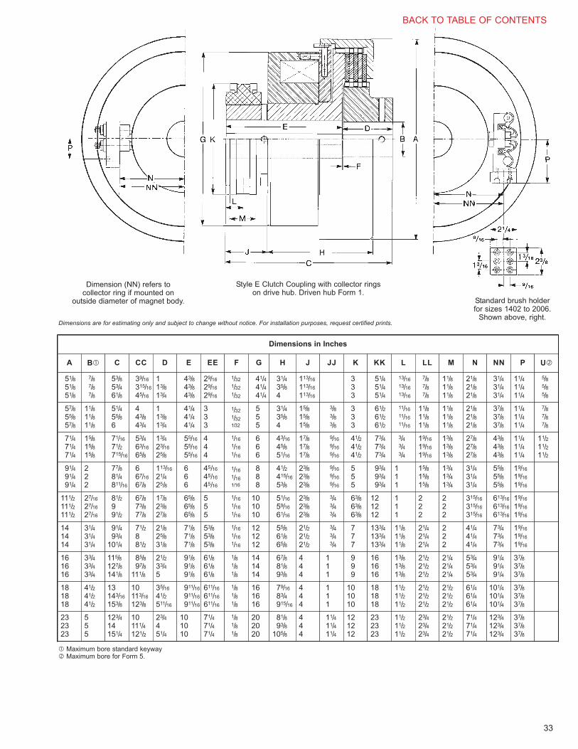
33
Dimension (NN) refers tocollector ring if mounted on
outside diameter of magnet body. Standard brush holderfor sizes 1402 to 2006.
Shown above, right.
Style E Clutch Coupling with collector ringson drive hub. Driven hub Form 1.
Dimensions are for estimating only and subject to change without notice. For installation purposes, request certified prints.
A B� C CC D E EE F G H J JJ K KK L LL M N NN P
Dimensions in Inches
U�
51/851/851/8
7/87/87/8
53/853/461/8
39/16
315/16
45/16
113/813/4
43/843/843/8
29/16
29/16
29/16
1/32
1/32
1/32
41/441/441/4
31/435/84
113/16
113/16
113/16
333
51/451/451/4
13/16
13/16
13/16
7/87/87/8
11/811/811/8
21/821/821/8
31/431/431/4
11/411/411/4
5/85/85/8
57/855/857/8
11/811/811/8
51/455/86
443/843/4
113/813/4
41/441/441/4
333
1/32
1/32
1/32
555
31/435/84
15/815/815/8
3/83/83/8
333
61/261/261/2
11/16
11/16
11/16
11/811/811/8
11/811/811/8
21/821/821/8
37/837/837/8
11/411/411/4
7/87/87/8
71/471/471/4
15/815/815/8
71/16
71/2715/16
53/463/16
65/8
13/423/16
25/8
55/16
55/16
55/16
444
1/16
1/16
1/16
666
43/16
45/851/16
17/817/817/8
9/16
9/16
9/16
41/241/241/2
73/473/473/4
3/43/43/4
19/16
19/16
19/16
13/813/813/8
27/827/827/8
43/843/843/8
11/411/411/4
11/211/211/2
91/491/491/4
222
77/881/4811/16
667/16
67/8
113/16
21/425/8
666
45/16
45/16
45/16
1/16
1/16
1/16
888
41/2415/16
53/8
23/823/823/8
9/16
9/16
9/16
555
93/493/493/4
111
15/815/815/8
13/413/413/4
31/431/431/4
55/855/855/8
19/16
19/16
19/16
111/2111/2111/2
27/16
27/16
27/16
81/2991/2
67/873/877/8
17/823/827/8
65/865/865/8
555
1/16
1/16
1/16
101010
51/16
59/16
61/16
23/823/823/8
3/43/43/4
63/863/863/8
121212
111
222
222
315/16
315/16
315/16
613/16
613/16
613/16
19/16
19/16
19/16
141414
31/431/431/4
91/493/4
101/4
71/2881/2
21/825/831/8
71/871/871/8
53/853/853/8
1/16
1/16
1/16
121212
55/861/865/8
21/221/221/2
3/43/43/4
777
133/4133/4133/4
11/811/811/8
21/421/421/4
222
41/441/441/4
73/473/473/4
19/16
19/16
19/16
161616
33/433/433/4
115/8127/8141/8
85/897/8
111/8
21/233/45
91/891/891/8
61/861/861/8
1/81/81/8
141414
67/881/893/8
444
111
999
161616
13/813/813/8
21/221/221/2
21/421/421/4
53/453/453/4
91/491/491/4
37/837/837/8
181818
41/241/241/2
13143/16
153/8
10113/16
123/8
35/16
41/2511/16
911/16
911/16
911/16
611/16
611/16
611/16
1/81/81/8
161616
79/16
83/4915/16
444
111
101010
181818
11/211/211/2
21/221/221/2
21/221/221/2
61/461/461/4
101/4101/4101/4
37/837/837/8
232323
555
123/414151/4
10111/4121/2
23/4451/4
101010
71/471/471/4
1/81/81/8
202020
81/893/8
105/8
444
11/411/411/4
121212
232323
11/211/211/2
23/423/423/4
21/221/221/2
71/471/471/4
123/4123/4123/4
37/837/837/8
� Maximum bore standard keyway� Maximum bore for Form 5.
BACK TO TABLE OF CONTENTS

34
Electrically Engaged Clutchwith Straight BoresStearns Style E, Class S Clutch is a high torque, lowinertia, electromagnetic clutch for steel mill screw-downs,ball mills, rod mills, compeg mills, kilns and similarequipment. The basic design of this clutch has beentime-tested and proven by over 50 years of successfulapplication.
The Style E, Class S Clutch is electrically engaged. Thedriven end carries the friction linings.
A spring loaded lock pin simplifies threaded adjustmentof air gap. To adjust, lock pin is depressed and armaturerotated until lock pin snaps into next slot in cage.
Friction linings can be replaced without disturbing relatedequipment on either side of the clutch.
This clutch operates on direct current. If your plant doesnot have direct current, a suitable rectifier can besupplied (see Page 48).
Class B coil insulation is standard.
Style E, Class S
ClutchSize
NominalStatic
Torque(lb-ft)
DriveEnd
Wk2 (lb-ft2)
DrivenEnd
LiningArea
(sq-in)
hp @100RPM
Approx.Shipping
(wt-lb)
Max.RPM
DynamicBalancingSuggested
above, RPM
1002 400 11.8 1.4 72 7.6 146 2300
10001004 800 13.5 2.1 144 15.0 163 2300
1006 1200 15.3 2.8 216 22.0 179 2300
1202 600 27.2 3.2 125 11.0 231 1900
10001204 1200 30.4 4.8 250 23.0 254 1900
1206 1800 33.5 6.3 375 34.0 277 1900
1402 900 56.3 6.9 166 17.0 354 1700
10001404 1800 64.5 10.0 332 34.0 395 1700
1406 2700 72.7 13.1 498 51.0 436 1700
1602 1500 103.0 10.3 212 28.0 488 1500
8001604 3000 115.0 16.0 424 57.0 540 1500
1606 4500 127.0 22.1 636 85.0 594 1500
2002 3000 270.0 21.0 320 57.0 752 1200
8002004 6000 305.0 37.2 640 114.0 853 1200
2006 9000 340.0 53.1 960 171.0 954 1200
ClutchSize
SeriesVoltage
CoilResistance
ohms
DCAmpsCoil
DCWattsCoil
600115 336 .342 40
230 1291 .178 40
800115 170 .676 80
230 666 .345 80
1000115 127 .905 104
230 509 .452 104
1200115 86 1.340 155
230 342 .672 155
1400115 67 1.720 198
230 259 .888 205
1600115 93 1.230 142
230 364 .630 146
2000115 52 2.230 256
230 200 1.150 265
ClutchSize
Series
Engagement Timein Seconds
(without controls)
1000 .21
1200 .26
1400 .31
1600 .50
2000 1.08
Performance DataMECHANICAL ELECTRICAL - Class B
ENGAGEMENT TIME
If faster time isrequired, specialcoils may besupplied for use witha forcing circuit.Consult factory fordetails.
Consult factory for modifications and/or approval drawing.
BACK TO TABLE OF CONTENTS

35
Dimensional Data (In Inches)
Size A B C D E F H S�T
(max.)U
(max.)W X Y Z AG
1002
16
153/8 123/8
81/2 5
141/8
7/16
413/32
min.419/32
max.
27/8(flatkey)
17/8
51/8
23/4
113/16 111/2 .0311004 163/8 133/8 151/8 21/2 33/4
1006 173/8 143/8 161/8 31/8 43/4
1202
161/2
167/8 137/8
83/4 51/4
155/8
7/16
425/32
min.431/32
max.
31/4
21/4
53/4
31/4
13/4 14 .0311204 177/8 147/8 165/8 27/8 41/4
1206 187/8 157/8 175/8 31/2 51/4
1402
19
1811/16 1511/16
10 61/2
177/16
7/16
511/32
min.517/32
max.
33/4
21/2
61/2
33/4
115/16 161/4 .0401404 1915/16 1615/16 1811/16 31/4 5
1406 213/16 183/16 1915/16 41/4 61/4
1602
21
195/8 165/8
11 71/2
183/8
7/16
529/32
min.63/32
max.
41/2
23/4
65/8
4
115/16 18 .0401604 207/8 177/8 195/8 31/2 51/4
1606 221/8 191/8 207/8 41/2 61/2
2002
25
211/16 181/16
13 91/2
1913/16
9/16
67/32
min.513/32
max.
5
27/8
71/2
41/4
115/16 23 .0402004 225/16 195/16 211/16 33/4 51/2
2006 239/16 209/16 225/16 41/2 63/4
� Dimension “S” gives limits on allowable end float.
Dimensions are for estimating only and subject to change without notice. For installation purposes, request certified prints.
Note: Consult factory for modifications and approval drawings.
BACK TO TABLE OF CONTENTS

36
Electrically Engaged Clutchwith Tapered BoresStearns Style E, Class S Clutch is a high torque, lowinertia, electromagnetic clutch for steel mill screw-downs,ball mills, rod mills, compeg mills, kilns and similarequipment. The basic design of this clutch has beentime-tested and proven by over 50 years of successfulapplication.
The Style E, Class S Clutch is electrically engaged. Thedriven end carries the friction linings.
A spring loaded lock pin simplifies threaded adjustmentof air gap. To adjust, lock pin is depressed and armaturerotated until lock pin snaps into next slot in cage.
Friction linings can be replaced without disturbing relatedequipment on either side of the clutch.
This clutch operates on direct current. If your plant doesnot have direct current, a suitable rectifier can besupplied (see Page 48).
Class B coil insulation is standard.
Style E, Class S
ClutchSize
NominalStatic
Torque(lb-ft)
DriveEnd
Wk2 (lb-ft2)
DrivenEnd
LiningArea
(sq-in)
hp @100RPM
Approx.Shipping
(wt-lb)
Max.RPM
DynamicBalancingSuggested
above, RPM
1002 400 11.8 1.4 72 7.6 146 2300
10001004 800 13.5 2.1 144 15.0 163 2300
1006 1200 15.3 2.8 216 22.0 179 2300
1202 600 27.2 3.2 125 11.0 231 1900
10001204 1200 30.4 4.8 250 23.0 254 1900
1206 1800 33.5 6.3 375 34.0 277 1900
1402 900 56.3 6.9 166 17.0 354 1700
10001404 1800 64.5 10.0 332 34.0 395 1700
1406 2700 72.7 13.1 498 51.0 436 1700
1602 1500 103.0 10.3 212 28.0 488 1500
8001604 3000 115.0 16.0 424 57.0 540 1500
1606 4500 127.0 22.1 636 85.0 594 1500
2002 3000 270.0 21.0 320 57.0 752 1200
8002004 6000 305.0 37.2 640 114.0 853 1200
2006 9000 340.0 53.1 960 171.0 954 1200
ClutchSize
SeriesVoltage
CoilResistance
ohms
DCAmpsCoil
DCWattsCoil
1000115 127 .905 104
230 509 .452 104
1200115 86 1.340 155
230 342 .672 155
1400115 67 1.720 198
230 259 .888 205
1600115 93 1.230 142
230 364 .630 146
2000115 52 2.230 256
230 200 1.150 265
ClutchSize
Series
Engagement Timein Seconds
(without controls)
1000 .21
1200 .26
1400 .31
1600 .50
2000 1.08
Performance DataMECHANICAL ELECTRICAL - Class B
ENGAGEMENT TIME
If faster time isrequired, specialcoils may besupplied for use witha forcing circuit.Consult factory fordetails.
BACK TO TABLE OF CONTENTS

37
Dimensional Data (In Inches)
Mill MotorFrame Size
Size A B C D E F H S� T�(± 1/32)
U� WD X Y Z KeywayAG
8026021002
16
153/4 123/4 81/2
93/4
9 5
141/2
7/16
413/32
min.419/32
max.
47/8
45/8
13/4 31/4
4
31/2
3 11/8
13/16
11/16 111/2
1/2 ξ 1/4
1/2 ξ 1/4
1/2 ξ 1/4
1/2 ξ 1/4
3/4 ξ 1/4
3/4 ξ 1/4
.031803
804
603
6041004 193/8 163/8 181/8 2 31/2
8066061006 195/8 165/8 183/8 21/2 4
803
804
603
6041202
161/2
167/8 137/8 9
12
1151/4
155/8
7/16
425/32
min.431/32
max.
47/8
2 31/2
51/4
5
31/2 1
13/8
11/414 .032
8086081204 193/8 163/8 181/8 3 41/2
8106101206 195/8 165/8 183/8 31/4 41/2
8066061402
19
1811/16 1511/16 93/4
131/8
12 61/2
177/16
7/16
511/32
min.517/32
max.
57/16
21/2 4
55/8
51/4
4 11/8
11/2
13/8 161/4
1/2 ξ 1/4
3/4 ξ 1/4
3/4 ξ 1/4.0408106101404 203/16 173/16 1815/16 31/4 41/2
8126121406 217/16 187/16 203/16 35/8 5
8086081602
21
201/2 171/2 11
141/2
131/8 71/2
191/4
7/16
529/32
min.63/32
max.
6
3 5
61/2
55/8
41/2 11/4
15/8
11/2 18
3/4 ξ 1/4
3/4 ξ 1/4
3/4 ξ 1/4.0408126121604 22 19 203/4 35/8 5
8146141606 221/4 191/4 21 41/4 5
8126122002
25
225/16 195/16 131/8
171/2
153/4 91/2
211/16
9/16
67/32
min.613/32
max.
65/16
35/8 55/8
71/2
7
5 11/2
15/16
13/4 23
3/4 ξ 1/4
11/4 ξ 1/2
11/4 ξ 3/8.0408166162004 2313/16 2013/16 229/16 45/8 51/2
8186182006 2315/16 2015/16 2211/16 5 6
� Dimension “S” gives limits on allowable end float.� Dimension “T” is minimum - if to be greater, add to driven hub “Y” dimension only.� Note - if bore is to be larger than “U”, consult factory.
Dimensions are for estimating only and subject to change without notice. For installation purposes, request certified prints.
Note: Housing sold separately.
Note: Consult factory for modifications and approval drawings.
BACK TO TABLE OF CONTENTS

38
Electrically Engaged ClutchStearns Style E, Class M Clutch is a high torque, low inertia, electromagnetic clutch for steel mill screw-downs, ball mills, rod mills, compeg mills, kilns and similar equipment. The basic design of this clutch has been time-tested and proven by over 50 years of successful application. The Style E, Class M Clutch is electrically engaged. The driven end carries the friction linings.A spring loaded lock pin simplifies threaded adjustment of air gap. To adjust, lock pin is depressed and armature rotated until lock pin snaps into next slot in cage.Friction linings can be replaced without disturbing related equipment on either side of the clutch.This clutch operates on direct current. If your plant does not have direct current, a suitable rectifier can be supplied (see Page 48).Class B coil insulation is standard.
Style E, Class M
Performance DataMECHANICAL ELECTRICAL - Class B
Clutch Size
Nominal Static
Torque (lb-ft)
Wk2 (lb-ft2) Lining Area
(sq-in)
Approx. Shipping Weight
Max. RPMDrive
EndDriven
End
2002 3000 333 36 320 990 900
2004 6000 359 51 640 1100 900
2006 9000 385 66 960 1210 900
2402 6400 682 70 425 1660 800
2404 12800 762 109 850 1840 800
2406 19200 842 149 1275 2020 800
2802 10000 1332 131 540 2280 700
2804 20000 1508 213 1080 2565 700
2806 30000 1684 295 1620 2850 700
3202 15000 2820 345 848 3620 600
3204 30000 3315 535 1696 4160 600
3206 45000 3810 725 2544 4700 600
4202 40000 8300 709 1626 8400 400
4204 80000 9150 1200 3252 9300 400
4206 120000 10000 1700 4878 10200 400
Clutch Size
SeriesVoltage
Coil Resistance
ohms
DC Amps Coil
DC Watts Coil
2000115 52.5 2.20 253
230 200 1.15 265
2400115 46.9 2.45 281
230 95 2.4 550
2800115 41.1 2.80 322
230 136 1.68 390
3200115 35.3 3.25 374
230 138 1.66 382
4200115 24.7 4.66 536
230 96.0 2.39 551
BACK TO TABLE OF CONTENTS

39
Dimensional Data (In Inches)
Dimensions are for estimating only and subject to change without notice. For installation purposes, request certified prints.
Note: Consult factory for modifications and approval drawings.
Size A B (max) C D E G H J K L M N Q R S T
2002 23 5 231/4 71/2 81/4 20 715/16 715/32 14 23/4 4 711/16 101/2 8 8 91/4
2004 23 5 241/2 71/2 91/2 20 93/16 715/32 14 23/4 4 711/16 101/2 8 8 101/2
2006 23 5 253/4 71/2 103/4 20 107/16 715/32 14 23/4 4 711/16 101/2 8 8 113/4
2402 283/4 63/4 281/8 9 101/8 24 929/32 815/16 14 315/16 53/16 711/16 101/2 8 8 111/8
2404 283/4 63/4 291/2 9 111/2 24 119/32 815/16 14 315/16 53/16 711/16 101/2 8 8 121/2
2406 283/4 63/4 307/8 9 127/8 24 1221/32 815/16 14 315/16 53/16 711/16 101/2 8 8 137/8
2802 323/4 71/2 301/8 91/2 111/8 28 103/4 97/16 14 35/8 47/8 711/16 101/2 8 8 123/8
2804 323/4 71/2 315/8 91/2 125/8 28 121/4 97/16 14 35/8 47/8 711/16 101/2 8 8 137/8
2806 323/4 71/2 331/8 91/2 141/8 28 133/4 97/16 14 35/8 47/8 711/16 101/2 8 8 153/8
3202 37 9 343/4 11 123/16 32 12 1015/16 19 4 53/8 103/16 13 101/2 101/2 137/16
3204 37 9 3611/16 11 1411/16 32 141/2 1015/16 19 4 53/8 103/16 13 101/2 101/2 1515/16
3206 37 9 393/16 11 173/16 32 17 1015/16 19 4 53/8 103/16 13 101/2 101/2 187/16
4202 47 14 467/8 15 167/8 42 165/8 1415/16 24 4 53/8 1211/16 151/2 13 13 181/8
4204 47 14 493/8 15 193/8 42 191/8 1415/16 24 4 53/8 1211/16 151/2 13 13 205/8
4206 47 14 517/8 15 217/8 42 215/8 1415/16 24 4 53/8 1211/16 151/2 13 13 231/8
BACK TO TABLE OF CONTENTS

40
Spring Engaged Clutch withStraight BoresStearns Style SCE, Class S3 Clutch is a high torque, lowinertia, electromagnetic clutch for steel mill screw-downs,and similar equipment. The basic design of this clutchhas been time-tested and proven by over 50 years ofsuccessful application.
Stearns S3 Clutch is designed to provide extremely highcapacity in a relatively small package.
The Style SCE, Class S3 Clutch is spring engaged,electromagnetically released. A spring loaded lock pinsimplifies adjustment of air gap. When adjustment isrequired, lock pin is depressed and wear adjustment ringrotated until lock pin snaps into next slot in cage.
Friction linings can be quickly replaced without disturbingrelated equipment on either side of the clutch.
This clutch operates on direct current and requiresforcing circuit (see Page 49 or Wiring Diagram). If yourplant does not have direct current, a suitable combinationforcing circuit/rectifier can be supplied.
Class B coil insulation is standard.
Style SCE, Class S3
ClutchSize
NominalStatic
Torque(lb-ft)
DriveEnd
Wk2 (lb-ft2)
DrivenEnd
RPM at whichDynamic
Balancing isRequired
Approx.Shipping(wt-lbs)
Max.RPM
802 450 6.90 .60 1200 115 3600
804 900 7.20 .80 1200 130 3600
1004 1400 17.25 1.45 1200 200 3300
1006 2100 18.20 1.90 1200 210 3300
1204 3500 46.75 3.50 1000 330 2000
1206 5000 49.20 4.65 1000 350 2000
1406 7800 100.70 11.40 1000 550 1800
1606 12000 187.30 20.80 800 700 1600
SeriesResistor
wattohms
SourceLine
Voltage
ClutchSize
CoilResistance
ohms Inrush
DC Watts Circuit
Holding
125275230800 130 407W-1.77A 130W-.567A
2001552301000 82 643W-2.8A 223W-.97A
2501252301200 58.4 910W-3.95A 288W-1.25A
2501352301400 60.8 870W-3.78A 269W-1.17A
2001352301600 59.4 890W-3.87A 272W-1.18A
Performance DataMECHANICAL ELECTRICAL
BACK TO TABLE OF CONTENTS

41
Dimensional Data (In Inches)
� “D” is minimum - larger size to suit customer.� If bore is to be larger than “U”, consult factory.Note: Wk2 on drive and driven end are calculated for maximum “U” bore (as shown in Table).
Dimensions are for estimating only and subject to change without notice. For installation purposes, request certified prints.
Note: Consult factory for modifications and approval drawings.
Size A B C D� E F H S Z AE AF AGU� X
Drive Hub
Keyway U� X
Driven Hub
Keyway
802151/2
141/2 111/281/4 43/4
131/47/16 41/8 101/8 13/4 21/2 .050 21/2 41/4 5/8 x 5/16 23/4
31/85/8 ξ 5/16
804 15 12 133/4 35/8
1004161/2
173/8 143/883/4 51/4
161/87/16 45/8 12 17/8 21/2 .060 3 53/8 3/4 x 3/8 31/4
43/83/4 ξ 3/8
1006 18 15 163/4 5
120419
199/16 161/16
10 61/2185/16
9/16 57/16 141/2 21/16 21/2 .060 4 57/8 33/443/4
1206 203/16 1611/16 1815/16
1 x 1/253/8
7/8 ξ 7/16
1406 20 237/8 203/8 101/2 7 225/8 9/16 71/4 163/4 21/16 21/2 .060 4 61/8 1 x 1/2 43/4 7 11/4 ξ 5/8
1606 22 243/8 207/8 111/2 8 231/8 9/16 63/4 19 21/16 21/2 .060 43/4 71/8 11/4 x 5/8 51/2 73/4 11/4 ξ 5/8
Wiring Diagram (R) is a normally open, single pole, DC contactor.(TD) is a normally closed time delay relay.
To release the clutch, the three pole contactor is closed. This closes (R)contacts and applies full line voltage to clutch coil. After a few secondsinterval, time delay relay opens contactor (R) and places resistor in serieswith the clutch coil, reducing voltage imposed on coil from line voltage tolower holding voltage.
To engage the clutch, the contactor is opened. The back (EMF) generatedin the clutch coil is dissipated through the surge suppressing rectifier,protecting the coil and lead wire insulation and minimizing arcing at thecontacts.
Note: Housing sold separately.
BACK TO TABLE OF CONTENTS

42
Spring Engaged Clutch withTapered BoresStearns Style SCE, Class S3 Clutch is a high torque, lowinertia, electromagnetic clutch for steel mill screw-downs,and similar equipment. The basic design of this clutchhas been time-tested and proven by over 50 years ofsuccessful application.
Stearns S3 Clutch is designed to provide extremely highcapacity in a relatively small package.
The Style SCE, Class S3 Clutch is spring engaged,magnetically released. A spring loaded lock pin simplifiesadjustment of air gap. When adjustment is required, lockpin is depressed and wear adjustment ring rotated untillock pin snaps into next slot in cage.
Friction linings can be quickly replaced without disturbingrelated equipment on either side of the clutch.
This clutch operates on direct current and requiresforcing circuit (see Page 49 or Wiring Diagram). If yourplant does not have direct current, a suitable combinationforcing circuit/rectifier can be supplied.
Class B coil insulation is standard.
Style SCE, Class S3
ClutchSize
NominalStatic
Torque(lb-ft)
DriveEnd
Wk2 (lb-ft2)
DrivenEnd
RPM at whichDynamic
Balancing isRequired
Approx.Shipping(wt-lbs)
Max.RPM
802 450 6.90 .65 1200 115 3600
804 900 7.20 .85 1200 130 3600
1004 1400 17.25 1.80 1200 200 3300
1006 2100 18.20 2.20 1200 210 3300
1204 3500 46.75 3.70 1000 330 2000
1206 5000 49.20 4.60 1000 350 2000
1406 7800 100.70 9.75 1000 550 1800
1606 12000 187.30 18.20 800 700 1600
SeriesResistor
wattohms
SourceLine
Voltage
ClutchSize
CoilResistance
ohms Inrush
DC Watts Circuit
Holding
125275230800 130 407W-1.77A 130W-.567A
2001552301000 82 643W-2.8A 223W-.97A
2501252301200 58.4 910W-3.95A 288W-1.25A
2501352301400 60.8 870W-3.78A 269W-1.17A
2001352301600 59.4 890W-3.87A 272W-1.18A
Performance DataMECHANICAL ELECTRICAL
BACK TO TABLE OF CONTENTS

43
Dimensional Data (In Inches)
Dimensions are for estimating only and subject to change without notice. For installation purposes, request certified prints.
Note: Consult factory for modifications and approval drawings.
Size A CB D E F H S T� Z AE AF AG U� X Y WD Keyway
602 802
151/2
123/8153/8 73/8
43/4
141/8
7/16 41/8
41/2
101/8 13/4
21/2
.050
13/4 3 � 31/4
1/2 ξ 1/4
802 603 803131/4161/4
81/415 41/4 2 31/2 11/16 31/2
604 804 83/4
602 802 123/8153/8 73/8 141/8 41/2 13/4 3 � 31/4
804 603 803131/4161/4
81/415 41/4 2 31/2 11/16 31/2
604 804 83/4
1004606 806
161/2
1518 93/4
51/4
163/4
7/16 45/8 43/4 12 13/4 .060
21/2 4 13/16 4 1/2 ξ 1/4
608 808 161/4191/4 11 18 3 41/2 15/16 5 3/4 ξ 1/4
1006606 806 1518 93/4 163/4 21/2 4 13/16 4 1/2 ξ 1/4
608 808 161/4191/4 11 18 3 41/2 15/16 5 3/4 ξ 1/4
1204610 810
19
175/162013/16 12
61/2
199/16
9/16 57/16 59/16 141/2 2 .060
31/4 41/2 17/16 51/4
3/4 ξ 1/4612 812 189/16221/16 131/8 2013/16 35/8 5 19/16 55/8
1206610 810 175/162013/16 12 199/16 31/4 41/2 17/16 51/4
612 812 189/16221/16 131/8 2013/16 35/8 5 19/16 55/8
1406 614 814 20 205/8241/8 141/2 7 227/8 9/16 71/4 73/8 163/4 21/8 .060 41/4 5 111/16 61/2 1 ξ 3/8
1606616 816
22213/8247/8 153/4 235/8
9/16 63/4 19 21/8 .06045/8 51/2 113/16 7 11/4 ξ 3/8
618 818 211/225 171/28
233/467/8
5 6 13/8 71/2 11/4 ξ 1/2
Mill MotorFrame Size�
� Indicates motor shaft size which clutch will accommodate. Clutch selection should be based on application requirements, not motor frame size.� Dimension “T” is minimum - if to be greater, add to driven hub.� Note - if bore is to be larger than “U”, consult factory.� Dimension “Y” drive end (11/4”), dimension “Y” driven end (1”).
Wiring Diagram (R) is a normally open, single pole, DC contactor.(TD) is a normally closed time delay relay.
To release the clutch, the three pole contactor is closed. This closes (R)contacts and applies full line voltage to clutch coil. After a few secondsinterval, time delay relay opens contactor (R) and places resistor in serieswith the clutch coil, reducing voltage imposed on coil from line voltage tolower holding voltage.
To engage the clutch, the contactor is opened. The back (EMF) generatedin the clutch coil is dissipated through the surge suppressing rectifier,protecting the coil and lead wire insulation and minimizing arcing at thecontacts.
BACK TO TABLE OF CONTENTS

44
Spring Engaged BrakeStearns Style SCEB, Class S3 Brake is a high torque,low inertia, electromagnetic brake for steel mill screw-downs, and similar equipment. The basic design of thisbrake has been time-tested and proven by over 50 yearsof successful application.
Stearns SCEB Brake is designed to provide extremelyhigh capacity in a relatively small package for end shaftmounting.
The Style SCEB, Class S3 Brake is spring engaged,magnetically released. A spring loaded lock pin simplifiesadjustment of air gap. When adjustment is required, lockpin is depressed and wear adjustment ring rotated untillock pin snaps into next slot in cage.
Friction linings can be quickly replaced without disturbingrelated equipment.
This brake operates on direct current and requiresforcing circuit (see Page 49 or Wiring Diagram). If yourplant does not have direct current, a suitable rectifier canbe supplied.
Class B coil insulation is standard.
Style SCEB, Class S3
BrakeSize
NominalStatic
Torque(lb-ft)
Wk2 (lb-ft2)Approx.Shipping(wt-lbs)
Max.RPM
802 450 .36 86 3600
804 900 .53 97 3600
1004 1400 1.35 170 3600
1006 2100 1.85 180 3600
1204 3500 2.10 270 2400
1206 5000 4.35 280 2400
1406 7800 10.70 370 2000
1606 12000 19.00 660 1800
SeriesResistor
wattohms
SourceLine
Voltage
BrakeSize
CoilResistance
ohmsInrush
DC Watts Circuit
Holding
125275230800 130 407W-1.77A 130W-.567A
2001552301000 82 643W-2.8A 223W-.97A
2501252301200 58.4 910W-3.95A 288W-1.25A
2501352301400 60.8 870W-3.78A 269W-1.17A
2001352301600 59.4 890W-3.87A 272W-1.18A
Performance DataMECHANICAL ELECTRICAL
BACK TO TABLE OF CONTENTS

45
Dimensional Data (In Inches)
Dimensions are for estimating only and subject to change without notice. For installation purposes, request certified prints.
804, 1004 flange mount SCEB specification print available. Consult Stearns Division
� Dimension “U” is maximum with standard key. If “U” bore is to be larger, consult factory.
Wiring Diagram (R) is a normally open, single pole, DC contactor.(TD) is a normally closed time delay relay.
To release the brake, the three pole contactor is closed. This closes (R)contacts and applies full line voltage to brake coil. After a few secondsinterval, time delay relay opens contactor (R) and places resistor in serieswith the brake coil, reducing voltage imposed on coil from line voltage tolower holding voltage.
To engage the brake, the contactor is opened. The back (EMF) generatedin the brake coil is dissipated through the surge suppressing rectifier,protecting the coil and lead wire insulation and minimizing arcing at thecontacts.
Size A B C D E F G H J K L M N P R S AG AF U� X Keyway
802111/2
129/32 67/16
51/2 5 21/2 3/8 9/16 2 35/8 9/16 51/16 47/16 30° 21/32 11/16 .050 4 23/421/4
5/8 ξ 5/16
804 213/32 615/16 23/4
100414
23/4 77/863/4 6 3 1/2 11/16 21/2 43/8 11/16 61/16 51/2 221/2° 21/8 7/8 .060 41/4 31/4
31/43/4 ξ 3/8
1006 33/8 81/2 37/8
120416
213/16 815/16
8 7 31/2 3/4 13/16 3 51/2 1 71/4 61/2 45° 25/8 11/2 .060 47/8 33/431/2
7/8 ξ 7/16
1206 37/16 99/16 41/8
1406 181/4 41/32 129/16 9 8 41/2 3/4 11/16 33/8 7 11/4 81/2 73/4 15° 41/32 23/4 .060 63/8 43/4 51/4 11/4 ξ 5/8
1606 21 325/32 123/8 10 9 51/2 1 15/16 4 81/4 13/8 95/8 85/8 45° 33/32 13/32 .060 61/2 51/2 51/2 11/4 ξ 5/8
BACK TO TABLE OF CONTENTS

46
For Convenience, Safety and Energy Savings,Look to Stearns® Rectifier Controls.
Perfectly matched to StearnsDC actuated clutches, brakes orcombination units, Stearnsrectifier controls offer solid-statereliability that also takes intoaccount important human usefactors, making them easy toutilize and maintain.
Stearns rectifier controls areavailable in fixed or adjustableoutput models with compacthousings to simplifyinstallation.
For ultimate convenience, allwiring connections are readily
accessible. The PR Series evengoes one step further, offering theease of modular plug-in designsconnecting directly to octalsockets.
For safety, all models offeredare fused to provide protectionagainst overload and featurean arc suppression circuit,minimizing arcing and extendingcontact life. In the PR Series, theinternal fuse can be changed onlyby removing the rectifier from itssocket - eliminating a potentialshock hazard.
For energy savings, efficiencyis built into Stearns rectifiers. Theadjustable voltage output on thePR-33, for example, usesthyristor control for a low 4-wattpower loss-87% less than somecompetitive units.
When you need reliableperformance and more, look toStearns rectifier controls.
BACK TO TABLE OFCONTENTS

DiscountSymbol
X-1
47
Model PR-01Two fixed 100 volt outputs.• Modular plug-in design uses octal socket for easy
mounting and wiring connection.
• Internally fused for overload protection.
• Operates one clutch or one brake, or both, one onat a time.
Model PR-33One fixed 100 volt output and one adjustable 15-100volt output to allow reduced torque starts or stops for“soft” cushioned engagement.• Adjustable control on top of housing for easy
accessibility.
• Modular plug-in design uses octal socket for eachmounting and wiring connection.
• Internally fused for overload protection.
• Operates one clutch or one brake, or both, one onat a time.
Rectifier Controls
Performance/List Price Data
List Price Data
Octal Socket(s)Supplied with terminalscrews and clips
RectifierPart
Number
ACInput
Voltage
Nominal DC Output Control CircuitsSwitching
Relay
ListPrice��Volts
Max.Amp��
Max.Watts
#1 #2
PR-014-1-20001-00
11550-60 Hz
100 1.0 100 Fixed Fixed No $266.00
PR-334-1-20033-00
11550-60 Hz
15-100 0.5 50 Fixed Variable No 642.00
Enclosure dimensions applyto both PR-01 and PR-33.
�� Based on ambient temperature of 104°F.��List prices subject to change without notice.
Part Number: 9-61-0153-00Dimensions
Part Number: 9-61-0153-01Dimensions
Octal SocketPart Number
DiscountSymbol
List Price
9-61-0153-00 X-1$128.00
9-61-0153-01 X-148.00
X-1
BACK TO TABLE OF CONTENTS

48
Series 12000 Silicon RectifiersHeavy duty single-phase rectifier for use withStearns heavy duty clutches and brakes.Incorporates a solid-state silicon bridge circuit forhigh efficiency and excellent voltage regulation.Available with outputs of 115 or 230 Vdc; powerratings of up to 1150 watts. A transformer providesisolation and dual AC input capability… 115/230 or230/460 Vac. Each rectifier is housed in a NEMA 1steel cabinet and includes a separately housedmanual starter with overload heaters.
Rectifier Controls
Wiring Diagram
Dimensional Data
Performance Data
StockNumber
AC Input(50/60 Hz
Single-Phase)DC Output
Volts Amps Volts Amps� Watts
4-1-12102-00 115/230 2.5/1.3 115 2.0 230
4-1-12104-00 115/230 6.4/3.2 115 5.0 575
4-1-12202-00 230/460 1.3/0.7 115 2.0 230
4-1-12205-00 230/460 3.2/1.6 115 5.0 575
4-1-12302-00 115/230 5.2/2.6 230 2.0 460
4-1-12305-00 115/230 13.0/6.5 230 5.0 1150
4-1-12402-00 230/460 2.6/1.3 230 2.0 460
4-1-12405-00 230/460 6.4/3.2 230 5.0 1150
� Based on ambient temperature of 104°F.
BACK TO TABLE OF CONTENTS

49
Combination forcing circuit and rectifier for use withStearns SCE spring-set clutches and SCEB spring-set brakes. Suitable for use with all sizes from 800through 1600. Provides the momentary forcingvoltage necessary to release a clutch or brake. Unitsare available for 115, 208, 230, 460 and 575 Vac,50/60 Hz input. The output of each unit is a forcingvoltage of 230 Vdc which, after a 5 second delay,drops to a holding voltage of 70 Vdc. Circuitryincludes surge suppression network to protect coiland minimize contact arcing. Complete circuit ishoused in a NEMA 12 enclosure.
Forcing Circuits
Wiring Diagram
Dimensional Data
Performance Data
StockNumber
AC InputVoltage50/60 Hz
ForcingVolts
HoldingVolts
DC Input
Watts
Approx.ShippingWt. (lbs.)
4-3-00115-12 115 Vac 230 70 1000 60
4-3-00208-12 208 Vac 230 70 1000 60
4-3-00230-12 230 Vac 230 70 1000 60
4-3-00460-12 460 Vac 230 70 1000 60
4-3-00575-12 575 Vac 230 70 1000 60
BACK TO TABLE OF CONTENTS

Application Engineering Data
50
BACK TO TABLE OF CONTENTS
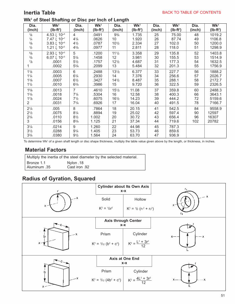
Multiply the inertia of the steel diameter by the selected material.
Bronze 1.1 Nylon .18Aluminum .35 Cast iron .92
Material Factors
51
Inertia Table
Wk2 of Steel Shafting or Disc per Inch of Length
Radius of Gyration, Squared
Dia.(inch)
Wk2
(lb-ft2)Dia.
(inch)Wk2
(lb-ft2)Dia.
(inch)Wk2
(lb-ft2)Dia.
(inch)Wk2
(lb-ft2)Dia.
(inch)Wk2
(lb-ft2)1/81/43/81/2
4.53 ξ 10-8
7.47 ξ 10-7
3.83 ξ 10-6
1.21 ξ 10-5
441/441/243/4
.0491
.0626
.0787
.0977
93/410101/211
1.7351.9202.3342.811
25262728
75.0087.74
102.0118.0
48495051
1019.21106.81200.01298.9
5/83/47/8
1
2.93 ξ 10-5
6.07 ξ 10-5
.0001
.0002
551/451/253/4
.1200
.1458
.1757
.2099
111/212121/213
3.3583.9814.6875.484
29303132
135.8155.5177.3201.3
52535455
1403.81514.91632.51756.9
11/811/413/811/2
.0003
.0005
.0007
.0010
661/461/263/4
.2488
.2930
.3427
.3986
131/214141/215
6.3777.3768.4879.720
33343536
227.7256.6288.1322.5
56575859
1888.22026.72172.72326.5
15/813/417/82
.0013
.0018
.0024
.0031
771/471/273/4
.4610
.5304
.6075
.6926
151/216161/217
11.0812.5814.2316.04
37383940
359.8400.3444.2491.5
60667278
2488.33643.15159.67166.7
21/421/223/43
.005
.0075
.0110
.0156
881/481/283/4
.7864
.88941.0021.125
18192021
20.1525.0230.7237.34
41424344
542.5597.4656.4719.6
849096
102
9558.9125971630720782
31/431/233/4
.0214
.0288
.0380
991/491/2
1.2601.4051.564
222324
44.9853.7363.70
454647
787.3859.6936.9
To determine Wk2 of a given shaft length or disc shape thickness, multiply the table value given above by the length, or thickness, in inches.
Cylinder about Its Own Axisx-x
Axis through Centerx-x
Axis at One Endx-x
Solid Hollow
Cylinder
Prism Cylinder
Prism
K2 = 1/2r2 K2 = 1/2 (r12 + r2
2)
K2 = 1/12 (b2 + c2)
K2 = 1/12 (4b2 + c2)
K2 =L2 + 3r2
12
K2 =4L2 + 3r2
12
BACK TO TABLE OF CONTENTS

52
English-Metric Conversion FactorsMultiply the base unit by the factor shown to obtain the desired conversion
Conversion Factors forThermal Capacity
Metric Bore andKeyways
Contact factory for specificapplication information
ft-lb/minft-lb/minft-lb/minft-lb/min
33,000550777.385
44.254
horsepowerhp-sec/minBTU/min
watts
To ObtainMultiply byBase Unit
8 ξ 730
8 ξ 728
8 ξ 726
8 ξ 725
8 ξ 724
6 ξ 622
6 ξ 620
6 ξ 619
6 ξ 618
5 ξ 516
5 ξ 515
5 ξ 514
4 ξ 412
3 ξ 310
2 ξ 28
2 ξ 26
Keyway(millimeter)
Nominal
Bore(millimeter)+ .25 mm- .000 mm
Temperaturedegrees Celcius, °Cdegrees Fahrenheit, °F
(°F - 32) × 5/9(°C × 9/5) + 32
degrees Fahrenheit, °Fdegrees Celcius, °C
12.42833horsepower-seconds per minute,hp-sec/min
Thermal capacity
kilowatt, kWhorsepower, hp
.74571.341
horsepower, hpkilowatt, KwHorsepower (English)
kilogram, kgpound, lb
.4535922.20462
pound, lbkilogram, kgWeight
joule, Jfoot-pound, ft-lb
1.355818.73756
foot-pound, ft-lbjoule, JKinetic energy
kilogram-meter squared, kgm2
pound-feet squared, lb-ft2.042
23.81pound-feet squared, lb-ft2
kilogram-meter squared, kgm2Moment of Inertia
newton-meter, Nmpound-inch, lb-innewton-meter, Nmpound-feet, lb-ftnewton-meter, Nmounce-inch, oz-in
.1129858.85071.355818
.73756
.007062141.612
pound-inch, lb-innewton-meter, Nmpound-feet, lb-ftnewton-meter, Nmounce-inch, oz-innewton-meter, Nm
Torque
millimeter, mminch, in
25.4.03937
inch, inmillimeter, mmLength
ConversionFactorBase UnitMeasurement
watts, W
horsepower-seconds per minutehp-sec/min
.08046watts, W
BACK TO TABLE OF CONTENTS