CloudScape ® VR Visidyne, Inc. 5951 Encina Road, Suite 208 Goleta, CA 93117 805-683-4277 (voice)...
61
CloudScape CloudScape ® ® VR VR Visidyne, Inc. 5951 Encina Road, Suite 208 Goleta, CA 93117 805-683-4277 (voice) 805-683-5377 (fax) [email protected] (e-mail) September 1999 Prepared by John DeVore, Ken Sartor and Tim Stephens Applied Physics Group, Visidyne, Inc. Visidyne, Inc. 3322 South Memorial Pkwy, Suite 223 Huntsville, AL 35801 256-880-3411 (voice) 256-880-3284 (fax) [email protected] (e-mail) A current version of this briefing is available at ftp.visidyne.com/ cloud
-
Upload
timothy-rogers -
Category
Documents
-
view
214 -
download
0
Transcript of CloudScape ® VR Visidyne, Inc. 5951 Encina Road, Suite 208 Goleta, CA 93117 805-683-4277 (voice)...

CloudScapeCloudScape®® VR VR
Visidyne, Inc.5951 Encina Road, Suite 208
Goleta, CA 93117805-683-4277 (voice) 805-683-5377 (fax)
[email protected] (e-mail)
September 1999
Prepared by
John DeVore, Ken Sartor and Tim Stephens
Applied Physics Group, Visidyne, Inc.
Visidyne, Inc.3322 South Memorial Pkwy, Suite 223
Huntsville, AL 35801256-880-3411 (voice) 256-880-3284 (fax)
[email protected] (e-mail)
A current version of this briefing is available atftp.visidyne.com/cloud

2
Briefing Overview
Who is Visidyne? What is CloudScape® VR?
– API for Vega™ development system
– Sample CloudScape® VR images How does CloudScape® VR Work?
– Rendering
– Databases
– Validation How can I get cloud databases? What are the CloudScape® VR Development Plans? Where can I find technical references?

3
Who is Visidyne?
4
Who is Visidyne?
A small business Headquarters in Burlington, MA
– Offices in Santa Barbara, CA, Huntsville, AL and Parsippany, NJ Founded in 1969 Provides engineering services,
instrumentation and software products Nationally-recognized capability in several key
defense technologies– Atmospheric physics
– Battlefield and battlespace environments
– Optical sensor systems 60+ staff
– Dr. Jack Carpenter, President
– Dr. Tim Stephens, Vice President and Manager, Applied Physics Group
– Dr. John DeVore, Manager, Computer Visualization Program
– Dr. Jim Thompson, Radiative Transfer
– Dr. Ken Sartor, Real-time Visualization

5
Silicon Graphics
Optics
Modeling &
Simulation
Measurements&
Analysis
Instrumentation&
Fabrication
Visidyne Technical Focal Points

6
Visidyne Applied Physics Group Customers
Major U.S. Department of Defense (DoD) Customers– Defense Threat Reduction Agency (formerly DNA)
– Ballistic Missile Defense Organization
– U.S. Air Force Research Laboratory
– U.S. Army Space and Missile Defense Command Major Industrial Customers
– Nichols Research Corporation (Huntsville, AL)
– Photon Research Associates (La Jolla, CA)
– Kaman Sciences Corporation (Colorado Springs, CO) Small Business Innovative Research Program
– Cloud prediction and classification
– Real-time simulation
– DIS / HLA interactive simulation environment
– Ground target BRDF modeling
7
What is CloudScape® VR?
1. API for Vega™ development system

8
CloudScape® VRA Vega™ module for
– weather clouds, – battlefield effects, and
– other atmospheric obscurants
QuantitativePhysics-Based Background and Obscuration Prediction
3 - DFaceted Representation
of Cloud Regions
Real TimeSupport for Simulation
and Virtual Reality
Multi-SpectralVisible, IR and UV Bands
What is CloudScape® VR?
CloudScape® VR is available for purchase from MultiGen-Paradigm, Inc.
9
USAF CloudScape®
High-fidelity Fixed-frame Images
CloudScape® VR
Real-time Simulation and Training
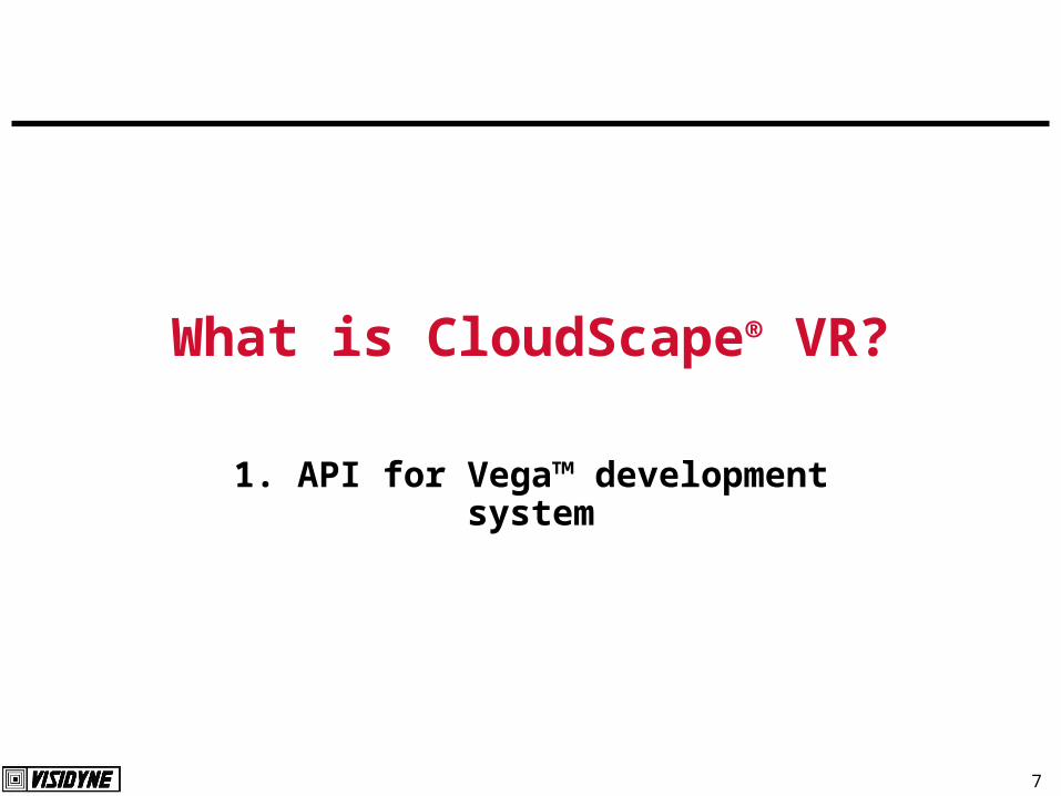
CloudScape® VR built via Technology Transfer
Technology originally developed for US Air Force Research Laboratory to complement CSSM cloud-microphysics predictions
USAF CloudScape– Pixel-by-pixel calculation of background radiance and obscuration– Numerical integration along each line of sight
CloudScape VR uses two approximations for real-time performance– Database of azimuth/elevation samples is interpolated at vertices– Gouraud-shading by graphics engine interpolates between vertices

10
A Vega™ module for radiometric visualization of
diffuse, translucent atmospheric (cloud) phenomena
How do you use CloudScape® VR?
An API library with a LynX™ panel
For use with Vega™
– To generate virtual-reality environments including clouds
– Real-time “out-the-window” view with
Quantitative cloud-obscuration of backgrounds
Semi-quantitative images of cloud-radiance
For optional use with SensorVision™
– To generate radiometric (quantitative) virtual-reality environments
Backgrounds and obscuration
– SensorVision™ for solid objects, CloudScape® for diffuse objects

11
CloudScape® VR Features
3-D faceted cloud descriptions
Calibrated fog function
Full bi-directional-radiance computation
– Arbitrary solar (lunar) illumination angle
– Arbitrary viewing geometry
Any waveband (visible, infrared, ultraviolet)

12
CloudScape® VR LynX™ Panel

13
CloudScape® VR
SensorVision™
Vega™
Performer™
OpenGL®
User Application
SGI IRIX™
Planned
Windows NT®
OpenGL®
Vega™ NT
CloudScape® VR Libraries in Simulation Hierarchy

14
What is CloudScape® VR?
2. Sample CloudScape® VR Images

15
105 mm Shell
1000 LB. BombStratus Layer
Vega™ Performer Town Simulation
CloudScape® VR Sample ImageGround-Based Scenario

16
CloudScape® VR Sample ImagesGround Fog
Images with fog layer
Images without fog layer

17
7 am 11 am 5 pm
Viewing toward Northwest
Sun behind viewerClouds in frame are
shadowed by other clouds
Sun nearly overhead Sun at left front
Solar-Angle Effects on Stratocumulus Clouds

18
Sample CloudScape® VR Imageusing CSSM* Particulate Database
*Cloud Scene Simulation Model by U.S. Air Force Research Laboratory

19
Cloud TexturingTime-of-Day Dependence
7:00 am 12:00 nTextured
Untextured

20
Cloud TexturingViewing-Angle Dependence
Sun at Viewer Side
Sun In Front of Viewer Sun Behind Viewer

21
Cloud TexturingBroken Versus Variable-Thickness Clouds
Broken Cloud Layer Variable-Thickness Cloud Layer

22
Cloud TexturingBroken Stratus Viewed From Above
Time-of-Day Dependence
7:00 am 12:00 n
23
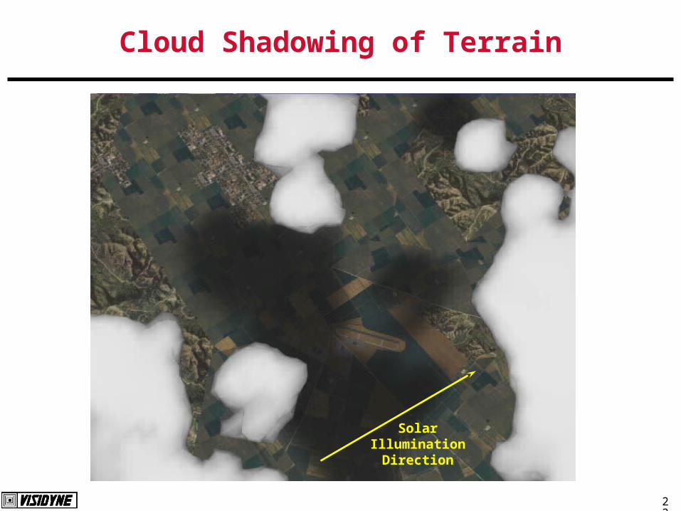
Cloud Shadowing of Terrain
Solar Illumination
Direction

24
Dust Cloud from 105-mm Tank Round Buried in Wet Cohesive Soil
1 second 3 seconds 10 seconds 30 seconds
Time after tank round detonation

25
CloudScape® VR Sample ImageSooty Smoke Plume

26
Vega Mode vs. SensorVision (quantitative) Mode
CloudScape® VR with Vega™
CloudScape® VR with SensorVision™

27
SensorVision (quantitative) Mode
Vega window showing observer’s view of a tank and a large munitions cloud
SAOimage window showing quantitative values from the “grabbed” image

28
Multi-Spectral Rendering
Visible
MWIR3 to 5 microns
LWIR8 to 12 microns
Night Vision

29
CloudScape® VR Iso-Surface VisualizationHazardous Material Plume Example

30
How Does CloudScape® VR Work?
1. Rendering

31
CloudScape® VR Rendering Approach
Rendered Dust CloudCloud FacetizationVertex Radiance and Transmission
Parameterized by Angle
Vertex geometry, radiance and transmission information is contained in OpenCloud database
CloudScape® VR renders cloud in real time
32
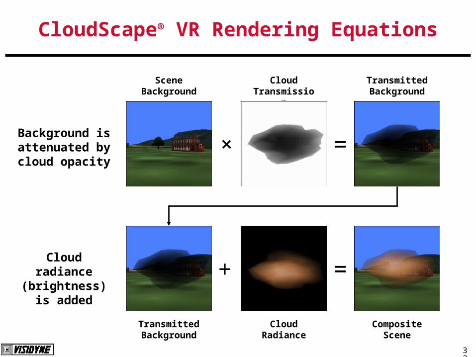
CloudScape® VR Rendering Equations
Cloud Radiance
Composite Scene
Transmitted Background
+ =
Cloud Transmission
Scene Background
+ =
Transmitted Background
Background is attenuated by cloud opacity
Cloud radiance (brightness) is
added

33
CloudScape® VR Rendering Timelines
Facetized cloud model is combined with terrain and other models and rendered at frame rate (typically 30 to 60 Hz).
Cloud radiative properties are interpolated asynchronously for viewer location and aspect from tabulated bi-directional values at each vertex (typically a few Hz).
Cloud facet geometry and vertex radiative properties are obtained from a CloudScape® VR database at “key frame” times (typically every few seconds).
Key-frame rates depend on model; asynchronous and rendered frame rates depend on processor performance.
34
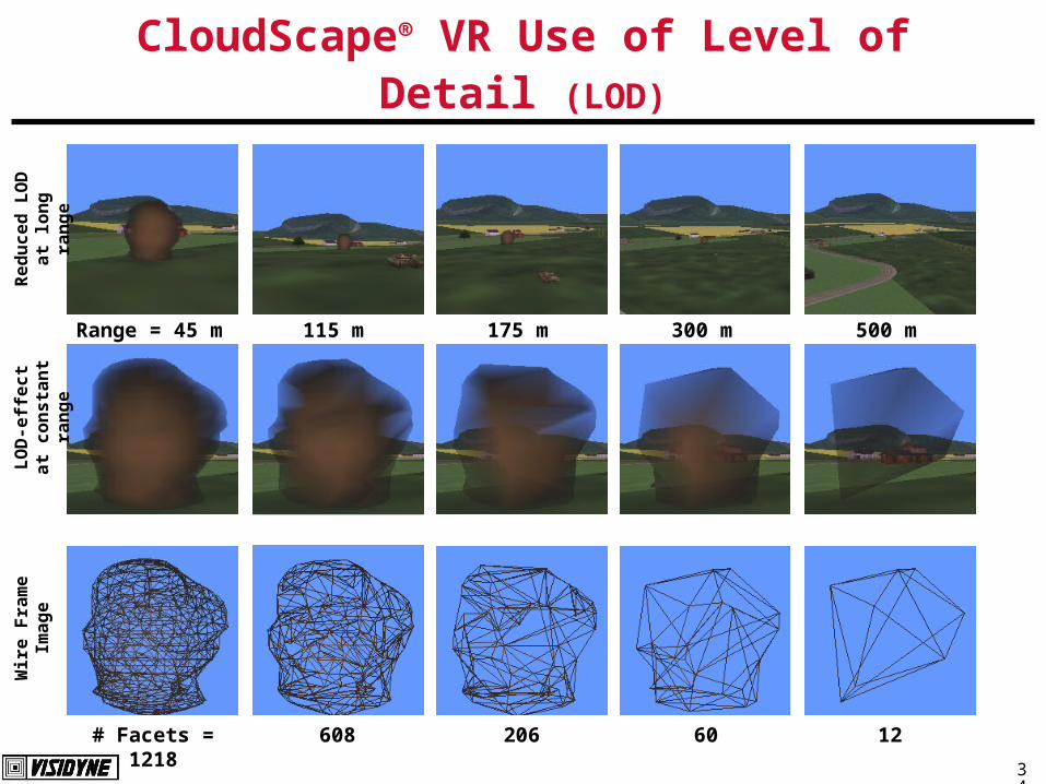
CloudScape® VR Use of Level of Detail (LOD)
Range = 45 m 115 m 175 m 300 m 500 m
# Facets = 1218 608 206 60 12
Re
du
ce
d L
OD
a
t lo
ng
ra
ng
eL
OD
-eff
ec
t a
t c
on
sta
nt
ran
ge
Wir
e F
ram
e
Ima
ge
35
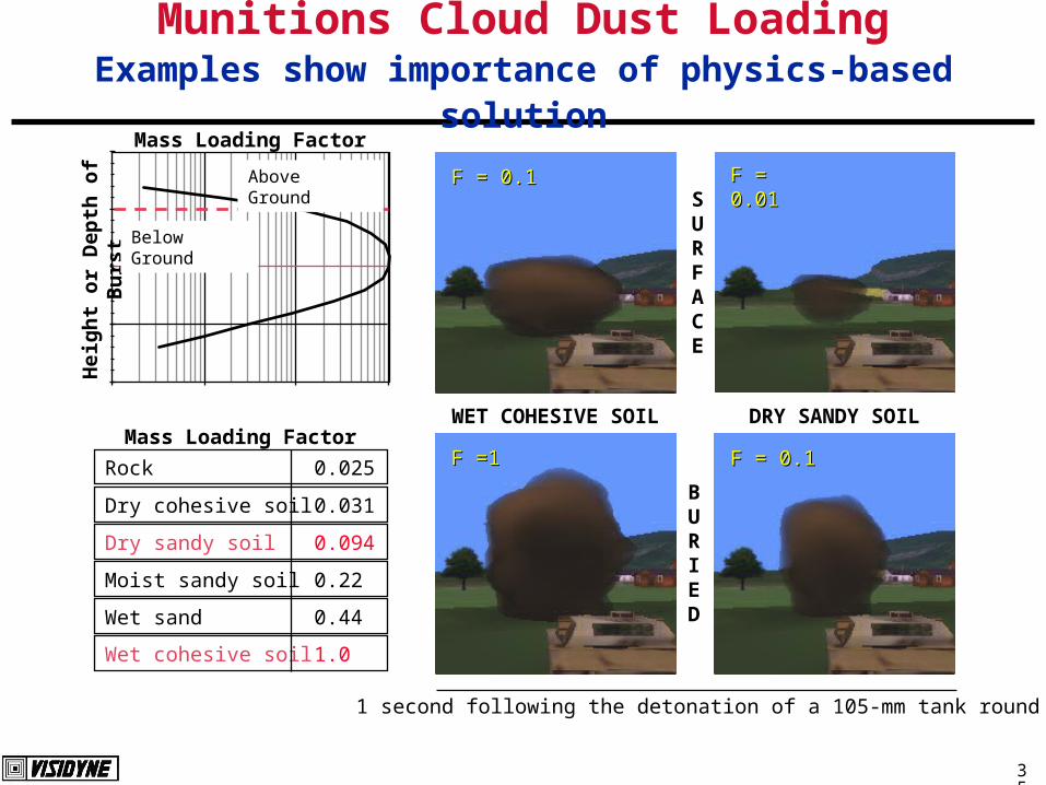
Munitions Cloud Dust LoadingExamples show importance of physics-based solution
Hei
gh
t o
r D
epth
of
Bu
rst
Above Ground
Below Ground
Dry cohesive soil 0.031
Dry sandy soil 0.094
Moist sandy soil 0.22
Wet sand 0.44
Wet cohesive soil 1.0
Rock 0.025
Mass Loading FactorWET COHESIVE SOIL DRY SANDY SOIL
SURFACE
BURIED
Mass Loading Factor
F =1F =1
F = 0.1F = 0.1 F = 0.01F = 0.01
F = 0.1F = 0.1
1 second following the detonation of a 105-mm tank round

36
CloudScape® VR Visualization Steps
CloudGen™
Cloud 3-D Particulate Database
Select a cloud type
CloudRad™Select waveband(s),
solar illumination angle(s) and atmospheric state
OpenCloud™ Radiometric Database
Execute simulation CloudScape® VR
Real-time Cloud Imagery
Pre
pro
cess
ing
Ru
n T
ime

37
How Does CloudScape® VR Work?
2. Databases
38
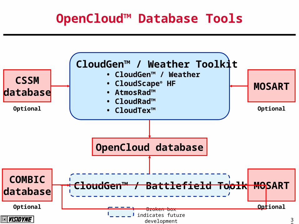
OpenCloud™ Database Tools
CSSMdatabase
COMBICdatabase
CloudGen™ / Weather Toolkit• CloudGen™ / Weather• CloudScape® HF• AtmosRad™• CloudRad™• CloudTex™
OpenCloud database
CloudGen™ / Battlefield Toolkit
Optional
Optional Broken box indicates future development
MOSART
Optional
MOSART
Optional

39
Radiative Processes Modeled in CloudRad®
ReflectedSunshine
TransmittedEarthshine
ThermalEmission
ReflectedEarthshine
EarthshineShadows
CloudAttenuation
Skyshine
Reflected Skyshine
Path Radiance
Path Absorption
Sunshine / Moonshine

40
Cloud Radiance CalculationUsed in CloudRad™
Cloud illumination– Solar (or lunar) radiation
– Sky shine
– Earth shine Can include illumination from city lights
Self-shadowing of cloud– Shadowing of ground by clouds is also recorded
Cloud scattering– Single-particle scattering
– Multiple-particle scattering Build-up factor approximation is used
– Narrow angle forward scattering Thermal emission Obscuration
– Total direct beam loss
– Wide-angle beam loss

41
Details of CloudRad™ Calculation
Conversion of mass density to effective extinction coefficient– Robust , efficient Mie scattering model (developed by Dr. Thompson)
– Variety of particle size distributions
– Complex indices of refraction Water, ice, dust, and smoke Ultraviolet, visible, and infrared
Cloud surface facetization– Marching Cubes algorithm
– Vertex culling for levels of detail Tabulation of bi-directional radiance and transmission at vertices
– Fast, approximation to integral form of radiative transfer equation Exact in single scattering limit Validated multiple scattering approximation Variety of sources: sun, moon, earthshine and skyshine
– MOSART (U.S. Air Force Research Laboratory) parametric databases Atmospheric path attenuation and radiance Up- and down-welling atmospheric diffuse radiation
42
How Does CloudScape® VR Work?
3. Validation

43
San Luis Obispo, CA
Meas 5 x 10-
6 Calc 5 x
10-6
Meas 4 x 10⁻⁶
Calc 5 x 10⁻⁶
Meas 30 x 10-6
Calc 40 x 10-6
Early MorningUniform Stratus LayerSWIR Window Region
Meas 8 x 10⁻⁶
Calc 7 x 10⁻⁶
Data Comparisoncalculated vs. measured cloud radiance (W/cm2/sr)
44
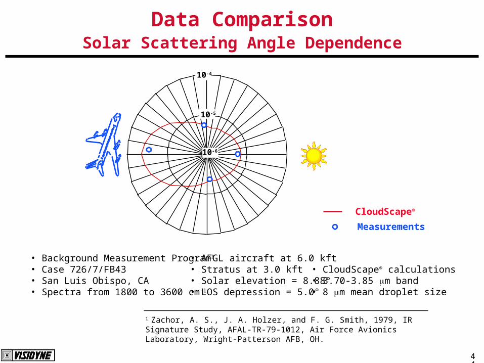
Data ComparisonSolar Scattering Angle Dependence
1 Zachor, A. S., J. A. Holzer, and F. G. Smith, 1979, IR Signature Study, AFAL-TR-79-1012, Air Force Avionics Laboratory, Wright-Patterson AFB, OH.
• AFGL aircraft at 6.0 kft• Stratus at 3.0 kft• Solar elevation = 8.88°• LOS depression = 5.0°
• Background Measurement Program1
• Case 726/7/FB43• San Luis Obispo, CA• Spectra from 1800 to 3600 cm-1
• CloudScape® calculations• 3.70-3.85 m band• 8 m mean droplet size
10-4
10-5
10-6
CloudScape®
Measurements

45
Data ComparisonSpectral Details
Wavelength (m)
Forward (data)
Forward
Backward (data)
Backward
Side (data)
Side
3.25 3.5 3.75 4.00 4.25
10-4
10-6
10-5
10-7In-B
and
Rad
ianc
e (W
/cm
2 /sr
)/(2
5 cm
-1)

46
How Can I Get Cloud Databases?

47
Ways to Obtain OpenCloud™ Databasesfor use with CloudScape® VR
Sample databases are included with CloudScape® VR product Database packages will be available from Visidyne
– Weather Cloud Database
– Battlefield Cloud Database Database generation toolkits will be available from Visidyne
– CloudGen™/Weather Toolkit (release planned for Summer 1999) Beta demonstration version available
– CloudGen™/Battlefield Toolkit (in development) Engineering services available from Visidyne, Inc.
– Custom databases for clouds and atmospheric obscurants
– Customer specified: Sensor bands Cloud types Illumination conditions
OpenCloud™ database format specifications are available upon request

48
CloudGen™/Weather Toolkit
CloudGen™/Weather– Generates 3-D particulate database– Alternatively, CSSM* databases can be used
AtmosRad– Generates optional atmospheric propagation database with MOSART*– Sample databases provided for standard atmospheric states and bands
CloudScape® HF– High-fidelity pixel-by-pixel calculation of cloud radiance and transmission– FITS file output
CloudRad™– Generates OpenCloud radiance database for use in CloudScape® VR
CloudTex™– Generates texture file for use in CloudScape® VR
Sample cases– Input and output files for weather-cloud databases
*Use of MOSART and CSSM are optional; these codes may be obtained directly from U.S. Air Force Research Laboratory (Phillips Site)

49
CloudGen™/Weather ToolkitMain Screen

50
Relationship of Tools and DatabasesCloudScape® VR and CloudGen™/Weather Toolkit
Vega™
CloudRad™
Particulate Database
CloudGen™/Weather
Radiometric DatabaseCloudTex
Texture Database Purchased Databases
Developer Application
SensorVision™
CloudScape® VR
API Library Calls
CSSM
CSSM Database
Atmospheric Database
MOSART
ORMAT™AtmosRad™

51
CloudGen™/Weather
User input
– Number of cloud layers (currently 1)
– For each layer Horizontal extent, resolution and orientation Ceiling, cloud-top altitude, vertical resolution Atmospheric mean vertical profile (sounding data) Percent cover Wind speed and direction Random number seed Cloud type, OR
Particulate type Particle size distribution parameters Structure parameters
Alternatively, a CSSM*-generated database can be used
* Air Force Research Laboratory model

52
* Army Research Laboratory model (distribution restrictions apply)
CloudGen™/Battlefield
User input: generic model mode– Non-buoyant burst
– User input Soil type (6 categories) TNT-equivalent yield of munitions Switch between surface or shallow-buried burst Wind speed and direction (vertical profile)
– Unrestricted distribution COMBIC* model mode
– Reads user-supplied COMBIC-generated cloud databases
– Adds spatial structure and wind effects
53
What are the CloudScape® VR Development Plans?

54
CloudScape® Family Software
CloudGen™ / Weather Toolkit
– Fall 1999
Weather Cloud Database Set
– Fall 1999
CloudGen™ / Battlefield Toolkit and Databases
– Early 2000
CloudScape® VR
– Version 1.1 currently shipping
– Version 1.2 release: fall 1999

55
CloudScape® VR 1.2 Enhancements
Support for CGWT databases with 2-D texture
Cloud Shadows
Tiled-clouds
– (for large spatial extent)
Corrections of coding errors in 1.1
Updated LynX panel
56
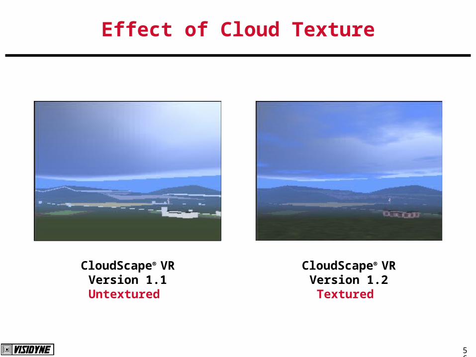
Effect of Cloud Texture
CloudScape® VR Version 1.1Untextured
CloudScape® VR
Version 1.2Textured

57
Effect of Cloud Shadows
Vega simulation without CloudScape® VR
No Clouds
CloudScape® VR Version 1.1
Clouds, no Shadows
CloudScape® VR
Version 1.2Clouds and Shadows

58
Phenomena which can be Supported by OpenCloud Database Format
Candidate Modules for Future CloudGen™ Offerings
Rain: steady-state rainfall consistent with weather cloud model Vehicular: clouds from vehicular land traffic Fire: flame and smoke from steady-state ground fires Exhaust: heated exhaust gas from vehicles Muzzle: flash from guns Plume: from missiles and aircraft Stack: steady-state steam/smoke from ground sources Effluent: transient, non-instantaneous expulsion of material into the atmosphere (e.g.
underground bunker destruction) Obscurant: battlefield smoke Flare: IR battlefield countermeasure Splash: underwater detonations Chaff: clouds of RF reflectors Volcano: dynamic particulate and gaseous high-altitude clouds

59
Where Can I Find Technical References?

60
References
DeVore, J.G., J.H. Thompson, and R.J. Thornburg, 1995, “CloudScape®: Stochastic Cloud Visualization from Volumetric Descriptions:, in Cloud Impacts on DoD Operations and Systems 1995 Conference, D. Grantham, editor, Phillips Laboratory/GPAA, Hanscom AFB, MA, 41-44.
Schlueter, W. A., and J. G. DeVore , 1995, “Radiometric Atmospheric Dust Environments for Distributed Interactive Simulations”, in Proceedings, Sixth Annual Ground Target Modeling and Validation Conference, Volume I, K.R. Johnson, editor, Keweenaw Research Center, Houghton, MI, 19-27.
DeVore, J.G., J.H. Thompson, and R.J. Thornburg, 1996, “Physics-based Background Visualization from Volumetric Cloud Descriptions Using CloudScape®”, Proceedings of the IRIS Specialty Group on Targets, Backgrounds, and Discrimination, Sandia National Laboratory, Albuquerque, NM, 30 January - 1 February.
DeVore, J. G., J. H. Thompson, K. W. Sartor, T. L. Stephens, and R. J. Thornburg, “CloudScape® VR: Radiometric Visualization of Clouds for Interactive Training and Simulation”, Proceedings of the Cloud Impacts on DoD Operations and Systems Conference, PL-TR-97-2112, Phillips Laboratory, Hanscom AFB, MA, 1997.
Thornburg, R. J., J. G. DeVore, J. H. Thompson, R. J. Jordano, and T. L. Stephens, “Validation of CloudScape ® AF”, Proceedings of the Cloud Impacts on DoD Operations and Systems Conference , PL-TR-97-2112, Phillips Laboratory, Hanscom AFB, MA, 1997.
The references listed above are available in Adobe’s PDF format by anonymous ftp to the cloud/papers directory at ftp.visidyne.com.

61
Additional Information
Technical Contact
– Dr. John G. DeVoreVisidyne, Inc.5951 Encina Road #208 Goleta, CA 93117-2211805-683-4277 (voice) 805-683-5377 (fax)e-mail: [email protected]
Marketing Contact
– Ms. Kristin DavisMultiGen-Paradigm, Inc.14900 Landmark Blvd. #400Dallas, TX 75240972-960-2301 (voice) 972-960-2303 (fax)e-mail: [email protected]
Web Sites
– Visidyne: www.visidyne.com
– MultiGen-Paradigm: www.multigen.com