CLOUD INFRASTRUCTURE NETWORK AND SECURITY USER · PDF filecloud infrastructure network and...
49
CLOUD INFRASTRUCTURE NETWORK AND SECURITY USER GUIDE FOR VIRTUAL SERVER (DEDICATED) GEN2
Transcript of CLOUD INFRASTRUCTURE NETWORK AND SECURITY USER · PDF filecloud infrastructure network and...

CLOUD INFRASTRUCTURE NETWORK AND SECURITY USER GUIDE FOR VIRTUAL SERVER (DEDICATED) GEN2
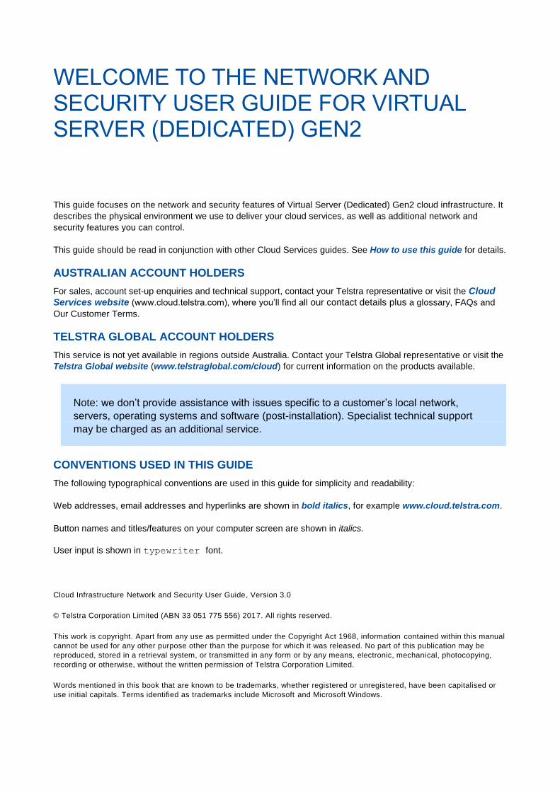
WELCOME TO THE NETWORK AND SECURITY USER GUIDE FOR VIRTUAL SERVER (DEDICATED) GEN2
This guide focuses on the network and security features of Virtual Server (Dedicated) Gen2 cloud infrastructure. It
describes the physical environment we use to deliver your cloud services, as well as additional network and
security features you can control.
This guide should be read in conjunction with other Cloud Services guides. See How to use this guide for details.
AUSTRALIAN ACCOUNT HOLDERS
For sales, account set-up enquiries and technical support, contact your Telstra representative or visit the Cloud
Services website (www.cloud.telstra.com), where you’ll find all our contact details plus a glossary, FAQs and
Our Customer Terms.
TELSTRA GLOBAL ACCOUNT HOLDERS
This service is not yet available in regions outside Australia. Contact your Telstra Global representative or visit the
Telstra Global website (www.telstraglobal.com/cloud) for current information on the products available.
Note: we don’t provide assistance with issues specific to a customer’s local network,
servers, operating systems and software (post-installation). Specialist technical support
may be charged as an additional service.
CONVENTIONS USED IN THIS GUIDE
The following typographical conventions are used in this guide for simplicity and readability:
Web addresses, email addresses and hyperlinks are shown in bold italics, for example www.cloud.telstra.com.
Button names and titles/features on your computer screen are shown in italics.
User input is shown in typewriter font.
Cloud Infrastructure Network and Security User Guide, Version 3.0
© Telstra Corporation Limited (ABN 33 051 775 556) 2017. All rights reserved.
This work is copyright. Apart from any use as permitted under the Copyright Act 1968, information contained within this manual
cannot be used for any other purpose other than the purpose for which it was released. No part of this publication may be
reproduced, stored in a retrieval system, or transmitted in any form or by any means, electronic, mechanical, photocopying,
recording or otherwise, without the written permission of Telstra Corporation Limited.
Words mentioned in this book that are known to be trademarks, whether registered or unregistered, have been capitalised or
use initial capitals. Terms identified as trademarks include Microsoft and Microsoft Windows.

WHAT’S INSIDE
CHAPTER 1 HOW TO USE THIS GUIDE 4
CHAPTER 2 OUR DATA CENTRES 5
CHAPTER 3 HOW WE DELIVER CLOUD SERVICES 7
CHAPTER 4 YOUR VIRTUAL DATA CENTRES 10
CHAPTER 5 VIRTUAL SERVER NETWORKS AND SECURITY 12
CHAPTER 6 YOUR PUBLIC NETWORK 16
CHAPTER 7 YOUR PRIVATE NETWORK 20
CHAPTER 8 TELSTRA’S CLOUD GATEWAY 26
CHAPTER 9 TELSTRA NEXT IP® NETWORK 27
CHAPTER 10 IPSEC VPN 28
CHAPTER 11 DUAL NETWORK CONNECTION 31
CHAPTER 12 STATIC ROUTES 32
CHAPTER 13 FIREWALLS 34
CHAPTER 14 LOAD BALANCERS 40
CHAPTER 15 MANAGEMENT CONNECTION 44
CHAPTER 16 SMTP MAIL RELAY 46
CHAPTER 17 APPENDIX A: ROUTING PRIVATE TRAFFIC WITHIN YOUR VIRTUAL HOST 48

CHAPTER 1 HOW TO USE THIS GUIDE 4
CHAPTER 1 HOW TO USE THIS GUIDE
The network and security environment referred to in this document is specific to the Virtual Server (Dedicated)
Gen2 service. You can use this guide as a supplement to the Virtual Server (Dedicated) Gen2 User Guide
This guide includes instructions on how to create and modify virtual server network connections and security
features. The guide assumes you have access to the Cloud Services management console – for more information
about using the Cloud Services management console, see the virtual server user guide listed above.
For details about managing your account and accessing the Cloud Services management console, see the
Account Management Guide.
Our Cloud Services diagram below shows what’s covered in this guide, and where to go for further details.

CHAPTER 2 OUR DATA CENTRES 5
CHAPTER 2 OUR DATA CENTRES
Our data centres securely house the physical resources and infrastructure used to provide our cloud solutions. We
own, operate and maintain all our physical data centres. Data centres are currently located in:
Melbourne
Perth
Sydney
The physical infrastructure within our data centres is protected by four layers of security:
Outer perimeter
Site grounds
Buildings (including electronically-secured floors and CCTV corridor surveillance)
Internal rooms (including CCTV surveillance for rooms hosting ICT infrastructure and locked cabinets and
cages)
Data centres provide you with connectivity to:
The internet
Your private networks via a Cloud Gateway network (Melbourne and Sydney data centres only), Telstra Next
IP network (Perth) or IPsec VPN tunnel
Your stored data
Your dedicated infrastructure resources
You can select which data centre(s) you will use to source cloud infrastructure services. We describe your chosen
source as your virtual data centre. You’ll find instructions for managing your virtual data centres later in this
guide.
Our backup services use separate data centres for short-term storage and long-term retention.
AVAILABILITY AND RELIABILITY
Our data centre infrastructure is fully redundant to protect your services and data from a single point-of-failure.
This enables us to provide cloud services with high levels of availability, service support and coverage.
Infrastructure is continuously monitored by our Cloud Services support team using advanced monitoring tools and
denial of service protection.
Network reliability is maintained by redundancy on two levels:
Intra-component redundancy - including dual supervisor engines, multiple power supplies served by diverse
power sources and fan redundancy
Inter-component redundancy - including dual physical components and multiple links
Service level agreements can be viewed in Our Customer Terms (Australian customers only) or your separate
agreement with us.

CHAPTER 2 OUR DATA CENTRES 6
NETWORK SECURITY
All our data centres are located in or close to capital cities, and housed in high security physical environments.
Your data is protected 24/7 by our team of security specialists. The role of our Cloud Services support team is to
provide:
Protection of the physical infrastructure that provides your cloud services
Privacy and security of individual customer’s data in a multi-tenancy environment
Basic security controls at the infrastructure and network level
Infrastructure logging, alerting and auditing
Some of the security features of our cloud services infrastructure include:
Network-based firewalls
Remote access security
Regular vulnerability checks
Denial of service protection
Privacy controls
Our cloud infrastructure is protected by a sophisticated intrusion detection and prevention system (IDS/IDP) and a
firewall protecting the entire cloud infrastructure perimeter.
To maintain security standards, we use leading technologies to perform regular network and infrastructure security
updates. We also perform regular penetration testing of our platform using a third party.
In addition to the security measures our infrastructure provides, we offer ways for you to customise and enhance
your own cloud network security.
CUSTOMER ISOLATION
Your data and virtual resources are separated from other customers on three layers – network, compute and data.
Network isolation is achieved using technology that ensures low-level network separation, and uses advanced and
encrypted communication channels (e.g. SSL VPN). Transit networks between customers’ virtual servers and data
storage areas are isolated and unreachable from any network.
Compute isolation is separation that occurs at the physical hardware level within our data centres.
Data isolation dedicates entire volumes to a single customer.
CHAPTER 3 HOW WE DELIVER CLOUD SERVICES 7
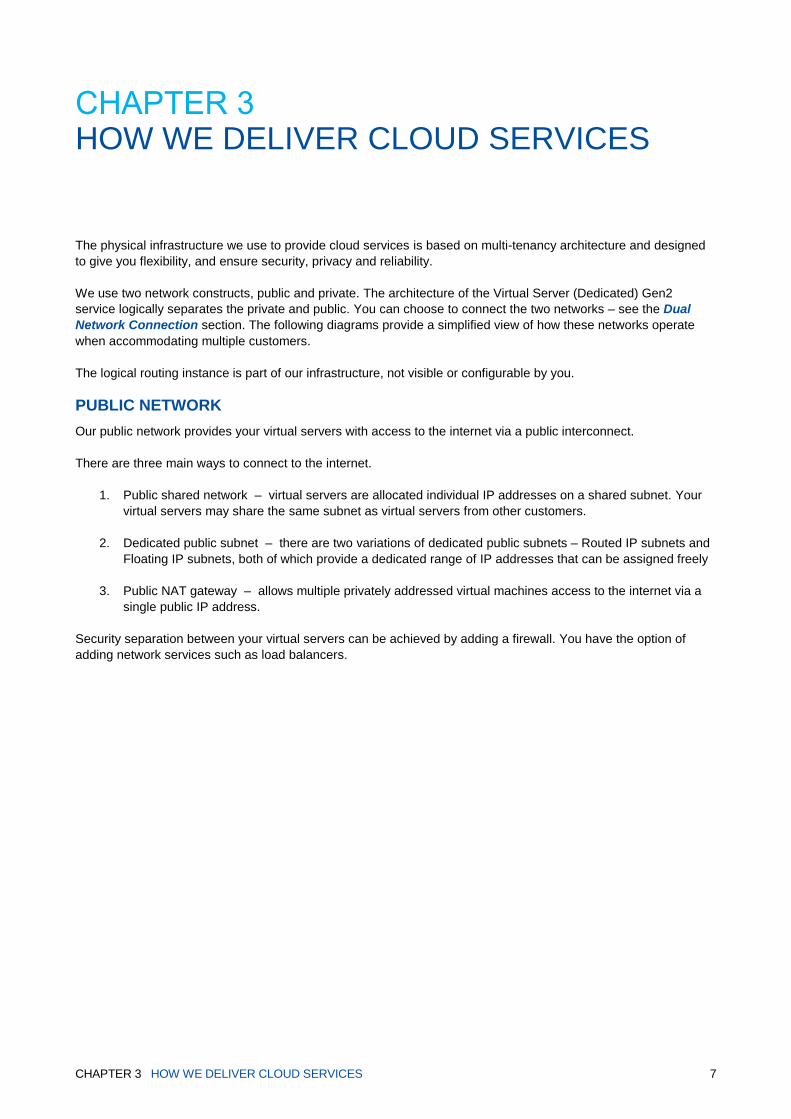
CHAPTER 3 HOW WE DELIVER CLOUD SERVICES
The physical infrastructure we use to provide cloud services is based on multi-tenancy architecture and designed
to give you flexibility, and ensure security, privacy and reliability.
We use two network constructs, public and private. The architecture of the Virtual Server (Dedicated) Gen2
service logically separates the private and public. You can choose to connect the two networks – see the Dual
Network Connection section. The following diagrams provide a simplified view of how these networks operate
when accommodating multiple customers.
The logical routing instance is part of our infrastructure, not visible or configurable by you.
PUBLIC NETWORK
Our public network provides your virtual servers with access to the internet via a public interconnect.
There are three main ways to connect to the internet.
1. Public shared network – virtual servers are allocated individual IP addresses on a shared subnet. Your
virtual servers may share the same subnet as virtual servers from other customers.
2. Dedicated public subnet – there are two variations of dedicated public subnets – Routed IP subnets and
Floating IP subnets, both of which provide a dedicated range of IP addresses that can be assigned freely
3. Public NAT gateway – allows multiple privately addressed virtual machines access to the internet via a
single public IP address.
Security separation between your virtual servers can be achieved by adding a firewall. You have the option of
adding network services such as load balancers.

CHAPTER 3 HOW WE DELIVER CLOUD SERVICES 8
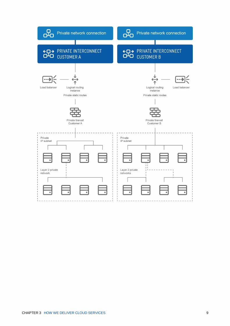
PRIVATE NETWORK
The private network provides your own logical routing instance to which you can add private IP subnets completely
separate to your public network. If required, our private network allows you to access virtual servers in your private
network, via a private interconnect, through a private network connection.
Security separation between your virtual servers is achieved with the firewall provided. You have the option of
adding network services such as load balancers.
Private layer 2 networks allow non-routed private networks to create tiered network architectures with freedom to
allocate any IP address you require.
CHAPTER 3 HOW WE DELIVER CLOUD SERVICES 9

CHAPTER 4 YOUR VIRTUAL DATA CENTRES 10
CHAPTER 4 YOUR VIRTUAL DATA CENTRES
A virtual data centre represents the collection of cloud resources you’re drawing from a specific physical location.
A single virtual data centre also represents a logically-isolated network within your cloud solution. Each of your
virtual data centres can be viewed as a network configuration diagram, in the Network & security page of the
management console.
MULTIPLE VIRTUAL DATA CENTRES
Cloud infrastructure lets you draw your cloud resources from multiple data centres in different locations and assign
resources to your choice of virtual data centre.
You can create multiple virtual data centres drawing resources from the same physical data centre location. If you
choose to do this, each virtual data centre will form a logically-isolated network with its own private interconnect.
By default these virtual data centres will have no communication between each other. Separate load balancers
and network connections will be required for each virtual data centre. Firewalls will be added by default per virtual
data centre.
ADD A VIRTUAL DATA CENTRE
You can add a new virtual data centre at any time by purchasing a new compute service.
RENAME A VIRTUAL DATA CENTRE
You can customise the name of a virtual data centre to make the name more meaningful to your operations.

CHAPTER 4 YOUR VIRTUAL DATA CENTRES 11
REMOVE A VIRTUAL DATA CENTRE
A virtual data centre will be removed after you remove all the compute services it contains.
NOMINATE A DATA CENTRE
If your cloud solution is contained within a single virtual data centre, then your resources will be automatically
assigned to that virtual data centre.
But if you’re operating your cloud solution across multiple data centre locations, you’ll be asked where you want to
assign certain cloud resources as you add them, such as:
SSL VPN users
SMTP mail relay
Other types of resources can only be created from within a specific virtual data centre environment.
Firewalls
Load balancers
Private network connections
Dedicated subnets
Static Routes
Each of your virtual data centres can be viewed in the Cloud Services management console as a network diagram.
These diagrams provide an alternative way of adding virtual servers, resources, and network connections to your
existing configuration. Select the item on the diagram you want to configure, and the fields required to add the item
will appear on screen.

CHAPTER 5 VIRTUAL SERVER NETWORKS AND SECURITY 12
CHAPTER 5 VIRTUAL SERVER NETWORKS AND SECURITY
You can choose to connect a virtual server within your data centre to a public or private network, or use dual
homing to connect a virtual server to both networks.
Each of your networks can contain virtual servers and associated firewalls and load balancers. All virtual servers
within a network can be allowed to communicate with each other, or separated using firewall rules.

CHAPTER 5 VIRTUAL SERVER NETWORKS AND SECURITY 13
CLOUD INFRASTRUCTURE NETWORK FEATURES
There are a number of features you can customise to manage traffic flow, privacy and security of your data. Apart
from internet access, all network features are optional and inactive by default.
Many of these features are described in detail, later in this guide.
To view pricing of optional network features, refer to the pricing guide for your data centre location.
Dual homing allows a single server to be accessed via both public and private network connections, and
communicate with virtual servers in both your public and private networks.
SSL VPN connection is a way to remotely and securely access your vCenter server and virtual servers on private
networks.
Firewalls are included as part of your service. They can be configured by you to allow or deny traffic through
groups or individual virtual servers. A separate firewall exists for each network, and each compute service within
your cloud solution.
Load balancers can be used to distribute traffic across multiple virtual servers within the same network.
Security add-ons are optional features available to enhance your network security.
SMTP mail relay is an optional service allowing you to send outbound email from a virtual server in the cloud.
Static Routes are pre-determined paths you manually choose to determine where network information must
follow to reach a specific host or network. They are available on your private and public networks.
NAT Gateway is an optional feature allowing multiple virtual services to acess the internet via a single public IP
address.
Dedicated public networks are available as either Routed or Floating networks allowing more complex public
facing infrastructure.
Layer 2 private networks make it possible to build tiered network constructs were routing between subnets can
be controlled by appliances or virtual servers.

CHAPTER 5 VIRTUAL SERVER NETWORKS AND SECURITY 14
NETWORK SECURITY ADD-ONS
These optional network security add-ons can be added to your cloud solution at any time, to maximise the security
of your cloud resources and data.
For more information including pricing, see the Pricing Guide for your virtual data centre location.
INTERNET PROTECTION
Internet Protection Mail helps keep spam, viruses and inappropriate content off your network. You can choose to
have anti-virus and anti-spam filtering software applied to virtual servers connected to the internet and hosted mail
servers. The software scans incoming emails to detect spam and viruses.
Internet Protection Web helps shield your business from known and emerging viruses and web threats including
malware and spyware. Web filtering can be applied to virtual servers in your public network and hosted proxy
servers.
VULNERABILITY DISCOVERY
Vulnerability discovery scans virtual servers in your public networks to identify and prioritise potential weak points
and security exposures. The report produced during the scan details and assigns criticality ratings to any exposure
detected per-server.
DENIAL OF SERVICE (DOS) PLATFORM PROTECTION
Our Cloud Services platform is shared and as such a DoS attack on one customer could affect the platform and
performance of other customers if left unmanaged. As a standard feature, Telstra’s Security Operations Centre
monitors the platform internet traffic. If unusual traffic is detected we automatically rate limit the traffic to ensure
continued performance of other customers. We’ll notify you if your virtual servers are attacked and your internet
connection has been rate limited.
We’ll keep you informed by:
Emailing you to inform you of the attack, and potential reduction in your service performance
Emailing you when the attack has passed, and normal service performance can resume
DoS platform protection is included with your cloud services and requires no activation on your part. This level of
protection is provided in all virtual data centre locations. You can’t remove or configure this standard level of
protection, however if using any of our Australian virtual data centre locations, you have the option of purchasing
our DoS protection service.
DENIAL OF SERVICE PROTECTION
Denial of service protection is an optional premium service to prevent malicious attacks across your cloud solution.
In the event of an attack traffic is diverted to Telstra’s Security Operations Centre where it is cleaned before being
routed back to your virtual data centre.
More information about this service is available on the Telstra website.
GATEWAY PROTECTION ADVANCED (GPA)
The Gateway Protection Advanced (GPA) service secures your multi-cloud, internet and Next IP services against
malicious attacks, inappropriate usage, and unauthorised access with managed cloud-enabled next-generation
security appliances.
The service offers a platform-specific gateway for complex connectivity and cloud security requirements with ability
to scale up for performance and reliability.
Contact your Telstra representative for more information.
CHAPTER 5 VIRTUAL SERVER NETWORKS AND SECURITY 15
NETWORK CONFIGURATION
A wide range of network configurations are made possible using combinations of:
Firewalls
Routing
Load balancers
Private IP subnets
Public IP addressing
Network connections
Virtual data centres
Virtual server networks can be configured in multiple tiers and zones.
Refer to the Infrastructure Design Guide to see examples of how common network scenarios can be built using
our cloud solution.

CHAPTER 6 YOUR PUBLIC NETWORK 16
CHAPTER 6 YOUR PUBLIC NETWORK
VIRTUAL SERVERS
Virtual servers can be connected to the internet via multiple public network options. The default option provided is
the public shared network for individual virtual servers. You can choose to move them between the public shared,
public dedicated and NAT gateway options.
FIREWALLS
A firewall is installed by default in your Virtual Server (Dedicated) Gen2 environment to maintain security from the
outset. See the firewalls section of this guide for further information. Each compute service comes with a
dedicated firewall for public network, which is configured separately to the private network firewall.
IP ADDRESSING
We allocate public IP addresses to virtual servers in your public network. Depending on the public networking
options chosen, IP addresses are either allocated individually to virtual servers or as blocks of IP addresses in the
cases of dedicated public subnets.

CHAPTER 6 YOUR PUBLIC NETWORK 17
Your options are:
Shared public network
Dedicated public subnets
Public NAT gateway
Shared public network
You can allocate up to five individual IP addresses to your virtual servers in the public network. These IP
addresses may not be sequential. All public IP addresses allocated to virtual servers are static.
Once provided, you can’t move your IP addresses to another server. IP addresses should not be manually
changed after the initial configuration. Modifying the IP addresses assigned to a virtual server’s internet vNIC could
lead to a loss of connection to your public interconnect and internet.
Multiple IP address can be requested and allocated to the same vNIC.
Dedicated public subnets
There are two types of dedicated public subnets, which give you the freedom to assign IP addresses as required.
1. Routed IP subnets – allows you to have a range of dedicated IP addresses directly accessible to and from
the internet.
2. Floating IP subnets – allows you to place a virtual appliance between the internet and your virtual
machines. You’ll get access to a dedicated range of IP addresses not connected directly to the internet.
Static Routes will need to be used to direct the floating IP range to your virtual appliance. You must have
a Routed IP subnet before you can request a Floating IP subnet.
Public NAT gateway
A NAT Gateway provides the ability for multiple private network address spaces to masquerade as a single Public IP address, allowing direct internet access without the need to consume a Public IP Address per server (Source NAT). Up to three privately addressed subnets can be added behind the NAT gateway allowing any virtual server access to internet services with only outgoing connections
It also allows a single internal Private IP Address to be reached from Internet (Destination NAT). An additional
public IP is added to the NAT gateway and pointed at one of your attached privately addressed subnets, allowing
incoming internet traffic. Outgoing traffic from that private IP will masquerade as the Destination NAT IP address.
Up to five Destination NAT IP addresses can be added to your NAT gateway.
The privately addressed networks that are attached to the NAT gateway are still separate from the Private IP
subnet networks created in your private networking section of the Cloud Services management console. You can
connect the private and public networks as required.
Contact your Telstra Representative for instructions in using these features.
NETWORK RESOURCES
All of our cloud infrastructure network features are available for use within your public network.
LOAD BALANCING
A single load balancer can distribute traffic across multiple virtual servers in any combination of server type, within
your public network. We provide a public IP address for the load balancer. The load balancers section of this
guide contains further information.

CHAPTER 6 YOUR PUBLIC NETWORK 18
MAKING CHANGES TO YOUR PUBLIC NETWORK CONFIGURATION
In general, any changes, additions or removal of network resources can be made by completing a brief online
request form through the Cloud Services management console. There are various forms available to deal with
specific types of request.
After you fill out and submit a form, we’ll get to work processing your request. Each request form states the time it
takes for us to make the particular addition or changes to your service.
We may get in contact with you if we need more information to process your service request, or if some of the
information you provided in the form is incorrect. We’ll contact you using the details stored in your Telstra account,
unless you provided us with an alternative contact when you submitted the request.
You can track a service request in the activity log, accessed from the Cloud Services management console’s
reports section.
The following network and security features can be deployed and customised through the Cloud Services
management console. The Network & security management section is located under Infrastructure in the Cloud
Services management console. From here, you can:
View your shared public IP addresses
Request additional shared public IP addresses
Request dedicated public subnets
View dedicated public subnets
Remove dedicated public subnets
VIEW SHARED PUBLIC IP ADDRESSES You can view your Shared Public IP Addresses through the Network & security section in the Cloud Services
management console.
REQUEST SHARED PUBLIC IP ADDRESSES
You can request a Shared Public IP Address on the Public Shared network via Network & security section in the
Cloud Services management console. The virtual server name and MAC address of the interface must be
supplied. These are used to bind the IP address to the virtual server.
REQUEST DEDICATED PUBLIC SUBNETS
You can order a total of three Dedicated Public Subnets (Routed and Floating) per compute subscription. For
example, you can have one Routed IP Subnet and two Floating IP Subnets.
These are requested by clicking on the Add subnet button in the Network & security section on the Cloud Services
management console and selecting the size of the subnet that you require.

CHAPTER 6 YOUR PUBLIC NETWORK 19
Add subnet button on CSMC
Add subnet panel
A minimum number of blades is required to request a subnet:
• /29 or /28 subnet requires a minimum of 2 blades across all the clusters in your compute
subscription (2 blade minimum is by default anyway)
• /27 subnet requires a minimum of 4 blades across all the clusters in your compute subscription
• /26 subnet requires a minimum of 5 blades across all the clusters in your compute subscription
VIEW DEDICATED PUBLIC SUBNETS You can view your Dedicated Public Subnets through the Network & security section in the Cloud Services
management console.
REMOVE DEDICATED PUBLIC SUBNETS
You can request removal of any of your Dedicated Public Subnets once they’re active. Simply select the Remove
link next to the subnet. The IP addresses used for that subnet will be released. You won’t be able to request the
same IP address again.
Additionally, you can’t remove your final remaining Routed IP Subnet without removing your Floating IP Subnets.
CHAPTER 7 YOUR PRIVATE NETWORK 20
CHAPTER 7 YOUR PRIVATE NETWORK
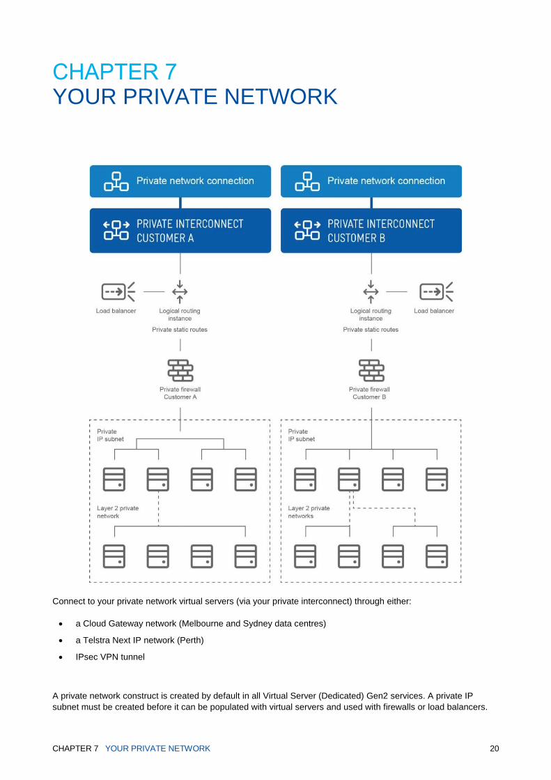
Connect to your private network virtual servers (via your private interconnect) through either:
a Cloud Gateway network (Melbourne and Sydney data centres)
a Telstra Next IP network (Perth)
IPsec VPN tunnel
A private network construct is created by default in all Virtual Server (Dedicated) Gen2 services. A private IP
subnet must be created before it can be populated with virtual servers and used with firewalls or load balancers.
CHAPTER 7 YOUR PRIVATE NETWORK 21
Private IP subnets are nominated by you. Once created, you can allocate private addresses to any of your virtual
servers connected to your subnet. All private IP addresses allocated to virtual servers are static.
In addition to the network security add-ons that can be added to your cloud solution, there are also a number of
network resources you can add to your network at any time.
The following network and security features can be deployed and customised through the Cloud Services
management console. The Network & security management section is located under Infrastructure in the Cloud
Services management console. From here, you can:
Create a private IP subnet
View you private IP subnet
Remove a private IP subnet
Modify your private IP subnet network
Connect to your private network through a Cloud Gateway network
Connect to your private network through a Telstra Next IP network
Connect to your private network through an IPsec VPN tunnel
Create a layer 2 network
View your layer 2 network
Remove a layer 2 network
Add and configure firewalls
Add and configure Static Routes
Add and configure load balancers
Assign SSL VPN users
Set up a SMTP mail relay
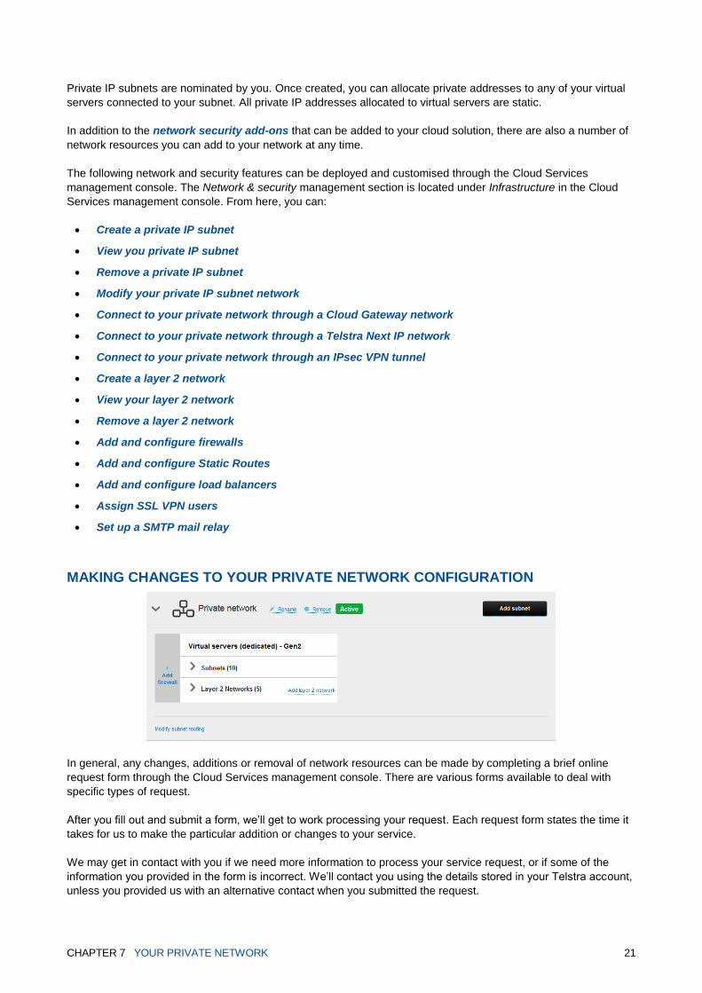
MAKING CHANGES TO YOUR PRIVATE NETWORK CONFIGURATION
In general, any changes, additions or removal of network resources can be made by completing a brief online
request form through the Cloud Services management console. There are various forms available to deal with
specific types of request.
After you fill out and submit a form, we’ll get to work processing your request. Each request form states the time it
takes for us to make the particular addition or changes to your service.
We may get in contact with you if we need more information to process your service request, or if some of the
information you provided in the form is incorrect. We’ll contact you using the details stored in your Telstra account,
unless you provided us with an alternative contact when you submitted the request.

CHAPTER 7 YOUR PRIVATE NETWORK 22
You can track a service request in the activity log, accessed from the Cloud Services management console’s
reports section.
You can separate and distinguish groups of virtual servers within a private network by using private IP subnets.
PRIVATE IP SUBNETS
A private IP subnet enables you to connect to your virtual servers within a private network, and access our cloud
infrastructure via your private interconnect. You’ll need to provide a private IP subnet for each compute service.
The subnets you assign to different virtual server types within the same private network can’t overlap.
You can choose private IP subnets (non-internet addressable) for virtual server groups in your private network.
We currently only support IPv4 addresses. The IP subnet must come from the following RFC 1918 address
ranges:
10.0.0.0 – 10.255.255.255
172.16.0.0 – 172.31.255.255
192.168.0.0 – 192.168.255.255
We reserve the first useable IP address of each subnet. The table below highlights the IP address capacity of
various subnet masks:
IP SUBNETS AVAILABLE IP ADDRESSES
/23 255.255.254.0 509
/24 255.255.255.0 253
/25 255.255.255.128 125
/26 255.255.255.192 61
/27 255.255.255.224 29
/28 255.255.255.240 13
CHAPTER 7 YOUR PRIVATE NETWORK 23
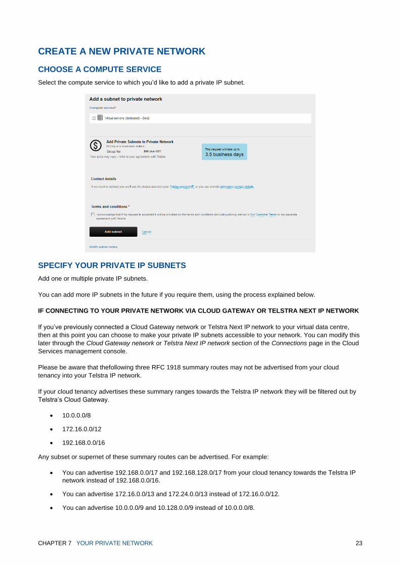
CREATE A NEW PRIVATE NETWORK
CHOOSE A COMPUTE SERVICE
Select the compute service to which you’d like to add a private IP subnet.
SPECIFY YOUR PRIVATE IP SUBNETS
Add one or multiple private IP subnets.
You can add more IP subnets in the future if you require them, using the process explained below.
IF CONNECTING TO YOUR PRIVATE NETWORK VIA CLOUD GATEWAY OR TELSTRA NEXT IP NETWORK
If you’ve previously connected a Cloud Gateway network or Telstra Next IP network to your virtual data centre,
then at this point you can choose to make your private IP subnets accessible to your network. You can modify this
later through the Cloud Gateway network or Telstra Next IP network section of the Connections page in the Cloud
Services management console.
Please be aware that thefollowing three RFC 1918 summary routes may not be advertised from your cloud
tenancy into your Telstra IP network.
If your cloud tenancy advertises these summary ranges towards the Telstra IP network they will be filtered out by
Telstra’s Cloud Gateway.
10.0.0.0/8
172.16.0.0/12
192.168.0.0/16
Any subset or supernet of these summary routes can be advertised. For example:
You can advertise 192.168.0.0/17 and 192.168.128.0/17 from your cloud tenancy towards the Telstra IP
network instead of 192.168.0.0/16.
You can advertise 172.16.0.0/13 and 172.24.0.0/13 instead of 172.16.0.0/12.
You can advertise 10.0.0.0/9 and 10.128.0.0/9 instead of 10.0.0.0/8.

CHAPTER 7 YOUR PRIVATE NETWORK 24
More information about this can be found in the Cloud Gateway Technical Guide:
https://cloud.telstra.com/res/pdf/cloud-gateway-technical-guide.pdf
ALLOCATING IP ADDRESSES TO VIRTUAL SERVERS IN YOUR PRIVATE NETWORK
Individual IP addresses need to be allocated to every virtual server in your private network. You can allocate IP
addresses when you create or dual home a virtual server.
Virtual server IP addresses must fall within a private IP subnet range configured in the private network. We reserve
the first useable IP address of each subnet to configure the gateway of your network.

CHAPTER 7 YOUR PRIVATE NETWORK 25
MANAGE YOUR PRIVATE NETWORK
There are a number of ways to modify and manage your private network, after it’s initially created.
VIEW PRIVATE IP SUBNETS You can view the private IP subnets you’ve created through the Network & security section in the Cloud Services
management console.
ADD IP SUBNETS TO AN EXISTING PRIVATE NETWORK
To add a private IP subnet, see the previous instructions in the Create a private network section.
Creating additional private IP subnets and configuring firewall rules around them, is a way to group and separate
virtual servers within your private network. For examples of how you might do this, see the Infrastructure Design
Guide.
To access virtual servers connected to a private IP subnet via an IPsec VPN tunnel, the IP subnet will need to be
specified as one of your destination subnets when configuring an IPsec VPN tunnel.
Private networks that have been configured to be accessible from the Cloud Gateway network or Telstra Next IP
network will also be reachable from a SSL VPN connection.
To add a new IP subnet, provide both the IP subnet and the IP range within that subnet. See the previous Create
a private network section for detailed instructions.
ADD LAYER 2 PRIVATE NETWORKS TO AN EXISTING PRIVATE NETWORK
Layer 2 Private Networks are non-routed private subnets. They can be requested from the Cloud Services
management console and used to create tiers of networking. As they are not routed, you can use your own IP
addressing on the Layer 2 private network. They would commonly be used with dual-homed virtual servers or to
access appliances.
REMOVE A PRIVATE NETWORK
Before you can remove a private IP subnet or a Layer 2 Private Network, you’ll need to remove any virtual servers
that were connected to this subnet when the server was first created.
Select the Remove subnet or Remove layer 2 private network link.

CHAPTER 8 TELSTRA’S CLOUD GATEWAY 26
CHAPTER 8 TELSTRA’S CLOUD GATEWAY
Telstra’s Cloud Gateway™ is a simple way to access your chosen cloud platforms. It allows you to log in to a
single console, where you can view and manage all of your cloud connections in one place.
Having all of your connections in one place makes it easier to understand the relationships between your Telstra
private networks and your cloud services.
Whether you’re connecting to one or multiple cloud platforms – or adopting a hybrid cloud strategy – Cloud
Gateway offers a simple, one-stop solution that you can scale as your workloads change and your business grows
Cloud Gateway supports Virtual Server (Dedicated) Gen2 and is our only private network in Melbourne and
Sydney. Data centres in other states (Perth) will remain on the Telstra Next IP network until the new service is
available.
Note that you must register for the Cloud Services Store, if you haven’t already done so, in order to purchase
Cloud Gateway. See the Cloud Gateway User Guide for details on how to register, connect and disconnect your
cloud service to the Cloud Gateway network.
CONNECT TO THE CLOUD GATEWAY NETWORK
You can connect to the Cloud Gateway network using the Connections page in the Cloud Services management
console.
You may have to register for the Cloud Services Store, if you haven’t already done so, in order to purchase
Cloud Gateway. This will give you access to the Cloud Gateway management console where you can complete
your connection.
See the Cloud Gateway User Guide for more details on how to connect to the Cloud Gateway network using the
Cloud Gateway management console.
DISCONNECT FROM YOUR TELSTRA NEXT IP NETWORK
You can disconnect your cloud service from Telstra Next IP via the Cloud Gateway management console.
See the Cloud Gateway User Guide for more details on how to disconnect from the Cloud Gateway network
using the Cloud Gateway management console.

CHAPTER 9 TELSTRA NEXT IP® NETWORK 27
CHAPTER 9 TELSTRA NEXT IP® NETWORK
A Telstra Next IP network connection provides a permanent and secure way to connect your local area networks
to your cloud solution (via your private interconnect).
You can use your existing IP MAN, Connect IPor Business IP to access virtual servers in your private networks.
A separate Telstra Next IP network connection is required for each virtual data centre you wish to privately
communicate with. Multiple private network connections will allow communication between private interconnects in
multiple virtual data centres. Multiple virtual data centres can communicate with one another when each one is
connected to the same Telstra Next IP network.
A Telstra network connection can only be provided to your office locations within Australia.
Note: all Telstra Next IP network references in this guide use the example of an Australian-
based private network connection.
CONNECT TO THE TELSTRA NEXT IP NETWORK
You can connect to the Telstra Next IP network using the Connections page in the Cloud Services management
console. You can choose which of your private IP subnets and private load balancer virtual IP addresses you’d like
to make accessible to your Telstra Next IP network connection. Only virtual servers and load balancers with IP
addresses within the subnet range(s) you select will be accessible through your Telstra Next IP network
connection.
Subnets and load balancers which you’ve recently requested can only be selected once they are active. You can
modify this configuration once the Telstra Next IP network connection is active.
DISCONNECT FROM YOUR TELSTRA NEXT IP NETWORK
You can disconnect your Telstra Next IP by selecting the Disconnect link.

CHAPTER 9 IPSEC VPN 28
CHAPTER 9 IPSEC VPN
IPsec VPN provides a permanent, site-to-site network tunnel between an external network (such as your office
network) and the private interconnect within a single virtual data centre. Data is transferred over the internet,
through a private and secure network tunnel.
Before you can request an IPsec VPN tunnel, you’ll need an active private network.
An IPsec VPN tunnel has two connected endpoints – one endpoint at your source site, usually your office LAN,
and a destination endpoint connected to the private interconnect in your virtual data centre.
Traffic that passes through your secure IPsec VPN tunnel, between the two endpoints, is described as secured
traffic.
Each IPsec VPN allows connection to one virtual data centre. You can create up to ten IPsec VPN tunnels for
each virtual data centre.
Specify one or more source subnets at a single source site and multiple destination subnets in your private
network – all within a single network tunnel.
Use firewall rules within your private network to restrict access to selected virtual servers.

CHAPTER 9 IPSEC VPN 29
CREATE AN IPSEC VPN TUNNEL
You can request IPsec VPN tunnels from the Connections page in the Cloud Services management console.
Name your tunnel so that it’s unique to your network and easily identifiable.
Enter the public IP address of your source endpoint.
SPECIFY YOUR SECURED TRAFFIC
Enter at least one source subnet for your secured traffic.
To specify more than one subnet on your source network, use the +add another source subnet link to add a
subnet. IP subnets from the same LAN will all be contained within a single IPsec VPN tunnel.
Select a destination subnet. Multiple destination subnets can be chosen.
If you want to load balance your IPsec VPN secured traffic, you need to enter the IP address of an existing load
balancer in your private network.
To access virtual servers connected to your public network through an IPsec VPN tunnel, you’ll need to connect
your virtual servers to the private network as a second connection.
If you have a private firewall, you’ll need to configure firewall rules to allow IPsec VPN secured traffic. You can
also use firewall rules to allow or deny traffic to and from individual servers within your private IP subnet.
Overlapping Cloud Gateway/Telstra Next IP networks and IPsec VPN tunnel source subnets can cause service
disruption. None of your source IP subnets connecting to your cloud solution should overlap. It’s your responsibility
to manage your IP subnets and avoid conflicts.
CONFIGURE YOUR IPSEC VPN SECURITY
Select a phase 1 security algorithm from the dropdown list.
Select a phase 2 security algorithm from the dropdown list.
Recommended options for both phases are marked. Check your local routing device to ensure it’s compatible with
the security options you selected.

CHAPTER 9 IPSEC VPN 30
You choose the encryption and authentication protocols that secure your IPsec VPN connection, from the following
options.
IPSEC VPN SECURITY PHASE ALGORITHM OPTIONS
Phase 1 Lifetime: 86,400 seconds (24 hours)
AES/SHA/DH2 AES/SHA/DH5 AES-256/SHA/DH2 AES-256/SHA/DH5 AES/MD5/DH2 3DES/SHA/DH2 3DES/MD5/DH2
Phase 2 Lifetime: between 3,600 and 43,200 seconds (regardless of whether or not PFS is selected)
AES/SHA AES-256/SHA AES/MD5 3DES/SHA 3DES/MD5
Phase 2 perfect forwarding secrecy (PFS) Not required DH2 (1024 bits) DH5 (1536 bits)
SUBMIT THE REQUEST
Please take note of your pre-shared key. You’ll need to configure your local router with all the IPsec VPN settings
you enter as part of the request. You can view all your settings apart from your pre-shared key, at any time in the
Networks section.
MODIFY AN IPSEC VPN TUNNEL
Your existing IPsec VPN tunnels will be listed on the Connections page in the Cloud Services management
console.
Select the tunnel you want to modify and select the Edit button.
REMOVE AN IPSEC VPN TUNNEL
Your existing IPsec VPN tunnels will be listed on the Connections page in the Cloud Services management
console.
Select the tunnel you want to remove and select the Remove link.

CHAPTER 10 DUAL NETWORK CONNECTION 31
CHAPTER 10 DUAL NETWORK CONNECTION
A dual homed virtual server can have both a public and private IP address, allowing it to be accessed through both
your public and private network connections.
This creates a number of possible connection combinations. You could access a dual homed virtual server via:
The internet and a Cloud Gateway network/Telstra Next IP network
The internet and an IPsec VPN tunnel
The internet and a Cloud Gateway network/Telstra Next IP network and an IPsec VPN tunnel
Telstra Next IP network is only available to access Australian data centres.
Dual homing can also be used to allow communication between virtual servers contained in different networks
(public and private).
ADDING A SECOND NETWORK CONNECTION TO A VIRTUAL SERVER
For a Virtual Server (Dedicated) Gen2, add a second network connection through vCenter. All private IP
addresses on virtual servers (dedicated) are managed by you. Public IP addresses need to be requested through
the Cloud Services management console.
DIRECTING PRIVATE TRAFFIC WITH ROUTING IN VIRTUAL SERVERS
To complete the set up of a second network connection to a virtual server, you’ll need to configure the static
routing in your virtual server’s operating system. This ensures your server’s outbound traffic is sent through the
appropriate network connection. Usually, you would configure the default gateway to the public network gateway
IP address and, either wide ranging private ranges (for example 10.0.0.0/8) or specific ranges to the private
gateway IP address.
Once manually configured, static routing will send private traffic (destined for any private IP address) through your
virtual server’s private network connection. All traffic destined for a public IP address will be sent through your
virtual server’s public network connection.
If you have an office LAN connected to an IPsec VPN tunnel using a public IP subnet as a secured traffic source
subnet, and you are connecting to either Virtual Server (Shared) or Virtual Server (Dedicated) virtual server types,
then you’ll need to configure routes toward this subnet using your private network vNIC.
The way to configure static routing varies depending on your virtual server’s operating system. See the appendix
in this user guide for details.
CHAPTER 11 STATIC ROUTES 32
CHAPTER 11 STATIC ROUTES
Static Routes allow you to choose a pre-determined path for your information to reach a specific host or network. Setup a Static Route to direct traffic to an alternative IP address on a server, or direct whole subnets to a virtual device or appliance. Static Routes are configured in your logical routing instance on the appropriate network. Static Routes are available on both your public and private networks. Private Static Routes can be used in conjunction with Layer 2 Private Networks to direct IP addresses or IP subnets to a previously configured address on your private IP subnets. Static Routes can be configured to be advertised to the Cloud Gateway network/Telstra Next IP network from the management console
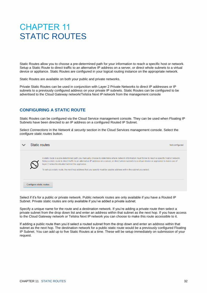
CONFIGURING A STATIC ROUTE
Static Routes can be configured via the Cloud Service management console. They can be used when Floating IP Subnets have been directed to an IP address on a configured Routed IP Subnet. Select Connections in the Network & security section in the Cloud Services management console. Select the configure static routes button.
Select if it’s for a public or private network. Public network routes are only available if you have a Routed IP Subnet. Private static routes are only available if you’ve added a private subnet. Specify a unique name for the route and a destination network. If you’re adding a private route then select a private subnet from the drop down list and enter an address within that subnet as the next hop. If you have access to the Cloud Gateway network or Telstra Next IP network you can choose to make this route accessible to it. If adding a public route then you’d select a routed subnet from the drop down and enter an address within that subnet as the next hop. The destination network for a public static route would be a previously configured Floating IP Subnet. You can add up to five Static Routes at a time. These will be setup immediately on submission of your request.

CHAPTER 11 STATIC ROUTES 33
Once the routes are active, you can modify or remove them via the Cloud Services management console and add more Static Routes. Changes will be applied immediately upon submission.
Please be aware that thefollowing three RFC 1918 summary routes may not be advertised from your cloud
tenancy into your Telstra IP network.
If your cloud tenancy advertises these summary ranges towards the Telstra IP network they will be filtered out by
Telstra’s Cloud Gateway.
10.0.0.0/8
172.16.0.0/12
192.168.0.0/16
Any subset or supernet of these summary routes can be advertised. For example:
You can advertise 192.168.0.0/17 and 192.168.128.0/17 from your cloud tenancy towards the Telstra IP
network instead of 192.168.0.0/16.
You can advertise 172.16.0.0/13 and 172.24.0.0/13 instead of 172.16.0.0/12.
You can advertise 10.0.0.0/9 and 10.128.0.0/9 instead of 10.0.0.0/8.
More information about this can be found in the Cloud Gateway Technical Guide: https://cloud.telstra.com/res/pdf/cloud-gateway-technical-guide.pdf

CHAPTER12 FIREWALLS 34
CHAPTER12 FIREWALLS
Firewalls are provided for both your public and private networks to increase the security and privacy of your virtual
servers.
Both private networks and public networks are created with default firewall rules – all network traffic is allowed by
default on the private network, and all traffic is blocked by default on the public network. These rules can be
updated via the Cloud Services management console.
Firewalls can be used to group and separate virtual servers into zones and tiers and control traffic through your
public and private interconnect to your virtual servers. To see examples of this, refer to our Infrastructure Design
Guide.
A single firewall can control traffic for a single compute service, within a single virtual data centre for either private
or public networks.
Firewalls can be configured using various configurations. The source and destination for traffic needs to be
specified per firewall rule. This can be done using the settings: ‘Any’, ‘All virtual servers’ or ‘Specific IP ranges’.
Refer to the Adding a firewall rule section.

CHAPTER12 FIREWALLS 35
You’ll need to configure firewall rules on both firewalls to allow communication between virtual servers protected
by different firewalls, in the same virtual data centre.
If you’re dual homing a virtual server, you may already have firewall rules configured in their original network. To
restrict traffic through your second network connection, you’ll need to configure separate firewall rules in the
second network.
You can also create groups – IP sets, applications or application groups that can be applied to firewall rules.
Groups can be reused within a subscription, saving you the effort of repeatedly creating multiple rules. See the
Adding a group section.
ACCESSING THE FIREWALLS SECTION
You can access the Firewalls page of the management console under the Network & security section.
There are two tabs on the Firewall page:
1. Rules
2. Groups
THE RULES TAB
This is where you can configure firewalls on both your public and private networks.
From the rules tab, you can:
Add firewall rules
Edit firewall rules
Re-order firewall rules
Remove firewall rules
CONFIGURING A FIREWALL RULE
Locate the firewall you want to configure by selecting either the private or public instance in the Rules tab. Use the
search bar if you need help finding an existing firewall rule.
You can confirm your active firewall rules by clicking View active rules.

CHAPTER12 FIREWALLS 36
ADDING A FIREWALL RULE
To add a firewall rule, select the Add rule button above your firewall table on the right.
Configure firewall rules by specifying:
Action to allow or deny traffic
Source
Destination
Ports and protocols
When configuring the firewall’s source and destination you can specify the following criteria:
Any – anything including IP addresses inside and outside of the virtual data center.
All virtual servers – for a public firewall, this is a maintained group of assigned public IP addresses and public
IP subnets within a virtual data center. For a private firewall, this is a group containing all private IP addresses
assigned to private subnets in the Cloud Services management console. This exclude IP addresses being
used on Layer 2 Private Networks because they are unknown to us.
Specific IP addresses – allows you to specify IP addresses by single IP address, IP range, IP subnet or an IP
set (a group of IP addresses, ranges and/or subnets).
When configuring ports and protocols you can choose to allow/deny all or select:
Specific ports and protocols
Applications – a collection of ports of the same protocol
Application groups – a collection of more than one application. This can contain a variety of protocols.
The available port/protocol combinations are:

CHAPTER12 FIREWALLS 37
PROTOCOL PORT
TCP AND/OR UDP Any port or port range
FTP 21
ICMP Not applicable
If you select FTP, the firewall will be configured to perform deep packet inspection and allow access on ports that
are dynamically negotiated.
Remember to submit your changes once you’ve finished configuring you rules.
EDITING FIREWALL RULES
To launch the Edit firewall rule window, select Edit next to the firewall rule you would like to modify.
Change the details in the fields you would like to modify and then Add rule to request.
The modified rules will be highlighted blue in the firewall rules table.
You’ll need to select Apply changes for the rule edit to take effect.
RE-ORDERING FIREWALL RULES
Select Edit for the firewall rule you want to reorder.
If no other changes are needed apart from reordering, select Add rule to request.
Drag the firewall rule to the desired position.
Select Apply changes.
REMOVING FIREWALL RULES
Select Remove next to the firewall rule you would like to delete.
You’ll need to select Apply changes for the rule edit to take effect.
Your firewall is provided by default. If you choose no protection remove firewall rules or add a single permissive
rule.
THE GROUPS TAB
There are 3 categories of groups that can be created.
IP set – a collection of IP addresses, subnets or ranges in any sequence or combination.
Application – a collection of ports of the same protocol.
Application group – a collection of more than one application. This can contain a variety of protocols.
Once you’ve chosen the type of group you’d like to create, you can:
Add groups

CHAPTER12 FIREWALLS 38
Edit groups
Delete groups
After you’ve created a group, it can be assigned to as many firewall rules as you choose, within your subscription.
CONFIGURING A GROUP
Select the type of group you want to configure. Use the search bar in each section if you need help finding an
existing group.
ADDING A GROUP
Select the create button next to the group category (e.g. Create an IP set).
Enter a name for your group. This name must be unique within your subscription.
If you’re creating an IP set – add at least one of the following values. There is no limit to how many IP
addresses, ranges or subnets can be added to an IP set.
If you’re creating an application – you must select a single protocol, either TCP or UDP, per application.
Combination of protocols are not allowed*. There is no limit on port numbers or ranges that can be added to an
application.

CHAPTER12 FIREWALLS 39
*create an application group for a combination of protocols.
If you’re creating an application group – creating an application is a pre-requisite for an application group.
Select from existing applications to create your group. You can create application groups with a combination of
both TCP and UDP protocols.
You can choose to add comments to your group. This can help you identify the group when you’ve created many
similar groups.
Select Submit.
EDITING GROUPS
Select the group you’d like to modify to view the group details. Select Edit.
Change the details in the fields you would like to modify.
Select Submit.
DELETING GROUPS
Select the group you’d like to modify to view the group details. Select Delete.
ASSOCIATION OF NETWORKS WITH FIREWALLS
A public firewall controls the flow of traffic on:
Public shared networks
Dedicated public subnets (Routed and Floating IP Subnets)
Private networks attached to NAT Gateway
The private firewall controls the flow of traffic on:
Private IP subnets
Private Layer 2 networks
LOAD BALANCERS AND FIREWALLS
Load balancers, whether private or public, are outside the firewall rules configured in the Cloud Services
management console. Firewalls cannot be used to control traffic inbound to any IP or service used on the load
balancer.
Firewalls can limit the flow of traffic from the load balancer to your virtual servers. The source address of the
forwarded traffic will be the transit interface address of the load balancer. This will be communicated to you when
the load balancer is configured. For a private load balancer this will usually be the second usable IP of an
interconnect subnet provided when the first private load balancer was requested. For a public load balancer it is
from an interconnect subnet that we provide.
As the firewall rule is applied at the virtual server level, if rules are limiting incoming connections you need to
consider a rule like “LB-real-ip -> virtual_server port 80 allow”. This would allow traffic from any port of the supplied
real IP address of the load balancer to the HTTP port of your virtual server.

CHAPTER 13 LOAD BALANCERS 40
CHAPTER 13 LOAD BALANCERS
Add load balancers to your network to distribute traffic to multiple virtual servers. A single load balancer can
service your Virtual Server (Dedicated) Gen2 service within a network.
CREATE A NEW LOAD BALANCER
You can request load balancers from the Load balancers page in the Network & security section of the Cloud
Services management console.
You’ll need to choose which network the load balancer should be created in.
If you choose a public load balancer, we’ll allocate a public IP address to the load balancer.
If you choose a private load balancer, you’ll need to provide an IP address. This IP address can’t come from any
IP subnets that you have allocated to your private network. You need to provide the load balancer interconnect
subnet for your private network. This IP subnet should be unique and not overlap or conflict with any allocated
private IP subnets. It also needs to be unique within your organisation.
Please provide a name for the load balancer application you'd like to set up.
Select the application protocol type from the dropdown menu.
The virtual IP port and server port numbers will be automatically entered depending on the application protocol
type you selected. You can also change these numbers.
If you select other from the Application protocol type dropdown, another dropdown will appear to give you the
option to specify the transport protocol (TCP or UDP). You’ll need to enter the Virtual IP port and server port
numbers yourself.
Specify which virtual server(s) will be included in the load balancing pool.
If you select X-Forwarded-For (XFF), the originating IP address of the client connecting to your web server through
load balancers will be identified. This is available for HTTP and HTTPS protocols
SELECT THE LOAD BALANCING METHOD
The methods include:
Least connections: Directs traffic to the virtual server with the least number of current connections.
Round robin: Directs traffic to each virtual server in sequence.
Hash: Assigns traffic based on the source IP address. Hash uses persistent connections to the same server, so
can be used when standard persistence methods (below) are not applicable (e.g. non-HTTP traffic or if you require
persistence longer than sticky source IP’s 24 hours). This method can produce uneven distribution.
If you selected either Least connections or Round robin as your load balancing method, you can choose to add a
persistence option. If you choose None, traffic will be directed according to the specified load balancing method.

CHAPTER 13 LOAD BALANCERS 41
Persistence options offers ways to send traffic to the same virtual server.
Sticky source IP: Maintains stickiness using the source IP address, but only for 24 hours.
Persistent cookie: Maintains stickiness using a cookie stored in the user’s browser. When you choose this method,
you can then select to have the cookie time-out in seconds, up to one year.
Session cookie: Identifies traffic using a cookie, but only for a browser session.
You will only be able to select the Persistent cookie and Session cookie options if you specified your application
protocol as HTTP.
SSL OFFLOADING
Secure Sockets Layer (SSL) offloading improves the performance of your service by designating a separate
device to process the encryption of sensitive data.
To enable SSL Offloading you must first request a load balancer. Once your load balancer is active, return to the
load balancer configuration page to submit a request for SSL offloading.
When configuring SSL offloading you must upload your own certificate and assign it to each Virtual IP (VIP). You
can upload multiples and assign a certificate per VIP. Each certificate must be added to each network – public or
private – separately.
Certificates must be entered in PEM format – the standard format for OpenSSL and other SSL tools. Once you
submit the form, the certificates will be uploaded immediately. We do not handle certificate data. You are
responsible for adding and updating, including managing certificate expiry.
HEALTH MONITORING
Health monitoring helps a load balancer determine which virtual servers are and aren’t available. Select the health
monitoring method you would like to use:
Ping: A Ping health check sends an ICMP echo request packet to the server and awaits an echo response. If you
have configured a firewall, your virtual server may not respond to pings unless you allow it and may be incorrectly
labelled as ‘down’ as a result.
TCP/UDP (socket open): A TCP/UDP (socket open) health check does a basic check of the server port (e.g. TCP
port 80) to see if a virtual server will accept a connection.
HTTP any code: A HTTP any code health check initiates a HTTP request to the virtual server and waits a
response of any code. The virtual server will be marked as up as long as the HTTP server can reply to the request
(including if it replies with error codes such as 404). If you want to use the root URI, enter ‘/’.
HTTP OK code: A HTTP OK code health check is similar to HTTP any code, but only marks the server as ‘up’ if
receives HTTP codes of 200, 201 or 202. If you want to use the root URI, enter ‘/’.
Supported load balancer port and protocol configurations are limited to the options provided through the Cloud
Services management console. Available options are:

CHAPTER 13 LOAD BALANCERS 42
APPLICATION PROTOCOL VIP PORT SERVER PORT
HTTP 80 80
HTTPS 443 443
FTP 21 21
DNS 53 53
SMTP 25 25
SSMTP 465 465
IMAP 143 143
IMAP4-SSL 993 993
IMAPS 585 585
POP3 110 110
POP3-SSL 995 995
OTHER (TCP OR UDP) User specified User specified
A load balancer performs a health check every 15 seconds.
A virtual server will be marked as down if it fails a health check three times in a row (45 seconds). Once marked
down, a virtual server will be removed from the load balancing pool and no new traffic will be sent to it.
Existing connections to a failed server will need to time out before it can reconnect to the load balancer and reach
a new virtual server.
Once marked as down, a virtual server will continue to be health checked every 60 seconds. It will be marked as
up if it passes three health checks in a row (180 seconds). Once marked as up, it will be re-added to the load
balancing pool.
SOURCE ADDRESSING FROM LOAD BALANCER
Traffic coming from or through the load balancer, for example health checks and load balancer connections,
will have a source address of the transit interface address of the load balancer. This will be communicated
when the first load balancer is configured. It will not have the source address of the IP address being used
for the particular configuration. If applications require the real source address of the traffic then the X-
Forward setting can be used.
MODIFY AN EXISTING LOAD BALANCER
Your existing load balancers will be listed on the Load Balancers page in the Cloud Services management
console.
Select the load balancer you want to modify and select the Modify this load balancer link. Then you only need to
enter the load balancer details you would like to change and submit the request.
MODIFY AN EXISTING LOAD BALANCER WITH SSL OFFLOADING

CHAPTER 13 LOAD BALANCERS 43
Your existing load balancers will be listed on the Load Balancers page in the Cloud Services management
console.
Select the load balancer you want to modify and select the Modify this load balancer link. Select either the Use an
existing public network certificate or Using a new certificate options.
ADDING CERTIFICATES:
Choose the Using a new certificate option, and enter your certificate details – Issued Domain and SSL certificate
key – in the text boxes. The text you enter must be in PEM format, as shown in the image below.
The Issued Domain, Certificate Authority and Certificate Expiry Date fields will be automatically populated.
Enter a name for your certificate. Select Submit request.
REMOVE AN EXISTING LOAD BALANCER
Select the load balancer you want to modify and select the Remove link.
ACCESS YOUR CONFIGURATION DETAILS
Can’t remember the configuration details of your load balancer? Select the load balancer you want to modify and
select the Request current configuration link. The configuration details will be emailed to you.

CHAPTER 14 MANAGEMENT CONNECTION 44
CHAPTER 14 MANAGEMENT CONNECTION
An SSL VPN connection can be used as out-of-bound management access to your virtual service. The SSL VPN
connection allows access to your virtual servers via the private network. It also allows a connection to your
dedicated vCentre.
SSL VPN with your virtual servers takes place via the internet.
SSL VPN MANAGEMENT CONNECTION TO VIRTUAL SERVERS
SSL VPN communicates through a secure client-to-site network tunnel, used to remotely access virtual servers
from the internet over HTTPS.
You can access the SSL authentication page through a web browser. Once authenticated, the security appliance
offers access to the SSL VPN client. After downloading, the client will install and configure itself and establish a
secure SSL connection.
All network traffic will be transmitted using a secure network connect tunnel configured with split tunnelling that
ensures only traffic destined for the virtual server is routed through the tunnel. All other traffic will be routed
through your default network route.
To access your virtual server on your private networks, you’ll need:
Your virtual server’s private network IP address
Access to either Remote Desktop software or a Linux secure shell client
Each virtual data centre location you wish to manage, will require a separate SSL VPN connection.
CONNECT USING REMOTE DESKTOP SOFTWARE
You can connect to a virtual server running Windows using Remote Desktop software.
Enter your server’s IP address and then click Connect.
You will then be prompted to provide your server’s login details.
CONNECT USING A SECURE SHELL CLIENT
You can connect to a virtual server running Linux using a secure shell client, such as Putty.
Enter your server’s IP address, make sure that SSH is selected, and click Open.
You will then be prompted to provide your server’s login details.
You’ll be able to log into the Cloud Services SSL VPN login page after you’ve set up the first SSL VPN user. The
login page address will be provided as part of the welcome emails.
You can connect to your vCenter server over an SSL VPN connection using an upto-date web browser. See
the details in your welcome emails for the IP addresses to use and any configuration needed.

CHAPTER 14 MANAGEMENT CONNECTION 45
It will take up to three business days to set up a SSL VPN connection.
MANAGING SSL VPN USERS
You can manage SSL VPN users from the Management SSL VPN page in the Network & security section of the
Cloud Services management console.
From the SSL VPN section, you can:
Create SSL VPN users
Modify existing SSL VPN users and reset passwords
Remove existing SSL VPN users
CREATE SSL VPN USERS
You’ll need to have a virtual server set up before you can create a SSL VPN user.
Enter the new SSL VPN user’s details and submit the request.
We’ll email you a username and a temporary password for the new user(s).
The new user will need to log into the Cloud Services SSL VPN login page to update the password.
You can create as many SSL VPN users as you need.
You need to create SSL VPN users for each of your virtual data centres.
MODIFY SSL VPN USERS
1. Select the Modify tab.
2. Enter the full name, username or email address to identify the user whose details you would like to
modify. Only fill in the details you would like to change.
3. To reset a SSL VPN user’s password, select the Reset password checkbox and submit the request.
We’ll email you a temporary password.
REMOVE EXISTING SSL VPN USERS
1. Select the Remove tab.
2. Enter the full name, username or email address to identify the user who you would like to remove.
CHAPTER 15 SMTP MAIL RELAY 46
CHAPTER 15 SMTP MAIL RELAY
All outbound email traffic originating from mail servers operating within the cloud must be sent through our SMTP
mail relay service, or alternative software we can provide.
Access to the SMTP mail relay is obtained via the private networks. Once configured any virtual server on a
private network can reach the provided SMTP mail relay IP address.
For the full list of SMTP mail relay fees, see the Pricing Guide for your virtual data centre location.
ACCESS THE SMTP MAIL RELAY SECTION
Access the SMTP mail relay section via the Network & Security Management section.
From the SMTP mail relay details page, you can:
Request an SMTP mail relay
Remove an SMTP mail relay
REQUEST AN SMTP MAIL RELAY
You’ll need to provide one or more valid outgoing email domain names.
After you submit the request to add an SMTP mail relay, we email the mail server set-up details to you.
You’ll then need to configure your software accordingly.
All emails sent via SMTP mail relay must use one of the domain names you specified in the set up process, in the
from field of the email. Using any other domain name will cause the email to be rejected.
REMOVE AN SMTP MAIL RELAY
To stop using our SMTP mail relay service, remove the SMTP mail relay server settings from your virtual servers.
You will no longer be able to send emails from your virtual servers.
ALTERNATIVES TO SMTP MAIL RELAY
We allow the use of several software alternatives to using our SMTP mail relay service.
Microsoft Office 365, Symantec.Cloud and internet protection (email) can be provided and supported through
Telstra. For details, click on the names of the software products in the following table.

CHAPTER 15 SMTP MAIL RELAY 47
The following software and outbound port connectivity is permitted:
SOFTWARE PORTS
Microsoft Office 365 25, 465, 587
Symantec.cloud 25
Internet protection (email) 25

CHAPTER 16 APPENDIX A: ROUTING PRIVATE TRAFFIC WITHIN YOUR VIRTUAL HOST 48
CHAPTER 16 APPENDIX A: ROUTING PRIVATE TRAFFIC WITHIN YOUR VIRTUAL HOST
The following information will help you manually route private and internet traffic, when a second network
connection is added to a virtual server. The instructions vary based on the operating system of the virtual server.
For your virtual server to send traffic to your private network, you’ll need to configure Routes on your private
network connection for the following private IP subnets:
10.0.0.0/8
172.16.0.0/12
192.168.0.0/16
Use the first IP address of your private IP subnet as the gateway address.
ROUTING VIRTUAL SERVERS RUNNING WINDOWS
Any virtual server with a second network connection, running any version of a Windows based operating system,
will need three routes to be added:
Route –p add 10.0.0.0 mask 255.0.0.0 <private gateway>
Route –p add 172.16.0.0 mask 255.240.0.0 <private gateway>
Route –p add 192.168.0.0 mask 255.255.0.0 <private gateway>
If you have an office LAN connected to an IPsec VPN tunnel using a public IP subnet as a secured traffic source
subnet, configure routes toward this subnet using your private network vNIC.
Route –p add <IPsec public source subnet> mask <IPsec mask> <private gateway>
The <private gateway> field refers to the first IP address of the private network subnet your virtual server is
connected to. So for example, if your virtual server’s private network subnet is 10.1.0.0/23, then 10.1.0.1 is the
private gateway.
ROUTING VIRTUAL SERVERS RUNNING LINUX
Any virtual server with a second network connection, running any version of a Linux based operating system, will
need three routes to be added:
10.0.0.0 mask 255.0.0.0 <private gateway>
172.16.0.0 mask 255.240.0.0 <private gateway>
192.168.0.0 mask 255.255.0.0 <private gateway>
The <private gateway> field refers to the first IP address of the private network subnet your virtual server is
connected to. For example, if your virtual server’s private network subnet is 10.1.0.0/23, then 10.1.0.1 is the
private gateway.
The next steps required will vary depending on the version of Linux your virtual servers are using.

CHAPTER 16 APPENDIX A: ROUTING PRIVATE TRAFFIC WITHIN YOUR VIRTUAL HOST 49
REDHAT, ORACLE OR CENTOS LINUX OPERATING SYSTEMS - EXAMPLE CONFIGURATION FOR ONE ROUTE
1. Apply the routes to the vNIC connected to your private network. The following instructions assume eth2 for this configuration (adapt this to your specific vNIC)
2. Routes should be configured in /etc/sysconfig/network-scripts/route-eth2 using the following format:
10.0.0.0/8 via <private gateway>
172.16.0.0/12 via <private gateway>
192.168.0.0/16 via <private gateway>
3. If you have an office LAN connected to an IPsec VPN tunnel using a public IP subnet as a secured traffic source subnet, add an additional route to the same file /etc/sysconfig/network-scripts/route-eth2
<IPsec public source subnet> via <private gateway>
4. To apply the previously defined routes, you’ll need to restart the network services using the following command:
# service network restart
SUSE LINUX OPERATING SYSTEM - EXAMPLE CONFIGURATION FOR ONE ROUTE
1. Apply the routes to the vNIC connected to your private network. The following instructions assume eth2 for this configuration (adapt this to your specific vNIC).
2. Static routes should be configured in /etc/sysconfig/network/ifroute-eth2 using the following format:
10.0.0.0/8 <private gateway> - eth2
172.16.0.0/12 <private gateway> - eth2
192.168.0.0/16 <private gateway> - eth2
3. If you have an office LAN connected to an IPsec VPN tunnel using a public IP subnet as a secured traffic source subnet, add an additional route to the same file /etc/sysconfig/network/ifroute-eth2
<IPsec public source subnet> <private gateway> - eth2
4. To apply the previously defined routes, you’ll need to restart the network services using the following command:
# /etc/init.d/network restart