Closure of the Failed Ash Dredge Cell at Kingston – The ...
24
Closure of the Failed Ash Dredge Cell at Kingston – The Engineering Challenge Vernon J. Dotson, Jr. 1 , Darrell E. Herron, PE 2 , Alan F. Rauch, PhD, PE 2 , and Michael J. Steele, PE 2 1 Tennessee Valley Authority, 1101 Market Street, Chattanooga, Tennessee 37402 2 Stantec, 1409 North Forbes Road, Lexington, Kentucky 40511 KEYWORDS: TVA Kingston, ash pond closure, design management ABSTRACT At TVA’s Kingston Fossil Plant, recovery of coal ash released in the 2008 dike failure is nearing completion. When finished, roughly 12 million cubic yards of combustion products will be capped and retained within a new stabilized perimeter. Closure of a large coal ash facility requires engineering solutions that address environmental regulations, site constraints, and plant operational needs. Following the catastrophic failure, the Kingston team faced additional challenges, including the need to re-build public trust, regulatory oversight under CERCLA, and a compressed recovery schedule. A major design challenge was seismic performance, as large regional earthquakes could liquefy the saturated ash and deeper alluvium. To contain these materials, slurry walls are being built around the two-mile circumference of the facility. Advanced engineering analyses are required to design this feature. Perimeter containment was divided into eight segments, with the design sequenced to stay ahead of an aggressive construction schedule. In addition to a comprehensive quality control program, construction requires significant engineering support. Concurrent with perimeter stabilization, recovered ash is being stacked inside the landfill. An instrumentation network is used to monitor stability, to avoid triggering another failure. The design for the final cover includes a flexible membrane liner, with erosion and storm water management. All of this complex engineering is subject to on-going, detailed, independent peer review at multiple levels. A separate value engineering program was also completed. This paper highlights the organization and management of this engineering effort, and provides valuable lessons for planners of other complex ash pond closure projects. PROJECT OVERVIEW The December 22, 2008 release at the Tennessee Valley Authority’s (TVA’s) Kingston Fossil Plant displaced 5.4 million cubic yards of coal ash. The released ash covered roughly 300 acres, directly impacted about 40 area homes, destroyed a highway and railroad line, and closed the adjacent Emory River. Fortunately, no one was injured. This environmental disaster required swift and immediate action from TVA, to prevent the released ash from moving farther downstream, to dredge ash from the river, and to 2013 World of Coal Ash (WOCA) Conference - April 22-25, 2013 in Lexington, KY http://www.flyash.info/
Transcript of Closure of the Failed Ash Dredge Cell at Kingston – The ...
Closure of the Failed Ash Dredge Cell at Kingston – The Engineering Challenge
Vernon J. Dotson, Jr.1, Darrell E. Herron, PE2, Alan F. Rauch, PhD, PE2, and Michael J. Steele, PE2 1Tennessee Valley Authority, 1101 Market Street, Chattanooga, Tennessee 37402 2Stantec, 1409 North Forbes Road, Lexington, Kentucky 40511 KEYWORDS: TVA Kingston, ash pond closure, design management ABSTRACT At TVA’s Kingston Fossil Plant, recovery of coal ash released in the 2008 dike failure is nearing completion. When finished, roughly 12 million cubic yards of combustion products will be capped and retained within a new stabilized perimeter. Closure of a large coal ash facility requires engineering solutions that address environmental regulations, site constraints, and plant operational needs. Following the catastrophic failure, the Kingston team faced additional challenges, including the need to re-build public trust, regulatory oversight under CERCLA, and a compressed recovery schedule. A major design challenge was seismic performance, as large regional earthquakes could liquefy the saturated ash and deeper alluvium. To contain these materials, slurry walls are being built around the two-mile circumference of the facility. Advanced engineering analyses are required to design this feature. Perimeter containment was divided into eight segments, with the design sequenced to stay ahead of an aggressive construction schedule. In addition to a comprehensive quality control program, construction requires significant engineering support. Concurrent with perimeter stabilization, recovered ash is being stacked inside the landfill. An instrumentation network is used to monitor stability, to avoid triggering another failure. The design for the final cover includes a flexible membrane liner, with erosion and storm water management. All of this complex engineering is subject to on-going, detailed, independent peer review at multiple levels. A separate value engineering program was also completed. This paper highlights the organization and management of this engineering effort, and provides valuable lessons for planners of other complex ash pond closure projects. PROJECT OVERVIEW The December 22, 2008 release at the Tennessee Valley Authority’s (TVA’s) Kingston Fossil Plant displaced 5.4 million cubic yards of coal ash. The released ash covered roughly 300 acres, directly impacted about 40 area homes, destroyed a highway and railroad line, and closed the adjacent Emory River. Fortunately, no one was injured. This environmental disaster required swift and immediate action from TVA, to prevent the released ash from moving farther downstream, to dredge ash from the river, and to
2013 World of Coal Ash (WOCA) Conference - April 22-25, 2013 in Lexington, KYhttp://www.flyash.info/
provide for long-term disposal of the recovered materials. An aggressive schedule was established for ash recovery and site closure. TVA did not make any of these decisions alone, however, as these activities required stakeholder confidence that the recovery and closure plan would address public concerns and meet appropriate standards. A framework was established with joint project management by the US Environmental Protection Agency (EPA), the Tennessee Department of Environment and Conservation (TDEC), and TVA. In addition to regulatory oversight by these agencies, engineering designs were subjected to multiple independent peer reviews. Based on a careful evaluation of alternatives, the Kingston Recovery Project (KRP) management team decided to ship about half of the recovered ash to an off-site landfill for disposal, stack the remaining ash within the footprint of the failed area and the adjacent ash pond, and then close the Kingston coal ash facilities. During the first 17 months following the failure, nearly 3 million cubic yards of ash were recovered and shipped by rail to an approved solid waste landfill in Perry County, Alabama. During this initial phase of the recovery, the site was preparing for ash stacking operations. Critical infrastructure was established to support operations, including haul roads, processing areas, geotechnical instrumentation, and monitoring networks. A large-scale test embankment program was completed, to demonstrate how reclaimed ash could be safely re-stacked across the failed footprint. While these activities were taking place, the engineering team developed the conceptual design for site closure. Current Tennessee environmental regulations require that new landfills be designed to withstand earthquake loads. At Kingston, the design earthquake will cause extensive liquefaction in the deeper ash and alluvial soils. The need to establish seismic containment was the primary driver in the closure design, which includes a stabilized perimeter around the full circumference of the site. The KRP management team developed a schedule framework for engineering and construction. Design documents, subject to review and approval by EPA and TDEC, are typically issued “just-in-time” for the start of construction. Meeting these deadlines is difficult for the engineering team, given the need to demonstrate seismic performance and the complexity of the design analyses. The schedule must also allow time for the review sequence, which includes both independent peer and regulatory agency reviews. This paper describes many of the engineering and management challenges faced in this $1.2 billion project. As of April 2013, engineering work on the design packages is complete. The stabilized perimeter has been constructed around 60% of the site. The last of the ash released in the failure will be recovered before summer of 2013. Construction of the final cap and cover, which will begin later this summer, is scheduled for completion in late 2014.

THE PROJECT TRIPOD Like all large capital projects, the KRP is subject to the competing demands represented by the three legs of the “Project Tripod” (Figure 1): quality, schedule, and cost. While TVA has committed substantial funds to the recovery and closure project, budgets are not unlimited; prudent management and economic designs are necessary to contain project costs. Schedule is a particularly important measure of project success, given the environmental impacts of the failure and TVA’s public commitments for recovery. The third element, quality, covers a variety of project success factors, including the robustness of the design concept, completeness of the design documentation, strength and uniformity within the constructed elements, the record for worker safety, etc. TVA did not compromise on the project goals related to quality, schedule, or cost. However, individual components have been emphasized at various points over the past four years of the project. For example, when projections for the closure design began to exceed project budgets, greater emphasis was placed on reducing design quantities for construction; value engineering was then used to shorten the length of the cost leg on the project tripod. The challenge has been to adjust the lengths of the legs in the project tripod, to maintain a level “line-of-sight” relative to established targets, and ensure the overall, balanced success of the project.
Figure 1. The “Project Tripod” illustrating the components of project success.

SITE HISTORY AND THE 2008 FAILURE Construction at the Kingston plant site began in 1951, with initial generating operations starting in 1954. The plant has nine generating units with a net capacity of 1,400 megawatts, burns coal delivered by rail, and produces up to a thousand tons of ash (combined bottom ash and fly ash) per day. The plant is sited at the confluence of the Emory and Clinch Rivers, west of Knoxville, Tennessee. Both rivers in this area are impounded by Watts Bar Dam on the Tennessee River. The former ash pond complex was established by constructing earthen dikes across the adjacent, shallow embayment of the Emory River, thereby separating the disposal area from Watts Bar Reservoir. Ash was sluiced to the ash pond until 1984, when TVA began building elevated “dredge cells” to increase storage capacity. Ash slurry was hydraulically dredged from the ash pond and pumped alternately to three cells located on the western side of the ash pond complex (Figure 2). Dredging operations continued over the next 19 years, with the dredge cells being successively raised in steps with upstream dikes. Cells 2 and 3 were eventually combined into a single cell.
Figure 2. Aerial imagery of the ash pond facilities in 1996 and 2008.
In 2003, a superficial slip occurred in the dikes along Swan Pond Road, and dredging operations into Cells 1 and 2 were suspended. An Emergency Dredge Cell (Figure 2) was constructed and became the primary disposal cell used over the next few years. Late in 2005, Cell 1 was returned to service. Another localized, shallow slip occurred in the western dikes in November of 2006. While slope repairs were implemented, all material was again dredged into the Emergency Dredge Cell. Operations in Cells 1 and 2 were then continued until the 2008 failure. The Kingston dredge cell failed in the early morning hours of December 22, 2008. At the time of the failure, the crest of the facility was approximately 60 feet higher than Swan Pond Road, and 78 feet above Watts Bar Reservoir. The breech began in the northern
Cell 2
Emergency Dredge Cell
Cell 1
2008
1000 ft N
Cell 2
Cell 3
Cell 1
Ash Pond
Swan Pond Road
1996
1000 ft N

corner of the site, with retrogressive slope failures that eventually involved most of the dredge cell. About 5.4 million cubic yards of liquefied ash slurry ran out several thousand feet to the north and east, filling the adjacent lake embayments. Figure 3 compares the site before and after the failure. The public highway and railroad along the western side of the site were devastated, and the Emory River channel was filled with ash. The dikes around the ash pond on the eastern half of the site held, although one corner at the northern end was cracked where impacted by the ash flow.
Figure 3. Comparison of aerial imagery before and after the 2008 failure.
In the days immediately following the failure, TVA concentrated on providing support and services to the local community, and especially those residents directly affected by the failure. Initial construction efforts were centered on restoring the local infrastructure and stabilizing the site. Swan Pond Road was re-built and opened to traffic. The adjacent railroad line, which supplies coal to the generating station, was also re-built. TVA retained AECOM to conduct a root cause analysis for the failure (Walton and Butler 2009), which concluded that the collapse was initiated within a thin, soft stratum at the base of the old ash deposits. Creep movements within this layer precipitated an undrained slope failure, and that resulted in static liquefaction of the saturated, stored ash deposits.
1000 ft
N
1000 ft
N

REGULATORY OVERSIGHT FOR THE RECOVERY On January 12, 2009, TDEC issued a Commissioner’s Order in response to the ash release. TVA was required to develop a plan for the comprehensive clean-up of the ash, plus restoration of the damaged natural resources. This was followed in May of 2009 with the signing of an Administrative Order on Consent (AOC) between TVA and EPA. The AOC provided regulatory framework under the Comprehensive Environmental Response, Compensation, and Liability Act of 1980 (CERCLA, also known as the Superfund program). This program was chosen as the regulatory framework due to its comprehensive human health and ecological risk assessment process, and its proven capacity to engage multiple stakeholders in complex environmental projects. However, the KRP did not receive outside funding under the CERCLA program; TVA committed to paying for 100% of the project costs. Together, the TDEC and EPA orders increased the number of stakeholders and meant that the recovery would be managed “by committee”, not just by TVA. This approach helped restore the community’s confidence, but created a significant burden on the effort to expedite the design process. The engineering analyses and design, particularly issues related to ground water and seismic performance, were scrutinized by the regulatory agencies and their technical experts. During the development of the closure concept, the engineering team provided frequent and regular briefings (typically every few months) at the project site. These meetings were intended to help the various reviewers understand the design assumptions, material properties, numerical analyses, and other details of the closure design as it was developed. The meetings and on-site interactions with the regulatory agencies were highly successful in keeping the project moving. Nearly all questions were addressed prior to submittal of the actual design packages for formal review, which eliminated potential last-minute delays just as construction was set to begin on individual components of the closure. ASH RECOVERY OPERATIONS The CERCLA framework broke the project into three phases:
• Phase 1, Time-Critical Ash Recovery, involved restricting ash migration downstream, dredging ash from the river, transporting this material to an off-site, approved landfill, and restoring the flow of the Emory River.
• Phase 2, Non-Time-Critical Ash Recovery, includes removing the remaining ash from outside the facility boundary, placing it within the stabilized perimeter of the former ash pond and dredge cell facility, and closing the landfill.
• Phase 3 includes the restoration of the natural resources affected by the failure. Time-Critical Operations were performed under full-time, on-site supervision by EPA and TDEC. One of the first activities was to construct a subsurface, rock dike across the

Emory River just below the failure. The dike was constructed to limit the downstream migration of displaced ash, lessening the impacted area. However, the dike and ash that filled the main channel of the Emory River posed a significant risk for upstream flooding. The Emory does not have an upstream dam to retain high flows, and this flooding risk was present until the channel was restored and the cut-off dike removed. Ash was removed from the river by mechanical and hydraulic dredging (Figure 4). Commencing in January 2009, dredging operations continued around the clock, typically seven days per week. The materials removed included ash, displaced soils, and sandy river bottom sediments. Processing areas were established to de-water and condition the materials prior to off-site shipment. Dredge water was circulated though sluice trenches excavated in the area immediately south of the ash pond, and the ash pond was used to further remove suspended solids prior to discharge of water back to the river. The recovered ash was dipped out of the sluice trench, moved, turned, and stacked multiple times to promote drainage and evaporation, until the water content was low enough for shipment.
Figure 4. Dredging and load-out to railcars during Time-Critical ash removal.
Time-Critical ash removal was completed in May 2010, just 17 months after the failure. Off-site shipment and disposal of the Time-Critical ash was completed seven months later, in December 2010. Ash was transported over 300 miles by rail (in hopper cars lined with plastic to contain seepage water) to the Arrowhead Landfill in Perry County, Alabama. In the end, about 3 million cubic yards of Time-Critical ash were transported offsite via 40,000 rail cars in 414 train shipments. While the Phase 1 dredging operations were underway, the joint project team developed plans for disposal of the ash to be recovered during the Non-Time-Critical phase. The considered options varied from off-site shipment and disposal of all ash, to placing the recovered materials back within the footprint of the failed cell, with various volumes and geometries considered for each. Given the high cost of off-site shipment and the burden that would be placed on public infrastructure, the consensus decision among the stakeholders was to return all ash recovered during the Non-Time-Critical
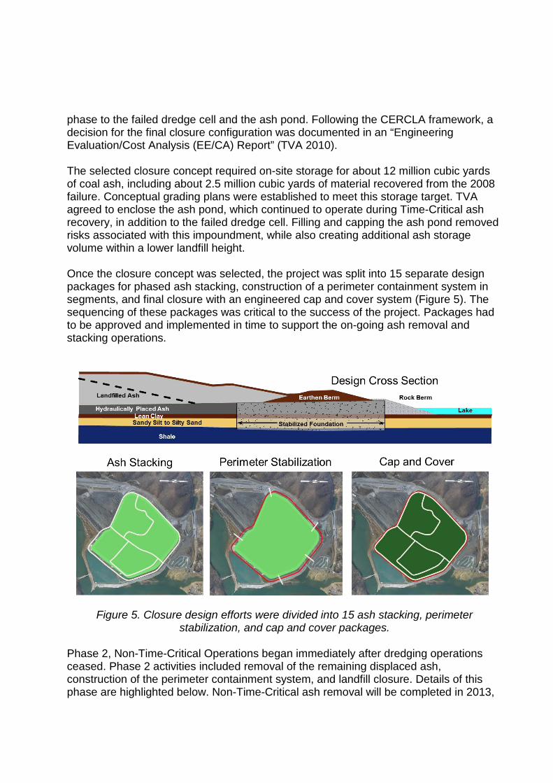
phase to the failed dredge cell and the ash pond. Following the CERCLA framework, a decision for the final closure configuration was documented in an “Engineering Evaluation/Cost Analysis (EE/CA) Report” (TVA 2010). The selected closure concept required on-site storage for about 12 million cubic yards of coal ash, including about 2.5 million cubic yards of material recovered from the 2008 failure. Conceptual grading plans were established to meet this storage target. TVA agreed to enclose the ash pond, which continued to operate during Time-Critical ash recovery, in addition to the failed dredge cell. Filling and capping the ash pond removed risks associated with this impoundment, while also creating additional ash storage volume within a lower landfill height. Once the closure concept was selected, the project was split into 15 separate design packages for phased ash stacking, construction of a perimeter containment system in segments, and final closure with an engineered cap and cover system (Figure 5). The sequencing of these packages was critical to the success of the project. Packages had to be approved and implemented in time to support the on-going ash removal and stacking operations.
Figure 5. Closure design efforts were divided into 15 ash stacking, perimeter stabilization, and cap and cover packages.
Phase 2, Non-Time-Critical Operations began immediately after dredging operations ceased. Phase 2 activities included removal of the remaining displaced ash, construction of the perimeter containment system, and landfill closure. Details of this phase are highlighted below. Non-Time-Critical ash removal will be completed in 2013,

with final site closure projected to be complete by the end of 2014. Phase 3 restoration efforts will continue through the spring of 2015. The 2008 failure disrupted operations at the Kingston generating station. Seven of the nine units were removed from service within a few days after the failure. Within two weeks, these units were returned to service as needed. Recognizing the risks associated with operating ash ponds at the site, TVA decided to convert the Kingston facility to a dry ash handling system. Construction of this system was completed in December 2011, and production ash is no longer directed to the ash pond complex. TVA plans to construct a new landfill to store future production ash; in the interim, production ash is being stored temporarily in an area immediately south of the former dredge cell. ASH STACKING Due to the aggressive recovery schedule and lack of alternative space for storage, recovered ash was stacked within the landfill interior prior to and during construction of the stabilized perimeter. The ash was moisture conditioned, placed in lifts, and compacted with engineering controls. In places, up to about 35 feet of ash fill was allowed, with top elevations at least two feet below conceptual final grade configurations. The stacking design packages provided for stable ash disposal within the site interior. Maximum 6:1 (horizontal to vertical) out slopes were specified. Interim geometry was analyzed for slope stability under drained and undrained conditions, with particular attention paid to the potential for deep seated failures like the 2008 event. With no warning at the surface, excess pore pressures generated by embankment stacking can trigger undrained failures in the underlying foundation ash. A test embankment program was completed during Phase 1 of the recovery, to demonstrate how instrumentation and engineering evaluation could be used to monitor the effects of loading on the deeper ash deposits. About 250,000 cubic yards of conditioned ash were stacked within the footprint of the failed cell (Figure 6), with extensive instrumentation and a well-defined monitoring program. The success of the test embankment program helped to allay concerns that new stacking would trigger another failure.

Figure 6. Aerial view of the completed test embankment.
The ash stacking specifications required the installation of an extensive instrumentation network, and included a detailed plan for monitoring those instruments during construction. Piezometers, slope inclinometers, and settlement plates were utilized to monitor the effects of stacking. Instruments were read daily in the areas of active fill placement, with weekly readings collected in adjacent areas of the site. An on-site professional engineer, designated as the Quality Control (QC) Manager for stacking, was tasked with monitoring this data. For each instrument, trigger limits were established to call attention to high readings and initiate further engineering evaluation. Data recorded by piezometers and inclinometers do not provide a direct measure of slope stability, however, and the established trigger limits were only a guideline. Unsatisfactory conditions were sometimes identified even when the instruments were below the trigger limits, and stable conditions often existed when readings were over the trigger limits. On-going observation and evaluation by the engineering team was required. On several occasions, active stacking was halted or restricted in specific areas when the instruments indicated incipient movements or elevated pore pressures. After a few weeks, when excess pore pressures had dissipated and movements had slowed, ash stacking was allowed to continue. In some instances, interim slopes were flattened or buttressed to stabilize observed movements. The ash was compacted to a minimum 90 percent of standard Proctor maximum dry density, with moisture contents ranging from -2 to +6 percent of optimum (below saturation limits). This range resulted in landfilled ash properties that were consistent with the design assumptions. Given the variable nature of this material, and particularly its sensitivity to moisture content, the observed response of the ash to equipment passage during placement was a critical quality control tool. These observations were used by the QC Manager as a performance basis for adjusting moisture limits.

During the winter construction seasons, it was difficult to meet either the specified moisture limits or the performance requirements. To overcome this challenge without delaying the schedule for ash stacking, spent lime product at 2 to 3% by weight was incorporated into the wet ash, the mix was allowed to cure, and the material was then placed in the landfill. The lime hydrated excess water, helped change the characteristics of the ash, and was an effective soil modification process. Geotechnical testing found little differences in strength of the modified ash, however, so the primary advantage was improved workability during wet periods. During construction and prior to final regulatory release of the site, the storm water runoff is collected using a series of transverse ditches that discharge into armored flumes and drainage structures. To meet environmental regulations, runoff is conveyed to either the existing Stilling Pond or to the temporary settling basin in the Middle Embayment (Figure 7). Storm water routing had to be continually modified during construction, to accommodate both ash stacking and perimeter construction. Furthermore, when the power plant was converted to dry ash handling, production flows to the Ash Pond complex were greatly reduced. Drainage along the south side of the Ash Pond was then modified with the installation of pipes, to create needed spaced for perimeter construction.
Figure 7. Primary site features at the Kingston Recovery Project.
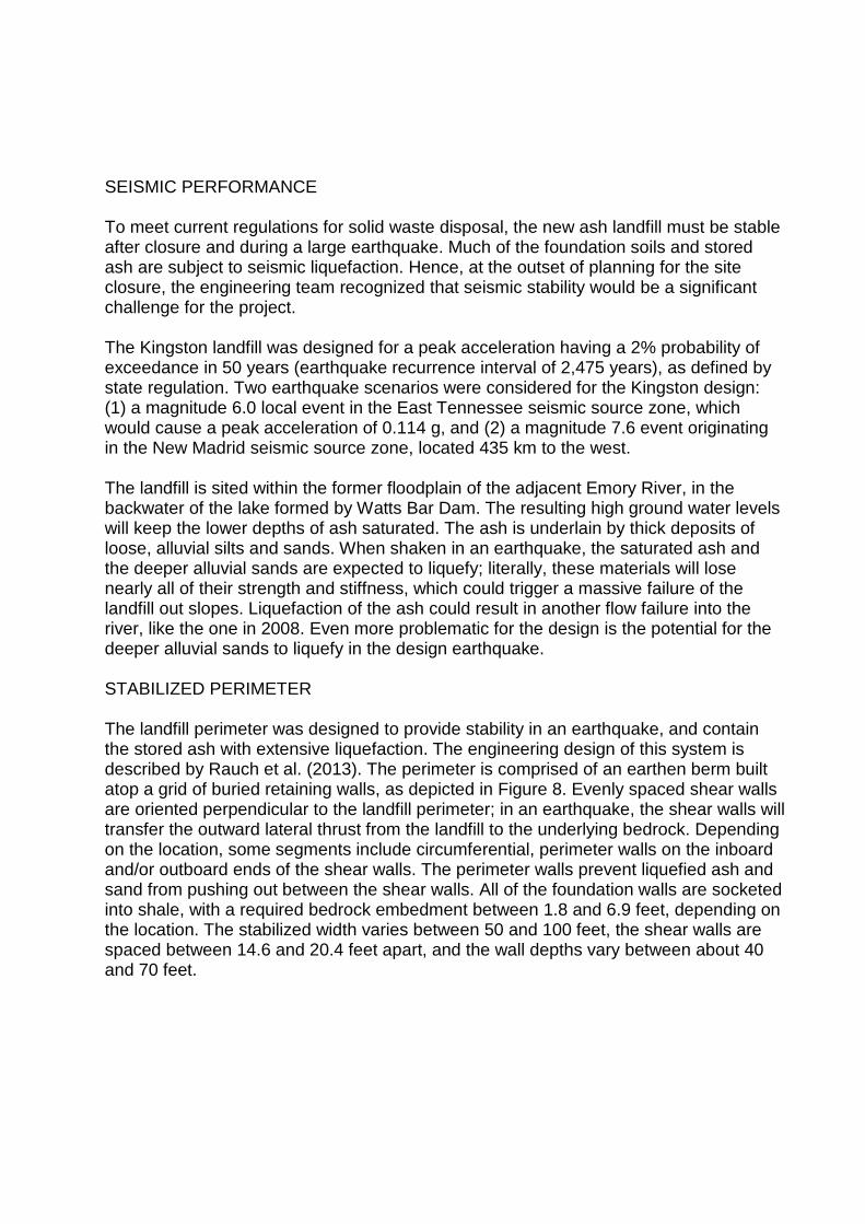
SEISMIC PERFORMANCE To meet current regulations for solid waste disposal, the new ash landfill must be stable after closure and during a large earthquake. Much of the foundation soils and stored ash are subject to seismic liquefaction. Hence, at the outset of planning for the site closure, the engineering team recognized that seismic stability would be a significant challenge for the project. The Kingston landfill was designed for a peak acceleration having a 2% probability of exceedance in 50 years (earthquake recurrence interval of 2,475 years), as defined by state regulation. Two earthquake scenarios were considered for the Kingston design: (1) a magnitude 6.0 local event in the East Tennessee seismic source zone, which would cause a peak acceleration of 0.114 g, and (2) a magnitude 7.6 event originating in the New Madrid seismic source zone, located 435 km to the west. The landfill is sited within the former floodplain of the adjacent Emory River, in the backwater of the lake formed by Watts Bar Dam. The resulting high ground water levels will keep the lower depths of ash saturated. The ash is underlain by thick deposits of loose, alluvial silts and sands. When shaken in an earthquake, the saturated ash and the deeper alluvial sands are expected to liquefy; literally, these materials will lose nearly all of their strength and stiffness, which could trigger a massive failure of the landfill out slopes. Liquefaction of the ash could result in another flow failure into the river, like the one in 2008. Even more problematic for the design is the potential for the deeper alluvial sands to liquefy in the design earthquake. STABILIZED PERIMETER The landfill perimeter was designed to provide stability in an earthquake, and contain the stored ash with extensive liquefaction. The engineering design of this system is described by Rauch et al. (2013). The perimeter is comprised of an earthen berm built atop a grid of buried retaining walls, as depicted in Figure 8. Evenly spaced shear walls are oriented perpendicular to the landfill perimeter; in an earthquake, the shear walls will transfer the outward lateral thrust from the landfill to the underlying bedrock. Depending on the location, some segments include circumferential, perimeter walls on the inboard and/or outboard ends of the shear walls. The perimeter walls prevent liquefied ash and sand from pushing out between the shear walls. All of the foundation walls are socketed into shale, with a required bedrock embedment between 1.8 and 6.9 feet, depending on the location. The stabilized width varies between 50 and 100 feet, the shear walls are spaced between 14.6 and 20.4 feet apart, and the wall depths vary between about 40 and 70 feet.

Figure 8. Rendering of the stabilized perimeter built around the Kingston ash landfill.
The original design concept assumed the walls would be built with deep mixing, where augers are used to mix cement with the in-situ soils. However, the bid package encouraged and allowed for contractors to propose alternate means of construction. The selected bidder (Geo-Con) proposed slurry trench methods to build the walls, and is using high capacity, long-reach, hydraulic excavators to dig trenches supported with slurry (Figure 9). Ripper teeth, installed on the back of the excavator bucket, are used to dig the bedrock sockets. The trench slurry is a mix of blast furnace slag cement and hydrated bentonite (cement-bentonite) that hardens over time after excavation is complete. The required unconfined strength of this material is 200 to 265 psi, depending on the perimeter section. The project team elected to construct four-foot thick walls, and the design allows for varying the shear wall spacing to achieve the specified treatment ratio. To stabilize the entire two-mile perimeter of the landfill, about 520,000 cubic yards of slurry walls will be required. Figure 10 shows an area where the completed walls have been excavated, along the edge of the restored lake.
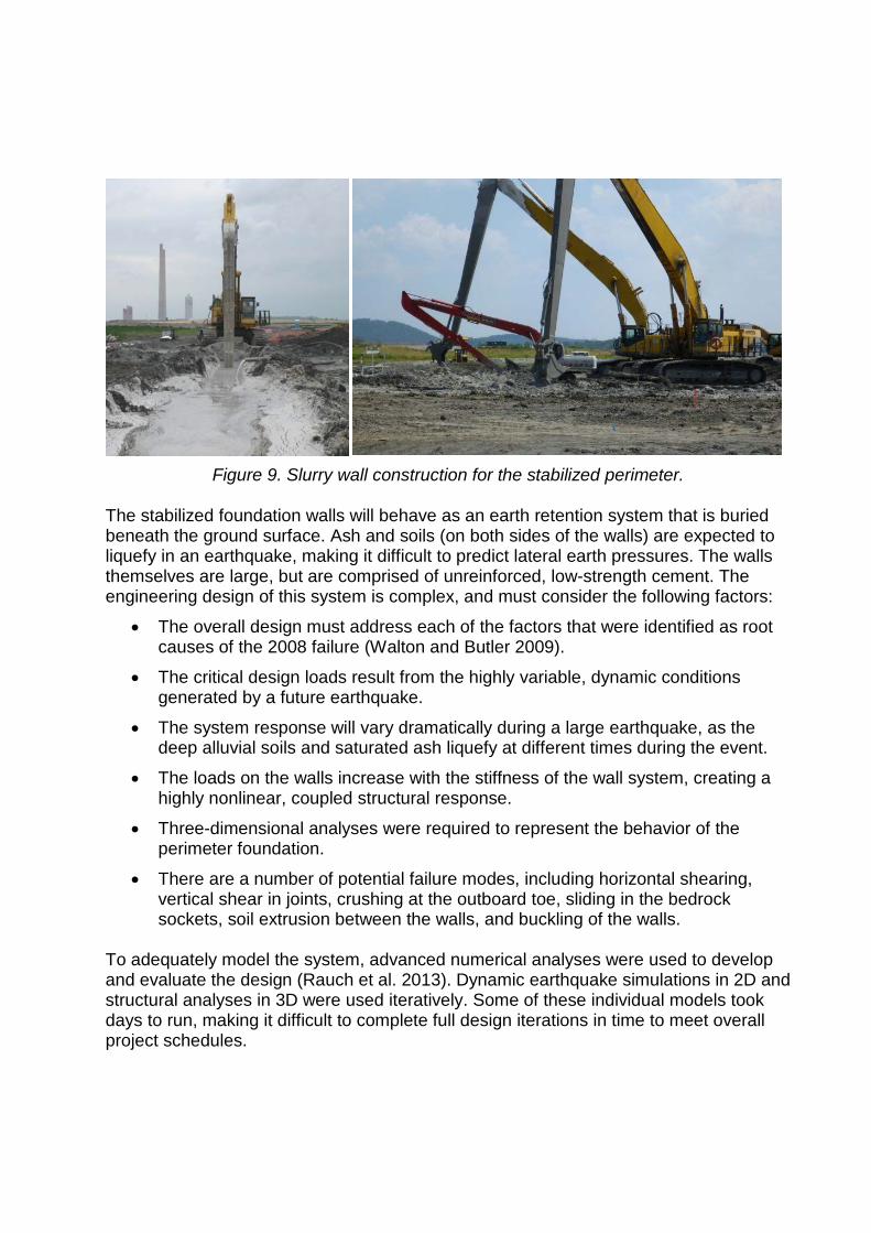
Figure 9. Slurry wall construction for the stabilized perimeter.
The stabilized foundation walls will behave as an earth retention system that is buried beneath the ground surface. Ash and soils (on both sides of the walls) are expected to liquefy in an earthquake, making it difficult to predict lateral earth pressures. The walls themselves are large, but are comprised of unreinforced, low-strength cement. The engineering design of this system is complex, and must consider the following factors:
• The overall design must address each of the factors that were identified as root causes of the 2008 failure (Walton and Butler 2009).
• The critical design loads result from the highly variable, dynamic conditions generated by a future earthquake.
• The system response will vary dramatically during a large earthquake, as the deep alluvial soils and saturated ash liquefy at different times during the event.
• The loads on the walls increase with the stiffness of the wall system, creating a highly nonlinear, coupled structural response.
• Three-dimensional analyses were required to represent the behavior of the perimeter foundation.
• There are a number of potential failure modes, including horizontal shearing, vertical shear in joints, crushing at the outboard toe, sliding in the bedrock sockets, soil extrusion between the walls, and buckling of the walls.
To adequately model the system, advanced numerical analyses were used to develop and evaluate the design (Rauch et al. 2013). Dynamic earthquake simulations in 2D and structural analyses in 3D were used iteratively. Some of these individual models took days to run, making it difficult to complete full design iterations in time to meet overall project schedules.
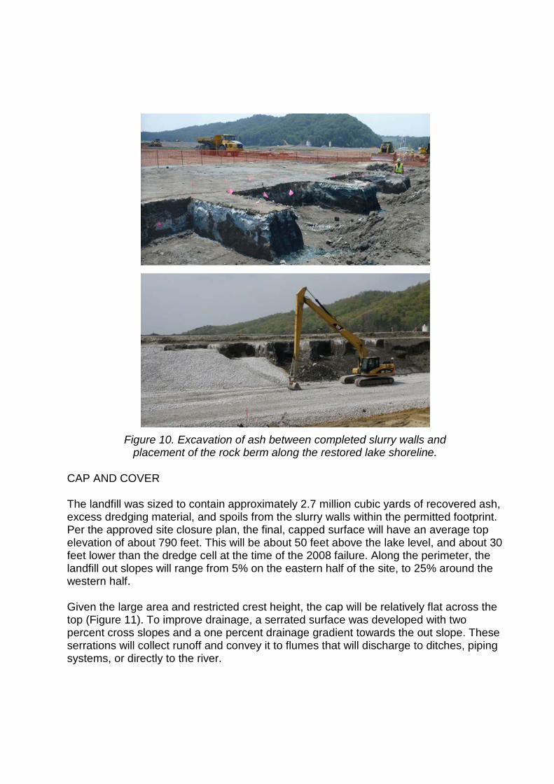
Figure 10. Excavation of ash between completed slurry walls and
placement of the rock berm along the restored lake shoreline.
CAP AND COVER The landfill was sized to contain approximately 2.7 million cubic yards of recovered ash, excess dredging material, and spoils from the slurry walls within the permitted footprint. Per the approved site closure plan, the final, capped surface will have an average top elevation of about 790 feet. This will be about 50 feet above the lake level, and about 30 feet lower than the dredge cell at the time of the 2008 failure. Along the perimeter, the landfill out slopes will range from 5% on the eastern half of the site, to 25% around the western half. Given the large area and restricted crest height, the cap will be relatively flat across the top (Figure 11). To improve drainage, a serrated surface was developed with two percent cross slopes and a one percent drainage gradient towards the out slope. These serrations will collect runoff and convey it to flumes that will discharge to ditches, piping systems, or directly to the river.

Figure 11. Final closure geometry for the Kingston ash landfill.
The final cover will be a modified TDEC defined closure cap utilizing 40 mil LLDPE liner, high capacity geocomposite, and two feet of soil cover. The LLDPE liner was used in lieu of two feet of impervious soil (permeability less than 10-7 cm/sec) plus a foot of vegetative cover, due to scarcity of suitable clay in the area. The alternate cover also results in less infiltration, compared to a soil cover, and is less expensive. Seepage through the cap will be collected by the geocomposite and conveyed to an underdrain system. The cap constitutes a thin plane on top of the stacked ash. There are interfaces between the liner and ash, liner and geocomposite, and geocomposite and soil cover. The cap was evaluated for stability against veneer failure for static drained and undrained conditions, saturated conditions, and pseudostatic seismic conditions. Infiltration through the designed landfill cap was modeled using the HELP model. The site is underlain by a silty to sandy clay deposit of varying thickness, but the clay is not continuous and the landfill is not lined beneath the deepest ash deposits (which date to the 1950s). However, the closed facility will be encircled with the slurry walls and there was some concern about creating a “bathtub effect” (even though this will be an unlined facility). Moderate, long-term mounding of ground water within the landfill is expected, and was modeled using MODFLOW. The predicted long-term ground water surface was used to establish design features, such as the top grade of the perimeter walls, and was used as input to the stability analyses. The perimeter containment system includes an embankment platform detail that will provide an outlet to prevent saturation above critical levels. Potential mounding of the internal ground water was also reduced by removing the circumferential walls along two sides of the site perimeter.
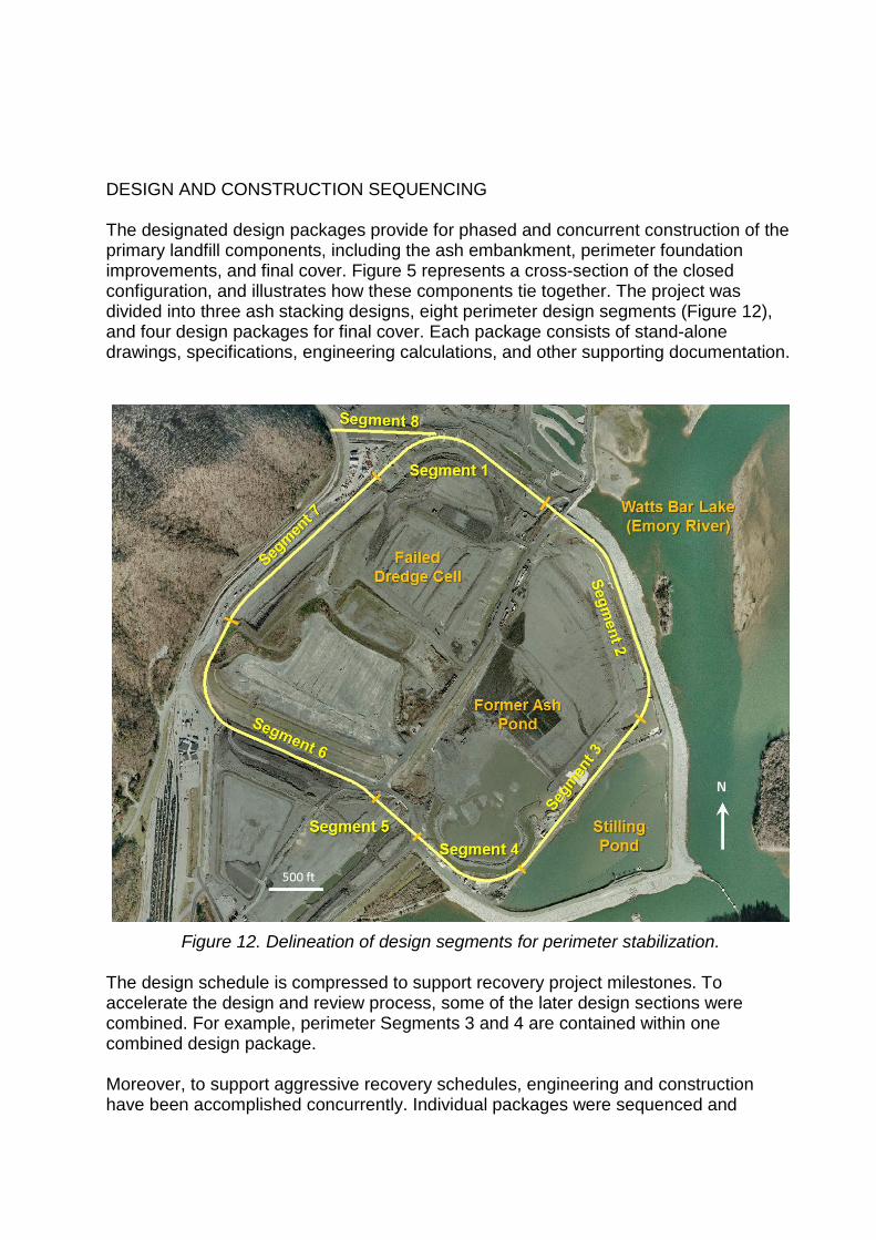
DESIGN AND CONSTRUCTION SEQUENCING The designated design packages provide for phased and concurrent construction of the primary landfill components, including the ash embankment, perimeter foundation improvements, and final cover. Figure 5 represents a cross-section of the closed configuration, and illustrates how these components tie together. The project was divided into three ash stacking designs, eight perimeter design segments (Figure 12), and four design packages for final cover. Each package consists of stand-alone drawings, specifications, engineering calculations, and other supporting documentation.
Figure 12. Delineation of design segments for perimeter stabilization.
The design schedule is compressed to support recovery project milestones. To accelerate the design and review process, some of the later design sections were combined. For example, perimeter Segments 3 and 4 are contained within one combined design package. Moreover, to support aggressive recovery schedules, engineering and construction have been accomplished concurrently. Individual packages were sequenced and

scheduled for “just-in-time” delivery prior to construction, avoiding delays or contractor demobilization. A typical sequence included up to five months of design work, with peer and agency review, and then the start of construction within days after receiving regulatory approval. This process was repeated for all landfill components. The key to success in this environment is for the engineering side to build schedule “float” between final design approval and the start of construction. This goal was especially challenging during initial stages of the project, due to intense peer and regulatory review of the closure concepts (see below). Reduced review times, and increased schedule float, was realized as the reviewers became familiar with the design approach. However, when available float stretched to weeks, there was time to undertake additional design analyses in an attempt to further economize the design. The available float tended to wax and wane throughout the project. However, construction was never delayed waiting for approval of final designs. INDEPENDENT PEER REVIEW In the aftermath of the 2008 failure, it was critically important to build public confidence in the plan for closure of the site. TVA made a commitment to follow current engineering standards for the design, and to subject the design to independent peer review. Formal peer review of all design submittals was performed by GEI Consultants; written responses were provided for all review comments, and the design did not progress until concurrence was reached on all issues. TVA’s Independent Review Board also provided extensive technical review and comment on the design concepts as the project developed. Jacobs Engineering, in their role as the site construction manager, reviewed each design package for constructability. Other outside engineering experts were brought in to provide advice for specific construction issues, as needed. Regulatory review and approval by EPA and TDEC were required before construction proceeded on each design package. The US Bureau of Reclamation performed technical reviews of the design on EPA’s behalf. Throughout the design project, other individuals and organizations provided outside opinions and commentary on the design concepts. Each design package was submitted for formal peer reviews at 30%, 60%, and 90% completion milestones. All questions and comments received in this process were addressed by the design team. Seismic performance and quality control for wall construction received the most attention. Where appropriate, modifications to the design were implemented, but no fatal flaws were discovered. The extensive and continuing review process by so many groups slowed the design process, but greatly helped to establish public trust in the closure concept and design. VALUE ENGINEERING
The design for the first segment of the stabilized perimeter was completed in early 2011, and construction began that summer. Designs for the first three perimeter

segments were complete by the end of 2011, staying just ahead of construction. At this point in the project, TVA asked the design team to consider modifications on the remaining design segments, to help keep perimeter construction costs within the allotted budgets. In response, Stantec organized a value engineering workshop with the objective of reducing the volume of slurry wall needed for the remainder of the project. Members of the design team met with three outside engineering experts, with backgrounds in consulting, academia, and construction. For three days, the group reviewed the design assumptions and details of the engineering analyses. In the end, the group identified 27 potential initiatives, and these were grouped and classified in accordance with the required effort and potential payoff. Stantec’s design team systematically pursued the value engineering initiatives. Many were not feasible, given the project schedule, or had only a minor impact on the design wall volumes. Two concepts lead to significant savings on the remainder of the project: (1) based on extensive strength data collected during construction of the first perimeter segment, higher strengths were assumed for the slurry walls, and (2) the engineering analyses were refined to allow the elimination of the perimeter walls in some segments. Overall, the value engineering effort was successful in reducing the overall cost of the closure. This initiative would not have been possible at the project outset, given the atmosphere following the failure. It took time to develop confidence in the closure concept, and only after significant construction had been completed, was it possible to consider ways to further economize the design. PROJECT ORGANIZATION TVA assembled the recovery management organization within weeks after the failure, housing most staff at the Kingston site. This organization includes professionals from multiple disciplines, ranging from engineering (civil, geotechnical, environmental, and structural) to science (biology, chemistry, and geology) to business (accounting, administration, and management). The professional staff is comprised of personnel from TVA, Jacobs Engineering (primarily construction management), Stantec Consulting Services, Inc. (primarily design engineering and construction monitoring), and various specialty contractors. TVA’s heavy construction group (TVA – Site Construction Services) was responsible for most of the earth moving construction work, including all of the ash stacking and grading operations. Sevenson Environmental Services, Inc., was the dredging contractor during the Time-Critical phase of the project. Mactec, Inc., Norfolk Southern Corporation, and Phillips and Jordan, Inc. supported the loading, transportation, and permanent storage of the Time-Critical ash that was shipped to the Perry County landfill. The stabilized perimeter is being constructed by Geo-Con. Most of the drilling services, including site explorations and quality control coring, was completed by S&ME, Inc. Other key contractors included Griffin Dewatering, Mt. Carmel Stabilization

Group (lime treatment of ash), and Gibbons Farms and Holleman Hydroseeding & Erosion Control, LLC (temporary erosion control). The traditional approach for large-scale capital projects includes the procurement of design engineering, construction management, and physical construction under separate contracts. Each business entity works directly for the project owner and independently from one another. In addition, the primary design, procurement, and construction tasks are conducted in sequence. This “design-bid-build” approach requires significant schedule, because each activity must be completed before the next can proceed. In addition, the resulting organization may not promote cooperation, which can reduce efficiency and become a limiting factor toward achieving project success. The KRP required the completion of design and construction tasks within aggressive schedules. Engineering and construction had to be accomplished concurrently. As the project owner and manager, TVA engaged a variety of outside contractors. While not formally a “design-build” contracting arrangement, many key aspects of that project delivery framework were implemented. Construction contractors were put in place prior to the completion of design packages. Close networking of all entities was required throughout the project to balance design performance with constructability, while striving to meet defined budget and schedule objectives. The project’s success has required constant re-balancing of the three fundamental constraints of quality, schedule, and cost, the basic components of the project tripod (Figure 1). In theory, schedule can be accelerated at increased cost, or schedules can be relaxed to allow time for optimized designs and lower construction costs. In practice, all three legs of the Kingston project tripod were adjusted, to maintain balance, meet the project demands, and keep the team focused on the objective for overall success. As the demands of the project changed over the course of the effort, the emphasis given to each of these varied. Early in the project, when there was a tremendous need to re-gain public trust, the quality of the closure concept and the engineering design was prominent. Quality was never compromised, but more emphasis was placed on budget controls as the project moved towards construction. As the project moved toward completion, greater emphasis was placed on schedule. In this environment, it was essential for all parties to recognize that the three components are mutually related, and that it was impossible to optimize any individual component without sacrificing others. QUALITY CONTROL FOR EMBANKMENT CONSTRUCTION A comprehensive QC program was implemented to verify that embankment construction meets defined criteria established in the design. A resident team of engineers and technicians conduct routine field observations and testing during embankment construction to verify that ash is placed and compacted within specification. Specific criteria assessed by the team include material selection, moisture condition, lift thickness, rate of placement, and compaction.

The team monitors a network of over 200 geotechnical instruments (piezometers, slope inclinometers, and settlement plates) that were installed to monitor embankment stability during construction. Data is collected on a daily basis, reduced, and compared to pore pressure and displacement threshold values that were defined in the design. Field data below the threshold limits indicate that stable embankment conditions probably exist. If threshold values are exceeded, or if other trends in the data suggest potential instabilities, the engineering team conducts further evaluations, including engineering calculations when necessary. Current conditions (embankment configuration, pore pressures, etc.) are assessed to determine whether desired stability objectives for the embankment are being met. Results are then used to adjust operations, including the potential for full stacking restrictions within subject areas, to meet stability objectives. Stacking restrictions for stability must be balanced with production goals necessary to reach target completion milestones. Therefore, recommended alternatives such as revised embankment configurations, reduced loading rates, or relocation of stacking operations, are provided by the engineering team to facilitate continued safe stacking of recovered ash. QUALITY CONTROL FOR PERIMETER STABILIZATION A separate QC program is executed for construction of the stabilized perimeter (Bussey et al. 2012). A second resident team of engineers and technicians conduct routine field observations, sampling, and testing of the slurry walls during construction. The completed walls are assessed with respect to layout and alignment, bedrock embedment, uniformity, and strength as defined in the project specifications. Criteria relative to horizontal and vertical alignment, and bedrock embedment are evaluated at the time of construction. A weighted sounding device is used to measure depth, and to verify the minimum required excavation of the trenches into bedrock. The remaining two criteria (wall strength and uniformity) are evaluated through testing of molded wet grab samples (taken from depth in the trench slurry) and through coring of the cured walls. Several tools are used in the QC program, including survey grade layout, field observations, sampling (slurry batch plant index samples, wet grab samples from the trench, and core samples from borings), and unconfined compressive strength testing. Results of monitoring activities during construction are used to adjust and refine operations on a real-time basis, through direct communication with the equipment operators, to meet both alignment and bedrock embedment criteria. This approach is intended to achieve adequate results on the first attempt, which reduces the need for potential re-work to address deficiencies. The design requires that in-situ subsurface materials (ash, soil, and bedrock) be excavated within the established wall limits and replaced with cement-bentonite slurry. This requirement (uniformity) is evaluated based on coring results obtained from cured wall elements. When materials other than cement-bentonite are observed in the core

samples, and/or if any interval of an individual core run is not recovered, the subject zone is classified as either an inclusion or a defect, depending on length. Defects are unacceptable zones that measure more than half the thickness of the wall; defects require repairs (mitigations). Inclusions are treated as weaker portions of the wall and are assigned material properties comparable to soil for use in subsequent strength evaluations. The design also requires that the constructed wall product achieve a target mean strength and variability following curing. Wall elements that do not meet the target strength, possibly due to unfixated inclusions, require mitigation. Significant analysis and judgment is applied by the engineering team to define mitigation (in terms of type, extent, etc.) necessary to address deficiencies and satisfy the design intent. Whereas the design assumes all constructed wall elements meet established criteria to perform under critical loading conditions, the team must determine which portions of the structure are deficient, assess the impact(s) that this will have on performance, and recommend mitigations that address the deficiency. Deficient walls are typically mitigated by either the construction of adjacent, overlapping sister panels, or by jet grouting. Jet grouting has been used successfully to repair defects, while maintaining production schedules for wall construction. However, jet grouting represents an entirely different construction methodology that has required the definition of new details for quality control. Mitigation of deficiencies, of course, does not represent positive work to reach target completion dates. The project team must balance this consideration along with the remaining two elements of the project tripod (schedule and cost), when developing mitigation strategies to satisfy project objectives for quality. To aid in this process, a general mitigation plan was developed (and subjected to peer review) to address the more common types of deficiencies. PROJECT STATUS TVA is committed to completing primary recovery and closure tasks by spring of 2015. The current project status as of April 2013:
• Each of the defined engineering design packages, for ash stacking, perimeter stabilization, and final cover, has been completed.
• About 60 percent of the perimeter walls have been constructed, with the remainder to be completed by the spring of 2014.
• All of the released ash will be retrieved from the embayment areas by summer of 2013.
• Interior stacking, including excavation and fill to achieve final grade will continue through the fall/winter of 2014.
• Final cap and cover construction will begin in the summer of 2013 and is scheduled for completion in the winter of 2014.

• Restoration work within the embayment areas, including construction of ecological habitats, shorelines, wetlands, etc., will commence in spring of 2013 and conclude in spring of 2015.
LESSONS LEARNED The KRP is large, fast-paced, and extremely challenging. In addition to the technical problems that were overcome, the organization and management of the engineering effort was critical to the project’s success. Our team learned lessons at Kingston that can be applied to the engineering management of other, similar projects.
• A site-wide, conceptual design should be completed prior to the detailed design of any one segment of the project. The “master plan” is the logical basis for defining individual design and construction packages, and helps the owner, contractors, and reviewers to understand the goals and process.
• Frequent and regularly scheduled briefings by the design engineer to the regulatory agencies build confidence in the design concept prior to the submission of the final design for review and approval. For both the design team and the agency reviewers, these meetings allow for asking questions, and developing a better understanding of primary concerns and limitations.
• Formal peer reviews were completed at the 30%, 60%, and 90% completion milestones. The goal was to resolve significant issues at the 60% level, and reach final concurrence with the 90% submission. This framework allowed the design team to address issues identified by the reviewers during the design process, thereby avoiding extensive re-work and delays that would have resulted if these reviews had occurred only at the end of the process.
• Good external reviewers help the project, by confirming the design analyses and assumptions, providing suggestions when problems are encountered, and helping to build consensus. Outside, independent opinions provide a counterweight to entrenched thinking by the design team.
• When design and construction are pursued concurrently, there will be instances where some construction (or site preparation) will have to proceed prior to completing final design packages. Close collaboration and cooperation between the design team (engineers) and the construction team (management and contractors) is necessary to minimize potential re-work under these circumstances.

CLOSURE The December 2008 failure of the Kingston dredge cell was an environmental disaster, and major blow to TVA’s reputation. Public hearings were held in the United States Senate, where TVA’s President and CEO made this commitment (Kilgore 2009):
“. . . TVA will do a first-rate job of containment and remediation of the problems caused by the spill. We are going to be able to look our neighbors in the eye and say that TVA is doing the right thing.”
Throughout the four years of the recovery and closure project, the engineering team has strove to meet this commitment. Like all large capital projects, the success of the Kingston story has also required the balancing the demands for quality, schedule, and cost. The engineering team continues to level the legs of the “project tripod” to meet this challenge. REFERENCES Bussey, K. R., Jr., Steele, M. J., and Smiley, P. B. (2012). “Quality Control Program for the Construction of Cement-Bentonite Slurry Walls at the Kingston Coal Ash Landfill Facility.” Proc., Ohio River Valley Soils Seminar, Lexington, Kentucky, November. Kilgore, T., President and CEO, Tennessee Valley Authority (2009). Testimony to United States Senate, Com. on Environment and Public Works, January 8. Rauch, A. F., McAffee, R. P., Wu, Y., and Arduz, L. J. (2013). “Seismic Design of Perimeter Slurry Walls for the Kingston Coal Ash Pond Closure.” Proc., USSD Annual Conference, Phoenix, February. Tennessee Department of Environment and Conservation (2009). Commissioner’s Order, Case No. OGC09-0001, Division of Water Pollution Control, January 12. Tennessee Valley Authority (2010). “Engineering Evaluation/Cost Analysis (EE/CA) Report on Non-Time-Critical Ash Removal.” Approved by EPA May 18. US Environmental Protection Agency (2009). Administrative Order and Agreement on Consent, Docket No. CERCLA-04-2009-3766, Region 4, May 11. Walton, W. H., and Butler, W. (2009). “Root Cause Analysis of TVA Kingston Dredge Pond Failure on December 22, 2008.” Four volumes, June 25.