CLOSED END CONNECTORS
3
66 Please observe the following points to prevent over heat and possible fire. ● For copper wire only. ● Use our recommended tools. ● Use within specified wire range. ● Use as soon as possible after opening the package. ● Keep unused parts in closed container. ■ MATERIAL :Oxygen free copper tube. (electro-tin-plated) INSULATOR:NYLON ■ RATED VOLTAGE :300V ■ RATED CURRENT :EC05-1 3A EC1-1, CE-1, 7A EC2-2, EC2-3, CE-2, 12A EC3-1, CE-5, 17A CE-8 23A ■ INSULATOR TEMPERATURE :-40℃〜 +105℃ ■ FLAME RETARDANCE:UL94V2(Available UL94V0 upon your request) CLOSED END CONNECTORS SPECIFICATION ■ STANDARDS ● Japanese Industrial Standards JIS C2807 ● UL486C(File No. E44245) ● CSA C22.2 No.188 (File No. LR-28418) NOTE UL/CSA Use for internal wiring of home appliances. Use with listed wire combinations. FOR SAFETY USE Wire range and performance ratings comply with JIS standards wire(IV, KIV, VSF) APPLICABLE WIRE as per JIS C 2807:2003;- 1. Available for wire with max. strand dia. 1.0mm 2. When multiple wires with different dia. are crimped, the smaller wire dia. must be more than 1/2 of the bigger wire, if the bigger wire is over 0.5mm dia. B
Transcript of CLOSED END CONNECTORS
66
Please observe the following pointsto prevent over heat and possible fire.
● For copper wire only.● Use our recommended tools.● Use within specified wire range.● Use as soon as possible after opening the package.● Keep unused parts in closed container.
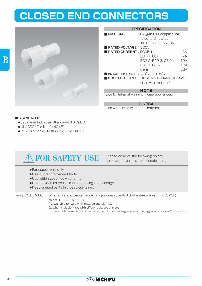
■MATERIAL :Oxygen free copper tube. (electro-tin-plated) INSULATOR:NYLON■RATEDVOLTAGE:300V■RATEDCURRENT:EC05-1 3A EC1-1, CE-1, 7A EC2-2, EC2-3, CE-2, 12A EC3-1, CE-5, 17A CE-8 23A■ INSULATORTEMPERATURE:-40℃〜 +105℃■ FLAMERETARDANCE:UL94V2(Available UL94V0 upon your request)
CLOSED END CONNECTORSSPECIFICATION
■STANDARDS● Japanese Industrial Standards JIS C2807● UL486C(File No. E44245)● CSA C22.2 No.188 (File No. LR-28418)
NOTE
UL/CSA
Use for internal wiring of home appliances.
Use with listed wire combinations.
FOR SAFETY USE
Wire range and performance ratings comply with JIS standards wire(IV, KIV, VSF)APPLICABLE WIREas per JIS C 2807:2003;-1. Available for wire with max. strand dia. 1.0mm2. When multiple wires with different dia. are crimped, the smaller wire dia. must be more than 1/2 of the bigger wire, if the bigger wire is over 0.5mm dia.
B

67
BCE 1
CE 2
CE 5
CE 8
2.4
3.0
3.9
4.8
6.5
8.0
10.5
12.0
18.0
21.0
28.0
24.5
6.2
7.3
7.2
8.2
8.8
9.6
10.8
11.9
0.5~1.75
1.0~3.0
2.5~6.0
4.0~9.0
22-16
16-14
12-10
8
EL R mm2 AWGφDφd
'
'
'
'
NH 38 Nylon Milky White 500
PART NUMBERDIMENSIONS mm WIRE RANGE
INS COLORTOOL No.
Hand PneumaticSTD
QTY/BOX
Pleasesee the tooling pagefor applicable dieswith NA10・NA 3.
NOTE 1) ':JIS・UL・CSA
2) For UL/CSA, see tool selection.(Page 139)
1,000(100×10)
(100×5)
JIS C 2807
WIRE COMBINATIONS CHART(UL/CSA)
See page 2
CLOSED END CONNECTORS(CE TYPE)
LRE
φD
φd
0057
LRE
φD
φd
0057
CE 1
CE 2
CE 5
CE 8
1~30~20~11~31~21~2
13~72~61~52~61~51~41~51~41~21~41~27~96~85~77~85~73~56~84~61~55~81~61~52~71~6
1~21~2
11~20~1
11
2~41~31~31~40~30~21~31~2
11~2
15~94~84~74~83~72~64~71~51~33~41~31~21~61~4
7~126~115~104~93~82~7
7~115~104~92~81~6
7~115~101~71~6
7~101~81~51~81~21~5
1111
1
1~21~21~21~21~21~21~20~1
01~2
13~63~63~53~52~42~33~52~41~32~41~21~21~41~25~84~74~73~62~52~45~84~73~62~51~44~82~61~41~33~71~41~21~51~21~4
1
1
1~211
1~21111
1
2~32~3
22~31~21~22~31~21~21~20~1
01~2
13~42~42~41~31~31~23~42~42~31~21~23~42~31~20~12~41~21~21~2
11~3
11111
1
211
1~21~21~21~21~2
11~2
1
1~21
2~32~3
21~21~21
2~32
1~21~2
12
1~21~21~21~20~1
0111
1111111111
1
1~21~2
1111
1~21~2
111111111
101
1
1
1111111111
1
1
1
12312111231231231112312312312311123456123451234123121
PART NUMBER
■See next page how to use this chart.WIRE RANGE
mm2WIRE A
mm2(AWG)WIRE B mm2(AWG)
0.5~1.75
1.0~3.0
2.5~6.0
4.0~9.0
0.3(22)
0.5(20)
0.75(18)1.25(16)
0.3(22)
0.5(20)
0.75(18)
1.25(16)2.0(14)
0.3(22)
0.5(20)
0.75(18)
1.25(16)
2.0(14)3.5(12)
0.5(20)
0.75(18)
1.25(16)
2.0(14)
3.5(12)
5.5(10)
0.3(22) 0.5(20) 0.75(18) 1.25(16) 2.0(14) 3.5(12) 5.5(10)PCS
68
PARTNUMBER mm2(AWG) PCS 0.5(20) 0.75(18) 1.25(16) 2.0(14) 3.5(12)
WIRE A WIRE B mm2(AWG)mm2
WIRE COMBINATION
EC 2-2 1.0~2.63
EC 2-3 1.0~3.0
EC 3-1 2.63~6.64
1~3
1~3
1~2
0~2
1~3
1~3
1~3
1~2
0~2
5
4~5
3~4
2~4
1~3
4
3~4
1~3
1~2
1
1
1
1~3
1~2
1~2
1
1~2
3~5
3~4
2~4
1~3
1~2
3~4
2~3
1~2
1
1
1
1
1~2
1~2
1
1
1
2~3
2~3
1~2
1~2
1
2
1~2
0~1
1
1
1
2
1~2
1
1
1
1
1
1
1
1
1
1
1
WIRE COMBINATIONS CHART(UL/CSA)
1
2
1
2
1
2
0.5(20)0.75(18)1.25(16)0.5(20)0.5(20)0.75(18)1.25(16)2.0(14)0.5(20)0.5(20)0.75(18)1.25(16)2.0(14)3.5(12)0.5(20)0.75(18)1.25(16)
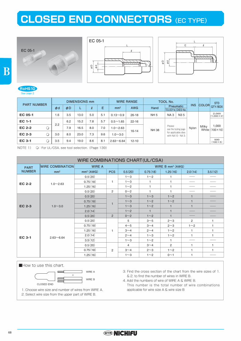
EC 05-1
EC 1-1
EC 2-2
EC 2-3
EC 3-1
1.6
3.0
3.5
3.5
6.2
7.9
8.0
9.4
13.0
15.2
16.5
23.0
19.0
5.0
7.8
8.0
7.3
8.6
5.1
5.7
7.0
9.6
8.1
0.13~0.9
0.5~1.65
1.0~2.63
1.0~3.0
2.63~6.64
26-18
22-16
12-10
16-14
EL R mm2 AWGφDφd
£
£
£
NH 5 NA 3 N3 5
TOOL BODY No. DIES No.
Nylon Milky White
1,000(100×10)
500(100×5)
2,000(1,000×2)
2.2
NH 38
PART NUMBERDIMENSIONS mm WIRE RANGE
INS COLORTOOL No.
Hand PneumaticSTD
QTY/BOX
Pleasesee the tooling pagefor applicable dieswith NA10・NA 3.
NOTE 1) £:For UL/CSA, see tool selection.(Page 139)
RE
φD
φd
L
58-2
R
φD
φd
L
58-1
CLOSED END CONNECTORS(EC TYPE)
EC 05-1
See page 2
1. Choose wire size and number of wires from WIRE A.2. Select wire size from the upper part of WIRE B.
■How to use this chart.3. Find the cross section of the chart from the wire sizes of 1.
& 2. to find the number of wires in WIRE B.4. Add the numbers of wire of WIRE A & WIRE B. This number is the total number of wire combinations
applicable for wire size A & wire size B
WIRE A+
CLOSED END
WIRE B
B
EC 05-1