Closed-cycle gas flow system for cooling of high T, d.c ...
8
UTTERWORTH EINEMANN Cryogenics 35 (1995) 109-l 16 0 1995 Elsevier Science Limited Printed in Great Britain. All rights reserved 001 l-2275/95/$1O.Ofl Closed-cycle gas flow system for cooling of high T, d.c. SQUID magnetometers P.J. van den Bosch, H.J. Holland, H.J.M. ter Brake and H. Rogalla University of Twente, Department of Applied Physics, Low Temperatures Division, PO Box 217,750O AE Enschede, The Netherlands Received 12 July 1994 A high T, d.c. SQUID based magnetometer for magnetocardiography is currently under development at the University of Twente. Since such a magnetometer should be sim- ple to use, the cooling of the system can be realized most practically by means of a cryocooler. A closed-cycle gas flow cooling system incorporating such a cooler has been designed, constructed and tested. The aimed resolution of the magnetometer is 0.1 pT HZ-‘/~. The required operating temperature for the SQUIDS is 30 to about 77 K with a stability of 2 x 10“ K HZ-‘/*. After a cool-down time of l-2 h, a stationary cooling power of at least 0.2 W is required. In the design, helium gas is cooled by a Leybold Heraeus RG 210 cryocooler, transported through a gas line, and subsequently passed through a heat exchanger on which SQUIDS can be installed. The lowest obtainable SQUID heat exchanger temperature is 31+2 K. This can be reached in roughly 2-3 h with an optimal mass flow with respect to the cooling power of 6 x 1O-6 kg s-l. At this mass flow the cooling power at the SQUID heat exchanger is 0.2 W at 42 K and roughly 1.2 W at 77 K. A temperature stability of 0.05 K was measured at a SQUID heat exchanger temperature of 54 K and a mass flow of 3 x 10e5 kg s-l. The experience gained with this large cooling system will be used in the design of a smaller configur- ation cooling system, incorporating miniature Stirling cryocoolers. In this paper the design and the construction of the present closed-cycle system are described and test results are presented. Keywords: high T, d.c. SQUID magnetometer; closed-cycle gas flow cooling; heat transfer Superconducting quantum interference devices (SQUIDS) are the most sensitive magnetic flux-to-voltage converting sensors. This has opened the way for biomagnetic research by means of multichannel low T, d.c. SQUID based mag- netometer systems’-3. These systems are usually cooled by liquid helium and operated in magnetically shielded rooms to obtain an extremely low-noise environment. However, they are expensive, require helium refills and cannot be transported in a simple manner. Since high T, d.c. SQUIDS can operate at much higher temperatures (up to liquid nitro- gen temperature)4-7, small scale cryocoolers8 can be applied to cool a simple to use high T, d.c. SQUID based magnetometer system. Reliable, small scale, turn-key cryo- coolers for infrared applications are available’. In this paper, a closed-cycle gas flow system for cooling a high T, d.c. SQUID based magnetometer for heart measurements is described. Although the cooling power of the Leybold Heraeus RG 210 cryocooler in the present system is over- sized, experience with this large scale system can be used in the design of smaller systems, based on one or more miniature Stirling cryocoolers. Topics such as magnetic noise suppression via active or passive compensation and elimination of cooler vibrations are under study, but beyond the scope of this paper. In the following section of this paper, the requirements for a closed-cycle gas flow system for cooling a high T, d.c. SQUID based magnetometer are considered. After that, the design aspects of our system are described. Experimen- tal results are presented and discussed in the last section. Requirements The aim of the high Yf’, d.c. SQUID magnetometer used in this study is to measure adult human heart signals with a resolution of 0.1 pT Hz-“* in a bandwidth of 0.1-40 Hz in the pick-up coil. This value is sufficient for heart signal measurements and can be achieved using recently fabri- cated high T, d.c. SQUIDS 4,5. The technical requirements which are important for the magnetometer cooling system are listed in Table I. Cryogenics 1995 Volume 35, Number 2 109
Transcript of Closed-cycle gas flow system for cooling of high T, d.c ...
UTTERWORTH EINEMANN
Cryogenics 35 (1995) 109-l 16
0 1995 Elsevier Science Limited
Printed in Great Britain. All rights reserved
001 l-2275/95/$1O.Ofl
Closed-cycle gas flow system for cooling of high T, d.c. SQUID magnetometers P.J. van den Bosch, H.J. Holland, H.J.M. ter Brake and H. Rogalla
University of Twente, Department of Applied Physics, Low Temperatures Division, PO Box 217,750O AE Enschede, The Netherlands
Received 12 July 1994
A high T, d.c. SQUID based magnetometer for magnetocardiography is currently under development at the University of Twente. Since such a magnetometer should be sim- ple to use, the cooling of the system can be realized most practically by means of a cryocooler. A closed-cycle gas flow cooling system incorporating such a cooler has been designed, constructed and tested. The aimed resolution of the magnetometer is 0.1 pT HZ-‘/~. The required operating temperature for the SQUIDS is 30 to about 77 K with a stability of 2 x 10“ K HZ-‘/*. After a cool-down time of l-2 h, a stationary cooling power of at least 0.2 W is required. In the design, helium gas is cooled by a Leybold Heraeus RG 210 cryocooler, transported through a gas line, and subsequently passed through a heat exchanger on which SQUIDS can be installed. The lowest obtainable SQUID heat exchanger temperature is 31+2 K. This can be reached in roughly 2-3 h with an optimal mass flow with respect to the cooling power of 6 x 1O-6 kg s-l. At this mass flow the cooling power at the SQUID heat exchanger is 0.2 W at 42 K and roughly 1.2 W at 77 K. A temperature stability of 0.05 K was measured at a SQUID heat exchanger temperature of 54 K and a mass flow of 3 x 10e5 kg s-l. The experience gained with this large cooling system will be used in the design of a smaller configur- ation cooling system, incorporating miniature Stirling cryocoolers. In this paper the design and the construction of the present closed-cycle system are described and test results are presented.
Keywords: high T, d.c. SQUID magnetometer; closed-cycle gas flow cooling; heat transfer
Superconducting quantum interference devices (SQUIDS) are the most sensitive magnetic flux-to-voltage converting sensors. This has opened the way for biomagnetic research by means of multichannel low T, d.c. SQUID based mag- netometer systems’-3. These systems are usually cooled by liquid helium and operated in magnetically shielded rooms to obtain an extremely low-noise environment. However, they are expensive, require helium refills and cannot be transported in a simple manner. Since high T, d.c. SQUIDS can operate at much higher temperatures (up to liquid nitro- gen temperature)4-7, small scale cryocoolers8 can be applied to cool a simple to use high T, d.c. SQUID based magnetometer system. Reliable, small scale, turn-key cryo- coolers for infrared applications are available’. In this paper, a closed-cycle gas flow system for cooling a high T, d.c. SQUID based magnetometer for heart measurements is described. Although the cooling power of the Leybold Heraeus RG 210 cryocooler in the present system is over- sized, experience with this large scale system can be used in the design of smaller systems, based on one or more miniature Stirling cryocoolers. Topics such as magnetic noise suppression via active or passive compensation and
elimination of cooler vibrations are under study, but beyond the scope of this paper.
In the following section of this paper, the requirements for a closed-cycle gas flow system for cooling a high T, d.c. SQUID based magnetometer are considered. After that, the design aspects of our system are described. Experimen- tal results are presented and discussed in the last section.
Requirements
The aim of the high Yf’, d.c. SQUID magnetometer used in this study is to measure adult human heart signals with a resolution of 0.1 pT Hz-“* in a bandwidth of 0.1-40 Hz in the pick-up coil. This value is sufficient for heart signal measurements and can be achieved using recently fabri- cated high T, d.c. SQUIDS 4,5. The technical requirements which are important for the magnetometer cooling system are listed in Table I.
Cryogenics 1995 Volume 35, Number 2 109

Closed-cycle gas flow cooling system: P.J. van den Bosch et al.
Table 1 Required features of high T, dc. SQUID magnet- ometer cooling system with an aimed resolution of 0.1 pT Hz-‘/*
Parameter Require- Comment ment
Typical operating temperature (K) 30-77 1 Temperature stability (K HZ-‘? <2x10⁴ 2
Mass to be cooled (kg) 0.002 3 Cooling power (WI 2 0.2 3 Cool-down time (h) l-2 3
Mean time between: Routine maintenance (yr) > 0.5 4 Failure (yr) >l-2 4
Magnetic interference (T HZ-‘? 5 IO-‘3 5 Vibration level (degree Hz-‘? 5 IO-’ 6
Comments on Table 1
The maximum operating temperature of the d.c. SQUID is limited by the intrinsic noise of presently available high T, d.c. SQUIDs4-’ relative to the desired resol- ution. Small scale cryocoolers make operation at tem- peratures down to ~30 K possible. One may expect that the requirement for temperature stability is related to the thermal fluctuations in the criti- cal currents of the Josephson junctions in the d.c. SQUID, which, at low temperatures, are the main source of intrinsic noise in a high T, d.c. SQUID. How- ever, modulation techniques can be applied to eliminate the influence of these critical current fluctuations”. Therefore, a more stringent requirement results from the thermal expansion of the magnetometer sensing coil. Because of the small thickness of the sensing coil, the thermal expansion is mainly determined by the SrTiO, substrate (~5 x 10e6 K-l at 50 K”). The required tem- perature stability is determined by calculating the tem- perature effect on the sensing coil in the earth’s mag- netic field (EMF) in the worst case that the EMF is perpendicular to the area of the sensing coil. A compen- sation coil may relax the required temperature stability in the EMF with a factor equivalent to the compensation factor for d.c. magnetic fields of the coil; a factor of roughly lo3 has been reported’*. A d.c. SQUID is nearly non-dissipative. Therefore, the cooling power is used mainly to compensate the station- ary thermal load, which is predominantly caused by heat conduction from the supporting material and the leads to the sensor. Because the heat capacity of the sensor is small compared to the capacity of the rest of the system, the latter will determine the cool-down time. The mean times between failure and routine mainte- nance are based on the situation outside cryogenic lab- oratories. Depending on the uniformity of the magnetic noise due to the cryogenic system, gradiometer-type construction of the sensing coil can increase the acceptable noise level by a factor of =103, a value which is determined by the common mode rejection ratio (CMRR)13. The largest noise contribution arises from axial tiltings of the sensing coil in an external field. A sensing coil vibrating in the EMF results in a noise contribution of
~10~ T per degree. Again, a gradiometer-type con- figuration may incease the acceptable mechanical vibration level in the EMF by a factor equivalent to the CMRR (roughly 103). Moreover, a compensation coil as mentioned in comment 2 may also relax the require- ment for the vibration level.
Design
Figure 1 schematically shows our cooling system. Helium gas is forced to flow in a closed cycle by means of a gas- flow pump and is cooled by an LH-RG 210 cryocooler. The cold gas is transported through a coaxial gas line, and cools a d.c. SQUID via a heat exchanger. (Hereafter a heat exchanger is denoted as hx.) The return gas is used to ther- mally insulate the supply gas. Because the gas-flow pump operates at room temperature, a counterflow heat exchanger (henceforth denoted as cfhx) has been incorporated. The whole closed-cycle system is vacuum insulated. A photo- graph of the cooling system is presented in Figure 2. The separate elements of the system will be considered in the following sections, and are described in more detail else- wherei4.
Gas flow controller
The helium gas flow in the closed-cycle system is con- trolled by a gas flow controller, which consists of two paral- lel mass flow controllers for two ranges: 4 x lO_‘- 4 x 10m6 kg s-i and 4 x 10e6--4 x 10m5 kg s-i. The gas is pumped with an oil-free diaphragm pump to prevent oil pollution of the helium gas in the closed-cycle system. This pump is shunted by an adjustable valve to control the press- ure in order to prevent overheating of the pump. The mass flow can be blocked with a valve in the flush and fill section of the gas flow controller. By means of this section the system can be cleaned and (re)filled. Pressure meters are installed at the inlet and the outlet sides of the controller. Finally, two buffer volumes ( 1120 and 160 cm3) have been incorporated, which reduce the filling pressure of the sys- tem. A small overpressure of ~0.1 bar* during cool-down is chosen in order to prevent pollution of the gas circuit via small leaks. The buffers also reduce the gas flow fluc- tuations caused by the pump, which may disturb the mass flow measurement.
The temperatures in the cooling system depend on both the mass flow riz of the helium gas and the refrigerating characteristics of the cryocooler. The maximum mass flow depends directly on the pump characteristic (pressure drop versus rh). It also depends indirectly on the temperature T, since the pressure drop in the closed-cycle system Aps is related to T. Based on the cryocooler refrigerating power, the measured pump characteristic and an estimate of Ap,, a maximum mass flow lj2,, of 2 x lo-’ kg s-l at the start of a cool-down of the system seems possible and suf- ficient14. The estimate of Aps is based on a laminar, fric- tionless helium gas flow at room temperature through a transfer line with a hydraulic diameter of 1.6 mm and a length of 10 m. At lower T, Aps decreases.
At %,, the cool-down time of the complete system is,
* 1 bar = IO5 N me2
110 Cryogenics 1995 Volume 35, Number 2

gas flow controller
mfc
cryocooler unit I I
gas SQUID unit line
Closed-cycle gas flow cooling system: P.J. van den Bosch et al.
t
control unit
mfc hl h2
Figure 1 Scheme of the designed closed-cycle gas flow system. In this system the temperatures are measured at the first stage of the cryocooler (denoted by CHl), at the second stage of the cryocooler (CH2), at the gas supply line inlet (GLi), at the SQUID unit inlet (SQi), at the SQUID heat exchanger (SO), at the SQUID unit outlet (SQo), at the cold inlet and cold outlet of the counter-flow heat exchanger (CFci and CFco, respectively), and finally at the warm inlet and warm outlet of the counterflow heat exchanger (CFwi and CFwo, respectively). The mass flow controller is indicated by mfc, the counter flow heat exchanger by cfhx, a buffer and a heater by b and h, respectively, and vacuum by+
Figure 2 Photograph of the closed-cycle gas flow cooling system
for a large part, determined by the heat capacity in the cryo- cooler unit (cryocooler plus copper hxs). At this rate of flow, a cool-down time of -2 h is expected. Cooling the cryocooler plus the hxs separately would take -1 h (reference 15).
Cryocooler unit
The cryocooler unit utilizes an LH-RG 210 cryocooler and a cfhx, both placed in a vacuum environment. The Gifford- McMahon type cryocooler consists of a compressor and a two-stage cold head. It has a refrigeration capacity of 14 W at 80 K on the first stage combined with 2 W at 20 K on
the second stage15. Two copper hxs are mounted on the two stages and are connected by a flexible spiral-shaped stain- less steel tube (inner and outer diameters of 1.6 and 2 mm, respectively). These hxs are fabricated from copper blocks in which grooves have been machined to serve as gas chan- nels. The cross-sectional area of these square channels is -2.3 mm2 and the lengths of the first and second stage hxs are 0.7 and 1 m, respectively. The hx on the second stage is surrounded by a copper radiation shield, which has been connected to the first stage. The cfhx keeps the temperature difference between the environment and the first cold head stage more or less constant. It consists of two coaxial stain- less steel tubes with a length of 1 m. The inner tube, which
Cryogenics 1995 Volume 35, Number 2 111

Closed-cycle gas flow cooling system: P.J. van den Bosch et al.
Figure 3 Schematic cross-section of the gas line
is connected to the return gas transfer line, has inner and outer diameters of 1.6 and 2 mm, respectively. The outer tube has diameters of 3 and 4 mm, respectively. Both the inner side of the cryocooler unit and the copper radiation shield are covered by multilayer insulation (MLI).
Gas line unit
Measurements of the magnetic interference originating from the crycooler were performed to determine the required distance between the cryocooler and the SQUID. A large magnetic noise contribution (> 0.1 pT Hz-“*) from the cryocooler in the frequency bandwidth relevant to cardiomagnetometry (0.1-40 Hz) should be avoided. Because the compressor can be located at =2 m from the cold head, the main noise contribution at the SQUID appeared to be due to the cold head. Based on the magnetic noise measurements, a separation of 2.5 m between the cold head and the sensor was chosen14. This distance may be reduced if the cold head is shielded with mu-metal. How- ever, problems might arise with respect to vibrations of the magnetic shield.
The cold helium gas is transported through the 2.5 m long coaxial gas transfer line, in which both the supply and return lines are combined (see Figure 3). Because a flexible coaxial line is expensive and, as expected, not necessary in future small scale configurations, the transfer line is fabri- cated in a rigid manner. All tubes are made of stainless steel. The inner (and outer) diameters of the four tubes are, respectively, 1.6 (2), 3 (4), 5 (6) and 7 (8) mm. The cold gas from the cryocooler unit flows through the inner tube, which is thermally insulated by a vacuum space around this tube and the return gas line. The return gas line is only insulated by a vacuum space. Nylon wire is used as spacer material in both vacuum spaces to avoid direct contact between adjacent lines. At the sensor end of the gas line, the supply and return lines split into two separate lines (see Figure 4~). The stainless steel transfer lines are fixed with
radiation shield
SQUID heat exchanger
JlOmm 1Omm
Figure4 Schematic views of (a) the SQUID unit and (b) the spiral channel structure of the heat exchangers (the spiral of the radiation shield is depicted)
nylon wires to avoid damage to the SQUID unit due to thermal shrinkage and expansion of the gas line elements.
SQUID unit
The SQUID unit is shown schematically in Figure 4~. The cold gas from the gas line unit flows directly into the lower hx. In this way, a dc. SQUID mounted on the bottom side of this SQUID hx can be cooled. The helium gas returns to the gas line unit via a second hx which serves as a radi- ation shield.
To reduce the thermal noise and to prevent magnetic noise from metals in the vicinity of the d.c. SQUID, the SQUID unit was made of glass-epoxy Gl 1 (HGW 2372.4)i4. This material is easily machinable with standard tools and we have considerable cryogenic experience of it. At the entrance of the SQUID unit the stainless steel trans- fer lines have been glued to two small glass-epoxy tubes. The small tubes were glued to the hxs at the bottom and are wrapped in MLI. The tubes have inner and outer diameters of 2 and 5 mm, respectively, with a length of ~0.12 m.
The SQUID hx and the radiation shield have a flat spiral channel structure (see Figure 4b) to limit the temperature gradient over the plates. The plates are 3.9 mm thick and have diameters of 5 and 7 cm, respectively. The machined channels are 2 mm wide, 1.5 mm deep and have lengths of 0.6 and 0.9 m. Glass-epoxy spacers (3 mm long) have been glued between the SQUID hx and the radiation shield, and also between the radiation shield and the top plate of the SQUID box. The hxs are situated in a vacuum environment. At the bottom side of the SQUID hx several (=20) layers of ML1 have been placed.
Two heaters made of high-ohmic wire are fixed in this unit. The first one has been wound around the stainless steel tube at the top of the SQUID unit, just before the transition of the supply gas line to the glass-epoxy tube. This heater can be used to control the temperature stability at the SQUID hx. For measuring the cooling power at the SQUID hx, a second heater was fixed in the middle of the bottom side of this hx.
Control unit
The temperatures in the system are measured with Lake Shore DT-470/471 silicon temperature diodes. The esti- mated error in T is 1.4 K for T < 100 K and (0.6 + O.OOSl? K for 100 K < T < 300 K. The temperatures at the first and second stage of the cold head are measured by diodes that have been installed in the copper hxs mounted on these stages. In the SQUID unit the diode has been fixed to the plate by aluminium tape. All the other diodes are fixed to the gas transfer line with an aluminium oxide holder to establish good thermal contact with no electrical leakage currents. The aluminium oxide holder consists of two pieces, which are pressed together by a small aluminium tube or, in the case of the diodes for measuring the inlet and outlet temperature of the SQUID unit, by aluminium tape. Apiezon grease is used to increase thermal contact between the different parts. The measured temperatures as well as the measured mass flow are automatically and on- line registered by the control unit. The mass flow is con- trolled by two mass flow controllers. The estimated error in riz is l-2%. Both heaters in the SQUID unit can be fed with separate sources from the control unit.
112 Cryogenics 1995 Volume 35, Number 2

Closed-cycle gas flow cooling system: P.J. van den Bosch et al.
Table 2 Estimated pressure and temperature drops, Ap and AT, respectively, for system units at initial and final thermodynamic stat- es
Unit Volume (IO” m3)
rb = 2 x lO-5 kg s-’
Ap (105Pa)
rh = 1 x lO-6 kg s-’ (steady state)
Ap (IO2 Pa) AT(K)
Gas flow controller 1350 -0.001 -0.04 0 Counterflow hx-supply 6 -0.27 -3.7 -(50-100) Cold head: first and second stage 4 -0.29 -0.4 -200 Supply gas line 6 -0.43 -0.5 20 SQUID unit 3 -0.35 -0.4 15 Return line gas 21 -0.29 -0.7 165 Counterflow hx-return 3 -0.22 -1.9 50-100 Total system (without pump) 1393 -1.85 -7.6
Estimated pressure and temperature drops
Based on the hydraulic diameters in the system, the charac- teristics of the cooler and the pump, and some assumptions on conductive and radiative heat flows, the temperature and pressure drops, AT and Ap, have been evaluated. In Table 2 the Ap values are presented for the warm start-up situation, whereas for the cold steady state both Ap and AT values are given. The higher riz is supposed to be used at the start of cool-down, resulting in the highest Ap values. The lower riz will be used in the cold steady state.
Results
Figure 5 shows a typical cool-down recorded by the 10 temperature diodes in the system. It was measured at a con- stant ti of 1.4 x 10e5 kg s-’ and it shows a stationary SQUID temperature TsQ of 33 K after 22 h. This Tso was
measured in the centre of the bottom side of the SQUID hx. The figure shows cool-down of the system, starting from the first stage temperature of the cryocooler (TCH,), followed by the second stage temperature of the cryocooler (TCH2), the gas supply line inlet temperature (TGLi), the SQUID inlet temperature (Tsai), TsQ and the SQUID outlet temperature (Tsoo). Later on the &x-cold in and -cold out temperatures (TcFci and TcFco, respectively) follow. As expected the cfhx-warm in and -warm out temperatures
(TcFwi and TcF~~, respectively) remain almost constant at room temperature. TCHl cools down exponentially for about 30 min. Subsequently, when the cfhx becomes effective, T CH, decreases linearly with time for more than 30 min,
300
250
200
150
100
50
CFCI CFco
0 50 100 150 200 250
Time (min.)
Figure 5 Cool-down recorded by the 10 temperature diodes in the system at constant rh = 1.4 x lO-5 kg s-‘. The different pos- itions in the system are denoted by abbreviations as defined in the caption to Figure 7
followed by a second exponential cool-down tail. TCH2 appears to cool down continuously to much lower tempera- tures in an exponential way.
After almost 1 h, TcFci and TCFco start to cool down shar- ply, showing that the system including the total gas line has been cooled down up to the cfhx. This also indicates good thermal insulation between the supply and return gas line. In general, at constant cooling power the time between two sharp temperature decreases as seen in Figure 5 can be considered an indication of the heat capacity of the material between the two temperature-measuring points. The mass of the material between the positions of the diodes measur- ing TGLi and Tsai is roughly a factor of 10 smaller than the mass of the material between the positions of the diodes measuring Tsao and TCFci. As expected, the figure shows that the ratio of the times between the sharp drops of TcLi and T,,i, and Ts% and TC+i is also roughly 10.
The temperature stability was measured with the diode =3 cm from the centre of the bottom side of the SQUID hx (T’,,). Figure 6 shows the stability of T’,, as a function of time. In this experiment, ti was kept constant at 2 x 10m5 kg s’ and T’,, was 40 K but not completely stabilized. Inset A in this figure shows a temperature stability of
0.5
0
z 51 -0.5
%I
-1.0
0 5 IO I I / I
0 10 20 30 40
Time (min.)
Figure 6 Temperature stability of Tsa (denoted by ATso) as a function of time measured on the bottom side of the SQUID heat exchanger at m = 2 x lO-5 kg s-l and T’S0 = 40 K (not stabilized). Inset A was measured at ti = 3 x 10” kg s-l and Tsa = 54 K (steady state)
Cryogenics 1995 Volume 35, Number 2 113
Closed-cycle gas flow cooling system: P. J. van den Bosch et al.
~0.05 K measured for ~12 min at a flow of 3 x 10e5 kg s-l and a steady state T’,, of 54 K. The long term stability is limited by small, frequently occurring temperature dips in T’,, (maximum 0.4 K, duration 3-4 min, approximately once per 18 min; see inset B). Such dips are also observed in T,--, and TCHZ, although the maximum depth of the dips in Tcnl is smaller. These dips are most probably caused by temporary blockings of the bypass from the oil separator to the pump in the compressor of the cryocooler due to oil droplets that flow back through the bypass to the pump, causing pressure rises and consequently a lower tempera- ture at the cryocooler stages. The drift effect in the figure (estimated at roughly -0.8 K h-l) was mainly due to the fact that the system was not completely stabilized. The small dips and their delayed influence might also partly have determined the drift.
The long term variations do not have to be reduced because they lie outside the frequency range of interest. The temperature fluctuation of 0.05 K at the SQUID hx, however, is relevant and is roughly a factor 40 higher than the required temperature stability. A temperature control system via regulation of riz is under investigation. Also the requirement with respect to temperature stability can be relaxed when the EMF is compensated by means of a coil.
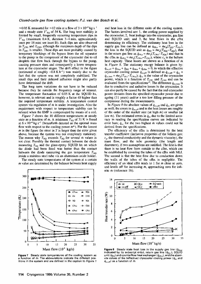
and heat loss in the different units of the cooling system. The factors involved are: 1, the cooling power supplied by the cryocooler; 2, heat leakage into the cryocooler, gas line and SQUID unit; and 3, the heat flows in the cfbx determining its efficiency. The stationary heat loss in the supply gas line can be defined as 4oLs = rizcp(TsQi-TGLi), the loss in the SQUID unit as &o = tfq,(T,,-T,,,), that in the return gas line as (iGLr = kcp(T~,i-T~,) and that in the cfhx as &ax = rizcr( TcFco-TcFci), where cr is the helium heat capacity. These losses are shown as a function of ti in Figure 8. The stationary energy balance is given by: 4,c.eff + QcLs + Qso + QGLr + Qcfhx = 0, in which the effective cryocooler cooling power 4CC,eff is defined as c&,,~~~ = & + &C,lOSS = +rcr(ToLi-TcFco); il,, is the value of the cryocooler power, which is a function of TCHl and TCH2 and can be evaluated from the specifications15. The difference g,,,,,,,, is due to conductive and radiative losses in the cryocooler. It can also partly be caused by the fact that the real cryocooler power deviates from the specified cryocooler power due to ageing (11 years) and/or a too low filling pressure of the compressor during the measurements.
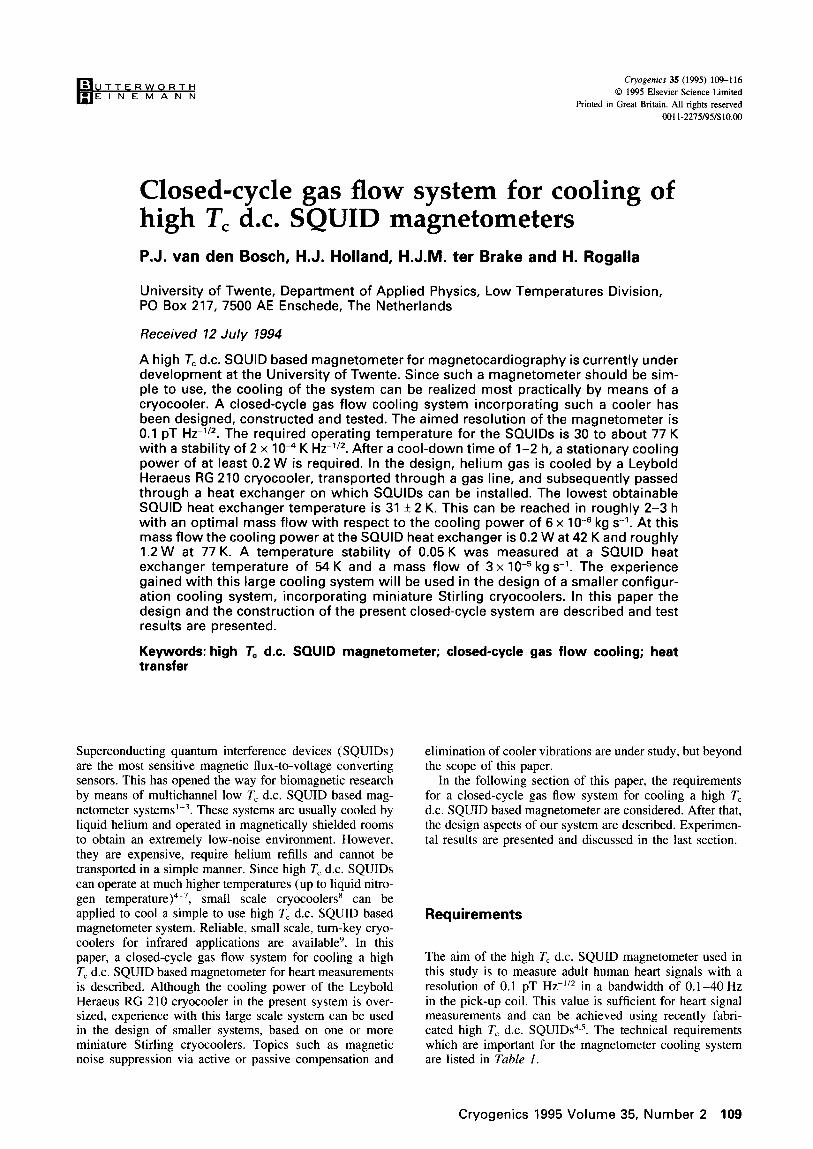
Figure 7 shows the 10 different temperatures at steady state as a function of rit. A minimum TsQ of 31 K is found at 6 x lo6 kg s-’ (henceforth denoted as the optimal mass flow with respect to the cooling power Cr*). For the lowest ti in the figure the error in T is larger than the error given above, because the system was not completely stationary. The reason why Tsoi exceeds Tso for several Cr values is not clear. Possibly the thermal contact between the diode measuring Tso and the glass-epoxy SQUID hx on which the diode had been fixed was better than the contact between the diode measuring the gas temperature Tsai inside a stainless steel tube via an aluminium oxide holder.
In Figure 8 the absolute values of &.ff and & are given as well; the errors in Q_rf and in the heat losses are roughly of the order of the marker size (at high rit) or smaller (at low ti). The estimated errors in QC1: due to the limited accu- racy in reading the specification curves are indicated by error bars; & for the two highest liz values could not be derived from the specifications.
The steady state temperatures of the system at a certain ti value are determined by the balance between heat supply
The efficiency of the cfhx is determined by the heat transfer coefficient (inclusive properties of the helium gas: cp, the thermal conductivity and the dynamic viscosity), the mass flow, and the tube geometry (the length and diameters), if two assumptions are satisfied. The first is that there is no heat flow from outside to the cfbx, which can be established by covering the tubes of the cfhx with MLI. The second is that the heat flow due to conduction down the walls of the tubes of the cfhx is negligible. The efficiency of an ideal cfhx tends to 1 for riz close to zero, and levels off for increasing riz, approaching zero for infi- nite ri2 (reference 16).
300
250
* CFwo * SQO
0 Gli -V- CH2
Q SQ -X- SQi
-A- CFco -t CHI
* CFwi -T- CFci
0 5 IO 15 20 25 30 35
Mass flow (lo’” kg/s)
Figure 7 Steady state temperatures of the cooling system as a function of rh. The abbreviations indicate the different pos- itions in the system and are defined in the caption to Figure 7
-o- cc a- cc,eff
j<-GLS -v- SQ unit -A- GLr -o- c&x
/ /
/
0 5 10 IS 20 25 30
Mass flow (10” kg/s)
Figure8 Steady state heat loss in the supply gas line (4GL., indicated by its subscript only), return gas line (4GL,), SQUID unit (4*J and counterflow heat exchanger (4,+J, and the absol- ute values of the (effective) cryocooler cooling power (4,, and 4_+J as a function of rh
114 Cryogenics 1995 Volume 35, Number 2
Closed-cycle gas flow cooling system: P.J. van den Bosch et al.
l.OO I 0.98 -
n I 0.96
mm -
ox .s 0.94 : -
4 n n
w 0.92 -
.rn
0.90 -
0.88 I, 0 5 10 15 20 25 30 35
Mass flow ( 10v6 kg/s )
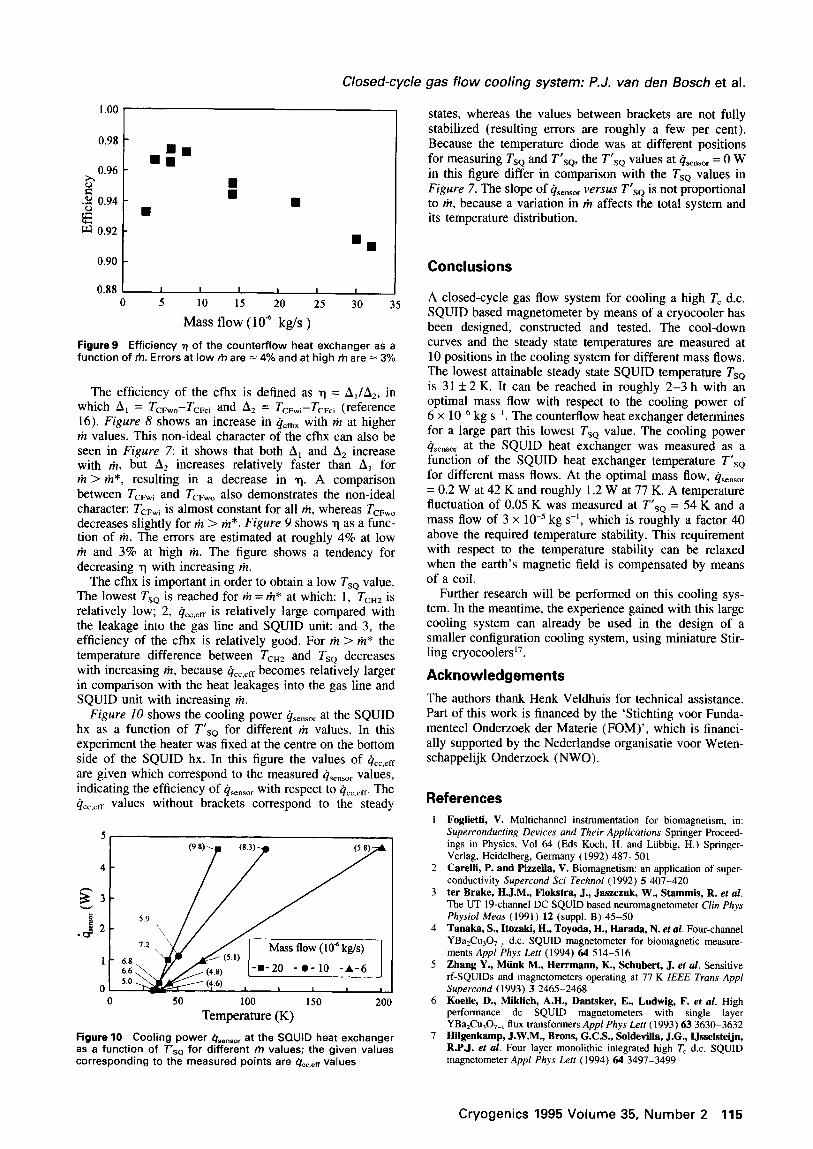
Figure9 Efficiency r) of the counterflow heat exchanger as a function of rh. Errors at low rb are = 4% and at high rh are i= 3%
The efficiency of the cfhx is defined as r) = A,/A2, in which A, = TCFwo-TCFci and A2 = TCFwi-TCFci (reference 16). Figure 8 shows an increase in QCfhX with ti at higher riz values. This non-ideal character of the cfhx can also be seen in Figure 7: it shows that both A, and A2 increase with ti, but A2 increases relatively faster than A, for ti > ril*, resulting in a decrease in q. A comparison between TcFwi and TCFwo also demonstrates the non-ideal character: TCFwi is almost constant for all riz, whereas TCFwo decreases slightly for riz > ti*. Figure 9 shows -q as a func- tion of ti. The errors are estimated at roughly 4% at low ti and 3% at high liz. The figure shows a tendency for decreasing q with increasing riz.
The cfhx is important in order to obtain a low Tso value. The lowest TsQ is reached for ti = rit* at which: 1, TCHZ is relatively low; 2, c&,,,~~ is relatively large compared with the leakage into the gas line and SQUID unit; and 3, the efficiency of the cfbx is relatively good. For rit > ri2* the temperature difference between TCH2 and Tso decreases with increasing riz, because &eff becomes relatively larger in comparison with the heat leakages into the gas line and SQUID unit with increasing riz.
Figure 10 shows the cooling power gSenSOr at the SQUID hx as a function of T’,, for different ti values. In this experiment the heater was fixed at the centre on the bottom side of the SQUID hx. In this figure the values of c&~ are given which correspond to the measured Qsensor values, indicating the efficiency of &nsOI with respect to c&~. The qcC,eff values without brackets correspond to the steady
50 100 150 200
Temperature (K)
Figure 10 Cooling power &,,.,r at the SQUID heat exchanger as a function of Tsa for different m values; the given values corresponding to the measured points are 41,,_+ values
states, whereas the values between brackets are not fully stabilized (resulting errors are roughly a few per cent). Because the temperature diode was at different positions for measuring Tso and TrSq, the T’,, values at &._ = 0 W in this figure differ in comparison with the TsQ values in Figure 7. The slope of Qsensor versus T’,, is not proportional to rit, because a variation in rit affects the total system and its temperature distribution.
Conclusions
A closed-cycle gas flow system for cooling a high T, d.c. SQUID based magnetometer by means of a cryocooler has been designed, constructed and tested. The cool-down curves and the steady state temperatures are measured at 10 positions in the cooling system for different mass flows. The lowest attainable steady state SQUID temperature Tsa is 31 + 2 K. It can be reached in roughly 2-3 h with an optimal mass flow with respect to the cooling power of 6 x lo4 kg s-’ . The counterflow heat exchanger determines for a large part this lowest Tsa value. The cooling power qSenSOr at the SQUID heat exchanger was measured as a function of the SQUID heat exchanger temperature T’,, for different mass flows. At the optimal mass flow, &,sor = 0.2 W at 42 K and roughly 1.2 W at 77 K. A temperature fluctuation of 0.05 K was measured at T’,, = 54 K and a mass flow of 3 x 10e5 kg s-l, which is roughly a factor 40 above the required temperature stability. This requirement with respect to the temperature stability can be relaxed when the earth’s magnetic field is compensated by means of a coil.
Further research will be performed on this cooling sys- tem. In the meantime, the experience gained with this large cooling system can already be used in the design of a smaller configuration cooling system, using miniature Stir- ling cryocoolers”.
Acknowledgements
The authors thank Henk Veldhuis for technical assistance. Part of this work is financed by the ‘Stichting voor Funda- menteel Onderzoek der Materie (FOM)‘, which is financi- ally supported by the Nederlandse organisatie voor Weten- schappelijk Onderzoek (NWO).
References
Foglietti, V. Multichannel instrumentation for biomagnetism, in: Superconducting Devices and Their Applications Springer Proceed- ings in Physics, Vol 64 (Eds Koch, H. and Liibbig, H.) Springer- Verlag, Heidelberg, Germany (1992) 487-501 Carelli, P. and Pizzella, V. Biomagnetism: an application of super- conductivity Supercond Sci Technol (1992) 5 407-420 ter Brake, HJ.M., Flokstra, J., Jaszczuk, W., Stammis, R. et al. The UT 19-channel DC SQUID based neuromagnetometer Clin Phys Physiol Meas (1991) 12 (suppl. B) 45-50 Tanaka, S., Itozaki, H., Toyoda, H., Harada, N. et al. Four-channel YBa2Cu307_,, d.c. SQUID magnetometer for biomagnetic measure- ments Appl Phys L.&t (1994) 64 514-516 Zhang Y., Mtink M., Herrmann, K., Schubert, J. et al. Sensitive II-SQUIDS and magnetometers operating at 77 K IEEE Tram Appl Supercond (1993) 3 2465-2468 Koelle, D., Miklich, A.H., Dantsker, E., Ludwig, F. et al. High performance dc SQUID magnetometers with single layer YBa,Cu,O,, flux transformers Appl Phys Lett (1993) 63 3630-3632 Hilgenkamp, J.W.M., Brons, G.C.S., Soldevilla, J.G., IJsselsteijn, R.P.J. et al. Four layer monolithic integrated high T, d.c. SQUID magnetometer Appl Phys Lett (1994) 64 3497-3499
Cryogenics 1995 Volume 35, Number 2 115

Closed-cycle gas flow cooling system: P.J. van den Bosch et al.
8
9
10
11
12
Walker, G. Miniature Refrigerators for Cryogenic Sensors and Cold Electronics: Monographs on Cryogenics Vol 6 (Ed Scurlock, R.G.) Clarendon Press, Oxford, UK (1989) Verbeek, D., Helmonds, H. and Roes, P. Performance of the Sig- naal Usfa Stirling cooling engines Proc 7th Int Cryocooler Coflf Phillips Laboratory, Kirtland, NM, USA (1993) 728-737 Koch, R.H., Eidelloth, W., Oh, B., Robertazzi, R.P. et al. Ident- ifying the source of l/f noise in SQUIDS made from high-temperature superconductors Appl Phys I&t (1992) 60 507-509 Touloukian, Y.S., Kirby, R.K., Taylor, R.E. and Lee, T.Y.R. Tber- ma1 expansion of nonmetallic solids, in: Thermophysical Properties of Matter Vol 13 (Eds Touloukian, Y.S. and Ho, C.Y.) IFI/Plenum, New York, USA (1977) 570-573 Woo, B.C., Kim, C.G., Ryu, K.S., Park, P.G. ef al. Compensation of earth’s magnetic field at KRISS nonmagnetic facilities Proc Instru- mentation and Measurement Technical Conf Vo12, Society of Instru- ment and Control Engineers, Japan (1994) 925-928
13
17
ter Brake, H.J.M., Dunajski, Z., van der Mheen, W.A.G. and Flokstra, J. Electronic balancing of multichannel SQUID magnet- ometers J Phys E: Sci Instram (1989) 22 560-564 van den Bosch, PJ., Holland, HJ., ter Brake, HJ.M. and Rogalla, H. Closed-cycle gas flow system for cooling a high T, dc- SQUID magnetometer Adv Cryog Eng (1994) 39B 1647-1655 Operation instructions of Kryo-Refrigeratoren, Leybold-Heraeus GmbH, Koln, Germany (1981) and associated personal communi- cation of H%fner, H.-U. (1989) Daunt, J.G. The production of low temperatures, in: Encyclopedia of Physics: Low Temperature Physics I Vol 14 (Ed Fliigge, S.) Springer-Verlag, Heidelberg, Germany (1956) 89- 111 van den Bosch, PJ., de Boer, H.A., Holland, HJ., ter Brake, HJ.M. et al. The application of cryocoolers for cooling a high T, SQUID magnetometer, paper presented at 8th Int Cryocooler Conf, Vail, CA, USA (June 1994)
116 Cryogenics 1995 Votume 35, Number 2