Clinical Documentation Booklet - Alpha Bio Tec. – Dental ... · Studies have shown that several...
Clinical Documentation Booklet Scientific and Technical Literature 2-15 Published Clinical Studies 16-35 Posters 36-41
Transcript of Clinical Documentation Booklet - Alpha Bio Tec. – Dental ... · Studies have shown that several...

Clinical Documentation Booklet
Scientific and Technical Literature 2-15
Published Clinical Studies 16-35
Posters 36-41

Scientific and Technical Literature

[1]The Influence of Titanium Surfaces in Cultures of Neonatal Rat Calvarial Osteoblast-Like Cells: An Immunohistochemical Study
[Pages 4-5]
[2]Implant Collar Surface Properties and Marginal Bone Loss
[Pages 6-7]
[3]Advanced Drill Line Overview
[Pages 8-9]
[4]Quantitative and qualitative element – analysis of implant –surfaces by SEM and EDX
[Pages 10-11]
[5]Adsorption of human plasma proteins to modified titanium surfaces
[Pages 12-13]
[6]Alpha-Bio Tec. Quality Assurance (QA) department performs a routine Quality Assurance (QA) and Quality Control (QC) procedures
[Pages 14-15]

2009 | Implant Dentistry
Authors: Aybar B., Emes Y., Atalay B., Tanrikulu SI., Kaya AS., Issever H.¸ Ceyhan T, and Bilir A.
Study device:SLA surface.
Study Objective:The goal of this study was to evaluate the behavior of neonatal rat calvarial osteoblast-like cells cultured on different titanium discs with different surface roughness properties and of different composition. DNA synthesis, number of cells, and cell viability were evaluated. Cells were also analyzed for the possible changes in morphology by scanning electron microscopy (SEM).
Study design:Sandblasted acid etched (SLA) surfaces of 2 different companies with different alloy properties were used. These were named as SLA-1 and SLA-2. The osteoblasts behavior were analyzed on sand blasted acid etched (SLA-1) surface (Straumann, Basel, Switzerland), sand blasted-acid etched (SLA-2) surface (Alpha bio, Petach-tikva, Israel), acid etched surface (Alpha bio), machined surface (Alpha bio). To analyze the effect of titanium surfaces on cell proliferation, cell numbers, and cell viability cells were cultured on titanium discs for 7 days and measurements were held out at 24 hours and on day 7. Cell proliferation rate was assessed by bromodeoxyuridine (BrdU) immunohistochemical technique. Cell morphologies were evaluated by scanning electron microscopy.
Results:The highest number of BrdU labeled cells were seen on SLA-1 group at the end of 24 hours. The number of cells was found to be the highest in the acid-etched group on the 7th day, even though there were no significant differences between the groups at the end of 24 hours. Scanning electron microscopy views showed the morphological differences between the groups. Osteoblasts were able to proliferate on all of the tested surfaces, with differences in cell count and DNA synthesis values between the groups.
4
The Influence of Titanium Surfaces in Cultures of Neonatal Rat Calvarial Osteoblast-Like Cells: An Immunohistochemical Study1

5
BrdU incorporations of the SLA-1, SLA-2, AE, and MS groups on the 7th day. a, cells on 7th day on SLA-1 surface (bar 100 µm). b, cells on 7th day on SLA-2 surface (bar 100 µm). c, cells on 7th day on AE surface (bar 200 µm). d, cells on 7th day on MS (bar 100 µm).
Conclusion:Even though our results show no differences between the groups for cell proliferation, cell viability, and DNA synthesis, which can be considered as clinically significant, SLA surface implants are being widely used today for their mechanical increased stability in bone. Implant surface characteristics may modulate the biological response of osteoblast-like cells depending on the manufacturing techniques and cell culturing procedures.
The full article:Aybar B., Emes Y., Atalay B., Tanrikulu SI., Kaya AS., Is H.¸ Tas S¸ Ceyhan K, and Bilir A.; The Influence of Titanium Surfaces in Cultures of Neonatal Rat Calvarial Osteoblast-Like Cells: An Immunohistochemical Study Implant Dent 2009;18:75–85.www.ncbi.nlm.nih.gov/pubmed/?term=The+Influence+of+Titanium+Surfaces+in+Cultures+of+Neonatal+Rat+Calvarial++Osteoblast-Like+Cells%3A+An+Immunohistochemical+Study
SEM views of the osteoblast-like cells cultured on CD, SLA-1, SLA-2, AE, and ma-chined surfaces on 7th day. a, SEM images of the SLA-1 group on the 7th day shows cells of polygonal shape. Mitosis dividing is also observed. And there is a firmly connection and decreased number of villi are seen in this group (bar 50 µm). b, SEM images of the SLA-2 group on the 7th day, cells with the loss of villi in the connecting surfaces of the cells (bar 20 µm). c, cells on 7th day on AE surface, shortening of cytoplasmic extensions is observed. Cytoplasmic extensions are fewer in number (bar 20 µm). d, cells on 7th day on machined surface (bar 20 µm).

Author: Helena Gryner, R&D, Alpha- Bio Tec.
6
Osseointegration is an essential requirement for allowing the survival of dental implants in the jaw bone. Factors such as unfavorable stress distribution, surgical trauma, implant-abutment microgap, and bacterial infiltration can detrimentally affect osseointegration (1, 2) and accelerate bone loss.
According to the literature, most if not all implants will cause to some extent marginal bone Loss (MBL) during their lifetime (3). Efforts have been made to reduce MBL and to avoid its associated complications. Studies have shown that several factors such as implant surface quality (4) implant neck macro and micro design (5) and crestal implant position (6) play particularly crucial roles in osseointegration.
Surface area may be increased using proper modification techniques, either by addition or subtraction procedures. Surface treatments can also be classified as mechanical, chemical, and physical methods. Surface treatments of dental implants are used to modify their topography and energy, resulting in improved wettability, increased cell proliferation and growth, and in accelerated osseointegration (7).
Alpha-Bio Tec.’s Sand blast Large grit Acid etch (SLA) implant surface is created through two processes: a sand-blasting process for a macro surface of 20-40 microns and a double thermal acid etching process to create micro pitting between 1-5 microns.
There is no consensus in the literature concerning the effectiveness of various implant surface neck configurations and their effect on MBL. The aim of this review is to compare the influence of machined and SLA neck surface on MBL levels during the implant’s existence in the bone.
Limited available data suggests that smooth surfaces (machined) are less involved in peri-implantitis than rough surface implants (8). This observation is potentially supported by reduced plaque accumulation around the implants with a reduced roughness (9). However, further research has shown that surface porosity impacts on osseointegration by allowing direct 3D ingrowth of osteogenic cells into the implant, thereby strengthening the bone-implant interface (10).
Acid etched surfaces enhance the osseointegration by increasing cell adhesion and bone formation (7). This hypothesis was demonstrated in in-vitro studies showing osteoblasts growing on SLA surfaces. These osteoblasts are highly differentiated bone cells, suggesting that this pitted surface enhances bone cell-implant integration (11).
Preclinical and clinical studies suggest that there are several factors that individually and cumulatively influence MBL levels. Therefore, studies have been conducted that typically combine two or more crestal neck features to evaluate the best combination of features to reduce MBL.
Certain studies did not confirm that a rough surface combined with a microthreaded neck has a positive effect on the MBL (12). However, the majority of the reviewed works show a different picture.
Implant Collar Surface Properties and Marginal Bone Loss2
2016 | Alpha-Bio Tec.

7
Bratu et al. (2009) compared marginal bone loss between implants with SLA treatment and coronal microthreads and polished neck implants. The results showed statistically significant lower MBL in combined SLA/microthread implants.
Another study showed a greater bone loss in implants with a machined surface neck design without microthreads in the first year (9).
The long term study of Piao et al. showed that a rough surface with micro-threads at the coronal part of implant maintained the marginal bone level against functional loading better than implants without these two features after a follow up of one year (13) and confirmed these results after a three year follow up (14).
Additionally, Shin et al. (2006) have shown in their work that a rough surface and micro-threads at the implant neck not only reduce crestal bone loss but also help with early biomechanical adaptation against loading in comparison to the machined neck design. They concluded that a rough surface with microthreads at the implant neck is the most effective design in maintaining the marginal bone level against functional loading (15).
In another study, a correlation between collar design, implant placement and MBL in a canine model was evaluated. The study data showed that the placement of a polished area subcrestally facilitates higher rates of early MBL (6), whereas a rough implant surface placed at the bone level reduces the amount of this bone loss (16, 17).
Conclusion:
Based on the reviewed literature, we can conclude that marginal bone changes around rough-surfaced micro-threaded neck implants are significantly lower than in polished or rough surfaced implants. All Alpha-Bio Tec.’s implants have rough SLA surface and microgrooves which contribute to osseointegration and reduce MBL.
References:1. Baffone GM, Botticelli D, Pereira FP, Favero G, Schweikert M, Lang NP., Influence of buccal bony crest width on marginal dimensions
of peri-implant hard and soft tissues after implant installation. An experimental study in dogs. Clin Oral Implants Res. 2013 Mar;24(3):250-4.
2. Bengazi F, Lang NP, Caroprese M, Urbizo Velez J, Favero V, Botticelli D. Dimensional changes in soft tissues around dental implants following free gingival grafting: an experimental study in dogs. Clin Oral Implants Res. 2015 Feb;26 (2):176-82.
3. Albrektsson T, Zarb G, Worthington P, Eriksson AR. The long-term efficacy of currently used dental implants: a review and proposed criteria of success. Int J Oral Maxillofac Implants 1986;1:11–25.
4. Lai H-C, Zhuang L-E, Zhang Z-Y, Wieland M, Liu X. Bone apposition around two different sandblasted, large-grit and acid-etched implant surfaces at sites with coronal circumferential defects: an experimental study in dogs. Clin. Oral Impl. Res. 20, 2009; 247–253.
5. Penarrocha, M., Palomar, M., Sanchis, J.M., Guarinos, J. & Balaguer, J. (2004) Radiologic study of marginal bone loss around 108 dental implants and its relationship to smoking, implant location, and morphology. International Journal of Oral & Maxillofacial Implants 19: 861–867.
6. Alomrani AN, Hermann JS, Jones AA, Buser D, Schoolfield J, Cochran DL. The effect of a machined collar on coronal hard tissue around titanium implants: a radiographic study in the canine mandible. Int J Oral Maxillofac Implants. 2005 Sep-Oct;20(5):677-86.
7. Jemat A., Ghazali M. J., Razali M., and Otsuka Y.; Surface Modifications and Their Effects on Titanium Dental Implants Biomed Res Int. 2015:791725
8. Renvert S, Polyzois I, Claffey N. How do implant surface characteristics influence peri-implant disease? J Clin Periodontol. 2011 Mar; 38 Suppl 11:214-22.
9. Pen˜arrocha-Diago MA, Flichy-Ferna´ndez AJ, Alonso- Gonza´lez R, Pen˜arrocha-Oltra D, Balaguer-Martı´nez J, Pen˜arrocha-Diago M. Influence of implant neck design and implant–abutment connection type on peri-implant health. Radiological study. Clin. Oral Impl. Res. 24, 2013, 1192–1200
10. Bill G. X. Zhang, Damian E. Myers, Gordon G. Wallace, Milan Brandt and Peter F. M. Choong Bioactive Coatings for Orthopaedic Implants—Recent Trends in Development of Implant Coatings Int. J. Mol. Sci. 2014, 15, 11878-11921
11. Kieswetter K, Schwartz Z, Hummert TW, Cochran DL, Simpson J, Dean DD, Boyan BD. Surface roughness modulates the local production of growth factors and cytokines by osteoblast-like MG-63 cells. J Biomed Mater Res 32, 1996, 55–63
12. Bassetti R., Kaufmann R., Ebinger A, Mericske-Stern R., Enkling N, Is a grooved collar implant design superior to a machined design regarding bone level alteration? An observational pilot study. Quintessence international March 2014
13. Piao, C.M., Lee, J.E., Koak, J.Y., Kim, S.K., Rhyu, I.C., Han, C.H., Herr, Y., Heo, S.J. (2009). Marginal bone loss around three different implant systems: radiographic evaluation after 1 year. Journal of Oral Rehabilitation 36: 748–54.
14. Lee SY, Piao CM, Koak JY, Kim SK, Kim YS, Ku Y, Rhyu IC, Han CH, Heo SJ. A 3-year prospective radiographic evaluation of marginal bone level around different implant systems. J Oral Rehabil. 2010 Jul;37(7):538-44.
15. Shin, Y.K., Han, C.H., Heo, S.J., Kim, S. & Chun, H.J. (2006) Radiographic evaluation of marginal bone level around implants with different neck designs after 1 year. International Journal of Oral & Maxillofacial Implants 21: 789–794.
16. Hartman GA, Cochran DL. Initial implant position determines the magnitude of crestal bone remodeling. J Periodontol. 2004 Apr;75(4):572-7.
17. Hanggi, M.P., Hanggi, D.C., Schoolfield, J.D,. Meyer, J., Cochran, D.L. & Hermann, J.S. Crestal bone changes around titanium implants. Part i: a retrospective radiographic evaluation in humans comparing two non-submerged implant designs with different machined collar lengths. Journal of Periodontology 2005; 76: 791–802.

Advanced Drill Line Overview 3
2016 | Alpha-Bio Tec.
8
Author: Assaf Sharon, R&D, Alpha- Bio Tec.
Study device:Alpha-Bio Tec advanced drills.
Study Objective:To validate drill performance with the Alpha Bio Tec’s designed system which measures heat generation and mechanical forces.
Study design:A broad literature review was performed and summarized various design features that should be adjusted in order to:
• Create minimal temperature rise during the drilling process• Optimize drilling stability• Ease penetration
These features were implemented in Alpha-Bio Tec’s advanced drills design and planning.

9
Drill Parameter
Design
Literature Suggested Selection Explanation Alpha-Bio Tec
Drills
Use of coolant
External irrigation
External irrigation is more efficient than internal irrigation on the surface and at the upper section of the osteotomy (dense cortical section). Field experience shows blockage on internal irrigation lumen.
External irrigation
Flutes 3 flutes
Three flutes exhibit superior bending stiffness. Theoretically, they should also exert less heat on the bone due to enhanced cutting efficiency and less torques at larger drill’s diameter.
3 flutes design
Helix Angle
10°-30°For surgical drills, the range of 10°-30° helix angle is recommended to have best cutting efficiency, according to literature and Alpha-Bio Tec’s testing.
Within the range
Rake Angle
20°-30°An optimum rake of 20°-30° was recommended to have best cutting efficiency.
Within the range
Relief & Body
With bothClearance Both relief angle and body clearance reduce the heat generation due to the reduced bone to drill contact during osteotomy preparation.
Both included
Point Angle 90°
90° (Initial drill)
90° point angle for the initial drills. 90°
100°-130° (all other drills)
Range of 100°-130° point angle for all following drills diameters.
Within the range
Step vs. Straight
Step
Step drill bit has a highly effective design that minimizes temperature elevation due to gradual removal of material from the drilling site. Step drill assists in centralizing the drilling process due to the lower drill step leading the way through the predrilled site. Step drills increase osteotomy accuracy in cases where drill sequence requires cortical release.
Alpha-Bio Tec supplies both Step & Straight
Feature summary:

2015 | EDI journal
Principal investigator: Dr. Dirk Duddeck.
Study device:SPI implant.
Study Objective:The goal of this study was to evaluate the behavior of neonatal rat calvarial osteoblast-like cells cultured on different titanium discs with different surface roughness properties and of different composition. DNA synthesis, number of cells, and cell viability were evaluated. Cells were also analyzed for the possible changes in morphology by scanning electron microscopy (SEM).
Study objective:The aim of the study is to verify improvements of manufacturing and quality management as well as to demonstrate the high quality level of the participating manufacturers and implant companies.
Study design:SEM device used for the acquisition of the surface topography (Phenom proX, Phenom-World, Eindhoven, Netherlands) has a highly sensitive detector for backscattered electrons (BSE) that facilitates inferences about the composition of the examined material as the so-called material contrast image emerges. Elements with a low atomic number, i.e. with fewer electrons, such as carbon or aluminium are shown as relatively dark areas, while elements with high atomic numbers such as titanium or zirconium appear relatively bright.
Qualitative and quantitative elemental analysis of the implant surfaces was performed using energy-dispersive X-ray spectroscopy (EDX). Here, the electron beam causes the primary electrons emitted to interact with the atoms of the specimen surface, releasing electrons of the inner shell as “secondary electrons”. The resulting gaps are immediately filled by electrons from a higher orbital. The difference in energy is emitted as an X-ray quantum and detected by a thermoelectrically cooled detector, measuring both the elemental compositions and their concentrations. A real analysis and one or more spot analyses (in case of irregularities) were performed for each implant.
Quantitative and qualitative element – analysis of implant – surfaces by SEM and EDX4
10

11
SPI Surface topography
500X 1.500X
In the EDX area analysis was found only the following elements:
Ti 88.7%
Al 6.7%
V 4.6%
Current report was part of the “SEM surface analyses of 120 sterile-packed implants“ performed by DR DIRK DUDDECK, DR HASSAN MAGHAIREH, DR FRANZ-JOSEF FABER AND DR JÖRG NEUGEBAUER in University of Cologne.
The study has found Alpha-Bio’s implant to be with no significant contamination.
The full article:cdn2.hubspot.net/hubfs/720434/Download_Offers/Quantitative-and-qualitative-element-analysis-of-implant-surfaces-by-SEM-and-EDX-PDF-EN.pdf

2007 | Clinical Oral Implants Research
Authors: Sela MN., Badihi L., Rosen G., Steinberg D., Kohavi D.
Study device:Ti disks.
Study Objective:The aim of this study was to examine the effect of modified titanium (Ti) surfaces on the initial events of plasma proteins adsorption.
Study design:‘Ti disks’ with three types of surface modifications were compared: machined, acid-etched and acid-etched and blasted. Physical and chemical characterizations of the surfaces were performed via scanning electron microscopy (SEM), atomic force microscopy (AFM) used for analysis of surface topography, characterization of the titanium oxide (TiO2) layer was carried out by X-ray photoelectron spectroscopy (XPS) and characterization of surface energy by the determination of contact angles. Evaluation of plasma proteins’ adsorption to the treated Ti surfaces was performed by mass spectrometry, confocal laser scanning microscopy and XPS. Quantitative proteins’ assessment was carried out by enzyme-linked immunosorbent assay.
Results:SEM images revealed major differences in the topography of the examined surfaces. Acid-etched and blasted Ti surfaces were found to have higher roughness values and a thicker TiO2 layer as compared with acid-etched and machined surfaces. Moreover, acid-etched and blasted surfaces showed high surface area differentiation, pointing to a high increase in the three-dimensional (3D) surface area over the 2D surface area compared with the other surfaces. Adsorption of plasma proteins to the acid-etched and blasted Ti surfaces was both qualitatively and quantitatively more intense compared with the machined and acid-etched surfaces. This was shown for each examined protein, total proteins and by the removal degree of the protein coat.
12
Adsorption of human plasma proteins to modified titanium surfaces5

13
Conclusion:The preferential adsorption of plasma proteins and particularly of fibronectin to Ti surfaces and specifically to acid-etched and blasted surfaces may play an important role during the biological events that follow implants’ insertion.
The full article:Sela MN, Badihi L, Rosen G, Steinberg D, Kohavi D. Adsorption of human plasma proteins to modified titanium surfaces. Clin. Oral Impl. Res. 18, 2007; 630–638www.ncbi.nlm.nih.gov/pubmed/17484735
Scanning electron microscope images showing the surface topography of modified ‘Ti disks’. (a) Machined, (b) acid etched, (c) acid etched and blasted. Original magnification 10, 000, kV: 10.
a
b
c
2014 | Alpha-Bio Tec.
Authors: Polina Pavlovsky and Osnat Harari, QA, Alpha- Bio Tec and Prof Ofer Moses.
Study device:Alpha-Bio Tec. SPI dental implants.
Study Objective:This study describes routine Quality Assurance (QA) and Quality Control (QC) procedures performed by the Alpha-Bio Tec. QA department on implants, and to demonstrate the composition and chemical bonding analysis of Alpha-Bio Tec. dental implant.
Alpha-Bio Tec. Implant Surface:The Alpha-Bio Tec. Implant Surface is created through a sand-blasting process to form a macro surface of 20-40 microns and a double thermal acid etching process to create micro pitting between 1 to 5 microns. The advantages of this implant surface - confirmed by retrospective clinical data showing an overall clinical success rate of 98.3% and a 99.6% when using the immediate loading procedure.
QA, QC and Regulation:Alpha-Bio Tec. products are compliant with the following systems and standards: ISO 13485:2003, The Canadian Medical Devices Conformity Assessment System, Council Directive 93/42/EEC. SPI implants have also the FDA approval for immediate loading.
14
Alpha-Bio Tec. Quality Assurance (QA) department performs a routine Quality Assurance (QA) and Quality Control (QC) procedures.6

Conclusion:The report demonstrates the excellent surface cleanliness and structure of Alpha-Bio Tec. implants through SEM and XPS examinations. The atomic composition that is demonstrated in this report, proves the excellent purity of the ABT implant.
The full article:az869604.vo.msecnd.net/media/4049/995-0350-r2-05-15-implant-purity-report-english-email.pdf
~2mm ~1mm
~50µm ~50µm
(X-ray photoelectron spectroscopy) XPS is a surface-sensitive quantitative spectroscopic technique measures the elemental composition.
1. Coronal part overview as observed by SEM 2. Apical part overview as observed by SEM
3. Surface morphology of the coronal part 4. Surface morphology of the apical part
15
The Design:Implant surface was observed by SEM (Scanning electron microscopy) with (Backscattered electron imaging) BSE and (Secondary electron imaging) SE field. SEM images were taken from various parts of the implant.

Published Clinical Studies

[7]Implant-prosthetic rehabilitation of the edentulous maxilla and mandible with immediately loaded implants: preliminary data from a retrospective study, considering time of implantation.
[Page 19]
[8]The efficacy of full-arch immediately restored implant-supported reconstructions in extraction and healed sites: a 36-month retrospective evaluation.
[Page 20]
[9]Residual Roots as an Anatomical Guide for Implant Placement: Case Series With Two-Year Follow-up
[Page 21]
[10]Bovine bone matrix/poly(L-lactic-co-ɛ-caprolactone)/gelatin hybrid scaffold (SmartBone®) for maxillary sinus augmentation: A histologic study on bone regeneration
[Pages 22-24]
[11]Differences in crestal bone-to-implant contact following an under-drilling compared to an over-drilling protocol. A study in the rabbit tibia
[Pages 25-27]
[12]Effect of implant insertion and loading protocol on long-term stability and crestal bone loss: A comparative study
[Pages 28-29]

[13]Dental Implant Thread Design and the Consequences on Long-Term Marginal Bone Loss
[Pages 30-31]
[14]Effect of repeated closures on opening torque values in seven abutment-implant systems
[Pages 32-33]
[15]Histological and radiological evaluation of sintered and non-sintered deproteinized bovine bone substitute materials in sinus augmentation procedures. A prospective, randomized-controlled, clinical multicenter study
[Pages 34-35]

2011 | The International Journal of Oral & Maxillofacial Implants
Authors: Strietzel FP, Karmon B, Lorean A, Fischer PP.
Study device:1. Alpha-Bio Tec DFI dental implants.2. Alpha-Bio Tec ATI dental implants.3. Alpha-Bio Tec SPI dental implants.
Study Objective:This study sought to evaluate treatment outcomes of implant-prosthetic rehabilitation with implants in the edentulous maxilla or mandible that were immediately loaded by fixed prostheses. Special consideration was given to the time of implantation (immediate, delayed, or late implant placement).
Study design:Twenty-five patients who received 283 immediately loaded screw-type implants were included in this retrospective study. Data captured included patient file information, panoramic and periapical radiographs obtained during treatment, and clinical parameters examined during the recall period. Clinical and radiographic status of peri-implant soft and hard tissue was evaluated, as well as the function of prostheses and subjective assessment by the patients of the treatment. Survival/success rates were analyzed with respect to the time of implantation.
Results:Following a maximum observation period of 120 months (median 29 months) post-implantation and subsequent immediate functional loading, implant survival was 99.6% (one implant failed after 20 months). The success rates were 98.2% for implants and 88% for patients; five implants in three patients did not meet success criteria. Neither the implant site nor the time of implantation were associated with unsuccessful outcomes. Implant-related evaluations revealed a significant association between implant success and implant length of 10 mm or less (P < .018).
Conclusion:Within the limits of this study, immediate loading of rough-surfaced, screw-type implants supporting fixed dentures for the treatment of edentulous maxilla or mandible appears to be a reliable treatment option with a high probability of success. The time of implantation (immediate, delayed or late) did not influence implant survival or success rates.
The full article:Strietzel FP, Karmon B, Lorean A, Fischer PP.; Implant-prosthetic rehabilitation of the edentulous maxilla and mandible with immediately loaded implants: preliminary data from a retrospective study, considering time of implantation. Int J Oral Maxillofac Implants. 2011 Jan-Feb;26(1):139-47.www.ncbi.nlm.nih.gov/pubmed/21365049
19
Implant-prosthetic rehabilitation of the edentulous maxilla and mandible with immediately loaded implants: preliminary data from a retrospective study, considering time of implantation
7

2010 | The International Journal of Oral & Maxillofacial Implants
Authors: Artzi Z, Kohen J, Carmeli G, Karmon B, Lor A, Ormianer Z.
Study device:1. Alpha-Bio Tec DFI dental implants.2. Alpha-Bio Tec ITO dental implants.3. Alpha-Bio Tec SPI dental implants.
Study Objective:The aim of this restrospective study was to compare the outcome of immediately loaded implants that were placed either in fresh extraction sites or in healed edentulous sites with 6, 18 and 36 months of follow up.
Study design:Treatment with a full-arch implant prosthesis, either screw-retained or cemented, was assigned to 54 patients. A total of 676 implants (DFI n=515, ITO n=20, SPI n=141) were placed in either immediate extraction sites (n = 367) or in healed alveoli (n = 309), followed by placement of a one-piece provisional prosthesis. The definitive restoration was placed 3 to 6 months after implant placement.Clinical parameters were recorded and digital radiographs obtained at 6, 18, and 36 months.
Results:Osseointegration failed in 21 (3.1%) implants; 13 of these (62%) had been placed immediately after extraction. All occurred within 2 months of the surgical healing phase. Short (8-mm) and narrow (3.3-mm) implant configurations were significantly (P < .05) associated with failure. At 6, 18, and 36 months, average crestal bone resorption was 0.18 mm, 0.55 mm, and 0.79 mm for implants placed in fresh extraction sites and 0.31 mm, 0.78 mm, and 1.1 mm for implants placed in healed alveoli, respectively. These differences were statistically significant (P < .05 between sites at all examined periods). Crestal bone resorption also correlated to sites with simultaneous bone augmentation and implant placement.
Conclusion:Clinical parameters proved equable whether implants were placed immediately post-extraction or in a healed alveolar ridge. Cross-arch immediate loading of implants placed in extraction and/or healed edentulous sites were predictable and maintainable, as evaluated periodically after 3 years’ observation.
The full article:Artzi Z Kohen J, Carmeli G, Karmon B, Lor A, Ormianer Z. he efficacy of full-arch immediately restored implant-supported reconstructions in extraction and healed sites: a 36-month retrospective evaluation. Int J Oral Maxillofac Implants. 2010 Mar-Apr;25(2):329-35. www.ncbi.nlm.nih.gov/pubmed/20369092
20
The efficacy of full-arch immediately restored implant-supported reconstructions in extraction and healed sites: a 36-month retrospective evaluation.8

2016 | Journal of Oral Implantology
Authors: Mahesh L., Kurtzman GM., Schwartz D., Shukla S.
Study device:SPI implants.
Study Objective:The aim of this study is to assess the success rate of 100 implants placed in 57 patients when the residual roots were used as anatomical guides for osteotomy.
Study design:One hundred implants were placed in 57 patients. Those patients selected for surgery had grossly carious teeth or root canal–treated fractured crowns. Three to 4 weeks after complete prophylaxis, patients were appointed for surgery. Osteotomies were placed through intact residual roots, which acted as anatomical guides for implant surgical placement. Four types of implants were used for this study: 47 Bioner TOP DM (Barcelona, Spain) implants with a diameter of 4 mm, 20 Nobel Biocare Replace (Yorba Linda, Calif) implants with a diameter of 4.3 mm, 25 Biohorizons (Birmingham, Ala) implants with a diameter of 4.6 mm, and 8 Alpha-Bio Tec (Tel Aviv, Israel) implants with a diameter of 4.2 mm. All implants received a 2-stage submerged healing protocol. Following 3 months of site healing to allow integration of the implant and maturation of the osseous graft, the implants were uncovered and prosthetics fabricated. X-rays were taken 2 years after restoration.
Results:Patients had a follow-up period of 2 years, and in that time none reported discomfort after implant placement. A radiograph taken at the routine prophylaxis appointment at 2 years postrestoration demonstrated a lack of bone loss at the crestal level and maintenance of the implants and surrounding bone. There were no signs of peri-implantitis observed in any of the patients. Of all the implants placed, the Bioner TOP DM implant showed the least amount of crestal bone loss. Placing implants through residual roots as an anatomical guide is a useful technique that shows good results over a 2-year follow-up period.
Conclusion:This treatment approach can be regarded as a useful method for placement of implants. On the other hand, the remaining root fragments do not pose any risk in the process of osseointegration. The results of the present series of cases showed no deleterious reaction during the healing period, during loading implant placement, or during the 2-year follow-up period. Radiographically, the bone–implant interface did not demonstrate any abnormal characteristics. Clinically, the reason for these positive results may be attributed to the fact that the sites were asymptomatic and free of inflammation before implant treatment. Otherwise, periapical inflammation can occur and endanger the implant.
The full article:Mahesh L, Kurtzman GM, Schwartz D3, Shukla S, Residual Roots as an Anatomical Guide for Implant Placement: Case Series With Two-Year Follow-up J Oral Implantol. 2016 Jun;42(3):285-8www.ncbi.nlm.nih.gov/pubmed/26389698
21
Residual Roots as an Anatomical Guide for Implant Placement: Case Series With Two-Year Follow-up9

2016 | International Journal of Pharmaceutics
Authors: Delfo D’Alessandro, Giuseppe Perale, Mario Milazzo, Stefania Moscato, Cesare Stefanini, Gianni Pertici, Serena Danti.
Study device:Alpha-Bio’s Graft Bioactive Bone (SmartBone®)
Study Objective:This study aimed at performing an extensive histological investigation to assess the biologic processes leading to new bone formation in 5 patients treated with granular SmartBone® for sinus floor augmentation.
Study design:Biopsies were collected from 5 patients who underwent sinus lift procedure with granular SmartBone®
(Industrie Biomediche Insubri S/A, Mezzovico-Vira, Switzerland) prior to dental implant placement. SmartBone® was applied by dental surgeons following the instruction for use, as reported by the manufacturer. Bone samples, routinely removed to create a pilot hole for further implant insertion, were used for this study. These samples were cut with a trephine burr and collected at different time points post SmartBone® implantation, namely 4, 4, 6, 7 and 9 months. Bone-particle conductivity index (BPCi) was used to assess SmartBone® osteoconductivity.
Results:At 4 months, SmartBone® (12%) and new bone (43.9%) were both present and surrounded by vascularized connective tissue (37.2%). New bone was grown on SmartBone® (BPCi = 0.22). At 6 months, SmartBone®
was almost completely resorbed (0.5%) and new bone was massively present (80.8%). At 7 and 9 months, new bone accounted for a large volume fraction (79.3% and 67.4%, respectively) and SmartBone® was resorbed (0.5% and 0%, respectively). Well-oriented lamellae and bone scars, typical of mature bone, were observed. In all the biopsies, bone matrix biomolecules and active osteoblasts were visible.The absence of inflammatory cells confirmed SmartBone® biocompatibility and non-immunogenicity.
22
Bovine bone matrix/poly(L-lactic-co-ɛ-caprolactone)/gelatin hybrid scaffold (SmartBone®) for maxillary sinus augmentation: A histologic study on bone regeneration10

23
Histomorphometric analysis showing volume percentages of new bone, SmartBone1, connective tissue, and other tissues in the biopsies taken at the following times post SmartBone1 implantation: (A) 4 months (Biopsy #1); (B) 4 months (Biopsy #2); (C) 6 months; (D) 7 months; (E) 9 months. The results show the timeline of SmartBone1 resorption (13.5% to 0%) and new bone formation (ranging in 40.3%–80.8%). (For interpretation of the references to colour in this figure legend, the reader is referred to the web version of this article.)
24
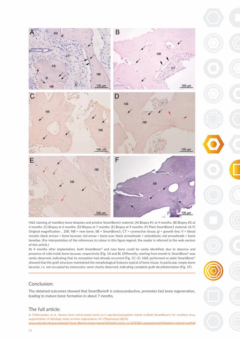
Conclusion:The obtained outcomes showed that SmartBone® is osteoconductive, promotes fast bone regeneration, leading to mature bone formation in about 7 months.
The full article:D. D’Alessandro, et al., Bovine bone matrix/poly(L-lactic-co-ε-caprolactone)/gelatin hybrid scaffold (SmartBone1) for maxillary sinus augmentation: A histologic study on bone regeneration, Int J Pharmaceut (2016)www.ncbi.nlm.nih.gov/pubmed/?term=Bovine+bone+matrix%2Fpoly(L-lactic-co-%CE%B5-caprolactone)%2Fgelatin+hybrid+scaffold
H&E staining of maxillary bone biopsies and pristine SmartBone1 material. (A) Biopsy #1 at 4 months. (B) Biopsy #2 at 4 months. (C) Biopsy at 6 months. (D) Biopsy at 7 months. (E) Biopsy at 9 months. (F) Plain SmartBone1 material. (A-F) Original magnification _ 200. NB = new bone; SB = SmartBone1; CT = connective tissue; gl = growth line; V = blood vessels; black arrows = bone lacunae; red arrow = bone scar; black arrowheads = osteoblasts; red arrowheads = bone lamellae. (For interpretation of the references to colour in this figure legend, the reader is referred to the web version of this article.)At 4 months after implantation, both SmartBone® and new bone could be easily identified, due to absence and presence of cells inside bone lacunae, respectively (Fig. 1A and B). Differently, starting from month 6, SmartBone® was rarely observed, indicating that its resorption had already occurred (Fig. 1C–E). H&E performed on plain SmartBone®
showed that the graft structure maintained the morphological features typical of bone tissue. In particular, empty bone lacunae, i.e. not occupied by osteocytes, were clearly observed, indicating complete graft decellularization (Fig. 1F).

2016 | Clinical Oral Investigation
Authors: Cohen O., Ormianer Z., Tal H., Rothamel D., Weinreb M., Moses O.
Study device:1. Alpha-Bio Tec ICE dental implants.2. Alpha-Bio Tec SPI dental implants.
Study Objective:The aim of the study was to compare bone-to-implant contact (BIC) between implants inserted at high torque (≥35 Ncm) due to under-drilling of the crestal bone to those inserted at low torque (<10 Ncm) due to over-drilling of the crestal bone.
Study design:Ten male New Zealand white (NZW) rabbits at 21–23 weeks of age (3–3.5 kg) were used in this study. In each tibia, one implant of under-drilling (UD) and one of the over-drilling (OD) were inserted alternately. A total of four implants (two OD and two UD) were installed in each rabbit. In the UD group, SPI® implants with a coronal diameter of 3.75 mm were inserted with bicortical stabilization at torque ≥35 Ncm. In the OD group, ICE implants with a coronal diameter of 3.55 mm were inserted with torque of <10 Ncm.X-rays of the tibiae were taken before and following surgeries to verify the implant location. Twenty-one days following the first implantation, the left leg was subjected to the same surgical procedure. (Fig.1)The animals were sacrificed 6 weeks after the second surgery implantation. The extracted blocks containing implants were dissected and stained with toluidine blue for evaluation of new bone formation. Crestal bone-to-implant contact (c-BIC, within the crestal compact bone) and total BIC (t-BIC, along the entire implant) were calculated with ImageJ at a magnification of ×100.
25
Differences in crestal bone-to-implant contact following an under-drilling compared to an over-drilling protocol. A study in the rabbit tibia11
10 Rabbits
Under-drilling SPI Over-drilling ICERight leg Day 0
Under-drilling SPI Over-drilling ICELeft leg Day 21
6 weeks
Fig 1.

26
Results:Histological examination revealed that at 3 weeks, implants inserted with an under-drilling (UD) protocol presented areas of bone resorption along the thread pitch while areas of new bone formation were observed within the thread valleys. (Fig 2-3,5) At 6 weeks, histological sections of both groups presented extensive bone remodeling. No differences in t-BIC were noted at 3 weeks (18.3 ± 1.6 vs 14.6± 1.3 %) and at 6 weeks (21.8 ± 1.9 vs 23.8± 2.0 %) between the OD and UD groups, respectively. (Fig. 4)
Fig. 2 Micrograph of a whole implant. A represents the region of crestal cortical bone-to-implant contact (c-BIC). B represents the region of total bone-to-implant contact (t-BIC). Magnification ×10
Fig. 3 Micrographs of a 3-week site.a Representative section of an implant from the UD group. Bone resorption is seen in areas ofthe thread pitch while new bone formation is evident in the threads valley. A microcrack (marked by arrows) can be observed. b Representative section of an implant from the OD group. Extensive new bone formation along the implant surface can be identified. Magnification ×100

27
Fig. 4 Micrographs of 6-week sites. a Representative section of an implant from the UD group. b Representative section of an implant from the OD group. Bone remodeling and maturation are apparent in both sections with a more mature bone in the OD group section. Magnification ×100
Fig. 5 Mean (±se) c-BIC at 3 weeks (3W) of implants inserted with an over-drilling protocol (OD) and implants inserted with an under-drilling protocol (UD). * denotes p <0.05
Conclusion:Within the limitations of the present study, insertion of implants with a high torque following an under-drilling protocol (commonly used for immediate loading) may reduce short term crestal bone-to-implant contact. On the other hand, over-drilling of the crestal aspect of the osteotomy may result in increased crestal bone-to-implant contact. Further studies using other implant systems and animal models should be conducted to confirm these results.
The full article:Cohen O, Ormianer Z, Tal H, Rothamel D, Weinreb M, Moses O.; Differences in crestal bone-to-implant contact following an under-drilling compared to an over-drillingprotocol. A study in the rabbit tibia. Clin Oral Investig. 2016 Dec;20(9):2475-2480www.ncbi.nlm.nih.gov/pubmed/26931772

2016 | Journal of Prosthetic Dentistry
Authors: Kohen J., Matalon S., Block J., and Ormianer Z.
Study device:1. Alpha-Bio Tec ICE dental implants.2. Alpha-Bio Tec DFI dental implants.3. Alpha-Bio Tec Arrow dental implants.
Study Objective:The purpose of this study was to compare the long-term outcomes of different implant insertion and loading protocols on crestal bone loss.
Study design:This retrospective comparative study was performed on a data of 1688 implants that wereimplanted in 343 patients. (Fig. 1)
28
Effect of implant insertion and loading protocol on long-term stability and crestal bone loss: A comparative study12
86 Maestro biohorizons
343 patients = 1688 implants
241 TSV zimmer62 arrow implants911 DFI388 SPI
Fig 1. Distribution of included implants
Patients’ records were thoroughly reviewed for medical and dental histories, detailed clinical and radiographic examination, including CT scans, evaluations of oral hygiene, and performance of at least 1 annual hygiene prophylaxis and clinical monitoring. This study spanned 15 years, during which different materials and methods were in use. The surgical procedures were performed by 2 periodontists, 3 maxillofacial and oral surgeons, and 1 general practitioner. The implantation area was incised and flap was elevated. When the socket was more than 1 mm wider than an implant, a bone augmentation was performed with autogenic bone or Bio-Oss (Bio-Oss, Geistlich Sons Ltd.) At the end of the implant placement procedure, the implants were covered with soft tissue, covered with a healing cap, or restored with an interim restoration. Definitive restorations were fabricated 3 to 6 months after implant insertion.

29
61 late implantation (4-6 m)
Implant placement
Fig 2. Implant placement methods
1317 immediate implantation 310 delayed implantation (6-8 w)
All included in the study implants were divided into 3 different implant placement methods: (Fig. 2)1. The teeth were extracted and implants were placed immediately.2. Implants were placed 6 to 8 weeks after tooth extraction.3. Implants were placed 4 to 6 months after tooth extraction. (Typically for patients with sinus lift augmentation).
Fig 3. Loading methods
The average follow-up time was 107 months.
212 delayed (3-6 m)
Loading protocol
1203 immediate 273 early (4-10 w)
3 types of loading were implemented: (Fig. 3)1. Restorations were fabricated and delivered with the occlusal contacts on the placed implants.2. Implants were loaded within 4 to 10 weeks.3. Implants were loaded 3 to 6 months after implant placement.
Results:The cumulative implant survival rate was 95.6%, and the average bone loss was 2.03 mm. No statistically significant differences in bone loss among the different insertion and loading protocol groups.In further statistical analysis was shown statistically significant effect of SPI implant showing less bone loss than DFI (P=.015), regardless of the insertion and loading protocol.
Conclusion:Within the limitations of this study, the 3 implant insertion and loading protocols were found to have similar success rates for implant survival, but with marginal differences in bone loss that were not statistically significant. Further analysis of the study groups revealed that SPI types demonstrated less bone loss than DFI types, regardless of the insertion and loading protocol.
The full article:Kohen J, Matalon S, Block J, Ormianer Z.; Effect of implant insertion and loading protocol on long-term stability and crestal bone loss: A comparative study. 2016 J Prosthet Dent. Jun;115(6):697-702www.ncbi.nlm.nih.gov/pubmed/26803177

2016 | Implant dentistry
Authors: Ormianer Z., Matalon S., Block J., Kohen J.
Study device:1. Alpha-Bio Tec DFI dental implants.2. Alpha-Bio Tec Arrow dental implants.3. Alpha-Bio Tec SPI dental implants.
Study Objective:The aim of this study was to compare long-term bone loss around dental implants with 3 different thread designs. The 3 implant types studied are from the same company and have the same microstructured surface. Survival rates and average bone loss were evaluated.
Study design:1361 implants were included in the study. The average follow-up time in this study was 107 months, with a minimum follow up time of 82 months. The implants were divided into 3 groups according to the implant type.
30
Dental Implant Thread Design and the Consequences on Long-Term Marginal Bone Loss13
911 DFI implants
1361 implants
388 SPI implants 62 arrow implants
Results:Overall survival rate was 96.3% with 50 implant failing (3.7%) out of 1361 implants. Survival rates for the 3 groups were: group SPI 96.6%, group DFI 95.9%, and in group Arrow 100%. Average bone loss for groups SPI, DFI, and Arrow were 2.02 (±1.70) mm, 2.10 (±1.73) mm, and 1.90 (±1.40) mm, respectively.

31
Average mesial-distal bone loss as measured from implant/abutment connection to bone level. The average bone loss was 2.02 (61.70) mm for group A, 2.10 (61.73) mm for group B, and 1.90 (61.40) mm for group C.
Conclusion:Favorable long term bone loss results were found in implants with a larger pitch, deeper apical threads, and a narrower implant core (SPI). One-piece V-thread design implants (Arrow) demonstrated 100% survival rate.
The full article:Ormianer Z., Matalon S., Block J., and Kohen J.; Dental Implant Thread Design and the Consequences on Long-Term Marginal Bone Loss. Implant Dentistry 2016:25 Number 4, 471-477www.ncbi.nlm.nih.gov/pubmed/27455430
Implant Type
Bone
loss
(mm
)
SPI DFI Arrow

2000 | The Journal of Prosthetic Dentistry
Authors: Weiss EI., Kozak D., Gross MD.
Study device:Morse tapered straight abutment.
Study Objective:The purpose of this study was to compare torque loss as a result of multiple consecutive closures withinand between systems.
Study design:Seven Abatment/Implant systems were used to test changes in opening torque after multiple consecutive closures at a constant closing torque. All systems were closed in 20N/cm. After a resting period of 10 seconds, the abutment screw was opened and the opening torque recorded by a second operator. This procedure was repeated for 200 consecutive closing/opening cycles.
32
Effect of repeated closures on opening torque values in seven abutment-implant systems14
Fig 1. Schematic diagram represents sections of 7 abutment/implant assemblies showing interface and attached abutments. A, Spline; B, Steri-Oss external hex; C, Brånemark external hex; D, Omniloc internal octagon; E, ITI morse taper; F, Alpha-Bio, morse taper; G, Integral peripheral rim only.

Results:A progressive decrease in opening torque values was measured in all implant systems. Significant differences were found between A/I systems. Systems with morse tapered and spline connections consistently maintained a higher resistance to opening force. Percentage torque loss ranged from 3% to20% on immediate opening, and from 4.5% to 36% for average of first 30 opening/closing cycles.
33
Fig 3. Opening torque values after 200 consecutive repeated closures at 20 N/cm. Jagged lines depict mean opening torque of 3 samples for each of 7 A/I systems. (1) ITI, (2) Alpha-Bio, (3) Spline, (4) Integral, (5) Steri-Oss, (6) Omniloc, (7) Brånemark (seized at average of 32 closures). Solid smooth lines represent trend lines for data of 7 implant systems.
consecutive openings
N-c
m
Conclusion:Repeated opening and closing of implant abutment screws caused progressive loss of torque retention with variations between systems. This was probably due to a decrease in the coefficient of friction between the mating components. It is advisable to reduce the number of opening/closing cycles in clinical and laboratory procedures before final abutment closure to reduce the risk of screw loosening.
The full article:Weiss EI., Kozak D., Gross MD.; Effect of repeated closures on opening torque values in seven abutment-implant systems 2000 J Prosthet Dent;84:194-9www.ncbi.nlm.nih.gov/pubmed/10946337

2016 | Clinical Oral Investigations
Authors: Fienitz T., Moses O., Klemm C., Happe A., Ferrari D., Kreppel M., Ormianer Z., Gal M., Rothamel D.
Study device:1. Alpha Bio’s Graft® Natural Bovine Bone 1-2-mm, sintered bovine bone matrix (SBM), Alpha Bio, Petach Tikva, Israel2. Alpha-Bio Tec SPI dental implants3. BioOss® 1–2-mm, non-sintered bovine bone matrix (NSBM), Geistlich Biomaterials, Wolhusen, Switzerland) - Control
Study Objective:The aim of the present study was to compare two different xenogeneic materials, a sintered and a non-sintered bovine bone substitute material, in sinus augmentations using histological and radiological analysis.
Study design:44 sinuses were allocated to the non-sintered or sintered group using a standard randomization protocol. Eleven bilateral and 22 unilateral sinuses in 33 patients were included in the study. Patients with bilateral sinus augmentations were treated in a split mouth design.The study consisted of two surgical phases. In the first phase, the sinus augmentation was performed. In the second surgical phase, and implant installation was performed following a healing period of 6 months and radiological control. Prior to implantation, a bone biopsies were taken. (Fig. 1)
34
Histological and radiological evaluation of sintered and non-sintered deproteinized bovine bone substitute materials in sinus augmentation procedures. A prospective, randomized-controlled, clinical multicenter study
15
33 patients (44 sinuses)
Fig 1. Study design
Non-Sintered - NSBM, Bio Oss® (Geistlich) Sintered bone - OLD ABT graft (Botiss)
Sinus lift 6 months Implant installation

Histological evaluation was performed using a light microscope connected to a camera. Pristine bone and augmented bone areas were identified according to the presence of bone substitute material particles. The grafted area was defined as “area of interest” and used for histomorphometrical evaluation. For each augmentation site, the “area of interest” was evaluated using a quantitative colour analysis with special regard to the following parameters:
• Percentage of new bone matrix (NBM)• Percentage of bone substitute material (BSM)• Percentage of non-mineralized tissue (NMT)
Results:Out of total enrolled subjects, 1 subject had left the study. In the present study, two different xenogeneic bone substitute materials were evaluated in external sinus floor elevation procedures. Although both materials differ significantly in terms of processing temperature, no significant differences were found in terms of volume stability and new bone formation, as well as remaining bone substitute material and non mineralized tissue after six months of healing. No difference in the resorption rates of the tested bone substitute materials if same particle sizes are used. (Fig. 2)
Conclusion:Sinus augmentations are a useful procedure to enable implant placement in the atrophic maxilla. Both examined xenogeneic bone substitute materials showed comparable results regarding new bone formation and height changes of the augmented sites and might be equally useful to support bone formation in the elevated sinus.
The full article:Fienitz T, Moses O, Klemm C, Happe A, Ferrari D, Kreppel M, Ormianer Z, Gal M, Rothamel D; Histological and radiological evaluation of sintered and non-sintered deproteinized bovine bonesubstitute materials in sinus augmentation procedures. A prospective, randomized-controlled, clinicalmulticenter study. Clin Oral Investig. 2016 Apr 30www.ncbi.nlm.nih.gov/pubmed/27129584
35
Fig 2. histology slides (small image magn. X12.5. big image magn. X100)
BIOOSS Alpha-Bio Tec.
(A) Bone substitute (#) and newly formed bone (*) are showing similar staining behaviour(B) The sintered hydroxyapatite (#) is in close contact to the newly formed bone (*) and does not uptake the dye based on its fully mineral composition
In addition, the histological analysis revealed comparable results for the sintered and the non-sintered xenogeneic bone substitute material.
A B

Posters

[16]Narrow vs. standard implants in one-step flapless approach. One year follow-up
[Page 38]
[17]Intra-sinus bone evolution around implants placed using Flaplessand graftlesstranscrestalsinus floor elevation: 5 years follow-up
[Page 39]
[18]Temperature changes in one-piece implants due to provisional restoration. The effect of implant diameter. An in vitro study
[Page 40]
[19]Endo-sinus bone gain in case of lateral sinus floor elevation with immediate implant placement without grafting material
[Page 41]

Topic: Implant therapy outcomes, surgical aspect
References
Conclusions
Background and Aim
Narrow vs. standard implants in one-step flapless approach.One year follow-up.
Mostovei A., Topalo V., Chele N., Sirbu D., Atamni F., Gumeniuc A., Mostovei M.
The State Medical and Pharmaceutical University “Nicolae Testemitanu”
338
1. Mostovei A. Formarea spațiului biologic periimplantar în tehnica flapless în dependență detipul mucoasei, Buletinul Academiei de Științe a Moldovei, 2013; 3(39): 180-184, ISSN1857-0011.
2. Mostovei A., Formarea spațiului biologic periimplantar în tehnica fără lambou în dependențăde tipul mucoasei și profunzimea instalării implanturilor, Medicina Stomatologica, 2013;3(28): 53-58.
3. Sarment D., Meraw S. Biological Space Adaption to Implant Dimensions. In: TheInternational Journal of Oral & Maxillofacial Implants. 2008, vol. 23, nr.1, p.99-104.
4. Tabassum A., Meijer G., Walboomers X. et al. Evaluation of primary and secondary stabilityof titanium implants using different surgical techniques. In: Clin. Oral Impl. Res. 2014,vol.25, nr.4, p.487-492.
5. Topalo V., Chele N., Mostovei A. et al. The implant position influence upon crestal-boneusing one-step flapless surgery. In: Clinical Oral Implants Research. Copenhagen,Denmark, 2012, vol.23, nr.7(suppl.), p.28.
6. Weber HP, Busher D., Donath K. et al. Comparison of healed tissues adjacent tosubmerged and non-submerged unloaded titanium dental implants. A histometric study inbeagle dogs. In: Clin Oral Impl Res. 1996, nr.7, p.11-19.
In case of one-step placement of two-piece dental implants, the early boneloss begins from the moment of implant insertion, whilst in the two-stepsapproach – after the second surgical step. In such situations, the flaplessapproach has a positive effect upon biological width formation. It is necessary tostate the effect of implant diameter and platform switching upon crestal bone lossin case of one-step flapless placement of two-piece dental implants.Aim
To appreciate the influence of the diameter of implants and the switch platformeffect upon crestal bone modeling in case of one-step flapless placement of two-piece dental implants.
One hundred and twenty five Alpha-Bio Tec Implants (SPI) were inserted in 69patients (45±1,98 years) in the posterior sides of the mandible, using one-stepflapless approach (with immediate connection of healing abutments). Seventyimplants had the diameter of 3,3 and 3,75mm (Control) whilst the rest 55 implants– 4,2 and 5mm (Study Group, with the effect of platform switching). The socketpreparation was initiated using spade bur, through the mucosa, without removingany part of it, and then the recommended surgical protocol was used (Figure 1).The integrity of the bone walls as well as the mucosal thickness at the top of thecrest was checked with periodontal probes. The mean healing period was13,67±1,05 (Control) and 13,03±1,03 (Study) weeks. At the end of the healingperiod the pre-prosthetic evaluation were performed. One implant from controlgroup failed during healing. According to the orthopantomogram, implants’ sideswere divided into anterior and posterior ones. Due to the relation between bonecrest and implant platform, three positions have been distinguished: supracrestal,at the bone level and subcrestal. The following parameters were evaluated:primary and secondary stability (Periotest Classic), peri-implant bone modelingusing Adobe Photoshop CS3 Program (at the end of the healing period and 1 yearpost-prosthetic). Statistical analysis was made by calculating mean values,standard errors, indices of Student’s paired t test and Mann-Whitney U tests.
Primary stability was -6,18±0,116(Study) and -5,91±0,106 (Control) while thesecondary were -6,09±0,104 (Study) and -5,85±0,111Control (p>0,05). In theStudy Group, the periimplant bone loss at mesial and distal aspects were:0,72±0,068mm and 0,48±0,05mm during healing period; 0,47±0,108mm and0,37±0,082mm at 1 year follow up (p>0,05). In the Control Group, theperiimplant bone loss at mesial and distal aspects were: 0,63±0,052mm and0,48±0,047mm during period; 0,44±0,121mm and 0,54±0,219mm at 1 yearfollow up (p>0,05). The bone apposition has been observed around 2 Study and10 Control implants (all in supracrestal position). There was no statisticaldifference between bone loss of both groups, neither during healing, nor 1 yearpost-prosthetic. A statistical difference has been observed between bone lossvalues of supracrestal implants position versus subcrestal ones (p<0,01 formesial and p<0,05 for distal aspects) with lowest values in supracrestal position.
The implant diameter as well as the platform switching effect seems to have noinfluence upon periimplant bone level and implants’ stability during healing and 1year post-prosthetic. The relation between the implant platform (microgap) andbone crest has a significant impact upon periimplant bone modeling, supracrestalposition showing lowest bone loss values. The summary bone loss from theplacement to 1 year follow up does not exceed values described in the literaturefor other implant types.
Abstract Results
Methods and Materials
Presented at
Numerous studies are published regarding the bone loss around narrow andwider diameter implants. Moreover, the effect of platform switching is also anintense discussed theme in the literature and the opinions about these twoproblems are divergent. Another factor which may influence the periimplant boneloss is the implant shoulder design. In some implants, due to constant platformdimensions, platform switching concept appears with the increasing of implantdiameter. In order to achieve a correct opinion, it is necessary to appreciate theinfluence of implant diameter and the platform switching concept upon bone lossfor each system separately.
Fig.1 Flapless implant placement (SPI 4,2-13mm): preoperative view (a); after socket preparation (b); implant insertion (c); aspect of implantplatform before healing abutment connection(d); healing abutment connection (e); primary stability appreciation (f); postoperative radiographicview (g); peri-implant mucosa at the end of healing period (h) and radiographic view (i); aspect of the prosthesis one-year after loading andradiographic view (j,k,l);
a cb
e
d
f g h
i j k l
38
16

39
17Topic: Implant therapy outcomes, surgical aspects
References
Conclusions
Background and Aim
Intra-sinus bone evolution around implants placed using Flapless and graftless transcrestal sinus floor elevation: 5 years follow-up.
Topalo Valentin, Mostovei Andrei, Chele Nicolae, Atamni Fahim, Sirbu DumitruThe State Medical and Pharmaceutical University „Nicolae Testemitanu”
PSA 333
1. Topalo V., Mostovei A., Atamni F., Sirbu D. Intra-sinus bone evolution around implants placed using Flapless and graftless transcrestal sinus floor elevation: 3 years follow-up. In Clin. Oral Impl. Res. 2014. Vol. 25(Suppl.10), p.374.
2. Atamni F., Topalo V., Mostovei A., Chele N. Flapless and graftless transcrestal sinus floor elevation – onestep placement of two-stage dental implants. Clinical Oral Implant Research, 2013; 24(9): 105-106.
3. Topalo V., Mostovei A., Chele N., Sîrbu D., Suharschi I., Atamni F., Mostovei M. METODĂ DE EVALUARE A REMANIERILOR OSOASE PERIIMPLANTARE. În: Medicina Stomatologica. Chișinău, 2015. Nr.1, p.43-47.
Implant placement using osteotome technique for sinus floor elevation isa widely used and discussed method. Usually, during surgery, graftingmaterial is protruded in the preparation site in order to complete thespace between sinus floor and the elevated membrane as well as todecrease the shrinkage of intra-sinus bone during years. There arestudies which demonstrate good and predictable results without usingbone grafting material. Moreover, a native bone can adapt andphysiologically handle the functional loading regardless the grafted bonytissue. It is necessary to appreciate the integration process, endo sinusbone formation and its evolution around implants installed using flaplessapproach, without condensation and without grafting material.
Aim: To evaluate the intra-sinus bone evolution around implantsinstalled using flapless transcrestal sinus floor elevation, without bonecondensation and without grafting material during 5 years follow-up.
The transcrestal sinus floor elevation during implants placement is awidly discussed theme in the literature. This study describes the resultsof 5 years follo-up of intrasinus and cortical periimplant bone modellingin case of transcrestal sinus floor elevation without bone condensationand grafting material.
The residual bone height on anterior and posterior sides consisted7.88±0.778mm and 7.18±0.611mm. The degree of implant penetrationinto the sinus was 1.95±0.305mm and 2.08±0.433mm respectively. Thebone clot after implant placement was 2.88±0.315mm and3.01±0.438mm. During healing, a shrink of 0.84±0.36mm and0.81±0.215mm occurred and an amount of 2.03±0,438mm and2.19±0.425mm of new formed bone at the 2nd stage was observed.Five years post-prosthetic, the height of intra-sinus bone was:2.22±0,454mm and 1.66±0.463mm. During this period, around 5implants from anterior and 4 implants from posterior a shrink of0.63±0.311mm and 0.73±0.293mm occurred, while the other onesshowed a bone apposition of 1.27±0.04mm and 0.67±0.32mm. Thecrestal bone loss occurred between implant placement and 5 yearspost-prosthetic were 0.87±0.33mm from mesial and 0.92±0.382mmfrom distal aspects. The endo-sinus bone gain have a strong directcorrelation with implant protruded height: mesial r=0.602 and distalr=0.886.
The implant placement by the described method leads to good andpredictable results. During 5years follow-up, the endo-sinus new formedbone remodeling manifested by a small shrink just for a part of implants,while other showed an increasing of bone height. A shrink less than1mm in 5 years after prosthetic delivery demonstrates the possibility ofavoiding grafting materials for transcrestal sinus floor elevations.
Abstract Results
Methods and Materials
Add contact info:[email protected]
to access the posters online, please download the application
Five partially edentulous patients (mean age 41±1,37 years) received10 two-stage dental implants (Alpha-Bio Tec, SPI, with diameter 3,75to 5mm, and 8 to 11,5mm length) in posterior sides of upper jaw. Thefirst surgical step was performed using flapless approach, usingosteotomes for sinus floor fracture, without bone condensation andgrafting material. All implants were installed in sites with D3 bonedensity (according to Misch). No perforation of the sinus membranehas been observed before implant insertion. According toorthopantomogram, implants sides were divided into anterior andposterior ones. Radiographic images were analyzed using PhotoshopCS3 Program. The following indices were evaluated: residual boneheight, the length of implant penetration into sinus, endo-sinus boneclot height, endo-sinus bone gain and evaluation of it during 5 yearsafter prosthetic delivery. Crestal bone loss during this period was alsoevaluated. After a healing time of 6,3±0,42 months, the second stagewas performed and prosthetic treatment was initiated after 2-4 weeks.All implants successfully integrated. The intra-sinus bone formationduring healing and its evolution for a period of 5 years post-prostheticwere analyzed. Statistical analysis was made by calculating meanvalues and standard errors as well as Pearson’s Correlation test.
Fig.1. Radiographic aspects:preoperative (a); postoperative(b); at the end of healing (c); 5years of after loading (d);intraoral aspect (e,f).
Fig.2. Radiographic aspects: preoperative (a); postoperative (b); at the end of healing (c); 3 years of after loading (d); 5 years of after loading (e);
a b c d e
c d e f
a b
Topic: Implant therapy outcomes, surgical aspects
References
Conclusions
Background and Aim
Intra-sinus bone evolution around implants placed using Flapless and graftless transcrestal sinus floor elevation: 5 years follow-up.
Topalo Valentin, Mostovei Andrei, Chele Nicolae, Atamni Fahim, Sirbu DumitruThe State Medical and Pharmaceutical University „Nicolae Testemitanu”
PSA 333
1. Topalo V., Mostovei A., Atamni F., Sirbu D. Intra-sinus bone evolution around implants placed using Flapless and graftless transcrestal sinus floor elevation: 3 years follow-up. In Clin. Oral Impl. Res. 2014. Vol. 25 (Suppl.10), p.374.
2. Atamni F., Topalo V., Mostovei A., Chele N. Flapless and graftless transcrestal sinus floor elevation – one step placement of two-stage dental implants. Clinical Oral Implant Research, 2013; 24(9): 105-106.
3. Topalo V., Mostovei A., Chele N., Sîrbu D., Suharschi I., Atamni F., Mostovei M. METODĂ DE EVALUARE A REMANIERILOR OSOASE PERIIMPLANTARE. În: Medicina Stomatologica. Chișinău, 2015. Nr.1, p.43-47.
Implant placement using osteotome technique for sinus floor elevation isa widely used and discussed method. Usually, during surgery, graftingmaterial is protruded in the preparation site in order to complete thespace between sinus floor and the elevated membrane as well as todecrease the shrinkage of intra-sinus bone during years. There arestudies which demonstrate good and predictable results without usingbone grafting material. Moreover, a native bone can adapt andphysiologically handle the functional loading regardless the grafted bonytissue. It is necessary to appreciate the integration process, endo sinusbone formation and its evolution around implants installed using flaplessapproach, without condensation and without grafting material.
Aim: To evaluate the intra-sinus bone evolution around implantsinstalled using flapless transcrestal sinus floor elevation, without bonecondensation and without grafting material during 5 years follow-up.
The transcrestal sinus floor elevation during implants placement is awidly discussed theme in the literature. This study describes the resultsof 5 years follo-up of intrasinus and cortical periimplant bone modellingin case of transcrestal sinus floor elevation without bone condensationand grafting material.
The residual bone height on anterior and posterior sides consisted7.88±0.778mm and 7.18±0.611mm. The degree of implant penetrationinto the sinus was 1.95±0.305mm and 2.08±0.433mm respectively. Thebone clot after implant placement was 2.88±0.315mm and3.01±0.438mm. During healing, a shrink of 0.84±0.36mm and0.81±0.215mm occurred and an amount of 2.03±0,438mm and2.19±0.425mm of new formed bone at the 2nd stage was observed.Five years post-prosthetic, the height of intra-sinus bone was:2.22±0,454mm and 1.66±0.463mm. During this period, around 5implants from anterior and 4 implants from posterior a shrink of0.63±0.311mm and 0.73±0.293mm occurred, while the other onesshowed a bone apposition of 1.27±0.04mm and 0.67±0.32mm. Thecrestal bone loss occurred between implant placement and 5 yearspost-prosthetic were 0.87±0.33mm from mesial and 0.92±0.382mmfrom distal aspects. The endo-sinus bone gain have a strong directcorrelation with implant protruded height: mesial r=0.602 and distalr=0.886.
The implant placement by the described method leads to good andpredictable results. During 5years follow-up, the endo-sinus new formedbone remodeling manifested by a small shrink just for a part of implants,while other showed an increasing of bone height. A shrink less than1mm in 5 years after prosthetic delivery demonstrates the possibility ofavoiding grafting materials for transcrestal sinus floor elevations.
Abstract Results
Methods and Materials
Add contact info:[email protected]
to access the posters online, please download the application
Five partially edentulous patients (mean age 41±1,37 years) received10 two-stage dental implants (Alpha-Bio Tec, SPI, with diameter 3,75to 5mm, and 8 to 11,5mm length) in posterior sides of upper jaw. Thefirst surgical step was performed using flapless approach, usingosteotomes for sinus floor fracture, without bone condensation andgrafting material. All implants were installed in sites with D3 bonedensity (according to Misch). No perforation of the sinus membranehas been observed before implant insertion. According toorthopantomogram, implants sides were divided into anterior andposterior ones. Radiographic images were analyzed using PhotoshopCS3 Program. The following indices were evaluated: residual boneheight, the length of implant penetration into sinus, endo-sinus boneclot height, endo-sinus bone gain and evaluation of it during 5 yearsafter prosthetic delivery. Crestal bone loss during this period was alsoevaluated. After a healing time of 6,3±0,42 months, the second stagewas performed and prosthetic treatment was initiated after 2-4 weeks.All implants successfully integrated. The intra-sinus bone formationduring healing and its evolution for a period of 5 years post-prostheticwere analyzed. Statistical analysis was made by calculating meanvalues and standard errors as well as Pearson’s Correlation test.
Fig.1. Radiographic aspects:preoperative (a); postoperative(b); at the end of healing (c); 5years of after loading (d);intraoral aspect (e,f).
Fig.2. Radiographic aspects: preoperative (a); postoperative (b); at the end of healing (c); 3 years of after loading (d); 5 years of after loading (e);
a b c d e
c d e f
a b

Topic: Basic research
References1. Prithviraj DR, Gupta V, Muley N, Sandhu P (2013).
One-piece implants: placement timing, surgical technique,
loading protocol, and marginal bone loss.
J Prosthodont 22:237-244.
2. Parel SM, Schow SR (2005)
Early clinical experience with new one-piece implant
system in single tooth sites. J Oral Maxillofac Surg 63:2-10
Conclusions
Direct application of auto-polymerizing resin to the titanium abutment of
one-piece implants significantly increased the cervical implant
surface temperature. Implant diameter
did not influence the temperature changes.
Objectives
To evaluate changes in temperature of one-piece titanium implant surface
during the setting of acrylic resin temporary crowns and to correlate
thermal changes to implant diameter.
PBR187
BackgroundLimited number of studies investigated heat production during
provisional restoration of implant abutment. Exposure of osteoblast culture
to 42 ºC induced activation of apoptosis mechanisms
To the best of our knowledge, heat production during provisional restoration
of one-piece implants was
never studied before.
Methods and Materials
Thirty-three one-piece implants (ARRP, Alpha-Biotec, Israel) were divided
into 3 groups according to diameter size (G1=3 mm, G2=3.3 mm,
G3=3.6 mm). Implants were mounted on an acrylic glass apparatus.(Fig 1.)
Thermocouples were positioned at the most coronal thread. Lower incisor
temporary polycarbonate crowns were filled with 80 µL of self-curing acrylic
resin and positioned immediately on the implant abutment.(Fig 2.)
Thermal changes of the implant surface were recorded continuously
for 10 minutes. Data were statistically analyzed using one-way analysis of
variance.
contact info: Prof. Ofer [email protected] access the posters online,
please download the application
*Ofer Moses, *Shimshon Slutzki, **Shlomo Matalon, *Omer Cohen
*Dep. of Periodontology & Dental Implantology, **Dep. Of Prosthodontics
School of Dental Medicine,Tel Aviv University, Israel.
Temperature changes in one-piece implants due to provisional restoration. The effect of implant diameter. An in vitro study.
Results
The mean initial temperature (C0) of groups G1, G2 and G3 was
similar (24.79±0.78ºC, 25.26±0.63ºC, 24.97±1.06ºC, respectively).
(Fig 3). The setting of the acrylic resin temporary crown resulted in a
significant increase in the implant surface temperature of all groups.
The mean thermal amplitude (ΔC) for groups G1, G2 and G3 were
6.79±1.02ºC, 6.61±0.94ºC, 6.65±1.26ºC, respectively. The mean time
to maximum temperature (Tmax) for groups G1, G2 and G3 were
337.38±42.91 seconds, 324.69±41.46 seconds and 317.98±37.91
seconds respectively (P>0.05). (Fig 4.)
Fig 1.
Fig1. Mounting and fixing of an implant into machined
slots in a custom-made acrylic glass apparatus
Fig 2.
Fig2. Placement of the filled crown on the implant
abutment while ensuring that no resin flows on the
implant surface.
Fig 3. An example of recorded temperature over time.
The thermal amplitude (ΔC) was calculated by
subtracting the initial change (C0) from the maximum
change (Cmax).
Fig 3.
Fig. 4 Baseline (C0) and maximal temperature (Cmax) recorded in groups: G1 (3.0 mm-implants), G2 (3.3 mm- implants), G3 (3.6 mm-implants). Data presented in Celsius degrees as mean value andstandard deviation. * denotes p<0.05
Fig 4.
Clinical relevance
To avoid thermal injury to the surrounding bone it is recommended to
constantly cool the implant with water spray during the setting of the
provisional restoration.
40
18

41
19

www.alpha-bio.net
R1/0
3.20
17
995
-851
7