Clearing the Air - Home - Tech Briefs Media Group · 2008 COMSOL NEWS A TECHNICAL COMPUTING...
36
2008 WWW.COMSOL.COM COMSOL NEWS A TECHNICAL COMPUTING MAGAZINE COMSOL NEWS Clearing the Air: Life Support for Space Exploration AUTOMOTIVE: SENSOR DESIGN 30 MANUFACTURING: MOLDING TECHNOLOGY 8 A TECHNICAL COMPUTING MAGAZINE Cov ToC + – ➭ ➮ A Intro
-
Upload
nguyennhan -
Category
Documents
-
view
216 -
download
0
Transcript of Clearing the Air - Home - Tech Briefs Media Group · 2008 COMSOL NEWS A TECHNICAL COMPUTING...

2008WWW.COMSOL.COM
COMSOLNEWS
A T E C H N I C A L C O M P U T I N G M A G A Z I N E
COMSOLNEWS
Clearing the Air: Life Support for
Space Exploration
AUTOMOTIVE:SENSOR DESIGN
30
MANUFACTURING:MOLDING TECHNOLOGY
8
A T E C H N I C A L C O M P U T I N G M A G A Z I N E
01-CN Cover 2008.indd 1 3/25/08 4:22:59 PMCov ToC + – ➭
➮
AIntro
COMSOL MultiphysicsTen Years of Unlimited Simulation Capabilities!
In 1998 COMSOL Multiphysics® made its
debut as the first commercial environ-
ment to enable scientists, engineers, and
researchers to solve any system of coupled
physics phenomena in the same simulation.
Ever since, users have leveraged the insights
of multiphysics modeling and simulation to
work smarter.
In this issue of COMSOL News, you’ll find 15
examples of how your colleagues use COM-
SOL to take on today’s technological chal-
lenges. We have a report from a team at NASA
Marshall Space Flight Center that’s modeling
next-generation life support systems for long-
duration space habitation such as a lunar out-
post and a roundtrip to Mars. Next, you can
learn how multiphysics helps France’s Roc-
Tool, which specializes in licensing its rapid
molding technologies for the composites in-
dustry, customize molds for its clients’ diverse
needs. We also have two interesting examples
of multiphysics in the consumer products
industry: electric shavers from Philips and a
full-color, photo-quality direct thermal printer
from ZINK Imaging.
Odds are good that you will find many
great examples of multiphysics modeling in
this magazine, but it is just a sampling of the
multiphysics universe. The Conference CD
from last fall’s worldwide user conferences
has many more examples for you. In fact, the
CD contains more than 250 technical papers,
190 user presentations, 40 downloadable
models, and 90 video clips illustrating multi-
physics modeling across all disciplines of sci-
ence, industrial and space research, engineer-
ing, medical research, and education. Request
your free-of-charge CD at www.comsol.com.
We’re celebrating the 10th anniversary of
COMSOL Multiphysics. And we have a busy
year ahead with hands-on workshops around
the world, the 2008 Conference featuring
COMSOL 3.5, and much more. I hope to see
you there!
Bernt Nilsson
Sr VP of Marketing
COMSOL, Inc.
CONTENTS // COMSOL NEWS 2008
AEROSPACE
4 Clearing the Air: Life Support
for Space Exploration
7 Instrumentation Modeling
for NASA’s Next Mars
Rover Mission
MANUFACTURING
8 Innovative Molding Technology
11 Fluid-Structure-Acoustic
Interactions
12 Electrochemical Machining in
Appliance Manufacturing
14 Reduced Metal Consumption in
Electroplating Saves Big Money
BIO-MEDICAL
16 Faster, Safer delivery of
Therapeutic Substances
MATERIALS
18 A Model of Direct Thermal
Printing
20 Temperature Dependent
Material Properties
ELECTRICAL
22 Multiphysics Electrifies
Modeling in Many Scales
SEMICONDUCTORS
26 Improving Prediction
of Semiconductor Lifetimes
EDUCATION
28 In the Classroom: Rensselaer
Polytechnic Institute Puts
COMSOL to the Test
29 Engineers Advance Skills
AUTOMOTIVE
30 Rapid Developments of
Sensors in Vehicle Design
CLEAN ENERGY
32 Environmentally Friendly
Flameless Furnace
On the CoverThis concept image de-
picts a lunar lander in tran-
sit from Earth to the Moon.
COMSOL Multiphysics is
part of the toolset used
at NASA’s Marshall Space
Flight Center to develop
robust life-support systems for future long-term
space habitation. See page 4 for details.
Image courtesy of NASA Marshall Space Flight Center.
© 2008, all rights reserved. COMSOL News is
published by COMSOL, Inc. and its associated
companies.
COMSOL, COMSOL Multiphysics, COMSOL
Reaction Engineering Lab, COMSOL Script,
and FEMLAB are registered trademarks
of COMSOL AB. Other products or brand
names are trademarks or registered
trademarks of their respective holders.
We welcome your comments on COMSOL NEWS; contact us at [email protected].
2 // C O M S O L N E W S 2 0 0 8
34 Benchmarking COMSOL
Multiphysics
35 COMSOL Conference 2008
36 Guest Editorial: Dr. Dale Kipp
COLLABORATION
7 TransTech Systems becomes
COMSOL Certified Consultant
34 rbMIT ©MIT Software
FEATURES
DepArtments
02-CN Intro-Contents 2008.indd 2 3/26/08 1:55:19 PMCov ToC + – ➭
➮
AIntro

It’s too expensive to develop new technologies in the real world.
At Advanced Computational and Engineering Services, we are a team of engineers experienced in simulating real world events in a virtual environment. With our capability in multiphysics analysis, we can identify the interdependent effects of multiple, simultaneous physical phenomena,whether they be structural, fluid, acoustic, chemical, electromagnetic or thermal in nature. This allows you to rapidly screen concepts to increase the rate – and success – of new product development. It improves manufacturing processes as well.
Make your technologies a quicker and more profitable reality through our expertise in multiphysics engineering.
Contact us today:(614) 861-7015 www.acescolumbus.com
It’s too expensive to develop new technologies in the real world.
Develop them in ours.
03-CN Aces Ad 2008.indd 3 3/25/08 3:40:58 PMCov ToC + – ➭
➮
AIntro
4 // C O M S O L N E W S 2 0 0 8
AEROSPACENASA MARSHALL SPACE FLIGHT CENTER
An engineering requisite for all space
travel is to minimize power, weight,
and volume because all three translate to
mass for any launch system. Compared
to near-Earth missions such as the In-
ternational Space Station, manned lunar
outposts and long-duration space travel
present additional constraints that stress
system engineering. Chief among these
constraints is that every system must be
robust enough to operate for long periods
of time without compromising crew safe-
ty, without resupply, and without launch-
taxing extra mass such as spare parts or
a glut of backup equipment. Life support
systems are no exception.
At the Life Support Systems Develop-
ment Team of NASA’s Marshall Space
Flight Center in Huntsville, Alabama,
our task is to develop robust, yet mass-
minimizing, life support systems for long-
duration space travel, such as lunar ex-
ploration missions or a trip to Mars. Our
extended team includes the adsorption
experts at Vanderbilt University, led by
M. Douglas LeVan, and at the University
of South Carolina, led by James Ritter.
We are developing the next generation
of atmosphere revitalization systems,
which will reach for new levels of resource
conservation via a high percentage of loop
closure. For example, a high percentage
of carbon dioxide (CO2) exhaled by crew-
members can be converted by reaction
into clean water, closing the loop from
human metabolic waste to essential hy-
dration and hygiene supplies. Adsorption
processes play a lead role in these new
closed loop systems. Engineered struc-
tured sorbent (ESS) technologies have
attractive characteristics with the poten-
tial to reduce both complexity and overall
resource needs.
One new ESS technology we are inves-
tigating involves coating thermally and
electrically conductive (generally metal-
lic) substrates with molecular sieve sor-
bents. Use of a metallic substrate allows
for direct and efficient sorbent heating as
well as the capability to reduce the nega-
tive impacts of the heat of adsorption on
process efficiency.
But sorbent-coated metal technologies
present a number of tradeoffs in terms
of working capacity, mass, and volume.
Thus, the question becomes, are they
worth the effort? COMSOL Multiphysics
simulation plays a key role in our design
and analysis process as we investigate
that question.
Conflicts with Heating and CoolingThat sorbent-coated metal ESS tech-
nologies may offer the reduced resource
requirements needed for a long-term
life support system becomes apparent
in view of the physics underlying ad-
sorption and desorption processes. Heat
is produced during adsorption, yet the
resulting higher temperatures reduce
sorbent capacity and, therefore, inhibit
adsorption. Yet, during desorption heat
is lost and temperatures drop. While
cooling increases sorbent capacity, it im-
pedes desorption. The net effect of this
heating and cooling byproduct of the
adsorption process is a reduction in the
working capacity of a regenerative revi-
talization system.
One potential solution lies in transfer-
ring the heat between adjacent adsorp-
tion and desorption beds to approach an
isothermal process. This, along with the
capability for direct resistive heating, led
us to explore how Microlith substrates
from Precision Combustion Inc. and Elec-
tron Beam Melting (EBM) manufactured
substrates from Arcam behave when
coated with zeolites.
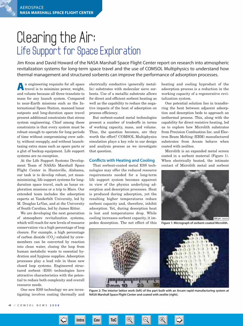
Microlith is an expanded metal screen
coated in a sorbent material (Figure 1).
When electrically heated, the intimate
contact of Microlith metal and sorbent
Clearing the Air: Life Support for Space ExplorationJim Knox and David Howard of the NASA Marshall Space Flight Center report on research into atmospheric revitalization systems for long-term space travel and the use of COMSOL Multiphysics to understand how thermal management and structured sorbents can improve the performance of adsorption processes.
Figure 1: Micrograph of sorbent-coated Microlith.
Figure 2: The interior lattice work (left) of the part built with an Arcam rapid manufacturing system at
NASA Marshall Space Flight Center and coated with zeolite (right).
04-05-06-CN NASA_Marshall 2008.i4 4 3/25/08 1:21:15 PMCov ToC + – ➭
➮
AIntro

C O M S O L N E W S 2 0 0 8 // 5
AEROSPACENASA MARSHALL SPACE FLIGHT CENTER
make for an efficient heat transport to the
sorbent. Arcam’s EBM rapid manufactur-
ing process uses an electron beam to melt
metal powder that then fuses, layer by
layer, into a part that might otherwise
be impossible to machine. Figure 2 shows
a lattice produced by this process at the
NASA Marshall Space Flight Center.
With these technologies appearing
hopeful, the next challenge facing us is
how to optimize the removal efficiency of
a coated metal sorbent module, and thus
reduce overall system volume. A second,
related question is what sort of perfor-
mance gains (and system size reductions)
can be realized by removing the heat of
adsorption during the CO2
and humidity
removal process? We address the second
question first.
Hot Beds of SorbentWe built models of sorbent beds using
COMSOL Multiphysics to learn more
about the thermal characteristics of vari-
ous sorbents undergoing different adsorp-
tion processes. To derive the linear driver
force (LDF) coefficient, which characteriz-
es the rate of mass transfer from sorbent
to gas and must be determined empirical-
ly for each sorbent-gas pair, we modeled
isothermal adsorption testing conducted
with a custom-built plate-finned heat ex-
changer packed with sorbent1. Due to the
relatively constant temperature within
the canister, the heat of adsorption could
be neglected, allowing the mass transfer
to be studied in isolation.
Testing began with a completely clean
sorbent bed and the introduction of CO2-
laden nitrogen. Initially, no CO2
exits
the bed, but then the CO2
outlet history
emerges in the classic S-curve shape of
a breakthrough curve. By adjusting the
LDF coefficient, we obtained a match be-
tween the actual test data and the simu-
lation data.
Since these simulations indicated our
adsorption model was on the right path,
our next step was to characterize the
thermal characteristics of a sorbent can-
ister and to determine the heat transfer
coefficient between the fluid and the sor-
bent and the fluid and the wall.
Here, we were looking at the heat
balance for the gas phase. This test-
ing started with a clean bed of sorbent
material and introduced 450 kelvin ni-
trogen, resulting in the large tempera-
ture swing shown in Figure 3. Model-
ing results following adjustment of the
heat-transfer coefficients (also shown in
Figure 3) provided a good match between
the test results and the simulation.
This gave us a usable characterization
of the system.
After some additional testing and simu-
lations, we were able to determine that
eliminating the heat of adsorption would
delay the initial breakthrough by about
an hour, not an insignificant amount of
time. If we could adjust the actual adsorp-
tion cycle to take advantage of this delay,
we could increase the adsorption perfor-
mance and, hence, the working capacity.
In a subscale test rig (Figure 4), we
proved that by recuperating the heat of
adsorption with an adjacent, thermally
linked desorbing bed during a vacuum
swing sorption cycle, we could nearly
eliminate the temperature swings of
up to 26° Fahrenheit observed in ther-
mally isolated beds. Thermally linking
adjacent beds was achieved by pack-
ing granular silica gel in metallic foam
filled beds. This approach allowed us to
increase the adsorption period from 15
minutes to 60 minutes while maintain-
ing a removal efficiency greater than
90% — a four-fold improvement in wa-
ter adsorption.
Thus we confirmed that, for a process
that approaches an isothermal vacuum
swing process, significant performance
benefits are realized during both adsorp-
tion and desorption. This is accomplished
by inhibiting the temperature swings that
result from the exothermic and endother-
mic nature of a cyclic sorption process.
Modeling the EBM ComponentThese results encouraged us to optimize
the removal efficiency of the coated metal
sorbent and thus reduce overall system
volume. Hardware and adsorption pro-
cess optimization requires understanding
the effect of varying substrate geometry
(metal strand size and spacing), process
(flow, desorption method, and cycle time),
and canister design (sorbent types and
quantities). Multiphysics simulation was
clearly required here to capture the ef-
fects of changing these parameters on the
fluid dynamics, transient mass transfer,
and transient heat transfer during the
adsorption process.
The top left image in Figure 5 shows a
simplified geometry of the interior lattice
of the EBM part to simulate alternative
interior design featuring metal rods with
a sorbent coating, with the rods connect-
ed thermally by a wall.
We then looked at a subset of this geome-
try (bottomleft imageFigure5).Thebottom
left image in Figure 5 is a 2D simulation of
a Navier-Stokes incompressible steady-
state analysis of the flow field around the
rods. The results obtained from COMSOL
showed that, although the flow around the
rods enters our adsorption chamber uni-
formly at y = 0, it quickly forms an estab-
lished, repeatable flow field.
With this data, we could simplify our
model and still obtain a reasonable an-
swer. Next, we examined the boundary
layer effects on the flow near the wall.
The top right image in Figure 5 shows the
3D simulation of flow through a bed of the
structured sorbent lattice. The similarity
of the flow pattern at varying distances
from the wall at the bottom indicates that
Figure 3: A comparison of test results and the COMSOL Multiphysics simulation characterized the heat transfer.
Figure 4: Subscale VSA test apparatus; results with a thermally linked bed showed a four-fold capacity improvement over thermally isolated sorbents beds.
04-05-06-CN NASA_Marshall 2008.i5 5 3/25/08 1:21:35 PMCov ToC + – ➭
➮
AIntro

6 // C O M S O L N E W S 2 0 0 8
AEROSPACENASA MARSHALL SPACE FLIGHT CENTER
the wall effect diminishes quickly away
from the wall.
Figure 6 shows the flow field in the
two exit planes along with the stream-
lines. Again, simulation shows that the
flow field becomes very consistent a short
distance away from the wall. This means
that we can use a small portion of the full
lattice to study the effects of changing rod
size, spacing, and geometry on the fluid
flow. The ultimate goal is to maximize the
mass transfer from the fluid to the sorbent
while minimizing the pressure difference
through the bed.
Where We Go From Here
So what does this all mean? It means
we have much more work to do. For
example, we plan to develop COMSOL
Multiphysics simulations of existing
subscale test articles, including EBM,
Microlith, and other ESS configurations.
The process parameters (cycle time,
flow rate, etc.) as well as the design and
structure of the coated metal latticework
will require more optimization through
simulation. Then we have to build and
test designs based on our simulations,
and compare ESS approaches against
packed bed sorbents, the present stan-
dard in the industry.
In short, we have years of research
prior to designing the atmospheric re-
vitalization system for lunar outposts
and the first human roundtrip to Mars.
COMSOL Multiphysics has played a key
role in our design and analysis process
thus far, and our hope is to continue to
use it extensively in the future.
DOWNLOAD THE PRESENTATION SLIDES AT:
www.comsol.com/industry/papers/2451/
References1 NASA-CR-2277, “Development of Design Information
for Molecular-Sieve Type Regenerative CO2 Removal
Systems,” R.M.Wright et. al., Los Angeles, 19732 Mohamadinejad, H., Knox, J.C., and Smith, J. E.
“Experimental and Numerical Investigation of Ad-
sorption/Desorption in Packed Sorption Beds under
Ideal and Nonideal Flows.” Separation Science and
Technology, 2000, 35(1), 1-22
CONTACTS
Arcam AB
www.arcam.com
Precision Combustion, Inc.
www.precision-combustion.com
ACKNOWLEDGMENTS
Any opinions, findings, and conclusions
expressed in this article are those of the
author and do not necessarily reflect the
views of NASA. Mention of any products
or companies in this article should not be
construed as an endorsement by NASA.
About the AuthorsJim Knox is NASA’s technical manag-
er of the Sorbent-Based Atmosphere
Revitalization project, developing
CO2
and H2O removal systems for the
manned missions outlined in the U.S.
Space Exploration Policy. Mr. Knox has
over 20 years experience in flight sys-
tem hardware development and R&D
within the aerospace industry. David
Howard is the Principle Investigator
for testing and process development
of Engineered Structured Sorbents. Mr.
Howard has over 10 years experience
in test, design, and analysis in the aerospace industry. The authors’ present focus is evalu-
ating and maturing emerging adsorption technologies for use in future manned habitat
Atmosphere Revitalization systems.
Jim Knox (right) and David Howard at the Marshall
Space Flight Center Environmental Control and Life
Support test facility.
Figure 5: The wall in the middle connects a lattice
of sorbent-coated metal rods (top left) thermally.
The image on the bottom left shows a uniformity
of fluid flow through a 2D structured sorbent lat-
tice in the Y direction, while a 3D slice plot (top
right) shows a uniformity of fluid flow through a
structured sorbent lattice.
Figure 6: A simulation of the 3D fluid flow in
COMSOL Multiphysics. The boundary layers at the
separating wall are evident in the bottom of the
exit planes. Streamlines show highest velocity in
constricted areas.
04-05-06-CN NASA_Marshall 2008.i6 6 3/25/08 1:21:55 PMCov ToC + – ➭
➮
AIntro
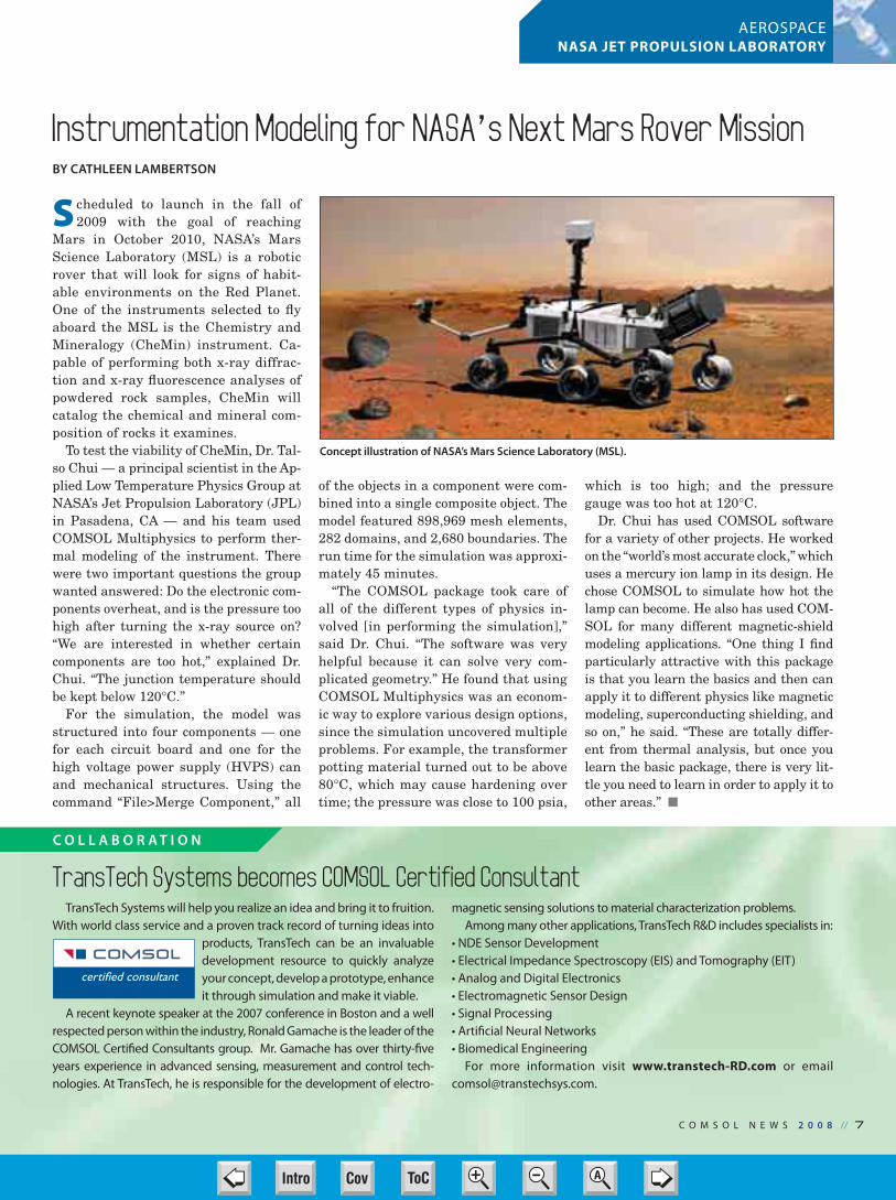
S cheduled to launch in the fall of
2009 with the goal of reaching
Mars in October 2010, NASA’s Mars
Science Laboratory (MSL) is a robotic
rover that will look for signs of habit-
able environments on the Red Planet.
One of the instruments selected to fly
aboard the MSL is the Chemistry and
Mineralogy (CheMin) instrument. Ca-
pable of performing both x-ray diffrac-
tion and x-ray fluorescence analyses of
powdered rock samples, CheMin will
catalog the chemical and mineral com-
position of rocks it examines.
To test the viability of CheMin, Dr. Tal-
so Chui — a principal scientist in the Ap-
plied Low Temperature Physics Group at
NASA’s Jet Propulsion Laboratory (JPL)
in Pasadena, CA — and his team used
COMSOL Multiphysics to perform ther-
mal modeling of the instrument. There
were two important questions the group
wanted answered: Do the electronic com-
ponents overheat, and is the pressure too
high after turning the x-ray source on?
“We are interested in whether certain
components are too hot,” explained Dr.
Chui. “The junction temperature should
be kept below 120°C.”
For the simulation, the model was
structured into four components — one
for each circuit board and one for the
high voltage power supply (HVPS) can
and mechanical structures. Using the
command “File>Merge Component,” all
of the objects in a component were com-
bined into a single composite object. The
model featured 898,969 mesh elements,
282 domains, and 2,680 boundaries. The
run time for the simulation was approxi-
mately 45 minutes.
“The COMSOL package took care of
all of the different types of physics in-
volved [in performing the simulation],”
said Dr. Chui. “The software was very
helpful because it can solve very com-
plicated geometry.” He found that using
COMSOL Multiphysics was an econom-
ic way to explore various design options,
since the simulation uncovered multiple
problems. For example, the transformer
potting material turned out to be above
80°C, which may cause hardening over
time; the pressure was close to 100 psia,
which is too high; and the pressure
gauge was too hot at 120°C.
Dr. Chui has used COMSOL software
for a variety of other projects. He worked
on the “world’s most accurate clock,” which
uses a mercury ion lamp in its design. He
chose COMSOL to simulate how hot the
lamp can become. He also has used COM-
SOL for many different magnetic-shield
modeling applications. “One thing I find
particularly attractive with this package
is that you learn the basics and then can
apply it to different physics like magnetic
modeling, superconducting shielding, and
so on,” he said. “These are totally differ-
ent from thermal analysis, but once you
learn the basic package, there is very lit-
tle you need to learn in order to apply it to
other areas.” �
Instrumentation Modeling for NASA’s Next Mars Rover MissionBY CATHLEEN LAMBERTSON
Concept illustration of NASA’s Mars Science Laboratory (MSL).
TransTech Systems becomes COMSOL Certified ConsultantTransTech Systems will help you realize an idea and bring it to fruition.
With world class service and a proven track record of turning ideas into
products, TransTech can be an invaluable
development resource to quickly analyze
your concept, develop a prototype, enhance
it through simulation and make it viable.
A recent keynote speaker at the 2007 conference in Boston and a well
respected person within the industry, Ronald Gamache is the leader of the
COMSOL Certified Consultants group. Mr. Gamache has over thirty-five
years experience in advanced sensing, measurement and control tech-
nologies. At TransTech, he is responsible for the development of electro-
magnetic sensing solutions to material characterization problems.
Among many other applications, TransTech R&D includes specialists in:
• NDE Sensor Development
• Electrical Impedance Spectroscopy (EIS) and Tomography (EIT)
• Analog and Digital Electronics
• Electromagnetic Sensor Design
• Signal Processing
• Artificial Neural Networks
• Biomedical Engineering
For more information visit www.transtech-RD.com or email
C O M S O L N E W S 2 0 0 8 // 7
C O L L A B O R AT I O N
AEROSPACENASA JET PROPULSION LABORATORY
07-CN NASA JPL 2008.indd 7 3/25/08 1:22:45 PMCov ToC + – ➭
➮
AIntro
8 // C O M S O L N E W S 2 0 0 8
MANUFACTURINGROCTOOL
Mathematical modeling is
going far beyond the R&D
lab and is starting to make a
real difference in manufactur-
ing processes. For instance, it’s
hard to imagine that RocTool’s
primary process, our rapid
composite molding technology,
would be here today without
COMSOL Multiphysics. In fact,
the success story of our company
is linked closely to the capabili-
ties of that software.
The process that makes up
virtually all of our business to-
day did not exist just five years
ago. And it was only with the
help of COMSOL that we were
able to discover, understand and
commercialize our Cage System
technology. Today it would be
virtually impossible to adapt our
process to each client’s require-
ments without the software.
RocTool is an innovative com-
pany that specializes in licens-
ing its rapid molding technolo-
gies for the composites industry.
Its customers include major
automobile manufacturers plus
their Tier 1 suppliers, the air-
craft industry, as well as sports
and leisure companies — all
where lightweight yet strong
composite materials are key
components (Figure 1). The
company does no manufactur-
ing; rather, it helps clients set
up production lines that inte-
grate the Cage System induc-
tive-heating method. With 15 employees
and growing, RocTool last year had sales
near 1.5 million euros, all from the licens-
ing of its patents and in consulting.
Better control of tooling-surface heat
When making composite parts in Resin
Transfer Molding (RTM), a mold must be
hot enough to cure the material, but not
too hot during the injection phase. The
mold generally consists of top and bottom
surfaces separated by a few millimeters.
Traditionally, molding sections are made
of solid metal; these are heated by send-
ing hot oil or water through small shafts
bored through the mold, or by sitting the
mold on a heating plate. This means that
large volumes of metal are being continu-
ously heated and, depending on the appli-
cation and mold, the process can require
20 to 50 kW or more of power for 24 hours
a day, 7 days a week. A complete injec-
tion/curing cycle varies with the
requirements of the material
being formed; for instance, with
a thermoset such as an epoxy
resin it can take 15 to 20 min-
utes at a constant temperature
of 90°C.
We at RocTool knew there
must be a better, faster way. I
learned about COMSOL Multi-
physics’ capabilities during my
PhD work and, when I joined
RocTool five years ago, one of
the first things I did was to tell
engineering management that
we had to have it. This turned
out to be an excellent decision.
With COMSOL, we developed
the Cage System, which we
subsequently patented in 2004.
This method involves surround-
ing both parts of the metal mold
with an induction coil that is
driven by a high-frequency sig-
nal of between 15 and 100 kHz.
Because of skin effects, induced
current stays within the outer
0.1 or 0.2 mm of the mold sec-
tions. The mold has a high
magnetic permeability which
induces strong eddy currents,
and the material’s high resis-
tance results in locally heating
the tooling surface in desired
places. The other conductive
surfaces on the exterior of the
mold are made of nonmagnetic
materials and do not contribute
noticeably to the heating. Heat-
ing of the tooling surface starts
immediately when the coil is activated,
and requires 200 kW or more of power to
quickly get from 40°C to 140°C. As a con-
sequence the heating/cooling cycle drops
to between 2 and 5 minutes (Figure 2).
The Cage System also gives process
engineers much better control of the tem-
perature cycle. For instance, the classical
method to mold material such as resin
epoxies uses a lower constant mold tem-
perature during both injection and cur-
Innovative Molding TechnologyJOSÉ FEIGENBLUM, ROCTOOL, LE BOURGET DU LAC, FRANCE
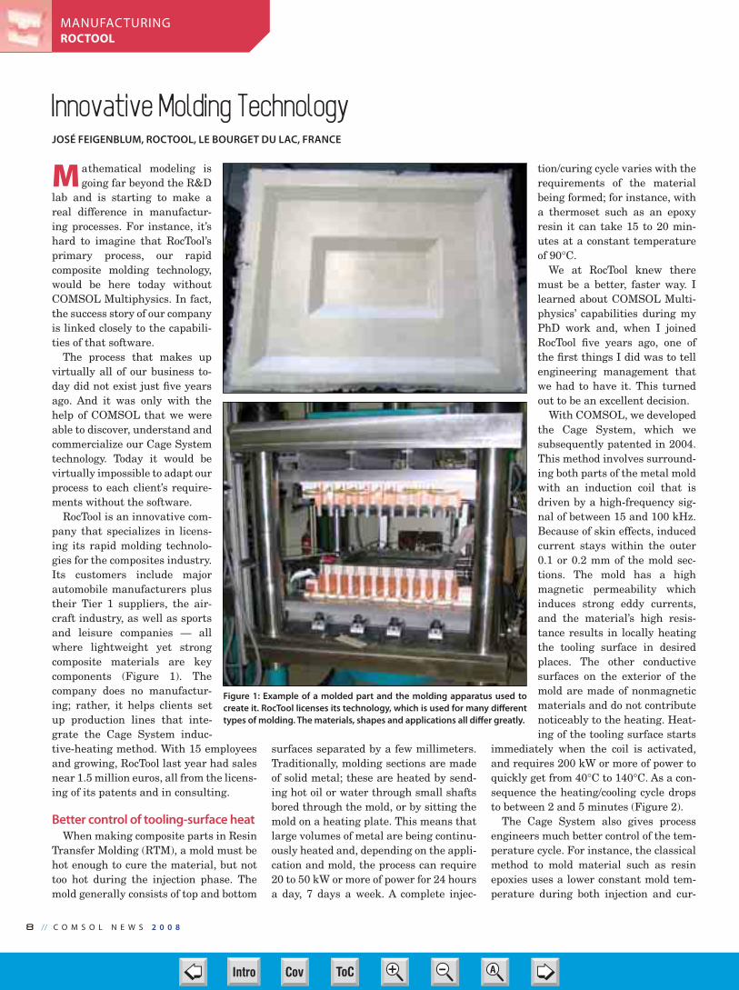
Figure 1: Example of a molded part and the molding apparatus used to
create it. RocTool licenses its technology, which is used for many different
types of molding. The materials, shapes and applications all differ greatly.
08-09-10-CN RocTool 2008.indd 8 3/25/08 1:23:21 PMCov ToC + – ➭
➮
AIntro

C O M S O L N E W S 2 0 0 8 // 9
MANUFACTURINGROCTOOL
ing. This lower mold temperature avoids
cross-linking during injection, but the
curing cycle takes a long time. The Cage
System, on the other hand, preheats the
mold to 40°C so that the epoxy resin has
good viscosity for being injected, and the
temperature can be quickly increased for
the curing stage. In this way, it is pos-
sible to cut cycle times by a factor of two
or three for many processes. Further, the
Cage System is applicable to many mold-
ing processes that require fast heating
and cooling, and it can be used in virtually
all types of molding, such as blow, extru-
sion, injection, or compression molding.
Aproblem with using induction currents
to heat the mold surfaces is the possibility
of hot spots. The mold surface’s shape can
influence the magnetic field and thus the
induced current, and for many shapes it is
possible to see considerable temperature
differences across the tooling surface. The
material being transformed is therefore
not heated homogeneously and a sharp
curve can cause overheating where it is
convex and underheating where it is con-
cave. This is due both to higher current
density on the convex radius and the fact
that heat is concentrated in the area near
the radius. However, with the Cage Sys-
tem, engineers can place surface inserts
with lower magnetic properties in certain
areas to closely regulate the heat distri-
bution and to eliminate hot spots. Model-
ing is an integral part of determining the
placement of these inserts.
Users indicate that while a molding
machine using this process might cost
15 to 20% more than one using classical
methods, manufacturing efficiencies then
lower the cost of the final by 15 to 20%.
For instance, the production of 20,000
automotive roofs using classical methods
requires 2 production units and leads to
a cost of 90 euro/ piece, which decreases
to 45 euro/piece using the Cage System
production unit. This is mostly due to a
drastic reduction in the time cycle — by
a factor 5 in this case (4 min as opposed
to 20 min).
A model for every client
In the composite-molding business
there is no such thing as a standard prod-
uct; each mold must be designed individ-
ually based on the customer’s material
and product specifications. This is where
COMSOL Multiphysics plays a crucial
role. After reviewing the application with
a client, RocTool creates a model that
simulates the magnetic fields, eddy cur-
rents and Joule heating on the molding
surface. The aim of the 3D model is to
define the optimal inductor configuration
and surface layer that creates efficient
and homogeneous heating. We pay close
attention to the selection of materials
and the mold geometry, which we can de-
termine effectively only through simula-
tion. We use the AC/DC Module to first
compute a quasi-static magnetic solution
for the field due to the coil, and then use
those results to find the heat distribution
on the tooling surfaces (Figure 3).
Figure 2: The molding process. The composite material is placed within the mold that then
presses down on the material while induction currents heat the two surfaces of the mold. When
the final shape has been taken, water flows through pipes to cool down the material. The final
shape can then be removed.
Figure 3: The magnetic flux (streamlines) and
temperature distribution (color plot) from
the part shown in Figure 1 (symmetry meant
that only a quarter of the geometry had to be
modeled). The purple lines indicate the posi-
tion of the coils.
08-09-10-CN RocTool 2008.indd 9 3/25/08 1:23:51 PMCov ToC + – ➭
➮
AIntro
1 0 // C O M S O L N E W S 2 0 0 8
MANUFACTURINGROCTOOL
With this model, engineers can de-
termine the optimal size of the coil,
its placement, heating material prop-
erties and the optimized cycle time.
We quickly learn how the number and
placement of the turns in the inductor
coil is crucial for homogeneous heat-
ing. Further, if the inductor is not long
enough compared to the mold, cold ar-
eas can arise on the mold extremities
where the magnetic field density is low-
er. After modeling, RocTool engineers
can tell the client that the process will
result in a given temperature cycle,
that molding will take a given amount
of time, and they can also give a rea-
sonable estimate of what the parts will
cost to manufacture.
Our latest research effort, which we
are still in the process of commercializ-
ing, concentrates on determining how to
best work with self thermally regulating
materials (STRMs) to control hot spots.
These materials are useful because when
they reach their Curie temperature they
become nonmagnetic and thus are no lon-
ger subject to inductive heating. Depend-
ing on the amount and placement of these
materials, we can gain even better con-
trol of the temperature profile over the
tooling surfaces. To model these materi-
als in COMSOL, we create a 3D geometry
and first solve for the magnetic field, then
determine the materials’ temperature.
When these materials reach the Curie
point, we re-run the magnetic field cal-
culations and find the new temperatures.
We perform all this work using a loop
written in COMSOL Script.
CAD Import for a variety of clients
Another important aspect of the soft-
ware is the CAD Import Module, as the
tool designers must work with CAD data
supplied by our clients. A large number
of them, especially those in the auto-
motive industry, work with the CATIA®
CAD system and provide geometry data
in either the IGES or STEP formats.
Work with these imported geometries,
from which the tooling engineers create
the heating surfaces for the mold, is sup-
ported through the CAD Import Module.
Part geometries can sometimes be quite
complex, and the modelers use defeatur-
ing tools to simplify the geometry to make
the modeling more practical. They must
strike a balance between model solution
times and the detail of the results.
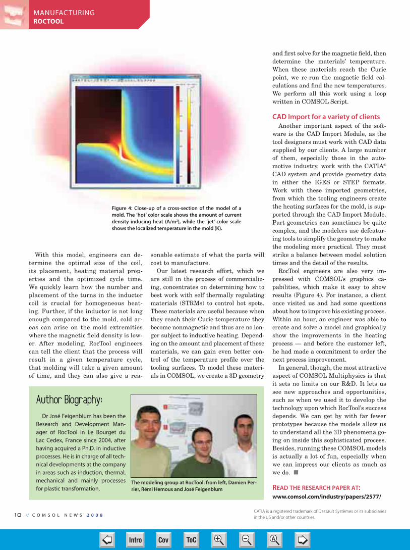
RocTool engineers are also very im-
pressed with COMSOL’s graphics ca-
pabilities, which make it easy to show
results (Figure 4). For instance, a client
once visited us and had some questions
about how to improve his existing process.
Within an hour, an engineer was able to
create and solve a model and graphically
show the improvements in the heating
process — and before the customer left,
he had made a commitment to order the
next process improvement.
In general, though, the most attractive
aspect of COMSOL Multiphysics is that
it sets no limits on our R&D. It lets us
see new approaches and opportunities,
such as when we used it to develop the
technology upon which RocTool’s success
depends. We can get by with far fewer
prototypes because the models allow us
to understand all the 3D phenomena go-
ing on inside this sophisticated process.
Besides, running these COMSOL models
is actually a lot of fun, especially when
we can impress our clients as much as
we do.
READ THE RESEARCH PAPER AT:
www.comsol.com/industry/papers/2577/
The modeling group at RocTool: from left, Damien Per-
rier, Rémi Hemous and José Feigenblum
Figure 4: Close-up of a cross-section of the model of a
mold. The ’hot’ color scale shows the amount of current
density inducing heat (A/m2), while the ’jet’ color scale
shows the localized temperature in the mold (K).
Author Biography:Dr José Feigenblum has been the
Research and Development Man-
ager of RocTool in Le Bourget du
Lac Cedex, France since 2004, after
having acquired a Ph.D. in inductive
processes. He is in charge of all tech-
nical developments at the company
in areas such as induction, thermal,
mechanical and mainly processes
for plastic transformation.
CATIA is a registered trademark of Dassault Systèmes or its subsidiaries
in the US and/or other countries.
08-09-10-CN RocTool 2008.indd 10 3/25/08 1:24:42 PMCov ToC + – ➭
➮
AIntro

Computational analysis of fluid-struc-
ture interactions (FSI) represents a
considerable challenge for most compu-
tational analysis codes. Simple one-way
coupled problems, in which the fluid
pressure deforms a structure but does
not substantially affect the fluid flow
characteristics, can be solved by a variety
of techniques. Solutions to the more com-
plex two-way coupled fluid-structure in-
teractions are more elusive. These occur
when pressure of the flow of fluid deforms
a structure in such a way that the result-
ing deformation alters the flow of fluid.
The two-way coupled approach solves
this problem and produces accurate, time
dependent results.
Through the use of COMSOL Multi-
physics, ACES of Columbus, LLC has de-
veloped practical solutions to realistic FSI
problems across a wide range of applica-
tions in the biomedical, automotive and
petrochemical industries. Examples of
FSI problems in these industries include:
blood flow through flexible systems, char-
acteristic acoustic signatures of valve
components, structural vibration due to
intermittent transient flow through com-
pressors and control of fluid cavitation
around a vibrating structure.
COMSOL Multiphysics has been used
to develop a specialized multiphysics
model describing the response of a vibrat-
ing needle in a liquid.
The vibration of the nee-
dle generates a pressure
wave and causes bending
of the flexible needle.
The FSI solution
couples the continuum
equations of solid me-
chanics with the Na-
vier-Stokes equations
of fluid mechanics.
COMSOL Multiphysics
solves these equations
simultaneously over the
same computational do-
main using an Arbitrary
Lagrangian-Eulerian
formulation (ALE). The
moving mesh capabili-
ties in the ALE formula-
tion of COMSOL allow
a stable solution while
increasing the amounts of needle move-
ment and deformation.
Solutions of this type can quantify
the influence of key design variables of
the system. For example, the operating
stress experienced by the needle, stream
lines of the fluid flow, and the acoustic
sound pressure levels developed (see
Figure 1).
The results of fully coupled FSI analy-
ses have allowed ACES to resolve perfor-
mance issues with new products prior to
mass production, significantly reducing
the time and cost of new product develop-
ment and manufacture.
This work was performed by Dr. S.P.Yushanov, Dr. J.S. Crompton, and Dr. K.C.Koppenhoefer using COMSOL Multiphys-ics. For more information please contact:K.Koppenhoefer,ACES of Columbus,750E Cross Pointe Rd, Columbus, OH 43230, or visit www.acescolumbus.com.
Fluid-Structure-Acoustic InteractionsBY DR. S.P. YUSHANOV, DR. J.S. CROMPTON, AND DR. K.C. KOPPENHOEFER, ACES OF COLUMBUS, LLC
Figure 1. Sound pressure levels developed from two needle designs.
These designs seek to maximize local pressure levels and minimize
pressure at a specified distance.
Best Paper and Best Poster Awards — COMSOL Conference Boston and Grenoble 2007Boston Best Paper Awards
• Acoustic Transparency of Non-homogeneous Plates (with repeating
inclusions) using Periodic Structures Methodology, Anthony Kalinowski,
Naval Undersea Warfare Center, Newport, RI
• Geometrical Optimization of Pyrophosphate Concentration in Ther-
mosequencing Platform for DNA Sequencing, Hessaam Esfandyarpour,
Stanford University, Palo Alto, CA
• A Model of Direct Thermal Printing, W. T. Vetterling, ZINK Imaging, Inc.,
Waltham, MA
Boston Popular Choice Best Poster Award
• Magnetic Particle Motion in a Gradient Field, Usha K Veeramachaneni,
West Virginia University, Morgantown, WV
• Voltammetric Performance of Nanometer Interdigitated Electrodes,
Guigen Zhang, The University of Georgia, Athens, GA
Grenoble Winners
• Catalyst Degradation in PEM Fuel Cells — Modeling Aspects, Vaivars
Guntars University of the Western Cape — South African Institute of Ad-
vanced Material Chemistry, South Africa
• Coupled Electro Thermal and Fluid Dynamical Simulation of Axial
Flux Permanent Magnet, Synchronous Machines, Marignetti Fabrizio,
Universitá degli Studi di Cassino, Italy
• 3D Semiconductor detectors for medical imaging, Ruat Marie, CEA
Grenoble, France
• Structural Shape Optimization Using Moving Mesh Method, Liu
Zhenyu, Universität Freiburg, Germany
C O M S O L N E W S 2 0 0 8 // 1 1
MANUFACTURINGACES
11-CN Aces Editorial 2008.indd 11 3/26/08 12:36:15 PMCov ToC + – ➭
➮
AIntro

1 2 // C O M S O L N E W S 2 0 0 8
MANUFACTURINGPHILIPS
Behind your clean, close shave there
is an enormous amount of high tech-
nology, even in electric shavers that have
been around for decades. Philips DAP is
working with new materials for, among
other components, the shaving cap that
acts as a shell around the rotating cutter.
On its next-generation shavers expected
to reach the market in a couple of years,
Philips is starting to use multiphysics
modeling to optimize the process used to
manufacture these caps.
In the manufacturing process, Phil-
ips first forms raw caps from transfor-
mation-induced plasticity (TRIP) steel.
Because these are too thick and do not
have the required precision shape, fur-
ther manufacturing is required. For
the low-end shaver range, Philips used
electrical discharge machining (EDM) to
finish the low-end shaver caps, but it re-
quired costly and regular replacement of
the component electrodes and is there-
fore not applicable for complex shapes.
High-end shavers also work with three
cutters instead of one, so the cap has
a much more sophisticated shape that
requires a more complex manufactur-
ing process (Figure 1). Philips turned
towards electrochemical machining
(ECM) to enable more complex shapes.
Nowadays, the demand of more close-
ness requires improved process under-
standing. Computational simulations,
rather than running costly experiments
throughout the entire evaluation and
optimization process can provide this
vital information.
ECM consists of the managed electro-
chemical dissolution of an anode (the
cap) by passing current between it and a
pre-shaped cathode (the tool). At the cap
surface, metal is dissolved into metal-
lic ions by an electrochemical reaction.
Placing the tool — whose shape is not al-
tered by the reaction — and setting the
applied voltage results in a cap with the
desired accurate shape.
Electrolyte flows between the cap and
tool to remove metallic ions as well as a
gas that evolves on the cap through a side
reaction. The presence of this gas also
contributes to the electrolyte’s electri-
cal resistance, and, along with the cap’s
changing surface area, the varying resis-
tance must be compensated for by adjust-
ing the system’s voltage. A mass balance
must also be considered to describe the
electrochemical kinetics at the electrodes
as well as adjust for material-based prop-
erties such as density in the fluid flow.
Here ECM works with high currents
in thin materials and small electrolyte
channels, which leads to high tempera-
tures and even boiling if electrolyte flow
is not adequate. This, along with the fact
that the cap’s structure also changes
over time and is influenced by the high-
pressure electrolyte flow, results in sig-
nificant changes in the cap’s structural
integrity, where phenomena such as
spring-back can occur. High tempera-
tures also affect density in the fluid flow.
In all, Philips has a complex multiphys-
ics problem to investigate (Figure 2).
These highly interrelated effects make
it virtually impossible to optimize the
process through experimentation alone.
Electrochemical Machining in Appliance ManufacturingTo find the most efficient way to manufacture the caps for electric shavers, engineers at Philips use
multiphysics modeling to study the best balance of process parameters.
DR. IR. REDMER VAN TIJUM, ROYAL PHILIPS ELECTRONICS NV, DRACHTEN, THE NETHERLANDS
Figure 1: Picture of a next-generation
Philips shaver. The three-cutter system
can be seen as well as the required
precision in the manufacture of the
shaver caps.
12-13-CN Philips 2008.indd 12 3/25/08 1:26:07 PMCov ToC + – ➭
➮
AIntro

C O M S O L N E W S 2 0 0 8 // 1 3
MANUFACTURINGPHILIPS
Computational simulations were re-
quired, and Philips employed COMSOL
Multiphysics. This package could handle
all the interrelated physics while provid-
ing the ability to couple these physics. It
also allowed models that would be easily
understood by all people in the modeling
and manufacturing processes.
To model this process, Philips needed
to consider the physics of the electrical
current. COMSOL Multiphysics contains
a modeling interface for this, where elec-
trochemical kinetics can be freely en-
tered directly to simulate the reactions
at the cap-electrolyte interface. Further-
more, COMSOL’s interface also provides
high flexibility whereby users can de-
scribe the conductivity that varies due
to the presence of gas bubbles and heat.
This was all then coupled directly to oth-
er modeling interfaces that describe the
fluid flow (non-isothermal flow) and heat
transfer (convection and conduction),
where a source term in the heat trans-
fer equations depends directly on the
electrical current. An equation was also
entered in the density term of the fluid-
flow modeling interface to represent the
effects of temperature and gas-mixture
makeup. To save computational memory,
heat flux was represented at the tool and
cap interfaces with the electrolyte in or-
der to simulate their energy storage ca-
pabilities.
The cap’s structural geometry was
also considered with respect to its effect
on the other physics. The shape of the
pre-formed cap was imported and could
easily be updated during the modeling
process based on intermediate model
results. Furthermore, a special ‘moving
mesh’ modeling interface was utilized
for simulating the changing shape of the
cap when it was coupled to the electro-
chemical reactions that simulated the
dissolving TRIP steel. This resulted in
an adequate description of the electro-
lyte channel and fluid flow.
With this model (Figure 3), Philips is
well on the way to generating a manu-
facturing process for these new caps, to
improve closeness. Validation studies
are in progress, and then these models
will become the driving force for improv-
ing the manufacturing process and the
production lines.
Figure 3: Results from a 2D model of a cut through the electrolyte channel between a shaver cap (top)
and the tool (bottom). Electrolyte flows from right to left. Shown is the gas concentration (color plot)
and velocity field (arrow plot). Noticeable is the effect that flow has on gas distribution as well as the
accelerating effect that the gas impinges on the flow. Shown in the above plot is the distribution of cur-
rent density along the cap’s entire surface where peaks correlate to bends in the geometry and areas of
greater dissolution.
Figure 2: The various physics couplings in the multiphysics process that Philips must consider when
modeling electrochemical machining (ECM).
Structural Analysis and
Electrode Geometry
Energy Balance
Fluid Flow
Affects heat capacity
Affects electrochemical kinetics
Mass Balance
Affects densityDissolves material
Po
sition
of e
lectro
de
s
Flu
she
s g
as
Convection
Charge Balance
Co
nve
ctio
n
Electrolyte channel
Affects
con
du
ctivity
Ele
ctro
lyti
cally
pro
ducedgas
De
nsi
tye
ffe
cts
Pressure forces
Act
sas
he
at
sou
rce
/sin
k
Generates heat
Ele
ctro
chem
ical re
actions
Ther
ma
l-st
ruct
ura
le
ffe
cts
12-13-CN Philips 2008.indd 13 3/26/08 12:38:37 PMCov ToC + – ➭
➮
AIntro

1 4 // C O M S O L N E W S 2 0 0 8
MANUFACTURINGPEM
G iven the scarcity and price develop-
ments of today’s metals, virtually all
of them can be counted as being ‘precious’.
As a result, electroplating firms such as
PEM always look for ways to reduce the
amount of metals that are consumed as
part of a process. Thanks to studies con-
ducted using COMSOL Multiphysics, we
have made significant advances, often in-
cluding savings between 10% and 30% of
the metal we deposit during electrolysis.
Components on reelsWith sales of roughly 20 million euros in
2007, PEM is heavily involved in treating
and finishing surfaces, and our specialty
is reel-to-reel electroplating. The cus-
tomer supplies a reel, which can be from
several hundred to several thousand me-
ters, and whose tape holds a continuous
series of metal parts such as connectors
for electronics systems. At our facilities,
we unwind the tape or carrier strip from
these reels, and send it through a sophis-
ticated process consisting of cleaning,
plating and rinsing stages. This happens
at speeds from 1 to 20 m/min (Figure 1).
During the metal-plating stage, the
tape passes through a reacting cell that
is continuously replenished with electro-
lyte. The tape is made cathodic through
contact to a voltage source, and the elec-
trolyte completes the electrical circuit to
anodes in the plating cell.
Getting a uniform plating layer is not
simple. Consider that more metal tends
to migrate towards the edges because if
the tape (the cathode) is standing on end
and the anodes are to its sides, the shape
of the electric potential field follows the
tape — up one side, around the top, and
down the other side. Spikes in the cur-
rent-density distribution occur where the
tangential gradients for potential con-
tribute, along with the normal gradients,
to the overall ionic transport of species to
and from the electrode surface (see blue
trace in Figure 2). These are more com-
monly known as edge effects.
PEM’s answer is to design a shield, a
type of insulating screen or tray through
which the tape travels as it passes through
the plating reactor. Made with insulating
materials that are chemically compat-
ible with the bath, the shield is shaped so
the lines of electric potential essentially
run parallel along the entire width of the
tape, and the gradient to the tape surface
is even. The red trace in Figure 2 shows
the benefits of adding such a shield.
Shield design without prototypesThe shield’s shape varies with the com-
ponents on the reel, the plating material
and its thickness, electrolyte concentra-
tion, and tape traveling speed. Develop-
ing shields experimentally can require
multiple time-consuming prototypes, so
PEM started to use COMSOL Multiphys-
ics to help us better understand the un-
derlying phenomena and thereby come
up with an appropriate shield for each
process. These days, we are generally
successful on the first try.
The multiphysics model accounts for
several effects: conductive media for the
electrical current, Navier-Stokes for the
electrolyte flow, and electrokinetic flow
to simulate the transport of species. For
this, we use the Chemical Engineering
Module along with the COMSOL Multi-
physics modeling environment.
Reduced Metal Consumption in Electroplating Saves Big MoneyBY PHILIPPE GENDRE, PEM, SIAUGUES, FRANCE
Figure 1: Factory floor with a series of reel-to-reel electroplating units. Reels of solid or stamped metal plates are passed through the electroplating units, and metal is deposited over the whole or sections of the tape according to the application of electric current and the placement of shields.
Author Biography:Philippe Gendre is Head of R&D at PEM in Siau-gues, France. He earned his Ph.D. in material chemistry from Pierre et Marie Curie (Paris VI) University. He has been working at PEM since 1997 on R&D topics re-lated to developing new processes and materials for electrolysis.
14-15-CN PEM 2008.indd 14 3/25/08 3:13:46 PMCov ToC + – ➭
➮
AIntro
C O M S O L N E W S 2 0 0 8 // 1 5
MANUFACTURINGPEM
Save even more material
We have successfully designed shields
that handle most of the types of products
we run through our process. Our next
goal with COMSOL is to examine the ef-
fects of limiting currents so as to design
our reactor cell with high fluid veloci-
ties near the cathode surface and thus
increase process throughput. If you can
replenish the metal ions better, you can
raise the current density and thus pro-
duction (Figure 3).
Furthermore, the potential must be
uniform throughout, so that there are
no local secondary reactions such as the
electrolyte electrolyzing to create hydro-
gen gas, leading to depleted areas of met-
al deposition or “tape burns.” Thus, the
tradeoff is to run the process as quickly
as possible but where the entire surface
is just below the current-limiting densi-
ty. This type of modeling is particularly
challenging because of the reactor size,
as well as lateral and vertical oscillations
due to tape movement with respect to the
electrolyte injection holes. Yet, accurate
predictions will have a major influence
on future reactor designs.
One final aspect is that modeling is
only a part of my job. Previously I had no
real modeling experience, and my initial
problems were not in learning COMSOL,
as the software is very well designed and
support is quite efficient, but rather mas-
tering the underlying physics. Yet COM-
SOL allowed me to understand the phys-
ics quickly and I came to appreciate that
you don’t have to be a modeling expert to
make good use of it. Anyone who is suf-
ficiently curious and motivated can have
great success.
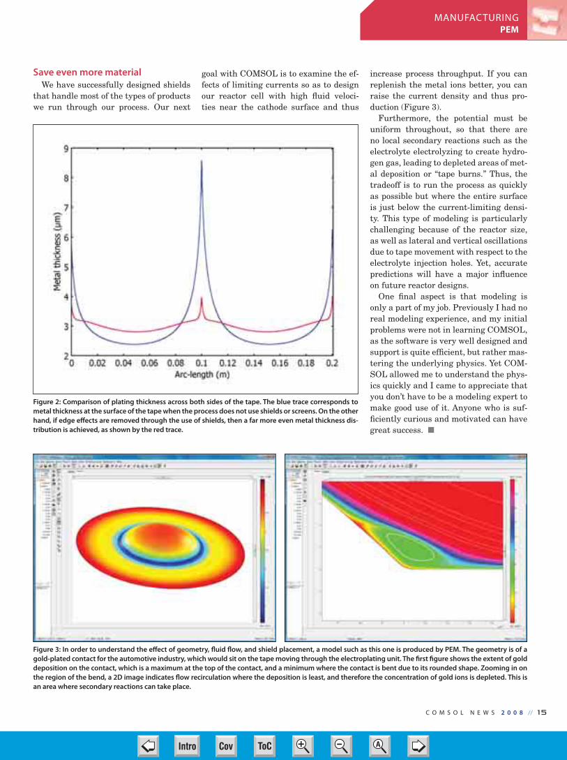
Figure 2: Comparison of plating thickness across both sides of the tape. The blue trace corresponds to
metal thickness at the surface of the tape when the process does not use shields or screens. On the other
hand, if edge effects are removed through the use of shields, then a far more even metal thickness dis-
tribution is achieved, as shown by the red trace.
Figure 3: In order to understand the effect of geometry, fluid flow, and shield placement, a model such as this one is produced by PEM. The geometry is of a
gold-plated contact for the automotive industry, which would sit on the tape moving through the electroplating unit. The first figure shows the extent of gold
deposition on the contact, which is a maximum at the top of the contact, and a minimum where the contact is bent due to its rounded shape. Zooming in on
the region of the bend, a 2D image indicates flow recirculation where the deposition is least, and therefore the concentration of gold ions is depleted. This is
an area where secondary reactions can take place.
14-15-CN PEM 2008.indd 15 3/25/08 1:27:24 PMCov ToC + – ➭
➮
AIntro

1 6 // C O M S O L N E W S 2 0 0 8
BIO-MEDICALMEDRAD
Computer modeling has proven its
value throughout the design, devel-
opment, and deployment of new prod-
ucts. Such is the experience of John
Kalafut, a principal research scientist
in MEDRAD’s Innovations Group (In-
dianola, Pennsylvania) who comments,
“COMSOL Multiphysics has accompa-
nied me throughout my career at ME-
DRAD, starting with systems engineer-
ing and today in R&D, even for products
that won’t be available for many years.”
Kalafut’s experiences as a medical engi-
neer show how multiphysics modeling is
useful for solving an exceptionally wide
range of problem.
MEDRAD, with sales of roughly $500
million, manufactures, sells, and servic-
es medical devices for diagnostic imaging
and therapy in three main areas: cardio-
vascular diagnosis, magnetic resonance
imaging (MRI), and computed tomogra-
phy (CT). The company has 1700 employ-
ees worldwide, and physicians around
the world use the company’s products
for more than 20 million medical proce-
dures each year. One of the company’s
core competencies is intravascular fluid
delivery such as supplying exact doses of
medicine or contrast agents. The Innova-
tions Group investigates novel technolo-
gies, business opportunities, and clinical
applications to continue the company’s
>15% growth rate.
Five engineers in the company use
COMSOL software for a variety of tasks.
Comments Kalafut, “COMSOL Multi-
physics is a natural choice to support us
during the investigation of concept feasi-
bility, IP due diligence, and in research.
This is a very powerful tool for the corpo-
rate biomedical engineer in research and
development. Its true multiphysics capa-
bilities mean that ‘the sky’s the limit’ in
terms of what we can tackle. COMSOL
Multiphysics allows for the quick inves-
tigation of complex interactions — and a
very affordable price.”
From a modeling perspective, much of
the firm’s research deals with the most
efficient yet safest way to deliver diag-
nostic fluids into a patient’s body. And
while fluid dynamics plays a crucial role
in such studies, these models sometimes
also involve heat transfer, electrostatics,
chemical engineering, electro-
magnetics, and other physics.
Finding the bestpeak-enhancement curve
Speed of delivery plays an in-
creasingly important role in im-
proved CT scanners that allow for
the acquisition of volumetric scans
of the entire body in just seconds.
To achieve the superb diagnostic
images possible with modern CT
scanners, the injection and deliv-
ery of the contrast material must
be synchronized with the imag-
ing procedure. One benefit of new
CT scanners is that because the
imaging takes a shorter amount of time,
the total dose of contrast material can be
reduced. The timing window is short, but
in that time doctors want to make certain
they have good insight into how the mate-
rial travels throughout the body.
Fast injections alter the enhancement
profile and, because the flow is transiting
so quickly through the vasculature, the de-
livery peak is sometimes not well synchro-
nized and the patient must be re-injected
and scanned again. In addition, each pa-
tient presents a different flow profile (time-
density curves), which complicates rational
material-delivery schemes. The key ques-
tion becomes how much contrast material
must you inject to get good images of the
blood vessels and the heart? At what rate?
How long should the injection last?
As is the case with many systems devel-
oped at MEDRAD, here a major goal is to
get the maximum amount of contrast ma-
terial into the bloodstream and heart as
quickly as possible. Researchers want to
study the dynamic forces that arise from
the insertion of a viscous fluid through a
tube at rates from 0 to 6 or 7 ml/sec.
To address these questions, the compa-
ny is developing smart injection systems
where a doctor first performs an identifi-
cation injection, and the system then de-
termines the proper amount of contrast
material. In the research and feasibil-
ity phase of this technology, a model of
the human body would be preferable to
benchtop in-vitro investigation or animal
models. However, it would be impractical
to do a full finite-element model of the
Faster, Safer Delivery of Therapeutic SubstancesBY PAUL G. SCHREIER
Figure 1: A simplified model of the circulatory system from the point of entry for the contrast material lead-ing to the heart. With this exploratory model, the engineers can determine which conditions give the optimal distribution.
Dr John Kalafut MEDRAD’s Innovations Group
16-17-CN Medrad 2008.indd 16 3/25/08 3:12:51 PMCov ToC + – ➭
➮
AIntro

C O M S O L N E W S 2 0 0 8 // 1 7
BIO-MEDICALMEDRAD
entire body, so Kalafut and his team con-
centrated on the vessels going from the
point of injection to the heart, so as to de-
termine what happens to the drug on its
way there (Figure 1).
They used COMSOL Multiphysics and
the Chemical Engineering Module to bet-
ter understand the early-time dynamics
of the injection event. They coupled the
Navier-Stokes application mode with the
Convection & Diffusion application mode
to gain insight into the distribution of the
contrast agent through the peripheral vas-
culature into the heart. The early phase
of the contrast’s distribution in-vivo is dif-
ficult to determine non-invasively and is
crucial for understanding the dynamics of
contrast injection and propagation.
Knowledge gained by numerical model-
ing and simulation lends credence to as-
sumptions made in global, compartmental
models of the contrast material distribu-
tion after injection. One example of this
model’s application is in understanding
the transit time from the injection site,
typically a large bore angiocath needle in-
serted into an arm vein, to the heart. In
some patients, due to possibly diseased
venous systems, blocked veins, or even
the position of the arm during injection,
not all of the injected contrast material ar-
rives as a well-defined bolus. Rather, the
contrast material can become dispersed
and arrive over a period of different times.
Such a situation makes predictive control
and contrast material delivery difficult, if
not impossible to conduct.
The COMSOL models are playing a role
in discovering which factors influence the
dynamics of the contrast material. Be-
cause it is injected at rates much higher
than typically encountered in healthcare
(2-8 ml/s), an understanding of the pro-
cesses at the injection site is also an area
ripe for investigation with COMSOL Mul-
tiphysics. Figure 2 displays a 2D simula-
tion depicting the injection of highly vis-
cous fluid into a large bore “blood vessel.”
The results from this simulation are cou-
pled with a material and physical model
to better understand the relationship
between injection rate and the dynamics
at the needle-puncture site. This knowl-
edge could ultimately aid clinicians when
assessing the likelihood of an injection
site failing (an uncommon but aggravat-
ing situation) during the administration
of contrast material. This model leads to
better use of the material, better scans,
and better diagnosis.
Shielding a communications link
One of the company’s first serious ex-
periences with finite-element modeling
— and where they found that COMSOL
Multiphysics makes modeling easy —
came when fixing a problem that arose in
an upgraded MRI contrast-injection sys-
tem. That system uses an infrared link to
communicate between the injection stand
in the treatment room and the operator
panel in a glassed-in control room (Figure
3a). Component obsolescence — an inte-
grated circuit phototransducer taken out
of production — required redesign of the
communications link. The replacement
part, however, brought with it some new
problems; it was failing because it was
more susceptible to electromagnetic inter-
ference from the MRI scanner and volt-
ages inherent in the system.
The task then became one of determin-
ing how to reduce the effects of the elec-
tromagnetic fields on the phototransduc-
er. Using COMSOL Multiphysics, Kalafut
quickly replicated the problems that ser-
vice engineers saw and concluded that a
shielding structure around the transceiv-
er structure would be a quick, cheap solu-
tion (Figure 3b). He explains, “we had to
determine how thick the shielding should
be and what shape it should have to do an
adequate job, but also be as small as pos-
sible and fit in the existing equipment.”
Using COMSOL Multiphysics he set up a
parametric solver to examine various ge-
ometries. “This approach saved us weeks
of benchtop testing and technician time
in building prototypes. In addition, the
3D plots we generated were quite useful
in communicating the value of modeling
with other engineers and with our man-
agement, who thereby first came to appre-
ciate the value of virtual prototyping.”
READ THE FULL ARTICLE AT:www.comsol.com/stories
Figure 2: 2D model of a contrast material mixing
with blood that allows for investigations of the
dispersion of the material.
(Below) Figure 3b: The COM-
SOL Multiphysics model of a
phototransducer along with
its shielding. The results show
the E field around the final ge-
ometry. The goal was to shield
the openings from an external
E field greater than 20 V/m.
(Above) Figure 3a: An MRI contrast-injection
system consisting of a remote control panel
that interfaces to the injection head located in
the treatment room through a wireless link. A
new phototransducer experienced electromag-
netic interference and required shielding that
was optimized using COMSOL Multiphysics.
16-17-CN Medrad 2008.indd 17 3/25/08 1:28:32 PMCov ToC + – ➭
➮
AIntro

1 8 // C O M S O L N E W S 2 0 0 8
MATERIALSZINK IMAGING
Z INK — Zero Ink — technol-
ogy prints full-color digital
images without cartridges or rib-
bons. ZINK renders images using
a single thermal print head that
passes over a coated medium in-
fused with layers of dye crystals.
Using timed heat pulses and tem-
peratures, ZINK melts these crys-
tals to release colors that then
combine to produce photographic-
quality images.
The ZINK system consists of
a thermal print head, the me-
dium moving beneath the print
head, and a rotating platen. The
interplay between the mechan-
ics, the thermal effects, and the
chemical layers of the media
structure is inherently a multiphys-
ics problem. We used COMSOL Multi-
physics to develop a model framework
for direct thermal printing and applied
the model to the ZINK media, demon-
strating its ability to produce full-color
photographic-quality images in a direct
thermal printing process.
ZINK System Components
The ZINK print head is a linear ar-
ray of heating elements, usually 300-600
per inch, sitting on an insulating glass
bump that rides on a ceramic substrate
attached to an aluminum heatsink (see
Figure 1). The print medium is a layered
structure made of three dye layers, two
dye-separating layers, and a number of
protective layers.
In our simulation, the medium was a
single, uniform sheet with mechanical
and thermal properties characteristic of
the plastics used. We drew common ma-
terial properties from the COMSOL Ma-
terial Library and the rest from manu-
facturers, in-house measurements, or
resources like MatWeb.
The platen is a rubber-coated roller
that presses the print medium against
the heating elements. Since the heaters
are on a curved glass surface and the me-
dium is flat, it is a function of the rub-
ber to promote “wrapping” of the medium
around the heaters, thus ensuring good
thermal contact. The moving medium and
platen carry heat away from the printing
region, providing some additional cooling
to the print head.
Models to Dye For
We used multiphysics modeling to
model the mechanical and thermal be-
havior of our direct thermal printing
process and to postprocess the data.
The mechanical simulation investigat-
ed the compressive contact between the
platen and the print medium as well as
between the medium and print head. To
avoid interpenetration of these compo-
nents, we used the “contact pairs” fea-
ture of the Structural Mechan-
ics Module.
Since we simulated a single
heater of the print head, the me-
chanical constraint at the sides
would be zero displacement nor-
mal to the boundaries. COMSOL
enabled us to conserve memory
by setting the material proper-
ties to be orthotropic with a Pois-
son ratio of zero in the normal
direction, which had the effect of
maintaining fixed walls.
Our thermal simulation sub-
jected the structure to periodic
thermal pulsing of the heater ele-
ments. One problem was the thin
layer of air in the vicinity of the
contact between the heating ele-
ment and the medium, which can develop
poor mesh quality under compression.
Model set-up tools let us omit this air
layer and use extrusion coupling to com-
municate the surrounding material sur-
face temperatures and positions across
the gap. This allowed independent evalu-
ation of heat flow through the layer.
Another concern was that both the me-
dia and platen move and transport heat.
COMSOL helped us with this by letting us
apply a linear convective term with the ve-
locity of the medium and a cylindrical con-
vective term with the velocity of the plat-
en. To represent the medium entering the
printer at ambient temperature and leav-
ing warmer, we set a fixed-temperature
boundary condition at the entrance and a
convective boundary condition at exit.
With these features in place, we ran a
time-dependent thermal simulation with
a pulsing heat source on the compressed
geometry. We then processed our solution
with COMSOL Script.
Colorful Postprocessing
Our main interest was the tempera-
tures in a crystal dye layer a fixed dis-
tance below the heated medium’s sur-
face, so we traced a time history of the
temperature at points in the layer fixed
A Model of Direct Thermal PrintingMultiphysics helps researchers make full-color direct thermal printing a reality.
BY WILLIAM T. VETTERLING, ALEXEI AZAROV, BRIAN BUSCH, AND CHIEN LIU, ZINK IMAGING , MASSACHUSETTS, USA
Aluminum Heat Sink
Ceramic SubstrateMedia
moves tothe Left
Glass
Media
Rubber
Steel
PlatenRotates
Author Biography:William T. Vetterling is a Research Fellow and
Director of the Image Science Laboratory for
ZINK Imaging, Inc., Alexei Azarov is Senior
Scientist and Brian Busch and Chien Liu
are Distinguished Scientists. To see a brief
movie showing the COMSOL simulation of
the time development of heat flows, go to:
www.comsol.com/comsolnews/movie.
Figure 1: Model geometry showing the features of the ZINK print head.
18-19-CN Zink 2008.indd 18 3/25/08 1:29:06 PMCov ToC + – ➭
➮
AIntro

C O M S O L N E W S 2 0 0 8 // 1 9
MATERIALSZINK IMAGING
to the medium. Since we used a convec-
tive term to simulate the media motion,
our results referenced points fixed in the
global coordinates.
Armed with the temperature and time
history of every point in the layer, we used
a “media model” to determine the opacity
of the dye at each point in the medium.
Here, we considered a so-called “amor-
phochromic” dye developed for ZINK that
consists of colorless crystals that become
colored upon melting. Since a point in the
medium heated above a crystal’s melting
point gets colored, applying the media
model meant comparing the temperature
history of each point to a threshold melt-
ing temperature.
The surface plot in Figure 2 shows the
temperatures in the components follow-
ing a thermal pulse and as the system
cools to the heat-sink temperature as the
heated media exits the printing region.
It’s apparent that the print medium car-
ries away heat, cooling the center of the
heater, and that the platen also carries
away heat.
Post-processed data shows the maxi-
mum temperatures reached by points in a
plane below the medium’s heated surface
(see Figure 3). If you place a layer of dye
crystals at these points and heat it, you
get a regular array of colored dots. If you
apply pulses of higher energy, tempera-
ture peaks rise and exceed threshold tem-
peratures over a wide area,
producing larger dots, in-
creased color density, and
even a layer of solid color.
Our simulations showed
us how the temperature
peaks diffuse away from
the heat source. A compari-
son of the peak tempera-
tures at various planes of
the media indicated that
we could produce bichrome
images by intermixing
short, high-power pulses
and long, low-power pulses
to melt crystals at different
layers and with dissimilar
melting points. With this
knowledge, we knew we
could position three dye layers to make a
full-color medium and obtain photograph-
ic-quality images with one pass of the me-
dium under the thermal print head.
Future Considerations
As a component of our ZINK thermal
printing development, we make frequent
use of COMSOL Multiphysics tools. Mov-
ing from product invention to product de-
velopment, and then to manufacturing, we
have touched on many engineering fields
— mechanical, thermal, chemical, and flu-
id dynamics. The combination of all these
fields in a single approachable tool with
a single user interface has significantly
lowered the barriers to the use of model-
ing as a daily tool rather than a special
enterprise.
In the future, we will, of course, refine
our models and use optimization to find
the most favorable material properties for
extending our color palette. As we enter
the manufacturing phase of our project,
in which we work with high-speed com-
mercial coaters and driers, the additional
capabilities of the Chemical Engineering
Module in fluid dynamics and process de-
sign become very attractive as possible
additions to our toolset. Beyond that, our
modeling will be guided by the imagina-
tion of our customers!
CONTACT INFORMATIONZINK Imagingwww.zink.com
MatWebwww.matweb.com
Figure 2: Temperature profile following a heat pulse. The color indi-
cates temperature, with a scale going from 273 K to 315 K.
Figure 3: A surface plot showing the maximum
temperatures reached at points in a 2D plane ly-
ing 3 microns below the heated surface medium
after the medium was heated with 3 ms pulses,
spaced by 33 ms. The temperature at the peaks is
436 K (163° C).
William Vetterling (second from right) Research Fellow and Director of the Image Science Lab at
ZINK Imaging with, from left to right team members Alexei Azarov, Chien Liu, and Brian Busch.
Vetterling, Busch, and Liu are among the co-inventors of the ZINK technology.
18-19-CN Zink 2008.indd 19 3/25/08 1:29:44 PMCov ToC + – ➭
➮
AIntro

While setting up the gov-
erning equations, geom-
etry, and mesh consumes the
most simulation time, usually
little time or effort is devoted
to obtaining accurate material
properties. Frequently, scien-
tists and engineers obtain ma-
terial data from a handbook or
web site, which often provide
limited data. For example,
these resources typically do not
specify the test and material
conditions, and a reference to
the original data source is not
provided. It is common to use
data at room temperature in
a simulation because elevated
temperature data could not be
found. However, the effects of
temperature on a given mate-
rial property can be quite large
and ignoring the temperature
effects can lead to erroneous and mis-
leading simulation results.
Faster model set-up using
the Material Library
Finding the right material properties
to use in simulations can be time-con-
suming and expensive. The best method
is to measure the properties you need on
an actual sample of the material. Often,
however, this is not possible, as material
tests can cost tens of thousands of dol-
lars and take several weeks if not longer
to complete.
In light of these practical limitations,
users of COMSOL can
now turn to the Mate-
rial Library for access
to 2,500 materials, all
of which fully integrate
into the COMSOL
Multiphysics model-
ing and simulation en-
vironment. This new
product provides a da-
tabase of temperature-
dependent material
properties that can be
added to your models
at the click of a button.
Even if the material
is not available at the
exact conditions you
are using it, physical
properties can be es-
timated from similar materials.
For example, if your copper alloy
does not match a material in the
database exactly, you can select
one that is as close as possible in
composition, its heat treatment,
or some other relevant aspect.
A thermal stress study
An example of a surface
mounted resistor* (Figure 1)
demonstrates the importance
of temperature dependence and
material plasticity on analysis
results. Electrical current flow-
ing through the resistor leads
to energy dissipation which
results in an increase in tem-
perature. Electrical and there-
fore thermal cycling can lead
to cracks propagating through
the solder joints, resulting in
premature failure. The failure
is caused by the difference in thermal
expansion coefficient between neighbor-
ing materials. A multiphysics simulation
would consider heat transport, along
with structural stresses and deforma-
Application Brief:Temperature Dependent Material PropertiesBY JOHN SELVERIAN, JAHM SOFTWARE, INC. , MASSACHUSETTS, USA
Figure 2. Temperature dependence of the yield strength of the materials.
Author Information:John Selverian, JAHM Software, Inc., has been
involved in materials science for almost thir-
ty years. He received his B.Sc. in Metallurgy
in 1983, and then his M.Sc. (1985) and Ph.D
(1988) in Materials Science and Engineering
from Lehigh University in Bethlehem, PA.
Dr Selverian started building his Material
Properties Databases (MPDB) in 1998 when
he was involved in high-temperature mate-
rials research. During the subsequent years,
he has produced more than 20 papers and
other publications, two US patents and one
European patent.
Figure 1. Depiction of the surface resistor problem. The resistor is made
from aluminum oxide (Al2O
3).
20 // C O M S O L N E W S 2 0 0 8
MATERIALSJAHM SOFTWARE
20-21-CN Selverian 2008.indd 20 3/25/08 1:30:30 PMCov ToC + – ➭
➮
AIntro

tions. In this case, the
resistor body is modeled
using aluminum oxide
(Al2O
3) as the material,
while the termination
is made from silver, the
solder from the Sn-4Ag
alloy, and the circuit
board from FR-4. Four
different simulations are
performed using combi-
nations of room tempera-
ture versus temperature-
dependent material data
with elastic versus elas-
tic-plastic deformation.
The model consists
of 78,000 degrees of
freedom and 3,732 ele-
ments. The same mesh
and boundary condi-
tions were used for all
four analyses, where
only the material prop-
erties and the plasticity
model were changed:
plastic deformation was
defined to be perfectly-
plastic. Figure 2 shows
the temperature dependence of the
yield strength from 20°C to 160°C. The
yield strength of Sn-4Ag is a factor of 2
lower at 160°C than at 20°C. This effect
must be accounted for in any realistic
simulation.
Three main conclusions can be drawn.
First, plasticity must be included in the
material model for realistic results. Sec-
ond, over the temperature range of this
problem, the temperature dependence of
the thermal properties is not significant.
The only material with substantial de-
pendency on the thermal conductivity is
Al2O
3. However, this simulation applies
a volumetric thermal load so that the
thermal conductivity of Al2O
3does not
influence the results. Third, the temper-
ature dependence of the yield strength
of the Sn-4Ag solder is very significant.
Results from the simulation show the
maximum effective plastic strain in the
solder increasing from 0.0194 to 0.0563,
and the maximum tensile stress in the
resistor decreasing from 341 MPa to
221 MPa, when the temperature de-
pendency of the yield strength is taken
into account (Table 1). Since many of
the solder-reliability predictive equa-
tions use the plastic strain as a critical
parameter, including temperature ef-
fects is very important when developing
predictive correlations. Basing a design
decision on the model performed using
the room temperature data would result
in a non-conservative design; i.e., the ac-
tual part would perform worse than the
simulation predicts. Whenever possible,
any uncertainty should lead to overde-
sign of the component, not underdesign.
The new Material Library database is
designed to give more accurate simula-
tion results from which better design de-
cisions can be made. The ease at which
the data can be imported into COMSOL
makes the database an important tool
for improved simulations with faster
turnaround time.
* THE MODEL CAN BE DOWNLOADED AT:www.comsol.com/industry/papers/3519/
221
Room temperaturematerial data and elasticdeformation
Room temperaturematerial data andelastic-plasticdeformation †
Temperature dependentmaterial data and elasticdeformation
Temperature dependentmaterial data andelastic-plasticdeformation †
SIMULATION TYPE MAXIMUM TEMPERATURE(°C)
MAXIMUM PRINCIPALSTRESS IN RESISTOR (MPa)
MAXIMUM EFFECTIVEPLASTIC STRAIN IN SOLDER
160
160
161
160
749
341
711
221
0.0194
0.0563
—
—
Figure 3. Plot of the effective plastic strain
in the solder (above figure). The left-bottom
figure is a close-up of the area of the joint
from the simulation using room temperature
properties. The right-bottom figure is from the
simulation using the temperature-dependent
properties.
C O M S O L N E W S 2 0 0 8 // 2 1
MATERIALSJAHM SOFTWARE
20-21-CN Selverian 2008.indd 21 3/25/08 1:30:50 PMCov ToC + – ➭
➮
AIntro
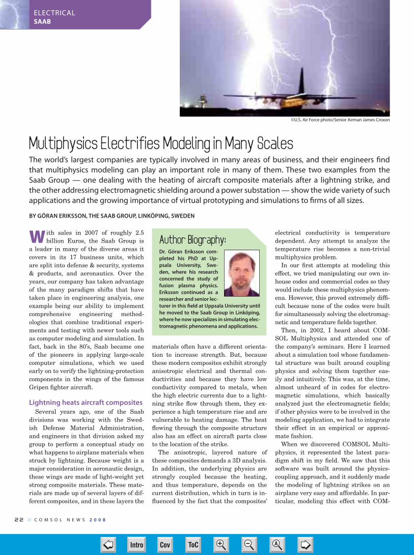
22 // C O M S O L N E W S 2 0 0 8
ELECTRICALSAAB
W ith sales in 2007 of roughly 2.5
billion Euros, the Saab Group is
a leader in many of the diverse areas it
covers in its 17 business units, which
are split into defense & security, systems
& products, and aeronautics. Over the
years, our company has taken advantage
of the many paradigm shifts that have
taken place in engineering analysis, one
example being our ability to implement
comprehensive engineering method-
ologies that combine traditional experi-
ments and testing with newer tools such
as computer modeling and simulation. In
fact, back in the 80’s, Saab became one
of the pioneers in applying large-scale
computer simulations, which we used
early on to verify the lightning-protection
components in the wings of the famous
Gripen fighter aircraft.
Lightning heats aircraft composites
Several years ago, one of the Saab
divisions was working with the Swed-
ish Defense Material Administration,
and engineers in that division asked my
group to perform a conceptual study on
what happens to airplane materials when
struck by lightning. Because weight is a
major consideration in aeronautic design,
these wings are made of light-weight yet
strong composite materials. These mate-
rials are made up of several layers of dif-
ferent composites, and in these layers the
materials often have a different orienta-
tion to increase strength. But, because
these modern composites exhibit strongly
anisotropic electrical and thermal con-
ductivities and because they have low
conductivity compared to metals, when
the high electric currents due to a light-
ning strike flow through them, they ex-
perience a high temperature rise and are
vulnerable to heating damage. The heat
flowing through the composite structure
also has an effect on aircraft parts close
to the location of the strike.
The anisotropic, layered nature of
these composites demands a 3D analysis.
In addition, the underlying physics are
strongly coupled because the heating,
and thus temperature, depends on the
current distribution, which in turn is in-
fluenced by the fact that the composites’
electrical conductivity is temperature
dependent. Any attempt to analyze the
temperature rise becomes a non-trivial
multiphysics problem.
In our first attempts at modeling this
effect, we tried manipulating our own in-
house codes and commercial codes so they
would include these multiphysics phenom-
ena. However, this proved extremely diffi-
cult because none of the codes were built
for simultaneously solving the electromag-
netic and temperature fields together.
Then, in 2002, I heard about COM-
SOL Multiphysics and attended one of
the company’s seminars. Here I learned
about a simulation tool whose fundamen-
tal structure was built around coupling
physics and solving them together eas-
ily and intuitively. This was, at the time,
almost unheard of in codes for electro-
magnetic simulations, which basically
analyzed just the electromagnetic fields;
if other physics were to be involved in the
modeling application, we had to integrate
their effect in an empirical or approxi-
mate fashion.
When we discovered COMSOL Multi-
physics, it represented the latest para-
digm shift in my field. We saw that this
software was built around the physics-
coupling approach, and it suddenly made
the modeling of lightning strikes on an
airplane very easy and affordable. In par-
ticular, modeling this effect with COM-
Multiphysics Electrifies Modeling in Many ScalesThe world’s largest companies are typically involved in many areas of business, and their engineers find
that multiphysics modeling can play an important role in many of them. These two examples from the
Saab Group — one dealing with the heating of aircraft composite materials after a lightning strike, and
the other addressing electromagnetic shielding around a power substation — show the wide variety of such
applications and the growing importance of virtual prototyping and simulations to firms of all sizes.
BY GÖRAN ERIKSSON, THE SAAB GROUP, LINKÖPING, SWEDEN
Author Biography:Dr. Göran Eriksson com-
pleted his PhD at Up-
psala University, Swe-
den, where his research
concerned the study of
fusion plasma physics.
Eriksson continued as a
researcher and senior lec-
turer in this field at Uppsala University until
he moved to the Saab Group in Linköping,
where he now specializes in simulating elec-
tromagnetic phenomena and applications.
©U.S. Air Force photo/Senior Airman James Croxon
22-23-24-CN Saab 2008.indd 22 3/25/08 1:31:29 PMCov ToC + – ➭
➮
AIntro

C O M S O L N E W S 2 0 0 8 // 23
ELECTRICALSAAB
SOL Multiphysics is possible thanks to
the software’s ability to solve virtually
any set of coupled differential equations.
In addition, we can easily add other
physical effects such as wind cooling and
black-body radiation heating that arises
from the hot lightning channel, which is
the 1-cm thick channel of ionized hot air
(10,000-20,000°C) where the lightning
discharge flows onto an airplane wing.
Figure 1 shows the results of one such
simulation of the heating caused by a
current pulse from lightning injected into
the leading edge of a wing that consists
of two layers of different anisotropic and
homogeneous composite materials1. The
current is injected across a small circular
area in the front.
The figure shows the distribution of cur-
rent density on a number of vertical and
horizontal slices through the structure at
an instant in time just after the lightning
has struck. In the left image, the slice
plot shows current density while stream-
lines indicate the current’s path. In the
figure on the right, the slice plot describes
the temperature, and the boundary plot
in the middle of the geometry shows the
electric potential.
The figure on the right shows where
the temperature distribution reaches the
material’s melting temperature, 300°C. It
is evident that the outer material layer,
which has the lowest electrical conduc-
tivity, is severely damaged by the tem-
perature rise while the inner layer is not.
Furthermore, it is easy to study how the
extent of the damage is influenced by the
degree of material anisotropies.
We validated this methodology for
simulating lightning strikes against
actual test results and found excellent
agreement. We also learned that radia-
tive heating from the lightning channel
also plays an important role. The find-
ings from these simulations had a major
impact on construction techniques and
provided useful design rules for the next
generation of advanced materials for
aircraft structures.
Meanwhile, we have used electromag-
netic simulations to analyze a variety of
other aircraft-related applications such as
antenna diagrams, antenna-to-antenna
couplings, radar cross-sections, interfer-
ence propagation, printed circuit board
designs, and test setup optimization.
As I started learning the other ad-
vantages of COMSOL Multiphysics, I
began using it more and more in other
simulation projects. I have found it very
easy to use with a short learning curve.
Any user can get right into the details
of modeling immediately, particularly
with the help of its Model Libraries. I
also found the company’s support team
to be the best I have ever come across.
Tricks for handling
conductive layers
Another project where COMSOL Mul-
tiphysics played a key role concerned
one of our external customers, ABB. In
this case we were modeling the elec-
tromagnetic effects on the casing (the
electromagnetic shielding) surrounding
a voltage substation. These electricity-
distribution systems are used to trans-
form voltages between different forms
and levels and thus provide the link be-
tween high-voltage transmission lines
and the domestic electricity supply.
Substations contain many components
such as switches, transformers, and
reactor coils that generate electromag-
netic fields. The strong fields emanating
from the transformers must frequently
be shielded so as to protect other equip-
Figure 2: COMSOL Multiphysics allows users to implement an expression for a conducting layer so the
software treats a 3D structure as a 2D surface but nonetheless simulates the 3D behavior. Such can be
useful for simulating thin internal borders, such as possible shielding layers modifying the near-field
from a cellular phone.
Figure 1: Model of lightning striking an airplane wing. On the left: the slice plot shows current density
and the streamlines show current path. On the right: the slice plot shows the temperature, and the
boundary plot shows the electric potential from the lightning strike.
22-23-24-CN Saab 2008.indd 23 3/25/08 1:31:48 PMCov ToC + – ➭
➮
AIntro
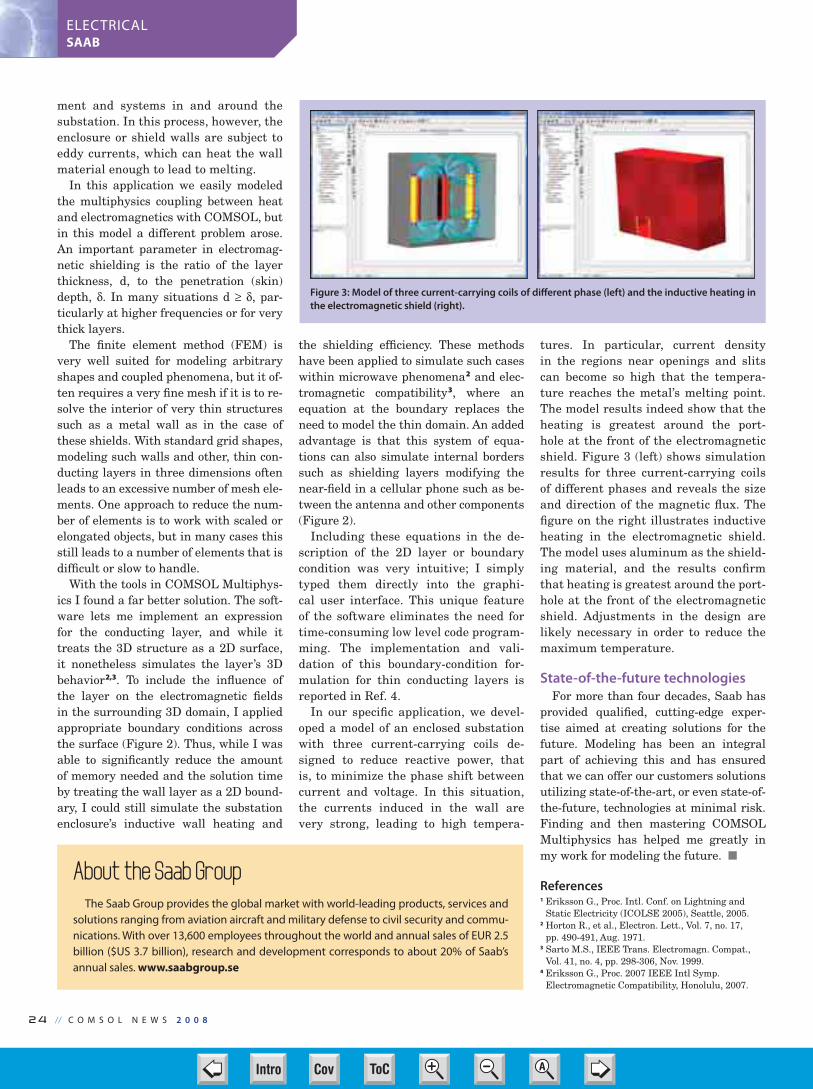
24 // C O M S O L N E W S 2 0 0 8
ELECTRICALSAAB
ment and systems in and around the
substation. In this process, however, the
enclosure or shield walls are subject to
eddy currents, which can heat the wall
material enough to lead to melting.
In this application we easily modeled
the multiphysics coupling between heat
and electromagnetics with COMSOL, but
in this model a different problem arose.
An important parameter in electromag-
netic shielding is the ratio of the layer
thickness, d, to the penetration (skin)
depth, . In many situations d , par-
ticularly at higher frequencies or for very
thick layers.
The finite element method (FEM) is
very well suited for modeling arbitrary
shapes and coupled phenomena, but it of-
ten requires a very fine mesh if it is to re-
solve the interior of very thin structures
such as a metal wall as in the case of
these shields. With standard grid shapes,
modeling such walls and other, thin con-
ducting layers in three dimensions often
leads to an excessive number of mesh ele-
ments. One approach to reduce the num-
ber of elements is to work with scaled or
elongated objects, but in many cases this
still leads to a number of elements that is
difficult or slow to handle.
With the tools in COMSOL Multiphys-
ics I found a far better solution. The soft-
ware lets me implement an expression
for the conducting layer, and while it
treats the 3D structure as a 2D surface,
it nonetheless simulates the layer’s 3D
behavior2,3. To include the influence of
the layer on the electromagnetic fields
in the surrounding 3D domain, I applied
appropriate boundary conditions across
the surface (Figure 2). Thus, while I was
able to significantly reduce the amount
of memory needed and the solution time
by treating the wall layer as a 2D bound-
ary, I could still simulate the substation
enclosure’s inductive wall heating and
the shielding efficiency. These methods
have been applied to simulate such cases
within microwave phenomena2 and elec-
tromagnetic compatibility3, where an
equation at the boundary replaces the
need to model the thin domain. An added
advantage is that this system of equa-
tions can also simulate internal borders
such as shielding layers modifying the
near-field in a cellular phone such as be-
tween the antenna and other components
(Figure 2).
Including these equations in the de-
scription of the 2D layer or boundary
condition was very intuitive; I simply
typed them directly into the graphi-
cal user interface. This unique feature
of the software eliminates the need for
time-consuming low level code program-
ming. The implementation and vali-
dation of this boundary-condition for-
mulation for thin conducting layers is
reported in Ref. 4.
In our specific application, we devel-
oped a model of an enclosed substation
with three current-carrying coils de-
signed to reduce reactive power, that
is, to minimize the phase shift between
current and voltage. In this situation,
the currents induced in the wall are
very strong, leading to high tempera-
tures. In particular, current density
in the regions near openings and slits
can become so high that the tempera-
ture reaches the metal’s melting point.
The model results indeed show that the
heating is greatest around the port-
hole at the front of the electromagnetic
shield. Figure 3 (left) shows simulation
results for three current-carrying coils
of different phases and reveals the size
and direction of the magnetic flux. The
figure on the right illustrates inductive
heating in the electromagnetic shield.
The model uses aluminum as the shield-
ing material, and the results confirm
that heating is greatest around the port-
hole at the front of the electromagnetic
shield. Adjustments in the design are
likely necessary in order to reduce the
maximum temperature.
State-of-the-future technologiesFor more than four decades, Saab has
provided qualified, cutting-edge exper-
tise aimed at creating solutions for the
future. Modeling has been an integral
part of achieving this and has ensured
that we can offer our customers solutions
utilizing state-of-the-art, or even state-of-
the-future, technologies at minimal risk.
Finding and then mastering COMSOL
Multiphysics has helped me greatly in
my work for modeling the future.
References1 Eriksson G., Proc. Intl. Conf. on Lightning and
Static Electricity (ICOLSE 2005), Seattle, 2005.2 Horton R., et al., Electron. Lett., Vol. 7, no. 17,
pp. 490-491, Aug. 1971.3 Sarto M.S., IEEE Trans. Electromagn. Compat.,
Vol. 41, no. 4, pp. 298-306, Nov. 1999.4 Eriksson G., Proc. 2007 IEEE Intl Symp.
Electromagnetic Compatibility, Honolulu, 2007.
Figure 3: Model of three current-carrying coils of different phase (left) and the inductive heating in the electromagnetic shield (right).
About the Saab GroupThe Saab Group provides the global market with world-leading products, services and
solutions ranging from aviation aircraft and military defense to civil security and commu-
nications. With over 13,600 employees throughout the world and annual sales of EUR 2.5
billion ($US 3.7 billion), research and development corresponds to about 20% of Saab’s
annual sales. www.saabgroup.se
22-23-24-CN Saab 2008.indd 24 3/25/08 1:32:44 PMCov ToC + – ➭
➮
AIntro

The Support Team is here to help you get the
most out of your COMSOL products. We strive to
provide speedy service, and we try to make it easy
for you to find the information you need fast.
The Support Team also maintains a database of
almost 1,000 demonstration models that can help
you learn how to fully simulate your application.
And, if your application is so unique that a ready
model is not available, we can guide you through
the model set up.
C O M S O L N E W S 2 0 0 8 // 25
Q&AQuestions & Answers from the Support Desk
Here are a few snippets from entries in the COMSOL
Knowledge Base. Visit www.comsol.com/support/ for
answers to your questions or contact the Support Desk at
Q1: I am modeling in the frequency domain. How can I de-
fine materials with losses?
A1: No matter what physics you are modeling, you can al-
ways represent losses as a complex material property
with a negative imaginary part. For instance, in optics,
setting the refractive index to 2.1-0.5*i will give
you a lossy material. Often, you will have other options
as well, such as setting a flow resistivity in acoustics, a
non-zero conductivity in electromagnetics, or a loss
factor in structural mechanics. If, on the other hand,
you want to model a material with gain, you can do
that with a positive imaginary part. To learn more about
how to do this, see Knowledge Base Solution 1009.
Q2: I’d like to track the interface between two immiscible
fluids. I have heard of several techniques such as Vol-
ume of Fluids, Level Sets, and ALE. What is the differ-
ence between them and which one should I use?
A2: While the Volume of Fluid method uses a discrete
function to trace the interface, the Level Set method
represents the interface as the
contour of a smooth function.
Typically, the Level Set method
gives the surface tension and
position of the interface with far
better accuracy, but it does notguarantee mass conservation.
COMSOL Multiphysics, howev-
er, uses an enhanced version of
the Level Set method that also
adjusts your models to provide
good mass conservation.
The ALE method continuously deforms the computa-
tional mesh to adapt it to the current shape of each fluid
domain. ALE can be advantageous in cases without topo-
logical changes, and it is also useful for fluid-structure inter-
actions. See Knowledge Base Solution 1025 to read more
about the differences between each of these methods.
Q3: When I increase the frequency in my induction heat-
ing model, the skin effect forces my currents toward
the surface. I can’t afford a mesh that is fine enough to
resolve them.
A3: Use the impedance boundary condition. This means
you exclude the interior of your metals from your model
and treat all induced currents as surface currents. This is
a good approximation whenever your metal domains
are much thicker than the skin depth. Find out more in
Knowledge Base Solution 1004, which provides a con-
cise description of impedance boundary conditions.
The more processors you use
for computing, the quicker
your simulations run. By al-
lowing for multicore processing
of your COMSOL Multiphysics
models, you can achieve a sig-
nificant speedup in 3D meshing,
assembly, and solving. Here are
some tips to help you better le-
verage your multicore platform
for multiphysics modeling.
To run COMSOL Multiphysics
with multicore processor sup-
port on Linux or Sun platforms,
use the command:
comsol -np n
where n is the number of proces-
sor cores you want to use.
In Windows, COMSOL Mul-
tiphysics will use all available
cores by default. You can use
the same command if you want
to reserve some cores for a sepa-
rate COMSOL session or for
other tasks.
In a multicore environment,
COMSOL distributes meshing
between cores subdomain by
subdomain. To maximize per-
formance, use more subdomains
than the physics of your model
would otherwise dictate. Say, for
instance, that you have a quad-
core processor, and you would
like to speed up the meshing
process in a model with a com-
plex geometry but nominally
only one subdomain. Try split-
ting the geometry into four sub-
domains, each with similar size
and complexity, and then do
your meshing.
In the solution process, the de-
gree of parallelization mostly de-
pends on which solver you use.
Generally, the solver that ben-
efits most from multicore pro-
cessing is the PARDISO direct
solver. All iterative solvers and
smoothers except Incomplete LU
are also parallelized.
Speed Up Your Simulations with Parallel Processing
Models with many degrees of
freedom, such as this static mi-
cromixer, benefit greatly from
multicore parallel processing.
Linus Andersson,
COMSOL Support
Model of droplet breakup
created with the Level Set
method.
25-CN Support 2008.indd 25 3/25/08 1:33:15 PMCov ToC + – ➭
➮
AIntro

26 // C O M S O L N E W S 2 0 0 8
SEMICONDUCTORSSTMICROELECTRONICS
We want our electronic gadgets to
function properly for long periods
of time, and service lifetimes are particu-
larly critical where systems must work
reliably far longer. It is thus important to
know how long integrated circuits (ICs)
will function properly. It’s not practical
to test ICs in the reality conditions and
thus wait years to find out when failures
start to occur naturally or through opera-
tion. Semiconductor engineers have con-
sequently developed accelerated life-cycle
tests, which place components under high
current stress and temperature. This
helps predict their useful lifetimes by ex-
trapolation. Based on such experiments
we have also started to develop models
that predict semiconductor lifetimes.
These models don’t predict when a spe-
cific device will fail, but can predict, with
reasonable certainty, the rate of failure
under specific conditions. And semicon-
ductor companies are expending a great
deal of effort to make these models as ac-
curate as possible. In order to do so, pro-
cess engineers need a better understand-
ing of the underlying failure mechanisms.
With the help of COMSOL Multiphysics,
myself and others at the $10 billion com-
pany STMicroelectronics are studying
the mechanisms that bring about one of
the primary causes for IC failure, electro-
migration in interconnects.
A complex multiphysics problem
With the scaling down of semiconduc-
tor devices, current density in the metal
interconnects joining individual transis-
tors increases. Up to now, lifetime models
have been based on empirical methods.
Thus, an evaluation of potential failure
modes is very important as STMicroelec-
tronics brings new advanced CMOS tech-
nologies onto the market.
In devices fabricated with these process
technologies, interconnect copper lines
can be just 100nm thick and roughly the
same height. The prevalent failure mode
for interconnects is electromigration,
which is the net transport of material
caused by conducting electrons colliding
with metal ions. Over time, a number of
metal atoms are knocked from their orig-
inal positions due to this phenomenon
commonly known as an “electron wind.”
The subsequent vacancies or holes in the
crystal structure are due to the migra-
tion of metal atoms, and over time, these
can accumulate to form minute voids
that lead to open circuits and device
failure, see Figure 1. Vacancy flux de-
pends on several driving forces including
the gradients of the hydrostatic stress,
temperature and
electric potential.
Several character-
istics of the metal
interconnect have
a strong influence
on their lifespan.
These include the
conductor’s dimen-
sions, the material
properties, the elec-
trochemical depo-
sition process, and
the chemical me-
chanical planariza-
tion (CMP) process
used to fabricate the
interconnects.
When our reliabil-
ity engineers per-
form accelerated life tests, they want to
work with worst-case conditions. With
the deeper understanding of electromi-
gration we gain with our multiphysics
model, we can be much more certain
that we have actually stipulated the
worst-case conditions.
Realistic simulation of
the microstructure
We chose COMSOL Multiphysics be-
cause it was able to efficiently handle all
Improving Prediction of Semiconductor LifetimesBY F. CACHO AND V. FIORI, STMICROELECTRONICS , CROLLES, FRANCE
Figure 1: A scanning electron microscopy image of a copper line interconnect where a void has devel-
oped due to vacancy accumulation. This has led to a broken circuit.
Figure 2: The extent of relative vacancy concentration
through a copper interconnect line connected to the via
and embedded in oxide. The higher relative vacancy occurs
in the vicinity of the via, which is to be expected. Yet, areas
of relative vacancy concentration are also prevalent at the
boundaries between grains.
26-27-CN STMicroelectronics 200826 26 3/25/08 1:33:52 PMCov ToC + – ➭
➮
AIntro

C O M S O L N E W S 2 0 0 8 // 27
SEMICONDUCTORSSTMICROELECTRONICS
the physical factors that influence elec-
tron migration in metallic interconnects.
Our model couples the transport of vacan-
cies with structural mechanics and ther-
mal diffusion. We started with a 2D model
that enabled us to benchmark the solu-
tion and gain confidence in the approach.
However, realistic diffusion paths involve
multiple metal/metal interfaces, which
drove us to create a 3D model, where we
studied the transient vacancy transport
with realistic microstructure and kinetic
paths, see Figure 2.
The model couples several physics:
standard diffusion due to concentration
gradients; the “electron wind” driven by
a chemical potential difference; hydro-
static stress and heat-induced atomic dif-
fusion. COMSOL Multiphysics provides
a number of tools for modeling such phe-
nomena: the ease of creating a geometry
that accounts for crystal grains and in-
terfaces between different components,
such as interconnects and vias; the ease
of modeling different coefficients (for both
electromigration and structural mechan-
ics); and the ease of modeling multiphys-
ics phenomenon (coupling the diffusion
equations from the DC current to the
physics of structural mechanics and heat
transfer), see Figure 3.
After studying the model results, we
learned that, as a first approximation,
the location of the void nucleation can be
determined by the occurrence of a criti-
cal vacancy concentration. The model en-
ables us to predict that maximum concen-
tration as a function of applied current,
initial stress, temperature and, above all,
the line’s geometry. As a result, we now
have a preliminary predictive model for
the lifetime of
metal inter-
connects, see
Figure 4.
These mod-
eling results
are important
to our reli-
ability teams because our accelerated
tests must be very predictive and accu-
rate. However, there are many physical
effects engineers don’t yet fully under-
stand. We are currently using COMSOL
Multiphysics to develop better predictive
failure models so that we can save time
in our qualification process and also be
sure that we are indeed using worst-case
scenarios. With the help of these models
we also get insight into process design
rules that define, for instance, the mini-
mum size for interconnects.
The modeling team
Hired by STMicroelectronics spe-
cifically to do mechanical and thermal
simulation, the two authors are part of
the modeling team at the company’s site
in Crolles, France. They spend roughly
60% of their time simulating semicon-
ductor aspects such as thermal effects
and Joule heating, as well as nonlinear
mechanical effects.
READ THE RESEARCH PAPER AT:comsol.com/industry/papers/2892/
Figure 4: The evolution of relative vacancy concentration along a line through
the center of the model. The peaks occur close to the via and in the vicinity of the
grain boundaries.
About the AuthorsFlorian Cacho received his Ph.D. in
Material Science from l’Ecole des Mines
de Paris. Since 2005, he has been a
mechanical & thermal engineer in the
Technology Modeling Department at
STMicroelectronics in Crolles, France.
Vincent Fiori has a masters degree
in Mechanical Engineering from the
National Institute of Applied Science,
Lyon. He joined STMicroelectronics in
2000 and currently leads projects on
mechanical and thermal modeling ac-
tivities. These are particularly focused
on the front-end technology develop-
ment of semiconductor production.
The modeling team at STMicroelectronics standing
outside their facility in Crolles, France. From left: Sé-
bastien Gallois, Romuald Roucou, Vincent Fiori and
Florian Cacho.
Figure 3: von Mises stresses in a slice through the
copper interconnect line. Areas of greatest stress
occur close to the via at the first grain boundary.
26-27-CN STMicroelectronics 200827 27 3/25/08 1:34:36 PMCov ToC + – ➭
➮
AIntro

28 // C O M S O L N E W S 2 0 0 8
EDUCATIONRENSSELAER POLYTECHNIC INSTITUTE
A s a professor in the Department of
Chemical and Biological Engineer-
ing at Rensselaer Polytechnic Institute
in Troy, NY, and author of the textbook,
Transport Phenomena Fundamentals,
Joel L. Plawsky has been using COM-
SOL Multiphysics for more than five
years. “As a research tool, COMSOL has
simplified our lives quite a bit. Instead
of having to write code and laboriously
work to visualize the solutions, we are
now able to be much more efficient and
productive. COMSOL enables us to
spend less time solving the problem
and more time understanding the
underlying physical phenomena and
analyzing the results,” he said.
Professor Plawsky’s research team
recently has been investigating gate
and interconnect dielectric reliability
as a function of operating tempera-
ture and the electric field applied to
the structure. They are interested in
how metal ions injected into the di-
electric affect the time required for
the devices to fail. COMSOL was
used to simulate a dielectric break-
down in a transistor that led his
team to uncover some new physics
about how that process works. Pro-
fessor Plawsky added, “Using COM-
SOL, we’ve done things at Rensselaer
such as simulating a whole piece of
pilot scale equipment that we built to
make coated aerogel superinsulation
for NASA. We’ve also simulated tem-
perature profiles in the active region of
LEDs, the performance of wickless mi-
cro heat pipes, and the flow around an
Aerobee flying ring.”
According to Professor Plawsky, model-
ing and simulation software is an essential
part of the modern-day engineer’s toolkit,
which is why integrating software into the
curriculum at Rensselaer is a priority. He
first began using COMSOL as a teaching
tool for transport phenomena: “There are
many finite element packages out there
and many packages that do one or the
other of the transport processes chemical
engineers need; however, it turns out that
for transport processes and especially for
coupled transport processes, COMSOL is
the best program available.”
Currently, COMSOL is used in the un-
dergraduate and graduate transport pro-
cesses sequence as well as in the gradu-
ate math methods course at Rensselaer.
“COMSOL is something that chemical
engineers can jump right into and read-
ily use. The equations and the jargon
that the program uses are nearly identi-
cal to how we teach the discipline in our
courses. So the software becomes a natu-
ral extension of what we do in the class-
room and something students will want
to use,” said Plawsky.
As for the text used in the classroom,
a second edition of Professor Plawsky’s
book (published by Taylor & Francis) is
due out for the 2009/2010 academic year
and will make extensive use of COM-
SOL as a teaching tool. “COMSOL gets
integrated with the book from the very
beginning as both examples and home-
work problems. Some of the introduc-
tory concepts in the book are some
of the easiest things to simulate in
COMSOL, so students who are unfa-
miliar with the program can start out
working some modules early on,” he
said. “Using the textbook, students
can get a feel for how the program
works, and then as we build up in
complexity in the textbook, we begin
to build up in complexity with COM-
SOL by introducing new features and
new phenomena.”
DOWNLOAD MODELS FROM THE
TEXTBOOK ”TRANSPORT PHENOMENA
FUNDAMENTALS” AT:
www.comsol.com/academic/resources/
In the Classroom: Rensselaer Polytechnic Institute Puts COMSOL to the TestBY CATHLEEN LAMBERTSON
This figure shows the pressure distribution and
flow streamlines about an aerobee flying ring at
the point where the forward stagnation point is
very near the lower tip of the aerobee. The tre-
mendous lift generated contributes to the long
distance flying ability of the ring.
This figure shows a contour plot of the electric field gen-
erated by copper ion diffusion in a porous low dielectric
constant material. Failure occurs when the electric field
crosses a threshold value shown by the maximum point
on the figure. This point occurs very near the classical
boundary separation point in flow over a cylinder.
Joel L. Plawsky is a professor in the Depart-
ment of Chemical and Biological Engineering at
Rensselaer Polytechnic Institute in Troy, NY, and
author of the textbook, Transport Phenomena Fundamentals.
28-CN RPI NY 2008.indd 28 3/26/08 1:31:53 PMCov ToC + – ➭
➮
AIntro

C O M S O L N E W S 2 0 0 8 // 29
EDUCATIONRENSSELAER POLYTECHNIC INSTITUTE
Keeping your engineering skills up
to date and career on track requires
constant learning. When it comes to con-
tinuing education for professional en-
gineers, perhaps no institution offers a
greater degree of engineering expertise
and flexibility than Rensselaer at Hart-
ford, Connecticut, a branch campus of
the technology-based education and aca-
demic research leader Rensselaer Poly-
technic Institute.
Associate Professor Gutierrez-Mira-
vete of the Department of Engineering
Science uses COMSOL Multiphysics to
help him teach multiphysics phenom-
ena and the practical applications of
partial differential equations (PDEs) to
engineers from such high-tech heavy-
weights as Pratt & Whitney and United
Technologies. We asked Professor Guti-
errez-Miravete about the role COMSOL
Multiphysics plays expanding the skills
of practicing engineers.
COMSOL News: Professor Ernesto
Gutierrez-Miravete, what courses do you
teach?
Gutierrez-Miravete: I teach a broad
variety of courses, including Advanced
Engineering Mathematics, Mechanics of
Solid Materials, Mathematical Modeling
of Manufacturing Processes, and Sto-
chastic Simulation.
COMSOL News: Tell us a little about
your students.
Gutierrez-Miravete: Practically all
our students are successful, practic-
ing engineers. On average, they have
5-7 years of experience in the field, and
many are in their late 20s or early 30s.
Most are degree-seeking. In my depart-
ment, most of the students are mechani-
cal engineers, but we also get aero-as-
tro, industrial and materials engineers,
as well as some physicists. A significant
number of older students also attend
Rensselaer, most seeking a follow-up
management degree but also some after
a second engineering degree.
COMSOL News: How does COMSOL
Multiphysics fit into your classroom?
Gutierrez-Miravete: COMSOL is a
natural fit, as it constitutes an excellent
teaching aid that uses the language ana-
lytical engineers are comfortable with. I
very much appreciate the short learning
curve and the ability to let students fo-
cus on the examination of results rather
than on programming details.
COMSOL News: How does COMSOL
Multiphysics help you teach about
the relationship of multiple physics
phenomena?
Gutierrez-Miravete: Many engineer-
ing problems are truly multiphysics. For
instance, one examines flow in turbine
airfoils, among other reasons, because of
their effect on the temperature and stress
in the foil; tool wear in titanium machin-
ing is due to cobalt diffusion which in
turn depends on the temperature of the
tool; a magnetic field produces forces in a
liquid metal that drive fluid flow.
COMSOL News: How do your students
react to COMSOL Multiphysics? Does it
help them understand the practical ap-
plication of PDEs to their work life?
Gutierrez-Miravete: Most students
find COMSOL easy to learn; they also
like to be able to formulate their mod-
els using the language of differential
equations. Several of my students are
now using COMSOL to create models of
real-world systems they work with on a
daily basis.
Engineers Advance SkillsAssociate Professor Ernesto Gutierrez-Miravete of the Department of Engineering Science at Rensselaer at
Hartford explains why COMSOL is a natural fit in the continuing engineering education classroom.
Ernesto Gutierrez-Miravete (far right) finds that his many of continuing engineering education students at Rensselaer at Hartford use COMSOL Multiphysics to create models of real-world sys-tems they work with daily. From left to right in the front row are Eric Rogers, Douglas Blake, and Gutierrez-Miravete.
Rensselaer at HartfordRensselaer at Hartford offers an educational experience for students who need to bal-
ance their professional, academic, and personal lives. It offers graduate and specialized
programs, several graduate certificates, professional development programs, and a vari-
ety of additional educational opportunities. For more information, visit Rensselaer at Hart-
ford on the web at www.ewp.rpi.edu/hartford. Links to examples of his students’ work
www.comsol.com/academic/resources/courses/.
“COMSOL constitutes an
excellent teaching aid
that uses the language
analytical engineers are
comfortable with.”
— Ernesto Gutierrez-Miravete,
Rensselaer at Hartford
29-CN Guiterrez 2008.indd 29 3/25/08 1:36:11 PMCov ToC + – ➭
➮
AIntro

30 // C O M S O L N E W S 2 0 0 8
AUTOMOTIVECONTINENTAL
A s a major worldwide supplier,
Continental manufactures a wide
range of products for all types of cars,
trucks or motorcycles. At our factory,
these products include sensors, switch-
es, and printed-circuit assemblies for
measuring temperatures, pressures, flu-
id levels and flows, and vehicle speeds,
while also controlling many of the ac-
cessories in these vehicles. Our cus-
tomers are in a continual, unrelenting
process of upgrading their existing ve-
hicle designs or introducing new models
— and the requirements for components
change just as frequently. It is only with
the help of computer modeling and sim-
ulations that we can keep up with the
demand for all these new designs on a
timely basis.
Continental’s factory in Frenstat,
Czech Republic, has roughly 2,200 em-
ployees, with 60 working in the R&D de-
partment, of which three of us develop
simulations. Before I joined the compa-
ny, when it was known as Siemens VDO,
the R&D department was just starting
to use simulation software. Prior to that,
the simulations for new products were
provided by external consultants.
I came to Continental with a bit of ex-
perience from modeling and designing
with finite-element analysis and CAD
software. The company hired me with
the charter of bringing full-scale model-
ing to the product-development process
where we could analyze far more than
just structural integrity. COMSOL Mul-
tiphysics had newly arrived at the de-
partment, and I started by applying it to
model heat-transfer, structural applica-
tions and also fluid flow.
Learning more about
a well-studied sensor
One of the first fluid-flow investiga-
tions I took on was the analysis of a
mass airflow sensor, which is fitted to an
air-intake system where air must pass
through a filter and into the automobile
engine. A typical sensor measures flows
as high as 50 m/s. The engine computer
uses data from this and other sensors to
adjust the amount of fuel injected into
the engine. In this case, I used COM-
SOL to evaluate the software’s compu-
tational abilities by comparing results
from the software (Figure 1) with pre-
vious experimental calculations from
colleagues who develop such sensors.
I was pleased to find close agreement
between experimental data and simula-
tion results, which gave me confidence
in COMSOL Multiphysics.
In Figure 1, the inverted “U” tube in-
corporates a hot-film anemometer whose
output is directly related to air flow. The
model solves the turbulent flow using
COMSOL Multiphysics’ k- application
mode and describes the flow that enters
the chamber. The color plot indicates
magnitude of the velocity while the
streamlines show the velocity field.
The simulation of components such as
this has become an integral part of our
overall development cycle. We now use
COMSOL to investigate existing designs
in order to improve them, better utilize
them or better implement them, and
we then pass this advice on to our R&D
Department. Those engineers, working
in Pro/ENGINEER®, then come back to
us with improved designs or sometimes
even completely new designs based on
our results and specifications from our
customers. Sometimes they supply us
with a variety of alternate designs for
a given product that we then simulate,
allowing them to select the most ap-
propriate one for which to then build
a prototype. Our Testing Department
takes this prototype and evaluates the
component’s behavior in real-life condi-
tions, taking measurements on a num-
ber of relevant parameters such as the
mechanical and thermal loads applied
in the vehicle.
This inter-team collaboration leads to
better model parameters for more accu-
rate simulations as well as better test-
ing procedures. It is vital that we verify
our models with their experimental re-
sults and that we calibrate our models
with their data and procedures.
Shaving seconds from
response time
Figure 2 illustrates a further exam-
ple of how COMSOL has made a posi-
tive contribution to our joint efforts.
It shows a 3D model of a sensor that
measures the electrical resistance that
changes with temperature. In order to
give a fast temperature reading, though,
the sensor must accurately account for
the response time its transducer mate-
rial needs to reach to the surrounding
environment’s temperature. Of course,
the sensor must be accurate too.
The first step was to import the as-
sembly geometry from Pro/ENGINEER
using COMSOL’s CAD Import Module.
During that step, we removed some of
the small geometry features that were
Rapid Developments of Sensors in Vehicle DesignBY MARTIN SÁS, CONTINENTAL CORPORATION (FORMERLY SIEMENS VDO), FRENSTAT, CZECH REPUBLIC
Author Biography:Martin Sás has been a modeling engineer at
Continental (formerly Siemens VDO) since
2006. Prior to this he worked in quality,
mechanical design and development in the
automotive industry and was involved with
high-precision testing and standards. Sás
received his MSc. in Mechanical Engineer-
ing from the Slovak Technical University.
Parallel to his work with Continental, he is
completing his Ph.D in heat transfer and
high-precision temperature measurement
techniques.
Figure 1: Model of a mass airflow sen-
sor. The inverted “U” tube incorporates
a hot-film anemometer whose output is
directly related to air flow.
Pro/ENGINEER is a registered trademark of Parametric Technology Corporation
or its subsidiaries in the U.S. and in other countries.
30-31-32-33-CN Continental-NOX 230 30 3/25/08 1:36:56 PMCov ToC + – ➭
➮
AIntro

C O M S O L N E W S 2 0 0 8 // 3 1
AUTOMOTIVECONTINENTAL
unimportant for our analysis but that
would have led to an unnecessarily
large mesh. We next assigned material
properties and boundary conditions to
simulate the sensor’s surrounding en-
vironment and operating conditions.
By modeling the transient temperature
distribution in this component, and es-
pecially the part that measures electri-
cal resistance, we can then calculate the
response time.
It was very simple to set up and solve
this model, which revealed invaluable
knowledge about the sensor’s overall de-
sign and its operating parameters. Fig-
ure 2 shows a photograph and an X-ray
image of the resistance-based tempera-
ture sensor. The model plot shows the
temperature distribution in the sensor
70 s after the temperature has changed
from 25 to 90°C.
To gain confidence in our model, we
ran experiments and compared the re-
sults, which were virtually the same for
both experiments and the model. Figure
3 illustrates the response time for a step
change in the temperature in the model
(red line) and an experimental bench-
marking test (blue line) based on the
ISO 4113 standard.
Some benefits: priceless
As we learned through these and
many other examples, the benefits of in-
troducing COMSOL Multiphysics to the
development cycle have been many and
varied. While some can be quantified in
terms of cost savings, others are more
intangible but just as important. For in-
stance, such “priceless” benefits consist
of a far better understanding of our de-
signs and materials along with how the
operating parameters and
surrounding environment
affects them. Where we once
received information only
about components’ structur-
al properties, we now have
information about feedback
times, eigenfrequencies,
temperature distributions,
flow fields and the impact
of different materials. Soon
we will also investigate how
cyclic thermal loads and ag-
ing degrade materials and
sensor characteristics and will also re-
search the multiphysics phenomenon of
the transient interaction of temperature
with flow.
The Development Department also
uses our models to communicate with
our customers and suppliers, leading to
improvements in the specifications they
provide us with. When our customers
have a better understanding of the com-
ponents and how each one reacts in its
operating environment, then we receive
even better specifications from them.
Model result also increases their confi-
dence in our products and capabilities.
Another benefit from simulating our
product designs is a reduction in the
number of physical prototypes. Instead
of producing five to ten prototypes when
testing a component, we now only pro-
duce two, and sometimes even a single
prototype is sufficient. While an initial
prototype made through stereolithogra-
phy can cost as much as $140 for each
component, the time spent testing it in-
curs costs far in excess of this.
The ease with which we can set up
models using COMSOL Multiphysics,
along with the fact that the software can
simulate all the phenomena and phys-
ics we need, has opened up a whole new
world of possibilities in improving our
designs. Instead of modeling just one
step in the development process, model-
ing has become an integral part in all of
the steps of the development process.
READ THE RESEARCH PAPER AT:www.comsol.com/industry/papers/2775/
Figure 2: A photograph and X-ray picture of a tempera-
ture sensor and a model plot of temperature distribution
over the whole of the sensor and on the sensing element
inside the cap.
Figure 3: Comparison of modeled values (red line)
and experimental values (blue line) for the re-
sponse time of a temperature sensor.
About Continental CorporationThe Continental Corporation is one
of the top five automotive suppliers
worldwide, manufacturing gasoline
and diesel systems, hybrid electric
drives, breaking systems, power train
control units, and a large variety of
sensors and actuators. With its pur-
chase of Siemens VDO in December
2007, Continental now realizes aggre-
gate annual sales of roughly 25 billion
euros with a worldwide workforce of
close to 140,000.Continental Team. From left David Kafka, Petr Be-
ran, Martin Sás, Rostislav Slavik, and Jan Haag.
30-31-32-33-CN Continental-NOX 231 31 3/25/08 1:38:24 PMCov ToC + – ➭
➮
AIntro
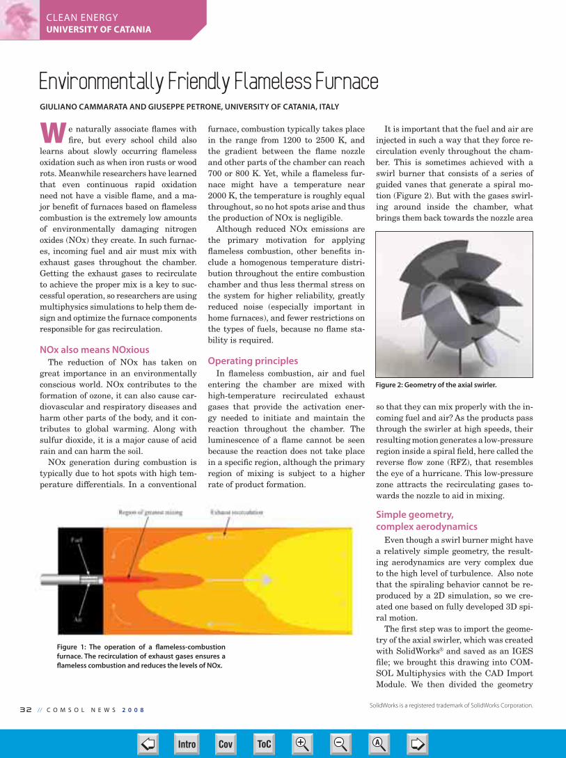
32 // C O M S O L N E W S 2 0 0 8
CLEAN ENERGYUNIVERSITY OF CATANIA
Environmentally Friendly Flameless Furnace GIULIANO CAMMARATA AND GIUSEPPE PETRONE, UNIVERSITY OF CATANIA, ITALY
W e naturally associate flames with
fire, but every school child also
learns about slowly occurring flameless
oxidation such as when iron rusts or wood
rots. Meanwhile researchers have learned
that even continuous rapid oxidation
need not have a visible flame, and a ma-
jor benefit of furnaces based on flameless
combustion is the extremely low amounts
of environmentally damaging nitrogen
oxides (NOx) they create. In such furnac-
es, incoming fuel and air must mix with
exhaust gases throughout the chamber.
Getting the exhaust gases to recirculate
to achieve the proper mix is a key to suc-
cessful operation, so researchers are using
multiphysics simulations to help them de-
sign and optimize the furnace components
responsible for gas recirculation.
NOx also means NOxious
The reduction of NOx has taken on
great importance in an environmentally
conscious world. NOx contributes to the
formation of ozone, it can also cause car-
diovascular and respiratory diseases and
harm other parts of the body, and it con-
tributes to global warming. Along with
sulfur dioxide, it is a major cause of acid
rain and can harm the soil.
NOx generation during combustion is
typically due to hot spots with high tem-
perature differentials. In a conventional
furnace, combustion typically takes place
in the range from 1200 to 2500 K, and
the gradient between the flame nozzle
and other parts of the chamber can reach
700 or 800 K. Yet, while a flameless fur-
nace might have a temperature near
2000 K, the temperature is roughly equal
throughout, so no hot spots arise and thus
the production of NOx is negligible.
Although reduced NOx emissions are
the primary motivation for applying
flameless combustion, other benefits in-
clude a homogenous temperature distri-
bution throughout the entire combustion
chamber and thus less thermal stress on
the system for higher reliability, greatly
reduced noise (especially important in
home furnaces), and fewer restrictions on
the types of fuels, because no flame sta-
bility is required.
Operating principles
In flameless combustion, air and fuel
entering the chamber are mixed with
high-temperature recirculated exhaust
gases that provide the activation ener-
gy needed to initiate and maintain the
reaction throughout the chamber. The
luminescence of a flame cannot be seen
because the reaction does not take place
in a specific region, although the primary
region of mixing is subject to a higher
rate of product formation.
It is important that the fuel and air are
injected in such a way that they force re-
circulation evenly throughout the cham-
ber. This is sometimes achieved with a
swirl burner that consists of a series of
guided vanes that generate a spiral mo-
tion (Figure 2). But with the gases swirl-
ing around inside the chamber, what
brings them back towards the nozzle area
so that they can mix properly with the in-
coming fuel and air? As the products pass
through the swirler at high speeds, their
resulting motion generates a low-pressure
region inside a spiral field, here called the
reverse flow zone (RFZ), that resembles
the eye of a hurricane. This low-pressure
zone attracts the recirculating gases to-
wards the nozzle to aid in mixing.
Simple geometry,
complex aerodynamics
Even though a swirl burner might have
a relatively simple geometry, the result-
ing aerodynamics are very complex due
to the high level of turbulence. Also note
that the spiraling behavior cannot be re-
produced by a 2D simulation, so we cre-
ated one based on fully developed 3D spi-
ral motion.
The first step was to import the geome-
try of the axial swirler, which was created
with SolidWorks® and saved as an IGES
file; we brought this drawing into COM-
SOL Multiphysics with the CAD Import
Module. We then divided the geometry
Figure 1: The operation of a flameless-combustion
furnace. The recirculation of exhaust gases ensures a
flameless combustion and reduces the levels of NOx.
Figure 2: Geometry of the axial swirler.
SolidWorks is a registered trademark of SolidWorks Corporation.
30-31-32-33-CN Continental-NOX 232 32 3/25/08 1:38:53 PMCov ToC + – ➭
➮
AIntro
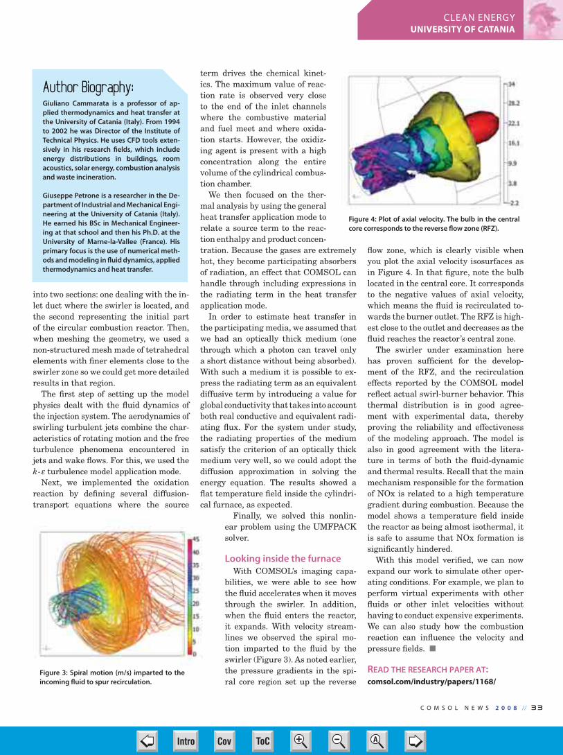
C O M S O L N E W S 2 0 0 8 // 33
CLEAN ENERGYUNIVERSITY OF CATANIA
into two sections: one dealing with the in-
let duct where the swirler is located, and
the second representing the initial part
of the circular combustion reactor. Then,
when meshing the geometry, we used a
non-structured mesh made of tetrahedral
elements with finer elements close to the
swirler zone so we could get more detailed
results in that region.
The first step of setting up the model
physics dealt with the fluid dynamics of
the injection system. The aerodynamics of
swirling turbulent jets combine the char-
acteristics of rotating motion and the free
turbulence phenomena encountered in
jets and wake flows. For this, we used the
k- turbulence model application mode.
Next, we implemented the oxidation
reaction by defining several diffusion-
transport equations where the source
term drives the chemical kinet-
ics. The maximum value of reac-
tion rate is observed very close
to the end of the inlet channels
where the combustive material
and fuel meet and where oxida-
tion starts. However, the oxidiz-
ing agent is present with a high
concentration along the entire
volume of the cylindrical combus-
tion chamber.
We then focused on the ther-
mal analysis by using the general
heat transfer application mode to
relate a source term to the reac-
tion enthalpy and product concen-
tration. Because the gases are extremely
hot, they become participating absorbers
of radiation, an effect that COMSOL can
handle through including expressions in
the radiating term in the heat transfer
application mode.
In order to estimate heat transfer in
the participating media, we assumed that
we had an optically thick medium (one
through which a photon can travel only
a short distance without being absorbed).
With such a medium it is possible to ex-
press the radiating term as an equivalent
diffusive term by introducing a value for
global conductivity that takes into account
both real conductive and equivalent radi-
ating flux. For the system under study,
the radiating properties of the medium
satisfy the criterion of an optically thick
medium very well, so we could adopt the
diffusion approximation in solving the
energy equation. The results showed a
flat temperature field inside the cylindri-
cal furnace, as expected.
Finally, we solved this nonlin-
ear problem using the UMFPACK
solver.
Looking inside the furnace
With COMSOL’s imaging capa-
bilities, we were able to see how
the fluid accelerates when it moves
through the swirler. In addition,
when the fluid enters the reactor,
it expands. With velocity stream-
lines we observed the spiral mo-
tion imparted to the fluid by the
swirler (Figure 3). As noted earlier,
the pressure gradients in the spi-
ral core region set up the reverse
flow zone, which is clearly visible when
you plot the axial velocity isosurfaces as
in Figure 4. In that figure, note the bulb
located in the central core. It corresponds
to the negative values of axial velocity,
which means the fluid is recirculated to-
wards the burner outlet. The RFZ is high-
est close to the outlet and decreases as the
fluid reaches the reactor’s central zone.
The swirler under examination here
has proven sufficient for the develop-
ment of the RFZ, and the recirculation
effects reported by the COMSOL model
reflect actual swirl-burner behavior. This
thermal distribution is in good agree-
ment with experimental data, thereby
proving the reliability and effectiveness
of the modeling approach. The model is
also in good agreement with the litera-
ture in terms of both the fluid-dynamic
and thermal results. Recall that the main
mechanism responsible for the formation
of NOx is related to a high temperature
gradient during combustion. Because the
model shows a temperature field inside
the reactor as being almost isothermal, it
is safe to assume that NOx formation is
significantly hindered.
With this model verified, we can now
expand our work to simulate other oper-
ating conditions. For example, we plan to
perform virtual experiments with other
fluids or other inlet velocities without
having to conduct expensive experiments.
We can also study how the combustion
reaction can influence the velocity and
pressure fields.
READ THE RESEARCH PAPER AT:comsol.com/industry/papers/1168/
Figure 3: Spiral motion (m/s) imparted to the
incoming fluid to spur recirculation.
Figure 4: Plot of axial velocity. The bulb in the central
core corresponds to the reverse flow zone (RFZ).
Author Biography:Giuliano Cammarata is a professor of ap-
plied thermodynamics and heat transfer at
the University of Catania (Italy). From 1994
to 2002 he was Director of the Institute of
Technical Physics. He uses CFD tools exten-
sively in his research fields, which include
energy distributions in buildings, room
acoustics, solar energy, combustion analysis
and waste incineration.
Giuseppe Petrone is a researcher in the De-
partment of Industrial and Mechanical Engi-
neering at the University of Catania (Italy).
He earned his BSc in Mechanical Engineer-
ing at that school and then his Ph.D. at the
University of Marne-la-Vallee (France). His
primary focus is the use of numerical meth-
ods and modeling in fluid dynamics, applied
thermodynamics and heat transfer.
30-31-32-33-CN Continental-NOX 233 33 3/25/08 1:39:19 PMCov ToC + – ➭
➮
AIntro

rbMIT © M IT Software for COMSOLThe software rbMIT(*) is a package for rapid and reliable prediction of
engineering outputs associated with parameterized partial differential
equations. The software is particularly well suited to the many query
and real-time contexts.
At present, the software treats parameterized (scalar and vector)
elliptic and parabolic linear coercive partial differential equations in
planar and axisymmetric two-dimensional geometries. Parameters
can be introduced to describe the domain geometry, the coefficients
of the PDE, the sources, the boundary conditions, and the initial con-
ditions. Applications include steady and unsteady heat transfer and
convection-diffusion, and linear elasticity for isotropic and ortho-
tropic media.
COMSOL Multiphysics users can invoke the COMSOL platform — adap-
tive mesh generation, finite element discretization, and matrix assembly/
solution capabilities — to generate the necessary rbMIT offline database.
Once the offline database is created, the user can apply the rbMIT online
codes: for any given parameter value, the online evaluator provides the
desired output and rigorous output error bound (relative to the finite ele-
ment model) very rapidly. Online visualization is also possible.
The rbMIT Software and associated documentation for elliptic and
parabolic problems can be downloaded at augustine.mit.edu. A col-
lection of model problems is also provided to illustrate various capabili-
ties of the software and to allow ”learning by example”.
(*) ©Technology Licensing Office of M.I.T., Case 12600.
COMSOL continues to push the curve
in delivering the utmost perfor-
mance and accuracy in solving multiphys-
ics problems. The most recent release,
version 3.4, brought support for multicore
computers and introduced fast segregated
solvers. Users praise the boost in simula-
tion speed, and a new benchmark study
by Dr. Darrell W. Pepper of the Univer-
sity of Nevada, Las Vegas, and Dr. Xiul-
ing Wang of Purdue University-Calumet
seems to indicate that users have good
reasons for their praise.
The report, Benchmarking COMSOL Multiphysics 3.4, summarizes the results
of Dr. Pepper and Dr. Wang’s recently con-
cluded benchmark project in which they
compared COMSOL Multiphysics 3.4
to five leading, widely deployed physics
applications. “The purpose of this bench-
marking project,” write Dr. Wang and Dr.
Pepper, “was to solve four 3D standard
benchmark problems using COMSOL
Multiphysics 3.4 as well as other well-
known commercial packages in the relat-
ed areas and to compare performances in
the CPU time and memory consumption
required to reach a given accuracy in the
modeling results.”
Dr. Pepper and Dr. Wang determined
the selection of the benchmark problems
and conducted the benchmark tests at
the Nevada Center for Advanced Com-
putational Methods. The four bench-
mark tests simulated fluid-structure in-
teraction (FSI), fully coupled electronic
current conduction with thermal and
structural analysis, electromagnetic
wave propagation, and the magnetic
fields around and inside a rotating elec-
tric generator.
The 46-page Benchmarking COM-SOL Multiphysics 3.4 provides complete
descriptions of all benchmark problem
definitions as well as the testing criteria,
environment, and individual test meth-
odologies. Scientific literature and ex-
perimental data are well annotated and
compared with simulation results when-
ever possible. Simulation results include
extensive comparison tables as well as a
rich complement of full-color charts and
screens shots for each benchmark test.
To download a free copy of Benchmark-ing COMSOL Multiphysics 3.4 by Dr.
Darrell W. Pepper and Dr. Xiuling Wang,
go to femcodes.nscee.edu �
A MEMS actuator is one out of four
benchmark problems studied in
the report Benchmarking COMSOL
Multiphysics 3.4 by Dr. Wang and
Dr. Pepper. Download the full report
at femcodes.nscee.edu.
34 // C O M S O L N E W S 2 0 0 8
Benchmarking COMSOL MultiphysicsBY ED FONTES, COMSOL
C O L L A B O R A T I O N
34-CN Benchmark 2008.indd 34 3/25/08 1:40:18 PMCov ToC + – ➭
➮
AIntro

COMSOL Conference 2008Join the Leaders in Multiphysics Simulation
BOSTON HANNOVER TEL AVIV DHAHRAN SHANGHAI BEIJING SINGAPORE BUDAPEST KUALA LUMPUR MADRID TAIPEI TOKYOOCT 9-11 NOV 4-6 NOV 11 NOV 16 NOV 18 NOV 20 NOV 21 NOV 24 NOV 25 NOV 26 NOV 28 DEC 5
www.comsol.com/conference2007/cd
CONFERENCE SPONSORS
35-CN Conference Ad 2008.indd 35 3/25/08 1:41:25 PMCov ToC + – ➭
➮
AIntro

Dr. Kipp earned his Ph.D. in Inorganic
Chemistry in 1988 at Northwestern
University where he studied alumi-
num oxides. Since 1996, Dr. Kipp
has been with MatWeb, where he is
responsible for collecting, catego-
rizing, and transferring engineering
raw materials data.
GUEST EDITORIAL
W e are now in the so-called “Infor-
mation Age” in which increased
computing power, storage, and network-
ing speed/availability have transformed
the way industry operates. Changes in
how scientists, engineers, and designers
use the materials selection processes ex-
emplify this transformation.
A short time ago, the material selec-
tion tool of choice was a dog-eared hand-
book, or sales literature, or simply hu-
man experience. Engineers desiring
multiple criteria for searching, sorting,
and comparing materials would have
been fortunate if they had access to any
digital database at all, even a costly
one with a limited set of materials and
clunky search algorithms.
Then, in the span of a few years, In-
ternet access rose from negligible to
nearly universal. Simultaneously, engi-
neers, scientists, and designers gained
online access to powerful and content-
rich materials resources. Tech-savvy
professionals then began demanding
that the manufacturers and distributors
they patronized provide real-time access
to online tech data and robust selection
tools. Manufacturers responded with
web sites containing technical property
databases as sales aides and tech sup-
port facilitators.
The technical community also demand-
ed and received online reference sources
unconnected to any specific raw material
vendor. Today, these reference sources
cover the informational spectrum from
broad to narrow, deep to shallow, and
free to subscription-based. Excellent free
databases with impressive depth of infor-
mation have been assembled by profes-
sional societies as well as by trade groups
promoting their products, such as the
Global Powder Metallurgy Database.
More useful for the selection of new
materials during product design are
comprehensive databases, such as Mat-
Web. MatWeb, which offers comprehen-
sive information across all categories of
structural materials and is free for most
capabilities, disseminates some 40,000
data sheets daily to its 23,000 users. Fee-
based data resources, such as Granta’s
library of reference data, are also avail-
able for those needing greater depth than
they can get from the free resources.
Global design and manufacturing is an-
other trend driving demand for tech data
on specific material grades from a grow-
ing number of manufacturers. It is not
unusual today for a part to be designed in
the USA and manufactured in China us-
ing plastic from a German raw material
producer. In such an international envi-
ronment, it is vital that product data for
the exact raw material be readily avail-
able through all phases of the produc-
tion process because “generic” material
information is insufficient. Fortunately,
the companies maintaining material da-
tabases have kept up with the explosive
growth of unique material grades manu-
factured and used worldwide.
Beyond Materials SelectionImproved IT has created benefits be-
yond the materials selection process
through integration into the manage-
ment and transfer of materials data.
A prime example is the capability
for users to transfer data seamlessly
from MatWeb’s 65,000 data sheets into
their COMSOL Multiphysics simulation.
This feature saves users time (therefore
money) and eliminates errors introduced
during transcription or unit conversion,
while making the exact material grade
available to the model. Through their
web sites, proactive raw materials pro-
ducers such as Quadrant EPP also make
seamless data transfer into COMSOL
Multiphysics possible.
OEMs collect vast amounts of raw ma-
terials data during the course of their
manufacturing processes, much of which
is proprietary information. Data derived
from testing unique material grades, de-
velopmental materials, and specific lots
is obviously not available from third-
party data resources. Yet, the ability to
dynamically aggregate, protect, search,
and integrate real-time materials data
is vital in the fast-paced manufacturing
marketplace. �
Materials Selection in the Information Age
Improved IT has created benefits beyond the
materials selection process through integration into
the management and transfer of materials data.
36-CN GuestEditorial 2008-ALT.in36 36 3/26/08 3:08:56 PMCov ToC + – ➭
➮
AIntro