![Clean Sky 2 Joint Undertaking (CS2) Multi-beneficiary Model … · 2017. 11. 29. · ITD/IADP/TA2 — [insert acronym] [PROJECT TITLE— [insert project acronym] This Agreement for](https://static.fdocuments.us/doc/165x107/601720a1e337e759c53d105b/clean-sky-2-joint-undertaking-cs2-multi-beneficiary-model-2017-11-29-itdiadpta2.jpg)
Clean Sky 2 Joint Undertaking - European Commission · Clean Sky 2 Joint Undertaking Call:...
73
Clean Sky 2 Joint Undertaking Call: H2020-CS2-CfP10-2019-01 – Q&A Release 3 Page 1 of 73 Call for Proposals: CLEAN SKY 2 RESEARCH and INNOVATION ACTION PROJECTS INNOVATION ACTION PROJECTS (CS2-RIA and CS2-IA Projects): Questions and Answers 3 rd Release Issued on 29 th July 2019 Call Identifier H2020-CS2-CfP10-2019-01
Transcript of Clean Sky 2 Joint Undertaking - European Commission · Clean Sky 2 Joint Undertaking Call:...

Clean Sky 2 Joint Undertaking
Call: H2020-CS2-CfP10-2019-01 – Q&A Release 3 Page 1 of 73
Call for Proposals:
CLEAN SKY 2
RESEARCH and INNOVATION ACTION PROJECTS
INNOVATION ACTION PROJECTS
(CS2-RIA and CS2-IA Projects):
Questions and Answers
3rd
Release
Issued on 29th July 2019
Call Identifier
H2020-CS2-CfP10-2019-01

Clean Sky 2 Joint Undertaking
Call: H2020-CS2-CfP10-2019-01 – Q&A Release 3 Page 2 of 73
All questions regarding the call and the topics published can be addressed to: [email protected] Questions received until 5th July 2019, 17:00 (Brussels Time) will be answered after analysis and published in Q&A when appropriate. In total, four publications of Q/A’s are foreseen: A version 0 of the Q/A document is released on 7th May 2019 (Administrative Questions only). A first version of the Q/A document is released on 6th June 2019. A second version of the Q/A document is released on 5th July 2019. A third and final version of the Q/A document is released on 29th July 2019. As stated in the call, all interested parties are recommended to consult periodically the Clean Sky 2 JU website and the Funding & tender opportunities Portal of the European Commission for updates to this document and any corresponding updates to the call.

Clean Sky 2 Joint Undertaking
Call: H2020-CS2-CfP10-2019-01 – Q&A Release 3 Page 3 of 73
A. ADMINISTRATIVE QUESTIONS
# Question / Answer
1 What is the difference between topics of Call for Proposals launched inside and outside the complementary framework of one IADP/ITD/TA?
Topics launched inside the complementary framework of one IADP/ITD/TA are directly linked to the action implemented by the Clean Sky 2 Members under grant agreements for members and they contribute to the achievement of the results of specific ITD/IADP/TA.
Topics launched outside the complementary framework of one IADP/ITD/TA (so called ‘’thematic topics’’) are not directly linked to the action implemented by the Clean Sky 2 Members under specific ITD/IADP/TA. However, they contribute to the achievement of the High Level Objectives (HLGs) of the Clean Sky 2 Regulation, by enabling a wide range of competing technology solutions to address broad problem-oriented topics that are geared towards the Clean Sky 2 programme-level HLGs. In addition, different special conditions of admissibility apply to the thematic topics. For further information please refer to question no. 2 = below and to Annex IV of the CS2JU Work Plan (“Part B: Thematic Topics” of the Call text document).
2 Is there any special admissibility condition applying to the proposal submitted for one of the topic launched outside the complementary framework (thematic topic) within one IADP/ITD/TA in this Call for Proposals (CfP10)?
Yes, the following special admissibility condition applies to the topics launched outside the complementary framework (thematic topics): “The 16 Leaders of JU listed in Annex II to Regulation n° (EU) No 558/2014 and their affiliates may not apply to the topics”. For further information please refer to Annex II (List of private members - beneficiaries of the grant agreements for members) and Annex VI: 10th Call for proposals (CfP10): List and Full Description of Topics (“Part B: Thematic Topics” section 2 ‘’Call rules’’) of the CS2JU Work Plan.
3 Are there any specific templates for the submission of a proposal for one of the thematic topics?
Yes. For the thematic topics part B.I of the proposal application is different. The page limit is 30 pages.
4 Can the consortium of the proposal submitted in response to a topic launched inside the complementary framework of one IADP/ITD/TA take a partner that has been selected as a Core Partner, but has not yet signed the Grant Agreement at the time of publication of the Call for proposal (and thus not been involved in the preparation of this call)?
Legal entities (single entity, members of consortia or clusters including linked third parties) which were selected by the CS2JU as Core Partners or its participating affiliate in an certain ITD/IADP/TA may not submit the proposal for the topics launched inside the complementary framework of the same ITD/IADP/TA. This is based on the special admissibility condition laid down in the CS2JU Work Plan (section 3.3. “Call management rules”). The CS2JU considers the date of sending the information letter to the coordinator of the selected Core Partner proposal as the date from which inadmissibility becomes effective. For this purpose applicants are requested to fill in a declaration of non-affiliation to any Clean Sky 2 Member (Part D of the proposal). In case of doubts applicants are advised to contact directly the CS2JU.
5 Can a Swiss entity participate to the CS2JU calls? If yes, under which conditions?
Yes. Swiss entities may submit a proposal in the CS2JU Call for Proposals with the status of associated country. For more information: http://ec.europa.eu/research/participants/data/ref/h2020/other/hi/h2020-hi-swiss-part_en.pdf.

Clean Sky 2 Joint Undertaking
Call: H2020-CS2-CfP10-2019-01 – Q&A Release 3 Page 4 of 73
# Question / Answer
6 Could you summarize the main differences between Research and Innovation Actions (RIA) and Innovation Actions (IA)?
The Calls launched by the CS2JU follow the H2020 definitions of RIA and IA. Such definitions are available on the EC Funding & tender opportunities Portal
7 Each call for proposal text reports “indicative funding topic value in k€”. Even if it has been clarified that this is an indicative value, it is important to know the Leader’s cost estimation. Should the topic funding or the topic value (the double of the topic funding) be considered as the reference? If the topic value has to be considered as a reference, does it refer to eligible cost or to the cost including actual indirect costs?
The proposal’s requested funding and the proposal’s total [eligible] costs are not an eligibility criterion. There is no maximum CS2JU funding per topic. However, the evaluation will consider the efficiency and adequacy of the resources and the budget allocated to the proposal. Applicants should ensure that their resource and budget estimations are duly justified and explained and they should be able to clearly explain any material difference when compared to the indicative topic value. The topic indicative funding value has been estimated based on the best estimate of the related total eligible costs.
8 How will “value for money” be assessed in this call for IA and for RIA?
When assessing the value for money, applicants should consider the following: • The indicative topic funding value provided in the Call is an estimate • For any topic launched within complementary framework of one IADP/ITD/TA, applicants must
address the scope of the topic in full and submit with their proposal both requested funding and the total eligible costs
• Applicants’ resource requirements for the proposed activity should be detailed with due justifications and explanations (see Part B.I. - Work Package Effort)
• The applicant’s total eligible costs of their proposal will be considered for the evaluation of the Adequacy & Efficiency of the allocation of resources
Regarding the Adequacy & Efficiency of the allocation of resources, the following aspects should be taken into consideration: • The Adequacy & Efficiency of the allocation of resources should be based on the total eligible
costs of the proposal • No ceiling shall apply • The proposal should contain due justification of any exceedance of the “Gross budget”, which
should be estimated as follows: o For RIAs:
‒ Merit of the proposal with regard to resource requirements stated for the technical content, in light of topic
‒ Total Eligible Cost should be compared to the 100/100 * the indicative funding set for the topic as “Gross Budget”
o For IAs: ‒ Merit of the proposal with regard to resource requirements stated for the technical
content, in light of topic The Total Eligible Cost should be compared to the 100/70 * the indicative funding set for the topic as “Gross Budget”. Please also refer to the material provided at Info Day dedicated to this Call, available on the Clean Sky website.
9 One of the novelties in H2020 regards the Guarantee Fund: 5% of the maximum grant amount is retained from CS2JU grant value in order to better protect the action from financial risks

Clean Sky 2 Joint Undertaking
Call: H2020-CS2-CfP10-2019-01 – Q&A Release 3 Page 5 of 73
# Question / Answer
associated to the implementation of the action. This is a new “instrument” in Clean Sky 2. Will this 5% be released?
According to H2020 rule and the model Grant Agreement (Article 21.2), an amount corresponding to 5% of the maximum grant amount (Article 5.1) is retained by the CS2JU from the pre-financing payment and transferred into the ‘Guarantee Fund’. According to Article 21.4 of the model Grant Agreement, the 5% will be released at the moment of the payment of the balance.
10 Regarding the eligibility for applying in the Call, can mono-beneficiaries apply?
Yes. The Calls for Proposals launched by the CS2JU are covered by derogation from the H2020 rules for participation with regard to the eligibility and minimum conditions for participations. The following entities are eligible to apply (see CS2JU Rules for submission, evaluation, selection, award and review procedures of Calls for Proposals): One single legal entity (SME, large industry, RO, Academia etc.) or Consortia of legal entities Clusters (applying as single legal entity – if with a valid PIC - or via the linked third parties option)
11 Eligibility - Third country participation: what about Ukraine and Canada?
Ukraine is an Associated Country according to the H2020. Therefore, entities established in Ukraine are eligible in terms of participation and EU funding.
Canada has a status of a Third Country (not a Members State of the EU, neither a country associated to H2020). Third Countries’ participation is subject to H2020 rules. Legal entities established in a third country may apply to participate in an action, however the CS2JU funding may be awarded only when one of the following condition apply: the CS2JU funding is evaluated as “essential” for the action or A bilateral agreement between the EU and the third country exists. Note: such an agreement
may constitute a basis only if it envisages specifically the funding of the third country entities under the calls launched by the CS2JU.
The funding of legal entities established in specific third country is directly envisaged in the CS2JU Work Plan – (Note: the CS2JU Work Plan under which this call is published does not envisage funding to third countries).
12 How do I declare or define third parties in my application?
Third parties must be identified in the Part B of the Application/Proposal Template. For the definition of third parties please refer to Articles 11, 12, 13 to 14 of the model Grant Agreement.
13 A company would like to submit the proposal to the topic launched within complementary framework of one of ITD/IADP/TA in partnership with an existing Clean Sky 2 leader (or an affiliate of it). Would you please confirm it is possible to respond to this call in partnership with the leader?
Yes. However, in accordance to the special admissibility conditions of the CS2JU Work Plan, Leaders and/or their Affiliates are not eligible to apply to the topic launched inside the complementary framework under the same IADP/ITD/TA in whatever role (beneficiary or linked third party under Article 14 of the Grant Agreement for Members).
14 Are the costs concerning Intellectual Property Rights, publishing and consultancies eligible?
Yes. For further information on the rules on costs eligibility, please refer to Article 6 of the model Grant Agreement and to the H2020 Annotated Grant Agreement.
15 Our partner is a small company which cannot afford financing the remaining part of unfunded costs (i.e.the remaining 30% of the budget). Is it acceptable if we (large company) finance his unfunded part of the budget?
In order to comply with the non-profit rule and with the co-funding principle established in the EU

Clean Sky 2 Joint Undertaking
Call: H2020-CS2-CfP10-2019-01 – Q&A Release 3 Page 6 of 73
# Question / Answer
Financial Regulation, every partner shall cover the costs of the action which are not reimbursed under the applicable funding rate. The financial contribution required to cover the costs of the action not reimbursed by the CS2JU is the responsibility of the applicants. The partners shall comply with the eligibility rules set out in Article 6 of the CS2JU model grant agreement for Partners.
16 A company with less than 30 employees and sales volume & balance sheet less than 10 MEuro per year, is owned 50% by a large company. Is this company SME by EC criteria?
The status of the SME is based on the outcome of the applicant’s self-assessment performed via the Funding & tender opportunities Portal questionnaire. For more information please refer to the definition of SMEs under H2020: http://ec.europa.eu/growth/smes/business-friendly-environment/sme-definition/
17 Regarding synergies with ESIF, could we propose activities as a synergy with ESIF in the absence of MoU in the pipeline between CS2JU and the Region?
Yes, complementary activities may be proposed also in the absence on an existing MoU between the CSJU and the competent Region or Member State. The CS2JU advises to identify in advance, if such information is available, the possible ESIF funding scheme/call which could support the complementary activity proposed within the application under the optional Part C "ESIF WP". The CS2JU advises also to inform the competent Region/Member States and ESIF Managing Authority of the possibility offered by the CS2JU to cooperate on synergies and which could facilitate a framework for cooperation. Please refer to the guidance note on how to submit the Part C ESIF WPs in the application, which was published as part of the Call for Proposal package.
18
Regarding interdependencies between CS2JU and ESIF, what happens when one Work Package is financed by CS2JU and the other Work Package by ESIF, but the 1st Work Package failed to be funded or vice versa?
The CS2JU will not evaluate and make any statement on synergies potential on proposals other than those top-ranked and pre-selected for CS2JU funding [subject to successful grant implementation]. With regards to the applicants’ proposals against the topic, these must include all actions necessary to fully comply with the topic inside the “core proposal” [Parts A and B]. Any proposed complementary activity described in the Part C ESIF WPs must not be essential or critical to the fulfilment of the topic requirements and may only concern further expansion / broadening / deepening of the R&I actions beyond the core scope of the published topic. Therefore, no interdependency shall exist which may hamper the fulfilment of the topic activities that will be funded by the CS2JU.
19
Regarding the Financial Viability Check (FVC), what is the basis on which this check is performed?
The FVC is based on the financial statements of the last two closed financial years which includes the profit and loss statement, balance sheet and accompanying notes of the Coordinator of the proposal. Please consult the H2020 rules and guidance under: http://ec.europa.eu/research/participants/data/ref/h2020/grants_manual/lev/h2020-guide-lev_en.pdf
20
Through the guidance materials published on the Funding & tender opportunities Portal for topics launched within complementary framework of one IADP/ITD/TA, we understood that we could decide either to join the existing Consortium Agreement (CA) of the ITD/IADP where we wish to be involved or to proceed with an Implementation Agreement only with the Topic Manager. How do we decide what direction to take? And if we decide to join an existing CA of the ITD/IADP, do we still need an internal CA? Could you please clarify?
Yes, in any multi-beneficiary grant agreement for partners (GAP), the internal consortium

Clean Sky 2 Joint Undertaking
Call: H2020-CS2-CfP10-2019-01 – Q&A Release 3 Page 7 of 73
# Question / Answer
agreement is needed in accordance with Article 41.3. The option of either acceding to the ITD/IADP Consortium Agreement or to sign a bilateral Implementation Agreement (Article 41.4 of the GAP) depends on the specific topic and will be agreed with the Topic Manager. The Call text documents available on the Funding & tender opportunities Portal provide this information and in case of doubts or updates, the Topic Manager will clarify these aspects with the selected applicants at the start of the Grant Preparation Phase.
21
Regarding the transfer of ownership to an affiliated entity, is it possible in the case of an affiliated entity located outside Europe?
In line with the CS2JU Work Plan, Article 30.3 ‘’JU right to object to transfers of exclusive licencing’’ (Option) of the model Grant Agreement for Partners applies to the actions funded by the CS2JU. This article sets the right of the CS2JU to object to a transfer of results to a third party established outside the EU Member States or Countries associated to H2020 and requires a prior notification to the Funding Authority for approval. The CS2JU will assess the case in terms of impact on the European competitiveness. Applicants are requested to read carefully Article 30.3 of the Grant Agreement.
22 Could you please clarify whether there is a maximum budget per project for the Clean Sky calls for proposals?
There is no maximum budget per project. Please also refer to above Question no.7.
23 The Call topic description includes a section named “Special skills, Capabilities, Certification expected from the Applicant(s)”. Are these skills considered by the evaluators as an eligibility criterion? Could any entity or consortium succeed even if one of the expected skills is not proven? Although the specific requirements established in the topics description are not part of the eligibility criteria, they will be taken into consideration by evaluators during the evaluation of the proposal and the award phase. More information about the scoring of proposals is available in the General Annexes to the Horizon 2020 Work Programme and supplemented by the CS2JU Work Plan .
24 If some activities of the call (e.g. laboratory tests; mechanical pieces or specimen manufacturing; cable assemblies, electronics boards) are subcontracted / bought like a service from a third party not member of the consortium applying to the Call topic, does this element need to be specified in the proposal e.g. citing the name of the company to which the specific service will be subcontracted?
Recourse to subcontracting is possible; however it must be limited and duly justified. Moreover, according to art 13 of the Grant Agreement for Partners (GAP), the applicant may not subcontract any activity identified as a core research activity in the topic description. Finally, subcontracting between beneficiaries of the same grant agreement is not allowed. Where activities are eligible for subcontracting, applicants must detail these activities and related costs in the proposal. To this purpose, Part B.I includes a section dedicated to subcontracting (content, duration and estimated budget). When already known, the name of the subcontractor should be mentioned. For further information, rules on subcontracting and distinction versus other direct costs (e.g. service) Article 10 of the GAP, please refer to the H2020 Annotated Grant Agreement.
25 How can we prevent that our Intellectual Property Rights disclosed in the proposal end up being used by competitors? §4.1.2 of the “Rules for submission, evaluation, selection, award and review procedures of Calls for Proposals” specifies that the independent evaluators must not have a relation with the applicant or a topic manager. However, the same document does not prevent evaluators with a relation with the competitors of the applicant to evaluate the proposals. A proposal contains

Clean Sky 2 Joint Undertaking
Call: H2020-CS2-CfP10-2019-01 – Q&A Release 3 Page 8 of 73
# Question / Answer
valuable industrial and commercial information and we would like to prevent this to be seen by any potential competitor, even under Non-Disclosure Agreement.
The CS2JU has established and implemented a number of mitigation measures to ensure the confidentiality of the proposals. The CS2JU Rules for submission, evaluation, selection and review procedures of calls for proposals specify that the evaluation of the proposals is performed exclusively by independent experts. In accordance with such rules and established practice in FP7 and H2020, the independent experts are selected from the H2020 experts’ database and are appointed by the CS2JU on the basis of the H2020 experts’ model contract. This contract includes specific rules on conflicts of interest, confidentiality regime and lays down a code of conduct to be respected. Under such rules, the independent experts are bound to declare any potential conflict of interest they may have in relation to the proposals and any entity participating in the proposal and to maintain the strict confidentiality of the proposals and of any other information to which they had access during all the stages of the evaluation process. This confidentiality regime applies also after the end of the evaluation process.
26 How do I get a PIC number?
We invite applicants to refer to the EC Funding & tender opportunities Portal– section “How to participate”- where all necessary information on how to register to receive a Participant Identification Code (PIC) can be found: http://ec.europa.eu/research/participants/docs/h2020-funding-guide/grants/applying-for-funding/register-an-organisation/registration-of-organisation_en.htm#sme
27 What part of the direct personnel cost is to be taken into account for calculating the eligible cost? The personnel cost consists of many segments, including taxes, commuting compensation and remunerations in the form of meal checks, company car, stock options, etc. Additionally these segments are different from one country to another (e.g. taxes). What should we take into account?
As mentioned in art. 6.2 (A) of the model Grant Agreement for partners – “Direct Personnel costs”: “A.1 Personnel costs are eligible, if they are related to personnel working for the beneficiary under an employment contract (or equivalent appointing act) and assigned to the action (‘costs for employees (or equivalent)’). They must be limited to salaries (including during parental leave), social security contributions, taxes and other costs included in the remuneration, if they arise from national law or the employment contract (or equivalent appointing act). Beneficiaries that are non-profit legal entities may also declare as personnel costs additional remuneration for personnel assigned to the action (including payments on the basis of supplementary contracts regardless of their nature), if:
a) it is part of the beneficiary’s usual remuneration practices and is paid in a consistent manner whenever the same kind of work or expertise is required;
b) the criteria used to calculate the supplementary payments are objective and generally applied by the beneficiary, regardless of the source of funding used.“
For more details on the distinction between basic, complement and additional remuneration and for further information on direct personnel costs please refer to the Annotated Model Grant Agreement: http://ec.europa.eu/research/participants/data/ref/h2020/grants_manual/amga/h2020-amga_en.pdf
28 Does a weak financial capacity of one partner within the consortium influence the chances for success of a proposal if the coordinator demonstrates sufficient financial capacity, the

Clean Sky 2 Joint Undertaking
Call: H2020-CS2-CfP10-2019-01 – Q&A Release 3 Page 9 of 73
# Question / Answer
contribution of the weak partner is relatively small and there is a derisking plan defined in case the partner has to withdraw? Startups will score weak on the financial self-check and may have negative financial figures for several years. Nevertheless, they may deliver nice innovations from which the aeronautics industry may take benefit. The business created within the aeronautics market and the spill over into other markets will help the startup to grow out of its red figures faster. As an applicant it is hard to judge whether supporting such startups would be appreciated by the CS2JU as a way of increasing European competitiveness through innovation or as containing too much risk.
The CS2JU will perform the financial viability check for the Coordinator of the consortium only and if the requested CS2JU contribution for the action is >= 500.000 €. In other cases (i.e. for entities that are not coordinators or for coordinators where the requested EU funding is below the threshold), the financial viability will be checked only if there are justified grounds for it. It is the responsibility of the consortium to analyse its strategy in terms of participation and capabilities brought to the proposal by other entities and to provide the CS2JU with the right level of information in order to correctly evaluate the proposal. For further information, please refer to the H2020 Guide on beneficiary registration, validation and financial viability check (pp. 12-14): http://ec.europa.eu/research/participants/docs/h2020-funding-guide/grants/applying-for-funding/register-an-organisation/financial-capacity-check_en.htm
29 Can applicant(s) envisage the involvement of a Clean Sky member as subcontractor for part of the activities if the organisation is the most experience in the field? Are there any limitations to do so? What has to be regarded additionally?
Please refer to above question no.24 (subcontracting).
30 If more than one constellation with different partners, subcontractors and work shares is feasible, can applicant(s) prepare and submit several proposals against the same topic?
Please refer to the applicable rules as set out in the General Annexes to the Horizon 2020 Work Programme supplemented by the CS2JU Work Plan and in the Clean Sky 2 Rules for submission, evaluation, selection, award and review procedures of calls for proposals (documents available on the Funding & tender opportunities Portal). For further information on subcontracting versus other direct costs (e.g. service), please refer to the above question no.24.
31 We would like to know if it is possible for two different legal entities of a same group to submit a separate proposal for the same topic.
Yes, it is possible that two different legal entities from the same company/group each submit a (separate) proposal for the same topic. In the case of participation of these entities in the same proposal to carry out the action, the applicants should take into account the CS2JU model grant agreement for partners. It is advised to refer to question no 2 and to check carefully the eligibility and admissibility conditions as described in the General Annexes to the Horizon 2020 Work Programme and CS2JU Work Plan available via Funding & tender opportunities Portal.
32 Regarding the Open access & Data management, is there any specific guidance with draft and examples/templates?
Yes, there is a guidance on Open access & Data management provided for all H2020 projects at the following link: http://ec.europa.eu/research/participants/docs/h2020-funding-guide/cross-cutting-issues/open-

Clean Sky 2 Joint Undertaking
Call: H2020-CS2-CfP10-2019-01 – Q&A Release 3 Page 10 of 73
# Question / Answer
access-dissemination_en.htm CS2JU will provide a tailored made template at the kick-off meeting (after completion of the Call Evaluation Phase) to the selected winning proposals invited to start the grant preparation phase. This template complements the available H2020 guidance and provides useful links for the preparation of the Data management Plan.
33 Is there an implementation agreement applicable for the thematic topics?
No. However, the CS2JU will provide a “non-binding template for confidentiality and Intellectual Property Rights Agreement” to the selected partners at the grant preparation phase to ease any possible “collaboration” with a member or other industrial partner in terms of exploitation of results. The use of this agreement will depend on the proposal and the possible involvement of a member (e.g. users group, advisory group).
34 We are organising a proposal. One of the objectives of the topic is to perform an experimental test campaign in a facility that matches all the technical requirements specified in the topic description. We have identified a facility but we discovered that it is a Clean Sky 2 Core Partner, so that it cannot participate as a consortium partner. Furthermore, this facility seems to be the only one that meets the technical requirements, hence subcontracting seems mandatory. We would like to proceed in this direction through a call for tenders. Regarding the subcontracting and the call for tenders our doubts arise from Clean Sky 2 Q&A #24 which states that subcontracting must be moderate. In our case subcontracting would represent more than 75% of the indicative budget. So we are wondering if:
1) is it admissible to have such a big subcontracting (we do not see any other possibilities to
participate);
2) the costs for launching and explicating call for tenders are eligible;
3) the call for tenders can be limited only to European facilities.
In accordance with the additional admissibility conditions applicable to the topics launched within complementary framework of one of the ITD/IADP, the Core Partners and their affiliates may apply to Calls for Proposals only in another IADP/ITD where they are not involved as member. Due to this reason, the CS2JU is advising the applicant to verify at first, whether the identified Core Partner is implementing technical action in the same IADP/ITD under which the topic has been launched.
If the identified Core Partner is not a beneficiary of this IADP/ITD’s grant agreement for members, the applicant should reconsider the legal entity to become a partner in its proposal taking into account the high threshold of the proposed subcontracting.
In case the applicant intends to use subcontractors, it must comply with the provisions of Article 13 of the CS2 grant agreement for partners and in particular:
• Subcontractors should be selected on the basis of best value for money or on the lowest
price principle without any conflict of interests;
• Only limited parts of the action may be subcontracted;
• Beneficiary remains responsible for the tasks carried out by subcontractors.
With regard to the eligibility of costs related to organisation and launching the call for tenders to find a subcontractor, we would like to remind applicants that in accordance with the H2020 rules,

Clean Sky 2 Joint Undertaking
Call: H2020-CS2-CfP10-2019-01 – Q&A Release 3 Page 11 of 73
# Question / Answer
only costs incurred during the action duration are eligible for funding. By ‘’the action duration’’ the applicant shall understand the period running from the action starting date to the end date of the action defined in Article 3 of the CS2 grant agreement for partner(s).
Finally, any subcontracting to a subcontractor located in one of the third countries must be duly justified providing evidence that the required expertise was not available on the European market.
35 We are preparing a proposal of about 5-6 partners to one of the topics of the Clean Sky program, CFP10. Within the consortium, we have a partner specialised in European project management and innovation management. They will support the management of the project during the 5 years of the project. We were wondering if they can participate in this way to the project without having technical tasks, like in Horizon 2020 projects.
In accordance with Article 41.2 (b) of CS2, multi-beneficiary grant agreement for partners the coordinator may not delegate or subcontract its tasks listed in this Article to any other beneficiary or third party including linked third parties.
Having in the consortium another beneficiary who performs part of the coordinator’s tasks mentioned in Article 41.2 (b) is not compliant with the provisions of the grant agreement.
Perhaps, the consortium should consider change of the initial coordinator in case this legal entity is not able to meet all the coordinator’s obligations imposed by the grant agreement.
36 In the topic descriptions reference to a Work Package is included. However, no reference or information to this Work Package is found in the Joint Technical Programme, or in the applicable Work Plan. Could you please confirm if there is a typo in the Work Package reference or if information about this Work Package reference can be found somewhere else?
References in the topics do not necessarily reappear in the Work Plan as this info is too detailed for the Work Plan. But where appropriate and necessary the work breakdown structure is provided in the technical presentations at the info days and on our website.
37 In some topics the text “Proposals may include the commitment from the European Aviation Safety Agency to assist or to participate in the action” is included. Can you clarify how EASA may be involved?
In some topics the European Aviation Safety Agency [EASA] have indicated an interest in the performance and/or the results of the project as this could enable a better understanding of the safety, certification or other related challenges should be addressed. Applicants may contact EASA during the preparation of their proposal and discuss possible ways of utilizing EASA knowledge, exchanging information, considering resources needed, and on the relevance of results of the project. This is not mandatory, but can facilitate an optimal understanding of the future safety and certificability challenges related to the technologies under investigation. In any case, any formalisation of exchanges and/or cooperation with EASA will be only considered for implementation during the grant preparation phase of proposals retained for funding and will involve the Joint Undertaking and the Topic Manager with respect to the process, the means and the scope and resources related to such cooperation or exchange of information.
38 1. Is dissemination as important for Clean sky 2 as for traditional Horizon 2020 calls?
2. Can we plan costs for publications in Open Access (Golden Access)?
3. Are costs for participating to an international conference outside the EU close to the end of the project to disseminate the results can be accepted?

Clean Sky 2 Joint Undertaking
Call: H2020-CS2-CfP10-2019-01 – Q&A Release 3 Page 12 of 73
# Question / Answer
1. Yes, all projects funded by Horizon 2020 should engage in dissemination and exploitation
activities, see Horizon 2020 online manual (link).
2. You will find more guidance on the eligibility of costs related to Open Access in the Annotated Model Grant Agreement (link; see articles 29.2 and 29.3). We also invite you to consult the Horizon 2020 online manual (link).
3. Cost related to dissemination and exploitation are eligible, if they comply with the general and specific conditions set out in the Annotated Model Grant Agreement.
39 According to the “Clean sky 2 joint undertaking third amended bi-annual work plan and budget 2018-2019” document core partners may apply to calls for proposals only in another IADP/ITD where they are not involved as member. Is it possible for a core partner of an IADP/ITD to be part of a consortium for a different call in the same IADP/ITD after the closure of the previous project? For example if a legal entity is a core partner of a project ending in 2020 can it be partner of a consortium for this call if it official involvement and technical activities start after 2020?
A core partner of an IADP/ITD who does not bring any further contribution to the implementation of the action under a GAM, could become a part of a consortium for a different call for partners in the same IADP/ITD under two conditions:
a) A Core Partner’s participation in the GAM has been formally terminated in the GAM via
amendment request submitted by an ITD/IADP Coordinator to the JU;
b) A Core Partner notified the JU in written about its request to withdraw its Membership to
the CS2JU.
Once both requirements are met by the Core Partner concerned, it can apply in subsequent calls for proposals launched under the same ITD/IADP from the date of its membership withdrawal to the CS2JU.
40
Following Q&A 24 and 35 only limited parts of the action may be subcontracted. It is possible to quantify which percentage of an action? Is a lab performing the test campaign of a core activity considered a subcontractor even if the all the campaign is defined, developed and controlled by a consortium partner?
In accordance with Article 13 of H2020 model grant agreement the subcontracting may cover only limited part of the action. However, subcontracting in a grant agreement should be assessed on case by case basis taking into account description of the topic. There is no fixed limit related to the part of action, which can be subcontracted by beneficiaries.
In addition beneficiaries must make special arrangements regarding results produced by subcontractors in order to be able fully comply with the obligation imposed by the provisions of the grant agreement including intellectual property rights.
41 What is the percentage of co-funding / co-financing for academia and industrial partners?
In accordance with H2020 rules for participation, in the innovation action the funding rate for public, non-profit legal entities (like academia) may be up to 100% of total estimated eligible costs of the action and for private, legal entities (like industrial partners) up to 70% of their total estimated eligible cots of the action.
42 What is eligible for funding (personnel costs, travel, equipment, etc.)? What document should I refer to?
In order to know which costs are eligible for funding, the JU recommends to study the following

Clean Sky 2 Joint Undertaking
Call: H2020-CS2-CfP10-2019-01 – Q&A Release 3 Page 13 of 73
# Question / Answer
reference documents:
1. Article 26 ‘’Eligibility of costs’’ of H2020 Rules for participation- Regulation no 1290/2013 (OJ.L 347/81 of 20.12.2013) http://ec.europa.eu/research/participants/data/ref/h2020/legal_basis/rules_participation/h2020-rules-participation_en.pdf
2. Article 6 of the H2020 model grant agreement ‘’Eligible and ineligible costs’’ – Annotated Model Grant Agreement http://ec.europa.eu/research/participants/data/ref/h2020/grants_manual/amga/h2020-amga_en.pdf
43 Can organisations from outside the EU take part?
Third Countries‘ participation in the Clean Sky programme is subject to Horizon 2020 rules, please see Question #11 in the administrative part of the Q&A and read carefully the General Annex to the Horizon 2020 Work Programme and CS2JU Work Plan available via the Funding & tender opportunities Portal .
44 If they can, I assume they can’t receive funding from the grant, is that correct?
Third Countries‘ participation in the Clean Sky programme is subject to Horizon 2020 rules, please see Question #11 in the administrative part of this Q&A and read carefully the General Annex to the Horizon 2020 Work Programme and CS2JU Work Plan available via the Funding & tender opportunities Portal
45 In particular the team are looking to work with a team in China, there is a facility there they would like to use. If a partner outside of the EU can’t take part, can we add costs for the Durham team to travel to China and add costs for the Durham team to access and use the facility?
Proposals may add this kind of cost but this must be duly justified. Note that the application of resources will be evaluated against adequacy and efficiency, please see Question #8 in the administrative part of this Q&A.
46 Are the eligibility rules for CfP10 topics identical to those of conventional Horizon 2020-RIA projects in that the consortium needs to comprise at least three organisations from at least three member states/associated countries?
In line with the Clean Sky Bi-Annual Work Plan 2018-2019, the following derogation applies to the calls for proposals launched by the CS2JU regarding the minimum conditions for participation: an application to a call for proposal will be considered eligible if it complies with the eligibility conditions set out in the table below, depending on the type of action.

Clean Sky 2 Joint Undertaking
Call: H2020-CS2-CfP10-2019-01 – Q&A Release 3 Page 14 of 73
# Question / Answer

Clean Sky 2 Joint Undertaking
Call: H2020-CS2-CfP10-2019-01 – Q&A Release 3 Page 15 of 73
B. TECHNICAL QUESTIONS
I. Large Passenger Aircraft IADP
Question / Answer
On Topic: JTI-CS2-2019-CFP10-LPA 01-72 - "Development of a distributed CFD platform for
collaborative design”
1 In WP1 which specific CFD solvers are considered to be supported in the platform? Mentioned is made to Solver A and B. Are these commercial products like Start-CCM+ and Ansys, open source like OpenFOAM, and/or internal CFD solvers?
CFD solvers considered shall NOT be commercial software (licensed software could be considered as long as they could be made available to the Topic Manager free of charge).
Internal CFD solvers (see answer to question 2) used in production at Topic Manager’s site are preferred if accessible.
Alternatively, Open-source CFD products like OpenFOAM, SU2 or similar can be considered.
Intended software shall be explicitly mentioned in the proposal.
2 In WP 1.3, which one is the "CFD solver used in production at Topic Manager’s site"?
The elsA software and the TAU code.
3 In WP2 the post processing tool is to be developed in the project, or can one commercial tool be used?
The post processing tool shall NOT be commercial software. Existing tools could be used (licensed software could be considered as long as they could be made available to the Topic Manager free of charge). Intended software shall be explicitly mentioned in the proposal.
4 In WP3 what is the maximum number of cores the platform should allocate in the HPC Infrastructure?
There is no limitation in maximum number of cores.
5 The platform should ensure communication and exchange of data between how many companies and users at same time?
At least two. More is nice to have at this stage of the project.
6 Compatibility with the Topic Manager’s environment is required in point 4. Is it possible to provide more detailed requirements about compatibility?
Developed procedure shall run on the Topic Manager’s high performance computing facilities based on Intel Skylake-type processors running Linux RedHat 7. Data exchange shall be efficient then performed through the network and not using file transfer.
7 Are there any Customer Furnished Items (CFI) provided by the Topic Manager during the project?
NO CFI provided during the development phase. Final demonstration shall be performed on the Topic Manaer’s HPC facilities.
On Topic: JTI-CS2-2019-CFP10-LPA 01-73 - " Innovative Thrust Reverser Actuator System (ITRAS)”
1 Which is the space envelope available?
No space envelope to share, aim of the project is precisely to evaluate lowest linear motor size capable of answering the need (loads/times) in order to assess its integration capability to the

Clean Sky 2 Joint Undertaking
Call: H2020-CS2-CfP10-2019-01 – Q&A Release 3 Page 16 of 73
Question / Answer
beam. If ‘x’ axis is the beam axis and ‘z’ the vertical axis, first ‘z’ then ‘y’ dimensions have to be minimized to ease the integration.
2 Which are the loads?
In ‘x’ axis which is the beam axis: Up to 2500daN during braking phases, Up to 1000daN during motive phases. In all cases, loads applied for short durations (<5s).
3 Are there any weight limitations?
No specific limitation but the lower weight, the better. Aim of this topic is to evaluate weight performance.
4 Which are the temperatures that the TRAS will have to withstand (both operational and survival)?
Operational T°: -55°C to +115°C (With full performance expected from -35°C to +100°C)
Survival T°: -70°C to +130°C.
5 Which are the power supply and the power consumption available?
Target power consumption is 15kW but to be converged as a result of velocity curve versus loads & T°. Preferred network is 115VAC-3P 400Hz. 230VAC-3P 400Hz can be considered as an option.
6 Control Unit location?
The study has to focus on the linear motors. A control unit is required to control the motor but only as a laboratory unit.
7 Which kind of control is required (open/closed, intermediate/continous position?
These trades are considered part of the project in order to take into account specificities of linear motor control along with failure case management.
8 How many motors are arranged on the circumference?
There are 1 motor per beam, 2 beams per half thrust reverser, 2 half thrust reversers per nacelle, hence 4 motors.
9 What is the distance the linear motors shall move?
Consider 850 to 950mm as the stroke to be achieved.
10 Which duty type is applied to this motor, this means e.g. duty cycle or on-time/off-time?
Motor is off during the whole flight except upon landing during the thrust reverser deploy/stow sequence. In deploy, 80% of the stroke shall be achieved in 2s and in stow, the stroke shall be achieved in 3s.
11 The complete linear actuator consists of several components: the structural beam of the Nacelle assembly, the linear motor fitted inside the beam, the primary locking system (PLS), the mechanical deployment unit (MDU), and the TR control unit (TRCU). Apart from the linear motor, what components have to be developed by the applicants?
As detailed in the topic description, PLS, MDU and TRCU are to be designed by applicant. Structural beams and sliders will be provided by TM for WP3.
12 Is the electronic driver of the motor provided by the Topic Manager?
No.
13 Who has to “Provide an aircraft qualification assessment of all the components of the elected linear actuator”? The applicants or the Topic Manager?

Clean Sky 2 Joint Undertaking
Call: H2020-CS2-CfP10-2019-01 – Q&A Release 3 Page 17 of 73
Question / Answer
The Applicant.
14 Is the actuation with linear motor mandatory or the applicant may suggest an architecture employing a rotary motors + irreversible ball nut?
Yes, the actuation with linear motor is mandatory as this is the intend of the topic to demonstrate its feasibility against legacy know rotary motors + irreversible ball nut concepts.
15 Architecture trade-offs: is it possible to refer at a rotary motors + irreversible ball nut architecture for trade off purpose only?
Yes, it is possible but as trade-off only.
16 What are the safety requirements?
Safety requirements are identical to known legacy TRAS.
17 How can the actuator slider actuate the reverser slider?
Linear motor windings are linked to the fixed beam of the TRU.
Linear motor permanent magnets are linked to the sliding part of the TRU.
18 In reference of the environmental constraints, are thermal protections a feasible option to comply with the environmental requirements?
Temperature considered are similar to the one considered when using rotating motor, and are not considered as a potential issue, thus should not require specific thermal protection means.
19 The electronics to be inside the actuator or can an electronics control unit be installed in the fuselage or in a more environmental benign area of the nacelle?
Electronics integration is not the core of the topic and can be discussed.
20 Can the electronics input / output interfaces be specified?
The topic intent is to focus on the linear motor design & integration, not the related electronics. Even if an electronic unit will be required for demonstration purpose, it can be a laboratory design only.
21 What axial force does the complete system require?
In ‘x’ axis which is the beam axis: Up to 2500daN during braking phases, Up to 1000daN during motive phases. In all cases, loads applied for short durations (<5s).
22 Which volume is available per axial field motor?
No space envelope to share, aim of the project is precisely to evaluate lowest linear motor size capable of answering the need (loads/times) in order to assess its integration capability to the beam. If ‘x’ axis is the beam axis and ‘z’ the vertical axis, first ‘z’ then ‘y’ dimensions have to be minimized to ease the integration.
On Topic: JTI-CS2-2019-CFP10-LPA 01-77 – “Advanced Pitch Control Mechanism TRL4 demonstration”
1 Which are the main characteristics of the turbofan blade?
The turbofan blade is not the purpose of the CFP. For the TRL4 assessment, it will be possible to use parts with representative weights and inertias to simulate the blades.
2 Inertia moments of the turbofan blade?
The blade inertia matrix itself is not defined at the moment. Moreover other parameters are necessary to perform the actuating torque global balance (rotation speed, friction torques, aerodynamics torques). In addition to the CfP, a preliminary curve giving the need of torque as a

Clean Sky 2 Joint Undertaking
Call: H2020-CS2-CfP10-2019-01 – Q&A Release 3 Page 18 of 73
Question / Answer
function of the pitch angle is given below:
3 Who is in charge with blade attachment system design (and manufacture)?
The turbofan blade attachment is not designed yet: it is under the responsibility of the Topic Manager. The Pitch Change Mechanism dos not include the part assuming the attachment of the blade root and the pivot connection between the blade and the hub.
On Topic: JTI-CS2-2019-CFP10-LPA 01-78 - "Innovative turbine cavity swirl control systems through Additive Manufacturing”
1 Is the material that has to be considered for the new prototypes the same as the one used for conventional flow path seals (typically honeycomb), such as Ni based alloys?
Concepts and design need to be defined and evaluated considering typical flow path seals material. Nevertheless, in the context of this Cfp, the prototypes to be tested on the rig could be realized using different material if required, provided that this choice does not influence the testing objective and results.
On Topic: JTI-CS2-2019-CFP10-LPA 01-80 - "Real fuselage and empennage shape optimization including anti-icing technologies"
1 Is it possible to increase the budget or to narrow down and specify the objectives?
The objective of the project is to perform aerostructural optimization of the rear-end component of a commercial aircraft, including the effects of ice accretion with anti-ice shapes and/or coatings, the development of numerical methods to predict ice-accretion on the said 3D shapes and coatings and the experimental validation of the new methods on relevant geometries and coatings, where the coatings themselves will not be developed in the project.
Since ice-accretion is a key factor to be considered in the design of the tail surfaces, a concept optimization of an advanced rear-end needs to take this phenomenon into account. Ideally, the same numerical method used to predict ice accretion would be used for the aerostructural optimization. Given the interest in using 3D forms as a means of modulating the ice shapes to reduce the penalty of the ice accretion on the aerodynamic performance of the tails, in particular the maximum lift capability, experimental validation of the methods and shapes developed is mandatory.
Therefore, no significant reduction of the scope of the project would be acceptable as it would

Clean Sky 2 Joint Undertaking
Call: H2020-CS2-CfP10-2019-01 – Q&A Release 3 Page 19 of 73
Question / Answer
leave key aspects of the problem still open.
As for the budget, please refer to the relevant questions in the “Administrative questions”.
2 Do we will get a complete CAD and FEM model of the aircraft's tail at the start of the project, from which we will then start the optimization?
The topic manager will provide the applicant with all the information required to start the project, including geometries and FE models.
It is expected that the applicant will use a geometry kernel suitable for adjoint-based optimization using geometric parameters, not free-form deformation. In this case, the set of optimization parameters will be agreed with the topic manager. In the ideal scenario, the same parametric model used internally by the topic manager shall be adopted by the applicant. In this case there is the possibility that the topic manager will provide the geometric kernel, which will have to be adapted to be able to perform adjoint-based aerostructural optimization.
3 What is meant by "Flight mechanics requirements" (p. 79)? Can we get these requirements now?
A set of simplified stability and control requirements shall be provided by the topic manager. In simple terms these will consist on target pitching moment gradients (CM-alpha) and maximum lift coefficients and required stall angles of the tail surfaces, including controls deflected.
In all cases, the flexibility of the tail surfaces and rear fuselage subject to optimization (plus a provided fixed flexibility of the rest of the aft fuselage) shall be taken into consideration during the aerostructural optimization. Note that a structural resizing is expected at the same time that the external geometry is modified in the optimization process.
4 What is the output of the Advanced Rear End Project? And can we get the mentioned manufacturing requirements now?
The Advanced Rear End project seeks to improve the performance of the aircraft by reducing the size and cost of the tail surfaces and unpressurized rear fuselage.
The manufacturing requirements stem from the work being performed within this work package oriented to simplifying the manufacturing and assembly of the rear-end component. In practical terms, for this CfP, these manufacturing considerations will be taken into account through the structural modelling of the rear fuselage and tails (for example, material of the frames, box architecture –multi-spar or multi-rib) and the assembly concept in terms of location of joints. The required information shall be provided by the Topic Manager.
5 Inclusion of Active Ice Protection Systems: in topic JTI-CS2-2019-CfP10-LPA-01-80 the topic description refers to “anti-ice technologies and devices” or “anti-ice coatings and devices”. This suggests that there are both active (e.g. electrothermal/electromechanical) and passive (e.g. coating/treatment) technologies present whereas the wording elsewhere suggests that the system is purely passive. Please could you confirm if active ice protection systems are required for the test specimen and, if so, can you confirm which form of active system is preferred (electrothermal, electromechanical, hot air).
There is no mention to “Active Ice protection” in the call text. The term “anti-ice devices” must be understood in the same way as “aerodynamic devices”, which refer to elements of a certain shape which produce a desired physical effect in the flow field. Thus, “anti-ice devices” are passive elements which, by means of their influence in the flow field or in the ice-accretion process, prevent the ice-accretion, weaken the ice shape (leading to its detachment) or promote the ice-

Clean Sky 2 Joint Undertaking
Call: H2020-CS2-CfP10-2019-01 – Q&A Release 3 Page 20 of 73
Question / Answer
accretion in shapes which may result in a neutral, or even favourable, aerodynamic effect. In combination with the anti-ice coatings, passive anti-ice devices would be a preferred anti-ice
solution with respect with active systems, which are completely out of the scope of this topic.
6 Tunnel Testing Criteria:
In topic JTI-CS2-2019-CfP10-LPA-01-80 the call references an almost full scale tail test in an icing wind tunnel testing with a minimum speed of 80m/s and unpressurised. Currently the only feasible facility (who can produce such a speed over the entire temperature envelope, and at a cost which may fit within the overall budget) for such a test would be the CIRA facility in Italy who are partners in the LPA programme and therefore they cannot bid. Other large facilities can achieve the 80m/s at warm temperatures but may not be able to at the low sub-zero temperatures. Could you review these requirements and confirm the test criteria?
There are other facilities in Europe which fulfil the stated requirements, as well as in countries outside the EU which are eligible to participate in Clean Sky 2 projects.
However, a reduction in the test velocity, although by no means ideal, could be acceptable if the applicant can guarantee that the conclusions of the study remain representative.
7 What does the term “anti-icing devices” mean in the context of coatings?
According to a definition of “Device”, this is “A thing made or adapted for a particular purpose,
especially a piece of mechanical or electronic equipment.” Even though this definition includes
active systems, in this call we are only interested in passive devices, therefore, on a “piece of
mechanical equipment –which may be coated- with the purpose of avoiding ice accretion or to
remove ice once formed. Thus, the term “anti-ice devices” must be understood in the same way
as “aerodynamic devices”, which refer to elements of a certain shape which produce a desired
physical effect in the flow field. Thus, “anti-ice devices” are passive elements which, by means of
their influence in the flow field or in the ice-accretion process, prevent the ice-accretion, weaken
the ice shape (leading to its detachment) or promote the ice-accretion in shapes which may result
in a neutral, or even favourable, aerodynamic effect. In combination with the anti-ice coatings,
passive anti-ice devices would be a preferred anti-ice solution with respect with active systems,
which are completely out of the scope of this topic.
8 Is it correct that the call asks for a purely passive coating solution?
Yes, the ideal situation is to avoid active systems in general. This call only requests the study of passive systems. However, the applicants are free to, in addition to passive systems, propose the use of low energy active systems.
9 What kind of substrate is envisaged for the application of the coating (metal, composite, both)?
The leading edges of tail surfaces can be made of metal or composite materials. In general, consideration of both would be ideal but if a certain coating, offering excellent anti-ice properties, only works with one substrate this will be acceptable.
10 What does the term “material” mean in the context of anti-icing capabilities?
In the context of anti-icing capabilities, “material” refers both to the substrate (structural material) and the material of the coating, if any. The substrate material could be treated in various ways to make it hydrophobic and, in fact, the structural material itself could be selected based on its anti-ice properties given that this would become a primary function, for example, for the

Clean Sky 2 Joint Undertaking
Call: H2020-CS2-CfP10-2019-01 – Q&A Release 3 Page 21 of 73
Question / Answer
leading edge.
11 Would the Topic Manager provide own ice-phobic materials to be applied on the wing surface ?
Yes, the Topic Manager is in a position to provide ice-phobic materials and coatings to the applicant for testing, or to direct the applicant towards technologies of interest. The preferred situation is that, resulting from the study of the state of the art and the expertise of the applicants, coatings are proposed and procured by the applicant.
12 Which area of the wing is intended to be protected – the leading edge only or also the run-back zone?
Ideally both the leading edge and the run-back zone of the tail surface will be protected. Failing this, the leading edge is mandatory. The detrimental effect on the aerodynamic characteristics of protecting only the leading edge is to be quantified by analysis and validated in the icing wind tunnel tests.
13 Are there specific flight conditions at which the drag minimization of Section 2 (scope of work), part C is to be performed? Are applicants free to select their own cost function?
In a first phase a pure drag minimization in cruise conditions (M = 0.78) is sought. Finally, a complete aero-structural optimization of the rear-end component is expected, where the objective function will be a weighted sum of drag and weight, with the weighting factors provided by the Topic Manager.
14 Are adjoint methods expected to be used in the second phase of the optimisation study (aero-structural) as well as the first (aero-dynamic)?
The adjoint method is very well suited to aerodynamic optimization and can be extended to aero-structural optimization. As a minimum, application of adjoint-based aerodynamic shape optimisation is expected for the first phase of the work. The inclusion of structural responses can be performed using any variant of the adjoint aero-structural optimisation methods (ideally) or by a loosely coupled structural optimisation performed in sequence with the aerodynamic optimisation.
15 Is the optimisation to be done for linear or non-linear cases? Can linear approaches such as LFD be used in the second optimisation phase, for instance in the calculation of flutter?
Linear methods for aeroelastic analysis are perfectly acceptable. However, the aerodynamic shape optimisation of the tail surfaces needs to consider maximum lift coefficient and stall angle constraints, which require of course non-linear aerodynamic analysis methods (i.e., panel or pure Euler methods are excluded).
16 Is there a specific topology to be used for the structural model (condensed beam, 3D Finite Element Model)?
The global Finite Elements Model (GFEM) will use shell and bar elements, building a full 3D geometry. Even though an augmented beam model could potentially represent the tail surfaces, the effects of the fuselage, particularly the cut-out, require a full 3D model (using 1D and 2D elements).
17 Can industrial-standard solvers and commercial packages such as NASTRAN be used for the structural optimisation, or are in-house structural solvers expected to be developed?
NASTRAN is perfectly acceptable (and even preferred) as long as the aerostructural optimisation can be carried out.
On Topic: JTI-CS2-2019-CFP10-LPA 01-81 - "Fiber reinforced thermoplastics manufacturing for

Clean Sky 2 Joint Undertaking
Call: H2020-CS2-CfP10-2019-01 – Q&A Release 3 Page 22 of 73
Question / Answer
stiffened, complex, double curved structures"
1 As the topic manager will manufacture the skin in task n°1 with a dedicated thermoplastic material and taking into account that skin and stiffeners will be consolidated together, does the raw material is selected and supplied by the applicant for manufacturing of TP-Stiffeners in task n°2 or will it be supplied by the topic manager?
The target material (CF-PEEK, CF-PEKK or CF-LM-PAEK) will be defined by the topic manager. The applicant has to calculate the needed amount to purchase and to process the raw materials for each task by themselves. Except the validation trials in task n°1, these trials have to be performed at the topic manager’s facility.
2 What are the anticipated manufacturing processes for clips, stringers and frames?
The process can be chosen by the consortium, but it has to fulfil aerospace quality and aimed rate capability. Rate capability can be verified by simulation tools e.g. Process Simulate or similar.
3 Will the described moulds be provided by the Topic Manager or other external partners?
The moulds will not be provided by the Topic Manager. The needed moulds for the layup and consolidation are part of the cfp. The moulds for the stiffeners have to be designed and purchased by the consortium since they are related to the chosen manufacturing process.
4 Is the Topic Manager asking here for a scaled demonstrator, or the entire process as meant for final, full-scale production?
The manufacturing technologies & processes for a full scale serial production part shall be demonstrated. Therefore a smaller panel will be used as a technology demonstrator. Rate capability can be verified by simulation tools e.g. Process Simulate or similar
5 T1: Does the applicant have to take a possible temperature dependency of the optical properties of the Xenon heating device into account?
Appreciated, if the knowledge is available.
6 T1: Is a 2D simulation model sufficient?
No. 3D simulation is preferred to determine the effects in laminate thickness, in layup direction and in layup width. A combination of 2D models to a 3D model is thinkable.
7 T1: Will the applicant have access to the Topic Manager’s Xenon heating device in order to do the optical characterization?
Disassembly or shipping of the complete system is not possible. The heating lamp itself can be disassembled to do trials at the topic manager’s shop floor. Feasibility to be discussed.
8 T1: Who will provide measurement equipment for the experimental validation – the Topic Manager or the applicant?
The Topic Manager can provide the following equipment: a thermal camera for nip point temperature measurement; a NI CRIO system with a 24bit thermocouple interface to be programmed; one Keithley 2750 with a thermocouple interface is available for tests. Other measurement equipment has to be provided by the applicant.
9 T2: Does the applicant have to design the Stringers, Clips and Frames including lay-up with regard to specific load cases?
No, it is a manufacturing demonstration. The laminate stacking and fiber orientation will be inspired by current design.

Clean Sky 2 Joint Undertaking
Call: H2020-CS2-CfP10-2019-01 – Q&A Release 3 Page 23 of 73
Question / Answer
10 T2: Are the 3 Omega Stringers of the exact same geometry? Are the 12 Clips of the exact same geometry? Are the 3 Z-shaped Frames of the exact same geometry? If no, how many different geometries are there?
Not yet defined. In the worst case scenario, each stringer, frame and clip has a different geometry.
11 T2: Do the Stringers have to be manufactured by the exact same process as the developed “robust manufacturing process for a production rate of 60 AC/ month”?
The manufacturing process of each part shall be a feasibility demonstration of the rate capability and shall be used to get some real process times. The manufacturing process of the stiffener consists of several steps, layup of stacks, forming, consolidation etc. When some valid process times of each manufacturing step are available e.g. the layup of thermoplastic stacks by ATL, then it is not important to manufacture the final stacks by ATL. The applicant can do the layup by hand to safe some costs but the process times for each step shouldn’t be a rough estimation. It is difficult to evaluate this question before the process is developed and the way forward has to be decided from case to case.
12 T3: In the call the demonstrator size is stated as 2.1m x 1.4m. What is third dimension?
The third dimension is lower than 0.3m.
13 T3: Will the CAD model of the mid-scale demo part be available from the very beginning of the project?
It´s planned to have it from the beginning.
14 T3: Is it mandatory that only one tooling with two cavities will be developed or is it possible to develop two separate toolings?
It is possible to develop two separate toolings or to split the tooling into useful parts for easier demolding after co-consolidation.
On Topic: JTI-CS2-2019-CFP10-LPA 01-82 - "Development of Thermoplastic press forming Tool for Advanced Rear End Closing Frame Prototype and Tooling 4.0 for Assembly and transportation of the Advanced Rear End Prototype"
1 Is the topic leader looking for assistance in the form of a development partner, or is the goal to already attract an industrial automation & tooling supplier for final production on full scale?
Although the main deliverables of the CfP are several tooling prototypes, we firmly encourage the partners to include as much technological development as possible in order to get advanced solutions beyond the state of the art.
2 The wish list is quite long: from testing & simulation to moulding, process optimization, AI, Machine Learning, In-situ monitoring, on-the-run corrections, adaptive control systems, blind welding (the method is still undetermined) etc. Is it possible to focus on a particular welding process for a particular family of structural parts while researching the press forming step on the basis of sub-scale experimentation & simulation?
The welding and co-consolidation process is only one part of the Rear-end CfP. The second part is the assembly jig that has no thermoplastic processing, but can eventually be “limited” in the equipment and sensitization contribution to the CfP.
The outcome of the CfP is a full scale Frame for a full scale Rear-end demonstrator. No sub-scale demonstrators are considered except the ones required in a roadmap test plan with a full scale frame as target.

Clean Sky 2 Joint Undertaking
Call: H2020-CS2-CfP10-2019-01 – Q&A Release 3 Page 24 of 73
Question / Answer
3 Co-consolidation requires a rather extensive test matrix that is strongly material system dependent. Is it possible to, again, focus on a specific part + material system?
The scope of the CfP includes both the tooling for the thermoplastic frame and the tooling for the demonstrator assembly. The tooling kit for the assembly must be able to allow the execution, only once, of the assembly process with a sufficient level of innovation.
The necessary equipment to demonstrate a certain level of innovation can be provided to the project temporarily, recovering it once the demonstrator's execution has been completed.
4 We are very proficient in the simulation of thermoplastic processes. If we limit ourselves to this task, do we still represent an added value for AERNNOVA?
Yes, simulation of thermoplastic process is an activity in which Aernnova is definitively very interested. If the Consortium finally manages to not only process the part but also make a demonstrable simulation, the added value will be of paramount importance to Aernnova.
On Topic: JTI-CS2-2019-CFP10-LPA 01-83 – "Development and simulation of a forming process for LE HLFC wing outer skins”
1 Is it possible to use alternative geometries to those indicated in task 3? Is any dimension to be maintained as indicated mandatorily? Is it mandatory to manufacture the 4 demonstrators with the indicated dimensions in Task 3 or could just the most representative ones be manufactured?
No. It is not mandatory to use exactly the 4 small scale demonstrators proposed in task 3. Objective of this task and these small scale demonstrators is, exclusively, the adjustment and correlation of FEM simulation tool. So, other different number and size of small-scale demonstrators could be proposed. Existing tools for other manufacturing programs could be envisaged for reuse provided that surface geometries can be considered as representative.
On Topic: JTI-CS2-2019-CFP10-LPA 01-84 - "Development of a manufacturing process and a manufacturing unit for production of a laser treated titanium panel with a 3D printed substructure"
1 The topic LPA 01-84 consists of designing and manufacturing 2 units dedicated to leading edges’ aeronautical and mechanical improvements : • a laser unit to be delivered to Bremen (see task 5 of the project), • and a 3D printing unit to be delivered in Spain (see task 10 of the project). At the end of the project, will these units remain on site or will they have to be repatriated to the project partners’ facilities? If not, will the project partners be able to use these units in Bremen and in Spain, for their own applications, during some planned duration?
There is no need for additional transfer after the units have been installed at the Bremen and Spain site, respectively. For the duration of the CfP the use of the units is devoted to the described topic in the CfP only. Details of joint use can be addressed with the topic manager in the grant preparation phase.
On Topic: JTI-CS2-2019-CFP10-LPA 01-86 - "Develop and test Power Efficient Actuation Concepts for Separation Flow Control at large aerodynamic areas requiring very low actuation energy"
1
Do you provide the winner of the call with the design of the actuator? Drawings, baseline PJA switching (Figure 2 of the call) law, as a reference condition for the advanced one.
The selected applicant will be provided with the baseline switching law of the PJA and with the dimensions of the blowing slots (width, height) and the spacing between the slots. However, there is no need to use the type of actuators shown in Fig.2.

Clean Sky 2 Joint Undertaking
Call: H2020-CS2-CfP10-2019-01 – Q&A Release 3 Page 25 of 73
Question / Answer
On the contrary, it is foreseen to use for each of the blowing jets a separate actuation valve which is connected to a pressurized duct, providing the needed net mass flow for the blowing jets. It is required to facilitate the adjustment of the actuation frequency and the actuation time of each individual jet and the actuation sequence in time of the jets. This can NOT be done with the type of actuators shown in Fig.2 which do not offer the needed opportunity for variation of the switching pattern (frequency, duty cycle, actuation sequence in panwise direction).
2 Is it necessary to modify the baseline PJA to achieve the advanced PJA or the winner is free to define a new geometry/design and actuation law?
It is foreseen to use for each of the blowing jets a separate actuation valve, applying for the reference test in Task 2 the baseline actuation pattern which will be provided in detail to the winner. The detailed geometry of the blowing slots (width, height, spacing) will be provided to the selected applicant or can be jointly defined before the start of the project. The advanced actuation laws (patterns) to be applied in Task 3 are defined in the call (see Task 3) and shall comprise: Variations of the jets pulsation sequence in span wise direction, variations of the blowing time duration of every single jet while actuating several jets at the same time (e.g. reduced duty cycle) and variations of the spacing between a pair of two actuated blowing slots in span wise direction.
3 The realistic wing case experiment: will it be carried out on a full wing model or is it enough to consider a reduced portion of the wing?
It is enough to consider a reduced portion of the wing model in span wise direction (swept constant-chord half-model).
4 Is there any margin on the test Reynolds number?
The lowest Reynolds number for the wind tunnel tests at representative aircraft scale shall be 4 Mio. The main rationale for the increased Reynolds number in Task 4 and 5 compared to Task 2 and 3 is to enable the investigation of the advanced actuation method also at larger geometrical scales (and higher Re numbers), reducing the impact of very small actuators on the jet flow interaction with the free stream flow.
On Topic: JTI-CS2-2019-CFP10-LPA 01-87 - "Loop Heat Pipe development for severe environment”
1 What is supposed to be the interface shape of the heat source and cold sink?
This prototype is dedicated to high temperature characterization so that the integration is simplified and focused to flat surfaces on both ends of the loop.
2 What does Task#2 by “Full characterization of thermo-physical properties of the selected fluids” imply? Will it be enough to determine the properties only based on the Manufacturer’s data for these liquids?
Thermophysical properties shall be determined for the whole range of temperature/pressure of functioning as fine as possible whatever the origin of the measurement.
A range of the accuracy of the measures shall also be delivered.
3 Is it expected by the call that radically new working fluid(s) to be developed, which are not available at the literature?
No, it is expected to withstand the environmental conditions and perform the cooling under such conditions. So that we expect a realistic fluid performance potential of application for the selected fluids.
4 Shall trade off evaluation (Task 1) cover only the working fluids available at the market or also

Clean Sky 2 Joint Undertaking
Call: H2020-CS2-CfP10-2019-01 – Q&A Release 3 Page 26 of 73
Question / Answer
the working fluids theoretically analyzed in the literature but not validated experimentally for loop heat pipe?
Yes, a large scope is awaited in order to detect new potential fluids for further developments of LHP. But the selected fluids have to be focused on the objective to develop a working loop during the schedule of the project.
On Topic: JTI-CS2-2019-CFP10-LPA 02-30 - "Development of innovative welding systems for structural joints of Thermoplastic matrix based Composites”
1 One of the deliverable of the project is the Welding system and tooling (Deliverable D5): Type HW. In this case, is it necessary to provide the whole welding system including the robot? Or is it enough to provide the end-effector and the tooling?
The system includes any kind of required auxiliary devices to complete the task. If a robot arm is defined to be used to successfully accomplish the task (welding), then it shall be delivered within the system solution.
2 Is consortium of three different applicants from three European countries required for this Topic or it would be enough if the Ukrainian companies’ consortium only applies to?
Please check the reply in the Administrative Part document.
3 What is the procedure for obtaining the inputs?
The inputs are provided by the TM at the beginning of the activity. They are submitted to the Coordinator through different Meetings as required by the development of the project.
4 What are the requirements for the work plan?
The work plan shall reflect the complete scope of the work in a timeline with Milestones that control the progress of the activities. Also it should identify the amount of resources (operators/technicians/engineers) contributing to the project and if there are other partners involved in the development. It should also identify the amount of material required and the number of test to validate the technology. The work plan should show where the activities will take place together with the required equipment to perform the tasks.
5 Is it needed to modelling process of welding and stress-strain state of structure, as well as quality control after welding?
No, the structure does not need to be modeled and no stress-strain is required in the scope of this CfP. But a NDT inspection and some section cuts will be needed to assess the quality of the welded joint.
6 Standards for testing shall be needed.
All hardware required for testing and development will be provided by TM, but it will be identified as inputs in the work plan by the Coordinator.
7 Requirements to the system acceptance process shall be needed.
As an R&D project, there is no need to comply with all current Specifications. System acceptance will be acknowledge if it is capable to perform the required task (welding) and within the typical equivalent conditions. TM will specify system requirements at the beginning of the activities but only after reviewing the proposed welding technology.
8 End user certificate for the system as civil item shall be needed.
All equipment shall comply with European regulations (i.e. CE marking in all equipment shall be

Clean Sky 2 Joint Undertaking
Call: H2020-CS2-CfP10-2019-01 – Q&A Release 3 Page 27 of 73
Question / Answer
mandatory).
9 The call text indicates in T5 about the delivery of the system developed to the TM facilities in terms of a HW delivery (D5). The hardware developed during the project includes the welding cell and the robotic unit for automation. I would like to know if the hardware stays at Topic Manager forever or the applicant can have them back after the project ends.
The system includes any kind of required auxiliary devices to complete the task. If a robot arm is defined to be used to successfully accomplish the task (welding), then it shall be delivered within the system solution. Any specific developed equipment (end-effector, tools…) should stay for a longer period at TM facilities after project ends for further tests, but off-the-shelf robots/equipment that have not been developed especially by the applicant can be turned back. The applicant can also consider to rent a cell
10 If the Topic Manager would like to keep the hardware, is it all of the hardware or they have specific interests only?
Only specific tools/machinery/equipment specifically developed for the welding task. For example, if the proposed system is a Kuka robot with an end effector for Ultrasonic welding with a special refrigeration device to achieve a compliant welding, only the specific equipment for the developed welding technology should be required to stay after project ends (i.e. the refrigeration unit, the UT physical end-effector and the electronic unit for UT).
11 It is clear from the call text, page 141, that all physical demonstrators, ready-to-weld, will be supplied by the Topic Leader. Does the Topic Leader also supply the basic coupons for welding or the applicant should manufacture the coupons themselves?
Ready to weld parts will be supplied by TM for the DSS final demonstrator. If specific coupons are required by the Applicant to develop the technology with different shapes/sizes/stack to the final parts, the raw material for this preliminary studies & trials are not part of the call. Therefore, a test campaign is expected at the beginning of the project in order to acquire the amount of material on time (long lead item). Arrangements can be made between the applicant and TM in order to borrow raw material until applicant’s raw material is purchased.
12 Are the welding technologies limited to resistance-, laser- and induction welding or are other approaches/mechanisms and welding technologies accepted for the call?
There are no limitations in welding technologies. Any technology/system that can weld the parts are welcome.
13 It is not clear if linear or spot welds are requested. Is it open for any approach?
Spot weld may be accepted for the first instance to pre-locate the parts, but a full-contact-surface weld is required.
14 Are there any minimal specifications for the strengths of the welds or other quantifiable properties?
There are no minimum welding requirements. No quantitative testing is expected today, only qualitative/subjective weldings will be evaluated.
15 Should the costs for the thermoplastic material (coupons, physical demonstrators, etc.) be included in the budget of the project or are they going to be supplied by the Topic Leader without taking their cost into account? Would then the Topic Leader provide also material for feasibility studies, preliminary trials, etc. or should these be included in the budget?
All required material for the coupons and physical demonstrator will be supplied by the TM, but
Clean Sky 2 Joint Undertaking
Call: H2020-CS2-CfP10-2019-01 – Q&A Release 3 Page 28 of 73
Question / Answer
will be based on a defined development plan. Also raw material for preliminary studies & trials are not part of the call. Nevertheless, the test campaign shall be well defined at the beginning in order to acquire the amount of material on time (long lead item).
On Topic: JTI-CS2-2019-CFP10-LPA 02-31 - "Development of short fibre reinforced thermoplastic airframe clips and brackets using factory waste"
1 Is CATIA absolutely necessary for the modeling work, or can CAD designs be prepared in an alternative software package and exported in a format compatible for importation into CATIA (e.g. STEP, IGES)?
Any redesign needs to be compatible to CATIA as this is linked to the overall design of the demonstrator. Exceptions are possible but not preferred.
2 What are the approximate sizes of the pieces considered within the scope of this project? Are specific dimensions available? It will help immensely with estimating the overall costs for the project.
The dimensions below can be used for the proposal but are subject to change during the project as they are currently in a concept design status:
Some additional pictures of system brackets are given below:

Clean Sky 2 Joint Undertaking
Call: H2020-CS2-CfP10-2019-01 – Q&A Release 3 Page 29 of 73
Question / Answer
In the bracket above, investigating whether a long fibre angle clip can be used in combination to the bracket holding bleed air lines is of interest.
3 Regarding welding of the brackets to the C/PAEK composite panel. The description of the topic
specifies that “Baseline bracket and clip joining method to the rest of the structure is welding, hence material compatibility is required, and baseline material will be C/PAEK (LM).” However it does not specify if there is a preferred welding technology. Is there a preferred welding method the proposal is expected to cover for this application? Is the applicant required to cover a range of welding methods and welding parameters in WP1 as a prior step to propose a most suitable welding method? Are welding method validation tests to be conducted on the actual parts or on standard test coupons for shear and pull-off methods?
Candidate welding options would be ultrasonic welding, induction welding or friction stir welding

Clean Sky 2 Joint Undertaking
Call: H2020-CS2-CfP10-2019-01 – Q&A Release 3 Page 30 of 73
Question / Answer
due to the speed of the process. The applicant is not required to cover all of these technologies, one is sufficient. A good understanding of the quality of the welded joint is required in the context of short cycle times. Typically, for these applications, the number of welds is significant and the total takt time short i.e. >2000 welds of clips & brackets in one fuselage section at a takt time of 3 to 4 hours. The welding method validation tests are to be conducted on the actual part. In this respect it is more important to test the strength of the component itself than the joint as there are other activities in clean sky supporting joint strength. The majority of tests would be to understand variations in the material affecting the strength of the parts. So typical part failure modes to consider would be corner bending, compression after impact, bearing strength (in case of mechanical fastening), pull off strength, static strength etc. Due to the production process, some local features at corners may have a different composition i.e. resin rich, short fibre orientation. Understanding of these potential aspects of injection moulded parts on the strength and thus resulting in updated design and stress guidelines is of interest.
4 The description of the topic specifies that “the specific aim of this topic is to develop short fiber reinforced thermoplastic frame clips and system brackets using the factory waste material of long fiber reinforced thermoplastic composites”. Are there any limitations or preferred options regarding the way or form in which such waste materials have to incorporate in the final component (reground, preforms, etc.)?
The applicant is encouraged to present novel ideas on the way materials can be recycled. As the call text states, the impact on structural strength of using recycled material compared to using a short fiber compound directly from a material supplier needs to be investigated. As a functional requirement, the resulting material needs to be compatible to the structural UD laminates it needs to be welded to.
5 The description of the topic specifies that “Baseline material will be C/PAEK (LM) and clip joining method to the rest of the structure is welding, hence material compatibility is required, baseline material will be C/PAEK (LM)”. In T1 Technical Specification and Validation it is also mentioned that “parts are to be welded to UD C/LMPAEK.” Supposing the off-cuts of composite material are reground and blended with unreinforced resin, is there a specific resin grade to be used in this operation? Would it be admissible to source the unreinforced resin from a stream of recycled PEEK material?
The clips and brackets to be produced in this call are to be welded on a base laminate made of a quasi-isotropic, >2mm thick laminate which is to be comprised of UD tapes of LM C/PAEK. As such, blending the reground material with a thermoplastic material other than the PAEK (sourced from Toray) is not preferred as it may influence the quality of the weld.
6 In the topic description it is mentioned that the preferred manufacturing technologies is injection moulding but that alternatives such as 3D printing may be considered. Is there any limitation to consider compression moulding technologies such as BMC?
Other technologies such as BMC can be considered for as long as the recycling aspect can be accommodated using this technology. A key aspect of the recycling of factory off-cuts / waste is quality assurance and consistency of the products. This waste material comes in a variety of lengths and forms i.e. consolidated laminate off-cuts and hot formed off-cuts that have a lesser consistency. Another aspect is the fiber length. In general the material strength increases with increasing fiber length. As the clips, is part of the primary aircraft structure, substantial structural testing program

Clean Sky 2 Joint Undertaking
Call: H2020-CS2-CfP10-2019-01 – Q&A Release 3 Page 31 of 73
Question / Answer
is expected as part of this call to prove the suitability of this material for the intended application.
7 A substantial part of the resources will be required to deliver WP2 and WP3. Besides, changes in part geometry may influence tool manufacturing costs vastly and these cannot be accurately predicted during proposal writing. What is the flexibility in terms of general budget and individual budget items so applicant can cope with these issues once definitive designs are available? Does the topic manager expect to use these tools beyond the scope of this project?
The originally envisioned budget distribution between tasks 1-4 is about 30%/35%/25%/10%. When establishing the budget please follow the following priority list. 1) Delivery of injection moulded frame clips that have been statically tested. These clips need to be installed on the multifunctional fuselage demonstrator by the topic manager. The design will be mature but may need some alterations due to manufacturing constraints. 2) Delivery of system brackets. The topic manager is more flexible in defining the system brackets as these will be fewer in numbers and do not need to be structurally tested. 3) Environmental & economical evaluation. We strongly encourage dissemination of results in a peer reviewed journal. Understanding the impact and ability to present quantifiable benefits of this approach will be needed to support adaptation of this approach by our senior management. Particular interest is in developing a viable business case and environmental impact assessment. 4) Welding and testing of welding is of least importance and in consultation with the topic manager may be addressed by one of the topic managers partners. The topic manager does not expect to use any of the moulds for clips or brackets after this activity. As the clips and brackets will be installed on the multifunctional fuselage demonstrator, the applicant should not expect these parts to be returned. Also please ensure that when writing the proposal, there shall be no WP0 defined but start at WP1. This avoids WP renumbering during the grant preparation phase.
8 As frame clips are primary structures while scrap is (up to some extent) an uncertain variable, are there any more general procedures (except batch testing) to ensure airworthiness?
Other than batch testing, there are no other procedures in relation to this call topic foreseen.
9 The deadline for delivering the clips and brackets is rather short. Is there any way to extend it?
No, the schedule is linked to that of the parent project. The frame clips are needed in time to be installed onto the demonstrator, any delay would result in a delay in the demonstrator which is not allowed.
10 Will the interface welding be conducted by Fokker?
As a baseline, no. If the applicant has no capability to weld this, then outsourcing of this activity
should be investigated.
11 Is it possible to additionally fund an injection moulding tool for dog bone specimen?
If the total budget is not compromised then this would be feasible.
12 For the LCA: does Fokker have related software?
No, Fokker does not have LCA software.
13 We would like to inquire whether the dimensions of the production waste to be recycled can be specified more precisely to plan for the necessary facilities.
Typical thickness of laminates would be around 2.2mm thick of pre-consolidated quasi-isotropic material. The surface dimensions can vary between 100mm long and 30mm wide. The exact size of the production waste material should not be leading for the activity since for demonstration purposes this size can always be cut into smaller pieces.
14 In what format will the scraps be supplied? Semi-pregs? Consolidated?

Clean Sky 2 Joint Undertaking
Call: H2020-CS2-CfP10-2019-01 – Q&A Release 3 Page 32 of 73
Question / Answer
The scraps will be fully consolidated laminates; average thickness is between 2 and 3 mm. The applicant will need to cut these to a smaller size. As stated in the call text, the applicant needs to budget for sourcing pristine material LM PAEK 194GSM. For budgeting purposes, conservatively, assume that 80% of the total material would be pristine and the applicant needs to source this from the supplier.
15 This topic does not specify a welding technology, but is it necessary a previous stage of comparisons between the different welding methodologies?
Comparison between different welding technologies is not part of this activity. Emphasis should be on the part manufacturing. There is an opportunity to collaborate with one of the partners of the parent project (2.1.5) who is an expert on ultrasonic welding.
On Topic: JTI-CS2-2019-CFP10-LPA 02-32 - "Innovative miniaturized sensing device for large wave length spectrum reception capability as a tool for quality control and aircraft maintenance"
1 Is it possible to know more about how the system/network will be used?
The sensing technology will be connected to the classical aircraft systems, or in manufacturing integrated into to classical quality control system. Therefore the technology must be compatible with aeronautical specifications and standards related to aircraft manufacturing and maintenance conditions.
2 Must it be a 2D array of pixels or can it be a line sensor? As a resolution of 50 um is required we assume that it cannot be a single optical detector.
It must be a 2D array. There is no possibility to implement a scanning system because of the type of sensing expectations.
3 Should it be a single device sensitive from IR to X-ray or can it be an assembly of devices (IR, visible, X-ray)?
The request is to have a single sensing device.
4 Should it be based on COTS or can we propose to develop a sensor?
It is not expected that a COTS device will answer to the topic description.
5 Regarding the requirements, is the 0.5 mm thickness strict? For a new sensor development it would be difficult to build an imaging system that thin, especially if we need several sensors to cover the light spectrum from IR to X-ray.
Yes, the thickness is a strict requirement.
6 Must the whole system (including wireless connectivity) comply with the 0.5mm requirement, or can it be just the sensor connected for example by a flexible cable to a deported control unit?
Part of the data system could be exported by a flexible cable.
7 Total thickness must be less than 0.5 mm and inspection area is up to 10x10mm. Does it mean that the optic should be in contact with the object?
Depending on the use case, the sensor could be in contact or not with the surface. The solution must be workable in both contexts.
8 Thickness is mentioned but not the other dimensions. What are the constraints for the other dimensions?
There are no constraints for the other dimensions.
9 What are the constraints for the wireless communication? (frequency, range, …)
The wireless communication constraint will be communicated by the Topic Manager at the beginning of the project.

Clean Sky 2 Joint Undertaking
Call: H2020-CS2-CfP10-2019-01 – Q&A Release 3 Page 33 of 73
Question / Answer
10 How is the system powered? Are there constraints in term of power consumption?
The sensing will be developed to use as less as possible energy, even self-sourcing is preferred.
11 What is the X-ray energy spectrum to be detected? The total thickness of the absorber will define the maximum energy that can be detected.
The X-Ray could be produced with 20 to 200 KeVolts.

Clean Sky 2 Joint Undertaking
Call: H2020-CS2-CfP10-2019-01 – Q&A Release 3 Page 34 of 73
II. Regional Aircraft IADP
Question / Answer
On Topic: JTI-CS2-2019-CFP10-REG 01-18 - “Theoretical and experimental evaluations of strain field modification induced by flaws in loaded composite structures”
1 In Task 1, the topic said “The information about the reference full scale structure to model (design, material properties and loads) will be made available for the activities covered by this proposal.”, does it mean the Topic Manager will provide the model (full design, material, properties) and loads to be used for FEM analysis and correlation or that they will provide only some technical requirements and the consortium will have to make the full design of the structure, selection of material and define loads?
For the Task 1, before starting activities, the topic manager will provide panels from which the consortium will prepare specimens for testing activities (to be defined into the Task 1 and to be carried out in the tasks 2 and 3) including main properties and loads. In addition for the Task 5, a simplified CATIA model of the full scale structure will be also provided by the topic manager at the beginning of the Task 4. The Consortium will develop FEM models in pristine and damaged conditions.
2 Will the Topic Manager provide the load conditions in Task 4 or shall they be provided by the consortium?
The Topic Manager will provide the load conditions in Task 4.
3 Is the use of Nastran-Patran mandatory? Or is it possible to use other different FEM Software like Ansys?
As FEM software we strongly recommend NASTRAN/PATRAN. The use of different tools (e.g. ANSYS, Abaqus, etc.) may be an option, but full compatibility with NASTRAN/PATRAN needs to be demonstrated. Anyway, in case of selection of the proposal this can be in case part of the technical alignment discussion
4 In task 2 at page 159 the call for proposal reports that: “The panels for specimen fabrication will be made available”. a) Does this mean that the Topic Manager will provide all the necessary panels for Specimen fabrication? b) Will then the specimen fabrication from the panels in charge of the applicant? The Topic Manager will provide to consortium a predefined number of panels for specimens fabrication. The number of panels will be established on the basis of the required specimens, as described in the test plan issued by the applicant, and finally they shall be agreed with the Topic Manager at the beginning of the project. The applicant will be in charge of the entire fabrication process, including for example the cutting, tab fabrication and bonding. Also NDI checks will be in charge to the applicant. When required, some defects, as specified by the test plan, will be included in the panels by the Topic Manager. Impact damages will be in charge of the applicant.
5 In Task 3 at page 159 the call for proposal reports that:” the elements will be made available”. Does this mean that the Topic Manger will provide to the applicant all the necessary Elements (panel stiffened, panel joints etc.)?
The Topic Manager will provide to the applicant all necessary elements for all activities covered by task 3. The elements are to be provided as defined in the test plan issued by the applicant, and they shall be agreed by the Topic Manager at the beginning of the project. To illustrate this point, the applicant could focus on monostringer panels stiffened. When required, some defects, as specified by the test plan, will be included in the elements by the Topic Manager. Impact damages will be in charge of the applicant.
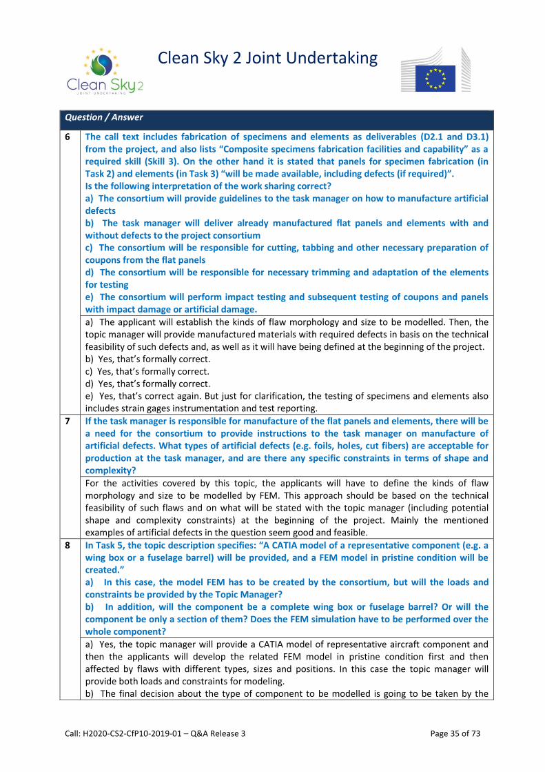
Clean Sky 2 Joint Undertaking
Call: H2020-CS2-CfP10-2019-01 – Q&A Release 3 Page 35 of 73
Question / Answer
6 The call text includes fabrication of specimens and elements as deliverables (D2.1 and D3.1) from the project, and also lists “Composite specimens fabrication facilities and capability” as a required skill (Skill 3). On the other hand it is stated that panels for specimen fabrication (in Task 2) and elements (in Task 3) “will be made available, including defects (if required)”. Is the following interpretation of the work sharing correct? a) The consortium will provide guidelines to the task manager on how to manufacture artificial defects b) The task manager will deliver already manufactured flat panels and elements with and without defects to the project consortium c) The consortium will be responsible for cutting, tabbing and other necessary preparation of coupons from the flat panels d) The consortium will be responsible for necessary trimming and adaptation of the elements for testing e) The consortium will perform impact testing and subsequent testing of coupons and panels with impact damage or artificial damage.
a) The applicant will establish the kinds of flaw morphology and size to be modelled. Then, the topic manager will provide manufactured materials with required defects in basis on the technical feasibility of such defects and, as well as it will have being defined at the beginning of the project. b) Yes, that’s formally correct. c) Yes, that’s formally correct. d) Yes, that’s formally correct. e) Yes, that’s correct again. But just for clarification, the testing of specimens and elements also includes strain gages instrumentation and test reporting.
7 If the task manager is responsible for manufacture of the flat panels and elements, there will be a need for the consortium to provide instructions to the task manager on manufacture of artificial defects. What types of artificial defects (e.g. foils, holes, cut fibers) are acceptable for production at the task manager, and are there any specific constraints in terms of shape and complexity?
For the activities covered by this topic, the applicants will have to define the kinds of flaw morphology and size to be modelled by FEM. This approach should be based on the technical feasibility of such flaws and on what will be stated with the topic manager (including potential shape and complexity constraints) at the beginning of the project. Mainly the mentioned examples of artificial defects in the question seem good and feasible.
8 In Task 5, the topic description specifies: “A CATIA model of a representative component (e.g. a wing box or a fuselage barrel) will be provided, and a FEM model in pristine condition will be created.” a) In this case, the model FEM has to be created by the consortium, but will the loads and constraints be provided by the Topic Manager? b) In addition, will the component be a complete wing box or fuselage barrel? Or will the component be only a section of them? Does the FEM simulation have to be performed over the whole component?
a) Yes, the topic manager will provide a CATIA model of representative aircraft component and then the applicants will develop the related FEM model in pristine condition first and then affected by flaws with different types, sizes and positions. In this case the topic manager will provide both loads and constraints for modeling. b) The final decision about the type of component to be modelled is going to be taken by the

Clean Sky 2 Joint Undertaking
Call: H2020-CS2-CfP10-2019-01 – Q&A Release 3 Page 36 of 73
Question / Answer
topic manager. The topic manager will inform the applicants about this choice at the beginning of the program. In such as circumstance, it will be established which kind of full component or its portion has to be modelled during the project. Consequently, the respective FEM simulation will be finalized on this choice.
9 Although NASTRAN/PATRAN capabilities are requested, could ABAQUS be used as an alternative (or at least supporting) simulation tool?
See point 3 of this section.
10 Could you provide the size or the preliminary geometry of the subcomponent and full scale components? Could be described the type of mechanical testing to be performed in the full scale component?
Note: the applicants won’t perform any mechanical tests on the reference subcomponent and component, but only virtual testing. The size and geometry of subcomponent will be defined at the beginning of the project, but as a preliminary issue we are thinking about a linear composite panel having an approximate size of 1 by 1 meter with more than one stringer. The same considerations are worth for the reference full scale component, but as a preliminary issue we are thinking about either a wing structure or a fuselage barrel, or again a section/portion of them. As a reference for fuselage testing, we have pressurization tests with additional payloads for example, while for wing testing, we could consider representative aerodynamic loads (bending and torsion mainly) for example.
11 Should coupon specimens content all the defects simulated inside the geometry?
The specimens will be tested to validate developed models (just described into task 1), to be decided by the applicant. Surely, they must contain all required defects for the validation (generally one defect per specimen).
12 Will be the SHM software employed in task 34 provided by the topic manager? If yes, should be the software modified/adjusted or only used?
The SHM software is to be employed in task 4 and 5. It will be provided by the topic manager to applicants and to be ready for application. No modification/adjustment is required. The software should be only used.
13 The text refers to specimen / elements / sub-structures. Are there any representative examples of these to get an idea?
Typical specimen: a standardized sample cross-section with two shoulders and a gage section between. Typical element: a stringer, a panel with a single stringer. Typical sub-component: a flat stiffness panel with 3 or 5 stringers.
14 The ultimate goal, in-flight SHM and damage severity / action evaluation seems to require massive efforts to be achieved. Is there any way we can reduce this scope to a particular (small) structural member in combination with a particular SHM technique?
In-flight SHM is the overall pursued goal, but here I can only answer to question focused on the topic description. I am not able to discuss about arguments were not included in this topic.
15 LEONARDO will provide their own software for iFEM; the applicants are called to augment it with data and procedures. What is exactly asked from the applicants? Knock-down factors? Decision on which inverse analysis method? CZM, progressive failure criteria, SERR?
LEONARDO software will be provided for the required activities. The applicants will only have to use this software to process the FEM outputs (produced by the applicants) in order to obtain diagnostic flaws definition for the different flaw morphologies and sizes implemented into the subcomponent and component F.E. models.
16 As correctly indicated in the text, for in-flight SHM, the loads are the big unknown. The text

Clean Sky 2 Joint Undertaking
Call: H2020-CS2-CfP10-2019-01 – Q&A Release 3 Page 37 of 73
Question / Answer
indicates the incorporation of neural networks (in essence learning algorithms) to estimate these loads. The point is that the (already noisy) SHM -> damage coupling noise will be amplified by the stochastic load estimation. At the end, do we still have enough determinism in the system for representative estimations?
The topic description doesn’t deal with load estimation in-flight condition by neural networks. In addition the artificial neural networks used by Leonardo software work only on the strain field modification induced by flaws. Again all needed loads will be provided by topic manager and so they will not be estimated by applicants.
17 If we assume well-defined test and simulation work on specific types of components, then there are some approaches that could work within the set timeline. So if we focus on the testing and analysis of damaged specimen (including life prediction), we see possibilities for a work package that fits our resources and roadmap. Is such a reduction regarded as contributing and, if yes, is there any consortium for which our activities will form a nice complementary effort?
The discussion of other SHM approaches is off-topic. The role of the topic manager is to provide clarifications on the activities included into the topic description. Besides any modifications about the proposal scheduling is not allowed.
On Topic: JTI-CS2-2019-CFP10-REG 01-19 - “Innovative Noise Generation System for testing of Regional Cabin Interior Noise reduction”
1 Number of loudspeakers?
We expect at least three rows of loudspeakers to ensure variable distribution of sound in axial direction. The circumferential number of loudspeaker should be determined by their size in order to accommodate the maximum number of loudspeaker to cover all the fuselage (see requirement m)
2 Desired size of loudspeaker?
Depending on the available technology to satisfy the requirement m. The use of Innovative loudspeakers is strongly recommended.
3 Bandwidth of the loudspeakers (... Hz - ... Hz)?
44Hz- 11.200Hz
4 Requirement of 130 dB SPL: measured where and with which signal and in which bandwidth?
The OASPL shall be measured on the fuselage surface in front of each loudspeaker.
5 On page 164, Task 1 is stated that: “The target is to implement an innovative closed control loop with control strategies in order to reduce this time to less than half a day.”
In order to clarify the mentioned statement: The actual system is an open loop control. The sound profile on the fuselage skin is assigned manually then is generated and then is measured by external microphones on the fuselage skin. Based on these results the initial input profile is adjusted manually and the process is iterated manually until the target profile is reached. This typically takes one week. With innovative closed control loop with control strategies we expect to automate this process so to reduce this time to less than half a day.
6 What are the control objectives or controlled variables?
Control objective is to reduce the difference between the target and the measured SPL (typically< 0.5dB) for each 1/3 octave band. The controlled variable is the SPL over each 1/3 octave band.
7 Are wave fields for TBL or turboprop noise available?
Yes, they will be available at the beginning of the project during the KOM.

Clean Sky 2 Joint Undertaking
Call: H2020-CS2-CfP10-2019-01 – Q&A Release 3 Page 38 of 73
Question / Answer
8 On page 165, it is stated that: “The Sound Waveform Generation and Acquisition subSystem (SWGAsS) will be compatible with the platform that is currently used for the DAQ in Leonardo acoustic laboratory (24bit ADC, 92kHz bandwidth, 150 db dynamic range).” What kind of interface to the Leonardo DAQ is available?
The platform currently used for the DAQ in Leonardo acoustic laboratory is based on the Siemens SCADAS hardware. The applicant needs to provide a suitable interface.
9 On page 164, top it is stated that: “The iNGS will be designed to be used on Clean Sky composite fuselage of 3.45m diameter, but will be adaptable to any fuselage diameter and type.” What are the desired max and min for the fuselage diameter?
Minimum diameter is 2.5m maximum is 4m.
On Topic: JTI-CS2-2019-CFP10-REG 02-06 - "SHMS and Dynamic fields sensors development"
1 Can you give examples of the wired sensors that are currently used in the SHMS (manufacturer, model)?
2 a) What is the meaning of A/C digital bus acquisition for usage monitoring?
b) If this data is provided in the aircraft communication bus, then it is available for the SHMS without further wireless transmission?
c) If wireless transmission is necessary for the digital bus, please explain why and describe the context.
a) The acquisition of existing aircraft bus information i.e. ARINC429, AFDX, 1553B, etc. and the later use in usage monitoring, i.e. fatigue monitoring.
b) The bus could be captured in a remote position by a remote bus sniffer, and the data sent wireless to a central unit.
c) The context could be varied, two examples:
•Future Development of wireless LRUs that work without wires, providing bus data in a wireless way.
•Installation of SHM systems in already built A/C where it is not possible to add the wired routing.
3 Should the energy harvesting system be embedded in the structure? Can multifunctional

Clean Sky 2 Joint Undertaking
Call: H2020-CS2-CfP10-2019-01 – Q&A Release 3 Page 39 of 73
Question / Answer
composites be considered?
NOT for both questions above.
4 In the call text it is mentioned different events and diagnosis. Is it requested to have experience and knowledge on all of them?
NOT in the event and damage Diagnosis by itself, but YES in the sensors needed to generate the data to feed such an event and damage Diagnosis SHM system.
5 Is it mandatory to have experience in all the directives mentioned in the proposal?
NOT for all. YES for DEF-STAN 00-970 Part1 Sect3, SAE-ARP-6461, MIL-STD-704 and DO-160.
6 Are the frequency bandwidth and transmission bandwidth indicated in the call text a requirement? Or an example?
They are typical bandwidths to indicate the working time scale of sensors.
7 Is flight test experience mandatory?
NOT in flight test, but YES for material qualification for flight test.
8 The short description of the topic mentions “[...] with incorporated data acquisition and processing”, but later it is not explicitly mentioned in the WP breakdown. Should the required flight system include both aspects (Data Acquisition and Processing)?
YES, it will be necessary the processing capabilities, see page 2, “aim of this topic” paragraph.
9 Is it requested to develop/validate SHM techniques in the qualification tasks?
NOT, see page 2, qualification of sensor functionality (acquisition, processing, wireless transmission and harvesting capabilities assurance).
10 Should the sensor qualification task be oriented to damage detection or measurement and resistance under operation conditions?
NOT, the sensor qualification task is oriented to ensure the selected sensor functionality assurance for the typical aircraft environmental and operational conditions. See previous question.

Clean Sky 2 Joint Undertaking
Call: H2020-CS2-CfP10-2019-01 – Q&A Release 3 Page 40 of 73
III. Fast Rotorcraft IADP
Question / Answer
On Topic: JTI-CS2-2019-CFP10-FRC 01-28 – "Innovative kinematic analysis to incorporate multiple
functions within a movable surface"
N.B. JTI-CS2-2019-CFP10-FRC-01-28: The topic is contributing to the action as planned into FRC - WP 1.4 of the CS2 JTP 2015 (instead of WP 1.2.2 as indicated into the topic front page)
1 Is the study of a unique movable surface to allow the different functions of a flap and of a flaperon a mandatory objective of this topic or could a solution involving multiple aerodynamic movable surfaces guided by a smart single actuation system be investigated or encouraged?
The concepts under investigation shall overcome the need to have, as described in Background chapter, two separated movable surfaces (with respect to the fixed part of the wing) on each wing semi-span allocating specific functions. Technical solutions using either single or multiple actuations systems can be developed by the applicants on the basis of the requirements (defined at the beginning of the project under WP1) and also considering reliability and failure aspects.
On Topic: JTI-CS2-2019-CFP10-FRC 01-29 - “Smart Active Inceptors System development for Tilt Rotor application”
N. B. JTI-CS2-2019-CFP10-FRC-01-29: The topic is contributing to the action as planned into FRC - WP 1.6 of the CS2 JTP 2015 (instead of WP 1.2.3 as indicated into the topic front page)
1 The pilot and co-pilot pedals have a mechanical link, but are they active (do they have an electric motor) or passive (with a spring)? In any case, it is understood that proper sensing means are used in order to transmit the information of the pedal position to the FCC.
Every inceptor being part of the system, including pedals, shall have active feel, intended as the capability to provide force feedbacks / tactile cueing. Hence, pedals are expected to be active.
It is well understood the requirement to provide position information to the FCS.
2 In the case of using electric motors, would all the programming parameters applied to the sticks and sent to the FCC in real time be applicable? (Variable spring, gradient force breakouts, shaker, etc.).
At this stage, it can be assumed they are all applicable.
As stated in the call text, “a preliminary system specification will be provided at starting of activities. The definitive specification will be issued within following 6 months”.
This is due to preliminary activities aimed at defining the system, including the functionalities to be implemented within pedals and hence the parameters to be applied, being carried as part of a previous CleanSky2 call (JTI-CS2-2018-CFP09-FRC-01-25) which will be completed after the start of this call.
3 Is the left pilot/co-pilot inceptor (equivalent to the collective lever of a helicopter) considered single axis or dual axis?
At this stage, a frozen configuration cannot be assumed. A preliminary indication will be given at the beginning of the activities.
As stated in the call text, “a preliminary system specification will be provided at starting of activities. The definitive specification will be issued within following 6 months”.
This is due to preliminary activities aimed at defining the system, including left-hand inceptor ergonomics and degree of freedom, being carried as part of a previous CleanSky2 call (JTI-CS2-

Clean Sky 2 Joint Undertaking
Call: H2020-CS2-CfP10-2019-01 – Q&A Release 3 Page 41 of 73
Question / Answer
2018-CFP09-FRC-01-25) which will be completed after the start of this call.
Please note that left-hand inceptor is unique to tiltrotor and is not equivalent to a helicopter collective lever.
4 Which is the exact definition of “hard-stop”? Is it still a “soft-stop” with a higher force range, or is it a mechanical stop adjustable in real time by the FCC?
As per ARP5764, a “hard-stop” can be considered as “soft-stop”, but with the gradient across the hard-stop as high as possible in order to provide a simulated mechanical end stop to the pilot.
5 In the text it is mentioned that “A second bus protocol has to be considered”. Does this refer to a possible alternative to AFDX or to a back-up bus in parallel with the AFDX?
AFDX will be the main protocol, a second bus would be a backup/parallel bus.
6 Does inceptors shipset include pilot and copilot pedals with active feel although it is clearly stated that pedals shall be mechanically linked?
Yes, every inceptor being part of the system, including pedals, shall have active feel. For pedals, since they will be mechanically linked, there is no need to simulate a mechanical linkage; yet, active feel is intended as the capability to provide force feedbacks / tactile cueing.
7 Task 1 description states the following: “This activity does not include left-hand inceptor design”. Shall it be considered that the design for this inceptor already exists? Are the kinematics and number of axes for LH & RH inceptors defined? Any preliminary assumption to be considered in order to refine the scope for the proposal?
The mentioned statement in Task 1 description refers to activities related to left-hand inceptor ergonomics design. Design of left-hand inceptor ergonomics is out of scope of this call and will be part of the overall system requirements. Task 1 will cover all activities aimed at Preliminary Design Review of the whole Active Inceptor System, including HW/SW design for left-hand inceptor.
No further detailed assumptions can be provided at this stage. As stated in the call text, “a preliminary system specification will be provided at starting of activities. The definitive specification will be issued within following 6 months”.
This is due to preliminary activities aimed at defining the system, including inceptors’ ergonomics and degree of freedom, being carried as part of a previous CleanSky2 call (JTI-CS2-2018-CFP09-FRC-01-25) which will be completed after the start of this call.
On Topic: JTI-CS2-2019-CFP10-FRC 01-30 – "Multipurpose bench for Tiltrotor equipment functional test"
N.B. JTI-CS2-2019-CFP10-FRC-01-30: The topic is contributing to the action as planned into FRC - WP 1.6 of the CS2 JTP 2015 (instead of WP 1.3 as indicated into the topic front page)
1 Could you provide the list and a summary of the existing Functional Test Procedures and existing hardware used to perform the tests?
The list to be processed by the Multipurpose bench will be defined in the final tech. Spec. as part of the project.
As reference, the applicant should consider Functional Test Procedures related to Hydraulic, Fuel, Dynamic System, ECS
- Digital Multimeter
- Variable frequency waveform

Clean Sky 2 Joint Undertaking
Call: H2020-CS2-CfP10-2019-01 – Q&A Release 3 Page 42 of 73
Question / Answer
- Power & Signal switches
- AC/DC Voltage – Current
- Controller
2 Could you provide the architecture of the Electric Power Generation and Distribution System with electric characteristics (power, voltage, current) and type/number of I/O interfaces?
Architecture cannot be shared at this phase.
Main electric characteristics are 0 to 50 Vdc, 0.1 V scale and resistance from 0 to 20MΩ.
Concerning Interfaces, approximately 300 points should be considered by the applicant.
3 Could you provide the architecture of the electro avionic system?
Not shareable at this phase.
4 Annex VI 10th Call for Proposals (CFP10) – p. 192: Could you precise what do you expect in the Task 8 Phase 2: Development of Multipurpose FTP Test Bench (16 months duration)?
The design and manufacturing of Multipurpose FTP bench after the design phase (20 months duration) and its delivery and acceptance.

Clean Sky 2 Joint Undertaking
Call: H2020-CS2-CfP10-2019-01 – Q&A Release 3 Page 43 of 73
IV. Airframe ITD
Question / Answer
On Topic: JTI-CS2-2019-CFP10-AIR 01-41 - "Low speed handling quality and innovative engine
integration of a new configuration aircraft" 1 Ref Cap 1 “Background” –It is indicated that the “new configuration will be based on an existing
wing. The wing scale is 1/10 with mean aerodynamic chord equal to 0.25 m and spanwise length equal to 2.5 m (full span)”. But the planform of the wing presented on Figure 1. is representative of a “half wing”. So please confirm that a 3D model, (not a “half span model”) is requested. An overall pictures of the complete configuration to be tested will be appreciated. It is a full span 3D model. Please find below an illustration of the type of configuration that could be tested.

Clean Sky 2 Joint Undertaking
Call: H2020-CS2-CfP10-2019-01 – Q&A Release 3 Page 44 of 73
Question / Answer
2 Ref Cap 2 “Scope of work” – Various sets of model parts (HTP. VTP. Fuselage nose, etc.) have to be realized by using ALM techniques. Could you please give more information about dimensions of the requested parts?
Size of fuselage forebody is approximately 0.4 m x 0.3 m x 0.4 m (model scale 1/10). HTP size is approximately 0.8 m (full span) and chord length equal to 0.25 m. It can be manufactured in twice. VTP size is approximately 0.4 m (height) and chord length equal to 0.4 m.
3 Ref Cap 2 “Scope of work” – two sets of nacelles are required to be “transparent”. Could you give more information about: a.)The loads expected to be acting on the nacelles; b) Mass flow rate to be required for air intake simulation.
Two sets of nacelle : 1) Through flow nacelle translated by “transparent” in the topic description. 2) Mass flow simulation up to 1.2 kg/s (model scale 1/10) Loads on nacelle are not available yet.
4 Ref Cap 1 “Background” and cap 2 “Scope of work” – in cap. 1 you wrote: “Interaction between fuselage and engine will be analyzed during wind tunnel tests: o Distortion will be measured in the nacelle inlet with a rake…. (omissis) o PIV will be used to visualize the flow interaction between the nacelle and the fuselage o Visualization of pressure distribution on the fuselage will be performed by using PSP measurement technique" Please confirm that no other measurement techniques (i.e. pressure taps) are required. Otherwise, could you define the requirements for model instrumentation?
Instrumentation will be composed of : 1) Balance measurement for forces and moments 2) At least one inclinometer for AoA measurement. 3) some strain gauges on HTP and VTP (one or two by element : to be confirmed) 4) some pressure taps (location to be defined, approximately 20 pressure taps are necessary at maximum on fuselage) 5) The applicant shall suggest innovative visualization means including PSP and PIV. The model will be supported by a ventral strut.
On Topic: JTI-CS2-2019-CFP10-AIR 01-42 - "Development of a methodology (test, measurement, analysis) to characterize the behaviour of composite structures under dynamic loading"
1 Is consortium of three different applicants from three European countries required for this topic or it would be enough if the Ukrainian companies’ consortium only applies to?
Please refer to sections 10 and 11 of the Q&A document (at the beginning of the document).
2 What is the procedure for obtaining the inputs?
Inputs will be provided by the topic manager at the beginning of the project (T1).
3 What damages to be considered in the project? Cracks, delaminations? Should the kind of damage be derived from the project or it should be specified by the Topic Leader?
Damages to be considered will be mostly fracture and delamination. Inputs will be provided by the topic manager in T1, discussed and agreed with the applicant.
4 Could we obtain information on dimensions and structure of test demonstration in order to estimate cost of manufacturing and modifying of additional tooling and jigs for testing?
This topic will be discussed and agreed with the topic manager in more details in T2. Nevertheless,

Clean Sky 2 Joint Undertaking
Call: H2020-CS2-CfP10-2019-01 – Q&A Release 3 Page 45 of 73
Question / Answer
foreseen tests are limited to the element level of the classical test pyramid. Dimensions should range approximately from small coupons (~10mmx100mm for tension) up to intermediate assemblies of stiffened plates (~500mmx500mm).
5 Are there models of behaviour for the carbon plastic to which we should be oriented to?
There is no requirement in terms of model to be used. This will be discussed and agreed with the topic manager in the frame of T1.
6 What is the tolerance of complying numerical and experimental data?
Characterizing and quantifying compliance between numerical and experimental data is an objective and output of the project. There is therefore no a priori specific requirement.
7 What are the requirements for the work plan?
The work plan should describe tests (samples, test setups, test conditions, instrumentation etc.) and numerical analyses (methodology, tools, identification process etc.) planned to be performed in the following tasks to meet the overall objectives of the CfP. The work plan should state the associated manufacturing, testing and analyses planning and organization in concordance with the CfP duration.
8 What is meant under “industrial needs”?
The ability to apply the proposed methodology in an industrial context : - evaluation/validation on representative structures (thickness, stacking sequence, assemblies etc.) under representative loadings (strain levels and rates), - and modelling cycle (characterization, modelling, computational cost etc.) compatible with an industrial application.
9 Bird impact element is needed for the tests. Should the parameters of this element be specified by the Topic Leader or they are to be derived from the Project?
Bird impact modelling is not required for this project. It is mentioned as a possible application to orient the application of the methodology and tests.
10 Shall modelling method be implemented in ANSYS or NASTRAN?
There is no requirement in terms of numerical tools to be used.
11 Are there some criteria to choose techniques of test and specimen shape and size?
There are no specific requirements but the compliance with the objectives, planning and costs. This will be discussed and agreed with the Topic manager.
12 What is the procedure for acquiring, supplying and paying the materials for test specimen manufacturing?
The supply and payment of materials for the test specimen manufacturing will be supported by the Applicant.
13 Who does purchasing the material and is its price included in the specified cost of the topic?
The Applicant will be purchasing the material and its price is included in the specified cost for the topic.
14 What is the procedure for test specimen manufacturing?
The manufacturing process will be specified by the topic manager in the scope of task 4. Manufacturing of the specimen is under the responsibility of the Applicant.
15 What are the requirements for certification of test equipment and means of control and measurement?
Standard Verification and Validation procedures should be applied.
16 What is the volume of tests?
This has to be defined in task 2 as it is linked to the proposed methodology.
17 What to do with test specimen after testing?

Clean Sky 2 Joint Undertaking
Call: H2020-CS2-CfP10-2019-01 – Q&A Release 3 Page 46 of 73
Question / Answer
Test specimen should be stored until the end of the project and may then be destroyed.
18 What speeds of throwing and deformation are of the Topic Leader’s interest?
Application objectives will be discussed at the beginning of the project with the Topic manager but are limited to intermediate velocity impacts (~100-200m/s) generating strain rates in the order of magnitude of 100s-1.
19 Shall be presented static parameters of material and its static test data (deformation curves)?
If needed, static parameters may also be addressed in the test matrix.
20 Is it mandatory to have assembly zones (for example bolts and rivets) in the panel structure? If yes then it is needed to specify parameters of such joints.
Yes, assembly zones are of interest in the project and will be studied. Inputs will be provided by the topic manager and discussed at the beginning of the project.
On Topic: JTI-CS2-2019-CFP10-AIR 01-44 - "Development of a methodology to optimize a wing composite panel with respect to tyre damage certification requirement"
1
Is consortium of three different applicants from three European countries required for this Topic or it would be enough if the Ukrainian companies’ consortium only applies to?
Please refer to sections 10 and 11 of the Q&A document (at the beginning of the document).
2
What is the procedure for obtaining the inputs on: • a few configurations of reference (materials and manufacturing processes, general panel geometry with supporting substructure, typical loading and environmental conditions of the panel, existing panel configurations, layup and thicknesses including stiffeners); • impact conditions (impactor definition, velocity, etc.); • a framework for definition of methodology?
Configurations of reference and impact conditions will be indicated by the topic manager as an input at the beginning of the project. There is no specific framework for the definition of methodology, but this should be discussed in the frame of WP1 with the topic manager.
3 Will the Applicant obtain data on the stress-strain state and strength parameters in numerical cases of loading (this information is needed for test specimen design)?
Based on the reference configurations and impact conditions provided, these parameters may be investigated by numerical analysis by the applicant. These data will be shared and agreed with the topic manager to specify test specimen design and setup.
4 What are the requirements for the work plan?
The work plan should describe tests (samples, test setups, test conditions, instrumentation etc.) and numerical analyses (methodology, tools, identification process etc.) planned to be performed in the following WP to meet the overall objectives of the CfP. The work plan should state the associated manufacturing, testing and analyses planning and organization in concordance with the CfP duration.
5 Shall modelling method be implemented in ANSYS or NASTRAN?
There are no requirements in terms of numerical tools to be used.
6 What is the procedure for the supply and payment of materials for test specimen manufacturing?
The supply and payment of materials for the test specimen manufacturing will be supported by the applicant.
7 Who does purchasing the material and is its price included in the specified cost of the topic?
The applicant will be purchasing the material and its price is included in the specified cost for the topic.
8 What is the procedure for test specimen manufacturing?

Clean Sky 2 Joint Undertaking
Call: H2020-CS2-CfP10-2019-01 – Q&A Release 3 Page 47 of 73
Question / Answer
The manufacturing process will be specified by the topic manager in the scope of WP1 tasks. Manufacturing of the specimen is under the responsibility of the applicant.
9 What are the requirements for certification of test equipment and means of control and measurement?
Standard Verification and Validation procedures should be applied.
10 What is the volume of mechanical tests?
This has to be defined in WP1 for elementary and flat panel tests as it is linked to the proposed methodology. One validation test on a stiffened panel is required in WP4.
11 What to do with test specimen after testing?
Test specimen should be stored until the end of the project and may then be destroyed.
12 Are there special requirements for instrumentation supply?
No.
13 Who is meant by OEM?
Dassault Aviation.
14 What is the procedure of large panel manufacturing?
The manufacturing process will be specified by the topic manager in the scope of WP1 tasks. Manufacturing of the specimen is under the responsibility of the applicant.
On Topic: JTI-CS2-2019-CFP10-AIR 02-77 – “Increasing the efficiency of pulsed jet actuators for flow separation control"
1 What are the page limits?
I guess the questioner is referring to page limit of the proposal. Forthis and former calls, there is a limit of 70 pages for Part B.I (see call instructions).
2 Do we need separate actuators for the individual jets or we can a single one to drive the multi-jet configurations?
There is a request for geometrical variations of the pulsed jet actuator, comprising a variation of the spacing between the pairs of jets and a variation of the aspect ratio of the blowing slots (defined in Task2). There are no requirements for separate actuators for the individual jets; however the system has to work properly while changing the configuration (variation of the spacing between the slots and of the aspect ratio of the slot geometry).
3 What are the baseline dimensions of the jets slots/width/height?
The dimensions of the baseline slots are in the range of (3mm/0,5mm, width/height). The final dimensions of the slots will be defined in accordance with the real dimension of the wind tunnel model to be used. The aspect ratio of the slots shall be adjusted during the tests between 3 and 6 (see Task2).
4 What is the flap deflection angle range?
There are no specific requirements.
5 Is there an aerofoil preference?
No, there is no preference for an airfoil.
6 What is the preferred incidence range?
The incidence angle shall start in the lower part of the linear alpha/Cl region and shall exceed the stall angle by 3 degrees (with AFC on). It shall be considered that the stall angle will increase when AFC is switched on.
7 Are there any constraints to scale-up or down the proposed PJA device?
The dimensions of the baseline slots are given in the answer to Question 3. There is no up-scaling or down-scaling of the PJA device foreseen aside from a slight adaption to the real dimensions of the wing model.

Clean Sky 2 Joint Undertaking
Call: H2020-CS2-CfP10-2019-01 – Q&A Release 3 Page 48 of 73
Question / Answer
8 The call asks the applicant to manufacture new pulsed-jet actuators with aspect ratios between 3 and 6. This is an order of magnitude smaller than for typical pulsed-jet actuators. Are the values written in the call correct or is this a typo?
Yes, the required values for the aspect ratio are correct. The values of the aspect ratio used for pulsed-jet actuators may vary, but are usually not higher than 10 (often 6 to 10).
9 What is the pulsing frequency range required?
The pulsing frequency shall ensure an oscillating nondimensional frequency of F+=1 to 3 (range of 300Hz to 1kHz).
10 The first task of the call CFP10-AIR-02-77 mentions an “existing wind tunnel model”. Will that model be provided by the topic leader? Or the applicant must own that model?
The wind tunnel model must be owned by the applicant. There is no specific request for the profile of the wind tunnel model. Therefore the applicant shall use an “existing wind tunnel model” at the disposal of the applicant.
11 What kind of information will be given about the baseline PJA system (CAD, design point, …)?
There is no CAD available for the baseline PJA. The applicant shall have experience with the design and manufacturing of pulsed jet actuators. The pulsing non-dimensional frequency shall be in the range F+=1 to 3, the Ma number of the jets shall be adjustable between Ma = 0.4 and 0.9. There will be provided during the negotiation phase information about the PJA already used in other research projects.
12 Which chord is associated to a 3mmx0.5mm slot?
The chord of the wing will be defined by the requested Ma number of the free stream flow (between 0.1 and 0.2) and the Reynolds number related to the Mean Aerodynamic Chord (MAC). The Re number shall be higher than 1 Mio (please see also the specifications given in the Call). The final dimensions of the PJA slots will be adapted to the corresponding used wing chord. Final details about the PJA will be clarified during the negotiation phase.
On Topic: JTI-CS2-2019-CFP10-AIR 02-78 – “Application of graphene based materials in aeronautical
structures for de-icing, lightning strike protection, fire barrier and water absorption prevention
purposes”
1 Is there a specific type or form of demonstrator desired (wing leading edge, tail leading edge, etc.)?
A dedicated demonstrator has been selected for each type of Graphene Based Material (GBM) application. In particular for: - Task 3 (lightning strike applications) a simplified Horizontal Stabilizer or fuselage panel has been selected as small demonstrator -Task 4 (fire barrier applications) a small scale test article, representing a simplified bulkhead panel shall be manufactured and tested -Task 5 (coatings for water absorption barrier) a small epoxy laminate and a small sandwich structural panel shall be manufactured and tested -Task (de-icing system) a simplified curved leading edge (L = 400 mm, W = 200 mm approx.) with embedded de-icing system shall be manufactured and tested.
2 In task 2, mention is made of demonstrating resistance to impact/damage. Are there specific tests/impacts that are envisaged, or is it up to the coordinator of the project to propose something?
In task 2 it’s stated that the functional properties of graphene based material shall be assured also after damages like scratches or hail impact. It’s not mentioned that the GMB has to improve its

Clean Sky 2 Joint Undertaking
Call: H2020-CS2-CfP10-2019-01 – Q&A Release 3 Page 49 of 73
Question / Answer
resistance to impact. Typical dimension of small damages caused by hail impact (BVID – Barely Visible Impact Damage) on aeronautical structures are with an indentation of 0.8-1 mm.
3 On the one hand, it is mentioned that the proposed solutions shall ensure the integration/embedding of the desired system and/or of the functionality into the composite material constituent of the aeronautical components. On the other hand, it is also mentioned that the new graphene-based material (GBM) will be coupled with the epoxy and aluminum. The question is if the new GB should be applied as a coating (by spraying) or a laminated layer. What is the desired application method?
The object of the call for proposal is to investigate possible advantages of GBM (de-icing, fire barrier, water absorption barrier, lightning strike) and its best way of application in the aeronautical structure. So in some cases the material could be used as coating or external layer (e.g. de-icing or lightning strike protection) in other cases it can be integrated as additive in the thermosetting resin of composite material of the structure (e.g. fire barrier or water absorption protection). The applicant it’s requested to study and propose the best way to exploit the potentiality of graphene for all or part of proposed applications.
4 For the de-icing application, the new GBM (as circuit) should be an intermediate layer of the final sandwich-structured composite. For the lightning strike protection, the new GBM should be the outer layer. In Task 6, it must be demonstrated the multifunctionality of the de-icing system (de-icing/lightning strike protection). Can you clarify if it should be a multifunctional layer or a multilayer composite in which each layer has a specific functionality?
See answer #3 In addition: According to the peculiar application, the GBM can be integrated in the structure as additive of thermosetting resin or applied as external layer. It depends upon the capability/knowledge of the applicant to select the best way to exploit GMB potentialities.
5 To what extent do the control systems for the deicing module need to be developed?
Our need is to investigate the potentiality of GBM for de-icing application and also its integration in a real aeronautical structure. For this reason also the control system has to be developed in order to allow: activation / deactivation of de-icing system, power regulation, monitoring of the reached temperatures to avoid overheating of the structure.
On Topic: JTI-CS2-2019-CFP10-AIR 02-79 – “Development of FEM fastener parametric/adaptable sizing tool including EMC impact, and manufacturing and EMC/LSP testing of demonstrators"
1 Do you have a standard for DEOL and HIRF tests? If not, do you have any established requirements: frequencies, parameters to evaluate, etc.?
Basic standards and requirements placed on demonstrators and both the CFRP-metal and the CFRP-CFRP joints are governed by requirements and recommended practice applied on a specific part of the EV-55 aircraft (CNP demonstrator). Detailed description of the tests will be discussed in the deliverable D-B-3.4.2-7. The main objective is to confirm compliance with certification requirements described in CS-23 (23.867, 23.1306, 23.1308; requirements applicable for the demonstrator). All the tests (frequencies, test waveforms, levels of currents and fields, etc.) shall be in line with standard acceptable means and practices described in: AMC 20-136, AMC 20-158, ARP 5577 (ED-113), ARP 5416 (ED-105), ARP 5412 (ED-84), ARP 5413 (ED-81), ARP 5415, ARP 5583 (ED-107), AC 20-107, AC 20-136, AC 20-158, AC 20-53. The required outputs will be in line with a standard scenario: current / voltage transients, resulting E/H fields, damage evaluation (severity and type of damage found on a test subject), etc.
On Topic: JTI-CS2-2019-CFP10-AIR 02-80 – “Innovative flight data measurements to support the
aerodynamic analysis of a compound helicopter demonstrator”
Clean Sky 2 Joint Undertaking
Call: H2020-CS2-CfP10-2019-01 – Q&A Release 3 Page 50 of 73
Question / Answer
1 Are there any specific aerodynamic requirements for the flight test instrumentations?
The systems installation shall be as non-intrusive as possible from aerodynamic point of view and without impacting the structure. Depending on their position, some sensors may be ingested or blown by air openings. To avoid this, the partner shall provide the relevant information regarding the risk of sensor snatching (example in case of adhesive sensor: force/pressure for ungluing, acceptable temperature range and moisture level, sensitivity to lubricants, …). A specific attention to the volume, weight and wiring minimization has to be provided and will be considered for the selection of the system to be developed.
2 The call foresees the measurement of the velocity components at different positions on the test aircraft. It is not clear from the call if the measurement needs to be performed on the helicopter surface (shear-stress vector at different positions on the helicopter solid surface) or away from the surface (velocity vector in free air at a specified distance away from the helicopter solid surface). The distinction is important with regard to the intrusiveness of the measurement system. The shear-stress vector can be measured with surface instrumentation but the velocity away from the surface cannot.
The velocity components need to be measured away from the surface, in the free air, as the interest lays in the generation of velocity cartography that feeds the different elements. On the contrary, the pressure data need to be extracted from surface measurement.
3 Furthermore, it would be of interest to know if the complete measured data needs to be available in real time within the flight test instrumentation. This does change the requirements regarding the bandwidth of the proposed measurement system.
No real time monitoring is requested for this instrumentation; only off-line.
4 Number of probe: a) Such expression “30 probes distributed on 2.5 m span. On inner and outer sides” means 30 probes on each side or 30 probes for the both sides? b) How many probes are required by such expression “with several tens of probes” on the intermediate cowling? c) For inflow characteristics, how many sensors of each kind (velocity components and pressure level) are required? d) For velocity components of the external air flow, how many sensors are required? e) How many temperature and velocity sensors are required for the mapping (12 probes of each)? f) In summary, how many sensors of each kind (velocity components and pressure level) are expected for the whole project?
a) Inner and outer sides for the left and right vertical fins. b) 5 rakes of 10 probes are our previsions. c) Our guess is 3 rakes of 12 pressures probes for skin measurement and around 25 velocity probes for volume characterization. d) Our guess is 8 azimuthal stations with 6 radius stations, upstream and downstream of lateral rotors. e) 12 for each. f) A rough order of magnitude ROM is 1000 pressure and 150 velocity probes. Flexibility of installation is of paramount importance: the probes locations may be modified during tests depending on the investigations and all the addressed areas may not be investigated simultaneously.
5 Instrumentation: The topic mentions to produce and deliver a non-intrusive instrumentation

Clean Sky 2 Joint Undertaking
Call: H2020-CS2-CfP10-2019-01 – Q&A Release 3 Page 51 of 73
Question / Answer
able to be used for flight test. Some solutions exist already for instance the patented one CaptiFlex (www.le-captiflex.fr) that was already tested in flight. Should be these included in the proposal?
If it is compatible with helicopter environment (vibrations, interaction with hot exhaust gas), it can be proposed.
6 Flight duration: a) How long is the maximum duration of flight? b) How many flights will be performed each day? For the flight campaign? c) How long is the flight test campaign?
a) max 2 hours b) 1 flight/day c) The presented planning includes the end of the test campaign: M+36
7 Synchronization: What is the clock for synchronisation?
We rely on the standard FTI clocking. For frequency up to 512 HZ, the recording duration is the whole flight test duration; for greater frequencies, the recording duration can be limited.
On Topic: JTI-CS2-2019-CFP10-AIR- 02-81 - "Active Flow control on Tilt Rotor lifting surfaces"
1 On page 254, it is written : “This synthetized effect, i.e. reduced order model to be implemented through the use of User Defined Function (UDF) into the CFD solver, shall be yet available at the Applicant (with proof of methodology validation) and applied to the specific problem of the Tilt Rotor.” Can you please reply to the following questions: a. Is a specific solver mandatory to bid, or can the bid put a solver forward? b. If applicants have synthetic jet effects, momentum sources, and models for ZNMF devices, which are demonstrated for other areas, and also have CFD solvers demonstrated for tilt-rotors are they allowed to bid? c. Even if the above-mentioned sentence is poorly worded and unclear, I am concerned that unless an applicant has demonstrated tilt-rotor wings with ZNMFs is to be excluded. In other words, if an applicant has not studied that very specific combination of flow control and wing in the past, he/she will have no chances of a successful bid. I believe that this sentence should be removed altogether since it may be photographic to certain preferred applicants. Paragraph 4 of the call with the skills and capabilities required is more than adequate.
a. There is not a request for a specific solver. The applicant can use any commercial software or in-house developed tool. The only and obvious constraint is the capability of the solver to manage complex geometrical configurations with the associated flow physics. It’s however recommended to specify the solver characteristics into the proposal. b. Yes c. The quoted above sentence shall read: “This synthetized effect, i.e. reduced order model to be implemented through the use of User Defined Function (UDF) into the CFD solver, shall be yet available at the Applicant (with proof of methodology validation) and it will be then applied to the specific problem of the Tilt Rotor.” It’s then not requested a previous application of this kind of approach to a Tilt Rotor configuration.
On Topic: JTI-CS2-2019-CFP10-AIR 02-83 – “Innovative weight measurement system for Tilt Rotor
application”
1 What are the weight ranges to be considered, i.e. minimum and maximum weight to be measured?
The range to be considered is from 1500Kg to 9000Kg. Considering also the different stages in

Clean Sky 2 Joint Undertaking
Call: H2020-CS2-CfP10-2019-01 – Q&A Release 3 Page 52 of 73
Question / Answer
which during assembly weights will be recorded. The accuracy for each cell must be within +/- 1Kg.
2 What are the dimensions of the aircraft? Is it possible to receive a drawing showing the relevant geometrical sizes in top view and front view?
Length 14800mm Width 12500 (no blades considered) Height 6200 For reference only attached drawing AW609 3 Views :
3 A question regarding the industrial site: Where is it located?
The Leonardo Final Assembly for experimental Aircraft is managed both in Vergiate and in Cascina Costa (20km distance). The final site is not decided yet.
4 In the general requirements, you write “+/-1mm on the aircraft positioning” : • a) Is it information concerning the precision expected on the calculation of the center of gravity? • b) What is the maximum error expected on the calculation of the center of gravity in the

Clean Sky 2 Joint Undertaking
Call: H2020-CS2-CfP10-2019-01 – Q&A Release 3 Page 53 of 73
Question / Answer
horizontal plan and on the vertical axis?
The maximum error of the calculation of the center of gravity is associated to the tolerance accuracy of each cell (+/- 1kg) already stated in the last communication. The result of the calculation of the CoG must be expressed in mm.
5 Regarding the type of weighing system : • a) Will the weighing system be embedded in the ground or mobile (i.e. Out of the ground)? • b) If the system is embedded, who is in charge of civil works?
a) Embedded.
b) Leonardo on the basis of weight measurement system manufacturer indications.
6 Question regarding the helicopter : • a) What is its approximate empty weight and MTOW? • b) What is the approximate distance between front and rear landing gear? • c) The document mentions a repeatability error up to 1 kg but nothing about the acceptable intrinsic error on the total load. What is the precision expected on the total load?
a) Empty weight: 5900-6400Kg MTOW: 8165 Kg. As stated Aircraft weight will be monitored during the different assembly phases.
b) Approx. distance is 5696 mm.
c) As a consequence of the requirement for each cell, will be +/-3kg on the total.
On Topic: JTI-CS2-2019-CFP10-AIR 02-85 – “Development of a multifunctional system for complex aerostructures assembly, assisted by neural network softwares”
1 Is it possible to specify in more detail the deliverable 3.2 “Engineering models”? What models are expected?
Deliverable 3.2 is the support and concurrent to be provided to Topic Manager for the development of the 3D models of the aircraft section/parts that will be used in relevant use case, where mixed reality application is foreseen (structures, wiring, etc.). Design of 3D model is under Topic Manager responsibility.
2 What is expected at point 4.0 Special skills, Capabilities, Certification expected from the Applicant(s), as: Proven experience in aircraft assembly process? It is not a mandatory special skill. Leonardo’s technicians has the experience in aircraft assembly process, the Applicants shall be
able, just to understand the requirements that Leonardo’s technicians will define. On Topic: JTI-CS2-2019-CFP10-AIR 02-86 – “Development of equipment for composite recycling process of uncured material”
1 About the methods for Fiber Areal weight and fiber orientation distribution (task 1.4): a. Have these measurements to be done on un-cured specimens? If yes, have they to be performed only one to time to qualify the developed process and equipment used on a specific prepreg system? Or the measurement has to be done on each batch of recycled material, test can be performed on a single cured panel obtained from the batch? b. Is it necessary to measure Fiber Areal weight and fiber orientation distribution on line on un-cured material?
a. The measurements have to be done on uncured recycled material, one time for each batch produced. b. The FAW and fiber orientation measurements can be made both on line and at the end of the
Clean Sky 2 Joint Undertaking
Call: H2020-CS2-CfP10-2019-01 – Q&A Release 3 Page 54 of 73
Question / Answer
recycled process depending on the method used by the applicant.
2 In task 2.4 it is required production of 500sm at TM site. Where is TM site? Will TM provide to all scraps to obtain 500sm of recycle material in a reasonable time to comply with the call schedule?
TM site is located in Italy at Pomigliano d’Arco (Naples). Yes, the scraps to obtain 500sm of recycle material at TM site will be provided by TM to the applicant in accordance with the agreed schedule.
3 What is the tolerance on fiber orientation?
The fiber orientation tolerance achievable depends on the process that will be developed by applicant and will be jointly agreed during the activities foreseen in the call. A reasonable value to be confirmed is +5°.
4 What is the prepreg areal weight of un-cured material?
The FAW of the prepreg scrap material that will be recycled is about 200 g/sqm.
5 Concerning Intellectual Property related to existing study or system, the call reports “Due to the confidential content of this additional information, it will be necessary to sign a Non-Disclosure Agreement (NDA) with the Topic Manager Company. Questions concerning the confidential data delivered will be handled in a dedicated Q/A document”. What is the procedure to sign NDA?
It’s needed to contact the JU office at this address: mailto: [email protected]
6 Regarding Working flow not exceeding 8h, which are operative steps included?
The 8h period covers all the steps from the defrosting of scrap material up to the final recycled material to be immediately used or put into refrigerator for future use.
7 What is/are the exact patent(s) mentioned in the call?
ES 2367211
8 Is there a defined fiber orientation direction for placing the uncured scrap into the machine before cutting or is the scrap placed randomly distributed into the machine (so the machine has to detect and online calculate the distribution and cutting or has to turn the scrap)? This question should clarify the flexibility of the cutting unit and assure (if necessary) online mapping performance.
In order to obtain the “CFRP chips” with the higher dimension parallel to fiber orientation, two
different cutting steps of prepreg scraps have to be considered. To facilitate this operation could
be convenient to perform firstly transverse cutting respect to fiber direction to obtain 8 mm width
longer strips and then to cut them in smaller pieces (about 50 mm). So scrap materials have to
arrive to the first cutting equipment with fiber direction perpendicular to cutting blades. The
system has to be capable at least to detect scrap fiber orientation in order to verify the above
requirement; could be a good solution to have a system capable also to turn the scrap if needed. For the first prototype, a uniform feed made manually by the operator is allowed (removal of the
separator and aligned arrangement on the table of the scrap with a dedicated device).
9 What is the consolidation process of the created material?
The scrap material is a thermoset type prepreg; recycled material will be consolidated in autoclave (180 °C and 6 bar pressure) by TM and coupons will be extracted and tested by the Applicant.
10 What is the main the fiber orientation of the scrap? Out what kind of fabric is the scrap of? Is it unidirectional tape?
The scrap is a unidirectional tape of different geometric shapes.

Clean Sky 2 Joint Undertaking
Call: H2020-CS2-CfP10-2019-01 – Q&A Release 3 Page 55 of 73
Question / Answer
On Topic: JTI-CS2-2019-CFP10-AIR 03-07: "End of Life (EoL) for biomaterials"
1 The description of the proposal is focused on thermoset polymers. In any case thermoplastic materials are mentioned in the document. However, in the background section, the picture below about thermoplastic polymers is shown. Do we have to take into account both thermoset and thermoplastic materials or only thermosets?
The focus shall be on bio-composites comprising of natural fibers and thermosets based (partly or completely) on renewable resources. The picture (Figure 1) should only illustrate different polymer families in a general way. However, the bio-composite material can possibly be part of a sandwich panel with thermoplastic foam core. A comprehensive EoL-concept for a whole sandwich (skin laminates and core) would be good but not mandatory. However, main focus shall be the bio-composite material as described above.
2 In task 5, it is said that the best solution will be provided in a scalable demonstrator. Does is it mean that we have to a) Manufacture a full scale demonstrator with the corresponding test matrix b) Only manufacture a flat or curved panel of 1sqm with no test matrix c) Or produce the recycled scrap in a higher scale and provide this to the Topic Manager?
The demonstrator will be provided by the topic manager and the applicant shall demonstrate the technologies developed in the project by means of this demonstrator. The demonstrator will be a flat or curved panel based on bio-composite material (natural fibers, bio-polymer and optional sandwich core material, decorative film or paint, fire resistance coating). The detailed nature of the demonstrator panel will be agreed between applicant and topic manager within the project. The size will be more or less 1sqm.
3 The scope says “… to develop technologies for End of Life (EoL) of either commonly used bio-fibers (flax, hemp, kenaf, etc.) or bio-resins or both.” Could you list the possibilities of matrices that are valued? Would you include technical materials such as PEEK, PPS,...?
The focus shall be on bio-composites comprising of natural fibers and thermosets based (partly or

Clean Sky 2 Joint Undertaking
Call: H2020-CS2-CfP10-2019-01 – Q&A Release 3 Page 56 of 73
Question / Answer
completely) on renewable resources. The matrices are so called “Green Epoxys” provided by several suppliers. It is not planned to use thermoplastic matrices. Technical thermosets like common epoxy resins as matrix for the natural fibers could be an option.
4 In task 4, the most promising EoL will be tested. How many methods could be selected? Who manufacture the coupons? And what technology will be suitable for obtain them? What will be the coupons dimensions?
The number of methods to be tested in task 4 shall be agreed between topic manager and applicant during the project based on the outcome of the previous tasks. If only very few possible methods (e. g. three or less) will be identified all should be experimentally tested. If a big number of possible methods will be identified only the best ranked ones should be experimentally tested to limit the number of experiments. The topic manager will provide the applicant with coupons manufactured by using the materials mentioned above with several technologies like resin infusion or compression molding. The number of different materials will be agreed to limit the number of coupons and experiments. The necessary amount of material to be provided by the topic manager for the experiments will be discussed but the total amount is limited. If the applicant has the knowledge and technology to manufacture own bio-based composites based on materials advised by the topic manager it would be a good option to increase the number of specimens. The dimensions will be agreed depending on the test plan, typically small specimens like used for mechanical material testing specimens.
5 In task 5, how many methods will scalable? Who manufacture the demonstrator (s)? In the case that the applicant must manufacture it (them), what technology of manufacture is recommended?
At least one (the most promising) method should be demonstrated, additional methods will be discussed depending on the results of the previous experiments on coupon level. The demonstrator will be agreed with the topic manager. The topic manager will provide the applicant with a demonstrator manufactured by using the materials and technologies already mentioned (natural fibers, bio-based thermosets, compression molding or resin infusion). If the applicant has the knowledge and technology to manufacture own bio-based composites based on materials advised by the topic manager it would be a good option to have additional demonstrators.
On Topic: JTI-CS2-2019-CFP10-AIR 03-08: "Disassembly and recycling of innovative structures made of different Al-Li alloys”
1 We would like to get some clarifications about Task 6- LCA data collection and analysis: a) Must the applicant conduct LCA and calculate selected indicators for the EoL operations, apart from collecting the Life Cycle Inventory data of those operations in order to provide them to the Topic Manager? b) In the event that environmental indicators must be calculated by the applicant, are there any recommended LCIA methodologies to be followed to make project results consistent with activities of the TA Eco-Design?
a) The LCA calculation will be done by the EcoTECH Project partners and in comparison to its available info. The goal of this task is to collect data in correspondence to a “data collection sheet” (DCS) that will be supplied by the topic manager and will ask for quantified information for the environmental efficiency (such as involved energy, materials consumption, waste...) of the developed technologies (recycling methodology, etc.).
b) The environmental indicators will be calculated within the EcoTECH project and compared to these of other advanced production methodologies.
On Topic: JTI-CS2-2019-CFP10-AIR 03-09: "Scrapping of carbon reinforced thermoplastic materials”

Clean Sky 2 Joint Undertaking
Call: H2020-CS2-CfP10-2019-01 – Q&A Release 3 Page 57 of 73
Question / Answer
1 Is the NLR aiming to a better scrapping procedure or an additional, post-scrapping process?
The main aim is to find/develop a scrapping procedure which can transform rejected or End of Life (EoL) thermoplastic products to a material form suitable for a compression moulding process. Targeted fiber length is 50 mm and the scrapping procedure should also decrease the laminate thickness down to 1 or 2 ply thickness.
2 Assuming that the NLR accepts a post-processing step: is it possible to reserve budget for hardware? (our estimation is about 100k€ for an improved prototype)
From the question it is not fully clear if the post-processing step mentioned is replacing the compression moulding process or if it is complementary. The main aim is described in the answer on question 1 but if the (additional?) post-processing step is compatible with the compression moulding process it could be considered. Additional costs on hardware should be part of the mentioned CfP budget.
3 Is there any in-house LCA software / capabilities?
LCA software and capabilities are available within the ecoTECH consortium and will be performed by the existing consortium. The relevant LCA data needed from the applicant as input for the LCA analysis will be communicated to the applicant.
4 Is it possible to globally reveal the anticipated test matrix for the CM panels?
The final testing matrix will defined in collaboration with the topic leader and it must be anticipated by the applicant that it at least includes static mechanical tests (tension, compression, OHC, OHT, Flexural bending (tbd), ILSS (all tests minimal six specimens)), ultrasonic inspection, cross-section analyses by microscopy, fiber volume fraction, DSC (crystallinity, glass transition and melt temperature).
5 We would like to know if there exists any special interest or preference of scrapping process or the tooling used. We can propose our best but we would like to make sure if it is expected a specific one.
There is no preference for a scrapping process. The scrapping process will be selected based on ecological footprint (energy consumption, use of chemicals, outgassing etc.) and of course the quality of the output materials (scrap) and ability to use the scrap for re-use by compression moulding.

Clean Sky 2 Joint Undertaking
Call: H2020-CS2-CfP10-2019-01 – Q&A Release 3 Page 58 of 73
V. Engines ITD
No questions received.
Clean Sky 2 Joint Undertaking
Call: H2020-CS2-CfP10-2019-01 – Q&A Release 3 Page 59 of 73
VI. Systems ITD
Question / Answer
On Topic: JTI-CS2-2019-CFP10-SYS 01-16 - “ - Innovative processing for flight practices improvement"
1 The Call states that "pilots should have on board a better understanding of the stakes of the current mission and all the controls to improve the adherence to the intended mission", could you please clarify what it is mean by "adherence"? Should the system consider different alternatives and how they relate to the airline's policy or focus on the first-generated flight plan and consider deviation therefrom in terms of time, route and fuel? We understand "adherence" not to mean regarding ATC instructions, which is the typical sense of the word.
We understand "adherence" not to mean regarding ATC instructions, which is the typical sense of the word” : understanding is correct, adherence refers to compliance to airline flight policies ; flagship, charter, premium airlines have different prioritizations between direct costs, punctuality, passenger satisfaction, green image. The system should consider different alternatives and how they relate to the airline's policy, one of them being the first generated flight plan.
2 The Call does not address how the information is relayed to the pilot and focuses on analyses of previous flights to derive potential optimisations for future flights. Could you please confirm that the interface with the pilot and the relay of information are out of scope of the Call?
The interface with the pilot in the MMI sense and the relay of information are indeed out of scope of the Call.
3 Could you please clarify the temporal scope of the application of the software prototype? The Call mentions the real-time prioritisation of flight plan revisions sent to the pilot, but describes the strategic functions for flight management and flight plan generation. Should the tool be used to generate information for the pilot before the flight (i.e. during the strategic/pre-tactical phases for flight plan preparation) or instead to inform the pilot about real-time (tactical) changes, e.g. regarding en-route speed adjustments?
Concept is primarily to derive offline potential optimizations for future flights based on data analytics of past flights. But the results could be used during execution of a specific flight as well: for instance, way ahead of approach and landing, if late, should the pilot consider adjusting the aircraft speed right away or wait for an ATC generated short cut in the end because it is statistically known that on this specific destination airport this kind of ATC request is common.
4 The scope of the topic work identifies that the work will allow one to: "Define data engineering and big data analytics processing to identify and propose to pilots mission optimization actions", what it is meant by "optimization actions", and relative specifically to what, please?
Optimization actions are the pilot actions allowing to recover time, gain on fuel consumption, avoid turbulence areas (performance items for punctuality, direct costs, passenger satisfaction respectively).
On Topic: JTI-CS2-2019-CFP10-SYS 01-17 - “New efficient production methods for 94GHz (w-band) WG antennas"
1 Do we need to comply with some industrial standards or rules (available or in discussion) for the antenna array manufacturing?
Not necessarily.
2 It is stated that electronics for beam steering is not a primary focus of this project. What should then be done in case of integrated electronic phase shifting elements (e.g. irises) inserted into the antenna array structure? Should we create the antenna array structure as we would have these elements? Do we need also to find a technical solution for the biasing lines in order to control the integrated phase shifters?

Clean Sky 2 Joint Undertaking
Call: H2020-CS2-CfP10-2019-01 – Q&A Release 3 Page 60 of 73
Question / Answer
The future product in mind is an antenna with integrated electronics, e.g. phase shifters, transceivers, amplifiers etc. However, this particular project focuses on the manufacturing of the antenna part. The antenna must therefore be designed to allow for integration with electronics even if these parts shall not be included. The basic idea of the project is to accomplish a cost-effective building practice and manufacturing method for this kind of antennas.
3 It is mentioned that the antenna material should have a “good” thermal conductivity. Could you provide a range of the admissible thermal conductivity?
An active antenna with electronics will produce some excess power and heating which needs to be transported away by means of some cooling devices. The antenna must therefore not be thermally isolating. “Good thermal conductivity” means something comparable to metal.
On Topic: JTI-CS2-2019-CFP10-SYS 01-18 -"Low-profile/ drag electronically steerable antennas for In-flight Connectivity"
1
In WP4, is it expected that the WP1.4.4 partners will make antenna performance measurements (S-parameter, radiation pattern...) when installed on the aircraft for the testing phase?
Ideally measurement should be made in an environment representative of an aircraft installation, for example on a curved ground plane with a radius similar to a commercial air transport aircraft, but measurements on an actual aircraft are not mandatory.
On Topic: JTI-CS2-2019-CFP10-SYS 01-20 -"Innovative high flow rate constant pressure valve for inert gas discharge from pressurized vessels"
1 The topic description mentions the need for two valve designs: one directly integrated in the pressurized vessel, and another externally attached. We wanted to ask: a) If the vessel design will be provided, and if the vessel themselves will be provided for tests b) If there are any features of the vessel which are presumed to be of critical importance for the valve design c) The material(s) of which the vessel is made of, and, specifically, of the port to which the valve is supposed to be attached
a) Yes, the necessary details of the vessel design will be provided, especially regarding the interface requirements. However, the applicant shall procure own vessels if necessary for the purpose of development testing. b) The pressure vessels have a metallic boss. If the applicant presumes vessel design features to be of critical importance for the valve design, the applicant shall address this in the proposal. The TM will discuss details during the project. c) The boss, which includes the valve port, is metallic.
2 Weight of the valve: while there is a clear indication of the storage pressure and temperature, it is only mentioned that the valve must be "lightweight", without any indication of a weight limit. Is there any? Or is there any weight reduction target with respect to a standard design?
Standard industrial designs which meet most of the functional requirements weigh >10 kg. Key criteria for the innovation of the valve design are reliability as well as light weight design. There is no fix weight limit for the valve; however the TM targets an approximate final weight of 1.5 kg. The less weight the better.
3 Material of the envisaged valve: the topic description mentions "even non-metal" materials. Is this a suggestion or a requirement? It is mandatory to consider non-metal materials?
Prototyping cost may be very different.
Non-metal materials shall be at least considered, to achieve a weight optimized design.
4 Output pressure: constant pressure is indicated as a required achievement, but is there a target in terms of the pressure level (or its order of magnitude)? Are we speaking of 10 or 100 bar
Clean Sky 2 Joint Undertaking
Call: H2020-CS2-CfP10-2019-01 – Q&A Release 3 Page 61 of 73
Question / Answer
downstream?
A detailed specification will be provided by the TM at beginning of the project. The downstream pressure will be less than 50 bars.
5 Testing: one of the tasks (Task 4) is about verification tests and performance assessment. Is there already any testing protocol in place?
The applicant shall develop the testing protocol, supported by the TM. One part of the tests to be performed is covering aviation and system design specific requirements. These can be derived from the specification which will be provided by the TM at the beginning of the project. For example, discharge tests under environmental conditions (temperature, humidity, ambient pressure) or shock and vibration testing according to DO-160. The applicant shall perform additional tests which he deems necessary to ensure reliability, safe operation and performance of the valve.
6 Fire detection and suppression system and environment for which the valve is to be designed: we wished (if possible) to have some more details regarding: a) The actual extinguishant/suppressor: water mist driven by pressurized inert gas or water mist and inert gas acting together? b) The erogation: is the system a deluge system or does it act in control mode? c) The target volumes: which is the indicative order of magnitude of the size of the volumes to be protected? d) The detection system: which kind of detection system is foreseen?
a) The specific valve of the call is intended to run with inert gas, namely nitrogen. b) System details will be shared by the TM within the project, if necessary for development. c) The system is intended for use in Class C cargo compartments. d) The detection system is fully independent from the suppression system, thus the valve is triggered independently.
On Topic: JTI-CS2-2019-CFP10-SYS 01-21 -"Grey water container with reduced biofilm growth"
1 The Background section of the topic specifies that “the selected method for biofilm growth prevention shall fulfil the specific requirements of civil aircrafts […] described in RTCA Do160 Rev G”. Will this document be made available for applicants during the application stage before the call is closed?
RTCA DO 160 Rev G describes procedures and testing standards which are required for aircraft applications. As this document is under copyright protection the Topic Leader cannot make this document available. However, it is a document that is publicly available against charge. Some relevant requirements with respect to the call will be (not complete): - Compliance of materials with Fire-Smoke-Toxicity (FST) requirements for cabin applications - Survival of temperatures between -55°C to +85°C - Operation in a temperature range between -40°C to +70°C - Resistance against certain fluids that occur in aircrafts (e.g. Jet Fuel, Skydrol, disinfectants, cleaning agents) - Demonstration of shocks- and vibrations resistance A detailed specification will be provided during the project.
2 The topic description mentions strategies to reduce biofilm growth. Is the topic manager willing to explore combined strategies to reduce biofilm growth, eradicate biofilm that might eventually be formed and address antimicrobial resistance development or the topic is exclusively on reducing biofilm growth?
The objective is indeed the development of container in which the growth of biofilm is prevented.
Clean Sky 2 Joint Undertaking
Call: H2020-CS2-CfP10-2019-01 – Q&A Release 3 Page 62 of 73
Question / Answer
The subsequent cleaning of the container or elimination of existing biofilms e.g. by means of cleaning agents, disinfectants or by mechanical abrasion/rubbing is not within the scope of the call. However, the prevention may be achieved by different means, some of which are given as examples in the call text.
3 As precised in the call, a grey water container as to be designed in the project, in order to choose the best process to achieve it, it is necessary to have more information about the dimension and the shape of the container. Do you have that information?
The envisaged grey water container will have a volume of approximately 0.6 up to max. 2.0 liters. For the preliminary design within the scope of the project a cylindrical shape of the container will be assumed. However, the selected manufacturing methods should not be limited to cylindrical shapes. To be more specific: The methods and manufacturing processes should be suitable for more complex shapes of the container that make best use of the installation space.
4 A step to demonstrate feasibility and performance of the developed materials and processes is required, we understand we need to evaluate different type of biofilm however we were wondering if we can explore new materials as nanocomposite for instance?
The TM will provide a specification for few test fluids (approximately one to three), that will be used to operate the container for growing biofilm. If the applicant needs to characterize the biofilms which grow due to the exposure of the test fluids in order to select the most suitable bio-film prevention methods, the applicant is encouraged to do so. (Also see answer to Question #3). It is not required to evaluate different types of biofilm but biofilm growth with defined test fluids, (e.g. containing soap, dissolved and suspended impurities). From TM’s point of view nanocomposites could be one solution for biofilm prevention.
5 A specific type of biofilm is required (specific microorganisms) to develop the most suitable coating. Do you have that information?
It is not intended to cultivate or define a specific biofilm grown with a specific microorganism. However, the TM will provide a specification for few test fluids (approximately one to three; containing soap, dissolved and suspended impurities), that will be used to operate the container. If the applicant needs to characterize the biofilms which grow due to the exposure of the test fluids in order to select the most suitable bio-film prevention methods, the applicant is encouraged to do so.
6 In the framework of this project, is the study focused on the antimicrobial and mechanical resistance capacities of the internal liner of the tank exclusively?
For the specified application only the surfaces on the inside of the grey water container will be in contact with the grey water or the respective test-fluids. This includes the “tank” as well as inlet and outlet ports. However, as part of the general qualification, the materials and the surfaces (outside surface) of the container must comply with RTCA DO-160 Section 13, Cat. F. (Fungus Resistance). This is a general requirement for aircraft equipment which is independent from the grey water application itself. The word “liner” in the question suggests a multi-layer container, which may be one solution, however also a monolithic container could be possible. Finally the TM would like to highlight that for demonstration and testing purposes the provision of complete grey-water container(s) (including any liners, coatings, etc...) is expected. Please also refer to the next answer.

Clean Sky 2 Joint Undertaking
Call: H2020-CS2-CfP10-2019-01 – Q&A Release 3 Page 63 of 73
Question / Answer
7 Should the external layer of the tank be addressed as well, by possibly considering a filament winding manufacturing process?
Please, refer to the previous answer as well. The grey water container material/outside surfaces must comply with RTCA DO-160 Section 13, Cat. F. (Fungus Resistance). However, this requirement is not unique to the grey water application. The call is not limited to the inside surface/liner only. For demonstration and testing purposes, the provision of the complete grey-water container(s) (including any container case, liners, coatings, etc...) is expected. The expectation of the TM is that the applicant(s) will be responsible for the manufacturing/procurement of the container. The rationale behind this is that the applicant should have as much freedom in the selection of methods and materials as possible in order to achieve the biofilm prevention. If the applicant(s) can demonstrate that filament winding compared to other manufacturing process such as injection-moulding, blow-moulding, etc. is the most efficient and economic process for manufacturing the container or the container shell, the TM has no general objections. (Note: the volume of the container is approximately 0.6 up to max. 2.0 liters).
8 The topic description mentions that “the project should include the providing grey water containers with enhanced biofilm prevention performance for demonstration”. The TM would send us the design of the proposed containers? We will need to prepare mould with any specific shape or size for the demonstration. Moreover, the project should consider the scalability of the coating/surface treatment or would be enough with having the container?
The TM will provide the design of the envisaged container. For planning purposes in the proposal phase the applicants can assume a volume of approximately 0.6 up to max. 2.0 liters. For the preliminary design within the scope of the project a cylindrical shape of the container will be assumed. However, the selected manufacturing methods should not be limited to cylindrical shapes. To be more specific: The methods and manufacturing processes should be suitable for more complex shapes of the container that make best use of the available installation space. This capability should be demonstrated within the scope of the project.
9 In the Questions and Answers document (first release), it appear that in accordance with RTCA Do160 Rev G, some requirements are: a) Survival of temperatures between -55°C to +85°C b) Operation in a temperature range between -40°C to +70°C This means that the capacity of the materials for biofilm prevention should be demonstrated at these temperatures?
The survival temperature scenario means that the equipment (in this case the entire grey water container) may not be damaged and must be fully functional again, once the temperature is increased to operational temperature. (Specific temperature profiles will be defined). The operational temperature scenario (to be more precise: “Short-time operating temperature conditions”) means, that the equipment must be fully functional in this temperature range. In the latter scenario the functionality of the materials for biofilm prevention and for the grey-water container itself should be demonstrated. Note that the temperature requirements stated above are typical examples and the extreme limits. The TM will clarify the exact test procedures during the project and will support the tests.
10 Within the project, the biofilm growth prevention capabilities and the main requirements should be assessed at materials level (some coupons or specimens) or it would be required to test the efficiency and performances of the final container?
Clean Sky 2 Joint Undertaking
Call: H2020-CS2-CfP10-2019-01 – Q&A Release 3 Page 64 of 73
Question / Answer
The Topic manager expects the definition and development of metrics/test procedures for biofilm growth evaluation; Furthermore, possible different methods for biofilm prevention shall be screened or they shall at least be benchmarked against state of the art methods for biofilm prevention as well as untreated surfaces in order to demonstrate the benefit of the “new selected method”. These screenings and benchmarks should also include durability tests under different environmental conditions. From the Topic Manager point of view these screening and evaluation activities may be conducted with coupons/specimens. The coupons shall be of appropriate shape and size. The efficiency and performance of the final container which makes use of the identified best technologies and manufacturing process (based on the previous investigations) shall then be demonstrated on component level (the final container).
11 About the specifications of the container: you said the consortium would have much freedom in its design but interface and envelope would be established alongside the topic leader (Diehl Aviation). I guess this is also the case for selected materials and manufacturing techniques. What about the size?
A similar question was asked in a previous Q&A session. The envisaged grey water container will have a volume of approximately 0.6 up to max. 2.0 liters. For the preliminary design within the scope of the project a cylindrical shape of the container will be assumed. However, the selected manufacturing methods should not be limited to cylindrical shapes. To be more specific: The methods and manufacturing processes should be suitable for more complex shapes of the container that make best use of the installation space.
12 Will the topic manager give access during the project duration to detailed internal data regarding grey water exact composition and quality?
The TM will provide access to a test fluid composition that is representative for “typical” grey-water i.e. handwash-water compositions. The fluid can be mixed reproducibly for testing purposes in a laboratory environment.
13 Should grey water samples recovery directly from aircraft be considered by applicants? Consequently, should applicants consider to perform by themselves analysis of grey water composition and quality?
If the applicant has access to grey water samples recovery directly from aircrafts, it will be a very interesting aspect of the project. In this case the applicant should include the analysis of such samples into the work plan in order to learn more about variations in grey water composition. However, the TM cannot guarantee or organize the recovery of samples from aircrafts during the project duration. The applicant would be fully responsible for taking such samples.
14 Should the whole container respect the RTCA Do 160, including the internal thermoplastic liner, the selected antimicrobial method and the external layer of the tank (by filament winding)? Or should exclusively the internal thermoplastic liner with the selected antimicrobial method respect the RTCA Do 160, in particular regarding fire resistance properties?
In general the whole container shall respect RTCA Do 160. As the compatibility of the liner and the external container is crucial, fire resistance properties should be taken into account for both the external container and coatings/linings.
15 In the Scope of work, the Task 1.description mentions that “Test procedures and metrics for the evaluation biofilm growth prevention shall be defined “. Is there currently a standard used in aviation to evaluate the antimicrobial/antibiofilm properties of greywater containers?
To the Topic Manager’s best knowledge there is no such standard. Accordingly, the task requires the development or adaption of suitable procedures and metrics for the evaluation of biofilm-

Clean Sky 2 Joint Undertaking
Call: H2020-CS2-CfP10-2019-01 – Q&A Release 3 Page 65 of 73
Question / Answer
prevention effectiveness.
16 About the final objective of the call, to develop a vessel made of plastic, we would like to know if the TM will be in charge of this development and of the implementation of the proposed solutions (with the advice of the partners involved in demonstrating the solutions) or if the vessel should be manufactured by other partner.
The Topic Manager will provide the design of the envisaged container with respect to dimensions and required interfaces as part of the detailed specification which will be provided at the beginning of the project. The actual manufacturing of the container/vessel shall be within the responsibility of the applicant(s)/the consortium. This includes also the costs for Toolings etc... The reasoning behind this is that the proposed solution within the scope of the project IS NOT limited to coatings of existing containers. For planning purposes in the proposal phase the applicants can assume a volume of the container approximately 0.6 up to max. 2.0 liters. For the preliminary design within the scope of the project a cylindrical shape of the container will be assumed. However, the selected manufacturing methods should not be limited to cylindrical shapes. To be more specific: The methods and manufacturing processes should be suitable for more complex shapes of the container that make best use of the available installation space.
On Topic: JTI-CS2-2019-CFP10-SYS 02-58 – "Automatic Haptic System Test Bench for Active Inceptors"
1 Can you provide more information about the climate chambers, do we have to purchase and provide them as part of the whole system or will they be available at the Topic Leader facilities?
The applicant will have to provide (purchase or develop) the climate chambers, which will be a part of the whole system.
2 In case we have to provide them, can you give more details about it?
Climate chambers will be used for placing smart active inceptors in real thermal condition. Climatic conditions expected are in the range [-70°C; +100°C]. Climate chambers will allow to maintain temperature in this range during functional tests and during endurance tests.
3 Do we have to introduce all the test bench (i.e. both robots, inceptors, etc.) inside the chamber?
It’s not required. Climate chambers are dedicated for equipment to be tested.
4
What type of experiments or norms for climate testing are expected?
Tests expected in accordance with DO-160G.
5 Will active inceptor units and the corresponding inceptor control units be provided for the development and testing of the test bench? This question is relevant because if the units will not be provided by the topic leader, significant
additional costs will have to be budgeted for these devices.
A Smart Active Inceptor shipset (inceptor + its control unit) will be provided by topic leader for the development and testing of the bench. The date and the duration of the loan will be discussed during alignment phase between topic leader and Project Coordinator.
6 Are two climatic chambers necessary, or is it enough with one? What temperature and humidity increments are necessary?
No specific needs concerning number of climatic chambers. But, the bench shall be able to test the whole of the system and each part of the system independently (electromechanical parts separately from electronic parts for example). - High/Low Temperature test: minimum rate of 2°C/minute. No required humidity control by the norm. - Temperature Variation test (Cat B): rate of 5°C/min. For this test, humidity has to be controlled in order to minimize the condensation (neither increment nor limit are specified by the norm).

Clean Sky 2 Joint Undertaking
Call: H2020-CS2-CfP10-2019-01 – Q&A Release 3 Page 66 of 73
Question / Answer
7 To guarantee maximum versatility on the electronical side, what type of communication protocols are expected from the inceptor ICUs, e.g. only ARINC? What type of connectors will go from the ICUs to the Control Rack?
Mandatory : A-429 / A-422 / CAN Nice to have : AFDX
8 On the mechanical side, what are the maximum torques and angles for each degree of freedom that the test bench should be dimensioned for?
Max grip displacement : +/- 20° stroke : 40° Max torque at grip level: 30 N.m corresponding to 200N with 150mm at GRP (Grip Reference Point).
9 On knowledge list one point is Ergonomics. Does it refer about the test bench, the software and the usability of the system or about the knowledge about the ergonomic of the device under test?
Concerning ergonomics, the expected knowledge does not really concern the equipment to be tested itself, but we expect the applicant to have the experience of bench dedicated for ergonomic equipment such as a side stick or other cockpit equipment. Obviously, the ergonomics of the test bench, the software and the usability of the system will have to be taken into account.
10 The project is dedicated only on the test bench itself or the scope off the simulation required external measurement?
The project is dedicated to the test bench itself. The bench must include its own measurement sensors. The bench is a stand-alone equipment and is not connected to any external equipment.
On Topic: JTI-CS2-2019-CFP10-SYS 02-59 - "Innovative DC/DC converter for HVDC power sources hybridization"
1 Shall the DC/DC converter be isolated?
No, the baseline is non isolated Converter.
2 What are the DC voltage levels in both sides of the DC/DC converter?
On Network side: 500vdc-650Vdc. On HVDC Battery side, The baseline is 300Vdc – 650Vdc. This current baseline may be subject to change.
3 Shall the converter provide the same power in both conversion directions?
In source mode, nominal power is 40kW with peak transient up to 150kW ( 200ms ) In Charge mode, the baseline for charge current will be [0;30A]. This current baseline may be subject to change.
4 What are the filtering standards, norms and constraints to be used for common-mode and differential-mode on both sides of the converter?
On both sides, RTCA DO-160G will apply. On the Network side, Internal AiRBUS HVDC standard applicable for load N24RP0831391 and source N24RP1405848.
5 Is there any battery charge profile or operation points?
Converter will use dynamic operations setpoint as input.
6 Can you clarify the power management laws that you expect? Will the converter take the action to reverse itself or will be commended from an external source?
Power converter will offers charge mode, source mode, Halt /Standby mode. Mode change: Converter will get external mode control and fast autonomous mode control.
7 Can you provide an overview of the PROVEN test bench?
The PROVEN tests bench resume in abilities to perform integration tests with different power

Clean Sky 2 Joint Undertaking
Call: H2020-CS2-CfP10-2019-01 – Q&A Release 3 Page 67 of 73
Question / Answer
source, power load and associated power converter in between.
8
In the background description, appears that the DC/DC converter shall implement specific control laws allowing the parallelization of multiple HVDC sources. This means that the DC/DC converter shall have a multi-port input/output structure or each HVDC source will be connected to a different 100 kW DC/DC converter.
There is no multiple port per converter, 1 source = 1 converter.
9
Which is the expected input and output voltage range of the bidirectional power converter?
Already answered in the previous questions/answer. On Network side : 500vdc-650Vdc. On HVDC Battery side, The baseline is 300Vdc – 650Vdc. This current baseline may be subject to change.
10 Which are the “Airbus defined HVDC requirements/characteristics”? This information is necessary in order to define one operational topology able to accomplish the defined requirements.
AIRBUS HVDC requirements source and load ( HVDC standard applicable for load N24RP0831391 and source N24RP1405848) would not be provided at this process step. Converter would be proposed in order to cope with inrush limitation, input voltage ripple, variable input voltage range, and minimum impedance requirement Zin (when converter is a load for HVDC network) and Zout (when converter is a source for HVDC network) .
11 The power density objective of the project (25 kW/kg). This value is several times bigger than the actual state of the art. Is this requirement a go/no go specification?
Very high power density is expected for this converter, 25kW/Kg is a strong objective, no compliance to that objective will not be considered as a showstopper.
12 In the topic description, the expected efficiency is 99 %. Has this efficiency been defined at a particular point of operation?
The best efficiency is expected for nominal power rated @ 40kW. It is expected to get low reduction in efficiency during transient power or during battery charge sequence.
On Topic: JTI-CS2-2019-CFP10-SYS 02-60 – “Toward a Digital Twin ECS and thermal management architecture models : Improvement of MODELICA libraries and usage of Deep Learning technics"
1 Will the Topic Manager ensure enough data for making Deep Learning models?
Yes. A rough estimate of the amount of data that could be available is several thousand.
2 Will each work package’s outcome be at least one Deep Learning model?
No, the first tasks do not deal with deep learning models.
3 How many models are expected at the end of the project?
Two kind of models are expected to be built for each physical domain (thermo-fluid and thermos-electrical) : - One physical model - One surrogate model
4 Is there a defined set of measurements to evaluate the quality of the models? (Accuracy, F-score, ROC analysis, MSE, MAE, etc.) Or is the partner free to use its choice?
The partner is free to suggest and use the quality criteria which best fits with our quality requirements.
5 Should deep learning models be compared with other computational approaches? (SVM, Random Forest, Bayes, etc.)
A state of the art overview of computational technical could be done to ensure the selected method is the one that best fits our heat exchanger simulation needs.

Clean Sky 2 Joint Undertaking
Call: H2020-CS2-CfP10-2019-01 – Q&A Release 3 Page 68 of 73
Question / Answer
6 In case of finding out a non Deep Learning model with better performance than a Deep Learning one, which one should be integrated in MODELICA?
We will integrate in Modelica platform the model which is the best one.
7 Should the best model be compared only with existing MODELICA models?
Its performance (accuracy, computation time) will be benchmarked with existing Modelica models to highlight the gain obtained during this study.
8 At the end of the description, it stresses explicitly that a “license free source MODELICA code” is to be delivered to the Topic Manager. We don’t understand how this is in line with the usual Clean Sky Grant Agreement provisions on IPR. Does it refer to a source code the developers are free to license to anyone, but the Topic Manager gets a “copy” at no cost? Then why should something be developed with public funds and then be given to anyone without compensation? The latter question would be even more pertinent if the Topic Manager expects an exclusive free license (we have encountered such demands in the past). Does this refer to an Open Source code? But even Open Source licenses are still licenses.
What the topic manager expects is the capability to use the MODELICA source code without being dependent on any specific commercial software with unknown conditions. An agreement has to be reached later between topic manager and applicant.
On Topic: JTI-CS2-2019-CFP10-SYS 02-61 – “Vapor Cycle System - Heat Exchanger performance 3D modelization with different new low GWP refrigerants”
1 From the reading of the Call document, we understood that the experimental validation of the numerical models will be carried out exclusively on heat exchangers and headers provided by the Topic Manager. Visualization techniques are needed to carry out the validation of the numerical model in terms of flow pattern/phase distribution (asked in Task 5). Experimental works usually employ transparent material reproducing a specific part of the device (e.g. the header, or the plates in PHE), to allow the flow visualization by means of high speed cameras. However, Task 4 suggests to rely on conventional metrology (IR thermography, T+P sensors), apparently contradicting what we see as necessary to cover Task 5 appropriately. Should the Partners have the capability of carrying out the visualization analysis? If the case, how the Topic Manager envisage the integration of any transparent section in the heat exchanger delivered to the Consortium?
In order to design the transparent window necessary for observation purpose, a preliminary phase of co-engineering has to be built up; the partners shall have to define their needs and therefore the Topic Manager to adapt the manufacturing to his demand as far as possible. Task 4 is a complementary objective which goal is to help the topic Manager in developing a “light” to make observation and eventually measurements with conventional metrology.
2 Additional information about phase distribution inside the H/X core can be obtained through the visualization of the temperature map. In this case, IR thermography would be the selected technology. However, depending on the proposed H/X design, a simplified prototype of the final device may be needed to carry out an effective thermo-graphic study, for example if core characterization is needed in terms of heat transfer coefficient. Is the possibility of employing a simplified prototype of the final device contemplated? Or must the experimental study be performed on the complete device only?
Yes a simplified prototype can be considered to perform this characterization.
3 Would it be possible to know the specific HFO to be studied? Or at least to know which HFC is compatible with them, in order to find the best test benches regarding the refrigerant loop, and to allow for a better cost estimation regarding the pending equipment to be purchased to adapt

Clean Sky 2 Joint Undertaking
Call: H2020-CS2-CfP10-2019-01 – Q&A Release 3 Page 69 of 73
Question / Answer
to the new fluids?
Our main interest is focused on HFO1234yf. Secondary fluids of interest are HFO1234ze and HFO1233zd E.
4 The required temperature range for the airside temperature in the low end (-10ºC), seems to be far from typical operating conditions of a cooling VCS, at least for inlet temperatures. Is it really to be considered in the test campaign?
The airside temperature can sometimes reach negative temperatures indeed. So the option has to be considered.
5 The maximum cooling capacity is indicated to be about 10 kW, but we would like to ask up to which level other lower capacities need to be considered, especially which could be the minimum where precise measurements are needed. On the other hand, it will also centre the equipment perimeter to know at which conditions (Te, Tc) the VCS system is expected to supply the 10 kW maximum capacity.
The cooling capacity is generally located between 5 and 10 kW during tests.
6 In the section of Project Technical Context we see a comment about the importance of accelerations as an integration aspect of VCS inside an aircraft. In the abstract, there is also a reference to the gravity field, but in the Tasks description we have not identified any comment. Could you clarify up to what extent the acceleration/orientation effects should be considered in the numerical and experimental campaign?
During test campaign, the impact of gravity shall be characterized and more exactly its impact on distribution regarding the orientation of the header. The same kind of impacts shall be explored by numerical approach in complement to quantify the consequences of higher accelerations.
7 Concerning the simulations in Task 2, we would like to ask, if there are restrictions or preferences regarding the simulation tools envisaged for use: either commercial or open source, and the integration between different elements (flow solver, fluid properties, optimization engine)? For the optimization approach, is the adjoint method a possibility?
Concerning the simulation tool, StarCCM+ is our commercial most tool but it may probably be limitating for such two-phase purpose. It is up to the consortium to decide what is best for the results. For optimization approach the adjoint method is envisaged.
8 We understood that experiments are not to be performed with CO2 – this will only be looked at in the simulations. Is this correct?
Correct.
9 We understood that the H/X will be delivered by the topic leader; therefore, the design and manufacturing of the H/X is not inside this call; is this correct? At the end of Task 4, three H/X are mentioned. None of them features micro-channel technology, is this correct?
That is correct. Micro-channel is not addressed in this topic.
10 In Task 4 (and in the capabilities section) the performance range for the AIR performance is given. As a whole vapor compressor cycle test rig will be built, could you please add the remaining performance ranges and levels (pressure / temperature). We understood that the topic leader already has a test rig on site, could you please share the schematics and ranges and if possible, an image of the existing system, which eventually will be adapted as a result of this project. Compressor, Air ventilation, valves will be provided by the consortium, is this correct?
The purpose of the project is not to build a test rig from scratch but to adapt already existing experimental vapor cycle to the observation and measurement purpose of the topic leader. The return of experience about test rig built by the topic leader could be shared at the beginning of

Clean Sky 2 Joint Undertaking
Call: H2020-CS2-CfP10-2019-01 – Q&A Release 3 Page 70 of 73
Question / Answer
the project for adaptations of what the consortium owns yet.
11 What are the temperature ranges for LT HFO and LT HFO in the evaporator and the pressure range in the VCS cycle ?
This range will be determined at the beginning of the project for design purpose of the test rig.
12 Does the topic manager want a preliminary work on the optimization of the diphasic distributor by working with an adiabatic water-air mixture ?
No, this preliminary work is not necessary.
13 Does the evaporation start before the arrival in the distributor or does one work only taking into account the evaporation in the matrix of the exchanger?
Only evaporation inside the matrix of the evaporator is taken into account.
14 Can the topic manager provide a reference exchanger for experimental studies (DoE)?
The reference and details about the HX shall be delivered at the beginning of the project
On Topic: JTI-CS2-2019-CFP10-SYS 03-23 – “Electro-Mechanical Landing Gear system integration for Small Aircraft ”
1 Is it necessary to integrate the wheel/tyre assembly in the test bench? Can those be neglected by a simulated actuation directly onto the wheel hub?
It will be necessary to integrate the wheel/tyre as the most direct mean for generating braking loads and characterize brake/gear leg interactions and brake control laws.
2 Has the test bench to be able to test both MLG and NLG?
The primary focus is brake/gear leg interaction, which is pertinent to MLG. However a secondary aim is to test L/G actuation system, hence if suitably modular rig architecture also offers the possibility to install NLG, this will be a valuable plus.
3 The test bench layout should be the same as in a real plane? For example, MLG is deployed downwards, so its fixed to the plane from is upper part. The test bench should respect that or could be repositioned to simplify the test bench?
The test articles could be repositioned, provided that the dynamic of brake/gear leg interactions is not affected.
4 Drop test is considered in this test bench?
L/G drop testing very specific to the shock absorption and is not considered within the scope of integration testing for more electric gear.
5 Between different runway situations, misalignment of the wheel/tyre with the runway would be necessary? For example, variations in kinping angle due to non-conventional landing or slip angle due to misalignment between the wheel plane and advance direction.
As the MLG architecture foresees a tripod-type landing gear, the angle between the wheel rotation axis and the direction of motion relative to the simulated runway is significant for brake/gear leg interactions. Therefore the rig should be configurable so to set a misalignment.
6 Under what conditions is the integrated system tested?
The purpose of the test is simply to check the integration and consummation of organs during lifting, or do you want to go further?
We think we can integrate in particular:
- Taxi test under the tire with track obstacles. The forces will be only vertical, or with a defined pitch/roll position
- Vertical loading force with a variation of the depression of the damper. Should we take into account the spring up and spring back? Do you want drop test type tests?
- will the organs be aged beforehand? Should we provide endurance for each member (shock
Clean Sky 2 Joint Undertaking
Call: H2020-CS2-CfP10-2019-01 – Q&A Release 3 Page 71 of 73
Question / Answer
absorber, landing gear, brake, wheel, tire, cylinder ...)
- do you want to do temperature tests? If yes, which amplitude?
- do you want to test the direction, the return to the automatic axis and the possible locking?
- Tests must comply with CS25 and DO160?
The rig should not be limited to physical integration but able to test functionally the Electric LG subsystem integration, which is the primary scope. Endurance/wear can be part of the testing scope but is not the primary one. Equipment used for testing may not be new, but could already be subjected to other previous testing. Taxi testing is the most interesting, especially if there is the possibility to reproduce different terrain characteristics (roughness, low/high friction) for brake system testing. Retraction/locking system testing should be covered too. Drop test type testing is not considered as part of the scope. Testing of environmental conditions per DO-160 is already covered by previous equipment testing. Applicable regulations include CS-23.
7 On which technologies are based the landing gear system developed in other research projects?
- Shock absorber: oleo pneumatic, semi active, ER/MR fluid?
- brake : hydraulic / electric
- lifting cylinder : hydraulic / electric
Can we have the characteristics of the system to predict the power sources (hydraulic and / or electric)
Electric LG demonstrator will include a conventional oleo-pneumatic shock absorber, an electromechanical Brake and an electromechanical retraction Actuator. For these two, power supply is dual 270V and 28V, DC.
8 Who will own the test bench at the end of the project?
Should we provide the data acquisition system and the sensors? Do you need to interface with a standard? What frequency of acquisition do you want?
The rig developed under the project may remain to the consortium who developed it (not the LG equipment). Specific agreement could be part of the Implementation agreement between the applicant(s) and the topic manager. Data acquisition system and related rig sensors shall be provided as part of the test rig. Data acquisition system should be preferably compatible with National Instruments Labview.
On Topic: JTI-CS2-2019-CFP10-SYS 03-24 – “Power Semiconductor Device module using Silicon Carbide devices for a relatively high-frequency, circa 100kW aircraft motor drive applications”
1 Inverter for propeller or other drive application in the plane?
Other drive applications on the plane, although the module and associated manufacturing technology may have uses in propulsion applications for small aircraft. Note that the power converter circuit is not an inverter circuit and this CfP is about the power module, not the complete power converter.
2 What kind of 3- Level topology is needed?
The power electronic device module will be designed for a 3-level multi-level converter. This will be a known topology based on the output of other ongoing work within CS2.
3 What kind of motor? 3 phase PSM? ASM?
The kind of motor is not relevant to the power electronic device module design, this CfP is about the manufacture of the power electronic module, not the power converter/motor drive itself. A load power factor of 0.9 can be assumed at this stage.

Clean Sky 2 Joint Undertaking
Call: H2020-CS2-CfP10-2019-01 – Q&A Release 3 Page 72 of 73
Question / Answer
4 Motor max. rpm?
See above – this is not relevant to the power module design. The target switching frequency is given in the CfP.
5 How is the power module defined in the call? Power module with semiconductors of whole inverter?
This is an open discussion at the start of the project, but initial assumption would be one power module per converter output phase.
6 What type of plane is it for? Mission profile? (altitude)
The module could be used in a range of applications. Target specifications will be based on an existing application data for a reasonably continuous steady state load.
7 The background information is referring to a former Cleansky project with discrete multilevel topology. Can you name the project and should pars of this outcome be reused?
EMINEO a core partner project in Systems ITD. The detailed information will be given at the start of the project.
8 What is the drive application? Propeller e-taxiing or other drive application in the plane?
Yes. This project is focused on the power semiconductor device module technology, which can be applied in these and other high power aerospace applications.
9 What type of multilevel topology is foreseen?
The exact topology of the multi-level power converter will be presented at the first meeting; the design requirements for the module are given in the call text.
10 What kind of motor will be used for demonstration and what are the key specifications? 3 phase PSM? ASM? RPM?
The motor topology and type is not really relevant for the power semiconductor module design or indeed fixed, but a three-phase electrical machine with an excitation frequency up to about 1kHz can be assumed.
11 Is the AC Input voltage 3-phase 230V?
Assume +/-270V DC to nominally 230V AC max.
12 How is the maximum converter power of 100kW defined? Minutes, Seconds?
Continuous operation.
13 Since the call is only about the power module and not the power converter and the fact that it should be tested on a given motor drive test bench, is it possible to know what will be the interface to the power converter and if we should use a converter hardware and software that has been developed in a previous project?
This project is for the power module and control will use existing control platforms and software that has already been developed in CS2. The interface can be discussed as the project starts, but current mirrors or optical would be preferred.

Clean Sky 2 Joint Undertaking
Call: H2020-CS2-CfP10-2019-01 – Q&A Release 3 Page 73 of 73
VII. Thematic Topics
Question / Answer
On Topic: THT-07 – “ Ultra-High Aspect ratio wings” 1 The first task of this call (literature review) consists into the identification of the reference
Aircraft and mission. To perform all the other tasks, we will need data about the selected aircraft (Cad model, base structural model, etc.…). Do we have to bring into the consortium an entity that already have these data, thus strongly limiting the selection of the test case to the ones available into the consortium, or we will receive the support of the JU, that will provide the necessary data to perform the optimization and/or will provide a selection of possible target aircrafts with the relative data? According to the topic, it is expected that the applicant identifies the Aircraft to be used as reference for the design phase. The Applicant is also responsible for the collection and management of all the data that are necessary for the design phase. Those might come from literature or provided by entities either directly involved in the project (as beneficiary) or indirectly supporting the project (e.g. a member of the project Advisory Board as identified by the applicant).
2 Would the “Ultra-High Aspect ratio wings” topic accept wing studies suitable for UAV applications? Is it restricted to “transport” aircraft?
The “Ultra-High Aspect ratio wings” topic is launched in line with the CLEAN SKY2 work overall objectives and program that only focuses on “civil transport aircrafts – CS23/CS25” whereas Unmanned Aircraft Vehicles (UAV) are not treated. In this respect, relation with the CLEAN SKY2 work program is expected and considered essential for the proposed actions.
On Topic: THT-09 – “Disruptive Active Flow Control for aircraft engine applications”
1 Can you please expand on the experimental campaign? Is it expected to be on a real engine, i.e. turbine/compressor? Or, alternatively, can we focus on a representative configuration without reproducing the complex motion of the engine parts (i.e. rotatory motion?). What are the expected Mach and Reynolds numbers?
The experimental validation is expected to demonstrate at least a TRL 4 level maturity of the technology. The test vehicle should therefore be chosen as being representative of real engine environment, also in terms of Mach and Reynolds numbers, and is expected to be performed at least at component level (compressor, turbine, etc.) in laboratory environment.
2 Can you comment on the list of achievements to be respected by the innovative control system? Is it required a design that tackles all of the aforementioned issues, or is it possible to focus on a subset of them?
Any proposed active flow control concept is acceptable as long as it clearly addresses at least one of the performance, noise and/or operability parameters and improvements/benefits targets are quantified.