Clean Copy of AIGA 081 16 Safe Practices for Storage …asiaiga.org/uploaded_docs/aiga...
37
SAFE PRACTICES FOR STORAGE AND HANDLING OF NITROUS OXIDE AIGA 081/16 Revision of AIGA081/13 Asia Industrial Gases Association 3 HarbourFront Place, #09-04 HarbourFront Tower 2, Singapore 099254 Tel : +65 62760160 Fax : +65 62749379 Internet : http://www.asiaiga.org
Transcript of Clean Copy of AIGA 081 16 Safe Practices for Storage …asiaiga.org/uploaded_docs/aiga...

SAFE PRACTICES FOR STORAGE AND HANDLING OF
NITROUS OXIDE
AIGA 081/16
Revision of AIGA081/13
Asia Industrial Gases Association
3 HarbourFront Place, #09-04 HarbourFront Tower 2, Singapore 099254 Tel : +65 62760160 Fax : +65 62749379
Internet : http://www.asiaiga.org

Reproduced with permission from the European Industrial Gases Association. All rights reserved.
ASIA INDUSTRIAL GASES ASSOCIATION 3 HarbourFront Place, #09-04 HarbourFront Tower 2, Singapore 099254
Tel: +65 62760160 Fax: +65 62749379 Internet: http://www.asiaiga.org
AIGA 081/16
SAFE PRACTICES FOR STORAGE AND HANDLING
OF NITROUS OXIDE
As part of a programme of harmonization of industry standards, the Asia Industrial Gases Association (AIGA) has issued this publication 081, Safe Practices for the Storage and Handling of Nitrous Oxide, jointly produced by members of the International Harmonisation Council and originally published by the European Industrial Gases Association (EIGA), Safe Practices for the Storage and Handling of Nitrous Oxide. This publication is intended as an international harmonized publication for the worldwide use and application by all members of Asia Industrial Gases Association (AIGA), Compressed Gas Association (CGA), EIGA, and Japan Industrial and Medical Gases Association (JIMGA). Each association’s technical content is identical, except for regional regulatory requirements and minor changes in formatting and spelling.
Disclaimer
All publications of AIGA or bearing AIGA’s name contain information, including Codes of Practice, safety procedures and other technical information that were obtained from sources believed by AIGA to be reliable and/ or based on technical information and experience currently available from members of AIGA and others at the date of the publication. As such, we do not make any representation or warranty nor accept any liability as to the accuracy, completeness or correctness of the information contained in these publications. While AIGA recommends that its members refer to or use its publications, such reference to or use thereof by its members or third parties is purely voluntary and not binding. AIGA or its members make no guarantee of the results and assume no liability or responsibility in connection with the reference to or use of information or suggestions contained in AIGA’s publications. AIGA has no control whatsoever as regards, performance or non performance, misinterpretation, proper or improper use of any information or suggestions contained in AIGA’s publications by any person or entity (including AIGA members) and AIGA expressly disclaims any liability in connection thereto. AIGA’s publications are subject to periodic review and users are cautioned to obtain the latest edition.

AIGA AIGA 081/16
Table of Contents
1 Introduction ...................................................................................................................................... 1
2 Scope ............................................................................................................................................... 1
3 Definitions ........................................................................................................................................ 1
3.1 Publication terminology ............................................................................................................ 1
3.2 Technical definitions ................................................................................................................. 2
4 Properties and hazards .................................................................................................................... 3
4.1 Identification .............................................................................................................................. 3
4.2 Physical properties and hazards .............................................................................................. 4
4.3 Chemical properties and hazards ............................................................................................. 6
4.4 Occupational exposure ........................................................................................................... 10
4.5 Environmental issues.............................................................................................................. 12
4.6 Security ................................................................................................................................... 12
5 Equipment and procedures ............................................................................................................ 12
5.1 Principles ................................................................................................................................ 12
5.2 Compatibility of materials with nitrous oxide .......................................................................... 13
5.3 Valves ..................................................................................................................................... 13
5.4 Filters ...................................................................................................................................... 13
5.5 Cleaning of installation ........................................................................................................... 14
5.6 Prevention of contamination ................................................................................................... 14
5.7 Avoiding high temperature ...................................................................................................... 14
5.8 Restriction of flow velocity ...................................................................................................... 15
5.9 Operating procedures ............................................................................................................. 15
5.10 Maintenance procedures .................................................................................................... 15
5.11 Isolation from flammable gases .......................................................................................... 16
5.12 Use of carbon dioxide equipment ....................................................................................... 16
6 Stationary tanks ............................................................................................................................. 16
6.1 Design ..................................................................................................................................... 16
6.2 Refrigeration units ................................................................................................................... 18
6.3 Vaporizers and heaters .......................................................................................................... 18
6.4 Piping, instrumentation, valves ............................................................................................... 19
6.5 Pressure relief valves ............................................................................................................. 20
6.6 Admissible filling degree / filling ratio...................................................................................... 20
6.7 Filling of stationary low pressure tanks................................................................................... 21
6.8 Product return ......................................................................................................................... 21
7 Supply equipment .......................................................................................................................... 21
7.1 Cylinders ................................................................................................................................. 21
7.2 Bundles ................................................................................................................................... 22
7.3 Transport tanks ....................................................................................................................... 22
7.4 Pumps ..................................................................................................................................... 23
7.5 Hoses, accessories and couplings (fill connections) .............................................................. 25
8 Product transfer ............................................................................................................................. 25
8.1 Cylinders and bundles ............................................................................................................ 25
8.2 Transport tanks ....................................................................................................................... 26
9 Emergency response ..................................................................................................................... 28
9.1 Hazards .................................................................................................................................. 28
9.2 Procedures for large leaks or spills of nitrous oxide ............................................................... 28
9.3 Procedures at fire situations ................................................................................................... 28
9.4 Procedures at traffic incident involving a transport tank ......................................................... 29
9.5 Personal protective equipment (PPE) .................................................................................... 30
9.6 First aid ................................................................................................................................... 31

AIGA 081/13
10 References ................................................................................................................................. 31
Figures Figure 1 Propagation threshold for nitrous oxide .................................................................................... 9
Figure 2 P & I diagram of a typical nitrous oxide vacuum insulated stationary tank ............................. 20
Figure 3 Safe filling volumes for 22 bar nitrous oxide storage tanks .................................................... 27
Amendments to 081/13
Section Change
Editorial to align style with IHC associations
1 Change to Introduction
3.1 Addition of publications terminology
3.2.11 Additional definition
4.3.3.5 Change to section
4.4.2 Reference to ACGIH added 4.6 Additional point on security added
Note: Technical changes from the previous edition are underlined

AIGA 081/13
1
1 Introduction
Nitrous oxide (N2O) has been produced and distributed by the industrial gases industry for many years. It is mainly used for medical purposes (anaesthesia). It is also used in the food and electronic industries.
Accidents such as violent decomposition of nitrous oxide and the rupture of nitrous oxide tanks have occurred at production, storage and distribution facilities. In addition, nitrous oxide gas in elevated concentrations can cause health effects in operators which shall be prevented.
This publication describes the properties and hazards of nitrous oxide. On this basis, the principles and relevant details of safe storage and distribution of nitrous oxide are considered. Most severe accidents have been caused by insufficient understanding of the properties of nitrous oxide.
Regulatory requirements for medical applications shall also be followed, usually specified in the applicable pharmacopeia for the country of operation.
2 Scope
This publication is intended for the safe use in the industrial and medical gases industry for the design, engineering, construction, and operation of nitrous oxide, storage, and supply installations. This publication does not cover the manufacturing of nitrous oxide or quality control and analysis procedures. Refer to AIGA 080, Safe Practices for the Production of Nitrous Oxide from Ammonium Nitrate [1]
1.
3 Definitions
For the purposes of this publication, the following definitions apply:
3.1 Publication terminology
3.1.1 Shall
Indicates that the procedure is mandatory. It is used wherever the criterion for conformance to specific recommendations allows no deviation.
3.1.2 Should
Indicates that a procedure is recommended.
3.1.3 May
Indicates that the procedure is optional.
3.1.4 Will
Used only to indicate the future, not a degree of requirement.
3.1.5 Can
Indicates a possibility or ability.
1 References are shown by bracketed numbers and are listed in order of appearance in the reference section.

AIGA 081/13
2
3.2 Technical definitions
3.2.1 Authorized person
Trained and qualified person approved or assigned to perform specific types of duties or to be at a specific location.
3.2.2 Bundle (of cylinders)
Assembly of cylinders that are fastened together and which are interconnected by a manifold and transported as a unit.
3.2.3 Cryogenic receptacle
Transportable thermally insulated pressure receptacle for refrigerated liquid gas of a capacity of not more than 1000 litres.
3.2.4 Cylinder
Transportable pressure receptacle of a water capacity not exceeding 150 litres.
3.2.5 Decomposition
Separation of a chemical compound into smaller elements. Nitrous oxide separates into components in an exothermic reaction that can be accelerated by changes in pressure, temperature, or energy inputs, presence of catalyser or impurities.
3.2.6 Filling degree
Percentage of the volume of liquefied gas to the volume of water at 15°C (59°F) that would fill completely a pressure receptacle or tank.
3.2.7 Filling ratio
Ratio of the mass of gas to the mass of water at 15°C (59°F) that would fill completely a pressure receptacle or tank.
3.2.8 Liquefied gas
Gas that when packaged under pressure for carriage is partially liquid at temperatures above –50 °C (-58°F).
3.2.9 Maximum allowable working pressure (MAWP)
Maximum effective gauge pressure permissible at the top of the shell of a loaded tank in its operating position including the highest effective pressure during filling and discharge.
3.2.10 Minimum design metal temperature (MDMT)
Lowest temperature at which a pressure vessel is designed to safely operate at maximum pressure (MAWP).
3.2.11 Multiple-element gas container (MEGC)
Multimodal assembly of cylinders, tubes, or bundles of cylinders which are interconnected by a manifold and which are assembled within a framework. The MEGC includes service equipment and structural equipment necessary for the transport of gases.

AIGA 081/13
3
3.2.12 Net positive suction head (NPSH)
Total head of liquid at the inlet to a pump above the equilibrium pressure head.
3.2.13 Oxypotential
Dimensionless number that indicates the oxidizing power of a gas compared to pure oxygen. The oxypotential value of 100% oxygen is 1.0 and air is 0.21.
3.2.14 Pressure
“Bar“(“psi”) shall indicate gauge pressure unless otherwise noted – i.e. “bar abs“(“psia”) for absolute pressure and “bar dif“(“psid”) for differential pressure.
3.2.15 Pressure receptacle
Collective term that includes cryogenic receptacles, cylinders and bundles
3.2.16 Qualified nitrous oxide technician
Person by reason of education, training and experience knows the properties of nitrous oxide, is familiar with the equipment used to store, transfer, and use nitrous oxide: and understands the precautions necessary to safely use nitrous oxide equipment.
3.2.17 Refrigerated liquid gas
Gas that when packaged for carriage is made partially liquid because of its low temperature.
3.2.18 Stationary tank
Thermally insulated or non-insulated tank at a stationary place that can be filled with liquefied gas or refrigerated liquid gas under pressure for storage purposes.
3.2.19 Tank
Collective term that includes stationary tanks and transport tanks.
3.2.20 Transport tank
Transportable thermally insulated tank for refrigerated liquid gas having a capacity of more than 450 litres.
4 Properties and hazards
4.1 Identification
Table 1 Identification of nitrous oxide
Chemical formula: N2O
CAS No. 10024-97-2
EC No. 233-032-0
UN-name, UN-No., Nitrous oxide 2.2 UN 1070, UN 2201, Nitrous oxide, refrigerated liquid
Other names of nitrous oxide are laughing gas and dinitrogen monoxide. Note UN 1070, Nitrous oxide is a liquefied gas. According to the UN Model Regulations Recommendations on the Transport of Dangerous Goods [2] it is a high pressure liquefied gas, because its’ critical temperature is
between –50°C (-58 °F) and +65°C (149°F).
AIGA 081/13
4
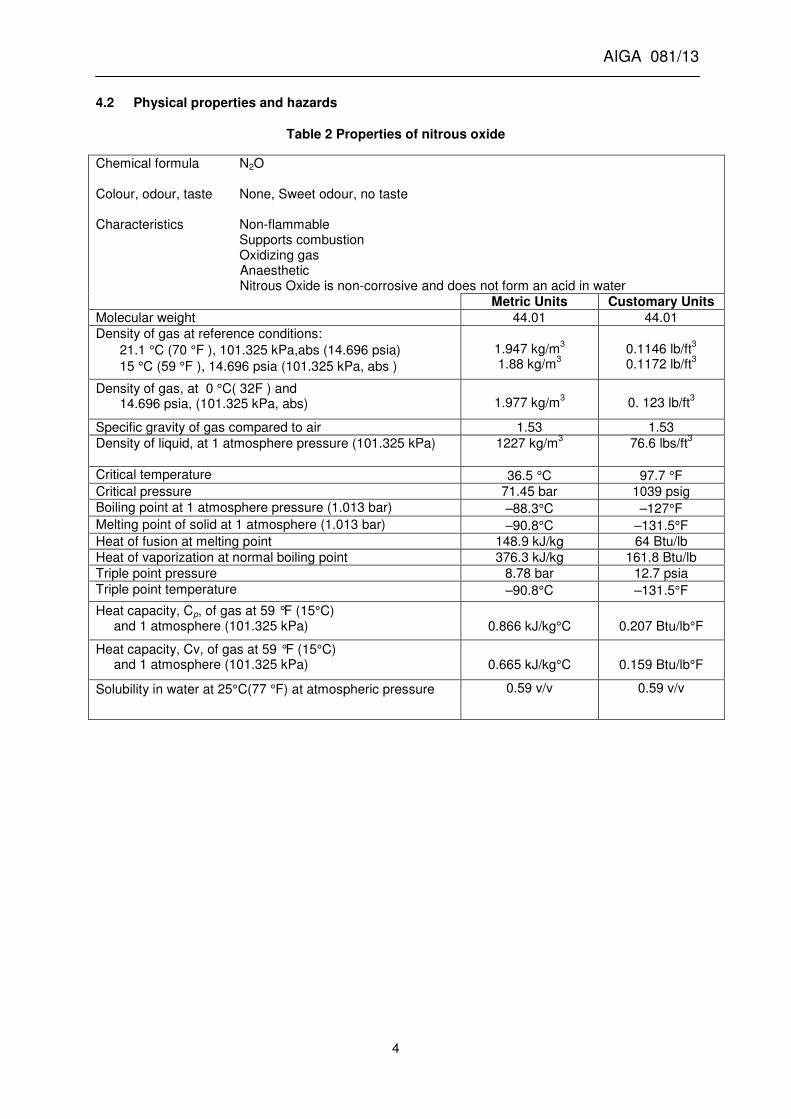
4.2 Physical properties and hazards
Table 2 Properties of nitrous oxide
Chemical formula N2O Colour, odour, taste None, Sweet odour, no taste Characteristics Non-flammable Supports combustion Oxidizing gas Anaesthetic Nitrous Oxide is non-corrosive and does not form an acid in water
Metric Units Customary Units
Molecular weight 44.01 44.01
Density of gas at reference conditions:
21.1 °C (70 °F ), 101.325 kPa,abs (14.696 psia)
15 °C (59 °F ), 14.696 psia (101.325 kPa, abs )
1.947 kg/m
3
1.88 kg/m3
0.1146 lb/ft
3
0.1172 lb/ft3
Density of gas, at 0 °C( 32F ) and 14.696 psia, (101.325 kPa, abs)
1.977 kg/m
3
0. 123 lb/ft
3
Specific gravity of gas compared to air 1.53 1.53
Density of liquid, at 1 atmosphere pressure (101.325 kPa)
1227 kg/m3 76.6 lbs/ft
3
Critical temperature 36.5 °C 97.7 °F Critical pressure 71.45 bar 1039 psig
Boiling point at 1 atmosphere pressure (1.013 bar) –88.3°C –127°F
Melting point of solid at 1 atmosphere (1.013 bar) –90.8°C –131.5°F Heat of fusion at melting point 148.9 kJ/kg 64 Btu/lb
Heat of vaporization at normal boiling point 376.3 kJ/kg 161.8 Btu/lb
Triple point pressure 8.78 bar 12.7 psia
Triple point temperature –90.8°C –131.5°F
Heat capacity, Cp, of gas at 59 °F (15°C) and 1 atmosphere (101.325 kPa)
0.866 kJ/kg°C
0.207 Btu/lb°F
Heat capacity, Cv, of gas at 59 °F (15°C) and 1 atmosphere (101.325 kPa)
0.665 kJ/kg°C
0.159 Btu/lb°F
Solubility in water at 25°C(77 °F) at atmospheric pressure 0.59 v/v 0.59 v/v

AIGA 081/13
5
Table 3 Properties of saturated liquid nitrous oxide [3,4]
Temperature
°F Temperature
°C Vapour pressure
psia Vapour pressure
bar abs Liquid density lb/gal
Liquid density kg/litre
–131.5 –90,82 12.73 0,878
–127.2 –88,47 14.69 1,013 10.20 1,2228
–110 –78,89 26 1,793 10.36 1,241
–90 –67,78 46 3,172 10.02 1,201
–70 –56,67 73.98 5,102 9.69 1,161
–50 –45,56 111.97 7,722 9.26 1,110
–30 –34,44 166.95 11,514 8.95 1,073
–10 –23,33 239.93 16,547 8.65 1,036
10 –12,22 334.9 23,097 8.18 0,980
32 0 453.7 31,290 7.54 0,904
50 10,00 589.85 40,679 6.99 0,838
59 15,00 654.24 45,120 6.83 0,818
70 21,11 759.8 52,400 6.22 0,745
97.5 36,41 1050.5 72,450 3.86 0,452
4.2.1 Specific hazards
Personnel handling nitrous oxide should be trained in the hazards associated with this product. There are several conditions in which danger to personnel and equipment can exist. The following describes these conditions and offers procedures and guidelines to prevent dangerous conditions from developing.
4.2.1.1 Low temperature effects on materials
The low temperature effect of nitrous oxide liquid and vapour on the materials in the system can
create a hazard. At ambient pressure the temperature of liquid nitrous oxide is at -88°C (-127°F) and many materials used in hose and piping systems can become brittle and fail if highly stressed. Materials used in the construction of nitrous oxide supply systems shall be compatible with nitrous oxide and the temperature and pressure conditions encountered.
Piping systems subject to operating temperatures below ambient will contract. Allowances shall be made in piping and support systems to compensate for these changes in dimensions. Copper tubing which is commonly used will shrink approximately 2.5 cm (1 in) per 30.5 m (100 ft.) for every 55.6°C
(100°F) reduction in temperature.
Upon contact with cold nitrous oxide, materials such as rubber or plastics can become brittle and are likely to break without warning.
4.2.1.2 Trapped liquid
Liquid nitrous oxide that is forced to occupy a fixed volume (such as between two closed valves or positive shutoff points) will increase in pressure as it warms and expands. As long as there is a vapour space within the volume where the liquid is trapped, the pressure will increase about 62kPa
per C (5 psi per°F). When the volume becomes liquid full, the hydrostatic pressure increases at a rate
of 10 550 kPa per°C (850 psig per°F). As the temperature continues to increase, the pressure of the trapped liquid can exceed what the piping and components can withstand. This can cause the rupture of the piping or components with possible injury or property damage; this is the reason why it is required to install a pressure relief device between positive shut off devices.
4.2.1.3 Personnel overexposure
If sufficient amounts of nitrous oxide are released into the work environment via leaks or venting, operator exposure levels can exceed occupational exposure limits (OELs) and present a potential risk

AIGA 081/13
6
to health. In addition, gaseous nitrous oxide under atmospheric conditions is 1.5 times heavier than air and therefore can be found in greater concentrations at lower levels, potentially displacing oxygen in confined spaces and causing an asphyxiation hazard. Nitrous oxide exposure levels should be controlled so that the health and safety risks to operators are minimised to acceptable levels i.e. below the relevant OELs. Nitrous oxide in the gaseous state is colourless and has a sweet odour. Ventilation systems, if required, should be designed to exhaust from the lowest level and allow make-up air to enter at a higher point.
Nitrous oxide liquid or cold vapour that comes into contact with the skin or mouth can cause freezing or frostbite. If frostbite occurs, obtain medical attention. Do not rub the area, immerse in warm water
38°C to 41°C (100°F to 105°F)
Liquefied nitrous oxide, UN 1070, is handled in cylinders at a pressure of 50 kPa (735 psi) at 21°C
(70°F). Nitrous oxide refrigerated liquid, UN 2201, is stored in insulated tanks at pressures ranging in
North America from 260-315 psi at temperatures of 0-+10°F and in Europe 20 bar to 25 bar at temperature of approximately – 20°C. Liquid nitrous oxide forms a mixture of extremely cold liquid and gas when discharged to atmospheric pressure. Skin contact with such liquid can cause severe frostbite.
4.3 Chemical properties and hazards
4.3.1 Oxidizing ability
Under the action of heat nitrous oxide decomposes into its elements irreversibly and exothermally see 4.3.2, to produce a mixture which is richer in oxygen than air.
N2O � N2 + ½ O2 + 82 kJ / mol
As by-products of nitrous oxide decomposition toxic nitrogen oxides can be formed.
After decomposition nitrous oxide becomes an oxidizing gas with an oxypotential higher than that of air. Consequently nitrous oxide is classified in standards and regulations as an oxidizing gas, see Table 4
Table 4 Nitrous oxide
Reference UN number / Shipping name
United Nations Model Regulations: Recommendations on the Transport of Dangerous Goods [2]
UN-No.1070 / Nitrous oxide UN-No.2201 / Nitrous oxide, refrigerated liquid
ISO 10156 Gas cylinders - Gases and gas mixtures – Determination of fire potential and oxidizing ability for the selection of cylinder valve outlets [5]
Oxypotential 0,6
Note: Due to the oxypotential of nitrous oxide, a fire hazard can be created if the gas comes in contact with flammable gases or combustible substances in presence of an ignition source.
4.3.1.1 Metals
No burning of metals in contact with nitrous oxide has been reported. In theory the only condition in which metals could burn is after nitrous oxide decomposition.

AIGA 081/13
7
4.3.1.2 Non-metals
Ignition of non-metals such as plastics, elastomers and clothing materials in contact with nitrous oxide is possible by the influence of heat (for example, generated by adiabatic compression) or flame.
4.3.1.3 Oil and grease
Oil and grease are unacceptable contaminants in a nitrous oxide installation and can create a severe fire hazard. Such fires can be ignited due to adiabatic compression or high temperature, see 4.3.3.
4.3.1.4 Flammable gases
Flammable gases form explosive mixtures with nitrous oxide, see Table 5. The explosion limits are influenced by the specific chemical properties of nitrous oxide:
• The lower explosion limit of flammable gases is much lower with nitrous oxide than with air or oxygen, since the heat release by decomposition of nitrous oxide supports the combustion of combustible-lean mixtures; and.
• The upper explosion limit of flammable gases is much higher with nitrous oxide than with air, since the higher oxypotential of nitrous oxide supports the combustion of combustible-rich mixtures.
Table 5 Explosion limits for some typical flammable gases with nitrous oxide at atmospheric conditions
Lower explosion limit, mole-% Upper explosion limit, mole-%
in air 1)
in oxygen 2)
in nitrous oxide
1)
in air 1)
in oxygen2)
in nitrous oxide
Methane 4,4 5,15 1,5 16,5 60,5 49,5
Propane 1,7 2,3 0,7 10,9 52,0 27,0
Hydrogen 4,1 4,0 2,9 77,0 94,0 82,5
Ammonia 15,4 15 4,4 33,6 79 65,0
NOTE—Other literature sources can provide slightly different values, but the general conclusion is that nitrous oxide is more oxidizing than air. Safety precautions in respect of flammable gases, see 5.11. 1)
Directive 96/61/EC, Integrated Pollution Prevention and Control Directive [6] 2)
Directive 2003/87/EC, Establishing a scheme for greenhouse gas emission allowance trading within the Community and amending Council Directive 96/61/EC [7]
4.3.2 Stability
Under normal operating conditions, nitrous oxide is a stable compound in both the liquid and gaseous states. Nitrous oxide is classified as a non-flammable gas, with oxidizer as a secondary classification.
Accidents and experiments have shown that nitrous oxide as a result of its positive formation energy can decompose exothermally. This decomposition reaction can be self-sustaining and violent. The theoretical pressure ratio at decomposition – final pressure / initial pressure – can reach 10 to 1 [8].
If improperly handled, nitrous oxide can decompose irreversibly, and potentially explosively, into nitrogen and oxygen:
2N2O � 2N2 + O2 + Heat
While nitrogen and oxygen are the primary products from nitrous oxide decomposition, the higher nitrogen oxides (NO/NO2) are also produced.

AIGA 081/13
8
Decomposition of nitrous oxide is a homogeneous, first order reaction. Nitrous oxide releases 1860.8 kJ per kg (800 BTU per pound) upon decomposition. Nitrous oxide decomposition progresses as a purely thermal process, whereas a propane-air flame front precedes by a combination of thermal and chain carrier processes. The propagation speed of nitrous oxide decomposition reaction is 30 times slower than the flame propagation speed for propane-air and the reaction is easily quenched. [8]
It is important for those handling nitrous oxide to understand and avoid sources of decomposition and to understand at what conditions the decomposition front will or will not propagate.
Liquid nitrous oxide is relatively insensitive to high energy sparks or external shocks. Decomposition of the liquid could not be initiated by an exploding wire in the laboratory. Limited decomposition has been induced in the liquid by blasting caps. Laboratory results indicate that nitrous oxide can be safely handled in the liquid state but decomposition hazards exist in the gaseous state at elevated pressure and/or temperature. The reaction can propagate through vapour with liquid present [8].
4.3.3 Decomposition sources
All of the following have been known to initiate nitrous oxide vapour decomposition:
Table 6 Decomposition sources
Field decomposition sources Laboratory decomposition sources
Static discharge Electric spark
Spark (Metal to metal contact) Exploding wire
Adiabatic heat of compression Glowing wire
Secondary exothermic chemical reaction Blasting cap
Welding/brazing Heat of compression
Heat generated by a dry running pump
Electric immersion heater
Internal impact
External source of heat
4.3.3.1 Temperature and pressure
Nitrous oxide decomposition will not propagate at relatively low temperatures and pressures see Figure 1. Three outcomes are possible after a decomposition ignition source has been applied to a pipe or vessel containing nitrous oxide vapour. In order of progressively higher temperature and pressure they are:
• Nothing happens;
• Decomposition is initiated, but the reaction is quenched (below the propagation threshold); and
• Decomposition is initiated and the decomposition front propagates through the pipe or vessel (above the propagation threshold).
At extreme conditions (for example 762°C at 3.5 atmosphere,) [9], nitrous oxide vapour is capable of auto-ignition without an external decomposition source.

AIGA 081/13
9
Figure 1 Propagation threshold for nitrous oxide
4.3.3.2 Vessel and pipe geometry
In order for a nitrous oxide decomposition to propagate, the heat generated by the reaction must be sufficient to heat the next element of un-reacted gas to the decomposition temperature. Heat lost to pipe walls reduces the potential for propagating the reaction. Smaller diameter lines have a higher internal surface area to volume. Therefore in smaller diameter pipes, more heat per unit volume is lost to the pipe walls and higher temperatures and pressures are required for a decomposition front to propagate see Figure 1.
4.3.3.3 Propagation threshold
The potential for an explosive decomposition to take place is more closely coupled to the quenching characteristics (temperature, pressure, container geometry) of the nitrous oxide system than with the initial decomposition energy, [9].
Figure 1 is a representation of the testing completed in ref [9].
The propagation threshold shown in Figure 1 should be considered as an approximation but can give the user some indication if they are handling nitrous oxide well above or well below the propagation threshold. When handling nitrous oxide vapour under conditions at which the reaction will propagate, care shall be exercised to avoid any possibility of a decomposition source.

AIGA 081/13
10
It is desirable to operate below the propagation threshold by controlling pressure, temperature, or line size.
4.3.3.4 Impurities
Inert Gases – Dilution of nitrous oxide vapour with a non-flammable gas such as helium or nitrogen will raise the propagation threshold. In one study, the propagation threshold of the pure vapour at 20.7
bar (300 psi) was approximately 250°C (480°F). Addition of 20v% nitrogen raised the 20.7 bar (300
psi) threshold to 465°C (870°F) in the same reactor with the same ignition source. It was not possible to obtain ignition with the addition of 46v% nitrogen. [10]
Combustible Materials – Any combustible material such as hydrocarbon lubricants or flammable mixtures will promote violent decomposition and lower the propagation threshold. A flammable mixture will lower the propagation threshold even if present below the lower explosion limit. All equipment that will be in contact with nitrous oxide shall be cleaned for oxygen service and lubricants shall be oxygen compatible.
4.3.3.5 Large pressure vessels
Most nitrous oxide decomposition incidents have occurred in large pressure vessels such as a storage tank or cargo tank. As the vapour volume and temperature increase, the risk of disassociation increases. Decomposition can be initiated by a variety of ignition sources, which are listed in 4.3.3. The decomposition can also be initiated by external heat (such as welding or brazing) on the vessel or vessel piping, or heat generated by a dry running pump. If initiated in the piping, the reaction front can travel through the piping and into the vessel if operating above the propagation threshold. Once the reaction front is inside the vessel there is effectively no heat sink to quench the reaction. Since 1.5 moles of gas are created for each mole of decomposed nitrous oxide, the decomposing nitrous oxide compresses and heats the unreacted nitrous oxide as the reaction front moves into the vessel. Eventually the unreacted nitrous oxide reaches high enough temperature and pressure to auto-initiate, resulting in an explosion.
Safety guidelines
• Do not weld, braze, or strike an arc on any pipe, cylinder, or vessel that contains nitrous oxide.
• Ball valves and other quick opening valves should be opened slowly. High temperature caused by adiabatic compression could cause nitrous oxide decomposition.
• Nitrous oxide transfer pumps shall be provided with an interlock to prevent dry running, see 7.4.
• Piping should operate below the propagation threshold when possible. See Figure 1. Use the smallest practical line size
NOTE: Experience has shown that most large diameter vessels operating above the propagation threshold, have been used safely because safeguards noted in this publication have been taken, for example, avoiding decomposition initiators)
• Clean all surfaces in direct contact with nitrous oxide as for oxygen, see 5.5.
• Oxygen compatible lubricants shall be used when potentially in contact with nitrous oxide.
• Use self-limiting heating devices, for example, direct contact electric immersion heaters are not allowed.
4.4 Occupational exposure
The health effects of nitrous oxide are discussed only with regard to operators who are involved in transport, filling and handling of nitrous oxide. The effect of nitrous oxide as medicinal product is not considered.

AIGA 081/13
11
4.4.1 Short-term exposure
Nitrous oxide in the gaseous state is colourless and has a sweet odour. Elevated concentrations of this gas in the air can be reached quickly on loss of containment for example, via leaks and venting. The short term health effect is primarily the narcotic effect which includes dizziness, nausea, headache and loss of coordination. In addition, gaseous nitrous oxide under atmospheric conditions is 1.5 times heavier than air and so can be found in greater concentrations at low levels and therefore, if allowed to displace oxygen in a confined space, can also be an asphyxiation hazard.
Nitrous oxide liquid or cold vapour coming in contact with the skin or mouth can cause freezing or frostbite. If frostbite has occurred, obtain medical attention. Do not rub the area, immerse in warm
water 38 °C to 41 °C (100°F to 105°F)
4.4.2 Long-term exposure
Nitrous oxide has been associated with several side effects from long term exposure. The most strongly substantiated effect is neuropathy. Epidemiological studies also suggest feto-toxic effects and higher incidents of spontaneous abortion in exposed personnel. Although no cause–and–effect relationship has been firmly established, exposure to the gas should be minimized. National regulations vary the 8 hour time weighted average (TWA) exposure ranges from 25ppm to 100 ppm. The American Conference of Governmental Industrial Hygienists (ACGIH) recommends limiting exposure to 50 ppm on an eight hour TWA basis [11].
4.4.3 Control of exposure to nitrous oxide gas in the workplace
Operator exposures (for example, filling operators) to nitrous oxide gas should be controlled to acceptable levels (i.e. below the relevant OELs). Sources of nitrous oxide can include:
• uncontained filling equipment allowing some nitrous to be expelled before/after filling;
• leaking equipment for example, filling equipment;
• venting empty cylinders to the open air instead of to a blow down manifold;
• valves not closed sufficiently on empty and full cylinders to ensure no leakage of product; and
• poorly positioned vents leading to re-entrainment of gas into the building
Control measures should be in place to prevent nitrous oxide leaking or being vented into the workplace. Examples include:
• venting cylinders to a dedicated manifold rig (including purging and vacuum capabilities) that is contained and vented away from the work area;
• ensuring the filling system is designed so that nitrous oxide is not released into the work environment via venting or leaking;
• vents are located outside buildings and above roof level;
• preventative maintenance programme to prevent leaks; and
• procedures, for example, ensuring empty cylinder valves are closed prior to transporting them into the filling area.
If nitrous oxide is stored or filled in insufficiently ventilated rooms a gas monitoring system should be installed in order to monitor the concentration of nitrous oxide in the room.

AIGA 081/13
12
4.5 Environmental issues
The emission of nitrous oxide from commercial production is estimated to be approximately 1% of total emissions. This is based on data from the United States Environmental Protection Agency (EPA) Nitrous Oxide Emissions by Source (million tonne CO2 Equivalents).
In some parts of the world the releases of nitrous oxide to the atmosphere are restricted by regulation.
In Europe, European Directives [6, 7] shall be applied and best available techniques need to be used to prevent and minimise nitrous oxide emissions .The Seveso III Directive [12] applies to nitrous oxide, if the quantity which is present at one time on the site exceeds the following quantities:
• Greater than 50 tonnes: A notification on the quantity of substance and a major accident prevention policy is required.
• Greater than 200 tonnes: An official safety report is required.
In the United States the Emergency Planning and Community Right to Know Act (or SARA Title III) Section 311 and 312 regulations apply to nitrous oxide, if the quantity that is present at one time on the site exceeds 10 000 pounds [13].
4.6 Security
Security measures should be implemented to restrict access to nitrous oxide to authorized personnel only. For more details refer to AIGA , Site Security [14]. Security is an issue primarily because nitrous oxide is frequently subject to inhalation abuse. This abuse can result in asphyxiation or long term exposure health effects, as described in Section 4.4.2, thereby requiring stricter methods to control access and potential abuse.
For additional security guidance concerning transportation of nitrous oxide and qualifying customers purchasing nitrous oxide see AIGA 043, Transport Security Guidance for Members, and AIGA 091, Guidance for Qualifying Customers Purchasing Compressed Gases [15, 16].
A policy for the sale of nitrous oxide shall be in place. It shall be ensured by a thorough review before the purchase is approved and the delivery is made that the customer has a valid reason to purchase nitrous oxide and that the tracking records for nitrous oxide shipments shall be maintained.
Nitrous oxide has a multitude of beneficial applications such as an anaesthetic or as a food propellant that ultimately improve the quality of people’s lives. When misused, abused, or handled improperly it can harm people, and potentially cause death.
5 Equipment and procedures
5.1 Principles
The equipment used to handle nitrous oxide shall be designed, constructed and tested in accordance with the regulatory requirements in the country in which the equipment is operated. The equipment shall be designed to withstand the maximum pressures and temperatures to which it is to be operated and also to minimise the release of nitrous oxide.
Because of the properties and hazards of nitrous oxide consideration shall be given to avoid combustible materials and any uncontrolled heat input.
General rules described apply to nitrous oxide systems where the pressure is below 71.5 bar (1051
psi)/(36,45°C (97.5°F). Above this pressure, i.e. in the supercritical state of nitrous oxide, rules defined for pure oxygen concerning material compatibility, equipment selection (for example, AIGA 089 Reciprocating Cryogenic Pumps and Pump Installations [17], when applicable) should be considered for nitrous oxide as well. The oxygen rules are also applicable to nitrous oxide / oxygen mixtures irrespective of the partial pressure or percentage of nitrous oxide is.

AIGA 081/13
13
5.2 Compatibility of materials with nitrous oxide
Due to possibility of reaction of materials with nitrous oxide and considering its oxidizing properties, metals and non-metals shall be selected as follows.
5.2.1 Metals
There is no restriction regarding the use of common commercial metallic materials for nitrous oxide installations. Primarily carbon steel, manganese steel, chrome molybdenum steel, stainless steel, brass, copper, copper alloys and aluminium are considered to be suitable for use with nitrous oxide see [3] and ISO 11114-1 Transportable gas cylinders – Compatibility of cylinder and valve materials, [18]. The only exception is that there is no safe demonstrated experience using aluminium in nitrous oxide pumping systems.
5.2.2 Non-Metals
Examples of non-metallic materials exhibiting the best compatibility with gases having a high oxypotential, see ISO 11114-2 Transportable gas cylinders – Compatibility of cylinder and valve materials [19]:
• Plastic products such as polytetrafluoroethylene (PTFE), polychlorotrifluoroethylene (PCTFE), Fluorinated Ethylene-Propylene (FEP) polyetheretherketone (PEEK
TM) and ethylene propylene
diene monomer (EPDM). Others such as polyvinylchloride (PVC), poly-vinylidenfluoride, polyamide (Nylon 66®),Vespel SP21®) and polypropylene can be used with due regard to the external fire risk.
• Certain grades of elastomers such as Viton® or Neoprene® are known to swell in pressurised nitrous oxide and non-swelling grades are preferred when swelling can be an issue
• Non-metallic materials to be used in high pressure (pressure great than 30 bar (435 psi)) nitrous oxide / oxygen mixture application shall conform to specific requirements considering toxicity risks, see AIGA 059 Design considerations to mitigate the potential risks of toxicity when using non-metallic materials in high pressure oxygen breathing systems [20]; and
• Lubricants in contact with nitrous oxide shall be compatible.
5.3 Valves
Materials for high pressure nitrous oxide valves such as cylinder valves shall be selected according to ISO 11114-1 and ISO 11114-2 [18, 19]. Commonly used metals are brass, copper alloys, carbon steel. Acceptable non-metallic materials are the plastics PTFE, PCTFE, polyamides and the elastomer silicon rubber.
Valves for refrigerated liquefied nitrous oxide shall meet the requirements regarding design, testing and marking for the intended service, see ISO 21011 Cryogenic vessels – Valves for cryogenic service [21]. Metallic and non-metallic materials for such valves shall have passed a test for oxygen compatibility such as ISO 21010, Cryogenic vessels – Gas/materials compatibility to [22]. Ball valves used for liquefied nitrous oxide are recommended to be bored or otherwise designed for pressure relief towards the tank to prevent trapping liquid inside the ball.
5.4 Filters
Filters or strainers shall be designed considering the oxidizing properties of nitrous oxide. Mesh filters or strainers made from high nickel alloys such as Monel®, Inconel®, nickel 200 alloys or high copper alloys such as brass are preferred due to increased resistance to oxidizer fires. No glue or similar combustible material shall come into contact with nitrous oxide at pressure greater than 10 bar (145 psi).

AIGA 081/13
14
Liquid nitrous oxide should be filtered as fine as possible. Hole size of the filter is a compromise between allowable pressure drop, space available and acceptable thermal mass of the filter body, see AIGA 089 [17].
Gaseous nitrous oxide should be filtered using mesh sizes between 30 and 100 corresponding approximately to a 500 to 150 micron particle size capture, see AIGA 021 Oxygen pipeline and pipeline systems [23].
5.5 Cleaning of installation
Any equipment and installation designed for nitrous oxide service shall be cleaned for oxygen service according to AIGA 012, Cleaning of equipment for oxygen service or ISO 23208 Cryogenic vessels – Cleanliness for cryogenic service [24, 25]. Where it is necessary to change the product service of equipment from any gas to nitrous oxide, same rules apply for cleaning. Pressure receptacles which are to be changed to nitrous oxide service shall be cleaned using an appropriate procedure. For cylinders see ISO 11621, Gas cylinders—Procedures for change of gas service [26] and for transport tanks see EIGA Doc 87, Conversion of Cryogenic Transport Tanks to Oxygen Service [27].
The surfaces that come into contact with nitrous oxide shall be cleaned to remove all combustible particles and oil and grease that could have been introduced into the system during its construction, fabrication or maintenance. The equipment shall be cleaned, as for oxygen service, using detergents or suitable cleaning agents that are free from non-metallic or metallic particles.
The maximum quantities of foreign matter (oil, grease, organic materials) in the installation shall not exceed 500 mg/m
2.Visible particles, fibres or drops of water shall not be accepted, see AIGA 012 [24].
5.6 Prevention of contamination
Hoses and filling connections or other pieces of equipment that are not continually connected, shall be protected against the ingress of dirt and moisture by caps and / or nuts, when not in use.
5.7 Avoiding high temperature
Temperatures above 150°C (300°F) shall be avoided by all practical means, to reduce the likelihood of an explosive decomposition of the nitrous oxide.
Electric heating devices in direct contact with nitrous oxide are prohibited. Only indirect electric heaters are allowed with sufficient safety controls to prevent exceeding 150°C (300°F) are allowed. Water bath heaters, low pressure steam, or other temperature self-limiting devices are recommended;
• All pumps, compressors, or other equipment with rotating or sliding components shall be protected by automatic controls against loss of prime and excessive operating temperatures. Pumps shall not be allowed to operate with no flow or loss of prime. A number of serious accidents have been attributed to overheated equipment.
• Best practice for liquid transfer pumps is to install the pump with a flooded suction line and a liquid return connection to help quench a decomposition reaction. Strainers should be installed on the suction and discharge of liquid pumps to provide a heat sink that assists in quenching a decomposition flame front.
• WARNING: Hot work shall not be performed on any equipment containing nitrous oxide. All equipment shall be purged with an inert gas or air prior to hot work. Be aware that thermal conduction from hot work areas can migrate to piping containing nitrous oxide and lead to an explosion or fire.
• Medical installations could require purging with medically certified gases per some local regulations during any hot work to prevent the formation of oxides.

AIGA 081/13
15
• Hot work should not be performed within 1m (3 ft.) of a section of piping that still contains nitrous oxide. Hot work close to a nitrous oxide installation can also require removal of nitrous oxide and purging, depending on the risks and type of work. Such work shall require a work permit issued in accordance with all regulatory and supplier requirements, see AIGA 011 Work permit systems [28];
• Heat from an open flame or a hot air gun shall not be applied to any part of a nitrous oxide installation for de-icing, releasing threaded couplings, or for increasing pressure in cylinders. However, hot air guns are acceptable when systems are at atmospheric pressure; use of water as a warming agent is acceptable.
• Thermal mass flow meters shall not be used due to the internal heater element, unless a risk assessment is carried out to ensure that there is no risk of thermal decomposition. One application is the use of mass flow meters to measure any emissions to atmosphere through vents.
• Nitrous oxide installations shall be grounded in accordance with local regulatory requirements, for example Directive 94/9EC, Equipment and protective systems for use in potentially explosive atmospheres (ATEX) in Europe and NFPA 70, National Electric Code in North America. before use in order to dissipate any electrostatic charges, [29, 30]
• Strainers or filters shall be located in order to avoid migration of particles within specific devices (for example, compressor, pump).
Ball valves and other quick opening valves should be opened slowly. The high temperature caused by adiabatic compression can provide an ignition source that could lead to the rapid decomposition of nitrous oxide, see 4.3.3.5.
5.8 Restriction of flow velocity
Nitrous oxide flow can cause localized heating of a material by particle impact or flow friction, particularly in areas with narrow passages. This heat can initiate a local decomposition / combustion if the decomposition temperature of the material in contact with nitrous oxide is reached. The nitrous oxide velocity should therefore be limited to avoid this temperature being achieved.
When designing or modifying an installation, a conservative guide would be to use the velocity limits which are defined for oxygen, see AIGA 021[23].
5.9 Operating procedures
As with any operation associated with a hazardous substance, written operating procedures shall be prepared. Operators shall be trained in these procedures.
Management shall ensure operators understand that the equipment has to be operated within its design parameters, so as not to cause a hazard to personnel or damage to the equipment or environment.
Included in the procedures shall be a statement to indicate that no part of the installation shall be heated higher than the normal operating temperature, Figure 1.
5.10 Maintenance procedures
Nitrous oxide equipment shall be maintained by qualified and trained personnel in a routine, controlled and safe manner following written procedures.
Modifications to a nitrous oxide installation or non-routine maintenance work shall not be made without a risk assessment which could result in a management of change and requirement for a work permit, see AIGA 011 [28]. Also see AIGA 010, Management of Change [31].

AIGA 081/13
16
Particular consideration shall be given to ensuring that the integrity of the cleanliness of the system is maintained and that spare parts and lubricants that come in contact with nitrous oxide are compatible with nitrous oxide.
Pressure equipment shall be depressurised prior to any maintenance or repair (if welding or other hot work is to be performed the system shall be purged with air or inert gas). For information on hot work see 5.7.
5.11 Isolation from flammable gases
To ensure that there is no hazard of inadvertent mixing of nitrous oxide with flammable gases or liquids, nitrous oxide equipment and pressure containers shall be dedicated to nitrous oxide service. Change of service of other equipment shall require a procedure using ISO 11621, Gas cylinders- Procedures for change of gas service [26]. Cylinders and tubes may be covered by another gas service in accordance with ISO 11621. [26].
Where nitrous oxide has to be mixed with other gases, precautions shall be taken to ensure that no flammable gas is unintentionally mixed with nitrous oxide, see AIGA 047, The safe preparation of gas mixtures [32]. Mixtures of nitrous oxide with flammable gases shall only be produced in accordance with AIGA 058, Safe Preparation of Compressed Oxidant-Fuel Gas Mixtures in Cylinders [33]
Mixing of nitrous oxide with self-igniting gases such as silane shall be prevented under all circumstances, since immediate ignition and explosion can occur. Some processes that use nitrous oxide and self-igniting gases, such as silane, in separate steps shall be protected with effective backflow preventive devices to prevent backflow of gas.
5.12 Use of carbon dioxide equipment
Carbon dioxide equipment which has similar temperature and pressure requirements to nitrous oxide, shall not be used for nitrous oxide service unless a conversion procedure has been followed for the change of service, for gas cylinders see ISO 11621 [26]. The procedure shall meet the relevant requirements of this publication or any other applicable standard or regulation. Care shall be taken with regard to design, material, insulation, cleanliness, lubricants, seals, and avoiding high temperature.
Medical installations shall follow national regulations regarding cleaning (and certifying if applicable) for proper service.
WARNING: Unlike carbon dioxide, nitrous oxide shall not be used as a pneumatic energy source to actuate pneumatic cylinders, valve actuators or as an inert gas.
6 Stationary tanks
Stationary tanks are used in nitrous oxide production plants, filling plants and customer installations. This section refers to all these types of tanks.
6.1 Design
There are two different tank types as follows:
6.1.1 Insulated tanks
Insulated tanks are used for the storage of refrigerated liquid nitrous oxide at temperatures below –20 °C (–4°F) and corresponding vapour pressure in the range of 18 bar to 25 bar (260 psi to 362 psi).
The typical maximum working pressure (MAWP) for nitrous oxide tanks ranges from 16 to 25 bar (232 to 362 psig). The normal operating conditions are 17.7 to 21.4 bar (257 to 310 psig) at corresponding temperatures of –16°C to –12°C (0°F to –10°F). The minimum design metal temperature (MDMT) shall be less or equal to the minimum normal operating temperature. Newly constructed tanks should

AIGA 081/13
17
have an MDMT of –40°C (–40°F) or colder to better handle the low temperature upset conditions caused by loss of tank pressure.
There are two types of insulated tanks:
• Vacuum insulated tanks with the inner tank typically made from stainless steel or fine grain carbon steel and the outer tank from carbon steel. Vacuum insulated tanks have the lowest external heat input to the inner tank; and are therefore less susceptible to external heating caused by fire or ambient heat that could lead to a decomposition of the nitrous oxide.
• Non-vacuum insulated tanks with the inner tank typically made of low alloy carbon steel and the outer cladding made of steel or aluminium.
Insulation material:
• The insulation system shall be non-combustible or fire resistant, for example, the material shall not continue to burn when the external flame is extinguished.
• An insulation system made of polyurethane with cladding made of steel or aluminium is considered to be fire resistant.
• If the insulation system of an existing tank has to be replaced, it should be rebuilt using a fire resistant insulation system (for example, polyurethane with cladding) or non-combustible material such as glass wool, foam glass or mineral wool. A suitable vapour barrier is required to prevent the insulation from becoming saturated with condensed moisture.
6.1.2 Non-insulated high pressure tanks
Non-insulated high pressure tanks are typically made of carbon steel, for storage of liquefied nitrous oxide at ambient temperature with corresponding vapour pressure, in the range of 45 to 60 bar, (640-900 psi), corresponding to a temperature range of 13°C to 27°C (56°F to 82°F). The high operating pressure of this tank type requires high-pressure filling pumps and sometimes the use of two pumps in series. This increases the hazard of heat production and subsequent decomposition. Furthermore in case of an external fire, the tank content can be heated up rapidly. For these reasons because of the increased potential of decomposition in such condition the use of non-insulated tanks shall be discouraged unless a risk assessment has been completed and mitigation has been provided.
6.1.3 Vessel installation
Safety requirements for all fixed tank types:
• The tank shall be installed on an engineered foundation that meets all local and national building codes.
• Support and foundation of the tanks is recommended to be non-combustible.
• Tanks should be installed outdoors. In the very rare cases where indoor installation is necessary, ventilation and access for filling shall be provided. Nitrous oxide or oxygen deficiency levels in the ambient air shall be monitored. Further information on the hazards in indoor installations is documented in e. g. ISO 21009-1 Cryogenic vessels – static vacuum insulted vessels – Part 1: Design fabrication, inspection and tests or CGA G-8.1Standard for nitrous oxide systems at consumer sites [34, 35].
• Tanks shall be located away from any potential fire situation. Local regulations concerning safety distances shall be observed AIGA 030 Storage of cryogenic air gases at user’s premises [36].

AIGA 081/13
18
• All parts of nitrous oxide tanks shall be bonded to ensure electrical continuity and grounded. The electrical potentials between the tank and the ground should be equalised during service.
• Some old nitrous oxide tanks (including old carbon dioxide tanks) were manufactured using course grain low alloy steels that have been shown to have low temperature impact properties. Because of similarities between nitrous oxide and carbon dioxide properties the recommendations in CGA PS-5 CGA Position Statement on the Suitability of Carbon Steel Containers for Stationary Carbon Dioxide Storage [37] should be considered.
6.2 Refrigeration units
A mechanical refrigeration unit is typically installed on non-vacuum insulated tanks and on some vacuum insulated tanks. The refrigeration unit is used to reduce the tank pressure by condensing vapour which prevents discharging nitrous oxide to the atmosphere. Installations that fill cylinders typically require a refrigeration unit sized to overcome the ambient heat input introduced by the filling process. See AIGA 069, Recommendations for safe filling of CO2 cylinders and bundles [38] for reference to similar carbon dioxide filling procedures. The refrigeration evaporator coil is typically installed in the tank vapour space and shall have as few joints as possible and be all welded or brazed.
WARNING: Mixing of hydrocarbon refrigerants and oils with nitrous oxide can lead to violent reaction within the refrigeration system. Therefore to avoid the risk of refrigeration coil leaks no mechanical fittings inside the tank on the refrigeration evaporator are allowed.
It is suggested that when older fluorocarbon refrigeration systems are repaired that they be converted to synthetic lubricants such as polyolester (POE) that have a higher flash point. Refrigeration compressor failure or high pressure throughout the refrigerant circuit can be an indication of a nitrous oxide evaporator coil leak and should be thoroughly investigated.
No hot work (brazing) on the refrigeration system is allowed without first emptying and purging the container of nitrous oxide and purging with an inert gas.
6.3 Vaporizers and heaters
Nitrous oxide is a liquefied gas which means that withdrawal of vapour or liquid from the tank will cause the remaining liquid to partially boil and auto-refrigerate. Continued product withdrawal will cause the pressure and temperature of the remaining liquid to decrease. The temperature of the tank shall not be allowed to decrease below the MDMT (see 6.1). Pressure building or direct to process vaporizers are generally required to provide sufficient external heat to maintain a safe operating pressure.
Vaporizer heat sources such as electric heating elements shall not be installed inside the tank because overheating can cause explosive decomposition of nitrous oxide.
A small ambient air heated pressure build-up coil can be sufficient to maintain the required pressure. In colder climates, an externally heated vaporizer could be required. Liquid is evaporated and the vapour re-introduced at the top of the stationary tank.
An external vaporizer is required in the withdrawal system at customer installations if nitrous oxide is to be used in the gaseous state.
If an external indirect heated vaporizer has to be used, then the heating shall be controlled to limit the temperature to a maximum of 150°C (300°F). Direct heating such as warm water, steam and warm air are safer and therefore recommended. Where electrical heating is used additional safeguards are required to ensure a maximum temperature limit of 150°C (300°F). Direct electric coils shall not be used.
A back pressure control valve (economizer) may be used to prevent tank from pressure increase, as sometimes the withdrawal rate is less than the boil-off rate.

AIGA 081/13
19
6.4 Piping, instrumentation, valves
The tank shall have a contents pressure gauge and liquid level/weight indicator.
The piping and instrumentation shall enable the following functions:
• Filling of liquid into the bottom of the tank is recommended. This would allow a potential decomposition starting at the pump to be quenched in the liquid phase.
• Product withdrawal should be by bottom line or via dip tube or through a vapour line if used to maintain tank pressure.
• Gas return to / from the top to accommodate two hose filling procedure with pressure compensation between stationary tank and transport tank.
WARNING: If there is any known risk of back contamination for example, by impurities coming from customer tanks this method can only be used if mitigating measures have been taken.
• Level indicator (for example, scale, load cell or differential pressure gauge). The admissible filling weight shall be marked. A dip tube intended to prevent a liquid full condition is an acceptable practice in lieu of marking the maximum filling weight. Typical liquid level indicators operate by measuring the differential pressure between the top and bottom of the container. In low ambient temperature conditions such gauges can require heat tracing to prevent recondensing of the vapour in the sensing lines. Any heat tracing shall use inherently safe methods to prevent temperatures from exceeding 150 °C (300 °F).
• Pressure gauge to monitor the tank pressure. It can be combined with an alarm function for high and low pressure.
• Maximum liquid level check by gas return line or full try cock depending upon tank design.
• Precautions against overpressure as a result of overfilling. Procedures and / or equipment shall be installed after a risk assessment has been performed, see AIGA 054 Prevention of Excessive Pressure During Filling of Cryogenic Vessels [39].
The diameter of process piping should be kept to a minimum to reduce the decomposition propagation threshold subject to operating constraints (see 4.3.2).
An example of a piping and instrumentation diagram (P&ID) of a stationary nitrous oxide tank is provided in Figure 2. The piping and instrumentation of nitrous oxide tanks may be different, depending on company standard and user’s demands.

AIGA 081/13
20
Figure 2 P & I diagram of a typical nitrous oxide vacuum insulated stationary tank
6.5 Pressure relief valves
Each stationary nitrous oxide bulk tank shall have two active safety relief devices sized and designed to meet all local and national regulations. Typically there are two active spring loaded relief valves or one active spring loaded relief valve plus a pressure control valve. They shall conform to regulations and standards for example, EIGA Doc 24, Vacuum insulated cryogenic tank storage systems pressure protection devices [40] and ISO 21013-1 Cryogenic vessels – Pressure relief accessories for cryogenic service. Part 1: Reclosable pressure relief valves [41].
It is recommended that a 3-way selector valve, sized for the tank operating conditions be provided for the safety relief device(s) to allow servicing and maintenance of the device without requiring the depressurization of the container.
Rupture discs are not usually recommended for use in nitrous oxide tank service because they will not re-seat after the tank pressure has decreased and it will cause the remaining liquid to boil violently and auto-refrigerate to -88 °C (-127 °F). This situation could be critical if the inner vessel is made of carbon steel which would require specific repressurization procedures that have been risk evaluated by a knowledgeable nitrous oxide technician.
6.6 Admissible filling degree / filling ratio
The admissible filling degree or filling ratio shall be verified for each stationary nitrous oxide tank.
Insulated tanks should be filled to a level that prevents them from reaching a liquid full condition before the vapour pressure reaches the pressure relief device setting. When liquid nitrous oxide is stored in a tank and there is no product withdrawal, heat leak causes the temperature and pressure to rise and the liquid to expand. If the tank becomes liquid full, the hydrostatic pressure rise can cause its catastrophic failure.

AIGA 081/13
21
The safe filling degree depends on the temperature of the liquid being transferred into the tank and on the pressure at which the pressure relief device is set to open. The colder the liquid, the more vapour space is required for liquid expansion. According to some national regulations and practical experiences the filling degree of insulated tanks shall not exceed 95 %.
The maximum filling level can be easily controlled by the gas return line or full try cock depending upon tank design.
Non-insulated tanks can be filled to the same maximum filling ratio as applied to cylinders and bundles see 7.1.
6.7 Filling of stationary low pressure tanks
When stationary tanks are filled by a pump, for safety reasons the two-hose procedure should be applied in order to minimize pressure After the distribution supply system has been evaluated and has been determined that there is no possibility of back contamination from the gas phase to the transport tank filling should be made through the bottom fill line. Tanks should not be filled by pump through the top equalizing line or any other line to the top. If filling is performed by pressure difference only without the use of a pump, the tank may be filled through the top line.
The differential pressure between the transport tank and the stationary tank shall be maintained at a level normally not exceeding 3 bar (43 psi) difference to ensure a smooth pump operation and to prevent creating any hot spots. Pump discharge pressure or flow shall be monitored to ensure that the pump is operated within the performance conditions. The pressure and the level indicator of the stationary tank shall be monitored to avoid overfilling. The full try cock or vapour return shall be opened at the end of filling to verify that the tank is not overfilled.
6.8 Product return
If the tank needs to be emptied for example, for maintenance, it could be necessary to return the product to the supplier.
This can only be performed under supervision of a qualified operator, observing specific procedure. Precautions shall be taken to avoid temperatures lower than the design temperature of the tank (see 6.1). Truck pumps should not be used for emptying stationary tanks. If no suitable pump is available, pressure transfer shall be used.
7 Supply equipment
7.1 Cylinders
It is recommended to dedicate a stock of cylinders to nitrous oxide service. Any change of service to or from nitrous oxide shall be made in accordance with ISO 11114-1, ISO 11114-2, and ISO 11621 [18,19, 26].
Suitable materials for nitrous oxide cylinders are carbon steel, chrome molybdenum steel, aluminium alloys, and stainless steel, see [18]. Cylinders made of non-metallic materials for example, full composite (type 4), shall not be used.
Valve outlet connections shall be in accordance with national standards, where available and applicable, to avoid mix up of connections. The design and testing of valves shall follow the standards and valve materials shall meet the requirements in, ISO 11114-1 and ISO 11114-2 [18, 19].
Dip tubes made of non-metallic materials shall not be used because of the risk of static electricity build up. Where metallic dip tubes are used electrical continuity shall be ensured for all parts of the cylinder and its accessories. Ensure there is no risk of separation of the dip tube from the valve during service. For these purposes it is recommended no later than the first retest to weld or to solder the connection between the dip tube and the cylinder valve. The valve shall be mounted such that electrical continuity is guaranteed.

AIGA 081/13
22
Cylinders should be filled by weight to ensure accurate fill level. To avoid accidental overpressure in the cylinder by overfilling, some regional regulations require valves be fitted with a bursting disk; where this is not the case the use of bursting disk is recommended. The set pressure of the bursting disk is established by local regulations (for example, less or equal to than test pressure in North America) but shall not exceed, including all tolerances, 1,15 times the test pressure of the gas cylinder. Under no circumstances shall disks with fusible metal backing devices be used because they do not protect against cylinder overfilling.
7.2 Bundles
In Europe where bundles are used for transporting and storing nitrous oxide the individual cylinders in the bundle are usually manifolded together and terminate with one connection point for filling and discharge. Bundles are fitted with a main isolation valve. It is recommended that isolation valves are not fitted on each individual cylinder in a bundle to avoid overfilling of individual cylinders.
In North America regulations require each cylinder to have a relief device.
Where the cylinders are equipped with individual valves each cylinder shall be filled individually.
Where non-closable fittings are used on each cylinder in the bundle only one bursting disc may be used to protect the bundle. If cylinders are equipped with individual valves, these valves and the main valve shall be equipped with a bursting disk.
The bundle shall be designed, manufactured and tested according to any applicable regulatory requirements and where appropriate a design code, for example ISO 10961 Gas cylinders. Cylinder bundles – Design, construction and testing [42].
Each individual cylinder shall be in accordance with 7.1. Pipes of metallic materials should be used for the manifold. Connections within the manifold should preferably be welded or soldered.
7.3 Transport tanks
Insulated transport tanks are used for the transport of nitrous oxide refrigerated liquid. They shall fulfil the requirements of local transport regulations. For example see European Agreement on the Carriage of Dangerous Goods or 49 CFR and Transportation of Dangerous Goods Regulations for North America [43, 44, 45].
Requirements to build such transport tanks are specified for vacuum -insulated transport tanks, for example, ISO 20421, Cryogenic vessels—Large transportable vacuum-insulated vessels, Parts 1-2 and for non-vacuum-insulated transport tanks in EN 14398, Cryogenic vessels—Large transportable non-vacuum insulated vessels—Fundamental requirements, Parts 1-3 [46, 47]. Refer to the applicable, European, North American requirements, and the International Maritime Dangerous Goods Code (IMDG) for international shipments by sea [48].
This section applies also for cryogenic liquid cylinders up to 450 litres. See EN 1251-2, Cryogenic vessels – Transportable vacuum insulated vessels of not more than 1000 litres volume – Design, fabrication, inspection and testing or ISO 21029-2, Cryogenic vessels – Transportable vacuum insulated vessels of not more than 1000 litres volume – Part 2: Operational requirements [49, 50].
7.3.1 Insulation
Vacuum insulated transport tanks are acceptable for use.
If non-vacuum insulated transport tanks are used, the insulation should be “fire resistant” (see 6.1). Where there are connections that could leak, for example, manhole-flange, pipe flanges, screwed pipe, they shall be separated from any non-fire resistant insulation material. The insulation material shall be completely covered by a protective metal cladding.

AIGA 081/13
23
7.3.2 Material
Suitable materials are aluminium, fine grain carbon steel and stainless steel for the tank including the baffles and accessories. Transport tanks manufactured after 1975 shall have a MDMT of –40 °C (-40 °F) or lower and are commonly designed for a maximum working pressure of 24 bar (348 psi).
Material that will come in contact with the transported product should be approved for nitrous oxide. If no data are available on nitrous oxide compatibility, oxygen compatibility rules should be applied, for example, according to ISO 21010, [22].
7.3.3 Piping and instrumentation
Pipes, valves, flanges, couplings etc. shall be metallic. Seal and gasket materials shall be selected according to 5.2.
The piping and instrumentation shall enable the following functions:
• Filling of liquid into the bottom of the transport tank. This would allow a potential decomposition reaction starting at the pump to be quenched in the liquid phase.
• Product discharge through bottom line;
• Gas return to / from the top for two hose filling procedure with pressure compensation between transport and stationary tank. A spray line in the top shall only be used during the initial cooling of a warm tank with product transfer from differential pressure (without the use of a pump);
• At least one “full try cock” or vapour return line in order to check the filling level limit;
• Level indicator to monitor the tank contents as an option;
• Pressure gauge to monitor the tank pressure;
• Pressure gauge to monitor the pump discharge pressure as an option; and.
• Connections to allow sampling of liquid phase and as an option gas phase.
7.3.4 Grounding
All parts of the transport tank shall be bonded to ensure electrical continuity. This can be achieved by either a ground cable or a conductive hose.
7.4 Pumps
For transfer of refrigerated liquid nitrous oxide the following pump types are currently used:
• Gear pumps;
• Sliding vane pumps; and
• Centrifugal pumps.
Any pump should have at least a nominal pressure that is equal to the maximum allowable working pressure of the tank. The pump discharge pressure should be in the range of 5 bar (72 psi).
The requirements for liquid oxygen pumps should be considered, see AIGA 055 Installation guide for stationary, electrical-motor driven, centrifugal liquid oxygen pumps and ISO 24490 Cryogenic vessels – Pumps for cryogenic service [51, 52].

AIGA 081/13
24
In addition the design of the pump has to take into account ways of avoiding sources of heat or sparks that can lead to an ignition and / or decomposition of nitrous oxide:
• Bearings that are lubricated by nitrous oxide should be avoided. Bearings that are running outside the product containing part of the pump are preferred;
• The consequences of failures and consumption of wearing parts shall be considered. The periods of maintenance shall be taken into consideration;
• The clearances between moving and stationary parts within the pump shall be as large as practical, consistent with hydraulic performance and sealing;
• Fastenings of construction elements shall be secured to prevent them loosening during service;
• Mechanical seals are recommended; and
• Material combinations of moving and stationary parts shall be selected to ensure that there is a low probability of ignition and spark production.
7.4.1 Installation
The pump shall be installed at the lowest point of the line so that the pressure drop on the suction side is as small as possible in order to meet the required net positive suction head (NPSH):
• The suction line should be as short as possible and its diameter should be equal or greater than the diameter of the pump’s suction inlet. The suction pipe shall be designed according to pump manufacturer’s instruction assuring a sufficient NPSH.
• The suction pipe shall have as few bends as possible;
• The suction line shall be fitted with a filter that shall have as little pressure drop as possible;
• Valves in the suction line should be capable of providing a full flow passage, for example, ball valves;
• An emergency shut off valve should be installed in the suction line;
• The external forces on the pump should be minimised, for example, by using flexible pipes within the suction and discharge lines; and
• The pump should be separated from the pump motor.
All parts of the pump shall be bonded to ensure electrical continuity.
7.4.2 Lubrication
Pump lubricants that can come in contact with nitrous oxide shall be oxygen compatible, see AIGA 055, Installation Guide for Stationary, Electric-Motor-Driven, Centrifugal Liquid Oxygen Pumps or ISO 24490, Cryogenic vessels—Pumps for cryogenic service [51,52].
7.4.3 Dry running protection
The primary hazard during pump operation is dry running, which leads to heating and damage of the pump. Nitrous oxide can over heat and cause a decomposition reaction, which can lead to an explosion. Dry running is most often experienced at start-up of the pump and when loss of prime occurs during operation.
Provide an interlock system that allows the pump to start only after it has been properly cooled down and filled with liquid product which protects the pump from dry running. Depending on the type of

AIGA 081/13
25
pump and usage, the system may be activated by differential pressure, temperature control, motor current and/or a suitable mass flow measuring device.
7.5 Hoses, accessories and couplings (fill connections)
Hoses are used for the transfer of liquefied nitrous oxide at ambient temperature or refrigerated liquid nitrous oxide at low temperature.
Hoses shall be designed, manufactured, and tested to withstand the temperature and pressure for the intended service, see ISO 21012, Cryogenic vessels - Hoses [53]. Suitable materials of construction for hoses and other accessories (valves, pressure relief valves, flanges, pipes) are carbon steel, stainless steel and copper alloys. If other materials are used, for example, for seals etc. the oxygen compatibility shall be considered, see for example, ISO 111140-1, [20] (ambient temperature service) or ISO 21010 [22], (low temperature service).
Transfer hoses shall be protected against the ingress of dirt and moisture by caps and / or nuts, when not in use.
Hose couplings shall meet standardized basic requirements such as “leak tightness “or “application by hand tools in a controlled manner“, see EN 13371, Cryogenic vessels – Couplings for cryogenic service [54]. The couplings should be designed to avoid confusion between different gases. Bolted flange couplings only partly meet the requirements. Both in Europe and United States dedicated couplings have been adopted. (EIGA 909, EIGA cryogenic gases couplings for tanker filling [55] or CGA V-6, Standard Bulk Refrigerated Liquid Transfer Connections [56] for tanker filling. The EIGA coupling is not intended to be used for filling customer tanks.
The coupling for the liquid filling line shall be different from the coupling for the gas return line in order to avoid confusion between liquid and gas.
All hoses, accessories and couplings shall be constructed so that electrical continuity is ensured.
The fill and product discharge connections of small transportable cryogenic containers should be permanently attached to the container by welding, brazing, or a mechanical locking device (medical), or wire ties (industrial) as required by regional regulations.
Hoses shall be inspected and maintained at frequencies defined per national requirement as a minimum and the unloader should visually inspect the hose prior to each product transfer. See CGA P-27 Recommended Hose Management Practice for Uninsulated Stainless Steel Cryogenic Cargo Tank Hose for hose requalification [57].
8 Product transfer
8.1 Cylinders and bundles
Cylinder / bundle filling stations shall be designed and built to withstand the pressure loads and the external loads during service to allow safe filling.
Nitrous oxide cylinder / bundle filling stations consist of the following main elements:
• Vacuum- or non-vacuum insulated stationary tank, working pressure approximately 20 bar (290 psi) or non- insulated high-pressure tank, working pressure around 80 bar (1160 psi);
• Reciprocating pump, working pressure up to 100 bar (1450 psi). The pump should be equipped with protection against dry running, for example, by means of a thermocouple to monitor the temperature on the discharge side. Only oxygen compatible lubrication, where the lubricant could be in contact with nitrous oxide shall be used;
• A pump by-pass if the pump is running continuously;
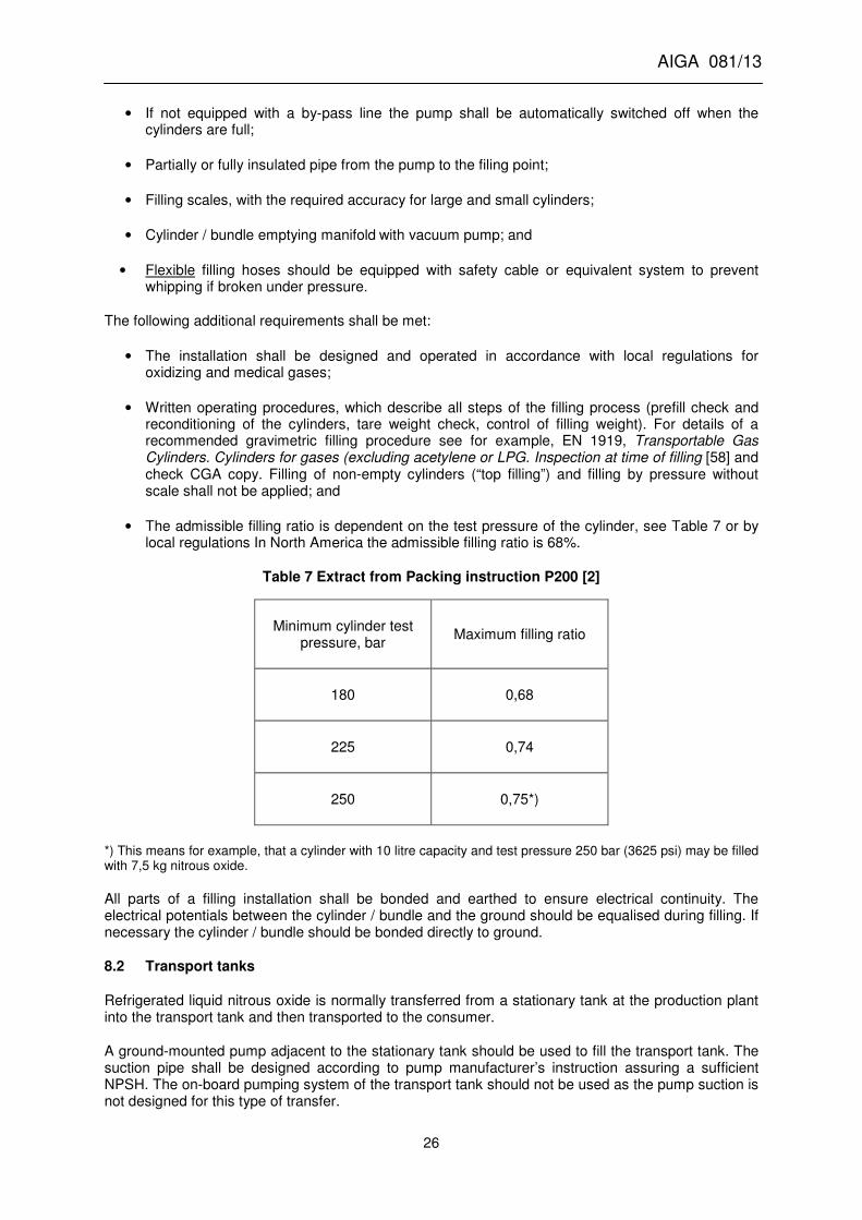
AIGA 081/13
26
• If not equipped with a by-pass line the pump shall be automatically switched off when the cylinders are full;
• Partially or fully insulated pipe from the pump to the filing point;
• Filling scales, with the required accuracy for large and small cylinders;
• Cylinder / bundle emptying manifold with vacuum pump; and
• Flexible filling hoses should be equipped with safety cable or equivalent system to prevent whipping if broken under pressure.
The following additional requirements shall be met:
• The installation shall be designed and operated in accordance with local regulations for oxidizing and medical gases;
• Written operating procedures, which describe all steps of the filling process (prefill check and reconditioning of the cylinders, tare weight check, control of filling weight). For details of a recommended gravimetric filling procedure see for example, EN 1919, Transportable Gas Cylinders. Cylinders for gases (excluding acetylene or LPG. Inspection at time of filling [58] and check CGA copy. Filling of non-empty cylinders (“top filling”) and filling by pressure without scale shall not be applied; and
• The admissible filling ratio is dependent on the test pressure of the cylinder, see Table 7 or by local regulations In North America the admissible filling ratio is 68%.
Table 7 Extract from Packing instruction P200 [2]
Minimum cylinder test pressure, bar
Maximum filling ratio
180 0,68
225 0,74
250 0,75*)
*) This means for example, that a cylinder with 10 litre capacity and test pressure 250 bar (3625 psi) may be filled with 7,5 kg nitrous oxide.
All parts of a filling installation shall be bonded and earthed to ensure electrical continuity. The electrical potentials between the cylinder / bundle and the ground should be equalised during filling. If necessary the cylinder / bundle should be bonded directly to ground.
8.2 Transport tanks
Refrigerated liquid nitrous oxide is normally transferred from a stationary tank at the production plant into the transport tank and then transported to the consumer.
A ground-mounted pump adjacent to the stationary tank should be used to fill the transport tank. The suction pipe shall be designed according to pump manufacturer’s instruction assuring a sufficient NPSH. The on-board pumping system of the transport tank should not be used as the pump suction is not designed for this type of transfer.

AIGA 081/13
27
In addition, the transport tank filling area shall meet the following requirements:
• the filling connection area should be covered with non-combustible material (such as concrete or natural stones). Wood is not acceptable;
• transport tanks should be equipotential bonded to the stationary tank during product transfer; and
• connections, seals and transfer hoses shall be kept clean by using caps, plugs etc.
Transport tanks should be filled by the two-hose filling procedure in order to minimize pressure differential and the hazard of decomposition. Filling shall be made through the bottom fill line and the gas phase shall be directed back to the stationary tank. Filling through the top equalizing line or any other line to the top is not recommended in order to avoid heat input into the gas phase by a hot running pump.
During filling the pump discharge pressure shall be monitored to ensure that the pump operates within the specified performance conditions. The pressure and the level indicator (if any) of the transport tank shall be monitored to avoid overfilling and at completion of filling the “full try-cock” shall be opened to verify that the filling quantity is correct. If designed for the function the vapour return may serve as the full try-cock.
Further operational requirements are laid down for vacuum insulated transport tanks in ISO 21029-2 [50] and for non-vacuum insulated transport tanks in EN 14398/1-3 [47], European Agreement on the Carriage of Dangerous Goods, ADR) [43]and 49 CFR 178.331 [44].
The principles of safe filling of transport tanks can also be applied for cryogenic receptacles.
8.2.1 Filling degree
The filling degree shall comply with the local regulations. In absence of local regulations the maximum filling degree shall be 95%.
Figure 3 indicates the pressure effect of overfilling a tank caused by the expansion of liquid.
Figure 3 Safe filling volumes for 22 bar nitrous oxide storage tanks

AIGA 081/13
28
9 Emergency response
9.1 Hazards
Regarding the hazards associated with nitrous oxide see Section 4. Hazards of nitrous oxide and other chemicals involved in the production of nitrous oxide are also described in the safety data sheets.
9.2 Procedures for large leaks or spills of nitrous oxide
Isolate the leak without putting oneself at risk. If possible, orientate leaking containers such that the gas escapes rather than the liquid.
In the absence of regulatory or dispersion model guidelines, isolate the area affected by the spill or leak for at least 25 to 50 metres (75 ft. to 150 ft.) in all directions. Keep unauthorized persons away and stay upwind. . A large spill (for example, unrestricted open pipe flow) may require a greater distance due to the increased volume of the discharge).
Reasonable measures shall be taken .to prevent the leaking gas / liquid from reaching low lying areas and try to prevent entry into drains, sewers, basements or confined spaces.
Ventilate and check confined spaces and rooms before entering. The check shall be conducted by competent personnel who are trained to detect potential atmospheric hazards.
Entry into a confined space demands the utmost caution. Where regulatory requirements exist they shall be followed.
Emergency responders shall avoid water contact with the pressure relief valves to avoid freezing the pressure relief valves closed.
Do not touch or walk through spilled liquid.
Try to prevent contact of cold nitrous oxide (liquid or gas) with materials, which are sensitive to cold, such as rubber or plastics.
Never use any absorbents, especially sawdust or other absorbent materials on liquid nitrous oxide spills.
9.3 Procedures at fire situations
Plant personnel should be restricted to fight only minor fires if trained and equipped for such occurrences. Professional fire fighters are trained to deal with large fires. Evacuation of plant is recommended if there is a fire in the nitrous oxide area.
9.3.1 Fires involving combustible materials with nitrous oxide
Nitrous oxide can strongly support the combustion of materials such as wood, paper, oil, clothing, etc.
In dealing with any fire situation these materials shall be kept at a safe distance from the fire.
Materials burning in nitrous oxide can produce irritating and toxic gases. Emergency responders should use respiratory protection while extinguishing fires.
Use a suitable extinguishing agent for the type of fire in question such as dry chemical, carbon dioxide or water spray.

AIGA 081/13
29
9.3.2 Fire in the area of nitrous oxide tanks
Tanks and pressure receptacles that are exposed to fire or extreme heat can rupture due to increase of temperature and pressure. In addition, nitrous oxide tanks and pressure receptacles can be subject to explosive decomposition. This can occur in spite of pressure relief equipment. Fragments of metal will be ejected through the air.
Transport tanks and pressure receptacles should be removed from the immediate fire area, if this can be achieved without risk to personnel. If this is not possible, the concerned equipment should be immediately cooled with water jets directed from a safe position, e. g. from behind heavy machinery or solid wall. Avoid water contact with pressure relief valves to avoid freezing the pressure relief valves closed.
If fire involves any tanks or pressure receptacles it shall be fought from a safe position or by using unmanned water monitors. Water-cooling of the equipment should be continued after the fire has been extinguished. Retreat immediately if the pressure relief equipment emits a hissing sound or discoloration of the tank or pressure receptacle is observed. Consider initial evacuation around an 800 metre (2400 ft.) perimeter. As an example see Emergency Response Guidebook [4].
In the event of a fire in the area containing cylinders or bundles of nitrous oxide, then the recommendations in AIGA 004 Handling of gas container emergencies [59] should be followed.
9.4 Procedures at traffic incident involving a transport tank
The actions required in the event of incidents involving nitrous oxide transport tanks depend on the circumstances.
The following is given as guidance only regarding the type of action that could be required from drivers.
Where practicable, company guidance should be obtained before any major action is taken and co-operation with the police and other emergency services shall be given at all times.
9.4.1 In the event of breakdown
• If a stop is required on the roadside due to a breakdown, look for a parking area as far away as possible from built up areas;
• Stop the engine and switch on hazard warning lights. Place warning signs on the road;
• If the position of the vehicle is likely to cause a serious traffic hazard or obstruction, notify the police or traffic authorities; and
• Report to the company for instructions regarding further actions required, such as arrangements for assistance with repairs, changes of tractor, transferring the product from the transport tank to another vehicle.
9.4.2 In the event of an incident
• If involved in an incident, stay calm, give first aid if possible;
• Stop the engine. Avoid open flames. Do not smoke. Switch on hazard warning lights and position warning signs in the road;
• Put on your high visibility clothing;
• Notify the police and, if necessary other emergency services, such as fire or medical;
• Keep bystanders at a distance and report to the company; and

AIGA 081/13
30
• Frequently check transport tank pressure and, if necessary, vent nitrous oxide gas to the atmosphere in order to reduce the pressure below the maximum allowable pressure. Find a safe place for venting and take precautions to prevent fire hazards.
9.4.3 In the event of leak or spill
• In the event of minor leaks, whenever possible, and if no hazards are involved, check and close any valves to isolate the point of leakage;
• If there seems to be no damage to the nitrous oxide tank or pipework that could develop into more serious failures, report to the company and, unless instructed otherwise, drive transport tank to the nearest company premises. Check tank pressure regularly during the journey;
• If leakage appears to be increasing, stop in a suitable place away from built-up areas, and proceed as detailed below for major leaks;
• In the event of major leaks where a release can come in contact with the tractor engine, pull to the side of the road and immediately shutoff the engine and exit the vehicle keeping all personnel away until the emergency services arrive; and
• Notify the police and report the situation to the company. Inform emergency service about the nature of the leak. Stay in attendance throughout any discharge of nitrous oxide. Warn others of danger, ensure no one in the vicinity is working in cellars, basements or trenches and consider initial downwind evacuation for at least 500 metres.
9.4.4 In the event of transport tank overturning
• If a transport tank overturns, or is lying on its side, the gas and liquid valves can be reversed, so that the liquid nitrous oxide discharges from the gas valve and vice versa; and
• Depending on the position of the transport tank in the overturned position, it may not be possible to vent gas from either the liquid valve or the gas valve.
9.4.5 In the event of fire
• If the transport tank is involved in a fire, notify the police and emergency service and report the situation to the company;
• The company should assist the fire brigade by providing information about the hazards and properties of nitrous oxide; and
• Be aware of explosive decomposition hazards
9.5 Personal protective equipment (PPE)
The following PPE is recommended for the emergency services:
• Fire fighters protective clothing is only required for fire situations; it is not effective in spill situations.
• Use self-contained breathing apparatus or supplied air respiratory protection while extinguishing fires, as fire in the presence of nitrous oxide can generate asphyxiating, irritating and/or toxic gases;
• In the event of minor leakage, wear head protection, safety goggles, gloves and safety shoes. Ensure that the area is ventilated to reduce the concentration of nitrous oxide.

AIGA 081/13
31
• In the event of major leakage, wear thermal protective clothing, face shields, cryogenic gloves, safety shoes and self-contained breathing apparatus or supplied air respiratory protection.
Requirements for the driver: Wear protective gloves, warning vest, safety goggles or face shield.
Additional guidance can be found in publication AIGA 066 Selection of Personal Protective Equipment [60].
9.6 First aid
9.6.1 In the event of inhalation of nitrous oxide:
Move the victim to fresh air, call the emergency medical services. Apply artificial respiration if the victim is not breathing; administer oxygen if difficulty is experienced with breathing.
9.6.2 In the event of contact with liquid nitrous oxide
Remove and isolate contaminated clothing and shoes. Clothing frozen to the skin should be thawed before being removed. Thaw the frosted parts with lukewarm water. Spray with water for at least 15 minutes, apply a sterile dressing, keep victim warm and calm and obtain medical assistance.
Ensure that medical personnel are aware of the product involved and take precautions to protect themselves.
9.6.3 Ingestion of nitrous oxide
Ingestion is not considered a potential route of exposure.
10 References
Unless otherwise specified the latest edition shall apply.
[1] AIGA 080 Safe Practices for the Production of Nitrous Oxide from Ammonium Nitrate www.asiaiga.org
[2] United Nations Model Regulations: Recommendations on the Transport of Dangerous Goods www.unece.org
[3] Gas Encyclopaedia - Air Liquide, www.airliquide.com
[4] Emergency Response Guidebook United States Department of Transportation http://www.phmsa.dot.gov/
[5] ISO 10156 Gas cylinders - Gases and gas mixtures – Determination of fire potential and
oxidizing ability www.iso.org
[6] European Union Directive 96/61/EC Integrated Pollution Prevention and Control Directive, www.europa.eu
[7] European Union Directive 2003/87/EC Establishing a scheme for greenhouse gas emission allowance trading within the Community and amending Council Directive 96/61/EC www.europa.eu
[8] Lewis, G.D.: Explosion and fire in nitrous oxide tank. Pratt & Whitney Aircraft Corporation Palm Beach, 1973 Pratt & Whitney Aircraft Division www.pw.utc.com.
[9] Investigation of decomposition characteristics of gaseous and liquid nitrous oxide – AFW Laboratory – Kirtland Air Force Base – New Mexico – July 1974
[10] Krisjansons, J.O.: „Explosion limit studies of nitrous oxide...“ Ohio State University, Columbus,
Ohio, 1962.

AIGA 081/13
32
[11] TLVs and BEIs Threshold limit values for chemical substances and physical agents and biological exposure indices. The American Conference of Governmental Industrial Hygienists (ACGIH) www.achih.org
[12] European Union Directive 2012/18/EU of The European Parliament and of The Council of 4 July 2012 on the control of major-accident hazards involving dangerous substances www.europa.eu
[13] Emergency Planning and Community Right-to-Know Act of 1986 (EPCRA),Superfund Amendments and Reauthorization Act (SARA), U.S. Environmental Protection Agency, Ariel Rios Building, 1200 Pennsylvania Ave., NW, Washington, DC 20460. www.epa.gov
[14] AIGA 003, Site Security Guidelines www.asiaiga.org
[15] EIGA Doc 913 Transport Security Guidance www.eiga.eu
[16] AIGA 091, Guidance for Qualifying Customers Purchasing Compressed Gases www.asiaiga.org
[17] AIGA 048, Reciprocating Cryogenic Pumps & Pump Installation www.asiaiga.org
[18] ISO 11114-1 Transportable gas cylinders – Compatibility of cylinder and valve materials www.iso.org
[19] ISO 11114-2 Transportable gas cylinders – Compatibility of cylinder and valve materials with gas contents – Non-metallic materials www.iso.org
[20] AIGA 059, Design Considerations to Mitigate the Potential Risks of Toxicity when Using Non-Metallic Materials in High Pressure Oxygen Breathing Systems www.asiaiga.org
[21] ISO 21011 Cryogenic vessels – Valves for cryogenic service www.iso.org
[22] ISO 21010 Cryogenic vessels – Gas / materials compatibility www.iso.org
[23] AIGA 021, Oxygen Pipeline and Pipeline Systems www.asiaiga.org .
[24] AIGA 012, Cleaning of Equipment for Oxygen Service www.asiaiga.org
[25] ISO 23208 Cryogenic vessels – Cleanliness for cryogenic service www.iso.org
[26] ISO 11621 Gas cylinders - Procedures for change of gas service www.iso.org
[27] EIGA Doc. 87 Conversion of Cryogenic Transport Tanks to Oxygen Service www.eiga.eu
[28] AIGA 011, Work Permit Systems www.asiaiga.org
[29] Directive 94/9EC, Equipment and protective systems for use in potentially explosive atmospheres (ATEX) www.ec.europa.eu
[30] NFPA 70, National Electric Code www.nfpa.org
[31] AIGA 010, Management of Change www.asiaiga.org
[32] AIGA 047, The Safe Preparation of Gas Mixtures www.asiaiga.org
[33] AIGA 058, Safe Preparation of Compressed Oxidant-Fuel Gas Mixtures in Cylinders www.asiaiga.org
[34] ISO 21009-1 Cryogenic vessels – static vacuum insulted vessels – Part 1: Design fabrication, inspection and tests www.iso.org
[35] CGA G-8.1 Standard for nitrous oxide systems at consumer sites www.cganet.org
[36] AIGA 030, Storage of Cryogenic Air Gases at User’s Premises www.asiaiga.org
[37] CGA PS-15 CGA Position statement on the suitability of carbon steel containers for stationary carbon dioxide storage www.cganet.org
[38] AIGA 069, Recommendations for Safe Filling of CO2 Cylinders and Bundles www.asiaiga.org
[39] AIGA 054, Prevention of Excessive Pressure during Filling of Cryogenic Vessels www.asiaiga.org

AIGA 081/13
33
[40] EIGA Doc. 24 Vacuum Insulated Cryogenic Storage Tank Systems Pressure Protection Devices www.eiga.eu
[41] ISO 21013-1 Cryogenic vessels – Pressure relief accessories for cryogenic service. Part 1: Reclosing pressure relief valves www.iso.org
[42] ISO 10961 Gas cylinders. Cylinder bundles – Design, construction and testing www.iso.org
[43] European Agreement Concerning the Carriage of Dangerous Goods www.unece.org
[44] Code of Federal Regulations Title 49 Transportation www.ecfr.gov
[45] Transportation of Dangerous Goods regulations, Transport Canada, www.tc.gc.ca
[46] ISO 20421/1-2 Cryogenic vessels – Large transportable vacuum insulated vessels – Fundamental requirements / Design, fabrication, inspection and testing / Operational requirements www.iso.org
[47] EN 14398/1-3 Cryogenic vessels – Large transportable non-vacuum insulated vessels – Fundamental requirements / Design, fabrication, inspection and testing / Operational requirements www.cen.eu
[48] International Maritime Dangerous Goods (IMDG) International Maritime Organisation www.imo.org
[49] EN 1251-2, Cryogenic vessels – Transportable vacuum insulated vessels of not more than 1000 litres volume – Design, fabrication, inspection and testing www.cen.eu
[50] ISO 21029-2, Cryogenic vessels – Transportable vacuum insulated vessels of not more than 1000 litres volume – Part 2: Operational requirements www.iso.org
[51] AIGA 055, Installation Guide for Stationary, Electrical-Motor Driven, Centrifugal Liquid Oxygen Pumps www.asiaiga.org
[52] ISO 24490 Cryogenic vessels – Pumps for cryogenic service www.iso.org
[53] ISO 21012 Cryogenic vessels – Hoses www.iso.org
[54] EN 13371 Cryogenic vessels – Couplings for cryogenic service www.cen.eu
[55] EIGA 909 EIGA cryogenic gases couplings for tanker filling www.cen.eu
[56] CGA V-6 Standard Bulk Refrigerated Liquid Transfer Connections www.cganet.org
[57] CGA P-7 Recommended Hose Management Practice for Uninsulated Stainless Steel Cryogenic Cargo Tank Hose www.cganet.org
[58] EN 1919, Transportable Gas Cylinders. Cylinders for gases (excluding acetylene or LPG. Inspection at time of filling www.cen.eu
[59] AIGA 004, Handling of Gas Container Emergencies www.asiaiga.org
[60] AIGA 069, Selection of Personnel Protective Equipment www.asiaiga.org