Concrete Roof Pavers: Wind Uplift Aerodynamic Mechanisms ...

CLAY PAVING GUIDEA TECHNICAL HANDBOOK
Claybrick Association
CLAY PAVING GUIDEA TECHNICAL HANDBOOK
ISBN: 0-620-17479-X
Published: Clay Brick Association in association with Think Brick Australia
Copyright: Clay Brick Association
1st Edition: 2016
Design and layout by: Epik Creative WorksClay pavers have a long and illustrious
Clay pavers have a long and illustrious record of creating attractive and durable pavements in a wide variety of applications including paths, pedestrian areas, driveways, patios and recreation areas.
This manual is intended to provide guidance for clay pavers only, for the design and construction of flexible and rigid clay pavements. If your project uses concrete pavers, you should refer to the Concrete Manufacturers Association (CMA) of South Africa.
Neither the Clay Brick Association of South Africa nor Think Brick Australia can accept any liability whatsoever regarding the contents of this publication.
While the contents of this publication are believed to be accurate and complete, the information given is intended for general guidance and does not replace the services of professional advisers on specific projects.
First published September 2016
The Standards referenced in this manual were current at the time of publication.
Published in association with:
www.thinkbrick.com.au

ACKNOWLEDGEMENTS
Think Brick AustraliaChris Dickinson - Technical consultant to Clay Brick AssociationSouth African Bureau of StandardsThe Concrete Institute
The Clay Brick Association of South Africa
Reg. No. 63/009511/09
www.claybrick.org.za


PARTPART ONE: INTRODUCTION
PART TWO: DEFINITIONS
PART THREE : SPECIFYING CLAY PAVERS
3.1 General 3.2 Relevant Standard SANS 1575:2007 3.3 Classification 3.4 Requirements
3.4.1 Appearance 3.5 Dimensions 3.6 Warpage 3.7 Modulus of rupture 3.8 Moisture expansion
PART FOUR : FLEXIBLE PAVEMENTS
4.1 Applications 4.2 Laying 4.2.1 General 4.2.2 Subgrade 4.2.3 Base course 4.2.4 Bedding course 4.2.5 Laying pavers 4.2.6 Joint filling 4.2.7 Compaction of the surface course 4.2.8 Edge restraints
4.3 Flexible pavements for sloping driveways 4.3.1 General 4.3.2 Restraint system 4.3.3 Drainage 4.3.4 Laying pattern 4.3.5 Maintenance
CONTENTS
PAGE 7 8
11 11 11 11 11 11 11 12 12 12 14
14 14
14 14 15 15 17
18 20 21 23 23 23
24 24
24

www.claybrick.org www.claybrick.org 76
FLEX
IBLE
SE
GM
EN
TAL PA
VIN
G
Flexible Segmental Paving
CONTENTSPAGE
26 26 26
26 26 26 27 27 28 28 28 28 28 28 28
28 28 29 29 29 30 30
30 31
31
32
PART FIVE : RIGID PAVEMENTS
5.1 Applications 5.2 Laying 5.2.1 Subgrade 5.2.2 Base course 5.2.3 Paver laying 5.2.4 Expansion joints 5.2.5 Joint filling
PART SIX: MAINTENANCE
6.1 Early trafficking and cleaning 6.2 Basic cleaning principles
6.2.1 General 6.2.2 Select correct cleaning chemicals 6.2.3 Follow correct cleaning procedures 6.2.4 Safety precautions essential 6.3 Removing common stains
6.3.1 Efflorescence 6.3.2 White scum 6.3.3 Dirt and grime 6.3.4 Vanadium stains 6.3.5 Fresh mortar stains 6.3.6 Hardened mortar stains 6.3.7 Fungi, moulds, moss and lichens 6.3.8 Oil, bitumen and tar 6.3.9 Food stains and tyre marks PART SEVEN REFERENCES

www.claybrick.org www.claybrick.org 76
FLEX
IBLE
SE
GM
EN
TAL PA
VIN
G
Flexible Segmental Paving
FLEX
IBLE
SE
GM
EN
TAL PA
VIN
G
PART ONE
INTRODUCTION
This publication contains recommendations by The Clay Brick Association for the use of clay pavers in flexible and rigid pavements (see Section 2, Definitions). It also has information on the specification, design, installation and maintenance of clay pavements.
Local experience may support the departure from these recommendations where the performance in the field has been demonstrated over a period of time.
The decision as to whether a flexible or rigid pavement is used depends on specific site conditions and a comparative cost analysis of the two systems. This decision must be made on an individual project basis and, therefore, no recommendations are made here as to which type of pavement system to utilise.

www.claybrick.org www.claybrick.org 98
FLEX
IBLE
SE
GM
EN
TAL PA
VIN
G
Flexible Segmental Paving
PART TWO
DEFINITIONS
Base course: The structural course or layer of granular material beneath the bedding course (see Figure 1). The base course distributes loads to the subgrade.
Bedding course: The layer or course of sand on which the pavers are bedded to form the pavement surface (see Figure 1). Generally a well-graded sand is used for this purpose.
California Bearing Ratio (CBR): An indicator of the shear strength of subgrade material.
Clay pavers: Fired clay units intended to form the surface course of a pavement (see Figure 1).
Edge Restraint: An existing or constructed element forming a boundary to the paved area. Edge restraints minimise lateral movement of the pavers and material loss from the bedding course (see Figure 1).
Flexible pavement: A pavement that does not rely on a rigid layer, such as a concrete slab, to distribute superimposed loads to the subgrade.
45O or 90O Herringbone bond: A laying pattern of the general form illustrated in Figure 2. This is the preferred laying pattern for pavements used by vehicles.
Interlock: The effect of frictional shear forces induced in the sand- filled joints between pavers that inhibits paver movement and transfers loads between adjacent pavers. Interlock accounts for the load-spreading
capability of pavers.
Jointing sand: Fine sand that is swept and vibrated to fill the vertical joints between pavers (see Figure 1). It is important to note that bedding sand is not always satisfactory as a jointing sand.
Laying face: The working edge of the pavement, that is, where pavers are being laid during construction.
Light vehicular traffic: Areas subject to occasional light vehicular traffic, typically cars and station wagons, in applications such as off-street car parks. Access driveways, loading bays and other areas used by commercial vehicles with axle loads greater than 3.0 tonnes are excluded.
Rigid pavement: A pavement that relies on a rigid layer, such as a concrete slab, to distribute superimposed loads to the subgrade (see Figure 9).
Severe marine environment: The portion of land up to 100 m from a non-surf coast and up to 1 km from a surf coast.
Subgrade: The upper part of the soil, natural or constructed, that supports the loads transmitted by the overlying pavement layers (see Figure 1).
Surface course: A layer of pavers on a bedding course that act as a wearing course and a major structural element of the pavement (see Figure 1).
Wearing surface: The surface that the clay paver manufacturer has designated to be laid uppermost and trafficked.
Work size: The dimensions adopted for manufacture.

www.claybrick.org www.claybrick.org 98
FLEX
IBLE
SE
GM
EN
TAL PA
VIN
G
Flexible Segmental Paving
FLEX
IBLE
SE
GM
EN
TAL PA
VIN
G
Dimensional deviation categories can also be determined using the individual method, as described in AS/NZS 4456.3. Masonry unit and segmental pavers and flags - Methods of test - Determining dimensions, Method B4. This is commonly used for flags due to their large size. In this method 20 units are measured individually. The mean and standard deviation of these measurements are then used to classify the flags into a dimensional deviation category, according to table below.
Figure 1. Section through a typical clay pavement and edge restraint
Figure 2. Paving patterns

www.claybrick.org www.claybrick.org 1110
FLEX
IBLE
SE
GM
EN
TAL PA
VIN
G
Flexible Segmental Paving

www.claybrick.org www.claybrick.org 1110
FLEX
IBLE
SE
GM
EN
TAL PA
VIN
G
Flexible Segmental Paving
PART THREE
SPECIFYING CLAY PAVERS
3.1 General
This section contains recommendations by The Clay Brick Association for the minimum requirements for clay pavers intended for use in the nominated applications.
Local experience may support departures from the specified provisions where satisfactory performance in situ has been demonstrated over a period of time. Manufacturers of clay pavers should be consulted for details.
3.2 Relevant standard SANS 1575:2007 Burnt clay paving units
3.3 Classification
Paving units shall be of one of the classes given in table 1, as required.
3.4 Requirements
3.4.1 Appearance
3.4.1.1 General
If required for the purposes of assessing the consistency of colour, the wearing surface texture and the extent of chipping and cracking, a sample of 10 units shall be selected and retained as a reference range.
3.4.1.2 Shape
Units may be with or without spacer nibs on faces designed to be in contact with the jointing medium. The wearing surface of units may be with or without indentations, serrations or similar patterns.
Class PA units may have chamfered arrises.
Class PB units shall have uniform arrises that are not chamfered.
3.4.1.3 Surface appearance
The units shall be well fired and shall be reasonably free from cracks, from damage to edges and corners, from pebbles and from expansive particles of lime.
3.5 Dimensions
3.5.1 The work size of a paving unit shall be as required and as stated by the manufacturer.
3.5.2 Class PA units shall have dimensions such that the ratio of work size length to work size width is approximately 1:1, 2:1 or 3:1.
3.5.3 The nominal thickness of a unit shall be at least 50 mm.
3.5.4 When determined in accordance with SANS 1575:2007
Table 1 — Classification of paving units
1 2Class Description
PA
Units that are selected or produced for their durability and for a high degree of uniformity in size and shape, and that have dimensions such that the ratio of work size length to work size width is approximately 1:1; 2:1 or 3:1.
PBUnits that are selected or produced for their durability and for their uniformity in size and shape.

www.claybrick.org www.claybrick.org 1312
FLEX
IBLE
SE
GM
EN
TAL PA
VIN
G
Flexible Segmental Paving
a. the dimensions of an individual unit shall not differ from the stated work size by more than the relevant tolerances given in columns 2 to 4 (inclusive) of table 2, and
b. the average dimensions of 32 units shall not differ from the stated work size by more than the relevant tolerances given in columns 5 to 7 (inclusive) of table 2.
3.6 Warpage
When determined in accordance with SANS 1575:2007, the warpage of units shall be within the following limits:
a. class PA units: the warpage of any individual unit shall not exceed 3 mm; and
b. class PB units: the warpage of any individual unit shall not exceed 4 mm. 5.4 Modulus of rupture
3.7 Modulus of rupture
NOTE The following requirement does not apply to paving units of length less than 80 mm.
When 10 units are tested in accordance with SANS 1575:2007, the average modulus of rupture shall be not less than the nominal
Table 2 — Tolerances on work sizes
1 2 3 4 5 6 7
Class
Length Width Thickness Length Width ThicknessPA ± 5 ± 3 ± 3 ± 2,5 ± 1,5 ± 1,2PB ± 6 ± 4 ± 4 ± 3 ± 2 ± 2
Individual units (mm) Average dimensions of 32 units (mm)
modulus of rupture given in column 2 of table 3, appropriate to the class of unit. The modulus of rupture of individual units shall be not less than the appropriate of the values given in column 3 of table 3.
3.8 Moisture expansion
When determined in accordance with SANS 1575:2007, the estimated batch average (EBA) for the moisture expansion of refired units or of units as-received shall not exceed 0,25 %.
Table 3 — Modulus of rupture
1 2 2
Nominal modulus of
rupture
Minimum individual
modulus of rupture
Mpa MpaPA 4,0 2,5PB 3,0 2,0
Class

www.claybrick.org www.claybrick.org 1312
FLEX
IBLE
SE
GM
EN
TAL PA
VIN
G
Flexible Segmental Paving
FLEX
IBLE
SE
GM
EN
TAL PA
VIN
G

www.claybrick.org www.claybrick.org 1514
FLEX
IBLE
SE
GM
EN
TAL PA
VIN
G
Flexible Segmental Paving
PART FOUR
FLEXIBLE PAVEMENTS
4.1 Applications Flexible clay pavements (see Section 2, Definitions) have been successfully used in a wide variety of applications for many years, including:
• domestic pathways • patios • domestic driveways • pedestrian areas
In some locations, flexible pavements have provided effective service in applications where heavy vehicle traffic occurs. The manufacturer’s advice should be sought as to their local knowledge regarding this point. 4.2 Laying
4.2.1 General
A flexible pavement consists of the following components (see Figure 1 and Section 2, Definitions):
• subgrade • base course • bedding course • surface course • jointing sand
Generally, engineered subgrade and base courses are not required for single unit residential paving applications.
In residential estates, due to traffic volumes and medium to high axle load delivery vehicles, engineered subgrade and base courses will be required, and the
professional services of a suitably qaulified paving engineer must be obtained.
In most single unit residential paving applications, the base course comprises of levelled and compacted insitu soil.
The design of the lower courses is critical to the pavement’s final performance. With the possible exception of domestic pathways, all flexible pavements should be designed around specific site conditions. It is up to the designer or contractor to ensure there is adequate information or that the required testing is carried out.
4.2.2 Subgrade
The California Bearing Ratio (see Section 2, Definitions) of the subgrade should be assessed when considered necessary by the designer or contractor. The CBR is an indicator of the shear strength of the subgrade material and widely used as a means of assessing subgrade strength for highway design.
The CBR of a soil can be measured directly or derived from a knowledge of other soil properties. The nature of clay paving projects is such that CBR values are often estimated rather than measured. Direct measurement can be made in the laboratory on undisturbed or remoulded samples. In the field a standard site test applies. Note however, that the objective is to provide the in-service moisture conditions under the constructed pavement and to measure the CBR under these conditions.
It is important to relate the scale of the site investigation to the size of the project. In small schemes, the cost of measuring CBR directly may be more than the saving that knowledge will permit. In large schemes, differences in soil properties across a site may suggest different designs for different

www.claybrick.org www.claybrick.org 1514
FLEX
IBLE
SE
GM
EN
TAL PA
VIN
G
Flexible Segmental Paving
FLEX
IBLE
SE
GM
EN
TAL PA
VIN
G
parts of the site. In situ testing identifies the range of materials present. However an allowance must be made for the water content of the material tested with a comparison is made with laboratory-soaked CBR values.
Width of subgrade
The subgrade should be prepared to the required profile. It should be sufficiently wide to extend to the rear face of the proposed edge restraints or to the face of existing abutting structures.
Drainage of subgrade When necessary the excavation prepared for the pavement should have piped or channelled storm water and subsoil drainage. All drainage trenches within the paved area should be backfilled to ensure they perform similarly to the undisturbed ground. All piped and subsoil drainage construction located beneath the pavement should be completed in conjunction with subgrade preparation before the commencement of base course construction. The objective of this requirement is to prevent the accumulation of subsurface water anywhere in the area excavated for the pavement. Water accumulating in this location could reduce the stability of the whole structure or bring efflorescing salts to the pavement surface and detract from appearance or durability.
Removal of unsuitable material
Any unsuitable material should be removed from the subgrade and replaced with appropriate material, such as properly compacted base course material. Proof rolling may be used to locate areas of unstable subgrade. Closely observing the effect of the slow passage of a wheel of a laden sand truck often clearly reveals
unsuitable subgrade material. Bedding course sand should not be used as a replacement material.
Resurfacing
Clay pavers are ideal for resurfacing established formations and existing pavements such as residential streets, pedestrian precincts and footpaths. These can usually be regarded as a suitable subgrade.
4.2.3 Base course Base courses should be designed on the basis of sound engineering principles and the CBR of the subgrade. The surface of the base should be close-knit to prevent bedding course material from moving downwards. It must be of good quality to avoid failure due to high stress concentrations immediately under the surface course of pavers.
The base course material should be spread and compacted in layers. The thickness of these layers must be consistent with the compaction capability of the equipment being used. Note that on large projects a vibrating plate compactor may not be suitable for this task; a vibrating roller may be required. This particularly applies to pavements carrying vehicles.
4.2.4 Bedding course
Bedding course material
Bedding course material should be a well-graded coarse sand. In the absence of other indications of suitability, sand of the sort used for making concrete should make a satisfactory bedding course. Salt attack and efforescence are problems with some clay paving and the capillary break provided by a coarse bedding sand is essential. Concrete sands containing less than four per cent of material passing through the 75 micron sieve

www.claybrick.org www.claybrick.org 1716
FLEX
IBLE
SE
GM
EN
TAL PA
VIN
G
Flexible Segmental Paving
should prove suitable. The sand gradings shown in Table 4 are recommendations only. The final selection of sand for bedding and jointing is dependent upon the grades commercially available in the region.
Fatty sands, loams or packing sands are difficult to adequately consolidate as a satisfactory bedding layer and do not form a capillary break.
Crushed stones with excessive fines, such as ‘crusher dust’ or dolomite, are unsuitable because although they can be compacted they fail to provide a capillary break.
Moisture content of bedding course
The moisture content of the bedding course should be uniform. Stockpiled material should be covered.
Table 4 Bedding and jointing sand

www.claybrick.org www.claybrick.org 1716
FLEX
IBLE
SE
GM
EN
TAL PA
VIN
G
Flexible Segmental Paving
FLEX
IBLE
SE
GM
EN
TAL PA
VIN
G
Waterproof membranes beneath the bedding course of pavers are not advised except where the paving is under cover.
Cement-stabilised bedding sand
Cement-stabilised bedding sands are not recommended where a well- graded bedding sand is available. If poor quality bedding sands must be used a very lean cement stabilisation may be appropriate.
Mixing in two to four per cent cement (by volume) to the bedding sand produces a cement-stabilised bedding sand. This is a method of retaining poor quality sands on sloping sites or where water may scour beneath the pavers.
For sections of paths with slopes of 1:15 or steeper, cement stabilising of bedding sand is a practical construction approach. For driveways with a sloping pavement length of 5m, a transverse concrete beam running between edge restraints should also be used. A capping course of pavers is mortared onto the sub-surface beam and the pavers up the slope from the beam are then laid on cement-stabilised sand. (See Section 4.3 for more information on flexibly paved sloping driveways.)
Bedding sand thickness Following compaction, the bedding sand should be uniformly 30 mm thick with a maximum specified of 50 mm and a minimum of 20 mm. The thickness should only be other than 30 mm only when the need to achieve fixed levels precludes its specification. It is very important to achieve a uniform thickness of bedding sand.
Bedding sand construction
Either of the following installation procedures is acceptable:
• Spread the material loose and screed to the final level plus an amount to accommodate the reduction in thickness that will occur when the pavers are vibrated;
• Spread a loose uncompacted layer equal to the final required thickness. This sand is vibrated using the same vibrating plate compactor as that used for vibrating the pavers. Finally spread and screed a further layer to form a loose surface onto which the pavers can be laid.
In either method the sand should be disturbed as little as possible prior to paver installation. Any disturbance may lead to final surface undulations. Gaps between edge restraints or at the intersection with other pavements should be sealed to avoid loss of bedding sand.
4.2.5 Laying pavers
Selection
Pavers should be selected by reference to Section 3.0 as to their suitability for the intended application.
Laying patterns
Twelve laying patterns are shown in Figure 2. Herringbone (both 45 and 90 degree) is recommended for wheeled traffic areas. Many other decorative laying patterns are possible but are only suitable for pedestrian areas.
The chosen laying pattern will determine the way the pattern is gauge controlled. For example in running bond the paver unit width controls the gauge in one direction while the unit length controls the gauge in the other direction.

www.claybrick.org www.claybrick.org 1918
FLEX
IBLE
SE
GM
EN
TAL PA
VIN
G
Flexible Segmental Paving
Herringbone pattern can be laid to a gauge based on the unit width only regardless of the aspect ratio.
Basketweave pattern is easiest to control when the unit length is twice the unit width plus the nominal joint width.
Pavers should be laid such that a joint width of 2 to 5 mm forms between each paver with a target joint width of 3mm thus ensuring there is no point contact between units.
Point contact between adjacent pavers produces high localised stresses that are known to cause edge chipping, reduce shear transfer and cause pattern distortion.
This requires consistent gauging of the job to ensure that equal areas or lengths have equal numbers of pavers. Experienced paviors gauge by eye but still check with stringlines. Stringlines are recommended to maintain gauging on all jobs.
Mechanical force should not be used to bring pavers into intimate contact.
Figure 3 shows typical stringline arrangements. When pavers deviate from the stringline it will be necessary to remove pavers from several rows and re-lay to the stringline. The shaded pavers in the figure should be re-laid.
Trimming
Pavers should be trimmed to shape and size to form boundaries and to work around any obstructions. Accurate trimming can only be carried out using a masonry saw. It is recommended that the minimum size of a cut piece be not less than one-third of the area when cutting cross-ways or one-quarter when cut diagonally.
4.2.6 Joint filling
Procedure
A suitable fine-graded joint-filling sand (see Table 4) should be spread over the surface and swept into the joints. The use of dry material will assist in rapid joint filling. A sand containing clay that is likely to stain the surface of the pavers should not be used.
Joints and interlock
Interlock is developed during the installation of the pavers and can be defined as the inability of an individual paver to move in isolation from its neighbours. It can be divided into three components: 1. Vertical interlock prevents a loaded
paver from sliding down the sides of its neighbours and is developed by the sand that enters the joints from below. This sand rises by approximately 20 mm during the vibration of the pavers and becomes wedged tightly between them. Vertical loads applied onto an individual paver are transferred into neighbouring pavers as a shear force through this sand, so generating vertical interlock.
2. Rotational interlock is developed by providing edge restraint to the paving and is completed by vibrating in fine jointing sand from above. An individual paver can rotate only if its neighbours move laterally to create the space needed for rotation. Edge restraints prevent this lateral movement and so generate rotational interlock. The inclusion of the fine sand in the joints shifts the potential hinge of rotation to the top of the paver and thereby adds further rotational interlock.

www.claybrick.org www.claybrick.org 1918
FLEX
IBLE
SE
GM
EN
TAL PA
VIN
G
Flexible Segmental Paving
FLEX
IBLE
SE
GM
EN
TAL PA
VIN
G
3. Horizontal interlock is achieved by ensuring that either the laying pattern or the shape of the paver eliminates continuous straight lines through the pavement surface. Horizontal interlock is achieved most commonly by laying a rectangular paver in herringbone pattern and there seems to be no structural preference for the alignment of the direction of the herringbone.
In order to facilitate the installation of the jointing sand, a fine round sand should be specified and this should be dry. Sand may be lost from the joints during the early life of a segmental pavement especially if the pavement has a steep longitudinal grade. Where loss occurs, joints should be ‘topped-up’ to avoid the possibility of pavers being displaced.
Figure 3. Typical stringline grid

www.claybrick.org www.claybrick.org 2120
FLEX
IBLE
SE
GM
EN
TAL PA
VIN
G
Flexible Segmental Paving
4.2.7 Compaction of the surface course
Compaction should follow laying and joint filling as soon as possible but should not occur closer than one metre to the unrestrained working edge of the pavement under construction. No area of paving should be left uncompacted at the completion of the day’s work, apart from the edge strip of the laying face.
Compaction should be carried out by a vibrating plate compactor with a plan area of not less than 0.25 m2 or a rubber-rollered mechanical vibrator. A vibrating plate compactor is best fitted with a glider
attachment (Figure 5) or the plate may be wrapped in carpet. Alternatively a carpet square or a sheet of plywood can be laid over the pavers to protect them from damage. Compaction should continue until all paver faces are in the same plane.
The area to be compacted should be swept clean of joint filling sand and then receive at least two passes of the vibrating plate compactor. The joints should then be topped up by sweeping joint filling sand over the area prior to a final compaction consisting of at least two more passes of the vibrating plate compactor.
Figure 4 Well-filled sand joint
Figure 5 Vibrating plate compactor with glider attachment

www.claybrick.org www.claybrick.org 2120
FLEX
IBLE
SE
GM
EN
TAL PA
VIN
G
Flexible Segmental Paving
FLEX
IBLE
SE
GM
EN
TAL PA
VIN
G
Figure 6 Edge restraints
4.2.8 Edge restraints
The perimeter of all paved areas should be provided with edge restraints to prevent lateral spread of the pavers and consequent loss of interlock. These should be adequate to support the intended loads and to prevent the escape of bedding course material from beneath the paved surface.
Edge restraints should be formed before compacting adjacent units. Together with
any concrete haunching, the edge restraints should be mature before vibration of the surface course is undertaken.
Haunching to an edge restraint should be continued down to the underside of the bedding course. Where appropriate, drainage should be provided at edge restraints to prevent the build up of a head of water in the bedding course.

www.claybrick.org www.claybrick.org 2322
FLEX
IBLE
SE
GM
EN
TAL PA
VIN
G
Flexible Segmental Paving
www.claybrick.org www.claybrick.org 2322
FLEX
IBLE
SE
GM
EN
TAL PA
VIN
G
Flexible Segmental Paving
FLEX
IBLE
SE
GM
EN
TAL PA
VIN
G
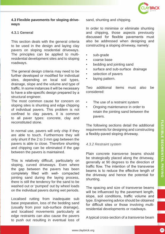
4.3 Flexible pavements for sloping drive-ways
4.3.1 General
This section deals with the general criteria to be used in the design and laying clay pavers on sloping residential driveways. The principles can be applied to multi-residential development sites and to sloping roadways.
The general design criteria may need to be further developed or modified for individual sites, depending on local soil types, drainage, slope and the volume and type of traffic. In some instances it will be necessary to have a site-specific design prepared by a structural engineer. The most common cause for concern on sloping sites is shunting and edge chipping of individual pavers. This problem is not confined to clay pavers, it is common to all paver types: concrete, clay and reconstituted stone.
In normal use, pavers will only chip if they are able to touch. Furthermore they will only shunt if the 2 to 3 mm gap between the pavers is able to close. Therefore shunting and chipping can be eliminated if the gap between the pavers is maintained.
This is relatively difficult, particularly on sloping, curved driveways. Even where the gap between the pavers has been completely filled with well- compacted jointing sand during the laying process, there is still the tendency for the sand to be washed out or ‘pumped’ out by wheel loads on the individual pavers during wet periods.
Localised rutting from inadequate sub base preparation, loss of the bedding sand (usually from poor sub-surface drainage), and localised movements particularly at edge restraints can also cause the pavers to push out resulting in eventual loss of
sand, shunting and chipping.
In order to minimise or eliminate shunting and chipping, those aspects previously discussed for flexible pavements must also be addressed when designing and constructing a sloping driveway, namely:
• sub-grade • coarse base • bedding and jointing sand • surface and sub-surface drainage • selection of pavers • laying pattern.
Two additional items must also be considered:
• The use of a restraint system • Ongoing maintenance in order to
retain the jointing sand between the pavers.
The following sections detail the additional requirements for designing and constructing a flexibly-paved sloping driveway.
4.3.2 Restraint system
Plain concrete transverse beams should be strategically placed along the driveway, generally at 90 degrees to the direction of traffic flow. The intention of the transverse beams is to reduce the effective length of the driveway and hence the potential for shunting.
The spacing and size of transverse beams will be influenced by the pavement length, slope, soil conditions, traffic volume and type. Engineering advice should be obtained for difficult sites or those involving multi-residential developments or roadways.
A typical cross-section of a transverse beam

www.claybrick.org www.claybrick.org 2524
FLEX
IBLE
SE
GM
EN
TAL PA
VIN
G
Flexible Segmental Paving
for a single dwelling is shown in Figure 7. These should be used where the length of the driveway exceeds about 7 m, and spaced at about 5 to 6 m.
Concrete used in edge restraints, transverse beams, kerb and gutters and drains should have a minimum compressive strength of 20 MPa at 28 days.
Pavers laid over transverse beams, edge restraints and around pits and grates should be laid as a header course set in a mortar of one part Portland cement to three parts washed sand.
4.3.3 Drainage
Surface drainage is not normally a problem on sloping driveways. However, inadequate or non-existent sub-surface drainage is a common cause of failure in all pavements, particularly on sloping driveways and roads.
It is very important to ascertain any locations along the length of the driveway where sub-surface water may accumulate and provide drainage outlets at these locations. If this is not done the water will make its own way out, eroding bedding and jointing sand.
Shunting and chipping is inevitable when this occurs.
Generally a drainage system must be provided where natural drainage through the sub-grade is not available or where sub-surface water is likely to pool or not drain freely under the pavers. Sub-surface water is likely to dam at the top side of transverse beams, the lower side of edge restraints, and at grates. Figure 8 shows typical drainage systems that can be adapted for these locations.
4.3.4 Laying pattern
Pavers should be laid in a 45 degree herringbone pattern. Due to its interlocking action this pattern provides the best interlock and resistance to shunting. Other patterns are not recommended for vehicular traffic.
4.3.5 Maintenance
It is critical to maintain the jointing sand between units in order to avoid movement that may result in paver shunting and/or chipping.
Figure 7 Typical plain concrete 230 mm wide transverse beam for a single residence driveway

www.claybrick.org www.claybrick.org 2524
FLEX
IBLE
SE
GM
EN
TAL PA
VIN
G
Flexible Segmental Paving
FLEX
IBLE
SE
GM
EN
TAL PA
VIN
G
Figure 8 Typical Drainage systems
This may require frequent ‘topping up’ of the jointing sand particularly after periods of heavy rain.
Pavers around drainage pits and service pits should be laid in header courses and set in a cement mortar, or a concrete surround used in lieu of the pavers. This reduces the erosion of sand by stormwater.
50-60
50-60
www.claybrick.org www.claybrick.org 2726
FLEX
IBLE
SE
GM
EN
TAL PA
VIN
G
Flexible Segmental Paving
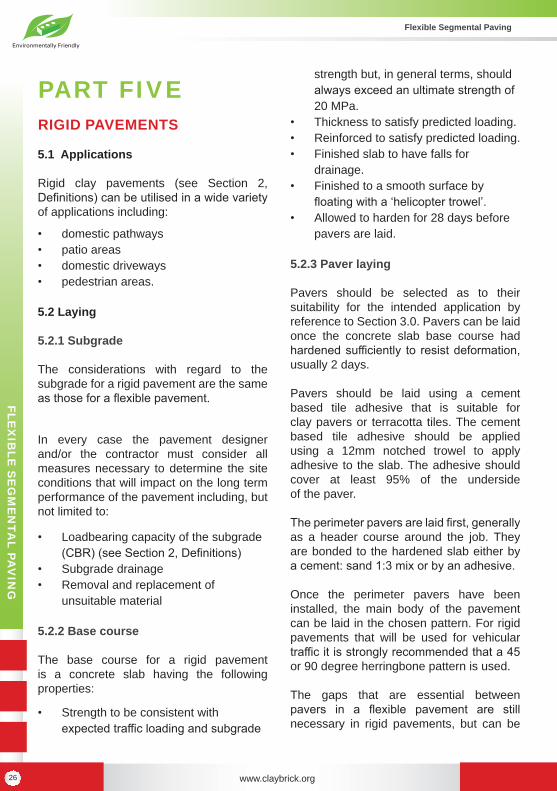
PART FIVERIGID PAVEMENTS
5.1 Applications
Rigid clay pavements (see Section 2, Definitions) can be utilised in a wide variety of applications including:
• domestic pathways • patio areas • domestic driveways • pedestrian areas.
5.2 Laying
5.2.1 Subgrade
The considerations with regard to the subgrade for a rigid pavement are the same as those for a flexible pavement.
In every case the pavement designer and/or the contractor must consider all measures necessary to determine the site conditions that will impact on the long term performance of the pavement including, but not limited to:
• Loadbearing capacity of the subgrade (CBR) (see Section 2, Definitions)
• Subgrade drainage• Removal and replacement of
unsuitable material
5.2.2 Base course
The base course for a rigid pavement is a concrete slab having the following properties:
• Strength to be consistent with expected traffic loading and subgrade
strength but, in general terms, should always exceed an ultimate strength of 20 MPa.
• Thickness to satisfy predicted loading. • Reinforced to satisfy predicted loading. • Finished slab to have falls for
drainage.• Finished to a smooth surface by
floating with a ‘helicopter trowel’. • Allowed to harden for 28 days before
pavers are laid.
5.2.3 Paver laying
Pavers should be selected as to their suitability for the intended application by reference to Section 3.0. Pavers can be laid once the concrete slab base course had hardened sufficiently to resist deformation, usually 2 days.
Pavers should be laid using a cement based tile adhesive that is suitable for clay pavers or terracotta tiles. The cement based tile adhesive should be applied using a 12mm notched trowel to apply adhesive to the slab. The adhesive should cover at least 95% of the underside of the paver.
The perimeter pavers are laid first, generally as a header course around the job. They are bonded to the hardened slab either by a cement: sand 1:3 mix or by an adhesive.
Once the perimeter pavers have been installed, the main body of the pavement can be laid in the chosen pattern. For rigid pavements that will be used for vehicular traffic it is strongly recommended that a 45 or 90 degree herringbone pattern is used.
The gaps that are essential between pavers in a flexible pavement are still necessary in rigid pavements, but can be

www.claybrick.org www.claybrick.org 2726
FLEX
IBLE
SE
GM
EN
TAL PA
VIN
G
Flexible Segmental Paving
FLEX
IBLE
SE
GM
EN
TAL PA
VIN
G
Figure 9. Section through typical rigid clay pavement.
smaller depending on the size/dimensional deviation of the pavers.
It must be noted that with this system there is no allowance for the variation in the depth or height of the pavers as they are being laid on a hardened concrete base. Therefore any variation in height of the units will show up in the finished pavement. Pavers that have a bevelled or rounded arris can disguise this variation.
5.2.4 Expansion joints
Expansion must be considered when laying a rigid pavement. The gaps between pavers in a flexible pavement allow for thermal and long-term moisture expansion of clay pavers to be taken up. In a rigid pavement this does not occur. Therefore expansion joints are required in rigid pavements. The paver manufacturer should be consulted for advice on the location of such expansion joints.
5.2.5 Joint filling
Once all the full and cut pavers have been laid it is time to fill the joints. The jointing mix is 1:3 cement: fine sand mixed with sufficient water to turn it into a fluid slurry. The mixture must be sufficiently fine so that the slurry mix can flow around any gaps in the paver and fill any voids underneath them.
Finally once the slurry filling of the joints is complete the surface of the pavers should be hosed down using a high-pressure, fine mist spray to remove the excess slurry.
Vehicular traffic should be prevented from traversing the pavement for at least four days.

www.claybrick.org www.claybrick.org 2928
FLEX
IBLE
SE
GM
EN
TAL PA
VIN
G
Flexible Segmental Paving
PART SIXMAINTENANCE
6.1 Early trafficking and cleaning
If the pavement has unbound joints, traffic may use the pavement immediately after the final pass of the vibrating plate compactor. Cleaning with hoses or powered vacuum cleaners is not recommended during the first three months of the pavement use. Cleaning should be by hand broom only during this period.
6.2 Basic cleaning principles
6.2.1 General
All pavements are subject to spillages and soiling and a build-up of dirt and grime. The careless use of cement- type materials during the laying of a pavement can also lead to soiling. Frequent sweeping and washing reduces the effect of dirt and grime and maintains the attractiveness of a pavement.
The removal of stains is not always easy but by following these principles and procedures the cleaning of a clay pavement need not be a problem.
6.2.2 Select correct cleaning chemicals
The first question should be: “Is the use of chemicals necessary?” If dry sweeping or washing with clean water and a detergent fails to bring the pavement to an acceptable state of cleanness, the answer could be “yes”.
However rather than automatically using
an acid cleaner such as hydrochloric acid, it is essential to identify the substance to be removed. Some useful hints to help you identify stains on pavements are given later. If this is not enough, consult your supplier or a professional knowledgeable in the subject.
6.2.3 Follow correct cleaning procedures
Follow the instructions given here or on the label of the selected proprietary cleaner. If you are inexperienced, test the selected chemical on a small, inconspicuous patch before tackling the whole pavement. This could save time and effort if, for instance, the method used or the chemical selected is not effective.
6.2.4 Safety precautions essential
There are few chemicals that are entirely safe and those used for cleaning paving are often potentially dangerous. A few elementary precautions are necessary:
• Protect yourself against inhaling dangerous fumes and against acid burns on your skin or in your eyes.
• Wear protective clothing. • Dilute acids in the open with the
breeze behind you. • Always add acid to water, NOT water
to acid.
While working with these chemicals, keep people (especially children) and animals out of the area. Upon completion ensure the chemicals are safely stored.
6.3. Removing common stains
6.3.1 Efflorescence
This is a powdery deposit of salts (usually white or yellow), often found on the surface

www.claybrick.org www.claybrick.org 2928
FLEX
IBLE
SE
GM
EN
TAL PA
VIN
G
Flexible Segmental Paving
FLEX
IBLE
SE
GM
EN
TAL PA
VIN
G
of clay pavers after rain. The source of this stain could be the pavers but more often it comes from the surrounding materials, for example the soil under the pavement, or from cement (if the soil was stabilised), or both. Efflorescence is usually harmless and can be removed by dry brushing and hosing. However sometimes it is necessary to follow this up with a wash of weak acid or a proprietary cleaner.
6.3.2 White scum Do not confuse this with efflorescence. White scum is a thin white film on the surface of pavers. This film is invisible when the pavers are wet but shows up as the surface begins to dry. It often appears after an attempted removal of mortar stains or after the sanding of the joints with a ‘clayey’ sand (that is, sand with a high clay content).
White scum is particularly difficult to remove. Water, detergents or hydrochloric acid often do not have any effect on it. However scrubbing with a proprietary cleaner will often improve the appearance of pavements affected by this stain.
6.3.3 Dirt and grime
Frequent sweeping and hosing will usually ensure a clean pavement. If this is not enough, washing with a detergent or proprietary cleaner may be required.
6.3.4 Vanadium stains
Light-coloured clays often contain vanadium salt that may appear as a yellow, green or reddish-brown discolouration of the pavers.
Vanadium stains are naturally occurring and are neither permanent nor harmful and do not indicate any defect in the pavers. Stains in exposed areas generally wash off in
time but their removal can be hastened by chemical treatment.
A number of treatments are available. It is best to test the efficacy of these chemicals on a test area to determine the most suitable treatment to use. Vanadium stains can be removed by:
a. Sodium hypochlorite. The active ingredient in household bleach and swimming pool chlorine, sodium hypochlorite is an inexpensive treatment for mild cases of vanadium staining. Spray or brush the chemical onto the stain without pre-wetting, allow it to stand until the stain disappears, and then rinse off.
b. Oxalic acid. Probably the best-known chemical for removal of vanadium stains. However it must be followed by a neutralising wash. If this action is omitted (as it commonly is) further staining of a serious nature can result. The correct procedure is:
• Mix 20 to 40grams oxalic acid per litre of water (preferably hot water).
• Apply to the stained pavers without pre-wetting.
• Neutralise the oxalic acid by applying a solution of 15grams of washing soda per litre of water. Do not wash off.
c. Potassium hydroxide Mix 150g of potassium hydroxide per litre of water and apply to the stained pavers. Leave until the stain disappears, then wash off. A white residue may appear after this treatment and this should also be hosed off.

www.claybrick.org www.claybrick.org 3130
FLEX
IBLE
SE
GM
EN
TAL PA
VIN
G
Flexible Segmental Paving
6.3.5 Fresh mortar stains
The simplest way to remove wet mortar is to lightly cover the pavement before the mortar sets hard, with clean, but slightly damp, washed sand. Sweep the sand towards the edges of the pavement. If necessary repeat this until the surface is almost clean. The most important point to remember is that the sand MUST be free of clay.
Follow up with a further sweep with dry washed sand. Any sticky wet mortar residues that escaped the wet sanding will be removed. Once again the sand must be free of clay.
One or two days after the pavement has dried, some mortar residues may still be visible as a faint white film. Normally this will weather away. The appearance of efflorescence is almost certain but do not panic, just follow the instructions above.
6.3.6 Hardened mortar stains
Experiment on a small section of the pavement with decreasing proportions of water mixed with hydrochloric acid, starting with one part of acid to ten parts of water.
Once you have determined the appropriate proportion of acid to water, the type of propriety cleaning solution needed, process as follows:
• Slightly wet the pavement with a fine spray of water
• Using a stiff brush, apply the acid over approximately one square metre. Vigorously scrub the areas stained with mortar. When scrubbing is not sufficient loosen thick mortar patches with a hard implement such as a steel scraper. Work on the mortar stain until
it is dissolved. • Give the area a good hose-down. A
pressurised water spray unit is useful for this job.
Repeat these steps until the whole pavement has been cleaned. A final rinse of the pavement with a high-pressure water jet is often beneficial. However there are some pavers that could be damaged by the overuse of high-pressure water jets. Care must also be taken not to remove sand from the paver joints.
6.3.7 Fungi, moulds, moss and lichens
These are common, particularly in shady or damp parts of the pavement. They sometimes appear as localised dark stains or patches of green, giving a dirty and unsightly appearance.
Alternatively these growths may add to the appearance of the pavement. They will not damage the pavement but may cause it to become slippery.
To remove these growths, vigorously brush the affected area when it is dry. High-pressure water may also be used. Although the surface may now appear to be completely cleaned it is necessary to sterilise the area with a poison or a strong fungicide that should be allowed three to four days to act. Blue crystals (copper sulphate) is one such poison whereas sodium hypochlorite (liquid chlorine or bleach) and formaldehyde are fungicides. Other proprietary brands are available from plant nurseries. The surface should be brushed again when dry.
Warning: Some of the poisons in fun-gicides may discolour the pavement. Check their effect on a small part of the pavement before proceeding to clean the whole area. Pay attention to nearby

www.claybrick.org www.claybrick.org 3130
FLEX
IBLE
SE
GM
EN
TAL PA
VIN
G
Flexible Segmental Paving
FLEX
IBLE
SE
GM
EN
TAL PA
VIN
G
garden plants or lawn, especially on the lower side of the paved area being treated.
6.3.8 Oil, bitumen and tar
These stains usually need two treatments with a commercial emulsifying agent. First, mix the emulsifier with paraffin to remove the stain. Then clean the parafinn off with the emulsifier mixed only with water.
When dealing with petroleum asphalt and bituminous emulsion, scrape off the excess material and scrub the surface with scouring powder and water.
For petrol or lubricating oil stains, free oil must be mopped up immediately with an absorbent material such as paper towelling. Wiping should be avoided as it spreads the stain and tends to force the oil into the pavement. Hardened oil must be scraped off.
The area affected should then be covered with a dry absorbent material such as diatomaceous earth, fine white clay, kaolin or whiting and the procedure repeated until there is no further improvement. Subsequently use detergent to clean up, and rinse well with clean water.
6.3.9 Food stains and tyre marks
Scrub with a full-strength commercial detergent and rinse well.

www.claybrick.org www.claybrick.org 3332
FLEX
IBLE
SE
GM
EN
TAL PA
VIN
G
Flexible Segmental Paving
PART SEVENREFERENCES
1. SANS 1575: 2007 - Burnt Clay Paving Units
2. Think Brick Australia Manual 1 Clay Paving Manual ISBN 0-947160-06-X

www.claybrick.org www.claybrick.org 3332
FLEX
IBLE
SE
GM
EN
TAL PA
VIN
G
Flexible Segmental Paving
FLEX
IBLE
SE
GM
EN
TAL PA
VIN
G