CLASS 323 DRIVERS MANUAL - ttweb.co.uk · · 2013-10-03are fitted together with a wheel...
56
1 CLASS 323 DRIVERS MANUAL
Transcript of CLASS 323 DRIVERS MANUAL - ttweb.co.uk · · 2013-10-03are fitted together with a wheel...

1
CLASS 323
DRIVERS MANUAL

2
LIST OF CONTENTS
SUBJECT MATTER PAGE NUMBER TRAIN DATA AND GENERAL INFORMATION 2-5 EXTERNAL EQUIPMENT 6-7 DRIVING COMPARTMENT 8-15 INTERIOR EQUIPMENT 16-17 GETTING UNDER WAY 18-23 AUXILIARIES 24 AIR SYSTEM 25 PREPARING A TRAIN FOR SERVICE 26-30 DISPOSAL INSTRUCTIONS 30-31 DRIVING INSTRUCTIONS 31-32 FAULT FINDING 33-43 ISOLATING SAFETY SYSTEMS 43-44 FAILURE OF DRIVING/BRAKE CONTROLS 45 COUPLING AND UNCOUPLING 46-47 ASSISTANCE PROCEDURES 47-49 EFFECTS OF CIRCUIT BREAKERS TRIPPING 50-51 OPERATING THE PARKING BRAKE 52 SANDING INSTRUCTIONS 53 DOOR OPERATION 54-56 PASSENGER ENVIRONMENT 56
TRAIN DATA AND GENERAL INFORMATION Type Class 323 electric multiple unit trains are formed into three-car standard class sets. Built by Hunslet TPL these units work suburban services around Manchester and Birmingham. Units are numbered from 323 201 to 323 243 of which numbers 323 223 to 323 239 are run by Northern Rail. Power Equipment Trains have three phase ac induction motors powered by inverters producing a variable voltage and frequency three phase ac supply, derived from the single-phase 25kv overhead line supply. The three phase traction motors incorporate automatic slip/slide control in both traction and braking. Auxiliary supplies are derived from an auxiliary converter. Train data 1 All car bodies’ lightweight aluminium. 23 metres long. 2 Max speed 90 mph. 3 Doors sliding plug type and electrically operated. 4 Air suspension. 5 Public address. 6 Electronic external destination displays. 7 Gangways between vehicles in a set only.

3
Vehicle types Driving Motor Standard (DMS) 1 Driving car with a driving compartment at one end. 2 Carries a traction converter with a three phase traction motor on each axle. 3 Cars are designated “A 64 car” and “B 65 car”. DMS A is nearest to the pantograph. Trailer Standard (TS) 1 Carries the following equipment- pantograph, main transformer, auxiliary converter, auxiliary compressor, main compressor and main air reservoir tank. 2 Toilet and external toilet waste tank. 3 72 car. Other train features 1 Train equipment with vigilance and pass comm override facility. 2 On Train Data Recorder. (OTDR) 3 Parking brake spring applied. 4 Service braking is by regenerative braking which is backed up by air operated three step electrically controlled “Westcode” type. 5 Enhanced Emergency braking. 1) Air braking This is Davies and Metcalfe EBC/5 three step automatic electrically controlled ‘energise to release’ air brake with enhanced emergency braking. Disc brakes are fitted together with a wheel slip/slide system. The air brake uses a ‘brake continuity wire’ forming the electrical equivalent of the air brake pipe. Brake continuity wire must be energised to release the brakes and if de-energised for any reason, brakes apply immediately (e.g. a door is opened when the train is moving). 2) Regenerative braking When braking is selected, the traction motors are made to act as AC generators, producing current which is fed back to the overhead line to be used by other trains. Generating current in this way produces a retarding effect on the traction motor rotors which acts through the traction motor gearing to individual wheels and gradually slows them down. The regenerative braking circuits ensure that the braking effect produced in the motors matches the braking rate selected by the driver. If the overhead line cannot accept the current, there will be no regenerative effect. The braking circuitry detects this and switches automatically to normal air braking. Any shortfall in braking effect is made up progressively blending in the air brakes. 3) Parking brake The parking brake is spring applied and automatically applies if main reservoir pressure is lost. It will release automatically when main reservoir pressure rises above 4.5 bar. A parking brake isolating cock is provided(adjacent to the foot well on assistants side and behind a flap) can be used to manually apply and release the parking brake(if main air pressure is available). This is covered further on in this manual.

4
TRAIN DATA AND GENERAL INFORMATION Train formations Typical three car formation: DMS (A)-TS-DMS(B). Up to 4 units can operate in multiple. Coupling Tight lock fully automatic couplers at driving compartment ends (no side buffers). Inter-car coupling with bar couplers. Driving compartment The driving compartment is ergonomically designed. Its main features are: Controls zoned according to function. Equipment least used by the driver furthest away from the seat. Combined power and brake controller with an integral hill start button to hold the train when starting on a gradient. Train and unit fault indicators to pinpoint faults. Train equipped with vigilance and pass comm override facility. Interior equipment Fault indication panel (FIP) All cars have a “FIP”. They are located on the driver’s mcb panel and in a vestibule cupboard, non-toilet end of the TS car. Pantograph air system The pantograph air system is located in the TS car in two areas: The pantograph auto drop isolating cock (ADD) and VCB isolating cock are located inside a “Pan air system” cubicle alongside the emergency equipment cupboard. The pantograph isolating cock and earthing switch are inside a roof panel immediately above the door to the emergency equipment cupboard. Environment panel Each car has an environment panel incorporating saloon temperature controllers. Vestibule cupboard Located at both ends of the TS car and the non-driving ends of each DMS. The TS car cupboards contain mcb’s for some control circuits, lights and the auxiliary compressor. Emergency equipment Train safety equipment is located in each driving compartment. All other emergency equipment is in the emergency equipment cupboard on the TS car. Fire extinguishers are located in the passenger saloons at DMS “D” and TS “B” doors and in the drivers cab.

5
Isolating cocks Air system isolating cocks for horns and wipers/washers (DMS cars only) are located behind a panel in the foot well on the assistant’s side of the cab. Exterior equipment All power, air and auxiliary exterior equipment are located in cases mounted on the under frame. Air system isolating cocks are mostly grouped together on a “brake frame assembly”. The TS vehicle carries the main transformer. It has an associated “transformer fault” indication panel. Also located on the TS are the “brake frame assembly” and “pantograph auxiliary compressor frame”. Front end This section describes the external equipment on the train starting with the front end. Note the following items of interest: Emergency coupling point isolating cock (ESIC) used when coupling a Schrader emergency air hose to the unit. Drum switch-isolating cock (DIC). Turns the air and electrical connections ON and OFF between units if needed. Main reservoir pipe isolating cock. Located to the left of the drum switch. Drum switch lever and positions of use to the driver. The tail lamp bracket is hinged off the coupler support bar. The bracket folds up when required.

6
EXTERNAL EQUIPMENT Air system isolating cocks External air system isolating cocks on both DMS and TS are grouped together on a “brake frame assembly”. The cocks are located behind protective covers and which can be opened with a gated carriage key. TS cars have an additional “pantograph & auxiliary compressor frame" with similar isolating cocks, also under cover. Locations of the various external cocks are shown as follows: DMS brake frame ASIC Air suspension isolating cock bogie 1 (not used now) ASIC Air suspension isolating cock bogie 2 (not used now) BIC Brake cylinder isolating cock ASIC Air suspension supply isolating cock BSRIC Brake supply reservoir isolating cock TS brake and air supply frame CGIC Compressor governor isolating cock BIC Brake cylinder isolating cock MRIC Main reservoir isolating cock BSRIC Brake supply reservoir isolating cock TS pantograph & auxiliary compressor frame ASIC Air suspension supply reservoir isolating cock PRIC Air supply to the pantograph reservoir(labelled MRIC wrongly on unit) ASIC Air suspension reservoir isolating cock bogie 1(not used now) ASIC Air suspension reservoir isolating cock bogie 2(not used now) Other traction equipment The TS car carries the main transformer. A “Transformer Fault” indication panel is mounted nearby on the auxiliary converter case.

7
EXTERNAL EQUIPMENT DMS Car Brake Frame A Low Main Air Governor E Blending Valve B Brake Supply Reservoir Governor F Re-gen Brake Control Unit C Isolating Cock Manifold G Sand box filler D 3 Step Brake Control Unit H Sander test push button TS Car Main Compressor and Brake Frame
A Compressor Governor E 3 Step Brake Control Unit B Low Main Air Governor F Blending Valve C Brake Supply Reservoir Governor G Re-gen Brake Control Unit D Isolating Cock Manifold H Main Reservoir TS Car Main Compressor and Brake Frame
A Isolating Cock Manifold B Auxiliary Compressor Governor
A B C D E F G H
A B C D E F G H
A B

8
DRIVING COMPARTMENT Entering the driving compartment To enter the driving compartment from the outside unlock the door using a gated carriage key (note indicator change from red to green). The crew door access handle can now be operated, the door can then be opened manually. The cab door should always be opened/closed electrically from inside the driving compartment. To open from the inside Press the cab door release button. Keep depressed until the door unlocks and unplugs you must then open the door by pushing it open. To close from the inside Press the door close button until the door powers closed. To close from the outside Press the door close button until the door powers closed. To close from the outside on disposal of the unit Pull the door closed and lock it by using your gated carriage key. To operate manually Release the safety flap and use the internal manual door control handle alongside the door, or the external crew door access handle. Operating either handle will mechanically release the door mechanism so the door can be opened by hand. After operating either handle, the door control mechanism must be reset by moving the internal manual door control handle back to the horizontal position and the safety flap closed. The door cannot be powered closed until this handle has been reset.

9
DRIVING COMPARTMENT Controls on the Drivers Left The left hand side control panel is shown below 1- Lights on push button. 2- Auxiliaries on push button 3- Lights off push button 4- Auxiliaries off push button 5- Re-gen brake switch. 6- Door key switch and indicator. 7- Door close push button. 8- Signal push button. 9-Door release push buttons. 10-General fault indicator. 11-Emergency brake push button.
1 2
3 4
5 6
7 8
9
10
11

10
DRIVING COMPARTMENT Power and braking controls 1- Master key slot 2- Master switch (4 positions OFF, FORWARD, NEUTRAL & REVERSE ) 3- Combined power and brake handle Insert a master key to move the switch away from off and select off to remove it. Moving the master switch away from off will enable the drivers controls to be operated and sound an alarm if two master switches are in use together. If the master switch is moved to neutral when the train is moving at more than 3 mph or if moved to off when the train is moving, the brakes will automatically apply. The combined power/brake handle is inter locked with the master switch and has the following features: a 3-step brake with emergency brake facility which is worked by pushing controller forward and a four notch power controller which is worked by pulling the handle back. A “gate” is provided to prevent you going from power straight to braking. A push button in the handle gives a brake step one which can be used for hill starts but is only operative up to 6 mph when it is then automatically released.
1
2 3

11
DRIVING COMPARTMENT Instrument panel, left hand side 1- Proving indicators for headlights, marker lights and tail lights. 2- Tail lights switch. 3- Marker lights switch (4 positions off, day head ,marker lights and night head.) 4- Battery charge indicator. 5- On Train Data Recorder indicator. 6- Line volts indicator. 7- VCB indicator. 8- Pan up/reset push button 9- Pan down push button 10-Main reservoir and Brake reservoir gauges
Instrument panel, right hand side 1 Safety systems isolated indicator 2 Hazard warning push button indicator 3 Door interlock indicator 4 Pass-com alarm override push button 5 Doors close push button 6 TPWS reset push button 7 Door release push buttons, right hand side doors 8 TPWS audible alarm and sunflower indicator 9 Sanders push button 10 Speedo 11 DRA and isolating switch
1
2
3
4 5
6
7
8 9
10
11
10
8
1 2 3
6 7
4 5 9

12
Right hand control panel 1 Cab heater switch (heat 1, vent and heat 2). 2 Cab lights switch. 3 Windscreen demist switch. 4 Wind screen wiper/windscreen washer control. 5 Couple push button. 6 Uncouple push button(covered by a flap). 7 Horn control. 8 NRN Radio. 9 On train telephone hand set and NRN hand set. 10 Communications push buttons. Yellow - “PA” press to select public address. Red - Press to talk to passenger at pass-com location. Blue - “Cab-Cab” for cab to cab communication. 11 TPWS control panel.
Other controls 1 Digital clock 2 Emergency brake push button (When pushed, latches on and applies the brake, to release twist to the left and restore to the normal position).
Assistant’s side of the driving compartment 1 Fire extinguisher 2 OTDR console 3 Manual Door release
11
10
9
8
7
5 6
2
1
1
2
1
2 3
4 3

13
Safety systems isolating switches panel 1 Isolating switches 2 Door close push button 3 Signal buzzer 4 Door release push buttons 5 TPWS Temporary Isolating Switch Isolating switches have two positions: normal and isolated. To operate- remove master switch and insert key in desired switch, then turn to the isolated position. The safety systems isolated light will illuminate on the drivers instrument panel. These can only be reset by the maintenance staff.
Isolating Switches 1 ATP (isolated as unit not fitted) 2 AWS 3 EBS 4 PASS COMM 5 TIS 6 VIGILANCE 7 DSD
1
2 3
4
5
1 2 3 4 5 6 7

14
DRIVING COMPARTMENT MCB’s top row
Fault indication panel All cars have a fault indication panel (FIP) located below the driving compartment mcb panel in DMS cars and at the pantograph end of the TS car located in a cupboard on the left hand side. The FIP will only be operative when the master switch is in the off position, a fault will be indicated by the red indicator being illuminated along with the general fault indicator located by the drivers master switch. 1- Brake reservoir fault 2- Earth fault 3- Local fault 4- Traction fault 5- Wheel slide fault
More details on the exact workings of the fault indicator panel and associated faults are covered in full detail further on in this manual in the “Faults and Failures” section.
15
Parking brake isolating cock Pictures below show the location of the parking brake isolating cock, if isolated the associated flap will not close. Instructions regarding the operation of this cock are covered further on in this manual. flap down flap raised
Horn and wiper isolating cocks Next to the parking brake is a cupboard which houses isolating cocks or the horn and wipers, below shows the labelling of the cupboard, the isolating cocks are behind and further instructions for the isolation of these cocks are covered further on in this manual.
INTERIOR EQUIPMENT Vestibule cupboards Each car has at least one vestibule cupboard containing either an environmental panel, mcb panel, fault indication panel or pantograph / vcb panel. Environment panels Location DMS (non-driving end) and TS (toilet end). Picture below shows an environmental panel with its various indications. Further information is available further on in this manual as to their working.

16
INTERIOR EQUIPMENT Fault indication panel (TS car) The fault indication panel is situated at the non-toilet end and will only be operative when the drivers master switch is in the off position. A fault will be indicated by the red indicator being illuminated. The indications shown below are as follows: Auxiliary converter fault Brake reservoir fault Local fault Transformer fault Wheel slide fault Note that two of the indications are not used
MCB control panel (TS car) This panel is situated at the non-toilet end opposite the fault indication panel cupboard. Below shows how the mcb’s are laid out and also the auxiliary compressor push button, which is located in this cupboard. This can be used to start the auxiliary compressor when on preparation the unit could be low on voltage.

17
Toilet control panel This is located in a cupboard inside the toilet and picture shows how the mcb’s are laid out.
Pantograph air system The pantograph air system is located in two areas shown below.
1- The pantograph automatic drop isolating cock (PADIC) and vacuum circuit breaker isolating cock (VCB) are located inside a “pan air system” cubicle alongside the emergency equipment cupboard.
2- The pantograph isolating cock and earthing switch are inside a roof panel immediately above the door to the emergency equipment cupboard.
Pan isolating handle VCB isolating Cock PADIC isolating cock
2
1
2
18
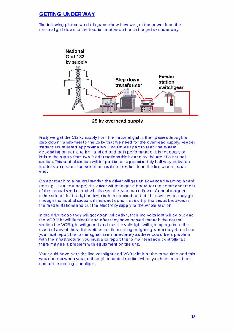
GETTING UNDER WAY The following pictures and diagrams show how we get the power from the national grid down to the traction motors on the unit to get us under way. Firstly we get the 132 kv supply from the national grid, it then passes through a step down transformer to the 25 kv that we need for the overhead supply. Feeder stations are situated approximately 30/40 miles apart to feed the system depending on traffic to be handled and train performance. It is necessary to isolate the supply from two feeder stations this is done by the use of a neutral section. This neutral section will be positioned approximately half way between feeder stations and consists of an insulated section from the live wire at each end. On approach to a neutral section the driver will get an advanced warning board (see Fig 13 on next page) the driver will then get a board for the commencement of the neutral section and will also see the Automatic Power Control magnets either side of the track, the driver is then required to shut off power whilst they go through the neutral section, if this is not done it could trip the circuit breakers in the feeder stations and cut the electricity supply to the whole section. In the drivers cab they will get as an indication, their line volts light will go out and the VCB light will illuminate and after they have passed through the neutral section the VCB light will go out and the line volts light will light up again. In the event of any of these lights either not illuminating or lighting when they should not you must report this to the signalman immediately as there could be a problem with the infrastructure, you must also report this to maintenance controller as there may be a problem with equipment on the unit. You could have both the line volts light and VCB light lit at the same time and this would occur when you go through a neutral section when you have more than one unit ie running in multiple.
National Grid 132 kv supply
Step down transformer
Feeder station switchgear
25 kv overhead supply
19
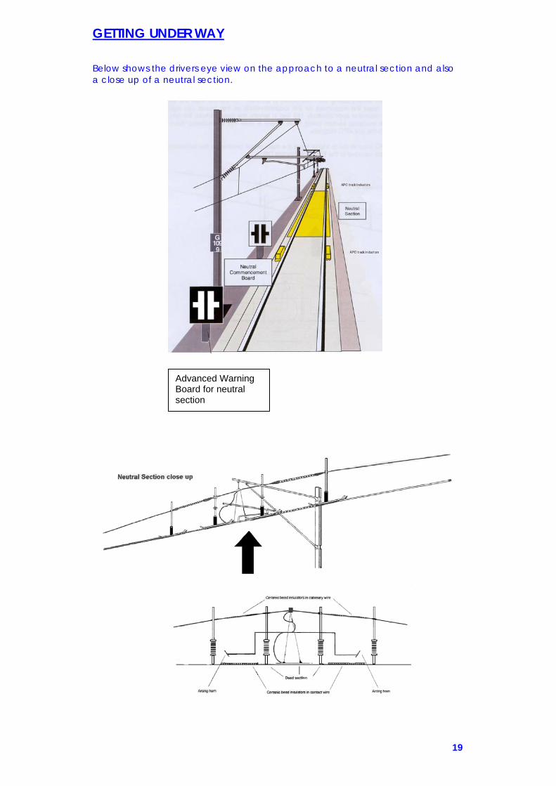
GETTING UNDER WAY Below shows the drivers eye view on the approach to a neutral section and also a close up of a neutral section.
Advanced Warning Board for neutral section

20
GETTING UNDER WAY Each neutral section is 155 feet long and is split up into the following sections, firstly there is a 100 foot run on, this is from the first APC magnet to the insulated section, secondly there is 15 feet of dead section, which is split in to 5 feet of ceramic insulators then 5 feet of dead section then another 5 feet of ceramic insulators and lastly there is a 40 foot run off, this is from the end of the insulated section to the second APC magnet. Drivers view of neutral section
Coming to a stand in a neutral section Should a train inadvertently come to a stand in a neutral section the following procedure should be adopted, dependant where in the neutral section the train has stopped? Pantograph between the entrance APC magnets and the 15 foot dead section After liaising with the signaller the train must be driven back out of the neutral section in the direction from which it came, to a distance, which will allow it to be driven back through the neutral section. Before moving a pan up reset will be required to reset the VCB. When the unit passes over the APC magnet the VCB will trip again, so another reset will be needed, the unit can then pass through the neutral section as normal. Pantograph between the 15 foot dead section and the exit APC magnets A pan reset will be required to reset the VCB, the train can then be driven out of the neutral section but the VCB will trip again when the unit reaches the exit APC magnets therefore another reset will be required. Pantograph within the 15 foot dead section Unless the unit can roll out of the section, assistance will be required. If the movement is in the wrong direction then the signaller’s permission must be given.

21
GETTING UNDER WAY Having now got the electricity from the national grid in to the overhead power lines we need to get the electricity in to the train to give us the power required to move the train, this is done by use of a pantograph which collects the electricity from the overhead and sends it to a transformer on the train to reduce it to a voltage that we can work with. The pantograph fitted to the unit is a Brecknell Willis high speed pantograph, below are diagrams and pictures.

22
GETTING UNDER WAY Below shows a basic diagram of the pantograph air system and associated isolating cocks. An auxiliary compressor runs when the battery supply is switched on and builds up enough air to enable the pantograph to be raised, once the pantograph is up an auxiliary compressor governor tells the auxiliary compressor to stop and the air is then fed in to the system from the main air system. An isolating cock is provided to prevent the pantograph from being raised (i.e. if it has suffered damage ). An isolating cock is also provided for the automatic dropping device (ADD ), instructions for the operation of this are covered further on in this manual. These isolating cocks are situated in the TS car in the roof and opposite the cupboard which contains the mcb’s.
VCB
VCB Isolating Cock (red) ADD isolating Cock (padic) Both located In cupboard
Pantograph Isolating Cock located In roof
Auxiliary Compressor and pantograph reservoir Main
Reservoir Air supply

23
GETTING UNDER WAY Having now got the pantograph up and in contact with the overhead wire, the 25kv a.c. passes through the pantograph in to the main transformer which is situated on the TS car see. Here it reduces the voltage through a series of windings to a more manageable level of 1,500v a.c. for traction power and also a feed of 240v a.c. for the auxiliaries on the unit. The transformer is oil cooled therefore any problem with the cooling of this oil will result in the overheating of the transformer and a resulting loss of power and the unit being a failure (see fault finding section).
The diagram below shows how the electricity is distributed from the transformer to the two traction converters, the stages it goes through changing it from single phase A.C. to three phase A.C. to enable us to get power to the traction motors on each DMS. We have four traction motors on each DMS , one above each axle, giving us a total of eight traction motors on the unit all together.
Pic 40 shows a traction converter and where it is located on the unit.
NOTE WHEN PREPARING A UNIT THE DRIVER MUST OBSERVE THE AREA AROUND AND UNDERNEATH THE TRANSFORMER FOR ANY POSSIBLE SIGNS OF OIL LEAKS AND MUST NOT MOVE THE UNIT UNTIL THE MAINTENANCE STAFF HAVE BEEN CALLED AND CHECKED OUT THE FAULT.

24
AUXILIARIES A feed of 240 volts AC is taken from the main transformer and is used for certain auxiliaries on the unit, it also passed then to the auxiliary converter on the TS car which converts it to 110 volts DC for all the main auxiliaries on the unit. Picture shows the auxiliary converter and table shows the auxiliary circuit
240 VOLTS AC COMES FROM THE TRANSFORMER AND SUPPLIES THE AUXILIARIES LISTED IN BLUE IT ALSO PASSES TO THE AUXILIARY CONVERTER WHICH CONVERTS
THE 240 AC TO 110 DC FOR ALL THE MAIN AUXILIARIES LISTED IN RED WSP EQUIPMENT
POWER / BRAKE CONTROLLER
VOLTAGE TRANSFORMER
TRANSFORMER OIL PUMP
DOOR CONTROL EQUIPMENT
AUXILIARY COMPRESSOR
SALOON HEATING
CLEANERS SOCKETS
SALOON LIGHT INVERTERS
CAB LIGHTS
RETENTION TANK HEATER
CAB HEATING
BRAKE UNIT HEATERS
EMERGENCY LIGHTING
TOILET FAN EXTRACTION
IMMERSION HEATER
DESTINATION INDICATORS
PA PASS COMM CAB TO CAB
MAIN COMP RECTIFIER
CONVERTER CASE FAN
AWS DSD VIGILANCE
NRN RADIO
BATTERY CHARGER

25
AIR SYSTEM
On the 323 we need air for such things as brakes, suspension, sanders, pantograph system, horn and wipers. The first stage of this is an auxiliary compressor which runs when the auxiliaries are set, this runs and builds up enough air to get the pantograph raised. (Note if there is no air at all in the system the VCB light will flash and the brake res fault light will be lit, when there is enough air the VCB will stop flashing and the brake res fault light will go out.). Once the pantograph is up the main compressor kicks in and feeds air to the main reservoir tank, which is situated behind the main compressor frame on the TS car. The compressor runs between 8.5 and 10.5 bar it does this by means of a governor which tells it when to start and stop. The compressor governor has an isolating cock which is situated on the main compressor frame on the TS car, this will enable the compresssor to run all the time, but to do this we need a safety valve which blows off at 10.7 bar to stop the reservoir building up and up, which would eventually result in the tank blowing. Air is then fed from the main reservoir tank via the main reservoir pipe (coloured yellow) to the brake supply reservoir and the air suspension reservoir on each car. It is also fed to the pantograph reservoir on the TS car, the sanding equipment on both DMS cars and the horn and wipers in each cab. The air that is in the main reservoir pipe is fed round the system at 7 bar this can be observed by the driver on the main reservoir and brake gauge in the cab. When the driver wants to apply the brakes, train wires are de-energised which determines how much air is fed from the brake supply reservoir to the brake cylinders.
AUXILIARY COMPRESSOR
AUXILIARY COMPRESSOR GOVERNOR 0 TO 6.5 BAR
TO RAISE PANTOGRAPH
PANTOGRAPH RESERVOIR
MAIN COMPRESSOR
COMPRESSOR GOVERNOR 8.5 TO 10.5
BARMAIN
RESERVOIR TANK
SAFETY VALVE SET at 10.7
BAR
7 BAR FEED VALVE
MAIN RESERVOIR PIPE MAIN RESERVOIR PIPE
LOW MAIN GOVERNOR
6.2 BRAKES WILL NOT RELEASE
6.7 BRAKES WILL RELEASE
*STATIONARY HORN AND WIPERS BRAKE SUPPLY RESERVOIR
PARKING BRAKE SPRING
APPLIES AT LESS THAN 4.5 BAR.
BRAKE SUPPLY RESERVOIR GOVERNOR
5.2 LOSS OF POWER EMERGENCY BRAKE
APPLICATION 6.3 GOVERNOR WILL SET
**ON THE MOVE**
SANDERS
AIR SUSPENSION
BRAKES

26
PREPARING A TRAIN FOR SERVICE Approach the unit and check for
1- Not to go boards 2- Scotches 3- Any cables or hoses
In the driving cab carry out or check
1- Power/brake handle at step 3 2- Insert master key 3- Master switch to neutral 4- Check repair book 5- Press “aux on” button 6- Reset AWS warning 7- VCB will illuminate
While Auxiliary compressor charges system carry out or check
1- Re-gen brake switch ON 2- Tail lights 3- Day/night/marker lights 4- Hazard warning lights 5- Set destination indicator 6- PBIC access panel is closed 7- Safety system isolation switches normal (except ATPIS which is isolated) 8- Assistants door emergency door release (egress) manual handle at reset 9- Fire extinguisher 10- Track circuit clips 11- Flag and detonators 12- Uncouple bar 13- Mcb’s set 14- Traction control cut out switch at normal 15- Drivers door egress manual handle at normal
MAKE ONE COMPLETE CIRCUIT OF THE TRAIN AND REPEAT THE FOLLOWING INSTRUCTIONS AS NECESSARY LOOK FOR ANY OBVIOUS DAMAGE OR DEFECTS AND ENSURE THERE ARE NO SCOTCHES IN POSITION THEN CHECK: Front
1- Tight lock coupling 2- Electrical connection box 3- ESIC with dust plug fitted 4- Drum switch 5- Main reservoir pipe isolating cock
DMS assistants side
1- Cab door manual egress handle 2- Saloon door manual egress handle
Between DMS & TS
1- Jumper cables 2- Earthing strap

27
TS Car
1- Toilet retention tank cover 2- Isolating cock panel 3- Pantograph
Between TS & DMS
1- Main reservoir pipe 2- Brake cylinder gauge registering
DMS drivers side
1- Check sanding equipment (test & isolating cock) 2- Isolating cock panel 3- Saloon door manual egress handle 4- Cab door manual egress handle
Rear or between coupled units if in multiple carry out or check
1- Tight lock coupler 2- Electrical connection block 3- Butterflies (additional feature to check if properly coupled) 4- ESIC & dust plug 5- Drum switch 6- Main reservoir isolating cock
Re-enter driving cab carry out or check
1- Press pan up to raise pantograph 2- Line light illuminates 3- VCB light extinguishes 4- Pass comm alarm light extinguished 5- Main air reservoir pressure rising 6- Master switch off 7- Remove master key 8- Brake cylinder pressure is established and holding 9- Switch interior lights on
In the rear cab or any intermediate cab if in multiple carry out or check
1- Repair book 2- Re-gen brake on 3- Power/brake controller at brake step 3 4- Tail lights (leave on in rearmost cab) 5- Day head light 6- Marker lights 7- Night head light 8- Hazard warning lights 9- Windscreen washer/wiper 10- Horn 11- NRN radio 12- PBIC access panel is closed 13- Safety systems isolations switches normal (except ATPIS which is not fitted) 14- Assistants door manual egress handle at reset 15- Fire extinguisher 16- Track circuit clips 17- Flag and detonators 18- Uncouple bar 19- MCB’s set 20-Traction cut out switch normal 21-Drivers door manual egress handle at reset

28
In rearmost driving cab carry out a brake test Carry out a test of the brakes and observe the brake cylinder pressure at each stage
1- Insert master key 2- Master switch to neutral 3- TPWS will go through its self test 4- Reset TPWS warning 5- Select forward 6- Press DSD pedal 7- Select emergency position 8- Select brake step 3 9- Select brake step 2 10- Select brake step 1 11- Select brake off momentarily and return to step 1 12- Hill start button (test with brake at off ) 13- Select brake step 3 14- Both emergency plungers 15- DSD 16- DRA 17- Master switch off, remove master key and return to the leading cab
Walk through train to the rear cab and check
DMS car
1- Fire extinguisher 2- Emergency door release handles normal 3- Emergency hammers
TS car
1- MCB panel 2- Pan IC cover & Pan equipment cover (PADIC & VCB ) 3- Emergency equipment cupboard glass seal 4- Local door panel closed 5- Fire extinguisher 6- Emergency door release handles normal 7- Emergency hammers
DMS car
1- Fire extinguisher 2- Emergency door release handles normal 3- Emergency hammers

29
In the leading driving compartment Carry out a test of the brakes and observe the brake cylinder pressure at each stage
1- Insert master key 2- Master switch to neutral 3- TPWS will go through its self test 4- Reset TPWS warning 5- Select forward 6- Press DSD pedal 7- Select emergency position 8- Select brake step 3 9- Select brake step 2 10- Select brake step 1 11- Select brake off momentarily and return to step 1 12- Hill start button (test with brake at off ) 13- Select brake step 3 14- Both emergency plungers 15- DSD 16- DRA 17- Master switch to neutral
Finally carry out or check
1- Head and marker lights on as needed 2- Windscreen washer/wiper 3- NRN radio 4- Check the horn
Door test The conductor must carry out a test of the power operated doors, if the train is running under Driver Only Operation (DOO) it will be the drivers duty to do this. Instructions regarding this are covered in the next section. Drivers additional duties when D.O.O. If the train is to be prepared under DOO conditions you must carry out the following additional checks:
1- In the leading cab operate the door key switch (DKS) to on 2- Obtain door release on ONE side of the train 3- Check that an emergency brake application is given 4- Check driving desk door interlock light is red 5- Enter passenger compartment and proceed to the rear of the train 6- Operate passenger door open buttons at each door on both sides of the
train (checking opposite side do not open) 7- Check pass comm alarms 8- Return to the front cab checking all window hammers are present 9- Enter front cab and check that all external hazard lights are illuminated
along both sides of the train 10- Operate the door close button 11- Check blue door interlock light is illuminated on driving desk 12- Check all exterior hazard warning lights are out 13- Carry out buzzer test 14- Operate DKS switch to off 15- Repeat for opposite side and return through the train

30
Preparing a train for another driver
1- Carry out preparation duties as normal then put power/brake controller to step 3
2- Check that brake cylinder pressure is established and holding 3- Master switch to off and remove drivers key 4- Leave cab and close and lock driving cab doors
Taking over a prepared train
1- Before proceeding carry out or check power/brake controller to step 3 2- Insert master key and select neutral 3- Reset TPWS warning
Changing ends In the original driving cab, carry out or check
1- Select brake step 3 2- Brake cylinder pressure is established 3- Master switch to off and remove master key 4- Brake cylinder pressure is established and holding 5- Head and marker lights off 6- Tail lights on 7- Cab lights off 8- Close windows 9- Close and lock driving cab doors
Proceed to the new driving cab, carry out or check
1- Power/brake controller at brake step 3 2- Insert master key 3- Master switch to neutral 4- Reset TPWS warning 5- Select brake step 1 6- DSD 7- Tail lights off 8- Head and/or marker lights on (as applicable) 9- Destination indicator
DISPOSAL INSTRUCTIONS In the leading driving compartment, carry out or check
1- Brake step 3 2- Brake cylinder pressure is established 3- Master switch off 4- Remove master key 5- Brake cylinder pressure maximum and holding 6- Head and marker lights off 7- Tail lights on 8- Check general fault light 9- Check fault indicator panel 10-Close windows 11-Lock doors 12-Cab lights off

31
Enter the saloon and walk to the rear cab and check the fault indication panel in the TS car In the rear driving compartment, carry out or check
1- Fault indicator panel 2- Brake cylinder pressure maximum and holding 3- Tail lights off (unless required) 4- Saloon lights off 5- Repair book entries (if required) 6- Lower pantograph 7- Cab lights off 8- Auxiliaries off (unless pantograph raised/tail lights required) 9- Close windows 10- Leave the driving cab and lock the doors
DRIVING INSTRUCTIONS
Driving in yards or depots before entering service
1- Insert master key and select neutral 2- Before moving look around carefully to ensure that no other vehicles or
equipment is foul or will foul train 3- When the train is ready to start with all doors closed press the DSD pedal,
select a direction and reset the DRA (if applicable) 4- Move the power/brake controller to power notch 1 and acknowledge the
starting signal if accompanied by a conductor 5- To prevent the train rolling backwards on a rising gradient press the hill
start button 6- When the train starts to move, release the hill start button and increase
power as required (NOTE: if the hill start button is not released, when the train reaches 6 mph the brakes will automatically release)
7- Remember the direction selector switch must only be moved when the train is stationary. Power must NOT be applied if the train is moving in the opposite direction to that selected by the master switch
Driving in service
1- When the train is ready to start with all the doors closed press the DSD pedal, select a direction and reset the DRA (if applicable)
2- Select power notch 1 and acknowledge the starting signal, if maximum acceleration is required and railhead conditions permit, select power notch 4, going through the other notches slowly.
3- To prevent the train rolling backwards on a rising gradient press the hill start button
4- When the train starts to move, release the hill start button and increase power as required (NOTE: if the hill start button is not released, when the train reaches 6 mph the brakes will automatically release)
5- Remember the direction selector switch must only be moved when the train is stationary. Power must NOT be applied if the train is moving in the opposite direction to that selected by the master switch
WARNING- BEFORE ATTEMPTING TO MOVE THE TRAIN IT MUST HAVE BEEN FULLY PREPARED EITHER IN ACCORDANCE WITH THE DRIVERS STATIC DUTIES, OR TAKEN OVER FROM ANOTHER DRIVER IN A FULLY PREPARED CONDITION.

32
DRIVING INSTRUCTIONS
Stopping 1- Normal braking. Move the power/brake handle to off and select the
required braking notch as shown in Northern Rail braking instructions 2- Emergency braking. It is always possible to move the power/brake handle
to the emergency position regardless of the position of the master switch. When the emergency brake position has been used the brakes will then not be released until the train reaches a speed below 3 mph. An extra 1 bar of air pressure is given when selecting the emergency brake position
Operation of the parking brake The parking brake is spring applied and held off by main reservoir air pressure. The parking brake applies automatically when the main reservoir air pressure falls below 4.5 bar. The parking brake releases automatically when main reservoir air pressure rises above 4.5 bar. Manual operation of the parking brake is covered further on in this manual.
FAULT FINDING DATA
Defects
Report all defects by making an entry in the unit defect book at the end of duty or if the problem is serious enough straight away and give a supervisor a copy of the entry, who will fax it to maintenance control to arrange fitters attention. If possible a phone call to the unit controller or the maintenance controller may help the situation. Be accurate when reporting defects, as this will assist the maintenance staff when trying to rectify a defect. If the unit is prevented from coming off a maintenance depot, maintenance control must still be advised and the person in charge of operations at the depot must also be advised.
Fault finding procedure Call the signalman and tell him you have a problem and carry out the appropriate rules and regulations. Has a circuit breaker tripped (MCB)? If so try and reset it but not more than three times. If there is no obvious cause check the following table for possible causes, ask for assistance immediately if there is any doubt about rectifying the fault. When you know what the problem is contact the signalman and say how long the train will be delayed, if possible. When the defect is rectified make sure traction power is available and all systems working before starting. When assistance is required due to the complete failure of the train it will not be necessary to request assistance if there is more than one unit. The failed train can be assisted by the other unit providing there are no defects, which would prevent this. The driver must obtain the services of the conductor as required if needed to ride in the leading cab for such actions as sounding the horn or applying the parking brake in an emergency.

33
FAULT FINDING DATA
FAULT POSSIBLE CAUSE LOCATION ACTION Battery charge light red (battery not charging)
Auxiliary converter failed
TS car Take unit out of service as soon as possible you may only have 40 mins running time.
Auxiliary control MCB tripped
TS car MCB panel Try to reset MCB. If unable to reset take unit out of service as soon as possible you may only have 40 mins running time.
Battery charge light out (loss of 110v DC supply)
Auxiliary supply MCB tripped
TS car MCB panel Try to reset MCB. If unable to reset request assistance as unit will be a complete failure.
VCB indicator light flashing
Pantograph automatic dropping device (ADD) operated
TS car Follow instructions headed ADD further on in this manual.
VCB indicator light illuminated
Traction control MCB tripped
TS car MCB panel Try to reset MCB. If unable to reset request assistance as unit will be a complete failure.
Air leak in pantograph air system
TS car Press pan down; isolate pantograph and trip PRIC and request assistance.
Transformer primary overload
TS car auxiliary converter
Try pan up reset 3 times if VCB doesn’t go out request assistance unit is a failure.
Transformer over temperature
TS car auxiliary converter
Unit failure request assistance.
Bucholz relay TS car Unit failure request assistance.
VCB isolated TS car Contact maintenance staff on preparation.
Line volts and VCB indicator lights both out
Overhead line equipment is off
TS car Check with signaller
Flat batteries TS car Assistance will be required to provide 110v DC supply

34
Pantograph will not rise
Auxiliary compressor will not run
TS car Press the auxiliary compressor button on the TS car MCB panel for 2 mins or use another 323 to provide main air pressure to charge the pan air system.
Pantograph is isolated
TS car roof panel Check with maintenance staff.
Air leak in pan air system
TS car Press pan down; isolate the pan and request assistance.
Loss of traction power
Traction fault DMS car See instructions regarding traction control in the MCB section of this manual.
Main reservoir pressure falls or does not rise
Main compressor not running
TS car Check compressor control MCB-if OK then isolate compressor governor isolating cock. Compressor will now run continuously. Ensure safety valve operates at 10.7 bar. If still fails to operate request assistance as unit is a failure.
Main reservoir is isolated
TS car on main compressor frame
If isolated return to normal position
Leak or burst on air suspension system
Any vehicle Follow instructions for isolating air suspension, which are covered further on in this manual.
Leak or burst on the brake supply reservoir
Leading DMS car Isolate the brake supply reservoir isolating cock; the vehicle now has isolated brakes. You need either assistance from the front who must raise there EBS, if possible drive back the way you have just come but you must raise your EBS and proceed at a safe reduced speed due to the last vehicle having isolated brakes.

35
Main reservoir pressure falls or does not rise (cont)
Leak or burst in brake supply reservoir
DMS car (not leading) or TS car
Turn Brake Supply Reservoir Isolating Cock (BSRIC) to the isolate position. The vehicle must now be regarded as having “isolated brakes”. The EBS must be isolated and the driver must proceed in accordance with Rule Book section TW5. Train may now run at a safe reduced speed.
Leak or burst in main reservoir tank
TS car Turn MRIC (brake equipment and air supply frame) to the “Isolate “ position, trip the Compressor Control MCB (TS car) MCB panel and request assistance.
Leak or burst on main reservoir pipe
Leading DMS car Close both main reservoir pipe coupling cocks (MRPCC) between leading DMS and adjoining TS. Isolate and release the brakes on the DMS car. Maintenance staff must attend to release the parking brakes. The train must then be assisted…a. From the front by another 323 and the assisting driver must isolate the EBS and close MRPCC between trains.

36
Main reservoir pressure falls or does not rise (cont)
Leak or burst on main reservoir pipe (cont)
Leading DMS car b. Assistance from the front or rear by other than a 323 you must isolate the brakes on the whole of the train and proceed at 5 mph. c. Or if possible change ends and return in the direction you have just come you must isolate the EBS to get the brakes off and proceed at a safe reduced speed due to what is now the last vehicle having isolated brakes.
TS car Close main reservoir pipe coupling cocks (MRPCC) on both ends of the TS car. Trip the compressor Control MCB (TS car MCB panel) The train must be assisted a. From the front by another class 323 and the assisting driver must isolate the EBS. The brakes must be isolated and released on all affected vehicles in rear of the defective TS car, maintenance staff must also attend to release the parking brakes on these vehicles. Proceed at 5mph.

37
Main reservoir pressure falls or does not rise (cont)
Leak or burst on main reservoir pipe (cont)
TS car (cont) b. from the front or rear other than a 323, the brakes must be isolated and released on all vehicles and maintenance staff must attend to release the parking brakes on all vehicles not receiving a supply of main reservoir air. Proceed at 5mph.
DMS car (not leading)
Close main reservoir pipe coupling cocks (MRPCC) on the end (both ends if multiple) of the DMS car. The driver must isolate the EBS in the leading cab and isolate and release the brakes on the DMS car. Proceed at safe reduced speed.
Unable to release brakes or brake application in service
AWS defective (now known as TPWS)
Leading DMS car Reset AWS (now known as TPWS) MCB. If unable to reset, isolate the AWS (TPWS) isolating switch and proceed in accordance with section TW5 of the drivers rule book (clause 2.10).
DSD defective Leading DMS car Isolate DSD and VIS isolating switches and proceed in accordance with section TW5 of the drivers rule book (clause 2.10).

38
Unable to release brakes or brake application in service
Vigilance defective Leading DMS car Isolate the VIS isolating switch and proceed in accordance with section TW5 of the drivers rule book (clause 2.10).
Power/Brake controller placed to emergency
All cabs Restore to brake step three position, if unable to, you will have to isolate the EBS isolating switch to release the brakes.
Emergency brake plunger operated
All cabs Restore plunger to normal position (white line vertical), if unable to, you will have to isolate the EBS isolating switch to release the brakes.
EBS isolated in rear driving cab
Rearmost DMS car Isolate EBS in leading driving cab.
Train brake MCB tripped
Leading DMS car If unable to reset the train brake MCB the train must be assisted a. from the front by another 323 and the assisting driver must isolate the EBS (no special speed restriction) b. from the front or rear by other than a 323 and the brakes on the whole train must be isolated. Proceed at 5mph. c. Or if possible change ends and return in the direction you have just come you must isolate the EBS to get the brakes off.

39
Unable to release brakes or brake application in service
Train brake MCB tripped (cont)
DMS car (not leading)
If unable to reset the MCB you will need to isolate the EBS to release the brakes.
Train Control MCB tripped
Leading DMS car If unable to reset the MCB, the driver must drive from another cab and the conductor (competent person) must ride in the leading driving cab, operate the warning horn and apply the brake in an emergency. Proceed at 20mph.
Doors open or not properly closed
All Request the conductor to press the door close button again, reset any emergency door release handle that may have been operated, lock any defective doors out of use and if still unable to release the brakes or gain power, you must isolate the EBS then the TIS and proceed in accordance with the drivers rule book section TW5 (clause 2.10).
Train Door Control MCB tripped
All cars If unable to reset the MCB, lock any defective door out of use, you must then isolate the TIS and proceed in accordance with the drivers rule book section TW5 (clause 2.10).

40
Unable to release the brakes and passcom alarm light flashes
Two or more units are not coupled correctly
All DMS cars Check the drum switches are in the “couple air and electric” position, if not operate them manually.
Two or more master switches
All DMS cars Place any master switch that is not in use to “off” and remove any master key.
Brakes apply or will not release on one car only
Dragging brakes All Secure train, locate defective car (use smell, signs of heat etc.) Check the parking brake (PBSIC) in each DMS car and is in the “normal” position (note: there is no PBSIC in the TS car). If the parking brake cannot be released, maintenance staff must attend to manually release them. If brakes are simply dragging, isolate them and run at a safe reduced speed.

41
Brakes apply or will not release on one car only
Local brake MCB tripped (and speedometer to zero on that car)
Leading DMS car If unable to reset the MCB you must isolate the brakes on the leading DMS to exit the cab you must open the cab door manually as you lose electrical control to the local cab door when you re-enter the driving cab you must lock the cab door, then isolate the EBS to release the brakes on the rest of the train and proceed at a safe reduced speed and act in accordance with the drivers rule book section TW5 (clause 2.10).
DMS car (not leading)
If in multiple move the master switch to the “off” position and check that the Wheelslide fault indicator is lit then check which car has the local fault light lit. If unable to reset the MCB, isolate the brakes on the relevant car and proceed at a safe reduced speed and act in accordance with the drivers rule book section TW5 (clause 2.10).
Pass comm alarm light flashes with no immediate brake application
Pass comm operated
Any vehicle See the information regarding the pass comm system which is covered further on in this manual.
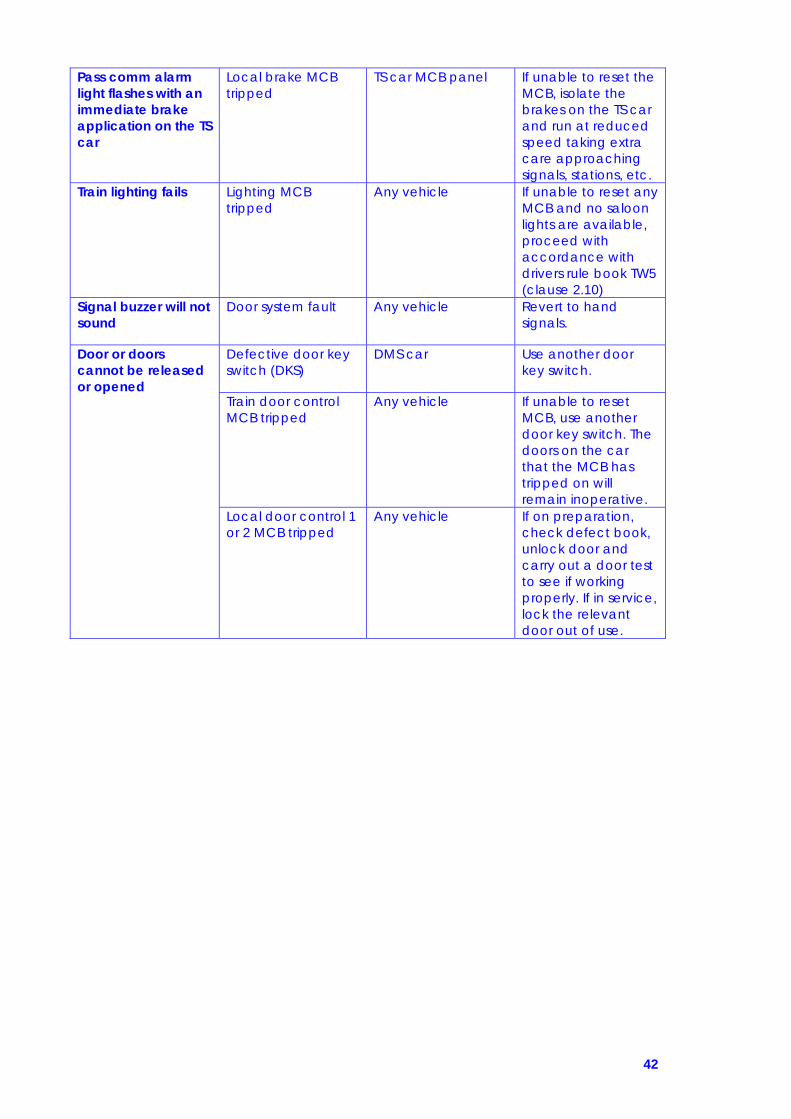
42
Pass comm alarm light flashes with an immediate brake application on the TS car
Local brake MCB tripped
TS car MCB panel If unable to reset the MCB, isolate the brakes on the TS car and run at reduced speed taking extra care approaching signals, stations, etc.
Train lighting fails Lighting MCB tripped
Any vehicle If unable to reset any MCB and no saloon lights are available, proceed with accordance with drivers rule book TW5 (clause 2.10)
Signal buzzer will not sound
Door system fault Any vehicle Revert to hand signals.
Door or doors cannot be released or opened
Defective door key switch (DKS)
DMS car Use another door key switch.
Train door control MCB tripped
Any vehicle If unable to reset MCB, use another door key switch. The doors on the car that the MCB has tripped on will remain inoperative.
Local door control 1 or 2 MCB tripped
Any vehicle If on preparation, check defect book, unlock door and carry out a door test to see if working properly. If in service, lock the relevant door out of use.

43
Door or doors will not close
Train door control MCB tripped
Any vehicle If unable to reset MCB, use another door key switch. The doors on the car that the MCB has tripped on will remain inoperative.
External or internal emergency door release handle
Any vehicle Reset any emergency door release handle then close the door and lock it out of use.
Door obstructed, jammed or damaged
Any vehicle Rectify any problem then close the door and lock it out of use.
Signal buzzer sounds continuously
Two or more master switches in use
DMS car Place all master switches other than the one in use to “off” and remove any driver’s keys.
Two or more door key switches in use
Any vehicle Place all other door key switches not in use to “off”.
Cleaners shore supply socket at ”on”
TS car If no shore supply is attached place switch to “off”.
ISOLATING THE SAFETY SYSTEMS Safety systems isolating switches Located in the right hand side (assistants side) of the driving compartment. They are from top to bottom:
ATPIS Automatic train protection system (not fitted so permanently isolated AWSIS Automatic warning system (now known as TPWSIS) EBS Emergency bypass switch PCIS Pass com system TIS Traction interlock switch VIS Vigilance system DSDIS Drivers safety device
Isolating switches have two positions, normal and isolated. To operate them you must remove your master key and insert in the desired switch, turn the switch to the isolated position. When a safety system has been isolated the safety systems isolated indicator will light on the instrument panel. These switches can only be reset by the maintenance staff. Refer also to drivers rulebook section TW5.
The TPWS temporary isolation switch is situated below these switches and is sealed.

44
ISOLATING THE SAFETY SYSTEMS Pantograph automatic dropping device (ADD) Units are fitted with a pantograph automatic dropping device (ADD) and an associated isolating cock (PADIC) fitted in the pan air system cubicle on the TS car. The ADD will drop the pantograph automatically if the pantograph carbons are displaced or the pantograph head is damaged, this is to minimise damage to the overhead line equipment. If the device operates, the line light will go out and the VCB light will flash, if this happens you must: 1- Press the pan down button (to open the VCB) 2- Stop immediately, inform the signalman and examine the pantograph for
signs of damage to any component parts (if possible stop in a cutting or under a bridge to assist you in viewing the pantograph).
3- If there are signs of damage to any of the pantograph equipment you must isolate the pantograph and request assistance.
4- If there is no sign of damage, you must contact maintenance control for authority to raise the pantograph, you can only do this by isolating P.A.D.I.C. Once isolated the pantograph will not drop if the A.D.D. operates again, authority will not be given if it is obvious there is damage to the carbons. Authority will only be given for the train to proceed a short distance to a maintenance depot and at reduced speed.
5- If permission is given to raise the pantograph you must check the pantograph again when it comes into contact with the overhead line equipment. You must proceed in accordance with the instructions given and also act in accordance with the drivers rule book section AC3.
WARNING IF THE DRIVER FINDS P.A.D.I.C. ISOLATED ON PREPARATION OF THE UNIT YOU MUST INFORM MAINTENANCE CONTROL IMMEDIATELY AND DO NOT MOVE THE UNIT WITHOUT AUTHORITY YOU MUST ALWAYS REMEMBER TO ISOLATE THE PANTOGRAPH WHEN BEING ASSISTED DUE TO ANY FAULT, THIS IS DUE TO THE FACT THAT THE ASSISTING DRIVER COULD ATTEMPT A PAN RESET FOR WHAEVER REASON AND THIS WOULD RAISE THE PANTOGRAPH ON YOUR UNIT ALSO, WITH THE OBVIOUS CONSEQUENCES (FOR EXAMPLE IF YOU HAD DAMAGED CARBONS THIS COULD CAUSE EVEN MORE DAMAGE TO THE OVERHEAD LINE EQUIPMENT)

45
FAILURE OF DRIVING OR BRAKE CONTROLS Defective driving/braking equipment on preparation A class 323 unit must not leave a maintenance depot to enter passenger service with:
1- An isolated or ineffective brake on any vehicle 2- Defective / inoperative driving/ brake controls in any driving
compartment Additionally, when entering service from off other than a maintenance depot, the provisions of the drivers rule book section H must be observed. Defective driving/braking controls in service When driving equipment in the leading cab becomes defective during a journey, but brake continuity is available you will need to drive from another cab (if in multiple another forward facing cab), you will have to be aware of the following: If you are the driver
1- Drive and brake the train from the most convenient driving cab 2- Drive at reduced speed 3- As far as practicable, observe all signals 4- Be prepared to act promptly on competent persons signals
If you are the competent person
1- Ride in the leading driving compartment 2- Keep a good lookout 3- Observe all signals 4- Signal to driver as necessary using buzzer 5- Sound the horn when necessary 6- If needed stop the train in an emergency 7- Detrain passengers at first convenient location
IN ALL CIRCUMSTANCES YOU WILL BE FOLLOWING INSTRUCTIONS GIVEN TO YOU AND ACTING IN ACCORDANCE WITH THE DRIVERS RULE
BOOK SECTION TW5 CLAUSE 2.10.

46
COUPLING & UNCOUPLING On a general note, if possible try to couple and uncouple on plain straight line, with no curves or gradients. If the coupling procedure does not go smoothly, step by step, then the units must be separated and the procedure run through again – any deviation from the standard procedure is not accepted, as this indicates that there may be a coupling fault, and the whole procedure must work in one attempt. If the procedure fails repeatedly, then inform maintenance control and work to their instructions. As is the case with any unit problems, fill out the repair book and inform control. To Couple: Stop 2 metres short of the unit Look in window of unit for non-multi sign Put brake on unit you’re driving to emergency Put direction selector to neutral Get out of unit, and check:
Coupler heads are in alignment Electrical box covers are intact Any obvious damage to coupler Coupler piston is down (where manual uncouple bar socket is) At least one set of jaws is open – if not, then press the uncouple button to
open them Get back in unit Draw up to 60 cm short of unit and stop Draw on to unit, coasting at no more than 2 mph After contact, apply brake Place direction selector to reverse Take power in notch 2 Feel for resistance – this is known as a pull away test Put direction selector to neutral, and brake into step 2 Press couple button for 5 seconds Put direction selector to for/rev and release brake to step 2 Put direction selector to neutral Go to cab of other unit and check brake gauge reading is at step 2 – this is a brake continuity test, as you have now established that there is through brake control Turn off all end lights in other cab Check butterfly indicators are out on back of both couplers – if only one is out, then units are not coupled, and must be separated and the procedure run through again Ensure all marker/head/tail lights are off, and secure the cab. Units are now coupled. To uncouple: With direction selector in neutral, and brake in step 3, press uncouple button for 5 seconds. Put direction selector to reverse, take power in notch 1 and separate units by no more than 60 cm. Ensure correct lighting is on both units. Check that brake reading is maintaining in separated unit, and secure cab. Check that the couplers have no obvious problems e.g. electrical box cover stuck down. Units are now uncoupled.

47
Problems when Coupling If you are unable to couple the units, it may be that the units are on a curve or a gradient that is too great for the gathering horns to cope with. Ask for permission to move the units a short distance, and attempt to couple from there. Alternatively, in on Longsight, it may be necessary to run round the units and couple at a different end. A common fault is that the drum switch does not go over when the couple button is pressed. It is not acceptable to operate this by hand – the units must be separated, and the whole procedure ran through again. If you are unable to couple from one unit, try from the other. Problems when Uncoupling If you are unable to uncouple the units, it could be the same problems as above. Try easing up on the coupling. Once the uncouple button has been pressed, the units are then electrically separated, so you no longer have through brake control. This means that if you take power, you will only take power on the unit you are driving from, and the brakes will be in emergency on the other unit. So, it is safe to take power, notch 1 or 2, and when the unit pushes onto the opposing unit press the uncouple button at the same time. You will feel and hear the mechanical component of the tight lock coupler disengage, so then move the power controller to off – don’t brake, or the couplers may catch each other again. The units will then separate from each other, and you can stop 60 cm away. If this is unsuccessful, then an attempt at manual uncoupling can be tried, using the manual uncoupling bars. If this also fails, then contact maintenance control and work to their instructions. If on Longsight, they may authorise you to re-couple electrically with the couple button, and move the units down the road to plainer track to uncouple from there. If you are unable to uncouple from one unit, try from the other.

48
ASSISTANCE PROCEDURES Trains which can assist a 323
1- Another 323 2- Another train with a Tight lock auto coupler or buckeye coupling 3- A locomotive or multiple unit fitted with an emergency adapter coupling 4- A locomotive with a match vehicle
Trains a 323 can assist
1- Another train provided the failed train is not composed of a greater number of vehicles than its own formation
2- The failed train can be mechanically coupled to the 323 3- The failed train weighs no more than the 323 4- At least 50% of the traction motors of the 323 are working satisfactorily
Coupling trains with tight lock auto couplers and connection blocks Brake continuity available (323 assisted by a 323) Trains can be assisted from the front or rear with no special speed restrictions. If driving controls are inoperative, but the brake can be applied in an emergency in the leading cab and assistance is given from the rear, maximum speed must not exceed 20 mph. The driver of the failed train must ride in the leading cab, to sound the horn and control the movement if possible by the buzzer but if not then by the cab-cab communication and hand signals. Brake continuity NOT available between the two trains but brake continuity available WITHIN each train (323 assisted by 313-323)
1- Train can be assisted from the front or rear. 2- Leave both drum switches in the “uncoupled” position – do not press the
couple button. 3- If the failed train cannot maintain its own air supply, connect both the
“Schrader” emergency hoses between the failed train and the assisting train and open the ESIC cocks on both units.
4- Driver of the failed train must turn the master switch to the direction of travel and press and hold down the DSD pedal.
5- Maximum speed must not exceed 5 mph. 6- Carry out the instructions given and act in accordance with the drivers
rule book section TW5 clause 2.10.
WARNING
THE ISOLATION OF THE EBS WILL RENDER THE POWER/BRAKE CONTROLLER AND THE EMERGENCY BRAKE PLUNGERS INOPERATIVE IN ALL DRIVING
CABS IN THE TRAIN EXCEPT THE POWER/BRAKE CONTROLLER IN THE CAB WHERE THE ASSISTING TRAIN IS BEING DRIVEN FROM

49
Brake continuity NOT available between the two trains and the brakes are NOT operational on the failed train
1- Train can be assisted from the front or the rear 2- Leave both drum switches in the “uncoupled” position – do not press the
couple button. 3- When the assisting train is coupled, isolate the brakes on the failed 323. 4- If the failed train cannot maintain its own air supply, connect both the
“Schrader” emergency hoses between the failed train and the assisting train and open the ESIC cocks on both units.
5- Driver of the failed 323 must ride in the leading cab ready to operate the parking brake isolating cock.
6- Maximum speed must not exceed 5 mph. 7- Carry out the instructions given and act in accordance with the drivers
rule book section TW5 clause 2.10. Coupling trains with Tightlock auto couplers(no connection blocks) or with buckeye couplers If the failed train brakes are operational
1- The train can be hauled or propelled. 2- Drum switches (if fitted) must be in the uncouple position. 3- If the failed train cannot maintain its air supply, connect the “Schrader”
emergency air hose between the failed train and the assisting train and operate the ESIC on the failed 323 and the MRPIC on the assisting train.
4- Driver of the failed train must turn the master switch to the direction of travel and press and hold down the DSD pedal.
5- Maximum speed must not exceed 5 mph. 6- Carry out the instructions given and act in accordance with the driver’s
rulebook section TW5 clause 2.10. If the failed train brakes are NOT operational
1- The train can be hauled or propelled. 2- Drum switches (if fitted) must be in the uncouple position. 3- If the failed train cannot maintain its air supply, connect the “Schrader”
emergency air hose between the failed train and the assisting train and operate the ESIC on the failed 323 and the MRPIC on the assisting train.
4- When the assisting train is coupled, isolate the brakes on the brakes on the failed 323.
5- Driver of the failed train 323 must ride in the leading cab, ready to operate the parking brake isolating cock.
6- Maximum speed must not exceed 5 mph. 7- Carry out the instructions given and act in accordance with the drivers
rule book section TW5 clause 2.10.
IMPORTANT NOTE
When the Tightlock to buckeye emergency adaptor coupling equipment is required, this must be fitted only by the maintenance staff
who must specially attend for this purpose.

50
EFFECTS OF CIRCUIT BREAKERS TRIPPING This table shows the effects of all the mcb’s tripping on the unit, refer to the fault finding data table in this manual for the drivers actions should you be unable to reset the mcb. Only attempt a reset 3 times. Driving Compartment
MCB NAME EFFECT OF IT TRIPPING AWS Loss of power and emergency brake application. ATP Equipment is not fitted Local brake Emergency brake application on this car only, speedo to
zero, pass comm. flashes which you can over ride Train brake Loss of power and emergency brake application. Pass
comm. flashes and cannot over ride. Cab door Loss of electrical control to door can still be opened
manually Train door control Loss of door control from this cab Local door control 1
Loss of passenger doors A & D on this car
Local door control 2
Loss of passenger doors B & C on this car
Traction control Loss of power and regen brake on this car Train control Loss of power and emergency brake application (dead
desk ) Comms equipment
Loss of PA, NRN, Cab to Cab and pass comm. phones
Destination indicator
Loss of control to destination indicator
Fault indicators Loss of local fault panel, door interlock light, battery charge light & pass comm indicator and alarm
Cleaners socket Loss of 240 volts supply for cleaners equipment Earth fault Fault on 110 volt DC supply DO NOT RESET Report
immediately Heating control Loss of saloon heaters Demister No demisting of the windscreen Auxiliary lights 1 Loss of day headlight, 1 tail light, 1marker light and cab light Auxiliary lights 2 Loss of night headlight, 1 tail light, 1 marker light and
instrument lights Saloon lights 1 Loss of 40% of lights in saloon Saloon lights 2 Loss of 40% of lights in saloon Emergency lights Loss of remaining 20% of saloon lights
51
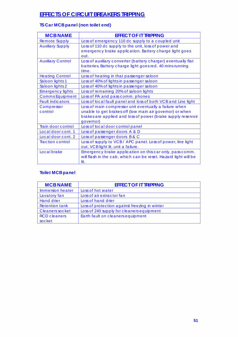
EFFECTS OF CIRCUIT BREAKERS TRIPPING TS Car MCB panel (non toilet end)
MCB NAME EFFECT OF IT TRIPPING Remote Supply Loss of emergency 110 dc supply to a coupled unit Auxiliary Supply Loss of 110 dc supply to the unit, loss of power and
emergency brake application. Battery charge light goes out.
Auxiliary Control Loss of auxiliary converter (battery charger) eventually flat batteries. Battery charge light goes red. 40 mins running time.
Heating Control Loss of heating in that passenger saloon Saloon lights 1 Loss of 40% of lights in passenger saloon Saloon lights 2 Loss of 40% of lights in passenger saloon Emergency lights Loss of remaining 20% of saloon lights Comms Equipment Loss of PA and pass comm. phones Fault indicators Loss of local fault panel and loss of both VCB and Line light Compressor control
Loss of main compressor unit eventually a failure when unable to get brakes off (low main air governor) or when brakes are applied and loss of power (brake supply reservoir governor)
Train door control Loss of local door control panel Local door cont. 1 Loss of passenger doors A & D Local door cont. 2 Loss of passenger doors B & C Traction control Loss of supply to VCB / APC panel. Loss of power, line light
out, VCB light lit, unit a failure. Local brake Emergency brake application on this car only, pass comm.
will flash in the cab, which can be reset. Hazard light will be lit.
Toilet MCB panel
MCB NAME EFFECT OF IT TRIPPING Immersion heater Loss of hot water Lavatory fan Loss of air extractor fan Hand drier Loss of hand drier Retention tank Loss of protection against freezing in winter Cleaners socket Loss of 240 supply for cleaners equipment RCD cleaners socket
Earth fault on cleaners equipment

52
OPERATING THE PARKING BRAKE Parking brake operation The parking brake automatically releases when the main reservoir pressure has risen above 4.5 bar. It will automatically be applied by a spring when main reservoir pressure falls below this. If the driving controls are inoperable due to the failure of equipment, the parking brake can be applied and released manually using the following procedure: Applying the parking brake
1) Go to the parking brake supply isolation cock in the driving cab 2) Close the parking brake isolating cock, air pressure then vents from
parking brake cylinder and the spring applies the parking brake 3) Once applied the parking brake will not release without an air
supply Releasing the parking brake If air pressure is available, turn parking brake isolation cock back to the normal position, air pressure will compress parking brake springs and the brakes will release Operating the parking brake with an emergency air supply
1) Go to the emergency equipment cupboard in the TS car 2) Remove the Schrader emergency air hose 3) Connect it to the main reservoir pipe hose of an assisting traction
unit 4) Plug it in to the Schrader connection on the front of the 323 5) Open the emergency supply isolating cock (ESIC) on the unit and
the main reservoir cock on the assisting traction unit allowing the air system to be charged
6) Provided there is sufficient air pressure and the parking brake isolating cock is in the normal position, the parking brake will release
7) Close the ESIC and remove the emergency air hose
NOTE THE COVER PROTECTING THE PARKING BRAKE ISOLATING COCK WILL NOT CLOSE IF IT HAS BEEN OPERATED

53
SANDING INSTRUCTIONS Sanding equipment has been fitted on all Class 323’s to assist the driver during periods of low adhesion. A sand test button has been fitted to the right of the brake frame on each DMS along with a sand box filler see, this is to be depressed on preparation of the unit to prove the sanders are working, to achieve this the driver must have the direction switch away from off. An isolation switch is provided in the cab for any fault through the computer or W.S.P equipment, in the event of isolation the flap will not close, a unit must not come off a depot with either the equipment isolated or the seal broken.
An isolation of the sanding equipment can be achieved in the event of either the sanders jamming on or a burst on any pipe on the system, this is done by turning the S.A.S.I.C. (sanding air supply isolating cock) to the vertical position, this is located to the left of the DMS brake frame. In the event of the driver experiencing poor railhead conditions a sander button is provided in the cab to be used when wheel slip is being detected by the W.S.P. equipment when starting away.
When wheel slide is being detected by the W.S.P under braking conditions, sanders will operate automatically. Sand is applied to the 3rd wheel set on each D.M.S.

54
DOOR OPERATION Door description
1) Saloon doors are double leaf sliding plug type and electrically operated
2) Two pairs of doors on each side 3) Driving cab doors are single leaf, sliding plug with one on each
side, they are electrically operated 4) Doors can be locked out of use with a carriage key 5) Doors can be opened if no electrical power is available 6) Door release will not be effective until train has come to a stand. 7) If a door is opened whilst the train is moving an emergency brake
application will be initiated Door operation Door controls are energised by turning the door key switch (DKS) on. The doors can now be released by pressing the two red door open push buttons simultaneously on the selected side of the train. When a door release is given:
1) an external orange hazard light shows on both sides of the train 2) passenger door open buttons light up 3) an emergency brake application is initiated as long as the master
switch is still in forward Passengers can now open and close the doors themselves with the internal door open and close push buttons, there is an external door open push button on each set of double doors. WARNING- THE DOORS MUST NOT BE RELEASED UNTIL THE TRAIN HAS COME TO A STAND Once platform duties are complete and the doors are ready to be closed, you press the blue door close push button, when pressed:
1) the light in the passenger door open buttons will go out 2) the audible hustle alarm will sound to warn passengers the doors
are about to close 3) any doors that are open will now close 4) hazard lights will go out, except for car where local door is open 5) once local door is closed last remaining hazard light will go out
and brakes will release 6) buzzer can now be given
NOTE: DOOR INTERLOCK LIGHT ONLY WORKS WHEN YOU HAVE YOUR DRIVERS KEY IN. (ie on preparation)

55
DOOR OPERATION
1- Emergency door release handle 2- Pass comm. handle 3- Door open and close buttons Opening the doors in an emergency The doors can be opened from the inside in an emergency using the green emergency door release handle situated above the doors behind a glass cover. It can be operated even when the train is moving, however the doors will not release until the speed of the train falls below 3 mph. When the handle is operated the doors have to be manually opened, hazard light will illuminate on vehicle concerned, emergency brake application will be initiated which cannot be over ridden. WARNING- IN THE EVENT OF PASSENGERS TRYING TO GET OFF THE TRAIN IN AN EMERGENCY MAKE THEM AWARE THERE ARE NO EXTERNAL STEPS BELOW THE DOUBLE LEAF DOORS To reset the emergency door release you insert a carriage key in a key hold in the door header above each passenger doorway. Door header in close up
1) Door out of service lock 2) Red door locked indicator 3) Emergency door release handle 4) Emergency door release reset 5) Pass comm. handle 6) Pass comm. reset
If you need to lock doors out of use for whatever reason, go to the door concerned and insert a carriage key in the key hole the internal and external door out of order signs will illuminate. Once the door is locked the emergency door release will not over ride the door being locked.
1 2
3
2
1 5
6
3
4

56
The 323 is fitted with a passenger communications system (pass comm.) which has an over ride facility for the driver and also a talk back feature. For a passenger to operate this they must pull the red handle this will set off an audible alarm in the cab and also the pass comm. over ride push button in the cab will flash. The driver then has approximately 7 seconds to push the button in to over ride it or an emergency brake application will be initiated. This alarm will sound approximately every 60 seconds until it is reset. Once operated the driver can then use the talk back facility to talk to the passengers to find out what the problem is, if it is an emergency then the train must be stopped in a suitable location, if operated when leaving a platform then you must stop immediately and in any other circumstance inform the conductor who can deal with the situation and reset the handle. To reset the handle insert carriage key in to key hole. Should the pass comm. fail to reset then the driver will need to get authority from Control to isolate the system by turning the pass comm. isolating switch, making the handles all through the train inoperative, you should then follow the instructions in the drivers rule book section TW5. PASSENGER ENVIRONMENT Saloon heating/lighting Heating is automatic pressure ventilated and thermostatically controlled, the train heating system will be operative if the pantograph is up and the doors are released or if heating is called for by the thermostats. If the heating system fails, it can be checked for operation with the environment panel. It has visual indicators for power on, out of service and heater set. Pressing “heating test” will give a ten minute heater test, an LED display shows the temperature level in the various heating bays within the saloon area, if the visual indicators are out, check the heating mcb’s and if tripped try to reset (not more than 3 times). Saloon lighting is fluorescent, if the auxiliary converter fails or the overhead power is lost, after 30 seconds the unit will revert to emergency lighting, which is 20% of the lights. Emergency Equipment Each driving cab has a sealed case with detonators and flags, one AFFF fire extinguisher, two sets of track circuit clips and a manual uncoupling bar. In all passenger saloons there is one AFFF fire extinguisher located at the door entrance and also four emergency window hammers. In the TS car there is an emergency equipment cupboard, with a first aid box and Schrader emergency air supply hose. CCTV Units are now fitted with CCTV for customer security, there are 4 cameras in each coach and there are also forward facing cameras at each end on the assistant’s side. The cameras can only be downloaded after an incident and a request has to be made through Northern Control.