CLARITY M/CLARITY M STEREO - Music Tribedownloads.musictribe.com/documents/tcelectronic/CLARITY...
20
User Manual CLARITY M/CLARITY M STEREO Desktop Audio Meter with 7" High Resolution Display and USB Connection for Plug-In Metering 2018-09-27, Version 2.0
Transcript of CLARITY M/CLARITY M STEREO - Music Tribedownloads.musictribe.com/documents/tcelectronic/CLARITY...
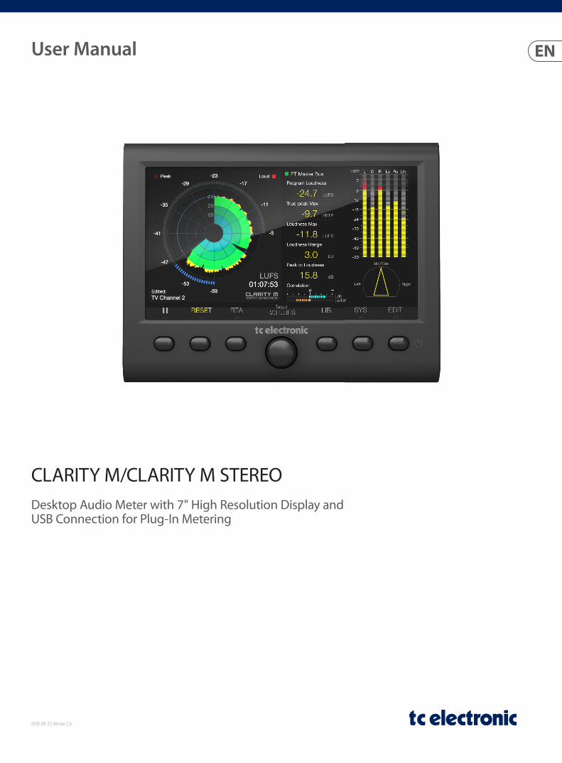
User Manual
CLARITY M/CLARITY M STEREODesktop Audio Meter with 7" High Resolution Display and USB Connection for Plug-In Metering
2018-09-27, Version 2.0
2 CLARITY M/CLARITY M STEREO User Manual
Table of ContentsImportant Safety Instructions ...................................... 3
Legal Disclaimer ............................................................. 3
Limited warranty ............................................................ 3
1. Introduction ............................................................... 4
2. Mounting .................................................................... 4
3. Hook-up ...................................................................... 4
4. Controls and Connectors .......................................... 8
5. SUB-D Cable ............................................................... 9
6. General Operation ..................................................... 9
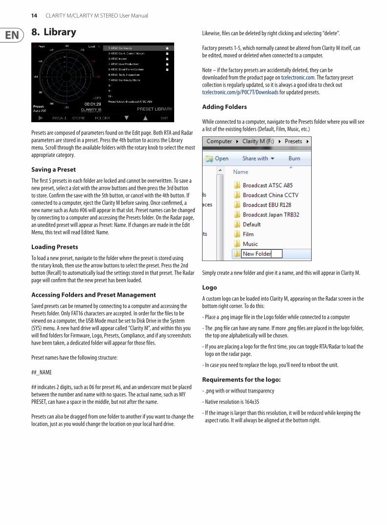
7. Editing Presets ......................................................... 12
8. Library ...................................................................... 14
9. System ...................................................................... 15
10. Plug-in Metering .................................................... 15
11. Firmware Updates .................................................. 18
12. Specifications ......................................................... 19
13. DB15 Cable Pin Assignments ................................ 19
3 CLARITY M/CLARITY M STEREO User Manual
Terminals marked with this symbol carry electrical current of sufficient magnitude to constitute risk of electric shock.
Use only high-quality professional speaker cables with ¼" TS or twist-locking plugs pre-installed. All other installation or modification should be performed only by qualified personnel.
This symbol, wherever it appears, alerts you to the presence of uninsulated dangerous voltage inside the
enclosure - voltage that may be sufficient to constitute a risk of shock.
This symbol, wherever it appears, alerts you to important operating and maintenance instructions in the
accompanying literature. Please read the manual.
CautionTo reduce the risk of electric shock, do not remove the top cover (or the rear section).
No user serviceable parts inside. Refer servicing to qualified personnel.
CautionTo reduce the risk of fire or electric shock, do not expose this appliance to rain and
moisture. The apparatus shall not be exposed to dripping or splashing liquids and no objects filled with liquids, such as vases, shall be placed on the apparatus.
CautionThese service instructions are for use by qualified service personnel only.
To reduce the risk of electric shock do not perform any servicing other than that contained in the operation instructions. Repairs have to be performed by qualified service personnel.
1. Read these instructions.
2. Keep these instructions.
3. Heed all warnings.
4. Follow all instructions.
5. Do not use this apparatus near water.
6. Clean only with dry cloth.
7. Do not block any ventilation openings. Install in accordance with the manufacturer’s instructions.
8. Do not install near any heat sources such as radiators, heat registers, stoves, or other apparatus (including amplifiers) that produce heat.
9. Do not defeat the safety purpose of the polarized or grounding-type plug. A polarized plug has two blades with one wider than the other. A grounding-type plug has two blades and a third grounding prong. The wide blade or the third prong are provided for your safety. If the provided plug does not fit into your outlet, consult an electrician for replacement of the obsolete outlet.
10. Protect the power cord from being walked on or pinched particularly at plugs, convenience receptacles, and the point where they exit from the apparatus.
11. Use only attachments/accessories specified by the manufacturer.
12. Use only with the cart, stand, tripod, bracket, or table specified by the manufacturer, or sold with the apparatus. When a cart is used, use caution when moving the cart/apparatus combination to avoid
injury from tip-over.
13. Unplug this apparatus during lightning storms or when unused for long periods of time.
14. Refer all servicing to qualified service personnel. Servicing is required when the apparatus has been damaged in any way, such as power supply cord or plug is damaged, liquid has been spilled or objects have fallen into the apparatus, the apparatus has been exposed to rain or moisture, does not operate normally, or has been dropped.
15. The apparatus shall be connected to a MAINS socket outlet with a protective earthing connection.
16. Where the MAINS plug or an appliance coupler is used as the disconnect device, the disconnect device shall remain readily operable.
17. Correct disposal of this product: This symbol indicates that this product must not be disposed of with household waste, according to the WEEE Directive (2012/19/EU) and your national law. This product should be taken
to a collection center licensed for the recycling of waste electrical and electronic equipment (EEE). The mishandling of this type of waste could have a possible negative impact on the environment and human health due to potentially hazardous substances that are generally associated with EEE. At the same time, your cooperation in the correct disposal of this product will contribute to the efficient use of natural resources. For more information about where you can take your waste equipment for recycling, please contact your local city office, or your household waste collection service.
18. Do not install in a confined space, such as a book case or similar unit.
19. Do not place naked flame sources, such as lighted candles, on the apparatus.
20. Please keep the environmental aspects of battery disposal in mind. Batteries must be disposed-of at a battery collection point.
21. Use this apparatus in tropical and/or moderate climates.
Music Tribe accepts no liability for any loss which may be suffered by any person who relies either wholly or in part upon any description, photograph, or statement contained herein. Technical specifications, appearances and other information are subject to change without notice. All trademarks are the property of their respective owners. Midas, Klark Teknik, Lab Gruppen, Lake, Tannoy, Turbosound, TC Electronic, TC Helicon, Behringer, Bugera and Coolaudio are trademarks or registered trademarks of Music Tribe Global Brands Ltd. © Music Tribe Global Brands Ltd. 2018 All rights reserved.
For the applicable warranty terms and conditions and additional information regarding Music Tribe’s Limited Warranty, please see complete details online at musictribe.com/warranty.
Zhongshan Eurotec Electronics LimitedNo. 10 Wanmei Road, South China Modern Chinese Medicine Park, Nanlang Town, 528451, Zhongshan City, Guangdong Province, China
Important Safety Instructions
LEGAL DISCLAIMER
LIMITED WARRANTY
4 CLARITY M/CLARITY M STEREO User Manual
1. IntroductionClarity M and Clarity M Stereo
This manual covers two versions: Clarity M and Clarity M Stereo. Clarity M supports stereo and 5.1 via plug-in and AES. Clarity M Stereo supports stereo operation only. Most of the features described in this manual apply to both models, unless otherwise noted in the text.
The Clarity M provides a comprehensive set of precision tools essential to the success of any audio producer. Ideally suited to stereo and 5.1 mixing, mastering and post-production, Clarity M’s 7" high-resolution LCD display provides a wealth of monitoring information at-a-glance via a single screen. Metering options include the legendary LM6 Loudness Radar Meter, a state-of-the-art true peak meter, vector scope meter, downmix compliance, stereo/surround correlation meters and an RTA (Real Time Analyzer).
Source inputs come in a vast array of options including: USB for hassle-free VST*, Audio Units* and AAX* plug-in metering, 6 channels of unbalanced AES3 digital audio on 75 Ohm BNC connectors for broadcast-grade 5.1 metering, and stereo optical for maximum flexibility.
Continue through this manual to learn about the functionality and operation of the Clarity M.
2. MountingThe Clarity M includes a built-in stand that can be installed during use and then reverted back to its storage/travel position. Follow these steps to mount the stand:
• Remove the 2 hex screws that hold the stand flat against the back of the unit. The screws are designed to be operated with a 2.5 mm hex key.
• Flip the stand around so that it sticks outward from the unit. The stand has rubber pads to prevent it from scratching the surface where it is placed.
• Replace the screws into the same holes to secure the stand.
RAM Mount
The Clarity M also has 2 holes that are ready to use with any compatible mount solution. We recommend RAM mounts (www.rammount.com), but others are also available. These allow convenient attachment to desks or walls for easy access and ideal viewing. The M5 screws needed for installation are not included, and vary in length depending on the mounting solution you purchase. Follow the directions for your mounting solution to install.
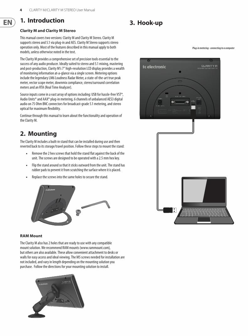
Plug-in metering - connecting to a computer
3. Hook-up
5 CLARITY M/CLARITY M STEREO User Manual
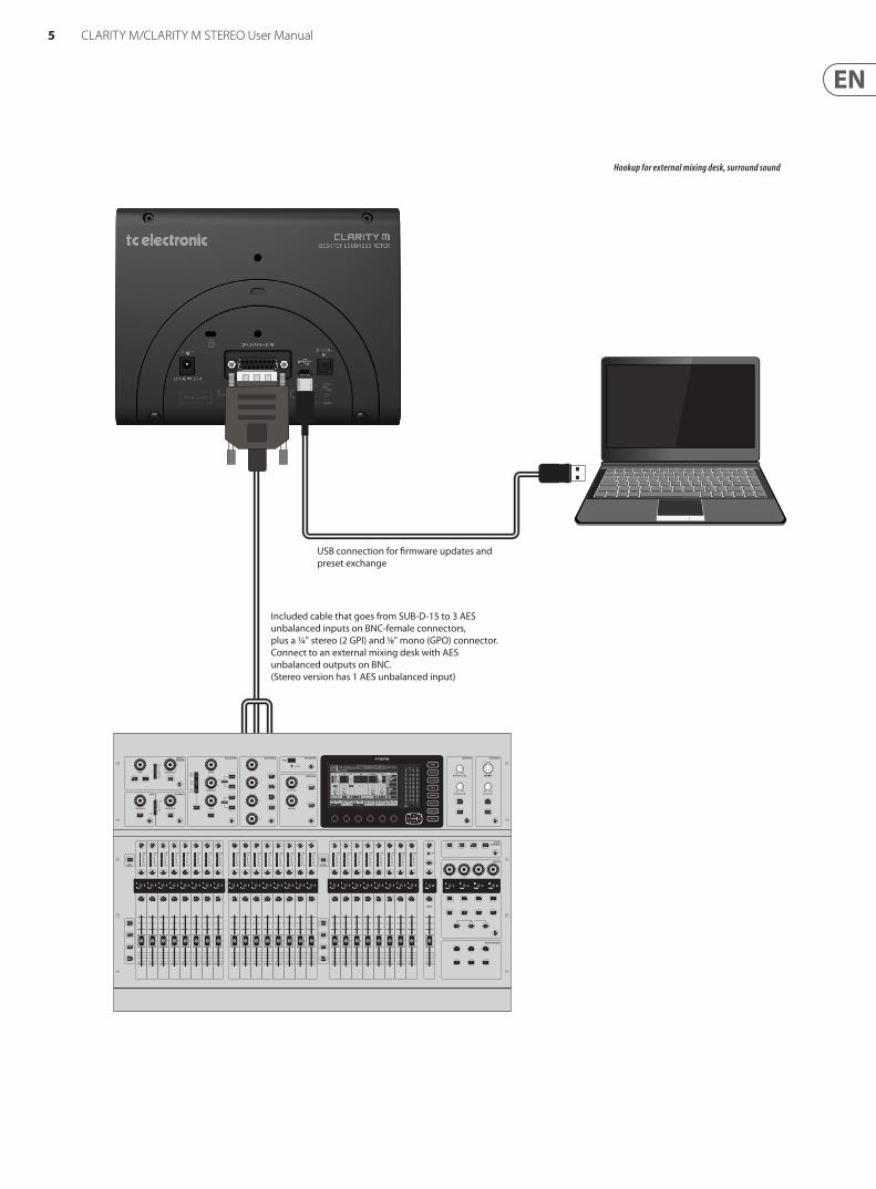
Hookup for external mixing desk, surround sound
USB connection for �rmware updates and preset exchange
Included cable that goes from SUB-D-15 to 3 AES unbalanced inputs on BNC-female connectors, plus a ¼" stereo (2 GPI) and 1⁄8" mono (GPO) connector. Connect to an external mixing desk with AES unbalanced outputs on BNC.(Stereo version has 1 AES unbalanced input)
6 CLARITY M/CLARITY M STEREO User Manual
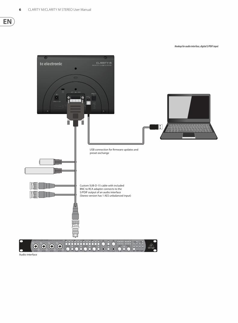
Hookup for audio interface, digital S/PDIF input
USB connection for �rmware updates and preset exchange
Custom SUB-D-15 cable with includedBNC to RCA adapter connects to theS/PDIF output of an audio interface(Stereo version has 1 AES unbalanced input)
Audio interface
7 CLARITY M/CLARITY M STEREO User Manual
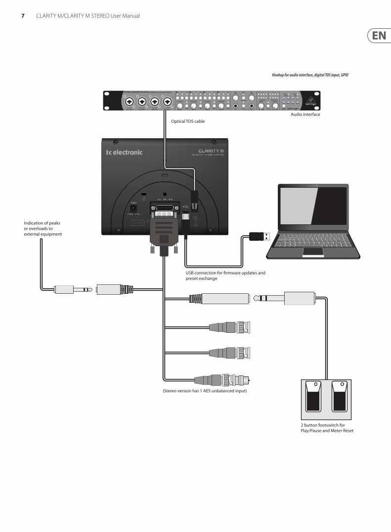
Hookup for audio interface, digital TOS input, GPIO
USB connection for �rmware updates and preset exchange
Indication of peaks or overloads to external equipment
Optical TOS cable
Audio interface
2 button footswitch for Play/Pause and Meter Reset
(Stereo version has 1 AES unbalanced input)
8 CLARITY M/CLARITY M STEREO User Manual
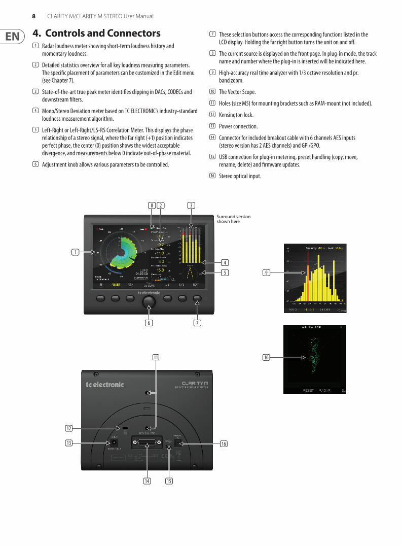
4. Controls and Connectors(1) Radar loudness meter showing short-term loudness history and
momentary loudness.
(2) Detailed statistics overview for all key loudness measuring parameters. The specific placement of parameters can be customized in the Edit menu (see Chapter 7).
(3) State-of-the-art true peak meter identifies clipping in DACs, CODECs and downstream filters.
(4) Mono/Stereo Deviation meter based on TC ELECTRONIC’s industry-standard loudness measurement algorithm.
(5) Left-Right or Left-Right/LS-RS Correlation Meter. This displays the phase relationship of a stereo signal, where the far right (+1) position indicates perfect phase, the center (0) position shows the widest acceptable divergence, and measurements below 0 indicate out-of-phase material.
(6) Adjustment knob allows various parameters to be controlled.
(7) These selection buttons access the corresponding functions listed in the LCD display. Holding the far right button turns the unit on and off.
(8) The current source is displayed on the front page. In plug-in mode, the track name and number where the plug-in is inserted will be indicated here.
(9) High-accuracy real time analyzer with 1/3 octave resolution and pr. band zoom.
(10) The Vector Scope.
(11) Holes (size M5) for mounting brackets such as RAM-mount (not included).
(12) Kensington lock.
(13) Power connection.
(14) Connector for included breakout cable with 6 channels AES inputs (stereo version has 2 AES channels) and GPI/GPO.
(15) USB connection for plug-in metering, preset handling (copy, move, rename, delete) and firmware updates.
(16) Stereo optical input.
(9)
(10)
(4)
(11)
(16)
(12)
(13)
(14) (15)
(1)
(2)
(5)
(3)(8)
(7)(6)
Surround version shown here
9 CLARITY M/CLARITY M STEREO User Manual
5. SUB-D CableA SUB-D-15 breakout cable is included with the Clarity M for connection to external digital audio devices, as well as GPIO connection. 3 BNC connectors accept signals from digital mixing consoles or from an audio interface via S/PDIF by using the included BNC-to-RCA adapter (Stereo version has 1 BNC connector). See Chapter 13 for pin assignment details.
To connect to an AES/EBU-based device, a BNC-to-XLR adapter will be necessary. For surround sound use, 3 adapters will be needed. We recommend the Neutrik NA2FBNC adapter for this purpose. One BNC-to-XLR adapter is included with the Stereo model.
GPIO is connected via a dedicated 1/8" TS output and a stereo 1/4" TRS input. These can be used, for example, to trigger Stop/Play or Measurement RESET commands remotely.
6. General OperationAfter the Clarity M has been mounted, audio connections have been made, and power is supplied, press the 6th button to power the unit on.
Note – to turn the unit off, hold the 6th button for 2 seconds, which brings up the power-off screen. You can either power off completely with the 6th button, reboot with the 5th button, or cancel the request with the 4th button.
Main Section
The main meter graphic on the left side of the screen can be viewed in either LM6 Loudness Radar, RTA (Real Time Analyzer), or Vector Scope, depending on your audio environment. The RTA view is ideal for monitoring short-term results across the full frequency spectrum, while Radar view is great for long-term results. The Vector Scope can help identify important stereo balance and phase issues in your mix. Pressing the 3rd button flips between the 3 types of metering.
Radar
The loudness radar meter is ideal for simultaneously monitoring short-term loudness (S) history on the scope and momentary loudness (M) on the outer ring. The momentary loudness of your signal is based on a sliding 400 ms window, which makes it a valuable aid in setting initial levels when you start a new mix. The short-term loudness overview is especially important to keep an eye on when mixing material on the fly, as it responds quickly when you adjust your mix, making it a helpful indicator of where your loudness is in relation to the target value.
(6)(7)(8)
(1)
(2)
(3) (5)(4)
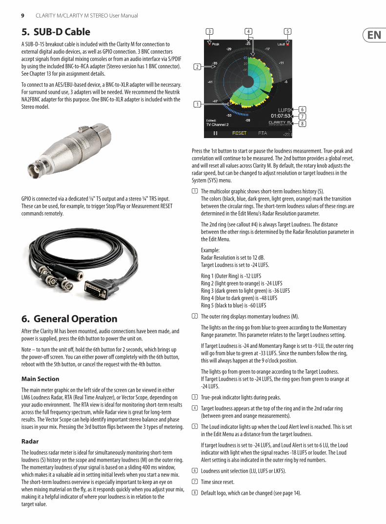
Press the 1st button to start or pause the loudness measurement. True-peak and correlation will continue to be measured. The 2nd button provides a global reset, and will reset all values across Clarity M. By default, the rotary knob adjusts the radar speed, but can be changed to adjust resolution or target loudness in the System (SYS) menu.
(1) The multicolor graphic shows short-term loudness history (S). The colors (black, blue, dark green, light green, orange) mark the transition between the circular rings. The short-term loudness values of these rings are determined in the Edit Menu's Radar Resolution parameter.
The 2nd ring (see callout #4) is always Target Loudness. The distance between the other rings is determined by the Radar Resolution parameter in the Edit Menu.
Example: Radar Resolution is set to 12 dB. Target Loudness is set to -24 LUFS.
Ring 1 (Outer Ring) is -12 LUFS Ring 2 (light green to orange) is -24 LUFS Ring 3 (dark green to light green) is -36 LUFS Ring 4 (blue to dark green) is -48 LUFS Ring 5 (black to blue) is -60 LUFS
(2) The outer ring displays momentary loudness (M).
The lights on the ring go from blue to green according to the Momentary Range parameter. This parameter relates to the Target Loudness setting.
If Target Loudness is -24 and Momentary Range is set to -9 LU, the outer ring will go from blue to green at -33 LUFS. Since the numbers follow the ring, this will always happen at the 9 o’clock position.
The lights go from green to orange according to the Target Loudness. If Target Loudness is set to -24 LUFS, the ring goes from green to orange at -24 LUFS.
(3) True-peak indicator lights during peaks.
(4) Target loudness appears at the top of the ring and in the 2nd radar ring (between green and orange measurements).
(5) The Loud indicator lights up when the Loud Alert level is reached. This is set in the Edit Menu as a distance from the target loudness.
If target loudness is set to -24 LUFS, and Loud Alert is set to 6 LU, the Loud indicator with light when the signal reaches -18 LUFS or louder. The Loud Alert setting is also indicated in the outer ring by red numbers.
(6) Loudness unit selection (LU, LUFS or LKFS).
(7) Time since reset.
(8) Default logo, which can be changed (see page 14).
10 CLARITY M/CLARITY M STEREO User Manual
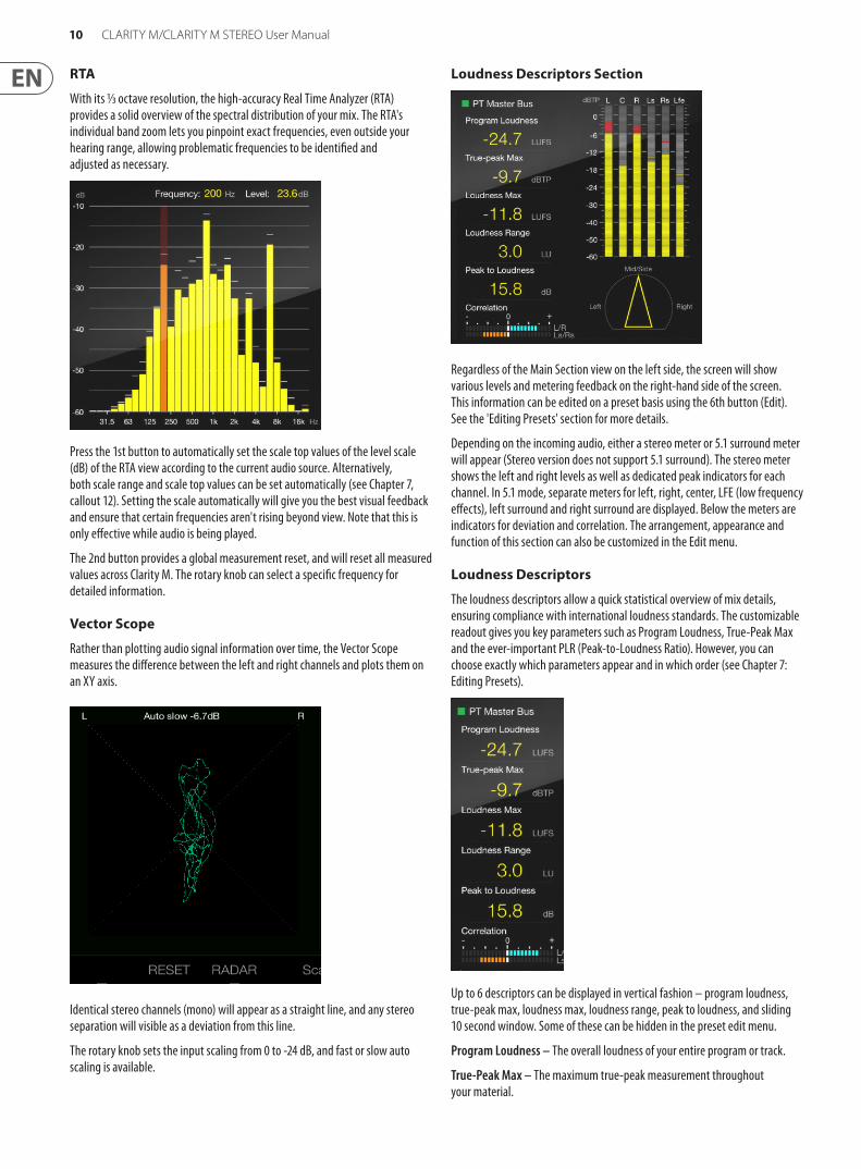
RTA
With its 1/3 octave resolution, the high-accuracy Real Time Analyzer (RTA) provides a solid overview of the spectral distribution of your mix. The RTA's individual band zoom lets you pinpoint exact frequencies, even outside your hearing range, allowing problematic frequencies to be identified and adjusted as necessary.
Press the 1st button to automatically set the scale top values of the level scale (dB) of the RTA view according to the current audio source. Alternatively, both scale range and scale top values can be set automatically (see Chapter 7, callout 12). Setting the scale automatically will give you the best visual feedback and ensure that certain frequencies aren't rising beyond view. Note that this is only effective while audio is being played.
The 2nd button provides a global measurement reset, and will reset all measured values across Clarity M. The rotary knob can select a specific frequency for detailed information.
Vector Scope
Rather than plotting audio signal information over time, the Vector Scope measures the difference between the left and right channels and plots them on an XY axis.
Identical stereo channels (mono) will appear as a straight line, and any stereo separation will visible as a deviation from this line.
The rotary knob sets the input scaling from 0 to -24 dB, and fast or slow auto scaling is available.
Loudness Descriptors Section
Regardless of the Main Section view on the left side, the screen will show various levels and metering feedback on the right-hand side of the screen. This information can be edited on a preset basis using the 6th button (Edit). See the 'Editing Presets' section for more details.
Depending on the incoming audio, either a stereo meter or 5.1 surround meter will appear (Stereo version does not support 5.1 surround). The stereo meter shows the left and right levels as well as dedicated peak indicators for each channel. In 5.1 mode, separate meters for left, right, center, LFE (low frequency effects), left surround and right surround are displayed. Below the meters are indicators for deviation and correlation. The arrangement, appearance and function of this section can also be customized in the Edit menu.
Loudness Descriptors
The loudness descriptors allow a quick statistical overview of mix details, ensuring compliance with international loudness standards. The customizable readout gives you key parameters such as Program Loudness, True-Peak Max and the ever-important PLR (Peak-to-Loudness Ratio). However, you can choose exactly which parameters appear and in which order (see Chapter 7: Editing Presets).
Up to 6 descriptors can be displayed in vertical fashion – program loudness, true-peak max, loudness max, loudness range, peak to loudness, and sliding 10 second window. Some of these can be hidden in the preset edit menu.
Program Loudness – The overall loudness of your entire program or track.
True-Peak Max – The maximum true-peak measurement throughout your material.
11 CLARITY M/CLARITY M STEREO User Manual
Loudness Max – The maximum short-term loudness measurement throughout your material.
Loudness Range – Your overall program material range from the softest point to the loudest.
Peak to Loudness – Indicates the 'squash' factor/ratio of your overall material.
Sliding 10 sec – The maximum loudness measurement within a 10 second window.
Balance-O-Meter
This innovative new meter allows quick visual feedback of the left-right and mid-side balances of your mix. It can be activated by entering the Edit menu and pressing the Layout button, then using the arrow buttons to select a location where you want the Balance-O-Meter to appear. Turn the rotary wheel (Adjust) to select this meter. Note that it will take up 2 slots in the Loudness Descriptors list.
The top of the triangle will point toward the top/center of the semi circle when a perfect left-right balance is achieved. The width is indicated by how broad the base of the triangle is.
A wide, center-balanced mix will appear as a symmetrical triangle.
The top point will tilt either direction as the channels become less balanced, and the base will appear narrower to indicate less width.
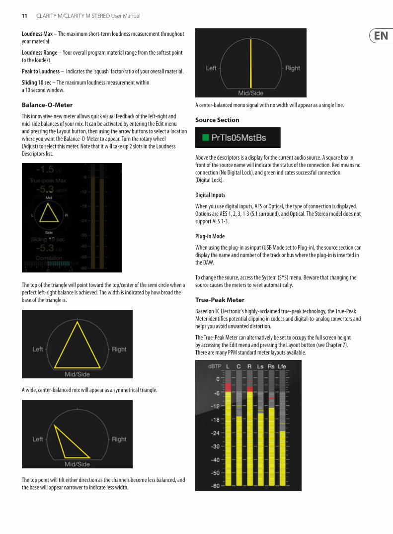
A center-balanced mono signal with no width will appear as a single line.
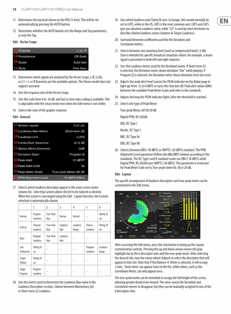
Source Section
Above the descriptors is a display for the current audio source. A square box in front of the source name will indicate the status of the connection. Red means no connection (No Digital Lock), and green indicates successful connection (Digital Lock).
Digital Inputs
When you use digital inputs, AES or Optical, the type of connection is displayed. Options are AES 1, 2, 3, 1-3 (5.1 surround), and Optical. The Stereo model does not support AES 1-3.
Plug-in Mode
When using the plug-in as input (USB Mode set to Plug-in), the source section can display the name and number of the track or bus where the plug-in is inserted in the DAW.
To change the source, access the System (SYS) menu. Beware that changing the source causes the meters to reset automatically.
True-Peak Meter
Based on TC Electronic's highly-acclaimed true-peak technology, the True-Peak Meter identifies potential clipping in codecs and digital-to-analog converters and helps you avoid unwanted distortion.
The True-Peak Meter can alternatively be set to occupy the full screen height by accessing the Edit menu and pressing the Layout button (see Chapter 7). There are many PPM standard meter layouts available.

12 CLARITY M/CLARITY M STEREO User Manual
Because loudness measuring is based on subjective perception, program material can overload if normalized using traditional techniques like quasi-peak or sample-peak. For this reason, normalization has become a part of many broadcast standards that require a true-peak meter. A true-peak meter looks at the actual samples as well as inter sample peaks, unveiling peaks that would otherwise cause distortion.
The meters will appear as stereo or 5.1 true-peak depending on the input selection. Note that the Stereo model does not support 5.1 surround. Several options are available to customize the function and appearance of the meter. See Chapter 7 for details.
Channel Measures
This section has 2 horizontal bar graphs that appear in the lower right corner of the screen. The upper graph shows the downmix deviation meter, and the lower shows correlation.
These meters can also be moved to the loudness descriptors column by accessing the Edit menu and pressing the Layout button (see Chapter 7).
Stereo mixes typically have a very strong mono component. Clarity M simulates mono downmix (from stereo to mono) as a sum of L and R. Therefore, the mono downmix deviation of such mixes tend to be around +3 dB. Being close to +3 dB is therefore not considered a problem at all.
Many users will find that the deviation meter is most useful in surround applications, while the correlation meter is more useful when working with stereo material.
Deviation
Downmix Deviation shows you how the source performs when downmixed. This is essential in ensuring your surround mix also sounds good when played back through stereo speakers. Internally, a behind-the-scenes downmix is prepared and a comparison between the loudness of your source to the downmixed version is displayed in the graph. In Stereo mode, we compare the stereo source to mono (Mono Deviation). In 5.1 mode, we compare the 5.1 source to stereo (Stereo Deviation). The Stereo model does not support 5.1, so it will only display stereo-to-mono deviation.
In the Preset Edit menu, select either Short-term or Program to determine the span (time) used to determine the deviation figure.
Correlation
In Stereo mode, the Correlation meter compares the left and right channels with a single bar graph. In 5.1 mode*1, it compares left/right as well as left surround/right surround with 2 bar graphs.
Phase issues can result in audible loss of low frequencies, unintended alterations to a mix, among many other problems. Readings toward the positive end of the meter indicate proper phase alignment (indicated in blue), and phase problems are shown in orange to the left of the meter.
*The Stereo model does not support surround.
7. Editing PresetsPressing the 6th encoder brings up the preset Edit menu. The list is divided into a meter-specific portion that will correspond to the current meter view (Radar/RTA/V-scope), as well as a list of general parameters that are visible regardless of the meter selection.
The Edit menu also allows the arrangement of descriptors and true-peak meter to be customized, including the Balance-O-Meter.
Edit - Radar
1. Adjusts the speed of the radar from 1 minute to 24 hours.
2. Adjusts the radar resolution (distance between each circle in the radar) from 3 to 12 dB.
3. Adjusts the target loudness from -36 to -6 LUFS or LKFS, depending on the Loudness Unit setting (see #19).
4. Sets the level at which the loud alert engages, or turns this function off. The triggering of the LOUD alert depends on this setting in combination with the Target Loudness. If Target Loudness is set to -24 LUFS and this parameter is set to 6 LU, the LOUD alert will be triggered when the sound reaches -18 LUFS.
5. Sets the "zoom" scale on the momentary ring on the radar by setting the distance between Target Loudness and the highest value to be displayed on the Momentary ring. Toggles between +9 LU and +18 LU. If Target Loudness is set to -24 LUFS and Momentary Range is set to +18 LU, the highest value (3 o’clock position on the ring) shown on the momentary ring is 6 LUFS.
Edit - RTA
6. Selects the channels displayed in the RTA. Options are L, R, L+R for stereo mode, plus L+R+C, C, Ls, Rs, Ls+Rs, LFE, and ALL for surround mode*.
7. Selects between 10-band or 31-band RTA resolution.
8. Adjusts the RTA response time:
Slow - shows a 1 second response, providing a more stabilized and averaged response for use with highly dynamic audio.
Fast - 125 ms response for monitoring fairly constant audio.
Impulse - asymmetrical averaging, responding very quickly (35 ms) to increasing audio, and a slow decay of 1.5 seconds for decreasing audio.
9. Adjusts how long the small peak indicator dashes for each band hold their position.
10. Determines the level range of the RTA (Y-Axis), adjustable from 10 to 60 dB. This can set automatically by pressing the AUTO button, depending on the Auto Scale setting (see item #12).
13 CLARITY M/CLARITY M STEREO User Manual
11. Determines the top level shown on the RTA (Y-Axis). This will be set automatically by pressing the AUTO button.
12. Determines whether the AUTO button sets the Range and Top parameters, or only the Top.
Edit - Vector Scope
13. Determines which signals are analyzed by the Vector Scope. L/R, Ls/Rs, or 5.1 > L vs R Downmix are the available options. The Stereo model does not support surround.
14. Sets the response rate of the Vector Scope.
15. Sets the scale from 0 to -24 dB, and fast or slow auto scaling is available. This is adjustable with the rotary knob even when the Edit menu is not visible.
16. Selects the color of the graphic response.
Edit - General
17. Selects which loudness descriptor appear in the main screen center column list. Selecting Custom allows the list to be tailored as desired. When the screen is rearranged using the Edit - Layout function, the Custom selection is automatically chosen.
1 2 3 4 5 6
NormalProgram Loudness
True-Peak Max
Normal Normal --Sliding 10 sec
Full ListProgram Loudness
True-Peak Max
Loudness Max
Loudness Range
Peak to Loudness
Sliding 10 sec
BasicProgram Loudness
True-Peak Max
Loudness Max
-- -- --
Live Production
Sliding 10 sec
-- -- --Program Loudness
Loudness Range
Single Sliding
Sliding 10 sec
-- -- -- -- --
Single Program
Program Loudness
-- -- -- -- --
18. Sets the metric used to determine the Loudness Max value in the Loudness Descriptors section. Choose between Momentary (m) or Short-term (s) Loudness.
19. Sets which loudness unit Clarity M uses. In Europe, this would normally be set to LUFS, while in the US, LKFS is the most common unit. LKFS and LUFS give you absolute Loudness value, while “LU” is used by most territories to describe relative loudness values (relative to Target Loudness).
20. Surround Downmix coefficients used for the Deviation and Correlation meters.
21. Selects between raw summing level (sum) or compensated level (-3 dB). Sum is intended for specific broadcast situations where, for example, a mono signal is presented in both left and right channels.
22. Sets the Loudness metric used for the Deviation meter. If Short-term (S) is selected, the Deviation meter shows deviation “live” while playing. If Program (I) is selected, the Deviation meter shows deviation since last reset.
23. Adjusts the peak alert level (causes the PEAK indicator on the Radar page to light up) from -12 to 0 dBTP, or turns this function off. Peak alert values differ between the available Peak Meter Scales and refer to the standards.
24. Adjusts the long the PEAK indicator lights after the threshold is reached.
25. Selects the type of Peak Meter:
True-peak Meter, 60/30/20 dB
Digital PPM, IEC 60268
DIN, IEC Type I
Nordic, IEC Type I
BBC, IEC Type IIa
EBU, IEC Type IIb
26. Selects between EBU (-18 dBFS) or SMPTE (-20 dBFS) standard. The PPM Alignment Level parameter defines the dBu/dBFS relation according to the standards. The IEC Type I and II standard scales use EBU (-18 dBFS) while Digital PPM, IEC 60268 uses SMPTE (-20 dBFS). This parameter is irrelevant for Peak Meter Scale set to True-peak meter 60, 30 or 20 dB.
Edit - Layout
The specific arrangement of loudness descriptors and true-peak meter can be customized in the Edit menu.
After accessing the Edit menu, press the 2nd button to bring up the Layout customization controls. Pressing the up and down arrows moves the gray highlight bar to the 6 descriptor slots and the true-peak meter. After selecting the desired slot, turn the rotary wheel (Adjust) to select the descriptor that will appear in that slot. Note that if the Balance-O-Meter is selected, it will occupy 2 slots. Some items can appear twice in the list, while others, such as the Correlation Meter, can only appear once.
The true-peak meter can be extended to occupy the full height of the screen, allowing greater detail to be viewed. This view causes the Deviation and Correlation meters to disappear, but they can be manually assigned to one of the 6 descriptor slots.
14 CLARITY M/CLARITY M STEREO User Manual
8. Library
Presets are composed of parameters found on the Edit page. Both RTA and Radar parameters are stored in a preset. Press the 4th button to access the Library menu. Scroll through the available folders with the rotary knob to select the most appropriate category.
Saving a Preset
The first 5 presets in each folder are locked and cannot be overwritten. To save a new preset, select a slot with the arrow buttons and then press the 3rd button to store. Confirm the save with the 5th button, or cancel with the 4th button. If connected to a computer, eject the Clarity M before saving. Once confirmed, a new name such as Auto #06 will appear in that slot. Preset names can be changed by connecting to a computer and accessing the Presets folder. On the Radar page, an unedited preset will appear as Preset: Name. If changes are made in the Edit Menu, this text will read Edited: Name.
Loading Presets
To load a new preset, navigate to the folder where the preset is stored using the rotary knob, then use the arrow buttons to select the preset. Press the 2nd button (Recall) to automatically load the settings stored in that preset. The Radar page will confirm that the new preset has been loaded.
Accessing Folders and Preset Management
Saved presets can be renamed by connecting to a computer and accessing the Presets folder. Only FAT16 characters are accepted. In order for the files to be viewed on a computer, the USB Mode must be set to Disk Drive in the System (SYS) menu. A new hard drive will appear called “Clarity M”, and within this you will find folders for Firmware, Logo, Presets, Compliance, and if any screenshots have been taken, a dedicated folder will appear for those files.
Preset names have the following structure:
##_NAME
## indicates 2 digits, such as 06 for preset #6, and an underscore must be placed between the number and name with no spaces. The actual name, such as MY PRESET, can have a space in the middle, but not after the name.
Presets can also be dragged from one folder to another if you want to change the location, just as you would change the location on your local hard drive.
Likewise, files can be deleted by right clicking and selecting “delete”.
Factory presets 1-5, which normally cannot be altered from Clarity M itself, can be edited, moved or deleted when connected to a computer.
Note – if the factory presets are accidentally deleted, they can be downloaded from the product page on tcelectronic.com. The factory preset collection is regularly updated, so it is always a good idea to check out tcelectronic.com/p/P0C7T/Downloads for updated presets.
Adding Folders
While connected to a computer, navigate to the Presets folder where you will see a list of the existing folders (Default, Film, Music, etc.)
Simply create a new folder and give it a name, and this will appear in Clarity M.
Logo
A custom logo can be loaded into Clarity M, appearing on the Radar screen in the bottom right corner. To do this:
- Place a .png image file in the Logo folder while connected to a computer
- The .png file can have any name. If more .png files are placed in the logo folder, the top one alphabetically will be chosen.
- If you are placing a logo for the first time, you can toggle RTA/Radar to load the logo on the radar page.
- In case you need to replace the logo, you'll need to reboot the unit.
Requirements for the logo:
- .png with or without transparency
- Native resolution is 164x35
- If the image is larger than this resolution, it will be reduced while keeping the aspect ratio. It will always be aligned at the bottom right.
15 CLARITY M/CLARITY M STEREO User Manual
Screenshots
Press buttons 1 and 3 simultaneously to create a screenshot. A prompt will allow you to cancel or confirm the screenshot. If you are connected to a computer, eject Clarity M before confirming. The image will appear in the Screenshots folder when connected to a computer.
9. SystemPress the 5th button to access the System menu. This allows several global adjustments and preferences to be set.
1. When the Clarity M is connected to a computer via USB, it can operate in two modes (USB Modes):
Disk Drive Mode Use this setting to:
- Organize presets: Rename, copy, delete or move - Add your company's logo to the front screen of Clarity M - Transfer screenshots from Clarity M to your computer’s hard drive - Update firmware
Plug-in Mode Use Plug-in Mode if you want to use the Clarity M plug-in as a sound source for the Clarity M meter.
When switching from Disk Drive mode to Plug-in Mode, Clarity M will no longer be a USB drive, and to prevent data loss you will be prompted to use the eject feature of your computer to eject the Clarity M USB Drive from your computer.
2. Select the input source. When using digital inputs, AES or optical, the options are AES 1, 2, 3, 1-3 (5.1 surround*2), and optical. When USB Mode is set to Plug-in, the input will automatically be changed to Plug-in. Note that changing the input causes the meters to reset.
3. In case you work in surround, this parameter determines in which order the channels are displayed. This parameter has no effect on the routing of the channels; the audio channel routing of Clarity M is fixed to the ITU routing matrix (L-R-C-LFE-LS-RS). It affects only the order the channels are displayed. The options are:
Film: L-C-R-LS-RS-LFE ITU: L-R-C-LFE-LS-RS This feature does not apply to the Stereo model.
4. Select the function of the rotary knob when using the radar meter.
*The Stereo model does not support surround.
5. Select the function of GPI 1 and 2. Each can trigger pause or reset commands from a remote device.
6. Select the function of the GPO. This can send either the Peak, Loud, or 'Peak or Loud' indications to an external device. See Chapter 6 - Radar section for details.
7. Adjust the LCD brightness.
8. Adjust the LCD contract.
9. Scroll through a list of system information.
10. View the relevant FCC and CE compliance information by scrolling with the rotary knob.
10. Plug-in MeteringDownload the Clarity M plug-in installer from tcelectronic.com/p/P0C7T/Downloads.
Installation on a Mac
Open the zip folder and double click the installer icon.
Proceed through the prompts, accept the license agreement and begin installation.
Installation on PC
Open the zip folder and double click the executable file.
16 CLARITY M/CLARITY M STEREO User Manual
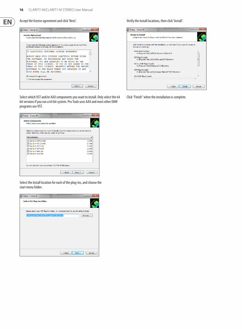
Accept the license agreement and click 'Next'.
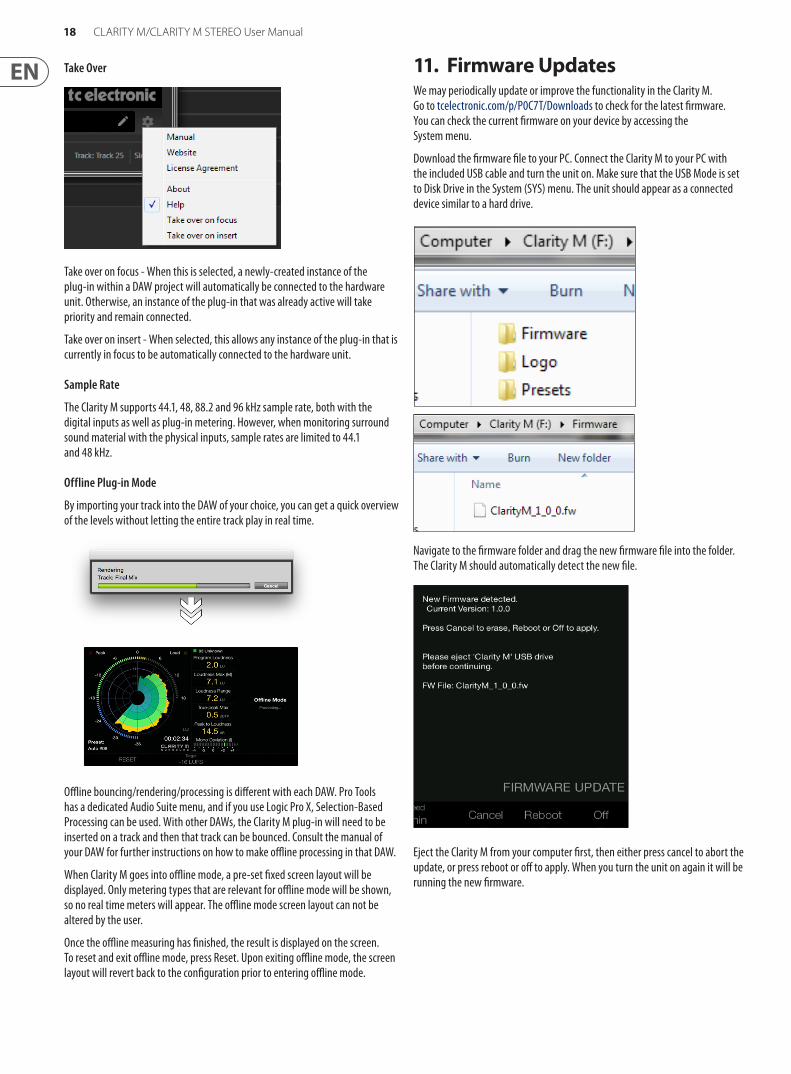
Select which VST and/or AAX components you want to install. Only select the 64 bit versions if you run a 64 bit system. Pro Tools uses AAX and most other DAW programs use VST.
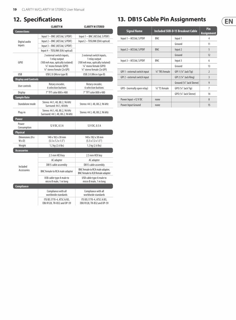
Select the install location for each of the plug-ins, and choose the start menu folder.
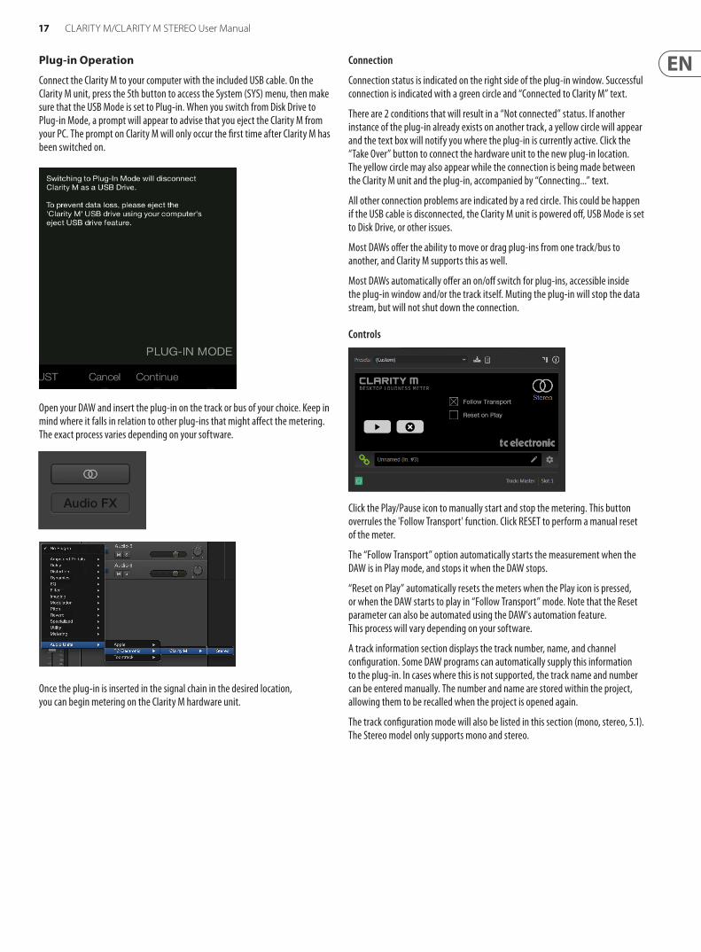
Verify the install locations, then click 'Install'.
Click “Finish” when the installation is complete.
17 CLARITY M/CLARITY M STEREO User Manual
Plug-in Operation
Connect the Clarity M to your computer with the included USB cable. On the Clarity M unit, press the 5th button to access the System (SYS) menu, then make sure that the USB Mode is set to Plug-in. When you switch from Disk Drive to Plug-in Mode, a prompt will appear to advise that you eject the Clarity M from your PC. The prompt on Clarity M will only occur the first time after Clarity M has been switched on.
Open your DAW and insert the plug-in on the track or bus of your choice. Keep in mind where it falls in relation to other plug-ins that might affect the metering. The exact process varies depending on your software.
Once the plug-in is inserted in the signal chain in the desired location, you can begin metering on the Clarity M hardware unit.
Connection
Connection status is indicated on the right side of the plug-in window. Successful connection is indicated with a green circle and “Connected to Clarity M” text.
There are 2 conditions that will result in a “Not connected” status. If another instance of the plug-in already exists on another track, a yellow circle will appear and the text box will notify you where the plug-in is currently active. Click the “Take Over” button to connect the hardware unit to the new plug-in location. The yellow circle may also appear while the connection is being made between the Clarity M unit and the plug-in, accompanied by “Connecting...” text.
All other connection problems are indicated by a red circle. This could be happen if the USB cable is disconnected, the Clarity M unit is powered off, USB Mode is set to Disk Drive, or other issues.
Most DAWs offer the ability to move or drag plug-ins from one track/bus to another, and Clarity M supports this as well.
Most DAWs automatically offer an on/off switch for plug-ins, accessible inside the plug-in window and/or the track itself. Muting the plug-in will stop the data stream, but will not shut down the connection.
Controls
Click the Play/Pause icon to manually start and stop the metering. This button overrules the 'Follow Transport' function. Click RESET to perform a manual reset of the meter.
The “Follow Transport” option automatically starts the measurement when the DAW is in Play mode, and stops it when the DAW stops.
“Reset on Play” automatically resets the meters when the Play icon is pressed, or when the DAW starts to play in “Follow Transport” mode. Note that the Reset parameter can also be automated using the DAW's automation feature. This process will vary depending on your software.
A track information section displays the track number, name, and channel configuration. Some DAW programs can automatically supply this information to the plug-in. In cases where this is not supported, the track name and number can be entered manually. The number and name are stored within the project, allowing them to be recalled when the project is opened again.
The track configuration mode will also be listed in this section (mono, stereo, 5.1). The Stereo model only supports mono and stereo.
18 CLARITY M/CLARITY M STEREO User Manual
Take Over
Take over on focus - When this is selected, a newly-created instance of the plug-in within a DAW project will automatically be connected to the hardware unit. Otherwise, an instance of the plug-in that was already active will take priority and remain connected.
Take over on insert - When selected, this allows any instance of the plug-in that is currently in focus to be automatically connected to the hardware unit.
Sample Rate
The Clarity M supports 44.1, 48, 88.2 and 96 kHz sample rate, both with the digital inputs as well as plug-in metering. However, when monitoring surround sound material with the physical inputs, sample rates are limited to 44.1 and 48 kHz.
Offline Plug-in Mode
By importing your track into the DAW of your choice, you can get a quick overview of the levels without letting the entire track play in real time.
Offline bouncing/rendering/processing is different with each DAW. Pro Tools has a dedicated Audio Suite menu, and if you use Logic Pro X, Selection-Based Processing can be used. With other DAWs, the Clarity M plug-in will need to be inserted on a track and then that track can be bounced. Consult the manual of your DAW for further instructions on how to make offline processing in that DAW.
When Clarity M goes into offline mode, a pre-set fixed screen layout will be displayed. Only metering types that are relevant for offline mode will be shown, so no real time meters will appear. The offline mode screen layout can not be altered by the user.
Once the offline measuring has finished, the result is displayed on the screen. To reset and exit offline mode, press Reset. Upon exiting offline mode, the screen layout will revert back to the configuration prior to entering offline mode.
11. Firmware UpdatesWe may periodically update or improve the functionality in the Clarity M. Go to tcelectronic.com/p/P0C7T/Downloads to check for the latest firmware. You can check the current firmware on your device by accessing the System menu.
Download the firmware file to your PC. Connect the Clarity M to your PC with the included USB cable and turn the unit on. Make sure that the USB Mode is set to Disk Drive in the System (SYS) menu. The unit should appear as a connected device similar to a hard drive.
Navigate to the firmware folder and drag the new firmware file into the folder. The Clarity M should automatically detect the new file.
Eject the Clarity M from your computer first, then either press cancel to abort the update, or press reboot or off to apply. When you turn the unit on again it will be running the new firmware.
19 CLARITY M/CLARITY M STEREO User Manual
12. SpecificationsCLARITY M CLARITY M STEREO
Connections
Digital audio inputs
Input 1 – BNC (AES3id, S/PDIF) Input 1 – BNC (AES3id, S/PDIF)
Input 2 – BNC (AES3id, S/PDIF) Input 2 – TOSLINK (EIAJ optical)
Input 3 – BNC (AES3id, S/PDIF)
Input 4 – TOSLINK (EIAJ optical)
GPIO
2 external switch inputs, 1 relay output
(100 mA max, optically isolated)1/8" mono female (GPO)
1/4" stereo female (2x GPI)
2 external switch inputs, 1 relay output
(100 mA max, optically isolated)1/8" mono female (GPO)
1/4" stereo female (2x GPI)
USB USB 2.0 (Micro type B) USB 2.0 (Micro type B)
Display and Controls
User controls Rotary encoder, 6 selection buttons
Rotary encoder, 6 selection buttons
Display 7" TFT color 800 x 480 7" TFT color 800 x 480
Sample Rate
Standalone mode Stereo: 44.1, 48, 88.2, 96 kHzSurround: 44.1, 48 kHz Stereo: 44.1, 48, 88.2, 96 kHz
Plug-in Stereo: 44.1, 48, 88.2, 96 kHzSurround: 44.1, 48, 88.2, 96 kHz Stereo: 44.1, 48, 88.2, 96 kHz
Power
Power Consumption 12 V DC, 0.5 A 12 V DC, 0.5 A
Physical
Dimensions (H x W x D)
140 x 182 x 38 mm (5.5 x 7.2 x 1.5")
140 x 182 x 38 mm (5.5 x 7.2 x 1.5")
Weight 1.2 kg (2.6 lbs) 1.2 kg (2.6 lbs)
Accessories
Included Accessories
2.5 mm HEX key 2.5 mm HEX key
AC adapter AC adapter
DB15 cable assembly DB15 cable assembly
BNC female to RCA male adapter BNC female to RCA male adapter,BNC female to XLR female adapter
USB cable type A male to micro B male, 1 m long
USB cable type A male to micro B male, 1 m long
Compliance
Compliance with all worldwide standards
Compliance with all worldwide standards
ITU BS.1770-4, ATSC A/85, EBU R128, TR-B32 and OP-59
ITU BS.1770-4, ATSC A/85, EBU R128, TR-B32 and OP-59
13. DB15 Cable Pin Assignments
Signal Name Included SUB-D-15 Breakout Cable Pin Assignment
Input 1 – AES3id, S/PDIF BNC Input 1 4
Ground 11
Input 2 – AES3id, S/PDIF BNC Input 2 5
Ground 12
Input 3 – AES3id, S/PDIF BNC Input 3 6
Ground 13
GPI 1 - external switch input 1/4" TRS female GPI 1 (1/4" Jack Tip) 2
GPI 2 - external switch input GPI 2 (1/4" Jack Ring) 3
Ground (1/4" Jack Sleeve) 9
GPO - (normally open relay) 1/8" TS female GPO (1/8" Jack Tip) 7
GPO (1/8" Jack Sleeve) 14
Power Input +12 V DC none 8
Power Input Ground none 15