Clanging Pipes and Open Windows: Upgrading NYC Steam ...
24
UPGRADING NYC STEAM SYSTEMS FOR THE 21ST CENTURY CLANGING PIPES AND OPEN WINDOWS:
Transcript of Clanging Pipes and Open Windows: Upgrading NYC Steam ...

UPGRADING NYC STEAM SYSTEMS FOR THE 21ST CENTURY
CLANGING PIPES AND OPEN WINDOWS:
ACKNOWLEDGMENTS
This report was created as part of the Energy Efficiency for All Project (EEFA); a joint effort of the Natural Resources Defense Council (NRDC), the National Housing Trust, the Energy Foundation, and Elevate Energy. The mission of EEFA is to make multifamily homes healthier and more affordable through energy and water efficiency and access to clean energy, benefitting millions of Americans living on limited incomes. The project brings together the energy and housing sectors in 12 states, providing tools and resources to help create efficiency, health, and clean energy opportunities for low-income residents, while helping states and utilities achieve efficiency goals and reduce power plant pollution. EEFA is made possible by funding from the JPB Foundation.
This report was authored by Steven Winter Associates (SWA), including Jason Block, Nicole Ceci, Jonathan Flothow, Heather Nolen and Marc Zuluaga. Jonathan Flothow is the primary author of this report and has dedicated his career to understanding and improving steam heating systems. The report’s content is based in large part on the work SWA’s Multifamily Energy Services team has done analyzing steam heating systems in NYC.
In the course of preparing and shaping the content of this report, we benefited from and appreciate the valuable input of the Urban Green Council who reviewed the report and provided guidance, the New York City Mayor’s Office of Sustainability who provided guidance and access to crucial LL87 data, and Henry Gifford who reviewed the report, provided guidance and was the first person to rediscover orifice plates and use them to eliminate the need for steam traps. We also thank Laurie Kerr and Raya Salter who were instrumental in the development of the report while at NRDC, Lindsay Robbins who proved crucial in its completion, and Tanja Bos, Linda Corman, and Debby Warren for their skilled help producing this report. We would also like to thank Dan Holohan for contributing immensely to the compilation and dissemination of the knowledge required to make steam systems work.

1 CLANGING PIPES AND OPEN WINDOWS: UPGRADING NYC STEAM SYSTEMS FOR THE 21ST CENTURY
Table of Contents ..................................................................................................................................................... 1
Executive Summary .................................................................................................................................................. 2
Introduction .............................................................................................................................................................. 4
System Evaluations and Upgrades ........................................................................................................................... 6
Requirements for Boilers and Burners ........................................................................................................ 6
Multi-sensor Heat Controls .......................................................................................................................... 6
Master Venting ............................................................................................................................................ 7
Two-Pipe Steam System Balancing and Control .......................................................................................... 8
One-Pipe Steam System Control ................................................................................................................. 9
Steam Quality ............................................................................................................................................ 10
Design and Oversight ............................................................................................................................................. 12
The Case for Steam Upgrades ............................................................................................................................... 13
Conclusion .............................................................................................................................................................. 14
Appendix A: Boiler Sizing ........................................................................................................................................ 15
Appendix B: Burner Modulation ............................................................................................................................. 16
Appendix C: Two-Pipe Steam with Orifice Plates ................................................................................................... 18
Appendix D: Emerging Technologies ...................................................................................................................... 20
Appendix E: Hydronic Conversion .......................................................................................................................... 21
References ............................................................................................................................................................. 21
TABLE OF CONTENTS
2 CLANGING PIPES AND OPEN WINDOWS: UPGRADING NYC STEAM SYSTEMS FOR THE 21ST CENTURY
Steam heating systems, particularly those in multifamily buildings,
are responsible for a significant slice of New York City’s carbon
emissions. Upgrading these systems represents a smart strategy to
meet environmental goals, save building owners money, and provide greater
comfort to apartment residents. The opportunity is clear for multifamily
building owners, the building industry, and the city to partner together to bring
NYC’s steam heating systems into the 21st century.
EXECUTIVE SUMMARY
This report highlights best practices to make steam heating systems in NYC’s multifamily stock significantly more energy efficient, thus reducing this important building sector’s oil and gas usage. The bottom line is that no single measure can maximize a steam system’s efficiency – a comprehensive approach must be taken. And the gains are significant. If we appropriately repair and upgrade steam heating systems in larger multifamily buildings, owners could save $147 million annually in heating and maintenance bills. In addition, 312,000 tons of carbon emissions could be avoided.
A DINOSAUR IN THE BASEMENT. Our steam heating systems were designed for that distant era when we burned coal to power our boilers. While coal has long been replaced by oil and natural gas, most of NYC’s heating systems were never appropriately modified because energy was cheap at the time of transition. Although energy costs are no longer low, few stakeholders in the multifamily building sector are cognizant of the potential benefits from repairing and
2 EVALUATING STEAM RETROFIT STRATEGIES IN NYC
upgrading steam heating systems. Nor do they have a roadmap for how to proceed.
This report explains the design and operation of steam systems, the causes of their inefficiencies and shortcomings, and technical strategies for addressing these issues. We describe a comprehensive approach that can be applied to any steam-heated building to optimize cost, comfort, and carbon performance. Though not complex, these solutions do require attention to detail, communications with residents, and buy-in from maintenance staff.
RECOMMENDATIONS. The report’s recommendations focus on the following changes in equipment, installation, and maintenance of steam heating systems in multifamily buildings:
n Orifice Plates. Almost all two-pipe steam systems (typically found in buildings more than six stories high) use radiator traps that typically fail after a few years, resulting in underheating in some apartments and overheating everywhere else. The solution? Equip each radiator with an orifice plate, a small metal plate about the size and shape of a bottle cap. These plates obviate the need for most radiator steam traps, never wear out, and help balance the steam system throughout the building.
n Multi-sensor Thermostatic Heat Controls. Traditional steam heat controls do not monitor apartment temperature. Rather, they respond to external temperatures -- the colder it gets outside, the longer the boiler runs, resulting in overheating and uncomfortable residents. The solution? Replace with smart, multi-sensor heat controls that monitor inside temperatures.
3 CLANGING PIPES AND OPEN WINDOWS: UPGRADING NYC STEAM SYSTEMS FOR THE 21ST CENTURY
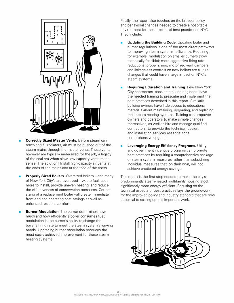
n Correctly Sized Master Vents. Before steam can reach and fill radiators, air must be pushed out of the steam mains through the master vents. These vents however are typically undersized for the job, a legacy of the coal era when slow, low-capacity vents made sense. The solution? Install high-capacity air vents at the ends of the mains and at the tops of the risers.
n Properly Sized Boilers. Oversized boilers – and many of New York City’s are oversized – waste fuel, cost more to install, provide uneven heating, and reduce the effectiveness of conservation measures. Correct sizing of a replacement boiler will create immediate front-end and operating cost savings as well as enhanced resident comfort.
n Burner Modulation. The burner determines how much and how efficiently a boiler consumes fuel; modulation is the burner’s ability to change the boiler’s firing rate to meet the steam system’s varying needs. Upgrading burner modulation produces the most easily achieved improvement for these steam heating systems.
Finally, the report also touches on the broader policy and behavioral changes needed to create a hospitable environment for these technical best practices in NYC. They include:
n Updating the Building Code. Updating boiler and burner regulations is one of the most direct pathways to improving steam systems’ efficiency. Requiring, for example, modulation on smaller burners (now technically feasible); more aggressive firing-rate reductions; proper sizing, motorized vent dampers, and linkageless controls on new boilers are all rule changes that could have a large impact on NYC’s steam systems.
n Requiring Education and Training. Few New York City contractors, consultants, and engineers have the needed training to prescribe and implement the best practices described in this report. Similarly, building owners have little access to educational materials about maintaining, upgrading, and replacing their steam heating systems. Training can empower owners and operators to make simple changes themselves, as well as hire and manage qualified contractors, to provide the technical, design, and installation services essential for a comprehensive upgrade.
n Leveraging Energy Efficiency Programs. Utility and government incentive programs can promote best practices by requiring a comprehensive package of steam system measures rather than subsidizing individual measures that, on their own, will not achieve predicted energy savings.
This report is the first step needed to make the city’s predominantly steam-heated multifamily housing stock significantly more energy efficient. Focusing on the technical aspects of best practices lays the groundwork for the improved policy and industry standard that are now essential to scaling up this important work.

4 CLANGING PIPES AND OPEN WINDOWS: UPGRADING NYC STEAM SYSTEMS FOR THE 21ST CENTURY
Figure 1: Greenhouse Gas Emissions in NYC Properties over 50,000 Sq. Ft.
INTRODUCTION
Multifamily housing is the largest building sector in New York City,
comprising 64 percent of square footage in buildings above 50,000
square feet. Heating is the largest energy end use in this sector,
causing the vast majority of carbon emissions.1 Approximately 76 percent of
this square footage is heated by steam.2 Most of this steam is generated on
site by boilers that burn fuel and some is provided by the Con Edison district
steam grid.
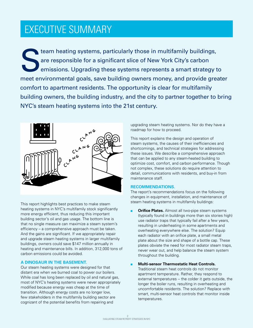
Much of this heat is wasted through building overheating. Based on building inspection data, apartment temperatures are often above 80 degrees Fahrenheit, with residents complaining of excessive heat and opening their windows. These systems also function poorly, with clanging pipes, no resident control, and simultaneous cold and hot apartments. The upgrades that ameliorate these problems improve resident comfort while reducing owner operating costs.
As an example, a 1,000 unit co-op in Brooklyn completed a comprehensive steam system upgrade, resulting in a 30 percent heating fuel use reduction. Resident comfort increased due to having control over their heat, which was balanced throughout the building. The property benefited
LargeMultifamilyBuildings
54%
OtherLarge
Buildings46%
All OtherEnergyUses55%
Space Heating
45% Steam Distribution
80%
OtherHeating
Distribution20%
Greenhouse Gas Emissionsfrom NYC Multifamily Heating
by Distribution Type
Greenhouse Gas Emissionsfrom NYC Multifamily Buildings
by End Use
NYC GreenhouseGas Emissions by Sector
Note: Multifamily buildings refers to those over 50,000 sq. ft. Sources: 2014 NYC Local Law 84 Benchmarking Report and 2013 LL87 data.
from reduced maintenance costs. Savings on this scale are not uncommon. Scaling up this type of work has the potential to reduce citywide carbon emissions by nearly 312,000 tons per year and save $147 million in fuel and maintenance annually. This constitutes a cost-effective solution that can improve New Yorkers’ quality of life while contributing to the aggressive carbon reduction goals outlined in the One City Built to Last plan.3 This plan sets a target of reducing building greenhouse gas emissions by nearly 3.4 million tons annually by 2025. The savings projections from comprehensive steam upgrades described here for multifamily buildings over 50,000 square feet alone are equivalent to achieving 9 percent of this ambitious goal.
4 EVALUATING STEAM RETROFIT STRATEGIES IN NYC
$147M OF POTENTIAL SAVINGS
312,000 TONS OF CARBON PER YEAR
1,2 Based on Local Law 87 data, analyzed as part of this study. 3The One City Built to Last plan was released in 2014.
5 CLANGING PIPES AND OPEN WINDOWS: UPGRADING NYC STEAM SYSTEMS FOR THE 21ST CENTURY
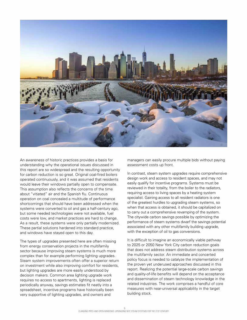
An awareness of historic practices provides a basis for understanding why the operational issues discussed in this report are so widespread and the resulting opportunity for carbon reduction is so great. Original coal-fired boilers operated continuously, and it was assumed that residents would leave their windows partially open to compensate. This assumption also reflects the concerns of the time about “vitiated” air and the Spanish flu. Continuous operation on coal concealed a multitude of performance shortcomings that should have been addressed when the systems were converted to oil and gas a half-century ago, but some needed technologies were not available, fuel costs were low, and market practices are hard to change. As a result, these systems were only partially modernized. These partial solutions hardened into standard practice, and windows have stayed open to this day.
The types of upgrades presented here are often missing from energy conservation projects in the multifamily sector because improving steam systems is much more complex than for example performing lighting upgrades. Steam system improvements often offer a superior return on investment while also improving comfort for residents, but lighting upgrades are more easily understood by decision makers. Common area lighting upgrade work requires no access to apartments, lighting is replaced periodically anyway, savings estimates fit neatly into a spreadsheet, incentive programs have historically been very supportive of lighting upgrades, and owners and
managers can easily procure multiple bids without paying assessment costs up front.
In contrast, steam system upgrades require comprehensive design work and access to resident spaces, and may not easily qualify for incentive programs. Systems must be reviewed in their totality, from the boiler to the radiators, requiring access to living spaces by a heating system specialist. Gaining access to all resident radiators is one of the greatest hurdles to upgrading steam systems, so when that access is obtained, it should be capitalized on to carry out a comprehensive revamping of the system. The citywide carbon savings possible by optimizing the performance of steam systems dwarf the savings potential associated with any other multifamily building upgrade, with the exception of oil to gas conversions.
It is difficult to imagine an economically viable pathway to 2025 or 2050 New York City carbon reduction goals that does not address steam distribution systems across the multifamily sector. An immediate and concerted policy focus is needed to catalyze the implementation of the proven yet underused approaches discussed in this report. Realizing the potential large-scale carbon savings and quality-of-life benefits will depend on the acceptance and dissemination of steam technology knowledge in the related industries. The work comprises a handful of core measures with near-universal applicability in the target building stock.

6 CLANGING PIPES AND OPEN WINDOWS: UPGRADING NYC STEAM SYSTEMS FOR THE 21ST CENTURY
SYSTEM EVALUATIONS
Requirements for Boilers and Burners Updating boiler and burner regulations is one of the most direct pathways to improving steam systems’ efficiency. Stronger rules will result in less energy being sent straight up the chimney. Better boilers and burners also greatly improve the effectiveness of other fuel-conserving measures, for example, by providing the steady pressures that are required for orifice plates and TRVs to function.
BOILER REPLACEMENT Most boilers installed today in New York City are oversized, probably because the original boilers were fired by coal and design practices have not changed in step with technology. Many steam boilers never run above 50 percent of their rated output and can often be replaced by new ones half their capacity. Sizing replacement boilers properly will lead to up-front cost savings—in many installations it can save in the low tens-of-thousands of dollars. Operating cost will also be lower, and tenant comfort will improve because properly sized boilers make steam systems work better. Although it’s counterintuitive, oversized boilers do not deliver stronger heat.
Replacement steam boilers can be properly sized by operating the existing boiler on a peak or near peak heating day to determine the degree to which the previous boiler was oversized. The correct boiler size can be calculated by observing how the existing boiler works in the system. An oversized boiler will run for short cycles, satisfying the heat load and transitioning to a purge cycle very quickly.
Oversizing of replacement boilers results from misaligned incentives. If an undersized boiler is installed, the problem is instantly apparent and the fault is clearly with the designer or installer. Conversely, if the new boiler matches the existing oversized boiler, the system will work as it always has. The new boiler’s inefficiency is hidden from the owner, who cannot compare it with the properly sized boiler that did not get installed.
New rules will not suffice by themselves to change these installation practices. Ensuring that the proper size boilers are installed will require the motivation and resources of well-informed building owners. See appendix A for further information on Boiler Sizing.
BURNER MODULATION The burner determines how much fuel a boiler consumes and how efficiently it does so. A crucial component of this is modulation, which is the burner’s ability to change the boiler’s firing rate as needed to meet the steam system’s
varying needs.
The 2008 New York City Building Code recognizes the importance of modulation and requires it on large burners, but technical advances have also made modulation feasible on much smaller burners. Updating the code to require modulation on smaller burners would entail only minor changes to the existing rules. The incremental up-front costs of better burners can usually be paid for with a single season’s worth of fuel savings, and tenants’ comfort will be improved because steam systems work better with modulating burners. Upgrading burner modulation requirements produces the most easily achieved improvement for these systems. See appendix B for further information on Burner Modulation.
Multi-Sensor Heat Controls Traditional steam heat controls do not monitor or respond to apartment temperature. They operate based on outdoor temperature only; the colder it gets, the longer the boiler runs. This indirect mechanism is inherently inaccurate. In practice, building superintendents adjust boiler settings to extend the boilers’ on cycles until they stop receiving phone calls from the coldest residents. Meanwhile, other residents have opened their windows to relieve the overheating. A control method that does not respond to apartment temperature will overheat the building.
Moreover, it is critical to note that any operating cost or carbon emission reductions stemming from upgrades that
Figure 2: A Classic Coal Boiler
6 EVALUATING STEAM RETROFIT STRATEGIES IN NYC
7 CLANGING PIPES AND OPEN WINDOWS: UPGRADING NYC STEAM SYSTEMS FOR THE 21ST CENTURY
Steam Outlet Velocity Chart
200
150
100
50
0
78
74
76
78
72
70
68
50
Unit 1 Unit 2 Unit 3 Unit 4 Unit 5 Unit 6 Unit 7 Unit 8
60 70 80 100 125 150 175 200 250 300 350
Stea
m E
xit V
eloc
ity (F
t/Sec
)
Boiler Size (bHP)
Sample Residential Units
■ Steam Velocity with Stock Steam Outlet■ Maximum Velocity for Good Operation
Residential Unit TemeraturesSetpoint Indoors 750
Indo
or T
empe
ratu
re (
F)0
74
7776
7372
7475 75
reduce heat requirements in a building (e.g. air sealing, roof insulation, new thermal window installation) can only be fully realized if heating systems are “smart” enough to understand that heating loads have been reduced — a feedback loop that is not in place in the vast majority of steam buildings.
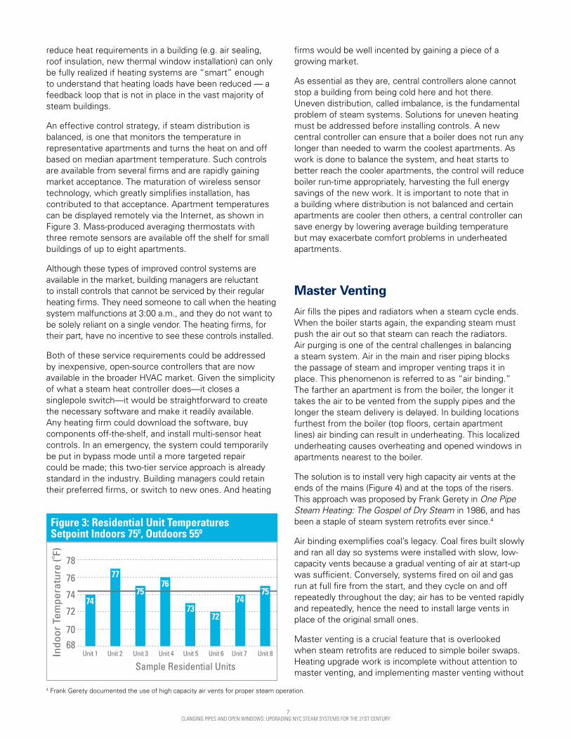
An effective control strategy, if steam distribution is balanced, is one that monitors the temperature in representative apartments and turns the heat on and off based on median apartment temperature. Such controls are available from several firms and are rapidly gaining market acceptance. The maturation of wireless sensor technology, which greatly simplifies installation, has contributed to that acceptance. Apartment temperatures can be displayed remotely via the Internet, as shown in Figure 3. Mass-produced averaging thermostats with three remote sensors are available off the shelf for small buildings of up to eight apartments.
Although these types of improved control systems are available in the market, building managers are reluctant to install controls that cannot be serviced by their regular heating firms. They need someone to call when the heating system malfunctions at 3:00 a.m., and they do not want to be solely reliant on a single vendor. The heating firms, for their part, have no incentive to see these controls installed.
Both of these service requirements could be addressed by inexpensive, open-source controllers that are now available in the broader HVAC market. Given the simplicity of what a steam heat controller does—it closes a singlepole switch—it would be straightforward to create the necessary software and make it readily available. Any heating firm could download the software, buy components off-the-shelf, and install multi-sensor heat controls. In an emergency, the system could temporarily be put in bypass mode until a more targeted repair could be made; this two-tier service approach is already standard in the industry. Building managers could retain their preferred firms, or switch to new ones. And heating
Figure 3: Residential Unit Temperatures Setpoint Indoors 750, Outdoors 550
firms would be well incented by gaining a piece of a growing market.
As essential as they are, central controllers alone cannot stop a building from being cold here and hot there. Uneven distribution, called imbalance, is the fundamental problem of steam systems. Solutions for uneven heating must be addressed before installing controls. A new central controller can ensure that a boiler does not run any longer than needed to warm the coolest apartments. As work is done to balance the system, and heat starts to better reach the cooler apartments, the control will reduce boiler run-time appropriately, harvesting the full energy savings of the new work. It is important to note that in a building where distribution is not balanced and certain apartments are cooler then others, a central controller can save energy by lowering average building temperature but may exacerbate comfort problems in underheated apartments.
Master Venting Air fills the pipes and radiators when a steam cycle ends. When the boiler starts again, the expanding steam must push the air out so that steam can reach the radiators. Air purging is one of the central challenges in balancing a steam system. Air in the main and riser piping blocks the passage of steam and improper venting traps it in place. This phenomenon is referred to as “air binding.” The farther an apartment is from the boiler, the longer it takes the air to be vented from the supply pipes and the longer the steam delivery is delayed. In building locations furthest from the boiler (top floors, certain apartment lines) air binding can result in underheating. This localized underheating causes overheating and opened windows in apartments nearest to the boiler.
The solution is to install very high capacity air vents at the ends of the mains (Figure 4) and at the tops of the risers. This approach was proposed by Frank Gerety in One Pipe Steam Heating: The Gospel of Dry Steam in 1986, and has been a staple of steam system retrofits ever since.4
Air binding exemplifies coal’s legacy. Coal fires built slowly and ran all day so systems were installed with slow, low-capacity vents because a gradual venting of air at start-up was sufficient. Conversely, systems fired on oil and gas run at full fire from the start, and they cycle on and off repeatedly throughout the day; air has to be vented rapidly and repeatedly, hence the need to install large vents in place of the original small ones.
Master venting is a crucial feature that is overlooked when steam retrofits are reduced to simple boiler swaps. Heating upgrade work is incomplete without attention to master venting, and implementing master venting without
4 Frank Gerety documented the use of high capacity air vents for proper steam operation.

8 CLANGING PIPES AND OPEN WINDOWS: UPGRADING NYC STEAM SYSTEMS FOR THE 21ST CENTURY
control of boilers can also be problematic. If the boiler is the proper size and properly controlled, then the new, larger vents will be silent, because there is less airflow restriction. The vents can be intolerably loud when the boiler is too large or poorly controlled and the vents can even squirt water if the boiler is making wet steam.
Two-Pipe Steam System Balancing and ControlSteam systems fall into two categories: one-pipe and two-pipe. Two-pipe steam is mostly found in buildings above six stories in height. Given how big these systems are and how amenable they are to improvement, they should be the focus of energy conservation work.
Each radiator connects to two pipes in a two-pipe steam system: the supply pipe carries steam to the radiator, and the return pipe carries away the water that forms as the steam condenses. A steam trap is located between the radiator and the return pipe (Figure 5); its function is to block steam from entering the return piping. A certain percentage of traps fail in a way that is very difficult to detect. As failed traps accumulate, a two-pipe system becomes radically imbalanced. Most apartments become drastically overheated as the system runs ever longer in an effort to get heat to the coldest apartments, all the while wasting valuable steam through failed traps.
The solution is to either perform a costly, frequent, and invasive replacement of all steam traps or equip each radiator with an orifice plate. An orifice plate is a small
Figure 4: Steam Venting
Figure 5: In-Unit Steam Trap
Figure 6: Orifice Plate
Figure 5: Two-Pipe Steam Thermostatic Radiator Valve (TRV)
© S
teve
n W
inte
r A
ssoc
iate
s, In
c. 2
014
© S
teve
n W
inte
r A
ssoc
iate
s, In
c. 2
014
metal plate about the size and shape of a bottle cap. The orifice plate can be inserted into the radiator’s hand valve in approximately five minutes, by handymen or plumbers. The plates never wear out and they not only obviate the need for radiator steam traps, but also help balance the steam system. Note that this discussion pertains to supply -line orifice plates only. Return-line orifice plates work on different principles and are widely criticized. On the return side, the orifice would not reduce overheating as steam would not be restricted. Steam can pass through an orifice plate; when installed on the supply line, the orifice is sized to allow a set amount of steam to enter the radiator (the amount which will condense).
According to a study by the Department of Energy’s Advanced Manufacturing Office, steam traps should
9 CLANGING PIPES AND OPEN WINDOWS: UPGRADING NYC STEAM SYSTEMS FOR THE 21ST CENTURY
Figure 8: Radiant barrier installed
be replaced every 3–5 years based on manufacturer guidelines.5 In principle, Local Law 87 requires steam traps to effectively be replaced at least once every 10 years in order to demonstrate compliance. Orifice plates eliminate the need for steam traps at radiators, allowing current city regulations to be complied with in the simplest manner.
Steam traps at radiators tend to fail in the open position and can be left in place when orifice plates are installed. It is important to note that main line steam traps must be functioning and maintained even if the need for in-unit radiator traps is eliminated because of the installation of orifice plates.
Orifice plates enable thermostatic radiator valves (TRVs) to work extremely well. Orifice plates bring the steam system into balance so that resident-level controls become effective. TRVs will not work well if they are installed in a system with steam in the returns. TRVs sense room-air temperature and control the flow of steam into the radiator so as to maintain comfort. They are simple devices that require no wiring, and are long- established in the marketplace.
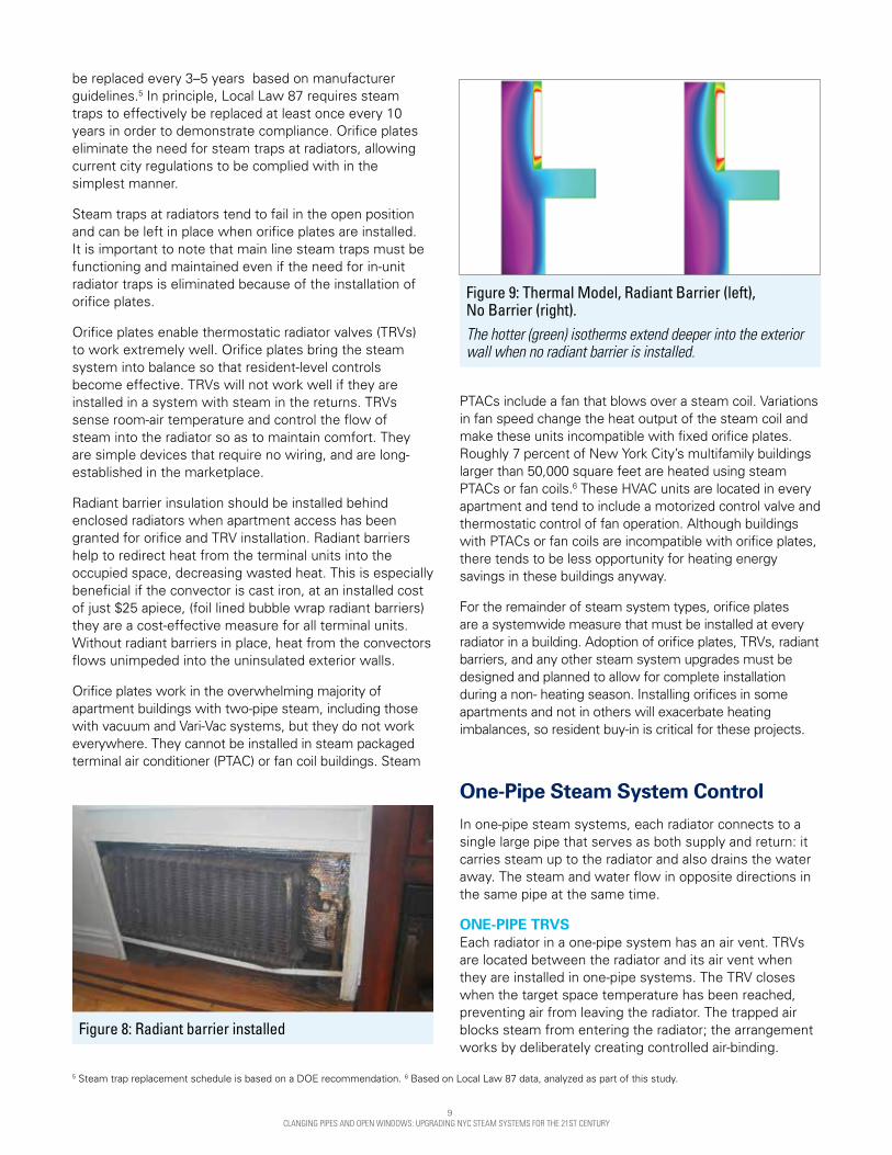
Radiant barrier insulation should be installed behind enclosed radiators when apartment access has been granted for orifice and TRV installation. Radiant barriers help to redirect heat from the terminal units into the occupied space, decreasing wasted heat. This is especially beneficial if the convector is cast iron, at an installed cost of just $25 apiece, (foil lined bubble wrap radiant barriers) they are a cost-effective measure for all terminal units. Without radiant barriers in place, heat from the convectors flows unimpeded into the uninsulated exterior walls.
Orifice plates work in the overwhelming majority of apartment buildings with two-pipe steam, including those with vacuum and Vari-Vac systems, but they do not work everywhere. They cannot be installed in steam packaged terminal air conditioner (PTAC) or fan coil buildings. Steam
PTACs include a fan that blows over a steam coil. Variations in fan speed change the heat output of the steam coil and make these units incompatible with fixed orifice plates. Roughly 7 percent of New York City’s multifamily buildings larger than 50,000 square feet are heated using steam PTACs or fan coils.6 These HVAC units are located in every apartment and tend to include a motorized control valve and thermostatic control of fan operation. Although buildings with PTACs or fan coils are incompatible with orifice plates, there tends to be less opportunity for heating energy savings in these buildings anyway.
For the remainder of steam system types, orifice plates are a systemwide measure that must be installed at every radiator in a building. Adoption of orifice plates, TRVs, radiant barriers, and any other steam system upgrades must be designed and planned to allow for complete installation during a non- heating season. Installing orifices in some apartments and not in others will exacerbate heating imbalances, so resident buy-in is critical for these projects.
One-Pipe Steam System Control In one-pipe steam systems, each radiator connects to a single large pipe that serves as both supply and return: it carries steam up to the radiator and also drains the water away. The steam and water flow in opposite directions in the same pipe at the same time.
ONE-PIPE TRVS Each radiator in a one-pipe system has an air vent. TRVs are located between the radiator and its air vent when they are installed in one-pipe systems. The TRV closes when the target space temperature has been reached, preventing air from leaving the radiator. The trapped air blocks steam from entering the radiator; the arrangement works by deliberately creating controlled air-binding.
Figure 9: Thermal Model, Radiant Barrier (left), No Barrier (right). The hotter (green) isotherms extend deeper into the exterior wall when no radiant barrier is installed.
5 Steam trap replacement schedule is based on a DOE recommendation. 6 Based on Local Law 87 data, analyzed as part of this study.
10 CLANGING PIPES AND OPEN WINDOWS: UPGRADING NYC STEAM SYSTEMS FOR THE 21ST CENTURY
One-pipe TRVs do not control the steam itself, they can only control the venting of air. Unless a system is operated at extremely low steam pressure (±1 psi), steam can enter the radiator even when the one-pipe TRV is closed. Systems with oversized boilers cannot maintain such low pressure, so TRVs may not be effectve. Anecdotally, one-pipe TRVs work well in small buildings with properly sized boilers. They may also work in larger buildings with properly sized boilers, but their performance in buildings with oversized boilers needs to be tested.
RADIATOR COZIES The Cozy is a proprietary insulating enclosure developed by Radiator Labs that wraps around a radiator. It includes a thermostatically-controlled fan that runs whenever the room needs heat. The Cozy is a promising option for larger one-pipe systems with oversized boilers, given that one-pipe TRVs are likely to work poorly in those situations.
Steam Quality All steam heating systems need dry steam—-water vapor with few entrained water droplets—to operate optimally. Wet steam causes water hammer (clanging pipes), squirting vents, and water accumulations at the ends of steam mains. Water accumulation blocks steam from reaching apartments; tenants complain, the heat gets turned up, and most of the building becomes overheated. Wet steam is an energy conservation issue because of this cycle. Frank Gerety’s seminal work is subtitled “The Gospel of Dry Steam” as a reflection of the importance of this issue.
Figure 10: 1-pipe steam TRV
Figure 11: Anode Bar
CLEANING THE BOILER WATER Wet steam has several causes. The easiest to address is oil-contaminated boiler water, which frequently results from heating system maintenance work. It can be addressed by cleaning with detergents and by skimming the boiler.
Both tasks can be done by trained building personnel, provided the proper boiler plant piping has been added as part of a heating system retrofit.
ANODE BARS The treatment of boiler water with chemicals to prevent corrosion is another common cause of wet steam. Older high-performance formulations were banned due to their extreme toxicity, and field experience has indicated that modern products can cause wet steam formation.
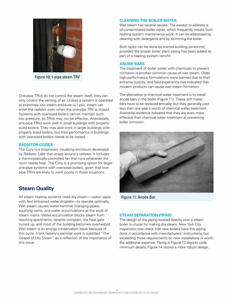
The alternative to chemical water treatment is to install anode bars in the boiler (Figure 11). These soft metal bars have to be replaced annually, but they generally cost less than one year’s worth of chemical water treatment. Anecdotal evidence indicates that they are even more effective than chemical water treatment at preventing boiler corrosion.
STEAM SEPARATION PIPING The design of the piping located directly over a steam boiler is crucial for making dry steam. New York City inspectors now check that new boilers have this piping done in accordance with manufacturers’ instructions, but exceeding those requirements on new installations is worth the additional expense. Piping in Figure 12 depicts code minimum details; Figure 14 shows a more robust design.

11 CLANGING PIPES AND OPEN WINDOWS: UPGRADING NYC STEAM SYSTEMS FOR THE 21ST CENTURY
Figure 12: Steam Separation Piping
POOR DESIGN OF LARGE STEEL BOILERS Large steel boilers are the most problematic cause of wet steam. They are incapable of producing dry steam when run at full output in a heating system. At full output, the velocity of the steam rises, increasing the likelihood of carryover, which in turn leads to wet steam. The boiler steam outlets are too small and retrofitting these boilers is prohibitively expensive or may introduce code issues, so the time of installation is the crucial point for intervention. Boiler steam outlets are designed for maximum pressure rather than the pressure at which steam distribution systems are designed to operate. The lower distribution pressure requires a larger boiler steam outlet.
Based on SWA’s experience and observations, steel boilers are typically oversized by 100 percent due to entrenched practices, and then are run at 50 percent fire to compensate for oversizing. A better approach would be to put in properly sized boilers in the first place and equip them with adequate outlets. This would reduce initial and operating costs, make the system work better, and improve the effectiveness of energy-conserving measures.
12 CLANGING PIPES AND OPEN WINDOWS: UPGRADING NYC STEAM SYSTEMS FOR THE 21ST CENTURY
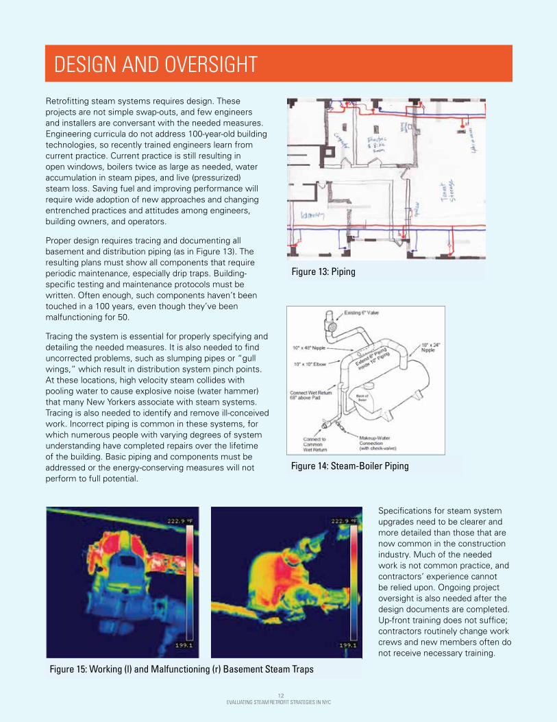
Figure 15: Working (l) and Malfunctioning (r) Basement Steam Traps
Retrofitting steam systems requires design. These projects are not simple swap-outs, and few engineers and installers are conversant with the needed measures. Engineering curricula do not address 100-year-old building technologies, so recently trained engineers learn from current practice. Current practice is still resulting in open windows, boilers twice as large as needed, water accumulation in steam pipes, and live (pressurized) steam loss. Saving fuel and improving performance will require wide adoption of new approaches and changing entrenched practices and attitudes among engineers, building owners, and operators.
Proper design requires tracing and documenting all basement and distribution piping (as in Figure 13). The resulting plans must show all components that require periodic maintenance, especially drip traps. Building-specific testing and maintenance protocols must be written. Often enough, such components haven’t been touched in a 100 years, even though they’ve been malfunctioning for 50.
Tracing the system is essential for properly specifying and detailing the needed measures. It is also needed to find uncorrected problems, such as slumping pipes or “gull wings,” which result in distribution system pinch points. At these locations, high velocity steam collides with pooling water to cause explosive noise (water hammer) that many New Yorkers associate with steam systems. Tracing is also needed to identify and remove ill-conceived work. Incorrect piping is common in these systems, for which numerous people with varying degrees of system understanding have completed repairs over the lifetime of the building. Basic piping and components must be addressed or the energy-conserving measures will not perform to full potential.
Figure 14: Steam-Boiler Piping
Figure 13: Piping
DESIGN AND OVERSIGHT
Specifications for steam system upgrades need to be clearer and more detailed than those that are now common in the construction industry. Much of the needed work is not common practice, and contractors’ experience cannot be relied upon. Ongoing project oversight is also needed after the design documents are completed. Up-front training does not suffice; contractors routinely change work crews and new members often do not receive necessary training.
12 EVALUATING STEAM RETROFIT STRATEGIES IN NYC

13 CLANGING PIPES AND OPEN WINDOWS: UPGRADING NYC STEAM SYSTEMS FOR THE 21ST CENTURY
THE CASE FOR STEAM UPGRADES Potential cost savings from improving steam distribution systems are significant. Repairing and upgrading systems with the methods presented in this report are projected to result in $41 million and $75 million (or $147 million if including steam trap offset costs) annual cost savings across New York City one-pipe and two-pipe multifamily buildings, respectively.
On an individual building level, the economics vary by fuel type. The shortest payback for steam retrofits is realized in buildings with district steam as a fuel source; buildings using natural gas have longer paybacks due to current low fuel prices. Table 1 presents an overview of the economics for one and twopipe steam system upgrades.
TABLE 1: PROJECTED SAVINGS
Distribution System
Energy Efficiency Upgrade Projected
Capital Cost per Unit, Including Controls
Heating Energy
Savings8
Annual Savings per Dwelling Unit9 Maintenance
Cost Savings per Unit
Simple Payback (years) not including maintenance savings
System Upgrade
Radiator Control District
SteamFuel Oil
Natural Gas
District Steam
Fuel Oil
Natural Gas
One-Pipe Steam
Master venting, control panel
TRV $910 10% $130 $110 $60 N/A 7 8 15
Two-Pipe Steam
Master venting, control panel
TRV, orifice plate, radiant
barrier $1,120 20% $310 $260 $130 $210 every
3 years 4 4 8
Distribution System
Citywide Savings Potential (EE + maint.)
Citywide Savings Potential (EE only)10
Carbon Savings Metric tons/year11
One-Pipe Steam $40,700,000 $40,700,000 137,500
Two-Pipe Steam $106,000,000 $75,500,000 174,300
Incentive programs can further improve the simple payback for eligible properties. Utility companies and the New York State Energy Research and Development Authority (NYSERDA) may have incentive monies that can be applied towards these projects, which can offset technical assistance or capital costs.
Beyond reduced fuel costs are countless benefits that greatly improve resident comfort that cannot be monetized. Added to that is the reduced disruption residents will experience from clanging pipes and radiator service. Radiator maintenance costs will be reduced and the time spent on heating related service calls will greatly be diminished.
13 EVALUATING STEAM RETROFIT STRATEGIES IN NYC
8 Projected savings are based on SWA’s experience upgrading steam systems in NYC multifamily properties. 9 Assumptions: Fuel costs of $3.20/gallon (#2 oil), $1.21/therm (natural gas), and $33/Mlbs (district steam). 10 Based on Local Law 87 data, analyzed as part of this study.
11 Carbon savings are calculated using NYC Carbon Challenge coefficients (fixed at 2005 levels) for each fuel type.
CASE STUDY A prewar mid-rise 77 unit co-op in Washington Heights addressed their steam system and reduced their oil bill by 21 percent.

14 CLANGING PIPES AND OPEN WINDOWS: UPGRADING NYC STEAM SYSTEMS FOR THE 21ST CENTURY
CONCLUSIONThis report seeks to draw the attention of the multifamily building sector, policymakers, and the general public to the compelling need to upgrade NYC’s steam heating systems – systems that are responsible for heating 76 percent of large (50,000 square feet and larger ) multifamily buildings in the city. These outdated systems are inefficient, waste energy, and significantly contribute to NYC’s climate-warming pollution. They are expensive to operate and do not provide a satisfying and acceptable level of comfort to our many multifamily residents.
Fortunately, we do know how to effectively upgrade NYC’s steam heating systems so that they waste less energy, are more economical to operate, and produce more comfortable temperatures for residents. Most importantly, these upgrades must be approached from a comprehensive design and implementation perspective -- no single measure on its own will produce the desired results. This report identifies a core set of best practices with near universal applicability to NYC’s multifamily stock.
It is difficult to imagine an economically viable pathway to New York City’s carbon reduction goals that does not address steam distribution systems across the multifamily sector. This report, by highlighting proven technical approaches to reducing steam heating systems’ inefficiencies, is the first step. Next must come a concerted policy focus to catalyze the adoption of these proven but underused approaches, accompanied by effective education and incentive programs for building owners, operators, and engineers.

15 CLANGING PIPES AND OPEN WINDOWS: UPGRADING NYC STEAM SYSTEMS FOR THE 21ST CENTURY
APPENDIX A: BOILER SIZING EFFECTS OF OVERSIZED BOILERS An oversized boiler puts out too much steam, so it has to shut off frequently in order to allow the steam pressure to dissipate. Every time it does so, air is blown through the boiler for several minutes. This is a code-mandated safety measure. The air purge pulls heat out of the boiler and sends it up the chimney, and many boilers are so oversized that they have to repeat this purge cycle every few minutes. The fuel waste is significant.
The boiler’s cycling on and off also makes the building steam pressure fluctuate. This reduces the effectiveness of many energy-conserving measures, such as the installation of one-pipe TRVs, which rely on stable steam pressure. Boiler sizing is a crucial issue to address in any effort to improve steam system fuel efficiency.
TRADITIONAL METHOD OF SIZING STEAM BOILERS The traditional way to properly size a steam boiler is to measure a building’s radiators and calculate their total heat output through the Equivalent Direct Radiation (EDR) method. Radiator output data is available in charts (Figure 17 is an example). Once the building radiators’ total heat output is calculated, that figure is multiplied by a piping and pickup (P&P) factor to arrive at a boiler size.
The first difficulty with this method is that it requires getting into apartments. Many installers and engineers will go into an inadequate sample of apartments and extrapolate total connected building load from those visits. The other issue is that no single P&P factor is applicable to all buildings. Traditionally the figure is given in the range of 1.3 to 1.5, but many New York City systems have a P&P factor closer to 2. The factor varies widely and unpredictably from building to building. A factor of 2 appears to always deliver an adequate boiler, but at the cost of some oversizing.
Figure 17: Steam EDR Chart

16 CLANGING PIPES AND OPEN WINDOWS: UPGRADING NYC STEAM SYSTEMS FOR THE 21ST CENTURY
Steam Outlet Velocity Chart
200
150
100
50
0
78
74
76
78
72
70
68
50
Unit 1 Unit 2 Unit 3 Unit 4 Unit 5 Unit 6 Unit 7 Unit 8
60 70 80 100 125 150 175 200 250 300 350
Stea
m E
xit V
eloc
ity (F
t/Sec
)
Boiler Size (bHP)
Sample Residential Units
■ Steam Velocity with Stock Steam Outlet■ Maximum Velocity for Good Operation
Residential Unit TemeraturesSetpoint Indoors 750
Indo
or T
empe
ratu
re (
F)0
74
7776
7372
7475 75
Figure 18: Steam Outlet Velocity ChartTEST-FIRE METHOD OF SIZING STEAM BOILERS An existing boiler can be used to accurately gauge a steam system’s requirements. The burner’s service firm should temporarily reduce the boiler’s firing rate to as low as it can go. The cold system with reduced firing rate should be restarted and steam production should be timed. The burner technician should increase the firing rate in 25 percent increments until the boiler is able to produce 2 PSI of system pressure in 30 minutes or less in a one-pipe steam system beginning from a cold start. Once it does, that firing rate is the right boiler size for the system.
The test is more involved in a two-pipe system. It should continue for three hours since the heating load can increase as air is gradually removed from the system. It might be necessary to add an additional hour and a half due to the complications created by these systems’ severe air binding where distribution upgrades have not been performed. The test-fire method is straightforward for one-pipe systems, but additional study would improve its effectiveness for sizing boilers for two-pipe systems. This method is not applicable in systems with fan-assisted heaters.
This test-firing procedure is not only more accurate than the EDR method, it is also easier and less expensive. It directly measures the system’s load and uses the precise skills possessed by burner service firms. The existence of an easy way to size steam boilers can greatly ease the otherwise complex process of getting accurately sized boilers installed.
INCREASING STEAM OUTLET SIZE Steel boilers larger than about 100 bHP come with steam outlets that are too small. The smaller the outlet,the faster the steam has to flow (see Figure 18), and the more water gets carried out of the boiler. The resulting wet steam causes such significant problems that burner technicians and building superintendents routinely hold these boilers to half fire. Since that halves the boiler’s steam production, it has the same effect as doubling the boiler’s outlet size. Steam velocity is cut in half, less water is carried out, and the drier steam that results causes fewer problems.
Holding the boiler to 50 percent capacity is an option when the boiler is twice as large as needed, but an accurately sized boiler has to run at full output during system startup. It follows that accurately sized large steel boilers will need larger-than-stock steam outlets to prevent wet steam formation.
WHY STEAM BOILERS CANNOT BE SIZED BASED ON BUILDING HEAT LOSS If a boiler produces only half as much steam as the radiators can accept, the building’s radiators do not get half- filled with steam. Instead, half the radiators get hot and half stay cold. A boiler always has to put out enough steam each cycle to fill all of the radiators to ensure even heating, regardless of the outdoor temperature. If the roof gets insulated and the windows are replaced with better ones, the boiler still has to completely fill up all of the radiators. The boiler can be smaller only if the radiators are made smaller. Improving the building skin and decreasing building heat load does not allow a steam boiler to be downsized. A steam boiler has to be sized based on connected radiation, not on building heat loss. This is also why a boiler cannot be sized accurately based on rules of thumb regarding building size; a building’s size is not directly related to the extent of the building’s existing connected radiation.
BUILDING OWNER EDUCATION Current New York City regulations allow any existing boiler to be replaced by another one the same size, no matter how oversized it may be. This perpetuates fuel waste from oversizing, but regulation alone will not suffice to get boilers sized properly. Sensible regulations are needed, but will only be effective if there is sufficient owner education to create a market demand to offset engineers’ and installers’ incentives to oversize.
One strategy is to require filing engineers to supply building owners with city-designed materials that explain the drawbacks of oversized boilers. This education would most likely be effective given that proper sizing generally reduces the owner’s first cost. Many owners would welcome information that speaks to their decision-making process, but that information is currently difficult for them to find.

17 CLANGING PIPES AND OPEN WINDOWS: UPGRADING NYC STEAM SYSTEMS FOR THE 21ST CENTURY
APPENDIX B: BURNER MODULATION BENEFITS OF MODULATION The burner combines the heating fuel (gas or oil) with air, and sends the mixture into the boiler to be burned. The burner controls how much steam the boiler makes by controlling how much fuel the boiler consumes.
Sophisticated burners vary their firing rate to meet the steam system’s minute-by-minute needs. This modulation is crucial for efficiency. As steam pressure builds in a heating system, a modulating burner reduces the boiler’s steam output so that the boiler can continue to run at a lower rate rather than shutting off. This prevents wasteful purging and short cycling, and makes energy-conserving measures more effective.
The current New York City Building Code requires modulation on boilers above 100 boiler horsepower (bHP). The rule should be strengthened so that modulation is required on all boilers above 20 bHP. The equipment needed to satisfy such a requirement has long been available in the marketplace.
TURNDOWN An important aspect of modulation is turndown, which represents how much a burner can lower its firing rate. If a burner’s high-fire rate is three times its low-fire rate, its turndown is 3:1. Present turndown requirements in the building code are modest, and should be strengthened. At a minimum, a turndown of 3:1 should be required on all boilers 30 bHP and up.
MODULATION TYPE Modulation comes as “Low-High-Off,” “Low-High-Low,” and “Full.” Low-High-Off is a safety setting but does not save fuel. Low-High-Low burners have two firing rates, low and high, while full modulation burners smoothly vary their firing rate throughout the firing range, much like a car’s accelerator. Full modulation is the most efficient, and New York City Building Code requires it on oil burners above 175 bHP. This requirement should be strengthened. Full modulation is already a common feature on 75 bHP boilers. It would be feasible to require it on boilers as small as 25 bHP, and it should certainly be required above 50 bHP.
FIELD REALITIES It takes time and skill to adjust a modulating burner, so modulation is sometimes disabled by burner technicians. Other contributors to such practices often include poor conditions in boiler rooms and dilapidated and makeshift equipment, such as a brick being used to prop up a burner component, as shown in Figure 16. Educating owners and building operations staff is essential. Without oversight from the building stakeholders, there is little incentive for outside technicians to thoroughly tune a burner. This issue becomes especially fraught when the fuel provider also holds the maintenance contract for a burner, creating a disincentive for the provider to optimize boiler plant efficiency.
Figure 16: Dilapidated Burner
18 CLANGING PIPES AND OPEN WINDOWS: UPGRADING NYC STEAM SYSTEMS FOR THE 21ST CENTURY
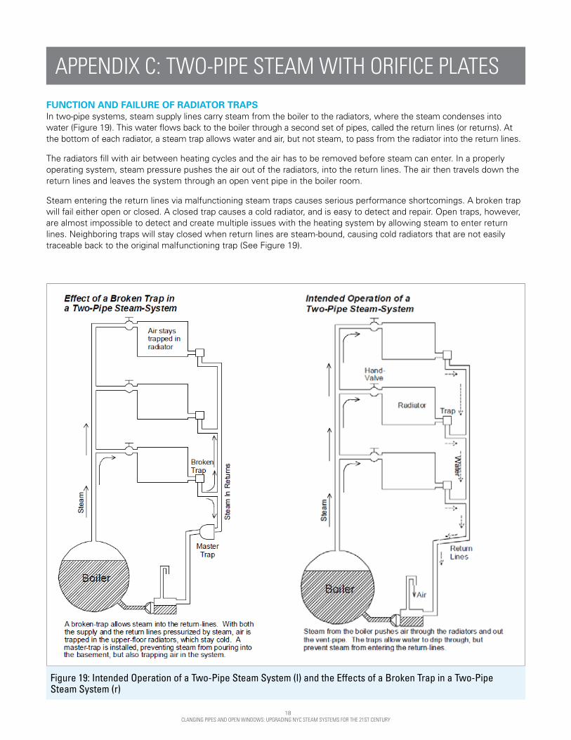
FUNCTION AND FAILURE OF RADIATOR TRAPS In two-pipe systems, steam supply lines carry steam from the boiler to the radiators, where the steam condenses into water (Figure 19). This water flows back to the boiler through a second set of pipes, called the return lines (or returns). At the bottom of each radiator, a steam trap allows water and air, but not steam, to pass from the radiator into the return lines.
The radiators fill with air between heating cycles and the air has to be removed before steam can enter. In a properly operating system, steam pressure pushes the air out of the radiators, into the return lines. The air then travels down the return lines and leaves the system through an open vent pipe in the boiler room.
Steam entering the return lines via malfunctioning steam traps causes serious performance shortcomings. A broken trap will fail either open or closed. A closed trap causes a cold radiator, and is easy to detect and repair. Open traps, however, are almost impossible to detect and create multiple issues with the heating system by allowing steam to enter return lines. Neighboring traps will stay closed when return lines are steam-bound, causing cold radiators that are not easily traceable back to the original malfunctioning trap (See Figure 19).
Figure 19: Intended Operation of a Two-Pipe Steam System (l) and the Effects of a Broken Trap in a Two-Pipe Steam System (r)
APPENDIX C: TWO-PIPE STEAM WITH ORIFICE PLATES

19 CLANGING PIPES AND OPEN WINDOWS: UPGRADING NYC STEAM SYSTEMS FOR THE 21ST CENTURY
Figure 20: Heat Distribution in a Radiator with an Orifice Plate
With the return lines and supply lines pressurized, air is trapped in the upper-floor radiators so steam cannot reach them. They stay cold. Live steam passes through the return lines and pours from the vent pipe in the boiler room. Heating contractors typically install a master steam trap to prevent this steam discharge. It allows some air to escape but shuts tightly as soon as steam reaches it. Once the master trap closes, no more air can leave the system and lines remain air-bound.
Failed steam traps that allow steam into the return lines also lead to water hammer, which both annoys residents and damages more steam traps. A single open trap sets off a domino effect that destroys trap after trap in the building.
Open traps are extremely difficult to locate because the radiator continues to operate normally, allowing steam in as always. Unless all of the traps are replaced at the same time, some undetected open traps are sure to remain and these will destroy new traps as quickly as they are installed. For this reason, trap manufacturers recommend that every trap in a system be replaced at the same time, every three to five years. Work on such a scale, repeated so often, is unmanageable and insupportably expensive.
INSTALLING ORIFICE PLATES Orifice plates obviate the need for steam traps at each radiator. An orifice plate is about the size and shape of a bottle cap and fits snugly into a radiator’s hand valve. A small hole in the plate restricts the flow of steam to 80 percent of the radiator’s capacity. Reducing the steam entering a radiator ensures that all the steam condenses into water, so that no steam can pass through the radiator into the return lines.
The thermal image Figure 20 shows the orifice plate’s effect. Steam enters the radiator and starts filling it from the top down. Steam never reaches the trap, so the trap is no longer needed and broken traps can no longer have an impact on the system.
The maximum heat output of each radiator is reduced by 20 percent, but this is not a problem. Radiators in older buildings were deliberately made large enough to heat the apartments even with the windows open, and other improvements in building envelopes have rendered original radiators oversized. This is attested to by the countless New York City residents who leave their windows open all winter. In fact, slightly reducing radiator heat output tends to improve comfort. A small, controlled flow of steam into a radiator delivers a more gradual, gentle heat, in contrast to the wild temperature swings more typical of these systems.
In addition, the orifice plates will help to balance the system. Meeting resistance at every radiator, steam will push evenly to the end of each steam line rather than taking the path of least resistance through a handful of radiators nearest the boiler. Orifice plates are an elegantly simple technology dating from the early days of steam heat. They work as well as radiator steam traps in oil- or gas-fired systems, and they never break.

20 CLANGING PIPES AND OPEN WINDOWS: UPGRADING NYC STEAM SYSTEMS FOR THE 21ST CENTURY
APPENDIX D: EMERGING TECHNOLOGIES WIRELESS CONTROLS The emergence of new wireless radiator control technologies is an extremely promising development. Wireless technology as part of a master heating control system, discussed earlier, and has been gaining acceptance. The installation of wireless controls throughout a system and on terminal units requires further evaluation, but will most likely be critical to supporting the scaling up of the best solutions across the sector.
These technologies all make use of modern, wall-mounted thermostats that communicate wirelessly with the radiator control or even with a smart phone, significantly improving the resident interface compared with a traditional TRV. In many cases these technologies take advantage of energy harvesting to power wireless devices by daylight or thermal energy from radiators. Bonded Energy has developed such a TRV specifically for the one-pipe steam market. Magnum Energy / Sentient Buildings offers a product compatible with both one- and two-pipe steam radiators.
Any of the above described radiator control device sensors can be networked to a central control that shuts off the boiler once the sensors show that apartments are warm. Such multisensor controls have been available for decades; thousands are in place already. The savings realized by this capability cannot be solely credited to any one radiator control device alone, and performance is optimized only when the whole system is addressed.
Figure 21: Emerging Radiator Control Technologies
Courtesy of Magnum Energy Solutions / Sentient Buildings: Solar-powered room control module with LCD and controls, with intelligent transmission management for measuring room temperature and for wireless transmission of measured values, occupancy, setpoint, and weekly schedule
Figure 22: The Cozy, by Radiator Labs
A roadblock to market acceptance of new control devices is that they are often not paired with fundamental steam system upgrades. Controls are often viewed as an easy drop-in solution to problems stemming from fundamental system flaws. Established solutions like TRVs have some detractors who cite examples of their failure in systems where the underlying issues were not remedied. This pattern will continue with any new technology that is developed. No technology here is recommended without its being implemented as part of a holistic approach to steam system repair.
THE RADIATOR COZY The Cozy by Radiator Labs is designed to wrap around each radiator and only allow heat to be discharged when a room sensor indicates a need for heating.12 Steam still continues to fill the radiator under the Cozy, even when the room does not need heat.
It is best to prevent steam from entering the radiator in the first place to prevent overheating, as TRVs do, rather than trying to keep the heat bottled up afterwards. In a lot of one-pipe systems with oversized boilers, there may be no better option, but the Cozy is not an ideal solution for two-pipe systems given the superior design and lower cost of two-pipe TRV it orifice plate installations.
FAN A removable fan guarantees proper airflow inside the radiator cover.
12 Radiator Labs http://www.radiatorlabs.com/

21 CLANGING PIPES AND OPEN WINDOWS: UPGRADING NYC STEAM SYSTEMS FOR THE 21ST CENTURY
APPENDIX E: HYDRONIC CONVERSION Some steam systems can be profitably converted to hydronic operation, in which hot water rather than steam circulates through the radiators and piping. Hydronic systems are more efficient, quieter, more comfortable, and more adaptable than steam systems are. Conversions reuse the vast majority of the existing steam system components, generally including all piping and radiators. Steam system components do not wear with age since they are not exposed to much dissolved oxygen. Patched pipes and pipes buried in dirt have to be replaced, but that is usually the extent of replacement needed.
Hydronic conversion is often cost-effective in small buildings with two-pipe steam and is generally very well suited to converted 19th century loft buildings, whose crude steam systems are otherwise not susceptible to much improvement. The existing piping and radiators in these buildings can usually be reused during the conversion process, making the retrofit less invasive. Despite the huge energy savings hydronic conversion delivers (about 40 percent), converting larger systems is generally too expensive to be paid for with fuel savings in a reasonable period of time.
Non-cost benefits of conversion sometimes justify the investment in hydronic conversion in large buildings. At one West Village theater, hydronic conversion silenced the steam hammer that had made the heating system unusable during performances. Conversion cured radical imbalance in a sprawling complex of 19th century buildings See Figure 23. Hydronic conversion can be the best option for retrofitting steam systems in some small buildings.
Figure 23: Hydronic System Piping
REFERENCES
1. The City of New York, Office of the Mayor. PlaNYC New York City Local Law 84 Benchmarking Report. September 2014. http://www.nyc.gov/html/planyc/downloads/pdf/publications/2014_nyc_ll84_benchmarking_report.pdf.
2. The City of New York, Mayor’s Office of Long-Term Planning and Sustainability. One City Built to Last. 2015. http://www.nyc.gov/html/builttolast/assets/downloads/pdf/OneCity.pdf.
3. Frank Gerety. One Pipe Steam Heating: The Gospel of Dry Steam. N.p. 1986. Print.
4. Energy.gov. Office of Energy Efficiency and Renewable Energy. Inspect and Repair Steam Traps. N.p., n.d. Web. http://www.energy.gov/sites/prod/files/2014/05/f16/steam1_traps.pdf
Assumptions for Table 1: Projected Savings It is assumed that buildings reduce indoor temperatures to a balanced 72 degree F winter setting. Capital costs include material, relevant labor, controls, venting, and design fees. Labor rates were included for two-pipe steam installation costs. Labor rates for one-pipe steam and trap replacement capital costs were not included as in-house labor usually does this work. No incentive funding was included in the payback calculations. Not included in the cost savings are operations and maintenance savings realized from reduced resident complaints, obviated steam trap maintenance, and reduced boiler cycling from balanced heating.

22 CLANGING PIPES AND OPEN WINDOWS: UPGRADING NYC STEAM SYSTEMS FOR THE 21ST CENTURY