Clamping devices - 3.imimg.com3.imimg.com/data3/QX/SG/MY-15936012/clamping-devices.pdf ·...
57
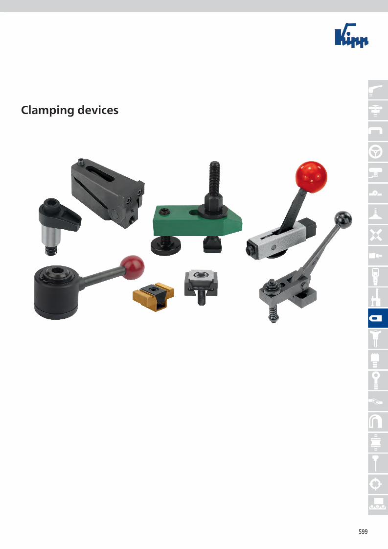
599 Clamping devices
Transcript of Clamping devices - 3.imimg.com3.imimg.com/data3/QX/SG/MY-15936012/clamping-devices.pdf ·...
599
Clamping devices

600
Notes
601
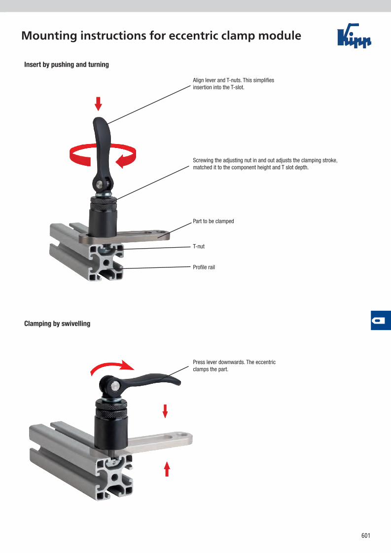
Mounting instructions for eccentric clamp module
Press lever downwards. The eccentric clamps the part.
Align lever and T-nuts. This simplifies insertion into the T-slot.
Screwing the adjusting nut in and out adjusts the clamping stroke, matched it to the component height and T slot depth.
Part to be clamped
T-nut
Profile rail
Insert by pushing and turning
Clamping by swivelling
602
D1
SW 30
L10H1
H2H
D
A
L
H1H2H
A
workpiece / component
adjustment
hammer nutfor 8 mm T-slot
alu profile / machine tableForm B
Form A
hand
force
clamping force
min.
4 /
max
. 12
adjustment
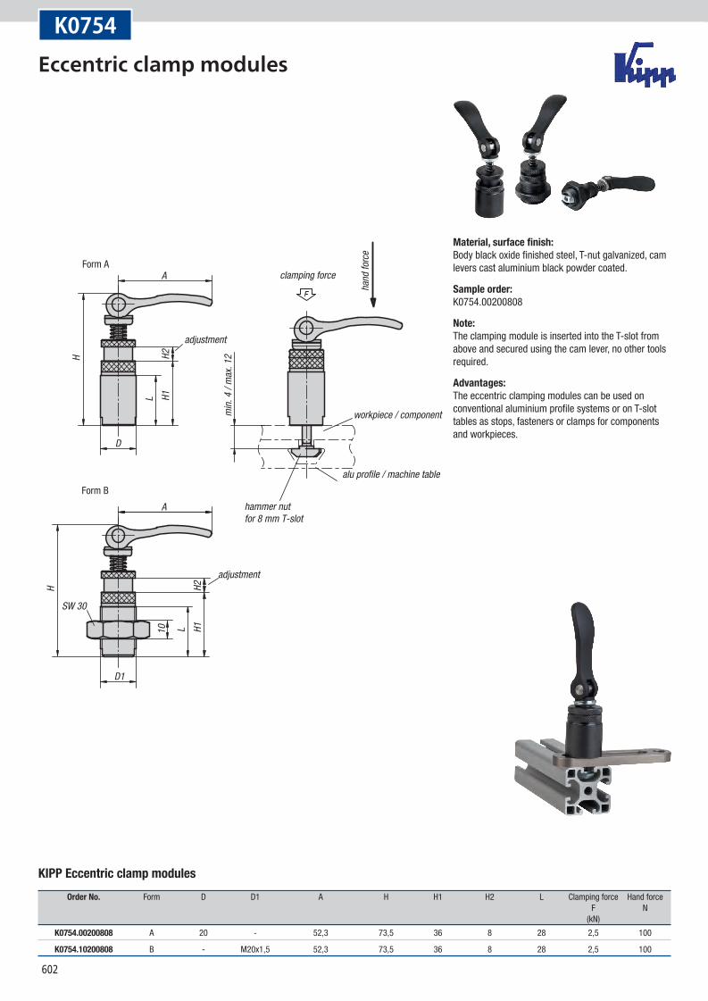
K0754
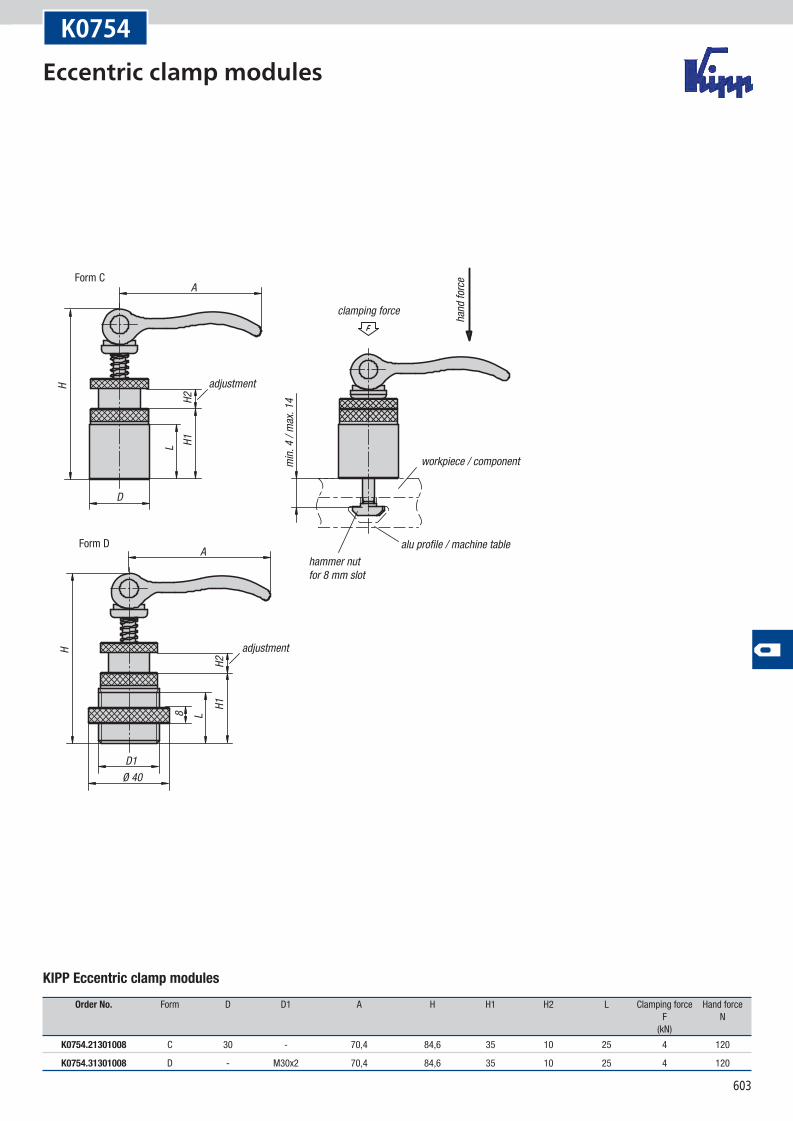
KIPP Eccentric clamp modules
Order No. Form D D1 A H H1 H2 L Clamping force Hand force F N (kN)
K0754.00200808 A 20 - 52,3 73,5 36 8 28 2,5 100
K0754.10200808 B - M20x1,5 52,3 73,5 36 8 28 2,5 100
Material, surface finish:Body black oxide finished steel, T-nut galvanized, cam levers cast aluminium black powder coated.
Sample order:K0754.00200808
Note:The clamping module is inserted into the T-slot from above and secured using the cam lever, no other tools required.
Advantages:The eccentric clamping modules can be used on conventional aluminium profile systems or on T-slot tables as stops, fasteners or clamps for components and workpieces.
Eccentric clamp modules
603
H
D1
L8
Ø 40
A
D
H1H2
L
H
A
H1H2
workpiece / component
adjustment
hammer nutfor 8 mm slot
alu profile / machine table
Form C
Form D
hand
force
clamping force
min.
4 /
max
. 14
adjustment
K0754
KIPP Eccentric clamp modules
Order No. Form D D1 A H H1 H2 L Clamping force Hand force F N (kN)
K0754.21301008 C 30 - 70,4 84,6 35 10 25 4 120
K0754.31301008 D - M30x2 70,4 84,6 35 10 25 4 120
Eccentric clamp modules
604
K0001
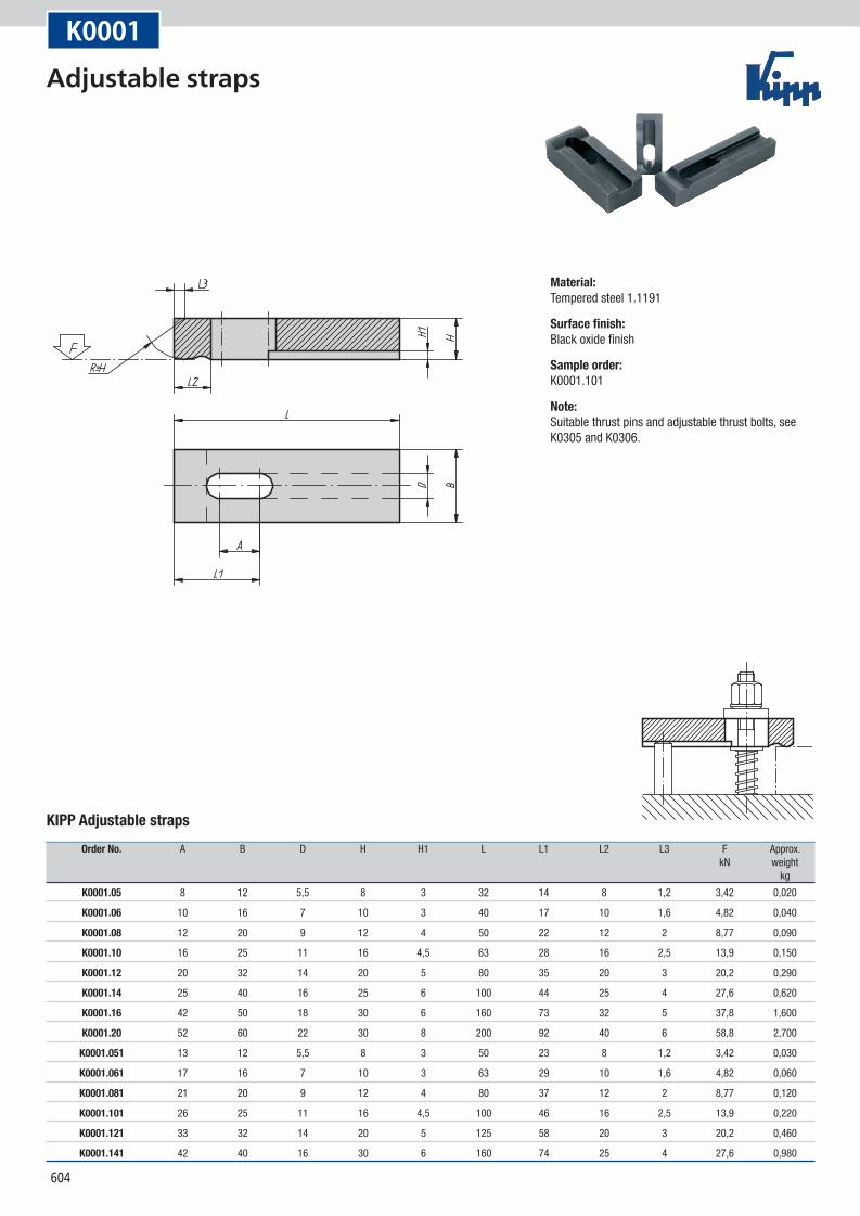
KIPP Adjustable straps
Order No. A B D H H1 L L1 L2 L3 F Approx. kN weight kg
K0001.05 8 12 5,5 8 3 32 14 8 1,2 3,42 0,020
K0001.06 10 16 7 10 3 40 17 10 1,6 4,82 0,040
K0001.08 12 20 9 12 4 50 22 12 2 8,77 0,090
K0001.10 16 25 11 16 4,5 63 28 16 2,5 13,9 0,150
K0001.12 20 32 14 20 5 80 35 20 3 20,2 0,290
K0001.14 25 40 16 25 6 100 44 25 4 27,6 0,620
K0001.16 42 50 18 30 6 160 73 32 5 37,8 1,600
K0001.20 52 60 22 30 8 200 92 40 6 58,8 2,700
K0001.051 13 12 5,5 8 3 50 23 8 1,2 3,42 0,030
K0001.061 17 16 7 10 3 63 29 10 1,6 4,82 0,060
K0001.081 21 20 9 12 4 80 37 12 2 8,77 0,120
K0001.101 26 25 11 16 4,5 100 46 16 2,5 13,9 0,220
K0001.121 33 32 14 20 5 125 58 20 3 20,2 0,460
K0001.141 42 40 16 30 6 160 74 25 4 27,6 0,980
Material:Tempered steel 1.1191
Surface finish:Black oxide finish
Sample order:K0001.101
Note:Suitable thrust pins and adjustable thrust bolts, see K0305 and K0306.
Adjustable straps
605
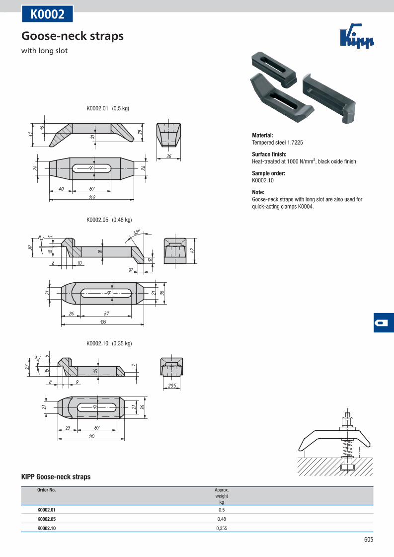
K0002.05
K0002.10
K0002.01
(0,48 kg)
(0,35 kg)
(0,5 kg)
K0002
KIPP Goose-neck straps
Order No. Approx. weight kg
K0002.01 0,5
K0002.05 0,48
K0002.10 0,355
Material:Tempered steel 1.7225
Surface finish:Heat-treated at 1000 N/mm², black oxide finish
Sample order:K0002.10
Note:Goose-neck straps with long slot are also used for quick-acting clamps K0004.
Goose-neck straps with long slot
606
A
B1 B
0.6
A
F
D
G
E1
F
E2
L
D1
K0003
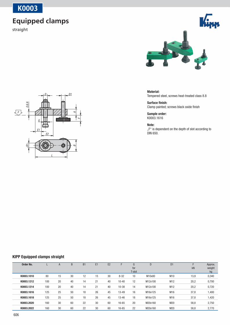
KIPP Equipped clamps straight
Order No. L A B B1 E1 E2 F G D D1 F Approx. for kN weight T-slot kg
K0003.1010 80 15 30 12 15 30 8-32 10 M10x80 M10 13,9 0,340
K0003.1212 100 20 40 14 21 40 10-40 12 M12x100 M12 20,2 0,700
K0003.1214 100 20 40 14 21 40 10-38 14 M12x100 M12 20,2 0,720
K0003.1616 125 25 50 18 26 45 13-49 16 M16x125 M16 37,8 1,400
K0003.1618 125 25 50 18 26 45 13-46 18 M16x125 M16 37,8 1,420
K0003.2020 160 30 60 22 30 60 16-65 20 M20x160 M20 58,8 2,750
K0003.2022 160 30 60 22 30 60 16-65 22 M20x160 M20 58,8 2,770
Material:Tempered steel, screws heat-treated class 8.8
Surface finish:Clamp painted; screws black oxide finish
Sample order:K0003.1616
Note:„F“ is dependent on the depth of slot according to DIN 650.
Equipped clamps straight
607
clam
ping r
ange
strap width 36 mm
slot width "B"
clam
ping r
ange
strap width 36 mm
slot width "B"
clam
ping r
ange
strap width 36 mm
slot width "B"
Size 3-5
Size 2
Size 1
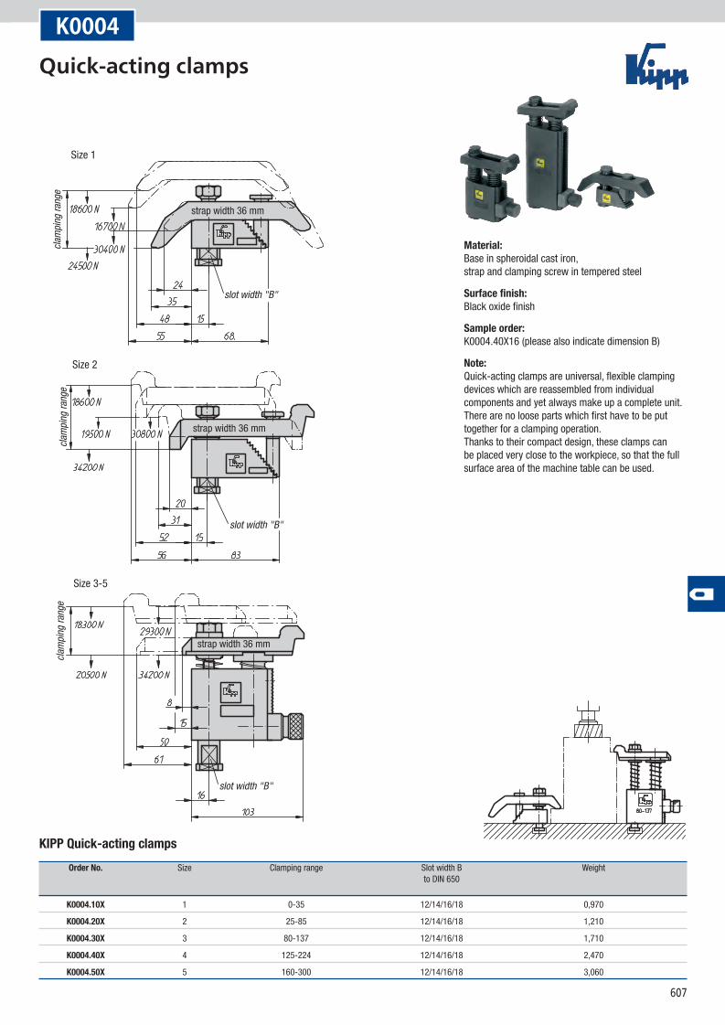
K0004
KIPP Quick-acting clamps
Order No. Size Clamping range Slot width B Weight to DIN 650
K0004.10X 1 0-35 12/14/16/18 0,970
K0004.20X 2 25-85 12/14/16/18 1,210
K0004.30X 3 80-137 12/14/16/18 1,710
K0004.40X 4 125-224 12/14/16/18 2,470
K0004.50X 5 160-300 12/14/16/18 3,060
Material:Base in spheroidal cast iron, strap and clamping screw in tempered steel
Surface finish:Black oxide finish
Sample order:K0004.40X16 (please also indicate dimension B)
Note:Quick-acting clamps are universal, flexible clamping devices which are reassembled from individual components and yet always make up a complete unit. There are no loose parts which first have to be put together for a clamping operation. Thanks to their compact design, these clamps can be placed very close to the workpiece, so that the full surface area of the machine table can be used.
Quick-acting clamps
608
N min.
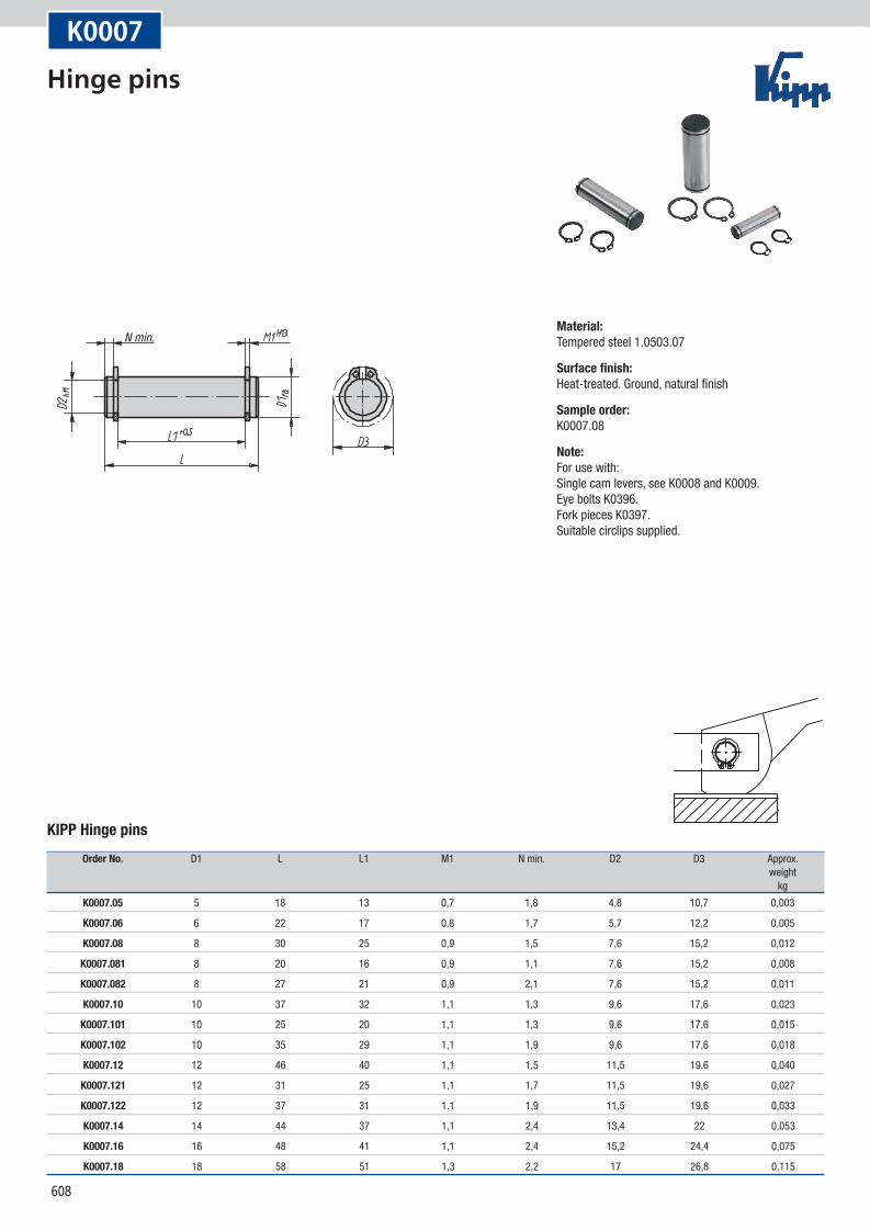
K0007
KIPP Hinge pins
Order No. D1 L L1 M1 N min. D2 D3 Approx. weight kg
K0007.05 5 18 13 0,7 1,8 4,8 10,7 0,003
K0007.06 6 22 17 0,8 1,7 5,7 12,2 0,005
K0007.08 8 30 25 0,9 1,5 7,6 15,2 0,012
K0007.081 8 20 16 0,9 1,1 7,6 15,2 0,008
K0007.082 8 27 21 0,9 2,1 7,6 15,2 0,011
K0007.10 10 37 32 1,1 1,3 9,6 17,6 0,023
K0007.101 10 25 20 1,1 1,3 9,6 17,6 0,015
K0007.102 10 35 29 1,1 1,9 9,6 17,6 0,018
K0007.12 12 46 40 1,1 1,5 11,5 19,6 0,040
K0007.121 12 31 25 1,1 1,7 11,5 19,6 0,027
K0007.122 12 37 31 1,1 1,9 11,5 19,6 0,033
K0007.14 14 44 37 1,1 2,4 13,4 22 0,053
K0007.16 16 48 41 1,1 2,4 15,2 24,4 0,075
K0007.18 18 58 51 1,3 2,2 17 26,8 0,115
Material:Tempered steel 1.0503.07
Surface finish:Heat-treated. Ground, natural finish
Sample order:K0007.08
Note:For use with: Single cam levers, see K0008 and K0009. Eye bolts K0396. Fork pieces K0397. Suitable circlips supplied.
Hinge pins
609
FHL1 ±0,3
H1±0
,3
H±0
,6
base radiusbase radius
F (N)
F (N)H0
500
1000
1500
2000
2500
3000
3500
4000
4500
050 100 150 200 250
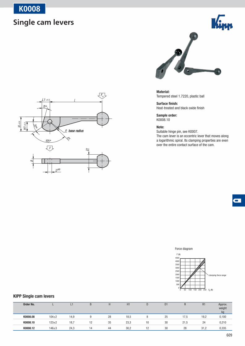
Force diagram
clamping force range
K0008
KIPP Single cam levers
Order No. L L1 B H H1 D D1 R R1 Approx. weight kg
K0008.08 104±2 14,9 9 28 18,5 8 25 17,5 19,2 0,100
K0008.10 123±2 18,7 12 35 23,3 10 30 21,5 24 0,210
K0008.12 146±3 24,3 14 44 30,2 12 30 28 31,2 0,335
Material:Tempered steel 1.7220, plastic ball
Surface finish:Heat-treated and black oxide finish
Sample order:K0008.10
Note:Suitable hinge pin, see K0007. The cam lever is an eccentric lever that moves along a logarithmic spiral. Its clamping properties are even over the entire contact surface of the cam.
Single cam levers
610
FH
H1±0
,3
H±0
,6
L1 ±0,3
base radius
F (N)
F (N)H0
500
1000
1500
2000
2500
3000
3500
4000
4500
050 100 150 200 250
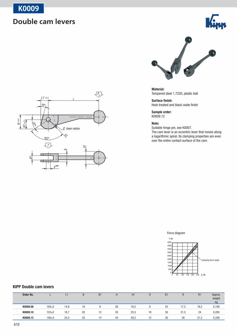
Force diagram
clamping force range
K0009
KIPP Double cam levers
Order No. L L1 B B1 H H1 D D1 R R1 Approx. weight kg
K0009.08 104±2 14,9 16 9 28 18,5 8 25 17,5 19,2 0,100
K0009.10 123±2 18,7 20 12 35 23,3 10 30 21,5 24 0,205
K0009.12 146±3 24,3 25 14 44 30,2 12 30 28 31,2 0,330
Material:Tempered steel 1.7220, plastic ball
Surface finish:Heat-treated and black oxide finish
Sample order:K0009.12
Note:Suitable hinge pin, see K0007. The cam lever is an eccentric lever that moves along a logarithmic spiral. Its clamping properties are even over the entire contact surface of the cam.
Double cam levers
611
A
FH
D2 for hexagon socket screw M6
H1 m
ax.
F (N)
F (N)H0
500100015002000250030003500400045005000
050 100 150 200 250
Force diagram
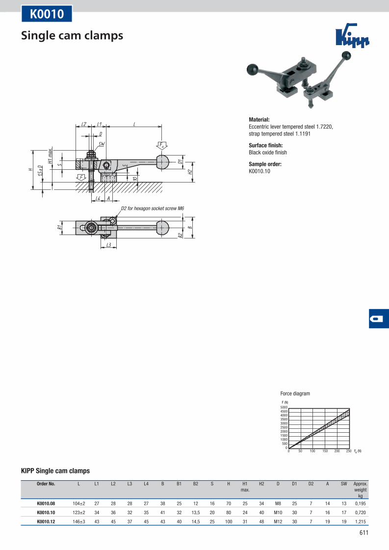
K0010
KIPP Single cam clamps
Order No. L L1 L2 L3 L4 B B1 B2 S H H1 H2 D D1 D2 A SW Approx. max. weight kg
K0010.08 104±2 27 28 28 27 38 25 12 16 70 25 34 M8 25 7 14 13 0,195
K0010.10 123±2 34 36 32 35 41 32 13,5 20 80 24 40 M10 30 7 16 17 0,720
K0010.12 146±3 43 45 37 45 43 40 14,5 25 100 31 48 M12 30 7 19 19 1,215
Material:Eccentric lever tempered steel 1.7220, strap tempered steel 1.1191
Surface finish:Black oxide finish
Sample order:K0010.10
Single cam clamps
612
K0001
FH
For detailed drawing, see
H1 m
ax.
F (N)
F (N)H0
500
1000
1500
2000
2500
050 100 150 200 250
Force diagram
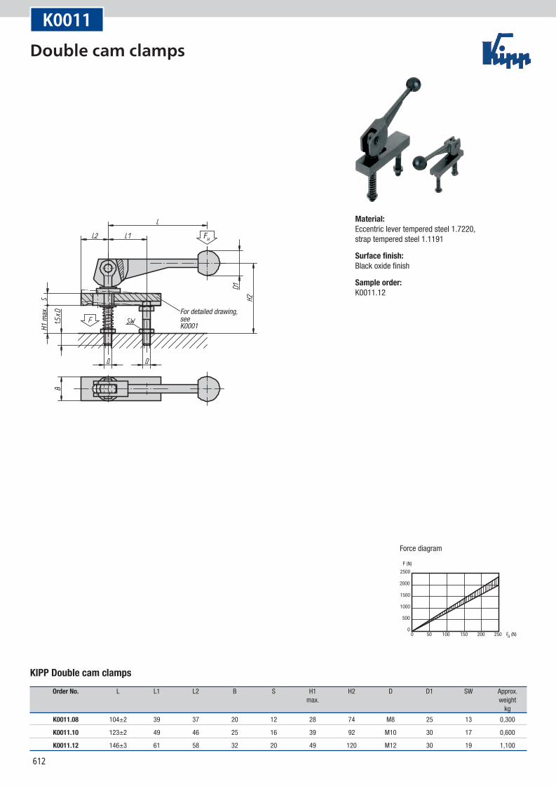
K0011
KIPP Double cam clamps
Order No. L L1 L2 B S H1 H2 D D1 SW Approx. max. weight kg
K0011.08 104±2 39 37 20 12 28 74 M8 25 13 0,300
K0011.10 123±2 49 46 25 16 39 92 M10 30 17 0,600
K0011.12 146±3 61 58 32 20 49 120 M12 30 19 1,100
Material:Eccentric lever tempered steel 1.7220, strap tempered steel 1.1191
Surface finish:Black oxide finish
Sample order:K0011.12
Double cam clamps
613
D -0,10-0,02 D -0,10
-0,02
Form A Form B
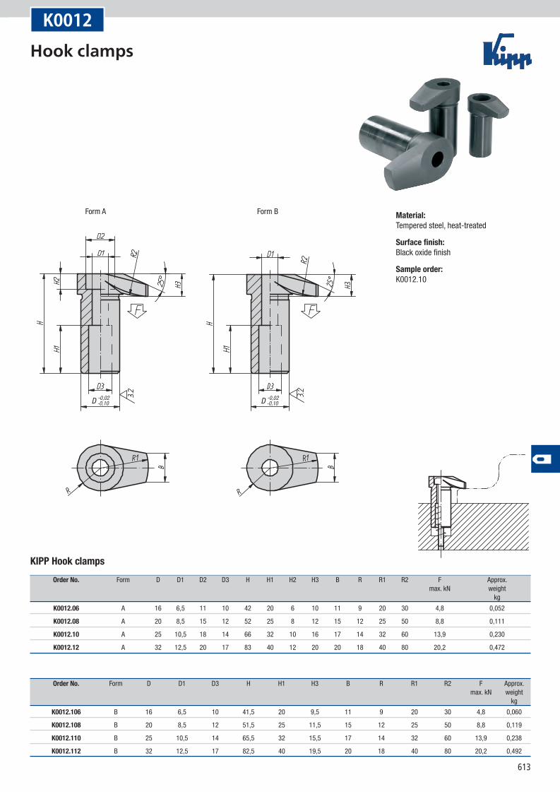
K0012
KIPP Hook clamps
Order No. Form D D1 D2 D3 H H1 H2 H3 B R R1 R2 F Approx. max. kN weight kg
K0012.06 A 16 6,5 11 10 42 20 6 10 11 9 20 30 4,8 0,052
K0012.08 A 20 8,5 15 12 52 25 8 12 15 12 25 50 8,8 0,111
K0012.10 A 25 10,5 18 14 66 32 10 16 17 14 32 60 13,9 0,230
K0012.12 A 32 12,5 20 17 83 40 12 20 20 18 40 80 20,2 0,472
Order No. Form D D1 D3 H H1 H3 B R R1 R2 F Approx. max. kN weight kg
K0012.106 B 16 6,5 10 41,5 20 9,5 11 9 20 30 4,8 0,060
K0012.108 B 20 8,5 12 51,5 25 11,5 15 12 25 50 8,8 0,119
K0012.110 B 25 10,5 14 65,5 32 15,5 17 14 32 60 13,9 0,238
K0012.112 B 32 12,5 17 82,5 40 19,5 20 18 40 80 20,2 0,492
Material:Tempered steel, heat-treated
Surface finish:Black oxide finish
Sample order:K0012.10
Hook clamps
614
T H11
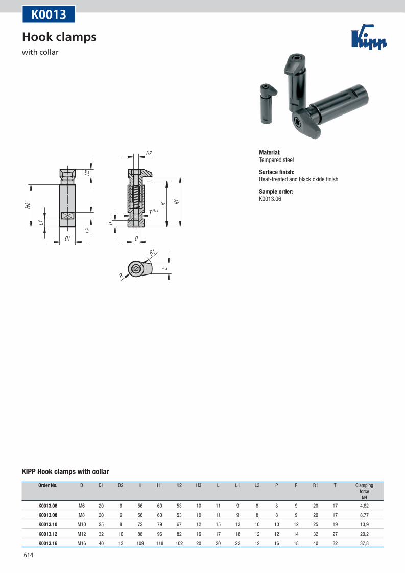
K0013
KIPP Hook clamps with collar
Order No. D D1 D2 H H1 H2 H3 L L1 L2 P R R1 T Clamping force kN
K0013.06 M6 20 6 56 60 53 10 11 9 8 8 9 20 17 4,82
K0013.08 M8 20 6 56 60 53 10 11 9 8 8 9 20 17 8,77
K0013.10 M10 25 8 72 79 67 12 15 13 10 10 12 25 19 13,9
K0013.12 M12 32 10 88 96 82 16 17 18 12 12 14 32 27 20,2
K0013.16 M16 40 12 109 118 102 20 20 22 12 16 18 40 32 37,8
Material:Tempered steel
Surface finish:Heat-treated and black oxide finish
Sample order:K0013.06
Hook clamps with collar
615
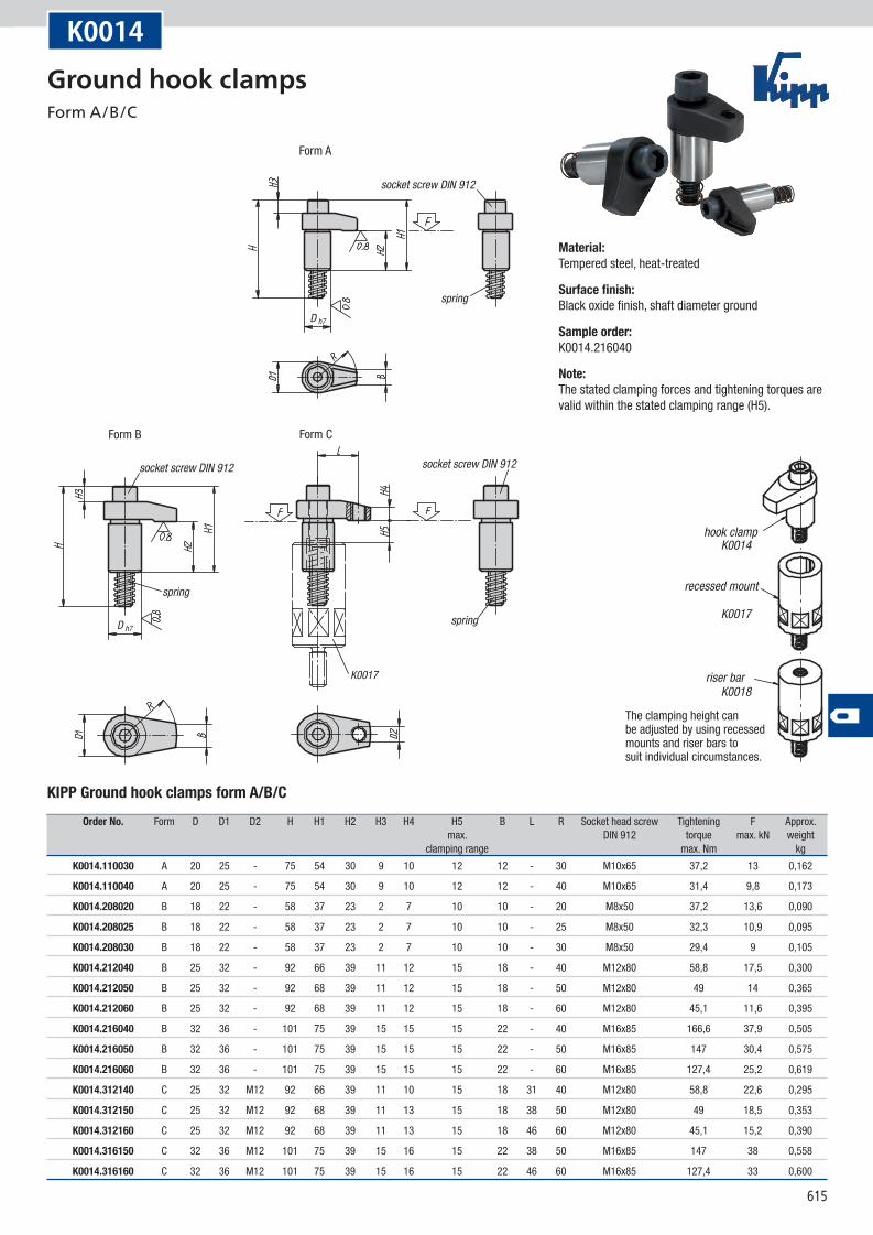
K0017
D h7
D h7spring
socket screw DIN 912socket screw DIN 912
spring
spring
socket screw DIN 912
Form A
Form B Form C
K0014
K0017
K0018
hook clamp
recessed mount
riser bar
The clamping height can be adjusted by using recessed mounts and riser bars to suit individual circumstances.
K0014
KIPP Ground hook clamps form A/B/C
Order No. Form D D1 D2 H H1 H2 H3 H4 H5 B L R Socket head screw Tightening F Approx. max. DIN 912 torque max. kN weight clamping range max. Nm kg
K0014.110030 A 20 25 - 75 54 30 9 10 12 12 - 30 M10x65 37,2 13 0,162
K0014.110040 A 20 25 - 75 54 30 9 10 12 12 - 40 M10x65 31,4 9,8 0,173
K0014.208020 B 18 22 - 58 37 23 2 7 10 10 - 20 M8x50 37,2 13,6 0,090
K0014.208025 B 18 22 - 58 37 23 2 7 10 10 - 25 M8x50 32,3 10,9 0,095
K0014.208030 B 18 22 - 58 37 23 2 7 10 10 - 30 M8x50 29,4 9 0,105
K0014.212040 B 25 32 - 92 66 39 11 12 15 18 - 40 M12x80 58,8 17,5 0,300
K0014.212050 B 25 32 - 92 68 39 11 12 15 18 - 50 M12x80 49 14 0,365
K0014.212060 B 25 32 - 92 68 39 11 12 15 18 - 60 M12x80 45,1 11,6 0,395
K0014.216040 B 32 36 - 101 75 39 15 15 15 22 - 40 M16x85 166,6 37,9 0,505
K0014.216050 B 32 36 - 101 75 39 15 15 15 22 - 50 M16x85 147 30,4 0,575
K0014.216060 B 32 36 - 101 75 39 15 15 15 22 - 60 M16x85 127,4 25,2 0,619
K0014.312140 C 25 32 M12 92 66 39 11 10 15 18 31 40 M12x80 58,8 22,6 0,295
K0014.312150 C 25 32 M12 92 68 39 11 13 15 18 38 50 M12x80 49 18,5 0,353
K0014.312160 C 25 32 M12 92 68 39 11 13 15 18 46 60 M12x80 45,1 15,2 0,390
K0014.316150 C 32 36 M12 101 75 39 15 16 15 22 38 50 M16x85 147 38 0,558
K0014.316160 C 32 36 M12 101 75 39 15 16 15 22 46 60 M16x85 127,4 33 0,600
Material:Tempered steel, heat-treated
Surface finish:Black oxide finish, shaft diameter ground
Sample order:K0014.216040
Note:The stated clamping forces and tightening torques are valid within the stated clamping range (H5).
Ground hook clamps Form A/B/C
616
5
C
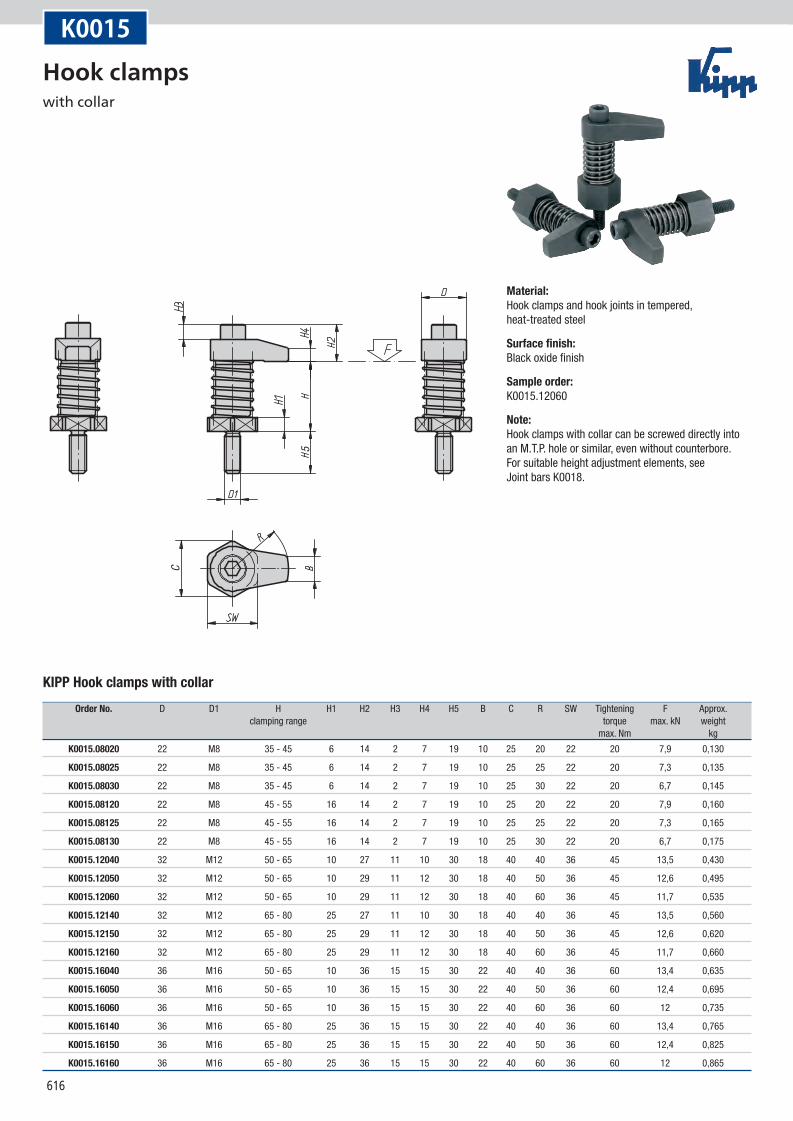
K0015
KIPP Hook clamps with collar
Order No. D D1 H H1 H2 H3 H4 H5 B C R SW Tightening F Approx. clamping range torque max. kN weight max. Nm kg
K0015.08020 22 M8 35 - 45 6 14 2 7 19 10 25 20 22 20 7,9 0,130
K0015.08025 22 M8 35 - 45 6 14 2 7 19 10 25 25 22 20 7,3 0,135
K0015.08030 22 M8 35 - 45 6 14 2 7 19 10 25 30 22 20 6,7 0,145
K0015.08120 22 M8 45 - 55 16 14 2 7 19 10 25 20 22 20 7,9 0,160
K0015.08125 22 M8 45 - 55 16 14 2 7 19 10 25 25 22 20 7,3 0,165
K0015.08130 22 M8 45 - 55 16 14 2 7 19 10 25 30 22 20 6,7 0,175
K0015.12040 32 M12 50 - 65 10 27 11 10 30 18 40 40 36 45 13,5 0,430
K0015.12050 32 M12 50 - 65 10 29 11 12 30 18 40 50 36 45 12,6 0,495
K0015.12060 32 M12 50 - 65 10 29 11 12 30 18 40 60 36 45 11,7 0,535
K0015.12140 32 M12 65 - 80 25 27 11 10 30 18 40 40 36 45 13,5 0,560
K0015.12150 32 M12 65 - 80 25 29 11 12 30 18 40 50 36 45 12,6 0,620
K0015.12160 32 M12 65 - 80 25 29 11 12 30 18 40 60 36 45 11,7 0,660
K0015.16040 36 M16 50 - 65 10 36 15 15 30 22 40 40 36 60 13,4 0,635
K0015.16050 36 M16 50 - 65 10 36 15 15 30 22 40 50 36 60 12,4 0,695
K0015.16060 36 M16 50 - 65 10 36 15 15 30 22 40 60 36 60 12 0,735
K0015.16140 36 M16 65 - 80 25 36 15 15 30 22 40 40 36 60 13,4 0,765
K0015.16150 36 M16 65 - 80 25 36 15 15 30 22 40 50 36 60 12,4 0,825
K0015.16160 36 M16 65 - 80 25 36 15 15 30 22 40 60 36 60 12 0,865
Material:Hook clamps and hook joints in tempered, heat-treated steel
Surface finish:Black oxide finish
Sample order:K0015.12060
Note:Hook clamps with collar can be screwed directly into an M.T.P. hole or similar, even without counterbore. For suitable height adjustment elements, see Joint bars K0018.
Hook clamps with collar
617
D1
B1
B2
B3
B
S H3
H2
H1
H
B4
B5x4
5°
M
D
SW
M
F
A
L
D2 H8
D3
example:
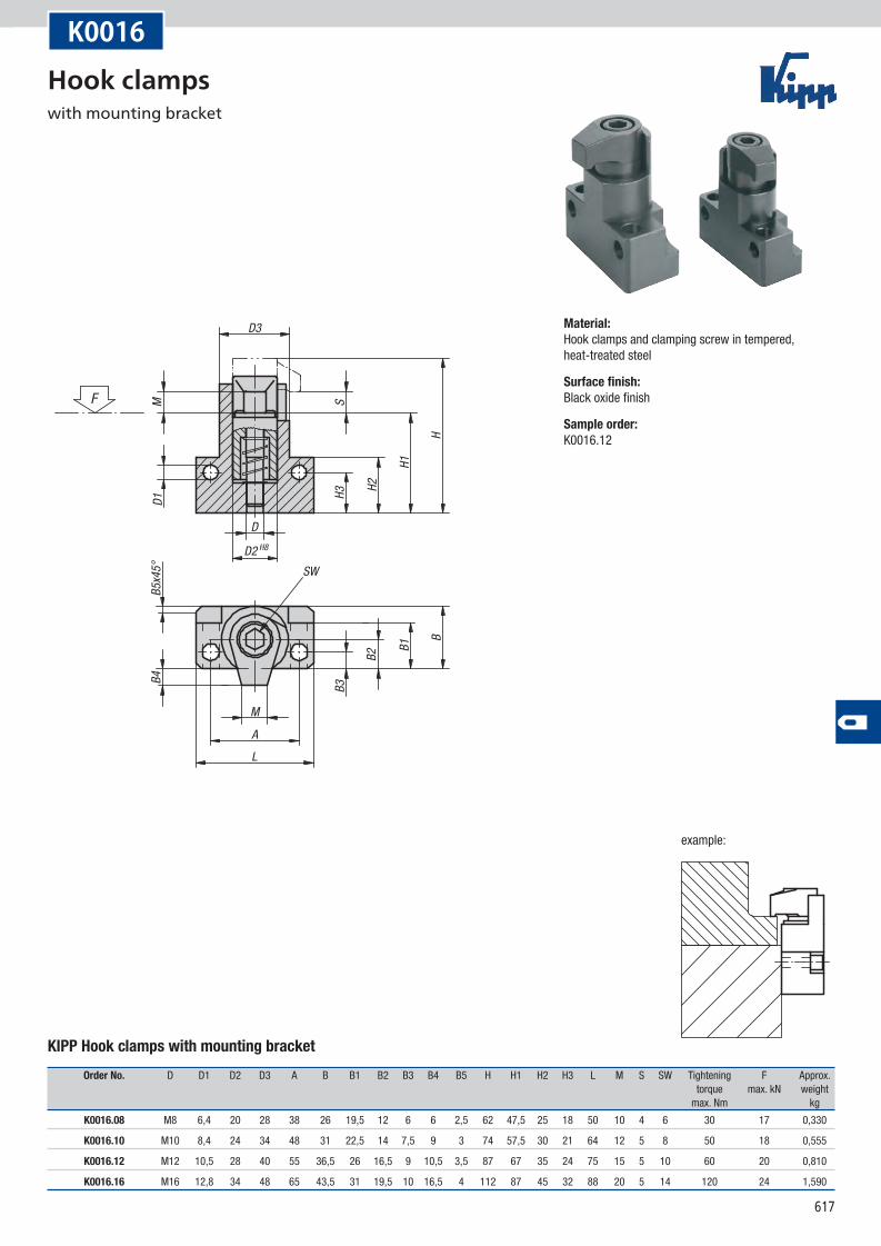
K0016
KIPP Hook clamps with mounting bracket
Order No. D D1 D2 D3 A B B1 B2 B3 B4 B5 H H1 H2 H3 L M S SW Tightening F Approx. torque max. kN weight max. Nm kg
K0016.08 M8 6,4 20 28 38 26 19,5 12 6 6 2,5 62 47,5 25 18 50 10 4 6 30 17 0,330
K0016.10 M10 8,4 24 34 48 31 22,5 14 7,5 9 3 74 57,5 30 21 64 12 5 8 50 18 0,555
K0016.12 M12 10,5 28 40 55 36,5 26 16,5 9 10,5 3,5 87 67 35 24 75 15 5 10 60 20 0,810
K0016.16 M16 12,8 34 48 65 43,5 31 19,5 10 16,5 4 112 87 45 32 88 20 5 14 120 24 1,590
Material:Hook clamps and clamping screw in tempered, heat-treated steel
Surface finish:Black oxide finish
Sample order:K0016.12
Hook clamps with mounting bracket
618
D F7
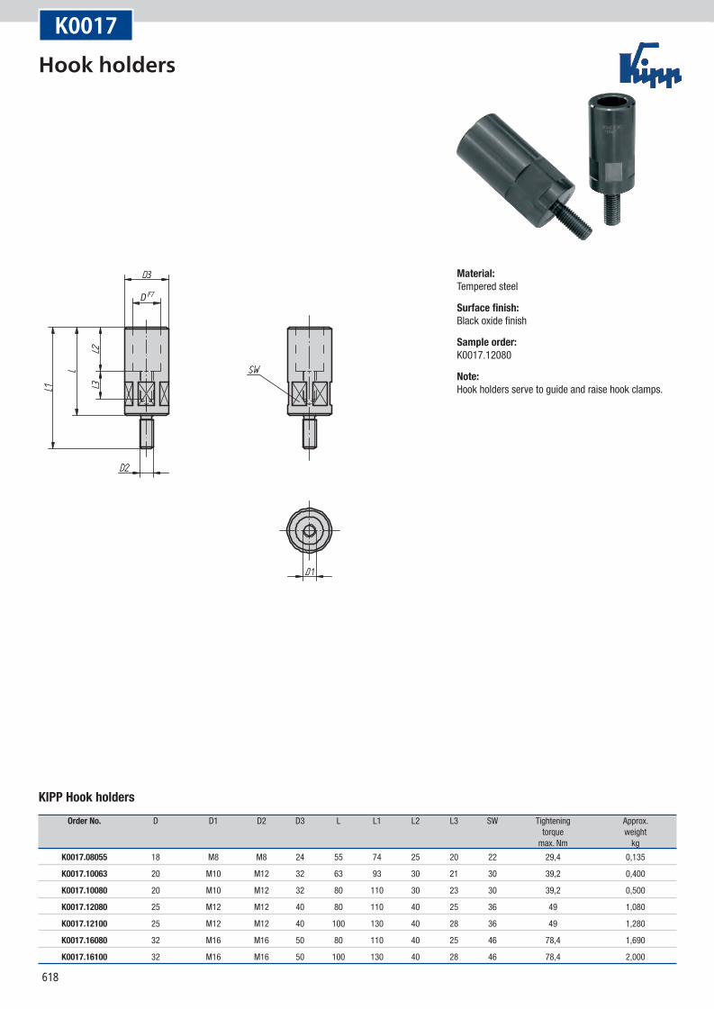
K0017
KIPP Hook holders
Order No. D D1 D2 D3 L L1 L2 L3 SW Tightening Approx. torque weight max. Nm kg
K0017.08055 18 M8 M8 24 55 74 25 20 22 29,4 0,135
K0017.10063 20 M10 M12 32 63 93 30 21 30 39,2 0,400
K0017.10080 20 M10 M12 32 80 110 30 23 30 39,2 0,500
K0017.12080 25 M12 M12 40 80 110 40 25 36 49 1,080
K0017.12100 25 M12 M12 40 100 130 40 28 36 49 1,280
K0017.16080 32 M16 M16 50 80 110 40 25 46 78,4 1,690
K0017.16100 32 M16 M16 50 100 130 40 28 46 78,4 2,000
Material:Tempered steel
Surface finish:Black oxide finish
Sample order:K0017.12080
Note:Hook holders serve to guide and raise hook clamps.
Hook holders
619
K0018
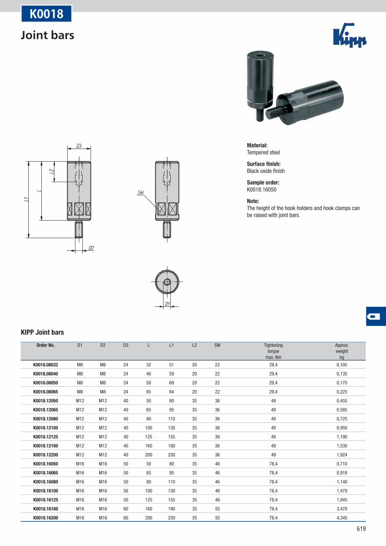
KIPP Joint bars
Order No. D1 D2 D3 L L1 L2 SW Tightening Approx. torque weight max. Nm kg
K0018.08032 M8 M8 24 32 51 20 22 29,4 0,105
K0018.08040 M8 M8 24 40 59 20 22 29,4 0,135
K0018.08050 M8 M8 24 50 69 20 22 29,4 0,170
K0018.08065 M8 M8 24 65 84 20 22 29,4 0,225
K0018.12050 M12 M12 40 50 80 35 36 49 0,455
K0018.12065 M12 M12 40 65 95 35 36 49 0,585
K0018.12080 M12 M12 40 80 110 35 36 49 0,725
K0018.12100 M12 M12 40 100 130 35 36 49 0,950
K0018.12125 M12 M12 40 125 155 35 36 49 1,190
K0018.12160 M12 M12 40 160 190 35 36 49 1,530
K0018.12200 M12 M12 40 200 230 35 36 49 1,924
K0018.16050 M16 M16 50 50 80 35 46 78,4 0,710
K0018.16065 M16 M16 50 65 95 35 46 78,4 0,918
K0018.16080 M16 M16 50 80 110 35 46 78,4 1,140
K0018.16100 M16 M16 50 100 130 35 46 78,4 1,470
K0018.16125 M16 M16 50 125 155 35 46 78,4 1,845
K0018.16160 M16 M16 60 160 190 35 55 78,4 3,470
K0018.16200 M16 M16 60 200 230 35 55 78,4 4,345
Material:Tempered steel
Surface finish:Black oxide finish
Sample order:K0018.16050
Note:The height of the hook holders and hook clamps can be raised with joint bars.
Joint bars
620
appr
ox. 2
512
5 m
ax.
16.5
max
.
example:example:
K0019
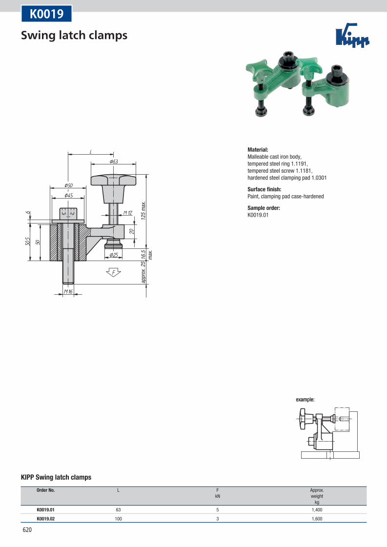
KIPP Swing latch clamps
Order No. L F Approx. kN weight kg
K0019.01 63 5 1,400
K0019.02 100 3 1,600
Material:Malleable cast iron body, tempered steel ring 1.1191, tempered steel screw 1.1181, hardened steel clamping pad 1.0301
Surface finish:Paint, clamping pad case-hardened
Sample order:K0019.01
Swing latch clamps
621
Notes
622
clamp traveltravel path
travel path
travel path
start pointright hand type
end point right hand type
start point left hand typeend point
left hand type
self-locking clamp travel
pres
sure
bush
, axia
l mov
emen
t only
drilled throughwith transverse
axis in bore
clamping curve
push pull
View from below
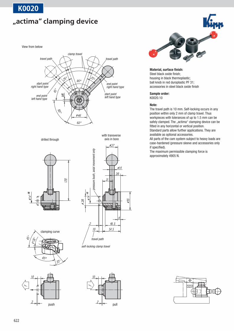
K0020
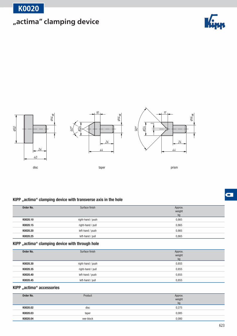
Material, surface finish:Steel black oxide finish; housing in black thermoplastic; ball knob in red duroplastic PF 31; accessories in steel black oxide finish
Sample order:K0020.10
Note:The travel path is 10 mm. Self-locking occurs in any position within only 2 mm of clamp travel. Thus workpieces with tolerances of up to 1.5 mm can be safely clamped. The „actima“ clamping device can be fitted in any horizontal or vertical position. Standard parts allow further applications. They are available as optional accessories. All parts of the cam system subject to heavy loads are case-hardened (pressure sleeve and accessories only if specified). The maximum permissible clamping force is approximately 4905 N.
„actima“ clamping device
623
disc taper prism
K0020
KIPP „actima“ clamping device with transverse axis in the hole
Order No. Surface finish Approx. weight kg
K0020.10 right-hand / push 0,865
K0020.15 right-hand / pull 0,865
K0020.20 left-hand / push 0,865
K0020.25 left-hand / pull 0,865
KIPP „actima“ clamping device with through hole
Order No. Surface finish Approx. weight kg
K0020.30 right-hand / push 0,855
K0020.35 right-hand / pull 0,855
K0020.40 left-hand / push 0,855
K0020.45 left-hand / pull 0,855
KIPP „actima“ accessories
Order No. Product Approx. weight kg
K0020.02 disc 0,275
K0020.03 taper 0,085
K0020.04 vee-block 0,080
„actima“ clamping device
624
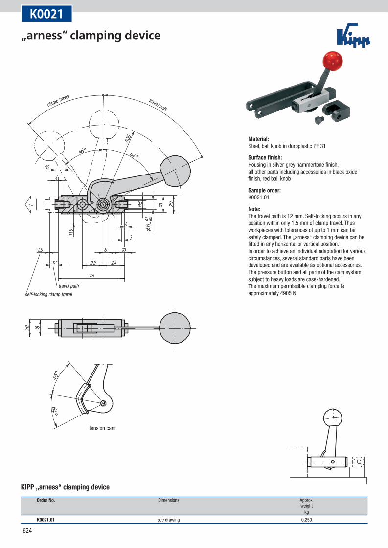
clamp travel travel path
travel pathself-locking clamp travel
tension cam
K0021
Material:Steel, ball knob in duroplastic PF 31
Surface finish:Housing in silver-grey hammertone finish, all other parts including accessories in black oxide finish, red ball knob
Sample order:K0021.01
Note:The travel path is 12 mm. Self-locking occurs in any position within only 1.5 mm of clamp travel. Thus workpieces with tolerances of up to 1 mm can be safely clamped. The „arness“ clamping device can be fitted in any horizontal or vertical position. In order to achieve an individual adaptation for various circumstances, several standard parts have been developed and are available as optional accessories. The pressure button and all parts of the cam system subject to heavy loads are case-hardened. The maximum permissible clamping force is approximately 4905 N.
„arness“ clamping device
KIPP „arness“ clamping device
Order No. Dimensions Approx. weight kg
K0021.01 see drawing 0,250
625
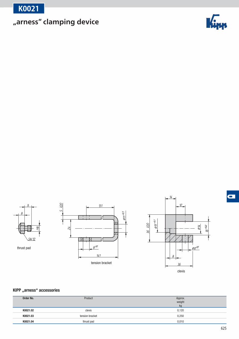
thrust pad
tension bracket
clevis
K0021
KIPP „arness“ accessories
Order No. Product Approx. weight kg
K0021.02 clevis 0,120
K0021.03 tension bracket 0,250
K0021.04 thrust pad 0,010
„arness“ clamping device
626
D
D1
SW
H AL
S1
D1 m
in.
K0022
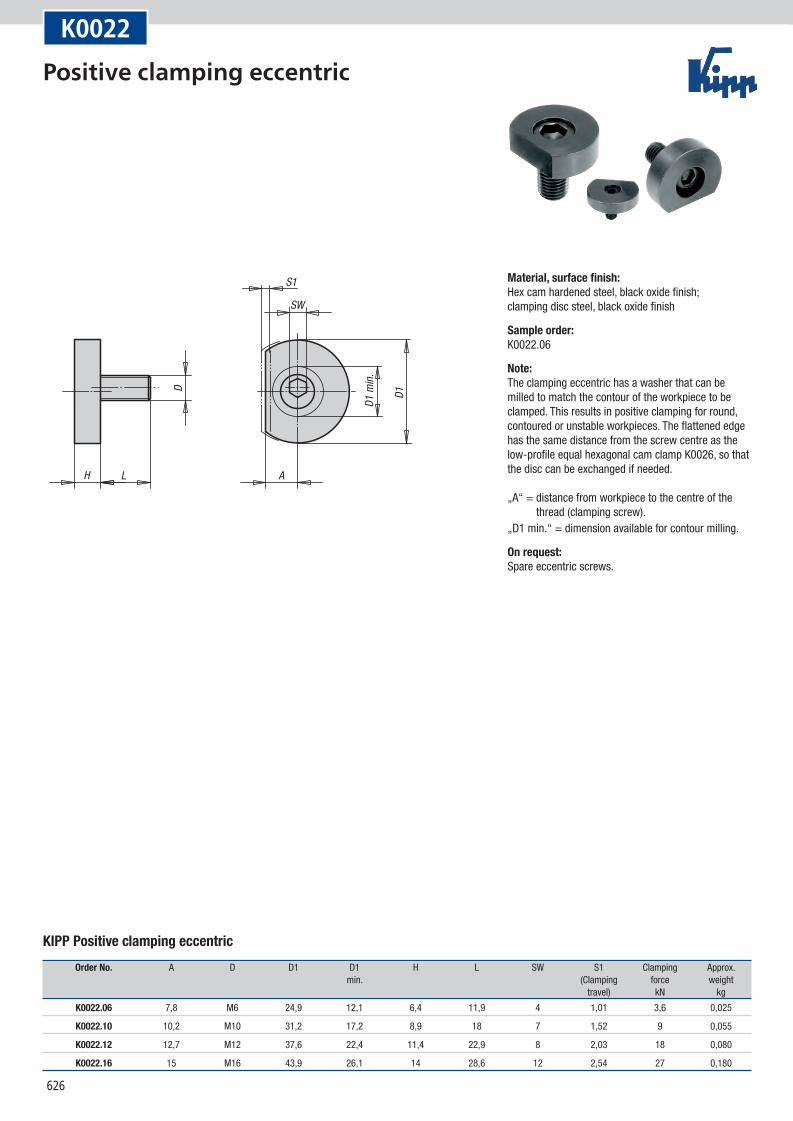
KIPP Positive clamping eccentric
Order No. A D D1 D1 H L SW S1 Clamping Approx. min. (Clamping force weight travel) kN kg
K0022.06 7,8 M6 24,9 12,1 6,4 11,9 4 1,01 3,6 0,025
K0022.10 10,2 M10 31,2 17,2 8,9 18 7 1,52 9 0,055
K0022.12 12,7 M12 37,6 22,4 11,4 22,9 8 2,03 18 0,080
K0022.16 15 M16 43,9 26,1 14 28,6 12 2,54 27 0,180
Material, surface finish:Hex cam hardened steel, black oxide finish; clamping disc steel, black oxide finish
Sample order:K0022.06
Note:The clamping eccentric has a washer that can be milled to match the contour of the workpiece to be clamped. This results in positive clamping for round, contoured or unstable workpieces. The flattened edge has the same distance from the screw centre as the low-profile equal hexagonal cam clamp K0026, so that the disc can be exchanged if needed. „A“ = distance from workpiece to the centre of the
thread (clamping screw).„D1 min.“ = dimension available for contour milling.
On request:Spare eccentric screws.
Positive clamping eccentric
627
D
A
S
H1H
Form Asmooth
Form Btoothed
K0023
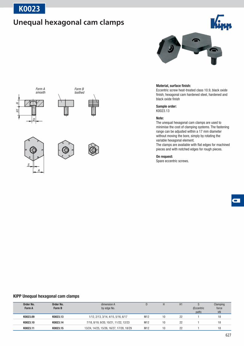
KIPP Unequal hexagonal cam clamps
Order No. Order No. dimension A D H H1 S Clamping Form A Form B by edge No. (Eccentric force path) kN
K0023.09 K0023.13 1/12, 2/13, 3/14, 4/15, 5/16, 6/17 M12 10 22 1 18
K0023.10 K0023.14 7/18, 8/19, 9/20, 10/21, 11/22, 12/23 M12 10 22 1 18
K0023.11 K0023.15 13/24, 14/25, 15/26, 16/27, 17/28, 18/29 M12 10 22 1 18
Material, surface finish:Eccentric screw heat-treated class 10.9, black oxide finish; hexagonal cam hardened steel, hardened and black oxide finish
Sample order:K0023.13
Note:The unequal hexagonal cam clamps are used to minimise the cost of clamping systems. The fastening range can be adjusted within a 17 mm diameter without moving the bore, simply by rotating the variable hexagonal element. The clamps are available with flat edges for machined pieces and with notched edges for rough pieces.
On request:Spare eccentric screws.
Unequal hexagonal cam clamps
628
LH
D
30°
SW
A
A2
A1
S1
X
Z ±0,2
W
mounting dimensions
clamping sheet metal clamping round parts
D1 max.
max
. ½ W
K0024
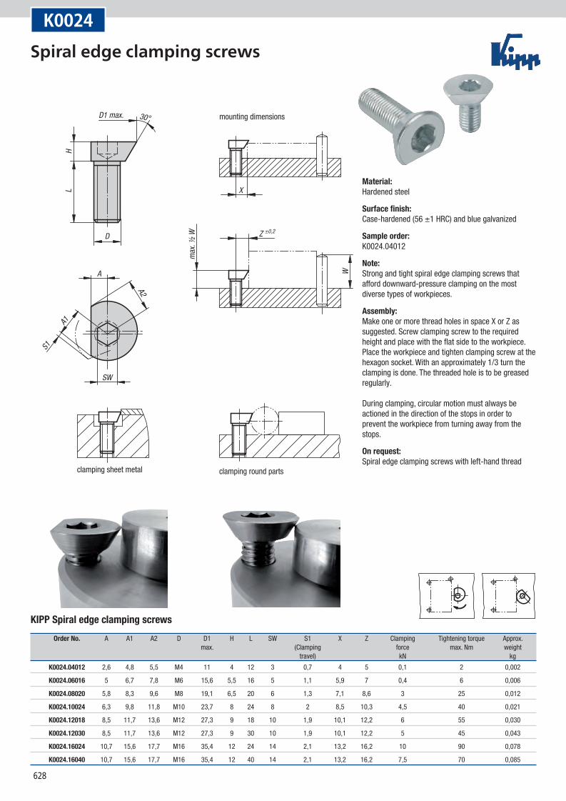
KIPP Spiral edge clamping screws
Order No. A A1 A2 D D1 H L SW S1 X Z Clamping Tightening torque Approx. max. (Clamping force max. Nm weight travel) kN kg
K0024.04012 2,6 4,8 5,5 M4 11 4 12 3 0,7 4 5 0,1 2 0,002
K0024.06016 5 6,7 7,8 M6 15,6 5,5 16 5 1,1 5,9 7 0,4 6 0,006
K0024.08020 5,8 8,3 9,6 M8 19,1 6,5 20 6 1,3 7,1 8,6 3 25 0,012
K0024.10024 6,3 9,8 11,8 M10 23,7 8 24 8 2 8,5 10,3 4,5 40 0,021
K0024.12018 8,5 11,7 13,6 M12 27,3 9 18 10 1,9 10,1 12,2 6 55 0,030
K0024.12030 8,5 11,7 13,6 M12 27,3 9 30 10 1,9 10,1 12,2 5 45 0,043
K0024.16024 10,7 15,6 17,7 M16 35,4 12 24 14 2,1 13,2 16,2 10 90 0,078
K0024.16040 10,7 15,6 17,7 M16 35,4 12 40 14 2,1 13,2 16,2 7,5 70 0,085
Material:Hardened steel
Surface finish:Case-hardened (56 ±1 HRC) and blue galvanized
Sample order:K0024.04012
Note:Strong and tight spiral edge clamping screws that afford downward-pressure clamping on the most diverse types of workpieces.
Assembly:Make one or more thread holes in space X or Z as suggested. Screw clamping screw to the required height and place with the flat side to the workpiece. Place the workpiece and tighten clamping screw at the hexagon socket. With an approximately 1/3 turn the clamping is done. The threaded hole is to be greased regularly. During clamping, circular motion must always be actioned in the direction of the stops in order to prevent the workpiece from turning away from the stops.
On request:Spiral edge clamping screws with left-hand thread
Spiral edge clamping screws
629
K0025
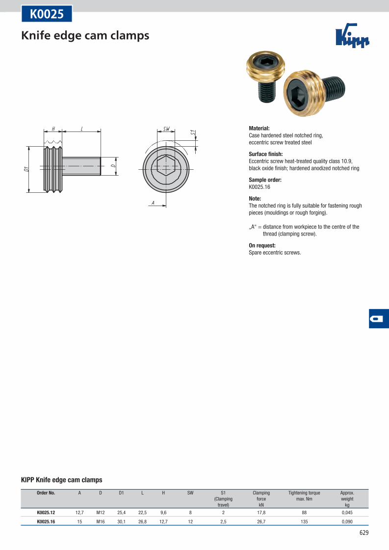
KIPP Knife edge cam clamps
Order No. A D D1 L H SW S1 Clamping Tightening torque Approx. (Clamping force max. Nm weight travel) kN kg
K0025.12 12,7 M12 25,4 22,5 9,6 8 2 17,8 88 0,045
K0025.16 15 M16 30,1 26,8 12,7 12 2,5 26,7 135 0,090
Material:Case hardened steel notched ring, eccentric screw treated steel
Surface finish:Eccentric screw heat-treated quality class 10.9, black oxide finish; hardened anodized notched ring
Sample order:K0025.16
Note:The notched ring is fully suitable for fastening rough pieces (mouldings or rough forging). „A“ = distance from workpiece to the centre of the
thread (clamping screw).
On request:Spare eccentric screws.
Knife edge cam clamps
630
SW ±0,1
SW1S1
DL
H
A
K0026
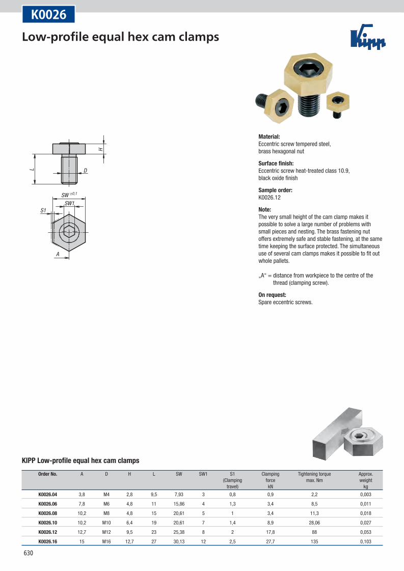
KIPP Low-profile equal hex cam clamps
Order No. A D H L SW SW1 S1 Clamping Tightening torque Approx. (Clamping force max. Nm weight travel) kN kg
K0026.04 3,8 M4 2,8 9,5 7,93 3 0,8 0,9 2,2 0,003
K0026.06 7,8 M6 4,8 11 15,86 4 1,3 3,4 8,5 0,011
K0026.08 10,2 M8 4,8 15 20,61 5 1 3,4 11,3 0,018
K0026.10 10,2 M10 6,4 19 20,61 7 1,4 8,9 28,06 0,027
K0026.12 12,7 M12 9,5 23 25,38 8 2 17,8 88 0,053
K0026.16 15 M16 12,7 27 30,13 12 2,5 27,7 135 0,103
Material:Eccentric screw tempered steel, brass hexagonal nut
Surface finish:Eccentric screw heat-treated class 10.9, black oxide finish
Sample order:K0026.12
Note:The very small height of the cam clamp makes it possible to solve a large number of problems with small pieces and nesting. The brass fastening nut offers extremely safe and stable fastening, at the same time keeping the surface protected. The simultaneous use of several cam clamps makes it possible to fit out whole pallets. „A“ = distance from workpiece to the centre of the
thread (clamping screw).
On request:Spare eccentric screws.
Low-profile equal hex cam clamps
631
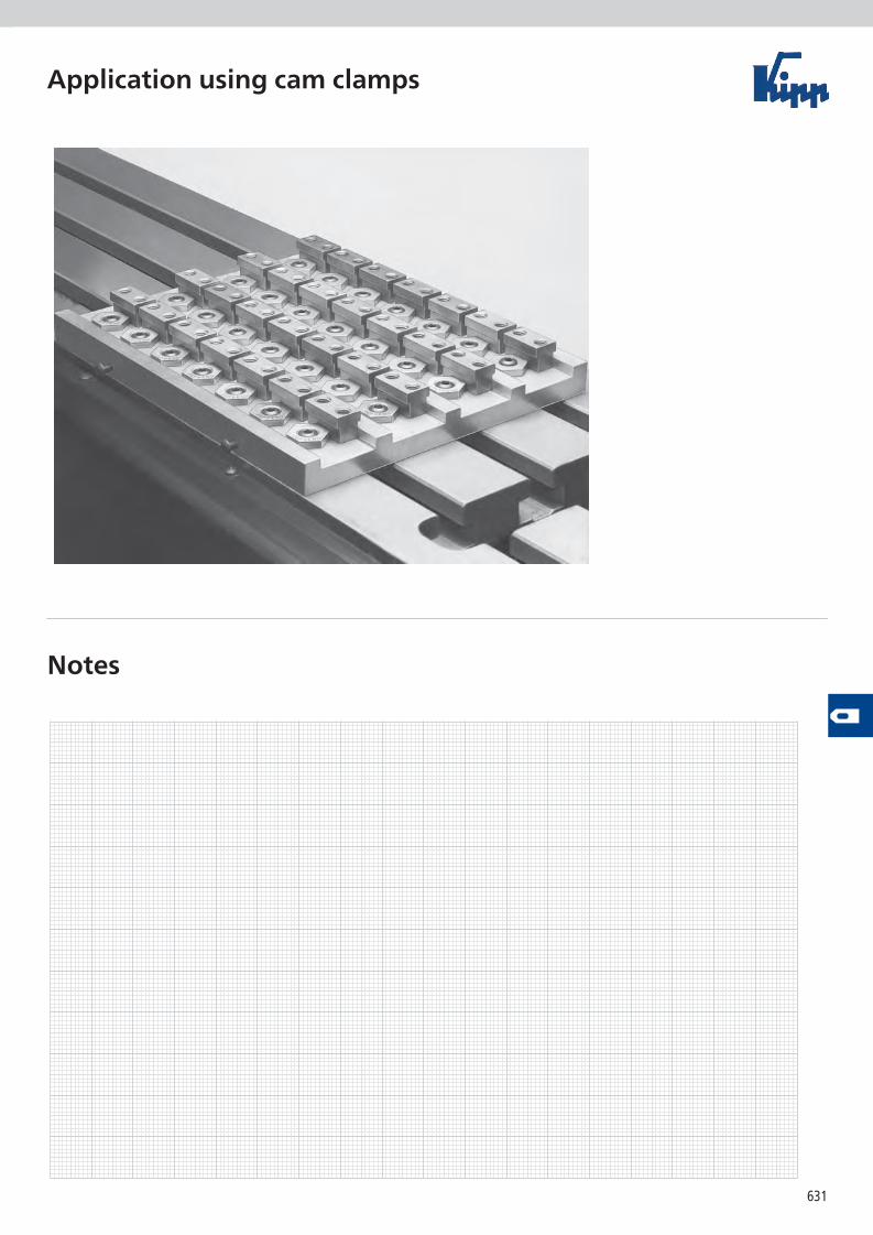
Application using cam clamps
Notes
632
H1
H
H2
D
SW
N
L
S1
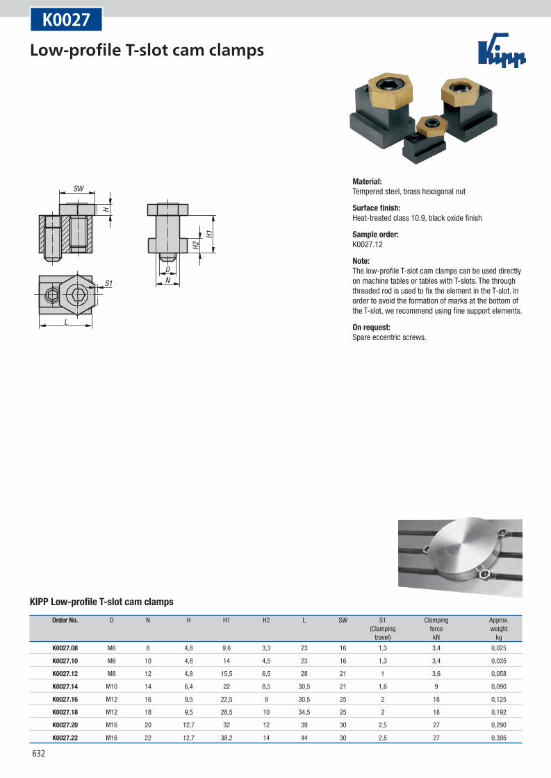
K0027
KIPP Low-profile T-slot cam clamps
Order No. D N H H1 H2 L SW S1 Clamping Approx. (Clamping force weight travel) kN kg
K0027.08 M6 8 4,8 9,6 3,3 23 16 1,3 3,4 0,025
K0027.10 M6 10 4,8 14 4,5 23 16 1,3 3,4 0,035
K0027.12 M8 12 4,8 15,5 6,5 28 21 1 3,6 0,058
K0027.14 M10 14 6,4 22 8,5 30,5 21 1,6 9 0,090
K0027.16 M12 16 9,5 22,5 9 30,5 25 2 18 0,125
K0027.18 M12 18 9,5 28,5 10 34,5 25 2 18 0,192
K0027.20 M16 20 12,7 32 12 39 30 2,5 27 0,290
K0027.22 M16 22 12,7 38,2 14 44 30 2,5 27 0,395
Material:Tempered steel, brass hexagonal nut
Surface finish:Heat-treated class 10.9, black oxide finish
Sample order:K0027.12
Note:The low-profile T-slot cam clamps can be used directly on machine tables or tables with T-slots. The through threaded rod is used to fix the element in the T-slot. In order to avoid the formation of marks at the bottom of the T-slot, we recommend using fine support elements.
On request:Spare eccentric screws.
Low-profile T-slot cam clamps
633
12.1
92 -0
.013
15.7
528
.5
6.355
M12
25.5
B
63.5
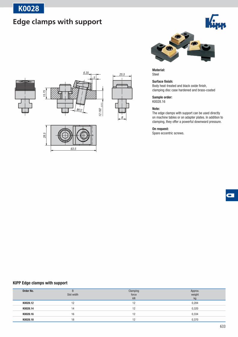
K0028
KIPP Edge clamps with support
Order No. B Clamping Approx. Slot width force weight kN kg
K0028.12 12 12 0,284
K0028.14 14 12 0,320
K0028.16 16 12 0,334
K0028.18 18 12 0,370
Material:Steel
Surface finish:Body heat-treated and black oxide finish, clamping disc case hardened and brass-coated
Sample order:K0028.16
Note:The edge clamps with support can be used directly on machine tables or on adapter plates. In addition to clamping, they offer a powerful downward pressure.
On request:Spare eccentric screws.
Edge clamps with support
634
M12SW 10
53
SW 8
M12
2
50 -1
25.5
B
28.4
16max
. 26
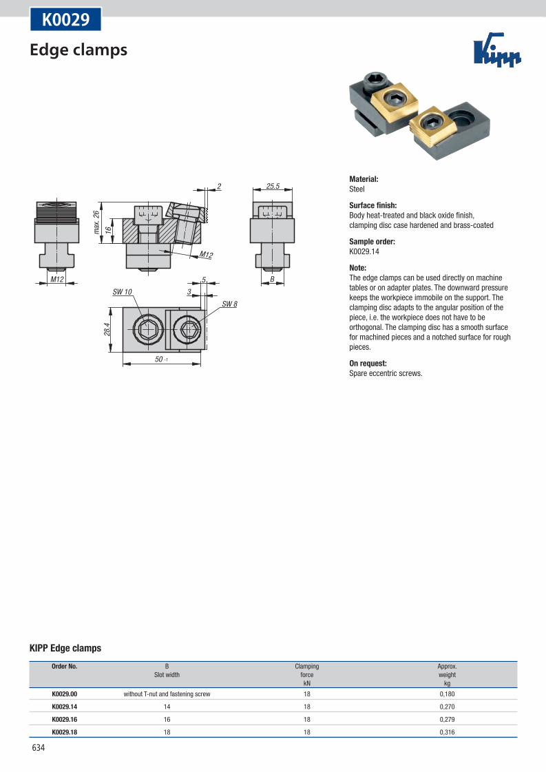
K0029
KIPP Edge clamps
Order No. B Clamping Approx. Slot width force weight kN kg
K0029.00 without T-nut and fastening screw 18 0,180
K0029.14 14 18 0,270
K0029.16 16 18 0,279
K0029.18 18 18 0,316
Material:Steel
Surface finish:Body heat-treated and black oxide finish, clamping disc case hardened and brass-coated
Sample order:K0029.14
Note:The edge clamps can be used directly on machine tables or on adapter plates. The downward pressure keeps the workpiece immobile on the support. The clamping disc adapts to the angular position of the piece, i.e. the workpiece does not have to be orthogonal. The clamping disc has a smooth surface for machined pieces and a notched surface for rough pieces.
On request:Spare eccentric screws.
Edge clamps
635
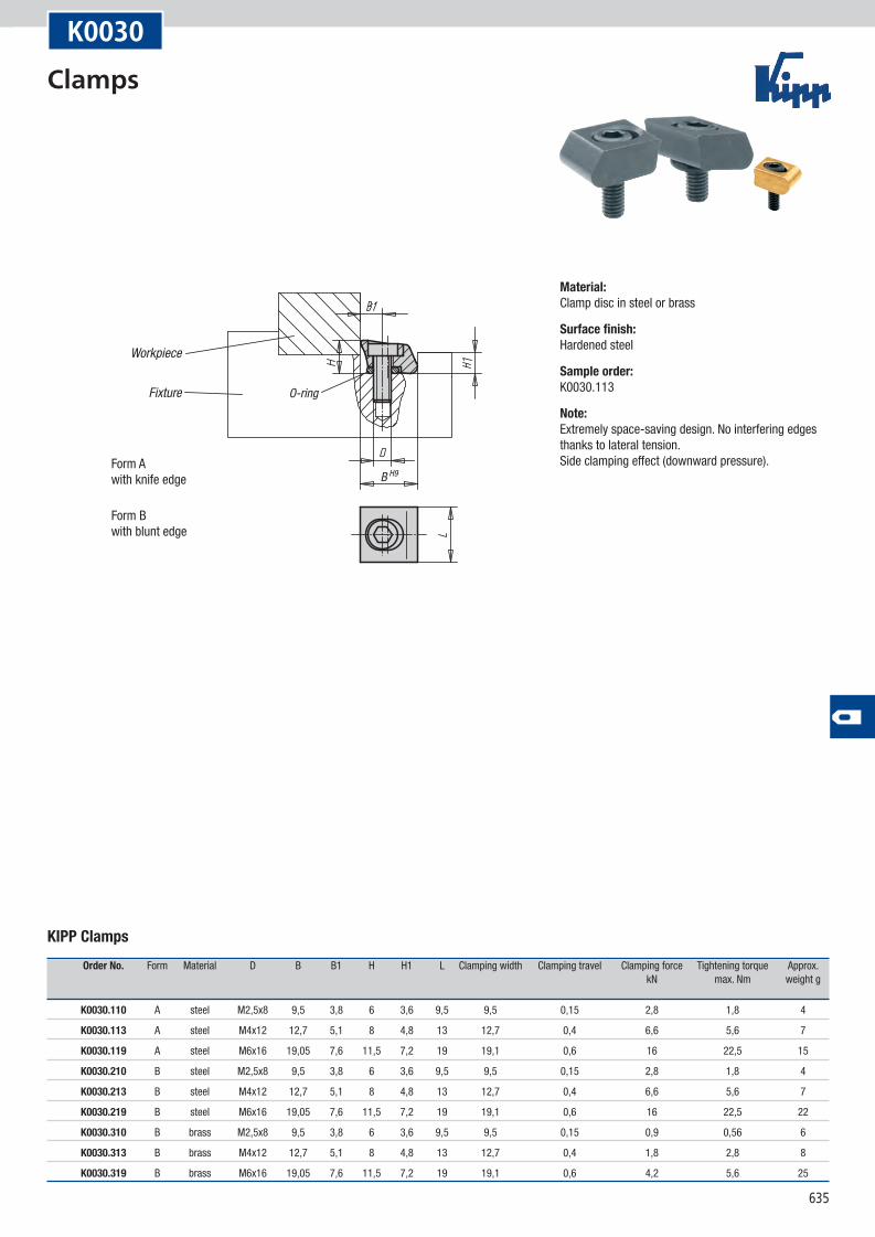
B H9
O-ring
Workpiece
Fixture
Form Awith knife edge
Form Bwith blunt edge
K0030
KIPP Clamps
Order No. Form Material D B B1 H H1 L Clamping width Clamping travel Clamping force Tightening torque Approx. kN max. Nm weight g
K0030.110 A steel M2,5x8 9,5 3,8 6 3,6 9,5 9,5 0,15 2,8 1,8 4
K0030.113 A steel M4x12 12,7 5,1 8 4,8 13 12,7 0,4 6,6 5,6 7
K0030.119 A steel M6x16 19,05 7,6 11,5 7,2 19 19,1 0,6 16 22,5 15
K0030.210 B steel M2,5x8 9,5 3,8 6 3,6 9,5 9,5 0,15 2,8 1,8 4
K0030.213 B steel M4x12 12,7 5,1 8 4,8 13 12,7 0,4 6,6 5,6 7
K0030.219 B steel M6x16 19,05 7,6 11,5 7,2 19 19,1 0,6 16 22,5 22
K0030.310 B brass M2,5x8 9,5 3,8 6 3,6 9,5 9,5 0,15 0,9 0,56 6
K0030.313 B brass M4x12 12,7 5,1 8 4,8 13 12,7 0,4 1,8 2,8 8
K0030.319 B brass M6x16 19,05 7,6 11,5 7,2 19 19,1 0,6 4,2 5,6 25
Material:Clamp disc in steel or brass
Surface finish:Hardened steel
Sample order:K0030.113
Note:Extremely space-saving design. No interfering edges thanks to lateral tension. Side clamping effect (downward pressure).
Clamps
636
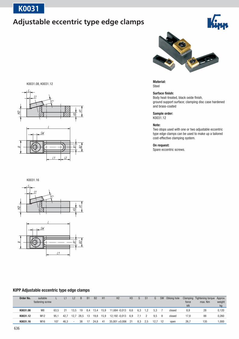
K0031.08, K0031.12
K0031.16
H2H2
K0031
KIPP Adjustable eccentric type edge clamps
Order No. suitable L L1 L2 B B1 B2 H1 H2 H3 S S1 G SW Oblong hole Clamping Tightening torque Approx. fastening screw force max. Nm weight kN kg
K0031.08 M8 63,5 21 13,5 19 8,4 13,4 15,9 11,684 -0,013 6,6 6,3 1,2 5,3 7 closed 8,9 28 0,120
K0031.12 M12 95,1 42,7 12,7 28,5 13 19,8 15,9 12,192 -0,013 6,9 7,1 2 9,5 8 closed 17,8 88 0,260
K0031.16 M16 107 46,3 - 38 17 24,8 41 35,001 ±0,006 21 8,3 2,5 12,7 12 open 26,7 135 1,000
Material:Steel
Surface finish:Body heat-treated, black oxide finish, ground support surface; clamping disc case hardened and brass-coated
Sample order:K0031.12
Note:Two stops used with one or two adjustable eccentric type edge clamps can be used to make up a tailored cost-effective clamping system.
On request:Spare eccentric screws.
Adjustable eccentric type edge clamps
637
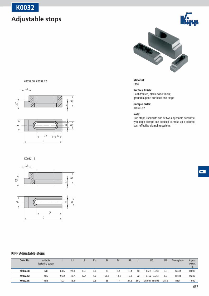
K0032.16
K0032.08, K0032.12
H2H2
K0032
KIPP Adjustable stops
Order No. suitable L L1 L2 L3 B B1 B2 H1 H2 H3 Oblong hole Approx. fastening screw weight kg
K0032.08 M8 63,5 28,3 13,5 7,9 19 8,4 13,4 19 11,684 -0,013 6,6 closed 0,090
K0032.12 M12 95,2 42,7 12,7 7,9 28,5 13,4 19,8 22 12,192 -0,013 6,9 closed 0,280
K0032.16 M16 107 46,2 - 9,5 38 17 24,8 50,7 35,001 ±0,006 21,3 open 1,000
Material:Steel
Surface finish:Heat-treated, black oxide finish; ground support surfaces and stops
Sample order:K0032.12
Note:Two stops used with one or two adjustable eccentric type edge clamps can be used to make up a tailored cost-effective clamping system.
Adjustable stops
638
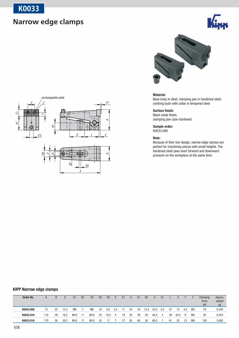
D4
D5
exchangeable plate
K0033
KIPP Narrow edge clamps
Order No. A B D D1 D2 D3 D4 D5 E E1 H H1 H2 K K1 L X Y Z Clamping Approx. force weight kN kg
K0033.006 73 25 12,2 M6 7 M6 16 6,5 2,5 11 35 24 12,4 25,5 2,5 27 12 4,5 M3 10 0,240
K0033.010 110 39 18,2 M10 11 M10 24 10,5 4 18 56 38 20 40,5 4 39 20,5 8 M5 40 0,970
K0033.016 170 58 26,2 M16 17 M10 35 17 7 27 85 60 30 60,5 7 61 32 13 M8 100 3,800
Material:Base body in steel; clamping jaw in hardened steel; centring bush with collar in tempered steel
Surface finish:Black oxide finish; clamping jaw case-hardened
Sample order:K0033.006
Note:Because of their low design, narrow edge clamps are perfect for machining pieces with small heights. The hardened steel jaws exert forward and downward pressure on the workpiece at the same time.
Narrow edge clamps
639
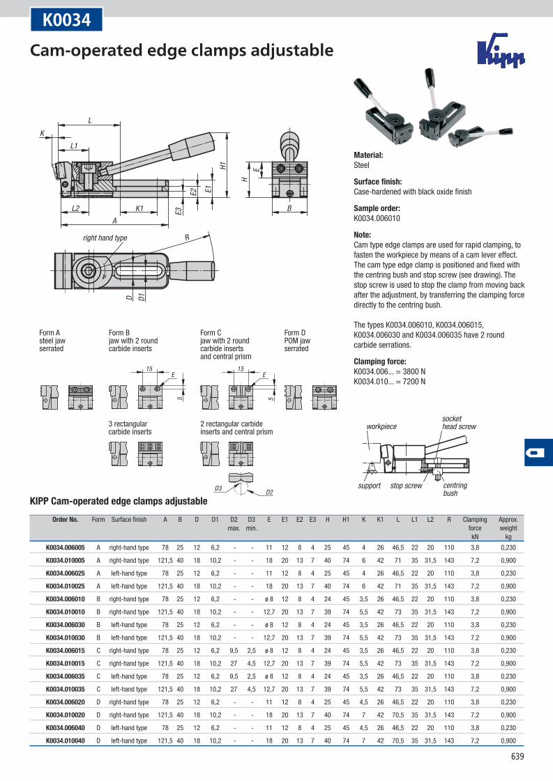
15E
5
15
D3 D2
E
5
R
B
H
H1
E1E2
E3
E
KL
D1D
L1
L2 K1A
right hand type
Form Asteel jawserrated
Form B jaw with 2 round carbide inserts
Form Cjaw with 2 roundcarbide inserts and central prism
Form DPOM jawserrated
3 rectangular carbide inserts
2 rectangular carbide inserts and central prism
stop screw
workpiece
centringbush
socket head screw
support
K0034
KIPP Cam-operated edge clamps adjustable
Order No. Form Surface finish A B D D1 D2 D3 E E1 E2 E3 H H1 K K1 L L1 L2 R Clamping Approx. max. min. force weight kN kg
K0034.006005 A right-hand type 78 25 12 6,2 - - 11 12 8 4 25 45 4 26 46,5 22 20 110 3,8 0,230
K0034.010005 A right-hand type 121,5 40 18 10,2 - - 18 20 13 7 40 74 6 42 71 35 31,5 143 7,2 0,900
K0034.006025 A left-hand type 78 25 12 6,2 - - 11 12 8 4 25 45 4 26 46,5 22 20 110 3,8 0,230
K0034.010025 A left-hand type 121,5 40 18 10,2 - - 18 20 13 7 40 74 6 42 71 35 31,5 143 7,2 0,900
K0034.006010 B right-hand type 78 25 12 6,2 - - ø 8 12 8 4 24 45 3,5 26 46,5 22 20 110 3,8 0,230
K0034.010010 B right-hand type 121,5 40 18 10,2 - - 12,7 20 13 7 39 74 5,5 42 73 35 31,5 143 7,2 0,900
K0034.006030 B left-hand type 78 25 12 6,2 - - ø 8 12 8 4 24 45 3,5 26 46,5 22 20 110 3,8 0,230
K0034.010030 B left-hand type 121,5 40 18 10,2 - - 12,7 20 13 7 39 74 5,5 42 73 35 31,5 143 7,2 0,900
K0034.006015 C right-hand type 78 25 12 6,2 9,5 2,5 ø 8 12 8 4 24 45 3,5 26 46,5 22 20 110 3,8 0,230
K0034.010015 C right-hand type 121,5 40 18 10,2 27 4,5 12,7 20 13 7 39 74 5,5 42 73 35 31,5 143 7,2 0,900
K0034.006035 C left-hand type 78 25 12 6,2 9,5 2,5 ø 8 12 8 4 24 45 3,5 26 46,5 22 20 110 3,8 0,230
K0034.010035 C left-hand type 121,5 40 18 10,2 27 4,5 12,7 20 13 7 39 74 5,5 42 73 35 31,5 143 7,2 0,900
K0034.006020 D right-hand type 78 25 12 6,2 - - 11 12 8 4 25 45 4,5 26 46,5 22 20 110 3,8 0,230
K0034.010020 D right-hand type 121,5 40 18 10,2 - - 18 20 13 7 40 74 7 42 70,5 35 31,5 143 7,2 0,900
K0034.006040 D left-hand type 78 25 12 6,2 - - 11 12 8 4 25 45 4,5 26 46,5 22 20 110 3,8 0,230
K0034.010040 D left-hand type 121,5 40 18 10,2 - - 18 20 13 7 40 74 7 42 70,5 35 31,5 143 7,2 0,900
Material:Steel
Surface finish:Case-hardened with black oxide finish
Sample order:K0034.006010
Note:Cam type edge clamps are used for rapid clamping, to fasten the workpiece by means of a cam lever effect. The cam type edge clamp is positioned and fixed with the centring bush and stop screw (see drawing). The stop screw is used to stop the clamp from moving back after the adjustment, by transferring the clamping force directly to the centring bush. The types K0034.006010, K0034.006015, K0034.006030 and K0034.006035 have 2 round carbide serrations.
Clamping force:K0034.006... = 3800 N K0034.010... = 7200 N
Cam-operated edge clamps adjustable
640
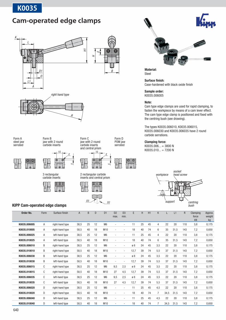
15E
5
15
D3 D2
E
5
R
B
H
H1 E
KL
D1D
L1A
right hand type
Form Asteel jawserrated
Form Bjaw with 2 roundcarbide inserts
Form Cjaw with 2 roundcarbide inserts and central prism
Form DPOM jaw serrated
3 rectangular carbide inserts
2 rectangular carbide inserts and central prism
workpiecesockethead screw
centringbush
support
K0035
KIPP Cam-operated edge clamps
Order No. Form Surface finish A B D D1 D2 D3 E H H1 K L L1 R Clamping Approx. max. min. force weight kN kg
K0035.006005 A right-hand type 38,5 25 12 M6 - - 11 25 45 4 22 20 110 3,8 0,175
K0035.010005 A right-hand type 58,5 40 18 M10 - - 18 40 74 6 35 31,5 143 7,2 0,650
K0035.006025 A left-hand type 38,5 25 12 M6 - - 11 25 45 4 22 20 110 3,8 0,175
K0035.010025 A left-hand type 58,5 40 18 M10 - - 18 40 74 6 35 31,5 143 7,2 0,650
K0035.006010 B right-hand type 38,5 25 12 M6 - - ø 8 24 45 3,5 22 20 110 3,8 0,175
K0035.010010 B right-hand type 58,5 40 18 M10 - - 12,7 39 74 5,5 37 31,5 143 7,2 0,650
K0035.006030 B left-hand type 38,5 25 12 M6 - - ø 8 24 45 3,5 22 20 110 3,8 0,175
K0035.010030 B left-hand type 58,5 40 18 M10 - - 12,7 39 74 5,5 37 31,5 143 7,2 0,650
K0035.006015 C right-hand type 38,5 25 12 M6 9,5 2,5 ø 8 24 45 3,5 22 20 110 3,8 0,175
K0035.010015 C right-hand type 58,5 40 18 M10 27 4,5 12,7 39 74 5,5 37 31,5 143 7,2 0,650
K0035.006035 C left-hand type 38,5 25 12 M6 9,5 2,5 ø 8 24 45 3,5 22 20 110 3,8 0,175
K0035.010035 C left-hand type 58,5 40 18 M10 27 4,5 12,7 39 74 5,5 37 31,5 143 7,2 0,650
K0035.006020 D right-hand type 38,5 25 12 M6 - - 11 25 45 4,5 22 20 110 3,8 0,175
K0035.010020 D right-hand type 58,5 40 18 M10 - - 18 40 74 7 34,5 31,5 143 7,2 0,650
K0035.006040 D left-hand type 38,5 25 12 M6 - - 11 25 45 4,5 22 20 110 3,8 0,175
K0035.010040 D left-hand type 58,5 40 18 M10 - - 18 40 74 7 34,5 31,5 143 7,2 0,650
Material:Steel
Surface finish:Case-hardened with black oxide finish
Sample order:K0035.006005
Note:Cam type edge clamps are used for rapid clamping, to fasten the workpiece by means of a cam lever effect. The cam type edge clamp is positioned and fixed with the centring bush (see drawing). The types K0035.006010, K0035.006015, K0035.006030 and K0035.006035 have 2 round carbide serrations.
Clamping force:K0035.006... = 3800 N K0035.010... = 7200 N
Cam-operated edge clamps
641
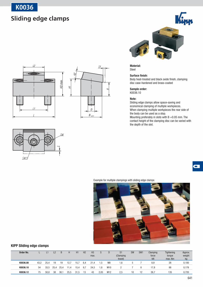
B -0.1
D
H3 m
ax.
Example for multiple clampings with sliding edge clamps
K0036
KIPP Sliding edge clamps
Order No. L L1 L2 B H H1 H2 H3 S D S1 SW SW1 Clamping Tightening Approx. max. (Clamping force torque weight travel) kN max. Nm kg
K0036.08 43,2 25,4 19 19 12,7 15,7 6,4 21,4 1,5 M8 1,6 5 7 8,9 28 0,100
K0036.10 54 33,5 25,4 25,4 11,4 15,4 9,7 24,5 1,8 M10 2 7 8 17,8 88 0,178
K0036.12 75 50,8 38 38,1 25,5 31,5 13 43 2,05 M12 2,5 10 12 26,7 135 0,720
Material:Steel
Surface finish:Body heat-treated and black oxide finish, clamping disc case-hardened and brass-coated
Sample order:K0036.10
Note:Sliding edge clamps allow space-saving and economical clamping of multiple workpieces. When clamping multiple workpieces the rear side of the body can be used as a stop. Mounting preferably in slots with B +0.05 mm. The contact height of the clamping disc can be varied with the depth of the slot.
Sliding edge clamps
642
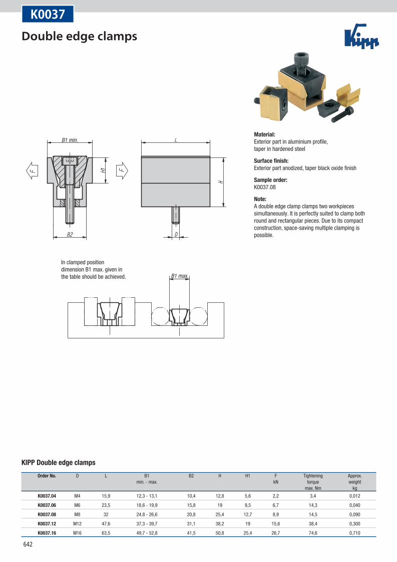
B1 max.
B1 min.
In clamped position dimension B1 max. given in the table should be achieved.
K0037
KIPP Double edge clamps
Order No. D L B1 B2 H H1 F Tightening Approx. min. - max. kN torque weight max. Nm kg
K0037.04 M4 15,9 12,3 - 13,1 10,4 12,8 5,6 2,2 3,4 0,012
K0037.06 M6 23,5 18,6 - 19,9 15,8 19 9,5 6,7 14,3 0,040
K0037.08 M8 32 24,8 - 26,6 20,8 25,4 12,7 8,9 14,5 0,090
K0037.12 M12 47,6 37,3 - 39,7 31,1 38,2 19 15,6 38,4 0,300
K0037.16 M16 63,5 49,7 - 52,8 41,5 50,8 25,4 26,7 74,6 0,710
Material:Exterior part in aluminium profile, taper in hardened steel
Surface finish:Exterior part anodized, taper black oxide finish
Sample order:K0037.08
Note:A double edge clamp clamps two workpieces simultaneously. It is perfectly suited to clamp both round and rectangular pieces. Due to its compact construction, space-saving multiple clamping is possible.
Double edge clamps
643
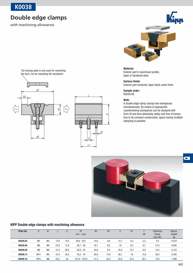
The locking plate is only used for machining the form, not for clampiing the workpiece
K0038
KIPP Double edge clamps with machining allowance
Order No. D D1 L L1 B1 B2 B3 H H1 F Tightening Approx. min. - max. kN torque weight max. Nm kg
K0038.04 M4 M2 15,9 10,2 28,6 - 29,1 10,6 4,6 12,7 6,3 2,2 3,4 0,018
K0038.06 M6 M4 23,9 15,9 38,1 - 39 16,1 6,6 19 9,5 6,7 14,3 0,056
K0038.08 M8 M4 31,8 20,6 50,8 - 52 20,8 9,4 25,4 12,7 8,9 14,5 0,123
K0038.12 M12 M5 47,6 30,5 76,2 - 78 30,9 14,8 38,1 19 15,6 38,4 0,420
K0038.16 M16 M6 63,5 40 101,6 - 103,9 41,3 20,3 50,8 25,4 26,7 74,6 1,008
Material:Exterior part in aluminium profile, taper in hardened steel
Surface finish:Exterior part anodized, taper black oxide finish
Sample order:K0038.08
Note:A double edge clamp clamps two workpieces simultaneously. By means of appropriate countersinking workpieces can be clamped with form-fit and thus absolutely safely and free of torsion. Due to its compact construction, space-saving multiple clamping is possible.
Double edge clamps with machining allowance
644
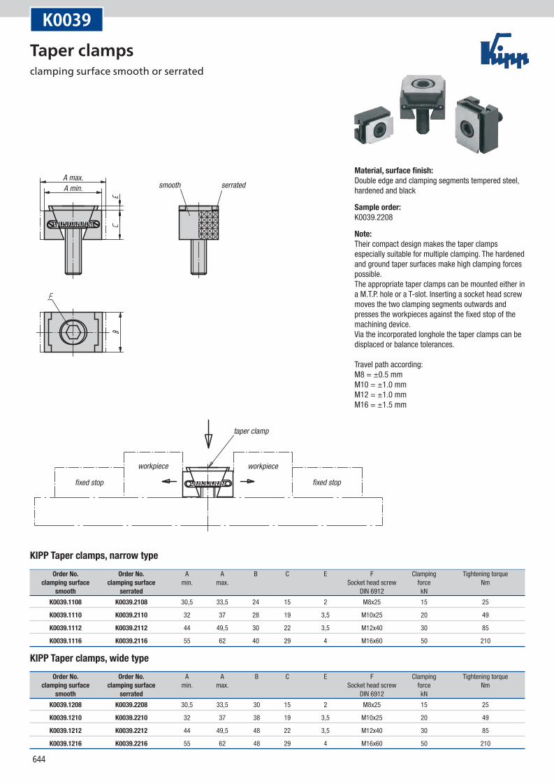
smooth serratedA max.A min.
fixed stop
workpiece
taper clamp
workpiece
fixed stop
K0039
KIPP Taper clamps, narrow type
Order No. Order No. A A B C E F Clamping Tightening torque clamping surface clamping surface min. max. Socket head screw force Nm smooth serrated DIN 6912 kN
K0039.1108 K0039.2108 30,5 33,5 24 15 2 M8x25 15 25
K0039.1110 K0039.2110 32 37 28 19 3,5 M10x25 20 49
K0039.1112 K0039.2112 44 49,5 30 22 3,5 M12x40 30 85
K0039.1116 K0039.2116 55 62 40 29 4 M16x60 50 210
KIPP Taper clamps, wide type
Order No. Order No. A A B C E F Clamping Tightening torque clamping surface clamping surface min. max. Socket head screw force Nm smooth serrated DIN 6912 kN
K0039.1208 K0039.2208 30,5 33,5 30 15 2 M8x25 15 25
K0039.1210 K0039.2210 32 37 38 19 3,5 M10x25 20 49
K0039.1212 K0039.2212 44 49,5 48 22 3,5 M12x40 30 85
K0039.1216 K0039.2216 55 62 48 29 4 M16x60 50 210
Material, surface finish:Double edge and clamping segments tempered steel, hardened and black
Sample order:K0039.2208
Note:Their compact design makes the taper clamps especially suitable for multiple clamping. The hardened and ground taper surfaces make high clamping forces possible. The appropriate taper clamps can be mounted either in a M.T.P. hole or a T-slot. Inserting a socket head screw moves the two clamping segments outwards and presses the workpieces against the fixed stop of the machining device. Via the incorporated longhole the taper clamps can be displaced or balance tolerances. Travel path according: M8 = ±0.5 mm M10 = ±1.0 mm M12 = ±1.0 mm M16 = ±1.5 mm
Taper clamps clamping surface smooth or serrated
645
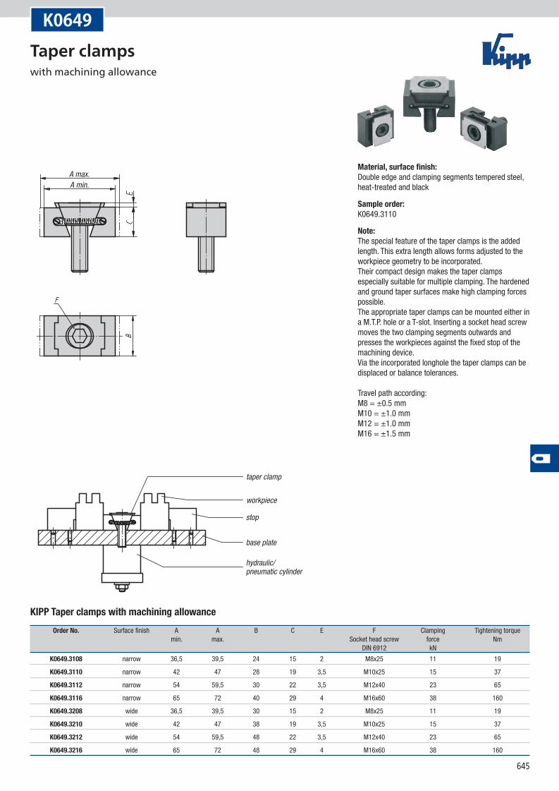
A max.A min.
workpiece
taper clamp
stop
base plate
hydraulic/pneumatic cylinder
K0649
KIPP Taper clamps with machining allowance
Order No. Surface finish A A B C E F Clamping Tightening torque min. max. Socket head screw force Nm DIN 6912 kN
K0649.3108 narrow 36,5 39,5 24 15 2 M8x25 11 19
K0649.3110 narrow 42 47 28 19 3,5 M10x25 15 37
K0649.3112 narrow 54 59,5 30 22 3,5 M12x40 23 65
K0649.3116 narrow 65 72 40 29 4 M16x60 38 160
K0649.3208 wide 36,5 39,5 30 15 2 M8x25 11 19
K0649.3210 wide 42 47 38 19 3,5 M10x25 15 37
K0649.3212 wide 54 59,5 48 22 3,5 M12x40 23 65
K0649.3216 wide 65 72 48 29 4 M16x60 38 160
Material, surface finish:Double edge and clamping segments tempered steel, heat-treated and black
Sample order:K0649.3110
Note:The special feature of the taper clamps is the added length. This extra length allows forms adjusted to the workpiece geometry to be incorporated. Their compact design makes the taper clamps especially suitable for multiple clamping. The hardened and ground taper surfaces make high clamping forces possible. The appropriate taper clamps can be mounted either in a M.T.P. hole or a T-slot. Inserting a socket head screw moves the two clamping segments outwards and presses the workpieces against the fixed stop of the machining device. Via the incorporated longhole the taper clamps can be displaced or balance tolerances. Travel path according: M8 = ±0.5 mm M10 = ±1.0 mm M12 = ±1.0 mm M16 = ±1.5 mm
Taper clamps with machining allowance
646
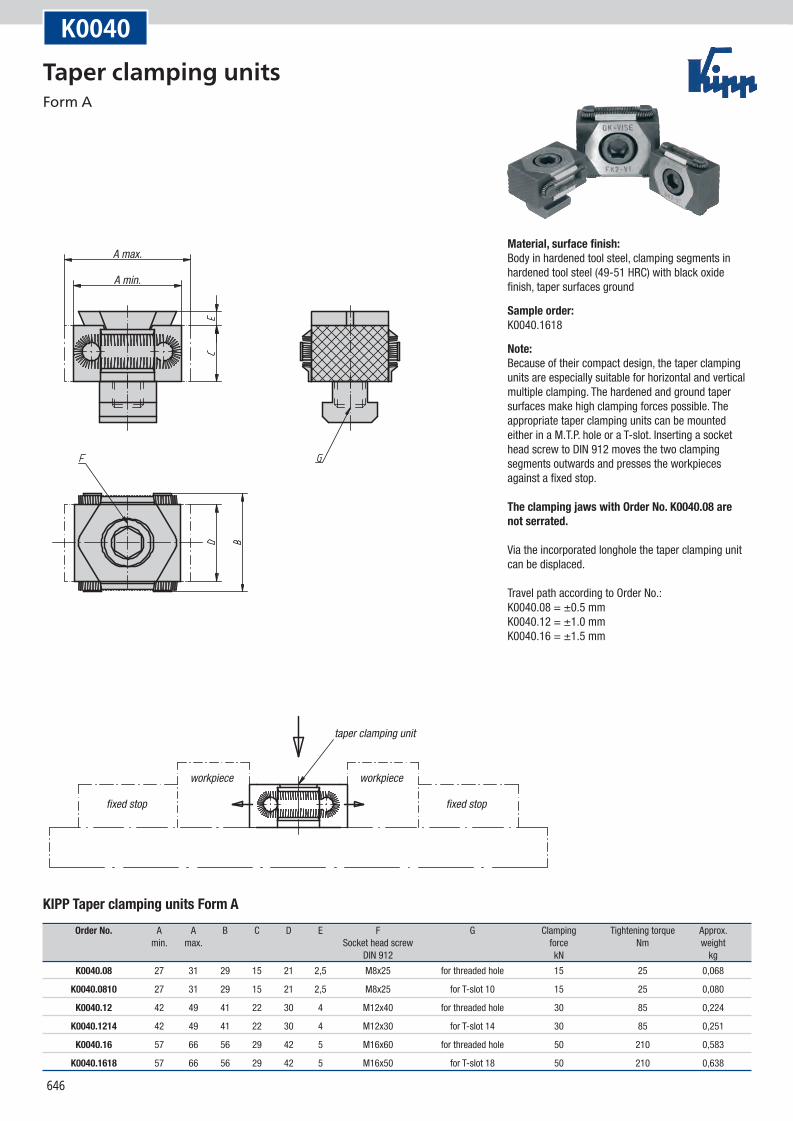
A max.
A min.
fixed stop fixed stop
workpiece workpiece
taper clamping unit
K0040
KIPP Taper clamping units Form A
Order No. A A B C D E F G Clamping Tightening torque Approx. min. max. Socket head screw force Nm weight DIN 912 kN kg
K0040.08 27 31 29 15 21 2,5 M8x25 for threaded hole 15 25 0,068
K0040.0810 27 31 29 15 21 2,5 M8x25 for T-slot 10 15 25 0,080
K0040.12 42 49 41 22 30 4 M12x40 for threaded hole 30 85 0,224
K0040.1214 42 49 41 22 30 4 M12x30 for T-slot 14 30 85 0,251
K0040.16 57 66 56 29 42 5 M16x60 for threaded hole 50 210 0,583
K0040.1618 57 66 56 29 42 5 M16x50 for T-slot 18 50 210 0,638
Material, surface finish:Body in hardened tool steel, clamping segments in hardened tool steel (49-51 HRC) with black oxide finish, taper surfaces ground
Sample order:K0040.1618
Note:Because of their compact design, the taper clamping units are especially suitable for horizontal and vertical multiple clamping. The hardened and ground taper surfaces make high clamping forces possible. The appropriate taper clamping units can be mounted either in a M.T.P. hole or a T-slot. Inserting a socket head screw to DIN 912 moves the two clamping segments outwards and presses the workpieces against a fixed stop. The clamping jaws with Order No. K0040.08 are not serrated. Via the incorporated longhole the taper clamping unit can be displaced. Travel path according to Order No.: K0040.08 = ±0.5 mm K0040.12 = ±1.0 mm K0040.16 = ±1.5 mm
Taper clamping units Form A
647
A max.
A min.
taper clamping unit
workpiece
stop block
base plate
hydraulic/pneumatic cylinder
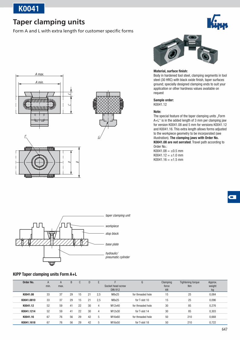
K0041
KIPP Taper clamping units Form A+L
Order No. A A B C D E F G Clamping Tightening torque Approx. min. max. Socket head screw force Nm weight DIN 912 kN kg
K0041.08 33 37 29 15 21 2,5 M8x25 for threaded hole 15 25 0,084
K0041.0810 33 37 29 15 21 2,5 M8x25 for T-slot 10 15 25 0,096
K0041.12 52 59 41 22 30 4 M12x40 for threaded hole 30 85 0,276
K0041.1214 52 59 41 22 30 4 M12x30 for T-slot 14 30 85 0,303
K0041.16 67 76 56 29 42 5 M16x60 for threaded hole 50 210 0,668
K0041.1618 67 76 56 29 42 5 M16x50 for T-slot 18 50 210 0,722
Material, surface finish:Body in hardened tool steel, clamping segments in tool steel (30 HRC) with black oxide finish, taper surfaces ground; specially designed clamping ends to suit your application or other hardness values available on request
Sample order:K0041.12
Note:The special feature of the taper clamping units „Form A+L“ is in the added length of 3 mm per clamping jaw for version K0041.08 and 5 mm for versions K0041.12 and K0041.16. This extra length allows forms adjusted to the workpiece geometry to be incorporated (see illustration). The clamping jaws with Order No. K0041.08 are not serrated. Travel path according to Order No.: K0041.08 = ±0.5 mm K0041.12 = ±1.0 mm K0041.16 = ±1.5 mm
Taper clamping units Form A and L with extra length for customer specific forms
648
A max.
A min.
fixed stop fixed stop
workpiece workpiece
taper clamping unit
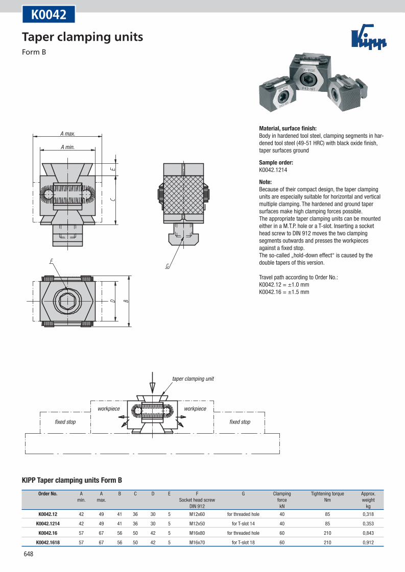
K0042
KIPP Taper clamping units Form B
Order No. A A B C D E F G Clamping Tightening torque Approx. min. max. Socket head screw force Nm weight DIN 912 kN kg
K0042.12 42 49 41 36 30 5 M12x60 for threaded hole 40 85 0,318
K0042.1214 42 49 41 36 30 5 M12x50 for T-slot 14 40 85 0,353
K0042.16 57 67 56 50 42 5 M16x80 for threaded hole 60 210 0,843
K0042.1618 57 67 56 50 42 5 M16x70 for T-slot 18 60 210 0,912
Material, surface finish:Body in hardened tool steel, clamping segments in har-dened tool steel (49-51 HRC) with black oxide finish, taper surfaces ground
Sample order:K0042.1214
Note:Because of their compact design, the taper clamping units are especially suitable for horizontal and vertical multiple clamping. The hardened and ground taper surfaces make high clamping forces possible. The appropriate taper clamping units can be mounted either in a M.T.P. hole or a T-slot. Inserting a socket head screw to DIN 912 moves the two clamping segments outwards and presses the workpieces against a fixed stop. The so-called „hold-down effect“ is caused by the double tapers of this version. Travel path according to Order No.: K0042.12 = ±1.0 mm K0042.16 = ±1.5 mm
Taper clamping units Form B
649
tapered-head bolt
D3for countersunk screw ISO 10642
D min.*
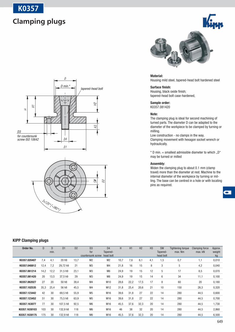
K0357
KIPP Clamping plugs
Order No. D D D1 D2 D3 D4 H H1 H2 H3 SW Tightening torque Clamping force Approx. min. for Tapered- Tapered- max. Nm max. kN weight countersunk screw head bolt head bolt kg
K0357.020407 7,4 4,1 20 h9 13,7 M2 M2 10,7 7,6 6,1 4,1 1,5 0,7 1,1 0,010
K0357.040812 12,4 7,2 29,72 h9 21 M3 M4 21,8 16 15 8 3 5 4,2 0,040
K0357.061214 14,2 12,2 31,5 h9 23,1 M3 M6 24,9 19 15 12 5 17 8,5 0,070
K0357.081420 20 13,5 37,5 h9 29 M3 M8 24,9 19 15 14 6 34 11,1 0,100
K0357.062027 27 20 50 h8 39,4 M4 M10 28,6 22,2 17,5 17 8 60 20 0,180
K0357.102535 35,3 25,4 56 h8 45,5 M4 M12 31,8 25,4 20,6 21 10 150 26,3 0,320
K0357.123442 42 30 69,5 h8 55,9 M5 M16 39,6 31,8 27 22 14 280 44,5 0,600
K0357.123452 51 30 75,5 h8 63,9 M5 M16 39,6 31,8 27 22 14 280 44,5 0,700
K0357.163077 77 30 107,5 h8 92,5 M6 M16 45,5 37,6 32,3 20 14 280 44,5 1,730
K0357.1630103 103 30 132,9 h8 118 M6 M16 46 38 32 20 14 280 44,5 2,860
K0357.1630175 175 30 132,9 h8 118 M6 M16 45,5 37,6 32,3 20 14 280 44,5 6,500
Material:Housing mild steel, tapered-head bolt hardened steel
Surface finish:Housing, black oxide finish; tapered-head bolt case-hardened,
Sample order:K0357.081420
Note:The clamping plug is ideal for second machining of turned parts. The diameter D can be adapted to the diameter of the workpiece to be clamped by turning or milling. Low construction - no clamps in the way. Clamping movement with hexagon socket wrench or hydraulically. * D min. = smallest admissible diameter to which „D“ may be turned or milled
Assembly:Widen the clamping plug to about 0.1 mm (clamp travel) more than the diameter at rest. Machine to the internal diameter of the workpiece by turning or mil-ling. The base can be centred in a hole or with locating pins as required.
Clamping plugs
650
D
SW
H1
D
H2
H
D1 h8
D1 h8
6x60° (=360°)
D4
D2
SW H
H1 H2H3
D min.* D min.*
D3for countersunk screw ISO 10642
Form Afor machining centres,drilling and milling machines
Form Bwith shaft for holding in lathe chucks
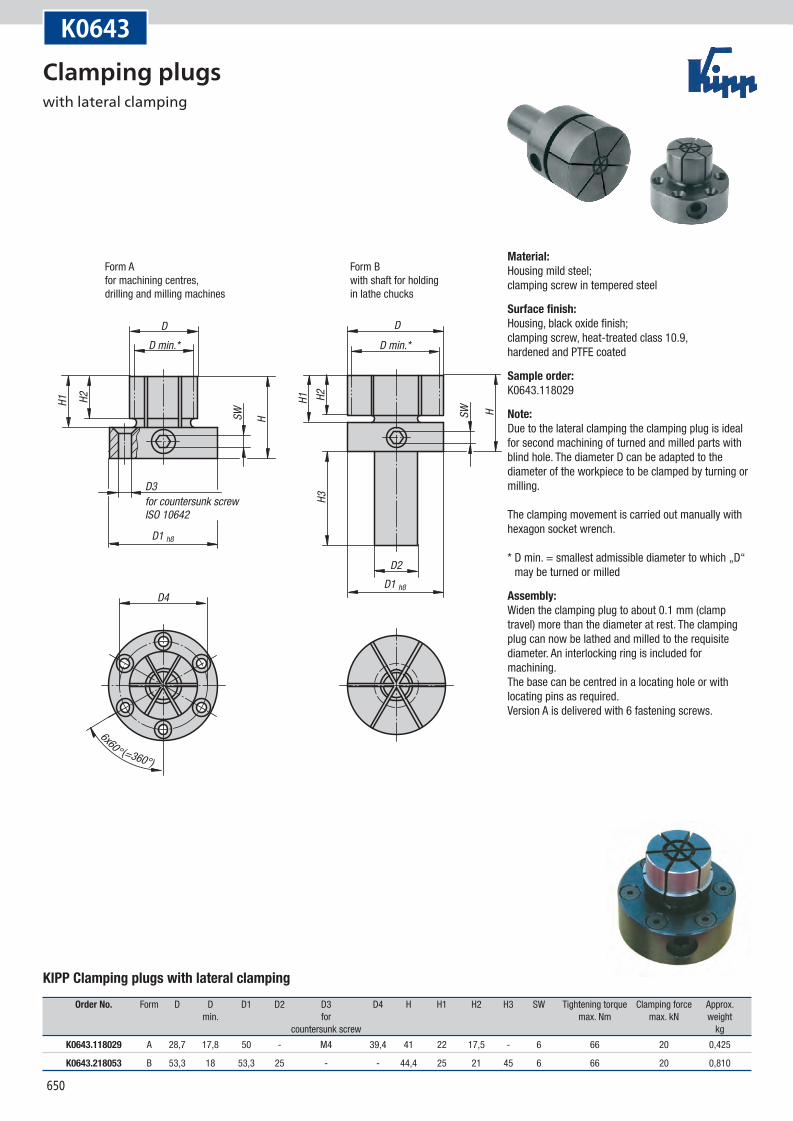
K0643
KIPP Clamping plugs with lateral clamping
Order No. Form D D D1 D2 D3 D4 H H1 H2 H3 SW Tightening torque Clamping force Approx. min. for max. Nm max. kN weight countersunk screw kg
K0643.118029 A 28,7 17,8 50 - M4 39,4 41 22 17,5 - 6 66 20 0,425
K0643.218053 B 53,3 18 53,3 25 - - 44,4 25 21 45 6 66 20 0,810
Material:Housing mild steel; clamping screw in tempered steel
Surface finish:Housing, black oxide finish; clamping screw, heat-treated class 10.9, hardened and PTFE coated
Sample order:K0643.118029
Note:Due to the lateral clamping the clamping plug is ideal for second machining of turned and milled parts with blind hole. The diameter D can be adapted to the diameter of the workpiece to be clamped by turning or milling. The clamping movement is carried out manually with hexagon socket wrench. * D min. = smallest admissible diameter to which „D“
may be turned or milled
Assembly:Widen the clamping plug to about 0.1 mm (clamp travel) more than the diameter at rest. The clamping plug can now be lathed and milled to the requisite diameter. An interlocking ring is included for machining. The base can be centred in a locating hole or with locating pins as required. Version A is delivered with 6 fastening screws.
Clamping plugs with lateral clamping
651
g6
A ±0,1
A ±0,1
L +0,5
D3 H7
D4 +0,5
ball
hexagonForm Bflat, non-marking
Form Aspherical, point contact
mounting dimensions
D max.
D min.
D min. +1
mounting aid:pin to accurately positionthe mandrel segments
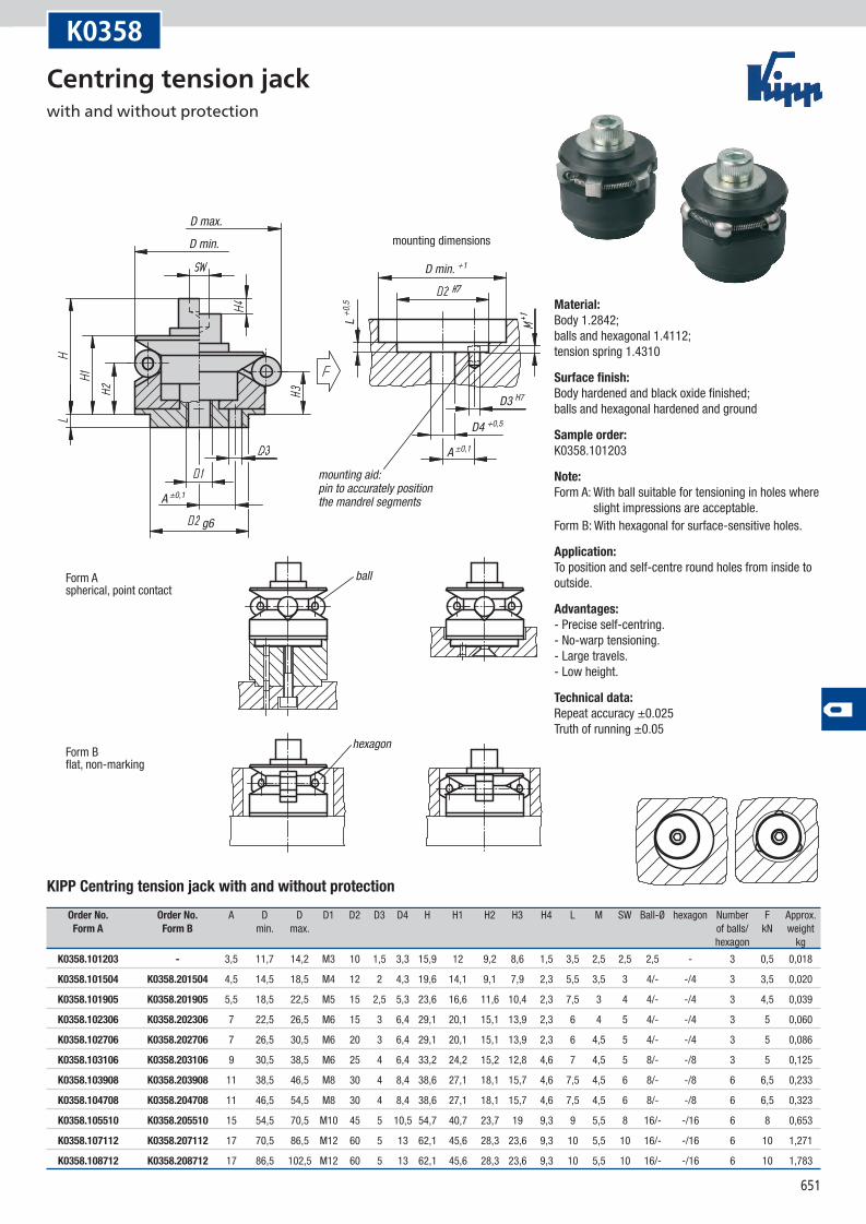
K0358
KIPP Centring tension jack with and without protection
Order No. Order No. A D D D1 D2 D3 D4 H H1 H2 H3 H4 L M SW Ball-Ø hexagon Number F Approx. Form A Form B min. max. of balls/ kN weight hexagon kg
K0358.101203 - 3,5 11,7 14,2 M3 10 1,5 3,3 15,9 12 9,2 8,6 1,5 3,5 2,5 2,5 2,5 - 3 0,5 0,018
K0358.101504 K0358.201504 4,5 14,5 18,5 M4 12 2 4,3 19,6 14,1 9,1 7,9 2,3 5,5 3,5 3 4/- -/4 3 3,5 0,020
K0358.101905 K0358.201905 5,5 18,5 22,5 M5 15 2,5 5,3 23,6 16,6 11,6 10,4 2,3 7,5 3 4 4/- -/4 3 4,5 0,039
K0358.102306 K0358.202306 7 22,5 26,5 M6 15 3 6,4 29,1 20,1 15,1 13,9 2,3 6 4 5 4/- -/4 3 5 0,060
K0358.102706 K0358.202706 7 26,5 30,5 M6 20 3 6,4 29,1 20,1 15,1 13,9 2,3 6 4,5 5 4/- -/4 3 5 0,086
K0358.103106 K0358.203106 9 30,5 38,5 M6 25 4 6,4 33,2 24,2 15,2 12,8 4,6 7 4,5 5 8/- -/8 3 5 0,125
K0358.103908 K0358.203908 11 38,5 46,5 M8 30 4 8,4 38,6 27,1 18,1 15,7 4,6 7,5 4,5 6 8/- -/8 6 6,5 0,233
K0358.104708 K0358.204708 11 46,5 54,5 M8 30 4 8,4 38,6 27,1 18,1 15,7 4,6 7,5 4,5 6 8/- -/8 6 6,5 0,323
K0358.105510 K0358.205510 15 54,5 70,5 M10 45 5 10,5 54,7 40,7 23,7 19 9,3 9 5,5 8 16/- -/16 6 8 0,653
K0358.107112 K0358.207112 17 70,5 86,5 M12 60 5 13 62,1 45,6 28,3 23,6 9,3 10 5,5 10 16/- -/16 6 10 1,271
K0358.108712 K0358.208712 17 86,5 102,5 M12 60 5 13 62,1 45,6 28,3 23,6 9,3 10 5,5 10 16/- -/16 6 10 1,783
Material:Body 1.2842; balls and hexagonal 1.4112; tension spring 1.4310
Surface finish:Body hardened and black oxide finished; balls and hexagonal hardened and ground
Sample order:K0358.101203
Note:Form A: With ball suitable for tensioning in holes where
slight impressions are acceptable.Form B: With hexagonal for surface-sensitive holes.
Application:To position and self-centre round holes from inside to outside.
Advantages:- Precise self-centring. - No-warp tensioning. - Large travels. - Low height.
Technical data:Repeat accuracy ±0.025 Truth of running ±0.05
Centring tension jack with and without protection
652
A ±0,1L +1
M
D2 H7
D3
L1 +1
H2H1
HL2
L
H4H3
F
D2 f7
D1
A
mounting dimensions
D min. +1
mounting aid:pin to accurately positionthe mandrel segments
counterboreDIN 974-1
Form Aspherical, point contact
Csocket head screwISO 4762
ball
hexagonForm Bflat, non-marking
D max.D min.
L1 m
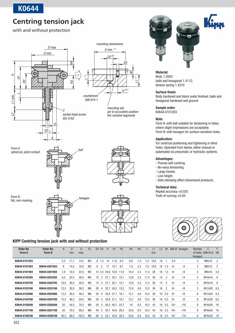
in.K0644
KIPP Centring tension jack with and without protection
Order No. Order No. A D D D1 D2 D3 H H1 H2 H3 H4 L L1 L2 M Ball-Ø hexagon Number C F Form A Form B min. max. min. of balls/ (DIN 912) kN hexagon
K0644.0101203 - 5,2 11,7 14,2 M3 8 1,5 15 11,9 9,2 8,6 1,5 7,5 19,5 10 1 2,5 - 3 M6x10 2
K0644.0101503 K0644.0201503 6 14,5 18,5 M3 8 2 17 14,1 9,1 7,9 2,3 7,5 19,5 10 1,5 4/- -/4 3 M6x10 2
K0644.0101904 K0644.0201904 7,8 18,5 22,5 M4 12 2,5 20,6 16,6 11,6 10,4 2,3 11,5 28 16 1,5 4/- -/4 3 M8x16 3,5
K0644.0102305 K0644.0202305 9,4 22,5 26,5 M5 15 3 27,1 20,1 15,1 13,9 2,3 11,5 30 14 2 4/- -/4 3 M10x16 6
K0644.0102705 K0644.0202705 10,5 26,5 30,5 M5 15 3 27,1 20,1 15,1 13,9 2,3 11,5 30 14 2 4/- -/4 3 M10x16 6
K0644.0103106 K0644.0203106 12,5 30,5 38,5 M6 20 4 32,7 24,2 15,2 12,8 4,6 15,5 36 16 2 8/- -/8 3 M12x20 8,5
K0644.0103906 K0644.0203906 12,5 38,5 46,5 M6 20 4 35,6 27,1 18,1 15,7 4,6 15,5 36 16 2,5 8/- -/8 6 M12x20 8,5
K0644.0104706 K0644.0204706 12,5 46,5 54,5 M6 20 4 35,6 27,1 18,1 15,7 4,6 15,5 36 16 2,5 8/- -/8 6 M12x20 8,5
K0644.0105508 K0644.0205508 20 54,5 70,5 M8 30 5 50,2 40,7 23,7 19 9,3 16,5 43 16 2,5 16/- -/16 6 M16x20 16
K0644.0107108 K0644.0207108 25 70,5 86,5 M8 40 5 55,1 45,6 28,3 23,6 9,3 16,5 43 16 2,5 16/- -/16 6 M16x20 16
K0644.0108708 K0644.0208708 36,5 86,5 102,5 M8 60 5 55,1 45,6 28,3 23,6 9,3 16,5 43 16 2,5 16/- -/16 6 M16x20 16
Material:Body 1.2842; balls and hexagonal 1.4112; tension spring 1.4310
Surface finish:Body hardened and black oxide finished; balls and hexagonal hardened and ground
Sample order:K0644.0101203
Note:Form A: with ball suitable for tensioning in holes, where slight impressions are acceptable. Form B: with hexagon for surface-sensitive holes.
Application:For centrical positioning and tightening in blind holes. Operated from below, either manual or automated via pneumatic or hydraulic systems.
Advantages:- Precise self-centring. - No-warp tensioning. - Large travels. - Low height. - Side clamping effect (downward pressure).
Technical data:Repeat accuracy ±0.025 Truth of running ±0.05
Centring tension jack with and without protection
653
D2 h1
1
D3 GD
G1 SWL1 L1
H
X +0,
2
D1 +0
,2
SW
G1
female thread formounting and removal
L max.
Application:
axial and radial clampingadjusting and clamping
Shafts situated away from the outer edgecan also be clamped using spacer ringsand longer screws (without mounting thread).
spacer rings Kfor deep holes
assembly tool
Special hex key with a threaded pin. The pin is screwed into the hole G1 in the head of the cap screw to aid in positioning or removing the clamping unit.
clamping torque Mx
Mounting instructions:
Insert clamping unit
Insert shaft or tube
Clamp shaft or tube
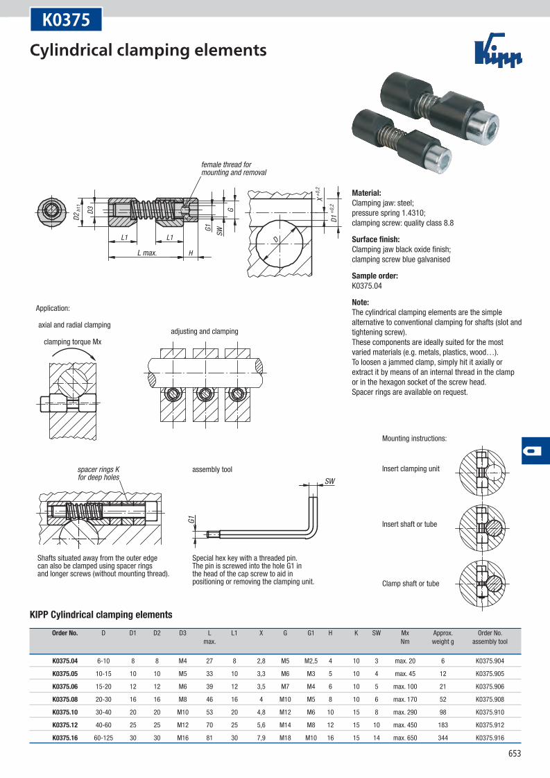
K0375
KIPP Cylindrical clamping elements
Order No. D D1 D2 D3 L L1 X G G1 H K SW Mx Approx. Order No. max. Nm weight g assembly tool
K0375.04 6-10 8 8 M4 27 8 2,8 M5 M2,5 4 10 3 max. 20 6 K0375.904
K0375.05 10-15 10 10 M5 33 10 3,3 M6 M3 5 10 4 max. 45 12 K0375.905
K0375.06 15-20 12 12 M6 39 12 3,5 M7 M4 6 10 5 max. 100 21 K0375.906
K0375.08 20-30 16 16 M8 46 16 4 M10 M5 8 10 6 max. 170 52 K0375.908
K0375.10 30-40 20 20 M10 53 20 4,8 M12 M6 10 15 8 max. 290 98 K0375.910
K0375.12 40-60 25 25 M12 70 25 5,6 M14 M8 12 15 10 max. 450 183 K0375.912
K0375.16 60-125 30 30 M16 81 30 7,9 M18 M10 16 15 14 max. 650 344 K0375.916
Material:Clamping jaw: steel; pressure spring 1.4310; clamping screw: quality class 8.8
Surface finish:Clamping jaw black oxide finish; clamping screw blue galvanised
Sample order:K0375.04
Note:The cylindrical clamping elements are the simple alternative to conventional clamping for shafts (slot and tightening screw). These components are ideally suited for the most varied materials (e.g. metals, plastics, wood…). To loosen a jammed clamp, simply hit it axially or extract it by means of an internal thread in the clamp or in the hexagon socket of the screw head. Spacer rings are available on request.
Cylindrical clamping elements

654

1031
The standard terms and conditions of sale, delivery and payment that you can find on our website www.kipp.com apply.
Heinrich Kipp Werk KG
Postfach 11 60DE-72168 Sulz a.N.
Tel.: +49 (0) 7454 793-0Fax: +49 (0) 7454 793-33Internet www.kipp.comE-Mail [email protected] [email protected]


![clamping devices - HAINBUCH · HAINBUCH clamping devices Flexibility is trump system The HAINBUCH modular system Clamping head change-over [15 sec.] Change-over to mandrel adaptation](https://static.fdocuments.us/doc/165x107/5e6c811c17cf9c2bef5b9293/clamping-devices-hainbuch-clamping-devices-flexibility-is-trump-system-the-hainbuch.jpg)