
CL1PSU-2A CC-Link/LT Dedicated Power Supply User's...
3
Side A Side B JAPANESE Side B ENGLISH ●SAFETY PRECAUTIONS● (Read these precautions before using) Please read this manual carefully and pay special attention to safety in order to handle this product properly. These precautions apply only to Mitsubishi equipment. Refer to the user’s manual of the CPU module for a description of the PLC system safety precautions. If the equipment is used in a manner not specified by the manufacturer, the protection provided by the equipment may be impaired. These ●SAFETY PRECAUTIONS● are classified into two categories: "WARNING" and "CAUTION". Depending on circumstances, procedures indicated by may also be linked to serious results. In any case, it is important to follow the directions for usage. Store this manual in a safe place so that it may be accessible whenever necessary. Always forward this manual to the end user of the machine containing this product. [DESIGN PRECAUTIONS] [INSTALLATION PRECAUTIONS] [WIRING PRECAUTIONS] Procedures which may lead to a dangerous condition and cause death or serious injury if not carried out properly. Procedures which may lead to a dangerous condition and cause superficial to medium injury, or physical damage only, if not carried out properly. • Depending on a failure in the remote I/O module, an output's status may be ON or OFF. For output signals which can lead to a severe accident, install a circuit to monitor the outputs outside of the module. • Do not bind the control cable or the connection cable together with the main circuit and power cable. Keep such cables far from the main circuit and power cable. Assure a distance of 100mm (3.94") or more, otherwise a malfunction may occur due to excessive noise. • Use the dedicated power supply without applying any force on the connector of the CC-Link/LT interface and the connection cable. Otherwise, such cables may break or fail. • Use the dedicated power supply within an environment described by the general specifications in this manual. If the dedicated power supply is used in any environment outside the range for the general specifications, electrical shock, fire, malfunction, product damage or product deterioration may occur. • Do not directly touch the conductive area of the dedicated power supply. Malfunction or damage of the dedicated power supply may be caused by such touching. • Securely fix the dedicated power supply with DIN rail or mounting screws. Securely tighten the mounting screws within the specified torque range. If the screws are insufficiently tightened, the dedicated power supply may drop, short-circuit or malfunction. If the screws are excessively tightened, the screws may be damaged, and the dedicated power supply may drop or short-circuit. • Install the dedicated power supply on to a flat surface. If the mounting surface is concave and/or convex, and if excessive force is applied on the PC board, nonconformity may occur. • Make sure to shut down all phases of the power supply outside the module before starting the installation or wiring work. If all phases are not shut down, electrical shock or product damage may be caused. • The temperature rating of the cable should be 80°C or more. [STARTING AND MAINTENANCE PRECAUTIONS] [DISPOSAL PRECAUTIONS] [TRANSPORTATION AND MAINTENANCE PRECAUTIONS] ●Note Concerning the CE Marking● This marking does not guarantee that an entire mechanical module produced in accordance with the contents of the notification comply with the following standards. Compliance to EMC standards of the entire mechanical module should be checked by the user / manufacturer. Attention This product is designed for use in industrial applications. Standards with which this product complies Type : Programmable Controller (Open Type Equipment) Electromagnetic Compatibility Standards (EMC): Models : Products manufactured: from April 1st, 2004 to April 30th, 2006 are compliant with EN61000-6-4 and EN61131-2:1994+A11:1996+A12:2000 after May 1st, 2006 are compliant with EN61131-2:2007. Low Voltage Standards (LVD): Models : Products manufactured: from November 1st, 2002 to April 30th, 2006 are compliant with EN61000-6-4 and EN61131-2:1994+A11:1996+A12:2000 from May 1st, 2006 to February 28th, 2018 are compliant with EN61131-2:2007 after March 1st, 2018 are compliant with EN61010-2-201:2013 *1 . *1 For products manufactured after January 1 2018, there may be compliant cases. • Confirm the rated voltage and the terminal arrangement of the dedicated power supply, then correctly wire the dedicated power supply. If a power supply not conforming to the specification rating is connected or the dedicated power supply is wired incorrectly, fire, failure or malfunction may occur. • Tighten the terminal screws within the specified torque range. If the terminal screws are insufficiently tightened, fire or malfunction may occur. If the terminal screws are excessively tightened, the screws may be damaged, and the module may short-circuit, equipment failures, or malfunction. • Make sure that foreign objects such as cutting and wire chips do not enter the dedicated power supply. Fire, failure or malfunction may be caused by the foreign objects. • When two or more dedicated power supply or power adapter (CL1PAD1) exist in a system, take care in connecting the first LINK/POWER connector to the second LINK connector as indicated below. If the LINK/POWER connector in the two adapters are connected to each other, the adapters may fail. • Do not short-circuit the 24G terminal and +24V terminal of the LINK/POWER connector. Some remote I/O modules operate the inputs and outputs using the power supply for communication. Refer to the corresponding manuals for remote I/O modules and perform wiring correctly. If wiring is performed incorrectly, fire, failure or malfunction may occur. • When the LINK connector is not in use, cover the opening by plugging a connector for communication (without any cable) or attaching a piece of tape to prevent dust or conductive foreign materials from getting inside. Such materials may cause failure or malfunction. • Attach a warning label (hazard symbol 417-IEC-5036) concerning electric shock to the enclosure of the final system. • Do not touch the terminals while the power is being supplied. Electrical shock or malfunction may be caused by such touching. • Shut down all phases of the power supply outside the dedicated power supply before cleaning or tightening the terminal screws. If all phases are not shut down, the dedicated power supply may fail or malfunction. • For cleaning, perform dry wiping without using chemicals. • If there is the possibility of touching the PLC inside a control panel in maintenance, make sure to discharge to avoid the influence of static electricity. • Do not disassemble or modify the dedicated power supply. Failure, malfunction, injury or fire may be caused by such disassembly or modification. • The dedicated power supply case is made of a resin. The dedicated power supply may be damaged by dropping or strong impact. • Shut down all external phases of the power supply before attaching or removing the dedicated power supply to/from the panel. If all phases are not shut down, the dedicated power supply may fail or malfunction. Correct connection LINK connector LINK connector LINK/ POWER connector Wrong connection LINK connector LINK/ POWER connector LINK connector LINK/ POWER connector LINK/ POWER connector • When disposing of the product, treat it as an industrial waste. • During transportation avoid the impact which exceeds a regulated value as the dedicated power supply is a precision instrument. It is necessary to check the operation of module after transportation, in case of any impact damage. If not checked, an accident or damage to the machine may result due to a damaged dedicated power supply. . For more details please contact the local Mitsubishi Electric sales site. • Notes for compliance to EMC LVD regulation. It is necessary to install the CL1 series module in a shielded metal control panel. • Use this product in Zone A *2 as defined in EN61131-2. The terminal and the wiring for the power supply can be used in zone B *2 . *2 Zone defined in EN61131-2 Separation defined in EN61131-2 for EMC LVD regulation decided depending on condition in industrial setting. Zone C = Factory mains which is isolated from public mains by dedicated transformers. Zone B = Dedicated power distribution which is protected by secondary surge protection. (300V or less in the rated voltage is assumed.) Zone A = Local power distribution which is isolated from dedicated power distribution by AC/DC converters, isolation transformers, etc. (120V or less in the rated voltage is assumed.) • Do not wire two or more crimp terminals to one terminal. (If the wiring with two or more wire is needed, take an appropriate action such as adding an external terminal.) Installation in Enclosure Please use the CL1 Series module while installed in conductive shielded control panels under a general industrial environment. Programmable controllers are open-type devices that must be installed and used within conductive control panels. Please secure the control panel lid to the control panel (for conduction). Installation within a control panel greatly affects the safety of the system and aids in shielding noise from the programmable controller. • For the control panel, use the product having sufficient strength, fire protectiveness and shielding property to an installation environment. 1. Associated manuals 2. Outline of Product This product is a dedicated power supply connected to CC-Link/LT. This product supplies 24V DC power to the CC-Link/LT system. Electromagnetic Compatibility Standards (EMC) Remark EN61000-6-4:2001 Electromagnetic compatibility -Generic standards - Emission standard for Industrial environment Compliance with all relevant aspects of the standard. (Radiated Emissions and Mains Terminal Voltage Emissions) EN61131-2:1994/A11:1996/A12:2000 Programmable controllers -Equipment requirements and tests Compliance with all relevant aspects of the standard. • Radiated electromagnetic field • Fast transient burst • Electrostatic discharge • Damped oscillatory wave EN61131-2: 2007 Programmable controllers -Equipment requirements and tests Compliance with all relevant aspects of the standard. EMI • Radiated Emission • Conducted Emission EMS • Radiated electromagnetic field • Fast transient burst • Electrostatic discharge • High-energy surge • Voltage drops and interruptions • Conducted RF • Power frequency magnetic field Low Voltage Standards (LVD) Remark EN61131-2:1994/A11:1996 /A12:2000 :2007 Programmable controllers -Equipment requirements and tests The equipment has been assessed as a component for fitting in a suitable control box which meets the requirements of EN61131-2:1994 + A11:1996 + A12:2000, :2007 EN61010-2-201:2013 Safety of electrical equipment for measurement, control, and test The equipment has been assessed as a component for fitting in a suitable control box which meets the requirements of EN61010-2-201:2013 Manual name Manual No. (Model code) Description CC-Link/LT: Power Adapter • Dedicated Power Supply USER’S MANUAL (Detailed Volume) JY997D06601 (09R712) Explains specifications, wiring, handling regarding the dedicated power supply and dedicated power supply for CC-Link/LT 3. Name of Each Part 3.1 Name of each part and assignment 3.2 Handling of LINK connector and LINK/POWER connector 1) LINK connector Dedicated for communication only (does not supply power). Used when two or more dedicated power supply or power adapter (CL1PAD1) are used in the CC-Link/LT system. 2) LINK/POWER connector Dedicated for communication, and supplies the power to the CC-Link/LT system. 4. Specifications 1) General specifications CL1PSU-2A AC85 -264V 24V LINK - - DB DA - - LINK/ POWER 24G DB DA +24V L N DIN rail installation groove Nameplate LINK connector LINK/POWER connector Status indicator LED Power terminal 2- φ 4.5 mounting hole (M4 mounting screw) Terminal arrangement L N Name Description Status indicator LED 24V Lit while the power is supplied Interface LINK connector DB For communication DA For communication Interface LINK/ POWER connector 24G Power supply for communication (-) DB For communication DA For communication +24V Power supply for communication (+) Power terminal L Supplies power from outside to dedicated power supply. Input voltage: 100,120,200,230,and 240V AC (Voltage allowable range: 85 to 264V AC) N shows a function grounding terminal. Nameplate printing is a mark that instructs to use the cable with an appropriate temperature rating (80°C or more) for wiring Item Specification Ambient working temperature 0 to 55°C (32 to 131°F) Ambient storage temperature -25 to 75°C (-13 to 167°F) Ambient operating humidity 5 to 95%RH: Dew condensation shall not be allowed. Ambient storage humidity 5 to 95%RH: Dew condensation shall not be allowed. Vibration resistance (*1) Intermittent vibration is present Number of sweep times Frequency Acceleration Half amplitude 10 times in each of X, Y and Z directions (80 min) 10 to 57Hz − 0.075mm 57 to 150Hz 9.8m/s 2 − Continuous vibration is present Frequency Acceleration Half amplitude 10 to 57Hz − 0.035mm 57 to 150Hz 4.9m/s 2 − Impact resistance (*1) 147 m/s 2 , 3 times in each of X, Y and Z directions Operating atmosphere Corrosive gas should not be present. Master module Dedicated Power Supply 1) 2) 1) 2) Dedicated Power Supply Remote I/O station Remote I/O station Remote I/O station Remote I/O station Thank you very much for choosing this product. CL1PSU-2A CC-Link/LT Dedicated Power Supply Please read this manual thoroughly before starting to use or handling the product. User’s Manual MODEL CL1PSU-2A MANUAL Number JY997D09801G Date December 2017
Transcript of CL1PSU-2A CC-Link/LT Dedicated Power Supply User's...
*1 The criterion is shown in IEC61131-2.*2 The module cannot be used in an environment pressurized above the
atmospheric pressure at the altitude of 0 m. If the module is used in suchan environment, it may fail.
*3 This category indicates in which area (inside the site) in relation to thepublic wiring net the equipment is to be connected.Category ΙΙ applies, for example, to equipment whose power is suppliedfrom a fixed facility.The surge-resistant voltage of equipment whose rating is up to 300V is 2,500V.
*4 This index indicates the degree of conductive substances generated in theenvironment in which the module is used. The degree of contamination 2indicates that contamination is caused by the generation of only non-conductive substances.In this degree, however, temporary conduction may be caused byaccidental condensation.
*5 CC-Link/LT system is assumed to be installed in an environmentequivalent to indoor.
2) Performance specifications
Output derating
• The output current that can be used varies depending on the ambient temperature, therefore, refer to the output derating chart above and use the module within its proper range. (When load factor is at 100%, up to 2A current can be output. At 80%, up to 1.6A.)
• When the output current exceeds the specified value, an overcurrent protection circuit drives the output voltage down.When the overcurrent status or short circuit is cleared, the output voltage automatically returns to its normally operating value.
• When an output voltage exceeding the specified value is generated due to some defect inside the power supply, for instance, the output is interrupted so that the high voltage will not be output.The protection circuit may also be triggered when a reverse current is generated from the load circuit connected to the output terminal or when an external overvoltage is input.If the overvoltage protection circuit is triggered once, and the output is interrupted and does not return to normal automatically, please have the module checked and/or repaired.
Operating altitude 2,000m(6561'8") or less (*2)Installation place Inside control panel (*5)Over-voltage category ΙΙ or less (*3)Degree of contamination 2 or less (*4)Grounding 100Ω or less
Item Specification
Item Specification
Input
Rated voltage 100, 120, 200, 230, and 240V ACVoltage allowable range 85 to 264V AC
Rated current 1.2A / 100V AC 0.7A / 200V ACPower consumption 70W
Rated frequency 50 or 60Hz
Power fuse 3.15AInrush current Max. 50A / 100V AC Max. 60A / 200V AC
Output
Output voltage 24V DC +10 %/-5 %
Output current
0.01A to 2A Derating occurs according to the ambient temperature and power voltage.[Use the module in a proper range so that the total current consumption of each module does not exceed 2A (except the period immediately after the power is turned on).]
Ripple noise 500mVp-p or below
Noise resistance By noise simulator of 1000Vp-p in noise voltage, 1µs in noise width, and 25 to 60Hz in frequency
Withstand voltage AC type 1500V AC for one min.DC type 500V AC for one min.
Allowable momentary power failure time
Operation continues after power failure for 10ms or less.
Insulation resistance10 MΩ between the external terminals as a whole and the ground terminal by 500V DC insulation resistance tester
Protection class IP1X
Protec-tion func-tion
Over-voltage protection
27V to 33V Output interrupt Not automatically reset
Overcurrent protection
110 to 160%Drooping characteristic Automatically reset
External connection method
-Supplies power from outside to dedicated power supply: 3 points (M3 screws) on terminal block
-To communicate and to supply power to CC-Link/LT system: Connector with 4 pins dedicated to CC-Link/LT (2 pcs.)
Mass (Weight) Approx. 0.4 kg (0.88 lbs)
Ambient temperature (°C)
Load
fact
or (%
)
0
20
40
60
80
100
0 10 20 30 40 50 55
100V AC or higher90V AC85V AC
5. Construction CautionsInstallation of dedicated power supplyAt least one dedicated power supply is required per CC-Link/LT system.When constructing the system using only one dedicated power supply, thefollowing three conditions should be satisfied.If the following four conditions are not satisfied, use two or more dedicated powersupplies or power adapters (CL1PAD1) in constructing the system.• The current capacity of the dedicated power supply is 2A or less, therefore, total
current consumption should be an equivalent to or less than 2 A.• Total current at start-up of each module + current consumption of the I/O
equipment that receives power from a dedicated power supply ≤ Maximum output current (2.2A) of dedicated power supply
• In order to operate a stable system, the voltage drop should be equivalent to or less than 3.6 V.
• The minimum operating voltage of each module is 20.4 V, therefore, supply voltage subtracted by the voltage drop should be equivalent to or more than 20.4 V.
5.1 System power calculation method5.1.1 Current consumption calculation
*1 Some remote I/O modules for CC-Link/LT supply the power for I/O via theconnection cable.For the details, refer to the instruction manual of each remote I/O module.
5.1.2 Voltage dropCalculate the voltage drop based on the simplified graph or the calculationformula. (supply voltage: 24V DC, ambient temperature: 20°C)1) Selection based on the simplified graph
One dedicated power supply is allowed within the range shown in the graph above.2) Selection based on the calculation formula
*1 Some remote I/O modules for CC-Link/LT supply the power for I/O via theconnection cable.For the details, refer to the instruction manual of each remote I/O module. The simplified graph and the calculation formula concerning voltage dropcalculations may not be accurate depending on the ambient temperatureand the number of used connectors dedicated to CC-Link/LT.If the driving voltage (20.4V) cannot be assured in a used remote I/Omodule, add another dedicated power supply or power adapter (CL1PAD1).
5.1.3 Start-up current calculationConstruct the system properly so that the calculated start-up current (when thepower is turned on) does not exceed the maximum output current (2.2 A) of thededicated power supply.
• Refer to "CC-Link/LT: Power Adapter • Dedicated Power Supply USER'S MANUAL (Detailed Volume)"
Currentconsumptionin CC-Link/LT
system
Total currentconsumption ofeach module in
CC-Link/LT system
Total current consumptionof I/O equipment (suchas sensors) (to whichpower is supplied via
communication cable)*1= + ≤ 2A
0.10.1
1.0
10
100
560
1.0 5Current consumption [A]
1000
0.10.1
1.0
10
100
441
1.0 5Current consumption [A]
1000
When you use VCTF cable or High flexiblecable or a combination of cables When you use dedicated flat cable
Max
imum
cab
le le
ngth
[m(in
ches
)]
Max
imum
cab
le le
ngth
[m(in
ches
)]
Voltagedrop (V)
Maximumdistance (m)
+ Constant: 9Constant
: 0.08= × ≤ 3.6V× Total currentconsumption (A)
Maximumdistance
Total currentconsumption
Furthest station from the dedicated power supply
Total currentconsumption of eachmodule in CC-Link/LT
system+
Total current consumption of I/Oequipment (such as sensors)
(to which power is supplied viacommunication cable)*1
Voltagedrop (V)
Maximumdistance (m)
+ Constant: 11Constant
: 0.06= × ≤ 3.6V× Total currentconsumption (A)
When you use VCTF cable or High flexible cable or a combination of cables
When you use dedicated flat cable
Total current atstart-up of each
module ofCC-Link/LT
≤+Total current consumption of I/O
equipment (such as sensors)(to which power is supplied via a
connecting cable)
Maximum outputcurrent (2.2 A) ofdedicated power
supply
6. InstallationThe dedicated power supply can be installed to a DIN rail or directly installed with screws.Provide a space of 50mm (1.97 in.) or more between the dedicated power supplymain unit and other equipment or structures. Keep the module as far away fromhigh-voltage cables, high-voltage devices, or power-driven devices as possible. Each installation procedure is described below.6.1 Installation directionDo not install the dedicated power supply on the floor surface, the ceilingsurface or in the vertical direction. If the dedicated power supply is installed onsuch a surface or in such a direction, its temperature may rise.Make sure to install the dedicated power supply on the wall horizontally.6.2 Installation to DIN railWhen installing the module, 1) align the upper DIN rail installation groove on themodule with the DIN rail, and 2) press the module on to the DIN rail.When removing the module, 3) pull the hook downward for installation to DIN rail,4) then remove the module.
6.3 Direct installationMount the dedicated power supply by tightening M4 screws to the upper andlower mounting holes (two holes in all) provided in the dedicated power supply.
7. Power Wiring
Crimp-style terminalFor the power wiring, use crimp-style terminals of the following dimensions.For the I/O wiring, use crimp-style terminals of the following dimensions.
• Use a power wire of 2mm2 (0.08in.2) or more.• Perform grounding (100Ω or less) with a wire of 2 mm2 (0.08in.2) or more to
the grounding terminal. However, never perform common grounding with a high voltage system.
• Tighten the terminal screws (M3 screws) on the terminal block with a tightening torque of 0.42 to 0.58 N•m. Do not tighten terminal screws exceeding the specified torque. Failure to do so may cause short circuit, equipment failures, or malfunctions.
*1 To adapt the low voltage command (EN61010-2-201:2013) of the EC commandavoid the wiring with two wires to the built-in terminal, and take an appropriateaction such as adding an external terminal.
8. Outside Dimensions
Applicable DIN rail TH35-7.5Fe and TH35-7.5AIWidth: 35mm (1.38")
Applicable screw M4 × 0.7mm(0.03") × 16mm(0.63") or more(Tightening torque range: 0.78 to 1.08 N⋅m)
1)
Installation Removal
2) 3)
4)
Connector forCC-Link/LTinterface
DADB
Connector forCC-Link/LT interface
Power terminal block for dedicated power supply
Grounding(100Ω or less)
+24VDA
24GDB
LINK LINK/POWER
NL
Dedicated power supply
100, 120, 200, 230, and 240V AC (Voltage allowable range: 85 to 264V AC)
AC/DC circuit
LED24V
6.2 mm (0.24" )or less
6.2 mm (0.24" )or less
Terminal
Terminal screw Crimp-styleterminal
Terminal screw Crimp-styleterminal
When wiring one cable to one terminal When wiring two cables to one terminal*1
Terminal
φ 3.2 (0.13") φ 3.2 (0.13")
CL1PSU-2A
AC85-264V
24V
LINK - -DBDA- -
LINK/POWER
24GDBDA
+24V
L N
Center of DIN rail
2 - φ4.5(0.18") mountinghole (M4 mounting screw)
90(3.55")
45(1
.78"
)
Unit: mm(inches)
8(0.32")82(3.23")±0.3(0.02")
90(3
.55"
)
82(3
.23"
)±0.
3(0.
02")
90(3.55")
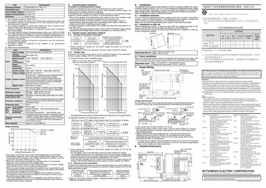
3.2 Handling of LINK connector and LINK/POWER connector
1) LINK connectorDedicated for communication only (does not supply power). Used whentwo or more dedicated power supply or power adapter (CL1PAD1) areused in the CC-Link/LT system.
2) LINK/POWER connectorDedicated for communication, and supplies the power to the CC-Link/LT system.
4. Specifications1) General specifications
Interface connector DA For communication
InterfaceLINK/POWER connector
24G Power supply for communication (-)DB For communicationDA For communication+24V Power supply for communication (+)
Power terminal
L Supplies power from outside to dedicated power supply.Input voltage:100,120,200,230,and 240V AC(Voltage allowable range: 85 to 264V AC)
N
shows a function grounding terminal.
Nameplate printing is a mark that instructs to use the cable with an appropriate temperature rating (80°C or more) for wiring
Item SpecificationAmbient working temperature 0 to 55°C (32 to 131°F)
Ambient storage temperature -25 to 75°C (-13 to 167°F)
Ambient operating humidity
5 to 95%RH: Dew condensation shall not be allowed.
Ambient storage humidity
5 to 95%RH: Dew condensation shall not be allowed.
Vibration resistance (*1)
Intermittent vibration is present Number of sweep times
Frequency Acceleration Half amplitude
10 times in each of X, Y and Z directions (80 min)
10 to 57Hz − 0.075mm57 to 150Hz 9.8m/s2 −Continuous vibration is presentFrequency Acceleration Half amplitude10 to 57Hz − 0.035mm57 to 150Hz 4.9m/s2 −
Impact resistance (*1) 147 m/s2, 3 times in each of X, Y and Z directionsOperating atmosphere Corrosive gas should not be present.
COMM.
1
COMM.
1
Master module
DedicatedPower Supply
1)
2)
1)
2)
DedicatedPower Supply
Remote I/O stationRemote I/O stationRemote I/O stationRemote I/O station
SideA
Side
B
JAPANESE
SideB ENGLISH
SAFETY PRECAUTIONS(Read these precautions before using)
Please read this manual carefully and pay special attention to safety in orderto handle this product properly. These precautions apply only to Mitsubishiequipment. Refer to the user’s manual of the CPU module for a description ofthe PLC system safety precautions.If the equipment is used in a manner not specified by the manufacturer, theprotection provided by the equipment may be impaired.These SAFETY PRECAUTIONS are classified into two categories:"WARNING" and "CAUTION".
Depending on circumstances, procedures indicated by may alsobe linked to serious results.In any case, it is important to follow the directions for usage.Store this manual in a safe place so that it may be accessible whenevernecessary. Always forward this manual to the end user of the machinecontaining this product.[DESIGN PRECAUTIONS]
[INSTALLATION PRECAUTIONS]
[WIRING PRECAUTIONS]
Procedures which may lead to a dangerous condition and cause death or serious injury if not carried out properly.
Procedures which may lead to a dangerous condition and cause superficial to medium injury, or physical damage only, if not carried out properly.
• Depending on a failure in the remote I/O module, an output's status may be ON or OFF. For output signals which can lead to a severe accident, install a circuit to monitor the outputs outside of the module.
• Do not bind the control cable or the connection cable together with the main circuit and power cable. Keep such cables far from the main circuit and power cable. Assure a distance of 100mm (3.94") or more, otherwise a malfunction may occur due to excessive noise.
• Use the dedicated power supply without applying any force on the connector of the CC-Link/LT interface and the connection cable. Otherwise, such cables may break or fail.
• Use the dedicated power supply within an environment described by the general specifications in this manual. If the dedicated power supply is used in any environment outside the range for the general specifications, electrical shock, fire, malfunction, product damage or product deterioration may occur.
• Do not directly touch the conductive area of the dedicated power supply.Malfunction or damage of the dedicated power supply may be caused by such touching.
• Securely fix the dedicated power supply with DIN rail or mounting screws. Securely tighten the mounting screws within the specified torque range. If the screws are insufficiently tightened, the dedicated power supply may drop, short-circuit or malfunction.If the screws are excessively tightened, the screws may be damaged, and the dedicated power supply may drop or short-circuit.
• Install the dedicated power supply on to a flat surface.If the mounting surface is concave and/or convex, and if excessive force is applied on the PC board, nonconformity may occur.
• Make sure to shut down all phases of the power supply outside the module before starting the installation or wiring work. If all phases are not shut down, electrical shock or product damage may be caused.
• The temperature rating of the cable should be 80°C or more.
Thank you very much for choosing this product.
CL1PSU-2ACC-Link/LT Dedicated Power Supply
Please read this manual thoroughly before starting to use or handling the product.
User’s ManualMODEL CL1PSU-2AMANUAL Number JY997D09801GDate December 2017
[STARTING AND MAINTENANCE PRECAUTIONS]
[DISPOSAL PRECAUTIONS]
[TRANSPORTATION AND MAINTENANCE PRECAUTIONS]
Note Concerning the CE MarkingThis marking does not guarantee that an entire mechanical module produced inaccordance with the contents of the notification comply with the followingstandards. Compliance to EMC standards of the entire mechanical moduleshould be checked by the user / manufacturer.
AttentionThis product is designed for use in industrial applications.
Standards with which this product compliesType : Programmable Controller (Open Type Equipment)Electromagnetic Compatibility Standards (EMC):Models : Products manufactured:
from April 1st, 2004 to April 30th, 2006 are compliant withEN61000-6-4 and EN61131-2:1994+A11:1996+A12:2000after May 1st, 2006 are compliant with EN61131-2:2007.
Low Voltage Standards (LVD):Models : Products manufactured:
from November 1st, 2002 to April 30th, 2006 are compliant with EN61000-6-4 and EN61131-2:1994+A11:1996+A12:2000from May 1st, 2006 to February 28th, 2018 are compliant with EN61131-2:2007 after March 1st, 2018 are compliant with EN61010-2-201:2013*1.
*1 For products manufactured after January 1 2018, there may be compliant cases.
• Confirm the rated voltage and the terminal arrangement of the dedicated power supply, then correctly wire the dedicated power supply. If a power supply not conforming to the specification rating is connected or the dedicated power supply is wired incorrectly, fire, failure or malfunction may occur.
• Tighten the terminal screws within the specified torque range. If the terminal screws are insufficiently tightened, fire or malfunction may occur.If the terminal screws are excessively tightened, the screws may be damaged, and the module may short-circuit, equipment failures, or malfunction.
• Make sure that foreign objects such as cutting and wire chips do not enter the dedicated power supply. Fire, failure or malfunction may be caused by the foreign objects.
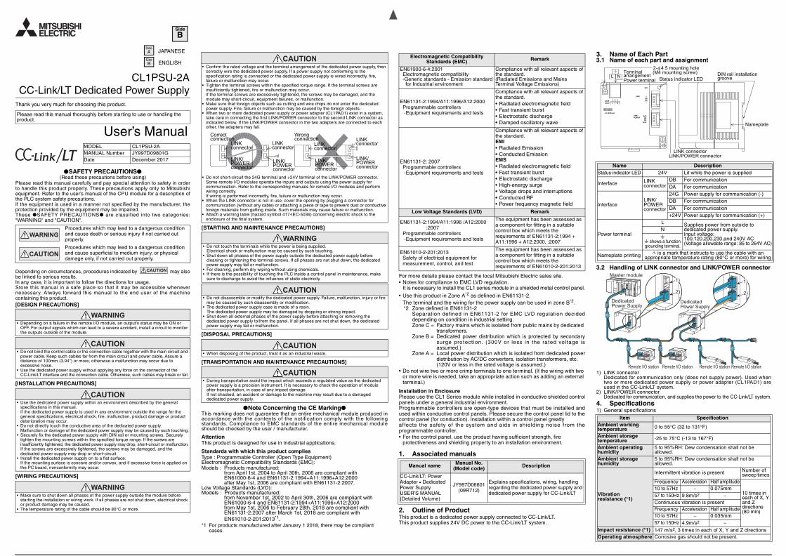
• When two or more dedicated power supply or power adapter (CL1PAD1) exist in a system, take care in connecting the first LINK/POWER connector to the second LINK connector as indicated below. If the LINK/POWER connector in the two adapters are connected to each other, the adapters may fail.
• Do not short-circuit the 24G terminal and +24V terminal of the LINK/POWER connector. Some remote I/O modules operate the inputs and outputs using the power supply for communication. Refer to the corresponding manuals for remote I/O modules and perform wiring correctly.If wiring is performed incorrectly, fire, failure or malfunction may occur.
• When the LINK connector is not in use, cover the opening by plugging a connector for communication (without any cable) or attaching a piece of tape to prevent dust or conductive foreign materials from getting inside. Such materials may cause failure or malfunction.
• Attach a warning label (hazard symbol 417-IEC-5036) concerning electric shock to the enclosure of the final system.
• Do not touch the terminals while the power is being supplied.Electrical shock or malfunction may be caused by such touching.
• Shut down all phases of the power supply outside the dedicated power supply before cleaning or tightening the terminal screws. If all phases are not shut down, the dedicated power supply may fail or malfunction.
• For cleaning, perform dry wiping without using chemicals.• If there is the possibility of touching the PLC inside a control panel in maintenance, make
sure to discharge to avoid the influence of static electricity.
• Do not disassemble or modify the dedicated power supply. Failure, malfunction, injury or fire may be caused by such disassembly or modification.
• The dedicated power supply case is made of a resin.The dedicated power supply may be damaged by dropping or strong impact.
• Shut down all external phases of the power supply before attaching or removing the dedicated power supply to/from the panel. If all phases are not shut down, the dedicated power supply may fail or malfunction.
Correctconnection
LINKconnector
LINKconnector
LINK/POWERconnector
Wrongconnection
LINKconnector
LINK/POWERconnector
LINKconnector
LINK/POWERconnector
LINK/POWERconnector
• When disposing of the product, treat it as an industrial waste.
• During transportation avoid the impact which exceeds a regulated value as the dedicated power supply is a precision instrument. It is necessary to check the operation of module after transportation, in case of any impact damage. If not checked, an accident or damage to the machine may result due to a damaged dedicated power supply.
.
For more details please contact the local Mitsubishi Electric sales site.• Notes for compliance to EMC LVD regulation.
It is necessary to install the CL1 series module in a shielded metal control panel.
• Use this product in Zone A*2 as defined in EN61131-2.The terminal and the wiring for the power supply can be used in zone B*2.*2 Zone defined in EN61131-2
Separation defined in EN61131-2 for EMC LVD regulation decideddepending on condition in industrial setting.Zone C = Factory mains which is isolated from public mains by dedicated
transformers.Zone B = Dedicated power distribution which is protected by secondary
surge protection. (300V or less in the rated voltage isassumed.)
Zone A = Local power distribution which is isolated from dedicated powerdistribution by AC/DC converters, isolation transformers, etc. (120V or less in the rated voltage is assumed.)
• Do not wire two or more crimp terminals to one terminal. (If the wiring with two or more wire is needed, take an appropriate action such as adding an external terminal.)
Installation in EnclosurePlease use the CL1 Series module while installed in conductive shielded controlpanels under a general industrial environment.Programmable controllers are open-type devices that must be installed andused within conductive control panels. Please secure the control panel lid to thecontrol panel (for conduction). Installation within a control panel greatlyaffects the safety of the system and aids in shielding noise from theprogrammable controller.• For the control panel, use the product having sufficient strength, fire
protectiveness and shielding property to an installation environment.
1. Associated manuals
2. Outline of ProductThis product is a dedicated power supply connected to CC-Link/LT.This product supplies 24V DC power to the CC-Link/LT system.
Electromagnetic Compatibility Standards (EMC) Remark
EN61000-6-4:2001Electromagnetic compatibility-Generic standards - Emission standard for Industrial environment
Compliance with all relevant aspects of the standard.(Radiated Emissions and Mains Terminal Voltage Emissions)
EN61131-2:1994/A11:1996/A12:2000Programmable controllers -Equipment requirements and tests
Compliance with all relevant aspects of the standard.• Radiated electromagnetic field• Fast transient burst• Electrostatic discharge• Damped oscillatory wave
EN61131-2: 2007Programmable controllers -Equipment requirements and tests
Compliance with all relevant aspects of the standard.EMI• Radiated Emission• Conducted EmissionEMS• Radiated electromagnetic field• Fast transient burst• Electrostatic discharge• High-energy surge• Voltage drops and interruptions• Conducted RF• Power frequency magnetic field
Low Voltage Standards (LVD) Remark
EN61131-2:1994/A11:1996 /A12:2000:2007
Programmable controllers -Equipment requirements and tests
The equipment has been assessed as a component for fitting in a suitable control box which meets the requirements of EN61131-2:1994 + A11:1996 + A12:2000, :2007
EN61010-2-201:2013Safety of electrical equipment for measurement, control, and test
The equipment has been assessed as a component for fitting in a suitable control box which meets the requirements of EN61010-2-201:2013
Manual name Manual No.(Model code) Description
CC-Link/LT: Power Adapter • Dedicated Power SupplyUSER’S MANUAL(Detailed Volume)
JY997D06601(09R712)
Explains specifications, wiring, handling regarding the dedicated power supply and dedicated power supply for CC-Link/LT
3. Name of Each Part3.1 Name of each part and assignment
CL1PSU-2A
AC85-264V
24V
LINK - -DBDA- -
LINK/POWER
24GDBDA
+24V
L N
DIN rail installationgroove
Nameplate
LINK connectorLINK/POWER connector
Status indicator LEDPower terminal
2-φ4.5 mounting hole(M4 mounting screw)Terminal
arrangementL N
Name DescriptionStatus indicator LED 24V Lit while the power is supplied
LINK DB For communication
Specifications subject to change without notice.
HEAD OFFICE : TOKYO BUILDING, 2-7-3 MARUNOUCHI, CHIYODA-KU, TOKYO 100-8310, JAPAN
When exported from Japan, this manual does not require application to the Ministry of Economy, Trade and Industry for service transaction permission.
This manual confers no industrial property rights or any rights of any other kind, nor does it confer any patent licenses. Mitsubishi Electric Corporation cannot be held responsible for any problems involving industrial property rights which may occur as a result of using the contents noted in this manual.
WarrantyExclusion of loss in opportunity and secondary loss from warranty liabilityRegardless of the gratis warranty term, Mitsubishi shall not be liable for compensation to:(1) Damages caused by any cause found not to be the responsibility of Mitsubishi.(2) Loss in opportunity, lost profits incurred to the user by Failures of Mitsubishi products.(3) Special damages and secondary damages whether foreseeable or not, compensation for accidents, and compensation for damages to products other than Mitsubishi products.(4) Replacement by the user, maintenance of on-site equipment, start-up test run and other tasks.
• This product has been manufactured as a general-purpose part for generalindustries, and has not been designed or manufactured to be incorporated in a device or system used in purposes related to human life.
• Before using the product for special purposes such as nuclear power, electric power, aerospace, medicine or passenger movement vehicles, consult with Mitsubishi Electric.
• This product has been manufactured under strict quality control. Howeverwhen installing the product where major accidents or losses could occur if theproduct fails, install appropriate backup or failsafe functions in the system.
For safe use
Country/Region Sales office/TelUSA MITSUBISHI ELECTRIC AUTOMATION, INC.
500 Corporate Woods Parkway, Vernon Hills, IL 60061, U.S.A.Tel : +1-847-478-2100/+1-847-478-2500 (NC)
Brazil MITSUBISHI ELECTRIC DO BRASIL COMERCIO E SERVICOS LTDA. Avenida Adelino Cardana, 293, 21 andar, Bethaville, Barueri SP, Brazil Tel : +55-11-4689-3000
Germany MITSUBISHI ELECTRIC EUROPE B.V. – German BranchMitsubishi-Electric-Platz 1, 40882 Ratingen, GermanyTel : +49-2102-486-0
UK MITSUBISHI ELECTRIC EUROPE B.V. UK BranchTravellers Lane, Hatfield, Hertfordshire, AL10 8XB, UKTel : +44-1707-28-8780
Italy MITSUBISHI ELECTRIC EUROPE B.V. – Italian BranchCentro Direzionale Colleoni - Palazzo Sirio, Viale Colleoni 7, 20864 Agrate Brianza (MB), ItalyTel : +39-039-60531/+39-039-6053-342
Spain MITSUBISHI ELECTRIC EUROPE, B.V. – Spanish BranchCarretera de Rubi 76-80-AC.420, E-08190 Sant Cugat del Valles (Barcelona), Spain Tel : +34-935-65-3131/+34-935-65-2236
France MITSUBISHI ELECTRIC EUROPE B.V. – French Branch25, Boulevard des Bouvets, 92741 Nanterre Cedex, FranceTel : +33-1-55-68-55-68
Czech Republic MITSUBISHI ELECTRIC EUROPE B.V. Czech BranchAvenir Business Park, Radicka 751/113e, 158 00 Praha5, Czech RepublicTel : +420-251-551-470
Poland Mitsubishi Electric Europe B.V. Polish Branchul. Krakowska 50, 32-083 Balice, PolandTel : +48-12-347-65-00
Country/Region Sales office/TelRussia
China MITSUBISHI ELECTRIC AUTOMATION (CHINA) LTD.Mitsubishi Electric Automation Center, No.1386 Hongqiao Road, Shanghai, ChinaTel : +86-21-2322-3030
Taiwan SETSUYO ENTERPRISE CO., LTD.6F, No.105, Wugong 3rd Road, Wugu District, New Taipei City 24889, Taiwan, R.O.C.Tel : +886-2-2299-2499
Korea MITSUBISHI ELECTRIC AUTOMATION KOREA CO., LTD.7F~9F, Gangseo Hangang Xi-tower A, 401, Yangcheon-ro, Gangseo-Gu, Seoul, 07528, KoreaTel : +82-2-3660-9530
Singapore MITSUBISHI ELECTRIC ASIA PTE. LTD, 307 Alexandra Road, Mitsubishi Electric Building, Singapore 159943 Tel : +65-6473-2308
Thailand Mitsubishi Electric Factory Automation (Thailand) Co., Ltd.12th Floor, SV.City Building, Office Tower 1, No. 896/19 and 20 Rama 3 Road, Kwaeng Bangpongpang, Khet Yannawa, Bangkok 10120, ThailandTel : +66-2682-6522~31
Indonesia PT. Mitsubishi Electric IndonesiaGedung Jaya 11th Floor, JL. MH. ThamrinNo.12, Jakarta Pusat 10340, IndonesiaTel : +62-21-3192-6461
India Mitsubishi Electric India Pvt. Ltd. Gurgaon Head Office2nd Floor, Tower A & B, Cyber Greens, DLF Cyber City, DLF Phase - III, Gurgaon - 122002, Haryana, IndiaTel : +91-124-4630300
Australia MITSUBISHI ELECTRIC AUSTRALIA PTY. LTD.348 Victoria Road PO BOX11, Rydalmere, N.S.W 2116, Australia Tel : + 61-2-9684-7777
Mitsubishi Electric (Russia) LLC52, bld. 1, Kosmodamianskaya emb., 115054 Moscow, RussiaTel : +7-495-721-2070
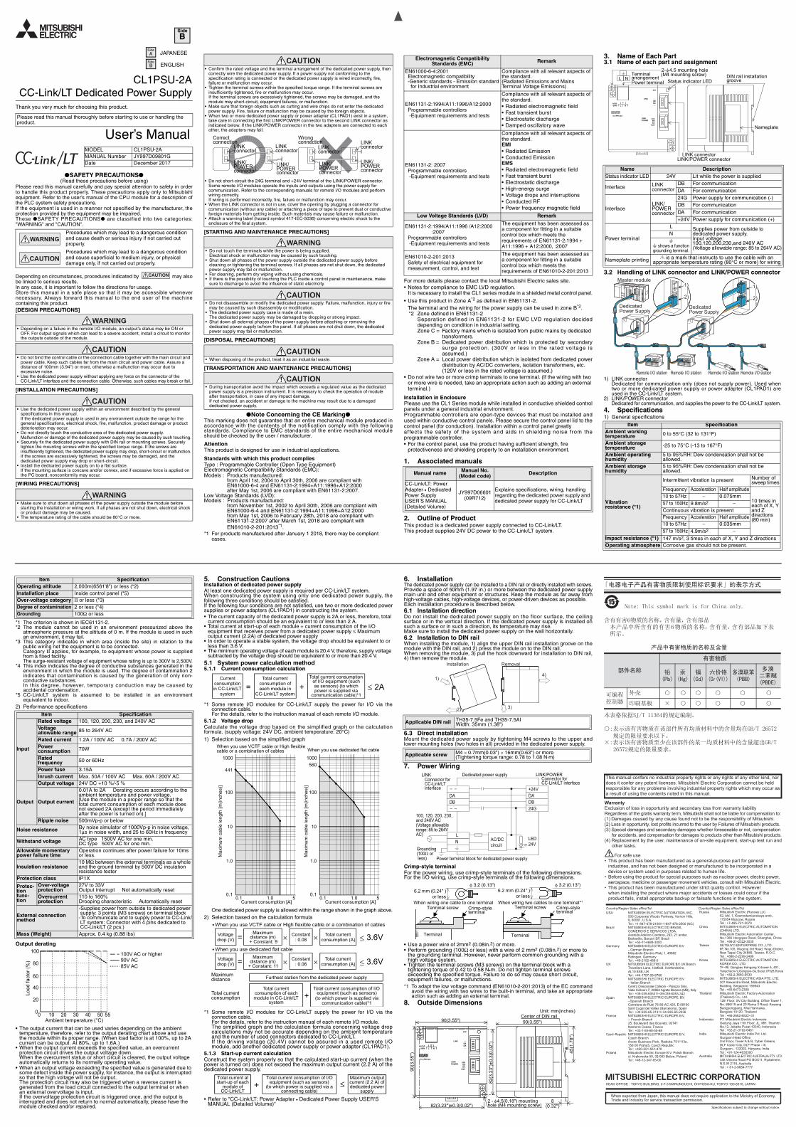
Note: This symbol mark is for China only.
含有有害6物质的名称,含有量,含有部品
本产品中所含有的有害6物质的名称,含有量,含有部品如下表所示。
产品中有害物质的名称及含量
本表格依据SJ/T 11364的规定编制。
:表示该有害物质在该部件所有均质材料中的含量均在GB/T 26572 规定的限量要求以下。
×:表示该有害物质至少在该部件的某一均质材料中的含量超出GB/T 26572规定的限量要求。
部件名称
有害物质
铅(Pb)
汞(Hg)
镉(Cd)
六价铬(Cr(VI))
多溴联苯(PBB)
多溴二苯醚(PBDE)
可编程控制器
外壳
印刷基板
×
「电器电子产品有害物质限制使用标识要求」的表示方式
Note: This symbol mark is for China only.
「电器电子产品有害物质限制使用标识要求」的表示方式
SideA
Side
B
JAPANESE
SideB ENGLISH
SAFETY PRECAUTIONS(Read these precautions before using)
Please read this manual carefully and pay special attention to safety in orderto handle this product properly. These precautions apply only to Mitsubishiequipment. Refer to the user’s manual of the CPU module for a description ofthe PLC system safety precautions.If the equipment is used in a manner not specified by the manufacturer, theprotection provided by the equipment may be impaired.These SAFETY PRECAUTIONS are classified into two categories:"WARNING" and "CAUTION".
Depending on circumstances, procedures indicated by may alsobe linked to serious results.In any case, it is important to follow the directions for usage.Store this manual in a safe place so that it may be accessible whenevernecessary. Always forward this manual to the end user of the machinecontaining this product.[DESIGN PRECAUTIONS]
[INSTALLATION PRECAUTIONS]
[WIRING PRECAUTIONS]
Procedures which may lead to a dangerous condition and cause death or serious injury if not carried out properly.
Procedures which may lead to a dangerous condition and cause superficial to medium injury, or physical damage only, if not carried out properly.
• Depending on a failure in the remote I/O module, an output's status may be ON or OFF. For output signals which can lead to a severe accident, install a circuit to monitor the outputs outside of the module.
• Do not bind the control cable or the connection cable together with the main circuit and power cable. Keep such cables far from the main circuit and power cable. Assure a distance of 100mm (3.94") or more, otherwise a malfunction may occur due to excessive noise.
• Use the dedicated power supply without applying any force on the connector of the CC-Link/LT interface and the connection cable. Otherwise, such cables may break or fail.
• Use the dedicated power supply within an environment described by the general specifications in this manual. If the dedicated power supply is used in any environment outside the range for the general specifications, electrical shock, fire, malfunction, product damage or product deterioration may occur.
• Do not directly touch the conductive area of the dedicated power supply.Malfunction or damage of the dedicated power supply may be caused by such touching.
• Securely fix the dedicated power supply with DIN rail or mounting screws. Securely tighten the mounting screws within the specified torque range. If the screws are insufficiently tightened, the dedicated power supply may drop, short-circuit or malfunction.If the screws are excessively tightened, the screws may be damaged, and the dedicated power supply may drop or short-circuit.
• Install the dedicated power supply on to a flat surface.If the mounting surface is concave and/or convex, and if excessive force is applied on the PC board, nonconformity may occur.
• Make sure to shut down all phases of the power supply outside the module before starting the installation or wiring work. If all phases are not shut down, electrical shock or product damage may be caused.
• The temperature rating of the cable should be 80°C or more.
[STARTING AND MAINTENANCE PRECAUTIONS]
[DISPOSAL PRECAUTIONS]
[TRANSPORTATION AND MAINTENANCE PRECAUTIONS]
Note Concerning the CE MarkingThis marking does not guarantee that an entire mechanical module produced inaccordance with the contents of the notification comply with the followingstandards. Compliance to EMC standards of the entire mechanical moduleshould be checked by the user / manufacturer.
AttentionThis product is designed for use in industrial applications.
Standards with which this product compliesType : Programmable Controller (Open Type Equipment)Electromagnetic Compatibility Standards (EMC):Models : Products manufactured:
from April 1st, 2004 to April 30th, 2006 are compliant withEN61000-6-4 and EN61131-2:1994+A11:1996+A12:2000after May 1st, 2006 are compliant with EN61131-2:2007.
Low Voltage Standards (LVD):Models : Products manufactured:
from November 1st, 2002 to April 30th, 2006 are compliant with EN61000-6-4 and EN61131-2:1994+A11:1996+A12:2000from May 1st, 2006 to February 28th, 2018 are compliant with EN61131-2:2007 after March 1st, 2018 are compliant with EN61010-2-201:2013*1.
*1 For products manufactured after January 1 2018, there may be compliant cases.
• Confirm the rated voltage and the terminal arrangement of the dedicated power supply, then correctly wire the dedicated power supply. If a power supply not conforming to the specification rating is connected or the dedicated power supply is wired incorrectly, fire, failure or malfunction may occur.
• Tighten the terminal screws within the specified torque range. If the terminal screws are insufficiently tightened, fire or malfunction may occur.If the terminal screws are excessively tightened, the screws may be damaged, and the module may short-circuit, equipment failures, or malfunction.
• Make sure that foreign objects such as cutting and wire chips do not enter the dedicated power supply. Fire, failure or malfunction may be caused by the foreign objects.
• When two or more dedicated power supply or power adapter (CL1PAD1) exist in a system, take care in connecting the first LINK/POWER connector to the second LINK connector as indicated below. If the LINK/POWER connector in the two adapters are connected to each other, the adapters may fail.
• Do not short-circuit the 24G terminal and +24V terminal of the LINK/POWER connector. Some remote I/O modules operate the inputs and outputs using the power supply for communication. Refer to the corresponding manuals for remote I/O modules and perform wiring correctly.If wiring is performed incorrectly, fire, failure or malfunction may occur.
• When the LINK connector is not in use, cover the opening by plugging a connector for communication (without any cable) or attaching a piece of tape to prevent dust or conductive foreign materials from getting inside. Such materials may cause failure or malfunction.
• Attach a warning label (hazard symbol 417-IEC-5036) concerning electric shock to the enclosure of the final system.
• Do not touch the terminals while the power is being supplied.Electrical shock or malfunction may be caused by such touching.
• Shut down all phases of the power supply outside the dedicated power supply before cleaning or tightening the terminal screws. If all phases are not shut down, the dedicated power supply may fail or malfunction.
• For cleaning, perform dry wiping without using chemicals.• If there is the possibility of touching the PLC inside a control panel in maintenance, make
sure to discharge to avoid the influence of static electricity.
• Do not disassemble or modify the dedicated power supply. Failure, malfunction, injury or fire may be caused by such disassembly or modification.
• The dedicated power supply case is made of a resin.The dedicated power supply may be damaged by dropping or strong impact.
• Shut down all external phases of the power supply before attaching or removing the dedicated power supply to/from the panel. If all phases are not shut down, the dedicated power supply may fail or malfunction.
Correctconnection
LINKconnector
LINKconnector
LINK/POWERconnector
Wrongconnection
LINKconnector
LINK/POWERconnector
LINKconnector
LINK/POWERconnector
LINK/POWERconnector
• When disposing of the product, treat it as an industrial waste.
• During transportation avoid the impact which exceeds a regulated value as the dedicated power supply is a precision instrument. It is necessary to check the operation of module after transportation, in case of any impact damage. If not checked, an accident or damage to the machine may result due to a damaged dedicated power supply.
.
For more details please contact the local Mitsubishi Electric sales site.• Notes for compliance to EMC LVD regulation.
It is necessary to install the CL1 series module in a shielded metal control panel.
• Use this product in Zone A*2 as defined in EN61131-2.The terminal and the wiring for the power supply can be used in zone B*2.*2 Zone defined in EN61131-2
Separation defined in EN61131-2 for EMC LVD regulation decideddepending on condition in industrial setting.Zone C = Factory mains which is isolated from public mains by dedicated
transformers.Zone B = Dedicated power distribution which is protected by secondary
surge protection. (300V or less in the rated voltage isassumed.)
Zone A = Local power distribution which is isolated from dedicated powerdistribution by AC/DC converters, isolation transformers, etc. (120V or less in the rated voltage is assumed.)
• Do not wire two or more crimp terminals to one terminal. (If the wiring with two or more wire is needed, take an appropriate action such as adding an external terminal.)
Installation in EnclosurePlease use the CL1 Series module while installed in conductive shielded controlpanels under a general industrial environment.Programmable controllers are open-type devices that must be installed andused within conductive control panels. Please secure the control panel lid to thecontrol panel (for conduction). Installation within a control panel greatlyaffects the safety of the system and aids in shielding noise from theprogrammable controller.• For the control panel, use the product having sufficient strength, fire
protectiveness and shielding property to an installation environment.
1. Associated manuals
2. Outline of ProductThis product is a dedicated power supply connected to CC-Link/LT.This product supplies 24V DC power to the CC-Link/LT system.
Electromagnetic Compatibility Standards (EMC) Remark
EN61000-6-4:2001Electromagnetic compatibility-Generic standards - Emission standard for Industrial environment
Compliance with all relevant aspects of the standard.(Radiated Emissions and Mains Terminal Voltage Emissions)
EN61131-2:1994/A11:1996/A12:2000Programmable controllers -Equipment requirements and tests
Compliance with all relevant aspects of the standard.• Radiated electromagnetic field• Fast transient burst• Electrostatic discharge• Damped oscillatory wave
EN61131-2: 2007Programmable controllers -Equipment requirements and tests
Compliance with all relevant aspects of the standard.EMI• Radiated Emission• Conducted EmissionEMS• Radiated electromagnetic field• Fast transient burst• Electrostatic discharge• High-energy surge• Voltage drops and interruptions• Conducted RF• Power frequency magnetic field
Low Voltage Standards (LVD) Remark
EN61131-2:1994/A11:1996 /A12:2000:2007
Programmable controllers -Equipment requirements and tests
The equipment has been assessed as a component for fitting in a suitable control box which meets the requirements of EN61131-2:1994 + A11:1996 + A12:2000, :2007
EN61010-2-201:2013Safety of electrical equipment for measurement, control, and test
The equipment has been assessed as a component for fitting in a suitable control box which meets the requirements of EN61010-2-201:2013
Manual name Manual No.(Model code) Description
CC-Link/LT: Power Adapter • Dedicated Power SupplyUSER’S MANUAL(Detailed Volume)
JY997D06601(09R712)
Explains specifications, wiring, handling regarding the dedicated power supply and dedicated power supply for CC-Link/LT
3. Name of Each Part3.1 Name of each part and assignment
3.2 Handling of LINK connector and LINK/POWER connector
1) LINK connectorDedicated for communication only (does not supply power). Used whentwo or more dedicated power supply or power adapter (CL1PAD1) areused in the CC-Link/LT system.
2) LINK/POWER connectorDedicated for communication, and supplies the power to the CC-Link/LT system.
4. Specifications1) General specifications
CL1PSU-2A
AC85-264V
24V
LINK - -DBDA- -
LINK/POWER
24GDBDA
+24V
L N
DIN rail installationgroove
Nameplate
LINK connectorLINK/POWER connector
Status indicator LEDPower terminal
2-φ4.5 mounting hole(M4 mounting screw)Terminal
arrangementL N
Name DescriptionStatus indicator LED 24V Lit while the power is supplied
Interface LINK connector
DB For communicationDA For communication
InterfaceLINK/POWER connector
24G Power supply for communication (-)DB For communicationDA For communication+24V Power supply for communication (+)
Power terminal
L Supplies power from outside to dedicated power supply.Input voltage:100,120,200,230,and 240V AC(Voltage allowable range: 85 to 264V AC)
N
shows a function grounding terminal.
Nameplate printing is a mark that instructs to use the cable with an appropriate temperature rating (80°C or more) for wiring
Item SpecificationAmbient working temperature 0 to 55°C (32 to 131°F)
Ambient storage temperature -25 to 75°C (-13 to 167°F)
Ambient operating humidity
5 to 95%RH: Dew condensation shall not be allowed.
Ambient storage humidity
5 to 95%RH: Dew condensation shall not be allowed.
Vibration resistance (*1)
Intermittent vibration is present Number of sweep times
Frequency Acceleration Half amplitude
10 times in each of X, Y and Z directions (80 min)
10 to 57Hz − 0.075mm57 to 150Hz 9.8m/s2 −Continuous vibration is presentFrequency Acceleration Half amplitude10 to 57Hz − 0.035mm57 to 150Hz 4.9m/s2 −
Impact resistance (*1) 147 m/s2, 3 times in each of X, Y and Z directionsOperating atmosphere Corrosive gas should not be present.
COMM.
1
COMM.
1
Master module
DedicatedPower Supply
1)
2)
1)
2)
DedicatedPower Supply
Remote I/O stationRemote I/O stationRemote I/O stationRemote I/O station
*1 The criterion is shown in IEC61131-2.*2 The module cannot be used in an environment pressurized above the
atmospheric pressure at the altitude of 0 m. If the module is used in suchan environment, it may fail.
*3 This category indicates in which area (inside the site) in relation to thepublic wiring net the equipment is to be connected.Category ΙΙ applies, for example, to equipment whose power is suppliedfrom a fixed facility.The surge-resistant voltage of equipment whose rating is up to 300V is 2,500V.
*4 This index indicates the degree of conductive substances generated in theenvironment in which the module is used. The degree of contamination 2indicates that contamination is caused by the generation of only non-conductive substances.In this degree, however, temporary conduction may be caused byaccidental condensation.
*5 CC-Link/LT system is assumed to be installed in an environmentequivalent to indoor.
2) Performance specifications
Operating altitude 2,000m(6561'8") or less (*2)Installation place Inside control panel (*5)Over-voltage category ΙΙ or less (*3)Degree of contamination 2 or less (*4)Grounding 100Ω or less
Item Specification
Item SpecificationRated voltage 100, 120, 200, 230, and 240V ACVoltage
5. Construction CautionsInstallation of dedicated power supplyAt least one dedicated power supply is required per CC-Link/LT system.When constructing the system using only one dedicated power supply, thefollowing three conditions should be satisfied.If the following four conditions are not satisfied, use two or more dedicated power
6. InstallationThe dedicated power supply can be installed to a DIN rail or directly installed with screws.Provide a space of 50mm (1.97 in.) or more between the dedicated power supplymain unit and other equipment or structures. Keep the module as far away fromhigh-voltage cables, high-voltage devices, or power-driven devices as possible. Each installation procedure is described below.
Thank you very much for choosing this product.
CL1PSU-2ACC-Link/LT Dedicated Power Supply
Please read this manual thoroughly before starting to use or handling the product.
User’s ManualMODEL CL1PSU-2AMANUAL Number JY997D09801GDate December 2017
Output derating
• The output current that can be used varies depending on the ambient temperature, therefore, refer to the output derating chart above and use the module within its proper range. (When load factor is at 100%, up to 2A current can be output. At 80%, up to 1.6A.)
• When the output current exceeds the specified value, an overcurrent protection circuit drives the output voltage down.When the overcurrent status or short circuit is cleared, the output voltage automatically returns to its normally operating value.
• When an output voltage exceeding the specified value is generated due to some defect inside the power supply, for instance, the output is interrupted so that the high voltage will not be output.The protection circuit may also be triggered when a reverse current is generated from the load circuit connected to the output terminal or when an external overvoltage is input.If the overvoltage protection circuit is triggered once, and the output is interrupted and does not return to normal automatically, please have the module checked and/or repaired.
Input
allowable range 85 to 264V AC
Rated current 1.2A / 100V AC 0.7A / 200V ACPower consumption 70W
Rated frequency 50 or 60Hz
Power fuse 3.15AInrush current Max. 50A / 100V AC Max. 60A / 200V AC
Output
Output voltage 24V DC +10 %/-5 %
Output current
0.01A to 2A Derating occurs according to the ambient temperature and power voltage.[Use the module in a proper range so that the total current consumption of each module does not exceed 2A (except the period immediately after the power is turned on).]
Ripple noise 500mVp-p or below
Noise resistance By noise simulator of 1000Vp-p in noise voltage, 1µs in noise width, and 25 to 60Hz in frequency
Withstand voltage AC type 1500V AC for one min.DC type 500V AC for one min.
Allowable momentary power failure time
Operation continues after power failure for 10ms or less.
Insulation resistance10 MΩ between the external terminals as a whole and the ground terminal by 500V DC insulation resistance tester
Protection class IP1X
Protec-tion func-tion
Over-voltage protection
27V to 33V Output interrupt Not automatically reset
Overcurrent protection
110 to 160%Drooping characteristic Automatically reset
External connection method
-Supplies power from outside to dedicated power supply: 3 points (M3 screws) on terminal block
-To communicate and to supply power to CC-Link/LT system: Connector with 4 pins dedicated to CC-Link/LT (2 pcs.)
Mass (Weight) Approx. 0.4 kg (0.88 lbs)
Ambient temperature (°C)
Load
fact
or (%
)
0
20
40
60
80
100
0 10 20 30 40 50 55
100V AC or higher90V AC85V AC
supplies or power adapters (CL1PAD1) in constructing the system.• The current capacity of the dedicated power supply is 2A or less, therefore, total
current consumption should be an equivalent to or less than 2 A.• Total current at start-up of each module + current consumption of the I/O
equipment that receives power from a dedicated power supply ≤ Maximum output current (2.2A) of dedicated power supply
• In order to operate a stable system, the voltage drop should be equivalent to or less than 3.6 V.
• The minimum operating voltage of each module is 20.4 V, therefore, supply voltage subtracted by the voltage drop should be equivalent to or more than 20.4 V.
5.1 System power calculation method5.1.1 Current consumption calculation
*1 Some remote I/O modules for CC-Link/LT supply the power for I/O via theconnection cable.For the details, refer to the instruction manual of each remote I/O module.
5.1.2 Voltage dropCalculate the voltage drop based on the simplified graph or the calculationformula. (supply voltage: 24V DC, ambient temperature: 20°C)1) Selection based on the simplified graph
One dedicated power supply is allowed within the range shown in the graph above.2) Selection based on the calculation formula
*1 Some remote I/O modules for CC-Link/LT supply the power for I/O via theconnection cable.For the details, refer to the instruction manual of each remote I/O module. The simplified graph and the calculation formula concerning voltage dropcalculations may not be accurate depending on the ambient temperatureand the number of used connectors dedicated to CC-Link/LT.If the driving voltage (20.4V) cannot be assured in a used remote I/Omodule, add another dedicated power supply or power adapter (CL1PAD1).
5.1.3 Start-up current calculationConstruct the system properly so that the calculated start-up current (when thepower is turned on) does not exceed the maximum output current (2.2 A) of thededicated power supply.
• Refer to "CC-Link/LT: Power Adapter • Dedicated Power Supply USER'S MANUAL (Detailed Volume)"
Currentconsumptionin CC-Link/LT
system
Total currentconsumption ofeach module in
CC-Link/LT system
Total current consumptionof I/O equipment (suchas sensors) (to whichpower is supplied via
communication cable)*1= + ≤ 2A
0.10.1
1.0
10
100
560
1.0 5Current consumption [A]
1000
0.10.1
1.0
10
100
441
1.0 5Current consumption [A]
1000
When you use VCTF cable or High flexiblecable or a combination of cables When you use dedicated flat cable
Max
imum
cab
le le
ngth
[m(in
ches
)]
Max
imum
cab
le le
ngth
[m(in
ches
)]
Voltagedrop (V)
Maximumdistance (m)
+ Constant: 9Constant
: 0.08= × ≤ 3.6V× Total currentconsumption (A)
Maximumdistance
Total currentconsumption
Furthest station from the dedicated power supply
Total currentconsumption of eachmodule in CC-Link/LT
system+
Total current consumption of I/Oequipment (such as sensors)
(to which power is supplied viacommunication cable)*1
Voltagedrop (V)
Maximumdistance (m)
+ Constant: 11Constant
: 0.06= × ≤ 3.6V× Total currentconsumption (A)
When you use VCTF cable or High flexible cable or a combination of cables
When you use dedicated flat cable
Total current atstart-up of each
module ofCC-Link/LT
≤+Total current consumption of I/O
equipment (such as sensors)(to which power is supplied via a
connecting cable)
Maximum outputcurrent (2.2 A) ofdedicated power
supply
6.1 Installation directionDo not install the dedicated power supply on the floor surface, the ceilingsurface or in the vertical direction. If the dedicated power supply is installed onsuch a surface or in such a direction, its temperature may rise.Make sure to install the dedicated power supply on the wall horizontally.6.2 Installation to DIN railWhen installing the module, 1) align the upper DIN rail installation groove on themodule with the DIN rail, and 2) press the module on to the DIN rail.When removing the module, 3) pull the hook downward for installation to DIN rail,4) then remove the module.
6.3 Direct installationMount the dedicated power supply by tightening M4 screws to the upper andlower mounting holes (two holes in all) provided in the dedicated power supply.
7. Power Wiring
Crimp-style terminalFor the power wiring, use crimp-style terminals of the following dimensions.For the I/O wiring, use crimp-style terminals of the following dimensions.
• Use a power wire of 2mm2 (0.08in.2) or more.• Perform grounding (100Ω or less) with a wire of 2 mm2 (0.08in.2) or more to
the grounding terminal. However, never perform common grounding with a high voltage system.
• Tighten the terminal screws (M3 screws) on the terminal block with a tightening torque of 0.42 to 0.58 N•m. Do not tighten terminal screws exceeding the specified torque. Failure to do so may cause short circuit, equipment failures, or malfunctions.
*1 To adapt the low voltage command (EN61010-2-201:2013) of the EC commandavoid the wiring with two wires to the built-in terminal, and take an appropriateaction such as adding an external terminal.
8. Outside Dimensions
Applicable DIN rail TH35-7.5Fe and TH35-7.5AIWidth: 35mm (1.38")
Applicable screw M4 × 0.7mm(0.03") × 16mm(0.63") or more(Tightening torque range: 0.78 to 1.08 N⋅m)
1)
Installation Removal
2) 3)
4)
Connector forCC-Link/LTinterface
DADB
Connector forCC-Link/LT interface
Power terminal block for dedicated power supply
Grounding(100Ω or less)
+24VDA
24GDB
LINK LINK/POWER
NL
Dedicated power supply
100, 120, 200, 230, and 240V AC (Voltage allowable range: 85 to 264V AC)
AC/DC circuit
LED24V
6.2 mm (0.24" )or less
6.2 mm (0.24" )or less
Terminal
Terminal screw Crimp-styleterminal
Terminal screw Crimp-styleterminal
When wiring one cable to one terminal When wiring two cables to one terminal*1
Terminal
φ 3.2 (0.13") φ 3.2 (0.13")
CL1PSU-2A
AC85-264V
24V
LINK - -DBDA- -
LINK/POWER
24GDBDA
+24V
L N
Center of DIN rail
2 - φ4.5(0.18") mountinghole (M4 mounting screw)
90(3.55")
45(1
.78"
)
Unit: mm(inches)
8(0.32")82(3.23")±0.3(0.02")
90(3
.55"
)
82(3
.23"
)±0.
3(0.
02")
90(3.55")
Specifications subject to change without notice.
HEAD OFFICE : TOKYO BUILDING, 2-7-3 MARUNOUCHI, CHIYODA-KU, TOKYO 100-8310, JAPAN
When exported from Japan, this manual does not require application to the Ministry of Economy, Trade and Industry for service transaction permission.
This manual confers no industrial property rights or any rights of any other kind, nor does it confer any patent licenses. Mitsubishi Electric Corporation cannot be held responsible for any problems involving industrial property rights which may occur as a result of using the contents noted in this manual.
WarrantyExclusion of loss in opportunity and secondary loss from warranty liabilityRegardless of the gratis warranty term, Mitsubishi shall not be liable for compensation to:(1) Damages caused by any cause found not to be the responsibility of Mitsubishi.(2) Loss in opportunity, lost profits incurred to the user by Failures of Mitsubishi products.(3) Special damages and secondary damages whether foreseeable or not, compensation for accidents, and compensation for damages to products other than Mitsubishi products.(4) Replacement by the user, maintenance of on-site equipment, start-up test run and other tasks.
• This product has been manufactured as a general-purpose part for generalindustries, and has not been designed or manufactured to be incorporated in a device or system used in purposes related to human life.
• Before using the product for special purposes such as nuclear power, electric power, aerospace, medicine or passenger movement vehicles, consult with Mitsubishi Electric.
• This product has been manufactured under strict quality control. Howeverwhen installing the product where major accidents or losses could occur if theproduct fails, install appropriate backup or failsafe functions in the system.
For safe use
Country/Region Sales office/TelUSA MITSUBISHI ELECTRIC AUTOMATION, INC.
500 Corporate Woods Parkway, Vernon Hills, IL 60061, U.S.A.Tel : +1-847-478-2100/+1-847-478-2500 (NC)
Brazil MITSUBISHI ELECTRIC DO BRASIL COMERCIO E SERVICOS LTDA. Avenida Adelino Cardana, 293, 21 andar, Bethaville, Barueri SP, Brazil Tel : +55-11-4689-3000
Germany MITSUBISHI ELECTRIC EUROPE B.V. – German BranchMitsubishi-Electric-Platz 1, 40882 Ratingen, GermanyTel : +49-2102-486-0
UK MITSUBISHI ELECTRIC EUROPE B.V. UK BranchTravellers Lane, Hatfield, Hertfordshire, AL10 8XB, UKTel : +44-1707-28-8780
Italy MITSUBISHI ELECTRIC EUROPE B.V. – Italian BranchCentro Direzionale Colleoni - Palazzo Sirio, Viale Colleoni 7, 20864 Agrate Brianza (MB), ItalyTel : +39-039-60531/+39-039-6053-342
Spain MITSUBISHI ELECTRIC EUROPE, B.V. – Spanish BranchCarretera de Rubi 76-80-AC.420, E-08190 Sant Cugat del Valles (Barcelona), Spain Tel : +34-935-65-3131/+34-935-65-2236
France MITSUBISHI ELECTRIC EUROPE B.V. – French Branch25, Boulevard des Bouvets, 92741 Nanterre Cedex, FranceTel : +33-1-55-68-55-68
Czech Republic MITSUBISHI ELECTRIC EUROPE B.V. Czech BranchAvenir Business Park, Radicka 751/113e, 158 00 Praha5, Czech RepublicTel : +420-251-551-470
Poland Mitsubishi Electric Europe B.V. Polish Branchul. Krakowska 50, 32-083 Balice, PolandTel : +48-12-347-65-00
Country/Region Sales office/TelRussia
China MITSUBISHI ELECTRIC AUTOMATION (CHINA) LTD.Mitsubishi Electric Automation Center, No.1386 Hongqiao Road, Shanghai, ChinaTel : +86-21-2322-3030
Taiwan SETSUYO ENTERPRISE CO., LTD.6F, No.105, Wugong 3rd Road, Wugu District, New Taipei City 24889, Taiwan, R.O.C.Tel : +886-2-2299-2499
Korea MITSUBISHI ELECTRIC AUTOMATION KOREA CO., LTD.7F~9F, Gangseo Hangang Xi-tower A, 401, Yangcheon-ro, Gangseo-Gu, Seoul, 07528, KoreaTel : +82-2-3660-9530
Singapore MITSUBISHI ELECTRIC ASIA PTE. LTD, 307 Alexandra Road, Mitsubishi Electric Building, Singapore 159943 Tel : +65-6473-2308
Thailand Mitsubishi Electric Factory Automation (Thailand) Co., Ltd.12th Floor, SV.City Building, Office Tower 1, No. 896/19 and 20 Rama 3 Road, Kwaeng Bangpongpang, Khet Yannawa, Bangkok 10120, ThailandTel : +66-2682-6522~31
Indonesia PT. Mitsubishi Electric IndonesiaGedung Jaya 11th Floor, JL. MH. ThamrinNo.12, Jakarta Pusat 10340, IndonesiaTel : +62-21-3192-6461
India Mitsubishi Electric India Pvt. Ltd. Gurgaon Head Office2nd Floor, Tower A & B, Cyber Greens, DLF Cyber City, DLF Phase - III, Gurgaon - 122002, Haryana, IndiaTel : +91-124-4630300
Australia MITSUBISHI ELECTRIC AUSTRALIA PTY. LTD.348 Victoria Road PO BOX11, Rydalmere, N.S.W 2116, Australia Tel : + 61-2-9684-7777
Mitsubishi Electric (Russia) LLC52, bld. 1, Kosmodamianskaya emb., 115054 Moscow, RussiaTel : +7-495-721-2070
含有有害6物质的名称,含有量,含有部品
本产品中所含有的有害6物质的名称,含有量,含有部品如下表所示。
产品中有害物质的名称及含量
本表格依据SJ/T 11364的规定编制。
:表示该有害物质在该部件所有均质材料中的含量均在GB/T 26572 规定的限量要求以下。
×:表示该有害物质至少在该部件的某一均质材料中的含量超出GB/T 26572规定的限量要求。
部件名称
有害物质
铅(Pb)
汞(Hg)
镉(Cd)
六价铬(Cr(VI))
多溴联苯(PBB)
多溴二苯醚(PBDE)
可编程控制器
外壳
印刷基板
×
Specifications subject to change without notice.
HEAD OFFICE : TOKYO BUILDING, 2-7-3 MARUNOUCHI, CHIYODA-KU, TOKYO 100-8310, JAPAN
When exported from Japan, this manual does not require application to the Ministry of Economy, Trade and Industry for service transaction permission.
This manual confers no industrial property rights or any rights of any other kind, nor does it confer any patent licenses. Mitsubishi Electric Corporation cannot be held responsible for any problems involving industrial property rights which may occur as a result of using the contents noted in this manual.
WarrantyExclusion of loss in opportunity and secondary loss from warranty liabilityRegardless of the gratis warranty term, Mitsubishi shall not be liable for compensation to:(1) Damages caused by any cause found not to be the responsibility of Mitsubishi.(2) Loss in opportunity, lost profits incurred to the user by Failures of Mitsubishi products.(3) Special damages and secondary damages whether foreseeable or not, compensation for accidents, and compensation for damages to products other than Mitsubishi products.(4) Replacement by the user, maintenance of on-site equipment, start-up test run and other tasks.
• This product has been manufactured as a general-purpose part for generalindustries, and has not been designed or manufactured to be incorporated in a device or system used in purposes related to human life.
• Before using the product for special purposes such as nuclear power, electric power, aerospace, medicine or passenger movement vehicles, consult with Mitsubishi Electric.
• This product has been manufactured under strict quality control. Howeverwhen installing the product where major accidents or losses could occur if theproduct fails, install appropriate backup or failsafe functions in the system.
For safe use
Country/Region Sales office/TelUSA MITSUBISHI ELECTRIC AUTOMATION, INC.
500 Corporate Woods Parkway, Vernon Hills, IL 60061, U.S.A.Tel : +1-847-478-2100/+1-847-478-2500 (NC)
Brazil MITSUBISHI ELECTRIC DO BRASIL COMERCIO E SERVICOS LTDA. Avenida Adelino Cardana, 293, 21 andar, Bethaville, Barueri SP, Brazil Tel : +55-11-4689-3000
Germany MITSUBISHI ELECTRIC EUROPE B.V. – German BranchMitsubishi-Electric-Platz 1, 40882 Ratingen, GermanyTel : +49-2102-486-0
UK MITSUBISHI ELECTRIC EUROPE B.V. UK BranchTravellers Lane, Hatfield, Hertfordshire, AL10 8XB, UKTel : +44-1707-28-8780
Italy MITSUBISHI ELECTRIC EUROPE B.V. – Italian BranchCentro Direzionale Colleoni - Palazzo Sirio, Viale Colleoni 7, 20864 Agrate Brianza (MB), ItalyTel : +39-039-60531/+39-039-6053-342
Spain MITSUBISHI ELECTRIC EUROPE, B.V. – Spanish BranchCarretera de Rubi 76-80-AC.420, E-08190 Sant Cugat del Valles (Barcelona), Spain Tel : +34-935-65-3131/+34-935-65-2236
France MITSUBISHI ELECTRIC EUROPE B.V. – French Branch25, Boulevard des Bouvets, 92741 Nanterre Cedex, FranceTel : +33-1-55-68-55-68
Czech Republic MITSUBISHI ELECTRIC EUROPE B.V. Czech BranchAvenir Business Park, Radicka 751/113e, 158 00 Praha5, Czech RepublicTel : +420-251-551-470
Poland Mitsubishi Electric Europe B.V. Polish Branchul. Krakowska 50, 32-083 Balice, PolandTel : +48-12-347-65-00
Country/Region Sales office/TelRussia
China MITSUBISHI ELECTRIC AUTOMATION (CHINA) LTD.Mitsubishi Electric Automation Center, No.1386 Hongqiao Road, Shanghai, ChinaTel : +86-21-2322-3030
Taiwan SETSUYO ENTERPRISE CO., LTD.6F, No.105, Wugong 3rd Road, Wugu District, New Taipei City 24889, Taiwan, R.O.C.Tel : +886-2-2299-2499
Korea MITSUBISHI ELECTRIC AUTOMATION KOREA CO., LTD.7F~9F, Gangseo Hangang Xi-tower A, 401, Yangcheon-ro, Gangseo-Gu, Seoul, 07528, KoreaTel : +82-2-3660-9530
Singapore MITSUBISHI ELECTRIC ASIA PTE. LTD, 307 Alexandra Road, Mitsubishi Electric Building, Singapore 159943 Tel : +65-6473-2308
Thailand Mitsubishi Electric Factory Automation (Thailand) Co., Ltd.12th Floor, SV.City Building, Office Tower 1, No. 896/19 and 20 Rama 3 Road, Kwaeng Bangpongpang, Khet Yannawa, Bangkok 10120, ThailandTel : +66-2682-6522~31
Indonesia PT. Mitsubishi Electric IndonesiaGedung Jaya 11th Floor, JL. MH. ThamrinNo.12, Jakarta Pusat 10340, IndonesiaTel : +62-21-3192-6461
India Mitsubishi Electric India Pvt. Ltd. Gurgaon Head Office2nd Floor, Tower A & B, Cyber Greens, DLF Cyber City, DLF Phase - III, Gurgaon - 122002, Haryana, IndiaTel : +91-124-4630300
Australia MITSUBISHI ELECTRIC AUSTRALIA PTY. LTD.348 Victoria Road PO BOX11, Rydalmere, N.S.W 2116, Australia Tel : + 61-2-9684-7777
Mitsubishi Electric (Russia) LLC52, bld. 1, Kosmodamianskaya emb., 115054 Moscow, RussiaTel : +7-495-721-2070
Note: This symbol mark is for China only.
含有有害6物质的名称,含有量,含有部品
本产品中所含有的有害6物质的名称,含有量,含有部品如下表所示。
产品中有害物质的名称及含量
本表格依据SJ/T 11364的规定编制。
:表示该有害物质在该部件所有均质材料中的含量均在GB/T 26572 规定的限量要求以下。
×:表示该有害物质至少在该部件的某一均质材料中的含量超出GB/T 26572规定的限量要求。
部件名称
有害物质
铅(Pb)
汞(Hg)
镉(Cd)
六价铬(Cr(VI))
多溴联苯(PBB)
多溴二苯醚(PBDE)
可编程控制器
外壳
印刷基板
×
「电器电子产品有害物质限制使用标识要求」的表示方式
SideA
Side
B
JAPANESE
SideB ENGLISH
SAFETY PRECAUTIONS(Read these precautions before using)
Please read this manual carefully and pay special attention to safety in orderto handle this product properly. These precautions apply only to Mitsubishiequipment. Refer to the user’s manual of the CPU module for a description ofthe PLC system safety precautions.If the equipment is used in a manner not specified by the manufacturer, theprotection provided by the equipment may be impaired.These SAFETY PRECAUTIONS are classified into two categories:"WARNING" and "CAUTION".
Depending on circumstances, procedures indicated by may alsobe linked to serious results.In any case, it is important to follow the directions for usage.Store this manual in a safe place so that it may be accessible whenevernecessary. Always forward this manual to the end user of the machinecontaining this product.[DESIGN PRECAUTIONS]
[INSTALLATION PRECAUTIONS]
[WIRING PRECAUTIONS]
Procedures which may lead to a dangerous condition and cause death or serious injury if not carried out properly.
Procedures which may lead to a dangerous condition and cause superficial to medium injury, or physical damage only, if not carried out properly.
• Depending on a failure in the remote I/O module, an output's status may be ON or OFF. For output signals which can lead to a severe accident, install a circuit to monitor the outputs outside of the module.
• Do not bind the control cable or the connection cable together with the main circuit and power cable. Keep such cables far from the main circuit and power cable. Assure a distance of 100mm (3.94") or more, otherwise a malfunction may occur due to excessive noise.
• Use the dedicated power supply without applying any force on the connector of the CC-Link/LT interface and the connection cable. Otherwise, such cables may break or fail.
• Use the dedicated power supply within an environment described by the general specifications in this manual. If the dedicated power supply is used in any environment outside the range for the general specifications, electrical shock, fire, malfunction, product damage or product deterioration may occur.
• Do not directly touch the conductive area of the dedicated power supply.Malfunction or damage of the dedicated power supply may be caused by such touching.
• Securely fix the dedicated power supply with DIN rail or mounting screws. Securely tighten the mounting screws within the specified torque range. If the screws are insufficiently tightened, the dedicated power supply may drop, short-circuit or malfunction.If the screws are excessively tightened, the screws may be damaged, and the dedicated power supply may drop or short-circuit.
• Install the dedicated power supply on to a flat surface.If the mounting surface is concave and/or convex, and if excessive force is applied on the PC board, nonconformity may occur.
• Make sure to shut down all phases of the power supply outside the module before starting the installation or wiring work. If all phases are not shut down, electrical shock or product damage may be caused.
• The temperature rating of the cable should be 80°C or more.
[STARTING AND MAINTENANCE PRECAUTIONS]
[DISPOSAL PRECAUTIONS]
[TRANSPORTATION AND MAINTENANCE PRECAUTIONS]
Note Concerning the CE MarkingThis marking does not guarantee that an entire mechanical module produced inaccordance with the contents of the notification comply with the followingstandards. Compliance to EMC standards of the entire mechanical moduleshould be checked by the user / manufacturer.
AttentionThis product is designed for use in industrial applications.
Standards with which this product compliesType : Programmable Controller (Open Type Equipment)Electromagnetic Compatibility Standards (EMC):Models : Products manufactured:
from April 1st, 2004 to April 30th, 2006 are compliant withEN61000-6-4 and EN61131-2:1994+A11:1996+A12:2000after May 1st, 2006 are compliant with EN61131-2:2007.
Low Voltage Standards (LVD):Models : Products manufactured:
from November 1st, 2002 to April 30th, 2006 are compliant with EN61000-6-4 and EN61131-2:1994+A11:1996+A12:2000from May 1st, 2006 to February 28th, 2018 are compliant with EN61131-2:2007 after March 1st, 2018 are compliant with EN61010-2-201:2013*1.
*1 For products manufactured after January 1 2018, there may be compliant cases.
• Confirm the rated voltage and the terminal arrangement of the dedicated power supply, then correctly wire the dedicated power supply. If a power supply not conforming to the specification rating is connected or the dedicated power supply is wired incorrectly, fire, failure or malfunction may occur.
• Tighten the terminal screws within the specified torque range. If the terminal screws are insufficiently tightened, fire or malfunction may occur.If the terminal screws are excessively tightened, the screws may be damaged, and the module may short-circuit, equipment failures, or malfunction.
• Make sure that foreign objects such as cutting and wire chips do not enter the dedicated power supply. Fire, failure or malfunction may be caused by the foreign objects.
• When two or more dedicated power supply or power adapter (CL1PAD1) exist in a system, take care in connecting the first LINK/POWER connector to the second LINK connector as indicated below. If the LINK/POWER connector in the two adapters are connected to each other, the adapters may fail.
• Do not short-circuit the 24G terminal and +24V terminal of the LINK/POWER connector. Some remote I/O modules operate the inputs and outputs using the power supply for communication. Refer to the corresponding manuals for remote I/O modules and perform wiring correctly.If wiring is performed incorrectly, fire, failure or malfunction may occur.
• When the LINK connector is not in use, cover the opening by plugging a connector for communication (without any cable) or attaching a piece of tape to prevent dust or conductive foreign materials from getting inside. Such materials may cause failure or malfunction.
• Attach a warning label (hazard symbol 417-IEC-5036) concerning electric shock to the enclosure of the final system.
• Do not touch the terminals while the power is being supplied.Electrical shock or malfunction may be caused by such touching.
• Shut down all phases of the power supply outside the dedicated power supply before cleaning or tightening the terminal screws. If all phases are not shut down, the dedicated power supply may fail or malfunction.
• For cleaning, perform dry wiping without using chemicals.• If there is the possibility of touching the PLC inside a control panel in maintenance, make
sure to discharge to avoid the influence of static electricity.
• Do not disassemble or modify the dedicated power supply. Failure, malfunction, injury or fire may be caused by such disassembly or modification.
• The dedicated power supply case is made of a resin.The dedicated power supply may be damaged by dropping or strong impact.
• Shut down all external phases of the power supply before attaching or removing the dedicated power supply to/from the panel. If all phases are not shut down, the dedicated power supply may fail or malfunction.
Correctconnection
LINKconnector
LINKconnector
LINK/POWERconnector
Wrongconnection
LINKconnector
LINK/POWERconnector
LINKconnector
LINK/POWERconnector
LINK/POWERconnector
• When disposing of the product, treat it as an industrial waste.
• During transportation avoid the impact which exceeds a regulated value as the dedicated power supply is a precision instrument. It is necessary to check the operation of module after transportation, in case of any impact damage. If not checked, an accident or damage to the machine may result due to a damaged dedicated power supply.
.
For more details please contact the local Mitsubishi Electric sales site.• Notes for compliance to EMC LVD regulation.
It is necessary to install the CL1 series module in a shielded metal control panel.
• Use this product in Zone A*2 as defined in EN61131-2.The terminal and the wiring for the power supply can be used in zone B*2.*2 Zone defined in EN61131-2
Separation defined in EN61131-2 for EMC LVD regulation decideddepending on condition in industrial setting.Zone C = Factory mains which is isolated from public mains by dedicated
transformers.Zone B = Dedicated power distribution which is protected by secondary
surge protection. (300V or less in the rated voltage isassumed.)
Zone A = Local power distribution which is isolated from dedicated powerdistribution by AC/DC converters, isolation transformers, etc. (120V or less in the rated voltage is assumed.)
• Do not wire two or more crimp terminals to one terminal. (If the wiring with two or more wire is needed, take an appropriate action such as adding an external terminal.)
Installation in EnclosurePlease use the CL1 Series module while installed in conductive shielded controlpanels under a general industrial environment.Programmable controllers are open-type devices that must be installed andused within conductive control panels. Please secure the control panel lid to thecontrol panel (for conduction). Installation within a control panel greatlyaffects the safety of the system and aids in shielding noise from theprogrammable controller.• For the control panel, use the product having sufficient strength, fire
protectiveness and shielding property to an installation environment.
1. Associated manuals
2. Outline of ProductThis product is a dedicated power supply connected to CC-Link/LT.This product supplies 24V DC power to the CC-Link/LT system.
Electromagnetic Compatibility Standards (EMC) Remark
EN61000-6-4:2001Electromagnetic compatibility-Generic standards - Emission standard for Industrial environment
Compliance with all relevant aspects of the standard.(Radiated Emissions and Mains Terminal Voltage Emissions)
EN61131-2:1994/A11:1996/A12:2000Programmable controllers -Equipment requirements and tests
Compliance with all relevant aspects of the standard.• Radiated electromagnetic field• Fast transient burst• Electrostatic discharge• Damped oscillatory wave
EN61131-2: 2007Programmable controllers -Equipment requirements and tests
Compliance with all relevant aspects of the standard.EMI• Radiated Emission• Conducted EmissionEMS• Radiated electromagnetic field• Fast transient burst• Electrostatic discharge• High-energy surge• Voltage drops and interruptions• Conducted RF• Power frequency magnetic field
Low Voltage Standards (LVD) Remark
EN61131-2:1994/A11:1996 /A12:2000:2007
Programmable controllers -Equipment requirements and tests
The equipment has been assessed as a component for fitting in a suitable control box which meets the requirements of EN61131-2:1994 + A11:1996 + A12:2000, :2007
EN61010-2-201:2013Safety of electrical equipment for measurement, control, and test
The equipment has been assessed as a component for fitting in a suitable control box which meets the requirements of EN61010-2-201:2013
Manual name Manual No.(Model code) Description
CC-Link/LT: Power Adapter • Dedicated Power SupplyUSER’S MANUAL(Detailed Volume)
JY997D06601(09R712)
Explains specifications, wiring, handling regarding the dedicated power supply and dedicated power supply for CC-Link/LT
3. Name of Each Part3.1 Name of each part and assignment
3.2 Handling of LINK connector and LINK/POWER connector
1) LINK connectorDedicated for communication only (does not supply power). Used whentwo or more dedicated power supply or power adapter (CL1PAD1) areused in the CC-Link/LT system.
2) LINK/POWER connectorDedicated for communication, and supplies the power to the CC-Link/LT system.
4. Specifications1) General specifications
CL1PSU-2A
AC85-264V
24V
LINK - -DBDA- -
LINK/POWER
24GDBDA
+24V
L N
DIN rail installationgroove
Nameplate
LINK connectorLINK/POWER connector
Status indicator LEDPower terminal
2-φ4.5 mounting hole(M4 mounting screw)Terminal
arrangementL N
Name DescriptionStatus indicator LED 24V Lit while the power is supplied
Interface LINK connector
DB For communicationDA For communication
InterfaceLINK/POWER connector
24G Power supply for communication (-)DB For communicationDA For communication+24V Power supply for communication (+)
Power terminal
L Supplies power from outside to dedicated power supply.Input voltage:100,120,200,230,and 240V AC(Voltage allowable range: 85 to 264V AC)
N
shows a function grounding terminal.
Nameplate printing is a mark that instructs to use the cable with an appropriate temperature rating (80°C or more) for wiring
Item SpecificationAmbient working temperature 0 to 55°C (32 to 131°F)
Ambient storage temperature -25 to 75°C (-13 to 167°F)
Ambient operating humidity
5 to 95%RH: Dew condensation shall not be allowed.
Ambient storage humidity
5 to 95%RH: Dew condensation shall not be allowed.
Vibration resistance (*1)
Intermittent vibration is present Number of sweep times
Frequency Acceleration Half amplitude
10 times in each of X, Y and Z directions (80 min)
10 to 57Hz − 0.075mm57 to 150Hz 9.8m/s2 −Continuous vibration is presentFrequency Acceleration Half amplitude10 to 57Hz − 0.035mm57 to 150Hz 4.9m/s2 −
Impact resistance (*1) 147 m/s2, 3 times in each of X, Y and Z directionsOperating atmosphere Corrosive gas should not be present.
COMM.
1
COMM.
1
Master module
DedicatedPower Supply
1)
2)
1)
2)
DedicatedPower Supply
Remote I/O stationRemote I/O stationRemote I/O stationRemote I/O station
*1 The criterion is shown in IEC61131-2.*2 The module cannot be used in an environment pressurized above the
atmospheric pressure at the altitude of 0 m. If the module is used in suchan environment, it may fail.
*3 This category indicates in which area (inside the site) in relation to thepublic wiring net the equipment is to be connected.Category ΙΙ applies, for example, to equipment whose power is suppliedfrom a fixed facility.The surge-resistant voltage of equipment whose rating is up to 300V is 2,500V.
*4 This index indicates the degree of conductive substances generated in theenvironment in which the module is used. The degree of contamination 2indicates that contamination is caused by the generation of only non-conductive substances.In this degree, however, temporary conduction may be caused byaccidental condensation.
*5 CC-Link/LT system is assumed to be installed in an environmentequivalent to indoor.
2) Performance specifications
Output derating
• The output current that can be used varies depending on the ambient temperature, therefore, refer to the output derating chart above and use the module within its proper range. (When load factor is at 100%, up to 2A current can be output. At 80%, up to 1.6A.)
• When the output current exceeds the specified value, an overcurrent protection circuit drives the output voltage down.When the overcurrent status or short circuit is cleared, the output voltage automatically returns to its normally operating value.
• When an output voltage exceeding the specified value is generated due to some defect inside the power supply, for instance, the output is interrupted so that the high voltage will not be output.The protection circuit may also be triggered when a reverse current is generated from the load circuit connected to the output terminal or when an external overvoltage is input.If the overvoltage protection circuit is triggered once, and the output is interrupted and does not return to normal automatically, please have the module checked and/or repaired.
Operating altitude 2,000m(6561'8") or less (*2)Installation place Inside control panel (*5)Over-voltage category ΙΙ or less (*3)Degree of contamination 2 or less (*4)Grounding 100Ω or less
Item Specification
Item Specification
Input
Rated voltage 100, 120, 200, 230, and 240V ACVoltage allowable range 85 to 264V AC
Rated current 1.2A / 100V AC 0.7A / 200V ACPower consumption 70W
Rated frequency 50 or 60Hz
Power fuse 3.15AInrush current Max. 50A / 100V AC Max. 60A / 200V AC
Output
Output voltage 24V DC +10 %/-5 %
Output current
0.01A to 2A Derating occurs according to the ambient temperature and power voltage.[Use the module in a proper range so that the total current consumption of each module does not exceed 2A (except the period immediately after the power is turned on).]
Ripple noise 500mVp-p or below
Noise resistance By noise simulator of 1000Vp-p in noise voltage, 1µs in noise width, and 25 to 60Hz in frequency
Withstand voltage AC type 1500V AC for one min.DC type 500V AC for one min.
Allowable momentary power failure time
Operation continues after power failure for 10ms or less.
Insulation resistance10 MΩ between the external terminals as a whole and the ground terminal by 500V DC insulation resistance tester
Protection class IP1X
Protec-tion func-tion
Over-voltage protection
27V to 33V Output interrupt Not automatically reset
Overcurrent protection
110 to 160%Drooping characteristic Automatically reset
External connection method
-Supplies power from outside to dedicated power supply: 3 points (M3 screws) on terminal block
-To communicate and to supply power to CC-Link/LT system: Connector with 4 pins dedicated to CC-Link/LT (2 pcs.)
Mass (Weight) Approx. 0.4 kg (0.88 lbs)
Ambient temperature (°C)
Load
fact
or (%
)
0
20
40
60
80
100
0 10 20 30 40 50 55
100V AC or higher90V AC85V AC
5. Construction CautionsInstallation of dedicated power supplyAt least one dedicated power supply is required per CC-Link/LT system.When constructing the system using only one dedicated power supply, thefollowing three conditions should be satisfied.If the following four conditions are not satisfied, use two or more dedicated powersupplies or power adapters (CL1PAD1) in constructing the system.• The current capacity of the dedicated power supply is 2A or less, therefore, total
current consumption should be an equivalent to or less than 2 A.• Total current at start-up of each module + current consumption of the I/O
equipment that receives power from a dedicated power supply ≤ Maximum output current (2.2A) of dedicated power supply
• In order to operate a stable system, the voltage drop should be equivalent to or less than 3.6 V.
• The minimum operating voltage of each module is 20.4 V, therefore, supply voltage subtracted by the voltage drop should be equivalent to or more than 20.4 V.
5.1 System power calculation method5.1.1 Current consumption calculation
*1 Some remote I/O modules for CC-Link/LT supply the power for I/O via theconnection cable.For the details, refer to the instruction manual of each remote I/O module.
5.1.2 Voltage dropCalculate the voltage drop based on the simplified graph or the calculationformula. (supply voltage: 24V DC, ambient temperature: 20°C)1) Selection based on the simplified graph
One dedicated power supply is allowed within the range shown in the graph above.2) Selection based on the calculation formula
*1 Some remote I/O modules for CC-Link/LT supply the power for I/O via theconnection cable.For the details, refer to the instruction manual of each remote I/O module. The simplified graph and the calculation formula concerning voltage dropcalculations may not be accurate depending on the ambient temperatureand the number of used connectors dedicated to CC-Link/LT.If the driving voltage (20.4V) cannot be assured in a used remote I/Omodule, add another dedicated power supply or power adapter (CL1PAD1).
5.1.3 Start-up current calculationConstruct the system properly so that the calculated start-up current (when thepower is turned on) does not exceed the maximum output current (2.2 A) of thededicated power supply.
• Refer to "CC-Link/LT: Power Adapter • Dedicated Power Supply USER'S MANUAL (Detailed Volume)"
Currentconsumptionin CC-Link/LT
system
Total currentconsumption ofeach module in
CC-Link/LT system
Total current consumptionof I/O equipment (suchas sensors) (to whichpower is supplied via
communication cable)*1= + ≤ 2A
0.10.1
1.0
10
100
560
1.0 5Current consumption [A]
1000
0.10.1
1.0
10
100
441
1.0 5Current consumption [A]
1000
When you use VCTF cable or High flexiblecable or a combination of cables When you use dedicated flat cable
Max
imum
cab
le le
ngth
[m(in
ches
)]
Max
imum
cab
le le
ngth
[m(in
ches
)]
Voltagedrop (V)
Maximumdistance (m)
+ Constant: 9Constant
: 0.08= × ≤ 3.6V× Total currentconsumption (A)
Maximumdistance
Total currentconsumption
Furthest station from the dedicated power supply
Total currentconsumption of eachmodule in CC-Link/LT
system+
Total current consumption of I/Oequipment (such as sensors)
(to which power is supplied viacommunication cable)*1
Voltagedrop (V)
Maximumdistance (m)
+ Constant: 11Constant
: 0.06= × ≤ 3.6V× Total currentconsumption (A)
When you use VCTF cable or High flexible cable or a combination of cables
When you use dedicated flat cable
Total current atstart-up of each
module ofCC-Link/LT
≤+Total current consumption of I/O
equipment (such as sensors)(to which power is supplied via a
connecting cable)
Maximum outputcurrent (2.2 A) ofdedicated power
supply
6. InstallationThe dedicated power supply can be installed to a DIN rail or directly installed with screws.Provide a space of 50mm (1.97 in.) or more between the dedicated power supplymain unit and other equipment or structures. Keep the module as far away fromhigh-voltage cables, high-voltage devices, or power-driven devices as possible. Each installation procedure is described below.6.1 Installation directionDo not install the dedicated power supply on the floor surface, the ceilingsurface or in the vertical direction. If the dedicated power supply is installed onsuch a surface or in such a direction, its temperature may rise.Make sure to install the dedicated power supply on the wall horizontally.6.2 Installation to DIN railWhen installing the module, 1) align the upper DIN rail installation groove on themodule with the DIN rail, and 2) press the module on to the DIN rail.When removing the module, 3) pull the hook downward for installation to DIN rail,4) then remove the module.
6.3 Direct installationMount the dedicated power supply by tightening M4 screws to the upper andlower mounting holes (two holes in all) provided in the dedicated power supply.
7. Power Wiring
Crimp-style terminalFor the power wiring, use crimp-style terminals of the following dimensions.For the I/O wiring, use crimp-style terminals of the following dimensions.
• Use a power wire of 2mm2 (0.08in.2) or more.• Perform grounding (100Ω or less) with a wire of 2 mm2 (0.08in.2) or more to
the grounding terminal. However, never perform common grounding with a high voltage system.
• Tighten the terminal screws (M3 screws) on the terminal block with a tightening torque of 0.42 to 0.58 N•m. Do not tighten terminal screws exceeding the specified torque. Failure to do so may cause short circuit, equipment failures, or malfunctions.
*1 To adapt the low voltage command (EN61010-2-201:2013) of the EC commandavoid the wiring with two wires to the built-in terminal, and take an appropriateaction such as adding an external terminal.
8. Outside Dimensions
Applicable DIN rail TH35-7.5Fe and TH35-7.5AIWidth: 35mm (1.38")
Applicable screw M4 × 0.7mm(0.03") × 16mm(0.63") or more(Tightening torque range: 0.78 to 1.08 N⋅m)
1)
Installation Removal
2) 3)
4)
Connector forCC-Link/LTinterface
DADB
Connector forCC-Link/LT interface
Power terminal block for dedicated power supply
Grounding(100Ω or less)
+24VDA
24GDB
LINK LINK/POWER
NL
Dedicated power supply
100, 120, 200, 230, and 240V AC (Voltage allowable range: 85 to 264V AC)
AC/DC circuit
LED24V
6.2 mm (0.24" )or less
6.2 mm (0.24" )or less
Terminal
Terminal screw Crimp-styleterminal
Terminal screw Crimp-styleterminal
When wiring one cable to one terminal When wiring two cables to one terminal*1
Terminal
φ 3.2 (0.13") φ 3.2 (0.13")
CL1PSU-2A
AC85-264V
24V
LINK - -DBDA- -
LINK/POWER
24GDBDA
+24V
L N
Center of DIN rail
2 - φ4.5(0.18") mountinghole (M4 mounting screw)
90(3.55")
45(1
.78"
)
Unit: mm(inches)
8(0.32")82(3.23")±0.3(0.02")
90(3
.55"
)
82(3
.23"
)±0.
3(0.
02")
90(3.55")
Thank you very much for choosing this product.
CL1PSU-2ACC-Link/LT Dedicated Power Supply
Please read this manual thoroughly before starting to use or handling the product.
User’s ManualMODEL CL1PSU-2AMANUAL Number JY997D09801GDate December 2017


![FX3U-232ADP Installation Manual - MITSUBISHI …dl.mitsubishielectric.com/dl/fa/document/manual/plc_fx/...[11] Screws to fix the cable connector: Screw holes #4-40UNC (inch screw thread)](https://static.fdocuments.us/doc/165x107/5aafd4157f8b9a3a038de56b/fx3u-232adp-installation-manual-mitsubishi-dl-11-screws-to-fix-the-cable.jpg)


![FXCPU Structured Programming Manual [Device & Common]dl.mitsubishielectric.com/dl/fa/document/manual/plc_fx/jy997d26001/... · 2 FXCPU Structured Programming Manual [Device & Common]](https://static.fdocuments.us/doc/165x107/5b99fd5909d3f2dc2b8cd07b/fxcpu-structured-programming-manual-device-commondl-2-fxcpu-structured.jpg)


