CKB-304v2 Wiring Guide - CHeKT
6
NX-8 NX-8 CKB-304v2 Wiring Guide Visual Verification Bridge C H KT e C H KT e Powered by c
Transcript of CKB-304v2 Wiring Guide - CHeKT

NX-8NX-8
CKB-304v2 Wiring Guide
Visual Verification Bridge CH KTeCH KTePowered by c
NX-8NX-8
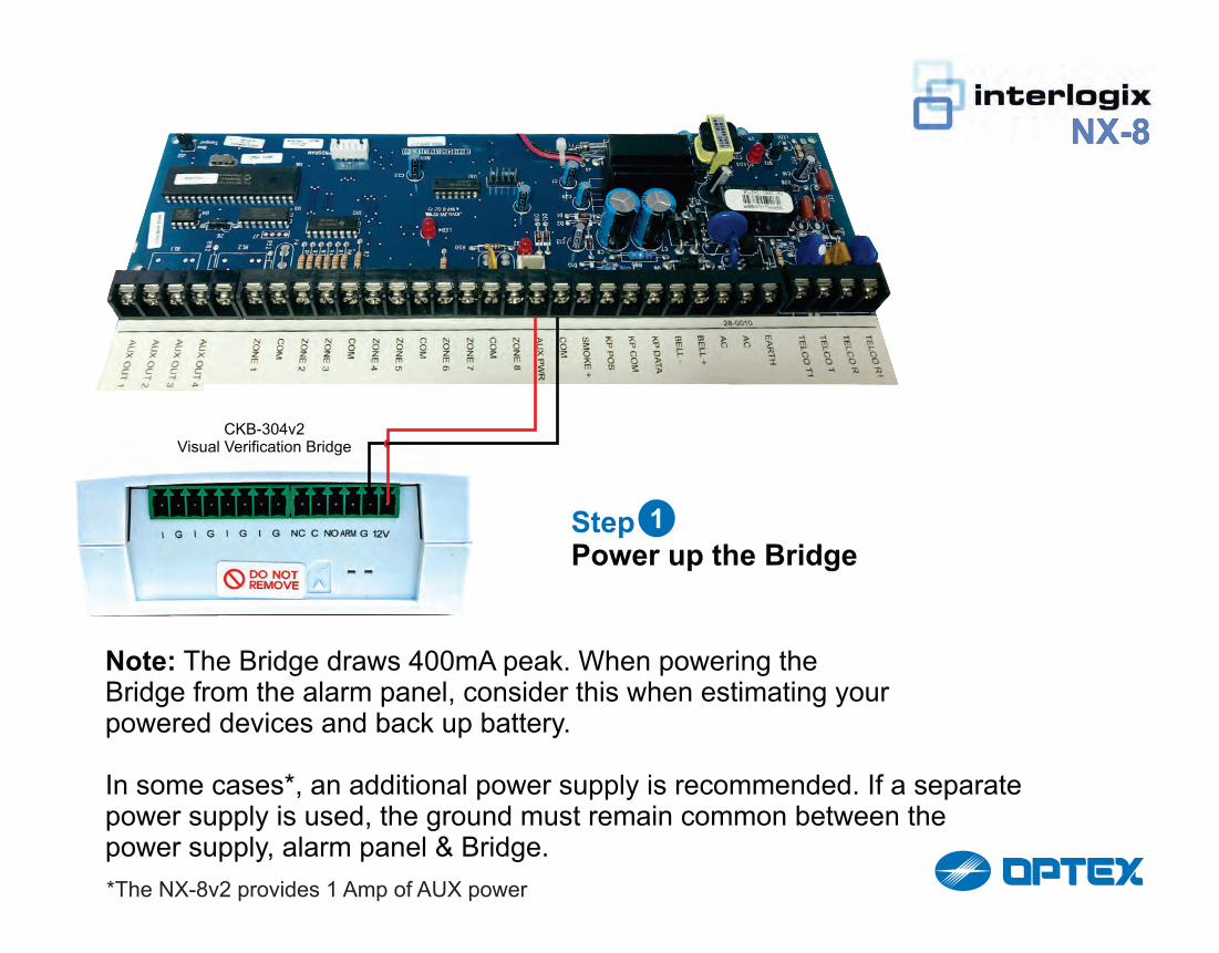
Step 1 Power up the Bridge
1
Note: The Bridge draws 400mA peak. When powering the Bridge from the alarm panel, consider this when estimating your powered devices and back up battery.
In some cases*, an additional power supply is recommended. If a separate power supply is used, the ground must remain common between the power supply, alarm panel & Bridge.
CKB-304v2Visual Verification Bridge
*The NX-8v2 provides 1 Amp of AUX power
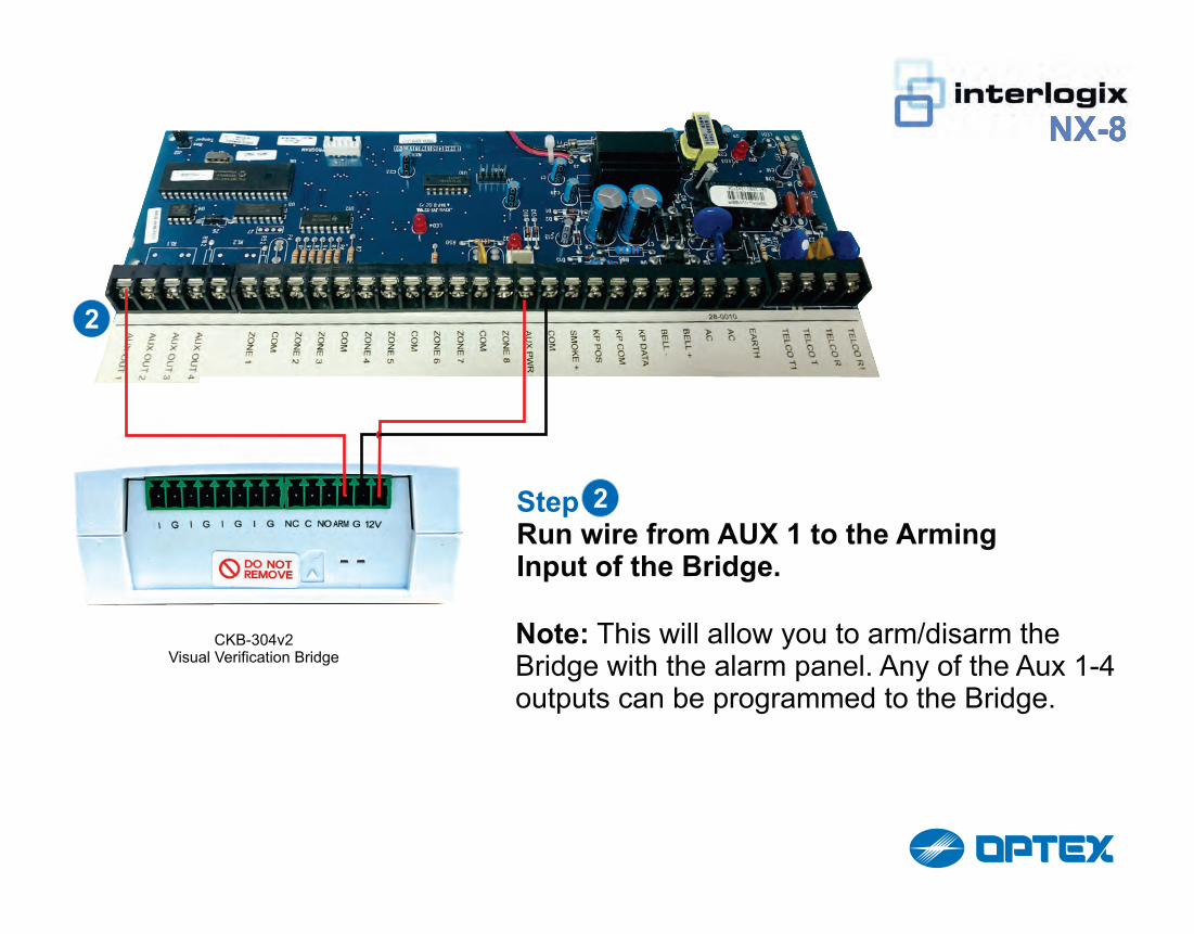
Step 2 Run wire from AUX 1 to the Arming Input of the Bridge.
Note: This will allow you to arm/disarm the Bridge with the alarm panel. Any of the Aux 1-4 outputs can be programmed to the Bridge.
2
NX-8NX-8
CKB-304v2Visual Verification Bridge
2

EXAMPLE
This is a typical burg zone with the EOL at the device.
NX-8NX-8
CKB-304v2Visual Verification Bridge

STEP 4
Run wire from the Bridge inputto the zone terminal of the panel.
3
NX-8
CKB-304v2Visual Verification Bridge
This wiring method requires the Bridge to share a common ground with the alarm panel. Otherwise, the Zone Ground must be wired to the Bridge Input Ground.

ALARM PANEL PROGRAMMING: Aux1 To Arm/Disarm In this scenario, program the following:(assuming no outputs previously used, substitute correct segment if not using output 1)
Location 45 Segment [1]Turn on correct PartitionLocation 46 Segment [1]Ensure 6 is not onLocation [47]Segment 1: 21Segment 2: 0
**On NX8 v2 panels the 4 AUXoutputs are on the screw terminalblock.
CHeKT DEALER PORTAL: Bridge ProgrammingWe recommend using “Loss Of VoltageArming” when possible. This defaults to the bridge being in anarmed state if the wiring for the Arming Pin gets compromised or disconnected for any reason.
NX-8