Civil Pp06
29
Seventh Edition By David A. Madsen, Terence M. Shumaker, and David P. Madsen Civil Drafting Technology Chapter 6 Surveying Fundamentals
description
Civil Drafting Technology
Transcript of Civil Pp06

Seventh EditionBy David A. Madsen,
Terence M. Shumaker, and David P. Madsen
Civil Drafting Technology
Chapter 6Surveying Fundamentals

Civil Drafting Technology, Seventh EditionDavid A. Madsen, Terence M. Shumaker, David P. Madsen
© 2010 Pearson Higher Education,Upper Saddle River, NJ 07458. • All Rights Reserved.2
Figure 6–1: The diameter of the earth measured through the poles is approximately 27 miles less than the diameter measured at the equator.
Civil Drafting Technology, Seventh EditionDavid A. Madsen, Terence M. Shumaker, David P. Madsen
© 2010 Pearson Higher Education,Upper Saddle River, NJ 07458. • All Rights Reserved.3
Figure 6–2: The lengths of a 36-mile arc and a chord connecting the arc’s ends vary by only 0.66 ft.
Civil Drafting Technology, Seventh EditionDavid A. Madsen, Terence M. Shumaker, David P. Madsen
© 2010 Pearson Higher Education,Upper Saddle River, NJ 07458. • All Rights Reserved.4
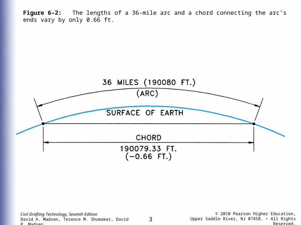
Figure 6–3: A horizontal plane is only 0.66 ft above the earth’s surface at the end of a 1-mile arc.

Civil Drafting Technology, Seventh EditionDavid A. Madsen, Terence M. Shumaker, David P. Madsen
© 2010 Pearson Higher Education,Upper Saddle River, NJ 07458. • All Rights Reserved.5
Figure 6–4: Typical land survey of a subdivision. (Courtesy of Otak, Inc.)
Civil Drafting Technology, Seventh EditionDavid A. Madsen, Terence M. Shumaker, David P. Madsen
© 2010 Pearson Higher Education,Upper Saddle River, NJ 07458. • All Rights Reserved.6
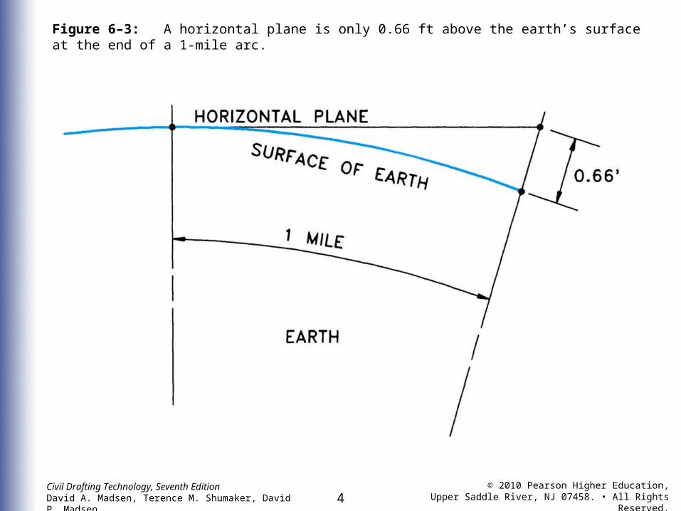
Figure 6–5: A topographic survey is used to compile the information needed to create this topographic map. (Reproduced by permission of the U.S. Geological Survey)

Civil Drafting Technology, Seventh EditionDavid A. Madsen, Terence M. Shumaker, David P. Madsen
© 2010 Pearson Higher Education,Upper Saddle River, NJ 07458. • All Rights Reserved.7
Figure 6–6: A geodetic survey defines major control points that can be used for smaller surveys. (Courtesy of National Geodetic Survey)
Civil Drafting Technology, Seventh EditionDavid A. Madsen, Terence M. Shumaker, David P. Madsen
© 2010 Pearson Higher Education,Upper Saddle River, NJ 07458. • All Rights Reserved.8
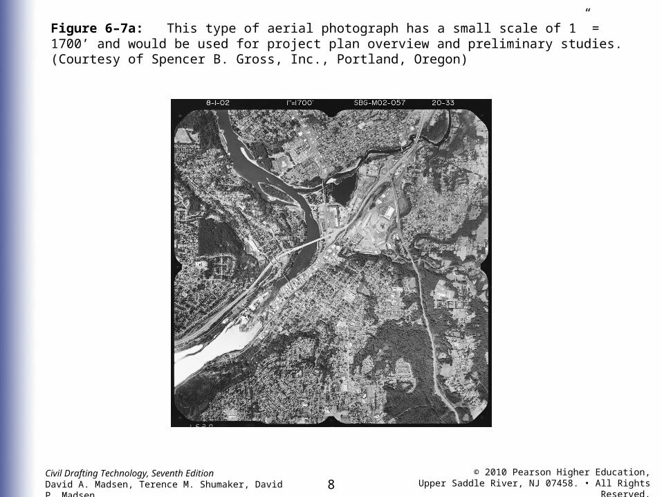
Figure 6–7a: This type of aerial photograph has a small scale of 1” = 1700’ and would be used for project plan overview and preliminary studies. (Courtesy of Spencer B. Gross, Inc., Portland, Oregon)

Civil Drafting Technology, Seventh EditionDavid A. Madsen, Terence M. Shumaker, David P. Madsen
© 2010 Pearson Higher Education,Upper Saddle River, NJ 07458. • All Rights Reserved.9
Figure 6–7b: This photo has a larger scale of 1” = 850’ and would be used for preliminary studies, map design, and GIS applications. (Courtesy of Spencer B. Gross, Inc., Portland, Oregon)

Civil Drafting Technology, Seventh EditionDavid A. Madsen, Terence M. Shumaker, David P. Madsen
© 2010 Pearson Higher Education,Upper Saddle River, NJ 07458. • All Rights Reserved.10
Figure 6–7c: This type of 1” = 170’ large-scale photo would be used for engineering and design work. (Courtesy of Spencer B. Gross, Inc., Portland, Oregon)

Civil Drafting Technology, Seventh EditionDavid A. Madsen, Terence M. Shumaker, David P. Madsen
© 2010 Pearson Higher Education,Upper Saddle River, NJ 07458. • All Rights Reserved.11
Figure 6–8: Specialized 3D stereoscopic mapping workstations and eyewear enable the CAD operator to work in a 3D environment.

Civil Drafting Technology, Seventh EditionDavid A. Madsen, Terence M. Shumaker, David P. Madsen
© 2010 Pearson Higher Education,Upper Saddle River, NJ 07458. • All Rights Reserved.12
Figure 6–9: A stereoscope is used to analyze stereo photos.

Civil Drafting Technology, Seventh EditionDavid A. Madsen, Terence M. Shumaker, David P. Madsen
© 2010 Pearson Higher Education,Upper Saddle River, NJ 07458. • All Rights Reserved.13
Figure 6–10: A route survey or an open traverse does not close on itself.

Civil Drafting Technology, Seventh EditionDavid A. Madsen, Terence M. Shumaker, David P. Madsen
© 2010 Pearson Higher Education,Upper Saddle River, NJ 07458. • All Rights Reserved.14
Figure 6–11: Construction survey showing locations of corners and staking out of house with angles and distances.
Civil Drafting Technology, Seventh EditionDavid A. Madsen, Terence M. Shumaker, David P. Madsen
© 2010 Pearson Higher Education,Upper Saddle River, NJ 07458. • All Rights Reserved.15
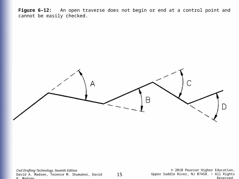
Figure 6–12: An open traverse does not begin or end at a control point and cannot be easily checked.

Civil Drafting Technology, Seventh EditionDavid A. Madsen, Terence M. Shumaker, David P. Madsen
© 2010 Pearson Higher Education,Upper Saddle River, NJ 07458. • All Rights Reserved.16
Figure 6–13: A connecting traverse is one in which the beginning and end points are known.

Civil Drafting Technology, Seventh EditionDavid A. Madsen, Terence M. Shumaker, David P. Madsen
© 2010 Pearson Higher Education,Upper Saddle River, NJ 07458. • All Rights Reserved.17
Figure 6–14: A loop traverse closes on itself and can be checked easily.

Civil Drafting Technology, Seventh EditionDavid A. Madsen, Terence M. Shumaker, David P. Madsen
© 2010 Pearson Higher Education,Upper Saddle River, NJ 07458. • All Rights Reserved.18
Figure 6–15a: The robotic total station combines vertical and horizontal angle measurements with an EDM. (Courtesy of Trimble Navigation)
Civil Drafting Technology, Seventh EditionDavid A. Madsen, Terence M. Shumaker, David P. Madsen
© 2010 Pearson Higher Education,Upper Saddle River, NJ 07458. • All Rights Reserved.19
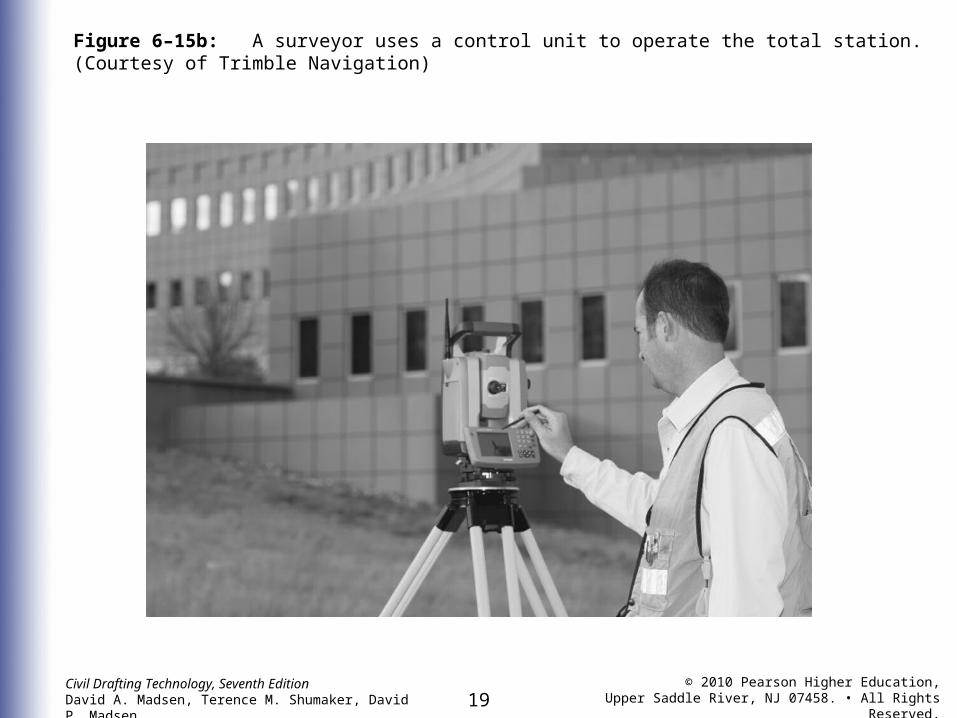
Figure 6–15b: A surveyor uses a control unit to operate the total station. (Courtesy of Trimble Navigation)
Civil Drafting Technology, Seventh EditionDavid A. Madsen, Terence M. Shumaker, David P. Madsen
© 2010 Pearson Higher Education,Upper Saddle River, NJ 07458. • All Rights Reserved.20
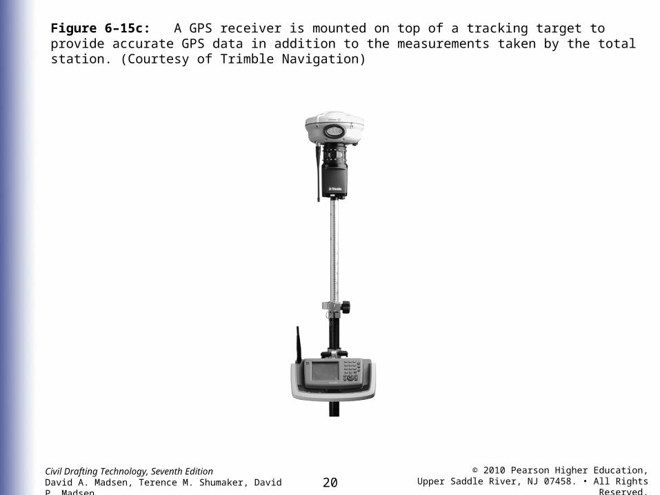
Figure 6–15c: A GPS receiver is mounted on top of a tracking target to provide accurate GPS data in addition to the measurements taken by the total station. (Courtesy of Trimble Navigation)

Civil Drafting Technology, Seventh EditionDavid A. Madsen, Terence M. Shumaker, David P. Madsen
© 2010 Pearson Higher Education,Upper Saddle River, NJ 07458. • All Rights Reserved.21
Figure 6–15d: Data recorded in an electronic total station can be saved in an electronic data collector. (Courtersy of lopcon Positioning Systems, Inc.)

Civil Drafting Technology, Seventh EditionDavid A. Madsen, Terence M. Shumaker, David P. Madsen
© 2010 Pearson Higher Education,Upper Saddle River, NJ 07458. • All Rights Reserved.22
Figure 6–16: Deflection-angle traverse.

Civil Drafting Technology, Seventh EditionDavid A. Madsen, Terence M. Shumaker, David P. Madsen
© 2010 Pearson Higher Education,Upper Saddle River, NJ 07458. • All Rights Reserved.23
Figure 6–17: The foresight is measured by turning the instrument clockwise from the backsight in an angles-tothe- right survey.

Civil Drafting Technology, Seventh EditionDavid A. Madsen, Terence M. Shumaker, David P. Madsen
© 2010 Pearson Higher Education,Upper Saddle River, NJ 07458. • All Rights Reserved.24
Figure 6–18: An azimuth traverse measures each angle clockwise from north or south.

Civil Drafting Technology, Seventh EditionDavid A. Madsen, Terence M. Shumaker, David P. Madsen
© 2010 Pearson Higher Education,Upper Saddle River, NJ 07458. • All Rights Reserved.25
Figure 6–19: A topographic map showing State Plane coordinates and UTM rectangular coordinates. (Reproduced by permission of the U.S. Geological Survey)

Civil Drafting Technology, Seventh EditionDavid A. Madsen, Terence M. Shumaker, David P. Madsen
© 2010 Pearson Higher Education,Upper Saddle River, NJ 07458. • All Rights Reserved.26
Figure 6–20: This surveyor is using a GNSS receiver and a handheld controller to record and annotate global positioning system data. (Courtesy of Trimble Navigation)

Civil Drafting Technology, Seventh EditionDavid A. Madsen, Terence M. Shumaker, David P. Madsen
© 2010 Pearson Higher Education,Upper Saddle River, NJ 07458. • All Rights Reserved.27
Figure 6–21: An example of a raw data file displayed in the Carlson Survey Edit/Process program. (Courtesy Carlson Software)

Civil Drafting Technology, Seventh EditionDavid A. Madsen, Terence M. Shumaker, David P. Madsen
© 2010 Pearson Higher Education,Upper Saddle River, NJ 07458. • All Rights Reserved.28
Figure 6–22: Surveyors can collect at least five pieces of data for a single point and store this as a text point file in the total station data collector. The text file is then used to generate a digital terrain model.
Civil Drafting Technology, Seventh EditionDavid A. Madsen, Terence M. Shumaker, David P. Madsen
© 2010 Pearson Higher Education,Upper Saddle River, NJ 07458. • All Rights Reserved.29
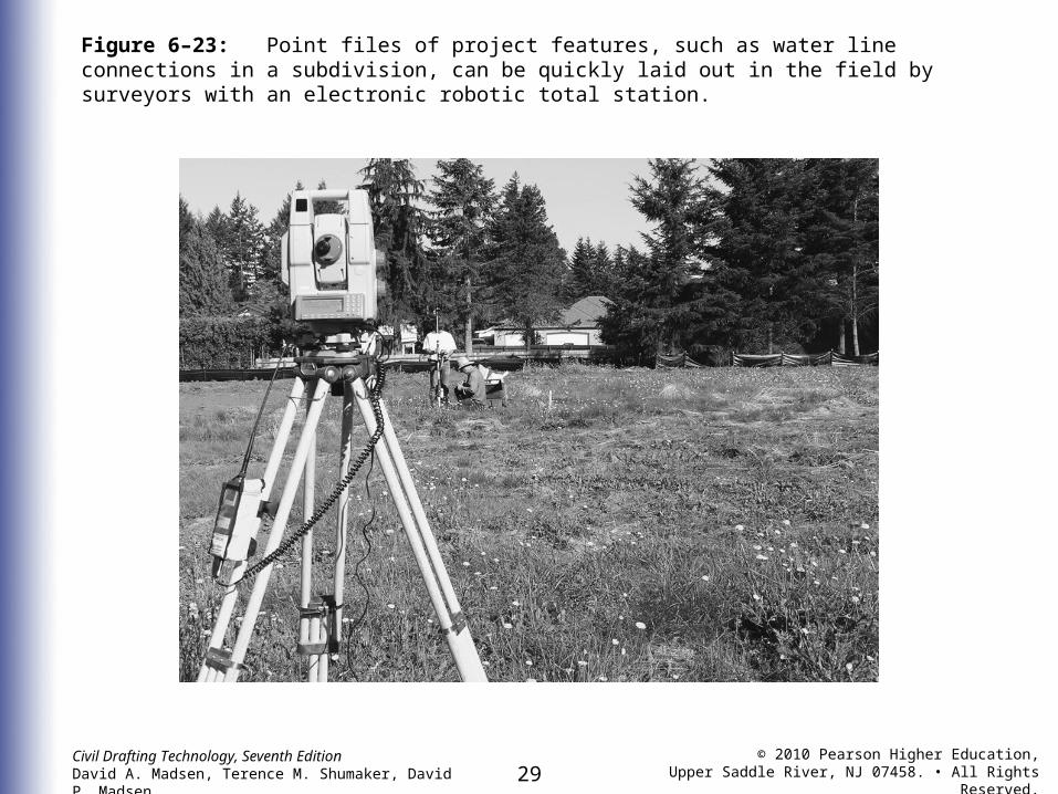
Figure 6–23: Point files of project features, such as water line connections in a subdivision, can be quickly laid out in the field by surveyors with an electronic robotic total station.


![14/05/2020 AUCTION 2 General Auction - *= 20% VAT on the … · PEPPA PIG PP06 FLIP AND LEARN PHONE ELECTRONIC TOY [2726] 7165.*NATURAL HISTORY MUSEUM N5130 DINOSAUR TORCH AND PROJECTOR](https://static.fdocuments.us/doc/165x107/5f891aea8ee8e734e127a4e0/14052020-auction-2-general-auction-20-vat-on-the-peppa-pig-pp06-flip-and.jpg)