Civil Engineering - geoscience.msc.sa.edu.au
26
Student: ………………………… Date received: ……………… Handout 12 of 14 (Topic 5.1) Civil Engineering The Adelaide to Crafers Highway Project, completed in 1999, was one of the most expensive civil engineering projects in the State’s history (Photo: Bernd Michaelsen).
Transcript of Civil Engineering - geoscience.msc.sa.edu.au

Student: ………………………… Date received: ………………
Handout 12 of 14
(Topic 5.1)
Civil Engineering
The Adelaide to Crafers Highway Project, completed in 1999, was one of the most expensive civil engineering projects in the State’s history (Photo: Bernd Michaelsen).

The Impact of Human Activities on the Earth Civil Engineering
Key Ideas Intended Student Learning The surface of the Earth has been considerably altered to meet the perceived needs of technological societies.
Discuss the range of deliberate alterations that human beings have made to the surface of the Earth.
Describe local examples of these changes. The construction of large civil engineering projects requires a knowledge of the geology of the area concerned.
Explain how the geology of an area dictates the location and nature of each of the following structures:
Dams Building foundations. Roads and railways
Describe causes of slope failure and preventive measures that can be taken.
Discuss the role of a geologist in the feasibility study and site selection stages of a large civil engineering project.
Topic 5.1 Civil Engineering Page 2 of 26

5.1 – Civil Engineering INTRODUCTION
Earth's surface has been considerably altered to meet the perceived needs of technological societies. The deliberate alterations which humans have made to Earth’s surface have generally involved extraction of materials or construction of facilities for human use. Examples of facilities that require considerable alteration of Earth’s surface are highways, railways, bridges, dams and pipelines.
The branch of engineering that deals with the planning, construction and maintenance of these major structures is known as CIVIL ENGINEERING. This unit summarises some geological aspects of civil engineering.
An example of a large-scale and recent civil engineering project in the Adelaide region is the Adelaide to Crafers Highway Project, completed in December 1999.
During construction of this project, 10.4 km of the existing Mt Barker Road were replaced by 8.3 km of divided road, comprising two three-lane tunnels. Since the completion of the project, travelling times and fuel costs have been reduced, and safety improved for the many Hills residents who commute to Adelaide each day. The project cost $138 million and its construction employed about 1500 people. GEOLOGICAL CONSTRAINTS
The geology of an area dictates the location and nature of any civil engineering structures.
Roads and Railways
Problems for a road or railway project may be caused by any of the following geological features:
• faults • junctions between hard and soft formations
Topic 5.1 Civil Engineering Page 3 of 26

• boundaries between porous and impermeable formations • spring-lines • fractured granites • weathered schists • landslip areas • areas where beds dip towards the road or
railway, as shown in the adjacent diagram. If the terrain and proposed route are such that these features cannot be avoided, construction of suitable safety features is required. Earthwork construction must include an embankment to stabilise areas of landslip. Lightweight material on a concrete raft may be needed where the road traverses deep, compressible deposits. Drainage holes can be drilled into rock to ensure that water is drained from potential slip surfaces, such as bedding planes. Unless water is properly drained from a rock embankment, pressures will build-up within and behind the rock, eventually causing it to fracture and collapse. The Thredbo Village land-slide (1997) is an Australian example of a catastrophic geological slope failure due to the build-up of water within rocks and soil. The Adelaide to Crafers Highway Project
Because the terrain in the vicinity of the Adelaide-Crafers tunnels is so steep, the project encountered many civil engineering challenges. Notably, the steepness of the terrain increases the probability that rock-falls and landslides will occur.
The Crafers Highway is located on the western margin of the Mt Lofty Ranges, The ranges themselves were formed by movement along fault lines. The highway crosses three major faults, and there are many smaller faults in the area. These faults can and do have a major impact on road-cutting stability.
Many of the rocks are siltstones or mudstones — often described generically as ‘slates’ — which show slaty cleavage. The area is geologically complex, consisting of ‘slates’ and quartzite with variable strengths ranging from low to very high. The amount of weathering of the rock also varies considerably. Some sections are very weathered, while in others the rock is fresh and unaltered. Sometimes joints are closely spaced, whereas in some areas others there are very few.
Topic 5.1 Civil Engineering Page 4 of 26

Consequently, some of the road cuttings have been reinforced to prevent rock-falls. Various treatments can be seen as you drive along the highway. In some places wire mesh has been used, while other faces have been sprayed with concrete — a treatment known as ‘shotcrete’. Similarly different support types were used in the tunnel when different rock types were being tunnelled. When the tunnel excavation was completed, a permanent concrete lining was installed.
Photographs of Crafers Highway road-cutting. Left: Wire mesh prevents loose locks from dislodging from high on the cliff and falling onto the highway. Right: Partial shotcrete treatment of road-cutting. Dams
Geological investigations of a site proposed for construction of a dam must be complete and detailed. Features such as rock-types, geological structures, weathering, fractures and fissures must all be considered. The main considerations are that the material on which the dam rests must be able to carry the weight of the structure without failing. The geology upon which the dam is built must also be impervious to water. The abutments, (the rock faces to which the dam wall is attached) must also be impervious and strong enough to support the dam wall, especially in the case of an arch dam (where more force is transmitted to the abutments).
Left: Cross-section through an arch dam. Failure of a dam can be due to many factors including:
• earthquakes • a sudden drop in water level • inadequate protection of the reservoir side of the dam from wave action • insufficient spillway capacity, so that water flows over the whole of the
dam surface, with consequent erosion
Topic 5.1 Civil Engineering Page 5 of 26
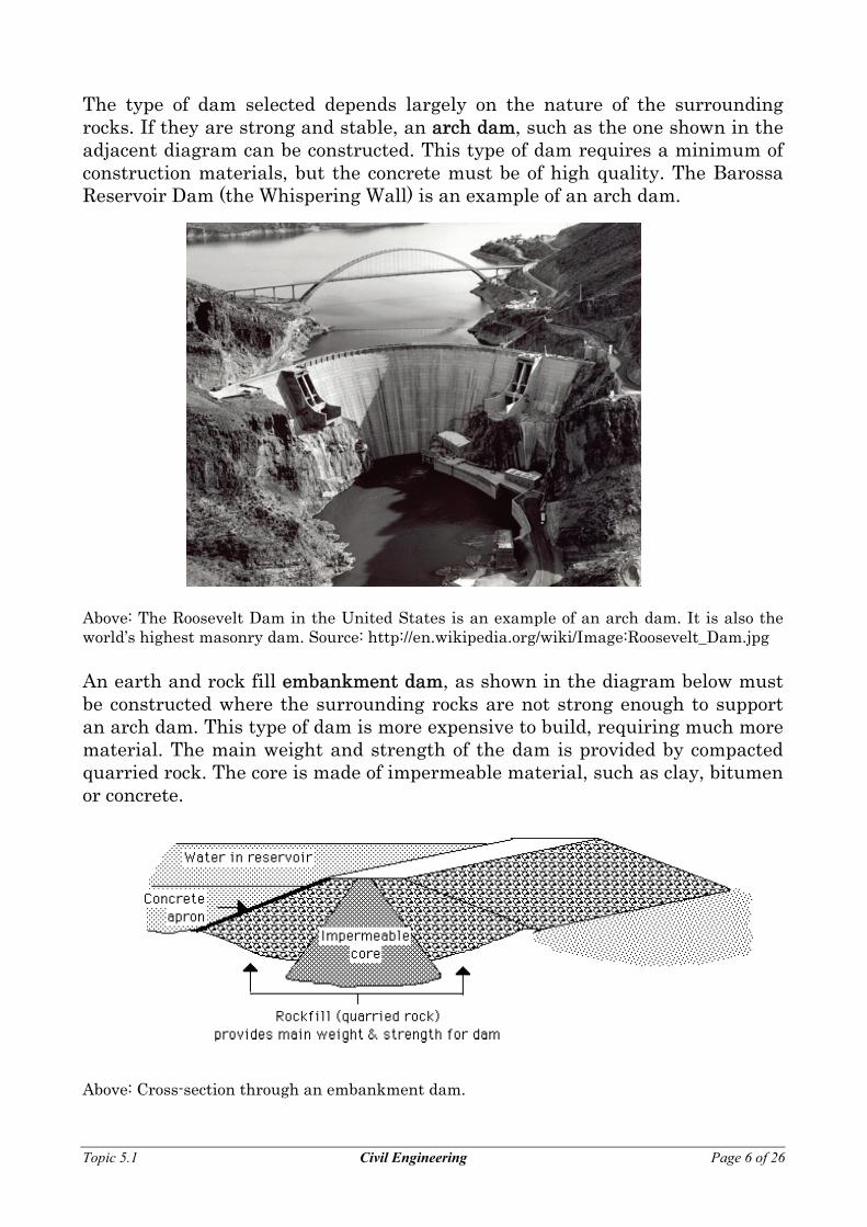
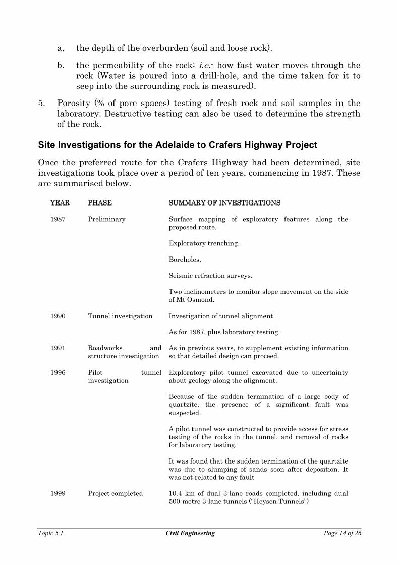
The type of dam selected depends largely on the nature of the surrounding rocks. If they are strong and stable, an arch dam, such as the one shown in the adjacent diagram can be constructed. This type of dam requires a minimum of construction materials, but the concrete must be of high quality. The Barossa Reservoir Dam (the Whispering Wall) is an example of an arch dam. Above: The Roosevelt Dam in the United States is an example of an arch dam. It is also the world’s highest masonry dam. Source: http://en.wikipedia.org/wiki/Image:Roosevelt_Dam.jpg An earth and rock fill embankment dam, as shown in the diagram below must be constructed where the surrounding rocks are not strong enough to support an arch dam. This type of dam is more expensive to build, requiring much more material. The main weight and strength of the dam is provided by compacted quarried rock. The core is made of impermeable material, such as clay, bitumen or concrete. Above: Cross-section through an embankment dam.
Topic 5.1 Civil Engineering Page 6 of 26

Above: The Scrivener Dam (an embankment dam) in Canberra which holds back the waters of Lake Burley Griffin (http://en.wikipedia.org/wiki/Lake_Burley_Griffin). It has been designed to withstand a one in 5000 year flood. Kangaroo Creek Dam
Construction of the Kangaroo Creek Dam was first proposed around 1945. Tests of the surrounding rocks, mainly schists and gneisses, were carried out and it was concluded that they would be strong enough to support an arch dam. However, the project was shelved. During the 1950s, an arch dam was constructed in Europe in an area where the geology was similar to the Torrens Gorge. The geologists did not realise that there was a fault at right angles to the foliation planes of the schist. This dam collapsed in 1958, and several hundred lives were lost.
When construction of the Kangaroo Creek Dam was again proposed in the 1960s, a careful assessment of the surrounding rocks was made. The investigation took about 18 months. Eventually it was decided that the foundation rocks on the south bank of the proposed site were unstable to a considerable depth, and not strong enough to support an arch dam.
A much larger and more expensive earth and rock fill embankment dam was subsequently built.
Topic 5.1 Civil Engineering Page 7 of 26

Building Foundations
Since the type of rock and soil inevitably affects stability of buildings, the quality of the foundation rock must be investigated before construction commences. This rock must not be weak, crushed, water saturated or have been subjected to chemical weathering. The presence of fractures, faults, joints, cleavages, etc may indicate that the site is unsuitable for building. The possibility of soil-creep, slope movement, landslides etc must be borne in mind and factored into the design of any building foundation. Obviously, buildings should not be situated too close to the coast, especially where the sea level is rising relative to the land.
Left: The Leaning Tower of Pisa, Italy. This is possibly the most famous example of “failed foundations” (http://en.wikipedia.org /wiki/To wer_of_Pisa). Rock and soil tests are taken before homes are built. For larger buildings, deep holes may be drilled to test the strength and stability of the rocks under the proposed building. The type and strength of foundations required are determined from the results of these tests. People who build houses in areas of clay soil are likely to find that windows and doors stick and that cracks appear in brick walls. Piers under the house move and concrete slabs may crack. This is because clays swell when wet and shrink after drying. Adelaide’s ‘Bay of Biscay’
soils, which underlie some of the north-eastern suburbs, contain a type of clay called montmorillonite which swells to almost twice its dry volume when wet. This is responsible for many cracks in older buildings. These soils are said to be expansive.
Two other types of problem soils are collapsing soils, which settle rapidly on wetting, and compressible soils that consolidate and settle slowly over several years.
The footing is that part of a house that is in direct contact with the soil or rock forming the foundation. Strip footings were the earliest type used. These consisted of concrete strips beneath the walls of the house.
Topic 5.1 Civil Engineering Page 8 of 26

Strip footings proved to be unsuitable in areas of expansive soil, as the soil under the house dried out and shrank, causing the problems shown in the diagram below. Above: Cross-section through strip footings A range of footings has now been developed, designed to be rigid enough to resist much of the long-term expansive soil movement and to minimise the moisture changes that could occur beneath a house. An example is the grillage raft shown in the adjacent diagram. An alternative approach is to build articulated houses, in which the walls are built in separate sections. Each section is free to move with respect to the other sections. One advantage offered by multi-story buildings is that their foundation loads are generally great enough to resist uplift caused by swelling of expansive soils.
Topic 5.1 Civil Engineering Page 9 of 26

In the 1960s, the footings of high-rise office buildings in the CBD area were carried down to the Hallett Cove Sandstone that underlies much of the Adelaide Plains. However, during excavations for some of these buildings, the sandstone was found to contain caves and sinkholes. More recent buildings use concrete raft foundations that rest on the top stratum — the Hindmarsh Clay. The diagram below contrasts the two different techniques. SLOPE FAILURE
The term slope failure covers a wide range of ground movement, such as rock falls, deep failure of slopes, and shallow debris flows. The photograph below shows the Thredbo landslide (30 July 1997) where 18 people died.
http://www.schools.ash.org.au/elanorah/auThred.jpg Causes of Slope Failure
Gravity
Although gravity acting on an over-steepened slope is the primary cause of a landslide, other contributing factors include:
• earthquakes that create stresses causing weak slopes to fail. • volcanic eruptions that produce loose ash deposits and debris flows. • vibrations from machinery, traffic, blasting, and even atmospheric
thunder that may trigger failure of very weak slopes. • excess weight from accumulation of rain, snow, the stockpiling of rock or
ore, or from built structures that may stress weak slopes to failure.
Topic 5.1 Civil Engineering Page 10 of 26

Relief
Slope failure occurs in hilly or mountainous regions all over the world — essentially wherever there is any significant topographic relief. In Australia, significant landslides coincides with mountainous areas.
Left: Location of significant Australian landslides (http://www.ga.gov.au/image _cache/GA2773.jpg) Water
Rock and soil slopes are weakened through saturation by melting snow or heavy rain. Water filling the pores of permeable materials allows the grains to slide past each other with little friction. Water acts as a lubricant increasing the ease of movement of rock and soil particles (and therefore slope failure).
Slope material that becomes saturated with water may develop a debris flow or mudflow. The resulting slurry of rock and mud can pick up trees, houses, and cars, causing the blocking of bridges and tributaries and increasing the likelihood of flooding. Undercutting
Undercutting is erosion of material at the foot of a cliff or steep bank — e.g. on the outside of a meander. Ultimately the overhang collapses and the process is repeated. Undercutting caused by rivers, glaciers, or ocean waves creates over-steepened slopes, which are prone to failure. Human activities, such as quarrying and road construction also result in undercutting. Rock Types
In unconsolidated material, that is material not held together by cement or by a strong interlocking crystal structure, landslides start after a significant part of the whole rock mass is saturated with water and therefore lubricated. A single shock or vibration can trigger the down-slope movement of an entire unstable hillside. Any area of very weak or fractured materials resting on a steep slope will be likely to experience landslides. Slope Angle
A pile of sand always assumes the same angle of slope, whether it is a few centimetres high, or a huge sand dune. The angle that the sand makes with the
Topic 5.1 Civil Engineering Page 11 of 26

horizontal is called the angle of repose. It is about 37° for fine sand, and steeper for coarse sand and angular pebbles, as shown in the diagrams below.
Fine sand
Coarse sand
Angular pebbles
If a slope is steepened beyond this natural angle, for example for a road cutting, it then becomes unstable and the slightest vibration may lead to slope failure. The angle of repose is reduced if the sand or unconsolidated rock material becomes water-saturated. Moreover, the angle of repose is significantly reduced underwater. PREVENTION OF SLOPE FAILURE
Although the physical cause of many landslides cannot be removed, geologic investigations, good engineering practices, and effective enforcement of land-use management regulations can reduce landslide hazards. Strategies that can be used to control the mass movement of rock and soil include: • the construction of retaining walls • putting drains through retaining walls so that water is not trapped
behind them • constructing terraces to reduce the angle of slope • using grasses or other plants whose roots anchor the slope • sinking piles through unstable debris down to firm bedrock • inserting bolts (rock bolts) to hold unstable rocks.
Of course, the best solution is not to build, or cut roads, through sites susceptible to slope failure — but that means changing human nature. This may also have significant economic drawbacks.
Topic 5.1 Civil Engineering Page 12 of 26

THE ROLE OF THE GEOLOGIST
The branch of geology that deals with application of geological knowledge to civil engineering projects is known as geological engineering or engineering geology. Engineering geologists are needed wherever an understanding of rock properties and geological structures is required, i.e. road construction, building foundations, dam construction etc.
All structures designed and constructed by civil engineers are located in and supported by naturally occurring rocks and soil. Any structure, no matter how strong its materials or how well it is built, will fail unless the rocks and soil on which it is built are strong and stable. Experience shows that dam disasters have usually been the result of failure of the foundation rocks, rather than of the dam itself.
The local geology of an area is important when planning a major construction. The role of an engineering geologist is to ensure that proper assessment of the geological information is made during the planning and building of a project. He/she must have a good understanding of the work of a civil engineer. Moreover, all engineers (whether geological or civil) must have a knowledge of natural processes and products.
Input from a geologist is most important during the feasibility study and site selection stages of a civil engineering project. He/she must determine whether the rocks and other geological features are suitable for the proposed construction.
A geologist and or geological engineer may use:
1. Regional geological mapping to determine distribution of rock types and location of geological structures such as folds, faults etc. Satellite imagery, aerial photographs and topographical maps may provide useful information about these features.
2. Detailed geological mapping of the site area. Sluicing or excavation may be used to remove the soil cover and expose the underlying rocks.
Some of the significant features in the area may be:
• topographical features — gullies, swamps etc • geological surface features — outcrops, soil types, scree slopes etc • Geological bedrock features — joints, cleavage planes, mineralised
zones.
3. Geophysical methods — e.g. a seismic survey or tests of electrical conductivity of the subsurface geology.
4. Drilling (using diamond drills) to test:
Topic 5.1 Civil Engineering Page 13 of 26
a. the depth of the overburden (soil and loose rock).
b. the permeability of the rock; i.e.- how fast water moves through the rock (Water is poured into a drill-hole, and the time taken for it to seep into the surrounding rock is measured).
5. Porosity (% of pore spaces) testing of fresh rock and soil samples in the laboratory. Destructive testing can also be used to determine the strength of the rock.
Site Investigations for the Adelaide to Crafers Highway Project
Once the preferred route for the Crafers Highway had been determined, site investigations took place over a period of ten years, commencing in 1987. These are summarised below.
YEAR PHASE SUMMARY OF INVESTIGATIONS 1987 Preliminary Surface mapping of exploratory features along the
proposed route.
Exploratory trenching.
Boreholes.
Seismic refraction surveys.
Two inclinometers to monitor slope movement on the side of Mt Osmond.
1990 Tunnel investigation Investigation of tunnel alignment.
As for 1987, plus laboratory testing.
1991 Roadworks and structure investigation
As in previous years, to supplement existing information so that detailed design can proceed.
1996
Pilot tunnel investigation
Exploratory pilot tunnel excavated due to uncertainty about geology along the alignment.
Because of the sudden termination of a large body of quartzite, the presence of a significant fault was suspected.
A pilot tunnel was constructed to provide access for stress testing of the rocks in the tunnel, and removal of rocks for laboratory testing.
It was found that the sudden termination of the quartzite was due to slumping of sands soon after deposition. It was not related to any fault
1999 Project completed 10.4 km of dual 3-lane roads completed, including dual 500-metre 3-lane tunnels (“Heysen Tunnels”)
Topic 5.1 Civil Engineering Page 14 of 26

EXERCISES INTRODUCTION 1. Suggest some reasons why humans have made deliberate large-scale
alterations to Earth’s surface.
2. What is civil engineering?
3. List some types of projects that are the concern of civil engineers.
4. Describe the essential features of the Adelaide to Crafers Highway Project.
5. Why should a geologist be consulted before a large civil engineering project, such as a dam, is designed and constructed?
Topic 5.1 Civil Engineering Page 15 of 26

6. The photograph below shows road construction activities. In order to withstand the constant wear from traffic and weather, roads
must be carefully built with level, durable foundations and surfaces. Here, a large truck slowly lets out its load of gravel onto a new road bed. Gravel acts as part of the foundation and will be groomed and pressed by heavy rollers before the asphalt layer is added.
Describe some of the alterations that have to be made to Earth’s surface in order to carry out the road construction shown above.
GEOLOGICAL CONSTRAINTS Roads and Railways 1. List some of the geological features that may cause problems for a road or
railway project.
Topic 5.1 Civil Engineering Page 16 of 26

2. Describe some of the steps which can be taken to stabilise the edges of a road in mountainous country.
3. a. Explain why drainage holes may be drilled into a rock where a cutting has been made for a road or railway.
b. Draw a diagram to show the location of such holes.
4. The diagram below shows the dip of the bedding in three road cuttings.
In each case, comment on the safety of the cutting. A:
B:
C:
Topic 5.1 Civil Engineering Page 17 of 26

5. Explain why there were bound to be engineering geology problems associated with the Adelaide to Crafers Highway Project.
6. Describe some features of the rocks themselves that caused concern to the engineering geologists?
7. Describe the precautions that must be taken to prevent rock-falls in cuttings and in the tunnel?
Dams 1. What are the two most important requirements when considering a site for
a dam?
2. What features of the surrounding rocks must be considered?
3. a. What are the abutments of a dam?
b. What are the requirements for the abutments?
Topic 5.1 Civil Engineering Page 18 of 26

4. List some of the causes of dam failure.
5. Draw diagrams showing the essential features of an arch dam and an earth and rock fill embankment dam.
Arch Dam Embankment Dam
6. Discuss the advantages and disadvantages of each type of dam.
7. Explain why an embankment dam was selected when Kangaroo Creek
dam was eventually built.
Building Foundations 1. Describe some of the rock types and structures that are unsuitable as
foundation rocks for a building.
Topic 5.1 Civil Engineering Page 19 of 26

2. What events could have led to the situation shown in the above diagram?
3. Describe the properties of expansive soils.
4. Explain why problems arise for those who build houses on highly expansive soils.
5. An expansive soil which underlies much of Adelaide’s north-eastern suburbs is called:
6. What are the footings of a building?
Topic 5.1 Civil Engineering Page 20 of 26

7. Discuss some of the advantages and disadvantages of the strip footings shown in the adjacent diagram.
8. Suggest reasons why the
grillage raft would result in a more stable house with less cracking.
9. Name one advantage of the strip footing over the grillage raft.
10. Explain why multi-story buildings may present fewer problems in areas of expansive soils.
11. Draw diagrams showing two different techniques for construction of the
footings for multi-story buildings in the City of Adelaide.
Topic 5.1 Civil Engineering Page 21 of 26

12. Explain why the concrete raft has been preferred over the piled footings.
SLOPE FAILURE Causes of Slope Failure 1. What is the primary cause of a landslide?
2. List some of the other contributing factors.
3. Explain, with the aid of a diagram, the meaning of the term angle of repose.
4. Explain how the angle of repose depends on the nature of the sediment, including its wetness.
5. What is the disadvantage of steepening a slope beyond its natural angle?
Topic 5.1 Civil Engineering Page 22 of 26
6. Describe the contribution of water to landslides.
7. What is undercutting?
8. What types of material are most prone to landslides?
9. Explain, with the aid of a diagram, how the dip of rock strata can affect the stability of a road cutting.
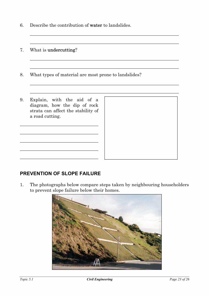
PREVENTION OF SLOPE FAILURE 1. The photographs below compare steps taken by neighbouring householders
to prevent slope failure below their homes.
Topic 5.1 Civil Engineering Page 23 of 26

a. What steps have the owners of the centre block taken to protect their
property?
b. Why do you think their construction has been more effective than the efforts of their neighbours on either side?
2. The photograph below contrasts the effectiveness of different types of vegetation in preventing landslides.
a. Which type of ground cover appears to be more effective?
b. Why do you think this is so?
3. List some other steps that can be taken to control the mass movement of rock and soil.
4. What is the best solution to the problem?
Topic 5.1 Civil Engineering Page 24 of 26

THE ROLE OF THE GEOLOGIST 1. In what situations is an engineering geologist needed?
2. Explain why an engineering geologist is needed in these situations.
3. In what stages of a civil engineering project is a geologist most important?
4. List the steps that might be taken by an engineering geologist to determine whether a site proposed by a group of civil engineers for a large construction (such as a dam) would be suitable for that purpose.
5. The table below summarises the site investigations that were carried out for the Adelaide to Crafers Highway Project. In the right hand column, suggest the purpose of each investigation, bearing in mind the nature of the regional geology.
YEAR PHASE SUMMARY OF INVESTIGATIONS
PURPOSE OF INVESTIGATIONS
1987
Preliminary
Surface mapping along the proposed route. Exploratory trenching and drilling boreholes. Seismic refraction surveys. Two inclinometers to monitor slope
Topic 5.1 Civil Engineering Page 25 of 26

movement on the side of Mt Osmond.
1990
Tunnel investigation
Investigation of tunnel alignment. As for 1987, plus laboratory testing.
YEAR PHASE SUMMARY OF INVESTIGATIONS
PURPOSE OF INVESTIGATIONS
1991
Roadworks and structure investigation
As in previous years.
1996
Pilot tunnel investigation
Exploratory pilot tunnel. excavated.
Topic 5.1 Civil Engineering Page 26 of 26