CIVIL AVIATIION REQUIREMENTS FOR AERODROMES Part 1... · CIVIL AVIATIION REQUIREMENTS FOR...
321
CIVIL AVIATIION REQUIREMENTS FOR AERODROMES CAR-14, Part – I Aerodrome Design and Operations First Edition - 2012 Civil Aviation Authority of Nepal
Transcript of CIVIL AVIATIION REQUIREMENTS FOR AERODROMES Part 1... · CIVIL AVIATIION REQUIREMENTS FOR...
CIVIL AVIATIION
REQUIREMENTS FOR
AERODROMES
CAR-14, Part – I
Aerodrome Design and Operations
First Edition - 2012
Civil Aviation Authority of Nepal

CAR-14
Page ii Civil Aviation Authority of Nepal September 2012
Amendments
Amendments and Corrigenda to these "Civil Aviation requirements for Aerodromes,
Nepal are regularly issued by Director General of CAA, Nepal. The space below is
provided to keep a record of such amendments.
RECORD OF AMENDMENTS AND CORRIGENDA
AMENDMENT CORRIGENDA
No. DATE
APPLICABLE
DATE
ENTERED
ENTERED
BY
No. DATE
APPLICABLE
DATE
ENTERED
ENTERED
BY
1st
Edition
Sept. 2012

CAR-14
Page iii Civil Aviation Authority of Nepal September 2012
TABLE OF CONTENTS
Page
CHAPTER 1.
General............................................................................................................... 1
1.1 Definitions…………………………………………………………………..… 1
1.2 Applicability…………………………………………………………………… 9
1.3 Common reference systems…………………………………………………… 9
1.4 Certification of aerodromes…………………………………………………… 10
1.5 Safety management …………………………………………………………… 10
1.6 Airport design………………………………………………………………….. 10
1.7 Reference code………………………………………………………………… 10
CHAPTER 2.
Aerodrome data……………………………………………………………………. 12
2.1 Aeronautical data……………………………………………………………… 12
2.2 Aerodrome reference point……………………………………………………. 13
2.3 Aerodrome and runway elevations……………………………………………. 13
2.4 Aerodrome reference temperature…………………………………………….. 14
2.5 Aerodrome dimensions and related information……………………………… 14
2.6 Strength of pavements………………………………………………………… 15
2.7 Pre-flight altimeter check location……………………………………………. 17
2.8 Declared distances……………………………………………………………. 18
2.9 Condition of the movement area and related facilities……………………….. 18
2.10 Disabled aircraft removal……………………………………………………. 20
2.11 Rescue and fire fighting……………………………………………………… 20
2.12 Visual approach slope indicator systems……………………………………. 20
2.13 Coordination between aeronautical information
services and aerodrome authorities………………………………………….. 21
CHAPTER 3.
Physical characteristics……………………………………………………………. 23
3.1 Runways……………………………………………………………………….. 23
3.2 Runway shoulders……………………………………………………………… 29
3.3 Runway turn pads……………………………………………………………… 30
3.4 Runway strips………………………………………………………………….. 32
3.5 Runway end safety areas………………………………………………………. 35
3.6 Clearways……………………………………………………………………… 37
3.7 Stopways ………………………………………………………………………. 38
3.8 Radio altimeter operating area…………………………………………………. 39
3.9 Taxiways……………………………………………………………………….. 39
3.10 Taxiway shoulders……………………………………………………………. 46
3.11 Taxiway strips………………………………………………………………… 46
3.12 Holding bays, runway-holding positions intermediate holding positions
And road-holding positions…………………………………………………………47
3.13 Aprons………………………………………………………………………... 49
3.14 Isolated aircraft parking position……………………………………………... 50
3.15 De-Icing/Anti Icing Facilities............................................................................51
CAR-14
Page iv Civil Aviation Authority of Nepal September 2012
CHAPTER 4.
Obstacle restriction and removal………………………………………………..… 53
4.1 Obstacle limitation surfaces…………………………………………………… 53
4.2 Obstacle limitation requirements……………………………………………... 59
4.3 Objects outside the obstacle limitation surfaces………………………………. 65
4.4 Other objects…………………………………………………………………… 65
CHAPTER 5.
Visual aids for navigation…………………………………………………………. 66
5.1 Indicators and signalling devices……………………………………………… 66
5.1.1 Wind direction indicators…………………………………………………… 66
5.1.2 Landing direction indicator…………………………………………………. 66
5.1.3 Signalling lamp……………………………………………………………… 67
5.1.4 Signal panels and signal area……………………………………………….. 67
5.2 Markings……………………………………………………………………… 68
5.2.1 General……………………………………………………………………… 68
5.2.2 Runway designation marking………………………………………………. 69
5.2.3 Runway centre line marking………………………………………………… 70
5.2.4 Threshold marking………………………………………………………….. 71
5.2.5 Aiming point marking ……………………………………………………… 73
5.2.6 Touchdown zone marking…………………………………………………... 75
5.2.7 Runway side stripe marking ………………………………………………… 77
5.2.8 Taxiway centre line marking………………………………………………… 77
5.2.9 Runway turn pad marking…………………………………………………… 80
5.2.10 Runway-holding position marking…………………………………………. 81
5.2.11 Intermediate holding position marking…………………………………….. 82
5.2.12 VOR aerodrome check-point marking …………………………………….. 83
5.2.13 Aircraft stand markings…………………………………………………….. 83
5.2.14 Apron safety lines………………………………………………………….. 85
5.2.15 Road-holding position marking……………………………………………. 85
5.2.16 Mandatory instruction marking …………………………………………… 86
5.2.17 Information marking………………………………………………………. 87
5.3 Lights…………………………………………………………………………. 88
5.3.1 General……………………………………………………………………… 88
5.3.2 Emergency lighting…………………………………………………………. 92
5.3.3 Aeronautical beacons……………………………………………………….. 93
5.3.4 Approach lighting systems …………………………………………………. 94
5.3.5 Visual approach slope indicator systems…………………………………… 103
5.3.6 Circling guidance lights…………………………………………………….. 114
5.3.7 Runway lead-in lighting systems……………………………………………. 115
5.3.8 Runway threshold identification lights……………………………………… 116
5.3.9 Runway edge lights ………………………………………………………… 116
5.3.10 Runway threshold and wing bar lights……………………………………. 117
5.3.11 Runway end lights…………………………………………………………. 120
5.3.12 Runway centre line lights…………………………………………………. 121
5.3.13 Runway touchdown zone lights…………………………………………… 122
5.3.14 Rapid exit taxiway indicator lights………………………………………… 123
5.3.15 Stopway lights……………………………………………………………... 126
5.3.16 Taxiway centre line lights…………………………………………………. 126
5.3.17 Taxiway edge lights……………………………………………………….. 132
5.3.18 Runway turn pad lights……………………………………………………. 133

CAR-14
Page v Civil Aviation Authority of Nepal September 2012
5.3.19 Stop bars…………………………………………………………………… 134
5.3.20 Intermediate holding position lights……………………………………….. 136
5.3.21 De-Icing / Anti Icing Facility Exit Light.....……………………………….. 137
5.3.22 Runway guard lights……………………………………………………….. 137
5.3.23 Apron floodlighting………………………………………………………… 140
5.3.24 Visual docking guidance system…………………………………………… 141
5.3.25 Advanced visual docking guidance system………………………………… 143
5.3.26 Aircraft stand manoeuvring guidance lights……………………………….. 145
5.3.27 Road-holding position light………………………………………………… 146
5.4 Signs……………………………………………………………………………..147
5.4.1 General……………………………………………………………………… 147
5.4.2 Mandatory instruction signs………………………………………………… 151
5.4.3 Information signs…………………………………………………………… 154
5.4.4 VOR aerodrome check-point sign………………………………………….. 157
5.4.5 Aerodrome identification sign……………………………………………… 159
5.4.6 Aircraft stand identification signs………………………………………….. 159
5.4.7 Road-holding position sign…………………………………………………. 159
5.5 Markers……………………………………………………………………….. 160
5.5.1 General……………………………………………………………………… 160
5.5.2 Unpaved runway edge markers…………………………………………….. 160
5.5.3 Stopway edge markers……………………………………………………… 160
5.5.4 Edge markers for snow-covered runways.................................................... 161
5.5.5 Taxiway edge markers……………………………………………………… 161
5.5.6 Taxiway centre line markers……………………………………………….. 162
5.5.7 Unpaved taxiway edge markers…………………………………………….. 162
5.5.8 Boundary markers…………………………………………………………… 163
CHAPTER 6.
Visual aids for denoting obstacles………………………………………………… 164
6.1 Objects to be marked and/or lighted………………………………………….. 164
6.2 Marking of objects ……………………………………………………………. 166
6.3 Lighting of objects ……………………………………………………………. 170
6.4 Wind turbines .................................................................................................. 176
CHAPTER 7.
Visual aids for denoting restricted use areas……………………………………… 177
7.1 Closed runways and taxiways, or parts thereof ……………………………… 177
7.2 Non-load-bearing surfaces……………………………………………………. 177
7.3 Pre-threshold area…………………………………………………………….. 178
7.4 Unserviceable areas…………………………………………………………… 178
CHAPTER 8.
Electrical systems………………………………………………………………… 181
8.1 Electrical power supply systems for air navigation facilities………………… 181
8.2 System design………………………………………………………………… 183
8.3 Monitoring……………………………………………………………………. 183
CHAPTER 9.
Aerodrome operational services, equipment and installations……………………. 185
9.1 Aerodrome emergency planning………………………………………………. 185
9.2 Rescue and fire fighting ………………………………………………………. 187

CAR-14
Page vi Civil Aviation Authority of Nepal September 2012
9.3 Disabled aircraft removal……………………………………………………… 194
9.4 Wildlife strike hazard reduction………………………………………………. 194
9.5 Apron management service……………………………………………………. 195
9.6 Ground servicing of aircraft…………………………………………………… 196
9.7 Aerodrome vehicle operations…………………………………………………. 196
9.8 Surface movement guidance and control systems …………………………… . 197
9.9 Siting of equipment and installations on operational areas…………………… 198
9.10 Fencing……………………………………………………………………….. 200
9.11 Security lighting ……………………………………………………………… 200
CHAPTER 10.
Aerodrome maintenance…………………………………………………………… 201
10.1 General……………………………………………………………………….. 201
10.2 Pavements ……………………………………………………………………. 201
10.3 Runway pavement overlays ………………………………………………….. 203
10.4 Visual aids ……………………………………………………………………. 203
APPENDIX 1.
Colours for aeronautical ground lights,markings, signs and panels………………. 207
1. General………………………………………………………………………….. 207
2. Colours for aeronautical ground lights…………………………………………. 207
3. Colours for markings, signs and panels………………………………………… 209
APPENDIX 2.
Aeronautical ground light characteristics…………………………………………...217
APPENDIX 3.
Mandatory instruction markings and information markings………………………. 243
APPENDIX 4. Requirements concerning design of taxiing guidance signs………. 249
APPENDIX 5.
Aeronautical data quality requirements……………………………………………..261
APPENDIX 6.
Location of lights on obstacles……………………………………………………. 265
APPENDIX 7.
Framework for safety management systems (SMS) …………………………. 273
ATTACHMENT A.
Guidance material supplementary to CAR - 14, Part 1………………………… 276
1. Number, siting and orientation of runways……………………………………… 276
2. Clearways and stopways ……………………………………………………… 277
3. Calculation of declared distances………………………………………………...279
4. Slopes on a runway……………………………………………………………… 280
5. Runway surface evenness ………………………………………………………. 282

CAR-14
Page vii Civil Aviation Authority of Nepal September 2012
6. Determining and expressing the friction characteristics of
Snow and Ice Covered paved Surface .......................................................... 283
7. Determination of friction characteristics of wet paved runways……………….. 286
8. Strips……………………………………………………………………………. 288
9. Runway end safety areas………………………………………………………… 290
10. Location of threshold…………………………………………………………. 290
11. Approach lighting systems…………………………………………………….. 291
12. Priority of installation of visual approach slope indicator systems……………. 299
13. Lighting of unserviceable areas……………………………………………….. 300
14. Rapid exit taxiway indicator lights……………………………………………. 300
15. Intensity control of approach and runway lights ……………………………… 300
16. Signal area …………………………………………………………………...... 301
17. Rescue and fire fighting services………………………………………………. 301
18. Operators of vehicles………………………………………………………...... 304
19. The ACN-PCN method of reporting pavement strength…………………….... 304
ATTACHMENT B.
Obstacle limitation surfaces……………………………………………………….. 306
ATTACHMENT C.
Framework for the State safety programme (SSP)………………………………… 307

CAR-14
Page viii Civil Aviation Authority of Nepal September 2012
ABBREVIATIONS AND SYMBOLS
Abbreviations
ACN - Aircraft classification number
aprx - Approximately
ASDA - Accelerate-stop distance available
ATS - Air traffic services
cd - Candela
C - Degree Celsius
CBR - California bearing ratio
CIE - Commission Internationale de l’Éclairage
cm - Centimetre
DME - Distance measuring equipment
ft - Foot
ILS - Instrument landing system
IMC - Instrument meteorological conditions
K - Degree Kelvin
kg - Kilogram
km - Kilometre
km/h - Kilometre per hour
kt - Knot
L – Litre
LDA - Landing distance available
m – Metre
CAR-14 – Civil Aviation requirements for Aerodromess, Nepal
max – Maximum
mm – Millimetre

CAR-14
Page ix Civil Aviation Authority of Nepal September 2012
mnm - Minimum
MN - Meganewton
MPa - Megapascal
NM - Nautical mile
NU - Not usable
OCA/H - Obstacle clearance altitude/height
OFZ - Obstacle free zone
PCN - Pavement classification number
RESA - Runway end safety area
RVR - Runway visual range
TODA - Take-off distance available
TORA - Take-off run available
VMC - Visual meteorological conditions
VOR - Very high frequency omnidirectional radio range

CAR-14
Page x Civil Aviation Authority of Nepal September 2012
Symbols
° Degree
= Equals
' Minute of arc
µ Friction coefficient
> Greater than
< Less than
% Percentage
± Plus or minus

CAR-14
Page xi Civil Aviation Authority of Nepal September 2012
Amendments to CAR-14, Volume-I
Amendment
Source(s)
Subject(s)
Effective
Date
CAR-14, Part 1, 1st Edition
Annex-14, Fifth Edition-2009
Definitions of instrument runway and obstacle; certification of aerodromes; aerodrome data; enhanced taxiway centre line marking; mandatory instruction marking; taxiway edge lights; advanced visual docking guidance system; mandatory instruction signs; marking and lighting of wind turbines; public health emergencies in aerodrome emergency planning, rescue and fire fighting; wildlife strike hazard reduction; pavement monitoring and maintenance; chromaticity and luminance factors of green colour in Appendix 1; notes to Figures A2-9 and A2-10 for isocandela diagrams for runway edge lights in Appendix 2; NO ENTRY sign in Figure A4-2 in Appendix 4; guidance on runway surface evenness, location of displaced threshold and rescue and fire fighting in Attachment A.
Safety management; Appendix 7, Framework for Safety Management Systems (SMS); Attachment C, Framework for the State Safety Programme (SSP).
Sept. 2012

FOREWORD
Pursuant to Clause -5 Sub-Clause "Pha" and Clause- 35 of Civil Aviation Authority of
Nepal Act, 2053 (1996) and Rule-82, Schedule-3 of Civil Aviation Regulation, 2058
(2002), this "Civil Aviation Requirements for Aerodromes" referred here-in-after as the
"CAR – 14, Part 1" have been enacted by Civil Aviation Authority of Nepal in
accordance with the Standard and Recommended Practices of "Annex -14 Aerodromes,
Volume 1 Aerodrome design and Operations" to the Convention of International Civil
Aviation for safety, regularity or efficiency of International Civil Aviation in Nepal. This
CAR-14, Part 1 is a national standards for design and operation of aerodrome in Nepal.
This "Civil Aviation Requirements for Aerodromes"(CAR-14, Part 1) comes into force
from September, 2012 and supersedes previous "Manual of Aerodrome Standards of
Nepal, Volume 1" 1st Edition 2008.
…………………………. September, 2012 Director General
Civil Aviation Authority of Nepal
Babar Mahal, Kathmandu, Nepal
CAR-14
Page 1 Civil Aviation Authority of Nepal September 2012
CHAPTER- 1
GENERAL
1.1 Definitions
When the following terms are used in this CAR-14, they have the following meanings:
Accuracy. A degree of conformance between the estimated or measured value and the
true value.
Note.— For measured positional data, the accuracy is normally expressed in terms of a
distance from a stated position within which there is a defined confidence of the true
position falling.
Aerodrome. A defined area on land or water (including any buildings, installations and
equipment) intended to be used either wholly or in part for the arrival, departure and
surface movement of aircraft.
Aerodrome beacon. Aeronautical beacon used to indicate the location of an aerodrome
from the air.
Aerodrome certificate. A certificate issued by the appropriate authority under applicable
regulations for the operation of an aerodrome.
Aerodrome elevation. The elevation of the highest point of the landing area.
Aerodrome identification sign. A sign placed on an aerodrome to aid in identifying the
aerodrome from the air.
Aerodrome reference point. The designated geographical location of an aerodrome.
Aerodrome traffic density.
a) Light. Where the number of movements in the mean busy hour is not greater than 15
per runway or typically less than 20 total aerodrome movements.
b) Medium. Where the number of movements in the mean busy hour is of the order of 16
to 25 per runway or typically between 20 to 35 total aerodrome movements.
c) Heavy. Where the number of movements in the mean busy hour is of the order of 26 or
more per runway or typically more than 35 total aerodrome movements.
Note 1.— The number of movements in the mean busy hour is the arithmetic mean over
the year of the number of movements in the daily busiest hour.
Note 2.— Either a take-off or a landing constitutes a movement.
Aeronautical beacon. An aeronautical ground light visible at all azimuths, either
continuously or intermittently, to designate a particular point on the surface of the earth.
Aeronautical ground light. Any light specially provided as an aid to air navigation, other
than a light displayed on an aircraft.
Aeroplane reference field length. The minimum field length required for take-off at
maximum certificated take-off mass, sea level, standard atmospheric conditions, still air
and zero runway slope, as shown in the appropriate aeroplane flight manual prescribed by

CAR-14
Page 2 Civil Aviation Authority of Nepal September 2012
the certificating authority or equivalent data from the aeroplane manufacturer. Field
length means balanced field length for aeroplanes, if applicable, or take-off distance in
other cases.
Note.— Attachment A, Section 2 provides information on the concept of balanced field
length and the Airworthiness Manual (Doc 9760) contains detailed guidance on matters
related to take-off distance.
Aircraft classification number (ACN). A number expressing the relative effect of an
aircraft on a pavement for a specified standard subgrade category.
Note.— The aircraft classification number is calculated with respect to the center of
gravity (CG) position which yields the critical loading on the critical gear. Normally the
aftmost CG position appropriate to the maximum gross apron (ramp) mass is used to
calculate the ACN. In exceptional cases the forwardmost CG position may result in the
nose gear loading being more critical.
Aircraft stand. A designated area on an apron intended to be used for parking an aircraft.
Apron. A defined area, on a land aerodrome, intended to accommodate aircraft for
purposes of loading or unloading passengers, mail or cargo, fuelling, parking or
maintenance.
Apron management service. A service provided to regulate the activities and the
movement of aircraft and vehicles on an apron.
Balked landing. A landing manoeuvre that is unexpectedly discontinued at any point
below the obstacle clearance altitude/height (OCA/H).
Barrette. Three or more aeronautical ground lights closely spaced in a transverse line so
that from a distance they appear as a short bar of light.
Calendar. Discrete temporal reference system that provides the basis for defining
temporal position to a resolution of one day (ISO 19108*).
Capacitor discharge light. A lamp in which high-intensity flashes of extremely short
duration are produced by the discharge of electricity at high voltage through a gas
enclosed in a tube.
Certified aerodrome. An aerodrome whose operator has been granted an aerodrome
certificate.
Clearway. A defined rectangular area on the ground or water under the control of the
appropriate authority, selected or prepared as a suitable area over which an aeroplane may
make a portion of its initial climb to a specified height.
Cyclic redundancy check (CRC). A mathematical algorithm applied to the digital
expression of data that provides a level of assurance against loss or alteration of data.
______________________
* ISO Standard 19108, Geographic Information-Temporal schema

CAR-14
Page 3 Civil Aviation Authority of Nepal September 2012
Data quality. A degree or level of confidence that the data provided meet the
requirements of the data user in terms of accuracy, resolution and integrity.
Datum. Any quantity or set of quantities that may serve as a reference or basis for the
calculation of other quantities (ISO 19104**).
De-icing/anti-icing facility. A facility where frost, ice or snow is removed (de-icing)
from the aeroplane to provide clean surfaces, and/or where clean surfaces of the aeroplane
receive protection (anti-icing) against the formation of frost or ice and accumulation of
snow or slush for a limited period of time.
Note.— Further guidance is given in the Manual of Aircraft Ground De-icing/Anti-icing
Operations (Doc 9640).
De-icing/anti-icing pad. An area comprising an inner area for the parking of an aeroplane
to receive de-icing/anti-icing treatment and an outer area for the manoeuvring of two or
more mobile de-icing/anti-icing equipment.
Declared distances.
a) Take-off run available (TORA). The length of runway declared available and suitable
for the ground run of an aeroplane taking off.
b) Take-off distance available (TODA). The length of the take-off run available plus the
length of the clearway, if provided.
c) Accelerate-stop distance available (ASDA). The length of the take-off run available
plus the length of the stopway, if provided.
d) Landing distance available (LDA). The length of runway which is declared available
and suitable for the ground run of an aeroplane landing.
Dependent parallel approaches. Simultaneous approaches to parallel or near-parallel
instrument runways where radar separation minima between aircraft on adjacent extended
runway centre lines are prescribed.
Displaced threshold. A threshold not located at the extremity of a runway.
Effective intensity. The effective intensity of a flashing light is equal to the intensity of a
fixed light of the same colour which will produce the same visual range under identical
conditions of observation.
Ellipsoid height (Geodetic height). The height related to the reference ellipsoid,
measured along the ellipsoidal outer normal through the point in question.
Fixed light. A light having constant luminous intensity when observed from a fixed point.
Frangible object. An object of low mass designed to break, distort or yield on impact so
as to present the minimum hazard to aircraft.
Note.— Guidance on design for frangibility is contained in the Aerodrome Design
Manual (Doc 9157), Part 6.
________________________
** ISO Standard 19104, Geographic Information-Terminology

CAR-14
Page 4 Civil Aviation Authority of Nepal September 2012
Geodetic datum. A minimum set of parameters required to define location and orientation
of the local reference system with respect to the global reference system/frame.
Geoid. The equipotential surface in the gravity field of the earth which coincides with the
undisturbed mean sea level (MSL) extended continuously through the continents.
Note.— The geoid is irregular in shape because of local gravitational disturbances (wind
tides, salinity, current, etc.) and the direction of gravity is perpendicular to the geoid at
every point.
Geoid undulation. The distance of the geoid above (positive) or below (negative) the
mathematical reference ellipsoid.
Note.— In respect to the World Geodetic System — 1984 (WGS-84) defined ellipsoid, the
difference between the WGS- 84 ellipsoidal height and orthometric height represents
WGS-84 geoid undulation.
Gregorian calendar. Calendar in general use; first introduced in 1582 to define a year
that more closely approximates the tropical year than the Julian calendar (ISO 19108***).
Note.— In the Gregorian calendar, common years have 365 days and leap years 366 days
divided into twelve sequential months.
Hazard beacon. An aeronautical beacon used to designate a danger to air navigation.
Heliport. An aerodrome or a defined area on a structure intended to be used wholly or in
part for the arrival, departure and surface movement of helicopters.
Holding bay. A defined area where aircraft can be held, or bypassed, to facilitate efficient
surface movement of aircraft.
Holdover time. The estimated time the anti-icing fluid (treatment) will prevent the
formation of ice and frost and the accumulation of snow on the protected (treated)
surfaces of an aeroplane.
Human Factors principles. Principles which apply to aeronautical design, certification,
training, operations and maintenance and which seek safe interface between the human
and other system components by proper consideration to human performance.
Human performance. Human capabilities and limitations which have an impact on the
safety and efficiency of aeronautical operations.
Identification beacon. An aeronautical beacon emitting a coded signal by means of
which a particular point of reference can be identified.
Independent parallel approaches. Simultaneous approaches to parallel or near-parallel
instrument runways where radar separation minima between aircraft on adjacent extended
runway centre lines are not prescribed.
Independent parallel departures. Simultaneous departures from parallel or near-parallel
instrument runways.
_______________________
*** ISO Standard 19108, Geographic Information-Temporal schema

CAR-14
Page 5 Civil Aviation Authority of Nepal September 2012
Instrument runway. One of the following types of runways intended for the operation of
aircraft using instrument approach procedures:
a) Non-precision approach runway. An instrument runway served by visual aids and a
non-visual aid providing at least directional guidance adequate for a straight-in approach.
b) Precision approach runway, category I. An instrument runway served by ILS and/or
MLS and visual aids intended for operations with a decision height not lower than 60 m
(200 ft) and either a visibility not less than 800 m or a runway visual range not less than
550 m.
c) Precision approach runway, category II. An instrument runway served by ILS and/or
MLS and visual aids intended for operations with a decision height lower than 60 m (200
ft) but not lower than 30 m (100 ft) and a runway visual range not less than 300m.
d) Precision approach runway, category III. An instrument runway served by ILS and/or
MLS to and along the surface of the runway and:
A — intended for operations with a decision height lower than 30 m (100 ft), or no
decision height and a runway visual range not less than 175m.
B — intended for operations with a decision height lower than 15 m (50 ft), or no
decision height and a runway visual range less than 175m but not less than 50 m.
C — intended for operations with no decision height and no runway visual range
limitations.
Note 1.— See Annex 10, Part 1 for related ILS and/or MLS specifications.
Note 2.— Visual aids need not necessarily be matched to the scale of non-visual aids
provided. The criterion for the selection of visual aids is the conditions in which
operations are intended to be conducted.
Integrity (aeronautical data). A degree of assurance that an aeronautical data and its
value has not been lost nor altered since the data origination or authorized amendment.
Intermediate holding position. A designated position intended for traffic control at which
taxiing aircraft and vehicles shall stop and hold until further cleared to proceed, when so
instructed by the aerodrome control tower.
Landing area. That part of a movement area intended for the landing or take-off of
aircraft.
Landing direction indicator. A device to indicate visually the direction currently
designated for landing and for take-off.
Laser-beam critical flight zone (LCFZ). Airspace in the proximity of an aerodrome but
beyond the LFFZ where the irradiance is restricted to a level unlikely to cause glare
effects.
Laser-beam free flight zone (LFFZ). Airspace in the immediate proximity to the
aerodrome where the irradiance is restricted to a level unlikely to cause any visual
disruption.
Laser-beam sensitive flight zone (LSFZ). Airspace outside, and not necessarily
contiguous with, the LFFZ and LCFZ where the irradiance is restricted to a level unlikely
to cause flash-blindness or after-image effects.

CAR-14
Page 6 Civil Aviation Authority of Nepal September 2012
Lighting system reliability. The probability that the complete installation operates within
the specified tolerances and that the system is operationally usable.
Manoeuvring area. That part of an aerodrome to be used for the take-off, landing and
taxiing of aircraft, excluding aprons.
Marker. An object displayed above ground level in order to indicate an obstacle or
delineate a boundary.
Marking. A symbol or group of symbols displayed on the surface of the movement area
in order to convey aeronautical information.
Movement area. That part of an aerodrome to be used for the take-off, landing and
taxiing of aircraft, consisting of the manoeuvring area and the apron(s).
Near-parallel runways. Non-intersecting runways whose extended centre lines have an
angle of convergence/divergence of 15 degrees or less.
Non-instrument runway. A runway intended for the operation of aircraft using visual
approach procedures.
Normal flight zone (NFZ). Airspace not defined as LFFZ, LCFZ or LSFZ but which
must be protected from laser radiation capable of causing biological damage to the eye.
Obstacle. All fixed (whether temporary or permanent) and mobile objects, or parts
thereof, that:
a) are located on an area intended for the surface movement of aircraft; or
b) extend above a defined surface intended to protect aircraft in flight; or
c) stand outside those defined surfaces and that have been assessed as being a hazard to
air navigation.
Obstacle free zone (OFZ). The airspace above the inner approach surface, inner
transitional surfaces, and balked landing surface and that portion of the strip bounded by
these surfaces, which is not penetrated by any fixed obstacle other than a low-mass and
frangibly mounted one
required for air navigation purposes.
Orthometric height. Height of a point related to the geoid, generally presented as an MSL
elevation.
Pavement classification number (PCN). A number expressing the bearing strength of a
pavement for unrestricted operations.
Precision approach runway, see Instrument runway.
Primary runway(s). Runway(s) used in preference to others whenever conditions permit.
Protected flight zones. Airspace specifically designated to mitigate the hazardous effects
of laser radiation.

CAR-14
Page 7 Civil Aviation Authority of Nepal September 2012
Road. An established surface route on the movement area meant for the exclusive use of
vehicles.
Road-holding position. A designated position at which vehicles may be required to hold.
Runway. A defined rectangular area on a land aerodrome prepared for the landing and
take-off of aircraft.
Runway end safety area (RESA). An area symmetrical about the extended runway centre
line and adjacent to the end of the strip primarily intended to reduce the risk of damage to
an aeroplane undershooting or overrunning the runway.
Runway guard lights. A light system intended to caution pilots or vehicle drivers that
they are about to enter an active runway.
Runway-holding position. A designated position intended to protect a runway, an
obstacle limitation surface, or an ILS/ MLS critical/sensitive area at which taxiing aircraft
and
vehicles shall stop and hold, unless otherwise authorized by the aerodrome control tower.
Note.— In radiotelephony phraseologies, the expression “holding point” is used to
designate the runway-holding position.
Runway strip. A defined area including the runway and stopway, if provided, intended:
a) to reduce the risk of damage to aircraft running off a runway; and
b) to protect aircraft flying over it during take-off or landing operations.
Runway turn pad. A defined area on a land aerodrome adjacent to a runway for the
purpose of completing a 180-degree turn on a runway.
Runway visual range (RVR). The range over which the pilot of an aircraft on the centre
line of a runway can see the runway surface markings or the lights delineating the runway
or identifying its centre line.
Safety programme. An integrated set of regulations and activities aimed at improving
safety.
Safety management system. A systematic approach to managing safety including the
necessary organizational structure, accountabilities, policies and procedures.
Segregated parallel operations. Simultaneous operations on parallel or near-parallel
instrument runways in which one runway is used exclusively for approaches and the other
runway is used exclusively for departures.
Shoulder. An area adjacent to the edge of a pavement so prepared as to provide a
transition between the pavement and the adjacent surface.
Sign.
a) Fixed message sign. A sign presenting only one message.

CAR-14
Page 8 Civil Aviation Authority of Nepal September 2012
b) Variable message sign. A sign capable of presenting several pre-determined messages
or no message, as applicable.
Signal area. An area on an aerodrome used for the display of ground signals.
Slush. Water-saturated snow which with a heel-and-toe slap down motion against the
ground will be displaced with a splatter; specific gravity: 0.5 up to 0.8.
Note.— Combinations of ice, snow and/or standing water may, especially when rain, rain
and snow, or snow is falling, produce substances with specific gravities in excess of 0.8.
These substances, due to their high water/ice content, will have a transparent rather than
a cloudy appearance and, at the higher specific gravities, will be readily distinguishable
from slush.
Snow (on the ground).
a) Dry snow. Snow which can be blown if loose or, if compacted by hand, will fall
apart again upon release; specific gravity: up to but not including 0.35.
b) Wet snow. Snow which, if compacted by hand, will stick together and tend to or
form a snowball; specific gravity: 0.35 up to but not including 0.5.
c) Compacted snow. Snow which has been compressed into a solid mass that resists
further compression and will hold together or break up into lumps if picked up;
specific gravity: 0.5 and over.
Station declination. An alignment variation between the zero degree radial of a VOR and
true north, determined at the time the VOR station is calibrated.
Stopway. A defined rectangular area on the ground at the end of take-off run available
prepared as a suitable area in which an aircraft can be stopped in the case of an
abandoned take off.
Switch-over time (light). The time required for the actual intensity of a light measured in
a given direction to fall from 50 per cent and recover to 50 per cent during a power supply
changeover, when the light is being operated at intensities of 25 per cent or above.
Take-off runway. A runway intended for take-off only.
Taxiway. A defined path on a land aerodrome established for the taxiing of aircraft and
intended to provide a link between one part of the aerodrome and another, including:
a) Aircraft stand taxilane. A portion of an apron designated as a taxiway and
intended to provide access to aircraft stands only.
b) Apron taxiway. A portion of a taxiway system located on an apron and intended to
provide a through taxi route across the apron.
c) Rapid exit taxiway. A taxiway connected to a runway at an acute angle and
designed to allow landing aeroplanes to turn off at higher speeds than are achieved
on other exit taxiways thereby minimizing runway occupancy times.
Taxiway intersection. A junction of two or more taxiways.

CAR-14
Page 9 Civil Aviation Authority of Nepal September 2012
Taxiway strip. An area including a taxiway intended to protect an aircraft operating on
the taxiway and to reduce the risk of damage to an aircraft accidentally running off the
taxiway.
Threshold. The beginning of that portion of the runway usable for landing.
Touchdown zone. The portion of a runway, beyond the threshold, where it is intended
landing aeroplanes first contact the runway.
Usability factor. The percentage of time during which the use of a runway or system of
runways is not restricted because of the cross-wind component.
Note.— Cross-wind component means the surface wind component at right angles to the
runway centre line.
1.2 Applicability
1.2.1 The specifications specified in this CAR-14 shall apply to all civil aerodromes open
to public use in Nepal. The specifications in the chapter 3 shall apply only to land
aerodromes. The specifications in the CAR-14 shall apply, where appropriate, to heliports
but shall not apply to stolports.
1.2.2 Wherever a colour is referred to in this CAR-14, the specifications for that colour
given in Appendix 1 shall apply.
1.3 Common reference systems
1.3.1 Horizontal reference system
World Geodetic System — 1984 (WGS-84) shall be used as the horizontal (geodetic)
reference system. Reported aeronautical geographical coordinates (indicating latitude and
longitude) shall be expressed in terms of the WGS-84 geodetic reference datum.
Note.— Comprehensive guidance material concerning WGS-84 is contained in the World
Geodetic System — 1984 (WGS-84) Manual (Doc 9674).
1.3.2 Vertical reference system
Mean sea level (MSL) datum, which gives the relationship of gravity-related height
(elevation) to a surface known as the geoid, shall be used as the vertical reference system.
Note 1.— The geoid globally most closely approximates MSL. It is defined as the
equipotential surface in the gravity field of the Earth which coincides with the
undisturbed MSL extended continuously through the continents.
Note 2.— Gravity-related heights (elevations) are also referred to as orthometric heights
while distances of points above the ellipsoid are referred to as ellipsoidal heights.
1.3.3 Temporal reference system
1.3.3.1 The Gregorian calendar and Coordinated Universal Time (UTC) shall be used as
the temporal reference system.

CAR-14
Page 10 Civil Aviation Authority of Nepal September 2012
1.4 Certification of aerodromes
1.4.1 The operator of an aerodrome intended for public use shall be in possession of an
aerodrome certificate.
1.4.2 The aerodrome certificate shall be obtained to operate international air
transportation at any airport of Nepal.
1.4.3 As part of the certification process, the aerodrome operators shall prepare and
submit to the Director General of Civil Aviation Authority of Nepal an aerodrome manual
which will include all pertinent information on the aerodrome site, facilities, services,
equipment, operating procedures, organization and management including a safety
management system, is submitted by the applicant for acceptance prior to granting the
aerodrome certificate.
1.5 Safety management
1.5.1 As part of the safety programme established by the Director General of Civil
Aviation Authority of Nepal, each certified aerodrome operator shall implement a safety
management system.
1.6 Airport design
1.6.1 Architectural and infrastructure-related requirements for the optimum
implementation of international civil aviation security measures shall be integrated into
the design and construction of new facilities and alterations to existing facilities at an
aerodrome.
Note.— Guidance on all aspects of the planning of aerodromes including security
considerations is contained in the Airport Planning Manual (Doc 9184), Part 1.
1.6.2 The design of aerodromes shall take into account land-use and environmental
control measures.
Note.— Guidance on land-use planning and environmental control measures is contained
in the Airport Planning Manual (Doc 9184), Part 2.
1.7 Reference code
Introductory Note.— The intent of the reference code is to provide a simple method for
interrelating the numerous specifications concerning the characteristics of aerodromes so
as to provide a series of aerodrome facilities that are suitable for the aeroplanes that are
intended to operate at the aerodrome. The code is not intended to be used for determining
runway length or pavement strength requirements. The code is composed of two elements
which are related to the aeroplane performance characteristics and dimensions. Element
1 is a number based on the aeroplane reference field length and element 2 is a letter
based on the aeroplane wing span and outer main gear wheel span. A particular
specification is
related to the more appropriate of the two elements of the code or to an appropriate
combination of the two code elements. The code letter or number within an element
selected for design purposes is related to the critical aeroplane characteristics for which

CAR-14
Page 11 Civil Aviation Authority of Nepal September 2012
the facility is provided. When applying this CAR-14, the aeroplanes which the aerodrome
is intended to
serve are first identified and then the two elements of the code.
1.7.1 An aerodrome reference code — code number and letter — which is selected for
aerodrome planning purposes shall be determined in accordance with the characteristics
of the aeroplane for which an aerodrome facility is intended.
1.7.2 The aerodrome reference code numbers and letters shall have the meanings assigned
to them in Table 1-1.
1.7.3 The code number for element 1 shall be determined from Table 1-1, column 1,
selecting the code number corresponding to the highest value of the aeroplane reference
field lengths of the aeroplanes for which the runway is intended.
Note.— The determination of the aeroplane reference field length is solely for the
selection of a code number and is not intended to influence the actual runway length
provided.
1.7.4 The code letter for element 2 shall be determined from Table 1-1, column 3, by
selecting the code letter which corresponds to the greatest wing span, or the greatest outer
main gear wheel span, whichever gives the more demanding code letter of the aeroplanes
for which the facility is
intended.
Note.— Guidance to assist the appropriate authority in determining the aerodrome
reference code is given in the Aerodrome Design Manual (Doc 9157), Parts 1 and 2.
Table 1-1. Aerodrome reference code
Note: Annexes, Manuals/Documents etc. are refered to ICAO Annexes, Manuals/Documents
CAR-14
Page 12 Civil Aviation Authority of Nepal September 2012
CHAPTER- 2
AERODROME DATA
2.1 Aeronautical data
2.1.1 Determination and reporting of aerodrome related aeronautical data shall be in
accordance with the accuracy and integrity requirements set forth in Tables 1 to 5 contained
in Appendix 5 while taking into account the established quality system procedures. Accuracy
requirements for aeronautical data are based upon a 95 per cent confidence level and in that
respect, three types of positional data shall be identified:
a. surveyed points (e.g. runway threshold)
b. calculated points (mathematical calculations from the known surveyed points of points in
space, fixes) and
c. declared points (e.g. flight information region boundary points).
Note.— Specifications governing the quality system are given in ICAO Annex 15, Chapter 3.
2.1.2 Aerodrome Operators shall ensure that integrity of aeronautical data is maintained
throughout the data process from survey/origin to the next intended user. Aeronautical data
integrity requirements shall be based upon the potential risk resulting from the corruption of
data and upon the use to which the data item is put. Consequently, the following
classification and data integrity level shall apply:
a) critical data, integrity level 1X10⁻⁸
: there is a high probability when using corrupted critical
data that the continued safe flight and landing of an aircraft would be severely at risk with the
potential for catastrophe;
b) essential data, integrity level 1X10⁻⁵
: there is a low probability when using corrupted
essential data that the continued safe flight and landing of an aircraft would be severely at
risk with the potential for catastrophe; and
c) routine data, integrity level 1X10⁻³
: there is a very low probability when using corrupted
routine data that the continued safe flight and landing of an aircraft would be severely at risk
with the potential for catastrophe.
2.1.3 Protection of electronic aeronautical data while stored or in transit shall be totally
monitored by the cyclic redundancy check (CRC). To achieve protection of the integrity level
of critical and essential aeronautical data as classified in 2.1.2, a 32 or 24 bit CRC algorithm
shall apply respectively.
2.1.4 Recommendation.- To achieve protection of the integrity level of routine aeronautical
data as classified in 2.1.2, a 16 bit CRC algorithm should apply.
Note.— Guidance material on the aeronautical data quality requirements (accuracy,
resolution, integrity, protection and traceability) is contained in the World Geodetic System
— 1984 (WGS-84) Manual (Doc 9674). Supporting material in respect of the provisions of
Appendix 5 related to accuracy and integrity of aeronautical data, is contained in RTCA
Document DO-201A and European Organization for Civil Aviation Equipment (EUROCAE)
Document ED-77, entitled Industry Requirements for Aeronautical Information.

CAR-14
Page 13 Civil Aviation Authority of Nepal September 2012
2.1.5 Geographical coordinates indicating latitude and longitude shall be determined and
reported to the aeronautical information services authority in terms of the World Geodetic
System —1984 (WGS-84) geodetic reference datum, identifying those geographical
coordinates which have been transformed into WGS-84 coordinates by mathematical means
and whose accuracy of original field work does not meet the requirements in Appendix 5,
Table A5-1.
2.1.6 The order of accuracy of the field work shall be such that the resulting operational
navigation data for the phases of flight will be within the maximum deviations, with respect
to an appropriate reference frame, as indicated in tables contained in Appendix 5.
2.1.7 In addition to the elevation (referenced to mean sea level) of the specific surveyed
ground positions at aerodromes, geoid undulation (referenced to the WGS-84 ellipsoid) for
those positions as indicated in Appendix 5, shall be determined and reported to the
aeronautical information services authority.
Note 1.— An appropriate reference frame is that which enables WGS-84 to be realized on
a given aerodrome and with respect to which all coordinate data are related.
Note 2.— Specifications governing the publication of WGS-84 coordinates are given in
Annex 4, Chapter 2 and Annex 15, Chapter 3.
2.2 Aerodrome reference point
2.2.1 An aerodrome reference point shall be established for an aerodrome.
2.2.2 The aerodrome reference point shall be located near the initial or planned geometric
centre of the aerodrome and shall normally remain where first established.
2.2.3 The position of the aerodrome reference point shall be measured and reported to the
aeronautical information services authority in degrees, minutes and seconds.
2.3 Aerodrome and runway elevations
2.3.1 The aerodrome elevation and geoid undulation at the aerodrome elevation position shall
be measured to the accuracy of one-half metre or foot and reported to the aeronautical
information services authority.
2.3.2 For an aerodrome used by international civil aviation for non-precision approaches, the
elevation and geoid undulation of each threshold, the elevation of the runway end and any
significant high and low intermediate points along the runway shall be measured to the
accuracy of one-half metre or foot and reported to the aeronautical information services
authority.
2.3.3 For precision approach runway, the elevation and geoid undulation of the threshold, the
elevation of the runway end and the highest elevation of the touchdown zone shall be
measured to the accuracy of one-quarter metre or foot and reported to the aeronautical
information services authority.
Note.— Geoid undulation must be measured in accordance with the appropriate system of
coordinates.

CAR-14
Page 14 Civil Aviation Authority of Nepal September 2012
2.4 Aerodrome reference temperature
2.4.1 An aerodrome reference temperature shall be determined for an aerodrome in degrees
Celsius.
2.4.2 The aerodrome reference temperature shall be the monthly mean of the daily maximum
temperatures for the hottest month of the year (the hottest month being that which has the
highest monthly mean temperature). This temperature should be averaged over a period of
years.
2.5 Aerodrome dimensions and related information
2.5.1 The following data shall be measured or described, as appropriate, for each facility
provided on an aerodrome:
a) runway — true bearing to one-hundredth of a degree, designation number, length, width,
displaced threshold location to the nearest metre or foot, slope, surface type, type of runway
and, for a precision approach runway category I, the existence of an obstacle free zone when
provided;
b) strip, runway end safety area and stopway - length, width to the nearest metre or foot,
surface type;
c) taxiway — designation, width, surface type;
d) apron — surface type, aircraft stands;
e) the boundaries of the air traffic control service;
f) clearway — length to the nearest metre or foot, ground profile;
g) visual aids for approach procedures, marking and lighting of runways, taxiways and
aprons, other visual guidance and control aids on taxiways and aprons, including taxi-holding
positions and stopbars, and location and type of visual docking guidance systems;
h) location and radio frequency of any VOR aerodrome check-point;
i) location and designation of standard taxi-routes; and
j) distances to the nearest metre or foot of localizer and glide path elements comprising an
instrument landing system (ILS) or azimuth and elevation antenna of microwave landing
system (MLS) in relation to the associated runway extremities.
2.5.2 The geographical coordinates of each threshold shall be measured and reported to the
aeronautical information services authority in degrees, minutes, seconds and hundredths of
seconds.
2.5.3 The geographical coordinates of appropriate taxiway centre line points shall be
measured and reported to the aeronautical information services authority in degrees, minutes,
seconds and hundredths of seconds.
2.5.4 The geographical coordinates of each aircraft stand shall be measured and reported to
the aeronautical information services authority in degrees, minutes, seconds and hundredths
of seconds.

CAR-14
Page 15 Civil Aviation Authority of Nepal September 2012
2.5.5 The geographical coordinates of obstacles in Area 2 (the part within the aerodrome
boundary) and in Area 3 shall be measured and reported to the aeronautical information
services authority in degrees, minutes, seconds and tenths of seconds. In addition, the top
elevation, type, marking and lighting (if any) of obstacles shall be reported to the aeronautical
information services authority.
Note 1.— See Annex 15, Appendix 8, for graphical illustrations of obstacle data collection
surfaces and criteria used to identify obstacles in Areas 2 and 3.
Note 2.—Appendix 5 provides requirements for obstacle data determination in Areas 2 and 3.
Note 3.—Implementation of Annex 15, 10.6.1.2, concerning the availability, of obstacle data
according to Area 2 and Area 3 specifications would be facilitated by appropriate advance
planning for the collection and processing of such data.
2.6 Strength of pavements
2.6.1 The bearing strength of a pavement shall be determined.
2.6.2 The bearing strength of a pavement intended for aircraft of apron (ramp) mass greater
than 5 700 kg shall be made available using the aircraft classification number — pavement
classification number (ACN-PCN) method by reporting all of the following information:
a) the pavement classification number (PCN);
b) pavement type for ACN-PCN determination;
c) subgrade strength category;
d) maximum allowable tire pressure category or maximum allowable tire pressure value; and
e) evaluation method.
Note.— If necessary, PCNs may be published to an accuracy of one-tenth of a whole number.
2.6.3 The pavement classification number (PCN) reported shall indicate that an aircraft with
an aircraft classification number (ACN) equal to or less than the reported PCN can operate on
the pavement subject to any limitation on the tire pressure, or aircraft all-up mass for
specified aircraft type(s).
Note.— Different PCNs may be reported if the strength of the pavement is subject to
significant seasonal variation.
2.6.4 The ACN of an aircraft shall be determined in accordance with the standard procedures
associated with the ACN-PCN method.
Note.— The standard procedures for determining the ACN of an aircraft are given in the
ICAO Aerodrome Design Manual, Part 3. For convenience several aircraft types currently in
use have been evaluated on rigid and flexible pavements founded on the four subgrade
categories in 2.6.6 b) below and the results tabulated in that manual.
2.6.5 For the purposes of determining the ACN, the behaviour of a pavement shall be
classified as equivalent to a rigid or flexible construction.
CAR-14
Page 16 Civil Aviation Authority of Nepal September 2012
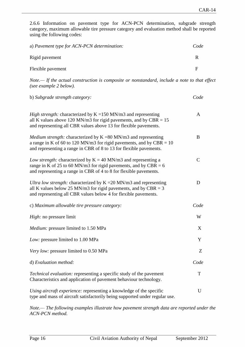
2.6.6 Information on pavement type for ACN-PCN determination, subgrade strength
category, maximum allowable tire pressure category and evaluation method shall be reported
using the following codes:
a) Pavement type for ACN-PCN determination: Code
Rigid pavement R
Flexible pavement F
Note.— If the actual construction is composite or nonstandard, include a note to that effect
(see example 2 below).
b) Subgrade strength category: Code
High strength: characterized by K =150 MN/m3 and representing A
all K values above 120 MN/m3 for rigid pavements, and by CBR = 15
and representing all CBR values above 13 for flexible pavements.
Medium strength: characterized by K =80 MN/m3 and representing B
a range in K of 60 to 120 MN/m3 for rigid pavements, and by CBR = 10
and representing a range in CBR of 8 to 13 for flexible pavements.
Low strength: characterized by K = 40 MN/m3 and representing a C
range in K of 25 to 60 MN/m3 for rigid pavements, and by CBR = 6
and representing a range in CBR of 4 to 8 for flexible pavements.
Ultra low strength: characterized by K =20 MN/m3 and representing D
all K values below 25 MN/m3 for rigid pavements, and by CBR = 3
and representing all CBR values below 4 for flexible pavements.
c) Maximum allowable tire pressure category: Code
High: no pressure limit W
Medium: pressure limited to 1.50 MPa X
Low: pressure limited to 1.00 MPa Y
Very low: pressure limited to 0.50 MPa Z
d) Evaluation method: Code
Technical evaluation: representing a specific study of the pavement T
Characteristics and application of pavement behaviour technology.
Using aircraft experience: representing a knowledge of the specific U
type and mass of aircraft satisfactorily being supported under regular use.
Note.— The following examples illustrate how pavement strength data are reported under the
ACN-PCN method.

CAR-14
Page 17 Civil Aviation Authority of Nepal September 2012
Example 1.— If the bearing strength of a rigid pavement, resting on a medium strength
subgrade, has been assessed by technical evaluation to be PCN 80 and there is no tire
pressure limitation, then the reported information would be:
PCN 80 / R / B / W / T
Example 2.— If the bearing strength of a composite pavement, behaving like a flexible
pavement and resting on a high strength subgrade, has been assessed by using aircraft
experience to be PCN 50 and the maximum tire pressure allowable is 1.00 MPa, then the
reported information would be:
PCN 50 / F / A / Y / U
Note.— Composite construction.
Example 3.— If the bearing strength of a flexible pavement, resting on a medium strength
subgrade, has been assessed by technical evaluation to be PCN 40 and the maximum
allowable tire pressure is 0.80 MPa, then the reported information would be:
PCN 40 / F / B / 0.80 MPa /T
Example 4.— If a pavement is subject to a B747-400 all-up mass limitation of 390 000 kg,
then the reported information would include the following note.
Note.— The reported PCN is subject to a B747-400 all-up mass limitation of 390 000 kg.
2.6.7 Recommendation.- Criteria should be established to regulate the use of a pavement by
an aircraft with an ACN higher than the PCN reported for that pavement in accordance with
2.6.2 and 2.6.3.
Note.— Attachment A, Section 19 details a simple method for regulating overload operations
while the ICAO Aerodrome Design Manual, Part 3 includes the descriptions of more detailed
procedures for evaluation of pavements and their suitability for restricted overload
operations.
2.6.8 The bearing strength of a pavement intended for aircraft of apron (ramp) mass equal to
or less than 5 700 kg shall be made available by reporting the following information:
a) maximum allowable aircraft mass; and
b) maximum allowable tire pressure.
Example: 4 000 kg/0.50 MPa.
2.7 Pre-flight altimeter check location
2.7.1 One or more pre-flight altimeter check locations shall be established for an aerodrome.
2.7.2 A pre-flight check location shall be located on an apron.
2.7.3 The elevation of a pre-flight altimeter check location shall be given as the average
elevation, rounded to the nearest metre or foot, of the area on which it is located. The
elevation of any portion of a pre-flight altimeter check location shall be within 3 m (10 ft) of
the average elevation for that location.

CAR-14
Page 18 Civil Aviation Authority of Nepal September 2012
2.8 Declared distances
The following distances shall be calculated to the nearest metre or foot for a runway intended
for use by international commercial air transport:
a) take-off run available;
b) take-off distance available;
c) accelerate-stop distance available; and
d) landing distance available.
Note.— Guidance on calculation of declared distances is given in Attachment A, Section 3.
2.9 Condition of the movement area and related facilities
2.9.1 Information on the condition of the movement area and the operational status of related
facilities shall be provided to the appropriate aeronautical information service units, and
similar information of operational significance to the air traffic services units, to enable those
units to provide the necessary information to arriving and departing aircraft. The information
shall be kept up to date and changes in conditions reported without delay.
2.9.2 The condition of the movement area and the operational status of related facilities shall
be monitored and reports on matters of operational significance or affecting aircraft
performance given, particularly in respect of the following:
a) construction or maintenance work;
b) rough or broken surfaces on a runway, a taxiway or an apron;
c) snow, slush or ice on a runway, a taxiway or an apron; d) water on a runway, a taxiway
or an apron;
e) snow banks or drifts adjacent to a runway, a taxiway or an apron;
f) anti-icing or de-icing liquid chemicals on a runway or a taxiway;
g) other temporary hazards, including parked aircraft;
h) failure or irregular operation of part or all of the aerodrome visual aids; and
i) failure of the normal or secondary power supply.
2.9.3 Inspections of the movement area shall be carried out each day at least once where the
code number is 1or 2 and at least twice where the code number is 3 or 4 in order to facilitate
compliance with 2.9.1 and 2.9.2.
Note.— Guidance on carrying out daily inspections of the movement area is given in the
ICAO Airport Services Manual, Part 8 and in the ICAO Manual of Surface Movement
Guidance and Control Systems (SMGCS).

CAR-14
Page 19 Civil Aviation Authority of Nepal September 2012
Water on a runway
2.9.4 Whenever water is present on a runway, a description of the runway surface conditions
on the centre half of the width of the runway, including the possible assessment of water
depth, where applicable, shall be made available using the following terms:
DAMP — the surface shows a change of colour due to moisture.
WET — the surface is soaked but there is no standing water.
WATER PATCHES — significant patches of standing water are visible.
FLOODED — extensive standing water is visible.
2.9.5 Information that a runway or portion thereof may be slippery when wet shall be made
available.
2.9.6 A runway or portion thereof shall be determined as being slippery when wet when the
measurements specified in 10.2.3 show that the runway surface friction characteristics as
measured by a continuous friction measuring device are below the minimum friction level
specified in the Attachment A, Table A – 1.
Note.— Guidance on determining and expressing the minimum friction level is provided in
Attachment A, Section 7.
2.9.7 The minimum friction levels specified in the Attachment A, Table A – 1 for the
different types of friction measuring devices shall be taken for reporting slippery runway
conditions.
2.9.8 Recommendation.- When it is suspected that a runway may become slippery under
unusual conditions, then additional measurements should be made when such conditions
occur, and information on the runway surface friction characteristics made available when
these additional measurements show that the runway or a portion thereof has become
slippery.
Snow, slush or ice on a runway
Note 1.— The intent of these specifications is to satisfy the SNOWTAM and NOTAM
promulgation requirements contained in Annex 15.
Note 2.— Runway surface condition sensors may be used to detect and continuously
display current or predicted information on surface conditions such as the presence of
moisture, or imminent formation of ice on pavements.
2.9.9 Recommendation.— Whenever a runway is affected by snow, slush or ice, and it has
not been possible to clear the precipitant fully, the condition of the runway should be
assessed, and the friction coefficient measured.
Note.— Guidance on determining and expressing the friction characteristics of snow- and
ice-covered paved surfaces is provided in Attachment A, Section 6.
2.9.10 Recommendation.— The readings of the friction measuring device on snow-,
slush-, or ice-covered surfaces should adequately correlate with the readings of one other
such device.
Note.— The principal aim is to measure surface friction in a manner that is relevant to the
CAR-14
Page 20 Civil Aviation Authority of Nepal September 2012
friction experienced by an aircraft tire, thereby providing correlation between the friction
measuring device and aircraft braking performance.
2.9.11 Recommendation.— Whenever dry snow, wet snow or slush is present on a runway,
an assessment of the mean depth over each third of the runway should be made to an
accuracy of approximately 2 cm for dry snow, 1 cm for wet snow and 0.3 cm for slush.
2.10 Disabled aircraft removal
Note.— See 9.3 for information on disabled aircraft removal services.
2.10.1 The telephone/telex number(s) of the office of the aerodrome coordinator of operations
for the removal of an aircraft disabled on or adjacent to the movement area shall be made
available, on request, to aircraft operators.
2.10.2 Recommendation.- Information concerning the capability to remove an aircraft
disabled on or adjacent to the movement area should be made available.
Note.— The capability to remove a disabled aircraft may be expressed in terms of the largest
type of aircraft which the aerodrome is equipped to remove.
2.11 Rescue and fire fighting
Note.— See 9.2 for information on rescue and fire fighting services.
2.11.1 Information concerning the level of protection provided at an aerodrome for aircraft
rescue and fire fighting purposes shall be made available.
2.11.2 Recommendation.- The level of protection normally available at an aerodrome
should be expressed in terms of the category of the rescue and fire fighting services as
described in 9.2 and in accordance with the types and amounts of extinguishing agents
normally available at the aerodrome.
2.11.3 Significant changes in the level of protection normally available at an aerodrome for
rescue and fire fighting shall be notified to the appropriate air traffic services units and
aeronautical information units to enable those units to provide the necessary information to
arriving and departing aircraft. When such a change has been corrected, the above units shall
be advised accordingly.
Note.— A significant change in the level of protection is considered to be a change in the
category of the rescue and fire fighting service from the category normally available at the
aerodrome, resulting from a change in availability of extinguishing agents, equipment to
deliver the agents or personnel to operate the equipment, etc.
2.11.4 Recommendation.- A significant change should be expressed in terms of the new
category of the rescue and fire fighting service available at the aerodrome.
2.12 Visual approach slope indicator systems
The following information concerning a visual approach slope indicator system installation
shall be made available:
a) associated runway designation number;

CAR-14
Page 21 Civil Aviation Authority of Nepal September 2012
b) type of system according to 5.3.5.2. for an AT-VASIS, PAPI or APAPI installation, the
side of the runway on which the lights are installed, i.e. left or right, shall be given;
c) where the axis of the system is not parallel to the runway centre line, the angle of
displacement and the direction of displacement, i.e. left or right shall be indicated;
d) nominal approach slope angle(s). For a T-VASIS or an AT-VASIS this shall be angle θ
according to the formula in Figure 5-17 and for a PAPI and an APAPI this shall be angle
(B + C) /2 and (A + B) /2, respectively as in Figure 5-19; and
e) minimum eye height(s) over the threshold of the on-slope signal(s). For a T-VASIS or an
AT-VASIS this shall be the lowest height at which only the wing bar(s) are visible; however,
the additional heights at which the wing bar(s) plus one, two or three fly down light units
come into view may also be reported if such information would be of benefit to aircraft using
the approach. For a PAPI this shall be the setting angle of the third unit from the runway
minus 2′, i.e. angle B minus 2′, and for an APAPI this shall be the setting angle of the unit
farther from the runway minus 2′, i.e. angle A minus 2′.
2.13 Coordination between aeronautical information services and aerodrome
authorities
2.13.1 To ensure that aeronautical information services units obtain information to enable
them to provide up-to-date pre-flight information and to meet the need for in-flight
information, arrangements shall be made between aeronautical information services and
aerodrome authorities responsible for aerodrome services to report to the responsible
aeronautical information services unit, with a minimum of delay:
a) information on aerodrome conditions (ref. 2.9, 2.10, 2.11 and 2.12);
b) the operational status of associated facilities, services and navigation aids within their area
of responsibility;
c) any other information considered to be of operational significance.
2.13.2 Before introducing changes to the air navigation system, due account shall be taken by
the services responsible for such changes of the time needed by the aeronautical information
service for the preparation, production and issue of relevant material for promulgation. To
ensure timely provision of the information to the aeronautical information service, close
coordination between those services concerned is therefore required.
2.13.3 Of a particular importance are changes to aeronautical information that affect charts
and/or computer based navigation systems which qualify to be notified by the aeronautical
information regulation and control (AIRAC) system. The predetermined, internationally
agreed AIRAC effective dates in addition to 14 days postage time shall be observed by the
responsible aerodrome services when submitting the raw information/data to aeronautical
information services.
2.13.4 The aerodrome services responsible for the provision of raw aeronautical
information/data to the aeronautical information services shall do that while taking into
account accuracy and integrity requirements for aeronautical data as specified in Appendix 5
to this document.
Note 1.— Specifications for the issue of a NOTAM are contained in Annex 15, Chapter 5
and Appendices 6 and 2, respectively.
Note 2.— AIRAC information is distributed by the AIS at least 42 days in advance of the

CAR-14
Page 22 Civil Aviation Authority of Nepal September 2012
AIRAC effective dates with the objective of reaching recipients at least 28 days in advance
of the effective date.
Note 3.— The schedule of the predetermined internationally agreed AIRAC common
effective dates at intervals of 28 days, including 6 November 1997 and guidance for the
AIRAC use are contained in the ICAO Aeronautical Information Services Manual (Doc
8126, Chapter 2).

CAR-14
Page 23 Civil Aviation Authority of Nepal September 2012
CHAPTER -3
PHYSICAL CHARACTERISTICS
3.1 Runways
Number and orientation of runways
Many factors affect the determination of the orientation, siting and number of runways. One
important factor is the usability factor, as determined by the wind distribution, which is
specified hereunder. Another important factor is the alignment of the runway to facilitate the
provision of approaches conforming to the approach surface specifications of Chapter 4. In
Attachment A, Section 1, information is given concerning these and other factors.
When a new instrument runway is being located, particular attention needs to be given to
areas over which aeroplanes will be required to fly when following instrument approach and
missed approach procedures, so as to ensure that obstacles in these areas or other factors
will not restrict the operation of the aeroplanes for which the runway is intended.
3.1.1 Recommendation.- The number and orientation of runways at an aerodrome should be
such that the usability factor of the aerodrome is not less than 95 per cent for the aeroplanes
that the aerodrome is intended to serve.
3.1.2 Recommendation.- The siting and orientation of runways at an aerodrome should,
where possible, be such that the arrival and departure tracks minimize interference with
areas approved for residential use and other noise sensitive areas close to the aerodrome in
order to avoid future noise problems.
Note.- Guidance on how to address noise problems is provided in the ICAO Airport
Planning Manual, Part 2, and in Guidance on the Balanced Approach to Aircraft Noise
Management (Doc 9829).
3.1.3 Choice of maximum permissible cross-wind components
Recommendation.- In the application of 3.1.1 it should be assumed that landing or take-off
of aeroplanes is, in normal circumstances, precluded when the cross-wind component
exceeds:
- 37 km/h (20 kt) in the case of aeroplanes whose reference field length is 1 500 m or over,
except that when poor runway braking action owing to an insufficient longitudinal coefficient
of friction is experienced with some frequency, a cross-wind component not exceeding 24
km/h (13 kt) should be assumed;
- 24 km/h (13 kt) in the case of aeroplanes whose reference field length is 1 200 m or up to
but not including 1 500 m; and
- 19 km/h (10 kt) in the case of aeroplanes whose reference field length is less than 1 200 m.

CAR-14
Page 24 Civil Aviation Authority of Nepal September 2012
Note.— In Attachment A, Section 1, guidance is given on factors affecting the calculation of
the estimate of the usability factor and allowances which may have to be made to take
account of the effect of unusual circumstances.
3.1.4 Data to be used
Recommendation.- The selection of data to be used for the calculation of the usability factor
should be based on reliable wind distribution statistics that extend over as long a period as
possible, preferably of not less than five years. The observations used should be made at least
eight times daily and spaced at equal intervals of time.
Note.— These winds are mean winds. Reference to the need for some allowance for gusty
conditions is made in Attachment A, Section 1.
Location of threshold
3.1.5 Recommendation.- A threshold should normally be located at the extremity of a
runway unless operational considerations justify the choice of another location.
Note.— Guidance on the siting of the threshold is given in Attachment A, Section 10.
3.1.6 Recommendation.- When it is necessary to displace a threshold, either permanently or
temporarily, from its normal location, account should be taken of the various factors which
may have a bearing on the location of the threshold. Where this displacement is due to an
unserviceable runway condition, a cleared and graded area of at least 60 m in length should
be available between the unserviceable area and the displaced threshold. Additional distance
should also be provided to meet the requirements of the runway end safety area as
appropriate.
Note.— Guidance on factors which may be considered in the determination of the location of
a displaced threshold is given in Attachment A, Section 10.
Actual length of runways
3.1.7 Primary runway
Recommendation.- Except as provided in 3.1.9 the actual runway length to be provided for
a primary runway should be adequate to meet the operational requirements of the aeroplanes
for which the runway is intended and shall be not less than the longest length determined by
applying the corrections for local conditions to the operations and performance
characteristics of the relevant aeroplanes.
Note 1.— This specification does not necessarily mean providing for operations by the
critical aeroplane at its maximum mass.
Note 2.— Both take-off and landing requirements need to be considered when determining
the length of runway to be provided and the need for operations to be conducted in both
directions of the runway.
Note 3.— Local conditions that may need to be considered include elevation, temperature,
runway slope, humidity and the runway surface characteristics.

CAR-14
Page 25 Civil Aviation Authority of Nepal September 2012
Note 4.— When performance data on aeroplanes for which the runway is intended are not
known, guidance on the determination of the actual length of a primry runway by application
of general correction factors is given in the ICAO Aerodrome Design Manual, Part 1.
3.1.8 Secondary runway
Recommendation.- The length of a secondary runway should be determined similarly to
primary runways except that it needs only to be adequate for those aeroplanes which require
to use that secondary runway in addition to the other runway or runways in order to obtain a
usability factor of at least 95 per cent.
3.1.9 Runways with stopways or clearways
Recommendation.- Where a runway is associated with a stopway or clearway, an actual
runway length less than that resulting from application of 3.1.7 or 3.1.8, as appropriate, may
be considered satisfactory, but in such a case any combination of runway, stopway and
clearway provided should permit compliance with the operational requirements for take-off
and landing of the aeroplanes the runway is intended to serve.
Note.— Guidance on use of stopways and clearways is given in Attachment A, Section 2.
Width of runways
3.1.10 The width of a runway shall not be less than the appropriate dimension specified in the
following tabulation:
a. The width of a precision approach runway should be not less than 30 m where the code
number is 1 or 2.
Note 1.— The combinations of code numbers and letters for which widths are specified have
been developed for typical aeroplane characteristics.
Note 2.— Factors affecting runway width are given in the ICAO Aerodrome Design Manual,
Part 1.
Minimum distance between parallel runways
3.1.11 Where parallel non-instrument runways are intended for simultaneous use, the
minimum distance between their centre lines shall be:
- 210 m where the higher code number is 3 or 4;
- 150 m where the higher code number is 2; and
- 120 m where the higher code number is 1

CAR-14
Page 26 Civil Aviation Authority of Nepal September 2012
Note.— Procedures for wake turbulence categorization of aircraft and wake turbulence
separation minima are contained in the ICAO Procedures for Air Navigation Services — Air
Traffic Management (PANS-ATM), Doc 4444, Chapter 4, 4.9 and Chapter 5, 5.8,
respectively.
3.1.12 Where parallel instrument runways are intended for simultaneous use subject to
conditions specified in the ICAO PANS-ATM (Doc 4444) and the ICAO PANS-OPS (Doc
8168), Part 1, the minimum distance between their centre lines shall be:
- 1 035 m for independent parallel approaches;
- 915 m for dependent parallel approaches;
- 760 m for independent parallel departures;
- 760 m for segregated parallel operations;
except that:
a) for segregated parallel operations the specified minimum distance:
1) may be decreased by 30 m for each 150 m that the arrival runway is staggered toward
the arriving aircraft, to a minimum of 300 m; and
2) should be increased by 30 m for each 150 m that the arrival runway is staggered away
from the arriving aircraft;
b) for independent parallel approaches, combinations of minimum distances and associated
conditions other than those specified in the ICAO PANS-ATM (Doc 4444) may be
applied when it is determined that such combinations would not adversely affect the
safety of aircraft operations.
Note.— Procedures and facilities requirements for simultaneous operations on parallel or
near-parallel instrument runways are contained in the ICAO PANS-ATM (Doc 4444),
Chapter 6 and the ICAO PANS-OPS (Doc 8168), Part 1, Part VII and Part 1I, Parts II and
III and relevant guidance is contained in the ICAO Manual of Simultaneous Operations on
Parallel or Near-Parallel Instrument Runways (Doc 9643).
Slopes on runways
3.1.13 Longitudinal slopes
Recommendation.- The slope computed by dividing the difference between the maximum
and minimum elevation along the runway centre line by the runway length should not exceed:
— 1 per cent where the code number is 3 or 4; and
— 2 per cent where the code number is 1 or 2.
3.1.14 Recommendation.- Along no portion of a runway should the longitudinal slope
exceed:
- 1.25 per cent where the code number is 4, except that for the first and last quarter of the
length of the runway the longitudinal slope should not exceed 0.8 per cent;
- 1.5 per cent where the code number is 3, except that for the first and last quarter of the
length of a precision approach runway category II or III the longitudinal slope should
not exceed 0.8 per cent; and
- 2 per cent where the code number is 1 or 2.

CAR-14
Page 27 Civil Aviation Authority of Nepal September 2012
3.1.15 Longitudinal slope changes
Recommendation.- Where slope changes cannot be avoided, a slope change between two
consecutive slopes should not exceed:
- 1.5 per cent where the code number is 3 or 4; and
- 2 per cent where the code number is 1 or 2.
Note.— Guidance on slope changes before a runway is given in Attachment A, Section 4.
3.1.16 Recommendation.- The transition from one slope to another should be accomplished
by a curved surface with a rate of change not exceeding:
- 0.1 per cent per 30 m (minimum radius of curvature of 30 000 m) where the code
number is 4;
- 0.2 per cent per 30 m (minimum radius of curvature of 15 000 m) where the code
number is 3; and
- 0.4 per cent per 30 m (minimum radius of curvature of 7 500 m) where the code
number is 1 or 2.
3.1.17 Sight distance
Recommendation.- Where slope changes cannot be avoided, they should be such that there
will be an unobstructed line of sight from:
- any point 3 m above a runway to all other points 3 m above the runway within a
distance of at least half the length of the runway where the code letter is C, D, E or F.
- any point 2 m above a runway to all other points 2 m above the runway within a
distance of at least half the length of the runway where the code letter is B; and
- any point 1.5 m above a runway to all other points 1.5 m above the runway within a
distance of at least half the length of the runway where the code letter is A.
Note.— Consideration will have to be given to providing an unobstructed line of sight over
the entire length of a single runway where a full-length parallel taxiway is not available.
Where an aerodrome has intersecting runways, additional criteria on the line of sight of the
intersection area would need to be considered for operational safety. See the ICAO
Aerodrome Design Manual, Part 1.
3.1.18 Distance between slope changes
Recommendation.- Undulations or appreciable changes in slopes located close together
along a runway should be avoided. The distance between the points of intersection of two
successive curves should not be less than:
a) the sum of the absolute numerical values of the corresponding slope changes multiplied by
the appropriate value as follows:
- 30 000 m where the code number is 4;
- 15 000 m where the code number is 3; and

CAR-14
Page 28 Civil Aviation Authority of Nepal September 2012
- 5 000 m where the code number is 1 or 2; or
b) 45 m;
whichever is greater.
Note.— Guidance on implementing this specification is given in Attachment A, Section 4.
3.1.19 Transverse slopes
Recommendation.- To promote the most rapid drainage of water, the runway surface
should, if practicable, be cambered except where a single crossfall from high to low in the
direction of the wind most frequently associated with rain would ensure rapid drainage. The
transverse slope should ideally be:
- 1.5 per cent where the code letter is C, D, E or F; and
- 2 per cent where the code letter is A or B;
but in any event should not exceed 1.5 per cent or 2 per cent, as applicable, nor be less than
1 per cent except at runway or taxiway intersections where flatter slopes may be necessary.
For a cambered surface the transverse slope on each side of the centre line should be
symmetrical.
Note - On wet runways with cross-wind conditions the problem of aquaplaning from poor
drainage is apt to be accentuated. In Attachment A, Section 7, information is given
concerning this problem and other relevant factors.
3.1.20 The transverse slope shall be substantially the same throughout the length of a runway
except at an intersection with another runway or a taxiway where an even transition should be
provided taking account of the need for adequate drainage.
Note.— Guidance on transverse slope is given in the ICAO Aerodrome Design Manual, Part
3.
Strength of runways
3.1.21 Recommendation.- A runway should be capable of withstanding the traffic of
aeroplanes the runway is intended to serve.
Surface of runways
3.1.22 The surface of a runway shall be constructed without irregularities that would result in
loss in friction characteristics or otherwise adversely affect the take-off or landing of an
aeroplane.
Note 1 - Surface irregularities may adversely affect the take-off or landing of an aeroplane by
causing excessive bouncing, pitching, vibration, or other difficulties in the control of an
aeroplane.
CAR-14
Page 29 Civil Aviation Authority of Nepal September 2012
Note 2 - Guidance on design tolerances and other information is given in Attachment A,
Section 5. Additional guidance is included in the ICAO Aerodrome Design Manual, Part 3.
3.1.23 The surface of a paved runway shall be so constructed as to provide good friction
characteristics when the runway is wet.
3.1.24 Recommendation.- The measurements of the friction characteristics of a new or
resurfaced runway should be made with a continuous friction measuring device using self-
wetting features in order to assure that the design objectives with respect to its friction
characteristics have been achieved.
Note.— Guidance on friction characteristics of new runway surfaces is given in Attachment
A, Section 7. Additional guidance is included in the ICAO Airport Services Manual, Part 2.
3.1.25 Recommendation.- The average surface texture depth of a new surface should be not
less than 1.0 mm.
Note 1 - This normally requires some form of special surface treatment.
Note 2 - Guidance on methods used to measure surface texture is given in the ICAO Airport
Services Manual, Part 2.
3.1.26 Recommendation.- When the surface is grooved or scored, the grooves or scorings
should be either perpendicular to the runway centre line or parallel to non-perpendicular
transverse joints, where applicable.
Note.— Guidance on methods for improving the runway surface texture is given in the ICAO
Aerodrome Design Manual, Part 3.
3.2 Runway shoulders
General
Note.— Guidance on characteristics and treatment of runway shoulders is given in
Attachment A, Section 8, and in the ICAO Aerodrome Design Manual, Part 1.
3.2.1 The runway shoulders shall be provided for a runway where the code letter is D or E,
and the runway width is less than 60 m.
3.2.2 The runway shoulders shall be provided for a runway where the code letter is F.
Width of runway shoulders
3.2.3 The runway shoulders shall extend symmetrically on each side of the runway so that the
overall width of the runway and its shoulders is not less than:
- 60 m where the code letter is D or E; and
- 75 m where the code letter is F.
Slopes on runway shoulders
3.2.4 Recommendation.- The surface of the shoulder that abuts the runway should be flush
with the surface of the runway and its transverse slope should not exceed 2.5 per cent.

CAR-14
Page 30 Civil Aviation Authority of Nepal September 2012
Strength of runway shoulders
3.2.5 Recommendation.- A runway shoulder should be prepared or constructed so as to be
capable, in the event of an aeroplane running off the runway, of supporting the aeroplane
without inducing structural damage to the aeroplane and of supporting ground vehicles
which may operate on the shoulder.
Note.— Guidance on strength of runway shoulders is given in the ICAO Aerodrome Design
Manual, Part 1.
3.3 Runway turn pads
General
3.3.1 Where the end of a runway is not served by a taxiway or a taxiway turnaround and
where the code letter is D, E or F, a runway turn pad shall be provided to facilitate a 180-
degree turn of aeroplanes. (See Figure 3-1.)
3.3.2 Recommendation.- Where the end of a runway is not served by a taxiway or a taxiway
turnaround and where the code letter is A, B or C, a runway turn pad should be provided to
facilitate a 180-degree turn of aeroplanes.
Note 1.— Such areas may also be useful if provided along a runway to reduce taxiing time
and distance for aeroplanes which may not require the full length of the runway.
Note 2.— Guidance on the design of the runway turn pads is available in the ICAO
Aerodrome Design Manual, Part 1. Guidance on taxiway turnaround as an alternate facility
is available in the ICAO Aerodrome Design Manual, Part 2.
3.3.3 Recommendation.- The runway turn pad may be located on either the left or right side
of the runway and adjoining the runway pavement at both ends of the runway and at some
intermediate locations where deemed necessary.
Note - The initiation of the turn would be facilitated by locating the turn pad on the left side
of the runway, since the left seat is the normal position of the pilot-in-command.
3.3.4 Recommendation.- The intersection angle of the runway turn pad with the runway
should not exceed 30 degrees.

CAR-14
Page 31 Civil Aviation Authority of Nepal September 2012
3.3.5 Recommendation.- The nose wheel steering angle to be used in the design of the
runway turn pad should not exceed 45 degrees.
3.3.6 The design of a runway turn pad shall be such that, when the cockpit of the aeroplane
for which the turn pad is intended remains over the turn pad marking, the clearance distance
between any wheel of the aeroplane landing gear and the edge of the turn pad shall be not less
than that given by the following tabulation:
Code letter Clearance
A 1.5 m
B 2.25 m
C 3 m if the turn pad is intended to be used by aeroplanes with a wheel
base less than 18 m;
4.5 m if the turn pad is intended to be used by aeroplanes with a
wheel base equal to or greater than 18 m.
D 4.5 m
E 4.5 m
F 4.5 m
Note.— Wheel base means the distance from the nose gear to the geometric centre of the
main gear.
3.3.7 Recommendation.- Where severe weather conditions and resultant lowering of surface
friction characteristics prevail, a larger wheel-to-edge clearance of 6 m should be provided
where the code letter is E or F.
Slopes on runway turn pads
3.3.8 Recommendation.- The longitudinal and transverse slopes on a runway turn pad
should be sufficient to prevent the accumulation of water on the surface and facilitate rapid
drainage of surface water. The slopes should be the same as those on the adjacent runway
pavement surface.
Strength of runway turn pads
3.3.9 The strength of a runway turn pad shall be at least equal to that of the adjoining runway
which it serves, due consideration being given to the fact that the turn pad will be subjected to
slow-moving traffic making hard turns and consequent higher stresses on the pavement.
Note.— Where a runway turn pad is provided with flexible pavement, the surface would need
to be capable of withstanding the horizontal shear forces exerted by the main landing gear
tires during turning manoeuvres.
CAR-14
Page 32 Civil Aviation Authority of Nepal September 2012
Surface of runway turn pads
3.3.10 The surface of a runway turn pad shall not have surface irregularities that may cause
damage to an aeroplane using the turn pad.
3.3.11 Recommendation.- The surface of a runway turn pad should be so constructed as to
provide good friction characteristics for aeroplanes using the facility when the surface is wet.
Shoulders for runway turn pads
3.3.12 Recommendation.- The runway turn pads should be provided with shoulders of such
width as is necessary to prevent surface erosion by the jet blast of the most demanding
aeroplane for which the turn pad is intended, and any possible foreign object damage to the
aeroplane engines.
Note.— As a minimum, the width of the shoulders would need to cover the outer engine of the
most demanding aeroplane and thus may be wider than the associated runway shoulders.
3.3.13 Recommendation.- The strength of runway turn pad shoulders should be capable of
withstanding the occasional passage of the aeroplane it is designed to serve without inducing
structural damage to the aeroplane and to the supporting ground vehicles that may operate
on the shoulder.
3.4 Runway strips
General
3.4.1 A runway and any associated stopways shall be included in a strip.
Length of runway strips
3.4.2 A strip shall extend beyond the end of the runway or stopway for a distance of at least:
- 60 m where the code number is 2, 3 or 4;
- 60 m where the code number is 1 and the runway is an instrument one; and
- 30 m where the code number is 1 and the runway is a non-instrument one.
Width of runway strips
3.4.3 A strip including a precision approach runway shall, wherever practicable, extend
laterally to a distance of at least:
- 150 m where the code number is 3 or 4; and
- 75 m where the code number is 1 or 2;
on each side of the centre line of the runway and its extended centre line throughout the
length of the strip.
CAR-14
Page 33 Civil Aviation Authority of Nepal September 2012
3.4.4 Recommendation.- A strip including a non-precision approach runway should extend
laterally to a distance of at least:
- 150 m where the code number is 3 or 4; and
- 75 m where the code number is 1 or 2;
on each side of the centre line of the runway and its extended centre line throughout the
length of the strip.
3.4.5 Recommendation.- A strip including a non-instrument runway should extend on each
side of the centre line of the runway and its extended centre line throughout the length of the
strip, to a distance of at least:
- 75 m where the code number is 3 or 4;
- 40 m where the code number is 2; and
- 30 m where the code number is 1.
Objects on runway strips
Note - See 9.9 for information regarding siting of equipment and installations on runway
strips.
3.4.6 Recommendation.- An object situated on a runway strip which may endanger
aeroplanes should be regarded as an obstacle and should, as far as practicable, be removed.
3.4.7 No fixed object, other than visual aids required for air navigation purposes and
satisfying the relevant frangibility requirement in Chapter 5, shall be permitted on a runway
strip:
a) within 77.5 m of the runway centre line of a precision approach runway category I,
II or III where the code number is 4 and the code letter is F; or
b) within 60 m of the runway centre line of a precision approach runway category I, II
or III where the code number is 3 or 4; or
c) within 45 m of the runway centre line of a precision approach runway category I
where the code number is 1 or 2.
No mobile object shall be permitted on this part of the runway strip during the use of the
runway for landing or take-off.
Grading of runway strips
3.4.8 Recommendation.- That portion of a strip of an instrument runway within a distance
of at least:
- 75 m where the code number is 3 or 4; and
- 40 m where the code number is 1 or 2;

CAR-14
Page 34 Civil Aviation Authority of Nepal September 2012
from the centre line of the runway and its extended centre line should provide a graded area
for aeroplanes which the runway is intended to serve in the event of an aeroplane running off
the runway.
Note.— Guidance on grading of a greater area of a strip including a precision approach
runway where the code number is 3 or 4 is given in Attachment A, Section 8.
3.4.9 Recommendation.- That portion of a strip of a non-instrument runway within a
distance of at least:
- 75 m where the code number is 3 or 4;
- 40 m where the code number is 2; and
- 30 m where the code number is 1;
from the centre line of the runway and its extended centre line should provide a graded area
for aeroplanes which the runway is intended to serve in the event of an aeroplane running off
the runway.
3.4.10 The surface of that portion of a strip that abuts a runway, shoulder or stopway shall be
flush with the surface of the runway, shoulder or stopway.
3.4.11 Recommendation.- That portion of a strip to at least 30 m before a threshold should
be prepared against blast erosion in order to protect a landing aeroplane from the danger of
an exposed edge.
Slopes on runway strips
3.4.12 Longitudinal slopes
Recommendation.- A longitudinal slope along that portion of a strip to be graded should not
exceed:
- 1.5 per cent where the code number is 4;
- 1.75 per cent where the code number is 3; and
- 2 per cent where the code number is 1 or 2.
3.4.13 Longitudinal slope changes
It is recommended that slope changes on that portion of a strip to be graded should be as
gradual as practicable and abrupt changes or sudden reversals of slopes avoided.
3.4.14 Transverse slopes
Recommendation.- Transverse slopes on that portion of a strip to be graded should be
adequate to prevent the accumulation of water on the surface but should not exceed:
- 2.5 per cent where the code number is 3 or 4; and

CAR-14
Page 35 Civil Aviation Authority of Nepal September 2012
- 3 per cent where the code number is 1 or 2;
except that to facilitate drainage the slope for the first 3m outward from the runway, shoulder
or stopway edge should be negative as measured in the direction away from the runway and
may be as great as 5 per cent.
3.4.15 Recommendation.- The transverse slopes of any portion of a strip beyond that to be
graded should not exceed an upward slope of 5 per cent as measured in the direction away
from the runway.
Strength of runway strips
3.4.16 Recommendation.- That portion of a strip of an instrument runway within a distance
of at least:
- 75 m where the code number is 3 or 4; and
- 40 m where the code number is 1 or 2;
from the centre line of the runway and its extended centre line should be so prepared or
constructed as to minimize hazards arising from differences in load bearing capacity to
aeroplanes which the runway is intended to serve in the event of an aeroplane running off the
runway.
Note.— Guidance on preparation of runway strips is given in the ICAO Aerodrome Design
Manual, Part 1.
3.4.17 Recommendation.- That portion of a strip containing a non-instrument runway within
a distance of at least:
- 75 m where the code number is 3 or 4;
- 40 m where the code number is 2; and
- 30 m where the code number is 1;
from the centre line of the runway and its extended centre line should be so prepared or
constructed as to minimize hazards arising from differences in load bearing capacity to
aeroplanes which the runway is intended to serve in the event of an aeroplane running off the
runway.
3.5 Runway end safety areas
General
3.5.1 A runway end safety area shall be provided at each end of a runway strip where:
- the code number is 3 or 4; and
- the code number is 1 or 2 and the runway is an instrument one.
Note.— Guidance on runway end safety areas is given in Attachment A, Section 9.

CAR-14
Page 36 Civil Aviation Authority of Nepal September 2012
Dimensions of runway end safety areas
3.5.2 A runway end safety area shall extend from the end of a runway strip to a distance of at
least 90 m.
3.5.3 Recommendation.- A runway end safety area should, as far as practicable, extend
from the end of a runway strip to a distance of at least:
- 240 m where the code number is 3 or 4; and
- 120 m where the code number is 1 or 2.
3.5.4 The width of a runway end safety area shall be at least twice that of the associated
runway.
3.5.5 Recommendation.- The width of a runway end safety area should, wherever
practicable, be equal to that of the graded portion of the associated runway strip.
Objects on runway end safety areas
Note.— See 9.9 for information regarding siting of equipment and installations on runway
end safety areas.
3.5.6 Recommendation.- An object situated on a runway end safety area which may
endanger aeroplanes should be regarded as an obstacle and should, as far as practicable, be
removed.
Clearing and grading of runway end safety areas
3.5.7 Recommendation.- A runway end safety area should provide a cleared and graded
area for aeroplanes which the runway is intended to serve in the event of an aeroplane
undershooting or overrunning the runway.
Note.— The surface of the ground in the runway end safety area does not need to be prepared
to the same quality as the runway strip. See, however, 3.5.11.
Slopes on runway end safety areas
3.5.8 General
Recommendation.- The slopes of a runway end safety area should be such that no part of
the runway end safety area penetrates the approach or take-off climb surface.
3.5.9 Longitudinal slopes
Recommendation.- The longitudinal slopes of a runway end safety area should not exceed a
downward slope of 5 percent. Longitudinal slope changes should be as gradual as
practicable and abrupt changes or sudden reversals of slopes avoided.

CAR-14
Page 37 Civil Aviation Authority of Nepal September 2012
3.5.10 Transverse slopes
Recommendation.- The transverse slopes of a runway end safety area should not exceed an
upward or downward slope of 5 per cent. Transitions between differing slopes should be as
gradual as practicable.
Strength of runway end safety areas
3.5.11 Recommendation.- A runway end safety area should be so prepared or constructed
as to reduce the risk of damage to an aeroplane undershooting or overrunning the runway,
enhance aeroplane deceleration and facilitate the movement of rescue and fire fighting
vehicles as required in 9.2.26 to 9.2.28.
Note.— Guidance on strength of a runway end safety area is given in the ICAO Aerodrome
Design Manual, Part 1.
3.6 Clearways
Note.— The inclusion of detailed specifications for clearways in this section is not intended
to imply that a clearway has to be provided. Attachment A, Section 2 provides information on
the use of clearways.
Location of clearways
3.6.1 Recommendation.- The origin of a clearway should be at the end of the take-off run
available.
Length of clearways
3.6.2 Recommendation.- The length of a clearway should not exceed half the length of the
take-off run available.
Width of clearways
3.6.3 Recommendation.- A clearway should extend laterally to a distance of at least 75 m on
each side of the extended centre line of the runway.
Slopes on clearways
3.6.4 Recommendation.- The ground in a clearway should not project above a plane having
an upward slope of 1.25 per cent, the lower limit of this plane being a horizontal line which:
a) is perpendicular to the vertical plane containing the runway centre line; and
b) passes through a point located on the runway centre line at the end of the
take-off run available.
Note.— Because of transverse or longitudinal slopes on a runway, shoulder or strip, in
certain cases the lower limit of the clearway plane specified above may be below the
corresponding elevation of the runway, shoulder or strip. It is not intended that these
surfaces be graded to conform with the lower limit of the clearway plane nor is it intended
that terrain or objects which are above the clearway plane beyond the end of the strip but
below the level of the strip be removed unless it is considered they may endanger aeroplanes.

CAR-14
Page 38 Civil Aviation Authority of Nepal September 2012
3.6.5 Recommendation.- Abrupt upward changes in slope should be avoided when the slope
on the ground in a clearway is relatively small or when the mean slope is upward. In such
situations, in that portion of the clearway within a distance of 22.5 m or half the runway
width whichever is greater on each side of the extended centre line, the slopes, slope changes
and the transition from runway to clearway should generally conform with those of the
runway with which the clearway is associated.
Objects on clearways
Note.— See 9.9 for information regarding siting of equipment and installations on clearways.
3.6.6 Recommendation.- An object situated on a clearway which may endanger aeroplanes
in the air should be regarded as an obstacle and should be removed.
3.7 Stopways
Note.— The inclusion of detailed specifications for stopways in this section is not intended to
imply that a stopway has to be provided. Attachment A, Section 2 provides information on the
use of stopways.
Width of stopways
3.7.1 A stopway shall have the same width as the runway with which it is associated.
Slopes on stopways
3.7.2 Recommendation.- Slopes and changes in slope on a stopway, and the transition from
a runway to a stopway, should comply with the specifications of 3.1.13 to 3.1.19 for the
runway with which the stopway is associated except that:
a) the limitation in 3.1.14 of a 0.8 per cent slope for the first and last quarter of
the length of a runway need not be applied to the stopway; and
b) at the junction of the stopway and runway and along the stopway the
maximum rate of slope change may be 0.3 per cent per 30 m (minimum radius
of curvature of 10 000 m) for a runway where the code number is 3 or 4.
Strength of stopways
3.7.3 Recommendation.- A stopway should be prepared or constructed so as to be capable,
in the event of an abandoned take-off, of supporting the aeroplane which the stopway is
intended to serve without inducing structural damage to the aeroplane.
Note.— Attachment A, Section 2 presents guidance relative to the support capability of a
stopway.

CAR-14
Page 39 Civil Aviation Authority of Nepal September 2012
Surface of stopways
3.7.4 Recommendation.- The surface of a paved stopway should be so constructed as to
provide a good coefficient of friction to be compatible with that of the associated runway
when the stopway is wet.
3.7.5 Recommendation.- The friction characteristics of an unpaved stopway should not be
substantially less than that of the runway with which the stopway is associated.
3.8 Radio altimeter operating area
General
3.8.1 Recommendation.- A radio altimeter operating area should be established in the pre-
threshold area of a precision approach runway.
Length of the area
3.8.2 Recommendation.- A radio altimeter operating area should extend before the
threshold for a distance of at least 300 m.
Width of the area
3.8.3 Recommendation.- A radio altimeter operating area should extend laterally, on each
side of the extended centre line of the runway, to a distance of 60 m, except that, when special
circumstances so warrant, the distance may be reduced to no less than 30 m if an
aeronautical study indicates that such reduction would not affect the safety of operations of
aircraft.
Longitudinal slope changes
3.8.4 Recommendation.- On a radio altimeter operating area, slope changes should be
avoided or kept to a minimum. Where slope changes cannot be avoided, the slope changes
should be as gradual as practicable and abrupt changes or sudden reversals of slopes
avoided. The rate of change between two consecutive slopes should not exceed 2 per cent per
30 m.
Note.— Guidance on radio altimeter operating area is given in Attachment A, Section 4.3
and in the ICAO Manual of All-Weather Operations, (Doc 9365), Section 5.2. Guidance on
the use of radio altimeter is given in the ICAO PANS-OPS, Part 1I, Part III, Chapter 21.
3.9 Taxiways
Note.— Unless otherwise indicated the requirements in this section are applicable to all types
of taxiways.
General
3.9.1 Taxiways shall be provided to permit the safe and expeditious surface movement of
aircraft.

CAR-14
Page 40 Civil Aviation Authority of Nepal September 2012
Note.— Guidance on layout of taxiways is given in the ICAO Aerodrome Design Manual
(Doc 9157), Part 2.
3.9.2 Sufficient entrance and exit taxiways for a runway shall be provided to expedite the
movement of aeroplanes to and from the runway and provision of rapid exit taxiways
considered when traffic volumes are high.
3.9.3 The design of a taxiway shall be such that, when the cockpit of the aeroplane for which
the taxiway is intended remains over the taxiway centre line markings, the clearance distance
between the outer main wheel of the aeroplane and the edge of the taxiway shall be not less
than that given by the following tabulation:
Code letter Clearance
A 1.5 m
B 2.25 m
C 3 m if the taxiway is intended to be used
by aeroplanes with a wheel base less than
18 m;
4.5 m if the taxiway is intended to be used
by aeroplanes with a wheel base equal to
or greater than 18 m.
D 4.5 m
E 4.5 m
F 4.5 m
Note 1.— Wheel base means the distance from the nose gear to the geometric centre of the
main gear.
Note 2.— Where the code letter is F and the traffic density is high, a wheel-to-edge clearance
greater than 4.5 m may be provided to permit higher taxiing speeds.
Note 3.— This provision applies to taxiways first put into service on or after 20 November
2008.
Width of taxiways
3.9.4 A straight portion of a taxiway shall have a width of not less than that given by the
following tabulation:
Code letter Taxiway width
A 7.5 m
B 10.5 m
CAR-14
Page 41 Civil Aviation Authority of Nepal September 2012
C 15 m if the taxiway is intended to
be used by aeroplanes with a wheel
base less than 18 m;
18 m if the taxiway is intended to
be used by aeroplanes with a wheel
base equal to or greater than 18 m.
D 18 m if the taxiway is intended to
be used by aeroplanes with an
outer main gear wheel span of less
than 9 m;
23 m if the taxiway is intended to
be used by aeroplanes with an
outer main gear wheel span equal
to or greater than 9 m.
E 23 m
F 25 m
Note. Guidance on width of taxiways is given in the ICAO Aerodrome Design Manual (Doc
9157), Part 2.
Taxiway curves
3.9.5 Recommendation.- Changes in direction of taxiways should be as few and small as
possible. The radii of the curves should be compatible with the manoeuvring capability and
normal taxiing speeds of the aeroplanes for which the taxiway is intended. The design of the
curve should be such that, when the cockpit of the aeroplane remains over the taxiway centre
line markings, the clearance distance between the outer main wheels of the aeroplane and the
edge of the taxiway should not be less than those specified in 3.9.3.
Note 1.— An example of widening taxiways to achieve the wheel clearance specified is
illustrated in Figure 3-2. Guidance on the values of suitable dimensions is given in the ICAO
Aerodrome Design Manual (Doc 9157), Part 2.
Note 2.— The location of taxiway centre line markings and lights is specified in 5.2.8.4 and
5.3.16.11.
Note 3.— Compound curves may reduce or eliminate the need for extra taxiway width.
Junctions and intersections
3.9.6 Recommendation.- To facilitate the movement of aeroplanes, fillets should be provided
at junctions and intersections of taxiways with runways, aprons and other taxiways. The
design of the fillets should ensure that the minimum wheel clearances specified in 3.9.3 are
maintained when aeroplanes are manoeuvring through the junctions or intersections.
Note.— Consideration will have to be given to the aeroplane datum length when designing
fillets. Guidance on the design of fillets and the definition of the term aeroplane datum length
are given in the ICAO Aerodrome Design Manual (Doc 9157), Part 2.
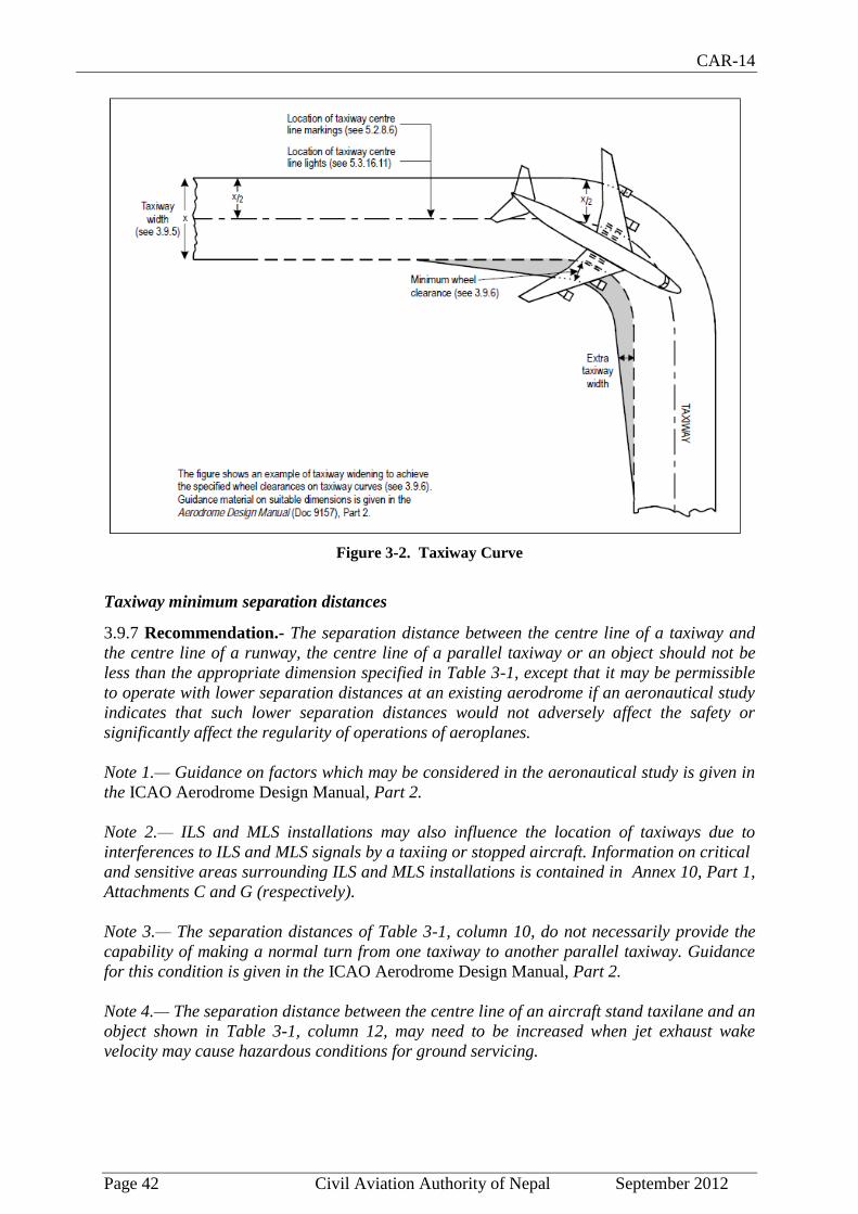
CAR-14
Page 42 Civil Aviation Authority of Nepal September 2012
Figure 3-2. Taxiway Curve
Taxiway minimum separation distances
3.9.7 Recommendation.- The separation distance between the centre line of a taxiway and
the centre line of a runway, the centre line of a parallel taxiway or an object should not be
less than the appropriate dimension specified in Table 3-1, except that it may be permissible
to operate with lower separation distances at an existing aerodrome if an aeronautical study
indicates that such lower separation distances would not adversely affect the safety or
significantly affect the regularity of operations of aeroplanes.
Note 1.— Guidance on factors which may be considered in the aeronautical study is given in
the ICAO Aerodrome Design Manual, Part 2.
Note 2.— ILS and MLS installations may also influence the location of taxiways due to
interferences to ILS and MLS signals by a taxiing or stopped aircraft. Information on critical
and sensitive areas surrounding ILS and MLS installations is contained in Annex 10, Part 1,
Attachments C and G (respectively).
Note 3.— The separation distances of Table 3-1, column 10, do not necessarily provide the
capability of making a normal turn from one taxiway to another parallel taxiway. Guidance
for this condition is given in the ICAO Aerodrome Design Manual, Part 2.
Note 4.— The separation distance between the centre line of an aircraft stand taxilane and an
object shown in Table 3-1, column 12, may need to be increased when jet exhaust wake
velocity may cause hazardous conditions for ground servicing.

CAR-14
Page 43 Civil Aviation Authority of Nepal September 2012
Slopes on taxiways
3.9.8 Longitudinal slopes
Recommendation.- The longitudinal slope of a taxiway should not exceed:
- 1.5 per cent where the code letter is C, D, E or F; and
- 3 per cent where the code letter is A or B.
3.9.9 Longitudinal slope changes
Recommendation.- Where slope changes on a taxiway cannot be avoided, the transition
from one slope to another slope should be accomplished by a curved surface with a rate
of change not exceeding:
- 1 per cent per 30 m (minimum radius of curvature of 3 000 m) where the code
letter is C, D, E or F; and
- 1 per cent per 25 m (minimum radius of curvature of 2 500 m) where the code
letter is A or B.
3.9.10 Sight distance
Recommendation.- Where a change in slope on a taxiway cannot be avoided, the change
should be such that, from any point:
— 3 m above the taxiway, it will be possible to see the whole surface of the taxiway for a
distance of at least 300 m from that point, where the code letter is C, D, E or F;
— 2 m above the taxiway, it will be possible to see the whole surface of the taxiway for a
distance of at least 200 m from that point, where the code letter is B; and
— 1.5 m above the taxiway, it will be possible to see the whole surface of the taxiway for a
distance of at least 150 m from that point, where the code letter is A.

CAR-14
Page 44 Civil Aviation Authority of Nepal September 2012
3.9.11 Transverse slopes
Recommendation.- The transverse slopes of a taxiway should be sufficient to prevent the
accumulation of water on the surface of the taxiway but should not exceed:
- 1.5 per cent where the code letter is C, D, E or F; and
- 2 per cent where the code letter is A or B.
Note.— See 3.13.4 regarding transverse slopes on an aircraft stand taxilane.
Strength of taxiways
3.9.12 Recommendation.- The strength of a taxiway should be at least equal to that of the
runway it serves, due consideration being given to the fact that a taxiway will be subjected to
a greater density of traffic and, as a result of slow moving and stationary aeroplanes, to
higher stresses than the runway it serves.
Note.— Guidance on the relation of the strength of taxiways to the strength of runways is
given in the ICAO Aerodrome Design Manual, Part 3.
Surface of taxiways
3.9.13 Recommendation.- The surface of a taxiway should not have irregularities that cause
damage to aeroplane structures.
3.9.14 Recommendation.- The surface of a paved taxiway should be so constructed as to
provide good friction characteristics when the taxiway is wet.
Rapid exit taxiways
Note: The following specifications detail requirements particular to rapid exit taxiways. See
Figure 3-3. General requirements for taxiways also apply to this type of taxiway. Guidance
on the provision, location and design of rapid exit taxiways is included in the ICAO
Aerodrome Design Manual, Part 2.
3.9.15 Recommendation.- A rapid exit taxiway should be designed with a radius of turn-off
curve of at least:
- 550 m where the code number is 3 or 4; and
- 275 m where the code number is 1 or 2;
to enable exit speeds under wet conditions of:
- 93 km/h where the code number is 3 or 4; and
- 65 km/h where the code number is 1 or 2.
Note.— The locations of rapid exit taxiways along a runway are based on several criteria
described in the ICAO Aerodrome Design Manual, Part 2, in addition to different speed
criteria.

CAR-14
Page 45 Civil Aviation Authority of Nepal September 2012
3.9.16 Recommendation.- The radius of the fillet on the inside of the curve at a rapid exit
taxiway should be sufficient to provide a widened taxiway throat in order to facilitate early
recognition of the entrance and turn-off onto the taxiway.
3.9.17 Recommendation.- A rapid exit taxiway should include a straight distance after the
turn-off curve sufficient for an exiting aircraft to come to a full stop clear of any intersecting
taxiway.
3.9.18 Recommendation.- The intersection angle of a rapid exit taxiway with the runway
should not be greater than 45° nor less than 25° and preferably should be 30°.
Taxiways on bridges
3.9.19 The width of that portion of a taxiway bridge capable of supporting aeroplanes, as
measured perpendicularly to the taxiway centre line, shall not be less than the width of the
graded area of the strip provided for that taxiway, unless a proven method of lateral restraint
is provided which shall not be hazardous for aeroplanes for which the taxiway is intended.
3.9.20 Recommendation.- Access should be provided to allow rescue and fire fighting
vehicles to intervene in both directions within the specified response time to the largest
aeroplane for which the taxiway bridge is intended.
Note.— If aeroplane engines overhang the bridge structure, protection of adjacent areas
below the bridge from engine blast may be required.
3.9.21 Recommendation.- A bridge should be constructed on a straight section of the
taxiway with a straight section on both ends of the bridge to facilitate the alignment of
aeroplanes approaching the bridge.

CAR-14
Page 46 Civil Aviation Authority of Nepal September 2012
3.10 Taxiway shoulders
Note.— Guidance on characteristics of taxiway shoulders and on shoulder treatment is given
in the ICAO Aerodrome Design Manual, Part 2.
3.10.1 Recommendation.- Straight portions of a taxiway where the code letter is C, D, E or
F should be provided with shoulders which extend symmetrically on each side of the taxiway
so that the overall width of the taxiway and its shoulders on straight portions is not less than:
- 60 m where the code letter is F;
- 44 m where the code letter is E;
- 38 m where the code letter is D; and
- 25 m where the code letter is C.
On taxiway curves and on junctions or intersections where increased pavement is provided,
the shoulder width should be not less than that on the adjacent straight portions of the
taxiway.
3.10.2 Recommendation.- When a taxiway is intended to be used by turbine-engined
aeroplanes, the surface of the taxiway shoulder should be so prepared as to resist erosion
and the ingestion of the surface material by aeroplane engines.
3.11 Taxiway strips
Note.— Guidance on characteristics of taxiway strips is given in the ICAO Aerodrome
Design Manual, Part 2.
General
3.11.1 A taxiway, other than an aircraft stand taxilane, shall be included in a strip.
Width of taxiway strips
3.11.2 Recommendation.- A taxiway strip should extend symmetrically on each side of the
centre line of the taxiway throughout the length of the taxiway to at least the distance from
the centre line given in Table 3-1, column 11.
Objects on taxiway strips
Note.— See 9.9 for information regarding siting of equipment and installations on taxiway
strips.
3.11.3 Recommendation.- The taxiway strip should provide an area clear of objects which
may endanger taxiing aeroplanes.
Note.— Consideration will have to be given to the location and design of drains on a taxiway
strip to prevent damage to an aeroplane accidentally running off a taxiway. Suitably
designed drain covers may be required.

CAR-14
Page 47 Civil Aviation Authority of Nepal September 2012
Grading of taxiway strips
3.11.4 Recommendation.- The centre portion of a taxiway strip should provide a graded
area to a distance from the centre line of the taxiway of at least:
- 11 m where the code letter is A;
- 12.5 m where the code letter is B or C;
- 19 m where the code letter is D;
- 22 m where the code letter is E; and
- 30 m where the code letter is F.
Slopes on taxiway strips
3.11.5 Recommendation.- The surface of the strip should be flush at the edge of the taxiway
or shoulder, if provided, and the graded portion should not have an upward transverse slope
exceeding:
- 2.5 per cent for strips where the code letter is C, D, E or F; and
- 3 per cent for strips of taxiways where the code letter is A or B;
the upward slope being measured with reference to the transverse slope of the adjacent
taxiway surface and not the horizontal. The downward transverse slope should not exceed 5
per cent measured with reference to the horizontal.
3.11.6 Recommendation.- The transverse slopes on any portion of a taxiway strip beyond
that to be graded should not exceed an upward or downward slope of 5 per cent as measured
in the direction away from the taxiway.
3.12 Holding bays, runway-holding positions, intermediate holding positions and road-
holding positions
General
3.12.1 Recommendation.- The holding bay(s) should be provided when the traffic density is
medium or heavy.
3.12.2 A runway-holding position or positions shall be established:
a) on the taxiway, at the intersection of a taxiway and a runway; and
b) at an intersection of a runway with another runway when the former runway is
part of a standard taxi-route.
3.12.3 A runway-holding position shall be established on a taxiway if the location or
alignment of the taxiway is such that a taxiing aircraft or vehicle can infringe an obstacle
limitation surface or interfere with the operation of radio navigation aids.
CAR-14
Page 48 Civil Aviation Authority of Nepal September 2012
3.12.4 Recommendation.- An intermediate holding position should be established on a
taxiway at any point other than a runway-holding position where it is desirable to define a
specific holding limit.
3.12.5 A road-holding position shall be established at an intersection of a road with a runway.
Location
3.12.6 The distance between a holding bay, runway holding position established at a
taxiway/runway intersection or road-holding position and the centre line of a runway shall be
in accordance with Table 3-2 and, in the case of a precision approach runway, such that a
holding aircraft or vehicle will not interfere with the operation of radio navigation aids.
3.12.7 Recommendation.- At elevations greater than 700 m (2 300 ft) the distance of 90 m
specified in Table 3-2 for a precision approach runway code number 4 should be increased
as follows:
a) up to an elevation of 2 000 m (6 600 ft); 1 m for every 100 m (330 ft) in excess of 700 m
(2 300 ft);
b) elevation in excess of 2 000 m (6 600 ft) and up to 4 000 m (13 320 ft); 13 m plus 1.5 m for
every 100 m (330 ft) in excess of 2 000 m (6 600 ft); and
c) elevation in excess of 4 000 m (13 320 ft) and up to 5 000 m (16 650 ft); 43 m plus 2 m for
every 100 m (330 ft) in excess of 4 000 m (13 320 ft).
3.12.8 Recommendation.- If a holding bay, runway holding position or road-holding
position for a precision approach runway code number 4 is at a greater elevation compared
to the threshold, the distance of 90 m or 107.5 m, as appropriate, specified in Table 3-2
should be further increased 5 m for every metre the bay or position is higher than the
threshold.
3.12.9 The location of a runway-holding position established in accordance with 3.12.3 shall
be such that a holding aircraft or vehicle will not infringe the obstacle free zone, approach
surface, take-off climb surface or ILS/MLS critical/sensitive area or interfere with the
operation of radio
navigation aids.
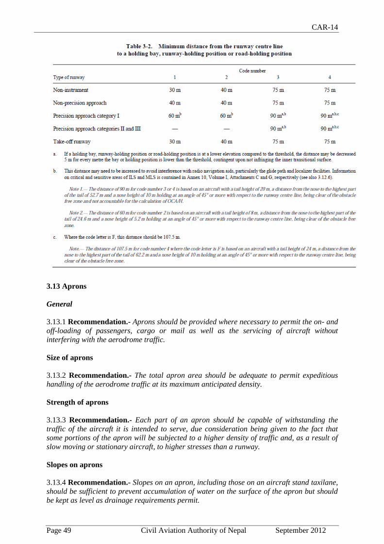
CAR-14
Page 49 Civil Aviation Authority of Nepal September 2012
3.13 Aprons
General
3.13.1 Recommendation.- Aprons should be provided where necessary to permit the on- and
off-loading of passengers, cargo or mail as well as the servicing of aircraft without
interfering with the aerodrome traffic.
Size of aprons
3.13.2 Recommendation.- The total apron area should be adequate to permit expeditious
handling of the aerodrome traffic at its maximum anticipated density.
Strength of aprons
3.13.3 Recommendation.- Each part of an apron should be capable of withstanding the
traffic of the aircraft it is intended to serve, due consideration being given to the fact that
some portions of the apron will be subjected to a higher density of traffic and, as a result of
slow moving or stationary aircraft, to higher stresses than a runway.
Slopes on aprons
3.13.4 Recommendation.- Slopes on an apron, including those on an aircraft stand taxilane,
should be sufficient to prevent accumulation of water on the surface of the apron but should
be kept as level as drainage requirements permit.
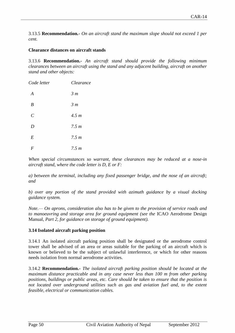
CAR-14
Page 50 Civil Aviation Authority of Nepal September 2012
3.13.5 Recommendation.- On an aircraft stand the maximum slope should not exceed 1 per
cent.
Clearance distances on aircraft stands
3.13.6 Recommendation.- An aircraft stand should provide the following minimum
clearances between an aircraft using the stand and any adjacent building, aircraft on another
stand and other objects:
Code letter Clearance
A 3 m
B 3 m
C 4.5 m
D 7.5 m
E 7.5 m
F 7.5 m
When special circumstances so warrant, these clearances may be reduced at a nose-in
aircraft stand, where the code letter is D, E or F:
a) between the terminal, including any fixed passenger bridge, and the nose of an aircraft;
and
b) over any portion of the stand provided with azimuth guidance by a visual docking
guidance system.
Note.— On aprons, consideration also has to be given to the provision of service roads and
to manoeuvring and storage area for ground equipment (see the ICAO Aerodrome Design
Manual, Part 2, for guidance on storage of ground equipment).
3.14 Isolated aircraft parking position
3.14.1 An isolated aircraft parking position shall be designated or the aerodrome control
tower shall be advised of an area or areas suitable for the parking of an aircraft which is
known or believed to be the subject of unlawful interference, or which for other reasons
needs isolation from normal aerodrome activities.
3.14.2 Recommendation.- The isolated aircraft parking position should be located at the
maximum distance practicable and in any case never less than 100 m from other parking
positions, buildings or public areas, etc. Care should be taken to ensure that the position is
not located over underground utilities such as gas and aviation fuel and, to the extent
feasible, electrical or communication cables.

CAR-14
Page 51 Civil Aviation Authority of Nepal September 2012
3.15 De-icing/anti-icing facilities
Note.— Safe and efficient aeroplane operations are of primary importance in the
development of an aeroplane deicing/anti-icing facility. For further guidance, see the ICAO
Manual on Aircraft Ground De-icing/Anti-icing Operations (Doc 9640).
GGeenneerraall
3.15.1 Recommendation.— Aeroplane de-icing/anti-icing facilities should be provided at an
aerodrome where icing conditions are expected to occur.
LLooccaattiioonn
3.15.2 Recommendation.— De-icing/anti-icing facilities should be provided either at
aircraft stands or at specified remote areas along the taxiway leading to the runway meant
for take-off, provided that adequate drainage arrangements for the collection and safe
disposal of excess de-icing/anti-icing fluids are available to prevent ground water
contamination. The effect of volume of traffic and departure flow rates should also be
considered.
Note 1.— One of the primary factors influencing the location of a de-icing/anti-icing
facility is to ensure that the holdover time of the anti-icing treatment is still in effect at the
end of taxiing and when take-off clearance of the treated aeroplane is given.
Note 2.— Remote facilities compensate for changing weather conditions when icing
conditions or blowing snow are expected to occur along the taxi route taken by the aeroplane
to the runway meant for take-off.
3.15.3 Recommendation.— The remote de-icing/anti-icing facility should be located to be
clear of the obstacle limitation surfaces specified in Chapter 4, not cause interference to the
radio navigation aids and be clearly visible from the air traffic control tower for clearing the
treated aeroplane.
3.15.4 Recommendation.— The remote de-icing/anti-icing facility should be so located as to
provide for an expeditious traffic flow, perhaps with a bypass configuration, and not require
unusual taxiing manoeuvre into and out of the pads.
Note. — The jet blast effects caused by a moving aeroplane on other aeroplanes receiving
the anti-icing treatment or taxiing behind will have to be taken into account to prevent
degradation of the treatment.
SSiizzee aanndd nnuummbbeerr ooff ddee--iicciinngg//aannttii--iicciinngg ppaaddss
Note.— An aeroplane de-icing/anti-icing pad consists of a) an inner area for parking of an
aeroplane to be treated, and b) an outer area for movement of two or more mobile de-icing/
anti-icing equipment.
3.15.5 Recommendation.— The size of a de-icing/anti-icing pad should be equal to the
parking area required by the most demanding aeroplane in a given category with at least 3.8
m clear paved area all round the aeroplane for the movement of the de-icing/anti-icing
vehicles.
Note.— Where more than one de-icing/anti-icing pad is provided, consideration will have
to be given to providing deicing/anti-icing vehicle movement areas of adjacent pads that do
not overlap, but are exclusive for each pad. Consideration will also need to be given to
bypassing of the area by other aeroplanes with the clearances specified in 3.15.9 and
3.15.10.
3.15.6 Recommendation.— The number of de-icing/anti-icing pads required should be
determined based on the meteorological conditions, the type of aeroplanes to be treated, the

CAR-14
Page 52 Civil Aviation Authority of Nepal September 2012
method of application of de-icing/anti-icing fluid, the type and capacity of the dispensing
equipment used, and the departure flow rates.
Note.— See the ICAO Aerodrome Design Manual, Part 2.
Slopes on de-icing/anti-icing pads
3.15.7 Recommendation.— The de-icing/anti-icing pads should be provided with suitable
slopes to ensure satisfactory drainage of the area and to permit collection of all excess de-
icing/anti-icing fluid running off an aeroplane. The maximum longitudinal slope should be as
little as practicable and the transverse slope should not exceed 1 per cent.
SSttrreennggtthh ooff ddee--iicciinngg//aannttii--iicciinngg ppaaddss
3.15.8 Recommendation.— The de-icing/anti-icing pad should be capable of withstanding
the traffic of the aircraft it is intended to serve, due consideration being given to the fact that
the de-icing/anti-icing pad (like an apron) will be subjected to a higher density of traffic and,
as a result of slow-moving or stationary aircraft, to higher stresses than a runway.
CClleeaarraannccee ddiissttaanncceess oonn aa ddee--iicciinngg//aannttii--iicciinngg ppaadd
3.15.9 Recommendation.— A de-icing/anti-icing pad should provide the minimum
clearances specified in 3.13.6 for aircraft stands. If the pad layout is such as to include
bypass configuration, the minimum separation distances specified in Table 3-1, column 12,
should be provided.
3.15.10 Recommendation.— Where the de-icing/anti-icing facility is located adjoining a
regular taxiway, the taxiway minimum separation distance specified in Table 3-1, column
11, should be provided. (See Figure 3-4.)
EEnnvviirroonnmmeennttaall ccoonnssiiddeerraattiioonnss
Note.— The excess de-icing/anti-icing fluid running off an aeroplane poses the risk of
contamination of ground water in addition to affecting the pavement surface friction
characteristics.
3.15.11 Recommendation.— Where de-icing/anti-icing activities are carried out, the
surface drainage should be planned to collect the run-off separately, preventing its mixing
with the normal surface run-off so that it does not pollute the ground
water.

CAR-14
Page 53 Civil Aviation Authority of Nepal September 2012
CHAPTER -4
OBSTACLE RESTRICTION AND REMOVAL
Note 1.— The objectives of the specifications in this chapter are to define the airspace
around aerodromes to be maintained free from obstacles so as to permit the intended
aeroplane operations at the aerodromes to be conducted safely and to prevent the
aerodromes from becoming unusable by the growth of obstacles around the aerodromes. This
is achieved by establishing a series of obstacle limitation surfaces that define the limits to
which objects may project into the airspace.
Note 2.— Objects which penetrate the obstacle limitation surfaces contained in this chapter
may in certain circumstances cause an increase in the obstacle clearance altitude/height for
an instrument approach procedure or any associated visual circling procedure or have other
operational impact on flight procedure design. Criteria for flight procedure design are
contained in ICAO Procedures for Air Navigation Services – Aircraft Operations (PANS-
OPS, Doc 8168).
Note 3.— The establishment of, and requirements for, an obstacle protection surface for
visual approach slope indicator systems are specified in 5.3.5.41 to 5.3.5.45.
4.1 Obstacle limitation surfaces
Note.— See Figure 4-1.
Outer horizontal surface
Note.— Guidance on the need to provide an outer horizontal surface and its characteristics
is contained in the ICAO Airport Services Manual (Doc 9137), Part 6.
Conical surface
4.1.1 Description.— Conical surface. A surface sloping upwards and outwards from the
periphery of the inner horizontal surface.
4.1.2 Characteristics.— The limits of the conical surface shall comprise:
a) a lower edge coincident with the periphery of the inner horizontal surface; and
b) an upper edge located at a specified height above the inner horizontal surface.
4.1.3 The slope of the conical surface shall be measured in a vertical plane perpendicular to
the periphery of the inner horizontal surface.
Inner horizontal surface
4.1.4 Description.— Inner horizontal surface. A surface located in a horizontal plane above
an aerodrome and its environs.
4.1.5 Characteristics.— The radius or outer limits of the inner horizontal surface shall be
measured from a reference point or points established for such purpose.

CAR-14
Page 54 Civil Aviation Authority of Nepal September 2012
Note.— The shape of the inner horizontal surface need not necessarily be circular. Guidance
on determining the extent of the inner horizontal surface is contained in the ICAO Airport
Services Manual (Doc 9137), Part 6.
4.1.6 The height of the inner horizontal surface shall be measured above an elevation datum
established for such purpose.
Note.— Guidance on determining the elevation datum is contained in the ICAO Airport
Services Manual (Doc 9137), Part 6.
Approach surface
4.1.7 Description — Approach surface. An inclined plane or combination of planes
preceding the threshold.
4.1.8 Characteristics.— The limits of the approach surface shall comprise:
a) an inner edge of specified length, horizontal and perpendicular to the extended
centre line of the runway and located at a specified distance before the threshold;
b) two sides originating at the ends of the inner edge and diverging uniformly at a
specified rate from the extended centre line of the runway;
c) an outer edge parallel to the inner edge; and
d) The above surfaces shall be varied when lateral offset, offset or curved approaches
are utilized, specifically, two sides originating at the ends of the inner edge and
diverging uniformly at a specified rate from the extended centre line of the lateral
offset, offset or curved ground track.
4.1.9 The elevation of the inner edge shall be equal to the elevation of the mid-point of the
threshold.
4.1.10 The slope(s) of the approach surface shall be measured in the vertical plane containing
the centre line of the runway and shall continue containing the centre line of any lateral offset
or curved ground track.
Inner approach surface
4.1.11 Description.— Inner approach surface. A rectangular portion of the approach surface
immediately preceding the threshold.
4.1.12 Characteristics.— The limits of the inner approach surface shall comprise:
a) an inner edge coincident with the location of the inner edge of the approach surface
but of its own specified length;
b) two sides originating at the ends of the inner edge and extending parallel to the
vertical plane containing the centre line of the runway; and
c) an outer edge parallel to the inner edge.

CAR-14
Page 55 Civil Aviation Authority of Nepal September 2012
Transitional surface
4.1.13 Description.— Transitional surface. A complex surface along the side of the strip and
part of the side of the approach surface, that slopes upwards and outwards to the inner
horizontal surface.
4.1.14 Characteristics.— The limits of a transitional surface shall comprise:
a) a lower edge beginning at the intersection of the side of the approach surface with the inner
horizontal surface and extending down the side of the approach surface to the inner edge of
the approach surface and from there along the length of the strip parallel to the runway centre
line; and
b) an upper edge located in the plane of the inner horizontal surface.
4.1.15 The elevation of a point on the lower edge shall be:
a) along the side of the approach surface — equal to the elevation of the approach
surface at that point; and
b) along the strip — equal to the elevation of the nearest point on the centre line of
the runway or its extension.
Note.— As a result of b) the transitional surface along the strip will be curved if the runway
profile is curved, or a plane if the runway profile is a straight line. The intersection of the
transitional surface with the inner horizontal surface will also be a curved or a straight line
depending on the runway profile.
4.1.16 The slope of the transitional surface shall be measured in a vertical plane at right
angles to the centre line of the runway.
Inner transitional surface
Note.— It is intended that the inner transitional surface be the controlling obstacle limitation
surface for navigation aids, aircraft and other vehicles that must be near the runway and
which is not to be penetrated except for frangible objects. The transitional surface described
in 4.1.13 is intended to remain as the controlling obstacle limitation surface for buildings,
etc.
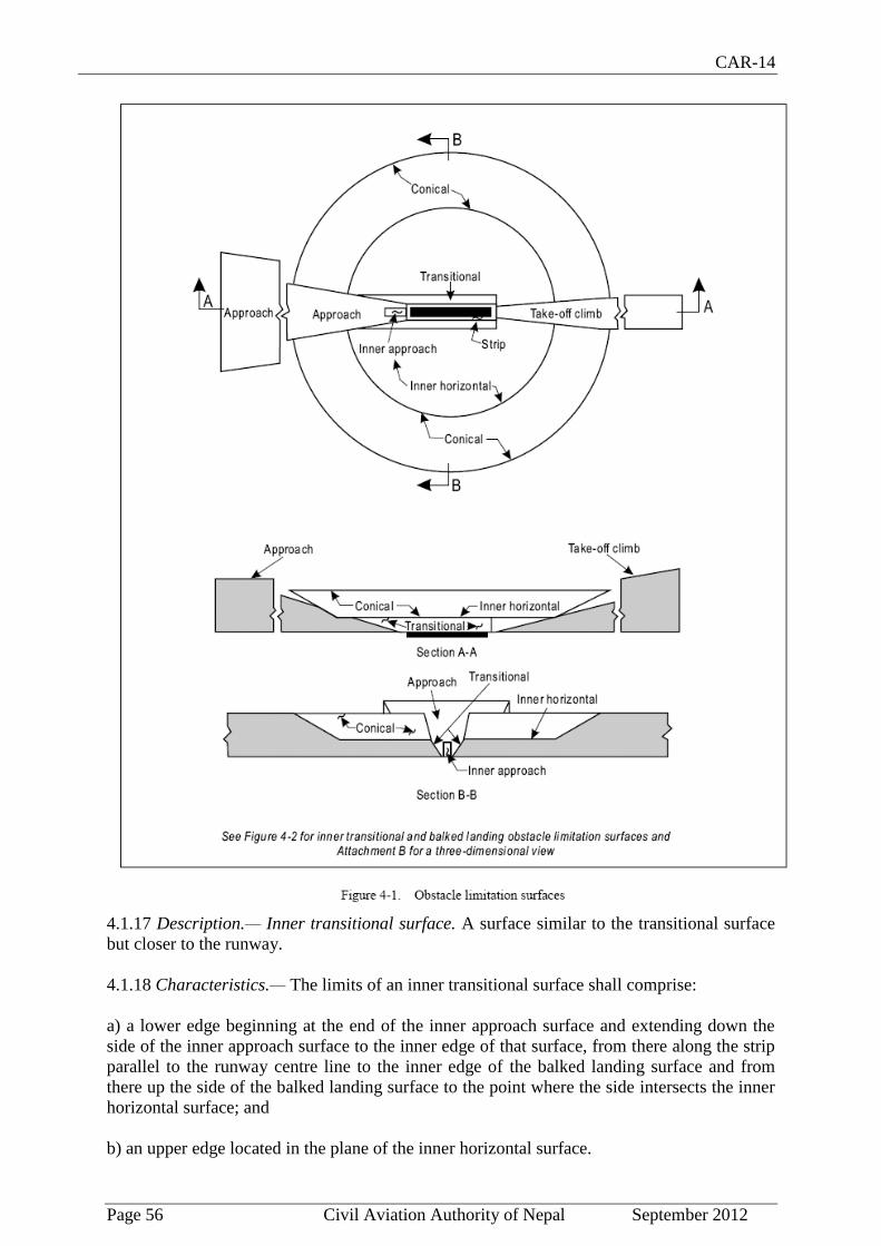
CAR-14
Page 56 Civil Aviation Authority of Nepal September 2012
4.1.17 Description.— Inner transitional surface. A surface similar to the transitional surface
but closer to the runway.
4.1.18 Characteristics.— The limits of an inner transitional surface shall comprise:
a) a lower edge beginning at the end of the inner approach surface and extending down the
side of the inner approach surface to the inner edge of that surface, from there along the strip
parallel to the runway centre line to the inner edge of the balked landing surface and from
there up the side of the balked landing surface to the point where the side intersects the inner
horizontal surface; and
b) an upper edge located in the plane of the inner horizontal surface.

CAR-14
Page 57 Civil Aviation Authority of Nepal September 2012
4.1.19 The elevation of a point on the lower edge shall be:
a) along the side of the inner approach surface and balked landing surface — equal to the
elevation of the particular surface at that point; and
b) along the strip — equal to the elevation of the nearest point on the centre line of the
runway or its extension.
Note.— As a result of b) the inner transitional surface along the strip will be curved if the
runway profile is curved or a plane if the runway profile is a straight line. The intersection of
the inner transitional surface with the inner horizontal surface will also be a curved or
straight line depending on the runway profile.
4.1.20 The slope of the inner transitional surface shall be measured in a vertical plane at right
angles to the centre line of the runway.
Balked landing surface
4.1.21 Description.— Balked landing surface. An inclined plane located at a specified
distance after the threshold, extending between the inner transitional surface.
4.1.22 Characteristics.— The limits of the balked landing surface shall comprise:
a) an inner edge horizontal and perpendicular to the centre line of the runway and located at a
specified distance after the threshold;
b) two sides originating at the ends of the inner edge and diverging uniformly at a specified
rate from the vertical plane containing the centre line of the runway; and
c) an outer edge parallel to the inner edge and located in the plane of the inner horizontal
surface.
4.1.23 The elevation of the inner edge shall be equal to the elevation of the runway centre
line at the location of the inner edge.
4.1.24 The slope of the balked landing surface shall be measured in the vertical plane
containing the centre line of the runway.

CAR-14
Page 58 Civil Aviation Authority of Nepal September 2012
Take-off climb surface
4.1.25 Description.— Take-off climb surface. An inclined plane or other specified surface
beyond the end of a runway or clearway.
4.1.26 Characteristics.— The limits of the take-off climb surface shall comprise:
a) an inner edge horizontal and perpendicular to the centre line of the runway and located
either at a specified distance beyond the end of the runway or at the end of the clearway when
such is provided and its length exceeds the specified distance;
b) two sides originating at the ends of the inner edge, diverging uniformly at a specified rate
from the take-off track to a specified final width and continuing thereafter at that width for
the remainder of the length of the takeoff climb surface; and
c) an outer edge horizontal and perpendicular to the specified take-off track.
4.1.27 The elevation of the inner edge shall be equal to the highest point on the extended
runway centre line between the end of the runway and the inner edge, except that when a
clearway is provided the elevation shall be equal to the highest point on the ground on the
centre line of the clearway.

CAR-14
Page 59 Civil Aviation Authority of Nepal September 2012
4.1.28 In the case of a straight take-off flight path, the slope of the take-off climb surface
shall be measured in the vertical plane containing the centre line of the runway.
4.1.29 In the case of a take-off flight path involving a turn, the take-off climb surface shall be
a complex surface containing the horizontal normals to its centre line, and the slope of the
centre line shall be the same as that for a straight take-off flight path.
4.2 Obstacle limitation requirements
Note.— The requirements for obstacle limitation surfaces are specified on the basis of the
intended use of a runway, i.e. take-off or landing and type of approach, and are intended to
be applied when such use is made of the runway. In cases where operations are conducted to
or from both directions of a runway, then the function of certain surfaces may be nullified
because of more stringent requirements of another lower surface.
Non-instrument runways
4.2.1 The following obstacle limitation surfaces shall be established for a non-instrument
runway:
- conical surface;
- inner horizontal surface;
- approach surface; and
- transitional surfaces.
4.2.2 The heights and slopes of the surfaces shall not be greater than, and their other
dimensions not less than, those specified in Table 4-1.
4.2.3 New objects or extensions of existing objects shall not be permitted above an approach
or transitional surface except when, in the opinion of the Director General of Civil Aviation
Authority of Nepal, the new object or extension would be shielded by an existing immovable
object.
Note.— Circumstances in which the shielding principle may reasonably be applied are
described in the ICAO Airport Services Manual (Doc 9137), Part 6.
4.2.4 New objects or extensions of existing objects shall not be permitted above the conical
surface or inner horizontal surface except when, in the opinion of the Director General of
Civil Aviation Authority of Nepal, the object would be shielded by an existing immovable
object, or after aeronautical study it is determined that the object would not adversely affect
the safety or significantly affect the regularity of operations of aeroplanes.
4.2.5 Recommendation.- Existing objects above any of the surfaces required by 4.2.1 should
as far as practicable be removed except when, in the opinion of the Director General of Civil
Aviation Authority of Nepal, the object is shielded by an existing immovable object, or after
aeronautical study it is determined that the object would not adversely affect the safety or
significantly affect the regularity of operations of aeroplanes.
Note.— Because of transverse or longitudinal slopes on a strip, in certain cases the inner
edge or portions of the inner edge of the approach surface may be below the corresponding
elevation of the strip. It is not intended that the strip be graded to conform with the inner
edge of the approach surface, nor is it intended that terrain or objects which are above the

CAR-14
Page 60 Civil Aviation Authority of Nepal September 2012
approach surface beyond the end of the strip, but below the level of the strip, be removed
unless it is considered they may endanger aeroplanes.
4.2.6 Recommendation.- In considering proposed construction, account should be taken of
the possible future development of an instrument runway and consequent requirement for
more stringent obstacle limitation surfaces.
Non-precision approach runways
4.2.7 The following obstacle limitation surfaces shall be established for a non-precision
approach runway:
- conical surface;
- inner horizontal surface;
- approach surface; and
- transitional surfaces.
4.2.8 The heights and slopes of the surfaces shall not be greater than, and their other
dimensions not less than, those specified in Table 4-1, except in the case of the horizontal
section of the approach surface (see 4.2.9).
4.2.9 The approach surface shall be horizontal beyond the point at which the 2.5 per cent
slope intersects:
a) a horizontal plane 150 m above the threshold elevation; or
b) the horizontal plane passing through the top of any object that governs the obstacle
clearance altitude/height (OCA/H);
whichever is the higher.
4.2.10 New objects or extensions of existing objects shall not be permitted above an approach
surface within 3 000 m of the inner edge or above a transitional surface except when, in the
opinion of the Director General of Civil Aviation Authority of Nepal, the new object or
extension would be shielded by an existing immovable object.
Note.— Circumstances in which the shielding principle may reasonably be applied are
described in the ICAO Airport Services Manual, Part 6.
4.2.11 New objects or extensions of existing objects shall not be permitted above the
approach surface beyond 3 000 m from the inner edge, the conical surface or inner horizontal
surface except when, in the opinion of the Director General of Civil Aviation Authority of
Nepal, the object would be shielded by an existing immovable object, or after aeronautical
study it is determined that the object would not adversely affect the safety or significantly
affect the regularity of operations of aeroplanes.
4.2.12 Recommendation.- The existing objects above any of the surfaces required by 4.2.7
should as far as practicable be removed except when, in the opinion of the Director General
of Civil Aviation authority of Nepal, the object is shielded by an existing immovable object,
or after aeronautical study it is determined that the object would not adversely affect the
safety or significantly affect the regularity of operations of aeroplanes.

CAR-14
Page 61 Civil Aviation Authority of Nepal September 2012
Note.— Because of transverse or longitudinal slopes on a strip, in certain cases the inner
edge or portions of the inner edge of the approach surface may be below the corresponding
elevation of the strip. It is not intended that the strip be graded to conform with the inner
edge of the approach surface, nor is it intended that terrain or objects which are above the
approach surface beyond the end of the strip, but below the level of the strip, be removed
unless it is considered they may endanger aeroplanes.
Precision approach runways
Note 1.— See 9.9 for information regarding siting of equipment and installations on
operational areas.
Note 2.— Guidance on obstacle limitation surfaces for precision approach runways is given
in the ICAO Airport Services Manual, Part 6.
4.2.13 The following obstacle limitation surfaces shall be established for a precision approach
runway category I:
- conical surface;
- inner horizontal surface;
- approach surface; and
- transitional surfaces.
4.2.14 Recommendation.- The following obstacle limitation surfaces should be established
for a precision approach runway category I:
- inner approach surface;
- inner transitional surfaces; and
- balked landing surface.
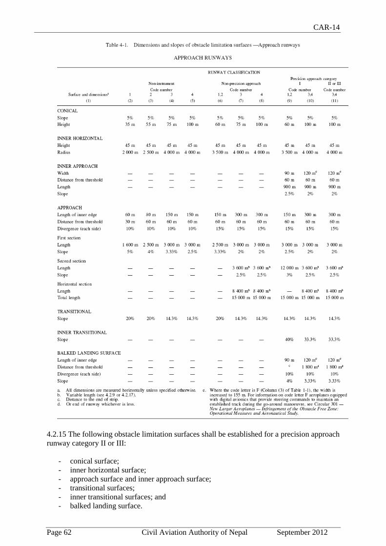
CAR-14
Page 62 Civil Aviation Authority of Nepal September 2012
4.2.15 The following obstacle limitation surfaces shall be established for a precision approach
runway category II or III:
- conical surface;
- inner horizontal surface;
- approach surface and inner approach surface;
- transitional surfaces;
- inner transitional surfaces; and
- balked landing surface.

CAR-14
Page 63 Civil Aviation Authority of Nepal September 2012
4.2.16 The heights and slopes of the surfaces shall not be greater than, and their other
dimensions not less than, those specified in Table 4-1, except in the case of the horizontal
section of the approach surface (see 4.2.17).
4.2.17 The approach surface shall be horizontal beyond the point at which the 2.5 per cent
slope intersects:
a) a horizontal plane 150 m above the threshold elevation; or
b) the horizontal plane passing through the top of any object that governs the obstacle
clearance limit;
whichever is the higher.
4.2.18 Fixed objects shall not be permitted above the inner approach surface, the inner
transitional surface or the balked landing surface, except for frangible objects which because
of their function must be located on the strip. Mobile objects shall not be permitted above
these surfaces during the use of the runway for landing.
4.2.19 New objects or extensions of existing objects shall not be permitted above an approach
surface or a transitional surface except when, in the opinion of the Director General of Civil
Aviation Authority of Nepal, the new object or extension would be shielded by an existing
immovable object.
Note.— Circumstances in which the shielding principle may reasonably be applied are
described in the Airport Services Manual, Part 6.
4.2.20 New objects or extensions of existing objects shall not be permitted above the conical
surface and the inner horizontal surface except when, in the opinion of the Director General
of Civil Aviation Authority of Nepal, an object would be shielded by an existing immovable
object, or after aeronautical study it is determined that the object would not adversely affect
the safety or significantly affect the regularity of operations of aeroplanes.
4.2.21 Recommendation.- Existing objects above an approach surface, a transitional
surface, the conical surface and inner horizontal surface should as far as practicable be
removed except when, in the opinion of the Director General of Civil Aviation Authority of
Nepal, an object is shielded by an existing immovable object, or after aeronautical study it is
determined that the object would not adversely affect the safety or significantly affect the
regularity of operations of aeroplanes.
Note.— Because of transverse or longitudinal slopes on a strip, in certain cases the inner
edge or portions of the inner edge of the approach surface may be below the corresponding
elevation of the strip. It is not intended that the strip be graded to conform with the inner
edge of the approach surface, nor is it intended that terrain or objects which are above the
approach surface beyond the end of the strip, but below the level of the strip, be removed
unless it is considered they may endanger aeroplanes.
Runways meant for take-off
4.2.22 The following obstacle limitation surface shall be established for a runway meant for
take-off:
- take-off climb surface.

CAR-14
Page 64 Civil Aviation Authority of Nepal September 2012
4.2.23 The dimensions of the surface shall be not less than the dimensions specified in Table
4-2, except that a lesser length may be adopted for the take-off climb surface where such
lesser length would be consistent with procedural measures adopted to govern the outward
flight of aeroplanes.
4.2.24 Recommendation.- The operational characteristics of aeroplanes for which the
runway is intended should be examined to see if it is desirable to reduce the slope specified in
Table 4-2 when critical operating conditions are to be catered to. If the specified slope is
reduced, corresponding adjustment in the length of take-off climb surface should be made so
as to provide protection to a height of 300 m.
Note.— When local conditions differ widely from sea level standard atmospheric conditions,
it may be advisable for the slope specified in Table 4-2 to be reduced. The degree of this
reduction depends on the divergence between local conditions and sea level standard
atmospheric conditions, and on the performance characteristics and operational
requirements of the aeroplanes for which the runway is intended.
4.2.25 New objects or extensions of existing objects shall not be permitted above a take-off
climb surface except when, in the opinion of the Director General of Civil Aviation Authority
of Nepal, the new object or extension would be shielded by an existing immovable object.
Note.— Circumstances in which the shielding principle may reasonably be applied are
described in the ICAO Airport Services Manual, Part 6.
4.2.26 Recommendation.- If no object reaches the 2 per cent (1:50) take-off climb surface,
new objects should be limited to preserve the existing obstacle free surface or a surface down
to a slope of 1.6 per cent (1:62.5).
4.2.27 Recommendation.- Existing objects that extend above a take-off climb surface should
as far as practicable be removed except when, in the opinion of the Director General of Civil
Aviation Authority of Nepal, an object is shielded by an existing immovable object, or after
aeronautical study it is determined that the object would not adversely affect the safety or
significantly affect the regularity of operations of aeroplanes.
Note.— Because of transverse slopes on a strip or clearway, in certain cases portions of the
inner edge of the take-off climb surface may be below the corresponding elevation of the strip
or clearway. It is not intended that the strip or clearway be graded to conform with the inner
edge of the take-off climb surface, nor is it intended that terrain or objects which are above
the take-off climb surface beyond the end of the strip or clearway, but below the level of the
strip or clearway, be removed unless it is considered they may endanger aeroplanes. Similar
considerations apply at the junction of a clearway and strip where differences in transverse
slopes exist.

CAR-14
Page 65 Civil Aviation Authority of Nepal September 2012
4.3 Objects outside the obstacle limitation surfaces
4.3.1 Recommendation.- Arrangements should be made to enable the Director General of
Civil Aviation Authority of Nepal to be consulted concerning proposed construction beyond
the limits of the obstacle limitation surfaces that extend above a height established by that
authority, in order to permit an aeronautical study of the effect of such construction on the
operation of aeroplanes.
4.3.2 Recommendation.- In areas beyond the limits of the obstacle limitation surfaces, at
least those objects which extend to a height of 150 m or more above ground elevation should
be regarded as obstacles, unless a special aeronautical study indicates that they do not
constitute a hazard to aeroplanes.
Note.— This study may have regard to the nature of operations concerned and may
distinguish between day and night operations.
4.4 Other objects
4.4.1 Recommendation.- The objects which do not project through the approach surface but
which would nevertheless adversely affect the optimum siting or performance of visual or
non-visual aids should, as far as practicable, be removed.
4.4.2 Recommendation.- Anything which may, in the opinion of the Director General of
Civil Aviation Authority of Nepal after aeronautical study, endanger aeroplanes on the
movement area or in the air within the limits of the inner horizontal and conical surfaces
shall be regarded as an obstacle and should be removed in so far as practicable.
Note.— In certain circumstances, objects that do not project above any of the surfaces
enumerated in 4.1 may constitute a hazard to aeroplanes as, for example, where there are
one or more isolated objects in the vicinity of an aerodrome.

CAR-14
Page 66 Civil Aviation Authority of Nepal September 2012
CHAPTER -5
VISUAL AIDS FOR NAVIGATION
5.1 Indicators and signalling devices
5.1.1 Wind direction indicators
Application
5.1.1.1 An aerodrome shall be equipped with at least one wind direction indicator.
Location
5.1.1.2 A wind direction indicator shall be located so as to be visible from aircraft in flight or
on the movement area and in such a way as to be free from the effects of air disturbances
caused by nearby objects.
Characteristics
5.1.1.3 The wind direction indicator shall be in the form of a truncated cone made of fabric and
should have a length of not less than 3.6 m and a diameter, at the larger end, of not less than
0.9 m. It shall be constructed so that it gives a clear indication of the direction of the surface
wind and a general indication of the wind speed. The colour or colours shall be so selected as
to make the wind direction indicator clearly visible and understandable from a height of at least
300 m, having regard to background. Where practicable, a single colour, preferably white or
orange, shall be used. Where a combination of two colours is required to give adequate
conspicuity against changing backgrounds, they shall preferably be orange and white, red and
white, or black and white, and shall be arranged in five alternate bands, the first and last bands
being the darker colour.
5.1.1.4 Recommendation.- The location of at least one wind direction indicator should be
marked by a circular band 15 m in diameter and 1.2 m wide. The band should be centred about
the wind direction indicator support and should be in a colour chosen to give adequate
conspicuity, preferably white.
5.1.1.5 Recommendation.- Provision should be made for illuminating at least one wind
indicator at an aerodrome intended for use at night.
5.1.2 Landing direction indicator
Location
5.1.2.1 Where provided, a landing direction indicator shall be located in a conspicuous place
on the aerodrome.
Characteristics
5.1.2.2 The landing direction indicator shall be in the form of a “T”.
5.1.2.3 The shape and minimum dimensions of a landing “T” shall be as shown in Figure 5-1.
The colour of the landing “T” shall be either white or orange, the choice being dependent on

CAR-14
Page 67 Civil Aviation Authority of Nepal September 2012
the colour that contrasts best with the background against which the indicator will be viewed.
Where
required for use at night the landing “T” shall either be illuminated or outlined by white lights.
5.1.3 Signalling lamp
Application
5.1.3.1 A signalling lamp shall be provided at a controlled aerodrome in the aerodrome control
tower.
Characteristics
5.1.3.2 Recommendation.- A signalling lamp should be capable of producing red, green and
white signals, and of:
a) being aimed manually at any target as required;
b) giving a signal in any one colour followed by a signal in either of the two other
colours; and
c) transmitting a message in any one of the three colours by Morse Code up to a speed
of at least four words per minute.
When selecting the green light, use should be made of the restricted boundary of green as
specified in Appendix 1, 2.1.2.
5.1.3.3 Recommendation.- The beam spread should be not less than 1° nor greater than 3°,
with negligible light beyond 3°. When the signalling lamp is intended for use in the daytime the
intensity of the coloured light should be not less than 6 000 cd.
5.1.4 Signal panels and signal area
Note.— The inclusion of detailed specifications for a signal area in this section is not intended
to imply that one has to be provided. Attachment A, Section 16 provides guidance on the need
to provide ground signals. Annex 2, Appendix 1 specifies the shape, colour and use of visual
ground signals. The Aerodrome Design Manual (Doc 9157), Part 4 provides guidance on their
design.
Location of signal area

CAR-14
Page 68 Civil Aviation Authority of Nepal September 2012
5.1.4.1 Recommendation.- The signal area should be located so as to be visible for all angles
of azimuth above an angle of 10° above the horizontal when viewed from a height of 300 m.
Characteristics of signal area
5.1.4.2 The signal area shall be an even horizontal surface at least 9 m square.
5.1.4.3 Recommendation.- The colour of the signal area should be chosen to contrast with the
colours of the signal panels used, and it shall be surrounded by a white border not less than
0.3 m wide.
5.2 Markings
5.2.1 General
Interruption of runway markings
5.2.1.1 At an intersection of two (or more) runways the markings of the more important
runway, except for the runway side stripe marking, shall be displayed and the markings of the
other runway(s) shall be interrupted. The runway side stripe marking of the more important
runway may be either continued across the intersection or interrupted.
5.2.1.2 The order of importance of runways for the display of runway markings shall be as
follows:
1st - precision approach runway;
2nd
- non-precision approach runway; and
3rd
- non-instrument runway.
5.2.1.3 At an intersection of a runway and taxiway the markings of the runway shall be
displayed and the markings of the taxiway interrupted, except that runway side stripe markings
may be interrupted.
Note.— See 5.2.8.5 regarding the manner of connecting runway and taxiway centre line
markings.
Colour and conspicuity
5.2.1.4 Runway markings shall be white.
Note 1.— It has been found that, on runway surfaces of light colour, the conspicuity of white
markings can be improved by outlining them in black.
Note 2.— It is preferable that the risk of uneven friction characteristics on markings be
reduced in so far as practicable by the use of a suitable kind of paint.
Note 3.— Markings may consist of solid areas or a series of longitudinal stripes providing an
effect equivalent to the solid areas.
5.2.1.5 Taxiway markings, runway turn pad markings and aircraft stand markings shall be
yellow.
5.2.1.6 Apron safety lines shall be of a conspicuous colour which shall contrast with that used
for aircraft stand markings.

CAR-14
Page 69 Civil Aviation Authority of Nepal September 2012
5.2.1.7 Recommendation.- At aerodromes where operations take place at night, pavement
markings should be made with reflective materials designed to enhance the visibility of the
markings.
Note.— Guidance on reflective materials is given in the ICAO Aerodrome Design Manual
(Doc 9157), Part 4.
5.2.1.8 Recommendation.- An unpaved taxiway should be provided, so far as practicable,
with the markings prescribed for paved taxiways.
5.2.2 Runway designation marking
Application
5.2.2.1 A runway designation marking shall be provided at the thresholds of a paved runway.
5.2.2.2 Recommendation.- A runway designation marking should be provided, so far as
practicable, at the thresholds of an unpaved runway.
Location
5.2.2.3 A runway designation marking shall be located at a threshold as shown in Figure 5-2 as
appropriate.
Note.— If the runway threshold is displaced from the extremity of the runway, a sign showing
the designation of the runway may be provided for aeroplanes taking off.
Characteristics
5.2.2.4 A runway designation marking shall consist of a two-digit number and on parallel
runways shall be supplemented with a letter. On a single runway, dual parallel runways and
triple parallel runways the two-digit number shall be the whole number nearest the one-tenth of
the magnetic North when viewed from the direction of approach. On four or more parallel
runways, one set of adjacent runways shall be numbered to the nearest one-tenth magnetic
azimuth and the other set of adjacent runways numbered to the next nearest one-tenth of the
magnetic azimuth. When the above rule would give a single digit number, it shall be preceded
by a zero.
5.2.2.5 In the case of parallel runways, each runway designation number shall be supplemented
by a letter as follows, in the order shown from left to right when viewed from the direction of
approach:
- for two parallel runways: “L” “R”;
- for three parallel runways: “L” “C” “R”;
- for four parallel runways: “L” “R” “L” “R”;
- for five parallel runways: “L” “C” “R” “L” “R” or “L” “R” “L” “C” “R”; and
- for six parallel runways: “L” “C” “R” “L” “C” “R”.
5.2.2.6 The numbers and letters shall be in the form and proportion shown in Figure 5-3. The
dimensions shall be not less than those shown in Figure 5-3.
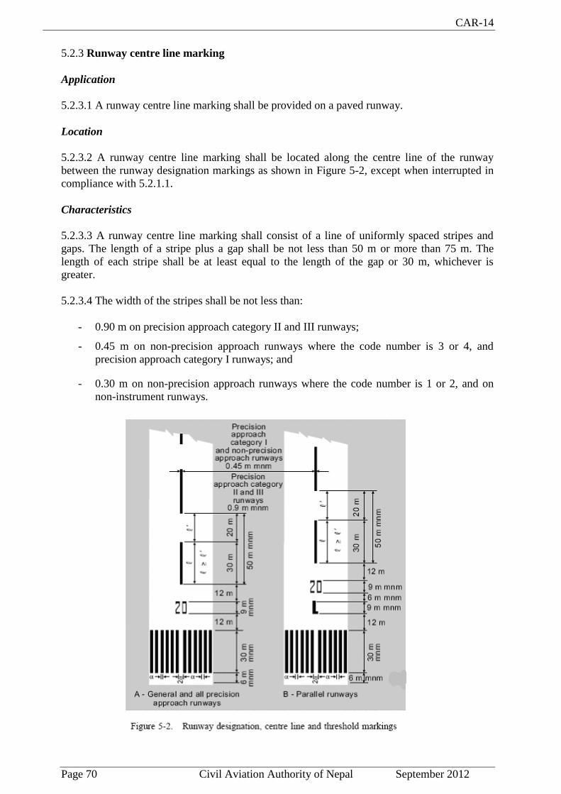
CAR-14
Page 70 Civil Aviation Authority of Nepal September 2012
5.2.3 Runway centre line marking
Application
5.2.3.1 A runway centre line marking shall be provided on a paved runway.
Location
5.2.3.2 A runway centre line marking shall be located along the centre line of the runway
between the runway designation markings as shown in Figure 5-2, except when interrupted in
compliance with 5.2.1.1.
Characteristics
5.2.3.3 A runway centre line marking shall consist of a line of uniformly spaced stripes and
gaps. The length of a stripe plus a gap shall be not less than 50 m or more than 75 m. The
length of each stripe shall be at least equal to the length of the gap or 30 m, whichever is
greater.
5.2.3.4 The width of the stripes shall be not less than:
- 0.90 m on precision approach category II and III runways;
- 0.45 m on non-precision approach runways where the code number is 3 or 4, and
precision approach category I runways; and
- 0.30 m on non-precision approach runways where the code number is 1 or 2, and on
non-instrument runways.

CAR-14
Page 71 Civil Aviation Authority of Nepal September 2012
5.2.4 Threshold marking
Application
5.2.4.1 A threshold marking shall be provided at the threshold of a paved instrument runway,
and of a paved non-instrument runway where the code number is 3 or 4 and the runway is
intended for use by commercial air transport.
5.2.4.2 Recommendation.- A threshold marking should be provided at the threshold of a pave
non-instrument runway where the code number is 3 or 4 and the runway is intended for use by
other than international commercial air transport.
5.2.4.3 Recommendation.- A threshold marking should be provided, so far as practicable, at
the thresholds of an unpaved runway.
Note.— The ICAO Aerodrome Design Manual, Part 4, shows a form of marking which has
been found satisfactory for the marking of downward slopes immediately before the threshold.
Location
5.2.4.4 The stripes of the threshold marking shall commence 6 m from the threshold.

CAR-14
Page 72 Civil Aviation Authority of Nepal September 2012
Characteristics
5.2.4.5 A runway threshold marking shall consist of a pattern of longitudinal stripes of uniform
dimensions disposed symmetrically about the centre line of a runway as shown in Figure 5-2
(A) and (B) for a runway width of 45 m. The number of stripes shall be in accordance with the
runway width as follows:
Runway width Number of stripes
18 m 4
23 m 6
30 m 8
45 m 12
60 m 16
5.2.4.6 The stripes shall extend laterally to within 3 m of the edge of a runway or to a distance
of 27 m on either side of a runway centre line, whichever results in the smaller lateral distance.

CAR-14
Page 73 Civil Aviation Authority of Nepal September 2012
Where a runway designation marking is placed above a threshold marking, the stripes shall be
continued across the runway. The stripes shall be at least 30 m long and approximately 1.80 m
wide with spacings of approximately 1.80 m between them except that, where the stripes are
continued across a runway, a double spacing shall be used to separate the two stripes nearest
the centre line of the runway.
Transverse stripe
5.2.4.7 Where a threshold is displaced from the extremity of a runway or where the extremity
of a runway is not square with the runway centre line, a transverse stripe as shown in Figure 5-
4 (B) shall be added to the threshold marking.
5.2.4.8 A transverse stripe shall be not less than 1.80 m wide.
Arrows
5.2.4.9 Where a runway threshold is permanently displaced, arrows conforming to Figure 5-4
(B) shall be provided on the portion of the runway before the displaced threshold.
5.2.4.10 When a runway threshold is temporarily displaced from the normal position, it shall
be marked as shown in Figure 5-4 (A) or 5-4 (B) and all markings prior to the displaced
threshold shall be obscured except the runway centre line marking, which shall be converted to
arrows.
Note 1.— In the case where a threshold is temporarily displaced for only a short period of
time, it has been found satisfactory to use markers in the form and colour of a displaced
threshold marking rather than attempting to paint this marking on the runway.
Note 2.— When the runway before a displaced threshold is unfit for the surface movement of
aircraft, closed markings, as described in 7.1.4, are required to be provided.
5.2.5 Aiming point marking
Application
5.2.5.1 An aiming point marking shall be provided at each approach end of a paved instrument
runway where the code number is 2, 3 or 4.

CAR-14
Page 74 Civil Aviation Authority of Nepal September 2012
5.2.5.2 Recommendation.- An aiming point marking should be provided at each approach end
of:
a) a paved non-instrument runway where the code number is 3 or 4,
b) a paved instrument runway where the code number is 1,
when additional conspicuity of the aiming point is desirable.
Location
5.2.5.3 The aiming point marking shall commence no closer to the threshold than the distance
indicated in the appropriate column of Table 5-1, except that, on a runway equipped with a
visual approach slope indicator system, the beginning of the marking shall be coincident with
the visual approach slope origin.
5.2.5.4 An aiming point marking shall consist of two conspicuous stripes. The dimensions of
the stripes and the lateral spacing between their inner sides shall be in accordance with the
provisions of the appropriate column of Table 5-1. Where a touchdown zone marking is
provided, the lateral spacing between the markings shall be the same as that of the touchdown
zone marking.
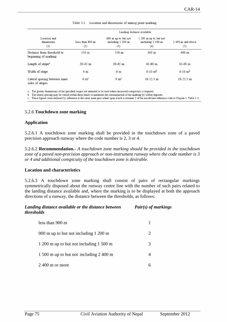
CAR-14
Page 75 Civil Aviation Authority of Nepal September 2012
5.2.6 Touchdown zone marking
Application
5.2.6.1 A touchdown zone marking shall be provided in the touchdown zone of a paved
precision approach runway where the code number is 2, 3 or 4.
5.2.6.2 Recommendation.- A touchdown zone marking should be provided in the touchdown
zone of a paved non-precision approach or non-instrument runway where the code number is 3
or 4 and additional conspicuity of the touchdown zone is desirable.
Location and characteristics
5.2.6.3 A touchdown zone marking shall consist of pairs of rectangular markings
symmetrically disposed about the runway centre line with the number of such pairs related to
the landing distance available and, where the marking is to be displayed at both the approach
directions of a runway, the distance between the thresholds, as follows:
Landing distance available or the distance between Pair(s) of markings
thresholds
less than 900 m 1
900 m up to but not including 1 200 m 2
1 200 m up to but not including 1 500 m 3
1 500 m up to but not including 2 400 m 4
2 400 m or more 6
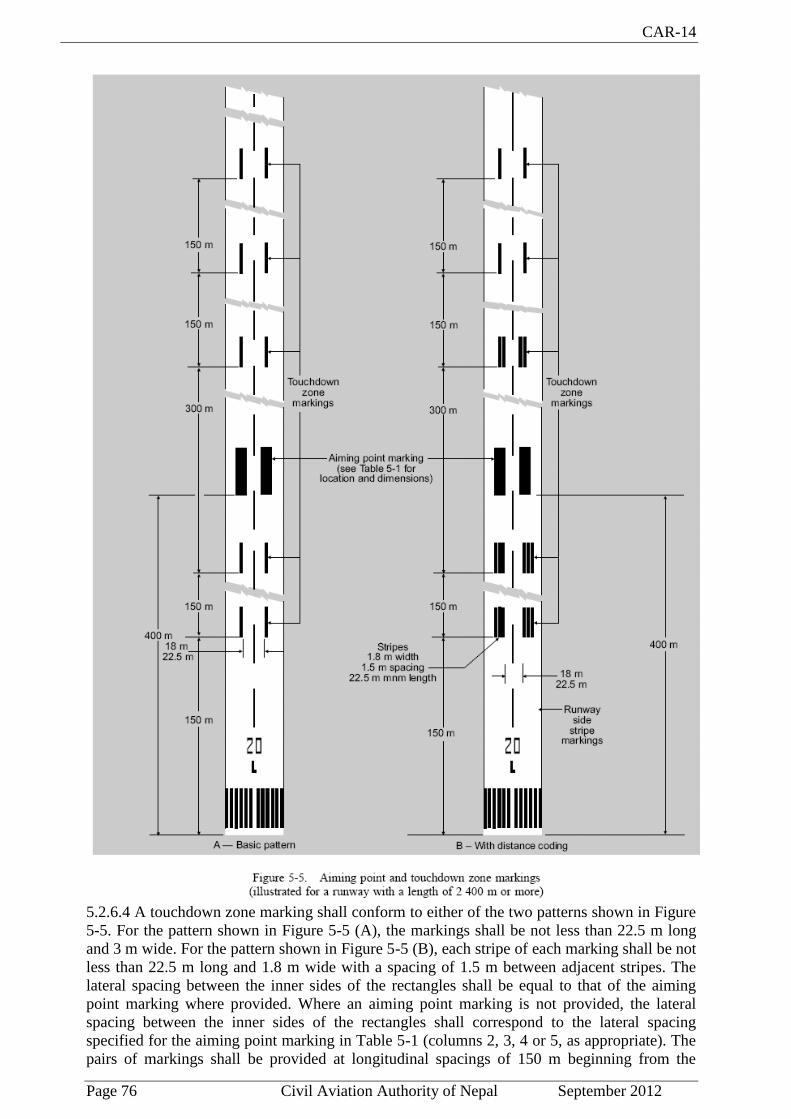
CAR-14
Page 76 Civil Aviation Authority of Nepal September 2012
5.2.6.4 A touchdown zone marking shall conform to either of the two patterns shown in Figure
5-5. For the pattern shown in Figure 5-5 (A), the markings shall be not less than 22.5 m long
and 3 m wide. For the pattern shown in Figure 5-5 (B), each stripe of each marking shall be not
less than 22.5 m long and 1.8 m wide with a spacing of 1.5 m between adjacent stripes. The
lateral spacing between the inner sides of the rectangles shall be equal to that of the aiming
point marking where provided. Where an aiming point marking is not provided, the lateral
spacing between the inner sides of the rectangles shall correspond to the lateral spacing
specified for the aiming point marking in Table 5-1 (columns 2, 3, 4 or 5, as appropriate). The
pairs of markings shall be provided at longitudinal spacings of 150 m beginning from the

CAR-14
Page 77 Civil Aviation Authority of Nepal September 2012
threshold except that pairs of touchdown zone markings coincident with or located within 50 m
of an aiming point marking shall be deleted from the pattern.
5.2.6.5 Recommendation.- On a non-precision approach runway where the code number is 2,
an additional pair of touchdown zone marking stripes should be provided 150 m beyond the
beginning of the aiming point marking.
5.2.7 Runway side stripe marking
Application
5.2.7.1 A runway side stripe marking shall be provided between the thresholds of a paved
runway where there is a lack of contrast between the runway edges and the shoulders or the
surrounding terrain.
5.2.7.2 A runway side stripe marking shall be provided on a precision approach runway
irrespective of the contrast between the runway edges and the shoulders or the surrounding
terrain.
Location
5.2.7.3 A runway side stripe marking shall consist of two stripes, one placed along each edge
of the runway with the outer edge of each stripe approximately on the edge of the runway,
except that, where the runway is greater than 60 m in width, the stripes shall be located 30 m
from the runway centre line.
5.2.7.4 Where a runway turn pad is provided, the runway side stripe marking shall be
continued between the runway and the runway turn pad.
Characteristics
5.2.7.5 A runway side stripe shall have an overall width of at least 0.9 m on runways 30 m or
more in width and at least 0.45 m on narrower runways.
5.2.8 Taxiway centre line marking
Application
5.2.8.1 Taxiway centre line marking shall be provided on a paved taxiway and apron where the
code number is 3 or 4 in such a way as to provide continuous guidance between the runway
centre line and aircraft stands.
5.2.8.2 Recommendation.- Taxiway centre line marking should be provided on a paved
taxiway and apron where the code number is 1 or 2 in such a way as to provide continuous
guidance between the runway centre line and aircraft stands.
5.2.8.3 Taxiway centre line marking shall be provided on a paved runway when the runway is
part of a standard taxi-route and:
a) there is no runway centre line marking; or
b) where the taxiway centre line is not coincident with the runway centre line.
5.2.8.4 Recommendation.- Where it is necessary to denote the proximity of a runway-holding
position, enhanced taxiway centre line marking should be provided.

CAR-14
Page 78 Civil Aviation Authority of Nepal September 2012
Note:- The provision of enhanced taxiway centre line marking may form part of runwy
incursion prevention measures.
5.2.8.5 Where provided, enhanced taxiway centre line marking shall be installed at all
taxiway/runway intersections at that aerodrome.
Location
5.2.8.6 Recommendation.- On a straight section of a taxiway the taxiway centre line marking
should be located along the taxiway centre line. On a taxiway curve the marking should
continue from the straight portion of the taxiway at a constant distance from the outside edge
of the curve.
Note.— See 3.9.6 and Figure 3-2.
5.2.8.7 Recommendation.- At an intersection of a taxiway with a runway where the taxiway
serves as an exit from the runway, the taxiway centre line marking should be curved into the
runway centre line marking as shown in Figures 5-6 and 5-25. The taxiway centre line
marking should be extended parallel to the runway centre line marking for a distance of at
least 60 m beyond the point of tangency where the code number is 3 or 4, and for a distance of
at least 30 m where the code number is 1 or 2.
5.2.8.8 Recommendation.- Where taxiway centre line marking is provided on a runway in
accordance with 5.2.8.3, the marking should be located on the centre line of the designated
taxiway.
5.2.8.9 Where provided, an enhanced taxiway centre line marking shall be extend from the
runway-holding position pattern A (as defined in Figure 5-6, Taxiway markings) to a distance
of up to 45 m(a minimum of three(3) dashed lines) in the direction of travel away from the
runway or to the next runway-holding position, if within 45 m distance.
Characteristics
5.2.8.10 A taxiway centre line marking shall be at least 15 cm in width and continuous in
length except where it intersects with a runway-holding position marking or an intermediate
holding position marking as shown in Figure 5-6.
5.2.8.11 Enhanced taxiway centre line marking shall be as shown in Figure 5-7.

CAR-14
Page 79 Civil Aviation Authority of Nepal September 2012
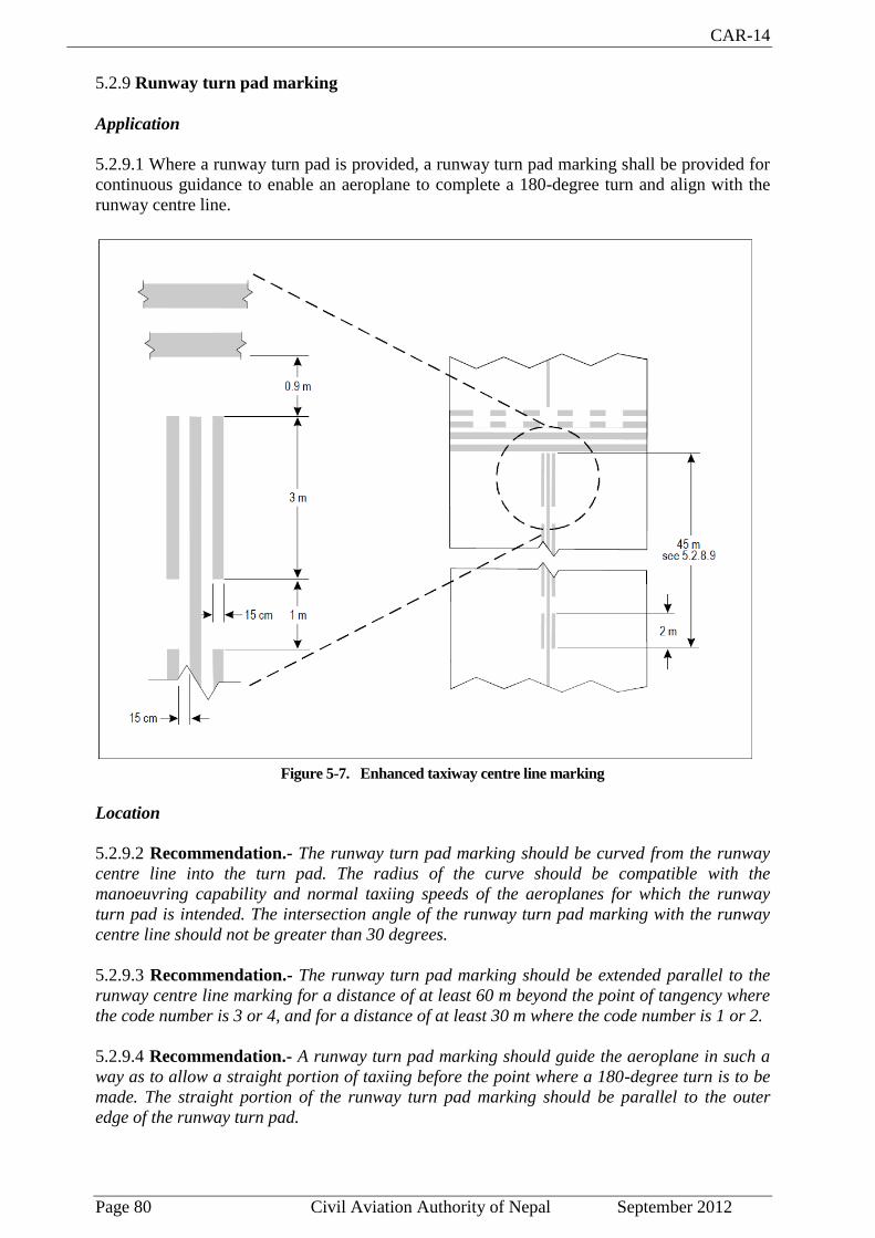
CAR-14
Page 80 Civil Aviation Authority of Nepal September 2012
5.2.9 Runway turn pad marking
Application
5.2.9.1 Where a runway turn pad is provided, a runway turn pad marking shall be provided for
continuous guidance to enable an aeroplane to complete a 180-degree turn and align with the
runway centre line.
Figure 5-7. Enhanced taxiway centre line marking
Location
5.2.9.2 Recommendation.- The runway turn pad marking should be curved from the runway
centre line into the turn pad. The radius of the curve should be compatible with the
manoeuvring capability and normal taxiing speeds of the aeroplanes for which the runway
turn pad is intended. The intersection angle of the runway turn pad marking with the runway
centre line should not be greater than 30 degrees.
5.2.9.3 Recommendation.- The runway turn pad marking should be extended parallel to the
runway centre line marking for a distance of at least 60 m beyond the point of tangency where
the code number is 3 or 4, and for a distance of at least 30 m where the code number is 1 or 2.
5.2.9.4 Recommendation.- A runway turn pad marking should guide the aeroplane in such a
way as to allow a straight portion of taxiing before the point where a 180-degree turn is to be
made. The straight portion of the runway turn pad marking should be parallel to the outer
edge of the runway turn pad.
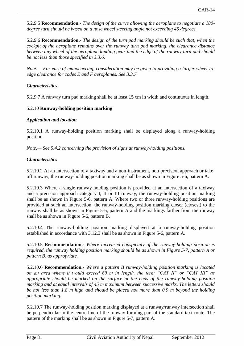
CAR-14
Page 81 Civil Aviation Authority of Nepal September 2012
5.2.9.5 Recommendation.- The design of the curve allowing the aeroplane to negotiate a 180-
degree turn should be based on a nose wheel steering angle not exceeding 45 degrees.
5.2.9.6 Recommendation.- The design of the turn pad marking should be such that, when the
cockpit of the aeroplane remains over the runway turn pad marking, the clearance distance
between any wheel of the aeroplane landing gear and the edge of the runway turn pad should
be not less than those specified in 3.3.6.
Note.— For ease of manoeuvring, consideration may be given to providing a larger wheel-to-
edge clearance for codes E and F aeroplanes. See 3.3.7.
Characteristics
5.2.9.7 A runway turn pad marking shall be at least 15 cm in width and continuous in length.
5.2.10 Runway-holding position marking
Application and location
5.2.10.1 A runway-holding position marking shall be displayed along a runway-holding
position.
Note.— See 5.4.2 concerning the provision of signs at runway-holding positions.
Characteristics
5.2.10.2 At an intersection of a taxiway and a non-instrument, non-precision approach or take-
off runway, the runway-holding position marking shall be as shown in Figure 5-6, pattern A.
5.2.10.3 Where a single runway-holding position is provided at an intersection of a taxiway
and a precision approach category I, II or III runway, the runway-holding position marking
shall be as shown in Figure 5-6, pattern A. Where two or three runway-holding positions are
provided at such an intersection, the runway-holding position marking closer (closest) to the
runway shall be as shown in Figure 5-6, pattern A and the markings farther from the runway
shall be as shown in Figure 5-6, pattern B.
5.2.10.4 The runway-holding position marking displayed at a runway-holding position
established in accordance with 3.12.3 shall be as shown in Figure 5-6, pattern A.
5.2.10.5 Recommendation.- Where increased conspicuity of the runway-holding position is
required, the runway holding position marking should be as shown in Figure 5-7, pattern A or
pattern B, as appropriate.
5.2.10.6 Recommendation.- Where a pattern B runway-holding position marking is located
on an area where it would exceed 60 m in length, the term “CAT II” or “CAT III” as
appropriate should be marked on the surface at the ends of the runway-holding position
marking and at equal intervals of 45 m maximum between successive marks. The letters should
be not less than 1.8 m high and should be placed not more than 0.9 m beyond the holding
position marking.
5.2.10.7 The runway-holding position marking displayed at a runway/runway intersection shall
be perpendicular to the centre line of the runway forming part of the standard taxi-route. The
pattern of the marking shall be as shown in Figure 5-7, pattern A.

CAR-14
Page 82 Civil Aviation Authority of Nepal September 2012
5.2.11 Intermediate holding position marking
Application and location
5.2.11.1 Recommendation.- An intermediate holding position marking should be displayed
along an intermediate holding position.
5.2.11.2 Recommendation.— An intermediate holding position marking should be displayed
at the exit boundary of a remote de-icing/anti-icing facility adjoining a taxiway.
5.2.11.3 Where an intermediate holding position marking is displayed at an intersection of two
paved taxiways, it shall be located across the taxiway at sufficient distance from the near edge
of the intersecting taxiway to ensure safe clearance between taxiing aircraft. It shall be
coincident with a stop bar or intermediate holding position lights, where provided.
5.2.11.4 The distance between an intermediate holding position marking at the exit boundary
of a remote de-icing/ anti-icing facility and the centre line of the adjoining taxiway shall not be
less than the dimension specified in Table 3-1, column 11.
Characteristics
5.2.11.5 An intermediate holding position marking shall consist of a single broken line as
shown in Figure 5-6.

CAR-14
Page 83 Civil Aviation Authority of Nepal September 2012
5.2.12 VOR aerodrome check-point marking
Application
5.2.12.1 When a VOR aerodrome check-point is established, it shall be indicated by a VOR
aerodrome check-point marking and sign.
Note.— See 5.4.4 for VOR aerodrome check-point sign.
5.2.12.2 Site selection
Note.— Guidance on the selection of sites for VOR aerodrome check-points is given in ICAO
Annex 10, Part 1, Attachment E.
Location
5.2.12.3 A VOR aerodrome check-point marking shall be centred on the spot at which an
aircraft is to be parked to receive the correct VOR signal.
Characteristics
5.2.12.4 A VOR aerodrome check-point marking shall consist of a circle 6 m in diameter and
have a line width of 15 cm (see Figure 5-8 (A)).
5.2.12.5 Recommendation.— When it is preferable for an aircraft to be aligned in a specific
direction, a line should be provided that passes through the centre of the circle on the desired
azimuth. The line should extend 6 m outside the circle in the desired direction of heading and
terminate in an arrowhead. The width of the line should be 15 cm (see Figure 5-8 (B)).
5.2.12.6 Recommendation.— A VOR aerodrome checkpoint marking should preferably be
white in colour but should differ from the colour used for the taxiway markings.
Note.— To provide contrast, markings may be bordered with black.
5.2.13 Aircraft stand markings
Note.— Guidance on the layout of aircraft stand markings is contained in the ICAO
Aerodrome Design Manual, Part 4.
Application
5.2.13.1 Recommendation.— Aircraft stand markings should be provided for designated
parking positions on a paved apron and on a de-icing/ anti-icing facility.
Location
5.2.13.2 Recommendation.— Aircraft stand markings on paved apron and on a de-icing/
anti-icing facility should be located so as to provide the clearances specified in 3.13.6 and
3.15.9 respectively, when the nose wheel follows the stand marking.
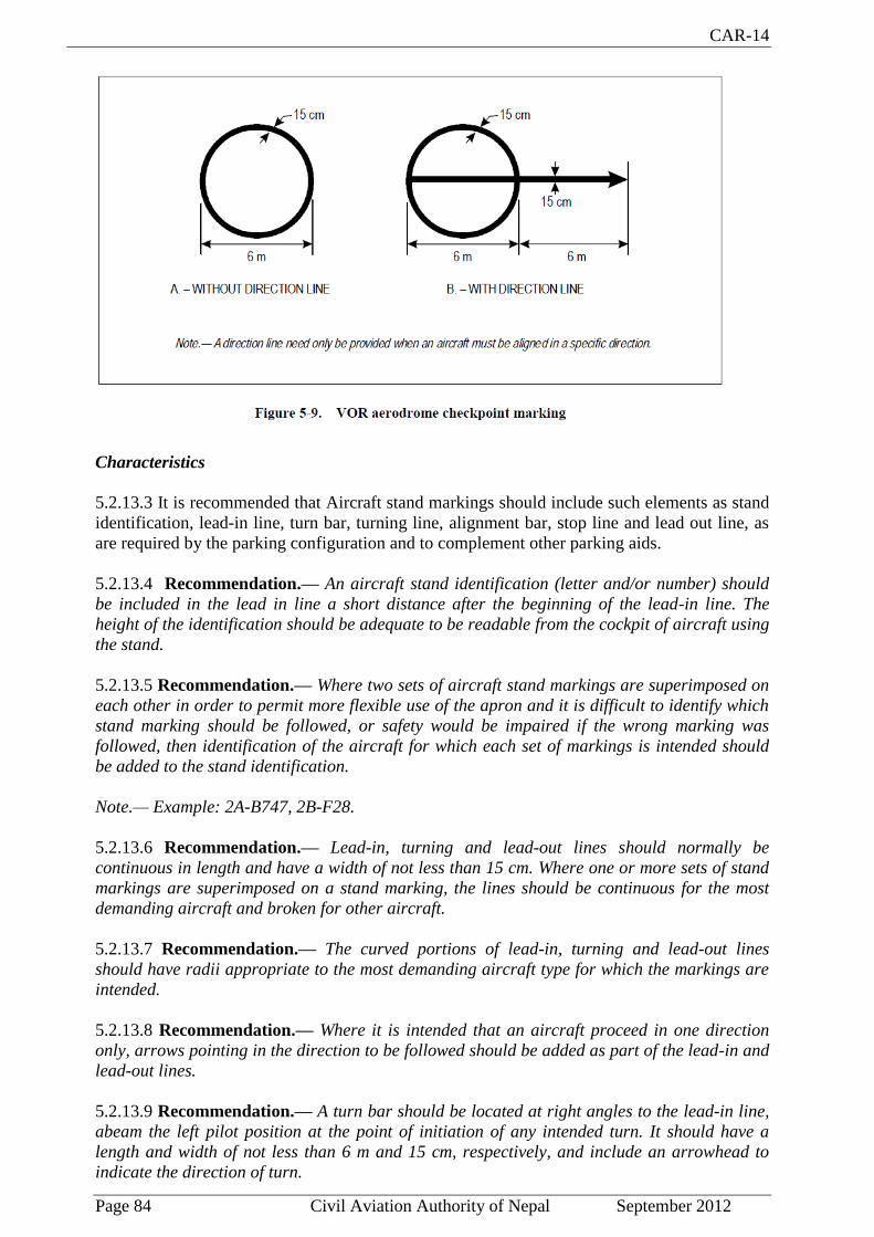
CAR-14
Page 84 Civil Aviation Authority of Nepal September 2012
Characteristics
5.2.13.3 It is recommended that Aircraft stand markings should include such elements as stand
identification, lead-in line, turn bar, turning line, alignment bar, stop line and lead out line, as
are required by the parking configuration and to complement other parking aids.
5.2.13.4 Recommendation.— An aircraft stand identification (letter and/or number) should
be included in the lead in line a short distance after the beginning of the lead-in line. The
height of the identification should be adequate to be readable from the cockpit of aircraft using
the stand.
5.2.13.5 Recommendation.— Where two sets of aircraft stand markings are superimposed on
each other in order to permit more flexible use of the apron and it is difficult to identify which
stand marking should be followed, or safety would be impaired if the wrong marking was
followed, then identification of the aircraft for which each set of markings is intended should
be added to the stand identification.
Note.— Example: 2A-B747, 2B-F28.
5.2.13.6 Recommendation.— Lead-in, turning and lead-out lines should normally be
continuous in length and have a width of not less than 15 cm. Where one or more sets of stand
markings are superimposed on a stand marking, the lines should be continuous for the most
demanding aircraft and broken for other aircraft.
5.2.13.7 Recommendation.— The curved portions of lead-in, turning and lead-out lines
should have radii appropriate to the most demanding aircraft type for which the markings are
intended.
5.2.13.8 Recommendation.— Where it is intended that an aircraft proceed in one direction
only, arrows pointing in the direction to be followed should be added as part of the lead-in and
lead-out lines.
5.2.13.9 Recommendation.— A turn bar should be located at right angles to the lead-in line,
abeam the left pilot position at the point of initiation of any intended turn. It should have a
length and width of not less than 6 m and 15 cm, respectively, and include an arrowhead to
indicate the direction of turn.

CAR-14
Page 85 Civil Aviation Authority of Nepal September 2012
Note.— The distances to be maintained between the turn bar and the lead-in line may vary
according to different aircraft types, taking into account the pilot’s field of view.
5.2.13.10 Recommendation.— If more than one turn bar and/or stop line is required, they
should be coded.
5.2.13.11 Recommendation.— An alignment bar should be placed so as to be coincident with
the extended centre line of the aircraft in the specified parking position and visible to the pilot
during the final part of the parking manoeuvre. It should have a width of not less than 15 cm.
5.2.13.12 Recommendation.— A stop line should be located at right angles to the alignment
bar, abeam the left pilot position at the intended point of stop. It should have a length and
width of not less than 6 m and 15 cm, respectively.
Note — The distances to be maintained between the stop line and the lead-in line may vary
according to different aircraft types, taking into account the pilot’s field of view.
5.2.14 Apron safety lines
Note.— Guidance on apron safety lines is contained in the ICAO Aerodrome Design Manual,
Part 4.
Application
5.2.14.1 Recommendation.— Apron safety lines should be provided on a paved apron as
required by the parking configurations and ground facilities.
Location
5.2.14.2 Apron safety lines shall be located so as to define the areas intended for use by ground
vehicles and other aircraft servicing equipment, etc., to provide safe separation from aircraft.
Characteristics
5.2.14.3 Recommendation.— Apron safety lines should include such elements as wing tip
clearance lines and service road boundary lines as required by the parking configurations and
ground facilities.
5.2.14.4 Recommendation.— An apron safety line should be continuous in length and at least
10 cm in width.
5.2.15 Road-holding position marking
Application
5.2.15.1 A road-holding position marking shall be provided at all road entrances to a runway.
Location
5.2.15.2 The road-holding position marking shall be located across the road at the holding
position.

CAR-14
Page 86 Civil Aviation Authority of Nepal September 2012
Characteristics
5.2.15.3 The road-holding position marking shall be in accordance with the local road traffic
regulations.
5.2.16 Mandatory instruction marking
Note.— Guidance on mandatory instruction marking is given in the Aerodrome Design
Manual, Part 4.
Application
5.2.16.1 Where it is impracticable to install a mandatory instruction sign in accordance with
5.4.2.1, a mandatory instruction marking shall be provided on the surface of the pavement.
5.2.16.2 Recommendation.— Where operationally required, such as on taxiways exceeding
60 m in width, a mandatory instruction sign should be supplemented by a mandatory
instruction marking.
Location
5.2.16.3 The mandatory instruction marking on taxiways where the code letter is A, B, C or D shall be located across the taxiway equally placed about the taxiway centre line and on the holding side of the runway-holding position marking as shown in Figure 5-10 (A). The distance between the nearest edge of the marking and the run way-holding position marking or the taxiway centre line marking shall be not less than 1 m.
5.2.16.4 The mandatory instruction marking on taxiways where the code letter is E or F shall be located on both sides of the taxiway centre line marking and on the holding side of the run way holding position marking as shown in Figure 5-10 (B). The distance between the nearest edge of the marking and the runway-holding position marking or the taxiway centre line marking shall be not less than 1 m.
5.2.16.5 Recommendation.— Except where operationally required, a mandatory instruction marking should not be located on a runway.
Characteristics
5.2.16.6 A mandatory instruction marking shall consist of an inscription in white on a red background. Except for a NO ENTRY marking, the inscription shall provide information identical to that of the associated mandatory instruction sign
5.2.16.7 A NO ENTRY marking shall consist of an inscription in white reading NO ENTRY on a red background.
5.2.16.8 Where there is insufficient contrast between the marking and the pavement surface,
the mandatory instruction marking shall include an appropriate border, preferably white or
black.
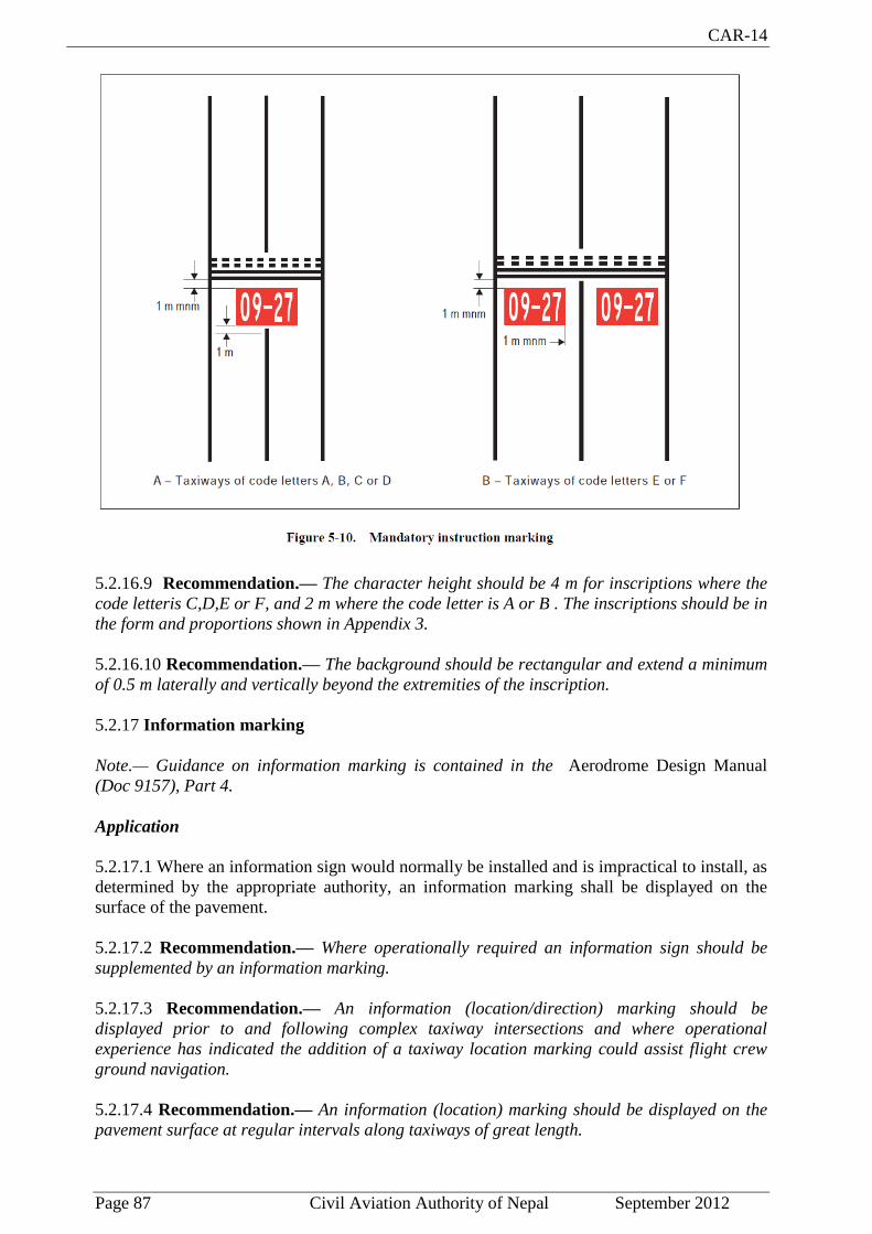
CAR-14
Page 87 Civil Aviation Authority of Nepal September 2012
5.2.16.9 Recommendation.— The character height should be 4 m for inscriptions where the
code letteris C,D,E or F, and 2 m where the code letter is A or B . The inscriptions should be in
the form and proportions shown in Appendix 3.
5.2.16.10 Recommendation.— The background should be rectangular and extend a minimum
of 0.5 m laterally and vertically beyond the extremities of the inscription.
5.2.17 Information marking
Note.— Guidance on information marking is contained in the Aerodrome Design Manual
(Doc 9157), Part 4.
Application
5.2.17.1 Where an information sign would normally be installed and is impractical to install, as
determined by the appropriate authority, an information marking shall be displayed on the
surface of the pavement.
5.2.17.2 Recommendation.— Where operationally required an information sign should be
supplemented by an information marking.
5.2.17.3 Recommendation.— An information (location/direction) marking should be
displayed prior to and following complex taxiway intersections and where operational
experience has indicated the addition of a taxiway location marking could assist flight crew
ground navigation.
5.2.17.4 Recommendation.— An information (location) marking should be displayed on the
pavement surface at regular intervals along taxiways of great length.
CAR-14
Page 88 Civil Aviation Authority of Nepal September 2012
Location
5.2.17.5 Recommendation.— The information marking should be displayed across the
surface of the taxiway or apron where necessary and positioned so as to be legible from the
cockpit of an approaching aircraft.
Characteristics
5.2.17.6 An information marking shall consist of:
a) an inscription in yellow upon a black background, when it replaces or supplements a
location sign; and
b) an inscription in black upon a yellow background, when it replaces or supplements a
direction or destination sign.
5.2.17.7 Where there is insufficient contrast between the marking background and the
pavement surface, the marking shall include:
a) a black border where the inscriptions are in black; and
b) a yellow border where the inscriptions are in yellow.
5.2.17.8 Recommendation.— The character height should be 4 m. The inscriptions should be
in the form and proportions shown in Appendix 3
5.3 Lights
5.3.1 General
Lights which may endanger the safety of aircraft
5.3.1.1 A non-aeronautical ground light near an aerodrome which might endanger the safety of
aircraft shall be extinguished, screened or otherwise modified so as to eliminate the source of
danger.
Laser emissions which may endanger the safety of aircraft
5.3.1.2 Recommendation.— To protect the safety of aircraft against the hazardous effects of
laser emitters, the following protected zones should be established around aerodromes:
- a laser-beam free flight zone (LFFZ)
- a laser-beam critical flight zone (LCFZ)
- a laser-beam sensitive flight zone (LSFZ).
Note 1.— Figures 5-10, 5-11 and 5-12 may be used to determine the exposure levels and
distances that adequately protect flight operations.
Note 2.— The restrictions on the use of laser beams in the three protected flight zones, LFFZ,
LCFZ and LSFZ, refer to visible laser beams only. Laser emitters operated by the authorities
in a manner compatible with flight safety are excluded. In all navigable air space, the
irradiance level of any laser beam, visible or invisible, is expected to be less than or equal to
the maximum permissible exposure (MPE) unless such emission has been notified to the
authority and permission obtained.

CAR-14
Page 89 Civil Aviation Authority of Nepal September 2012
Note 3.— The protected flight zones are established in order to mitigate the risk of operating
laser emitters in the vicinity of aerodromes.
Note 4.— Further guidance on how to protect flight operations from the hazardous effects of
laser emitters is contained in the Manual on Laser Emitters and Flight Safety (Doc 9815).
Note 5.— See also Annex 11 — Air Traffic Services, Chapter 2.
Lights which may cause confusion
5.3.1.3 Recommendation.— A non-aeronautical ground light which, by reason of its intensity,
configuration or colour, might prevent, or cause confusion in, the clear interpretation of
aeronautical ground lights should be extinguished, screened or otherwise modified so as to
eliminate such a possibility. In particular, attention should be directed to a non-aeronautical
ground light visible from the air within the areas described hereunder:
a) Instrument runway — code number 4:
within the areas before the threshold and beyond the end of the runway extending at
least 4 500 m in length from the threshold and runway end and 750 m either side of the
extended runway centre line in width.
b) Instrument runway — code number 2 or 3:
as in a), except that the length should be at least 3 000 m.
c) Instrument runway — code number 1; and non-instrument runway:
within the approach area.
Aeronautical ground lights which may cause confusion to mariners
Note.— In the case of aeronautical ground lights near navigable waters, consideration needs
to be given to ensuring that the lights do not cause confusion to mariners.
Light fixtures and supporting structures
Note.— See 9.9 for information regarding siting of equipment and installations on operational
areas, and the Aerodrome Design Manual (Doc 9157), Part 6 or guidance on frangibility of
light fixtures and supporting structures.
Elevated approach lights
5.3.1.4 Elevated approach lights and their supporting structures shall be frangible except that,
in that portion of the approach lighting system beyond 300 m from the threshold:
a) where the height of a supporting structure exceeds 12 m, the frangibility requirement
shall apply to the top 12 m only; and
b) where a supporting structure is surrounded by non-frangible objects, only that part of
the structure that extends above the surrounding objects shall be frangible.
5.3.1.5 When an approach light fixture or supporting structure is not in itself sufficiently
conspicuous, it shall be suitably marked.

CAR-14
Page 90 Civil Aviation Authority of Nepal September 2012
Elevated lights
5.3.1.6 Elevated runway, stopway and taxiway lights shall be frangible. Their height shall be
sufficiently low to preserve clearance for propellers and for the engine pods of jet aircraft.
Surface lights
5.3.1.7 Light fixtures inset in the surface of runways, stopways, taxiways and aprons shall be
so designed and fitted as to withstand being run over by the wheels of an aircraft without
damage either to the aircraft or to the lights themselves.
5.3.1.8 Recommendation.— The temperature produced by conduction or radiation at the
interface between an installed inset light and an aircraft tire should not exceed 160°C during a
10-minute period of exposure.
Note.— Guidance on measuring the temperature of inset lights is given in the Aerodrome
Design Manual, Part 4.

CAR-14
Page 91 Civil Aviation Authority of Nepal September 2012

CAR-14
Page 92 Civil Aviation Authority of Nepal September 2012
Light intensity and control
Note.— In dusk or poor visibility conditions by day, lighting can be more effective than
marking. For lights to be effective in such conditions or in poor visibility by night, they must be
of adequate intensity. To obtain the required intensity, it will usually be necessary to make the
light directional, in which case the arcs over which the light shows will have to be adequate
and so orientated as to meet the operational requirements. The runway lighting system will
have to be considered as a whole, to ensure that the relative light intensities are suitably
matched to the same end. (See Attachment A, Section 14, and the Aerodrome Design Manual,
Part 4.)
5.3.1.9 The intensity of runway lighting shall be adequate for the minimum conditions of
visibility and ambient light in which use of the runway is intended, and compatible with that of
the nearest section of the approach lighting system when provided.
Note.— While the lights of an approach lighting system may be of higher intensity than the
runway lighting, it is good practice to avoid abrupt changes in intensity as these could give a
pilot a false impression that the visibility is changing during approach.
5.3.1.10 Where a high-intensity lighting system is provided, a suitable intensity control shall be
incorporated to allow for adjustment of the light intensity to meet the prevailing conditions.
Separate intensity controls or other suitable methods shall be provided to ensure that the
following systems, when installed, can be operated at compatible intensities:
- approach lighting system;
- runway edge lights;
- runway threshold lights;
- runway end lights;
- runway centre line lights;
- runway touchdown zone lights; and
- taxiway centre line lights.
5.3.1.11 On the perimeter of and within the ellipse defining the main beam in Appendix 2,
Figures A2-1 to A2-10, the maximum light intensity value shall not be greater than three times
the minimum light intensity value measured in accordance with Appendix 2, collective notes
for Figures A2-1 to A2-11, Note 2.
5.3.1.12 On the perimeter of and within the rectangle defining the main beam in Appendix 2,
Figures A2-12 to A2-20, the maximum light intensity value shall not be greater than three
times the minimum light intensity value measured in accordance with Appendix 2, collective
notes for Figures A2-12 to A2-21, Note 2.
5.3.2 Emergency lighting
Application
5.3.2.1 Recommendation.— At an aerodrome provided with runway lighting and without a
secondary power supply, sufficient emergency lights should be conveniently available for
installation on at least the primary runway in the event of failure of the normal lighting system.

CAR-14
Page 93 Civil Aviation Authority of Nepal September 2012
Note.— Emergency lighting may also be useful to mark obstacles or delineate taxiways and
apron areas.
Location
5.3.2.2 Recommendation.— When installed on a runway the emergency lights should, as a
minimum, conform to the configuration required for a non-instrument runway.
Characteristics
5.3.2.3 Recommendation.— The colour of the emergency lights should conform to the colour
requirements for runway lighting, except that, where the provision of coloured lights at the
threshold and the runway end is not practicable, all lights may be variable white or as close to
variable white as practicable.
5.3.3 Aeronautical beacons
Application
5.3.3.1 Where operationally necessary an aerodrome beacon or an identification beacon shall
be provided at each aerodrome intended for use at night.
5.3.3.2 The operational requirement shall be determined having regard to the requirements of
the air traffic using the aerodrome, the conspicuity of the aerodrome features in relation to its
surroundings and the installation of other visual and non-visual aids useful in locating the
aerodrome.
Aerodrome beacon
5.3.3.3 An aerodrome beacon shall be provided at an aerodrome intended for use at night if one
or more of the following conditions exist:
a) aircraft navigate predominantly by visual means;
b) reduced visibilities are frequent; or
c) it is difficult to locate the aerodrome from the air due to surrounding lights or
terrain.
Location
5.3.3.4 The aerodrome beacon shall be located on or adjacent to the aerodrome in an area of
low ambient background lighting.
5.3.3.5 Recommendation.— The location of the beacon should be such that the beacon is not
shielded by objects in significant directions and does not dazzle a pilot approaching to land.
Characteristics
5.3.3.6 The aerodrome beacon shall show either coloured flashes alternating with white
flashes, or white flashes only. The frequency of total flashes shall be from 20 to 30 per minute.
Where used, the coloured flashes emitted by beacons at land aerodromes shall be green and
coloured flashes emitted by beacons at water aerodromes shall be yellow. In the case of a

CAR-14
Page 94 Civil Aviation Authority of Nepal September 2012
combined water and land aerodrome, coloured flashes, if used, shall have the colour
characteristics of whichever section of the aerodrome is designated as the principal facility.
5.3.3.7 The light from the beacon shall show at all angles of azimuth. The vertical light
distribution shall extend upwards from an elevation of not more than 1° to an elevation to be
sufficient to provide guidance at the maximum elevation at which the beacon is intended to be
used and the effective intensity of the flash shall be not less than 2 000 cd.
Note.— At locations where a high ambient background lighting level cannot be avoided, the
effective intensity of the flash may be required to be increased by a factor up to a value of 10.
Identification beacon
Application
5.3.3.8 An identification beacon shall be provided at an aerodrome which is intended for use at
night and cannot be easily identified from the air by other means.
Location
5.3.3.9 The identification beacon shall be located on the aerodrome in an area of low ambient
background lighting.
5.3.3.10 Recommendation.— The location of the beacon should be such that the beacon is not
shielded by objects in significant directions and does not dazzle a pilot approaching to land.
Characteristics
5.3.3.11 An identification beacon at a land aerodrome shall show at all angles of azimuth. The
vertical light distribution shall extend upwards from an elevation of not more than 1° to an
elevation to be sufficient to provide guidance at the maximum elevation at which the beacon is
intended to be used and the effective intensity of the flash shall be not less than 2000 cd.
Note.— At locations where a high ambient background lighting level cannot be avoided, the
effective intensity of the flash may be required to be increased by a factor up to a value of 10.
5.3.3.12 An identification beacon shall show flashing green at a land aerodrome and flashing-
yellow at a water aerodrome.
5.3.3.13 The identification characters shall be transmitted in the International Morse Code.
5.3.3.14 Recommendation.— The speed of transmission should be between six and eight
words per minute, the corresponding range of duration of the Morse dots being from 0.15 to
0.2 seconds per dot.
5.3.4 Approach lighting systems
Application
5.3.4.1 Application
A.— Non-instrument runway

CAR-14
Page 95 Civil Aviation Authority of Nepal September 2012
Recommendation.— Where physically practicable, a simple approach lighting system as
specified in 5.3.4.2 to 5.3.4.9 should be provided to serve a non-instrument runway where the
code number is 3 or 4 and intended for use at night, except when the runway is used only in
conditions of good visibility, and sufficient guidance is provided by other visual aids.
Note.— A simple approach lighting system can also provide visual guidance by day.
B.— Non-precision approach runway
Where physically practicable, a simple approach lighting system as specified in 5.3.4.2 to
5.3.4.9 shall be provided to serve a non-precision approach runway, except when the runway is
used only in conditions of good visibility or sufficient guidance is provided by other visual
aids.
Note.— It is advisable to give consideration to the installation of a precision approach
category I lighting system or to the addition of a runway lead-in lighting system.
C.— Precision approach runway category I
Where physically practicable, a precision approach category I lighting system as specified in
5.3.4.10 to 5.3.4.21 shall be provided to serve a precision approach runway category I.
D.— Precision approach runway categories II and III
A precision approach category II and III lighting system as specified in 5.3.4.22 to 5.3.4.39
shall be provided to serve a precision approach runway category II or III.
Simple approach lighting system
Location
5.3.4.2 A simple approach lighting system shall consist of a row of lights on the extended
centre line of the runway extending, whenever possible, over a distance of not less than 420 m
from the threshold with a row of lights forming a crossbar 18 m or 30 m in length at a distance
of 300 m from the threshold.
5.3.4.3 The lights forming the crossbar shall be as nearly as practicable in a horizontal straight
line at right angles to, and bisected by, the line of the centre line lights. The lights of the
crossbar shall be spaced so as to produce a linear effect, except that, when a crossbar of 30 m is
used, gaps may be left on each side of the centre line. These gaps shall be kept to a minimum
to meet local requirements and each shall not exceed 6 m.
Note 1.— Spacings for the crossbar lights between 1 m and 4 m are in use. Gaps on each side
of the centre line may improve directional guidance when approaches are made with a lateral
error, and facilitate the movement of rescue and fire fighting vehicles.
Note 2.— See Attachment A, Section 11 for guidance on installation tolerances.
5.3.4.4 The lights forming the centre line shall be placed at longitudinal intervals of 60 m,
except that, when it is desired to improve the guidance, an interval of 30 m may be used. The
innermost light shall be located either 60 m or 30 m from the threshold, depending on the
longitudinal interval selected for the centre line lights.

CAR-14
Page 96 Civil Aviation Authority of Nepal September 2012
5.3.4.5 Recommendation.— If it is not physically possible to provide a centre line extending
for a distance of 420 m from the threshold, it should be extended to 300 m so as to include the
crossbar. If this is not possible, the centre line lights should be extended as far as practicable,
and each centre line light should then consist of a barrette at least 3 m in length. Subject to the
approach system having a crossbar at 300 m from the threshold, an additional crossbar may
be provided at 150 m from the threshold.
5.3.4.6 The system shall lie as nearly as practicable in the horizontal plane passing through the
threshold, provided that:
a) no object other than an ILS or MLS azimuth antenna shall protrude through the plane
of the approach lights within a distance of 60 m from the centre line of the system; and
b) no light other than a light located within the central part of a crossbar or a centre line
barrette (not their extremities) shall be screened from an approaching aircraft.
Any ILS or MLS azimuth antenna protruding through the plane of the lights shall be treated as
an obstacle and marked and lighted accordingly.
Characteristics
5.3.4.7 The lights of a simple approach lighting system shall be fixed lights and the colour of
the lights shall be such as to ensure that the system is readily distinguishable from other
aeronautical ground lights, and from extraneous lighting if present. Each centre line light shall
consist of either:
a) a single source; or
b) a barrette at least 3 m in length.
Note 1.— When the barrette as in b) is composed of lights approximating to point sources, a
spacing of 1.5 m between adjacent lights in the barrette has been found satisfactory.
Note 2.— It may be advisable to use barrettes 4 m in length if it is anticipated that the simple
approach lighting system will be developed into a precision approach lighting system.
Note 3.— At locations where identification of the simple approach lighting system is difficult at
night due to surrounding lights, sequence flashing lights installed in the outer portion of the
system may resolve this problem.
5.3.4.8 Recommendation.— Where provided for a non-instrument runway, the lights should
show at all angles in azimuth necessary to a pilot on base leg and final approach. The intensity
of the lights should be adequate for all conditions of visibility and ambient light for which the
system has been provided.
5.3.4.9 Recommendation.— Where provided for a non-precision approach runway, the lights
should show at all angles in azimuth necessary to the pilot of an aircraft which on final
approach does not deviate by an abnormal amount from the path defined by the non-visual aid.
The lights should be designed to provide guidance during both day and night in the most
adverse conditions of visibility and ambient light for which it is intended that the system should
remain usable.

CAR-14
Page 97 Civil Aviation Authority of Nepal September 2012
Precision approach category I lighting system
Location
5.3.4.10 A precision approach category I lighting system shall consist of a row of lights on the
extended centre line of the runway extending, wherever possible, over a distance of 900 m
from the runway threshold with a row of lights forming a crossbar 30 m in length at a distance
of 300 m from the runway threshold.
Note.— The installation of an approach lighting system of less than 900 m in length may result
in operational limitations on the use of the runway. See Attachment A, Section 11.
5.3.4.11 The lights forming the crossbar shall be as nearly as practicable in a horizontal straight
line at right angles to, and bisected by, the line of the centre line lights. The lights of the
crossbar shall be spaced so as to produce a linear effect, except that gaps may be left on each
side of the centre line. These gaps shall be kept to a minimum to meet local requirements and
each shall not exceed 6 m.
Note 1.— Spacings for the crossbar lights between 1 m and 4 m are in use. Gaps on each side
of the centre line may improve directional guidance when approaches are made with a lateral
error, and facilitate the movement of rescue and fire fighting vehicles.
Note 2.— See Attachment A, Section 11 for guidance on installation tolerances.
5.3.4.12 The lights forming the centre line shall be placed at longitudinal intervals of 30 m
with the innermost light located 30 m from the threshold.
5.3.4.13 The system shall lie as nearly as practicable in the horizontal plane passing through
the threshold, provided that:
a) no object other than an ILS or MLS azimuth antenna shall protrude through the
plane of the approach lights within a distance of 60 m from the centre line of the
system; and
b) no light other than a light located within the central part of a crossbar or a centre
line barrette (not their extremities) shall be screened from an approaching aircraft.
Any ILS or MLS azimuth antenna protruding through the plane of the lights shall be treated as
an obstacle and marked and lighted accordingly.
Characteristics
5.3.4.14 The centre line and crossbar lights of a precision approach category I lighting system
shall be fixed lights showing variable white. Each centre line light position shall consist of
either:
a) a single light source in the innermost 300 m of the centre line, two light sources in
the central 300 m of the centre line and three light sources in the outer 300 m of the
centre line to provide distance information; or
b) a barrette.
5.3.4.15 Where the serviceability level of the approach lights specified as a maintenance
objective in 10.4.10 can be demonstrated, each centre line light position may consist of either:
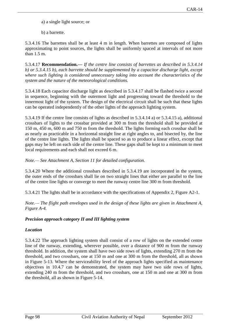
CAR-14
Page 98 Civil Aviation Authority of Nepal September 2012
a) a single light source; or
b) a barrette.
5.3.4.16 The barrettes shall be at least 4 m in length. When barrettes are composed of lights
approximating to point sources, the lights shall be uniformly spaced at intervals of not more
than 1.5 m.
5.3.4.17 Recommendation.— If the centre line consists of barrettes as described in 5.3.4.14
b) or 5.3.4.15 b), each barrette should be supplemented by a capacitor discharge light, except
where such lighting is considered unnecessary taking into account the characteristics of the
system and the nature of the meteorological conditions.
5.3.4.18 Each capacitor discharge light as described in 5.3.4.17 shall be flashed twice a second
in sequence, beginning with the outermost light and progressing toward the threshold to the
innermost light of the system. The design of the electrical circuit shall be such that these lights
can be operated independently of the other lights of the approach lighting system.
5.3.4.19 If the centre line consists of lights as described in 5.3.4.14 a) or 5.3.4.15 a), additional
crossbars of lights to the crossbar provided at 300 m from the threshold shall be provided at
150 m, 450 m, 600 m and 750 m from the threshold. The lights forming each crossbar shall be
as nearly as practicable in a horizontal straight line at right angles to, and bisected by, the line
of the centre line lights. The lights shall be spaced so as to produce a linear effect, except that
gaps may be left on each side of the centre line. These gaps shall be kept to a minimum to meet
local requirements and each shall not exceed 6 m.
Note.— See Attachment A, Section 11 for detailed configuration.
5.3.4.20 Where the additional crossbars described in 5.3.4.19 are incorporated in the system,
the outer ends of the crossbars shall lie on two straight lines that either are parallel to the line
of the centre line lights or converge to meet the runway centre line 300 m from threshold.
5.3.4.21 The lights shall be in accordance with the specifications of Appendix 2, Figure A2-1.
Note.— The flight path envelopes used in the design of these lights are given in Attachment A,
Figure A-4.
Precision approach category II and III lighting system
Location
5.3.4.22 The approach lighting system shall consist of a row of lights on the extended centre
line of the runway, extending, wherever possible, over a distance of 900 m from the runway
threshold. In addition, the system shall have two side rows of lights, extending 270 m from the
threshold, and two crossbars, one at 150 m and one at 300 m from the threshold, all as shown
in Figure 5-13. Where the serviceability level of the approach lights specified as maintenance
objectives in 10.4.7 can be demonstrated, the system may have two side rows of lights,
extending 240 m from the threshold, and two crossbars, one at 150 m and one at 300 m from
the threshold, all as shown in Figure 5-14.
CAR-14
Page 99 Civil Aviation Authority of Nepal September 2012

CAR-14
Page 100 Civil Aviation Authority of Nepal September 2012

CAR-14
Page 101 Civil Aviation Authority of Nepal September 2012
Note.— The length of 900 m is based on providing guidance for operations under category I, II
and III conditions. Reduced lengths may support category II and III operations but may impose
limitations on category I operations. See Attachment A, Section 11.
5.3.4.23 The lights forming the centre line shall be placed at longitudinal intervals of 30 m
with the innermost lights located 30 m from the threshold.
5.3.4.24 The lights forming the side rows shall be placed on each side of the centre line, at a
longitudinal spacing equal to that of the centre line lights and with the first light located 30 m
from the threshold. Where the serviceability level of the approach lights specified as
maintenance objectives in 10.4.7 can be demonstrated, lights forming the side rows may be
placed on each side of the centre line, at a longitudinal spacing of 60 m with the first light
located 60 m from the threshold. The lateral spacing (or gauge) between the innermost lights of
the side rows shall be not less than 18 m nor more than 22.5 m, and preferably 18 m, but in any
event shall be equal to that of the touchdown zone lights.
5.3.4.25 The crossbar provided at 150 m from the threshold shall fill in the gaps between the
centre line and side row lights.
5.3.4.26 The crossbar provided at 300 m from the threshold shall extend on both sides of the
centre line lights to a distance of 15 m from the centre line.
5.3.4.27 If the centre line beyond a distance of 300 m from the threshold consists of lights as
described in 5.3.4.31 b) or 5.3.4.32 b), additional crossbars of lights shall be provided at 450
m, 600 m and 750 m from the threshold.
5.3.4.28 Where the additional crossbars described in 5.3.4.27 are incorporated in the system,
the outer ends of these crossbars shall lie on two straight lines that either are parallel to the
centre line or converge to meet the runway centre line 300 m from the threshold.
5.3.4.29 The system shall lie as nearly as practicable in the horizontal plane passing through
the threshold, provided that:
a) no object other than an ILS or MLS azimuth antenna shall protrude through the
plane of the approach lights within a distance of 60 m from the centre line of the
system; and
b) no light other than a light located within the central part of a crossbar or a centre
line barrette (not their extremities) shall be screened from an approaching aircraft.
Any ILS or MLS azimuth antenna protruding through the plane of the lights shall be treated as
an obstacle and marked and lighted accordingly.
Characteristics
5.3.4.30 The centre line of a precision approach category II and III lighting system for the first
300 m from the threshold shall consist of barrettes showing variable white, except that, where
the threshold is displaced 300 m or more, the centre line may consist of single light sources
showing variable white. Where the serviceability level of the approach lights specified as
maintenance objectives in 10.4.7 can be demonstrated, the centre line of a precision approach
category II and III lighting system for the first 300 m from the threshold may consist of either:
a) barrettes, where the centre line beyond 300 m from the threshold consists of
barrettes as described in 5.3.4.32 a); or

CAR-14
Page 102 Civil Aviation Authority of Nepal September 2012
b) alternate single light sources and barrettes, where the centre line beyond 300 m
from the threshold consists of single light sources as described in 5.3.4.32 b), with
the innermost single light source located 30 m and the innermost barrette located 60
m from the threshold; or
c) single light sources where the threshold is displaced 300 m or more; all of which
shall show variable white.
5.3.4.31 Beyond 300 m from the threshold each centre line light position shall consist of either:
a) a barrette as used on the inner 300 m; or
c) two light sources in the central 300 m of the centre line and three light sources in
the outer 300 m of the centre line;
all of which shall show variable white.
5.3.4.32 Where the serviceability level of the approach lights specified as maintenance
objectives in 10.4.7 can be demonstrated, beyond 300 m from the threshold each centre line
light position may consist of either:
a) a barrette; or
b) a single light source;
all of which shall show variable white.
5.3.4.33 The barrettes shall be at least 4 m in length. When barrettes are composed of lights
approximating to point sources, the lights shall be uniformly spaced at intervals of not more
than 1.5 m.
5.3.4.34 Recommendation.— If the centre line beyond 300 m from the threshold consists of
barrettes as described in 5.3.4.31 a) or 5.3.4.32 a), each barrette beyond 300 m should be
supplemented by a capacitor discharge light, except where such lighting is considered
unnecessary taking into account the characteristics of the system and the nature of the
meteorological conditions.
5.3.4.35 Each capacitor discharge light shall be flashed twice a second in sequence, beginning
with the outermost light and progressing toward the threshold to the innermost light of the
system. The design of the electrical circuit shall be such that these lights can be operated
independently of the other lights of the approach lighting system.
5.3.4.36 The side row shall consist of barrettes showing red. The length of a side row barrette
and the spacing of its lights shall be equal to those of the touchdown zone light barrettes.
5.3.4.37 The lights forming the crossbars shall be fixed lights showing variable white. The
lights shall be uniformly spaced at intervals of not more than 2.7 m.
5.3.4.38 The intensity of the red lights shall be compatible with the intensity of the white
lights.
5.3.4.39 The lights shall be in accordance with the specifications of Appendix 2, Figures A2-1
and A2-2.

CAR-14
Page 103 Civil Aviation Authority of Nepal September 2012
Note.— The flight path envelopes used in the design of these lights are given in Attachment A,
Figure A-4.
5.3.5 Visual approach slope indicator systems
Application
5.3.5.1 A visual approach slope indicator system shall be provided to serve the approach to a
runway whether or not the runway is served by other visual approach aids or by non-visual
aids, where one or more of the following conditions exist:
a) the runway is used by turbojet or other aeroplanes with similar approach guidance
requirements;
b) the pilot of any type of aeroplane may have difficulty in judging the approach due
to:
1) inadequate visual guidance such as is experienced during an approach over
water or featureless terrain by day or in the absence of sufficient extraneous
lights in the approach area by night, or
2) misleading information such as is produced by deceptive surrounding terrain
or runway slopes;
c) the presence of objects in the approach area may involve serious hazard if an
aeroplane descends below the normal approach path, particularly if there are no
non-visual or other visual aids to give warning of such objects;
d) physical conditions at either end of the runway present a serious hazard in the event
of an aeroplane undershooting or overrunning the runway; and
e) terrain or prevalent meteorological conditions are such that the aeroplane may be
subjected to unusual turbulence during approach.
Note.— Guidance on the priority of installation of visual approach slope indicator systems is
contained in Attachment A, Section 12.
5.3.5.2 The standard visual approach slope indicator systems shall consist of the following:
a) T-VASIS and AT-VASIS conforming to the specifications contained in 5.3.5.6 to
5.3.5.22 inclusive;
b) PAPI and APAPI systems conforming to the specifications contained in 5.3.5.23 to
5.3.5.40 inclusive; as shown in Figure 5-16.

CAR-14
Page 104 Civil Aviation Authority of Nepal September 2012
5.3.5.3 PAPI, T-VASIS or AT-VASIS shall be provided where the code number is 3 or 4 when
one or more of the conditions specified in 5.3.5.1 exist.
5.3.5.4 PAPI or APAPI shall be provided where the code number is 1 or 2 when one or more of
the conditions specified in 5.3.5.1 exist.
5.3.5.5 Recommendation.— Where a runway threshold is temporarily displaced from the
normal position and one or more of the conditions specified in 5.3.5.1 exist, a PAPI should be
provided except that where the code number is 1 or 2 an APAPI may be provided.
T-VASIS and AT-VASIS
Description
5.3.5.6 The T-VASIS shall consist of twenty light units symmetrically disposed about the
runway centre line in the form of two wing bars of four light units each, with bisecting
longitudinal lines of six lights, as shown in Figure 5-17.
5.3.5.7 The AT-VASIS shall consist of ten light units arranged on one side of the runway in the
form of a single wing bar of four light units with a bisecting longitudinal line of six lights.
5.3.5.8 The light units shall be constructed and arranged in such a manner that the pilot of an
aeroplane during an approach will:
a) when above the approach slope, see the wing bar(s) white, and one, two or three
fly-down lights, the more fly down lights being visible the higher the pilot is above
the approach slope;
b) when on the approach slope, see the wing bar(s) white; and

CAR-14
Page 105 Civil Aviation Authority of Nepal September 2012
c) when below the approach slope, see the wing bar(s) and one, two or three fly-up
lights white, the more fly-up lights being visible the lower the pilot is below the
approach slope; and when well below the approach slope, see the wing bar(s) and
the three fly-up lights red.
When on or above the approach slope, no light shall be visible from the fly-up light units;
when on or below the approach slope, no light shall be visible from the fly-down light units.
Siting
5.3.5.9 The light units shall be located as shown in Figure 5-17, subject to the installation
tolerances given therein.
Note.— The siting of T-VASIS will provide, for a 3° slope and a nominal eye height over the
threshold of 15 m (see 5.3.5.6 and 5.3.5.19), a pilot’s eye height over threshold of 13 m to 17 m
when only the wing bar lights are visible. If increased eye height at the threshold is required
(to provide adequate wheel clearance), then the approaches may be flown with one or more
fly-down lights visible. The pilot’s eye height over the threshold is then of the following order:
Wing bar lights and one fly-down light visible 17 m to 22 m
Wing bar lights and two fly-down lights visible 22 m to 28 m
Wing bar lights and three fly-down lights visible 28 m to 54 m
Characteristics of the light units
5.3.5.10 The systems shall be suitable for both day and night operations.
5.3.5.11 The light distribution of the beam of each light unit shall be of fan shape showing over
a wide arc in azimuth in the approach direction. The wing bar light units shall produce a beam
to 1°54′ vertical angle. The fly-down light units shall produce a white beam extending from an
elevation of 6° down to approximately the approach slope, where it shall have a sharp cut-off.
The fly-up light units shall produce a white beam from approximately the approach slope down
to 1°54′ vertical angle and a red beam below a 1°54′ vertical angle. The angle of the top of the
red beam in the wing bar units and fly-up units may be increased to comply with 5.3.5.21.
5.3.5.12 The light intensity distribution of the fly-down, wing bar and fly-up light units shall be
as shown in Appendix 2, Figure A2-22.
5.3.5.13 The colour transition from red to white in the vertical plane shall be such as to appear
to an observer, at a distance of not less than 300 m, to occur over a vertical angle of not more
than 15′.
5.3.5.14 At full intensity the red light shall have a Y coordinate not exceeding 0.320.

CAR-14
Page 106 Civil Aviation Authority of Nepal September 2012
5.3.5.15 A suitable intensity control shall be provided to allow adjustments to meet the
prevailing conditions and to avoid dazzling the pilot during approach and landing.

CAR-14
Page 107 Civil Aviation Authority of Nepal September 2012
5.3.5.16 The light units forming the wing bars, or the light units forming a fly-down or a fly-up
matched pair, shall be mounted so as to appear to the pilot of an approaching aeroplane to be
substantially in a horizontal line. The light units shall be mounted as low as possible and shall
be frangible.
5.3.5.17 The light units shall be so designed that deposits of condensation, dirt, etc., on
optically transmitting or reflecting surfaces shall interfere to the least possible extent with the
light signals and shall in no way affect the elevation of the beams or the contrast between the
red and white signals.
Approach slope and elevation setting of light beams
5.3.5.18 The approach slope shall be appropriate for use by the aeroplanes using the approach.
5.3.5.19 When the runway on which a T-VASIS is provided is equipped with an ILS and/or
MLS, the siting and elevations of the light units shall be such that the visual approach slope
conforms as closely as possible with the glide path of the ILS and/or the minimum glide path
of the MLS, as appropriate.
5.3.5.20 The elevation of the beams of the wing bar light units on both sides of the runway
shall be the same. The elevation of the top of the beam of the fly-up light unit nearest to each
wing bar, and that of the bottom of the beam of the fly-down light unit nearest to each wing
bar, shall be equal and shall correspond to the approach slope. The cut-off angle of the top of
the beams of successive fly-up light units shall decrease by 5′ of arc in angle of elevation at
each successive unit away from the wing bar. The cut-in angle of the bottom of the beam of the
fly-down light units shall increase by 7′ of arc at each successive unit away from the wing bar
(see Figure 5-18).
5.3.5.21 The elevation setting of the top of the red light beams of the wing bar and fly-up light
units shall be such that, during an approach, the pilot of an aeroplane to whom the wing bar
and three fly-up light units are visible would clear all objects in the approach area by a safe
margin if any such light did not appear red.
5.3.5.22 The azimuth spread of the light beam shall be suitably restricted where an object
located outside the obstacle protection surface of the system, but within the lateral limits of its
light beam, is found to extend above the plane of the obstacle protection surface and an

CAR-14
Page 108 Civil Aviation Authority of Nepal September 2012
aeronautical study indicates that the object could adversely affect the safety of operations. The
extent of the restriction shall be such that the object remains outside the confines of the light
beam.
Note.— See 5.3.5.41 to 5.3.5.45 concerning the related obstacle protection surface.
PAPI and APAPI
Description
5.3.5.23 The PAPI system shall consist of a wing bar of 4 sharp transition multi-lamp (or
paired single lamp) units equally spaced. The system shall be located on the left side of the
runway unless it is physically impracticable to do so.
Note.— Where a runway is used by aircraft requiring visual roll guidance which is not
provided by other external means, then a second wing bar may be provided on the opposite
side of the runway.
5.3.5.24 The APAPI system shall consist of a wing bar of 2 sharp transition multi-lamp (or
paired single lamp) units. The system shall be located on the left side of the runway unless it is
physically impracticable to do so.
Note.— Where a runway is used by aircraft requiring visual roll guidance which is not
provided by other external means, then a second wing bar may be provided on the opposite
side of the runway.
5.3.5.25 The wing bar of a PAPI shall be constructed and arranged in such a manner that a
pilot making an approach will:
a) when on or close to the approach slope, see the two units nearest the runway as red
and the two units farthest from the runway as white;
b) when above the approach slope, see the one unit nearest the runway as red and the
three units farthest from the runway as white; and when further above the approach
slope, see all the units as white; and
c) when below the approach slope, see the three units nearest the runway as red and
the unit farthest from the runway as white; and when further below the approach
slope, see all the units as red.
5.3.5.26 The wing bar of an APAPI shall be constructed and arranged in such a manner that a
pilot making an approach will:
a) when on or close to the approach slope, see the unit nearer the runway as red and
the unit farther from the runway as white;
b) when above the approach slope, see both the units as white; and
c) when below the approach slope, see both the units as red.
Siting
5.3.5.27 The light units shall be located as in the basic configuration illustrated in Figure 5-19,
subject to the installation tolerances given therein. The units forming a wing bar shall be
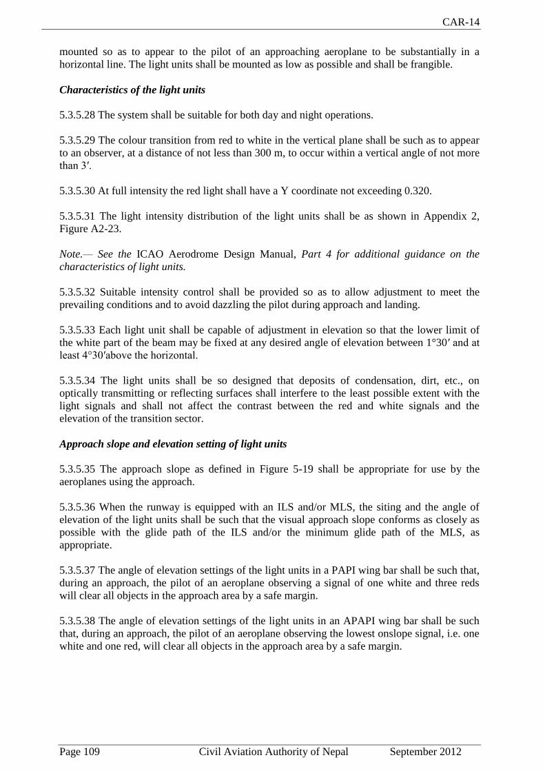
CAR-14
Page 109 Civil Aviation Authority of Nepal September 2012
mounted so as to appear to the pilot of an approaching aeroplane to be substantially in a
horizontal line. The light units shall be mounted as low as possible and shall be frangible.
Characteristics of the light units
5.3.5.28 The system shall be suitable for both day and night operations.
5.3.5.29 The colour transition from red to white in the vertical plane shall be such as to appear
to an observer, at a distance of not less than 300 m, to occur within a vertical angle of not more
than 3′.
5.3.5.30 At full intensity the red light shall have a Y coordinate not exceeding 0.320.
5.3.5.31 The light intensity distribution of the light units shall be as shown in Appendix 2,
Figure A2-23.
Note.— See the ICAO Aerodrome Design Manual, Part 4 for additional guidance on the
characteristics of light units.
5.3.5.32 Suitable intensity control shall be provided so as to allow adjustment to meet the
prevailing conditions and to avoid dazzling the pilot during approach and landing.
5.3.5.33 Each light unit shall be capable of adjustment in elevation so that the lower limit of
the white part of the beam may be fixed at any desired angle of elevation between 1°30′ and at
least 4°30′above the horizontal.
5.3.5.34 The light units shall be so designed that deposits of condensation, dirt, etc., on
optically transmitting or reflecting surfaces shall interfere to the least possible extent with the
light signals and shall not affect the contrast between the red and white signals and the
elevation of the transition sector.
Approach slope and elevation setting of light units
5.3.5.35 The approach slope as defined in Figure 5-19 shall be appropriate for use by the
aeroplanes using the approach.
5.3.5.36 When the runway is equipped with an ILS and/or MLS, the siting and the angle of
elevation of the light units shall be such that the visual approach slope conforms as closely as
possible with the glide path of the ILS and/or the minimum glide path of the MLS, as
appropriate.
5.3.5.37 The angle of elevation settings of the light units in a PAPI wing bar shall be such that,
during an approach, the pilot of an aeroplane observing a signal of one white and three reds
will clear all objects in the approach area by a safe margin.
5.3.5.38 The angle of elevation settings of the light units in an APAPI wing bar shall be such
that, during an approach, the pilot of an aeroplane observing the lowest onslope signal, i.e. one
white and one red, will clear all objects in the approach area by a safe margin.
CAR-14
Page 110 Civil Aviation Authority of Nepal September 2012

CAR-14
Page 111 Civil Aviation Authority of Nepal September 2012
5.3.5.39 The azimuth spread of the light beam shall be suitably restricted where an object
located outside the obstacle protection surface of the PAPI or APAPI system, but within the
lateral limits of its light beam, is found to extend above the plane of the obstacle protection
surface and an aeronautical study indicates that the object could adversely affect the safety of
operations. The extent of the restriction shall be such that the object remains outside the
confines of the light beam.

CAR-14
Page 112 Civil Aviation Authority of Nepal September 2012
Note.— See 5.3.5.41 to 5.3.5.45 concerning the related obstacle protection surface.
5.3.5.40 Where wing bars are installed on each side of the runway to provide roll guidance,
corresponding units shall be set at the same angle so that the signals of each wing bar change
symmetrically at the same time.
Obstacle protection surface
Note.— The following specifications apply to T-VASIS, AT-VASIS, PAPI and APAPI.
5.3.5.41 An obstacle protection surface shall be established when it is intended to provide a
visual approach slope indicator system.
5.3.5.42 The characteristics of the obstacle protection surface, i.e. origin, divergence, length
and slope shall correspond to those specified in the relevant column of Table 5-3 and in Figure
5-21.
5.3.5.43 New objects or extensions of existing objects shall not be permitted above an obstacle
protection surface except when, in the opinion of the Director General of Civil Aviation
Authority of Nepal, the new object or extension would be shielded by an existing immovable
object.
Note.— Circumstances in which the shielding principle may reasonably be applied are
described in the Airport Services Manual, Part 6.
5.3.5.44 Existing objects above an obstacle protection surface shall be removed except when,
in the opinion of the Director General of Civil Aviation Authority of Nepal, the object is
shielded by an existing immovable object, or after aeronautical study it is determined that the
object would not adversely affect the safety of operations of aeroplanes.
5.3.5.45 Where an aeronautical study indicates that an existing object extending above an
obstacle protection surface could adversely affect the safety of operations of aeroplanes one or
more of the following measures shall be taken:
a) suitably raise the approach slope of the system;
b) reduce the azimuth spread of the system so that the object is outside the confines of
the beam;
c) displace the axis of the system and its associated obstacle protection surface by no
more than 5°;
d) suitably displace the threshold; and
e) where d) is found to be impracticable, suitably displace the system upwind of the
threshold to provide an increase in threshold crossing height equal to the height of
the object penetration.
Note.— Guidance on this issue is contained in the ICAO Aerodrome Design Manual, Part 4.

CAR-14
Page 113 Civil Aviation Authority of Nepal September 2012

CAR-14
Page 114 Civil Aviation Authority of Nepal September 2012
5.3.6 Circling guidance lights
Application
5.3.6.1 Recommendation.— Circling guidance lights should be provided when existing
approach and runway lighting systems do not satisfactorily permit identification of the runway
and/or approach area to a circling aircraft in the conditions for which it is intended the
runway be used for circling approaches.
Location
5.3.6.2 Recommendation.— The location and number of circling guidance lights should be
adequate to enable a pilot, as appropriate, to:
a) join the downwind leg or align and adjust the aircraft’s track to the runway at a
required distance from it and to distinguish the threshold in passing; and
b) keep in sight the runway threshold and/or other features which will make it possible
to judge the turn on to base leg and final approach, taking into account the
guidance provided by other visual aids.

CAR-14
Page 115 Civil Aviation Authority of Nepal September 2012
5.3.6.3 Recommendation.— The Circling guidance lights should consist of:
a) lights indicating the extended centre line of the runway and/or parts of any
approach lighting system; or
b) lights indicating the position of the runway threshold; or
c) lights indicating the direction or location of the runway; or a combination of such
lights as is appropriate to the runway under consideration.
Note.— Guidance on installation of circling guidance lights is given in the ICAO
Aerodrome Design Manual, Part 4.
Characteristics
5.3.6.4 Recommendation.— Circling guidance lights should be fixed or flashing lights of an
intensity and beam spread adequate for the conditions of visibility and ambient light in which
it is intended to make visual circling approaches. The flashing lights should be white, and the
steady lights either white or gaseous discharge lights.
5.3.6.5 Recommendation.— The lights should be designed and be installed in such a manner
that they will not dazzle or confuse a pilot when approaching to land, taking off or taxiing.
5.3.7 Runway lead-in lighting systems
Application
5.3.7.1 Recommendation.— A runway lead-in lighting system should be provided where it is
desired to provide visual guidance along a specific approach path, for reasons such as
avoiding hazardous terrain or for purposes of noise abatement.
Note.— Guidance on providing lead-in lighting systems is given in the ICAO Aerodrome
Design Manual, Part 4.
Location
5.3.7.2 Recommendation.— A runway lead-in lighting system should consist of groups of
lights positioned so as to define the desired approach path and so that one group may be
sighted from the preceding group. The interval between adjacent groups should not exceed
approximately 1 600 m.
Note.— Runway lead-in lighting systems may be curved, straight or a combination thereof.
5.3.7.3 Recommendation.— A runway lead-in lighting system should extend from a point as
determined by the appropriate authority, up to a point where the approach lighting system, if
provided, or the runway or the runway lighting system is in view.
Characteristics
5.3.7.4 Recommendation.— Each group of lights of a runway lead-in lighting system should
consist of at least three flashing lights in a linear or cluster configuration. The system may be
augmented by steady burning lights where such lights would assist in identifying the system.
5.3.7.5 Recommendation.— The flashing lights should be white, and the steady burning lights
gaseous discharge lights.

CAR-14
Page 116 Civil Aviation Authority of Nepal September 2012
5.3.7.6 Recommendation.— Where practicable, the flashing lights in each group should flash
in sequence towards the runway.
5.3.8 Runway threshold identification lights
Application
5.3.8.1 Recommendation.— The runway threshold identification lights should be installed:
a) at the threshold of a non-precision approach runway when additional threshold
conspicuity is necessary or where it is not practicable to provide other approach
lighting aids; and
b) where a runway threshold is permanently displaced from the runway extremity or
temporarily displaced from the normal position and additional threshold
conspicuity is necessary.
Location
5.3.8.2 Runway threshold identification lights shall be located symmetrically about the runway
centre line, in line with the threshold and approximately 10 m outside each line of runway edge
lights.
Characteristics
5.3.8.3 Recommendation.— Runway threshold identification lights should be flashing white
lights with a flash frequency between 60 and 120 per minute.
5.3.8.4 The lights shall be visible only in the direction of approach to the runway.
5.3.9 Runway edge lights
Application
5.3.9.1 Runway edge lights shall be provided for a runway intended for use at night or for a
precision approach runway intended for use by day or night.
5.3.9.2 Recommendation.— Runway edge lights should be provided on a runway intended for
take-off with an operating minimum below an RVR of the order of 800 m by day.
Location
5.3.9.3 Runway edge lights shall be placed along the full length of the runway and shall be in
two parallel rows equidistant from the centre line.
5.3.9.4 Runway edge lights shall be placed along the edges of the area declared for use as the
runway or outside the edges of the area at a distance of not more than 3 m.

CAR-14
Page 117 Civil Aviation Authority of Nepal September 2012
5.3.9.5 Recommendation.— Where the width of the area which could be declared as runway
exceeds 60 m, the distance between the rows of lights should be determined taking into account
the nature of the operations, the light distribution characteristics of the runway edge lights,
and other visual aids serving the runway.
5.3.9.6 The lights shall be uniformly spaced in rows at intervals of not more than 60 m for an
instrument runway, and at intervals of not more than 100 m for a non-instrument runway. The
lights on opposite sides of the runway axis shall be on lines at right angles to that axis. At
intersections of runways, lights may be spaced irregularly or omitted, provided that adequate
guidance remains available to the pilot.
Characteristics
5.3.9.7 Runway edge lights shall be fixed lights showing variable white, except that:
a) in the case of a displaced threshold, the lights between the beginning of the runway
and the displaced threshold shall show red in the approach direction; and
b) a section of the lights 600 m or one-third of the runway length, whichever is the
less, at the remote end of the runway from the end at which the take-off run is
started, may show yellow.
5.3.9.8 The runway edge lights shall show at all angles in azimuth necessary to provide
guidance to a pilot landing or taking off in either direction. When the runway edge lights are
intended to provide circling guidance, they shall show at all angles in azimuth (see 5.3.6.1).
5.3.9.9 In all angles of azimuth required in 5.3.9.8, runway edge lights shall show at angles up
to 15° above the horizontal with an intensity adequate for the conditions of visibility and
ambient light in which use of the runway for take-off or landing is intended. In any case, the
intensity shall be at least 50 cd except that at an aerodrome without extraneous lighting the
intensity of the lights may be reduced to not less than 25 cd to avoid dazzling the pilot.
5.3.9.10 Runway edge lights on a precision approach runway shall be in accordance with the
specifications of Appendix 2, Figure A2-9 or A2-10.
5.3.10 Runway threshold and wing bar lights. (see Figure 5-22)
Application of runway threshold lights
5.3.10.1 Runway threshold lights shall be provided for a runway equipped with runway edge
lights except on a non instrument or non-precision approach runway where the threshold is
displaced and wing bar lights are provided.
Location of runway threshold lights
5.3.10.2 When a threshold is at the extremity of a runway, the threshold lights shall be placed
in a row at right angles to the runway axis as near to the extremity of the runway as possible
and, in any case, not more than 3 m outside the extremity.
5.3.10.3 When a threshold is displaced from the extremity of a runway, threshold lights shall
be placed in a row at right angles to the runway axis at the displaced threshold.
5.3.10.4 Threshold lighting shall consist of:
CAR-14
Page 118 Civil Aviation Authority of Nepal September 2012
a) on a non-instrument or non-precision approach runway, at least six lights;
b) on a precision approach runway category I, at least the number of lights that would
be required if the lights were uniformly spaced at intervals of 3 m between the rows
of runway edge lights; and
c) on a precision approach runway category II or III, lights uniformly spaced between
the rows of runway edge lights at intervals of not more than 3 m.
5.3.10.5 Recommendation.— The lights prescribed in 5.3.10.4 a) and b) should be either:
a) equally spaced between the rows of runway edge lights, or
b) symmetrically disposed about the runway centre line in two groups, with the lights
uniformly spaced in each group and with a gap between the groups equal to the
gauge of the touchdown zone marking or lighting, where such is provided, or
otherwise not more than half the distance between the rows of runway edge lights.
Application of wing bar lights
5.3.10.6 Recommendation.— Wing bar lights should be provided on a precision approach
runway when additional conspicuity is considered desirable.
5.3.10.7 Wing bar lights shall be provided on a non-instrument or non-precision approach
runway where the threshold is displaced and runway threshold lights are required, but are not
provided.
Location of wing bar lights
5.3.10.8 Wing bar lights shall be symmetrically disposed about the runway centre line at the
threshold in two groups, i.e. wing bars. Each wing bar shall be formed by at least five lights
extending at least 10 m outward from, and at right angles to, the line of the runway edge lights,
with the innermost light of each wing bar in the line of the runway edge lights.
Characteristics of runway threshold and wing bar lights
5.3.10.9 Runway threshold and wing bar lights shall be fixed unidirectional lights showing
green in the direction of approach to the runway. The intensity and beam spread of the lights
shall be adequate for the conditions of visibility and ambient light in which use of the runway
is intended.

CAR-14
Page 119 Civil Aviation Authority of Nepal September 2012
CAR-14
Page 120 Civil Aviation Authority of Nepal September 2012
5.3.10.10 Runway threshold lights on a precision approach runway shall be in accordance with the
specifications of Appendix 2, Figure A2-3.
5.3.10.11 Threshold wing bar lights on a precision approach runway shall be in accordance with the
specifications of Appendix 2, Figure A2-4.
5.3.11 Runway end lights (see Figure 5-22)
Application
5.3.11.1 Runway end lights shall be provided for a runway equipped with runway edge lights.
Note.— When the threshold is at the runway extremity, fittings serving as threshold lights may be used as
runway end lights.
Location
5.3.11.2 Runway end lights shall be placed on a line at right angles to the runway axis as near to the end
of the runway as possible and, in any case, not more than 3 m outside the end.
5.3.11.3 Recommendation.— Runway end lighting should consist of at least six lights. The lights should
be either:
a) equally spaced between the rows of runway edge lights, or
b) symmetrically disposed about the runway centre line in two groups with the lights uniformly
spaced in each group and with a gap between the groups of not more than half the distance
between the rows of runway edge lights.
For a precision approach runway category III, the spacing between runway end lights, except between
the two innermost lights if a gap is used, should not exceed 6 m.
Characteristics
5.3.11.4 Runway end lights shall be fixed unidirectional lights showing red in the direction of the
runway. The intensity and beam spread of the lights shall be adequate for the conditions of visibility and
ambient light in which use of the runway is intended.
5.3.11.5 Runway end lights on a precision approach runway shall be in accordance with the
specifications of Appendix 2, Figure A2-8.

CAR-14
Page 121 Civil Aviation Authority of Nepal September 2012
5.3.12 Runway centre line lights
Application
5.3.12.1 Runway centre line lights shall be provided on a precision approach runway category II or III.
5.3.12.2 Recommendation.— Runway centre line lights should be provided on a precision approach
runway category I, particularly when the runway is used by aircraft with high landing speeds or where
the width between the runway edge lights is greater than 50 m.
5.3.12.3 Runway centre line lights shall be provided on a runway intended to be used for take-off with an
operating minimum below an RVR of the order of 400 m.
5.3.12.4 Recommendation.— Runway centre line lights should be provided on a runway intended to be
used for take-off with an operating minimum of an RVR of the order of 400 m or higher when used by
aeroplanes with a very high take-off speed, particularly where the width between the runway edge lights
is greater than 50 m.
Location
5.3.12.5 Runway centre line lights shall be located along the centre line of the runway, except that the
lights may be uniformly offset to the same side of the runway centre line by not more than 60 cm where
it is not practicable to locate them along the centre line. The lights shall be located from the threshold to
the end at longitudinal spacing of approximately 15 m. Where the serviceability level of the runway
centre line lights specified as maintenance objectives in 10.4.7 or 10.4.11, as appropriate, can be
demonstrated and the runway is intended for use in runway visual range conditions of 350 m or greater,
the longitudinal spacing may be approximately 30 m.
Note.— Existing centre line lighting where lights are spaced at 7.5 m need not be replaced.
5.3.12.6 Recommendation.— Centre line guidance for take-off from the beginning of a runway to a
displaced threshold should be provided by:
a) an approach lighting system if its characteristics and intensity settings afford the guidance
required during take-off and it does not dazzle the pilot of an aircraft taking off; or
b) runway centre line lights; or
c) barrettes of at least 3 m length and spaced at uniform intervals of 30 m, as shown in Figure
5-22, designed so that their photometric characteristics and intensity setting afford the
guidance required during take-off without dazzling the pilot of an aircraft taking off.
Where necessary, provision should be made to extinguish those centre line lights specified in b) or reset
the intensity of the approach lighting system or barrettes when the runway is being used for landing. In
no case should only the single source runway centre line lights show from the beginning of the runway to
a displaced threshold when the runway is being used for landing.

CAR-14
Page 122 Civil Aviation Authority of Nepal September 2012
Characteristics
5.3.12.7 Runway centre line lights shall be fixed lights showing variable white from the threshold to the
point 900 m from the runway end; alternate red and variable white from 900 m to 300 m from the
runway end; and red from 300 m to the runway end, except that for runways less than 1 800 m in length,
the alternate red and variable white lights shall extend from the mid-point of the runway usable for
landing to 300 m from the runway end.
Note.— Care is required in the design of the electrical system to ensure that failure of part of the
electrical system will not result in a false indication of the runway distance remaining.
5.3.12.8 Runway centre line lights shall be in accordance with the specifications of Appendix 2, Figure
A2-6 or A2-7.
5.3.13 Runway touchdown zone lights
Application
5.3.13.1 Touchdown zone lights shall be provided in the touchdown zone of a precision approach
runway category II or III.
Location
5.3.13.2 Touchdown zone lights shall extend from the threshold for a longitudinal distance of 900 m,
except that, on runways less than 1 800 m in length, the system shall be shortened so that it does not
extend beyond the midpoint of the runway. The pattern shall be formed by pairs of barrettes
symmetrically located about the runway centre line. The lateral spacing between the innermost lights of a
pair of barrettes shall be equal to the lateral spacing selected for the touchdown zone marking. The
longitudinal spacing between pairs of barrettes shall be either 30 m or 60 m.
Note.— To allow for operations at lower visibility minima, it may be advisable to use a 30 m
longitudinal spacing between barrettes.
Characteristics
5.3.13.3 A barrette shall be composed of at least three lights with a spacing between the lights of not
more than 1.5 m.
5.3.13.4 Recommendation.— A barrette should be not less than 3 m nor more than 4.5 m in length.
5.3.13.5 Touchdown zone lights shall be fixed unidirectional lights showing variable white.
5.3.13.6 Touchdown zone lights shall be in accordance with the specifications of Appendix 2, Figure A2-
5.

CAR-14
Page 123 Civil Aviation Authority of Nepal September 2012
5.3.14 Rapid exit taxiway indicator lights
Note.— The purpose of rapid exit taxiway indicator lights (RETILs) is to provide pilots with distance-to-
go information to the nearest rapid exit taxiway on the runway, to enhance situational awareness in low
visibility conditions and enable pilots to apply braking action for more efficient roll-out and runway exit
speeds. It is essential that pilots operating at aerodromes with runway(s) displaying rapid exit taxiway
indicator lights be familiar with the purpose of these lights.
Application
5.3.14.1 Recommendation.— Rapid exit taxiway indicator lights should be provided on a runway
intended for use in runway visual range conditions less than a value of 350 m and/or where the traffic
density is heavy.
Note.— See Attachment A, Section 14.
5.3.14.2 Rapid exit taxiway indicator lights shall not be displayed in the event of any lamp failure or
other failure that prevents the display of the light pattern depicted in Figure 5-24, in full.

CAR-14
Page 124 Civil Aviation Authority of Nepal September 2012
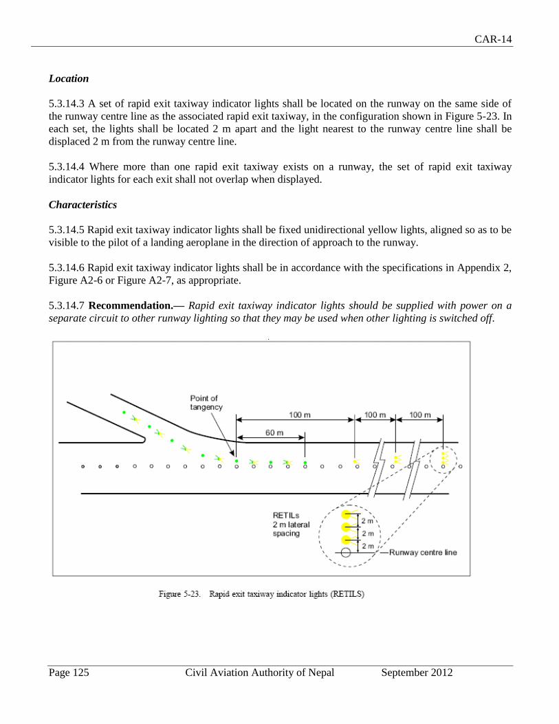
CAR-14
Page 125 Civil Aviation Authority of Nepal September 2012
Location
5.3.14.3 A set of rapid exit taxiway indicator lights shall be located on the runway on the same side of
the runway centre line as the associated rapid exit taxiway, in the configuration shown in Figure 5-23. In
each set, the lights shall be located 2 m apart and the light nearest to the runway centre line shall be
displaced 2 m from the runway centre line.
5.3.14.4 Where more than one rapid exit taxiway exists on a runway, the set of rapid exit taxiway
indicator lights for each exit shall not overlap when displayed.
Characteristics
5.3.14.5 Rapid exit taxiway indicator lights shall be fixed unidirectional yellow lights, aligned so as to be
visible to the pilot of a landing aeroplane in the direction of approach to the runway.
5.3.14.6 Rapid exit taxiway indicator lights shall be in accordance with the specifications in Appendix 2,
Figure A2-6 or Figure A2-7, as appropriate.
5.3.14.7 Recommendation.— Rapid exit taxiway indicator lights should be supplied with power on a
separate circuit to other runway lighting so that they may be used when other lighting is switched off.

CAR-14
Page 126 Civil Aviation Authority of Nepal September 2012
5.3.15 Stopway lights
Application
5.3.15.1 Stopway lights shall be provided for a stopway intended for use at night
Location
5.3.15.2 Stopway lights shall be placed along the full length of the stopway and shall be in two parallel
rows that are equidistant from the centre line and coincident with the rows of the runway edge lights.
Stopway lights shall also be provided across the end of a stopway on a line at right angles to the stopway
axis as near to the end of the stopway as possible and, in any case, not more than 3 m outside the end.
Characteristics
5.3.15.3 Stopway lights shall be fixed unidirectional lights showing red in the direction of the runway.
5.3.16 Taxiway centre line lights
Application
5.3.16.1 Taxiway centre line lights shall be provided on an exit taxiway, taxiway and apron intended for
use in runway visual range conditions less than a value of 350 m in such a manner as to provide
continuous guidance between the runway centre line and aircraft stands, except that these lights need not
be provided where the traffic density is light and taxiway edge lights and centre line marking provide
adequate guidance.
5.3.16.2 Recommendation.— Taxiway centre line lights should be provided on a taxiway intended for
use at night in runway visual range conditions of 350 m or greater, and particularly on complex taxiway
intersections and exit taxiways, except that these lights need not be provided where the traffic density is
light and taxiway edge lights and centre line marking provide adequate guidance.
Note.— Where there may be a need to delineate the edges of a taxiway, e.g. on a rapid exit taxiway,
narrow taxiway, this may be done with taxiway edge lights or markers.
5.3.16.3 Recommendation.— Taxiway centre line lights should be provided on an exit taxiway, taxiway
and apron in all visibility conditions where specified as components of an advanced surface movement
guidance and control system in such a manner as to provide continuous guidance between the runway
centre line and aircraft stands.
5.3.16.4 Taxiway centre line lights shall be provided on a runway forming part of a standard taxi-route
and intended for taxiing in runway visual range conditions less than a value of 350 m, except that these
lights need not be provided where the traffic density is light and taxiway edge lights and centre line
marking provide adequate guidance.
Note.— See 8.2.3 for provisions concerning the interlocking of runway and taxiway lighting systems.
CAR-14
Page 127 Civil Aviation Authority of Nepal September 2012
5.3.16.5 Recommendation.— Taxiway centre line lights should be provided in all visibility conditions
on a runway forming part of a standard taxi-route where specified as components of an advanced
surface movement guidance and control system.
Characteristics
5.3.16.6 Taxiway centre line lights on a taxiway other than an exit taxiway and on a runway forming part
of a standard taxi-route shall be fixed lights showing green with beam dimensions such that the light is
visible only from aeroplanes on or in the vicinity of the taxiway.
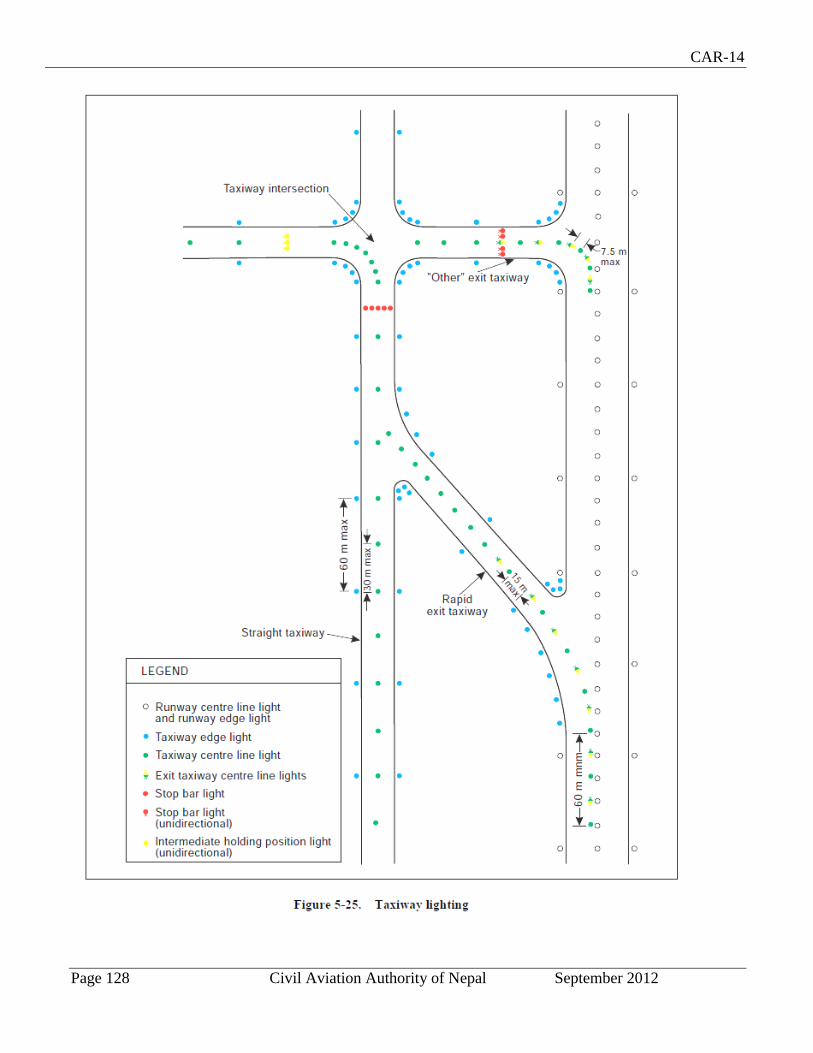
CAR-14
Page 128 Civil Aviation Authority of Nepal September 2012
CAR-14
Page 129 Civil Aviation Authority of Nepal September 2012
5.3.16.7 Taxiway centre line lights on an exit taxiway shall be fixed lights. Alternate taxiway centre line
lights shall show green and yellow from their beginning near the runway centre line to the perimeter of
the ILS/MLS critical/sensitive area or the lower edge of the inner transitional surface, whichever is
farthest from the runway; and thereafter all lights shall show green (Figure 5-24). The light nearest to the
perimeter shall always show yellow. Where aircraft may follow the same centre line in both directions,
all the centre line lights shall show green to aircraft approaching the runway.
Note 1.— Care is necessary to limit the light distribution of green lights on or near a runway so as to
avoid possible confusion with threshold lights.
Note 2.— For yellow filter characteristics see Appendix 1, 2.2.
Note 3.— The size of the ILS/MLS critical/sensitive area depends on the characteristics of the associated
ILS/MLS and other factors. Guidance is provided in Annex 10, Part 1, Attachments C and G.
Note 4.— See 5.4.3 for specifications on runway vacated signs.
5.3.16.8 Taxiway centre line lights shall be in accordance with the specifications of:
a) Appendix 2, Figure A2-12, A2-13, or A2-14 for taxiways intended for use in runway visual
range conditions of less than a value of 350 m; and
b) Appendix 2, Figure A2-15 or A2-16 for other taxiways.
5.3.16.9 Recommendation.— Where higher intensities are required, from an operational point of view,
taxiway centre line lights on rapid exit taxiways intended for use in runway visual range conditions less
than a value of 350 m should be in accordance with the specifications of Appendix 2, Figure A2-12. The
number of levels of brilliancy settings for these lights should be the same as that for the runway centre
line lights.
5.3.16.10 Recommendation.— Where taxiway centre line lights are specified as components of an
advanced surface movement guidance and control system and where, from an operational point of view,
higher intensities are required to maintain ground movements at a certain speed in very low visibilities
or in bright daytime conditions, taxiway centre line lights should be in accordance with the
specifications of Appendix 2, Figure A2-17, A2-18 or A2-19.
Note.— High-intensity centre line lights should only be used in case of an absolute necessity and
following a specific study.
Location
5.3.16.11 Recommendation.— Taxiway centre line lights should normally be located on the taxiway
centre line marking, except that they may be offset by not more than 30 cm where it is not practicable to
locate them on the marking.

CAR-14
Page 130 Civil Aviation Authority of Nepal September 2012
Taxiway centre line lights on taxiways
Location
5.3.16.12 Recommendation.— Taxiway centre line lights on a straight section of a taxiway should be
spaced at longitudinal intervals of not more than 30 m, except that:
a) larger intervals not exceeding 60 m may be used where, because of the prevailing
meteorological conditions, adequate guidance is provided by such spacing;
b) intervals less than 30 m should be provided on short straight sections; and
c) on a taxiway intended for use in RVR conditions of less than a value of 350 m, the
longitudinal spacing should not exceed 15 m.
5.3.16.13 Recommendation.— Taxiway centre line lights on a taxiway curve should continue from the
straight portion of the taxiway at a constant distance from the outside edge of the taxiway curve. The
lights should be spaced at intervals such that a clear indication of the curve is provided.
5.3.16.14 Recommendation.— On a taxiway intended for use in RVR conditions of less than a value of
350 m, the lights on a curve should not exceed a spacing of 15 m and on a curve of less than 400 m
radius the lights should be spaced at intervals of not greater than 7.5 m. This spacing should extend for
60 m before and after the curve.
Note 1.— Spacings on curves that have been found suitable for a taxiway intended for use in RVR
conditions of 350 m or greater are:
Curve radius Light spacing
up to 400 m 7.5 m
401 m to 899 m 15 m
900 m or greater 30 m
Note 2.— See 3.9.6 and Figure 3-2.
Taxiway centre line lights on rapid exit taxiways
Location
5.3.16.15 Taxiway centre line lights on a rapid exit taxiway shall commence at a point at least 60 m
before the beginning of the taxiway centre line curve and continue beyond the end of the curve to a point
on the centre line of the taxiway where an aeroplane can be expected to reach normal taxiing speed. The
lights on that portion parallel to the runway centre line should always be at least 60 cm from any row of
runway centre line lights, as shown in Figure 5-25.

CAR-14
Page 131 Civil Aviation Authority of Nepal September 2012
5.3.16.16 The lights shall be spaced at longitudinal intervals of not more than 15 m, except that, where
runway centre line lights are not provided, a greater interval not exceeding 30 m may be used.
Taxiway centre line lights on other exit taxiways
Location
5.3.16.17 Recommendation.— Taxiway centre line lights on exit taxiways other than rapid exit
taxiways should commence at the point where the taxiway centre line marking begins to curve from the
runway centre line, and follow the curved taxiway centre line marking at least to the point where the
marking leaves the runway. The first light should be at least 60 cm from any row of runway centre line
lights, as shown in Figure 5-25.
5.3.16.18 Recommendation.— Lights shall be spaced at longitudinal intervals of not more than 7.5 m.
Taxiway centre line lights on runways
Location
5.3.16.19 Recommendation.— Taxiway centre line lights on a runway forming part of a standard taxi-
route and intended for taxiing in runway visual range conditions less than a value of 350 m should be
spaced at longitudinal intervals not exceeding 15 m.

CAR-14
Page 132 Civil Aviation Authority of Nepal September 2012
5.3.17 Taxiway edge lights
Application
5.3.17.1 Taxiway edge lights shall be provided at the edges of a runway turn pad, holding bay, apron,
etc. intended for use at night and on a taxiway not provided with taxiway centre line lights and intended
for use at night, except that taxiway edge lights need not be provided where, considering the nature of
the operations, adequate guidance can be achieved by surface illumination or other means.
Note.— See 5.5.5 for taxiway edge markers.
5.3.17.2 Taxiway edge lights shall be provided on a runway forming part of a standard taxi-route and
intended for taxiing at night where the runway is not provided with taxiway centre line lights.
Note.— See 8.2.3 for provisions concerning the inter-locking of runway and taxiway lighting systems.
Location
5.3.17.3 Recommendation.— Taxiway edge lights on a straight section of a taxiway and on a runway
forming part of a standard taxi-route should be spaced at uniform longitudinal intervals of not more
CAR-14
Page 133 Civil Aviation Authority of Nepal September 2012
than 60 m. The lights on a curve should be spaced at intervals less than 60 m so that a clear indication of
the curve is provided.
Note.— Guidance on the spacing of taxiway edge lights on curves is given in the Aerodrome Design
Manual, Part 4.
5.3.17.4 Recommendation.— Taxiway edge lights on a holding bay, apron, etc. should be spaced at
uniform longitudinal intervals of not more than 60 m.
5.3.17.5 Recommendation.— Taxiway edge lights on a runway turn pad should be spaced at uniform
longitudinal intervals of not more than 30 m.
5.3.17.6 Recommendation.— The lights should be located as near as practicable to the edges of the
taxiway, runway turn pad, holding bay, apron or runway, etc. or outside the edges at a distance of not
more than 3 m.
Characteristics
5.3.17.7 Taxiway edge lights shall be fixed lights showing blue. The lights shall show up to at least 75°
above the horizontal and at all angles in azimuth necessary to provide guidance to a pilot taxiing in either
direction. At an intersection, exit or curve the lights shall be shielded as far as practicable so that they
cannot be seen in angles of azimuth in which they may be confused with other lights.
5.3.17.8 The intensity of taxiway edge lights shall be at least 2 cd from 0° to 6° vertical, and 0.2 cd at
any vertical angles between 6° and 75°.
5.3.18 Runway turn pad lights
Application
5.3.18.1 Runway turn pad lights shall be provided for continuous guidance on a runway turn pad
intended for use in runway visual range conditions less than a value of 350 m, to enable an aeroplane to
complete a 180-degree turn and align with the runway centre line.
5.3.18.2 Recommendation.— Runway turn pad lights should be provided on a runway turn pad
intended for use at night.
Location
5.3.18.3 Recommendation.— Runway turn pad lights should normally be located on the runway turn
pad marking, except that they may be offset by not more than 30 cm where it is not practicable to locate
them on the marking.
5.3.18.4 Recommendation.— Runway turn pad lights on a straight section of the runway turn pad
marking should be spaced at longitudinal intervals of not more than 15 m.
5.3.18.5 Recommendation.— Runway turn pad lights on a curved section of the runway turn pad
marking should not exceed a spacing of 7.5 m.
CAR-14
Page 134 Civil Aviation Authority of Nepal September 2012
Characteristics
5.3.18.6 Runway turn pad lights shall be unidirectional fixed lights showing green with beam dimensions
such that the light is visible only from aeroplanes on or approaching the runway turn pad.
5.3.18.7 Runway turn pad lights shall be in accordance with the specifications of Appendix 2, Figure A2-
13, A2-14 or A2-15, as appropriate.
5.3.19 Stop bars
Application
Note 1.— The provision of stop bars requires their control either manually or automatically by air traffic
services.
Note 2.— Runway incursions may take place in all visibility or weather conditions. The provision of stop
bars at runway holding positions and their use at night and in visibility conditions greater than 550 m
runway visual range can form part of effective runway incursion prevention measures.
5.3.19.1 A stop bar shall be provided at every runway-holding position serving a runway when it is
intended that the runway will be used in runway visual range conditions less than a value of 350 m,
except where:
a) appropriate aids and procedures are available to assist in preventing inadvertent incursions of
aircraft and vehicles onto the runway; or
b) operational procedures exist to limit, in runway visual range conditions less than a value of
550 m, the number of:
1) aircraft on the manoeuvring area to one at a time; and
2) vehicles on the manoeuvring area to the essential minimum.
5.3.19.2 A stop bar shall be provided at every runway holding position, serving a runway when it is
intended that the runway will be used in runway visual range conditions of values between 350 m and
550 m, except where:
a) appropriate aids and procedures are available to assist in preventing inadvertent incursions of
aircraft and vehicles onto the runway; or
b) operational procedures exist to limit, in runway visual range conditions less than a value of
550 m, the number of:
1) aircraft on the manoeuvring area to one at a time; and
2) vehicles on the manoeuvring area to the essential minimum.

CAR-14
Page 135 Civil Aviation Authority of Nepal September 2012
5.3.19.3 Recommendation.— A stop bar should be provided at an intermediate holding position when it
is desired to supplement markings with lights and to provide traffic control by visual means.
5.3.19.4 Recommendation.— Where the normal stop bar lights might be obscured (from a pilot’s view),
for example, by rain, or where a pilot may be required to stop the aircraft in a position so close to the
lights that they are blocked from view by the structure of the aircraft, then a pair of elevated lights
should be added to each end of the stop bar.
Location
5.3.19.5 Stop bars shall be located across the taxiway at the point where it is desired that traffic stop.
Where the additional lights specified in 5.3.19.4 are provided, these lights shall be located not less than 3
m from the taxiway edge.
Characteristics
5.3.19.6 Stop bars shall consist of lights spaced at intervals of 3 m across the taxiway, showing red in the
intended direction(s) of approach to the intersection or runway-holding position.
5.3.19.7 Stop bars installed at a runway-holding position shall be unidirectional and shall show red in the
direction of approach to the runway.
5.3.19.8 Where the additional lights specified in 5.3.19.4 are provided, these lights shall have the same
characteristics as the lights in the stop bar, but shall be visible to approaching aircraft up to the stop bar
position.
5.3.19.9 Selectively switchable stop bars shall be installed in conjunction with at least three taxiway
centre line lights (extending for a distance of at least 90 m from the stop bar) in the direction that it is
intended for an aircraft to proceed from the stop bar.
Note.— See 5.3.16.12 for provisions concerning the spacing of taxiway centre line lights.
5.3.19.10 The intensity in red light and beam spreads of stop bar lights shall be in accordance with the
specifications in Appendix 2, Figures A2-12 through A2-16, as appropriate.
5.3.19.11 Recommendation.— Where stop bars are specified as components of an advanced surface
movement guidance and control system and where, from an operational point of view, higher intensities
are required to maintain ground movements at a certain speed in very low visibilities or in bright
daytime conditions, the intensity in red light and beam spreads of stop bar lights should be in
accordance with the specifications of Appendix 2, Figure A2-17, A2-18 or A2-19.
Note.— High-intensity stop bars should only be used in case of an absolute necessity and following a
specific study.
5.3.19.12 Recommendation.— Where a wide beam fixture is required, the intensity in red light and
beam spreads of stop bar lights should be in accordance with the specifications of Appendix 2, Figure
A2-17 or A2-19.

CAR-14
Page 136 Civil Aviation Authority of Nepal September 2012
5.3.19.13 The lighting circuit shall be designed so that:
a) stop bars located across entrance taxiways are selectively switchable;
b) stop bars located across taxiways intended to be used only as exit taxiways are switchable
selectively or in groups;
b) when a stop bar is illuminated, any taxiway centre line lights installed beyond the stop bar
shall be extinguished for a distance of at least 90 m; and
c) stop bars shall be interlocked with the taxiway centre line lights so that when the centre line
lights beyond the stop bar are illuminated the stop bar is extinguished and vice versa.
Note 1.— A stop bar is switched on to indicate that traffic stop and switched off to indicate that traffic
proceed.
Note 2.— Care is required in the design of the electrical system to ensure that all of the lights of a stop
bar will not fail at the same time. Guidance on this issue is given in the Aerodrome Design Manual, Part
5.
5.3.20 Intermediate holding position lights
Note.— See 5.2.11 for specifications on intermediate holding position marking.
Application
5.3.20.1 Except where a stop bar has been installed, intermediate holding position lights shall be
provided at an intermediate holding position intended for use in runway visual range conditions less than
a value of 350 m.
5.3.20.2 Recommendation.— Intermediate holding position lights should be provided at an
intermediate holding position where there is no need for stop-and-go signals as provided by a stop bar.
Location
5.3.20.3 Intermediate holding position lights shall be located along the intermediate holding position
marking at a distance of 0.3 m prior to the marking.
Characteristics
5.3.20.4 Intermediate holding position lights shall consist of three fixed unidirectional lights showing
yellow in the direction of approach to the intermediate holding position with a light distribution similar
to taxiway centre line lights if provided. The lights shall be disposed symmetrically about and at right
angle to the taxiway centre line, with individual lights spaced 1.5 m apart.

CAR-14
Page 137 Civil Aviation Authority of Nepal September 2012
5.3.21 De-icing/anti-icing facility exit lights
Application
5.3.21.1 Recommendation.— De-icing/anti-icing facility exit lights should be provided at the exit
boundary of a remote de-icing/anti-icing facility adjoining a taxiway.
Location
5.3.21.2 De-icing/anti-icing facility exit lights shall be located 0.3 m inward of the intermediate holding
position marking displayed at the exit boundary of a remote de-icing/ anti-icing facility.
Characteristics
5.3.21.3 De-icing/anti-icing facility exit lights shall consist of in-pavement fixed unidirectional lights
spaced at intervals of 6 m showing yellow in the direction of the approach to the exit boundary with a
light distribution similar to taxiway centre line lights (see Figure 5-27).
5.3.22 Runway guard lights
Note.— The purpose of runway guard lights is to warn pilots, and drivers of vehicles when they are
operating on taxiways, that they are about to enter an active runway. There are two standard
configurations of runway guard lights as illustrated in Figure 5-28.
Application
5.3.22.1 Runway guard lights, Configuration A, shall be provided at each taxiway/runway intersection
associated with a runway intended for use in:
a) runway visual range conditions less than a value of 550 m where a stop bar is not installed;
and
CAR-14
Page 138 Civil Aviation Authority of Nepal September 2012
b) runway visual range conditions of values between 550 m and 1 200 m where the traffic
density is heavy.
5.3.22.2 Recommendation.— Runway guard lights, Configuration A, should be provided at each
taxiway/runway intersection associated with a runway intended for use in:
a) runway visual range conditions of values less than a value of 550 m where a stop bar is
installed; and
b) runway visual range conditions of values between 550 m and 1 200 m where the traffic density
is medium or light.
5.3.22.3 Recommendation.— Runway guard lights, Configuration A or Configuration B or both, should
be provided at each taxiway/runway intersection where enhanced conspicuity of the taxiway/runway
intersection is needed, such as on a wide-throat taxiway, except that Configuration B should not be
collocated with a stop bar.
Location
5.3.22.4 Runway guard lights, Configuration A, shall be located at each side of the taxiway at a distance
from the runway centre line not less than that specified for a take-off runway in Table 3-2.
5.3.22.5 Runway guard lights, Configuration B, shall be located across the taxiway at a distance from the
runway centre line not less than that specified for a take-off runway in Table 3-2.
Characteristics
5.3.22.6 Runway guard lights, Configuration A, shall consist of two pairs of yellow lights.
5.3.22.7 Recommendation.— Where there is a need to enhance the contrast between the on and off
state of runway guard lights, Configuration A, intended for use during the day, a visor of sufficient size
to prevent sunlight from entering the lens without interfering with the function of the fixture should be
located above each lamp.
Note.— Some other device or design, e.g. specially designed optics, may be used in lieu of the visor.
5.3.22.8 Runway guard lights, Configuration B, shall consist of yellow lights spaced at intervals of 3 m
across the taxiway.
5.3.22.9 The light beam shall be unidirectional and aligned so as to be visible to the pilot of an aeroplane
taxiing to the holding position.
5.3.22.10 Recommendation.— The intensity in yellow light and beam spreads of lights of Configuration
A should be in accordance with the specifications in Appendix 2, Figure A2-24.
5.3.22.11 Recommendation.— Where runway guard lights are intended for use during the day, the
intensity in yellow light and beam spreads of lights of Configuration A should be in accordance with the
specifications in Appendix 2, Figure A2-25.

CAR-14
Page 139 Civil Aviation Authority of Nepal September 2012
5.3.22.12 Recommendation.— Where runway guard lights are specified as components of an advanced
surface movement guidance and control system where higher light intensities are required, the intensity
in yellow light and beam spreads of lights of Configuration A should be in accordance with the
specifications in Appendix 2, Figure A2-25.
Note.— Higher light intensities may be required to maintain ground movement at a certain speed in low
visibilities.
5.3.22.13 Recommendation.— The intensity in yellow light and beam spreads of lights of Configuration
B should be in accordance with the specifications in Appendix 2, Figure A2-12.
5.3.22.14 Recommendation.— Where runway guard lights are intended for use during the day, the
intensity in yellow light and beam spreads of lights of Configuration B should be in accordance with the
specifications in Appendix 2, Figure A2-20.
5.3.22.15 Recommendation.— Where runway guard lights are specified as components of an advanced
surface movement guidance and control system where higher light intensities are required, the intensity
in yellow light and beam spreads of lights of Configuration B should be in accordance with the
specifications in Appendix 2, Figure A2-20.
5.3.22.16 The lights in each unit of Configuration A shall be illuminated alternately.
5.3.22.17 For Configuration B, adjacent lights shall be alternately illuminated and alternative lights shall
be illuminated in unison.
5.3.22.18 The lights shall be illuminated between 30 and 60 cycles per minute and the light suppression
and illumination periods shall be equal and opposite in each light.

CAR-14
Page 140 Civil Aviation Authority of Nepal September 2012
Note.— The optimum flash rate is dependent on the rise and fall times of the lamps used. Runway guard
lights, Configuration A, installed on 6.6 ampere series circuits have been found to look best when
operated at 45 to 50 flashes per minute per lamp. Runway guard lights, Configuration B, installed on 6.6
ampere series circuits have been found to look best when operated at 30 to 32 flashes per minute per
lamp.
5.3.23 Apron floodlighting
(see also 5.3.16.1 and 5.3.17.1)
Application
5.3.23.1 Recommendation.— Apron floodlighting should be provided on an apron and on a designated
isolated aircraft parking position intended to be used at night.
Note 1.— Where a de-icing/anti-icing facility is located in close proximity to the runway and permanent
floodlighting could be confusing to pilots, other means of illumination of the facility may be required.
Note 2.— The designation of an isolated aircraft parking position is specified in 3.14.
Note 3.— Guidance on apron floodlighting is given in the ICAO Aerodrome Design Manual, Part 4.
Location
5.3.23.2 Recommendation.— Apron floodlights should be located so as to provide adequate
illumination on all apron service areas, with a minimum of glare to pilots of aircraft in flight and on the
ground, aerodrome and apron controllers, and personnel on the apron. The arrangement and aiming of
floodlights should be such that an aircraft stand receives light from two or more directions to minimize
shadows.
Characteristics
5.3.23.3 The spectral distribution of apron floodlights shall be such that the colours used for aircraft
marking connected with routine servicing, and for surface and obstacle marking, can be correctly
identified.
5.3.23.4 Recommendation.— The average illuminance should be at least the following:
Aircraft stand:
- horizontal illuminance — 20 lux with a uniformity ratio (average to minimum) of not more than 4
to 1; and
- vertical illuminance — 20 lux at a height of 2 m above the apron in relevant directions.

CAR-14
Page 141 Civil Aviation Authority of Nepal September 2012
Other apron areas:
- horizontal illuminance — 50 per cent of the average illuminance on the aircraft stands with a
uniformity ratio (average to minimum) of not more than 4 to 1.
5.3.24 Visual docking guidance system
Application
5.3.24.1 A visual docking guidance system shall be provided when it is intended to indicate, by a visual
aid, the precise positioning of an aircraft on an aircraft stand and other alternative means, such as
marshallers, are not practicable.
Note.— The factors to be considered in evaluating the need for a visual docking guidance system are in
particular: the number and type(s) of aircraft using the aircraft stand, weather conditions, space
available on the apron and the precision required for manoeuvring into the parking position due to
aircraft servicing installation, passenger loading bridges, etc. See the Aerodrome Design Manual, Part
4 — Visual Aids for guidance on the selection of suitable systems.
Characteristics
5.3.24.2 The system shall provide both azimuth and stopping guidance.
5.3.24.3 The azimuth guidance unit and the stopping position indicator shall be adequate for use in all
weather, visibility, background lighting and pavement conditions for which the system is intended both
by day and night, but shall not dazzle the pilot.
Note.— Care is required in both the design and on-site installation of the system to ensure that reflection
of sunlight, or other light in the vicinity, does not degrade the clarity and conspicuity of the visual cues
provided by the system.
5.3.24.4 The azimuth guidance unit and the stopping position indicator shall be of a design such that:
a) a clear indication of malfunction of either or both is available to the pilot; and
b) they can be turned off.
5.3.24.5 The azimuth guidance unit and the stopping position indicator shall be located in such a way
that there is continuity of guidance between the aircraft stand markings, the aircraft stand manoeuvring
guidance lights, if present, and the visual docking guidance system.
5.3.24.6 The accuracy of the system shall be adequate for the type of loading bridge and fixed aircraft
servicing installations with which it is to be used.
5.3.24.7 Recommendation.— The system should be usable by all types of aircraft for which the aircraft
stand is intended, preferably without selective operation.
CAR-14
Page 142 Civil Aviation Authority of Nepal September 2012
5.3.24.8 If selective operation is required to prepare the system for use by a particular type of aircraft,
then the system shall provide an identification of the selected aircraft type to both the pilot and the
system operator as a means of ensuring that the system has been set properly.
Azimuth guidance unit
Location
5.3.24.9 The azimuth guidance unit shall be located on or close to the extension of the stand centre line
ahead of the aircraft so that its signals are visible from the cockpit of an aircraft throughout the docking
manoeuvre and aligned for use at least by the pilot occupying the left seat.
5.3.24.10 Recommendation.— The azimuth guidance unit should be aligned for use by the pilots
occupying both the left and right seats.
Characteristics
5.3.24.11 The azimuth guidance unit shall provide unambiguous left/right guidance which enables the
pilot to acquire and maintain the lead-in line without over-controlling.
5.3.24.12 When azimuth guidance is indicated by colour change, green shall be used to identify the
centre line and red for deviations from the centre line.
Stopping position indicator
Location
5.3.24.13 The stopping position indicator shall be located in conjunction with, or sufficiently close to,
the azimuth guidance unit so that a pilot can observe both the azimuth and stop signals without turning
the head.
5.3.24.14 The stopping position indicator shall be usable at least by the pilot occupying the left seat.
5.3.24.15 Recommendation.— The stopping position indicator should be usable by the pilots occupying
both the left and right seats.
Characteristics
5.3.24.16 The stopping position information provided by the indicator for a particular aircraft type shall
account for the anticipated range of variations in pilot eye height and/or viewing angle.
5.3.24.17 The stopping position indicator shall show the stopping position for the aircraft for which
guidance is being provided, and shall provide closing rate information to enable the pilot to gradually
decelerate the aircraft to a full stop at the intended stopping position.
5.3.24.18 Recommendation.— The stopping position indicator should provide closing rate information
over a distance of at least 10 m.

CAR-14
Page 143 Civil Aviation Authority of Nepal September 2012
5.3.24.19 When stopping guidance is indicated by colour change, green shall be used to show that the
aircraft can proceed and red to show that the stop point has been reached except that for a short distance
prior to the stop point a third colour may be used to warn that the stopping point is close.
5.3.25 Advanced visual docking guidance system
Application
Note 1.— Advanced visual docking guidance systems (A-VDGS) include those systems that, in addition to basic and passive azimuth and stop position information, provide pilots with active (usually sensor-based) guidance information, such as aircraft type indication (in accordance with Doc 8643 — Aircraft Type Designators,), distance-to-go information and closing speed. Docking guidance information is usually provided on a single display unit.
Note 2.— An A-VDGS may provide docking guidance information in three stages: the acquisition of the aircraft by the system, the azimuth alignment of the aircraft, and the stopping position information.
5.3.25.1 Recommendation.—An A-VDGS should be provided where it is operationally desirable to confirm the correct aircraft type for which guidance is being provided and/or to indicate the stand centre line in use, where more than one is provided for.
5.3.25.2 The A-VDGS shall be suitable for use by all types of aircraft for which the aircraft stand is intended.
5.3.25.3 The A-VDGS shall be used only in conditions in which its operational performance is specified.
Note 1.— The use of the A-VDGS in conditions such as weather, visibility and background lighting, both by day and night, would need to be specified.
Note 2.— Care is required in both the design and on-site installation of the system to ensure that glare, reflection of sunlight, or other light in the vicinity, does not degrade the clarity and conspicuity of the visual cues provided by the system.
5.3.25.4 The docking guidance information provided by an A-VDGS shall not conflict with that provided by a conventional visual docking guidance system on an aircraft stand if both types are provided and are in operational use. A method of indicating that the A-VDGS is not in operational use or is unserviceable shall be provided.
Location
5.3.25.5 The A-VDGS shall be located such that unobstructed and unambiguous guidance is provided to the person responsible for, and persons assisting, the docking of the aircraft throughout the docking manoeuvre.
Note.— Usually the pilot-in-command is responsible for the docking of the aircraft. However, in some circumstances, another person could be responsible and this person may be the driver of a vehicle that is towing the aircraft.
Characteristics
CAR-14
Page 144 Civil Aviation Authority of Nepal September 2012
5.3.25 The A-VDGS shall provide, at minimum, the following guidance information at the appropriate stage of the docking manoeuvre:
a) an emergency stop indication;
b) the aircraft type and model for which the guidance is provided;
c) an indication of the lateral displacement of the aircraft relative to the stand centre line;
d) the direction of azimuth correction needed to correct a displacement from the stand centre line;
e) an indication of the distance to the stop position;
f) an indication when the aircraft has reached the correct stopping position; and
g) a warning indication if the aircraft goes beyond the appropriate stop position.
5.3.25.7 The A-VDGS shall be capable of providing docking guidance information for all aircraft taxi speeds encountered during the docking manoeuvre.
Note.— See the Aerodrome Design Manual (Doc 9157), Part 4, for an indication of the maximum aircraft speeds relative to distance to the stopping position.
5.3.25.8 The time taken from the determination of the lateral displacement to its display shall not result in a deviation of the aircraft, when operated in normal conditions, from the stand centre line greater than 1 m.
5.3.25.9 Recommendation.— The information on displacement of the aircraft relative to the stand centre line and distance to the stopping position, when displayed, should be provided with the accuracy specified in Table 5-4.
5.3.25.1 0 Symbols and graphics used to depict guidance information shall be intuitively representative of the type of information provided.
Note.— The use of colour would need to be appropriate and need to follow signal convention, i.e. red, yellow and green mean hazard, caution and normal/correct conditions, respectively. The effects of colour contrasts would also need to be considered.
Table 5-4. A-VDGS recommended displacement accuracy
Guidance
information
Maximum deviation at stop
position (stop area)
Maximum deviation at 9m
from stop position
Maximum deviation at 15 m from stop position
Maximum deviation at 25 m from stop
position
Azimuth
Distance
±250 mm
±500 mm
±340 mm
±1 000 mm
±400 mm
±1300 mm
±500 mm
Not specified
CAR-14
Page 145 Civil Aviation Authority of Nepal September 2012
5.3.25.11 Information on the lateral displacement of the aircraft relative to the stand centre line shall be provided at least 25 m prior to the stop position.
Note.— The indication of the distance of the aircraft from the stop position may be colour-coded and presented at a rate and distance proportional to the actual closure rate and distance of the aircraft approaching the stop point.
5.3.25.12 Continuous closure distance and closure rate shall be provided from at least 15m
prior to the stop position.
5.3.25.13 Recommendation.— Where provided, closure distance displayed in numerals should be provided in metre integers to the stop position and displayed to 1 decimal place at least 3 m prior to the stop position.
5.3.25.14 Throughout the docking manoeuvre, an appropriate means shall be provided on the A-VDGS to indicate the need to bring the aircraft to an immediate halt. In such an event, which includes a failure of the A-VDGS, no other information shall be displayed.
5.3.25.15 Provision to initiate an immediate halt to the docking procedure shall be made available to personnel responsible for the operational safety of the stand.
5.3.25.16 Recommendation.— The word "stop " in red characters should be displayed when an immediate cessation of the docking manoeuvre is required.
5.3.26 Aircraft stand manoeuvring guidance lights
Application
5.3.26.1 Recommendation.— Aircraft stand manoeuvring guidance lights should be provided
to facilitate the positioning of an aircraft on an aircraft stand on a paved apron intended for
use in poor visibility conditions, unless adequate guidance is provided by other means.
Location
5.3.26.2 Aircraft stand manoeuvring guidance lights shall be collocated with the aircraft stand
markings.
Characteristics
5.3.26.3 Aircraft stand manoeuvring guidance lights, other than those indicating a stop
position, shall be fixed yellow lights, visible throughout the segments within which they are
intended to provide guidance.
5.3.26.4 Recommendation.— The lights used to delineate lead-in, turning and lead-out lines
should be spaced at intervals of not more than 7.5 m on curves and 15 m on straight sections.
5.3.26.5 The lights indicating a stop position shall be fixed, unidirectional lights, showing red.
5.3.26.6 Recommendation.— The intensity of the lights should be adequate for the condition
of visibility and ambient light in which the use of the aircraft stand is intended.

CAR-14
Page 146 Civil Aviation Authority of Nepal September 2012
5.3.26.7 Recommendation.— The lighting circuit should be designed so that the lights may be
switched on to indicate that an aircraft stand is to be used and switched off to indicate that it is
not to be used.
5.3.27 Road-holding position light
Application
5.3.27.1 A road-holding position light shall be provided at each road-holding position serving a
runway when it is intended that the runway will be used in runway visual range conditions less
than a value of 350 m.
5.3.27.2 Recommendation.— A road-holding position light should be provided at each road-
holding position serving a runway when it is intended that the runway will be used in runway
visual range conditions of values between 350 m and 550 m.
Location
5.3.27.3 A road-holding position light shall be located adjacent to the holding position marking
1.5 m ( + or - 0.5 m) from one edge of the road, i.e. left or right as appropriate to the local
traffic regulations.
Note.— See 9.9 for the mass and height limitations and frangibility requirements of navigation
aids located on runway strips.
Characteristics
5.3.27.4 The road-holding position light shall comprise:
a) a controllable red (stop)/green (go) traffic light; or
b) a flashing-red light.
Note.— It is intended that the lights specified in subparagraph a) be controlled by the air
traffic services.
5.3.27.5 The road-holding position light beam shall be unidirectional and aligned so as to be
visible to the driver of a vehicle approaching the holding position.
5.3.27.6 The intensity of the light beam shall be adequate for the conditions of visibility and
ambient light in which the use of the holding position is intended, but shall not dazzle the
driver.
Note.— The commonly used traffic lights are likely to meet the requirements in 5.3.27.5 and
5.3.27.6.
5.3.27.7 The flash frequency of the flashing-red light shall be between 30 and 60 per minute.

CAR-14
Page 147 Civil Aviation Authority of Nepal September 2012
5.4 Signs
5.4.1 General
Note.— Signs shall be either fixed message signs or variable message signs. Guidance on signs
is contained in the Aerodrome Design Manual, Part 4.
Application
5.4.1.1 Signs shall be provided to convey a mandatory instruction, information on a specific
location or destination on a movement area or to provide other information to meet the
requirements of 9.8.1.
Note.— See 5.2.17 for specifications on information marking.
5.4.1.2 Recommendation.— A variable message sign should be provided where:
a) the instruction or information displayed on the sign is relevant only during a
certain period of time; and/or
b) there is a need for variable pre-determined information to be displayed on the sign
to meet the requirements of 9.8.1.
Characteristics
5.4.1.3 Signs shall be frangible. Those located near a runway or taxiway shall be sufficiently
low to preserve clearance for propellers and the engine pods of jet aircraft. The installed height
of the sign shall not exceed the dimension shown in the appropriate column of Table 5-4.
5.4.1.4 Signs shall be rectangular, as shown in Figures 5-27 and 5-28 with the longer side
horizontal.
5.4.1.5 The only signs on the movement area utilizing red shall be mandatory instruction signs.
5.4.1.6 The inscriptions on a sign shall be in accordance with the provisions of Appendix 4.
5.4.1.7 Signs shall be illuminated in accordance with the provisions of Appendix 4 when
intended for use:
a) in runway visual range conditions less than a value of 800 m; or
b) at night in association with instrument runways; or
c) at night in association with non-instrument runways where the code number is 3 or
4.

CAR-14
Page 148 Civil Aviation Authority of Nepal September 2012

CAR-14
Page 149 Civil Aviation Authority of Nepal September 2012
5.4.1.8 Signs shall be retroreflective and/or illuminated in accordance with the provisions of
Appendix 4 when intended for use at night in association with non-instrument runways where
the code number is 1 or 2.
5.4.1.9 A variable message sign shall show a blank face when not in use.
5.4.1.10 In case of failure, a variable message sign shall not provide information that could
lead to unsafe action from a pilot or a vehicle driver.
5.4.1.11 Recommendation.— The time interval to change from one message to another on a
variable message sign should be as short as practicable and should not exceed 5 seconds.

CAR-14
Page 150 Civil Aviation Authority of Nepal September 2012

CAR-14
Page 151 Civil Aviation Authority of Nepal September 2012
5.4.2 Mandatory instruction signs
Note.— See Figure 5-29 for pictorial representation of mandatory instruction signs and Figure
5- 30 for examples of locating signs at taxiway/runway intersections.
Application
5.4.2.1 A mandatory instruction sign shall be provided to identify a location beyond which an
aircraft taxiing or vehicle shall not proceed unless authorized by the aerodrome control
tower.
5.4.2.2 Mandatory instruction signs shall include runway designation signs, category I, II or III
holding position signs, runway-holding position signs, road-holding position signs and NO
ENTRY signs.
Note.— See 5.4.7 for specifications on road-holding position signs.
5.4.2.3 A pattern “A” runway-holding position marking shall be supplemented at a
taxiway/runway intersection or a runway/runway intersection with a runway designation sign.
5.4.2.4 A pattern “B” runway-holding position marking shall be supplemented with a category
I, II or III holding position sign.
5.4.2.5 A pattern “A” runway-holding position marking at a runway-holding position
established in accordance with 3.12.3 shall be supplemented with a runway-holding position
sign.
Note.— See 5.2.10 for specifications on runway-holding position marking.
5.4.2.6 It is recommended that a runway designation sign at a taxiway/runway intersection
should be supplemented with a location sign in the outboard (farthest from the taxiway)
position, as appropriate.
Note.— See 5.4.3 for characteristics of location signs.
5.4.2.7 A NO ENTRY sign shall be provided when entry into an area is prohibited.
Location
5.4.2.8 A runway designation sign at a taxiway/runway intersection or a runway/runway
intersection shall be located on each side of the runway-holding position marking facing the
direction of approach to the runway.
5.4.2.9 A category I, II or III holding position sign shall be located on each side of the runway-
holding position marking facing the direction of the approach to the critical area.
5.4.2.10 A NO ENTRY sign shall be located at the beginning of the area to which entrance is
prohibited on each side of the taxiway as viewed by the pilot.
5.4.2.11 A runway-holding position sign shall be located on each side of the runway-holding
position established in accordance with 3.12.3, facing the approach to the obstacle limitation
surface or ILS/MLS critical/sensitive area, as appropriate.

CAR-14
Page 152 Civil Aviation Authority of Nepal September 2012

CAR-14
Page 153 Civil Aviation Authority of Nepal September 2012
Characteristics
5.4.2.12 A mandatory instruction sign shall consist of an inscription in white on a red
background.
5.4.2.13 Recommendation.— Where, owing to environmental or other factors, the conspicuity of the inscription on a mandatory instruction sign needs to be enhanced, the outside edge of the white inscription should be supplemented by a black outline measuring 10 mm in width for runway code numbers 1 and 2, and 20 mm in width for runway code numbers 3 and 4.
5.4.2.14 The inscription on a runway designation sign shall consist of the runway designations
of the intersecting runway properly oriented with respect to the viewing position of the sign,
except that a runway designation sign installed in the vicinity of a runway extremity may show
the runway designation of the concerned runway extremity only.
5.4.2.15 The inscription on a category I, II, III or joint II/III holding position sign shall consist
of the runway designator followed by CAT I, CAT II, CAT III or CAT II/III, as appropriate.
5.4.2.16 The inscription on a NO ENTRY sign shall be in accordance with Figure 5-29.
5.4.2.17 The inscription on a runway-holding position sign at a runway-holding position
established in accordance with 3.12.3 shall consist of the taxiway designation and a number.
5.4.2.18 Where appropriate, the following inscriptions/ symbol shall be used:
Inscription/Symbol Use
Runway designation of a runway
extremity
OR
Runway designation of both
extremities of a runway
25 CAT I (Example)
25 CAT II (Example)
25 CAT III (Example)
25 CAT II/III (Example)
NO ENTRY symbol
B2 (Example)
To indicate a runway-holding position at a runway
extremity
To indicate a runway-holding position located at other
taxiway/runway intersections or runway/runway
intersections.
To indicate a category I runway- holding position at
the threshold of runway 25
To indicate a category II runway- holding position at
the threshold of runway 25
To indicate a category III runway-holding position at
the threshold of runway 25
To indicate a joint category II/III runway-holding
position at the threshold of runway 25
To indicate that entry to an area is prohibited
To indicate a runway-holding position established in
accordance with 3.12.3

CAR-14
Page 154 Civil Aviation Authority of Nepal September 2012
5.4.3 Information signs
Note.— See Figure 5-30 for pictorial representations of information signs.
Application
5.4.3.1 An information sign shall be provided where there is an operational need to identify by
a sign, a specific location, or routing (direction or destination) information.
5.4.3.2 Information signs shall include: direction signs, location signs, destination signs,
runway exit signs, runway vacated signs and intersection take-off signs.
5.4.3.3 A runway exit sign shall be provided where there is an operational need to identify a
runway exit.
5.4.3.4 A runway vacated sign shall be provided where the exit taxiway is not provided with
taxiway centre line lights and there is a need to indicate to a pilot leaving a runway the
perimeter of the ILS/MLS critical/sensitive area or the lower edge of the inner transitional
surface whichever is farther from the runway centre line.
Note.— See 5.3.16 for specifications on colour coding taxiway centre line lights.
5.4.3.5 Recommendation.— An intersection take-off sign should be provided when there is an
operational need to indicate the remaining take-off run available (TORA) for intersection take-
offs.
5.4.3.6 Recommendation.— Where necessary, a destination sign should be provided to
indicate the direction to a specific destination on the aerodrome, such as cargo area, general
aviation, etc.
5.4.3.7 A combined location and direction sign shall be provided when it is intended to indicate
routing information prior to a taxiway intersection.
5.4.3.8 A direction sign shall be provided when there is an operational need to identify the
designation and direction of taxiways at an intersection.
5.4.3.9 Recommendation.— A location sign should be provided at an intermediate holding
position.
5.4.3.10 A location sign shall be provided in conjunction with a runway designation sign
except at a runway/runway intersection.
5.4.3.11 A location sign shall be provided in conjunction with a direction sign, except that it
may be omitted where an aeronautical study indicates that it is not needed.
5.4.3.12 Recommendation.— Where necessary, a location sign should be provided to identify
taxiways exiting an apron or taxiways beyond an intersection.
5.4.3.13 Recommendation.— Where a taxiway ends at an intersection such as a ‘‘T’’ and it is
necessary to identify this, a barricade, direction sign and/or other appropriate visual aid
should be used.

CAR-14
Page 155 Civil Aviation Authority of Nepal September 2012
Location
5.4.3.14 Except as specified in 5.4.3.16 and 5.4.3.24 information signs shall, wherever
practicable, be located on the left-hand side of the taxiway in accordance with Table 5-5.
5.4.3.15 At a taxiway intersection, information signs shall be located prior to the intersection
and in line with the taxiway intersection marking. Where there is no taxiway intersection
marking, the signs shall be installed at least 60 m from the centre line of the intersecting
taxiway where the code number is 3 or 4 and at least 40 m where the code number is 1 or 2.
Note.— A location sign installed beyond a taxiway intersection may be installed on either side
of a taxiway.
5.4.3.16 A runway exit sign shall be located on the same side of the runway as the exit is
located (i.e. left or right) and positioned in accordance with Table 5-5.
5.4.3.17 A runway exit sign shall be located prior to the runway exit point in line with a
position at least 60 m prior to the point of tangency where the code number is 3 or 4, and at
least 30 m where the code number is 1 or 2.
5.4.3.18 A runway vacated sign shall be located at least on one side of the taxiway. The
distance between the sign and the centre line of a runway shall be not less than the greater of
the following:
a) the distance between the centre line of the runway and the perimeter of the
ILS/MLS critical/sensitive area; or
b) the distance between the centre line of the runway and the lower edge of the inner
transitional surface.
5.4.3.19 Where provided in conjunction with a runway vacated sign, the taxiway location sign
shall be positioned outboard of the runway vacated sign.
5.4.3.20 An intersection take-off sign shall be located at the left-hand side of the entry taxiway.
The distance between the sign and the centre line of the runway shall be not less than 60 m
where the code number is 3 or 4 and not less than 45 m where the code number is 1 or 2.
5.4.3.21 A taxiway location sign installed in conjunction with a runway designation sign shall
be positioned outboard of the runway designation sign.
5.4.3.22 Recommendation.— A destination sign should not normally be collocated with a
location or direction sign.
5.4.3.23 An information sign other than a location sign shall not be collocated with a
mandatory instruction sign.
5.4.3.24 Recommendation.— A direction sign, barricade and/or other appropriate visual aid
used to identify a ‘‘T’’ intersection should be located on the opposite side of the intersection
facing the taxiway.

CAR-14
Page 156 Civil Aviation Authority of Nepal September 2012
Characteristics
5.4.3.25 An information sign other than a location sign shall consist of an inscription in black
on a yellow background.
5.4.3.26 A location sign shall consist of an inscription in yellow on a black background and
where it is a stand-alone sign shall have a yellow border.
5.4.3.27 The inscription on a runway exit sign shall consist of the designator of the exit
taxiway and an arrow indicating the direction to follow.
5.4.3.28 The inscription on a runway vacated sign shall depict the pattern A runway-holding
position marking as shown in Figure 5-30.
5.4.3.29 The inscription on an intersection take-off sign shall consist of a numerical message
indicating the remaining take-off run available in metres plus an arrow, appropriately located
and oriented, indicating the direction of the take-off as shown in Figure 5-30.
5.4.3.30 The inscription on a destination sign shall comprise an alpha, alphanumerical or
numerical message identifying the destination plus an arrow indicating the direction to proceed
as shown in Figure 5-30.
5.4.3.31 The inscription on a direction sign shall comprise an alpha or alphanumerical message
identifying the taxiway(s) plus an arrow or arrows appropriately oriented as shown in Figure 5-
30.
5.4.3.32 The inscription on a location sign shall comprise the designation of the location
taxiway, runway or other pavement the aircraft is on or is entering and shall not contain
arrows.
5.4.3.33 Recommendation.— Where it is necessary to identify each of a series of intermediate
holding positions on the same taxiway, the location sign should consist of the taxiway
designation and a number.
5.4.3.34 Where a location sign and direction signs are used in combination:
a) all direction signs related to left turns shall be placed on the left side of the location
sign and all direction signs related to right turns shall be placed on the right side of
the location sign, except that where the junction consists of one intersecting
taxiway, the location sign may alternatively be placed on the left hand side;
b) the direction signs shall be placed such that the direction of the arrows departs
increasingly from the vertical with increasing deviation of the corresponding
taxiway;
c) an appropriate direction sign shall be placed next to the location sign where the
direction of the location taxiway changes significantly beyond the intersection; and
d) adjacent direction signs shall be delineated by a vertical black line as shown in
Figure 5-30.

CAR-14
Page 157 Civil Aviation Authority of Nepal September 2012
5.4.3.35 A taxiway shall be identified by a designator comprising a letter, letters or a
combination of a letter or letters followed by a number.
5.4.3.36 Recommendation.— When designating taxiways, the use of the letters I, O or X and
the use of words such as inner and outer should be avoided wherever possible to avoid
confusion with the numerals 1, 0 and closed marking.
5.4.3.37 The use of numbers alone on the manoeuvring area shall be reserved for the
designation of runways.
5.4.4 VOR aerodrome check-point sign
Application
5.4.4.1 When a VOR aerodrome check-point is established, it shall be indicated by a VOR
aerodrome check-point marking and sign.
Note.— See 5.2.12 for VOR aerodrome check-point marking.
Location
5.4.4.2 A VOR aerodrome check-point sign shall be located as near as possible to the check-
point and so that the inscriptions are visible from the cockpit of an aircraft properly positioned
on the VOR aerodrome check-point marking.
Characteristics
5.4.4.3 A VOR aerodrome check-point sign shall consist of an inscription in black on a yellow
background.

CAR-14
Page 158 Civil Aviation Authority of Nepal September 2012
5.4.4.4 Recommendation.— The inscriptions on a VOR check-point sign should be in
accordance with one of the alternatives shown in Figure 5-31 in which:
VOR is an abbreviation identifying this as a VOR check-point;
116.3 is an example of the radio frequency of the VOR concerned;
147° is an example of the VOR bearing, to the nearest degree, which should be
indicated at the VOR check-point; and
4.3 NM is an example of the distance in nautical miles to a DME collocated with
the VOR concerned.
Note.— Tolerances for the bearing value shown on the sign are given in Annex 10, Part 1,
Attachment E. It will be noted that a check-point can only be used operationally when periodic
checks show it to be consistently within + or - 2 degrees of the stated bearing.
CAR-14
Page 159 Civil Aviation Authority of Nepal September 2012
5.4.5 Aerodrome identification sign
Application
5.4.5.1 Recommendation.— An aerodrome identification sign should be provided at an
aerodrome where there is insufficient alternative means of visual identification.
Location
5.4.5.2 Recommendation.— The aerodrome identification sign should be placed on the
aerodrome so as to be legible, in so far as is practicable, at all angles above the horizontal.
Characteristics
5.4.5.3 The aerodrome identification sign shall consist of the name of the aerodrome.
5.4.5.4 Recommendation.— The colour selected for the sign should give adequate conspicuity
when viewed against its background.
5.4.5.5 Recommendation.— The characters should have a height of not less than 3 m.
5.4.6 Aircraft stand identification signs
Application
5.4.6.1 Recommendation.— An aircraft stand identification marking should be supplemented
with an aircraft stand identification sign where feasible.
Location
5.4.6.2 Recommendation.— An aircraft stand identification sign should be located so as to be
clearly visible from the cockpit of an aircraft prior to entering the aircraft stand.
Characteristics
5.4.6.3 Recommendation.— An aircraft stand identification sign should consist of an
inscription in black on a yellow background.
5.4.7 Road-holding position sign
5.4.7.1 A road-holding position sign shall be provided at all road entrances to a runway.
Location
5.4.7.2 The road-holding position sign shall be located 1.5 m from one edge of the road (left or
right as appropriate to the local traffic regulations) at the holding position.
Characteristics
5.4.7.3 A road-holding position sign shall consist of an inscription in white on a red
background.

CAR-14
Page 160 Civil Aviation Authority of Nepal September 2012
5.4.7.4 The inscription on a road-holding position sign shall be in the national language, be in
conformity with the local traffic regulations and include the following:
a) a requirement to stop; and
b) where appropriate:
1) a requirement to obtain ATC clearance; and
2) location designator.
Note.— Examples of road-holding position signs are contained in the Aerodrome Design
Manual (Doc 9157), Part 4.
5.4.7.5 A road-holding position sign intended for night use shall be retroreflective or
illuminated.
5.5 Markers
5.5.1 General
Markers shall be frangible. Those located near a runway or taxiway shall be sufficiently low to
preserve clearance for propellers and for the engine pods of jet aircraft.
Note 1.— Anchors or chains, to prevent markers which have broken from their mounting from
blowing away, are sometimes used.
Note 2.— Guidance on frangibility of markers is given in the ICAO Aerodrome Design Manual
(Doc 9157), Part 6.
5.5.2 Unpaved runway edge markers
Application
5.5.2.1 Recommendation.— Markers should be provided when the extent of an unpaved
runway is not clearly indicated by the appearance of its surface compared with that of the
surrounding ground.
Location
5.5.2.2 Recommendation.— Where runway lights are provided, the markers should be
incorporated in the light fixtures. Where there are no lights, markers of flat rectangular or
conical shape should be placed so as to delimit the runway clearly.
Characteristics
5.5.2.3 Recommendation.— The flat rectangular markers should have a minimum size of 1 m
by 3 m and should be placed with their long dimension parallel to the runway centre line. The
conical markers should have a height not exceeding 50 cm.
5.5.3 Stopway edge markers
Application

CAR-14
Page 161 Civil Aviation Authority of Nepal September 2012
5.5.3.1 Recommendation.— Stopway edge markers should be provided when the extent of a
stopway is not clearly indicated by its appearance compared with that of the surrounding
ground.
Characteristics
5.5.3.2 The stopway edge markers shall be sufficiently different from any runway edge
markers used to ensure that the two types of markers cannot be confused.
Note.— Markers consisting of small vertical boards camouflaged on the reverse side, as
viewed from the runway, have proved operationally acceptable.
5.5.4 Edge markers for snow-covered runways
Application
5.5.4.1 Recommendation.— Edge markers for snow-covered runways should be used to
indicate the usable limits of a snow-covered runway when the limits are not otherwise
indicated.
Note.— Runway lights could be used to indicate the limits.
Location
5.5.4.2 Recommendation.— Edge markers for snow-covered runways should be placed along
the sides of the runway at intervals of not more than 100 m, and should be located
symmetrically about the runway centre line at such a distance from the centre line that there is
adequate clearance for wing tips and power plants. Sufficient markers should be placed across
the threshold and end of the runway.
Characteristics
5.5.4.3 Recommendation.— Edge markers for snow-covered runways should consist of
conspicuous objects such as evergreen trees about 1.5 m high, or light-weight markers.
5.5.5 Taxiway edge markers
Application
5.5.5.1 Recommendation.— Taxiway edge markers should be provided on a taxiway where
the code number is 1 or 2 and taxiway centre line or edge lights or taxiway centre line markers
are not provided.
Location
5.5.5.2 Recommendation.— Taxiway edge markers should be installed at least at the same
locations as would the taxiway edge lights had they been used.
Characteristics
5.5.5.3 A taxiway edge marker shall be retroreflective blue.
CAR-14
Page 162 Civil Aviation Authority of Nepal September 2012
5.5.5.4 Recommendation.— The marked surface as viewed by the pilot should be a rectangle
and should have a minimum viewing area of 150 cm².
5.5.5.5 Taxiway edge markers shall be frangible. Their height shall be sufficiently low to
preserve clearance for propellers and for the engine pods of jet aircraft.
5.5.6 Taxiway centre line markers
Application
5.5.6.1 Recommendation.— Taxiway centre line markers should be provided on a taxiway
where the code number is 1 or 2 and taxiway centre line or edge lights or taxiway edge
markers are not provided.
5.5.6.2 Recommendation.— Taxiway centre line markers should be provided on a taxiway
where the code number is 3 or 4 and taxiway centre line lights are not provided if there is a
need to improve the guidance provided by the taxiway centre line marking.
Location
5.5.6.3 Recommendation.— Taxiway centre line markers should be installed at least at the
same location as would taxiway centre line lights had they been used.
Note.— See 5.3.16.12 for the spacing of taxiway centre line lights.
5.5.6.4 Recommendation.— Taxiway centre line markers should normally be located on the
taxiway centre line marking except that they may be offset by not more than 30 cm where it is
not practicable to locate them on the marking.
Characteristics
5.5.6.5 A taxiway centre line marker shall be retroreflective green.
5.5.6.6 Recommendation.— The marked surface as viewed by the pilot should be a rectangle
and should have a minimum viewing area of 20 cm².
5.5.6.7 Taxiway centre line markers shall be so designed and fitted as to withstand being run
over by the wheels of an aircraft without damage either to the aircraft or to the markers
themselves.
5.5.7 Unpaved taxiway edge markers
Application
5.5.7.1 Recommendation.— Where the extent of an unpaved taxiway is not clearly indicated
by its appearance compared with that of the surrounding ground, markers should be provided.
Location
5.5.7.2 Recommendation.— Where taxiway lights are provided, the markers should be
incorporated in the light fixtures. Where there are no lights, markers of conical shape should
be placed so as to delimit the taxiway clearly.

CAR-14
Page 163 Civil Aviation Authority of Nepal September 2012
5.5.8 Boundary markers
Application
5.5.8.1 Boundary markers shall be provided at an aerodrome where the landing area has no
runway.
Location
5.5.8.2 Boundary markers shall be spaced along the boundary of the landing area at intervals of
not more than 200 m, if the type shown in Figure 5-32 is used, or approximately 90 m, if the
conical type is used with a marker at any corner.
Characteristics
5.5.8.3 Recommendation.— Boundary markers should be of a form similar to that shown in
Figure 5-32, or in the form of a cone not less than 50 cm high and not less than 75 cm in
diameter at the base. The markers should be coloured to contrast with the background against
which they will be seen. A single colour, orange or red, or two contrasting colours, orange and
white or alternatively red and white, should be used, except where such colours merge with the
background.

CAR-14
Page 164 Civil Aviation Authority of Nepal September 2012
CHAPTER-6
VISUAL AIDS FOR DENOTING OBSTACLES
6.1 Objects to be marked and/or lighted
Note.— The marking and/or lighting of obstacles is intended to reduce hazards to aircraft by
indicating the presence of the obstacles. It does not necessarily reduce operating limitations
which may be imposed by an obstacle.
6.1.1 Recommendation.— A fixed obstacle that extends above a take-off climb surface within
3 000 m of the inner edge of the take-off climb surface should be marked and, if the runway is
used at night, lighted, except that:
a) such marking and lighting may be omitted when the obstacle is shielded by another
fixed obstacle;
b) the marking may be omitted when the obstacle is lighted by medium-intensity
obstacle lights, Type A, by day and its height above the level of the surrounding
ground does not exceed 150 m;
c) the marking may be omitted when the obstacle is lighted by high-intensity obstacle
lights by day; and
d) the lighting may be omitted where the obstacle is a lighthouse and an aeronautical
study indicates the lighthouse light to be sufficient.
6.1.2 Recommendation.— A fixed object, other than an obstacle, adjacent to a take-off climb
surface should be marked and, if the runway is used at night, lighted if such marking and
lighting is considered necessary to ensure its avoidance, except that the marking may be
omitted when:
a) the object is lighted by medium-intensity obstacle lights, Type A, by day and its
height above the level of the surrounding ground does not exceed 150 m; or
b) the object is lighted by high-intensity obstacle lights by day.
6.1.3 A fixed obstacle that extends above an approach or transitional surface within 3 000 m of
the inner edge of the approach surface shall be marked and, if the runway is used at night,
lighted, except that:
a) such marking and lighting may be omitted when the obstacle is shielded by another
fixed obstacle;
b) the marking may be omitted when the obstacle is lighted by medium-intensity
obstacle lights, Type A, by day and its height above the level of the surrounding
ground does not exceed 150 m;

CAR-14
Page 165 Civil Aviation Authority of Nepal September 2012
c) the marking may be omitted when the obstacle is lighted by high-intensity obstacle
lights by day; and
d) the lighting may be omitted where the obstacle is a lighthouse and an aeronautical
study indicates the lighthouse light to be sufficient.
6.1.4 Recommendation.— A fixed obstacle above a horizontal surface should be marked and,
if the aerodrome is used at night, lighted except that:
a) such marking and lighting may be omitted when:
1) the obstacle is shielded by another fixed obstacle; or
2) for a circuit extensively obstructed by immovable objects or terrain,
procedures have been established to ensure safe vertical clearance below
prescribed flight paths; or
3) an aeronautical study shows the obstacle not to be of operational
significance;
b) the marking may be omitted when the obstacle is lighted by medium-intensity
obstacle lights, Type A, by day and its height above the level of the surrounding
ground does not exceed 150 m;
c) the marking may be omitted when the obstacle is lighted by high-intensity obstacle
lights by day; and
d) the lighting may be omitted where the obstacle is a lighthouse and an aeronautical
study indicates the lighthouse light to be sufficient.
6.1.5 A fixed object that extends above an obstacle protection surface shall be marked and, if
the runway is used at night, lighted.
Note.— See 5.3.5 for information on the obstacle protection surface.
6.1.6 Vehicles and other mobile objects, excluding aircraft, on the movement area of an
aerodrome are obstacles and shall be marked and, if the vehicles and aerodrome are used at
night or in conditions of low visibility, lighted, except that aircraft servicing equipment and
vehicles used only on aprons may be exempt.
6.1.7 Elevated aeronautical ground lights within the movement area shall be marked so as to be
conspicuous by day. Obstacle lights shall not be installed on elevated ground lights or signs in
the movement area.
6.1.8 All obstacles within the distance specified in Table 3-1, column 11 or 12, from the centre
line of a taxiway, an apron taxiway or aircraft stand taxilane shall be marked and, if the
taxiway, apron taxiway or aircraft stand taxilane is used at night, lighted.
6.1.9 Recommendation.— Obstacles in accordance with 4.3.2 should be marked and lighted,
except that the marking may be omitted when the obstacle is lighted by high-intensity obstacle
lights by day.

CAR-14
Page 166 Civil Aviation Authority of Nepal September 2012
6.1.10 Recommendation.— Overhead wires, cables, etc., crossing a river, valley or highway
should be marked and their supporting towers marked and lighted if an aeronautical study
indicates that the wires or cables could constitute a hazard to aircraft, except that the marking
of the supporting towers may be omitted when they are lighted by high-intensity obstacle lights
by day.
6.1.11 Recommendation.— When it has been determined that an overhead wire, cable, etc.,
needs to be marked but it is not practicable to install markers on the wire, cable, etc., then
high-intensity obstacle lights, Type B, should be provided on their supporting towers.
6.2 Marking of objects
General
6.2.1 All fixed objects to be marked shall, whenever practicable, be coloured, but if this is not
practicable, markers or flags shall be displayed on or above them, except that objects that are
sufficiently conspicuous by their shape, size or colour need not be otherwise marked.
6.2.2 All mobile objects to be marked shall be coloured or display flags.
Use of colours
6.2.3 Recommendation.— An object should be coloured to show a chequered pattern if it has
essentially unbroken surfaces and its projection on any vertical plane equals or exceeds 4.5 m
in both dimensions. The pattern should consist of rectangles of not less than 1.5 m and not
more than 3 m on a side, the corners being of the darker colour. The colours of the pattern
should contrast each with the other and with the background against which they will be seen.
Orange and white or alternatively red and white should be used, except where such colours
merge with the background. (See Figure 6-1.)
6.2.4 Recommendation.— An object should be coloured to show alternating contrasting
bands if:
a) it has essentially unbroken surfaces and has one dimension, horizontal or vertical,
greater than 1.5 m, and the other dimension, horizontal or vertical, less than 4.5 m;
or
b) it is of skeletal type with either a vertical or a horizontal dimension greater than 1.5
m.
The bands should be perpendicular to the longest dimension and have a width approximately
1/7 of the longest dimension or 30 m, whichever is less. The colours of the bands should
contrast with the background against which they will be seen. Orange and white should be
used, except where such colours are not conspicuous when viewed against the background.
The bands on the extremities of the object should be of the darker colour. (See Figures 6-1 and
6-2.)
Note.— Table 6-1 shows a formula for determining band widths and for having an odd number
of bands, thus permitting both the top and bottom bands to be of the darker colour.
6.2.5 Recommendation.— An object should be coloured in a single conspicuous colour if its
projection on any vertical plane has both dimensions less than 1.5 m. Orange or red should be
used, except where such colours merge with the background.

CAR-14
Page 167 Civil Aviation Authority of Nepal September 2012
Note.— Against some backgrounds it may be found necessary to use a different colour from
orange or red to obtain sufficient contrast.
6.2.6 Recommendation.— When mobile objects are marked by colour, a single conspicuous
colour, preferably red or yellowish green for emergency vehicles and yellow for service
vehicles should be used.
Use of markers
6.2.7 Markers displayed on or adjacent to objects shall be located in conspicuous positions so
as to retain the general definition of the object and shall be recognizable in clear weather from
a distance of at least 1 000 m for an object to be viewed from the air and 300 m for an object to
be viewed from the ground in all directions in which an aircraft is likely to approach the object.
The shape of markers shall be distinctive to the extent necessary to ensure that they are not
mistaken for markers employed to convey other information, and they shall be such that the
hazard presented by the object they mark is not increased.

CAR-14
Page 168 Civil Aviation Authority of Nepal September 2012
6.2.8 Recommendation.— A marker displayed on an overhead wire, cable, etc., should be
spherical and have a diameter of not less than 60 cm.

CAR-14
Page 169 Civil Aviation Authority of Nepal September 2012

CAR-14
Page 170 Civil Aviation Authority of Nepal September 2012
6.2.9 Recommendation.— The spacing between two consecutive markers or between a
marker and a supporting tower should be appropriate to the diameter of the marker, but in no
case should the spacing exceed:
a) 30 m where the marker diameter is 60 cm progressively increasing with the
diameter of the marker to
b) 35 m where the marker diameter is 80 cm and further progressively increasing to a
maximum of
c) 40 m where the marker diameter is of at least 130 cm. Where multiple wires, cables,
etc. are involved, a marker should be located not lower than the level of the highest
wire at the point marked.
6.2.10 Recommendation.— A marker should be of one colour. When installed, white and red,
or white and orange markers should be displayed alternately. The colour selected should
contrast with the background against which it will be seen.
Use of flags
6.2.11 Flags used to mark objects shall be displayed around, on top of, or around the highest
edge of, the object. When flags are used to mark extensive objects or groups of closely spaced
objects, they shall be displayed at least every 15 m. Flags shall not increase the hazard
presented by the object they mark.
6.2.12 Flags used to mark fixed objects shall not be less than 0.6 m square and flags used to
mark mobile objects, not less than 0.9 m square.
6.2.13 Recommendation.— Flags used to mark fixed objects should be orange in colour or a
combination of two triangular sections, one orange and the other white, or one red and the
other white, except that where such colours merge with the background, other conspicuous
colours should be used.
6.2.14 Flags used to mark mobile objects shall consist of a chequered pattern, each square
having sides of not less than 0.3 m. The colours of the pattern shall contrast each with the other
and with the background against which they will be seen. Orange and white or alternatively red
and white shall be used, except where such colours merge with the background.
6.3 Lighting of Objects
6.3.1 The presence of objects which must be lighted, as specified in 6.1, shall be indicated by
low-, medium- or high-intensity obstacle lights, or a combination of such lights.
Note.— High-intensity obstacle lights are intended for day use as well as night use. Care is
needed to ensure that these lights do not create disconcerting dazzle. Guidance on the design,
location and operation of high-intensity obstacle lights is given in the ICAO Aerodrome
Design Manual, Part 4.
6.3.2 Recommendation.— Low-intensity obstacle lights, Type A or B, should be used where
the object is a less extensive one and its height above the surrounding ground is less than 45
m.
CAR-14
Page 171 Civil Aviation Authority of Nepal September 2012
6.3.3 Recommendation.— Where the use of low-intensity obstacle lights, Type A or B, would
be inadequate or an early special warning is required, then medium- or high-intensity obstacle
lights should be used.
6.3.4 Low-intensity obstacle lights, Type C, shall be displayed on vehicles and other mobile
objects excluding aircraft.
6.3.5 Low-intensity obstacle lights, Type D, shall be displayed on follow-me vehicles.
6.3.6 Recommendation.— Low-intensity obstacle lights, Type B, should be used either alone
or in combination with medium-intensity obstacle lights, Type B, in accordance with 6.3.7.
6.3.7 Recommendation.— Medium-intensity obstacle lights, Type A, B or C, should be used
where the object is an extensive one or its height above the level of the surrounding ground is
greater than 45 m. Medium-intensity obstacle lights, Types A and C, should be used alone,
whereas medium-intensity obstacle lights, Type B, should be used either alone or in
combination with low-intensity obstacle lights, Type B.
Note.— A group of trees or buildings is regarded as an extensive object.
6.3.8 Recommendation.— High-intensity obstacle lights, Type A, should be used to indicate
the presence of an object if its height above the level of the surrounding ground exceeds 150 m
and an aeronautical study indicates such lights to be essential for the recognition of the object
by day.
6.3.9 Recommendation.— High-intensity obstacle lights, Type B, should be used to indicate
the presence of a tower supporting overhead wires, cables, etc., where:
a) an aeronautical study indicates such lights to be essential for the recognition of the
presence of wires, cables, etc.; or
b) it has not been found practicable to install markers on the wires, cables, etc.
6.3.10 Recommendation.— Where, the use of high-intensity obstacle lights, Type A or B, or
medium-intensity obstacle lights, Type A, at night may dazzle pilots in the vicinity of an
aerodrome (within approximately 10 000 m radius) or cause significant environmental
concerns, a dual obstacle lighting system should be provided. This system should be composed
of high-intensity obstacle lights, Type A or B, or medium-intensity obstacle lights, Type A, as
appropriate, for daytime and twilight use and medium-intensity obstacle lights, Type B or C,
for night-time use.
Location of obstacle lights
Note.— Recommendations on how a combination of low-, medium-, and/or high-intensity lights
on obstacles should be displayed are given in Appendix 6.
6.3.11 One or more low-, medium- or high-intensity obstacle lights shall be located as close as
practicable to the top of the object. The top lights shall be so arranged as to at least indicate the
points or edges of the object highest in relation to the obstacle limitation surface.

CAR-14
Page 172 Civil Aviation Authority of Nepal September 2012
6.3.12 Recommendation.— In the case of chimney or other structure of like function, the top
lights should be placed sufficiently below the top so as to minimize contamination by smoke
etc. (see Figures 6-2 and 6-3).
6.3.13 In the case of a tower or antenna structure indicated by high-intensity obstacle lights by
day with an appurtenance, such as a rod or an antenna, greater than 12 m where it is not
practicable to locate a high-intensity obstacle light on the top of the appurtenance, such a light
shall be located at the highest practicable point and, if practicable, a medium-intensity obstacle
light, Type A, mounted on the top.
6.3.14 In the case of an extensive object or of a group of closely spaced objects, top lights shall
be displayed at least on the points or edges of the objects highest in relation to the obstacle
limitation surface, so as to indicate the general definition and the extent of the objects. If two
or more edges are of the same height, the edge nearest the landing area shall be marked. Where
low-intensity lights are used, they shall be spaced at longitudinal intervals not exceeding 45 m.
Where medium-intensity lights are used, they shall be spaced at longitudinal intervals not
exceeding 900 m.
6.3.15 Recommendation.— When the obstacle limitation surface concerned is sloping and the
highest point above the obstacle limitation surface is not the highest point of the object,
additional obstacle lights should be placed on the highest point of the object.

CAR-14
Page 173 Civil Aviation Authority of Nepal September 2012
6.3.16 Where an object is indicated by medium-intensity obstacle lights, Type A, and the top
of the object is more than 105 m above the level of the surrounding ground or the elevation of
tops of nearby buildings (when the object to be marked is surrounded by buildings), additional
lights shall be provided at intermediate levels. These additional intermediate lights shall be
spaced as equally as practicable, between the top lights and ground level or the level of tops of
nearby buildings, as appropriate, with the spacing not exceeding 105 m (see 6.3.7).
6.3.17 Where an object is indicated by medium-intensity obstacle lights, Type B, and the top of
the object is more than 45 m above the level of the surrounding ground or the elevation of tops
of nearby buildings (when the object to be marked is surrounded by buildings), additional
lights shall be provided at intermediate levels. These additional intermediate lights shall be
alternately low-intensity obstacle lights, Type B, and medium-intensity obstacle lights, Type B,
and shall be spaced as equally as practicable between the top lights and ground level or the
level of tops of nearby buildings, as appropriate, with the spacing not exceeding 52 m.
6.3.18 Where an object is indicated by medium-intensity obstacle lights, Type C, and the top of
the object is more than 45 m above the level of the surrounding ground or the elevation of tops
of nearby buildings (when the object to be marked is surrounded by buildings), additional
lights shall be provided at intermediate levels. These additional intermediate lights shall be
spaced as equally as practicable, between the top lights and ground level or the level of tops of
nearby buildings, as appropriate, with the spacing not exceeding 52 m.
6.3.19 Where high-intensity obstacle lights, Type A, are used, they shall be spaced at uniform
intervals not exceeding 105 m between the ground level and the top light(s) specified in 6.3.11
except that where an object to be marked is surrounded by buildings, the elevation of the tops
of the buildings may be used as the equivalent of the ground level when determining the
number of light levels.
6.3.20 Where high-intensity obstacle lights, Type B, are used, they shall be located at three
levels:
- at the top of the tower;
- at the lowest level of the catenary of the wires or cables; and
- at approximately midway between these two levels.
Note.— In some cases, this may require locating the lights off the tower.
6.3.21 Recommendation.— The installation setting angles for high-intensity obstacle lights,
Types A and B, should be in accordance with Table 6-2.
6.3.22 The number and arrangement of low-, medium- or high-intensity obstacle lights at each
level to be marked shall be such that the object is indicated from every angle in azimuth.
Where a light is shielded in any direction by another part of the object, or by an adjacent
object, additional lights shall be provided on that object in such a way as to retain the general
definition of the object to be lighted. If the shielded light does not contribute to the definition
of the object to be lighted, it may be omitted.
Low-intensity obstacle light — Characteristics
6.3.23 Low-intensity obstacle lights on fixed objects, Types A and B, shall be fixed-red lights.

CAR-14
Page 174 Civil Aviation Authority of Nepal September 2012
ICA
O A
erod
rom
e D
esig
n M
anu
al P
art
4

CAR-14
Page 175 Civil Aviation Authority of Nepal September 2012
6.3.24 Low-intensity obstacle lights, Types A and B, shall be in accordance with the
specifications in Table 6-3.
Table 6-2. Installation setting angles for high-intensity obstacle lights
6.3.25 Low-intensity obstacle lights, Type C, displayed on vehicles associated with emergency
or security shall be flashing-blue and those displayed on other vehicles shall be flashing-
yellow.
6.3.26 Low-intensity obstacle lights, Type D, displayed on follow-me vehicles shall be
flashing-yellow.
6.3.27 Low-intensity obstacle lights, Types C and D, shall be in accordance with the
specifications in Table 6-3.
6.3.28 Low-intensity obstacle lights on objects with limited mobility such as aerobridges shall
be fixed-red. The intensity of the lights shall be sufficient to ensure conspicuity considering the
intensity of the adjacent lights and the general levels of illumination against which they would
normally be viewed.
Note.— See Annex 2 for lights to be displayed by aircraft.
6.3.29 Low-intensity obstacle lights on objects with limited mobility shall as a minimum be in
accordance with the specifications for low-intensity obstacle lights, Type A, in Table 6-3.
Medium-intensity obstacle light — Characteristics
6.3.30 Medium-intensity obstacle lights, Type A, shall be flashing-white lights, Type B shall
be flashing-red lights and Type C shall be fixed-red lights.
6.3.31 Medium-intensity obstacle lights, Types A, B and C, shall be in accordance with the
specifications in Table 6-3.
6.3.32 Medium-intensity obstacle lights, Types A and B, located on an object shall flash
simultaneously.
CAR-14
Page 176 Civil Aviation Authority of Nepal September 2012
High-intensity obstacle light — Characteristics
6.3.33 High-intensity obstacle lights, Types A and B, shall be flashing-white lights.
6.3.34 High-intensity obstacle lights, Types A and B, shall be in accordance with the
specifications in Table 6-3.
6.3.35 High-intensity obstacle lights, Type A, located on an object shall flash simultaneously.
6.3.36 Recommendation.— High-intensity obstacle lights, Type B, indicating the presence of
a tower supporting overhead wires, cables, etc., should flash sequentially; first the middle light,
second the top light and last, the bottom light. The intervals between flashes of the lights
should approximate the following ratios:
Flash interval between Ratio of cycle time
middle and top light 1/13
top and bottom light 2/13
bottom and middle light 10/13.
6.4 Wind turbines
6.4.1 A wind turbine shall be marked and/or lighted if it is determined to be an obstacle.
Note.— See 4.3.1 and 4.3.2.
Markings
6.4.2 Recommendation.— The rotor blades, nacelle and upper 2/3 of the supporting mast of wind turbines should be painted white, unless otherwise indicated by an aeronautical study.
Lighting
6.4.3 Recommendation.— When lighting is deemed necessary, medium-intensity obstacle lights should be used. In the case of a wind farm, i. e. a group of two or more wind turbines, it should be regarded as an extensive object and the lights should be installed:
a) to identify the perimeter of the wind farm;
b) respecting the maximum spacing, in accordance with 6.3.14, between the lights along the perimeter, unless a dedicated assessment shows that a greater spacing can be used;
c) so that, where flashing lights are used, they flash simultaneously; and
d) so that, within a wind farm, any wind turbines of significantly higher elevation are also identified wherever they are located.
6.4.4 Recommendation.— The obstacle lights should be installed on the nacelle in such a manner as to provide an unobstructed view for aircraft approaching from any direction.

CAR-14
Page 177 Civil Aviation Authority of Nepal September 2012
CHAPTER 7
VISUAL AIDS FOR DENOTING RESTRICTED USE AREAS
7.1 Closed runways and taxiways, or parts thereof
Application
7.1.1 A closed marking shall be displayed on a runway or taxiway, or portion thereof, which is
permanently closed to the use of all aircraft.
7.1.2 Recommendation.— A closed marking should be displayed on a temporarily closed
runway or taxiway or portion thereof, except that such marking may be omitted when the
closing is of short duration and adequate warning by air traffic services is provided.
Location
7.1.3 On a runway a closed marking shall be placed at each end of the runway, or portion
thereof, declared closed, and additional markings shall be so placed that the maximum interval
between markings does not exceed 300 m. On a taxiway a closed marking shall be placed at
least at each end of the taxiway or portion thereof closed.
Characteristics
7.1.4 The closed marking shall be of the form and proportions as detailed in Figure 7-1,
Illustration a), when displayed on a runway, and shall be of the form and proportions as
detailed in Figure 7-1, Illustration b), when displayed on a taxiway. The marking shall be white
when displayed on a runway and shall be yellow when displayed on a taxiway.
Note.— When an area is temporarily closed, frangible barriers or markings utilizing materials
other than paint or other suitable means may be used to identify the closed area.
7.1.5 When a runway or taxiway or portion thereof is permanently closed, all normal runway
and taxiway markings shall be obliterated.
7.1.6 Lighting on a closed runway or taxiway or portion thereof shall not be operated, except
as required for maintenance purposes.
7.1.7 In addition to closed markings, when the runway or taxiway or portion thereof closed is
intercepted by a usable runway or taxiway which is used at night, unserviceability lights shall
be placed across the entrance to the closed area at intervals not exceeding 3 m (see 7.4.4).
7.2 Non-load-bearing surfaces
Application
7.2.1 Shoulders for taxiways, runway turn pads, holding bays and aprons and other non-load
bearing surfaces which cannot readily be distinguished from load-bearing surfaces and which,
if used by aircraft, might result in damage to the aircraft shall have the boundary between such
areas and the load-bearing surface marked by a taxi side stripe marking.
Note.— The marking of runway sides is specified in 5.2.7.

CAR-14
Page 178 Civil Aviation Authority of Nepal September 2012
Location
7.2.2 Recommendation.— A taxi side stripe marking should be placed along the edge of the
load-bearing pavement, with the outer edge of the marking approximately on the edge of the
load-bearing pavement.
Characteristics
7.2.3 Recommendation.— A taxi side stripe marking should consist of a pair of solid lines,
each 15 cm wide and spaced 15 cm apart and the same colour as the taxiway centre line
marking.
Note.— Guidance on providing additional transverse stripes at an intersection or a small area
on the apron is given in the ICAO Aerodrome Design Manual, Part 4.
7.3 Pre-threshold area
Application
7.3.1 Recommendation.— When the surface before a threshold is paved and exceeds 60 m in
length and is not suitable for normal use by aircraft, the entire length before the threshold
should be marked with a chevron marking.
Location
7.3.2 Recommendation.— A chevron marking should point in the direction of the runway and
be placed as shown in Figure 7-2.
7.3.3 Recommendation.— A chevron marking should be of conspicuous colour and contrast
with the colour used for the runway markings; it should preferably be yellow. It should have an
overall width of at least 0.9 m.
7.4 Unserviceable areas
Application
7.4.1 Unserviceability markers shall be displayed wherever any portion of a taxiway, apron or
holding bay is unfit for the movement of aircraft but it is still possible for aircraft to bypass the
area safely. On a movement area used at night, unserviceability lights shall be used.
Note.— Unserviceability markers and lights are used for such purposes as warning pilots of a
hole in a taxiway or apron pavement or outlining a portion of pavement, such as on an apron,
that is under repair. They are not suitable for use when a portion of a runway becomes
unserviceable, nor on a taxiway when a major portion of the width becomes unserviceable. In
such instances, the runway or taxiway is normally closed.

CAR-14
Page 179 Civil Aviation Authority of Nepal September 2012
Location
7.4.2 Unserviceability markers and lights shall be placed at intervals sufficiently close so as to
delineate the unserviceable area.
Note.— Guidance on the location of unserviceability lights is given in Attachment A, Section
13.
Characteristics of unserviceability markers
7.4.3 Unserviceability markers shall consist of conspicuous upstanding devices such as flags,
cones or marker boards.
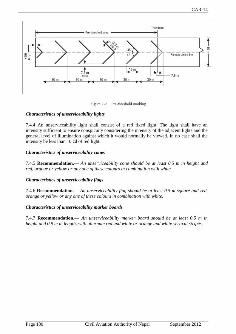
CAR-14
Page 180 Civil Aviation Authority of Nepal September 2012
Characteristics of unserviceability lights
7.4.4 An unserviceability light shall consist of a red fixed light. The light shall have an
intensity sufficient to ensure conspicuity considering the intensity of the adjacent lights and the
general level of illumination against which it would normally be viewed. In no case shall the
intensity be less than 10 cd of red light.
Characteristics of unserviceability cones
7.4.5 Recommendation.— An unserviceability cone should be at least 0.5 m in height and
red, orange or yellow or any one of these colours in combination with white.
Characteristics of unserviceability flags
7.4.6 Recommendation.— An unserviceability flag should be at least 0.5 m square and red,
orange or yellow or any one of these colours in combination with white.
Characteristics of unserviceability marker boards
7.4.7 Recommendation.— An unserviceability marker board should be at least 0.5 m in
height and 0.9 m in length, with alternate red and white or orange and white vertical stripes.

CAR-14
Page 181 Civil Aviation Authority of Nepal September 2012
CHAPTER 8
ELECTRICAL SYSTEMS
8.1 Electrical power supply systems for air navigation facilities
Introductory Note.— The safety of operations at aerodromes depends on the quality of the
supplied power. The total electrical power supply system may include connections to one or
more external sources of electric power supply, one or more local generating facilities and to a
distribution network including transformers and switchgear. Many other aerodrome facilities
supplied from the same system need to be taken into account while planning the electrical
power system at aerodromes.
8.1.1 Adequate primary power supply shall be available at aerodromes for the safe functioning
of air navigation facilities.
8.1.2 The design and provision of electrical power systems for aerodrome visual and radio
navigation aids shall be such that an equipment failure will not leave the pilot with inadequate
visual and non-visual guidance or misleading information.
Note.— The design and installation of the electrical systems need to take into consideration
factors that can lead to malfunction, such as electromagnetic disturbances, line losses, power
quality, etc. Additional guidance is given in the ICAO Aerodrome Design Manual, Part 5.
8.1.3 Recommendation.— Electric power supply connections to those facilities for which
secondary power is required should be so arranged that the facilities are automatically
connected to the secondary power supply on failure of the primary source of power.
8.1.4 Recommendation.— The time interval between failure of the primary source of power
and the complete restoration of the services required by 8.1.10 should be as short as
practicable, except that for visual aids associated with non-precision, precision approach or
take-off runways the requirements of Table 8-1 for maximum switch-over times should apply.
Note.— A definition of switch-over time is given in Chapter 1.
8.1.5 The provision of a definition of switch-over time shall not require the replacement of an
existing secondary power supply before 1 January 2010. However, for a secondary power
supply installed after 4 November 1999, the electric power supply connections to those
facilities for which secondary power is required shall be so arranged that the facilities are
capable of meeting the requirements of Table 8-1 for maximum switch-over times as defined in
Chapter 1.
Visual aids
Application
8.1.6 For a precision approach runway, a secondary power supply capable of meeting the
requirements of Table 8-1 for the appropriate category of precision approach runway shall be
provided. Electric power supply connections to those facilities for which secondary power is
required shall be so arranged that the facilities are automatically connected to the secondary
power supply on failure of the primary source of power.
CAR-14
Page 182 Civil Aviation Authority of Nepal September 2012
8.1.7 For a runway meant for take-off in runway visual range conditions less than a value of
800 m, a secondary power supply capable of meeting the relevant requirements of Table 8-1
shall be provided.
8.1.8 Recommendation.— At an aerodrome where the primary runway is a non-precision
approach runway, a secondary power supply capable of meeting the requirements of Table 8-1
should be provided except that a secondary power supply for visual aids need not be provided
for more than one non-precision approach runway.
8.1.9 Recommendation.— At an aerodrome where the primary runway is a non-instrument
runway, a secondary power supply capable of meeting the requirements of 8.1.4 should be
provided, except that a secondary power supply for visual aids need not be provided when an
emergency lighting system in accordance with the specification of 5.3.2 is provided and
capable of being deployed in 15 minutes.
8.1.10 Recommendation.— The following aerodrome facilities should be provided with a
secondary power supply capable of supplying power when there is a failure of the primary
power supply:
a) the signalling lamp and the minimum lighting necessary to enable air traffic
services personnel to carry out their duties;
Note.— The requirement for minimum lighting may be met by other than electrical
means.
b) all obstacle lights which, in the opinion of the Director General of Civil Aviation
authority of Nepal, are essential to ensure the safe operation of aircraft;
c) approach, runway and taxiway lighting as specified in 8.1.6 to 8.1.9;
c) meteorological equipment;
e) essential security lighting, if provided in accordance with 9.11;
f) essential equipment and facilities for the aerodrome responding emergency
agencies;
g) floodlighting on a designated isolated aircraft parking position if provided in
accordance with 5.3.23.1; and
h) illumination of apron areas over which passengers may walk.
Note.— Specifications for secondary power supply for radio navigation aids and
ground elements of communications systems are given in Annex 10, Part 1, Chapter 2.
8.1.11 Recommendation.— Requirements for a secondary power supply should be met by
either of the following:
- independent public power, which is a source of power supplying the aerodrome
service from a substation other than the normal substation through a transmission line
following a route different from the normal power supply route and such that the
possibility of a simultaneous failure of the normal and independent public power
supplies is extremely remote; or

CAR-14
Page 183 Civil Aviation Authority of Nepal September 2012
- standby power unit(s), which are engine generators, batteries, etc., from which electric
power can be obtained.
Note.— Guidance on electrical systems is included in the Aerodrome Design Manual, Part 5.
8.2 System design
8.2.1 For a runway meant for use in runway visual range conditions less than a value of 550 m,
the electrical systems for the power supply, lighting and control of the lighting systems
included in Table 8-1 shall be so designed that an equipment failure will not leave the pilot
with inadequate visual guidance or misleading information.
Note.— Guidance on means of providing this protection is given in the Aerodrome Design
Manual, Part 5.
8.2.2 Where the secondary power supply of an aerodrome is provided by the use of duplicate
feeders, such supplies shall be physically and electrically separate so as to ensure the required
level of availability and independence.
8.2.3 Where a runway forming part of a standard taxi-route is provided with runway lighting
and taxiway lighting, the lighting systems shall be interlocked to preclude the possibility of
simultaneous operation of both forms of lighting.
8.3 Monitoring
Note.— Guidance on this subject is given in the Aerodrome Design Manual, Part 5.
8.3.1 Recommendation.— A system of monitoring should be employed to indicate the
operational status of the lighting systems.
8.3.2 Where lighting systems are used for aircraft control purposes, such systems shall be
monitored automatically so as to provide an indication of any fault which may affect the
control functions. This information shall be automatically relayed to the air traffic service unit.
8.3.3 Recommendation.— Where a change in the operational status of lights has occurred,
an indication should be provided within two seconds for a stop bar at a runway-holding
position and within five seconds for all other types of visual aids.
8.3.4 Recommendation.— For a runway meant for use in runway visual range conditions less
than a value of 550 m, the lighting systems detailed in Table 8-1 should be monitored
automatically so as to provide an indication when the serviceability level of any element falls
below the minimum serviceability level specified in 10.4.7 to 10.4.11, as appropriate. This
information should be automatically relayed to the maintenance crew.
8.3.5 Recommendation.— For a runway meant for use in runway visual range conditions less
than a value of 550 m, the lighting systems detailed in Table 8-1 should be monitored
automatically to provide an indication when the serviceability level of any element falls below
the minimum level specified by the Director General of Civil Aviation Authority of Nepal below
which operations should not continue. This information should be automatically relayed to the
air traffic services unit and displayed in a prominent position.

CAR-14
Page 184 Civil Aviation Authority of Nepal September 2012
Note.— Guidance on air traffic control interface and visual aids monitoring is included in the
ICAO Aerodrome Design Manual, Part 5.

CAR-14
Page 185 Civil Aviation Authority of Nepal September 2012
CHAPTER- 9
AERODROME OPERATIONAL SERVICES, EQUIPMENT AND INSTALLATIONS
9.1 Aerodrome emergency planning
General
Introductory Note.- Aerodrome emergency planning is the process of preparing an aerodrome
to cope with an emergency occurring at the aerodrome or in its vicinity. The objective of
aerodrome emergency planning is to minimize the effects of an emergency, particularly in
respect of saving lives and maintaining aircraft operations. The aerodrome emergency plan
sets forth the procedures for coordinating the response of different aerodrome agencies (or
services) and of those agencies in the surrounding community that could be of assistance in
responding to the emergency. Guidance material to assist the aerodrome operator in
establishing aerodrome emergency planning is given in the ICAO Airport Services Manual,
Part 7.
9.1.1 An aerodrome emergency plan shall be established at an aerodrome, commensurate with
the aircraft operations and other activities conducted at the aerodrome.
9.1.2 The aerodrome emergency plan shall provide for the coordination of the actions to be
taken in an emergency occurring at an aerodrome or in its vicinity.
Note.1— Examples of emergencies are: aircraft emergencies, sabotage including bomb
threats, unlawfully seized aircraft, dangerous goods occurrences, building fires and natural
disasters.
Note 2.— Examples of public health emergencies are increased risk of travellers or cargo spreading a serious communicable disease internationally through air transport and severe outbreak of a communicable disease potentially affecting a large proportion of aerodrome staff.
9.1.3 The plan shall coordinate the response or participation of all existing agencies which, in
the opinion of the aerodrome operator, could be of assistance in responding to an emergency.
Note 1.- Examples of agencies are:
- on the aerodrome: air traffic control unit, rescue and fire fighting services, aerodrome
administration, medical and ambulance services, aircraft operators, security services,
and police;
- off the aerodrome: fire departments, police, medical and ambulance services, hospitals
and military.
Note 2.— Public health services include planning to minimize adverse effects to the community from
health-related events and deal with population health issues rather than provision of health
services to individuals
9.1.4 Recommendation.— The plan should provide for cooperation and coordination with the
rescue coordination centre, as necessary.
CAR-14
Page 186 Civil Aviation Authority of Nepal September 2012
9.1.5 Recommendation.— The aerodrome emergency plan document should include at least
the following:
a) types of emergencies planned for;
b) agencies involved in the plan;
c) responsibility and role of each agency, the emergency operations centre and the
command post, for each type of emergency;
d) information on names and telephone numbers of offices or people to be contacted
in the case of a particular emergency; and
e) a grid map of the aerodrome and its immediate vicinity.
9.1.6 The plan shall observe Human Factors principles to ensure optimum response by all
existing agencies participating in emergency operations.
Note.— Guidance material on Human Factors principles can be found in the ICAO Human
Factors Training Manual.
Emergency operations centre and command post
9.1.7 Recommendation.— A fixed emergency operations centre and a mobile command post
should be available for use during an emergency.
9.1.8 Recommendation.— The emergency operations centre should be a part of the
aerodrome facilities and should be responsible for the overall coordination and general
direction of the response to an emergency.
9.1.9 Recommendation.— The command post should be a facility capable of being moved
rapidly to the site of an emergency, when required, and should undertake the local
coordination of those agencies responding to the emergency.
9.1.10 Recommendation.— A person should be assigned to assume control of the emergency
operations centre and, when appropriate, another person the command post.
Communication system
9.1.11 Recommendation.— Adequate communication systems linking the command post and
the emergency operations centre with each other and with the participating agencies should be
provided in accordance with the plan and consistent with the particular requirements of the
aerodrome.
Aerodrome emergency exercise
9.1.12 The plan shall contain procedures for periodic testing of the adequacy of the plan and
for reviewing the results in order to improve its effectiveness.
Note.— The plan includes all participating agencies and associated equipment.
9.1.13 The plan shall be tested by conducting:
a) a full-scale aerodrome emergency exercise at intervals not exceeding two years; and
b) partial emergency exercises in the intervening year to ensure that any deficiencies
found during the full-scale aerodrome emergency exercise have been corrected; and

CAR-14
Page 187 Civil Aviation Authority of Nepal September 2012
reviewed thereafter, or after an actual emergency, so as to correct any deficiency found during
such exercises or actual emergency.
Note.— The purpose of a full-scale exercise is to ensure the adequacy of the plan to cope with
different types of emergencies. The purpose of a partial exercise is to ensure the adequacy of
the response to individual participating agencies and components of the plan, such as the
communications system.
Emergencies in difficult environments
9.1.14 The plan shall include the ready availability of and coordination with appropriate
specialist rescue services to be able to respond to emergencies where an aerodrome is located
close to water and/or swampy areas and where a significant portion of approach or departure
operations takes place over these areas.
9.1.15 Recommendation.— At those aerodromes located close to water and/or swampy areas,
or difficult terrain, the aerodrome emergency plan should include the establishment, testing
and assessment at regular intervals of a pre-determined response for the specialist rescue
services.
9.2 Rescue and fire fighting
General
Introductory Note.- The principal objective of a rescue and fire fighting service is to save lives.
For this reason, the provision of means of dealing with an aircraft accident or incident
occurring at, or in the immediate vicinity of, an aerodrome assumes primary importance
because it is within this area that there are the greatest opportunities of saving lives. This must
assume at all times the possibility of, and need for, extinguishing a fire which may occur either
immediately following an aircraft accident or incident, or at any time during rescue
operations.
The most important factors bearing on effective rescue in a survivable aircraft accident are:
the training received, the effectiveness of the equipment and the speed with which personnel
and equipment designated for rescue and fire fighting purposes can be put into use.
Requirements to combat building and fuel farm fires, or to deal with foaming of runways, are
not taken into account.
Application
9.2.1 Rescue and fire fighting equipment and services shall be provided at an aerodrome.
Note.— Public or private organizations, suitably located and equipped, may be designated to
provide the rescue and fire fighting service. It is intended that the fire station housing these
organizations be normally located on the aerodrome, although an off-aerodrome location is
not precluded provided the response time can be met.
9.2.2 Where an aerodrome is located close to water swampy areas, or difficult terrain, and
where a significant portion of approach or departure operations takes place over these areas,
specialist rescue services and fire fighting equipment appropriate to the hazard and risk shall be
available.
CAR-14
Page 188 Civil Aviation Authority of Nepal September 2012
Note 1.— Additional guidance is available in Chapter 13 of the Airport Services Manual, Part
1.
Level of protection to be provided
9.2.3 The level of protection provided at an aerodrome for rescue and fire fighting shall be
appropriate to the aerodrome category determined using the principles in 9.2.5 and 9.2.6,
except that, where the number of movements of the aeroplanes in the highest category
normally using the aerodrome is less than 700 in the busiest consecutive three months, the
level of protection provided shall be not less than one category below the determined category.
Note.— Either a take-off or a landing constitutes a movement.
9.2.4 Recommendation.— The level of protection provided at an aerodrome for rescue and
fire fighting should be equal to the aerodrome category determined using the principles in
9.2.5 and 9.2.6.
9.2.5 The aerodrome category shall be determined from Table 9-1 and shall be based on the
longest aeroplanes normally using the aerodrome and their fuselage width.
Note.— To categorize the aeroplanes using the aerodrome, first evaluate their overall length
and second, their fuselage width.
9.2.6 If, after selecting the category appropriate to the longest aeroplane’s overall length, that
aeroplane’s fuselage width is greater than the maximum width in Table 9-1, column 3 for that
category, then the category for that aeroplane shall actually be one category higher.
Note 1.— See guidance in the Airport Services Manual (Doc 9137), Part l,for categorizing aerodromes, including those for all-cargo aircraft operations, for rescue and fire fighting purposes.
Note 2.— Guidance on training of personnel, rescue equipment for difficult environments and other facilities and services for rescue and fire fighting is given in Attachment A, Section 17, and in the Airport Services Manual (Doc 9137), Part 1.
9.2.7 During anticipated periods of reduced activity, the level of protection available shall be
no less than that needed for the highest category of aeroplane planned to use the aerodrome
during that time irrespective of the number of movements.
Extinguishing agents
9.2.8 Recommendation.— Both principal and complementary agents should normally be
provided at an aerodrome.
Note.— Descriptions of the agents may be found in the ICAO Airport Services Manual, Part 1.
9.2.9 Recommendation.— The principal extinguishing agent should be:
a) a foam meeting the minimum performance level A; or
b) a foam meeting the minimum performance level B; or
c) a combination of these agents;
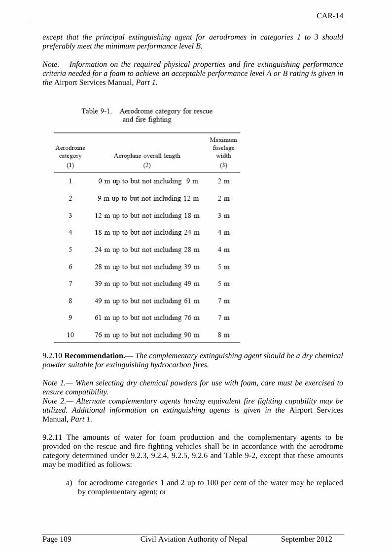
CAR-14
Page 189 Civil Aviation Authority of Nepal September 2012
except that the principal extinguishing agent for aerodromes in categories 1 to 3 should
preferably meet the minimum performance level B.
Note.— Information on the required physical properties and fire extinguishing performance
criteria needed for a foam to achieve an acceptable performance level A or B rating is given in
the Airport Services Manual, Part 1.
9.2.10 Recommendation.— The complementary extinguishing agent should be a dry chemical
powder suitable for extinguishing hydrocarbon fires.
Note 1.— When selecting dry chemical powders for use with foam, care must be exercised to
ensure compatibility.
Note 2.— Alternate complementary agents having equivalent fire fighting capability may be
utilized. Additional information on extinguishing agents is given in the Airport Services
Manual, Part 1.
9.2.11 The amounts of water for foam production and the complementary agents to be
provided on the rescue and fire fighting vehicles shall be in accordance with the aerodrome
category determined under 9.2.3, 9.2.4, 9.2.5, 9.2.6 and Table 9-2, except that these amounts
may be modified as follows:
a) for aerodrome categories 1 and 2 up to 100 per cent of the water may be replaced
by complementary agent; or

CAR-14
Page 190 Civil Aviation Authority of Nepal September 2012
b) for aerodrome categories 3 to 10 when a foam meeting performance level A is used,
up to 30 per cent of the water may be replaced by complementary agent.
For the purpose of agent substitution, the following equivalents shall be used:
1 kg = 1.0 L water for production of a foam
complementary agent meeting performance level A
1 kg = 0.66 L water for production of a foam
complementary agent meeting performance level B
Note 1.— The amounts of water specified for foam production are predicated on an
application rate of 8.2 L/min/m² for a foam meeting performance level A, and 5.5 L/min/m² for
a foam meeting performance level B.
Note 2.— When any other complementary agent is used, the substitution ratios need to be
checked.
9.2.12 Recommendation.— At aerodromes where operations by aeroplanes larger than the average size in a given category are planned, the quantities of water should be recalculated and the amount of water for foam production and the discharge rates for foam solution should be increased accordingly.
Note.— Additional guidance is available in Chapter 2 of the Airport Services Manual (Doc 9137),
Part 1.
9.2.13 The quantity of foam concentrates separately provided on vehicles for foam production
shall be in proportion to the quantity of water provided and the foam concentrate selected.
9.2.14 Recommendation.— The amount of foam concentrate provided on a vehicle should be
sufficient to produce at least two loads of foam solution.
9.2.15 Recommendation.— Supplementary water supplies, for the expeditious replenishment
of rescue and fire fighting vehicles at the scene of an aircraft accident, should be provided.
9.2.16 Recommendation.— When both a foam meeting performance level A and a foam
meeting performance level B are to be used, the total amount of water to be provided for foam
production should first be based on the quantity which would be required if only a foam
meeting performance level A were used, and then reduced by 3 L for each 2 L of water
provided for the foam meeting performance level B.
9.2.17 The discharge rate of the foam solution shall not be less than the rates shown in Table 9-
2.
9.2.18 Recommendation.— The complementary agents should comply with the appropriate
specifications of the International Organization for Standardization (ISO).*
9.2.19 Recommendation.— The discharge rate of complementary agents should be no less
than the values shown in Table 9-2.
_____________________________
* See ISO Publication 7202 (Powder)

CAR-14
Page 191 Civil Aviation Authority of Nepal September 2012
9.2.20 Recommendation.— Dry chemical powders should only be substituted with an agent that has equivalent o better fire fighting capabilities for all types of fires where complementary agent is expected to be used.
9.2.21 Recommendation.— A reserve supply of foam concentrate and complementary agent,
equivalent to 200 per cent of the quantities of these agents to be provided in the rescue and fire
fighting vehicles, should be maintained on the aerodrome for vehicle replenishment purposes.
Where a major delay in the replenishment of this supply is anticipated, the amount of reserve
supply should be increased.
Rescue equipment
9.2.22 Recommendation.— Rescue equipment commensurate with the level of aircraft
operations should be provided on the rescue and fire fighting vehicle(s).
Note.— Guidance on the rescue equipment to be provided at an aerodrome is given in the
Airport Services Manual, Part 1.
Response time
9.2.23 The operational objective of the rescue and fire fighting service shall be to achieve a
response time not exceeding three minutes to any point of each operational runway, in
optimum visibility and surface conditions.
9.2.24 Recommendation.— The operational objective of the rescue and fire fighting service
should be to achieve a response time not exceeding two minutes to any point of each
operational runway, in optimum visibility and surface conditions.

CAR-14
Page 192 Civil Aviation Authority of Nepal September 2012
9.2.25 Recommendation.— The operational objective of the rescue and fire fighting service
should be to achieve a response time not exceeding three minutes to any other part of the
movement area in optimum visibility and surface conditions.
Note 1.— Response time is considered to be the time between the initial call to the rescue and
fire fighting service, and the time when the first responding vehicle(s) is (are) in position to
apply foam at a rate of at least 50 per cent of the discharge rate specified in Table 9-2.
Note 2.— Optimum visibility and surface conditions are defined as daytime, good visibility, no
precipitation with normal response route free of surface contamination e.g. water.ice or snow.
9.2.26 Recommendation.— To meet the operational objective as nearly as possible in less than optimum conditions of visibility, especially during low visibility operations, suitable guidance, equipment and/or procedures for rescue and fire fighting services should be provided.
Note.— Additional guidance is available in the Airport Services Manual (Doc 9137), Part 1.
9.2.27 Any vehicles, other than the first responding vehicle(s), required to deliver the amounts of extinguishing agents specified in Table 9-2 shall ensure continuous agent application and shall arrive no more than four minutes from the initial call.
9.2.28 Recommendation.—Any vehicles, other than the first responding vehicles(s), required to deliver the amounts of extinguishing agents specified in Table 9-2 should ensure continuous agent application and should arrive no more than three minutes from the initial call.
9.2.29 Recommendation.— A system of preventive maintenance of rescue and fire fighting
vehicles should be employed to ensure effectiveness of the equipment and compliance with the
specified response time throughout the life of the vehicle.
Emergency access roads
9.2.30 Recommendation.— Emergency access roads should be provided on an aerodrome
where terrain conditions permit their construction, so as to facilitate achieving minimum
response times. Particular attention should be given to the provision of ready access to
approach areas up to 1 000 m from the threshold, or at least within the aerodrome boundary.
Where a fence is provided, the need for convenient access to outside areas should be taken into
account.
Note.— Aerodrome service roads may serve as emergency access roads when they are suitably
located and constructed.
9.2.31 Recommendation.— Emergency access roads should be capable of supporting the
heaviest vehicles which will use them, and be usable in all weather conditions. Roads within 90
m of a runway should be surfaced to prevent surface erosion and the transfer of debris to the
runway. Sufficient vertical clearance should be provided from overhead obstructions for the
largest vehicles.
9.2.32 Recommendation.— When the surface of the road is indistinguishable from the
surrounding area, edge markers should be placed at intervals of about 10 m.
Fire stations
9.2.33 Recommendation.— All rescue and fire fighting vehicles should normally be housed in
a fire station. Satellite fire stations should be provided whenever the response time cannot be
achieved from a single fire station.

CAR-14
Page 193 Civil Aviation Authority of Nepal September 2012
9.2.34 Recommendation.— The fire station should be located so that the access for rescue
and fire fighting vehicles into the runway area is direct and clear, requiring a minimum
number of turns.
Communication and alerting systems
9.2.35 Recommendation.— A discrete communication system should be provided linking a
fire station with the control tower, any other fire station on the aerodrome and the rescue and
fire fighting vehicles.
9.2.36 Recommendation.— An alerting system for rescue and fire fighting personnel, capable
of being operated from that station, should be provided at a fire station, any other fire station
on the aerodrome and the aerodrome control tower.
Number of rescue and fire fighting vehicles
9.2.37 Recommendation.— The minimum number of rescue and fire fighting vehicles
provided at an aerodrome should be in accordance with the following tabulation:
Note.— Guidance on minimum characteristics of rescue and fire fighting vehicles is given in
the Airport Services Manual, Part 1.
Personnel
9.2.38 All rescue and fire fighting personnel shall be properly trained to perform their duties in
an efficient manner and shall participate in live fire drills commensurate with the types of
aircraft and type of rescue and fire fighting equipment in use at the aerodrome, including
pressure-fed fuel fires.
Note 1.— Guidance to assist the appropriate authority in providing proper training is given in
Attachment A, Section 17; Airport Services Manual, Part 1.
Note 2.— Fires associated with fuel discharged under very high pressure from a ruptured fuel
tank are known as “pressure-fed fuel fires”.
9.2.39 The rescue and fire fighting personnel training programme shall include training in
human performance, including team coordination.

CAR-14
Page 194 Civil Aviation Authority of Nepal September 2012
Note.— Guidance material to design training programmes on human performance and team
coordination can be found in the Human Factors Training Manual.
9.2.40 Recommendation.— During flight operations, sufficient trained personnel should be
detailed and be readily available to ride the rescue and fire fighting vehicles and to operate the
equipment at maximum capacity. These trained personnel should be deployed in a way that
ensures that minimum response times can be achieved and that continuous agent application at
the appropriate rate can be fully maintained. Consideration should also be given for personnel
to use hand lines, ladders and other rescue and fire fighting equipment normally associated
with aircraft rescue and fire fighting operations.
9.2.41 Recommendation.— In determining the number of personnel required to provide for
rescue, consideration should be given to the types of aircraft using the aerodrome.
9.2.42 All responding rescue and fire fighting personnel shall be provided with protective
clothing and respiratory equipment to enable them to perform their duties in an effective
manner.
9.3 Disabled aircraft removal
Note.— Guidance on removal of a disabled aircraft, including recovery equipment, is given in
the Airport Services Manual, Part 5. See also Annex 13 concerning protection of evidence,
custody and removal of aircraft.
9.3.1 Recommendation.— A plan for the removal of an aircraft disabled on, or adjacent to,
the movement area should be established for an aerodrome, and a coordinator designated to
implement the plan, when necessary.
9.3.2 Recommendation.— The disabled aircraft removal plan should be based on the
characteristics of the aircraft that may normally be expected to operate at the aerodrome, and
include among other things:
a) a list of equipment and personnel on, or in the vicinity of, the aerodrome which
would be available for such purpose; and
b) arrangements for the rapid receipt of aircraft recovery equipment kits available from
other aerodromes.
9.4 Wildlife strike hazard reduction
Note.—The presence of wildlife (birds and animals) on and in the aerodrome vicinity poses a serious threat to aircraft operational safety.
9.4.1 The wildlife strike hazard on, or in the vicinity of, an aerodrome shall be assessed
through:
a) the establishment of a national procedure for recording and reporting bird strikes to
aircraft;
b) the collection of information from aircraft operators, airport personnel and other
sources on the presence of wildlife on or around the aerodrome constituting a
potential hazard to aircraft operations; and

CAR-14
Page 195 Civil Aviation Authority of Nepal September 2012
c) an ongoing evaluation of the wildlife hazard by competent personnel.
Note:- See Annex 15, Chapter 8.
9.4.2 Aerodrome operator shall maintain a data base of wildlife strikes and the wildlife strike
reports shall be provided to the Director General of Civil Aviation Authority of Nepal on
monthly basis. The Director General of Civil Aviation Authority of Nepal will compile and
forward the reports to the ICAO for inclusion in the ICAO Bird Strike Information System
(IBIS) database.
Note.— The IBIS is designed to collect and disseminate information on wildlife strikes to
aircraft. Information on the system is included in the ICAO Manual on the ICAO Bird Strike
Information System (IBIS).
9.4.3 Action shall be taken to decrease the risk to aircraft operations by adopting measures to
minimize the likelihood of collisions between wildlife and aircraft.
Note.— Guidance on effective measures for establishing whether or not wildlife, on or near an
aerodrome, constitute a potential hazard to aircraft operations, and on methods for
discouraging their presence, is given in the Airport Services Manual, Part 3.
9.4.4 The aerodrome operator shall take action to eliminate or to prevent the establishment of
garbage disposal dumps or any such other source which may attract wildlife to the aerodrome,
or in the vicinity, unless an appropriate wildlife assessment indicates that they are unlikely to
create conditions conducive to a wildlife hazard problem. Where the elimination of existing
sites is not possible, the aerodrome operator shall ensure that any risk to aircraft posed by these
sites is assessed and reduced to as low as reasonably practicable.
9.4.4 Recommendation.— States should give due consideration to aviation safety concerns related to land developments in the vicinity of the aerodrome that may attract wildlife.
9.5 Apron management service
9.5.1 Recommendation.— When warranted by the volume of traffic and operating conditions,
an appropriate apron management service should be provided on an apron by an aerodrome
ATS unit, by another aerodrome operating authority, or by a cooperative combination of these,
in order to:
a) regulate movement with the objective of preventing collisions between aircraft, and
between aircraft and obstacles;
b) regulate entry of aircraft into, and coordinate exit of aircraft from, the apron with
the aerodrome control tower; and
c) ensure safe and expeditious movement of vehicles and appropriate regulation of
other activities.
9.5.2 Recommendation.— When the aerodrome control tower does not participate in the
apron management service, procedures should be established to facilitate the orderly
transition of aircraft between the apron management unit and the aerodrome control tower.

CAR-14
Page 196 Civil Aviation Authority of Nepal September 2012
Note.— Guidance on an apron management service is given in the ICAO Airport Services
Manual, Part 8 and in the Manual of Surface Movement Guidance and Control Systems
(SMGCS).
9.5.3 An apron management service shall be provided with radiotelephony communications
facilities.
9.5.4 Where low visibility procedures are in effect, persons and vehicles operating on an apron
shall be restricted to the essential minimum.
Note.— Guidance on related special procedures is given in the Manual of Surface Movement
Guidance and Control Systems (SMGCS).
9.5.5 An emergency vehicle responding to an emergency shall be given priority over all other
surface movement traffic.
9.5.6 A vehicle operating on an apron shall:
a) give way to an emergency vehicle; an aircraft taxiing, about to taxi, or being pushed
or towed; and
b) give way to other vehicles in accordance with local regulations.
9.5.7 An aircraft stand shall be visually monitored to ensure that the recommended clearance
distances are provided to an aircraft using the stand.
9.6 Ground servicing of aircraft
9.6.1 Fire extinguishing equipment suitable for at least initial intervention in the event of a fuel
fire and personnel trained in its use shall be readily available during the ground servicing of an
aircraft, and there shall be a means of quickly summoning the rescue and fire fighting service
in the event of a fire or major fuel spill.
9.6.2 When aircraft refuelling operations take place while passengers are embarking, on board
or disembarking, ground equipment shall be positioned so as to allow:
a) the use of a sufficient number of exits for expeditious evacuation; and
b) a ready escape route from each of the exits to be used in an emergency.
9.7 Aerodrome vehicle operations
Note 1.— Guidance on aerodrome vehicle operations is contained in Attachment A, Section 18
and on traffic rules and regulations for vehicles in the Manual of Surface Movement Guidance
and Control Systems (SMGCS).
Note 2.— It is intended that roads located on the movement area be restricted to the exclusive
use of aerodrome personnel and other authorized persons, and that access to the public
buildings by an unauthorized person will not require use of such roads.
9.7.1 A vehicle shall be operated:
a) on a manoeuvring area only as authorized by the aerodrome control tower; and
CAR-14
Page 197 Civil Aviation Authority of Nepal September 2012
b) on an apron only as authorized by the airport operator.
9.7.2 The driver of a vehicle on the movement area shall comply with all mandatory
instructions conveyed by markings and signs unless otherwise authorized by:
a) the aerodrome control tower when on the manoeuvring area; or
b) the airport operator when on the apron.
9.7.3 The driver of a vehicle on the movement area shall comply with all mandatory
instructions conveyed by lights.
9.7.4 The driver of a vehicle on the movement area shall be appropriately trained for the tasks
to be performed and shall comply with the instructions issued by:
a) the aerodrome control tower, when on the manoeuvring area; and
b) the airport operator, when on the apron.
9.7.5 The driver of a radio-equipped vehicle shall establish satisfactory two-way radio
communication with the aerodrome control tower before entering the manoeuvring area and
with the aerodrome operator before entering the apron. The driver shall maintain a continuous
listening watch on the assigned frequency when on the movement area.
9.8 Surface movement guidance and control systems
Application
9.8.1 A surface movement guidance and control system shall be provided at an aerodrome.
Note.— Guidance on surface movement guidance and control systems is contained in the
Manual of Surface Movement Guidance and Control Systems (SMGCS).
Characteristics
9.8.2 Recommendation.— The design of a surface movement guidance and control system
should take into account:
a) the density of air traffic;
b) the visibility conditions under which operations are intended;
c) the need for pilot orientation;
d) the complexity of the aerodrome layout; and
e) movements of vehicles.
9.8.3 Recommendation.— The visual aid components of a surface movement guidance and
control system, i.e. markings, lights and signs should be designed to conform with the relevant
specifications in 5.2, 5.3 and 5.4, respectively.
9.8.4 Recommendation.— A surface movement guidance and control system should be
designed to assist in the prevention of inadvertent incursions of aircraft and vehicles onto an
active runway.

CAR-14
Page 198 Civil Aviation Authority of Nepal September 2012
9.8.5 Recommendation.— The system should be designed to assist in the prevention of
collisions between aircraft, and between aircraft and vehicles or objects, on any part of the
movement area.
Note.— Guidance on control of stop bars through induction loops and on a visual taxiing
guidance and control system is contained in the Aerodrome Design Manual, Part 4.
9.8.6 Where a surface movement guidance and control system is provided by selective
switching of stop bars and taxiway centre line lights, the following requirements shall be met:
a) taxiway routes which are indicated by illuminated taxiway centre line lights shall be
capable of being terminated by an illuminated stop bar;
b) the control circuits shall be so arranged that when a stop bar located ahead of an
aircraft is illuminated, the appropriate section of taxiway centre line lights beyond it
is suppressed; and
c) the taxiway centre line lights are activated ahead of an aircraft when the stop bar is
suppressed.
Note 1.— See Sections 5.3.16 and 5.3.19 for specifications on taxiway centre line lights and
stop bars, respectively.
Note 2.— Guidance on installation of stop bars and taxiway centre line lights in surface
movement guidance and control systems is given in the Aerodrome Design Manual, Part 4.
9.8.7 Recommendation.— Surface movement radar for the manoeuvring area should be
provided at an aerodrome intended for use in runway visual range conditions less than a value
of 350 m.
9.8.8 Recommendation.— Surface movement radar for the manoeuvring area should be
provided at an aerodrome other than that in 9.8.7 when traffic density and operating
conditions are such that regularity of traffic flow cannot be maintained by alternative
procedures and facilities.
Note.— Guidance on the use of surface movement radar is given in the Manual of Surface
Movement Guidance and Control Systems (SMGCS) and in the Air Traffic Services Planning
Manual.
9.9 Siting of equipment and installations on operational areas
Note 1.— Requirements for obstacle limitation surfaces are specified in 4.2.
Note 2.— The design of light fixtures and their supporting structures, light units of visual
approach slope indicators, signs, and markers, is specified in 5.3.1, 5.3.5, 5.4.1 and 5.5.1,
respectively. Guidance on the frangible design of visual and non-visual aids for navigation is
given in the Aerodrome Design Manual, Part 6.
9.9.1 Unless its function requires it to be there for air navigation purposes, no equipment or
installation shall be:
a) on a runway strip, a runway end safety area, a taxiway strip or within the distances
specified in Table 3-1, column 11, if it would endanger an aircraft; or

CAR-14
Page 199 Civil Aviation Authority of Nepal September 2012
b) on a clearway if it would endanger an aircraft in the air.
9.9.2 Any equipment or installation required for air navigation purposes which must be
located:
a) on that portion of a runway strip within:
1) 75 m of the runway centre line where the code number is 3 or 4; or
2) 45 m of the runway centre line where the code number is 1 or 2; or
b) on a runway end safety area, a taxiway strip or within the distances specified in
Table 3-1; or
c) on a clearway and which would endanger an aircraft in the air;
shall be frangible and mounted as low as possible.
9.9.3 Recommendation.— Any equipment or installation required for air navigation purposes
which must be located on the non-graded portion of a runway strip should be regarded as an
obstacle and should be frangible and mounted as low as possible.
Note.— Guidance on the siting of navigation aids is contained in the Aerodrome Design
Manual, Part 6.
9.9.4 Unless its function requires it to be there for air navigation purposes, no equipment or
installation shall be located within 240 m from the end of the strip and within:
a) 60 m of the extended centre line where the code number is 3 or 4; or
b) 45 m of the extended centre line where the code number is 1 or 2;
of a precision approach runway category I, II or III.
9.9.5 Any equipment or installation required for air navigation purposes which must be located
on or near a strip of a precision approach runway category I, II or III and which:
a) is situated on that portion of the strip within 77.5 m of the runway centre line where
the code number is 4 and the code letter is F; or
b) is situated within 240 m from the end of the strip and within:
1) 60 m of the extended runway centre line where the code number is 3 or 4; or
2) 45 m of the extended runway centre line where the code number is 1 or 2; or
c) penetrates the inner approach surface, the inner transitional surface or the balked
landing surface;
shall be frangible and mounted as low as possible.
Note.— See 5.3.1.5 for the protection date for existing elevated approach lights.
CAR-14
Page 200 Civil Aviation Authority of Nepal September 2012
9.9.6 Recommendation.— Any equipment or installation required for air navigation purposes
which is an obstacle of operational significance in accordance with 4.2.4, 4.2.11, 4.2.20 or
4.2.27 should be frangible and mounted as low as possible.
9.10 Fencing
Application
9.10.1 A fence or other suitable barrier shall be provided on an aerodrome to prevent the
entrance to the movement area of animals large enough to be a hazard to aircraft.
9.10.2 A fence or other suitable barrier shall be provided on an aerodrome to deter the
inadvertent or premeditated access of an unauthorized person onto a non-public area of the
aerodrome.
Note 1.— This is intended to include the barring of sewers, ducts, tunnels, etc., where
necessary to prevent access.
Note 2.— Special measures may be required to prevent the access of an unauthorized person to
runways or taxiways which overpass public roads.
9.10.3 Suitable means of protection shall be provided to deter the inadvertent or premeditated
access of unauthorized persons into ground installations and facilities essential for the safety of
civil aviation located off the aerodrome.
Location
9.10.4 The fence or barrier shall be located so as to separate the movement area and other
facilities or zones on the aerodrome vital to the safe operation of aircraft from areas open to
public access.
9.10.5 Recommendation.— When greater security is thought necessary, a cleared area
should be provided on both sides of the fence or barrier to facilitate the work of patrols and to
make trespassing more difficult. Consideration should be given to the provision of a perimeter
road inside the aerodrome fencing for the use of both maintenance personnel and security
patrols.
9.11 Security lighting
Recommendation.— At an aerodrome where it is deemed desirable for security reasons, a
fence or other barrier provided for the protection of international civil aviation and its
facilities should be illuminated at a minimum essential level. Consideration should be given to
locating lights so that the ground area on both sides of the fence or barrier, particularly at
access points, is illuminated.

CAR-14
Page 201 Civil Aviation Authority of Nepal September 2012
CHAPTER- 10
AERODROME MAINTENANCE
10.1 General
10.1.1 Recommendation.— A maintenance programme, including preventive maintenance
where appropriate, should be established at an aerodrome to maintain facilities in a condition
which does not impair the safety, regularity or efficiency of air navigation.
Note 1.— Preventive maintenance is programmed maintenance work done in order to prevent
a failure or degradation of facilities.
Note 2.— “Facilities” are intended to include such items as pavements, visual aids, fencing,
drainage systems and buildings.
10.1.2 Recommendation.— The design and application of the maintenance programme
should observe Human Factors principles.
Note.— Guidance material on Human Factors principles can be found in the Human Factors
Training Manual.
10.2 Pavements
10.2.1 The surface of pavements (runways, taxiways, aprons and adjacent areas) shall be kept
clear of any loose stones or other objects that might cause damage to aircraft structures or
engines, or impair the operation of aircraft systems.
Note 1.— See 2.9.3 for inspections of movement areas.
Note 2.— Guidance on carrying out daily inspections of the movement area is given in the Airport Services Manual, Part 8, the Manual of Surface Movement Guidance and Control Systems (SMGCS) and the Advanced Surface Movement Guidance and Control Systems (A-SMGCS) Manual .
Note 3.— Additional guidance on sweeping/cleaning of surfaces is contained in the Airport Services Manual, Part 9.
Note 4.— Guidance on precautions to be taken in regard to the surface of shoulders is given in Attachment A, Section 8, and the Aerodrome Design Manual, Part 2.
10.2.2 The surface of a runway shall be maintained in a condition such as to prevent formation
of harmful irregularities.
Note.— See Attachment A, Section 5.
10.2.3 Measurements of the friction characteristics of a runway surface shall be made
periodically with a continuous friction measuring device using self-wetting features.
Note.— Guidance on evaluating the friction characteristics of a runway is provided in
Attachment A, Section 7. Additional guidance is included in the Airport Services Manual, Part
2.

CAR-14
Page 202 Civil Aviation Authority of Nepal September 2012
10.2.4 Corrective maintenance action shall be taken when the friction characteristics for either
the entire runway or a portion thereof are below a minimum friction level specified in the
Table A - 1, Attachment A.
Note.— A portion of runway in the order of 100 m long may be considered significant for
maintenance or reporting action.
10.2.5 Recommendation.— Corrective maintenance action should be considered when the
friction characteristics for either the entire runway or a portion thereof are below a
maintenance planning level specified in the Table A - 1, Attachment A.
10.2.6 Recommendation.— When there is reason to believe that the drainage characteristics
of a runway, or portions thereof, are poor due to slopes or depressions, then the runway
friction characteristics should be assessed under natural or simulated conditions that are
representative of local rain and corrective maintenance action should be taken as necessary.
10.2.7 Recommendation.— When a taxiway is used by turbine-engined aeroplanes, the
surface of the taxiway shoulders should be maintained so as to be free of any loose stones or
other objects that could be ingested by the aeroplane engines.
Note.— Guidance on this subject is given in the Aerodrome Design Manual, Part 2.
10.2.8 The surface of a paved runway shall be maintained in a condition so as to provide good
friction characteristics and low rolling resistance. Snow, slush, ice, standing water, mud, dust,
sand, oil, rubber deposits and other contaminants shall be removed as rapidly and completely
as possible to minimize accumulation.
Note.— Guidance on determining and expressing the friction characteristics when conditions
of snow or ice cannot be avoided is given in Attachment A, Section 6. The Airport Services
Manual, Part 2, contains further information on this subject, on improving friction
characteristics and on clearing of runways.
10.2.9 Recommendation.— A taxiway should be kept clear of snow, slush, ice, etc., to the
extent necessary to enable aircraft to be taxied to and from an operational runway.
10.2.10 Recommendation.— Aprons should be kept clear of snow, slush, ice, etc., to the
extent necessary to enable aircraft to manoeuvre safely or, where appropriate, to be towed or
pushed.
10.2.11 Recommendation.— Whenever the clearance of snow, slush, ice, etc., from the
various parts of the movement area cannot be carried out simultaneously, the order of priority
should be as follows but may be altered following, as necessary, consultation with the
aerodrome users:
1st — runway(s) in use;
2nd — taxiways serving runway(s) in use;
3rd — apron(s);
4th — holding bays; and
5th — other areas.
10.2.12 Recommendation.— Chemicals to remove or to prevent the formation of ice and frost
on aerodrome pavements should be used when conditions indicate their use could be effective.
Caution should be exercised in the application of the chemicals so as not to create a more
CAR-14
Page 203 Civil Aviation Authority of Nepal September 2012
slippery condition.
Note.— Guidance on the use of chemicals for aerodrome pavements is given in the Airport
Services Manual, Part 2.
10.2.13 Chemicals which may have harmful effects on aircraft or pavements, or chemicals
which may have toxic effects on the aerodrome environment, shall not be used.
10.3 Runway pavement overlays
Note.— The following specifications are intended for runway pavement overlay projects when
the runway is to be returned to an operational status before overlay of the entire runway is
complete thus normally necessitating a temporary ramp between the new and old runway
surfaces. Guidance on overlaying pavements and assessing their operational status is given in
the Aerodrome Design Manual, Part 3.
10.3.1 The longitudinal slope of the temporary ramp, measured with reference to the existing
runway surface or previous overlay course, shall be:
a) 0.5 to 1.0 per cent for overlays up to and including 5 cm in thickness; and
b) not more than 0.5 per cent for overlays more than 5 cm in thickness.
10.3.2 Recommendation.— Overlaying should proceed from one end of the runway toward
the other end so that based on runway utilization most aircraft operations will experience a
down ramp.
10.3.3 Recommendation.— The entire width of the runway should be overlaid during each
work session.
10.3.4 Before a runway being overlaid is returned to a temporary operational status, a runway
centre line marking conforming to the specifications in Section 5.2.3 shall be provided.
Additionally, the location of any temporary threshold shall be identified by a 3.6 m wide
transverse stripe.
10.4 Visual aids
Note.— These specifications are intended to define the maintenance performance level
objectives. They are not intended to define whether the lighting system is operationally out of
service.
10.4.1 A light shall be deemed to be unserviceable when the main beam average intensity is
less than 50 per cent of the value specified in the appropriate figure in Appendix 2. For light
units where the designed main beam average intensity is above the value shown in Appendix 2,
the 50 per cent value shall be related to that design value.
10.4.2 A system of preventive maintenance of visual aids shall be employed to ensure lighting
and marking system reliability.
Note.— Guidance on preventive maintenance of visual aids is given in the Airport Services
Manual, Part 9.
CAR-14
Page 204 Civil Aviation Authority of Nepal September 2012
10.4.3 Recommendation.— The system of preventive maintenance employed for a precision
approach runway category II or III should include at least the following checks:
a) visual inspection and in-field measurement of the intensity, beam spread and
orientation of lights included in the approach and runway lighting systems;
b) control and measurement of the electrical characteristics of each circuitry included
in the approach and runway lighting systems; an
c) control of the correct functioning of light intensity settings used by air traffic
control.
10.4.4 Recommendation.— In-field measurement of intensity, beam spread and orientation of
lights included in approach and runway lighting systems for a precision approach runway
category II or III should be undertaken by measuring all lights, as far as practicable, to ensure
conformance with the applicable specification of Appendix 2.
10.4.5 Recommendation.— Measurement of intensity, beam spread and orientation of lights
included in approach and runway lighting systems for a precision approach runway category
II or III should be undertaken using a mobile measuring unit of sufficient accuracy to analyze
the characteristics of the individual lights.
10.4.6 Recommendation.— The frequency of measurement of lights for a precision approach
runway category II or III should be based on traffic density, the local pollution level, the
reliability of the installed lighting equipment and the continuous assessment of the results of
the in-field measurements but in any event should not be less than twice a year for in-pavement
lights and not less than once a year for other lights.
10.4.7 The system of preventive maintenance employed for a precision approach runway
category II or III shall have as its objective that, during any period of category II or III
operations, all approach and runway lights are serviceable, and that in any event at least:
a) 95 per cent of the lights are serviceable in each of the following particular
significant elements:
1) precision approach category II and III lighting system, the inner 450 m;
2) runway centre line lights;
3) runway threshold lights; and
4) runway edge lights;
b) 90 per cent of the lights are serviceable in the touchdown zone lights;
c) 85 per cent of the lights are serviceable in the approach lighting system beyond 450
m; and
d) 75 per cent of the lights are serviceable in the runway end lights.
In order to provide continuity of guidance, the allowable percentage of unserviceable lights
shall not be permitted in such a way as to alter the basic pattern of the lighting system.
Additionally, an unserviceable light shall not be permitted adjacent to another unserviceable

CAR-14
Page 205 Civil Aviation Authority of Nepal September 2012
light, except in a barrette or a crossbar where two adjacent unserviceable lights may be
permitted.
Note.— With respect to barrettes, crossbars and runway edge lights, lights are considered to
be adjacent if located consecutively and:
- laterally: in the same barrette or crossbar; or
- longitudinally: in the same row of edge lights or barrettes.
10.4.8 The system of preventive maintenance employed for a stop bar provided at a runway-
holding position used in conjunction with a runway intended for operations in runway visual
range conditions less than a value of 350 m shall have the following objectives:
a) no more than two lights will remain unserviceable; and
b) two adjacent lights will not remain unserviceable unless the light spacing is
significantly less than that specified.
10.4.9 The system of preventive maintenance employed for a taxiway intended for use in
runway visual range conditions less than a value of 350 m shall have as its objective that no
two adjacent taxiway centre line lights be unserviceable.
10.4.10 The system of preventive maintenance employed for a precision approach runway
category I shall have as its objective that, during any period of category I operations, all
approach and runway lights are serviceable, and that in any event at least 85 per cent of the
lights are serviceable in each of the following:
a) precision approach category I lighting system;
b) runway threshold lights;
c) runway edge lights; and
d) runway end lights.
In order to provide continuity of guidance an unserviceable light shall not be permitted
adjacent to another unserviceable light unless the light spacing is significantly less than that
specified.
Note.— In barrettes and crossbars, guidance is not lost by having two adjacent unserviceable
lights.
10.4.11 The system of preventive maintenance employed for a runway meant for take-off in
runway visual range conditions less than a value of 550 m shall have as its objective that,
during any period of operations, all runway lights are serviceable and that in any event:
a) at least 95 per cent of the lights are serviceable in the runway centre line lights
(where provided) and in the runway edge lights; and
b) at least 75 per cent of the lights are serviceable in the runway end lights.
In order to provide continuity of guidance, an unserviceable light shall not be permitted
adjacent to another unserviceable light.

CAR-14
Page 206 Civil Aviation Authority of Nepal September 2012
10.4.12 The system of preventive maintenance employed for a runway meant for take-off in
runway visual range conditions of a value of 550 m or greater shall have as its objective that,
during any period of operations, all runway lights are serviceable and that, in any event, at least
85 per cent of the lights are serviceable in the runway edge lights and runway end lights. In
order to provide continuity of guidance, an unserviceable light shall not be permitted adjacent
to another unserviceable light.
10.4.13 Recommendation.— During low visibility procedures the aerodrome operator should
restrict construction or maintenance activities in the proximity of aerodrome electrical
systems.

CAR-14
Page 207 Civil Aviation Authority of Nepal September 2012
APPENDIX- 1
COLOURS FOR AERONAUTICAL GROUND LIGHTS, MARKINGS, SIGNS AND
PANELS
1. General
Introductory Note.- The following specifications define the chromaticity limits of colours to be
used for aeronautical ground lights, markings, signs and panels. The specifications are in
accord with the 1983 specifications of the International Commission on Illumination (CIE).
It is not possible to establish specifications for colours such that there is no possibility of
confusion. For reasonably certain recognition, it is important that the eye illumination be well
above the threshold of perception, that the colour not be greatly modified by selective
atmospheric attenuations and that the observer’s colour vision be adequate. There is also a
risk of confusion of colour at an extremely high level of eye illumination such as may be
obtained from a high-intensity source at very close range. Experience indicates that
satisfactory recognition can be achieved if due attention is given to these factors.
The chromaticities are expressed in terms of the standard observer and coordinate system
adopted by the International Commission on Illumination (CIE) at its Eighth Session at
Cambridge, England, in 1931.*
2. Colours for aeronautical ground lights
2.1 Chromaticities
2.1.1 The chromaticities of aeronautical ground lights shall be within the following boundaries:
CIE Equations (see Figure A1-1):
a) Red
Purple boundary y = 0.980 – x
Yellow boundary y = 0.335
b) Yellow
Red boundary y = 0.382
White boundary y = 0.790 – 0.667x
Green boundary y = x – 0.120
c) Green
Yellow boundary x = 0.360 – 0.080y
White boundary x = 0.650y
Blue boundary y = 0.390 – 0.171x
d) Blue
Green boundary y = 0.805x + 0.065
White boundary y = 0.400 – x
Purple boundary x = 0.600y + 0.133
_______________________
* See CIE Publication No 15, Colorimetry (1971)

CAR-14
Page 208 Civil Aviation Authority of Nepal September 2012
e) White
Yellow boundary x = 0.500
Blue boundary x = 0.285
Green boundary y = 0.440
and y = 0.150 + 0.640x
Purple boundary y = 0.050 + 0.750x
and y = 0.382
f) Variable white
Yellow boundary x = 0.255 + 0.750y
and x = 1.185 – 1.500 y
Blue boundary x = 0.285
Green boundary y = 0.440
and y = 0.150 + 0.640x
Purple boundary y = 0.050 + 0.750x
and y = 0.382
Note.— Guidance on chromaticity changes resulting from the effect of temperature on filtering
elements is given in the Aerodrome Design Manual, Part 4.
2.1.2 Recommendation.— Where dimming is not required, or where observers with defective
colour vision must be able to determine the colour of the light, green signals should be within
the following boundaries:
Yellow boundary y = 0.726 – 0.726x
White boundary x = 0.650y
Blue boundary y = 0.390 – 0.171x
2.1.3 Recommendation.— Where increased certainty of recognition is more important than
maximum visual range, green signals should be within the following boundaries:
Yellow boundary y = 0.726 – 0.726x
White boundary x = 0.625y – 0.041
Blue boundary y = 0.390 – 0.171x
2.2 Discrimination between lights
2.2.1 Recommendation.— If there is a requirement to discriminate yellow and white from
each other, they should be displayed in close proximity of time or space as, for example, by
being flashed successively from the same beacon.
2.2.2 Recommendation.— If there is a requirement to discriminate yellow from green and/or
white, as for example on exit taxiway centre line lights, the y coordinates of the yellow light
should not exceed a value of 0.40.
Note.— The limits of white have been based on the assumption that they will be used in
situations in which the characteristics (colour temperature) of the light source will be
substantially constant.

CAR-14
Page 209 Civil Aviation Authority of Nepal September 2012
2.2.3 Recommendation.— The colour variable white is intended to be used only for lights that
are to be varied in intensity, e.g. to avoid dazzling. If this colour is to be discriminated from
yellow, the lights should be so designed and operated that:
a) the x coordinate of the yellow is at least 0.050 greater than the x coordinate of the
white; and
b) the disposition of the lights will be such that the yellow lights are displayed
simultaneously and in close proximity to the white lights.
2.2.4 The colour of aeronautical ground lights shall be verified as being within the boundaries
specified in Figure A1-1 by measurement at five points within the area limited by the
innermost isocandela curve (isocandela diagrams in Appendix 2 refer), with operation at rated
current or voltage. In the case of elliptical or circular isocandela curves, the colour
measurements shall be taken at the centre and at the horizontal and vertical limits. In the case
of rectangular isocandela curves, the colour measurements shall be taken at the centre and the
limits of the diagonals (corners). In addition, the colour of the light shall be checked at the
outermost isocandela curve to ensure that there is no colour shift that might cause signal
confusion to the pilot.
Note 1.— For the outermost isocandela curve, a measurement of colour coordinates should be
made and recorded for review and judgement of acceptability by the appropriate authority.
Note 2.— Certain light units may have application so that they may be viewed and used by
pilots from directions beyond that of the outermost isocandela curve (e.g. stop bar lights at
significantly wide runway-holding positions). In such instances, the appropriate authority
should assess the actual application and if necessary require a check of colour shift at angular
ranges beyond the outermost curve.
2.2.5 In the case of visual approach slope indicators and other light units having a colour
transition sector, the colour shall be measured at points in accordance with 2.2.4, except that
the colour areas shall be treated separately and no point shall be within 0.5 degrees of the
transition sector.
3. Colours for markings, signs and panels
Note 1.— The specifications of surface colours given below apply only to freshly coloured
surfaces. Colours used for markings, signs and panels usually change with time and therefore
require renewal.
Note 2.— Guidance on surface colours is contained in the CIE document entitled
Recommendations for Surface Colours for Visual Signalling — Publication No. 39-2 (TC-106)
1983.
Note 3.— The specifications recommended in 3.4 for transilluminated panels are interim in
nature and are based on the CIE specifications for transilluminated signs. It is intended that
these specifications will be reviewed and updated as and when CIE develops specifications for
transilluminated panels.
3.1 The chromaticities and luminance factors of ordinary colours, colours of retro-reflective
materials and colours of transilluminated (internally illuminated) signs and panels shall be
determined under the following standard conditions:

CAR-14
Page 210 Civil Aviation Authority of Nepal September 2012
a) angle of illumination: 45°;
b) direction of view: perpendicular to surface; and
c) illuminant: CIE standard illuminant D65.
3.2 Recommendation.— The chromaticity and luminance factors of ordinary colours for
markings and externally illuminated signs and panels should be within the following
boundaries when determined under standard conditions.
CIE Equations (see Figure A1-2):
a) Red
Purple boundary y = 0.345 – 0.051x
White boundary y = 0.910 – x
Orange boundary y = 0.314 + 0.047x
Luminance factor ß = 0.07 (mnm)
b) Orange
Red boundary y = 0.285 + 0.100x
White boundary y = 0.940 – x
Yellow boundary y = 0.250 + 0.220x
Luminance factor ß = 0.20 (mnm)
c) Yellow
Orange boundary y = 0.108 + 0.707x
White boundary y = 0.910 – x
Green boundary y = 1.35x – 0.093
Luminance factor ß = 0.45 (mnm)
d) White
Purple boundary y = 0.010 + x
Blue boundary y = 0.610 – x
Green boundary y = 0.030 + x
Yellow boundary y = 0.710 – x
Luminance factor ß = 0.75 (mnm)
e) Black
Purple boundary y = x – 0.030
Blue boundary y = 0.570 – x
Green boundary y = 0.050 + x
Yellow boundary y = 0.740 – x
Luminance factor ß = 0.03 (max)
f) Yellowish green
Green boundary y = 1.317x + 0.4
White boundary y = 0.910 – x
Yellow boundary y = 0.867x + 0.4
g) Green Yellow boundary x = 0.313
White boundary y = 0.243 + 0.670x

CAR-14
Page 211 Civil Aviation Authority of Nepal September 2012
Blue boundary y = 0.493 - 0.524x Luminance factor β = 0.10 (mnm) Note.— The small separation between surface red and surface orange is not sufficient to
ensure the distinction of these colours when seen separately.
3.3 Recommendation.— The chromaticity and luminance factors of colours of retro-reflective
materials for markings, signs and panels should be within the following boundaries when
determined under standard conditions.
CIE Equations (see Figure A1-3):
a) Red
Purple boundary y = 0.345 – 0.051x
White boundary y = 0.910 – x
Orange boundary y = 0.314 + 0.047x
Luminance factor ß = 0.03 (mnm)
b) Orange
Red boundary y = 0.265 + 0.205x
White boundary y = 0.910 – x
Yellow boundary y = 0.207 + 0.390x
Luminance factor ß = 0.14 (mnm)
c) Yellow
Orange boundary y = 0.160 + 0.540x
White boundary y = 0.910 – x
Green boundary y = 1.35x – 0.093
Luminance factor ß = 0.16 (mnm)
d) White
Purple boundary y = x
Blue boundary y = 0.610 – x
Green boundary y = 0.040 + x
Yellow boundary y = 0.710 – x
Luminance factor ß = 0.27 (mnm)
e) Blue
Green boundary y = 0.118 + 0.675x
White boundary y = 0.370 – x
Purple boundary y = 1.65x – 0.187
Luminance factor ß = 0.01 (mnm)
f) Green
Yellow boundary y = 0.711 – 1.22x
White boundary y = 0.243 + 0.670x
Blue boundary y = 0.405 – 0.243x
Luminance factor ß = 0.03 (mnm)
3.4 Recommendation.— The chromaticity and luminance factors of colours for
transilluminated (internally illuminated) signs and panels should be within the following
boundaries when determined under standard conditions.

CAR-14
Page 212 Civil Aviation Authority of Nepal September 2012
CIE Equations (see Figure A1-4):
a) Red
Purple boundary y = 0.345 – 0.051x
White boundar y = 0.910 – x
Orange boundary y = 0.314 + 0.047x
Luminance factor ß = 0.07 (mnm)
(day condition)
Relative luminance 5% (mnm)
to white (night 20% (max)
condition)
b) Yellow
Orange boundary y = 0.108 + 0.707x
White boundary y = 0.910 – x
Green boundary y = 1.35x – 0.093
Luminance factor ß = 0.45 (mnm)
(day condition)
Relative luminance 30% (mnm)
to white (night 80% (max)
condition)
c) White
Purple boundary y = 0.010 + x
Blue boundary y = 0.610 – x
Green boundary y = 0.030 + x
Yellow boundary y = 0.710 – x
Luminance factor ß = 0.75 (mnm)
(day condition)
Relative luminance 100%
to white (night
condition)
d) Black
Purple boundary y = x – 0.030
Blue boundary y = 0.570 – x
Green boundary y = 0.050 + x
Yellow boundary y = 0.740 – x
Luminance factor ß = 0.03 (max)
(day condition)
Relative luminance 0% (mnm)
to white (night 2% (max)
condition)
e) Green
Yellow boundary : x = 0.313 White boundary: y = 0.243 + 0.670x
Blue boundary: y = 0.493 - 0.524x Luminance factor: P = 0.10 minimum (day conditions) Relative luminance: 5% (minimum)
to white (night 30% (maximum) conditions)
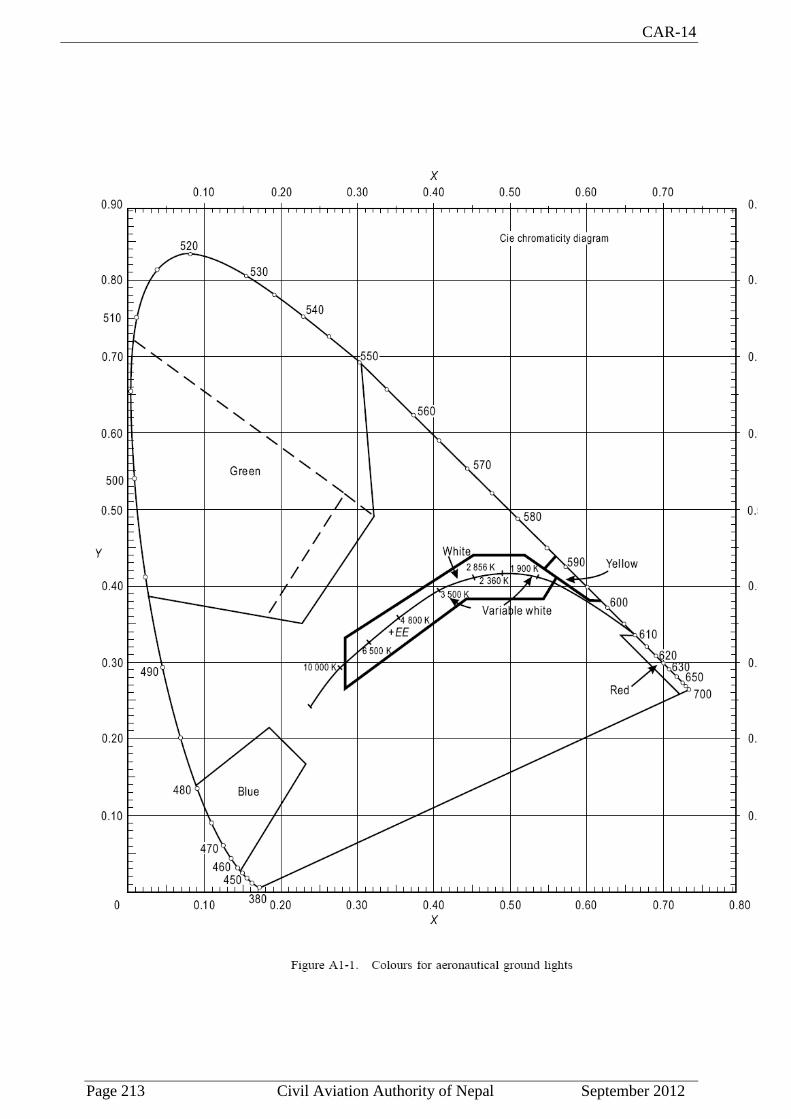
CAR-14
Page 213 Civil Aviation Authority of Nepal September 2012
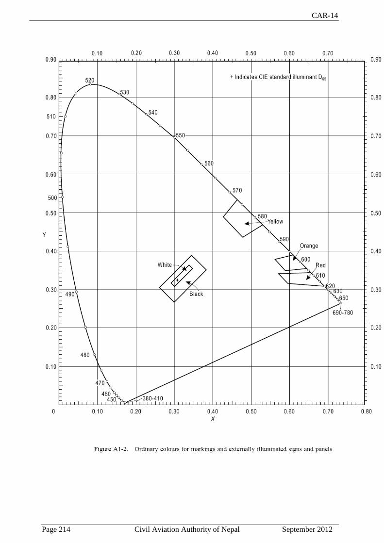
CAR-14
Page 214 Civil Aviation Authority of Nepal September 2012
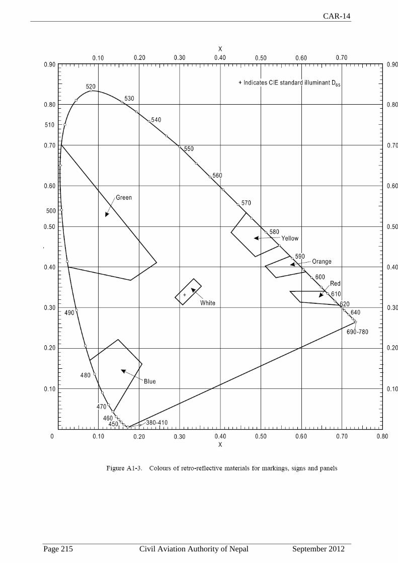
CAR-14
Page 215 Civil Aviation Authority of Nepal September 2012
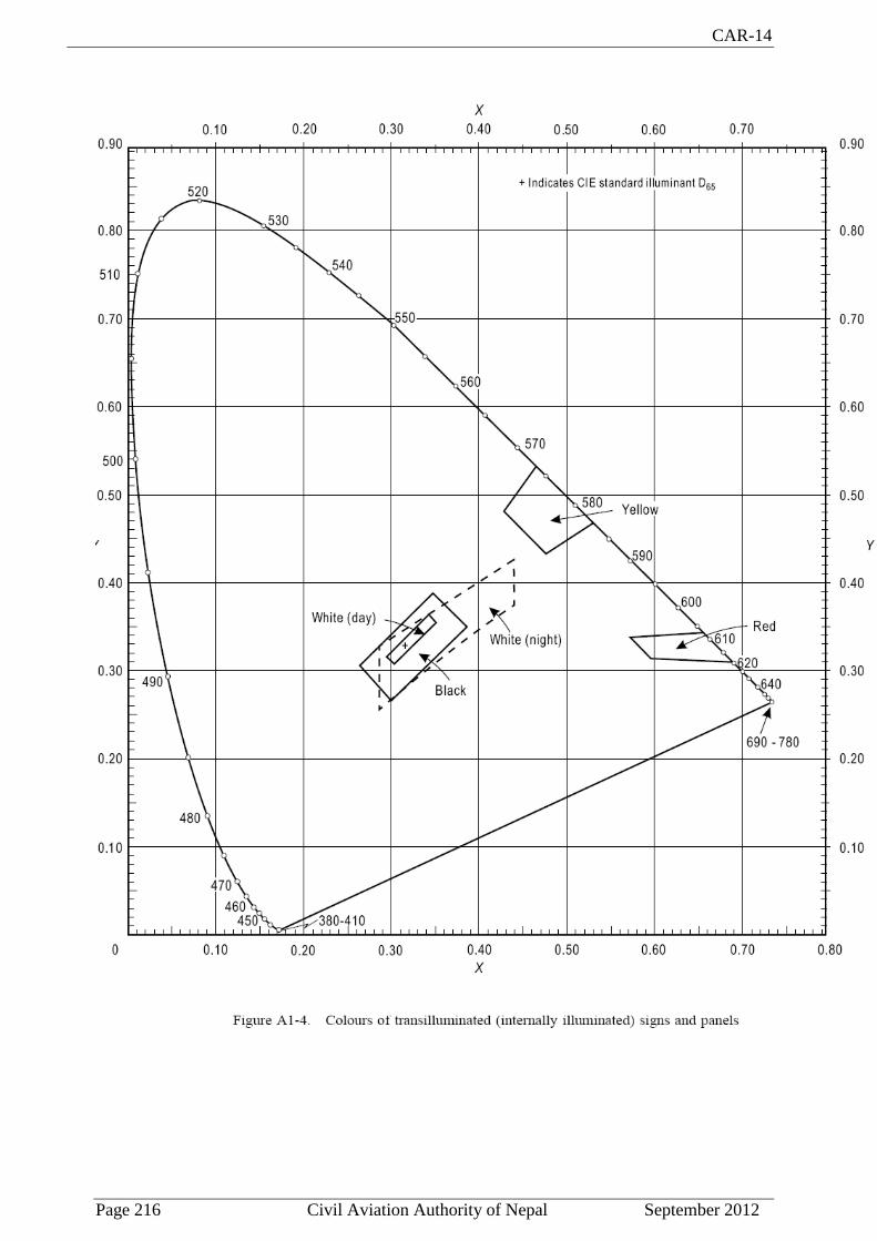
CAR-14
Page 216 Civil Aviation Authority of Nepal September 2012

CAR-14
Page 217 Civil Aviation Authority of Nepal September 2012
APPENDIX- 2
AERONAUTICAL GROUND LIGHT CHARACTERISTICS

CAR-14
Page 218 Civil Aviation Authority of Nepal September 2012

CAR-14
Page 219 Civil Aviation Authority of Nepal September 2012

CAR-14
Page 220 Civil Aviation Authority of Nepal September 2012

CAR-14
Page 221 Civil Aviation Authority of Nepal September 2012

CAR-14
Page 222 Civil Aviation Authority of Nepal September 2012

CAR-14
Page 223 Civil Aviation Authority of Nepal September 2012

CAR-14
Page 224 Civil Aviation Authority of Nepal September 2012

CAR-14
Page 225 Civil Aviation Authority of Nepal September 2012

CAR-14
Page 226 Civil Aviation Authority of Nepal September 2012

CAR-14
Page 227 Civil Aviation Authority of Nepal September 2012
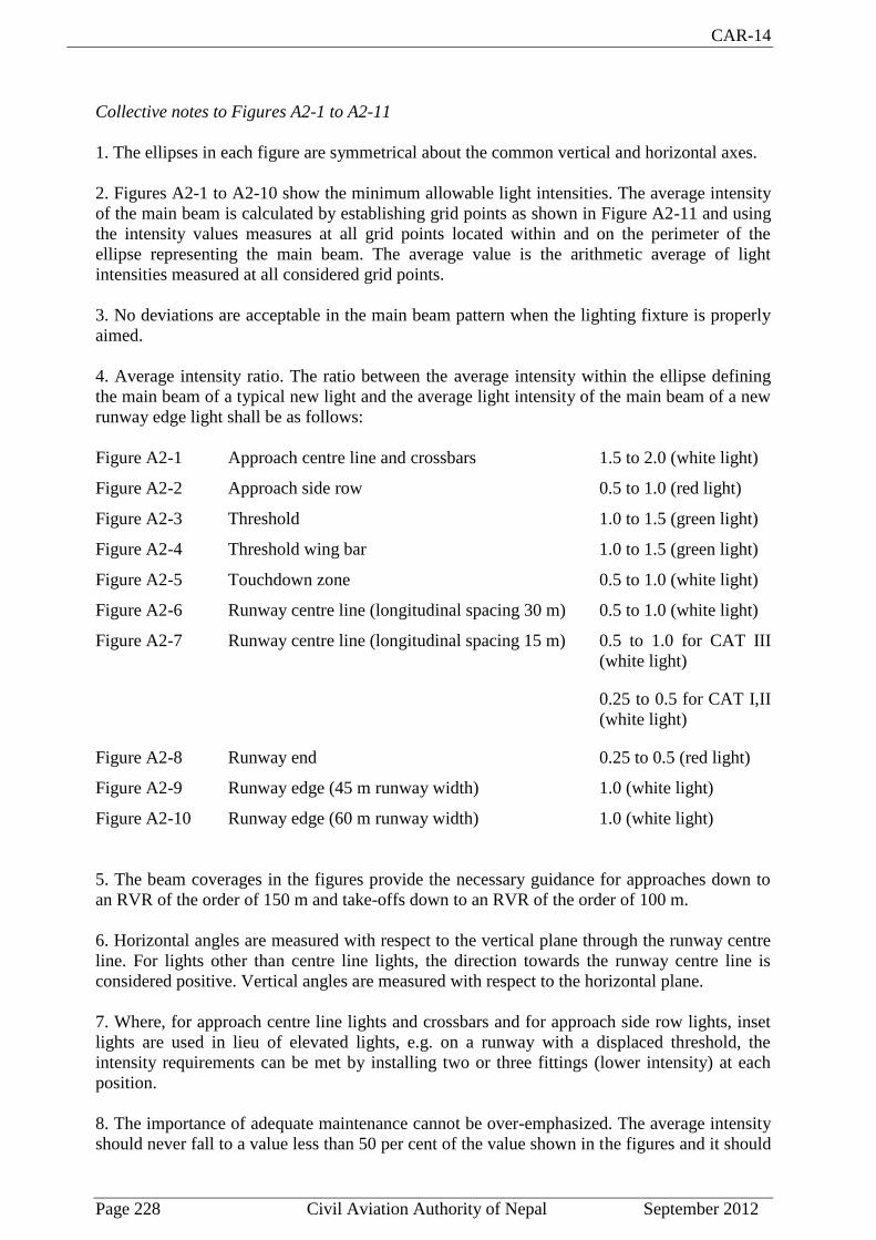
CAR-14
Page 228 Civil Aviation Authority of Nepal September 2012
Collective notes to Figures A2-1 to A2-11
1. The ellipses in each figure are symmetrical about the common vertical and horizontal axes.
2. Figures A2-1 to A2-10 show the minimum allowable light intensities. The average intensity
of the main beam is calculated by establishing grid points as shown in Figure A2-11 and using
the intensity values measures at all grid points located within and on the perimeter of the
ellipse representing the main beam. The average value is the arithmetic average of light
intensities measured at all considered grid points.
3. No deviations are acceptable in the main beam pattern when the lighting fixture is properly
aimed.
4. Average intensity ratio. The ratio between the average intensity within the ellipse defining
the main beam of a typical new light and the average light intensity of the main beam of a new
runway edge light shall be as follows:
Figure A2-1 Approach centre line and crossbars 1.5 to 2.0 (white light)
Figure A2-2 Approach side row 0.5 to 1.0 (red light)
Figure A2-3 Threshold 1.0 to 1.5 (green light)
Figure A2-4 Threshold wing bar 1.0 to 1.5 (green light)
Figure A2-5 Touchdown zone 0.5 to 1.0 (white light)
Figure A2-6 Runway centre line (longitudinal spacing 30 m) 0.5 to 1.0 (white light)
Figure A2-7 Runway centre line (longitudinal spacing 15 m) 0.5 to 1.0 for CAT III
(white light)
0.25 to 0.5 for CAT I,II
(white light)
Figure A2-8 Runway end 0.25 to 0.5 (red light)
Figure A2-9 Runway edge (45 m runway width) 1.0 (white light)
Figure A2-10 Runway edge (60 m runway width) 1.0 (white light)
5. The beam coverages in the figures provide the necessary guidance for approaches down to
an RVR of the order of 150 m and take-offs down to an RVR of the order of 100 m.
6. Horizontal angles are measured with respect to the vertical plane through the runway centre
line. For lights other than centre line lights, the direction towards the runway centre line is
considered positive. Vertical angles are measured with respect to the horizontal plane.
7. Where, for approach centre line lights and crossbars and for approach side row lights, inset
lights are used in lieu of elevated lights, e.g. on a runway with a displaced threshold, the
intensity requirements can be met by installing two or three fittings (lower intensity) at each
position.
8. The importance of adequate maintenance cannot be over-emphasized. The average intensity
should never fall to a value less than 50 per cent of the value shown in the figures and it should
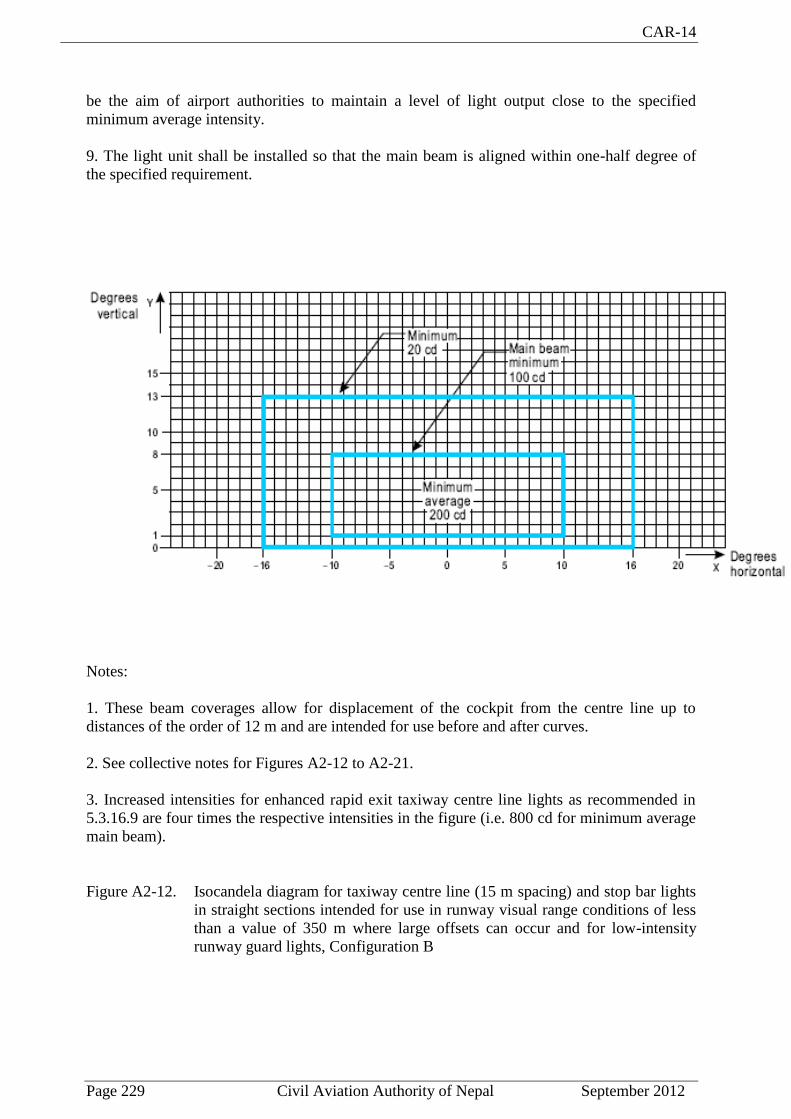
CAR-14
Page 229 Civil Aviation Authority of Nepal September 2012
be the aim of airport authorities to maintain a level of light output close to the specified
minimum average intensity.
9. The light unit shall be installed so that the main beam is aligned within one-half degree of
the specified requirement.
Notes:
1. These beam coverages allow for displacement of the cockpit from the centre line up to
distances of the order of 12 m and are intended for use before and after curves.
2. See collective notes for Figures A2-12 to A2-21.
3. Increased intensities for enhanced rapid exit taxiway centre line lights as recommended in
5.3.16.9 are four times the respective intensities in the figure (i.e. 800 cd for minimum average
main beam).
Figure A2-12. Isocandela diagram for taxiway centre line (15 m spacing) and stop bar lights
in straight sections intended for use in runway visual range conditions of less
than a value of 350 m where large offsets can occur and for low-intensity
runway guard lights, Configuration B
CAR-14
Page 230 Civil Aviation Authority of Nepal September 2012
Notes:
1. These beam coverages are generally satisfactory and cater for a normal displacement of the
cockpit from the centre line of approximately 3 m.
2. See collective notes for Figures A2-12 to A2-21.
Figure A2-13. Isocandela diagram for taxiway centre line (15 m spacing) and stop bar lights
in straight sections intended for use in runway visual range conditions of less
than a value of 350 m

CAR-14
Page 231 Civil Aviation Authority of Nepal September 2012
Notes:
1. Lights on curves to be toed-in 15.75 degrees with respect to the tangent of the curve.
2. See collective notes for Figures A2-12 to A2-21.
Figure A2-14. Isocandela diagram for taxiway centre line (7.5 m spacing) and stop bar lights
in curved sections intended for use in runway visual range conditions of less
than a value of 350 m

CAR-14
Page 232 Civil Aviation Authority of Nepal September 2012
Notes:
1. At locations where high background luminance is usual and where deterioration of light
output resulting from dust, snow and local contamination is a significant factor, the cd-values
should be multiplied by 2.5.
2. Where omnidirectional lights are used they shall comply with the vertical beam
requirements in this figure.
3. See collective notes for Figures A2-12 to A2-21.
Figure A2-15. Isocandela diagram for taxiway centre line (30 m, 60 m spacing) and stop bar
lights in straight sections intended for use in runway visual range conditions
of 350 m or greater

CAR-14
Page 233 Civil Aviation Authority of Nepal September 2012
Notes:
1. Lights on curves to be toed-in 15.75 degrees with respect to the tangent of the curve.
2. At locations where high background luminance is usual and where deterioration of light
output resulting from dust, snow and local contamination is a significant factor, the cd-values
should be multiplied by 2.5.
3. These beam coverages allow for displacement of the cockpit from the centre line up to
distances of the order of 12 m as could occur at the end of curves.
4. See collective notes for Figures A2-12 to A2-21.
Figure A2-16. Isocandela diagram for taxiway centre line (7.5 m, 15 m, 30 m spacing) and
stop bar lights in curved sections intended for use in runway visual range
conditions of 350 m or greater

CAR-14
Page 234 Civil Aviation Authority of Nepal September 2012
Notes:
1. These beam coverages allow for displacement of the cockpit from the centre line up to
distances of the order of 12 m and are intended for use before and after curves.
2. See collective notes for Figures A2-12 to A2-21.
Figure A2-17. Isocandela diagram for high-intensity taxiway centre line (15 m spacing) and
stop bar lights in straight sections intended for use in an advanced surface
movement guidance and control system where higher light intensities are
required and where large offsets can occur

CAR-14
Page 235 Civil Aviation Authority of Nepal September 2012
Notes:
1. These beam coverages are generally satisfactory and cater for a normal displacement of the
cockpit corresponding to the outer main gear wheel on the taxiway edge.
2. See collective notes for Figures A2-12 to A2-21.
Figure A2-18. Isocandela diagram for high-intensity taxiway centre line (15 m spacing) and
stop bar lights in straight sections intended for use in an advanced surface
movement guidance and control system where higher light intensities are
required

CAR-14
Page 236 Civil Aviation Authority of Nepal September 2012
Notes:
1. Lights on curves to be toed-in 17 degrees with respect to the tangent of the curve.
2. See collective notes for Figures A2-12 to A2-21.
Figure A2-19. Isocandela diagram for high-intensity taxiway centre line (7.5 m spacing) and
stop bar lights in curved sections intended for use in an advanced surface
movement guidance and control system where higher light intensities are
required

CAR-14
Page 237 Civil Aviation Authority of Nepal September 2012
Notes:
1. Although the lights flash in normal operation, the light intensity is specified as if the lights
were fixed for incandescent lamps.
2. See collective notes for Figures A2-12 to A2-21.
Figure A2-20. Isocandela diagram for high-intensity runway guard lights, Configuration B
Figure A2-21. Grid points to be used for calculation of average intensity of taxiway centre
line and stop bar lights
CAR-14
Page 238 Civil Aviation Authority of Nepal September 2012
Collective notes to Figures A2-12 to A2-21
1. The intensities specified in Figures A2-12 to A2-20 are in green and yellow light for taxiway
centre line lights, yellow light for runway guard lights and red light for stop bar lights.
2. Figures A2-12 to A2-20 show the minimum allowable light intensities. The average
intensity of the main beam is calculated by establishing grid points as shown in Figure A2-21
and using the intensity values measured at all grid points located within and on the perimeter of
the rectangle representing the main beam. The average value is the arithmetic average of the
light intensities measured at all considered grid points.
3. No deviations are acceptable in the main beam or in the innermost beam, as applicable,
when the lighting fixture is properly aimed.
4. Horizontal angles are measured with respect to the vertical plane through the taxiway centre
line except on curves where they are measured with respect to the tangent to the curve.
5. Vertical angles are measured from the longitudinal slope of the taxiway surface.
6. The importance of adequate maintenance cannot be over-emphasized. The intensity, either
average where applicable or as specified on the corresponding isocandela curves, should never
fall to a value less than 50 per cent of the value shown in the figures, and it should be the aim
of airport authorities to maintain a level of light output close to the specified minimum average
intensity.
7. The light unit shall be installed so that the main beam or the innermost beam, as applicable,
is aligned within one-half degree of the specified requirement.

CAR-14
Page 239 Civil Aviation Authority of Nepal September 2012
Figure A2-22. Light Intensity distribution of T-VASIS and AT-VASIS

CAR-14
Page 240 Civil Aviation Authority of Nepal September 2012

CAR-14
Page 241 Civil Aviation Authority of Nepal September 2012
Notes:
1. Although the lights flash in normal operation, the light intensity is specified as if the lights
were fixed for incandescent lamps.
2. The intensities specified are in yellow light.
Figure A2-24. Isocandela diagram for each light in low-intensity runway guard lights,
Configuration A

CAR-14
Page 242 Civil Aviation Authority of Nepal September 2012
Notes:
1. Although the lights flash in normal operation, the light intensity is specified as if the lights
were fixed for incandescent lamps.
2. The intensities specified are in yellow light.
Figure A2-25. Isocandela diagram for each light in high-intensity runway guard lights,
Configuration A

CAR-14
Page 243 Civil Aviation Authority of Nepal September 2012
APPENDIX-3
MANDATORY INSTRUCTION MARKINGS AND
INFORMATION MARKINGS
Note 1.— See Chapter 5, Sections 5.2.16 and 5.2.17 for specifications on the
application, location and characteristics of mandatory instruction markings and
information markings.
Note 2.— This appendix details the form and proportions of the letters, numbers
and symbols of mandatory instruction markings and information markings on a
20 cm grid.

CAR-14
Page 244 Civil Aviation Authority of Nepal September 2012

CAR-14
Page 245 Civil Aviation Authority of Nepal September 2012

CAR-14
Page 246 Civil Aviation Authority of Nepal September 2012

CAR-14
Page 247 Civil Aviation Authority of Nepal September 2012
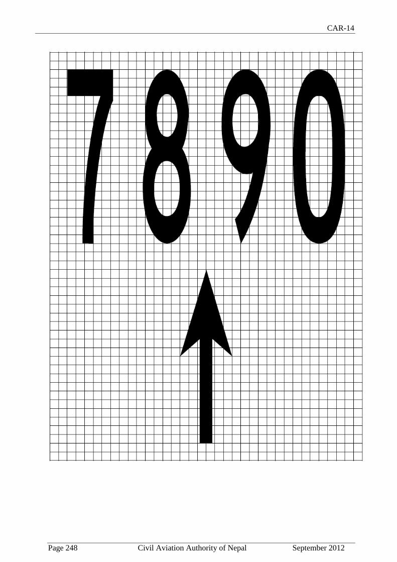
CAR-14
Page 248 Civil Aviation Authority of Nepal September 2012

CAR-14
Page 249 Civil Aviation Authority of Nepal September 2012
APPENDIX -4
REQUIREMENTS CONCERNING DESIGN OF TAXIING GUIDANCE SIGNS
Note.— See Chapter 5, Section 5.4 for specifications on the application, location and
characteristics of signs.
1. Inscription heights shall conform to the following tabulation.
Note.— Where a taxiway location sign is installed in conjunction with a runway designation
sign (see 5.4.3.22), the character size shall be that specified for mandatory instruction signs.
2. Arrow dimensions shall be as follows:
Legend height Stroke
200 mm 32 mm
300 mm 48 mm
400 mm 64 mm
3. Stroke width for single letter shall be as follows:
Legend height Stroke
200 mm 32 mm
300 mm 48 mm
400 mm 64 mm
4. Sign luminance shall be as follows:
a) Where operations are conducted in runway visual range conditions less than a value
of 800 m, average sign luminance shall be at least:
Red 30 cd/m2
Yellow 150 cd/m2

CAR-14
Page 250 Civil Aviation Authority of Nepal September 2012
White 300 cd/m2
b) Where operations are conducted in accordance with 5.4.1.7 b) and c) and 5.4.1.8,
average sign luminance shall be at least:
Red 10 cd/m2
Yellow 50 cd/m2
White 100 cd/m2
Note.— In runway visual range conditions less than a value of 400 m, there will be some
degradation in the performance of signs.
5. The luminance ratio between red and white elements of a mandatory sign shall be between
1:5 and 1:10.
6. The average luminance of the sign is calculated by establishing grid points as shown in
Figure A4-1 and using the luminance values measured at all grid points located within the
rectangle representing the sign.
7. The average value is the arithmetic average of the luminance values measured at all
considered grid points.
Note.— Guidance on measuring the average luminance of a sign is contained in the
Aerodrome Design Manual, Part 4.
8. The ratio between luminance values of adjacent grid points shall not exceed 1.5:1. For areas
on the sign face where the grid spacing is 7.5 cm, the ratio between luminance values of
adjacent grid points shall not exceed 1.25:1. The ratio between the maximum and minimum
luminance value over the whole sign face shall not exceed 5:1.
9. The forms of characters, i.e. letters, numbers, arrows and symbols, shall conform to those
shown in Figure A4-2. The width of characters and the space between individual characters
shall be determined as indicated in Table A4-1.
10. The face height of signs shall be as follows:
Legend height Face height (min)
200 mm 400 mm
300 mm 600 mm
400 mm 800 mm
11. The face width of signs shall be determined using Figure A4-3 except that, where a
mandatory instruction sign is provided on one side of a taxiway only, the face width shall not
be less than:
a) 1.94 m where the code number is 3 or 4; and
b) 1.46 m where the code number is 1 or 2.

CAR-14
Page 251 Civil Aviation Authority of Nepal September 2012
Note.— Additional guidance on determining the face width of a sign is contained in the ICAO
Aerodrome Design Manual, Part 4.
12. Borders
a) The black vertical delineator between adjacent direction signs should have a width
of approximately 0.7 of the stroke width.
b) The yellow border on a stand-alone location sign should be approximately 0.5
stroke width.
13. The colours of signs shall be in accordance with the appropriate specifications in Appendix
1.
Figure A4-1. Grid points for calculating average luminance of a sign
Note 1.— The average luminance of a sign is calculated by establishing grid points on a sign
face showing typical inscriptions and a background of the appropriate colour (red for
mandatory instruction signs and yellow for direction and destination signs) as follows:
a) Starting at the top left corner of the sign face, establish a reference grid point at 7.5
cm from the left edge and the top of the sign face.
b) Create a grid of 15 cm spacing horizontally and vertically from the reference grid
point. Grid points within 7.5 cm of the edge of the sign face shall be excluded.

CAR-14
Page 252 Civil Aviation Authority of Nepal September 2012
c) Where the last point in a row/column of grid points is located between 22.5 cm and
15 cm from the edge of the sign face (but not inclusive), an additional point shall be
added 7.5 cm from this point.
d) Where a grid point falls on the boundary of a character and the background, the
grid point shall be slightly shifted to be completely outside the character.
Note 2.— Additional grid points may be required to ensure that each character includes at
least five evenly spaced grid points.
Note 3.— Where one unit includes two types of signs, a separate grid shall be established for
each type.

CAR-14
Page 253 Civil Aviation Authority of Nepal September 2012

CAR-14
Page 254 Civil Aviation Authority of Nepal September 2012

CAR-14
Page 255 Civil Aviation Authority of Nepal September 2012

CAR-14
Page 256 Civil Aviation Authority of Nepal September 2012

CAR-14
Page 257 Civil Aviation Authority of Nepal September 2012
Figure A4 – 2 (cont.)

CAR-14
Page 258 Civil Aviation Authority of Nepal September 2012
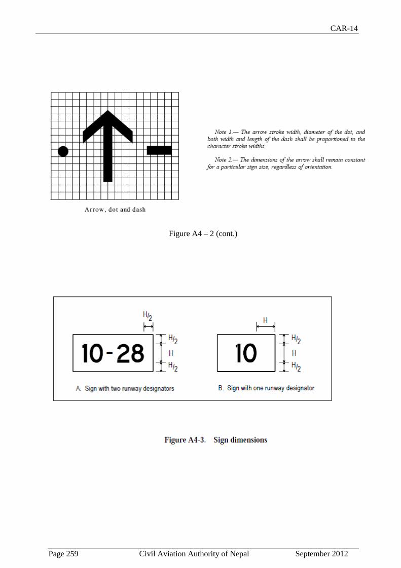
CAR-14
Page 259 Civil Aviation Authority of Nepal September 2012
Figure A4 – 2 (cont.)

CAR-14
Page 260 Civil Aviation Authority of Nepal September 2012

CAR-14
Page 261 Civil Aviation Authority of Nepal September 2012
APPENDIX -5
AERONAUTICAL DATA QUALITY REQUIREMENTS
Table A5-1. Latitude and longitude
Note 1.— See Annex 15, Appendix 8, for graphical illustrations of obstacle data collection
surfaces and criteria used to identify obstacles in the defined areas.

CAR-14
Page 262 Civil Aviation Authority of Nepal September 2012
Note 2.— Implementation of 15 provision 10.6.1.2 concerning the availability, as of 18
November 2010, of obstacle data according to Area 2 and Area 3 specifications would be
facilitated by appropriate advanced planning for the collection and processing of such data.
Note 1.— See Annex 15, Appendix 8, for graphical illustrations of obstacle data collection
surfaces and criteria used to identify obstacles in the defined areas.
Note 2.— Implementation of Annex 15 provision 10.6.1.2 concerning the availability, as of 18
November 2010, of obstacle data according to Area 2 and Area 3 specifications would be
facilitated by appropriate advanced planning for the collection and processing of such data.

CAR-14
Page 263 Civil Aviation Authority of Nepal September 2012
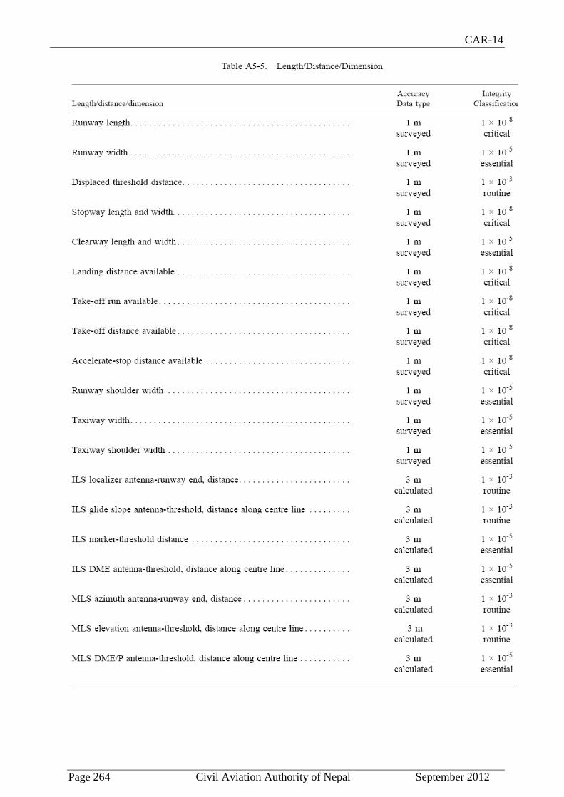
CAR-14
Page 264 Civil Aviation Authority of Nepal September 2012

CAR-14
Page 265 Civil Aviation Authority of Nepal September 2012
APPENDIX -6
LOCATION OF LIGHTS ON OBSTACLES

CAR-14
Page 266 Civil Aviation Authority of Nepal September 2012
Note.— High-intensity obstacle lighting is recommended on structures with a height of more
than 150 m above ground level. If medium-intensity lighting is used, marking will also
be required.
Figure A6-1. Medium-intensity flashing-white obstacle lighting system, Type A

CAR-14
Page 267 Civil Aviation Authority of Nepal September 2012

CAR-14
Page 268 Civil Aviation Authority of Nepal September 2012
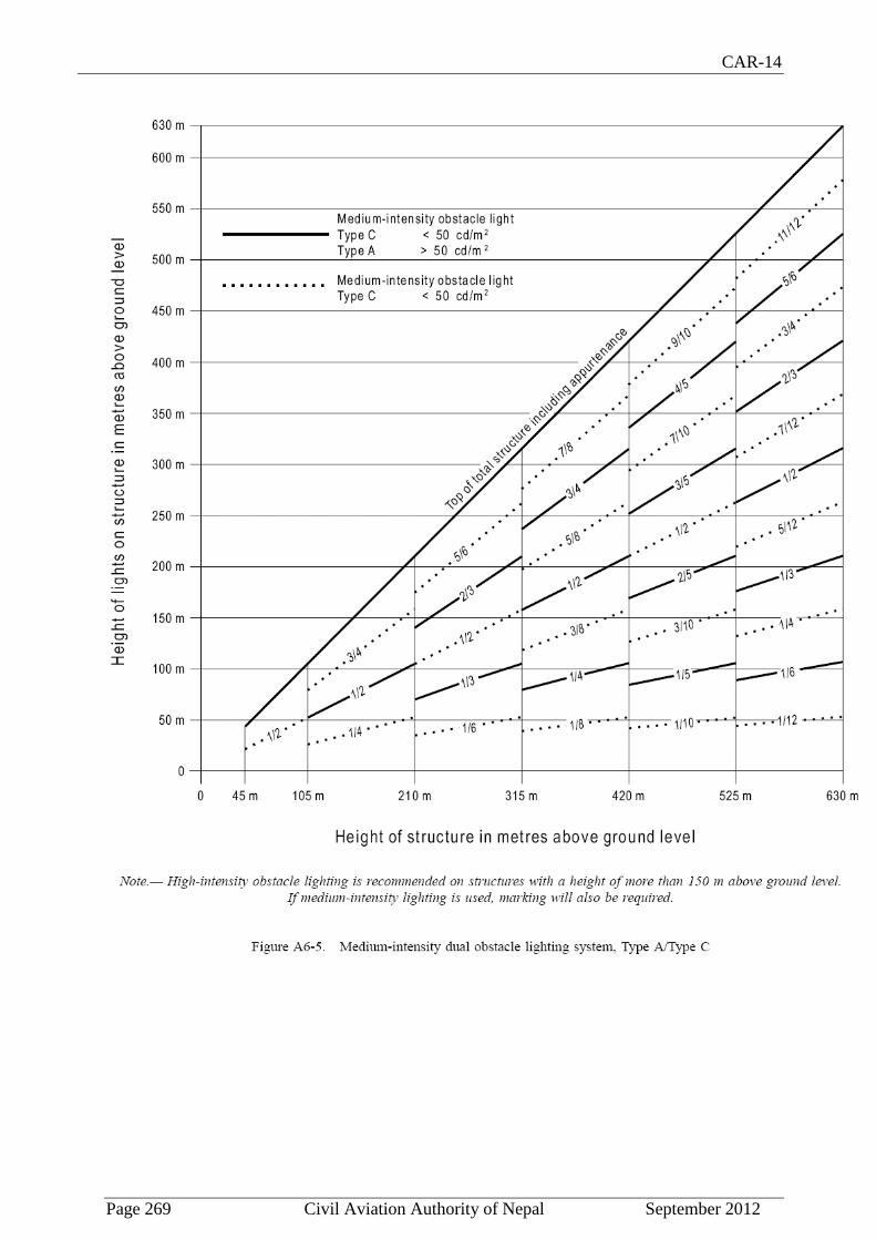
CAR-14
Page 269 Civil Aviation Authority of Nepal September 2012

CAR-14
Page 270 Civil Aviation Authority of Nepal September 2012
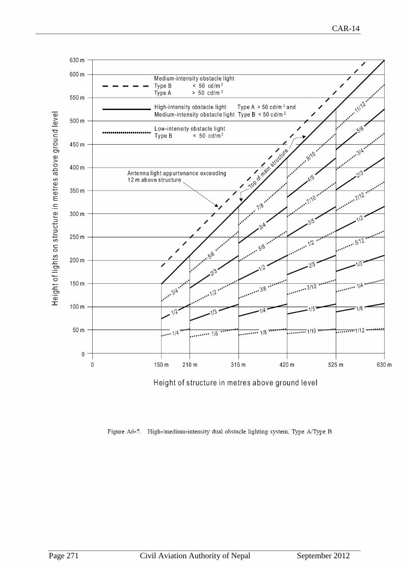
CAR-14
Page 271 Civil Aviation Authority of Nepal September 2012

CAR-14
Page 272 Civil Aviation Authority of Nepal September 2012

CAR-14
Page 273 Civil Aviation Authority of Nepal September 2012
APPENDIX 7.
FRAMEWORK FOR SAFETY MANAGEMENT SYSTEMS
(SMS) (See Chapter 1, 1.5.4)
This appendix specifies the framework for the implementation and maintenance of a safety management system (SMS) by a certified aerodrome. An SMS is a management system for the management of safety by an organization. The framework includes four components and twelve elements representing the minimum requirements for SMS implementation. The implementation of the framework shall be commensurate with the size of the organization and the complexity of the services provided. This appendix also includes a brief description of each element of the framework.
1. Safety policy and objectives
1.1 Management commitment and responsibility 1.2 Safety accountabilities 1.3 Appointment of key safety personnel 1.4 Coordination of emergency response planning 1.5 SMS documentation
2. Safety risk management
2.1 Hazard identification
2.2 Safety risk assessment and mitigation
3. Safety assurance
3.1 Safety performance monitoring and measurement 3.2 The management of change 3.3 Continuous improvement of the SMS
4. Safety promotion
4.1 Training and education
4.2 Safety communication
1. Safety policy and objectives
1.1 Management commitment and responsibility
The certified aerodrome shall define the organization's safety policy which shall be in accordance with international and national requirements, and which shall be signed by the accountable executive of the organization. The safety policy shall reflect organizational commitments regarding safety; shall include a clear statement about the provision of the necessary resources for the implementation of the safety policy; and shall be communicated, with visible endorsement, throughout the organization. The safety policy shall include the safety reporting procedures; shall clearly indicate which types of operational behaviours are
CAR-14
Page 274 Civil Aviation Authority of Nepal September 2012
unacceptable; and shall include the conditions under which disciplinary action would not apply. The safety policy shall be periodically reviewed to ensure it remains relevant and appropriate to the organization.
1.2 Safety accountabilities
The certified aerodrome shall identify the accountable executive who, irrespective of other functions, shall have ultimate responsibility and accountability, on behalf of the certified aerodrome, for the implementation and maintenance of the SMS. The certified aerodrome shall also identify the accountabilities of all members of management, irrespective of other functions, as well as of employees, with respect to the safety performance of the SMS. Safety responsibilities, accountabilities and authorities shall be documented and communicated throughout the organization, and shall include a definition of the levels of management with authority to make decisions regarding safety risk tolerability.
1.3 Appointment of key safety personnel
The certified aerodrome shall identify a safety manager to be the responsible individual and focal point for the implementation and maintenance of an effective SMS.
1.4 Coordination of emergency response planning
The certified aerodrome shall ensure that an emergency response plan that provides for the orderly and efficient transition from normal to emergency operations and the return to normal operations is properly coordinated with the emergency response plans of those organizations it must interface with during the provision of its services.
1.5 SMS documentation
The certified aerodrome shall develop an SMS implementation plan, endorsed by senior management of the organization, that defines the organization's approach to the management of safety in a manner that meets the organization's safety objectives. The organization shall develop and maintain SMS documentation describing the safety policy and objectives, the SMS requirements, the SMS processes and procedures, the accountabilities, responsibilities and authorities for processes and procedures, and the SMS outputs. Also as part of the SMS documentation, the certified aerodrome shall develop and maintain a safety management systems manual (SMSM), to communicate its approach to the management of safety throughout the organization.
2. Safety risk management
2.1 Hazard identification
The certified aerodrome shall develop and maintain a formal process that ensures that hazards in operations are identified. Hazard identification shall be based on a combination of reactive, proactive and predictive methods of safety data collection.
2.2 Safety risk assessment and mitigation
The certified aerodrome shall develop and maintain a formal process that ensures analysis, assessment and control of the safety risks in aerodrome operations.

CAR-14
Page 275 Civil Aviation Authority of Nepal September 2012
3. Safety assurance
3.1 Safety performance monitoring and measurement
The certified aerodrome shall develop and maintain the means to verify the safety performance of the organization and to validate the effectiveness of safety risk controls. The safety performance of the organization shall be verified in reference to the safety performance indicators and safety performance targets of the SMS.
3.2 The management of change
The certified aerodrome shall develop and maintain a formal process to identify changes within the organization which may affect established processes and services; to describe the arrangements to ensure safety performance before implementing changes; and to eliminate or modify safety risk controls that are no longer needed or effective due to changes in the operational environment.
3.3 Continuous improvement of the SMS
The certified aerodrome shall develop and maintain a formal process to identify the causes of substandard performance of the SMS, determine the implications of substandard performance of the SMS in operations, and eliminate or mitigate such causes.
4. Safety promotion
4.1 Training and education
The certified aerodrome shall develop and maintain a safety training programme that ensures that personnel are trained and competent to perform the SMS duties. The scope of the safety training shall be appropriate to each individual's involvement in the SMS.
4.2 Safety communication
The certified aerodrome shall develop and maintain formal means for safety communication that ensures that all personnel are fully aware of the SMS, conveys safety-critical information, and explains why particular safety actions are taken and why safety procedures are introduced or changed.
_________________________________

CAR-14
Page 276 Civil Aviation Authority of Nepal September 2012
ATTACHMENT A.
GUIDANCE MATERIAL SUPPLEMENTARY TO CAR-14, PART 1
1. Number, siting and orientation of runways
Siting and orientation of runways
1.1 Many factors should be taken into account in the determination of the siting and orientation
of runways. Without attempting to provide an exhaustive list of these factors nor an analysis of
their effects, it appears useful to indicate those which most frequently require study. These
factors may be classified under four headings:
1.1.1 Type of operation. Attention should be paid in particular to whether the aerodrome is to
be used in all meteorological conditions or only in visual meteorological conditions, and
whether it is intended for use by day and night, or only by day.
1.1.2 Climatological conditions. A study of the wind distribution should be made to determine
the usability factor. In this regard, the following comments should be taken into account:
a) Wind statistics used for the calculation of the usability factor are normally available
in ranges of speed and direction, and the accuracy of the results obtained depends,
to a large extent, on the assumed distribution of observations within these ranges. In
the absence of any sure information as to the true distribution, it is usual to assume
a uniform distribution since, in relation to the most favourable runway orientations,
this generally results in a slightly conservative for the usability factor.
b) The maximum mean cross-wind components given in Chapter 3, 3.1.3 refer to
normal circumstances. There are some factors which may require that a reduction of
those maximum values be taken into account at a particular aerodrome. These
include:
1) the wide variations which may exist, in handling characteristics and
maximum permissible cross-wind components, among diverse types of
aeroplanes (including future types) within each of the three groups given in
3.1.3;
2) prevalence and nature of gusts;
3) prevalence and nature of turbulence;
4) the availability of a secondary runway;
5) the width of runways;
6) the runway surface conditions — water, snow and ice on the runway
materially reduce the allowable crosswind component; and
7) the strength of the wind associated with the limiting cross-wind component.

CAR-14
Page 277 Civil Aviation Authority of Nepal September 2012
A study should also be made of the occurrence of poor visibility and/or low cloud base.
Account should be taken of their frequency as well as the accompanying wind direction and
speed.
1.1.3 Topography of the aerodrome site, its approaches, and surroundings, particularly:
a) compliance with the obstacle limitation surfaces;
b) current and future land use. The orientation and layout should be selected so as to
protect as far as possible the particularly sensitive areas such as residential, school
and hospital zones from the discomfort caused by aircraft noise. Detailed
information on this topic is provided in the ICAO Airport Planning Manual, Part 2,
and in ICAO Guidance on the Balanced Approach to Aircraft Noise Management
(Doc 9829);
c) current and future runway lengths to be provided;
d) construction costs; and
e) possibility of installing suitable non-visual and visual aids for approach-to-land.
1.1.4 Air traffic in the vicinity of the aerodrome, particularly:
a) proximity of other aerodromes or ATS routes;
b) traffic density; and
c) air traffic control and missed approach procedures.
Number of runways in each direction
1.2 The number of runways to be provided in each direction depends on the number of aircraft
movements to be catered to.
2. Clearways and stopways
2.1 The decision to provide a stopway and/or a clearway as an alternative to an increased
length of runway will depend on the physical characteristics of the area beyond the runway
end, and on the operating performance requirements of the prospective aeroplanes. The
runway, stopway and clearway lengths to be provided are determined by the aeroplane takeoff
performance, but a check should also be made of the landing distance required by the
aeroplanes using the runway to ensure that adequate runway length is provided for landing.
The length of a clearway, however, cannot exceed half the length of take-off run available.
2.2 The aeroplane performance operating limitations require a length which is enough to
ensure that the aeroplane can, after starting a take-off, either be brought safely to a stop or
complete the take-off safely. For the purpose of discussion it is supposed that the runway,
stopway and clearway lengths provided at the aerodrome are only just adequate for the
aeroplane requiring the longest take-off and accelerate-stop distances, taking into account its
take-off mass, runway characteristics and ambient atmospheric conditions. Under these
circumstances there is, for each take-off, a speed, called the decision speed; below this speed,
CAR-14
Page 278 Civil Aviation Authority of Nepal September 2012
the take-off must be abandoned if an engine fails, while above it the take-off must be
completed. A very long take-off run and take-off distance would be required to complete a
take-off when an engine fails before the decision speed is reached, because of the insufficient
speed and the reduced power available. There would be no difficulty in stopping in the
remaining acceleratestop distance available provided action is taken immediately. In these
circumstances the correct course of action would be to abandon the take-off.
2.3 On the other hand, if an engine fails after the decision speed is reached, the aeroplane will
have sufficient speed and power available to complete the take-off safely in the remaining
take-off distance available. However, because of the high speed, there would be difficulty in
stopping the aeroplane in the remaining accelerate-stop distance available.
2.4 The decision speed is not a fixed speed for any aeroplane, but can be selected by the pilot
within limits to suit the accelerate-stop and take-off distance available, aeroplane take-off
mass, runway characteristics, and ambient atmospheric conditions at the aerodrome. Normally,
a higher decision speed is selected as the accelerate-stop distance available increases.
2.5 A variety of combinations of accelerate-stop distances required and take-off distances
required can be obtained to accommodate a particular aeroplane, taking into account the
aeroplane take-off mass, runway characteristics, and ambient atmospheric conditions. Each
combination requires its
particular length of take-off run.
2.6 The most familiar case is where the decision speed is such that the take-off distance
required is equal to the accelerate-stop distance required; this value is known as the balanced
field length. Where stopway and clearway are not provided, these distances are both equal to
the runway length. However, if landing distance is for the moment ignored, runway is not
essential for the whole of the balanced field length, as the take-off run required is, of course,
less than the balanced field length. The balanced field length can, therefore, be provided by a
runway supplemented by an equal length of clearway and stopway, instead of wholly as a
runway. If the runway is used for take-off in both directions, an equal length of clearway and
stopway has to be provided at each runway end. The saving in runway length is, therefore,
bought at the cost of a greater overall length.
2.7 In case economic considerations preclude the provision of stopway and, as a result, only
runway and clearway are to be provided, the runway length (neglecting landing requirements)
should be equal to the accelerate-stop distance required or the take-off run required, whichever
is the greater. The take-off distance available will be the length of the runway plus the length
of clearway.
2.8 The minimum runway length and the maximum stopway or clearway length to be provided
may be determined as follows, from the data in the aeroplane flight manual for the aeroplane
considered to be critical from the viewpoint of runway length requirements:
a) if a stopway is economically possible, the lengths to be provided are those for the
balanced field length. The runway length is the take-off run required or the landing
distance required, whichever is the greater. If the accelerate-stop distance required is
greater than the runway length so determined, the excess may be provided as
stopway, usually at each end of the runway. In addition, a clearway of the same
length as the stopway must also be provided;

CAR-14
Page 279 Civil Aviation Authority of Nepal September 2012
b) if a stopway is not to be provided, the runway length is the landing distance required,
or if it is greater, the accelerate-stop distance required, which corresponds to the
lowest practical value of the decision speed. The excess of the take-off distance
required over the runway length may be provided as clearway, usually at each end of
the runway.
2.9 In addition to the above consideration, the concept of clearways in certain circumstances
can be applied to a situation where the take-off distance required for all engines operating
exceeds that required for the engine failure case.
2.10 The economy of a stopway can be entirely lost if, after each usage, it must be regraded
and compacted. Therefore, it should be designed to withstand at least a certain number of
loadings of the aeroplane which the stopway is intended to serve without inducing structural
damage to the aeroplane.
3. Calculation of declared distances
3.1 The declared distances to be calculated for each runway direction comprise: the take-off
run available (TORA), take-off distance available (TODA), accelerate-stop distance available
(ASDA), and landing distance available (LDA).
3.2 Where a runway is not provided with a stopway or clearway and the threshold is located at
the extremity of the runway, the four declared distances should normally be equal to the length
of the runway, as shown in Figure A-1 (A).
3.3 Where a runway is provided with a clearway (CWY), then the TODA will include the
length of clearway, as shown in Figure A-1 (B).
3.4 Where a runway is provided with a stopway (SWY), then the ASDA will include the length
of stopway, as shown in Figure A-1 (C).
3.5 Where a runway has a displaced threshold, then the LDA will be reduced by the distance
the threshold is displaced, as shown in Figure A-1 (D). A displaced threshold affects only the
LDA for approaches made to that threshold; all declared distances for operations in the
reciprocal direction
are unaffected.
3.6 Figures A-1 (B) through A-1 (D) illustrate a runway provided with a clearway or a stopway
or having a displaced threshold. Where more than one of these features exist, then more than
one of the declared distances will be modified — but the modification will follow the same
principle illustrated. An example showing a situation where all these features exist is shown in
Figure A-1 (E).
3.7 A suggested format for providing information on declared distances is given in Figure A-1
(F). If a runway direction cannot be used for take-off or landing, or both, because it is
operationally forbidden, then this should be declared and the words “not usable” or the
abbreviation “NU” entered.
CAR-14
Page 280 Civil Aviation Authority of Nepal September 2012
4. Slopes on a runway
4.1 Distance between slope changes
The following example illustrates how the distance between slope changes is to be determined
(see Figure A-2):
D for a runway where the code number is 3 should be at least:
15 000 (|x – y| + |y – z|) m
|x – y| being the absolute numerical value of x – y
|y – z| being the absolute numerical value of y – z
Assuming x = + 0.01
Assuming y = – 0.005
Assuming z = + 0.005
then |x – y| = 0.015
|y – z| = 0.01
To comply with the specifications, D should be not less than:
that is,
15 000 (0.015 + 0.01) m,
that is, 15 000 x 0.025 = 375 m
4.2 Consideration of longitudinal and transverse slopes
When a runway is planned that will combine the extreme values for the slopes and changes in
slope permitted under Chapter 3, 3.1.13 to 3.1.19, a study should be made to ensure that the
resulting surface profile will not hamper the operation of aeroplanes.
4.3 Radio altimeter operating area
In order to accommodate aeroplanes making auto-coupled approaches and automatic landings
(irrespective of weather conditions) it is desirable that slope changes be avoided or kept to a
minimum, on a rectangular area at least 300 m long before the threshold of a precision
approach runway. The area should be symmetrical about the extended centre line, 120 m wide.
When special circumstances so warrant, the width may be reduced to no less than 60 m if an
aeronautical study indicates that such reduction would not affect the safety of operations of
aircraft. This is desirable because these aeroplanes are equipped with a radio altimeter for final
height and flare guidance, and when the aeroplane is above the terrain immediately prior to the
threshold, the radio altimeter will begin to provide information to the automatic pilot for
autoflare. Where slope changes cannot be avoided, the rate of change between two consecutive
slopes should not exceed
2 per cent per 30 m.
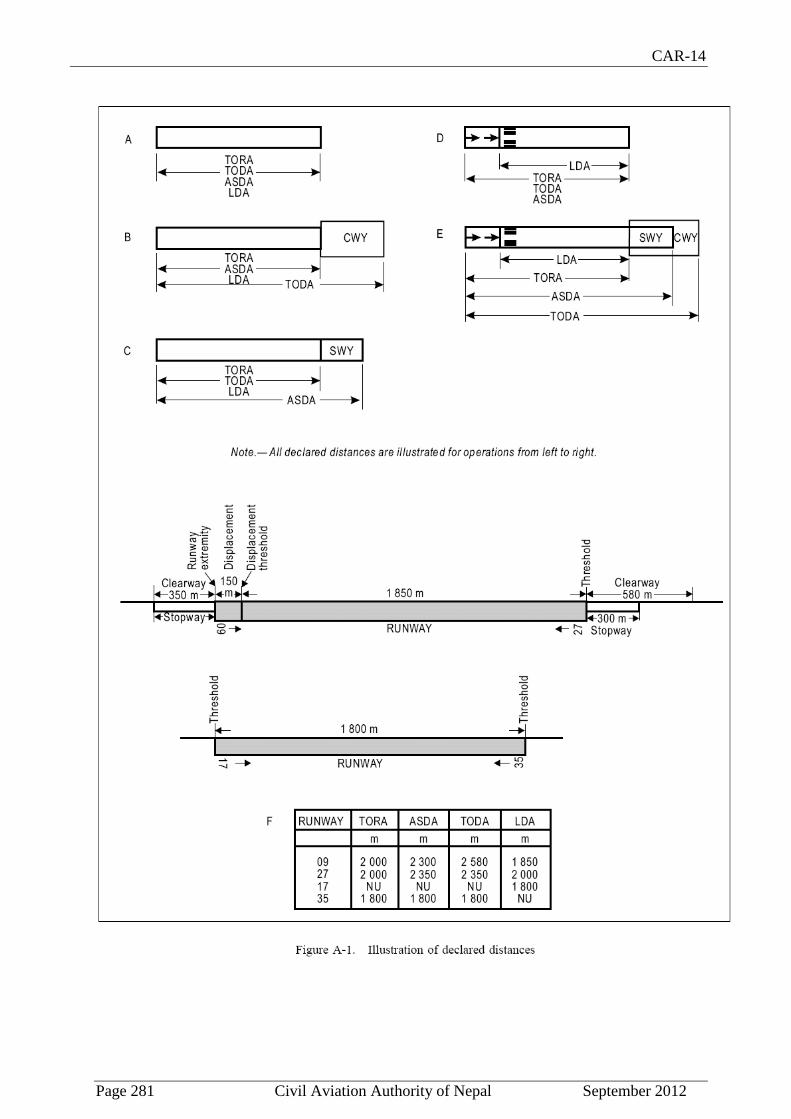
CAR-14
Page 281 Civil Aviation Authority of Nepal September 2012

CAR-14
Page 282 Civil Aviation Authority of Nepal September 2012
5. Runway surface evenness
5.1 In adopting tolerances for runway surface irregularities, the following standard of
construction is achievable for short distances of 3 m and conforms to good engineering
practice:
Except across the crown of a camber or across drainage channels, the finished surface
of the wearing course is to be of such regularity that, when tested with a 3 m
straightedge placed anywhere in any direction on the surface, there is no deviation
greater than 3 mm between the bottom of the straight-edge and the surface of the
pavement anywhere along the straight edge.
5.2 Caution should also be exercised when inserting runway lights or drainage grilles in
runway surfaces to ensure that adequate smoothness of the surface is maintained.
5.3 The operation of aircraft and differential settlement of surface foundations will eventually lead to increases in surface irregularities. Small deviations in the above tolerances will not seriously hamper aircraft operations. In general, isolated irregularities of the order of 2.5 cm to 3 cm over a 45 m distance are tolerable. Although maximum acceptable deviations vary with the type and speed of an aircraft, the limits of acceptable surface irregularities can be estimated to a reasonable extent The following table describes maximum and temporarily acceptable limits. If the maximum limits are exceeded, corrective action should be undertaken as soon as reasonably practicable to improve the ride quality. If the temporarily acceptable limits are exceeded, the portions of the runway that exhibit such roughness should have corrective measures taken immediately if aircraft operations are to be continued.
Surface irregularity Minimum acceptable length of irregularity (m)
3 6 9 12 15 20 30 45 60
Maximum surface irregularity height (or depth) (cm) 3 3.5 4 5 5.5 6 6.5 8 10

CAR-14
Page 283 Civil Aviation Authority of Nepal September 2012
Temporary acceptable surface
irregularity height (or depth) (cm) 3.5 5.5 6.5 7.5 8 9 11 13 15
Note that "surface irregularity" is defined herein to mean isolated surface elevation deviations that do not lie along a uniform slope through any given section of a runway. For the purposes of this concern, a "section of a runway" is defined herein to mean a segment of a runway throughout which a continuing general uphill, downhill or flat slope is prevalent. The length of this section is generally between 30 and 60 metres, and can be greater, depending on the longitudinal profile and the condition of the pavement
5.4 Figure A-3 illustrates a comparison of the surface roughness criteria with those developed by the United States Federal Aviation Administration.
5.5 Deformation of the runway with time may also increase the possibility of the formation of
water pools. Pools as shallow as approximately 3 mm in depth, particularly if they are located
where they are likely to be encountered at high speed by landing aeroplanes, can induce
aquaplaning, which can then be sustained on a wet runway by a much shallower depth of
water. Improved guidance regarding the significant length and depth of pools relative to
aquaplaning is the subject of further research. It is, of course, especially necessary to prevent
pools from forming whenever there is a possibility that they might become frozen.
6. Determining and expressing the friction characteristics of snow- and ice-covered
paved surfaces
6.1 There is an operational need for reliable and uniform information concerning the friction
characteristics of ice- and snow-covered runways. Accurate and reliable indications of surface
friction characteristics can be obtained by friction measuring devices; however, further
experience is required to correlate the results obtained by such equipment with aircraft
performance, owing to the many variables involved, such as: aircraft mass, speed, braking
mechanism, tire and undercarriage characteristics.
6.2 The friction coefficient should be measured if a runway is covered wholly or partly by
snow or ice and repeated as conditions change. Friction measurements and/or braking action
assessments on surfaces other than runways should be made when an unsatisfactory friction
condition can be expected on such surfaces.
6.3 The measurement of the friction coefficient provides the best basis for determining surface
friction conditions. The value of surface friction should be the maximum value which occurs
when a wheel is slipping but still rolling. Various friction measuring devices may be used. As
there is an operational need for uniformity in the method of assessing and reporting runway
friction conditions, the measurements should preferably be made with equipment which
provides continuous measuring of the maximum friction along the entire runway. Measuring
techniques and information on limitations of the various friction measuring devices and
precautions to be observed are given in the Airport Services Manual, Part 2.
6.4 A chart, based on results of tests conducted on selected ice- or snow-covered surfaces,
showing the correlation between certain friction measuring devices on ice- or snow-covered
surfaces is presented in the Airport Services Manual, Part 2.
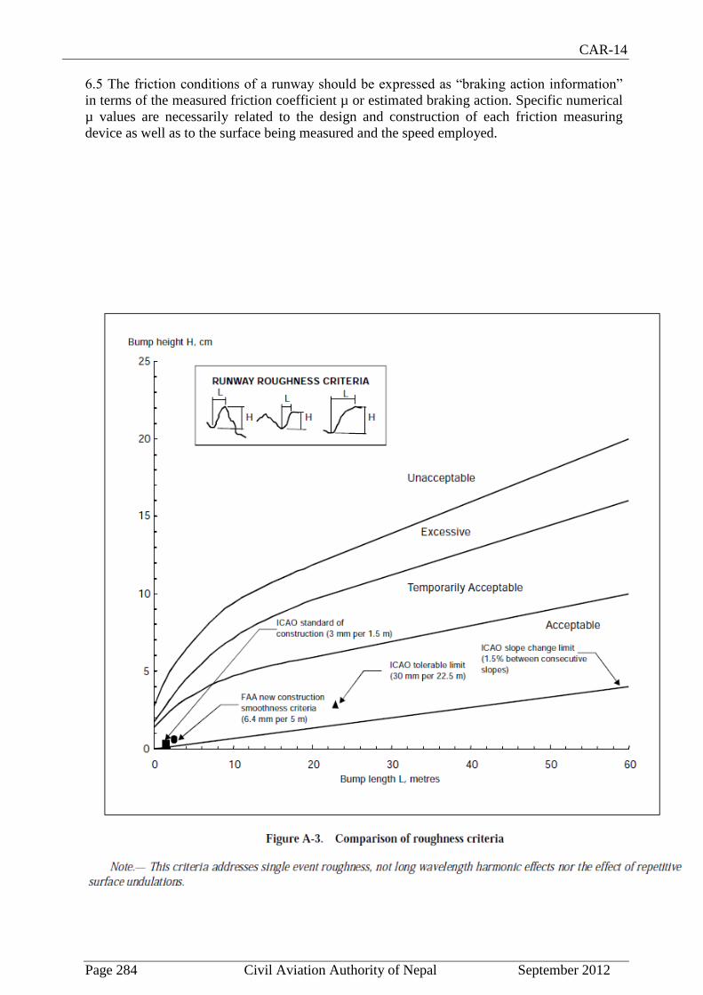
CAR-14
Page 284 Civil Aviation Authority of Nepal September 2012
6.5 The friction conditions of a runway should be expressed as “braking action information”
in terms of the measured friction coefficient µ or estimated braking action. Specific numerical
µ values are necessarily related to the design and construction of each friction measuring
device as well as to the surface being measured and the speed employed.
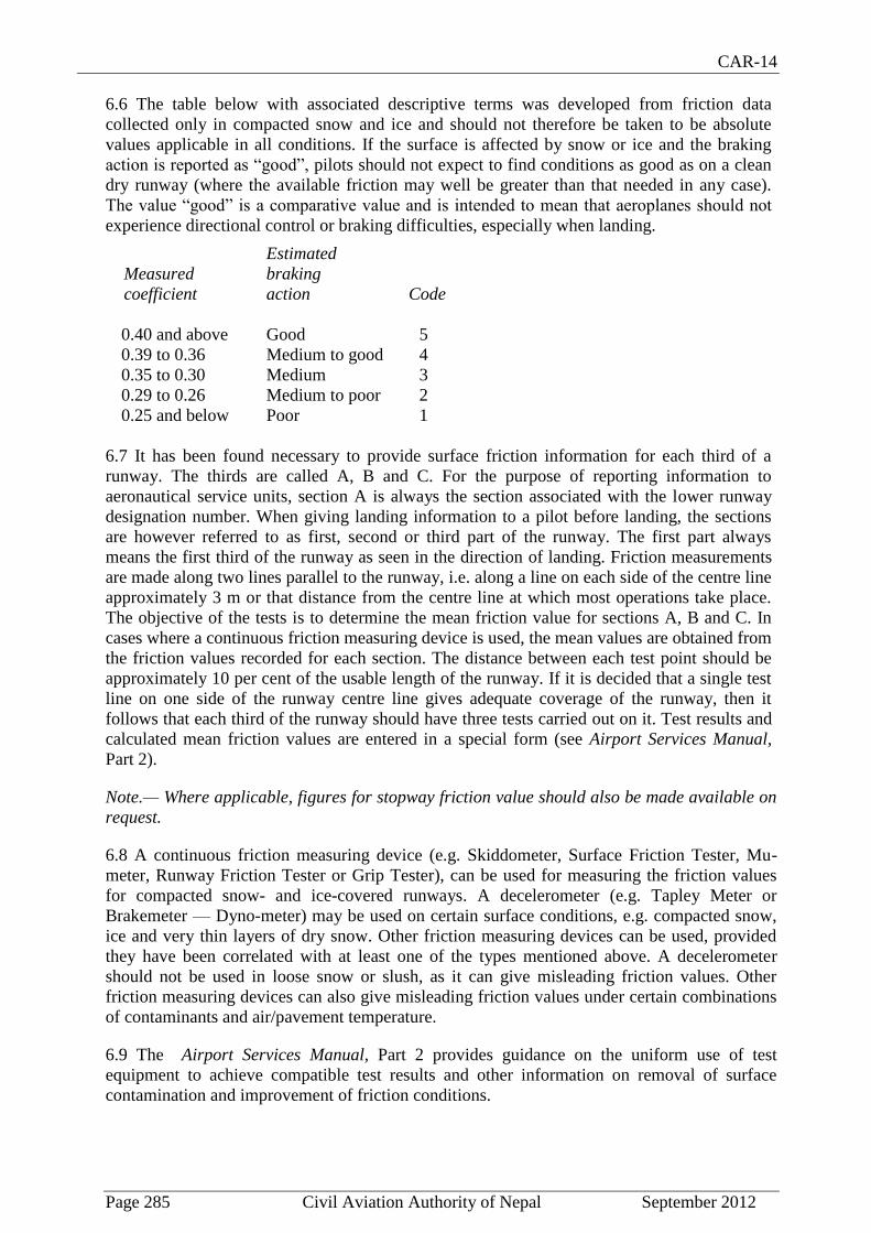
CAR-14
Page 285 Civil Aviation Authority of Nepal September 2012
6.6 The table below with associated descriptive terms was developed from friction data
collected only in compacted snow and ice and should not therefore be taken to be absolute
values applicable in all conditions. If the surface is affected by snow or ice and the braking
action is reported as “good”, pilots should not expect to find conditions as good as on a clean
dry runway (where the available friction may well be greater than that needed in any case).
The value “good” is a comparative value and is intended to mean that aeroplanes should not
experience directional control or braking difficulties, especially when landing.
Estimated
Measured braking
coefficient action Code
0.40 and above Good 5
0.39 to 0.36 Medium to good 4
0.35 to 0.30 Medium 3
0.29 to 0.26 Medium to poor 2
0.25 and below Poor 1
6.7 It has been found necessary to provide surface friction information for each third of a
runway. The thirds are called A, B and C. For the purpose of reporting information to
aeronautical service units, section A is always the section associated with the lower runway
designation number. When giving landing information to a pilot before landing, the sections
are however referred to as first, second or third part of the runway. The first part always
means the first third of the runway as seen in the direction of landing. Friction measurements
are made along two lines parallel to the runway, i.e. along a line on each side of the centre line
approximately 3 m or that distance from the centre line at which most operations take place.
The objective of the tests is to determine the mean friction value for sections A, B and C. In
cases where a continuous friction measuring device is used, the mean values are obtained from
the friction values recorded for each section. The distance between each test point should be
approximately 10 per cent of the usable length of the runway. If it is decided that a single test
line on one side of the runway centre line gives adequate coverage of the runway, then it
follows that each third of the runway should have three tests carried out on it. Test results and
calculated mean friction values are entered in a special form (see Airport Services Manual,
Part 2).
Note.— Where applicable, figures for stopway friction value should also be made available on
request.
6.8 A continuous friction measuring device (e.g. Skiddometer, Surface Friction Tester, Mu-
meter, Runway Friction Tester or Grip Tester), can be used for measuring the friction values
for compacted snow- and ice-covered runways. A decelerometer (e.g. Tapley Meter or
Brakemeter — Dyno-meter) may be used on certain surface conditions, e.g. compacted snow,
ice and very thin layers of dry snow. Other friction measuring devices can be used, provided
they have been correlated with at least one of the types mentioned above. A decelerometer
should not be used in loose snow or slush, as it can give misleading friction values. Other
friction measuring devices can also give misleading friction values under certain combinations
of contaminants and air/pavement temperature.
6.9 The Airport Services Manual, Part 2 provides guidance on the uniform use of test
equipment to achieve compatible test results and other information on removal of surface
contamination and improvement of friction conditions.

CAR-14
Page 286 Civil Aviation Authority of Nepal September 2012
7. Determination of friction characteristics of wet paved runways
7.1 The friction of a wet paved runway should be measured to:
a) verify the friction characteristics of new or resurfaced paved runways when wet
(Chapter 3, 3.1.24);
b) assess periodically the slipperiness of paved runways when wet (Chapter 10,
10.2.3);
c) determine the effect on friction when drainage characteristics are poor (Chapter 10,
10.2.6); and
d) determine the friction of paved runways that become slippery under unusual
conditions (Chapter 2, 2.9.8).
7.2 Runways should be evaluated when first constructed or after resurfacing to determine the
wet runway surface friction characteristics. Although it is recognized that friction reduces with
use, this value will represent the friction of the relatively long central portion of the runway
that is uncontaminated by rubber deposits from aircraft operations and is therefore of
operational value. Evaluation tests should be made on clean surfaces. If it is not possible to
clean a surface before testing, then for purposes of preparing an initial report a test could be
made on a portion of clean surface in the central part of the runway.
7.3 Friction tests of existing surface conditions should be taken periodically in order to identify
runways with low friction when wet. A State should define what minimum friction level it
considers acceptable before a runway is classified as slippery when wet and publish this value
in the State’s aeronautical information publication (AIP). When the friction of a runway is
found to be below this reported value, then such information should be promulgated by
NOTAM. The State should also establish a maintenance planning level, below which,
appropriate corrective maintenance action should be initiated to improve the friction. However,
when the friction characteristics for either the entire runway or a portion thereof are below the
minimum friction level, corrective maintenance action must be taken without delay. Friction
measurements should be taken at intervals that will ensure identification of runways in need of
maintenance or special surface treatment before the condition becomes serious. The time
interval between measurements will depend on factors such as: aircraft type and frequency of
usage, climatic conditions, pavement type, and pavement service and maintenance
requirements.
7.4 For uniformity and to permit comparison with other runways, friction tests of existing, new
or resurfaced runways should be made with a continuous friction measuring device provided
with a smooth tread tire. The device should have a capability of using self-wetting features to
enable measurements of the friction characteristics of the surface to be made at a water depth
of at least 1 mm.
7.5 When it is suspected that the friction characteristics of a runway may be reduced because
of poor drainage, owing to inadequate slopes or depressions, then an additional test should be
made, but this time under natural conditions representative of a local rain. This test differs
from the previous one in that water depths in the poorly cleared areas are normally greater in a
local rain condition. The test results are thus more apt to identify problem areas having low
friction values that could induce aquaplaning than the previous test. If circumstances do not

CAR-14
Page 287 Civil Aviation Authority of Nepal September 2012
permit tests to be conducted during natural conditions representative of a rain, then this
condition may be simulated.
7.6 Even when the friction has been found to be above the level set by the State to define a
slippery runway, it may be known that under unusual conditions, such as after a long dry
period, the runway may have become slippery. When such a condition is known to exist, then a
friction measurement should be made as soon as it is suspected that the runway may have
become slippery.
7.7 When the results of any of the measurements identified in 7.3 through 7.6 indicate that only
a particular portion of a runway surface is slippery, then action to promulgate this information
and, if appropriate, take corrective action is equally important.
7.8 When conducting friction tests on wet runways, it is important to note that, unlike
compacted snow and ice conditions, in which there is very limited variation of the friction
coefficient with speed, a wet runway produces a drop in friction with an increase in speed.
However, as the speed increases, the rate at which the friction is reduced becomes less. Among
the factors affecting the friction coefficient between the tire and the runway surface, texture is
particularly important. If the runway has a good macro-texture allowing the water to escape
beneath the tire, then the friction value will be less affected by speed. Conversely, a low
macro-texture surface will produce a larger drop in friction with increase in speed.
Accordingly, when testing runways to determine their friction characteristics and whether
maintenance action is necessary to improve it, a speed high enough to reveal these
friction/speed variations should be used.
7.9 CAR-14 Part 1 requires to specify two friction levels as follows:
a) a maintenance friction level below which corrective maintenance action should be
initiated; and
b) a minimum friction level below which information that a runway may be slippery
when wet should be made available.
Furthermore, CAR-14 Part 1 establish criteria for the friction characteristics of new or
resurfaced runway surfaces. Table A-1 provides guidance on establishing the design objective
for new runway surfaces and maintenance planning and minimum friction levels for runway
surfaces in use.
7.10 The friction values given above are absolute values and are intended to be applied without
any tolerance. These values were developed from a research study conducted in a State. The
two friction measuring tires mounted on the Mumeter were smooth tread and had a special
rubber formulation, i.e. Type A. The tires were tested at a 15 degree included angle of
alignment along the longitudinal axis of the trailer. The single friction measuring tires mounted
on the Skiddometer, Surface Friction Tester, Runway Friction Tester and TATRA were smooth
tread and used the same rubber formulation, i.e. Type B. The GRIPTESTER was tested with a
single smooth tread tire having the same rubber formulation as Type B but the size was
smaller, i.e. Type C. The specifications of these tires (i.e. Types A, B and C) are contained in
the ICAO Airport Services Manual, Part 2. Friction measuring devices using rubber
formulation, tire tread/groove patterns, water depth, tire pressures, or test speeds different from
those used in the programme described above, cannot be directly equated with the friction
values given in the table. The values in columns (5), (6) and (7) are averaged values

CAR-14
Page 288 Civil Aviation Authority of Nepal September 2012
representative of the runway or significant portion thereof. It is considered desirable to test the
friction characteristics of a paved runway at more than one speed.
7.11 Other friction measuring devices can be used, provided they have been correlated with at
least one test equipment mentioned above. The ICAO Airport Services Manual, Part 2 provides
guidance on the methodology for determining the friction values corresponding to the design
objective, maintenance planning level and minimum friction level for a friction tester not
identified in the above table.
8. Strips
8.1 Shoulders
8.1.1 The shoulder of a runway or stopway should be prepared or constructed so as to
minimize any hazard to an aeroplane running off the runway or stopway. Some guidance is
given in the following paragraphs on certain special problems which may arise, and on the
further question of
measures to avoid the ingestion of loose stones or other objects by turbine engines.
8.1.2 In some cases, the bearing strength of the natural ground in the strip may be sufficient,
without special preparation, to meet the requirements for shoulders. Where special preparation
is necessary, the method used will depend on local soil conditions and the mass of the
aeroplanes the runway is intended to serve. Soil tests will help in determining the best method
of improvement (e.g. drainage, stabilization, surfacing, light paving).
8.1.3 Attention should also be paid when designing shoulders to prevent the ingestion of stones
or other objects by turbine engines. Similar considerations apply here to those which are
discussed for the margins of taxiways in the Aerodrome Design Manual, Part 2, both as to the
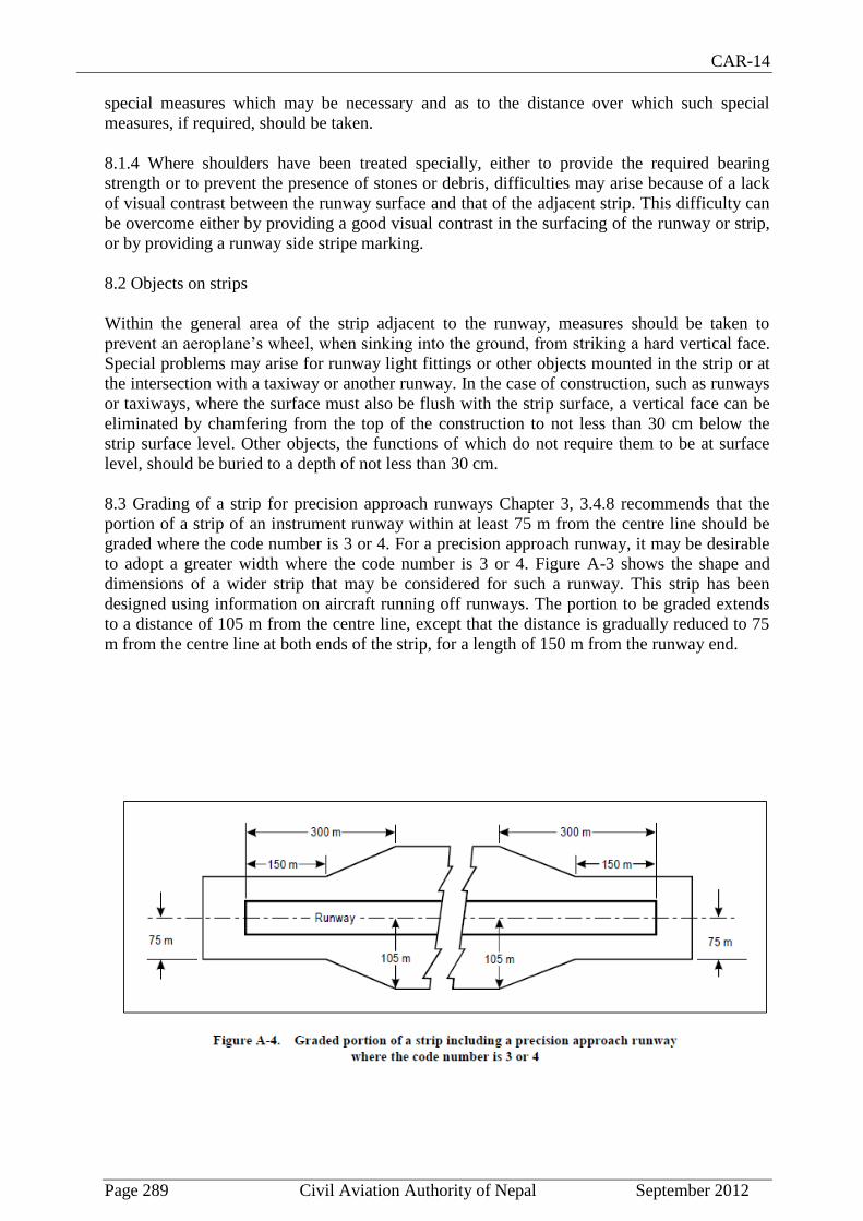
CAR-14
Page 289 Civil Aviation Authority of Nepal September 2012
special measures which may be necessary and as to the distance over which such special
measures, if required, should be taken.
8.1.4 Where shoulders have been treated specially, either to provide the required bearing
strength or to prevent the presence of stones or debris, difficulties may arise because of a lack
of visual contrast between the runway surface and that of the adjacent strip. This difficulty can
be overcome either by providing a good visual contrast in the surfacing of the runway or strip,
or by providing a runway side stripe marking.
8.2 Objects on strips
Within the general area of the strip adjacent to the runway, measures should be taken to
prevent an aeroplane’s wheel, when sinking into the ground, from striking a hard vertical face.
Special problems may arise for runway light fittings or other objects mounted in the strip or at
the intersection with a taxiway or another runway. In the case of construction, such as runways
or taxiways, where the surface must also be flush with the strip surface, a vertical face can be
eliminated by chamfering from the top of the construction to not less than 30 cm below the
strip surface level. Other objects, the functions of which do not require them to be at surface
level, should be buried to a depth of not less than 30 cm.
8.3 Grading of a strip for precision approach runways Chapter 3, 3.4.8 recommends that the
portion of a strip of an instrument runway within at least 75 m from the centre line should be
graded where the code number is 3 or 4. For a precision approach runway, it may be desirable
to adopt a greater width where the code number is 3 or 4. Figure A-3 shows the shape and
dimensions of a wider strip that may be considered for such a runway. This strip has been
designed using information on aircraft running off runways. The portion to be graded extends
to a distance of 105 m from the centre line, except that the distance is gradually reduced to 75
m from the centre line at both ends of the strip, for a length of 150 m from the runway end.
CAR-14
Page 290 Civil Aviation Authority of Nepal September 2012
9. Runway end safety areas
9.1 Where a runway end safety area is provided in accordance with Chapter 3, consideration
should be given to providing an area long enough to contain overruns and undershoots
resulting from a reasonably probable combination of adverse operational factors. On a
precision approach runway, the ILS localizer is normally the first upstanding obstacle, and the
runway end safety area should extend up to this facility. In other circumstances and on a non-
precision approach or non-instrument runway, the first upstanding obstacle may be a road, a
railroad or other constructed or natural feature. In such circumstances, the runway end safety
area should extend as far as the obstacle.
9.2 Where provision of a runway end safety area may involve encroachment in areas where it
would be particularly prohibitive to implement, and the appropriate authority considers a
runway end safety area essential, consideration may have to be given to reducing some of the
declared distances.
10. Location of threshold
10.1 General
10.1.1 The threshold is normally located at the extremity of a runway, if there are no obstacles
penetrating above the approach surface. In some cases, however, due to local conditions it may
be desirable to displace the threshold permanently (see below). When studying the location of
a threshold, consideration should also be given to the height of the ILS reference datum and/or
MLS approach reference datum and the determination of the obstacle clearance limits.
(Specifications concerning the height of the ILS reference datum and MLS approach reference
datum are given in Annex 10, Part 1.)
10.1.2 In determining that no obstacle penetrate above the approach surface, account should be
taken of mobile objects (vehicles on roads, trains, etc.) at least within that portion of the
approach area within 1 200 m longitudinally from the threshold and of an overall width of not
less than 150 m.
10.2 Displaced threshold
10.2.1 If an object extends above the approach surface and the object cannot be removed,
consideration should be given to displacing the threshold permanently.
10.2.2 To meet the obstacle limitation objectives of Chapter 4, the threshold should ideally be
displaced down the runway for the distance necessary to provide that the approach surface is
cleared of obstacles.
10.2.3 However, displacement of the threshold from the runway extremity will inevitably
cause reduction of the landing distance available, and this may be of greater operational
significance than penetration of the approach surface by marked and lighted obstacles. A
decision to displace the threshold, and the extent of such displacement, should therefore have
regard to an optimum balance between the considerations of clear approach surfaces and
adequate landing distance. In deciding this question, account will need to be taken of the types
of aeroplanes which the runway is intended to serve, the limiting visibility and cloud base
conditions under which the runway will be used, the position of the obstacles in relation to the

CAR-14
Page 291 Civil Aviation Authority of Nepal September 2012
threshold and extended centre line and, in the case of a precision approach runway, the
significance of the obstacles to the determination of the obstacle clearance limit.
10.2.4 Notwithstanding the consideration of landing distance available, the selected position
for the threshold should not be such that the obstacle-free surface to the threshold is steeper
than 3.3 per cent where the code number is 4 or steeper than 5 per cent where the code number
is 3.
10.2.5 In the event of a threshold being located according to the criteria for obstacle-free
surfaces in the preceding paragraph, the obstacle marking requirements of Chapter 6 should
continue to be met in relation to the displaced threshold.
10.2.4 Depending on the length of the displacement, the RVR at the threshold could differ from that at the beginning of the runway for take-offs. The use of red runway edge lights with photometric intensities lower than the nominal value of 10 000 cd for white lights increases that phenomenon. The impact of a displaced threshold on take-off minima should be assessed by the appropriate authority.
10.2.5 Provisions CAR-14, Part 1, regarding marking and lighting of displaced thresholds and some operational recommendations can be found in 5.2.4.9, 5.2.4.10, 5.3.5.5, 5.3.8.1, 5.3.9.7, 5.3.10.3, 5.3.10.7 and 5.3.12.6.
11. Approach lighting systems
11.1 Types and characteristics
11.1.1 The specifications in this volume provide for the basic characteristics for simple and
precision approach lighting systems. For certain aspects of these systems, some latitude is
permitted, for example, in the spacing between centre line lights and crossbars. The approach
lighting patterns that have been generally adopted are shown in Figures A-5 and A-6. A
diagram of the inner 300 m of the precision approach category II and III lighting system is
shown in Figure 5-14.
11.1.2 The approach lighting configuration is to be provided irrespective of the location of the
threshold, i.e. whether the threshold is at the extremity of the runway or displaced from the
runway extremity. In both cases, the approach lighting system should extend up to the
threshold. However, in the case of a displaced threshold, inset lights are used from the runway
extremity up to the threshold to obtain the specified configuration. These inset lights are
designed to satisfy the structural requirements specified in Chapter 5, 5.3.1.9, and the
photometric requirements specified in Appendix 2, Figure A2-1 or A2-2.
11.1.3 Flight path envelopes to be used in designing the lighting are shown in Figure A-5.
11.2 Installation tolerances
Horizontal
11.2.1 The dimensional tolerances are shown in Figure A-7.

CAR-14
Page 292 Civil Aviation Authority of Nepal September 2012
11.2.2 The centre line of an approach lighting system should be as coincident as possible with
the extended centre line of the runway with a maximum tolerance of + or – 15´.
11.2.3 The longitudinal spacing of the centre line lights should be such that one light (or group
of lights) is located in the centre of each crossbar, and the intervening centre line lights are
spaced as evenly as practicable between two crossbars or a crossbar and a threshold.
11.2.4 The crossbars and barrettes should be at right angles to the centre line of the approach
lighting system with a tolerance of + or - 30′, if the pattern in Figure A-7 (A) is adopted or +
or - 2°, if Figure A-7 (B) is adopted.
11.2.5 When a crossbar has to be displaced from its standard position, any adjacent crossbar
should, where possible, be displaced by appropriate amounts in order to reduce the differences
in the crossbar spacing.
11.2.6 When a crossbar in the system shown in Figure A-6 (A) is displaced from its standard
position, its overall length should be adjusted so that it remains one-twentieth of the actual
distance of the crossbar from the point of origin. It is not necessary, however, to adjust the
standard 2.7 m spacing between the crossbar lights, but the crossbars should be kept
symmetrical about the centre line of the approach lighting.
Vertical
11.2.7 The ideal arrangement is to mount all the approach lights in the horizontal plane passing
through the threshold (see Figure A-7), and this should be the general aim as far as local
conditions permit. However, buildings, trees, etc., should not obscure the lights from the view
of a pilot who is assumed to be 1° below the electronic glide path in the vicinity of the outer
marker.
11.2.8 Within a stopway or clearway, and within 150 m of the end of a runway, the lights
should be mounted as near to the ground as local conditions permit in order to minimize risk of
damage to aeroplanes in the event of an overrun or undershoot. Beyond the stopway and
clearway, it is not so
necessary for the lights to be mounted close to the ground and therefore undulations in the
ground contours can be compensated for by mounting the lights on poles of appropriate height.
11.2.9 It is desirable that the lights be mounted so that, asfar as possible, no object within a
distance of 60 m on each side of the centre line protrudes through the plane of the approach
lighting system. Where a tall object exists within 60 m of the centre line and within 1 350 m
from the threshold for a precision approach lighting system, or 900 m for a simple approach
lighting system, it may be advisable to install the lights so that the plane of the outer half of the
pattern clears the top of the object.
11.2.10 In order to avoid giving a misleading impression of the plane of the ground, the lights
should not be mounted below a gradient of 1 in 66 downwards from the threshold to a point
300 m out, and below a gradient of 1 in 40 beyond the 300 m point. For a precision approach
category II and III lighting system, more stringent criteria may be necessary, e.g. negative
slopes not permitted within 450 m of the threshold.

CAR-14
Page 293 Civil Aviation Authority of Nepal September 2012

CAR-14
Page 294 Civil Aviation Authority of Nepal September 2012

CAR-14
Page 295 Civil Aviation Authority of Nepal September 2012
11.2.11 Centre line. The gradients of the centre line in any section (including a stopway or
clearway) should be as small as practicable, and the changes in gradients should be as few and
small as can be arranged and should not exceed 1 in 60. Experience has shown that as one
proceeds outwards from the runway, rising gradients in any section of up to 1 in 66, and falling
gradients of down to 1 in 40, are acceptable.
11.2.12 Crossbars. The crossbar lights should be so arranged as to lie on a straight line passing
through the associated centre line lights, and wherever possible this line should be horizontal.
It is permissible, however, to mount the lights on a transverse gradient not more than 1 in 80, if
this enables crossbar lights within a stopway or clearway to be mounted nearer to the ground
on sites where there is a cross-fall.
11.3 Clearance of obstacles
11.3.1 An area, hereinafter referred to as the light plane, has been established for obstacle
clearance purposes, and all lights of the system are in this plane. This plane is rectangular in
shape and symmetrically located about the approach lighting system’s centre line. It starts at
the threshold and extends 60 m beyond the approach end of the system, and is 120 m wide.
11.3.2 No objects are permitted to exist within the boundaries of the light plane which are
higher than the light plane except as designated herein. All roads and highways are considered
as obstacles extending 4.8 m above the crown of the road, except aerodrome service roads
where all vehicular traffic is under control of the aerodrome authorities and coordinated with
the aerodrome traffic control tower. Railroads, regardless of the amount of traffic, are
considered as obstacles extending 5.4 m above the top of the rails.
11.3.3 It is recognized that some components of electronic landing aids systems, such as
reflectors, antennas, monitors, etc., must be installed above the light plane. Every effort should
be made to relocate such components outside the boundaries of the light plane. In the case of
reflectors and monitors, this can be done in many instances.
11.3.4 Where an ILS localizer is installed within the light plane boundaries, it is recognized
that the localizer, or screen if used, must extend above the light plane. In such cases the height
of these structures should be held to a minimum and they should be located as far from the
threshold as possible. In general the rule regarding permissible heights is 15 cm for each 30 m
the structure is located from the threshold. As an example, if the localizer is located 300 m
from the threshold, the screen will be permitted to extend above the plane of the approach
lighting system by 10 x 15 = 150 cm maximum, but preferably should be kept as low as
possible consistent with proper operation of the ILS.
11.3.5 In locating an MLS azimuth antenna the guidance contained in Annex 10, Part 1,
Attachment G should be followed. This material, which also provides guidance on collocating
an MLS azimuth antenna with an ILS localizer antenna, suggests that the MLS azimuth
antenna may be sited within the light plane boundaries where it is not possible or practical to
locate it beyond the outer end of the approach lighting for the opposite direction of approach. If
the MLS azimuth antenna is located on the extended centre line of the runway, it should be as
far as possible from the closest light position to the MLS azimuth antenna in the direction of
the runway end. Furthermore, the MLS azimuth antenna phase centre should be at least 0.3 m
above the light centre of the light position closest to the MLS azimuth antenna in the direction
of the runway end. (This could be relaxed to 0.15 m if the site is otherwise free of significant
multipath problems.) Compliance with this requirement, which is intended to ensure that the
CAR-14
Page 296 Civil Aviation Authority of Nepal September 2012
MLS signal quality is not affected by the approach lighting system, could result in the partial
obstruction of the lighting system by the MLS azimuth antenna. To ensure that the resulting
obstruction does not degrade visual guidance beyond an acceptable level, the MLS azimuth
antenna should not be located closer to the runway end than 300 m and the preferred location is
25 m beyond the 300 m crossbar (this would place the antenna 5 m behind the light position
330 m from the runway end). Where an MLS azimuth antenna is so located, a central part of
the 300 m crossbar of the approach lighting system would alone be partially obstructed.
Nevertheless, it is important to ensure that the unobstructed lights of the crossbar remain
serviceable all the time.
11.3.6 Objects existing within the boundaries of the light plane, requiring the light plane to be
raised in order to meet the criteria contained herein, should be removed, lowered or relocated
where this can be accomplished more economically than raising the light plane.
11.3.7 In some instances objects may exist which cannot be removed, lowered or relocated
economically. These objects may be located so close to the threshold that they cannot be
cleared by the 2 per cent slope. Where such conditions exist and no alternative is possible, the
2 per cent slope may be exceeded or a “stair step” resorted to in order to keep the approach
lights above the objects. Such “step” or increased gradients should be resorted to only when it
is impracticable to follow standard slope criteria, and they should be held to the absolute
minimum. Under this criterion no negative slope is permitted in the outermost portion of the
system.
11.4 Consideration of the effects of reduced lengths
11.4.1 The need for an adequate approach lighting system to support precision approaches
where the pilot is required to acquire visual references prior to landing, cannot be stressed too
strongly. The safety and regularity of such operations is dependent on this visual acquisition.
The height above runway threshold at which the pilot decides there are sufficient visual cues to
continue the precision approach and land will vary, depending on the type of approach being
conducted and other factors such as meteorological conditions, ground and airborne
equipment, etc. The required length of approach lighting system which will support all the
variations of such approaches is 900 m, and this shall always be provided whenever possible.
11.4.2 However, there are some runway locations where it is impossible to provide the 900 m
length of approach lighting system to support precision approaches.
11.4.3 In such cases, every effort should be made to provide as much approach lighting system
as possible. The appropriate authority may impose restrictions on operations to runways
equipped with reduced lengths of lighting. There are many factors which determine at what
height the pilot must have decided to continue the approach to land or execute a missed
approach. It must be understood that the pilot does not make an instantaneous judgement upon
reaching a specified height. The actual decision to continue the approach and landing sequence
is an accumulative process which is only concluded at the specified height. Unless lights are
available prior to reaching the decision point, the visual assessment process is impaired and the
likelihood of missed approaches will increase substantially. There are many operational
considerations which must be taken into account by the appropriate authorities in deciding if
any restrictions are necessary to any precision approach and these are detailed in Annex 6.

CAR-14
Page 297 Civil Aviation Authority of Nepal September 2012
Figure A-7 Precision approach category I lighting system

CAR-14
Page 298 Civil Aviation Authority of Nepal September 2012
Figure A-8. Vertical installation tolerance

CAR-14
Page 299 Civil Aviation Authority of Nepal September 2012
11.4 Consideration of the effects of reduced lengths
11.4.1 The need for an adequate approach lighting system to support precision approaches
where the pilot is required to acquire visual references prior to landing, cannot be stressed too
strongly. The safety and regularity of such operations is dependent on this visual acquisition.
The height above runway threshold at which the pilot decides there are sufficient visual cues to
continue the precision approach and land will vary, depending on the type of approach being
conducted and other factors such as meteorological conditions, ground and airborne
equipment, etc. The required length of approach lighting system which will support all the
variations of such approaches is 900 m, and this shall always be provided whenever possible.
11.4.2 However, there are some runway locations where it is impossible to provide the 900 m
length of approach lighting system to support precision approaches.
11.4.3 In such cases, every effort should be made to provide as much approach lighting system
as possible. The appropriate authority may impose restrictions on operations to runways
equipped with reduced lengths of lighting. There are many factors which determine at what
height the pilot must have decided to continue the approach to land or execute a missed
approach. It must be understood that the pilot does not make an instantaneous judgement upon
reaching a specified height. The actual decision to continue the approach and landing sequence
is an accumulative process which is only concluded at the specified height. Unless lights are
available prior to reaching the decision point, the visual assessment process is impaired and the
likelihood of missed approaches will increase substantially. There are many operational
considerations which must be taken into account by the appropriate authorities in deciding if
any restrictions are necessary to any precision approach and these are detailed in Annex 6.
12. Priority of installation of visual approach slope indicator systems
12.1 It has been found impracticable to develop guidance material that will permit a
completely objective analysis to be made of which runway on an aerodrome should receive
first priority for the installation of a visual approach slope indicator system. However, factors
that must be considered when making such a decision are:
a) frequency of use;
b) seriousness of the hazard;
c) presence of other visual and non-visual aids;
d) type of aeroplanes using the runway; and
e) frequency and type of adverse weather conditions under which the runway will be
used.
12.2 With respect to the seriousness of the hazard, the order given in the application
specifications for a visual approach slope indicator system, 5.3.5.1 b) to e) of Chapter 5 may be
used as a general guide. These may be summarized as:
a) inadequate visual guidance because of:
1) approaches over water or featureless terrain, or absence of sufficient
extraneous light in the approach area by night;
2) deceptive surrounding terrain;

CAR-14
Page 300 Civil Aviation Authority of Nepal September 2012
b) serious hazard in approach;
c) serious hazard if aeroplanes undershoot or overrun; and
d) unusual turbulence.
12.3 The presence of other visual or non-visual aids is a very important factor. Runways
equipped with ILS or MLS would generally receive the lowest priority for a visual approach
slope indicator system installation. It must be remembered, though, that visual approach slope
indicator systems are visual approach aids in their own right and can supplement electronic
aids. When serious hazards exist and/or a substantial number of aeroplanes not equipped for
ILS or MLS use a runway, priority might be given to installing a visual approach slope
indicator on this runway.
12.4 Priority should be given to runways used by turbojet aeroplanes.
13. Lighting of unserviceable areas
Where a temporarily unserviceable area exists, it may be marked with fixed-red lights. These
lights should mark the most potentially dangerous extremities of the area. A minimum of four
such lights should be used, except where the area is triangular in shape where a minimum of
three lights may be employed. The number of lights should be increased when the area is large
or of unusual configuration. At least one light should be installed for each 7.5 m of peripheral
distance of the area. If the lights are directional, they should be orientated so that as far as
possible their beams are aligned in the direction from which aircraft or vehicles will approach.
Where aircraft or vehicles will normally approach from several directions, consideration
should be given to adding extra lights or using omnidirectional lights to show the area from
these directions. Unserviceable area lights should be frangible. Their height should be
sufficiently low to preserve clearance for propellers and for engine pods of jet aircraft.
14. Rapid exit taxiway indicator lights
14.1 Rapid exit taxiway indicator lights (RETILs) comprise a set of yellow unidirectional
lights installed in the runway adjacent to the centre line. The lights are positioned in a 3-2-1
sequence at 100 m intervals prior to the point of tangency of the rapid exit taxiway centre line.
They are intended to give an indication to pilots of the location of the next available rapid exit
taxiway.
14.2 In low visibility conditions, RETILs provide useful situational awareness cues while
allowing the pilot to concentrate on keeping the aircraft on the runway centre line.
14.3 Following a landing, runway occupancy time has a significant effect on achievable
runway capacity. RETILs allow pilots to maintain a good roll-out speed until it is necessary to
decelerate to an appropriate speed for the turn into a rapid exit turn-off. A roll-out speed of 60
knots until the first RETIL (three-light barrette) is reached is seen as the optimum.
15. Intensity control of approach and runway lights
15.1 The conspicuity of a light depends on the impression received of contrast between the
light and its background. If a light is to be useful to a pilot by day when on approach, it must
have an intensity of at least 2 000 or 3 000 cd, and in the case of approach lights an intensity of
the order of 20 000 cd is desirable. In conditions of very bright daylight fog it may not be
CAR-14
Page 301 Civil Aviation Authority of Nepal September 2012
possible to provide lights of sufficient intensity to be effective. On the other hand, in clear
weather on a dark night, an intensity of the order of 100 cd for approach lights and 50 cd for
the runway edge lights may be found suitable. Even then, owing to the closer range at which
they are viewed, pilots have sometimes complained that the runway edge lights seemed unduly
bright.
15.2 In fog the amount of light scattered is high. At night this scattered light increases the
brightness of the fog over the approach area and runway to the extent that little increase in the
visual range of the lights can be obtained by increasing their intensity beyond 2 000 or 3 000
cd. In an endeavour to increase the range at which lights would first be sighted at night, their
intensity must not be raised to an extent that a pilot might find excessively dazzling at
diminished range.
15.3 From the foregoing will be evident the importance of adjusting the intensity of the lights
of an aerodrome lighting system according to the prevailing conditions, so as to obtain the best
results without excessive dazzle that would disconcert the pilot. The appropriate intensity
setting on any particular occasion will depend both on the conditions of background brightness
and the visibility. Detailed guidance material on selecting intensity setting for different
conditions is given in the Aerodrome Design Manual, Part 4.
16. Signal area
A signal area need be provided only when it is intended to use visual ground signals to
communicate with aircraft in flight. Such signals may be needed when the aerodrome does not
have an aerodrome control tower or an aerodrome flight information service unit, or when the
aerodrome is used by aeroplanes not equipped with radio. Visual ground signals may also be
useful in the case of failure of two-way radio communication with aircraft. It should be
recognized, however, that the type of information which may be conveyed by visual ground
signals should normally be available in AIPs or NOTAM. The potential need for visual ground
signals should therefore be evaluated before deciding to provide a signal area.
17. Rescue and fire fighting services
17.1 Administration
17.1.1 The rescue and fire fighting service at an aerodrome should be under the administrative
control of the aerodrome management, which should also be responsible for ensuring that the
service provided is organized, equipped, staffed, trained and operated in such a manner as to
fulfil its proper functions.
17.1.2 In drawing up the detailed plan for the conduct of search and rescue operations in
accordance with 4.2.1 of Annex 12, the aerodrome management should coordinate its plans
with the relevant rescue coordination centres to ensure that the respective limits of their
responsibilities for an aircraft accident within the vicinity of an aerodrome are clearly
delineated.
17.1.3 Coordination between the rescue and fire fighting service at an aerodrome and public
protective agencies, such as local fire brigade, police force and hospitals, should be achieved
by prior agreement for assistance in dealing with an aircraft accident.
17.1.4 A grid map of the aerodrome and its immediate vicinity should be provided for the use
of the aerodrome services concerned. Information concerning topography, access roads and
location of water supplies should be indicated. This map should be conspicuously posted in the
CAR-14
Page 302 Civil Aviation Authority of Nepal September 2012
control tower and fire station, and available on the rescue and fire fighting vehicles and such
other supporting vehicles required to respond to an aircraft accident or incident. Copies should
also be distributed to public protective agencies as desirable.
17.1.5 Coordinated instructions should be drawn up detailing the responsibilities of all
concerned and the action to be taken in dealing with emergencies. The appropriate authority
should ensure that such instructions are promulgated and observed.
17.2 Training
The training curriculum should include initial and recurrent instruction in at least the following
areas:
a) airport familiarization;
b) aircraft familiarization;
c) rescue and fire fighting personnel safety;
d) emergency communications systems on the aerodrome, including aircraft fire-
related alarms;
e) use of the fire hoses, nozzles, turrets and other appliances required for compliance
with Chapter 9, 9.2;
f) application of the types of extinguishing agents required for compliance with
Chapter 9, 9.2;
g) emergency aircraft evacuation assistance;
h) fire fighting operations;
i) adaptation and use of structural rescue and fire fighting equipment for aircraft
rescue and fire fighting;
j) dangerous goods;
k) familiarization with fire fighters’ duties under the aerodrome emergency plan; and
l) protective clothing and respiratory protection.
17.3 Level of protection to be provided
17.3.1 In accordance with Chapter 9, 9.2 aerodromes should be categorized for rescue and fire
fighting purposes and the level of protection provided should be appropriate to the aerodrome
category.
17.3.2 However, Chapter 9, 9.2.3 permits a lower level of protection to be provided for a
limited period where the number of movements of the aeroplanes in the highest category
normally using the aerodrome is less than 700 in the busiest consecutive three months. It is
important to note that the concession included in 9.2.3 is applicable only where there is a wide
range of difference between the dimensions of the aeroplanes included in reaching 700
movements.
CAR-14
Page 303 Civil Aviation Authority of Nepal September 2012
17.4 Rescue equipment for difficult environments
17.4.1 Suitable rescue equipment and services should be available at an aerodrome where the
area to be covered by the service includes water, swampy areas or other difficult environment
that cannot be fully served by conventional wheeled vehicles. This is particularly important
where a significant portion of approach/departure operations takes place over these areas.
17.4.2 The rescue equipment should be carried on boats or other vehicles such as helicopters
and amphibious or air cushion vehicles, capable of operating in the area concerned. The
vehicles should be so located that they can be brought into action quickly to respond to the
areas covered by the service.
17.4.3 At an aerodrome bordering the water, the boats or other vehicles should preferably be
located on the aerodrome, and convenient launching or docking sites provided. If these
vehicles are located off the aerodrome, they should preferably be under the control of the
aerodrome rescue and fire fighting service or, if this is not practicable, under the control of
another competent public or private organization working in close coordination with the
aerodrome rescue and fire fighting service (such as police, military services, harbour patrol or
coast guard).
17.4.4 Boats or other vehicles should have as high a speed as practicable so as to reach an accident site in minimum time. To reduce the possibility of injury during rescue operations, water jet-driven boats are preferred to water propeller-driven boats unless the propellers of the latter boats are ducted. Should the water areas to be covered by the service be frozen for a significant period of the year, the equipment should be selected accordingly. Vehicles used in this service should be equipped with life rafts and life preservers related to the requirements of the larger aircraft normally using the aerodrome, with two-way radio communication, and with floodlights for night operations. If aircraft operations during periods of low visibility are expected, it may be necessary to provide guidance for the responding emergency vehicles.
17.4.5 The personnel designated to operate the equipment should be adequately trained and
drilled for rescue services in the appropriate environment.
17.5 Facilities
17.5.1 The provision of special telephone, two-way radio communication and general alarm
systems for the rescue and fire fighting service is desirable to ensure the dependable
transmission of essential emergency and routine information. Consistent with the individual
requirements of each aerodrome, these facilities serve the following purposes:
a) direct communication between the activating authority and the aerodrome fire
station in order to ensure the prompt alerting and dispatch of rescue and fire
fighting vehicles and personnel in the event of an aircraft accident or incident;
b) direct communication between the rescue and fire fighting service and the flight
crew of an aircraft in emergency;
c) emergency signals to ensure the immediate summoning of designated personnel not
on standby duty;
d) as necessary, summoning essential related services on or off the aerodrome; and

CAR-14
Page 304 Civil Aviation Authority of Nepal September 2012
e) maintaining communication by means of two-way radio with the rescue and fire
fighting vehicles in attendance at an aircraft accident or incident.
17.5.2 The availability of ambulance and medical facilities for the removal and after-care of
casualties arising from an aircraft accident should receive the careful consideration of the
Director General of Civil Aviation Authority of Nepal and should form part of the overall
emergency plan established to deal with such emergencies.
18. Operators of vehicles
18.1 The authorities responsible for the operation of vehicles on the movement area should
ensure that the operators are properly qualified. This may include, as appropriate to the driver’s
function, knowledge of:
a) the geography of the aerodrome;
b) aerodrome signs, markings and lights;
c) radiotelephone operating procedures;
d) terms and phrases used in aerodrome control including the ICAO spelling alphabet;
e) rules of air traffic services as they relate to ground operations;
f) airport rules and procedures; and
g) specialist functions as required, for example, in rescue and fire fighting.
18.2 The operator should be able to demonstrate competency, as appropriate, in:
a) the operation or use of vehicle transmit/receive equipment;
b) understanding and complying with air traffic control and local procedures;
c) vehicle navigation on the aerodrome; and
d) special skills required for the particular function.
In addition, as required for any specialist function, the operator should be the holder of a
driver’s licence of Nepal, a radio operator’s licence of Nepal or other licences.
18.3 The above should be applied as is appropriate to the function to be performed by the
operator and it is not necessary that all operators be trained to the same level, for example,
operators whose functions are restricted to the apron.
18.4 If special procedures apply for operations in low visibility conditions, it is desirable to
verify an operator’s knowledge of the procedures through periodic checks.
19. The ACN-PCN method of reporting pavement strength
19.1 Overload operations
CAR-14
Page 305 Civil Aviation Authority of Nepal September 2012
19.1.1 Overloading of pavements can result either from loads too large, or from a substantially
increased application rate, or both. Loads larger than the defined (design or evaluation) load
shorten the design life, whilst smaller loads extend it. With the exception of massive
overloading, pavements in their structural behaviour are not subject to a particular limiting load
above which they suddenly or catastrophically fail. Behaviour is such that a pavement can
sustain a definable load for an expected number of repetitions during its design life. As a result,
occasional minor over-loading is acceptable, when expedient, with only limited loss in
pavement life expectancy and relatively small acceleration of pavement deterioration. For
those operations in which magnitude of overload and/or the frequency of use do not justify a
detailed analysis, the following criteria are suggested:
a) for flexible pavements, occasional movements by aircraft with ACN not exceeding
10 per cent above the reported PCN should not adversely affect the pavement;
b) for rigid or composite pavements, in which a rigid pavement layer provides a
primary element of the structure, occasional movements by aircraft with CAN not
exceeding 5 per cent above the reported PCN should not adversely affect the
pavement;
c) if the pavement structure is unknown, the 5 per cent limitation should apply; and
d) the annual number of overload movements should not exceed approximately 5 per
cent of the total annual aircraft movements.
19.1.2 Such overload movements should not normally be permitted on pavements exhibiting
signs of distress or failure. Furthermore, overloading should be avoided during any periods of
thaw following frost penetration, or when the strength of the pavement or its subgrade could be
weakened by water. Where overload operations are conducted, the appropriate authority should
review the relevant pavement condition regularly, and should also review the criteria for
overload operations periodically since excessive repetition of overloads can cause severe
shortening of pavement life or require major rehabilitation of pavement.
19.2 ACNs for several aircraft types
For convenience, several aircraft types currently in use have been evaluated on rigid and
flexible pavements founded on the four subgrade strength categories in Chapter 2, 2.6.6 b) and
the results tabulated in the Aerodrome Design Manual, Part 3.
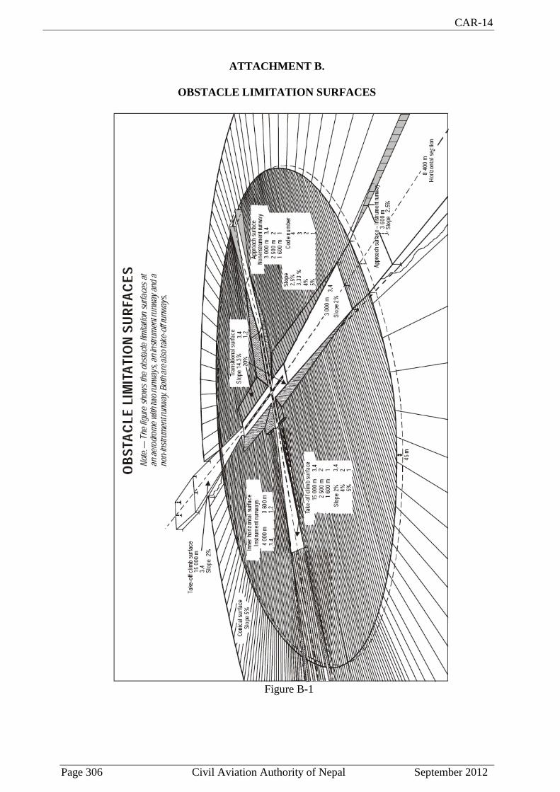
CAR-14
Page 306 Civil Aviation Authority of Nepal September 2012
ATTACHMENT B.
OBSTACLE LIMITATION SURFACES
Figure B-1
CAR-14
Page 307 Civil Aviation Authority of Nepal September 2012
ATTACHMENT C.
FRAMEWORK FOR THE STATE SAFETY PROGRAMME (SSP)
This attachment introduces a framework for the implementation and maintenance of a State safety programme (SSP) by a State. An SSP is a management system for the management of safety by the State. The framework contemplates four components and eleven elements, outlined hereunder. The implementation of an SSP is commensurate with the size and complexity of the State's aviation system, and may require coordination among multiple authorities responsible for individual elements of civil aviation functions in the State. The SSP framework introduced in this attachment, and the safety management system (SMS) framework specified in Appendix 7, must be viewed as complementary, yet distinct, frameworks. This attachment also includes a brief description of each element of the framework.
1. State safety policy and objectives
1.1 State safety legislative framework 1.2 State safety responsibilities and accountabilities 1.3 Accident and incident investigation 1.4 Enforcement policy
2. State safety risk management
2.1 Safety requirements for the service provider's SMS
2.2 Agreement on the service provider's safety performance
3. State safety assurance
3.1 Safety oversight
3.2 Safety data collection, analysis and exchange
3.3 Safety-data-driven targeting of oversight of areas of greater concern or need
4. State safety promotion
4.1 Internal training, communication and dissemination of safety information
4.2 External training, communication and dissemination of safety information
Note.— Within the context of this attachment the term " service provider" refers to any organization providing aviation services. The term includes approved training organizations that are exposed to safety risks during the provision of their services, aircraft operators, approved maintenance organizations, organizations responsible for type design and/or manufacture of aircraft, air traffic services providers and certified aerodromes, as applicable.
1. State safety policy and objectives
1.1 State safety legislative framework
The State has promulgated a national safety legislative framework and specific regulations, in
compliance with international and national standards, that define how the State will conduct the
management of safety in the State. This includes the participation of State aviation organizations
CAR-14
Page 308 Civil Aviation Authority of Nepal September 2012
in specific activities related to the management of safety in the State, and the establishment of the
roles, responsibilities and relationships of such organizations. The safety legislative framework
and specific regulations are periodically reviewed to ensure they remain relevant and appropriate to
the State.
1.2 State safety responsibilities and accountabilities
The State has identified, defined and documented the requirements, responsibilities and
accountabilities regarding the establishment and maintenance of the SSP. This includes the
directives to plan, organize, develop, maintain, control and continuously improve the SSP in a
manner that meets the State's safety objectives. It also includes a clear statement about the provision
of the necessary resources for the implementation of the SSP.
1.3 Accident and incident investigation
The State has established an independent accident and incident investigation process, the sole
objective of which is the prevention of accidents and incidents, and not the apportioning of blame
or liability. Such investigations are in support of the management of safety in the State. In the
operation of the SSP, the State maintains the independence of the accident and incident
investigation organization from other State aviation organizations.
1.4 Enforcement policy
The State has promulgated an enforcement policy that establishes the conditions and
circumstances under which service providers are allowed to deal with, and resolve, events
involving certain safety deviations, internally, within the context of the service provider's safety
management system (SMS), and to the satisfaction of the appropriate State authority. The
enforcement policy also establishes the conditions and circumstances under which to deal with
safety deviations through established enforcement procedures.
2. State safety risk management
2.1 Safety requirements for the service provider's SMS
The State has established the controls which govern how service providers will identify hazards and
manage safety risks. These include the requirements, specific operating regulations and
implementation policies for the service provider's SMS. The requirements, specific operating
regulations and implementation policies are periodically reviewed to ensure they remain relevant
and appropriate to the service providers.
2.2 Agreement on the service provider's safety performance
The State has agreed with individual service providers on the safety performance of their SMS. The
agreed safety performance of an individual service provider's SMS is periodically reviewed to
ensure it remains relevant and appropriate to the service providers.

CAR-14
Page 309 Civil Aviation Authority of Nepal September 2012
3. State safety assurance
3.1 Safety oversight
The State has established mechanisms to ensure effective monitoring of the eight critical
elements of the safety oversight function. The State has also established mechanisms to ensure
that the identification of hazards and the management of safety risks by service providers
follow established regulatory controls (requirements, specific operating regulations and
implementation policies). These mechanisms include inspections, audits and surveys to ensure
that regulatory safety risk controls are appropriately integrated into the service provider's SMS,
that they are being practised as designed, and that the regulatory controls have the intended
effect on safety risks.
3.2 Safety data collection, analysis and exchange
The State has established mechanisms to ensure the capture and storage of data on hazards and
safety risks at both an individual and aggregate State level. The State has also established
mechanisms to develop information from the stored data, and to actively exchange safety
information with service providers and/or other States as appropriate.
3.3 Safety-data-driven targeting of oversight of areas of greater concern or need
The State has established procedures to prioritize inspections, audits and surveys towards those
areas of greater safety concern or need, as identified by the analysis of data on hazards, their
consequences in operations, and the assessed safety risks.
4. State safety promotion
4.1 Internal training, communication and dissemination of safety information
The State provides training and fosters awareness and two-way communication of safety-
relevant information to support, within the State aviation organizations, the development of an
organizational culture that fosters an effective and efficient SSP.
4.2 External training, communication and dissemination of safety information
The State provides education and promotes awareness of safety risks and two-way
communication of safety-relevant information to support, among service providers, the
development of an organizational culture that fosters an effective and efficient SMS.
__________________________________________