Civil & Environmental Engineering - OMICS Publishing Group
8
Volume 2 • Issue 1 • 1000107 J Civil Environment Engg ISSN: 2165-784X JCEE, an open access journal Civil & Environmental Engineering Alam and Ansell, J Civil Environment Engg 2012, 2:1 http://dx.doi.org/10.4172/2165-784X.1000107 Research Article Open Access Short Term Lateral Shear Loading of Nailed Spruce-Steel-Spruce Flitch Joints and the Modification of Eurocode 5 Predictions for Design Resistance Parvez Alam 1 * and Martin P Ansell 2 1 Centre for Functional Materials, Abo Akademi University, Finaland 2 Department of Mechanical Engineering, University of Bath, United Kingdom Abstract In this paper, spruce-steel-spruce flitch joints connected by shot fired nails are subjected to short term loads. The failure modes and design resistance equations are compared with those detailed in Eurocode 5. The formation of a plastic hinge is observed in the nails at the steel-timber interface and Mode I (tensile opening) occurs longitudinally along the grain following the row of nails. The predictive equations of force in Eurocode 5 for dowel-type joints are modified with respect to yield moment and unequal fastener penetration depths to produce a significantly improved predictive equation for force. *Corresponding author: Parvez Alam, Centre for Functional Materials, Abo Akademi University, Finland, Tel: +35822154858; E-mail: parvez.alam@abo.fi Received December 25, 2011; Accepted January 19, 2012; Published January 21, 2012 Citation: Alam P, Ansell MP (2012) Short Term Lateral Shear Loading of Nailed Spruce-Steel-Spruce Flitch Joints and the Modification of Eurocode 5 Predictions for Design Resistance. J Civil Environment Engg 2:107. doi:10.4172/2165-784X.1000107 Copyright: © 2012 Alam P, et al. This is an open-access article distributed under the terms of the Creative Commons Attribution License, which permits unrestricted use, distribution, and reproduction in any medium, provided the original author and source are credited. Keywords: Spruce flitch joints; Load carrying capacity; Steel-spruce interface; Eurocode 5 Predictions; Timber joints Introduction Flitch joints are ubiquitous in timber constructions. e overall performance of such joints relies on the applicability and durability of mechanical fastenings. Shot fired nailing is a means by which the arduous task of drilling and bolting conventional flitch beams can be avoided. is technique exploits high strength steel nails, which are shot fired through both steel and timber members using an explosively charged nailing gun. It is of paramount importance that the capabilities and failure mechanisms of such fasteners are correctly understood if they are to be used in construction for both reinforced flitch beams and composite flitch joints. Mechanical fasteners are typically defined by the characteristics of force transfer between the connected members and the fasteners. Eurocode 5 specifications for predicting the design resistance of joints connected by dowel-type-fasteners are based upon models developed by [1]. Johansen’s [1] models are based on the embedment strength, f h , of the fastener in timber. In his models, the embedment strength was defined as p/dt where d is the diameter of the fastener, t is either the thickness of the timber member (assuming full fastener penetration) or the length of the fastener in the timber and p is the maximum load exerted upon the fastener. Johansen [1] reported a plastic yield plateau beyond a proportional limit below which linear elastic behavior dominates. Typically, f h is independent of the fastener diameter parallel to the grain [2] however, perpendicular to the grain f h decreases as a function of an increasing fastener diameter. According to Hilson [3], the embedment strength of nailed joints remains unaffected by loading at any angle relative to the timber grain. is is a possible consequence of the nail slenderness as compared with bolts and dowels. Additionally, Racher [4] postulates that the load carrying capacity, and therefore also f h , is independent of loading angle relative to the grain for any fasteners with a diameter below 8mm. e embedment strength however, both parallel and perpendicular to the grain increases as a function of increasing timber density [2]. Fasteners are also susceptible to plastic strains and fracture. Johansen’s models account for a maximum elastic moment capacity of fasteners. e potential increase in the moment that may occur when yielding proceeds in a fastener is however, unaccounted for. It is hypothesized in BS EN 409 (1993) [5] that plastic straining is reached across the whole cross section of a fastener at an angle of 45º and the yield moment capacities have thereby been incorporated into the EC5 modified Johansen models. e hypothesis of BS EN 409 (1993) has nevertheless been refuted in [6] where it was observed that an angle lower than 45º at peak failure load in many of their experiments. is showed that a plastic moment capacity could in fact be deemed specific to the yield angle of the fastener in question. To assume a yield angle of 45º is an over simplification that may give rise to inaccurate theoretical predictions. Multiple fastener joints commonly carry lower loads than the summation of the individual fastener capacities [7]. e same trend holds for the stiffness [8]. ese lower values can be attributed to factors such as the fastener slenderness ratio (fastener diameter: timber thickness), the fastener strength, the spacing distances used and the fabrication tolerances [9]. e lateral strength of fastened joints is arguably linked more so to fastener diameter than to fastener yield strength [10]. ey proved this through a comparative study of hammer and power driven nails, which are inherently different in strength properties as a consequence of their application method (power driven nails having higher strengths). e decrease in load carrying capacity as fastener number is increased is less marked as the timber members become thinner, i.e. as the slenderness ratio increases [11]. In fact, a 28% and 0% reduction in the load carrying capacity for joints with multiple fasteners relative to single fastener joints for slenderness ratios of 3 and 6 respectively has been reported [12]. eir test set up consisted of two rows of fasteners, each row containing three fasteners. Nevertheless, high load carrying capacities are possible with multiple fastened joints provided there is no premature brittle failure, such as timber splitting [13]. Increasing the number of fasteners in a row evolves a failure transition from ductile to brittle [14]. Brittle failure can be avoided by increasing the slenderness ratio. is was
Transcript of Civil & Environmental Engineering - OMICS Publishing Group

Volume 2 • Issue 1 • 1000107J Civil Environment EnggISSN: 2165-784X JCEE, an open access journal
Civil & Environmental EngineeringAlam and Ansell, J Civil Environment Engg 2012, 2:1
http://dx.doi.org/10.4172/2165-784X.1000107
Research Article Open Access
Short Term Lateral Shear Loading of Nailed Spruce-Steel-Spruce Flitch Joints and the Modification of Eurocode 5 Predictions for Design ResistanceParvez Alam1* and Martin P Ansell2
1Centre for Functional Materials, Abo Akademi University, Finaland2Department of Mechanical Engineering, University of Bath, United Kingdom
AbstractIn this paper, spruce-steel-spruce flitch joints connected by shot fired nails are subjected to short term loads. The
failure modes and design resistance equations are compared with those detailed in Eurocode 5. The formation of a plastic hinge is observed in the nails at the steel-timber interface and Mode I (tensile opening) occurs longitudinally along the grain following the row of nails. The predictive equations of force in Eurocode 5 for dowel-type joints are modified with respect to yield moment and unequal fastener penetration depths to produce a significantly improved predictive equation for force.
*Corresponding author: Parvez Alam, Centre for Functional Materials, Abo Akademi University, Finland, Tel: +35822154858; E-mail: [email protected]
Received December 25, 2011; Accepted January 19, 2012; Published January 21, 2012
Citation: Alam P, Ansell MP (2012) Short Term Lateral Shear Loading of Nailed Spruce-Steel-Spruce Flitch Joints and the Modification of Eurocode 5 Predictions for Design Resistance. J Civil Environment Engg 2:107. doi:10.4172/2165-784X.1000107
Copyright: © 2012 Alam P, et al. This is an open-access article distributed under the terms of the Creative Commons Attribution License, which permits unrestricted use, distribution, and reproduction in any medium, provided the original author and source are credited.
Keywords: Spruce flitch joints; Load carrying capacity; Steel-spruce interface; Eurocode 5 Predictions; Timber joints
IntroductionFlitch joints are ubiquitous in timber constructions. The overall
performance of such joints relies on the applicability and durability of mechanical fastenings. Shot fired nailing is a means by which the arduous task of drilling and bolting conventional flitch beams can be avoided. This technique exploits high strength steel nails, which are shot fired through both steel and timber members using an explosively charged nailing gun. It is of paramount importance that the capabilities and failure mechanisms of such fasteners are correctly understood if they are to be used in construction for both reinforced flitch beams and composite flitch joints.
Mechanical fasteners are typically defined by the characteristics of force transfer between the connected members and the fasteners. Eurocode 5 specifications for predicting the design resistance of joints connected by dowel-type-fasteners are based upon models developed by [1]. Johansen’s [1] models are based on the embedment strength, fh, of the fastener in timber. In his models, the embedment strength was defined as p/dt where d is the diameter of the fastener, t is either the thickness of the timber member (assuming full fastener penetration) or the length of the fastener in the timber and p is the maximum load exerted upon the fastener. Johansen [1] reported a plastic yield plateau beyond a proportional limit below which linear elastic behavior dominates. Typically, fh is independent of the fastener diameter parallel to the grain [2] however, perpendicular to the grain fh decreases as a function of an increasing fastener diameter. According to Hilson [3], the embedment strength of nailed joints remains unaffected by loading at any angle relative to the timber grain. This is a possible consequence of the nail slenderness as compared with bolts and dowels. Additionally, Racher [4] postulates that the load carrying capacity, and therefore also fh, is independent of loading angle relative to the grain for any fasteners with a diameter below 8mm. The embedment strength however, both parallel and perpendicular to the grain increases as a function of increasing timber density [2].
Fasteners are also susceptible to plastic strains and fracture. Johansen’s models account for a maximum elastic moment capacity of fasteners. The potential increase in the moment that may occur when yielding proceeds in a fastener is however, unaccounted for. It is hypothesized in BS EN 409 (1993) [5] that plastic straining is reached across the whole cross section of a fastener at an angle of 45º and the
yield moment capacities have thereby been incorporated into the EC5 modified Johansen models. The hypothesis of BS EN 409 (1993) has nevertheless been refuted in [6] where it was observed that an angle lower than 45º at peak failure load in many of their experiments. This showed that a plastic moment capacity could in fact be deemed specific to the yield angle of the fastener in question. To assume a yield angle of 45º is an over simplification that may give rise to inaccurate theoretical predictions.
Multiple fastener joints commonly carry lower loads than the summation of the individual fastener capacities [7]. The same trend holds for the stiffness [8]. These lower values can be attributed to factors such as the fastener slenderness ratio (fastener diameter: timber thickness), the fastener strength, the spacing distances used and the fabrication tolerances [9]. The lateral strength of fastened joints is arguably linked more so to fastener diameter than to fastener yield strength [10]. They proved this through a comparative study of hammer and power driven nails, which are inherently different in strength properties as a consequence of their application method (power driven nails having higher strengths). The decrease in load carrying capacity as fastener number is increased is less marked as the timber members become thinner, i.e. as the slenderness ratio increases [11]. In fact, a 28% and 0% reduction in the load carrying capacity for joints with multiple fasteners relative to single fastener joints for slenderness ratios of 3 and 6 respectively has been reported [12]. Their test set up consisted of two rows of fasteners, each row containing three fasteners.
Nevertheless, high load carrying capacities are possible with multiple fastened joints provided there is no premature brittle failure, such as timber splitting [13]. Increasing the number of fasteners in a row evolves a failure transition from ductile to brittle [14]. Brittle failure can be avoided by increasing the slenderness ratio. This was

Volume 2 • Issue 1 • 1000107J Civil Environment EnggISSN: 2165-784X JCEE, an open access journal
Citation: Alam P, Ansell MP (2012) Short Term Lateral Shear Loading of Nailed Spruce-Steel-Spruce Flitch Joints and the Modification of Eurocode 5 Predictions for Design Resistance. J Civil Environment Engg 2:107. doi:10.4172/2165-784X.1000107
Page 2 of 8
demonstrated in [9] where it was shown that joint ductility increased as the slenderness ratios were raised, while [15] have moreover encouraged the use of higher slenderness ratios in order to improve the ductile characteristics of joints. A justification however, for using rigid (hence low slenderness) fasteners, is that they increase the level of composite action in a joint that may otherwise be reduced through ductile slip [16]. This may be fine so long as the composite is loaded to well within its load bearing capabilities. At the load bearing limits however, rigid fasteners give rise to shear failure in the timber along the row of fasteners [17]. They furthermore reported on the importance of spacing distances between rows of fasteners. Such spacing distances determine whether the timber failure mode comprises a group tear out or a shear failure along the row of fasteners. A comparison of plastic failure modes for single fasteners against a row of five [18], demonstrated that by increasing the number of fasteners in a row, a significant decrease in plastic deformation within the fasteners was possible. A ductile to brittle failure transition is moreover an outcome of increasing the number of fasteners in a row from the loaded edge [19]. According to [20] smaller distances between fasteners reduce the load carrying capabilities and furthermore, [21] stipulate that failure takes place much faster as a function of reduced spacing distances. Edge distances also influence the failure mode and the load bearing capabilities and fasteners farther from the loaded edge carry higher loads [22].
The aim of this communication is to assess the performance and behavior of high strength steel nails in a timber-steel-timber joint where the nails are subjected to lateral double shear. The predictive force equations for dowel type joints in Eurocode 5 will furthermore be assessed as regards validity of application to these shot fired nailed flitch systems.
ProcedureComposite flitch joints were manufactured by sandwiching two
mild steel plates at a distance of 20mm between two sections of Sitka spruce (Picea sitchensis), Figure 1. The steel and spruce were connected by shooting 80mm long, high strength steel nails, Figure 2(a), through the 3-layer system in a single shot action using a SPIT200 nailing gun, Figure 2(b). No pre-drilling was necessary as the explosive charge, Figure 2(c), generated sufficient force to drive the nails through both the steel plate and the spruce. All nails were embedded from the same side of the composite and all nail heads therefore lay in one of the spruce sections, see side view in Figure 1. The nails may, to some extent, countersink into the timber due to the force of the explosion. The depth of nail head penetration into the spruce was variable and highly dependent upon the force of thrust relative to the resistance in the steel and timber members beneath the incoming nail. It could be noted that the shank of the nail does not penetrate the full depth of both timber sections. The timber thickness on both sides of the joint can therefore be considered as equal to the depth of point side and head side penetration depths of the nail.
From observation it was evident that the nail tip did not deform after penetrating the steel. The nails were fired in through the same side of the specimen. The dimensions of the composite elements and fasteners are given in Table 1. The high strength of the steel nails is achievable through the lower bainite reaction, which facilitates the production of carbon in large quantities and effectively strengthens the steel.
Four nails were used to connect each plate between the sections of spruce. The nail spacing arrangement parallel to the grain (a1), perpendicular to the grain (a2) and from the loaded edge (a3,t) were
respectively 12, 40 and 14 times the diameter of the nail, d, which was 3.6mm. The spacing arrangement for the nails perpendicular to the grain is eight times higher than the guidance for minimum spacing distance given in Eurocode 5 (EC5), (DD ENV1995-1-1 (1994)) [23] and four times higher than the guidance for minimum spacing distance as stipulated in BS 5268-2 (2002) [24]. This alleviates the potential interaction of localized stresses between the nails in the wood perpendicular to the grain. Hence, the burden imposed upon the spruce timber should theoretically be confined to the direction parallel to the grain. Table 2 details the nail spacing arrangement employed for the test specimens. Also in Table 2 is the guidance provided for relevant minimum nail spacing distances according to both EC5 and BS 5268 Part 2 (2002).
The moisture content was determined for the spruce timber by oven drying and was found to be approximately 12%. In total, ten composite double shear flitch joints were tested in service class 2 conditions. Each shear joint was subjected to tensile loading until slightly beyond the peak load. Load was applied via pre-drilled holes in the steel plates, Figure 1, which consequently transferred the load through the nails and into the spruce. The nails were therefore subjected to lateral shear. A slow crosshead speed of 1mm.min-1 was used to reduce the chances of premature brittle failure in either the nails or the timber. Two linear variable differential transformer (LVDT) displacement transducers were attached to the plates at each end of each flitch joint.
Figure 1: Plan and side view of double shear test set up showing dimensions of composite members, nail spacing distances, position of LVDT displacement transducers and direction of force application.
Material Length/mm
Width/mm
Thickness/mm
Diameter/mm
No. used per specimen
Mild steel 200 180 6 - 2Sitka spruce(C16) 260 190 47 - 2Nails 80 - - 3.6 8
Table 1: Dimensional properties of composite elements making up the spruce-steel flitch joints.

Volume 2 • Issue 1 • 1000107J Civil Environment EnggISSN: 2165-784X JCEE, an open access journal
Citation: Alam P, Ansell MP (2012) Short Term Lateral Shear Loading of Nailed Spruce-Steel-Spruce Flitch Joints and the Modification of Eurocode 5 Predictions for Design Resistance. J Civil Environment Engg 2:107. doi:10.4172/2165-784X.1000107
Page 3 of 8
that the pointside angles should be higher than the headside angles because the deformation on the headside of the shank is restrained axially by the presence of a nail head whereas in contrast, the nail tip does not cause any degree of restraint. It is also worth noting that these angles, which were post-yield angles, are significantly lower than the yield angle for calculation of a yield moment as suggested in BS EN 409 (1993) because the bainitically hardened nails are essentially hard and brittle. This standard describes the yield moment as being the bending moment at peak load for a nail, or the load at which a fastener bends through an angle of 45º, whichever is the lesser. Bla et al. [6] have also noted that many fasteners yield at a lower angle than 45º and acknowledged that such an oversimplification could lead to inaccurate theoretical determination of the load carrying capabilities. Therefore, the peak load value, rather than the load at an angle of 45º, was used to determine the yield moment and calculations were carried out according to BS EN 409 [5]. In this test an 80mm long nail was subjected to four point bending. The span of the bottom rollers was 65mm and the distance between the top rollers, l2, was 32mm, Figure 6. The distance between the applied load and the nearest support, l1 and l3, was equal on both sides and was equal to 16.5mm.
The yield and peak stresses were observed to be 2.69GPa and 3.56GPa respectively. As the yield angle of the fastener is below 45º, the load at such an angle cannot be determined. The other alternative advised by BS EN 409 [5] is to use the lesser of the product of either F1l1 or F3l3, where F is the maximum force. In this test F1l1 = F3l3 and the yield moment, My, is calculated as 16558Nmm.
Modification of the current Eurocode 5 equations
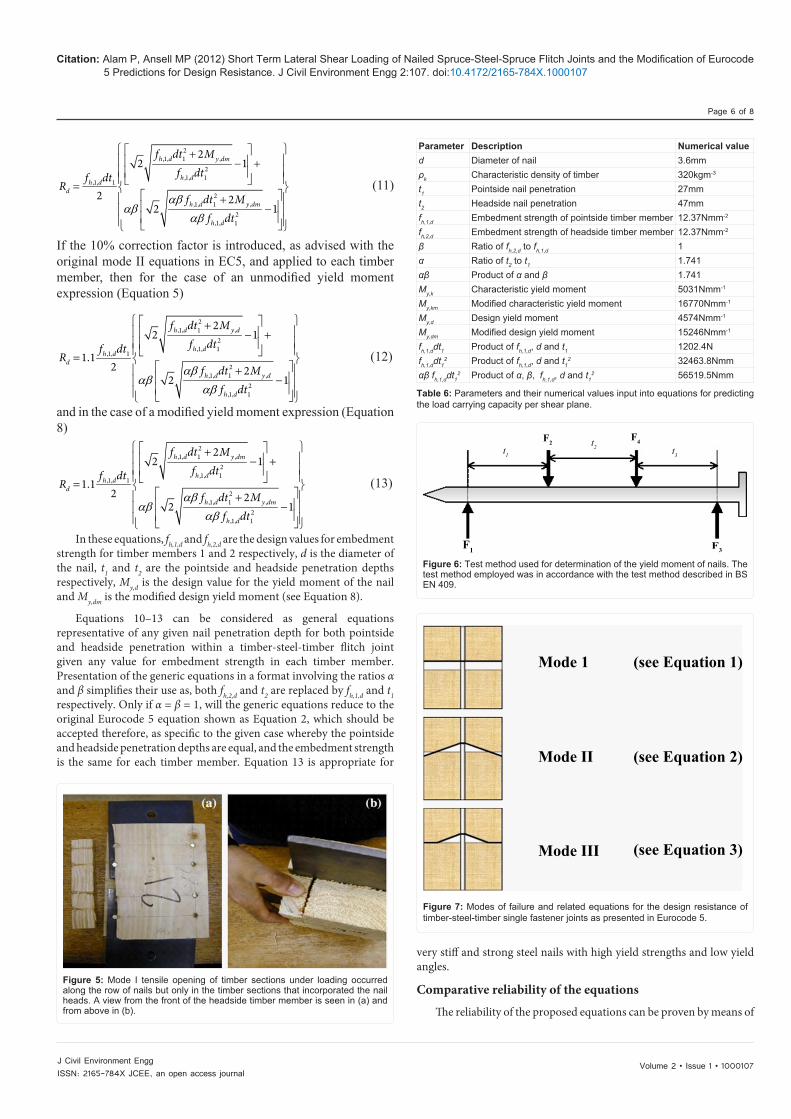
EC5 predictions for the design resistance, Rd, for single fastener connected timber-steel-timber joints are illustrated in Figure 7 and represented by Equations 1 to 3 (modified Johansen equations).
= ,1, 11.1d h dR f t d (1)
= + −
,,1, 1 2
,1, 1
41.1 2 1y d
d h dh d
MR f dt
f dt (2)
= , ,1,1.5 2d y d h dR M f d (3)
When applied to nailed joints, t1 is taken as the lower value of headside or pointside penetration, d is the diameter of the nail, fh,1,d is the design value for the embedment strength of the nail into one of the timber members and My,d is the design value for the yield moment of the nail. The design value for embedment, f,h,1,d is represented by Equation 4.
γ= mod ,1,
,1,( )
h kh d
m timber
k ff (4)
The monitoring head of each LVDT displacement transducer was positioned to rest upon each end of the spruce section. The LVDT displacement transducers were located in line with each other with the spring-loaded probes resting upon the spruce section in the grain direction on the side of nail head penetration. The LVDT displacement transducers were used to measure the magnitude of slip between the plates and the spruce sections during testing.
Lateral load carrying capacity of the fasteners
The average load carrying capacity of the joint that is, for four nails, was 20.45kN with a standard deviation of ±2.34kN. Taking the assumption of a uniform distribution of load between each nail; the mean load carrying capacity per shear plane amounts to 2.56kN with a standard deviation of ±0.29kN about the mean. Table 3 compares the load carrying capacity per shear plane with the similar dimension round wire nails in steel-timber joints (strength class C16) as described in Table 2 of BS 5268-2 (2002). The values in Table 3 for BS 5268-2 (2002) are for timber-timber joints and are used for steel-timber joints with a correction factor of 1.25.
Figure 3 shows the load-slip behavior of the samples with the highest and lowest values for loading resistance. For reasons of clarity, the plots for every specimen are not plotted. Steel plate slip from the spruce sections is measured using the LVDT displacement transducers, and is plotted for both ends of each sample. Slip was measured on the same side of each end of each sample (refer to Figure 1).
Failure observations
The load-slip characteristic of the nails all followed a trend whereby the nails developed a plastic hinge at the interfacial region between the steel plate and the timber. Subsequent plastic deformation in the spruce ensued as the nail embedded into the spruce members, which thereby initiated the onset of cracking in the spruce, Figure 4.
Mode I failure (tensile opening) was observed occurring longitudinally along the grain following the row of nails. This failure only happened in the timber section containing the nail heads. This is believed to be because the nails heads create localized stress concentrations in the wood parallel to the grain axis. Some of the nails also failed catastrophically, however the majority only experienced plastic deformation. Figure 5 shows mode I timber failure as viewed from the front (a) and from above (b).
Nail angle and yield moment
Loading was stopped for three of the ten flitch joints immediately after composite failure. Both pointside and headside deformed fastener angles were checked in these three specimens. On average, the pointside angle was 9.2º and the headside angle was 8.1º. It is logical
(d-diameter of nail )
Nail spacing distances in mmParallel to the grain (a)
Perpendicularto the grain (a2)
From the loaded edge (a3,t)
Test specimens (spruce-steel flitch) 12d 40d 14dEurocode 5 (DD ENV 1995-1-1) for nailing without pre-drilled holes. ( The same guidance is advised for steel timber jointsas is for the timber-timber joints)
10d 5d 15d
BS 5268 part 2 (2002) for nailing timberWithout pre-drilled holes 20d 10d 20d
BS 5268 part 2 (2002) for nails in steel-timberJoints with pre-drilled holes 14d 7d 14d
Table 2: Nail spacing arrangement for test specimens and minimum nail spacing arrangement according to guidance in Eurocode 5 (DD ENV 1995-1-1) [23] and BS 5268-2 (2002) [24].

Volume 2 • Issue 1 • 1000107J Civil Environment EnggISSN: 2165-784X JCEE, an open access journal
Citation: Alam P, Ansell MP (2012) Short Term Lateral Shear Loading of Nailed Spruce-Steel-Spruce Flitch Joints and the Modification of Eurocode 5 Predictions for Design Resistance. J Civil Environment Engg 2:107. doi:10.4172/2165-784X.1000107
Page 4 of 8
In Equation 4, fh,1,k is defined as the characteristic embedment strength of the nail into one of the timber members and is calculated as 0.082ρkd
-0.3Nmm-2 (ρk is the density of the timber member into which
embedment occurs in kgm-3 and d is the nail diameter and is input into the equation in mm). The modification factor, kmod is for solid timber under service class 2 conditions and short-term loading and is 0.9 as instructed in the EC5. γm(timber) is a partial coefficient for materials properties of solid timber and is advised as being 1.3. The design yield moment, My,d, is represented by Equation 5.
γ= ,
,( )
y ky d
m steel
MM (5)
In Equation 5 the characteristic yield moment, My,k, is relevant to common smooth steel wire nails with a minimum tensile strength of 600MPa and is calculated according to Equation 6. γm(steel) is the partial coefficient for materials properties of steel and is advised as being 1.1.
= 2.6, 180y kM d (6)
EC5 recommends the use of the lowest value for the design resistance, regardless of the failure mode that arises. The limitations of the EC5 approach are immediately obvious. The predicted Rd may be much lower than an empirically determined Rd. The reasons can be summarized as follows:
o My,k is calculated on the basis that the tensile strength of the nails is 600MPa. For higher or lower strength fasteners, the characteristic yield moment is likely to be different, and indeed, related to the yield strength properties of the fastener. With regards to the current nails being used, the tensile strength is approximately 2GPa, and therefore My,k is likely to be higher than is calculated using the current EC5 equation.
o EC5 describes t1 as being the lesser of the headside or pointside penetrations. Therefore, if there exists a significantly higher penetration in one timber member relative to the other, as was clearly observed in the tests conducted, the lower t1 is likely to give a very pessimistic design resistance often not observed in practice, especially for very hard grades of steel. The average pointside penetration to the nearest integer was recorded as 27mm, which was almost half the penetration depth in the headside timber member (47mm to the nearest integer).
Modification of the predicted yield moment
For the reasons described above, it seems plausible to suggest the use of a modified equation that accounts for different yield moments that may arise in fasteners with different strengths as well as accounting for both pointside and headside penetration depths. As higher strength fasteners yield at a lower angle than the value of 45o specified by BS EN 409 [5], the yield moment is calculated from the flexural strength. If a linear relationship is assumed between the flexural strength, σf, and
Figure 2: (a) An example of the high strength steel nails used in the flitch joint tests, (b) the nailing gun and (c) the nails are fired through the composite by means of a forceful explosion delivered by these charges.
25
20
15
10
5
00 2 4 6 8 10
S7 -slip at top S7 -slip at bottom
S9 -slip at bottompeak lod arithmetic mean for sample set
S9 - slip at top
Slip of plate from wood/mm
Load
/KN
Figure 3: Load-slip characteristics of spruce-steel composite joints. The slip, measured using an LVDT displacement transducer, is plotted for both ends of each sample. For reasons of clarity, the load-slip characteristic is plotted for only the joints showing the highest and lowest load carrying capacities.
Figure 4: Typical failure mode comprising plastic failure of timber under the deforming nail. The nail forms a plastic hinge at the steel plate to timber interface. In this picture however, the nail has fractured after yielding.
Nail diameter/mm
Average penetration depth/mm
Load carrying capacity /N
Tested nails 3.6 37 2560BS 5268 (2002) 3.4 41 471BS 5268 (2002) 3.8 46 566
Table 3: Comparison of load carrying capacity per shear plane of different nails in a flitch joint.
Table 4: Comparison of EC5 characteristic yield moment expression and modified characteristic yield moment expression with experimentally determined yield moment.
Yield moment expression Yield moment value/Nmm-1
Calculated yield moment, My 16558EC5 My,k 5031Modified expression (Equation 7), My,km 16770

Volume 2 • Issue 1 • 1000107J Civil Environment EnggISSN: 2165-784X JCEE, an open access journal
Citation: Alam P, Ansell MP (2012) Short Term Lateral Shear Loading of Nailed Spruce-Steel-Spruce Flitch Joints and the Modification of Eurocode 5 Predictions for Design Resistance. J Civil Environment Engg 2:107. doi:10.4172/2165-784X.1000107
Page 5 of 8
the tensile strength, σt, then Equation 6 can be factored by a ratio of σt to σ600, where σ600 represents a tensile strength of 600MPa to give a modified characteristic yield moment equation, Equation 7, which shall be denoted as My,km.
σσ
= 2.6
,600
180ty kmM d (7)
The design yield moment is therefore modified from Equation 5 to give Equation 8.
γ= ,
,( )
y kmy dm
m steel
MM (8)
Equation 8 can replace My,d in Equations 2 and 3. Table 4 compares the experimentally determined yield moment, My, with the EC5 predictions, My,k, and the modified predictions, My,km, from Equation 7, for σt = 2GPa .
Table 4 demonstrates that the characteristic yield moment, My,km, from Equation 7, is much closer to the experimentally determined yield moment, which was calculated according to BS EN 409 (1993).
Modification for unequal fastener penetration depthsThe tested spruce-steel composite joints failed according to the
mode II mechanism in Figure 7, which corresponds to Equation 2 (EC5). As mentioned before, the headside penetration depth is approximately one and a half times greater than the pointside penetration depth. The next modification to the EC5 equation accounts for both penetration depths as well as the possible different embedment strengths of two dissimilar timber members. Figure 8 is an illustration of a nail in a timber-steel-timber joint where the headside and pointside penetration depths are unequal. The pointside penetration depth in this diagram is taken as t1 and the headside penetration depth is taken as t2. A more accurate representation of the Equation 2 would average the load carrying capacities of both sides of the joint. This can be represented by Equation 9.
= + − + + −
, ,,1, 1 ,2, 22 2
,1, 1 ,2, 2
4 41 2 1 2 12
y d y dd h d h d
h d h d
M MR f dt f dt
f dt f dt (9)
By taking the common denominator, 2,1, 1h df dt ,
+ −,2
,1, 1
42 1y d
h d
Mf dt
can be expressed as
+−
2,1, 1 ,
2,1, 1
2 41h d y d
h d
f dt Mf dt
, which can be simplified to
+−
2,1, 1 ,
2,1, 1
22 1h d y d
h d
f dt Mf dt
.
Using a similar approach, + −,2
,2, 2
42 1y d
h d
Mf dt
can be expressed as
+−
2,2, 2 ,
2,2, 2
22 1h d y d
h d
f dt Mf dt
by taking 2,2, 2h df dt as the common
denominator.
This yields an equation, which can be represented as
+ − + =
+ −
2,1, 1 ,
,1, 1 2,1, 1
2,2, 2 ,
,2, 2 2,2, 2
22 1
12 2
2 1
h d y dh d
h d
d
h d y dh d
h d
f dt Mf dt
f dtR
f dt Mf dt
f dt
If β=,2,
,1,
h d
h d
ff
, and α=2
1
tt
, then
αβαβ
αβ
+ − + =
+ −
2,1, 1 ,
,1, 1 2,1, 1
2,1, 1 ,
,1, 1 2,1, 1
22 1
12 2
2 1
h d y dh d
h d
d
h d y dh d
h d
f dt Mf dt
f dtR
f dt Mf dt
f dt
,
which allows fh,1,d, t1 and d to be taken out, giving
αβαβ
αβ
+ − + =
+ −
2,1, 1 ,
2,1, 1
,1, 1
2,1, 1 ,
2,1, 1
22 1
2 22 1
h d y d
h dh d
d
h d y d
h d
f dt Mf dtf dt
Rf dt M
f dt
(10)
If the modified design yields moment is applied, then
Designated title Description EquationLowest of 3 EC5 advice on taking the lowest design resistance value obtained from three equations (1-3) 1 to 3
Lowest of 3 (My,dm) EC5 advice on taking the lowest value obtained from three equations (1 to 3) except replacing the yield moment, My,d, with the modified yield moment, My,dm
-
Modified equation 10 Modified equation to account for headside and pointside penetration in potentially dissimilar timber members that may have different values for the embedment strength 10
Modified equation 11 (My,dm) Modified equation to account for headside and pointside penetration in potentially dissimilar timber members that may have different values for the embedment strength and replacing My,d with My,dm
11
Modified equation 12 (10%)Modified equation to account for headside and pointside penetration in potentially timber members that may have different values for the embedment strength. Includes the 10% correction factor recommended in the original EC5 equations
12
Modified equation 13 (10%) (My,dm)
Modified equation to account for headside and pointside penetration in potentially dissimilar timber members that may have different values for the embedment strength. Includes the 10% correction factor recommended in the original EC5 equations and replaces My,d with My,dm
13
Table 5: Designated titles given to the methods used for predicting the load carrying capacity per shear plane of timber-steel-timber joints with relevant Equation numbers provided.
Volume 2 • Issue 1 • 1000107J Civil Environment EnggISSN: 2165-784X JCEE, an open access journal
Citation: Alam P, Ansell MP (2012) Short Term Lateral Shear Loading of Nailed Spruce-Steel-Spruce Flitch Joints and the Modification of Eurocode 5 Predictions for Design Resistance. J Civil Environment Engg 2:107. doi:10.4172/2165-784X.1000107
Page 6 of 8
αβαβ
αβ
+ − + =
+ −
2,1, 1 ,
2,1, 1
,1, 1
2,1, 1 ,
2,1, 1
22 1
2 22 1
h d y dm
h dh d
d
h d y dm
h d
f dt Mf dtf dt
Rf dt M
f dt
(11)
If the 10% correction factor is introduced, as advised with the original mode II equations in EC5, and applied to each timber member, then for the case of an unmodified yield moment expression (Equation 5)
αβαβ
αβ
+ − + =
+ −
2,1, 1 ,
2,1, 1
,1, 1
2,1, 1 ,
2,1, 1
22 1
1.12 2
2 1
h d y d
h dh d
d
h d y d
h d
f dt Mf dtf dt
Rf dt M
f dt
(12)
and in the case of a modified yield moment expression (Equation 8)
αβαβ
αβ
+ − + =
+ −
2,1, 1 ,
2,1, 1
,1, 1
2,1, 1 ,
2,1, 1
22 1
1.12 2
2 1
h d y dm
h dh d
d
h d y dm
h d
f dt Mf dtf dt
Rf dt M
f dt
(13)
In these equations, fh,1,d and fh,2,d are the design values for embedment strength for timber members 1 and 2 respectively, d is the diameter of the nail, t1 and t2 are the pointside and headside penetration depths respectively, My,d is the design value for the yield moment of the nail and My,dm is the modified design yield moment (see Equation 8).
Equations 10–13 can be considered as general equations representative of any given nail penetration depth for both pointside and headside penetration within a timber-steel-timber flitch joint given any value for embedment strength in each timber member. Presentation of the generic equations in a format involving the ratios α and β simplifies their use as, both fh,2,d and t2 are replaced by fh,1,d and t1 respectively. Only if α = β = 1, will the generic equations reduce to the original Eurocode 5 equation shown as Equation 2, which should be accepted therefore, as specific to the given case whereby the pointside and headside penetration depths are equal, and the embedment strength is the same for each timber member. Equation 13 is appropriate for
very stiff and strong steel nails with high yield strengths and low yield angles.
Comparative reliability of the equations
The reliability of the proposed equations can be proven by means of
Parameter Description Numerical valued Diameter of nail 3.6mmρk Characteristic density of timber 320kgm-3
t1 Pointside nail penetration 27mmt2 Headside nail penetration 47mmfh,1,d Embedment strength of pointside timber member 12.37Nmm-2
fh,2,d Embedment strength of headside timber member 12.37Nmm-2
β Ratio of fh,2,d to fh,1,d 1α Ratio of t2 to t1 1.741αβ Product of α and β 1.741My,k Characteristic yield moment 5031Nmm-1
My,km Modified characteristic yield moment 16770Nmm-1
My,d Design yield moment 4574Nmm-1
My,dm Modified design yield moment 15246Nmm-1
fh,1,ddt1 Product of fh,1,d, d and t1 1202.4Nfh,1,ddt1
2 Product of fh,1,d, d and t12 32463.8Nmm
αβ fh,1,ddt12 Product of α, β, fh,1,d, d and t1
2 56519.5Nmm
Table 6: Parameters and their numerical values input into equations for predicting the load carrying capacity per shear plane.
t1
t2 t3
F2
F1 F3
F4
Figure 6: Test method used for determination of the yield moment of nails. The test method employed was in accordance with the test method described in BS EN 409.
Figure 5: Mode I tensile opening of timber sections under loading occurred along the row of nails but only in the timber sections that incorporated the nail heads. A view from the front of the headside timber member is seen in (a) and from above in (b).
Mode 1
Mode II
Mode III
(see Equation 1)
(see Equation 2)
(see Equation 3)
Figure 7: Modes of failure and related equations for the design resistance of timber-steel-timber single fastener joints as presented in Eurocode 5.

Volume 2 • Issue 1 • 1000107J Civil Environment EnggISSN: 2165-784X JCEE, an open access journal
Citation: Alam P, Ansell MP (2012) Short Term Lateral Shear Loading of Nailed Spruce-Steel-Spruce Flitch Joints and the Modification of Eurocode 5 Predictions for Design Resistance. J Civil Environment Engg 2:107. doi:10.4172/2165-784X.1000107
Page 7 of 8
penetration depths brings the predicted value closer to the true tested values. The combination of accounting for the different penetration depths of the nail, together with the implementation of the modified yield moment into the equations shows an improved prediction when increased by the EC5 advised 10%. The load carrying capacity as predicted by Equation 13 lies at the lower bound load carrying capacity of the test sample set.
For reasons of safety, design of timber structures incorporates strength values taken at the lower 5th percentile calculated from a sample set. Given that the sample size, n, is small (10 samples), it will have to be assumed that the data follows a normal distribution. The lower 5th percentile value for the load carrying capacity, Rd,0.05, can be calculated by defining the lower 5th percentile confidence interval using Equation 14.
= −
,9
,0.05 0.05,9X
d
SR X t
n (14)
n Sample size (= 10)
t0.05,9 t-value from table of t-values for a 90% confidence interval using an estimator of n-1 for the sample size (= 9)
SX,9 Estimated standard deviation for a small sample size where an unbiased estimate of n-1 is used for the sample set X and,
( )=
= −−∑
2
,91
11
n
X ii
S X Xn
(15)
X - Mean of the sample set
Therefore, Rd,0.05 = 2.39kN per shear plane and the closest prediction (from Equation 13) is 0.39kN lower than the 5th percentile characteristic strength. Moreover, a hypothesis claiming that the predicted Rd from Equation 13 is the sample mean can be rejected at every tabulated level of significance. More clearly,
µ
−
−= = > = > =0.005,9 0.1,9
, 1
6.45 3.25 1.383/
Xn
X n
XT t tS n
and the Equation 13 prediction lies outside a 99% confidence interval as well as an 80% confidence interval.
Tn Calculated T-test value
t0.005,9 t-value from table of t-values for a 99% confidence interval using an estimator of n-1for the sample size (= 9)
t0.1,9 t-value from table of t-values for a 80% confidence interval using an estimator of n-1for the sample size (= 9)
μX theoretical value of Rd from Equation 13
The modified yield moment assumes that there is a linear relationship between the flexural strength and yield strength of different strength fasteners. This approximation may well be slightly detrimental to the load carrying of the nails predicted in Equation 13. An empirical study to determine the true relationship between the flexural strength and yield strength of different strength fasteners will allow a more accurate modification of Equation 13.
ConclusionsDouble shear steel-spruce flitch joints connected by shot fired
nailing have been subjected to short term loading in service class 2 conditions. The load carrying capacity per shear plane for shot fired nailed flitch joints tested in double shear was calculated as 2.56kN with a standard deviation about the mean of ±0.29kN. This assumes an equal distribution of load between the eight nails used per joint. The
Nail
Steel plate
t1t2
Figure 8: Illustration of a nailed timber-steel-timber joint where the headside and pointside penetration depths are different. The pointside and headside penetration depths are denoted t1 and t2 respectively.
Load carrying capacity per sher plane/kn0 0.5 1 1.5 2 2.5 3
Figure 9: A comparison of different theoretical approaches towards predicting the load carrying capacity per shear plane of nailed timber-steel-timber joints.
direct comparison with the values obtained from the tested specimens for the load carrying capacity per shear plane. Table 5 describes the methods for predicting the load carrying capacity and the numerical values are compared in Figure 9. Experimental parameters are listed in Table 6 and these correspond to the high strength nails and the spruce timber used in the experiments.
Examination of Figure 9 shows that the load carrying capacity predicted by the modified equations is far more accurate than the current ‘Lowest of 3’ EC5 predictions. It is also clear that the ‘Lowest of 3’ EC5 predictions are far below the true carrying capacity of the tested nailed joints. Application of the modified yield moment in the equations tends to increase the load carrying capacity to a greater extent than simply accounting for the different penetration depths. Although [10] reported that the lateral strength of nailed joints depends less on the yield strength of the nail and more on the nail diameter, it is clear that the strength of the nail is highly influential upon the load carrying characteristics of nailed joints.
Nonetheless, it is also clear that accounting for the different

Volume 2 • Issue 1 • 1000107J Civil Environment EnggISSN: 2165-784X JCEE, an open access journal
Citation: Alam P, Ansell MP (2012) Short Term Lateral Shear Loading of Nailed Spruce-Steel-Spruce Flitch Joints and the Modification of Eurocode 5 Predictions for Design Resistance. J Civil Environment Engg 2:107. doi:10.4172/2165-784X.1000107
Page 8 of 8
joints exhibited ductile characteristics until failure, which was usually mode I (tensile opening) of the spruce along the line of nails. The nails developed a single plastic hinge at the steel-spruce interface (mode II fastener failure). The mean pointside failure angle was measured as 9.2o with the mean headside angle measured at 8.1o respectively in spruce-steel-spruce flitch joints connected by shot fired nails. The Eurocode 5 mode II equations for predicting the design resistance of timber-steel-timber joints fastened by mechanical fasteners was modified. The modified equations gave much closer predictions to the experimentally determined values than the Eurocode 5 predictions and are more suitable for use with high strength fasteners.
References
1. Johansen KW (1949) Theory of timber connections. International Association of Bridge and Structural Engineering 9: 249-262.
2. Sawata K, Yasumura M (2000) Evaluation of yield strength of bolted timber joints by Monte-Carlo simulation. Proceedings of the 6th World Conference on Timber Engineering (WCTE2000), British Columbia, Canada.
3. Hilson BO (1994) Design charts for nailed timber joints. Journal of the Institute of Wood Science 13: 459-461.
4. Racher P (1995) Mechanical timber joints – general. STEP/EUROFORTECH, Centrum Hout, The Netherlands.
5. BS EN 409 (1993) Timber structures – Test methods – Determination of the yield moment of dowel type fasteners – Nails. British Standards Institution, London.
6. Blass HJ, Bienhaus A, Krämer V (2000) Effective bending capacity of dowel-type fasteners. Proceedings Meeting 33, CIB W18, Delft, Netherlands.
7. Blass HJ (1995) Multiple fastener joints. STEP/EUROFORTECH, Centrum Hout, The Netherlands.
8. Jorissen A (1999) The stiffness of multiple bolt connections. Proceedings Meeting 32 CIB W18, Graz, Austria.
9. Mischler A, Gehri E (1999) Strength reduction rules for multiple fastener joints. Proceedings Meeting 32 CIB W18, Graz, Austria.
10. Chui YH, Chun N (2000) Performance of wood joints fastened with power driven nails. Proceedings of the 6th World Conference on Timber Engineering (WCTE2000), British Columbia, Canada.
11. Moss PJ (1998) Research into row modification factors for multiple-bolt
timber joints. Proceedings of the 5th World Conference on Timber Engineering (WCTE1998), Montreux, Switzerland, 2: 129-136.
12. Mischler A, Prion H, Lam F (2000) Load-carrying behaviour of steel-to-timber dowel connections. Proceedings of the 6th World Conference on Timber Engineering (WCTE2000), British Columbia, Canada.
13. Mischler A (1998) Doweled steel-to-timber joints with high efficiency. Proceedings of the 5th World Conference on Timber Engineering (WCTE1998), Montreux, Switzerland 1: 858-859.
14. Madsen B (2000) Behaviour of timber connections. Timber Engineering Ltd 434 pages.
15. Blass HJ, Ehlbeck J, Rouger F (1999) Simplified design of joints with dowel-type fasteners. Proceedings of the Pacific Timber Engineering Conference, Rotorua, New Zealand, 3: 275-279.
16. Mascia NT, Batista AM (1998) Sandwich beams with wood and steel section, comparison between the bending performance of the rigid and flexible connectors. Proceedings of the 5th World Conference on Timber Engineering (WCTE1998), Montreux, Switzerland 1: 812-813.
17. Quenneville P (1998) Predicting the failure modes and strength of brittle bolted connections. Proceedings of the 5th World Conference on Timber Engineering (WCTE1998), Montreux, Switzerland 2: 137-144.
18. Gehri E (1996) Design of joints and frame corners using dowel-type fasteners. Proceedings, Meeting 29 CIB W18, Bordeaux, France.
19. Mohammad M, Quenneville JHP (1999) Behaviour of wood-steel-wood bolted glulam connections. Proceedings, Meeting 32 CIB W18, Graz, Austria.
20. Yasumura M, Murota T, Sakai H(1987) Ultimate Properties of Bolted Joints in Glued-Laminated Timber; International Council for Building Research Studies and Documentation. Working Commission W18 – Timber Structures CIB –W18/20-7-3 Meeting 20 Dublin Ireland.
21. Hirai T, Ohtomo T, Wakashima Y (1998) Effective resistance of joints with multiple fastenings. Proceedings of the 5th World Conference on Timber Engineering (WCTE1998), Montreux, Switzerland 2: 145-152.
22. Kharouf N, Mc Clure G, Smith I (1998) Stress analysis of one and two bolt systems. Proceedings of the 5th World Conference on Timber Engineering (WCTE1998) Montreux, Switzerland 1: 329-336.
23. DD ENV1995-1-1 (1994) Eurocode 5: Design of timber structures – Part 1.1: General rules and rules for buildings. British Standards Institution, London.
24. BS 5268-2 (2002) Structural use of timber – Part 2: Code of practice for permissible stress design, materials and workmanship. British Standards Institution, London.
Submit your next manuscript and get advantages of OMICS Group submissionsUnique features:
• Userfriendly/feasiblewebsite-translationofyourpaperto50world’sleadinglanguages• AudioVersionofpublishedpaper• Digitalarticlestoshareandexplore
Special features:
• 200OpenAccessJournals• 15,000editorialteam• 21daysrapidreviewprocess• Qualityandquickeditorial,reviewandpublicationprocessing• IndexingatPubMed(partial),Scopus,DOAJ,EBSCO,IndexCopernicusandGoogleScholaretc• SharingOption:SocialNetworkingEnabled• Authors,ReviewersandEditorsrewardedwithonlineScientificCredits• Betterdiscountforyoursubsequentarticles
Submityourmanuscriptat:http://www.omicsonline.org/submission/