City of Sachse, Texas Manual for the Design of Public ...
141
City of Sachse, Texas Manual for the Design of Public Infrastructure Ordinance # ____________ Revision Date: _____________
Transcript of City of Sachse, Texas Manual for the Design of Public ...

City of Sachse, Texas
Manual for the Design of Public Infrastructure
Ordinance # ____________
Revision Date: _____________
2
TABLE OF CONTENTS
SECTION 0.1 GENERAL REQUIREMENTS ................................................................. 3
CHAPTER 1 ROADWAY ..................................................................................... 5 SECTION 1.1 GENERAL REQUIREMENTS ................................................................ 6 SECTION 1.2 STREET DESIGN STANDARDS ............................................................ 8 SECTION 1.3 MEDIAN AND LEFT TURN DESIGN STANDARDS .................................. 12 SECTION 1.4 ALLEY DESIGN STANDARDS ............................................................ 16 SECTION 1.5 DRIVEWAY DESIGN STANDARDS ...................................................... 17 SECTION 1.6 SIDEWALK DESIGN STANDARDS ....................................................... 25 SECTION 1.7 VISIBILITY AND SIGHT STOPPING DISTANCE STANDARDS ................... 27 SECTION 1.8 OFF STREET PARKING DESIGN STANDARDS ..................................... 33 APPENDIX A TABLES .......................................................................................... 35 APPENDIX B FIGURES ........................................................................................ 41
CHAPTER 2 WATER & SANITARY SEWER .................................................... 50 SECTION 2.1 WATER MAINS ................................................................................. 51 SECTION 2.2 SANITARY SEWER SYSTEMS ............................................................. 58 SECTION 2.3 FORM OF PLANS .............................................................................. 62 SECTION 2.4 DATA TO BE INCLUDED IN PLANS ....................................................... 63
APPENDIX A SANITARY SEWER DAILY FLOW CALCULATIONS .................................... 65
CHAPTER 3 DRAINAGE ................................................................................... 66 SECTION 3.1 STORMWATER GENERAL .................................................................. 67 SECTION 3.2 DRAINAGE DESIGN THEORY .............................................................. 68 SECTION 3.3 GENERAL REQUIREMENTS ................................................................ 84 SECTION 3.4 DRAINAGE PLAN PREPARATION………………………………………….93 APPENDIX A DEFINITIONS .................................................................................... 94 APPENDIX B TABLES ........................................................................................... 99 APPENDIX C FIGURES ....................................................................................... 107
3
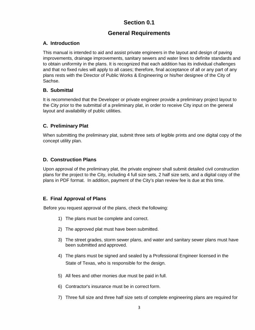
Section 0.1
General Requirements A. Introduction
This manual is intended to aid and assist private engineers in the layout and design of paving improvements, drainage improvements, sanitary sewers and water lines to definite standards and to obtain uniformity in the plans. It is recognized that each addition has its individual challenges and that no fixed rules will apply to all cases; therefore, final acceptance of all or any part of any plans rests with the Director of Public Works & Engineering or his/her designee of the City of Sachse.
B. Submittal
It is recommended that the Developer or private engineer provide a preliminary project layout to the City prior to the submittal of a preliminary plat, in order to receive City input on the general layout and availability of public utilities.
C. Preliminary Plat
When submitting the preliminary plat, submit three sets of legible prints and one digital copy of the concept utility plan.
D. Construction Plans
Upon approval of the preliminary plat, the private engineer shall submit detailed civil construction plans for the project to the City, including 4 full size sets, 2 half size sets, and a digital copy of the plans in PDF format. In addition, payment of the City’s plan review fee is due at this time.
E. Final Approval of Plans
Before you request approval of the plans, check the following:
1) The plans must be complete and correct.
2) The approved plat must have been submitted.
3) The street grades, storm sewer plans, and water and sanitary sewer plans must have been submitted and approved.
4) The plans must be signed and sealed by a Professional Engineer licensed in the
State of Texas, who is responsible for the design.
5) All fees and other monies due must be paid in full.
6) Contractor's insurance must be in correct form.
7) Three full size and three half size sets of complete engineering plans are required for
4
City use. There should be additional approved plans available for Contractors and Engineering Consultants use during construction of the improvements. The City Representative will only recognize those plans with the “approved” stamp.
8) Upon completion of construction and prior to acceptance of that construction by the City, one set of prints and a digital copy of the record drawings must be submitted to the City.
F. Specifications are the Standard Specifications for Public Work Construction, North Central Texas latest addition as prepared by the North Central Texas Council of Governments.
G. Special Provisions are City of Sachse Special Provisions to the Specifications.
H. Standard Details are as prepared by the City of Sachse and NCTCOG with City of Sachse standards having precedence over NCTCOG standard details.

5
City of Sachse, Texas
Roadway Design

6
Section 1.1
General Thoroughfare Requirements A. Introduction
The “Thoroughfare Design Standards” are intended to implement the provisions of the Subdivision Ordinance and to provide for the orderly, safe, healthy and uniform development of the area within the corporate city limits of the City of Sachse.
The City of Sachse “Standard Construction Details”, “Special Provisions” and the North Central Texas Council of Governments (NCTCOG) “Standard Specifications for Public Works Construction” are considered supplemental and are part of the Thoroughfare Design Standards. The Thoroughfare Design Standards are to be considered as the minimum requirements for engineering design. Adherence to the requirements of these standards and/or approval by the City of Sachse or its his/her designees in no way relieves the developer or his engineer for adequacy of design or for the completeness of the plans and specifications or the suitability of the completed facilities. Specific projects may require more stringent design standards. The City of Sachse may determine that design requirements other than those included in these standards are necessary and will inform the developer of such requirements before the final engineering review.
The developer shall notify the City of Sachse, in writing, of any known deviations from the requirements set for in the standards for thoroughfare design, construction details, or specifications.
B. Thoroughfare Design Standards
The Thoroughfare Design Standards are to be considered as the minimum requirements for engineering design. It is not intended that these standards cover all aspects of paving construction for any given development. The developer shall provide proper engineering design for all facilities not covered by these standards in accordance with good engineering practice and shall utilize first class workmanship and materials in all construction.
C. Special Provisions and Standard Specifications
The City of Sachse has adopted the most recent version of the NCTCOG Standard Specifications for Public Works Construction together with the Special Provisions to the Standard Specifications. These documents set forth the minimum requirements for materials and workmanship for public works construction.

7
D. Standard Construction Details
The City of Sachse has adopted a set of standard construction details in order to promote uniformity of development and to facilitate maintenance of various public works facilities. The standard construction details are to be considered as the minimum requirements for materials and workmanship for public works construction.
E. Inspection of Construction By City Personnel
Inspection of construction activities shall be conducted by staff of the City of Sachse under direction of the Director of Public Works & Engineering or his/her designee. The City inspector shall observe and check the construction in sufficient detail to satisfy himself that the work is proceeding in general conformance with the standards and specifications for the project, but he will not be a guarantor of the Contractor’s performance. The City will not accept any development until City staff has approved all construction. The developer shall be responsible for any additional expense to the City for inspection that is necessary after normal business hours, or when the improvements will be privately owned. The City has an established rate for compensation and other expenses.
The developer will be responsible for furnishing the original reproducible engineering drawings corrected to show any revised construction conditions to the City before any improvements will be accepted. All public works improvements must accepted by the before City Building permits will be issued, except as noted in the Subdivision Ordinance.
8
Section 1.2
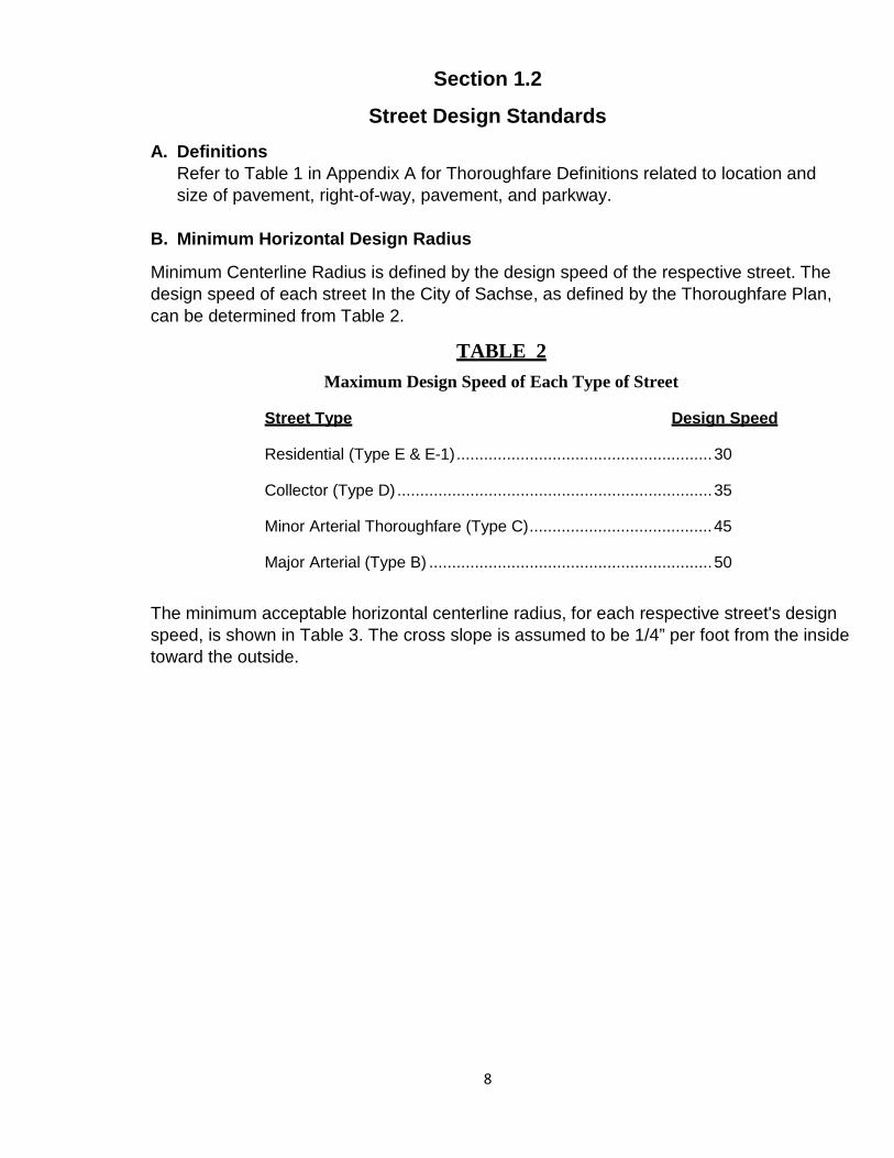
Street Design Standards A. Definitions
Refer to Table 1 in Appendix A for Thoroughfare Definitions related to location and size of pavement, right-of-way, pavement, and parkway.
B. Minimum Horizontal Design Radius
Minimum Centerline Radius is defined by the design speed of the respective street. The design speed of each street In the City of Sachse, as defined by the Thoroughfare Plan, can be determined from Table 2.
TABLE 2 Maximum Design Speed of Each Type of Street
Street Type Design Speed
Residential (Type E & E-1) ........................................................ 30
Collector (Type D) ..................................................................... 35
Minor Arterial Thoroughfare (Type C) ........................................ 45
Major Arterial (Type B) .............................................................. 50
The minimum acceptable horizontal centerline radius, for each respective street's design speed, is shown in Table 3. The cross slope is assumed to be 1/4” per foot from the inside toward the outside.
9
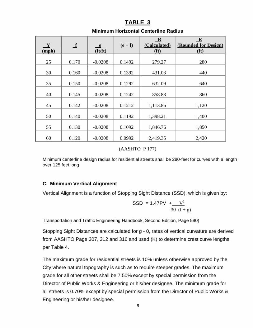
TABLE 3 Minimum Horizontal Centerline Radius
(AASHTO P 177)
Minimum centerline design radius for residential streets shall be 280-feet for curves with a length over 125 feet long
C. Minimum Vertical Alignment
Vertical Alignment is a function of Stopping Sight Distance (SSD), which is given by:
SSD = 1.47PV + V2
30 (f + g) Transportation and Traffic Engineering Handbook, Second Edition, Page 590)
Stopping Sight Distances are calculated for g - 0, rates of vertical curvature are derived from AASHTO Page 307, 312 and 316 and used (K) to determine crest curve lengths per Table 4.
The maximum grade for residential streets is 10% unless otherwise approved by the City where natural topography is such as to require steeper grades. The maximum grade for all other streets shall be 7.50% except by special permission from the Director of Public Works & Engineering or his/her designee. The minimum grade for all streets is 0.70% except by special permission from the Director of Public Works & Engineering or his/her designee.
Y (mph)
f
e (ft/ft)
(e + f)
R (Calculated)
(ft)
R (Rounded for Design)
(ft)
25
0.170
-0.0208
0.1492
279.27
280
30
0.160
-0.0208
0.1392
431.03
440
35
0.150
-0.0208
0.1292
632.09
640
40
0.145
-0.0208
0.1242
858.83
860
45
0.142
-0.0208
0.1212
1,113.86
1,120
50
0.140
-0.0208
0.1192
1,398.21
1,400
55
0.130
-0.0208
0.1092
1,846.76
1,850
60
0.120
-0.0208
0.0992
2,419.35
2,420
10
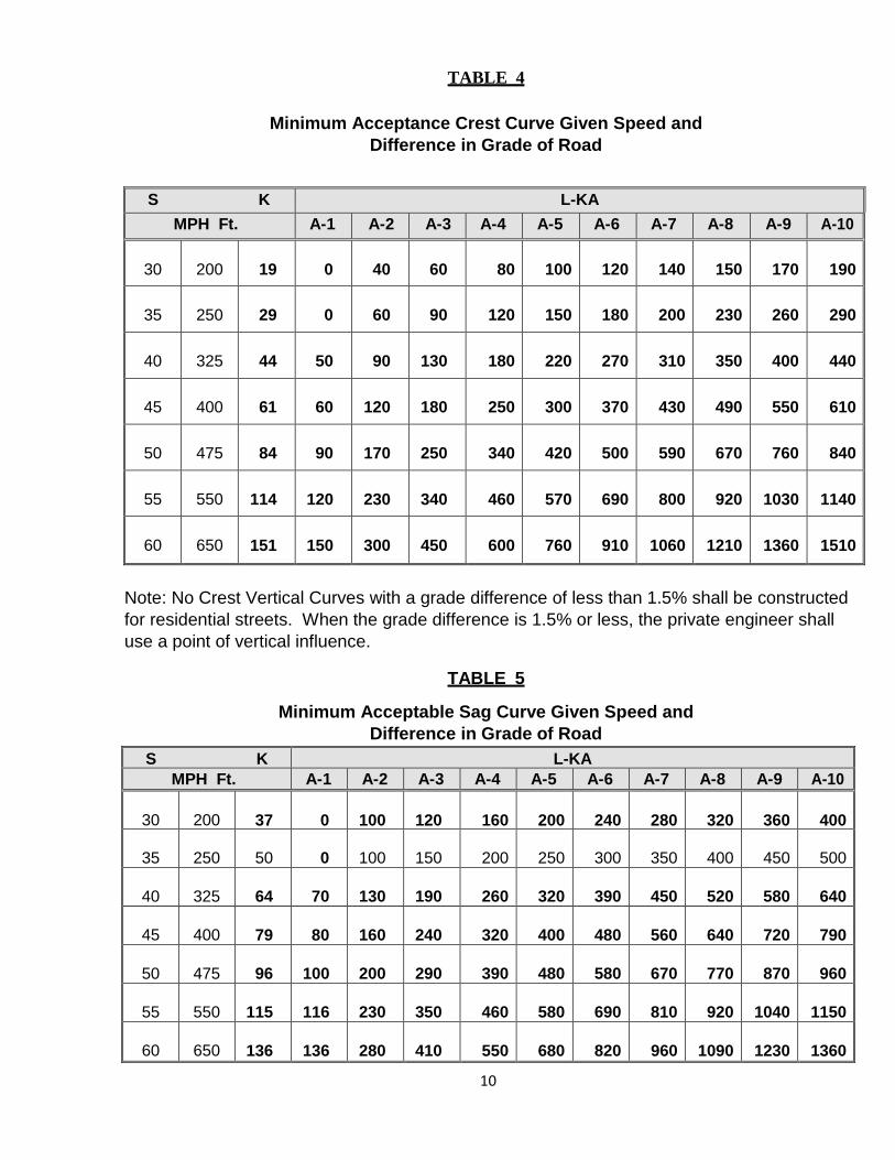
TABLE 4
Minimum Acceptance Crest Curve Given Speed and Difference in Grade of Road
S K L-KA
MPH Ft. A-1 A-2 A-3 A-4 A-5 A-6 A-7 A-8 A-9 A-10
30
200
19
0
40
60
80
100
120
140
150
170
190
35
250
29
0
60
90
120
150
180
200
230
260
290
40
325
44
50
90
130
180
220
270
310
350
400
440
45
400
61
60
120
180
250
300
370
430
490
550
610
50
475
84
90
170
250
340
420
500
590
670
760
840
55
550
114
120
230
340
460
570
690
800
920
1030
1140
60
650
151
150
300
450
600
760
910
1060
1210
1360
1510
Note: No Crest Vertical Curves with a grade difference of less than 1.5% shall be constructed for residential streets. When the grade difference is 1.5% or less, the private engineer shall use a point of vertical influence.
TABLE 5
Minimum Acceptable Sag Curve Given Speed and Difference in Grade of Road
S K L-KA MPH Ft. A-1 A-2 A-3 A-4 A-5 A-6 A-7 A-8 A-9 A-10
30
200
37
0
100
120
160
200
240
280
320
360
400
35
250
50
0
100
150
200
250
300
350
400
450
500
40
325
64
70
130
190
260
320
390
450
520
580
640
45
400
79
80
160
240
320
400
480
560
640
720
790
50
475
96
100
200
290
390
480
580
670
770
870
960
55
550
115
116
230
350
460
580
690
810
920
1040
1150
60
650
136
136
280
410
550
680
820
960
1090
1230
1360

11
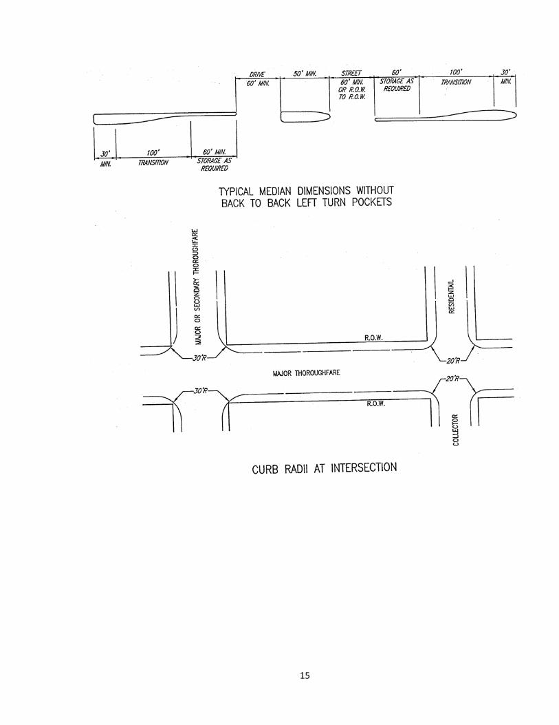
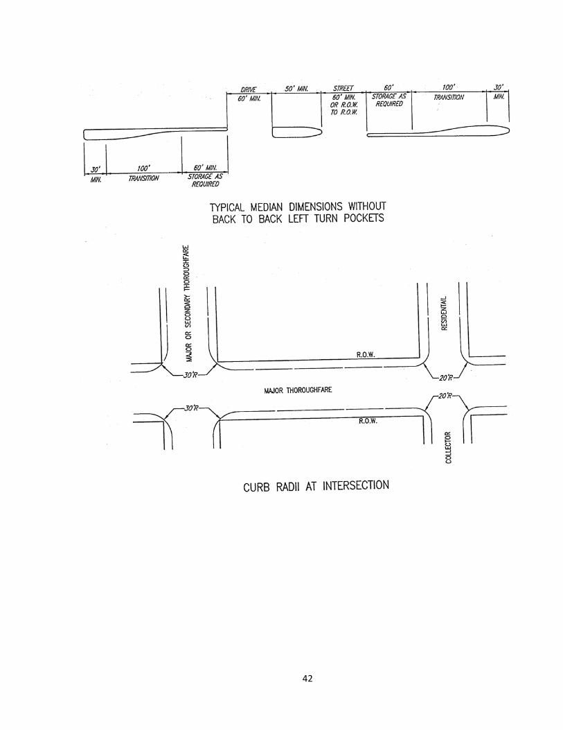
D. Intersection Curb Radii
The radius shall be thirty (30) feet at the intersection of all Major and Secondary Thoroughfare intersecting streets unless otherwise approved by the Director of Public Works & Engineering or His/her designee.
See Detail, page 10.
Note: At many intersections, the curb radius encroaches on the right-of-way so as to not provide sufficient room for sidewalks, utilities, etc. within the parkway. Therefore, right-of-way will be dedicated at the intersection of all streets such that adequate room is provided.
E. Residential Frontage
Residential houses shall not front a Major Arterial or Minor Arterial unless parallel access roads are provided. Minimum distances between adjacent curbs or the thoroughfare and the access road shall be twenty (20) feet.
F. State Designated Roads
All such roads within the City of Sachse will conform to State Design Standards unless otherwise directed by the Director of Public Works & Engineering.
12
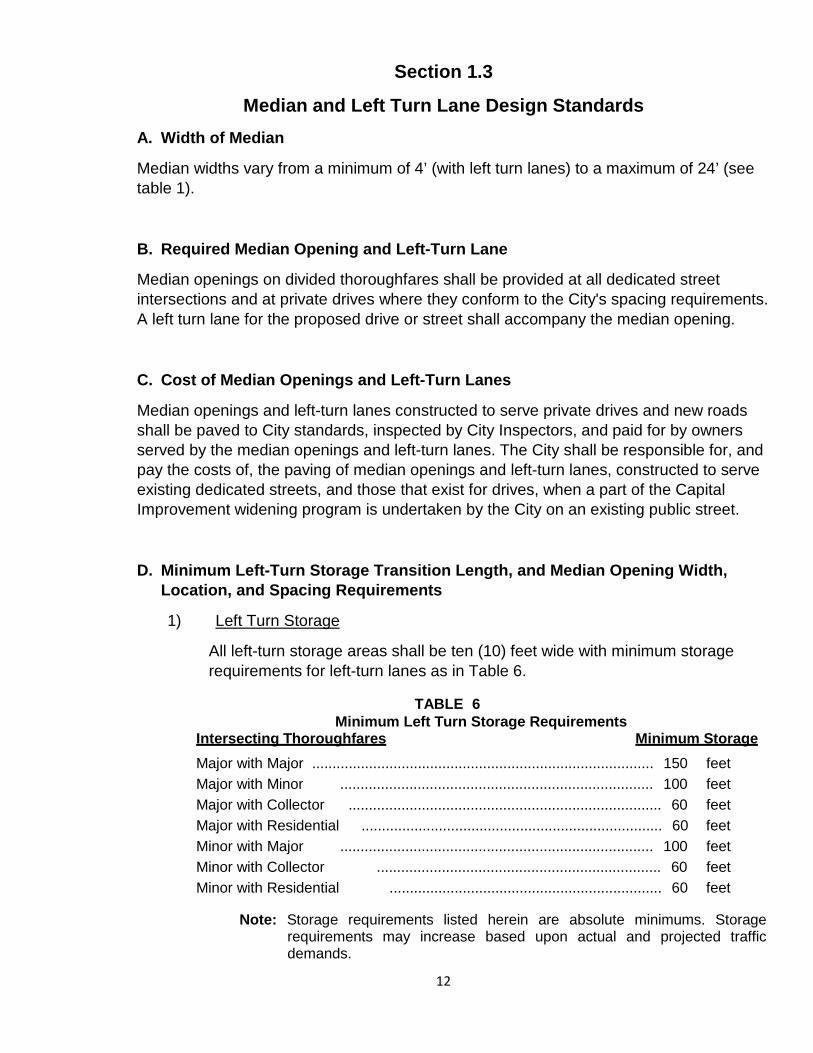
Section 1.3
Median and Left Turn Lane Design Standards A. Width of Median
Median widths vary from a minimum of 4’ (with left turn lanes) to a maximum of 24’ (see table 1).
B. Required Median Opening and Left-Turn Lane
Median openings on divided thoroughfares shall be provided at all dedicated street intersections and at private drives where they conform to the City's spacing requirements. A left turn lane for the proposed drive or street shall accompany the median opening.
C. Cost of Median Openings and Left-Turn Lanes
Median openings and left-turn lanes constructed to serve private drives and new roads shall be paved to City standards, inspected by City Inspectors, and paid for by owners served by the median openings and left-turn lanes. The City shall be responsible for, and pay the costs of, the paving of median openings and left-turn lanes, constructed to serve existing dedicated streets, and those that exist for drives, when a part of the Capital Improvement widening program is undertaken by the City on an existing public street.
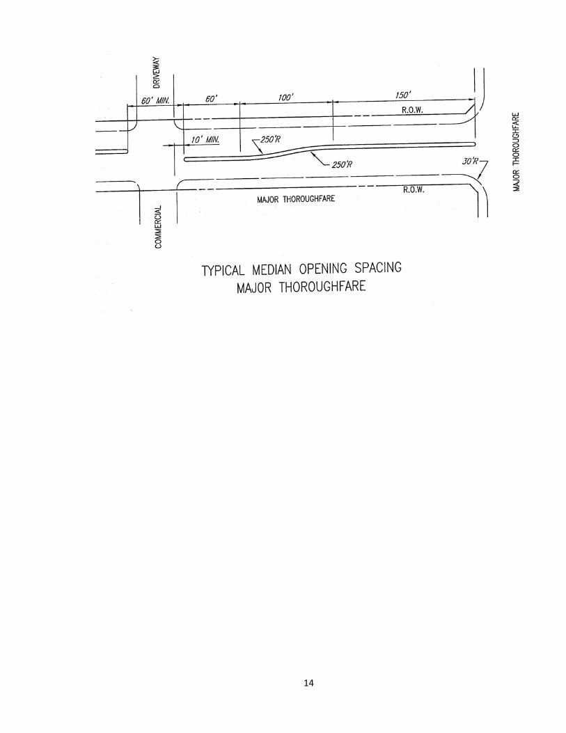
D. Minimum Left-Turn Storage Transition Length, and Median Opening Width, Location, and Spacing Requirements
1) Left Turn Storage
All left-turn storage areas shall be ten (10) feet wide with minimum storage requirements for left-turn lanes as in Table 6.
TABLE 6 Minimum Left Turn Storage Requirements
Intersecting Thoroughfares Minimum Storage Major with Major .................................................................................... 150 feet Major with Minor ............................................................................. 100 feet Major with Collector ............................................................................. 60 feet Major with Residential .......................................................................... 60 feet Minor with Major ............................................................................. 100 feet Minor with Collector ...................................................................... 60 feet Minor with Residential ................................................................... 60 feet
Note: Storage requirements listed herein are absolute minimums. Storage requirements may increase based upon actual and projected traffic demands.

13
2) Transition Length
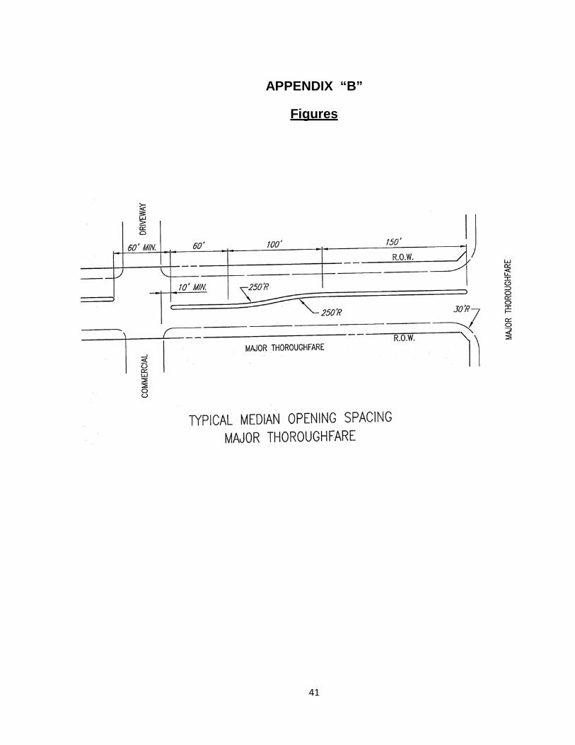
The transition curves used in left-turn lanes shall be two 250-foot radius reverse curves, which will require a total transition length of 100-feet, except by special permission from the Director of Public Works & Engineering or his/her designee.
3) Median Openings
a) Median openings at Intersections shall be from right-of-way to right-of-way or the intersecting street.
b) The minimum width of mid-block median openings shall not be less than sixty (60) feet. See Detail, page 14.
4) Medians Where No Left-Turn Pocket is Needed
a) If left-turn storage is provided in only one direction, (i.e., a drive cannot be installed for the other direction), the minimum length of median must be the required left-turn storage and transition length, plus 30-feet of median length beyond the end of the transition.
b) If the left turn storage is not required in either direction, but the median is simply a spacer between two median openings, the minimum length of the spacer must be 50- feet. See Detail, page 15.
5) Medians into Developments on Public Streets
Medians installed on undivided streets at entrances to subdivisions for aesthetic or any other purpose will be a minimum of 4-feet wide and 75-feet long.
14
15
16
Section 1.4
Alley Design Standards A. Alley Requirements for Developments
Alleys shall be constructed in accordance with City of Sachse Subdivision Ordinance. Alleys shall be paved with concrete in accordance with the City’s Standard Construction Details. Alleys may be required in commercial and industrial developments. The City may waive the commercial and industrial alley requirement upon determination of the Council, if in its opinion adequate provisions are made for service access such as off-street loading, unloading and parking consistent with the uses proposed.
B. Alley Instructions
Alleys shall not intersect major arterials. Alleys shall not intersect minor arterials with medians except with special approval by the Director of Public Works & Engineering or his/her designee. Alleys which run parallel to and share a common right-of-way line with a minor thoroughfare shall turn away from the minor street not less than one subdivision lot width or a minimum of 50-feet (whichever is greater) from the cross street intersection.
C. Alley Widths
The minimum residential alley right-of-way width shall be fifteen (15) feet with a minimum 10-foot paved width. The minimum commercial alley right-of-way width shall be fifteen (20) feet with a minimum 15-foot paved width. Dead-end alleys shall not be permitted without special permission from the Director of Public Works & Engineering or His/her designee. The geometry of alley construction shall conform to the Standard Construction Details
D. Alley Radius
Alley radii at street intersections in residential developments shall not be less than 10-feet. Alley radii at street intersections in commercial and industrial developments shall not be less than 30-feet unless approved by the Director of Public Works & Engineering or His/her designee.
17
Section 1.5
Driveway Design Standards A. Definition of Driveway Types
For purposes of interpreting the provisions of these Rules and Regulations, the following definitions shall apply:
1) A “residential” driveway provides access to a single-family residence or duplex.
These drives shall intersect residential and collector roadways only. All access to residential property abutting all other thoroughfares shall be off the alley or a service road except by special permission from the Director of Public Works & Engineering or his/her designee. All residential driveways shall be concrete except as provided in the City of Sachse Subdivision Ordinance.
2) A "commercial" driveway provides access to an office, retail or institutional
building, or to a multiple-family building. It is anticipated that such buildings will have incidental truck service. Commercial drives shall not access residential streets. All Commercial driveways shall be concrete.
3) An "industrial" driveway serves substantial numbers of truck movements to and
from loading docks of an Industrial facility, warehouse, or truck terminal. A central retail development, such as a community or regional shopping center, may have one or more driveways specially designed, signed, and located to provide access for trucks and such driveways shall be considered industrial driveways. Industrial plant driveways whose principle function is to serve administrative or employee parking lots shall be considered commercial driveways. Industrial drives shall not access residential streets. All Industrial driveways shall be concrete.
Note: Two-way driveways shall always be designed to intersect the street at a 90o
angle. One-way driveways may be designed to intersect a street at a 45o angle.
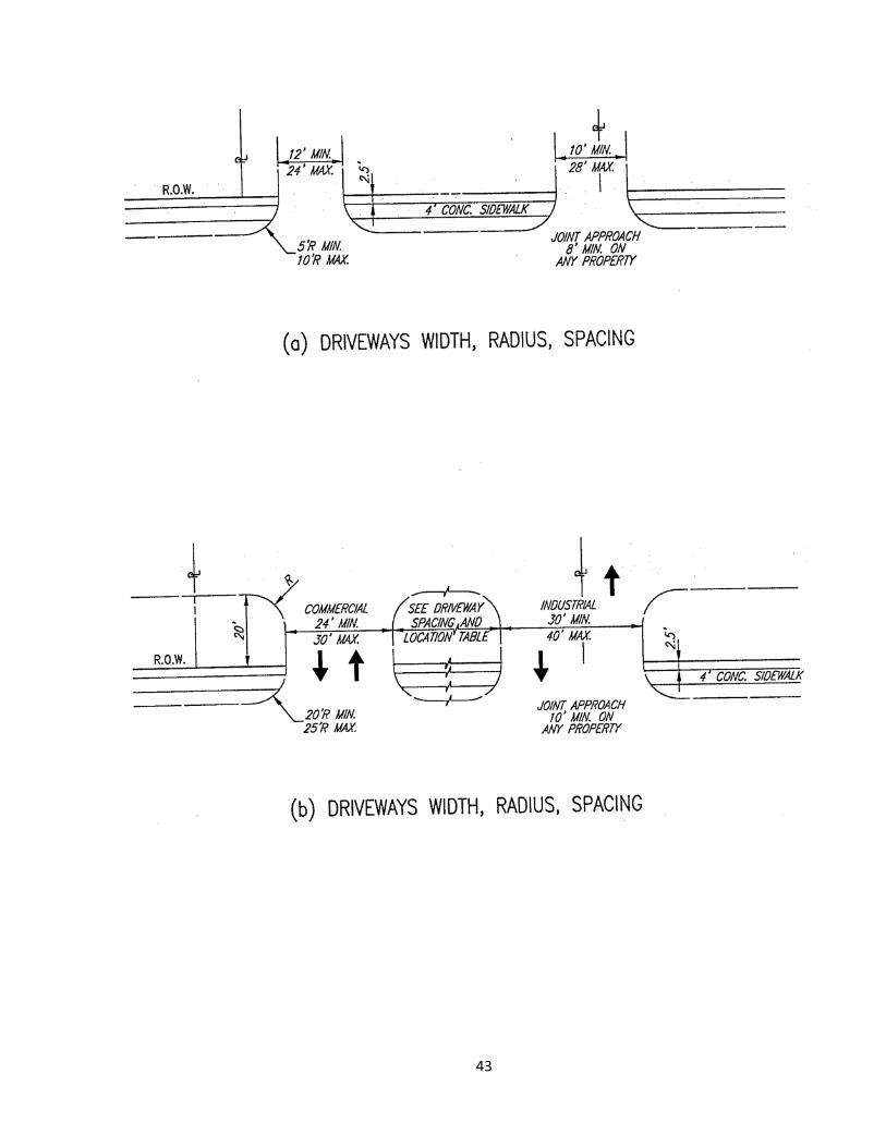
B. Driveway Width
As the term is used here, the width of a driveway refers to the width of pavement at the property line.
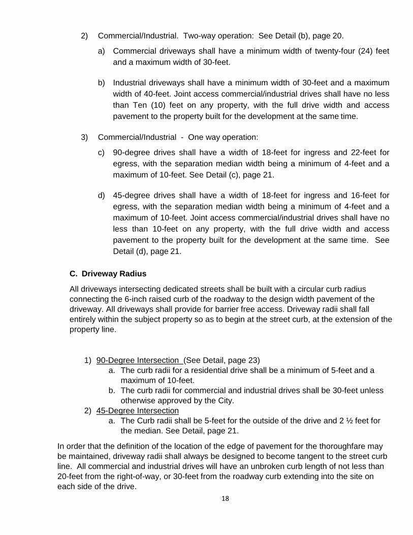
1) Residential driveways onto streets shall have a minimum width of 12-feet and a maximum width of 24-feet. Joint access residential drives shall have no less than nine (9) feet on any property. See Detail (a), page 20.
18
2) Commercial/Industrial. Two-way operation: See Detail (b), page 20.
a) Commercial driveways shall have a minimum width of twenty-four (24) feet and a maximum width of 30-feet.
b) Industrial driveways shall have a minimum width of 30-feet and a maximum
width of 40-feet. Joint access commercial/industrial drives shall have no less than Ten (10) feet on any property, with the full drive width and access pavement to the property built for the development at the same time.
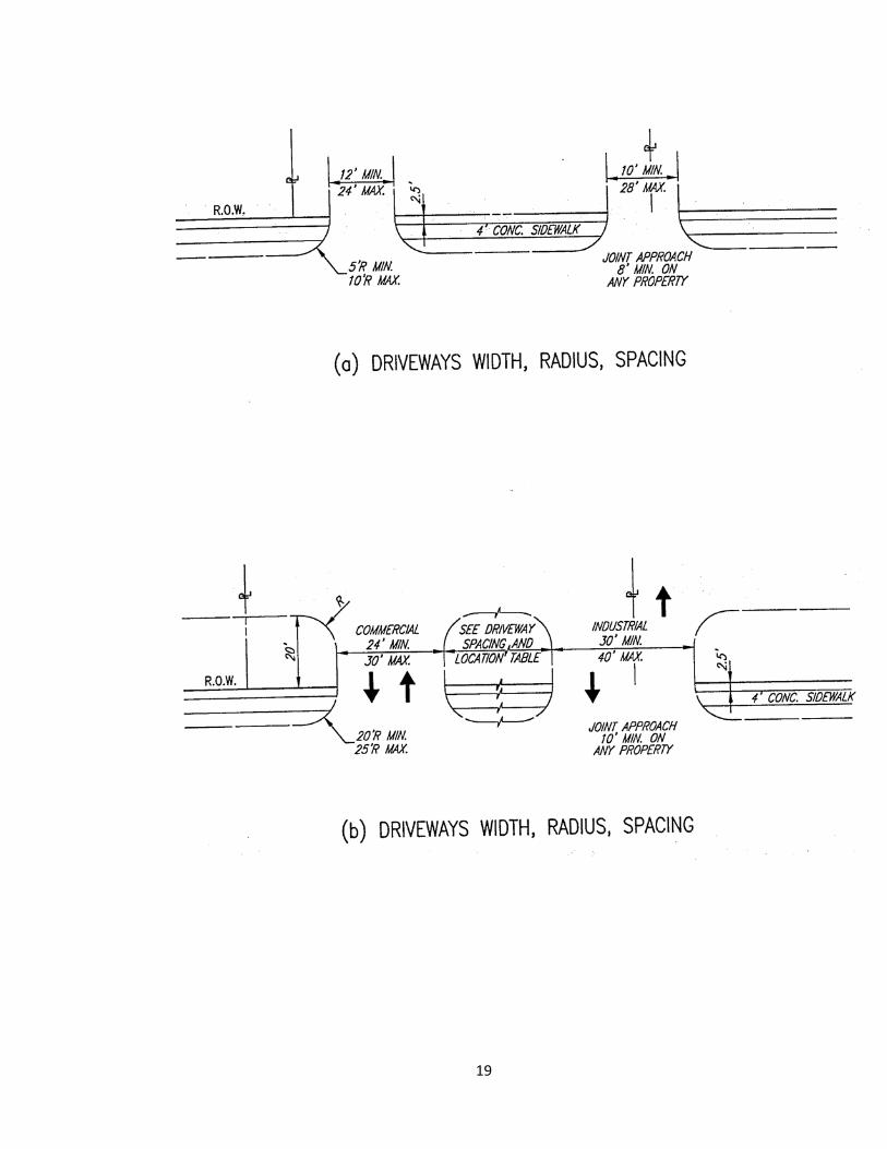
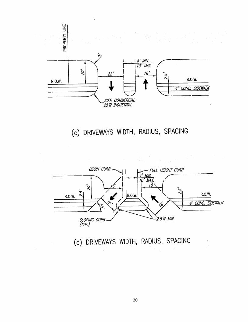
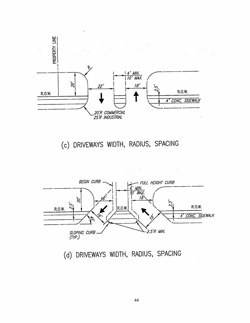
3) Commercial/Industrial - One way operation:
c) 90-degree drives shall have a width of 18-feet for ingress and 22-feet for egress, with the separation median width being a minimum of 4-feet and a maximum of 10-feet. See Detail (c), page 21.
d) 45-degree drives shall have a width of 18-feet for ingress and 16-feet for
egress, with the separation median width being a minimum of 4-feet and a maximum of 10-feet. Joint access commercial/industrial drives shall have no less than 10-feet on any property, with the full drive width and access pavement to the property built for the development at the same time. See Detail (d), page 21.
C. Driveway Radius
All driveways intersecting dedicated streets shall be built with a circular curb radius connecting the 6-inch raised curb of the roadway to the design width pavement of the driveway. All driveways shall provide for barrier free access. Driveway radii shall fall entirely within the subject property so as to begin at the street curb, at the extension of the property line.
1) 90-Degree Intersection (See Detail, page 23) a. The curb radii for a residential drive shall be a minimum of 5-feet and a
maximum of 10-feet. b. The curb radii for commercial and industrial drives shall be 30-feet unless
otherwise approved by the City. 2) 45-Degree Intersection
a. The Curb radii shall be 5-feet for the outside of the drive and 2 ½ feet for the median. See Detail, page 21.
In order that the definition of the location of the edge of pavement for the thoroughfare may be maintained, driveway radii shall always be designed to become tangent to the street curb line. All commercial and industrial drives will have an unbroken curb length of not less than 20-feet from the right-of-way, or 30-feet from the roadway curb extending into the site on each side of the drive.
19
20
21
D. Driveway Spacing and Location in Relation to Other Drives
1) Residential
Driveway approaches on a tract of land devoted to one use shall not occupy more than 70% of the frontage abutting the roadway. No more than two driveway approaches shall be permitted on any parcel of property on each street.
2) Commercial and Industrial
The spacing and location of driveways shall be related to both existing adjacent driveways and those shown on approved development plans. The spacing between driveways shall depend upon the design speed of the street as shown Table 7. Driveways shall not be permitted in the transition area of a deceleration lane or a right turn lane.
TABLE 7
Driveway Spacing in Relation to Other Drives Given the Design Speed of the Street
Design Speed (MPH) Driveway Spacing (Ft.)
30 ............................................................................................... 90
35 ............................................................................................. 100
40 ............................................................................................. 120
45 ............................................................................................. 150
50 ............................................................................................. 200
The minimum spacing shall not be more than 10-feet less than shown above. Spacing between driveways will be measured along the property line from the edge of one driveway to the closest edge of the next driveway and not from centerline to centerline.
22
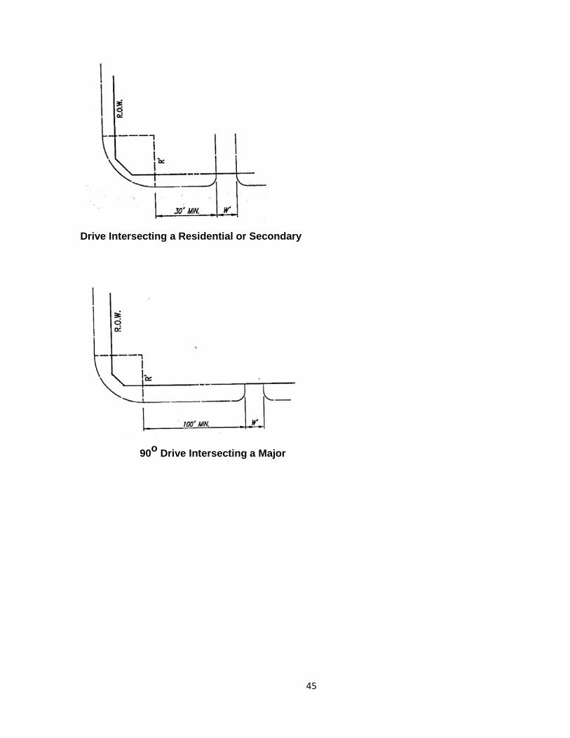
E. Driveway Spacing in Relation to a Cross Street
1) 90 Degree Intersection - Drive to Road
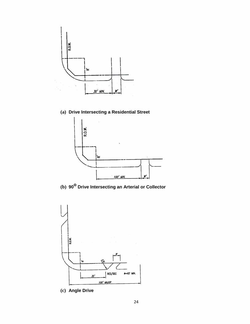
a) Driveways that intersect at 90 degrees to a residential street shall be located a minimum of the drive radius from a residential street's end of curb radius.
b) A residential driveway that intersects at 90 degrees to a collector shall be
located a minimum of thirty (30) feet from an end of curb radius. (see Detail (a), page 25)
c) A commercial or industrial driveway that intersects at 90 degrees to an arterial
or collector shall be located a minimum of 100-feet from any intersecting street's right-of-way or from the end of any intersecting street's curb radius as determined by the Director of Public Works & Engineering. If the property length, along the street, is such that both the drive and the drive's curb radius cannot be totally within the proposed development, the drive will be situated so as to be a joint access drive. (see Detail (b), page 25)
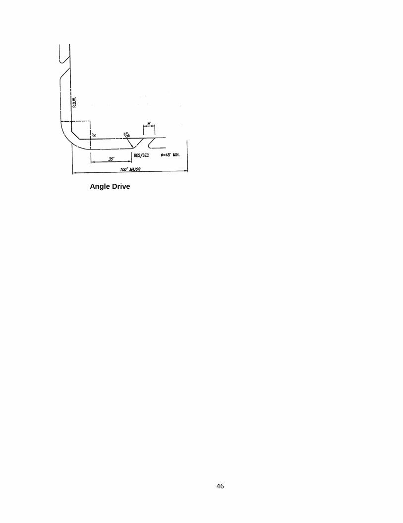
2) 45 degree Intersection - Drive to Road
a) If one-way angle drives are used, the radius for the driveway may not begin less than 35-feet from an intersecting street's end of curb radius.
b) On an arterial or collector the drive shall be located a minimum of 100-feet from
any intersecting street's right-of-way. If a property length, along the street, is such that both the drive and drive's curb radius cannot be totally within the proposed development, the drive will be situated so as to be a joint access drive. (see Detail (c), page 23)
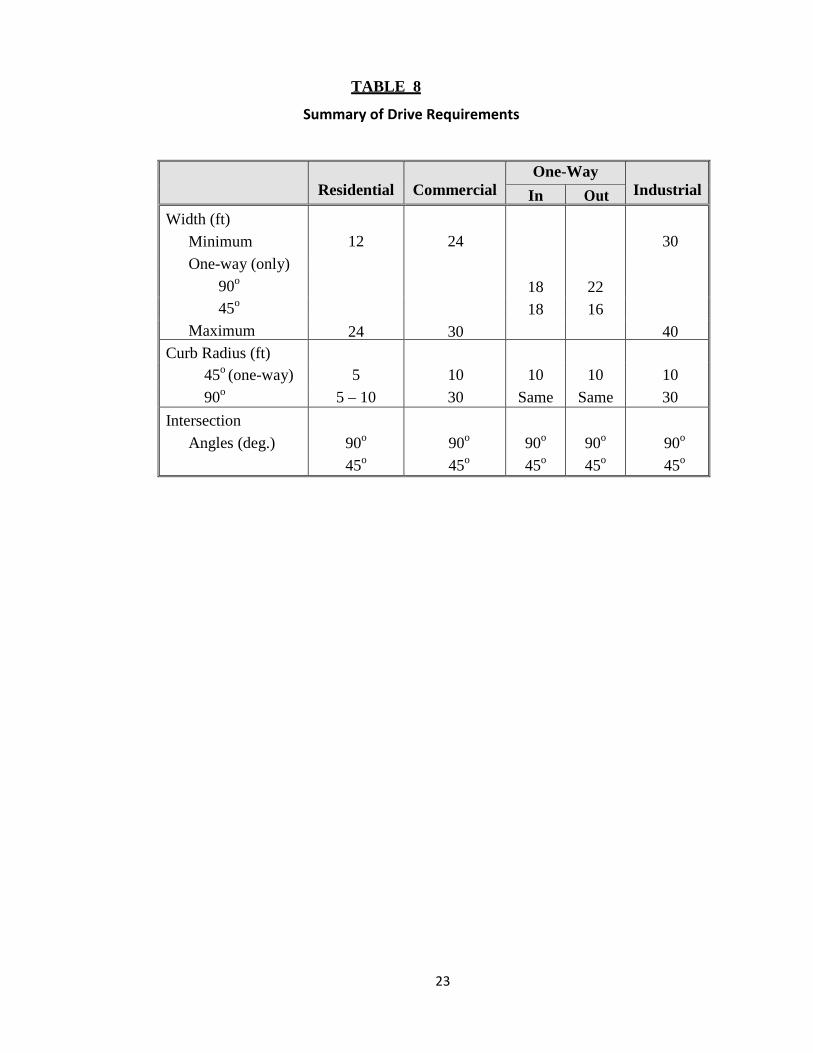
A summary of driveway widths, radii, and angle requirements are given in Table 8.
23
TABLE 8
Summary of Drive Requirements
Residential
Commercial
One-Way Industrial In Out
Width (ft) Minimum One-way (only)
90o
45o
Maximum
12
24
30
18 22
18 16
24 30 40 Curb Radius (ft)
45o (one-way) 5 10 10 10 10 90o
5 – 10 30 Same Same 30 Intersection
Angles (deg.)
90o
45o
90o
45o
90o
45o
90o
45o
90o
45o
24
(a) Drive Intersecting a Residential Street
(b) 90o Drive Intersecting an Arterial or Collector
(c) Angle Drive
25
Section 1.6
Sidewalk and Location Design Standards A. Definition of Sidewalk
A sidewalk is defined as that paved area in a roadway right-of-way between the curb lines or the edge of pavement or the roadway and the adjacent property lines for the use of pedestrians. The maximum cross slope of the sidewalk shall be ¼-inch per foot. These sidewalks shall conform to the following standards:
1) Zoning Classification Requiring Sidewalks: Concrete sidewalks designed and
located according to City standards shall be constructed along all streets in all zoning classifications except agricultural zoning. The Owner shall build sidewalks at the time of site development. Should it be impractical to install the sidewalk at that time, funds for the sidewalk construction shall be placed in escrow with the City for use at a future date. Payment or escrow shall be made in accordance with the City of Sachse Subdivision Ordinance.
2) Residential Areas (Single Family, Two Family): Sidewalks shall be a minimum of
4-feet in width and located 1-foot from the right-of-way line, except as provided for in the City of Sachse Subdivision Ordinance and Zoning Ordinance. Along thoroughfares with inadequate right-of-way the sidewalk width shall be 5-feet in width and constructed adjacent to the back of curb.
3) Non-Residential Areas: Sidewalks shall be 5-feet in width and located 1-foot from
the right-of-way line. Along thoroughfares with inadequate right-of-way the sidewalk width shall be 6-feet in width and constructed adjacent to the back of curb.
4) Exceptions: In areas where mailboxes interfere with a clear width of 4 or 5 feet for
the sidewalk, the specified width shall be wrapped around the mailbox.
5) Waiver: The sidewalk required in non-residential areas may be waived by the City Council either temporarily or permanently at the time of site plan or final plat approval. Waiver may be granted based on site conditions and/or location of the tract.
26
6) Areas Without Screening Walls: In areas on arterial and collector roads where either screening is not required or a type of screening other than a wall is used, (e.g., a berm, foliage, etc.) a 5-foot sidewalk will be constructed not more than 2½-feet from the right- of-way line as required by the Thoroughfare Plan.
7) Areas with Screening Walls: In areas where a screening wall is provided, a concrete sidewalk shall be constructed contiguous with the screening wall. The street side of the sidewalk shall run parallel to the street curb. The sidewalk shall be a minimum of 5-feet wide and the measurement shall be made from the street side of the sidewalk.
8) Sidewalk on Bridges: Bridges on thoroughfares shall have a sidewalk constructed on each side of the bridge. The sidewalk shall be a minimum of 6-feet wide with a parapet wall provided adjacent to the curb of the thoroughfare and with a standard pedestrian bridge rail protecting the sidewalk on the outside edge of the bridge.
9) Sidewalks under Bridges: When new bridges are built as a part of the construction of a roadway or the reconstruction of a roadway and a pedestrian crossing is needed, a sidewalk or shared use path will be built as a part of the embankment design underneath the bridge structure in accordance with the City of Sachse Trail Master Plan. The sidewalk or shared use path shall be located generally along the toe of the embankment.
B. Barrier Free Ramps (Compliance shall be with the American Disability Act)
Curbs and walks constructed at intersections or all streets and thoroughfares must comply with the provisions of the American Disability Act and be constructed in a manner to be easily and safely negotiated by physically challenged persons.
27
Section 1.7
Public Right of Way Visibility A. Street/Drive Intersection Visibility Obstruction Triangles- Frontage Plan/ Profile
A landscape plan showing the plan/profile of the street on both sides of each proposed drive/street to the proposed development with the grades, curb elevations, proposed street/drive locations, and all Items (both natural and man-made) within the visibility triangles as prescribed below shall be provided with all engineering plan submittals. This profile shall show no horizontal or vertical restrictions (either existing or future) within the areas defined below.
1) Obstruction/Interference Triangles-Defined
No fence, wall, screen, billboard, sign, structure, foliage, hedge, tree, bush, shrub, berm, or any other item, either manmade or natural shall be erected, planted, or maintained in a position, which will obstruct or interfere with the following minimum standards.
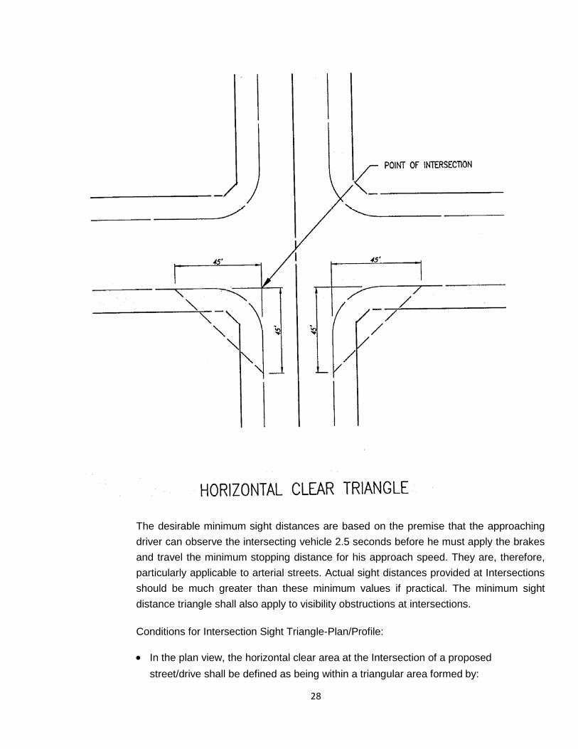
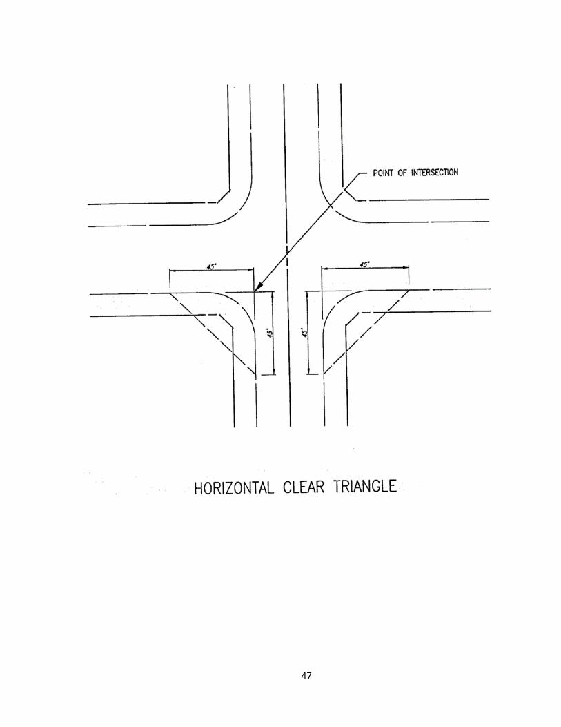
a) Vision at all intersections where streets intersect at or near right angles shall be
clear at elevation between 2½-feet and 9-feet above the average gutter elevation, except single trunk trees, within a triangular area formed by extending the two curb lines from their point of intersection, 45-feet, and connecting these points with an imaginary line, thereby making a triangle. If there are no curbs existing, the triangular area shall be formed by extending the property lines from their point of intersection 30-feet and connecting these points with an imaginary line, thereby making a triangle. (see Detail, page 23)
b) Definitions for desirable minimum sight distance requirements for non-
residential streets, commercial driveways, and industrial driveways that intersect at or near right angles are presented below (see Detail, page 25). The values presented are minimum sight distances which would permit the following:
• T-Upon turning left or right, an existing vehicle could accelerate to the
operating speed of the street.
28
The desirable minimum sight distances are based on the premise that the approaching driver can observe the intersecting vehicle 2.5 seconds before he must apply the brakes and travel the minimum stopping distance for his approach speed. They are, therefore, particularly applicable to arterial streets. Actual sight distances provided at Intersections should be much greater than these minimum values if practical. The minimum sight distance triangle shall also apply to visibility obstructions at intersections.
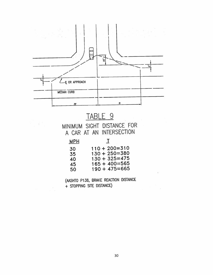
Conditions for Intersection Sight Triangle-Plan/Profile:
• In the plan view, the horizontal clear area at the Intersection of a proposed
street/drive shall be defined as being within a triangular area formed by:
29
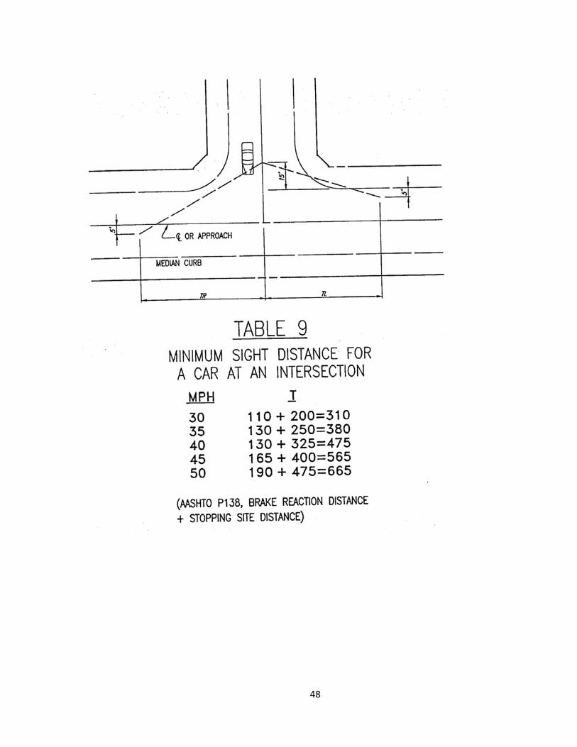
(I) A line that is on the centerline of the proposed street/drive, beginning at the
Intersecting street's tangent curb and continuing for a distance of 15-feet back into the proposed street/drive to the end point.
(II) A line that is parallel to and 5-feet out from the intersecting street's curb,
beginning at the centerline of the proposed street/drive and continuing for a distance "T" as prescribed in Table 9, to the end point.
(III) A straight line that connects the end point of an:
• That is on the centerline and 15-feet back into the proposed street/drive, and the end point of a
• That is a distance “T” along and 5-feet out from the existing street's curb from the centerline or the proposed street/drive.
In the profile view, the clear window shall be defined as being within the horizontal clear area and clear between 2.5 feet and 9 feet above the average pavement elevation.
Note: Single trunk trees within the triangles and in the median shall be allowed and spaced
so as to not cause a "picket fence" effect. Because of the large variation of ways in which trees can be planted, the spacing will be decided upon by the Director of Public Works & Engineering and the developer at the time of review of the landscape plans. Any other item that obstructs these lines so as to interfere with the above requirements will not be allowed.
30

31
TABLE 9
Minimum Sight Distance For a Car at Intersection
(For Level-Two Lane Streets)
MPH T 30 ..................................................................... 110 + 200 = 310
35 ..................................................................... 130 + 250 = 380
40 ..................................................................... 130 + 325 = 475
45 ..................................................................... 165 + 400 = 565
50 ..................................................................... 190 + 475 = 665
AASHTO P138, Break Reaction Distance + Stopping Site Distance
The aforementioned restrictions also apply to streets that do not intersect at right angles, except that the triangle dimensions shall not necessarily be minimum requirements. In such cases the Director of Public Works & Engineering shall have the authority to vary such requirements as he deems necessary to provide safety for both vehicular and pedestrian traffic.
B. R.O.W. Obstructions Outside the Visibility Triangles
1) Foliage of hedges, trees and shrubs in public right-of-ways which are not governed by Zoning Ordinance of the City, or the above triangles shall be maintained such that the minimum overhung above a sidewalk shall be 7-feet; the minimum overhang above a street shall be 14-feet.
2) All other areas within the street right-of-ways shall be clear at elevations between 2½-feet and 9-feet above the average street grade,
3) Plants in the public right-of-way that will grow over 30-inches (when mature) above the adjacent street's curb will conform to all of the above requirements, where applicable. All landscape plans shall show the locations and type of such plants, and show each of the prescribed triangles.
4) Ground elevations, within both triangles, will be shown by contour lines.
Note: No plantings over 30-inches above the adjacent gutter elevation are allowed in the median for the length of the left turn stacking space unless specifically agreed upon by the Director of Public Works & Engineering.
32
C. Alley Visibility Obstructions
No fence, wall, screen, billboard, sign, structure, or foliage of hedges, trees, bushes, or shrubs shall be erected, planted or maintained in any alley right-of-way. Foliage or hedges, trees, bushes, and shrubs planted adjacent to the alleys right-of-way which are not governed by the above triangles or by Zoning Ordinance of the City, shall be maintained such that the minimum overhang or encroachment shall be 14-feet above the alley surface at the edge of the pavement.
D. Exceptions
The provisions of this manual shall not apply to, or otherwise interfere with, the following:
1) Placement and maintenance of traffic control devices under governmental authority and control.
2) Existing and future screening requirements Imposed by the City Council.
3) Existing and future City, State and Federal Regulations.
33
Section 1.8
Off Street Requirements A. Stacking Space For Drive-Up Windows
The minimum stacking space for the first vehicle stop for a commercial drive-through shall be 100-feet, and 40-feet thereafter, for any other stops.
B. Parking- Lot Layout
1) All parking lots shall be paved with concrete unless otherwise approved by City Council.
2) No parking area will be allowed to dead-end unless adequate turnaround space is proved.
3) Each standard 90⁰ off-street parking space shall measure not less than 9 feet by 18 feet, exclusive of access drives and aisles, and shall be of usable shape and condition. One-way angled parking shall measure not less than 9.5 feet by 18 feet.
4) The width for two-way aisles shall be a minimum of 24-feet and a maximum of 45-feet. The width for one-way aisles shall be a minimum of 20-feet (24-feet if the aisle is also a fire lane).
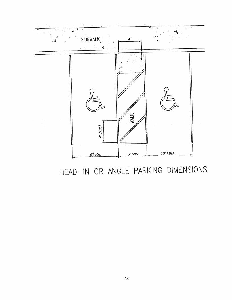
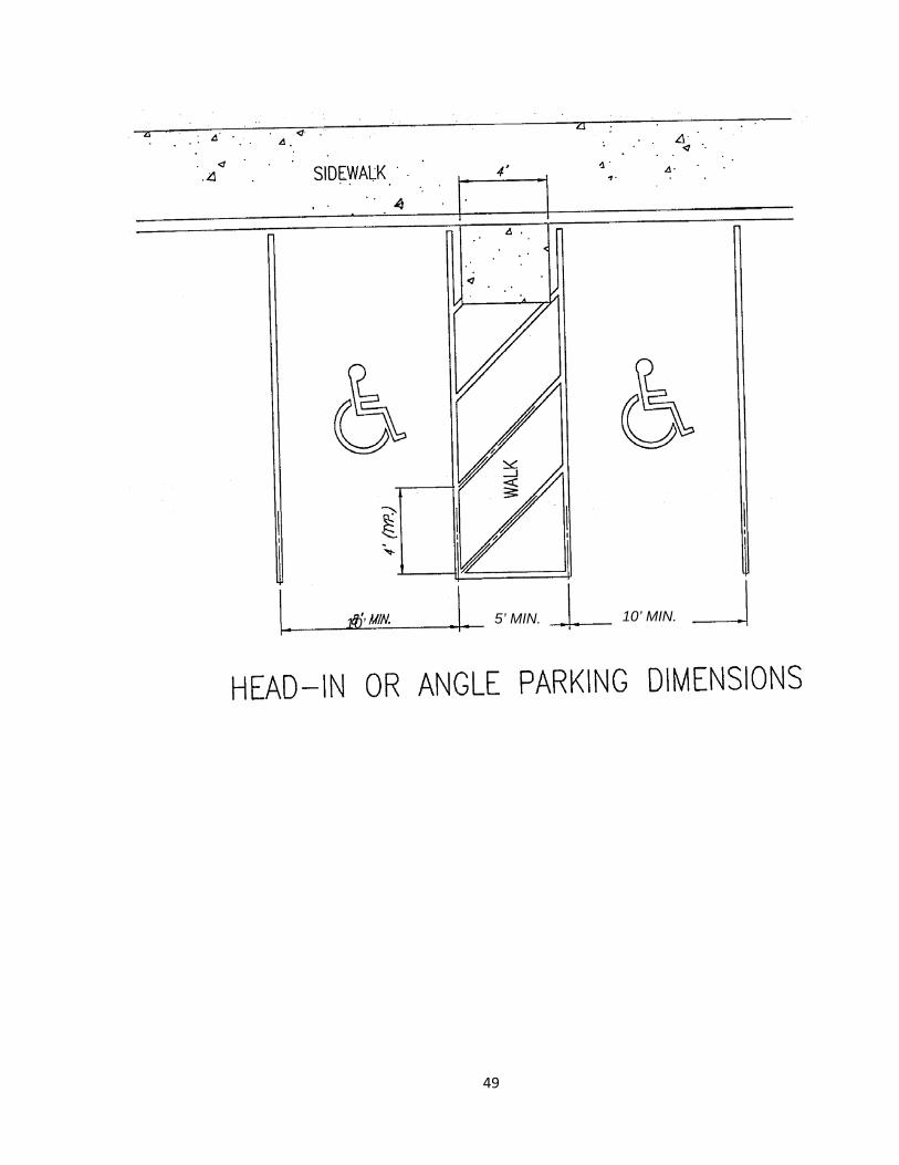
5) Handicapped parking spaces shall be minimum 10-feet in width with a 5-foot minimum walkway. The walkway can be shared by two spaces. For parallel parking the space shall be a minimum of 24-feet by a minimum 13-feet with a 3-foot minimum walkway one end in addition to the minimum 24-foot dimension. (see Detail, page 29)
6) Parking Overhang: No parking stall shall be situated so as to allow vehicle overhand into public right-of-way. Curb or parking stops shall be installed so that the distance between the face of the curb or car stop is a minimum of 2-feet from the public right-of-way.
7) Movements in Public Right-of-Way: No parking stall shall be so designed as to allow any movement into or out of the stall, upon public right-of-way.
8) Parking lot illumination shall be designed and constructed to direct the light to the parking lot and away from any adjoining property or street.
9) Fire lanes shall be constructed as required by Fire Department rules and regulations.
34
10’
10’ MIN. 5’ MIN.

35
APPENDIX “A”
Tables

36
37
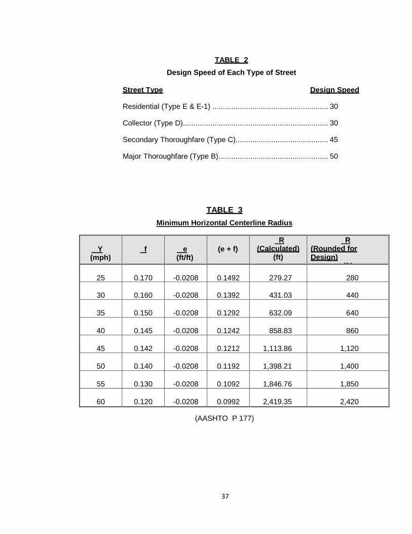
TABLE 2 Design Speed of Each Type of Street
Street Type Design Speed
Residential (Type E & E-1) ....................................................... 30
Collector (Type D) ..................................................................... 30
Secondary Thoroughfare (Type C)............................................ 45
Major Thoroughfare (Type B) .................................................... 50
TABLE 3 Minimum Horizontal Centerline Radius
Y (mph)
f
e (ft/ft)
(e + f)
R (Calculated)
(ft)
R (Rounded for Design)
(ft) 25
0.170
-0.0208
0.1492
279.27
280
30
0.160
-0.0208
0.1392
431.03
440
35
0.150
-0.0208
0.1292
632.09
640
40
0.145
-0.0208
0.1242
858.83
860
45
0.142
-0.0208
0.1212
1,113.86
1,120
50
0.140
-0.0208
0.1192
1,398.21
1,400
55
0.130
-0.0208
0.1092
1,846.76
1,850
60
0.120
-0.0208
0.0992
2,419.35
2,420
(AASHTO P 177)

38
TABLE 4
Minimum Acceptable Crest Curve Given Speed and Difference in Grade of Road
S K L-KA MPH Ft. A-1 A-2 A-3 A-4 A-5 A-6 A-7 A-8 A-9 A-10
30
200
19
0
40
60
80
100
120
140
150
170
190
35
250
29
0
60
90
120
150
180
200
230
260
290
40
325
44
50
90
130
180
220
270
310
350
400
440
45
400
61
60
120
180
250
300
370
430
490
550
610
50
475
84
90
170
250
340
420
500
590
670
760
840
55
550
114
120
230
340
460
570
690
800
920
1030
1140
60
650
151
150
300
450
600
760
910
1060
1210
1360
1510
TABLE 5
Minimum Acceptable Sag Curve Given Speed and Difference in Grade of Road
S K L-KA MPH Ft. A-1 A-2 A-3 A-4 A-5 A-6 A-7 A-8 A-9 A-10
30
200
37
0
100
120
160
200
240
280
320
360
400
35
250
50
0
100
150
200
250
300
350
400
450
500
40
325
64
70
130
190
260
320
390
450
520
580
640
45
400
79
80
160
240
320
400
480
560
640
720
790
50
475
96
100
200
290
390
480
580
670
770
870
960
55
550
115
116
230
350
460
580
690
810
920
1040
1150
60
650
136
136
280
410
550
680
820
960
1090
1230
1360
39
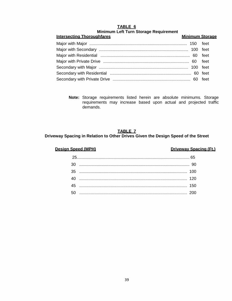
TABLE 6 Minimum Left Turn Storage Requirement
Intersecting Thoroughfares Minimum Storage Major with Major .................................................................................... 150 feet Major with Secondary ............................................................................. 100 feet Major with Residential ............................................................................. 60 feet Major with Private Drive .......................................................................... 60 feet Secondary with Major ............................................................................. 100 feet Secondary with Residential ...................................................................... 60 feet Secondary with Private Drive ................................................................... 60 feet
Note: Storage requirements listed herein are absolute minimums. Storage requirements may increase based upon actual and projected traffic demands.
TABLE 7 Driveway Spacing in Relation to Other Drives Given the Design Speed of the Street
Design Speed (MPH) Driveway Spacing (Ft.)
25 ............................................................................................... 65
30 ............................................................................................... 90
35 ............................................................................................. 100
40 ............................................................................................. 120
45 ............................................................................................. 150
50 ............................................................................................. 200
40
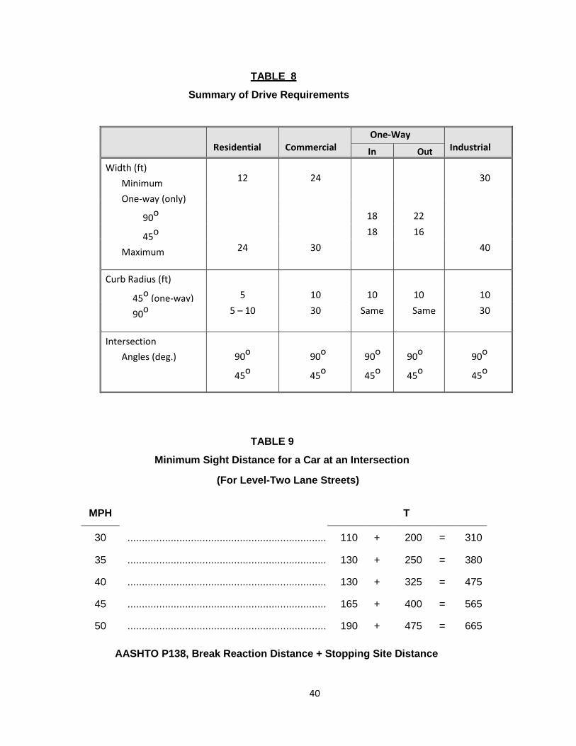
TABLE 8
Summary of Drive Requirements
Residential
Commercial One-Way
Industrial In Out Width (ft)
Minimum One-way (only)
90o
45o
Maximum
12
24
30
18 22
18 16
24 30 40
Curb Radius (ft)
45o (one-way) 5 10 10 10 10
90o 5 – 10 30 Same Same 30
Intersection Angles (deg.)
90o
45o
90o
45o
90o
45o
90o
45o
90o
45o
TABLE 9
Minimum Sight Distance for a Car at an Intersection
(For Level-Two Lane Streets)
MPH T
30 ..................................................................... 110 + 200 = 310
35 ..................................................................... 130 + 250 = 380
40 ..................................................................... 130 + 325 = 475
45 ..................................................................... 165 + 400 = 565
50 ..................................................................... 190 + 475 = 665
AASHTO P138, Break Reaction Distance + Stopping Site Distance
41
APPENDIX “B”
Figures
42
43
44
45
Drive Intersecting a Residential or Secondary
90o Drive Intersecting a Major
46
Angle Drive
47
48
49
10’
10’ MIN. 5’ MIN.

50
City of Sachse, Texas
Water & Sanitary Sewer Design
51
Section 2.1
Water Mains
In general, water mains are placed as shown in the Standard Construction Details, or otherwise as directed by the Director of Public Works & Engineering. Where applicable, line sizes will comply with the Water Distribution System Master Plan and shall be adequate to convey a fire flow. Fire flow analysis will be required on lines that are questioned by City staff. Starting pressures shall be obtained from the nearest junction node as stated in the City’s Water Distribution Master Plan computer printouts or shall be provided by the City.
A. Minimum 8-inch pipe required in residential areas. B. Minimum 12-inch pipe required on commercial, retail and industrial areas, except by
special permission from the Director of Public Works & Engineering or his/her designee. C. The length of dead-end mains shall not exceed 600 feet. A Fire Hydrant will be required
at the end of the main. D. No water main shall be located closer than 5-feet from any tree or structure. E. Crosses shall not be used without permission from the Director of Public Works &
Engineering or his/her designee.
F. Water Main Specifications:
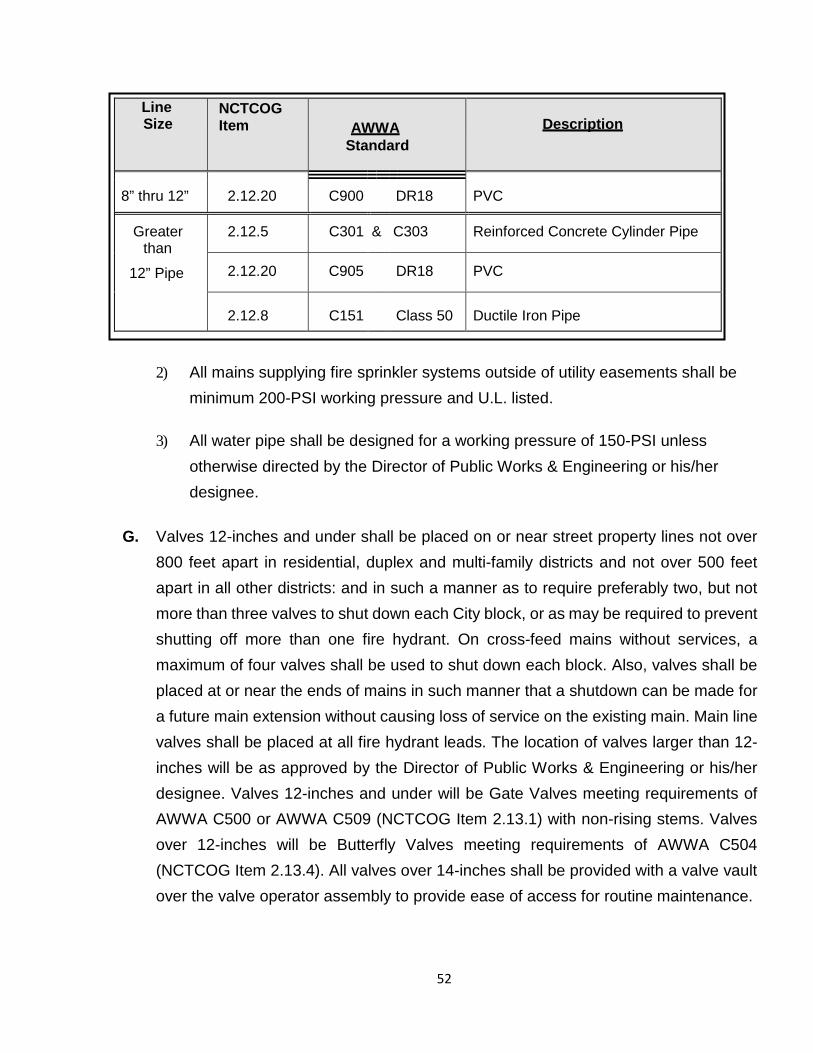
1) City mains shall have a minimum diameter of 8-inches, unless a larger line size is required by the Comprehensive Plan, Water Master Plan or to meet fire protection needs as determined by analysis. All water lines shall meet the requirements of AWWA and NCTCOG under the specifications shown on the following page.
52
Line Size
NCTCOG Item
AWWA
Standard
Description
8” thru 12” 2.12.20 C900 DR18 PVC
Greater than
12” Pipe
2.12.5 C301 & C303 Reinforced Concrete Cylinder Pipe
2.12.20 C905 DR18 PVC
2.12.8 C151
Class 50 Ductile Iron Pipe
2) All mains supplying fire sprinkler systems outside of utility easements shall be minimum 200-PSI working pressure and U.L. listed.
3) All water pipe shall be designed for a working pressure of 150-PSI unless
otherwise directed by the Director of Public Works & Engineering or his/her designee.
G. Valves 12-inches and under shall be placed on or near street property lines not over
800 feet apart in residential, duplex and multi-family districts and not over 500 feet apart in all other districts: and in such a manner as to require preferably two, but not more than three valves to shut down each City block, or as may be required to prevent shutting off more than one fire hydrant. On cross-feed mains without services, a maximum of four valves shall be used to shut down each block. Also, valves shall be placed at or near the ends of mains in such manner that a shutdown can be made for a future main extension without causing loss of service on the existing main. Main line valves shall be placed at all fire hydrant leads. The location of valves larger than 12-inches will be as approved by the Director of Public Works & Engineering or his/her designee. Valves 12-inches and under will be Gate Valves meeting requirements of AWWA C500 or AWWA C509 (NCTCOG Item 2.13.1) with non-rising stems. Valves over 12-inches will be Butterfly Valves meeting requirements of AWWA C504 (NCTCOG Item 2.13.4). All valves over 14-inches shall be provided with a valve vault over the valve operator assembly to provide ease of access for routine maintenance.
53
H. Fire Hydrants Section 1. Number and Locations
A sufficient number of fire hydrants shall be installed to provide hose stream protection for every point on the exterior wall of the building with the lengths of hose normally attached to the hydrants. There shall be sufficient hydrants to concentrate the required fire flow, as recommended by the publication "GUIDE FOR DETERMINATION OF REQUIRED FIRE FLOW" published by the Insurance Service Office, around any building with no hose line exceeding the distances hereinafter established and with an adequate flow available from the water system to meet this required flow. In addition, the following guidelines shall be met or exceeded:
1) Single Family and Duplex Residential - As the property is developed, fire hydrants shall be located at all intersecting streets and at intermediate locations between intersections at a maximum spacing of 500 feet between fire hydrants as measured along the route that fire hose is laid by a fire vehicle.
2) Multifamily Residential - As the property is developed, fire hydrants shall be located at all intersecting streets and at intermediate locations between intersections at a maximum spacing of 500 feet as measured along the length of the centerline of the roadway, and the front of any structure at grade shall be no further than 300 feet from a fire hydrant as measured along the route that a fire hose is laid by a fire vehicle.
3) Other Districts - As the property is developed, fire hydrants shall be located at all
intersecting streets and at intermediate locations between intersections at a maximum spacing of 500 feet as measured along the length of the centerline of the roadway, and the front of any building at grade shall be no farther than 300 feet from a fire hydrant as measured along the route that the fire hose is laid by a fire vehicle.
4) Protected Properties - Fire hydrants required to provide a supplemental water
supply for automatic fire protection systems shall be within 100 feet of the Fire Department connection for such system and located on the same side of the fire lane.
5) Building Fire Sprinkled – A minimum of a 6-inch fire line stub-out with valve shall
be provided for all buildings to be sprinkled. A smaller stub-out can only be used with Fire Department approval.
54
6) Fire hydrants shall be installed along all fire lane areas as follows:
a) Non-Residential Property or Use • Within 150 feet of the main entrance. • Within 100 feet of any Fire Department connection (same side of fire lane). • At a maximum intermediate spacing of 500 feet as measured along the length of
the fire lane. b) Apartment. Townhouse' or Cluster Residential Property or Use
• Within 100 feet of any Fire Department connection (same side of fire lane). • At maximum intermediate spacing of 500 feet as measured along the length of
the fire lane.
7) Generally, no fire hydrant or fire hydrant connection (FDC) shall be located within the collapse zone of a non-residential building or structure unless approved by the Engineering and Fire Departments.
8) In instances where access between the fire hydrant and the building that it is
intended to serve may be blocked, extra fire hydrants shall be provided to improve the fire protection. Railroads, divided thoroughfares, expressways and blocks that are subject to buildings restricting movement, and other man-made or natural obstacles are considered as barriers.
9) Generally, no fire hydrant shall be located closer than 50-feet to a non-residential
building or structure unless approved by the Engineering and Fire Departments. Section 2. Restrictions
1) All required fire hydrants shall be of the national standard 3-way breakaway type no less than 5¼-inches in size and shall conform to the provisions of the latest AWWA Standard C502 and shall be placed upon water mains of no less than 8-inches in size. Fire hydrants shall have a bury depth of five feet.
2) Valves shall be placed on all fire hydrants leads. Valves shall be flanged by
mechanical joint.
3) Required fire hydrants shall be installed so the breakaway point will be no less than 2-inches, and no greater than 6-inches above the grade surface.
4) Fire hydrants shall be located a minimum of 2-feet and a maximum of 6-feet behind
55
the curb line, based on the location of the sidewalk. The fire hydrant shall not be in the sidewalk.
5) All required fire hydrants placed on private property shall be adequately protected
by either curb stops or concrete posts or other methods as approved by the Director of Public Works & Engineering and Fire Chief and shall be in easements. Maintenance of such stops or posts to be the responsibility of the landowner on which the said fire hydrant is placed.
6) All required fire hydrants shall be installed so that the steamer connection will face
the fire lane or street, or as directed by the Fire Department.
7) Fire hydrants, when placed at intersections or access drives to parking lots, when practical, shall be placed so that no part of the fire truck will block the intersection or parking lot access when connections to the fire hydrant are made.
8) Fire hydrants, required by this article, and located on private property, shall be
accessible to the Fire Department at all times.
9) Fire hydrants shall be located at street or fire lane intersections, when feasible.
10) A Blue Stimsonite, Fire-Lite reflector (or approved equal) shall be placed in the center of the drive lane on the side of the fire hydrants.
11) In non-residential developments an 8-inch lead will be required on all fire hydrants
that are located more than 100-feet from the looped main.
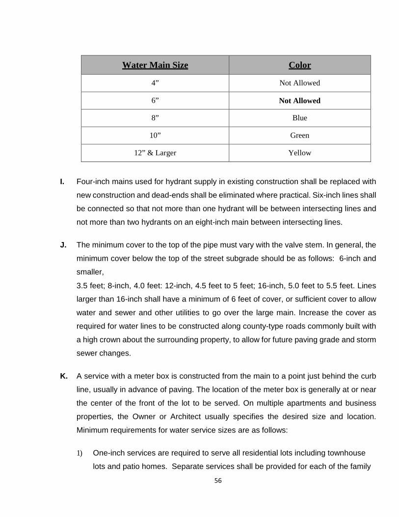
12) Fire hydrant bonnet shall be painted according to the size of the main to which it is
attached. See chart on following page. The remainder of the hydrant above ground shall be painted aluminum.
56
Water Main Size Color
4” Not Allowed
6” Not Allowed
8” Blue
10” Green
12” & Larger Yellow
I. Four-inch mains used for hydrant supply in existing construction shall be replaced with
new construction and dead-ends shall be eliminated where practical. Six-inch lines shall
be connected so that not more than one hydrant will be between intersecting lines and
not more than two hydrants on an eight-inch main between intersecting lines.
J. The minimum cover to the top of the pipe must vary with the valve stem. In general, the
minimum cover below the top of the street subgrade should be as follows: 6-inch and
smaller,
3.5 feet; 8-inch, 4.0 feet: 12-inch, 4.5 feet to 5 feet; 16-inch, 5.0 feet to 5.5 feet. Lines
larger than 16-inch shall have a minimum of 6 feet of cover, or sufficient cover to allow
water and sewer and other utilities to go over the large main. Increase the cover as
required for water lines to be constructed along county-type roads commonly built with
a high crown about the surrounding property, to allow for future paving grade and storm
sewer changes.
K. A service with a meter box is constructed from the main to a point just behind the curb
line, usually in advance of paving. The location of the meter box is generally at or near
the center of the front of the lot to be served. On multiple apartments and business
properties, the Owner or Architect usually specifies the desired size and location.
Minimum requirements for water service sizes are as follows:
1) One-inch services are required to serve all residential lots including townhouse
lots and patio homes. Separate services shall be provided for each of the family
57
units.
2) The size of apartment, condominium, or multi-family services will depend on the
number of units served with a minimum of one meter per building.
3) Fittings shall include mega-lugs and shall be polywrapped.
L. A domestic service connection shall not be allowed on fire hydrant leads except by special permission from the Director of Public Works & Engineering or his/her designee.
M. No meter boxes will be allowed in paved surfaces.
58
Section 2.2
Sanitary Sewer
A. Sizes and grades for sanitary sewer lines shall be based on serving the proposed
development and all upstream areas in the drainage basin at full development. The minimum size for sanitary sewer mains shall be 8-inches. Design calculations for sizing lines shall be included in the plans, along with drainage area map. If feasible, sewers shall be placed in streets or as shown in the City Standard Construction Details. Sewers are usually located in the center of residential streets. Each addition has its challenges, therefore, no fixed rules will apply to all cases regarding the location of sanitary sewers.
B. Minimum cover shall be 3.5 feet; exceptions authorized by the Director of Public Works & Engineering or his/her designee shall have concrete protection. In general, the minimum depth for sewer to serve given property with a 4-inch lateral shall be 3-feet plus 2% times the length of the house lateral (the distance from the sewer to the center of the house). Thus, for a house 135 feet from the sewer, the depth would be 3-feet plus 2% x 135 feet = 3.0 plus 2.7 = 5.7 feet. The depth of the flow line of the sewer should then be at least 5.7 feet below the elevation of the ground at the point where the service enters the house. Profiles of the ground line 20-feet past the building line will be required to verify that this criterion is met. On lines deeper than 12 feet, a parallel sewer line will be required when laterals are to be attached. This requirement should be discussed with the Director of Public Works & Engineering.
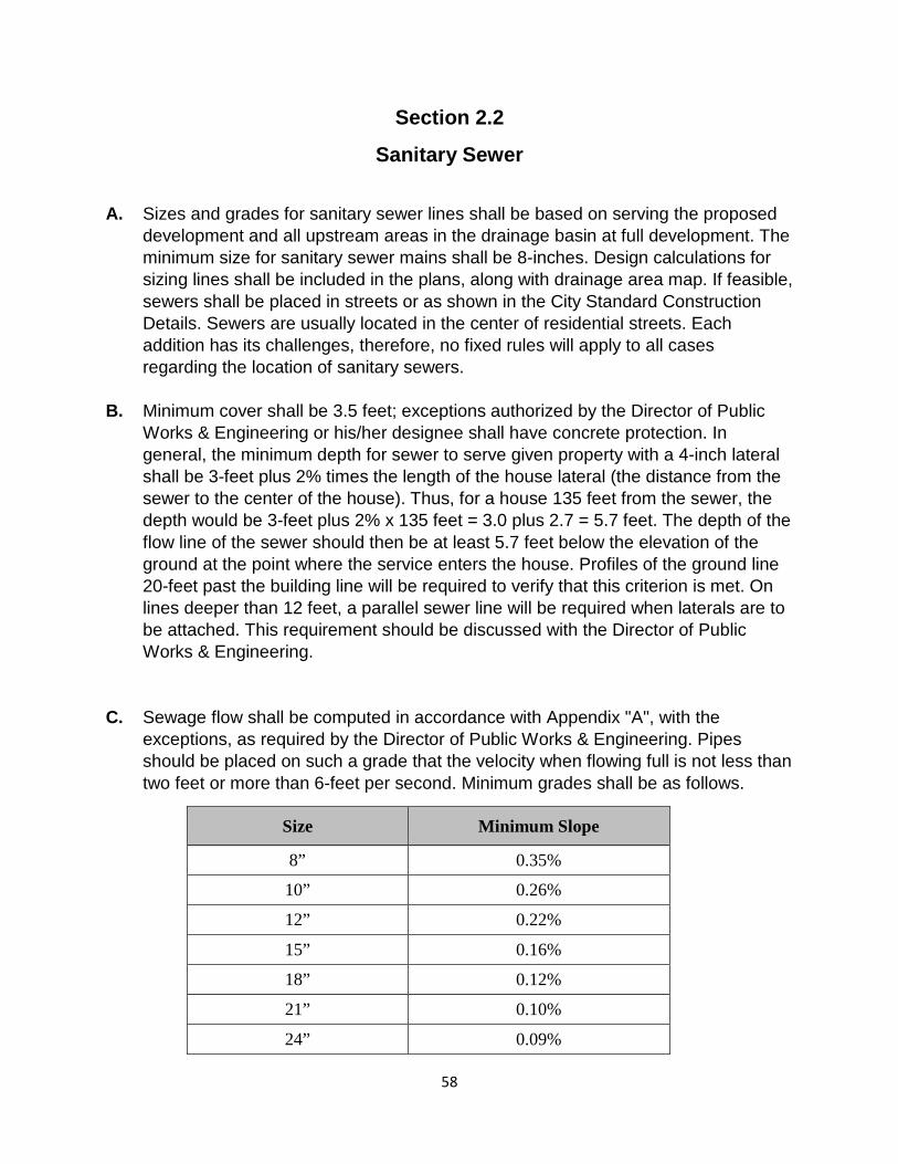
C. Sewage flow shall be computed in accordance with Appendix "A", with the exceptions, as required by the Director of Public Works & Engineering. Pipes should be placed on such a grade that the velocity when flowing full is not less than two feet or more than 6-feet per second. Minimum grades shall be as follows.
Size Minimum Slope
8” 0.35%
10” 0.26%
12” 0.22%
15” 0.16%
18” 0.12%
21” 0.10%
24” 0.09%

59
D. All grades shall be shown to the nearest 0.01%. Grades shall be evenly divisible by 4, and if practical, they should be even, such as: 0.20%, 0.40%, 0.60%, and 1.00%, etc., in order to facilitate field computations. When the slope of a sewer changes, a manhole will be required. No vertical curves will be allowed. Horizontal curves (pulling pipe not joints) with a minimum 200 foot Radius to match change in street direction will be allowed as approved by the Director of Public Works & Engineering, but will not be allowed across residential single family and duplex lots.
E. The sizes and locations of manholes, wyes, bends, tap connections, cleanouts, etc., shall be approved by the Director of Public Works & Engineering. In general, manholes shall be placed at all four-way connections and three-way connections. The diameter of a manhole constructed over the center of a sewer should vary with the size of the sewer. For 6", 8", and 10" sewers, the manhole shall be 4.0-foot minimum diameter; for 12", 15", 18", 21", 24" and 27" - 5.0 foot minimum diameter; 30" and 36" - 6-foot minimum diameter. In Flood Plains, sealed manholes with appropriate venting are to be used to prevent the entrance of storm water. Manholes in flood plains shall be vented as required by TNRCC. Manholes shall be placed on the ends of all lines. Drop manholes shall be required when the inflow elevation is more than 18-inches above the outflow elevation. Construct manholes at each end of lines that are installed by other than open cut and at each end of aerial crossing lines. Sewer mains and water mains shall be not less than nine feet apart as measured from outside to outside of pipe and shall meet all Texas Natural Resource Conservation Commission requirements.
F. Laterals- The sizes and locations of laterals shall be as approved by the Director of Public Works & Engineering. In general, for single family dwellings, the lateral size shall be 4" minimum; for multiple units, apartments, local retail and commercial - 6" minimum; for manufacturing and industrial, the size should be 8" or larger as required. House laterals usually come out 10 feet downstream from the center of the lot and shall have a 10-foot lateral separation from the water service. Manholes will be required on 6-inch and larger laterals where they connect to the main line. Laterals will not be attached to sewer mains that are deeper than 12 feet except by special permission from the Director of Public Works & Engineering or his/her designee. A minimum of one lateral per building shall be required. Also, a minimum of one lateral per residential lot shall be required. Duplexes shall have two laterals.
G. Railroad, State Highway and creek crossings, etc., shall be as approved by the Director of Public Works & Engineering or his/her designee. The developer is responsible for obtaining permits from the Railroad Company and from the Texas Department of Transportation and for ensuring that construction meets all the permit requirements.
60
H. The developer’s Engineer shall furnish all line and grade stakes for construction. All property lines and corners must be properly staked to insure correct alignment. Monuments must be set at the corners of the property as shown in the Standard Construction Details. The City will not be liable for improper alignment or delay of any kind caused by improper or inadequate surveys by the developer or by interference of other utilities.
I. In order to provide access for sewer lines for cleaning, manholes shall be so located that 250 feet of sewer rod can reach any point in the line. This means that manhole spacing shall be a maximum of 500 feet.
J. No sewer line shall be located nearer than five feet from any tree or structure.
K. No sanitary sewer in alleys unless approved by the Director of Public Works & Engineering.
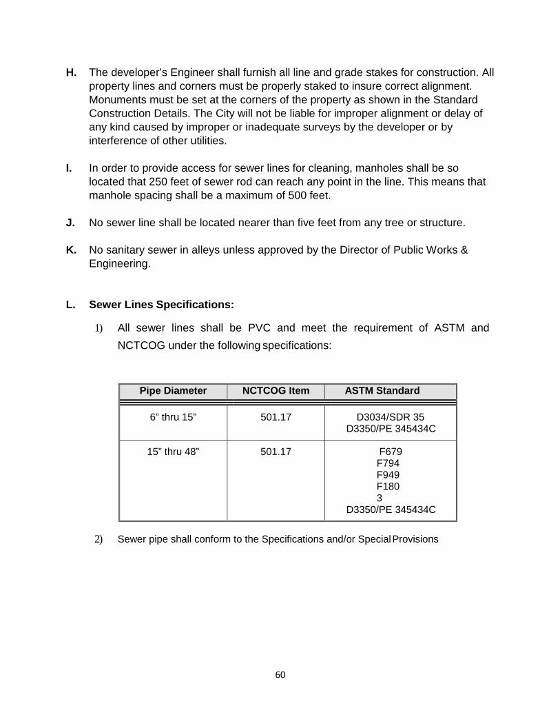
L. Sewer Lines Specifications:
1) All sewer lines shall be PVC and meet the requirement of ASTM and NCTCOG under the following specifications:
Pipe Diameter NCTCOG Item ASTM Standard
6” thru 15” 501.17 D3034/SDR 35 D3350/PE 345434C
15” thru 48” 501.17 F679 F794 F949 F1803
D3350/PE 345434C
2) Sewer pipe shall conform to the Specifications and/or Special Provisions

61
M. Lift Stations (Shall be only as approved by the Director of Public Works & Engineering or His/her designee)
1) Lift station design shall be in full conformance to TNRCC Regulations, latest revision.
Letter approval from the TNRCC must be provided at time of Preliminary Engineering
plan submittal. Flows shall be as calculated by this manual.
2) Lift stations with peak flows under 1.4 MGD shall utilize submersible pumps as
manufactured by Flygt Corporation or approved equal.
3) The current rules can be
obtained at:
www.tceq.state.tx.us
62
Section 2.3
Form of Plans A. Plans shall be clear, legible, and neatly drawn on bordered sheets, full size shall be
24” x 36”, half size on 12” x 18” sheets. Each sheet shall clearly display the Texas Professional Engineer's seal of the Engineer under whose direction the plans were designed. A title block in the lower right-hand corner shall be filled in to include: (l) project name; (2) Engineer's name, address, and telephone number.
B. The plan sheet should generally be drawn so that the north arrow points to the top or to the right side of the sheet. It is important that the plan show sufficient surrounding streets, lots, and property lines so the existing water and sewer may be adequately shown and so that proper consideration may be given to future extensions. Proposed water and sewer lines shall be stubbed out to the addition extremities in order that future extensions may be made with a minimum of inconvenience. Unless it would make the plan very difficult to read, both water and sewer lines should be shown on the same sheet. The lines on the profile sheet shall be drawn in the same direction as on the plan. Lettering shall be oriented to be read upward or from left to right.
C. On large additions or layouts requiring the use of more than six sheets (total of plan & profile), key sheets may be required on a scale of 1" = 400' or 1" = 1000', as designated by the Director of Public Works & Engineering. They shall show the overall layout with the specific project clearly indicated with reference to individual sheets.
D. The use of "off-standard" scales will not be permitted. A plan shall be drawn to scales of 1" = 20', or 1" = 40'. Plans for water and sewer that do not involve great detail should be drawn on a scale of 1" = 50' or 1” = 60’. Plans in and along creeks, heavily wooded sections, streets with numerous utilities, or as may be required to produce a clean and legible drawing, shall be drawn on plan-profile sheets or separate plan and profile sheets on a scale 1" = 40'. If the plan is in an extremely congested area, a scale of 1" = 20' may be necessary. All profiles shall be drawn on a vertical scale (1” = 4’) as required for clarity, and the horizontal scale shall be the same as for the plan unless otherwise directed by the Director of Public Works & Engineering.

63
Section 2.5
Data to be Included in Plans
A. Sewer Data to be included on Plan Sheet: The plan shall show the existing and proposed water and sewer lines and all appurtenances thereto. The plan should also have the storm sewer system dashed in. All lines shall be numbered, lettered or otherwise designated on both plan and profile sheets. All lines shall show sizes and direction of flow on both the plan and profile sheets. Stationing shall be shown to the nearest 0.1 foot and each new line shall begin at 0+00 at the outlet and increase up the sewer. Station pluses at all junctions of sewers, horizontal P.C.'s, and P.T.'s, bends, angle points, wyes, manholes, the centerlines of all cross streets and railroads, and all crossing utilities, etc., shall be shown on both plan and profile. The degree of angles and horizontal curve data shall be shown on the plan only. Minimum Radius for sanitary sewer mains is 200 feet by pulling pipe not joints. Sewer laterals shall be shown at a location most convenient to serve the property.
Sewer laterals will usually be near the center of the lot, either at the street or alley. If the lateral is to be adjacent to the water service, then show the lateral 10 feet downstream. The location shall be designated on the plans.
B. Sewer Data to be included on the Profile Sheet: The data for the profile sheet shall be obtained by running a line of levels along the actual route and by taking any other necessary observations. Profiles shall show the elevations to the nearest 0.1 foot of the ground at the centerline of the sewer, and to the right and left of the centerline of the sewer at the location of the approximate center of the proposed houses or buildings to be served, and the approved street or alley grade. Profiles shall also show the sewer pipe, manholes, etc. The size of the sewer, the direction of the flow, and the grade to the nearest 0.01% shall be indicated just over the "pipe" and the total linear footage of line, size, kind of pipe, and type of embedment or encasement shown below the "pipe". The design flow, pipe capacity and velocity must be shown in the profile. All of the information pertaining to the horizontal data, station pluses, appurtenances to be built, etc., is usually shown just above the ground line, whereas, the flow line (invert) elevations are shown below the pipe. Elevations of crossing and parallel utilities shall be shown. All invert elevations shall be shown to the nearest 0.01-foot. Invert elevations shall be recorded at all junctions (all lines-in and out), at grade breaks, the ends of lines, or other points as requested by the Director of Public Works & Engineering. City Benchmarks used shall also be clearly shown, giving the descriptive locations and elevations. Elevations must be from sea level datum, not assumed. Bench level circuits should begin at a City of Sachse Control monument and benchmark of second order accuracy established at least every one-half mile through the project. All existing water, sewer, gas, storm sewer, telephone, power, and other utilities parallel to or crossing the
64
proposed sewer or water line shall be adequately designated as to size, type, and location.
C. Data to be included for Water Plan and Profile: Indicate the location of any existing valves required for shutdown purposes and of any tees, ends, etc., to be tied into. Indicate clearly the sizes of the lines to be installed, and all proposed valves, fire hydrants, tees, bends, reducers, plugs, sleeves, wet connections, tap connections, creek, railroad or highway crossings, tunnels, meter boxes, valve vaults, and other appurtenances at each intersection or as required. Where the pipe is to be laid around a curve, the curve data must be provided. The size and type of services and the material, type of joint, and class of pipe may be indicated by adequate notation in the lower left or right hand corners of the plan sheet. Water services and meter boxes shall be indicated and shall be located at or near the center of the front of each lot. Waterline profiles are required on lines 12-inches and larger, follow the general procedures as outlined for sewers, except that the grades and elevations of the proposed water line usually need not be shown closer than the nearest 0.1-foot except at P.V.I.’s where the elevation shall be shown to the nearest 0.01-foot for field calculation purposes.

65
APPENDIX “A”
Sanitary Sewer Daily Flow Calculations
Apartment Sanitary Sewer Flow
95 gal. x .75 = 71.25 gal. per day per person 22 units per acre with 3 persons per unit Calculations (71.25) (22) (3) = 4,702 or 4,700 gallons per day per acre.
Office Sanitary Sewer Flow
3100 parking spaces for 34.7 acres One person per parking space 20 gallons per person per day 3100 = 89.33 persons per acre (20 gal) = 1,786.7 or 1,790 gal. per day per acre. 34.7 acres
Residential Sanitary Sewer Flow
95 gallons per person per day 4 units per acre 3.5 persons per unit (95) (4) (3.5) = 1330 gallons per acre per day
Nursing Home Sanitary Sewer Flow
150 beds -heritage Manor 90 gallons per day per bed 90 x 150 = 13,500 gallons per day
Patio Home Sanitary Sewer Flow
95 gallons per person per day 10 units per acre 3.5 persons per unit (95) (10) (3.5) = 3,325 gallons per day/acre
Add 500 gallon per acre per day for inflow and infiltration. Peaking factor shall be applied to daily flow calculations but not to inflow and infiltration. Peak factors shall be in accordance with ASCE Manual and Reports on Engineering Practice No. 60/WPCF Manual of Practice No. FD-5. Generally the following factors applies:
Acres Peaking Factor 0 – 65 ................................................................... 5 70 ...................................................................... 4.9 80 ...................................................................... 4.8 85 .................................................................... 4.78 90 .................................................................... 4.72 100 .................................................................. 4.66 110 .................................................................. 4.62 120 .................................................................. 4.50 130 .................................................................. 4.35 140 .................................................................. 4.25 150 .................................................................. 4.20

66
City of Sachse, Texas
Drainage Design
67
Section 3.1
Stormwater General A. Introduction
Storm water runoff is that portion of the precipitation that flows over the ground surface during and for a period after a storm. The objective of designing storm sewer systems is to convey runoff in a functional and efficient way from places it is not wanted to the nearest acceptable discharge point. This transfer of runoff is done in sufficient time and methods to avoid damage and unacceptable amounts of inconvenience to the general public. Prior to the design of a storm drainage system, an overall drainage plan shall be submitted to the City for review as a part of the Preliminary Plat submittal. Upon approval of the preliminary plat by the City, the actual construction plans can be designed.
This manual provides guidelines for design of storm drainage facilities in the City of Sachse. The procedures outlined herein shall be followed for all drainage design and review of plans submitted to the City.
68
Section 3.2
Drainage Design Theory A. Drainage Area Determination and System Designation
The size and shape of each drainage area and sub-area must be determined for each storm drainage facility. This size and shape should be determined from topographic maps at scale of 1 inch = 200 feet or less. Where the contour interval is insufficient or physical conditions may have changed from those shown on existing maps, it may be necessary to supplement the maps with field topographic surveys. The actual conditions should always be verified by a reconnaissance survey. In preparing the drainage area maps, careful attention must be given to the gutter configurations at street intersections. The direction of flow in the gutters should be shown on the maps and on the construction plans. The performance of these surveys is the responsibility of the Engineer designing the drainage facility.
B. Rainfall FIGURE 1, which shows anticipated rainfall rates for storm durations from 5 minutes to 6 hours, has been prepared utilizing the information contained in the U. S. Department of Commerce, Weather Bureau, HYDRO-35 (National Technical Information Service Publication No. PB272-112, dated June, 1977). Interpolation of rainfall rates versus durations from the isopluvial maps contained in HYDRO-35 were used to prepare FIGURE 1 for durations less than 60 minutes. For durations beyond 60 minutes the information shown in FIGURE 1 was derived from Weather Bureau Technical Paper No. 40, dated May, 1961.
C. Design Storm Frequency The individual curves shown on FIGURE 1 labeled "5 Yr.", "10 Yr.", "25 Yr.", "50 Yr.", and "100 Yr." are referred to as "Design Storm Frequency". The term "100-year storm" does not mean that a storm of that severity can be expected once in any 100-year period, but rather that a storm of that severity has a one in one hundred chance of occurring in any given calendar year. Each storm drainage facility shall be designed to convey the runoff which results from the 100-year design storm as shown in Section III, CRITERIA AND DESIGN PROCEDURES.
69
D. Determination of Design Discharge Prior to hydraulic design of drainage facilities the amount of runoff from the particular drainage area must be determined. The Rational, the Unit Hydrograph, and the HEC-I Computer Program are the accepted methods, for computing volumes of storm water runoff. Data from the Flood Insurance Study shall be used in lieu of Rational Method, Unit Hydrograph or HEC-I for determination of drainage and floodway easement elevations and design discharge flows, if such data is available. However, all discharge values shall be based on full development of the drainage basin as outlined on the current zoning maps available from the City. In the event that the Flood Insurance Study is not based on current zoning, the study should be reanalyzed, revised and submitted to FEMA for acceptance. In the event that the revised study indicates a water surface is less than that shown on the Flood Insurance study the higher value shall be used if the study is not submitted to FEMA.
E. Rational Method The use of the Rational Method, introduced in 1889, is based on the following assumptions: a) The peak rate of runoff at any point is a direct function of the average rainfall intensity during the time of concentration to that point. b) The frequency of the peak discharge is the same as the frequency of the average rainfall intensity. c) The time of concentration is the time required for the runoff to become established and flow from the most remote part of the drainage area to the design point. The Rational Method is based on the direct relationship between rainfall and runoff expressed in the following equation: Q = C I A, where
• “Q” is the storm flow at a given point in cubic feet per second (c.f.s.). • “C” is a coefficient of runoff representing the ratio of runoff to rainfall.
• “I” is the average intensity of rainfall in inches per hour for a period equal to the
time of flow from the farthest point of the drainage area to the point of design and is obtained from FIGURE 1.
• “A” is the area in acres that is tributary to the point of design.
The determination of the factors, runoff coefficient and time of concentration shown in this manual have been developed through past experience in the City's system and by review of values recommended by others. The time of concentration has been adopted from the Texas Department of Transportation Hydraulic Design Manual, revised March 2004.
70
F. Runoff Coefficient The runoff coefficient "C" in the Rational Formula is dependent on the character of the soil and the degree and type of development in the drainage area. The nature and condition of the soil determine its ability to absorb precipitation. The absorption ability generally decreases as the duration of the rainfall increases until saturation occurs. Infiltration rates in the Sachse area generally are low due to the cohesive soils. As a drainage area develops the amount of runoff increases generally in proportion to the amount of impervious areas such as streets, parking areas and buildings.
G. Time of Concentration The time of concentration is defined as the longest time that will be required for water to flow from the upper limit of a drainage area to the point of concentration, without interruption of flow by detention devices. This time is a combination of the inlet time, which is the time for water to flow over the surface of the ground from the upper limit of the drainage area to the first storm sewer inlet, and the flow time in the conduit or channel to the point of concentration. The flow time in the conduit or channel is computed by dividing the length of the conduit by the average velocity in the conduit. (Note: When accumulating times, base the time of concentration on the actual calculated time of concentration at the initial point of interception, even if it is less than the minimum time of concentration. For the design of the storm sewer use the minimum time of concentration as shown in TABLE 1 until such time that the actual time of concentration exceeds the minimum time. Although the basic principles of the Rational Method are applicable to all sizes of drainage areas, natural retention of flow and other interruptions cause an attenuation of the runoff hydrograph resulting in over-estimation of rates of flow for larger areas. For this reason, in development of runoff rates in larger drainage areas, use of the Unit Hydrograph Method is recommended.
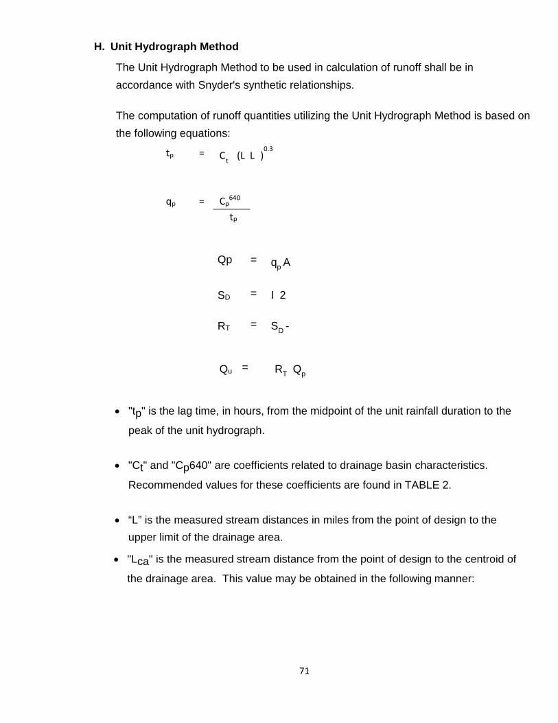
71
t
H. Unit Hydrograph Method
The Unit Hydrograph Method to be used in calculation of runoff shall be in accordance with Snyder's synthetic relationships.
The computation of runoff quantities utilizing the Unit Hydrograph Method is based on the following equations:
tp = C (L L )0.3
qp = Cp
640
tp
Qp = qp A
SD = I 2
RT = SD -
Qu = RT Qp
• "tp" is the lag time, in hours, from the midpoint of the unit rainfall duration to the
peak of the unit hydrograph.
• "Ct" and "Cp640" are coefficients related to drainage basin characteristics.
Recommended values for these coefficients are found in TABLE 2.
• “L” is the measured stream distances in miles from the point of design to the
upper limit of the drainage area.
• "Lca" is the measured stream distance from the point of design to the centroid of
the drainage area. This value may be obtained in the following manner:
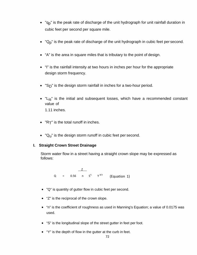
72
• "qp" is the peak rate of discharge of the unit hydrograph for unit rainfall duration in
cubic feet per second per square mile.
• "Qp" is the peak rate of discharge of the unit hydrograph in cubic feet per second.
• “A” is the area in square miles that is tributary to the point of design.
• “I” is the rainfall intensity at two hours in inches per hour for the appropriate
design storm frequency.
• "SD" is the design storm rainfall in inches for a two-hour period.
• "Lis" is the initial and subsequent losses, which have a recommended constant
value of 1.11 inches.
• "RT" is the total runoff in inches.
• "Qu" is the design storm runoff in cubic feet per second.
I. Straight Crown Street Drainage
Storm water flow in a street having a straight crown slope may be expressed as follows:
Z
Q = 0.56 n S½ Y 8/3 (Equation 1)
• “Q” is quantity of gutter flow in cubic feet per second.
• “Z” is the reciprocal of the crown slope.
• “n” is the coefficient of roughness as used in Manning's Equation; a value of 0.0175 was used.
• “S” is the longitudinal slope of the street gutter in feet per foot.
• “Y” is the depth of flow in the gutter at the curb in feet.
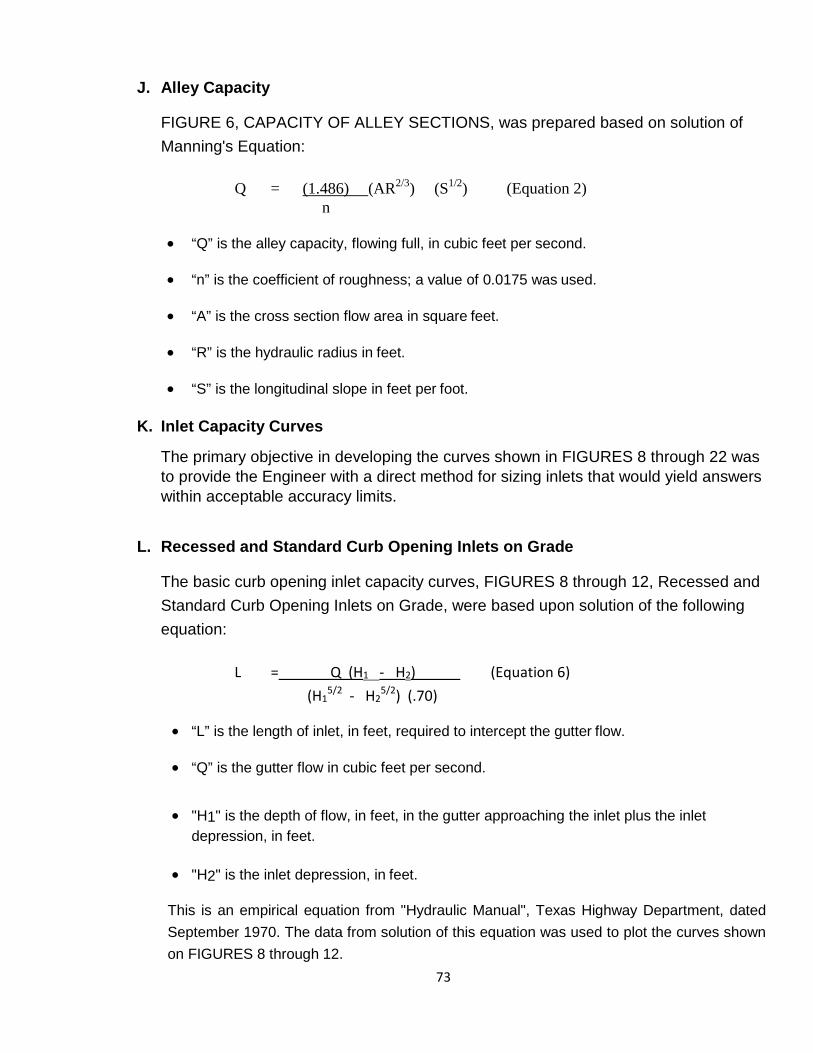
73
J. Alley Capacity
FIGURE 6, CAPACITY OF ALLEY SECTIONS, was prepared based on solution of Manning's Equation:
Q = (1.486) (AR2/3) (S1/2) (Equation 2)
n
• “Q” is the alley capacity, flowing full, in cubic feet per second.
• “n” is the coefficient of roughness; a value of 0.0175 was used.
• “A” is the cross section flow area in square feet.
• “R” is the hydraulic radius in feet.
• “S” is the longitudinal slope in feet per foot.
K. Inlet Capacity Curves
The primary objective in developing the curves shown in FIGURES 8 through 22 was to provide the Engineer with a direct method for sizing inlets that would yield answers within acceptable accuracy limits.
L. Recessed and Standard Curb Opening Inlets on Grade
The basic curb opening inlet capacity curves, FIGURES 8 through 12, Recessed and Standard Curb Opening Inlets on Grade, were based upon solution of the following equation:
L = Q (H1 - H2) (Equation 6)
(H15/2 - H2
5/2) (.70)
• “L” is the length of inlet, in feet, required to intercept the gutter flow.
• “Q” is the gutter flow in cubic feet per second.
• "H1" is the depth of flow, in feet, in the gutter approaching the inlet plus the inlet depression, in feet.
• "H2" is the inlet depression, in feet.
This is an empirical equation from "Hydraulic Manual", Texas Highway Department, dated September 1970. The data from solution of this equation was used to plot the curves shown on FIGURES 8 through 12.
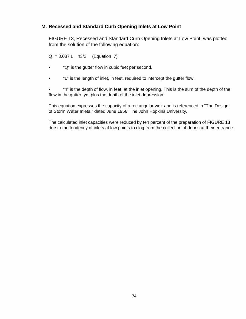
74
M. Recessed and Standard Curb Opening Inlets at Low Point
FIGURE 13, Recessed and Standard Curb Opening Inlets at Low Point, was plotted from the solution of the following equation: Q = 3.087 L h3/2 (Equation 7) • “Q” is the gutter flow in cubic feet per second. • “L” is the length of inlet, in feet, required to intercept the gutter flow. • “h” is the depth of flow, in feet, at the inlet opening. This is the sum of the depth of the flow in the gutter, yo, plus the depth of the inlet depression. This equation expresses the capacity of a rectangular weir and is referenced in "The Design of Storm Water Inlets," dated June 1956, The John Hopkins University. The calculated inlet capacities were reduced by ten percent of the preparation of FIGURE 13 due to the tendency of inlets at low points to clog from the collection of debris at their entrance.

75
N. Hydraulic Designs of Closed Conduits
All closed conduits shall be hydraulically designed through the application of Manning's Equation expressed as follows:
Q = A V
Q = 1.486 AR2/3 Sf1/2
n
R = A P
• “Q” is the flow in cubic feet per second.
• “A” is the cross sectional area of the conduit in square feet.
• “V” is the velocity of flow in the conduit in feet per second.
• “n” is the roughness coefficient of the conduit.
• “R” is the hydraulic radius, which is the area (“A”) of flow divided by the wetted perimeter
(“P”).
• "Sf" is the friction slope of the conduit in feet per foot.
• “P” is the wetted perimeter.
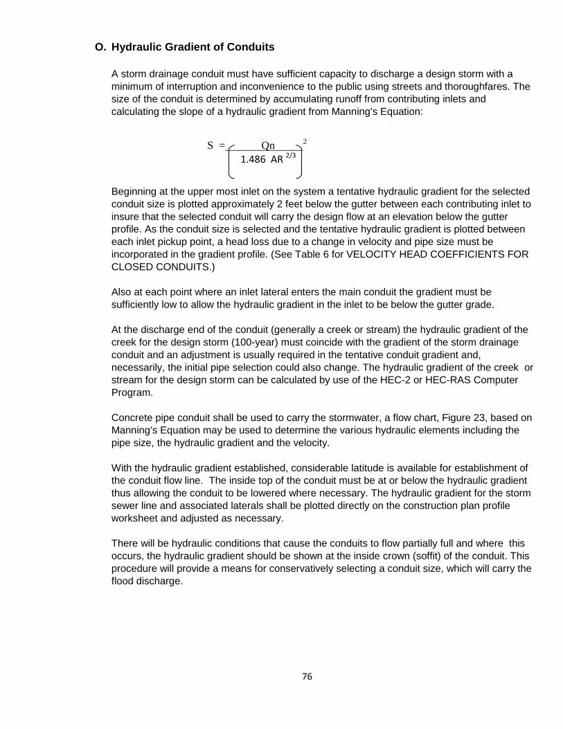
76
O. Hydraulic Gradient of Conduits A storm drainage conduit must have sufficient capacity to discharge a design storm with a minimum of interruption and inconvenience to the public using streets and thoroughfares. The size of the conduit is determined by accumulating runoff from contributing inlets and calculating the slope of a hydraulic gradient from Manning's Equation:
S = Qn 2
1.486 AR 2/3
Beginning at the upper most inlet on the system a tentative hydraulic gradient for the selected conduit size is plotted approximately 2 feet below the gutter between each contributing inlet to insure that the selected conduit will carry the design flow at an elevation below the gutter profile. As the conduit size is selected and the tentative hydraulic gradient is plotted between each inlet pickup point, a head loss due to a change in velocity and pipe size must be incorporated in the gradient profile. (See Table 6 for VELOCITY HEAD COEFFICIENTS FOR CLOSED CONDUITS.) Also at each point where an inlet lateral enters the main conduit the gradient must be sufficiently low to allow the hydraulic gradient in the inlet to be below the gutter grade. At the discharge end of the conduit (generally a creek or stream) the hydraulic gradient of the creek for the design storm (100-year) must coincide with the gradient of the storm drainage conduit and an adjustment is usually required in the tentative conduit gradient and, necessarily, the initial pipe selection could also change. The hydraulic gradient of the creek or stream for the design storm can be calculated by use of the HEC-2 or HEC-RAS Computer Program. Concrete pipe conduit shall be used to carry the stormwater, a flow chart, Figure 23, based on Manning's Equation may be used to determine the various hydraulic elements including the pipe size, the hydraulic gradient and the velocity. With the hydraulic gradient established, considerable latitude is available for establishment of the conduit flow line. The inside top of the conduit must be at or below the hydraulic gradient thus allowing the conduit to be lowered where necessary. The hydraulic gradient for the storm sewer line and associated laterals shall be plotted directly on the construction plan profile worksheet and adjusted as necessary. There will be hydraulic conditions that cause the conduits to flow partially full and where this occurs, the hydraulic gradient should be shown at the inside crown (soffit) of the conduit. This procedure will provide a means for conservatively selecting a conduit size, which will carry the flood discharge.
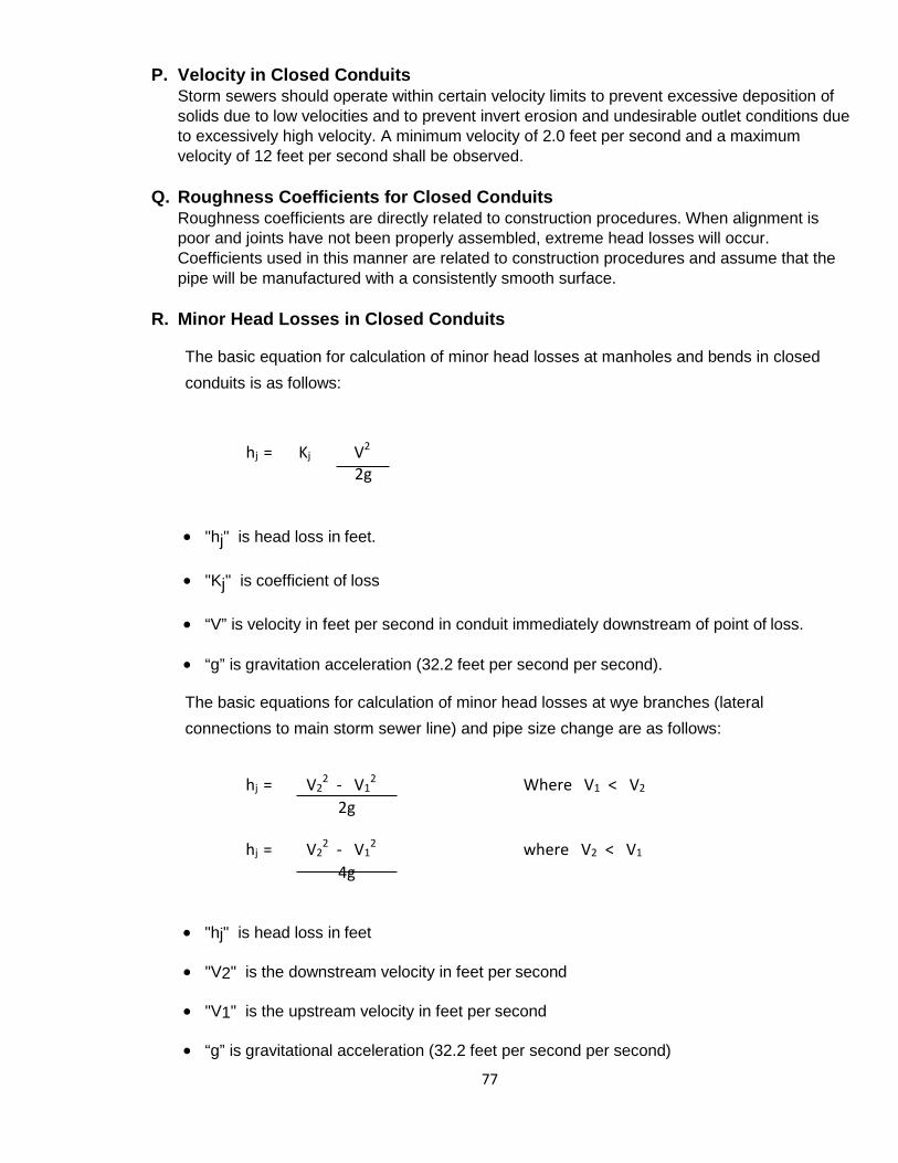
77
P. Velocity in Closed Conduits Storm sewers should operate within certain velocity limits to prevent excessive deposition of solids due to low velocities and to prevent invert erosion and undesirable outlet conditions due to excessively high velocity. A minimum velocity of 2.0 feet per second and a maximum velocity of 12 feet per second shall be observed.
Q. Roughness Coefficients for Closed Conduits Roughness coefficients are directly related to construction procedures. When alignment is poor and joints have not been properly assembled, extreme head losses will occur. Coefficients used in this manner are related to construction procedures and assume that the pipe will be manufactured with a consistently smooth surface.
R. Minor Head Losses in Closed Conduits
The basic equation for calculation of minor head losses at manholes and bends in closed conduits is as follows:
hj = Kj V2
2g
• "hj" is head loss in feet.
• "Kj" is coefficient of loss
• “V” is velocity in feet per second in conduit immediately downstream of point of loss.
• “g” is gravitation acceleration (32.2 feet per second per second).
The basic equations for calculation of minor head losses at wye branches (lateral connections to main storm sewer line) and pipe size change are as follows:
hj = V2
2 - V12 Where V1 < V2
2g
hj = V22 - V1
2 where V2 < V1
4g
• "hj" is head loss in feet
• "V2" is the downstream velocity in feet per second
• "V1" is the upstream velocity in feet per second
• “g” is gravitational acceleration (32.2 feet per second per second)
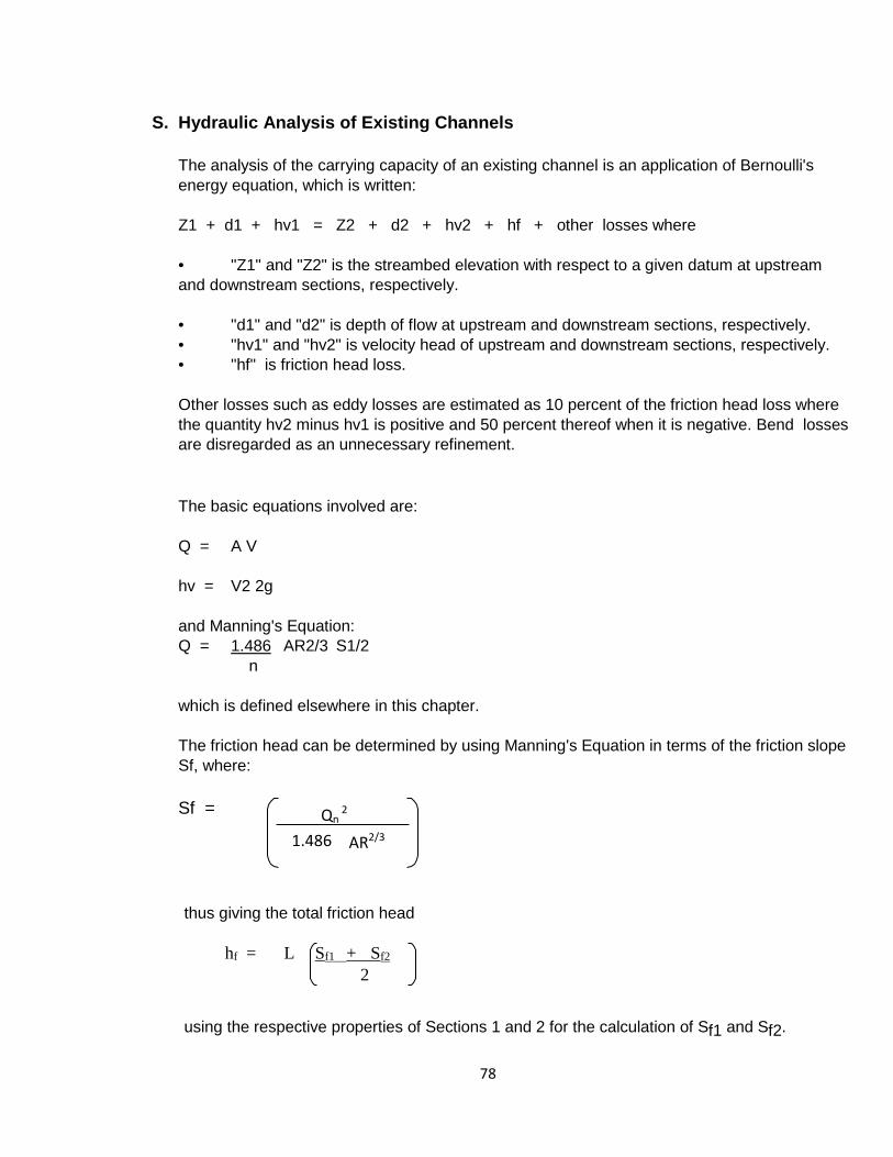
78
S. Hydraulic Analysis of Existing Channels
The analysis of the carrying capacity of an existing channel is an application of Bernoulli's energy equation, which is written: Z1 + d1 + hv1 = Z2 + d2 + hv2 + hf + other losses where • "Z1" and "Z2" is the streambed elevation with respect to a given datum at upstream and downstream sections, respectively. • "d1" and "d2" is depth of flow at upstream and downstream sections, respectively. • "hv1" and "hv2" is velocity head of upstream and downstream sections, respectively. • "hf" is friction head loss. Other losses such as eddy losses are estimated as 10 percent of the friction head loss where the quantity hv2 minus hv1 is positive and 50 percent thereof when it is negative. Bend losses are disregarded as an unnecessary refinement. The basic equations involved are: Q = A V hv = V2 2g and Manning's Equation: Q = 1.486 AR2/3 S1/2
n
which is defined elsewhere in this chapter. The friction head can be determined by using Manning's Equation in terms of the friction slope Sf, where: Sf =
thus giving the total friction head
hf = L Sf1 + Sf2
2
using the respective properties of Sections 1 and 2 for the calculation of Sf1 and Sf2.
Qn 2
1.486 AR2/3
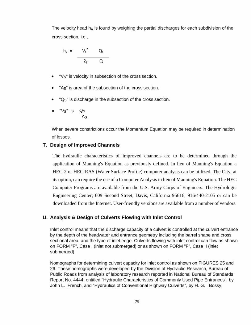
79
The velocity head hv is found by weighing the partial discharges for each subdivision of the
cross section, i.e.,
hv = Vs
2 Qs
2g Q
• "Vs" is velocity in subsection of the cross section.
• "As" is area of the subsection of the cross section.
• "Qs" is discharge in the subsection of the cross section.
• "Vs" is Qs
As
When severe constrictions occur the Momentum Equation may be required in determination
of losses.
T. Design of Improved Channels
The hydraulic characteristics of improved channels are to be determined through the application of Manning's Equation as previously defined. In lieu of Manning's Equation a HEC-2 or HEC-RAS (Water Surface Profile) computer analysis can be utilized. The City, at its option, can require the use of a Computer Analysis in lieu of Manning's Equation. The HEC Computer Programs are available from the U.S. Army Corps of Engineers. The Hydrologic Engineering Center; 609 Second Street, Davis, California 95616, 916/440-2105 or can be downloaded from the Internet. User-friendly versions are available from a number of vendors.
U. Analysis & Design of Culverts Flowing with Inlet Control
Inlet control means that the discharge capacity of a culvert is controlled at the culvert entrance by the depth of the headwater and entrance geometry including the barrel shape and cross sectional area, and the type of inlet edge. Culverts flowing with inlet control can flow as shown on FORM "F", Case I (inlet not submerged) or as shown on FORM "F", Case II (inlet submerged). Nomographs for determining culvert capacity for inlet control as shown on FIGURES 25 and 26. These nomographs were developed by the Division of Hydraulic Research, Bureau of Public Roads from analysis of laboratory research reported in National Bureau of Standards Report No. 4444, entitled "Hydraulic Characteristics of Commonly Used Pipe Entrances", by John L. French, and “Hydraulics of Conventional Highway Culverts", by H. G. Bossy.
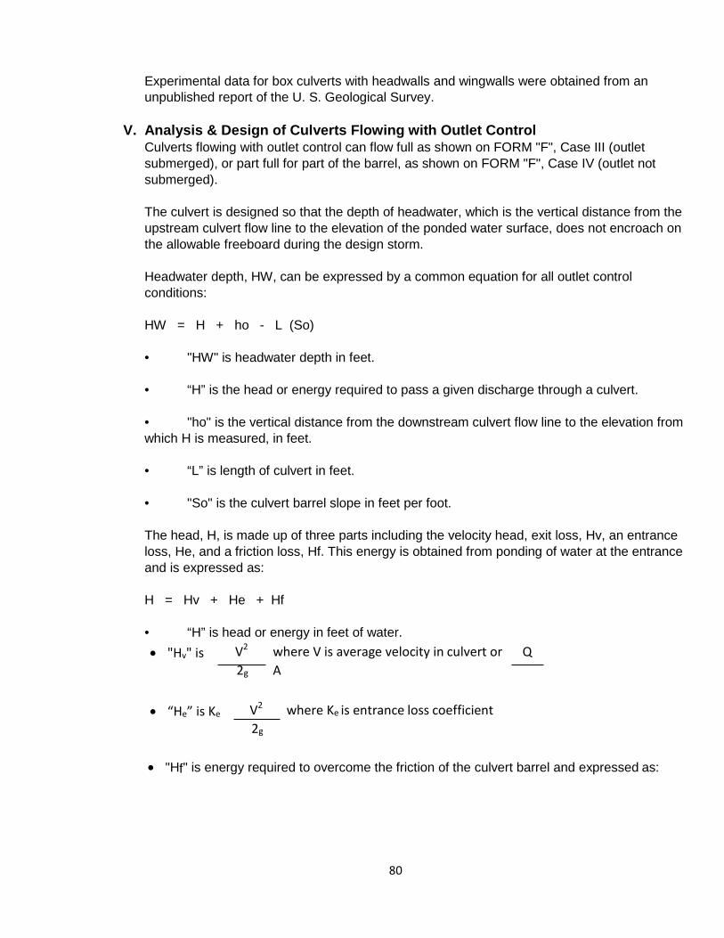
80
Experimental data for box culverts with headwalls and wingwalls were obtained from an unpublished report of the U. S. Geological Survey.
V. Analysis & Design of Culverts Flowing with Outlet Control Culverts flowing with outlet control can flow full as shown on FORM "F", Case III (outlet submerged), or part full for part of the barrel, as shown on FORM "F", Case IV (outlet not submerged). The culvert is designed so that the depth of headwater, which is the vertical distance from the upstream culvert flow line to the elevation of the ponded water surface, does not encroach on the allowable freeboard during the design storm. Headwater depth, HW, can be expressed by a common equation for all outlet control conditions: HW = H + ho - L (So) • "HW" is headwater depth in feet. • “H” is the head or energy required to pass a given discharge through a culvert. • "ho" is the vertical distance from the downstream culvert flow line to the elevation from which H is measured, in feet. • “L” is length of culvert in feet. • "So" is the culvert barrel slope in feet per foot. The head, H, is made up of three parts including the velocity head, exit loss, Hv, an entrance loss, He, and a friction loss, Hf. This energy is obtained from ponding of water at the entrance and is expressed as: H = Hv + He + Hf • “H” is head or energy in feet of water. • "Hv" is V2 where V is average velocity in culvert or Q
2g A
• “He” is Ke V2 where Ke is entrance loss coefficient 2g
• "Hf" is energy required to overcome the friction of the culvert barrel and expressed as:
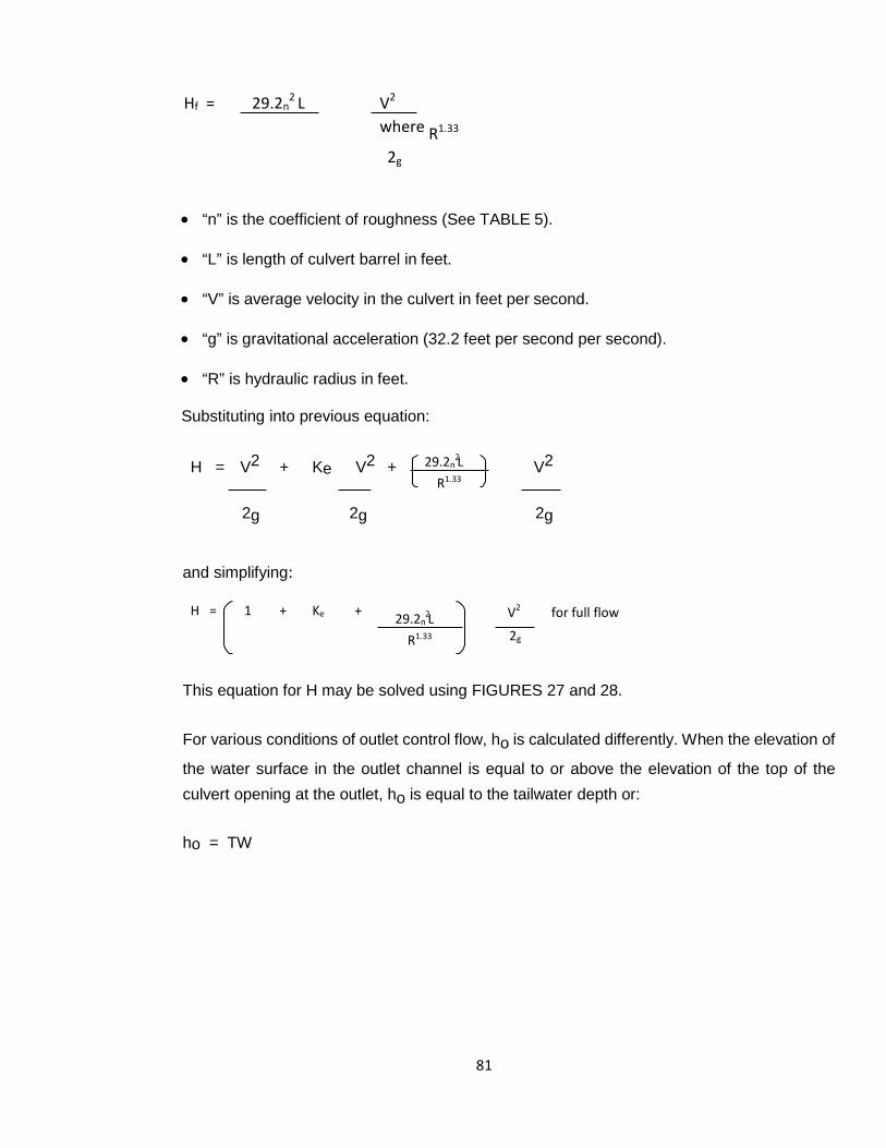
81
29.2n L R1.33
Hf = 29.2n2 L V2
where R1.33
2g
• “n” is the coefficient of roughness (See TABLE 5).
• “L” is length of culvert barrel in feet.
• “V” is average velocity in the culvert in feet per second.
• “g” is gravitational acceleration (32.2 feet per second per second).
• “R” is hydraulic radius in feet.
Substituting into previous equation:
H = V2 + Ke V2 + V2
2g 2g 2g
and simplifying:
H = 1 + Ke + V2 for full flow
2g
This equation for H may be solved using FIGURES 27 and 28.
For various conditions of outlet control flow, ho is calculated differently. When the elevation of
the water surface in the outlet channel is equal to or above the elevation of the top of the culvert opening at the outlet, ho is equal to the tailwater depth or:
ho = TW
29.2n L R1.33
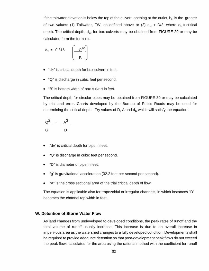
82
If the tailwater elevation is below the top of the culvert opening at the outlet, ho is the greater
of two values: (1) Tailwater, TW, as defined above or (2) dc + D/2 where dc = critical
depth. The critical depth, dc, for box culverts may be obtained from FIGURE 29 or may be
calculated form the formula:
dc = 0.315 Q2/3
B
• “dc” is critical depth for box culvert in feet.
• “Q” is discharge in cubic feet per second.
• “B” is bottom width of box culvert in feet.
The critical depth for circular pipes may be obtained from FIGURE 30 or may be calculated by trial and error. Charts developed by the Bureau of Public Roads may be used for determining the critical depth. Try values of D, A and dc which will satisfy the equation:
Q2 = A3 G D
• “dc” is critical depth for pipe in feet.
• “Q” is discharge in cubic feet per second.
• “D” is diameter of pipe in feet.
• “g” is gravitational acceleration (32.2 feet per second per second).
• “A” is the cross sectional area of the trial critical depth of flow.
The equation is applicable also for trapezoidal or irregular channels, in which instances "D" becomes the channel top width in feet.
W. Detention of Storm Water Flow
As land changes from undeveloped to developed conditions, the peak rates of runoff and the total volume of runoff usually increase. This increase is due to an overall increase in impervious area as the watershed changes to a fully developed condition. Developments shall be required to provide adequate detention so that post-development peak flows do not exceed the peak flows calculated for the area using the rational method with the coefficient for runoff

83
appropriate for the conditions prior to development. The detention system shall be designed for both the 100-yr and 2-yr design storm events.
The criteria for the design of detention facilities are based on the concept that post- development peak flows should not create an adverse condition when compared to pre- development peak flows. In applying such a concept, it is necessary to consider peak flows from a number of different design storms. By considering a range of design storms, it is possible to design an outlet system to limit the discharge from the detention facility and achieve zero or very little increase in flow for a range of storms. Such a design will allow the detention system to achieve maximum effectiveness since both the more frequent and more severe storm events can be controlled.
A form of the Rational Method should be used to calculate inflow volumes from areas less than 50 acres. A form of the inflow hydrographs or unit hydrograph method shall be used for areas of 50 acres or more. No reduction in the design storm frequency shall be considered when utilizing detention systems within the overall storm drainage design.
X. Manholes
Place manholes for cleanout and inspection purposes on all storm sewer lines as shown in the table below.
Pipe Diameter (Inches) Maximum Distance (feet)
12 - 24
350
24 - 36
400
39 - 54
500
=>60
900
84
Section 3.3
General Requirements
A. Design Storm Frequency
Each storm drainage facility, including street capacities, shall be designed to convey the runoff, which results from the 100-year design storm.
Drainage design requirements for open and closed systems shall provide protection for property during a 100-year Design Frequency Storm, with this projected flow carried in the streets and closed drainage systems in accordance with the following:
a) Residential Streets: Based on a transverse slope of a positive ¼” per foot behind
the curb, the 100-year design storm frequency shall not exceed a depth of 1-inch over the top of curb. A maximum flow of 20 cfs will be allowed in each gutter or where gutter capacity is exceeded plus 1-inch. Bypass from upstream inlets shall not exceed 5 cfs through residential street intersections.
b) Collector Streets: Based on parkway slopes of a positive ¼” per foot behind the
curb, the 100-year Design Frequency flows shall not exceed a depth of ½” over the top of curb or where gutter capacity +½” is exceeded. A maximum flow of 20 cfs will be allowed in each gutter or where capacity + ½” gutter is exceeded. Bypass from upstream inlets shall not exceed 5 cfs through collector street inlets.
c) Major Thoroughfares: Based on a transverse slope of a positive ¼” per foot on
the pavement, the 100-year Design Frequency flow shall not exceed the elevation of the lowest top of curb. A maximum of 35 cfs will be allowed in the street or where gutter capacity is exceeded. Bypass from upstream inlets shall be 0 cfs through major thoroughfare intersections.
d) Alleys: The 100-year Design Frequency flows shall not exceed the capacity of the
alley sections shown in FIGURE 6.
e) Excavated Channels: Excavated channels shall have concrete pilot channels if deemed necessary by the Director of Public Works & Engineering, for access or erosion control as outlined below. All excavated channels shall have a design
85
water surface as outlined in 3.06 and be in accordance with FIGURE 24, Type II. Concrete lined channels shall be not less than Type III shown in FIGURE 24.
f) Minimum Lot and Floor Elevations : Minimum lot and floor elevations shall be
established as follows:
i) Lots abutting a natural or excavated channel shall have a minimum elevation for the buildable area of the lot at least at the highest elevation of the drainage floodway easement described in (g) Easements.
ii) Any habitable structure on property abutting a natural or excavated
channel shall have a finished floor elevation at least 2-feet above the 100-year design storm or F.I.A. floodway elevation, whichever is greater.
iii) Where lots do not abut a natural or excavated channel, minimum floor
elevations shall be a minimum of 1-foot above the street curb or edge of alley; whichever is lower, unless otherwise approved by the Director of Public Works & Engineering.
g) Easements: Drainage and floodway easements shall be provided for all open
channels. Drainage and floodway easements for storm sewer pipe shall be the outside diameter of the conduit plus 10-feet with the minimum being 15 feet, and easement width for open or lined channels shall be at least 20 feet wider than the top of the channel, 15 feet of which shall be on one side to serve as an access for maintenance purposes.
h) Positive Overflow: The approved drainage system shall provide for positive
overflow at all Low Points. The term "Positive Overflow" means that when the inlets do not function properly or when the design capacity of the conduit is exceeded the excess flow can be conveyed overland along a paved course. Normally, this would mean along a street or alley but can require the dedication of special drainage easements on private property. Reasonable judgment should be used to limit the easements on private property to a minimum. In specific cases where the chances of substantial flood damages could occur, the City of Sachse may require special investigations and designs by the design engineer.
i) Inlet Design: Inlet spacing shall be in accordance with the design criteria contained
86
in this manual, minimum 300 feet apart, or as required in Section 3.8, maximum length of inlets at one location shall not exceed 20 feet each side of street without prior approval from the Director of Public Works & Engineering.
j) Culverts and Bridges: All drainage structures shall be designed to carry the 100-
year Design Frequency flow. Bridges and culverts shall be designed for a water surface elevation as outlined in 3.6. Two feet of freeboard is required for these structures.
k) Minimum Street or Alley Elevations: Streets or alleys adjacent to an open channel
shall be designed with an elevation not lower than 1-foot above the drainage and floodway easements defined in (g) above or as directed by the Director of Public Works & Engineering.
B. Design Storm Frequency
The Rational Method for computing storm water runoff is to be used for hydraulic design of facilities serving a drainage area of less than 600 acres. For drainage areas of more than 600 acres and less than 1200 acres, the runoff shall be calculated by both the Rational Method and the Unit Hydrograph Method with the larger of the two values being used for hydraulic design. For drainage areas larger than 1200 acres the runoff shall be calculated by the Unit Hydrograph Method, or as outlined in 3.06 (l). In lieu of the Unit Hydrograph Method a HEC-1 (Flood Hydrograph) Computer Analysis can be utilized. The City at its option can require the use of HEC-1 Computer Analysis in lieu of the unit Hydrograph Method. The HEC-1 Computer Program is available from the U.S. Army Corps of Engineers, the Hydrologic Engineering Center, 609 Second Street, Davis, California 95616, 916/440-2105 or can be downloaded from their Internet site. User-friendly versions are available from a number of vendors.

87
C. Flow in Gutters and Inlet Design Unless there are specific agreements to the contrary prior to beginning design of the particular storm drainage project, the City of Sachse requires a storm drain conduit to begin, and consequently the first inlet to be located, at the point where the street gutter flows full based upon the appropriate design storm frequency. If, in the opinion of the Director of Public Works & Engineering, the flow in the gutter would be excessive under these conditions, then direction will be given to extending the storm sewer to a point where the gutter flow can be intercepted by more reasonable inlet locations.
D. Street Intersection Drainage
The use of surface drainage to convey storm water across a street intersection is subject to the following criteria:
a) A major thoroughfare shall not be crossed with surface drainage unless
approved by the Director of Public Works & Engineering.
b) Wherever possible, a collector street shall not be crossed with surface drainage.
c) Wherever possible, a residential street shall not be crossed with surface drainage in excess of 5 cfs.
d) At any intersection, only one street shall be crossed with surface drainage and
this shall be the lower classified street.
E. Procedure for Sizing and Locating Inlets In order that the design procedure for determining inlet locations and sizes may be facilitated, a standard form, INLET DESIGN CALCULATIONS, FORM B, has been included in the Section VIII together with an explanation of how to use the form. Minimum distance between inlets on streets, especially major thoroughfares, shall be 300 feet or as required in Section 3.8. Remainder to be collected offsite before flowing into street.
F. Headwalls and Entrance Conditions Headwalls are used to protect the embankment from erosion and the culvert from displacement. The headwalls, with or without wingwalls and aprons, shall be constructed in accordance with the standard drawings as required by the physical conditions of the particular installation. In general, straight headwalls should be used where the approach velocities in the channel are below 6 feet per second, where headwater pools are formed and where no downstream channel protection is required. Headwalls with wingwalls and aprons should be used where the approach velocities are from 6 to 12 feet per second and downstream channel protection is desirable.
88
Special headwalls and wingwalls may be required where approach velocities are in excess of 12 to 15 feet per second. This requirement varies according to the axis of the approach velocity with respect to the culvert entrance. A table of culvert entrance data is shown on FORM "F". The values of the entrance coefficient, Ke, are a combination of the effects of entrance and approach conditions. It is recognized that all possible conditions may not be tabulated, but an interpolation of values should be possible from the information shown. Where the term "round" entrance edge is used, it means a 6-inch radius on the exposed edge of the entrance.
G. Culvert Discharge Velocities Velocities in culverts should be limited to no more than 15 feet per second, but downstream conditions very likely will impose more stringent controls. Consideration must be given to the effect of high velocities and turbulence on the channel, adjoining property and embankment. TABLE 8 is a tabulation of maximum allowable velocities based on downstream channel conditions.
H. Procedure for Filling in a Flood Plain Fill and development of floodplains, which is not unreasonably damaging to the environment is permitted where it will not create other flood problems. Following are the engineering criteria for fill requested: a) Alterations of the flood plain shall result in no increase in water surface elevation on other properties. No alteration of the channel or adjacent flood plain will be permitted which could result in any degree of increased flooding to other properties, adjacent, upstream, or downstream. Increased flood elevation could cause inundation and damage to areas not presently inundated by the "design flood". The "design flood" for a creek is defined by either the 100-year flood -- the flood having a one percent chance of being equaled or exceeded at least once in any given year -- or the maximum recorded flood, whichever results in the highest peak flood discharges. Streams on the Federal Insurance Rate Maps must be designed using the FIRM 100-year design or the City design, whichever is greater. b) Alterations of the flood plain shall not create an erosive water velocity on or off site. The mean velocity of stream flow at the downstream end of the site after fill shall be no greater than the mean velocity of the stream flow under existing conditions. No alteration to the flood plain will be permitted which would increase velocities of flood waters to the extent that significant erosion of flood plain soils will occur either on the subject property or on other property up or downstream. Soil erosion results in loss of existing vegetation as well as augments destructive sedimentation downstream. Eventual public costs in channel improvements and maintenance (such as removal of debris and dredging of lakes) can be expected as a result. Staff's determination of what constitutes an "erosive" velocity will be based on analysis of the surface material and permissible velocities for specific cross-sections affected by the proposed alteration, using standard engineering tables as a general guide.
89
c) Alterations of the flood plain shall be permitted only to the extent permitted by equal conveyance on both sides of the natural channel. Staff's calculation of the impact of the proposed alteration will be based on the "equal conveyance" principle in order to insure equitable treatment for all property owners. Under equal conveyance, if the City allows a change in the flood carrying capacity (capacity to carry a particular volume of water per unit of time) on one side of the creek due to a proposed alteration of the flood plain, it must also allow an equal change to the owner on the other side. The combined change in flood carrying capacity, due to the proposed alteration plus a corresponding alteration to the other side of the creek, may not cause either an increase in flood elevation or an erosive velocity (Criteria 1 and 2) or violate the other criteria. Conveyance is mathematically expressed as KD = 1.486/n AR 2/3 where n = Manning's friction factor, A = cross sectional area, and R = hydraulic radius. d) The toe of any fill slope shall parallel the natural channel to prevent an unbalancing of stream flow in the altered flood plain. If the alignment of the proposed fill slope departs from the contours of the natural flood plain, the flow characteristics of the floodwaters may be altered, causing possible damaging erosion and deposition in the altered flood plain. If the fill slope flows the natural channel, it will also tend to minimize the visual impact of the alteration. e) To insure maximum accessibility to the flood plain for maintenance and other purposes and to lessen the probability of slope erosion during periods of high water, maximum slopes of filled area shall usually not exceed 4 to 1. Vertical walls, terracing and other slope treatments will be considered only as a part of a landscaping plan submission and if no unbalancing of stream flow results. The purposes of the slope restrictions are to maintain stability and prevent erosion of the slopes, to ease maintenance (e.g. mowing) on the slopes themselves, and to provide accessibility to the areas below the slopes. Being more frequently inundated and therefore subject to greater hazard of erosion, cut slopes must be shallower than fill slopes. f) Landscaping plan submission shall include plans for erosion control of cut and fill slopes, restoration of excavated areas, and tree protection where possible in and below fill area. Landscaping should incorporate natural materials (earth, stone, wood) on cut or fill slopes wherever possible. Applicant should show in plan the general nature and extent of existing vegetation on the tract, and which areas will be preserved, altered, or removed as a result of the proposed alterations. Locations and construction details should be provided showing how trees will be preserved in areas which will be altered by filling or paving within the drip line of those trees. Applicant should also submit plans showing location, type, and size of new plant materials and other landscape features planned for altered flood plain areas. Erosion control plans should demonstrate how the developer intends to minimize soil erosion and sedimentation from his site during and after the fill operation. Plans should include a timing schedule showing anticipated starting and completion dates for each step of the proposed operation. Area and time of exposed soils should be minimized, and existing vegetation should be retained and protected wherever feasible. Disturbed areas should be sodded or covered with mulch and/or temporary vegetation as quickly as possible. Structural measures (e.g. drop structures, sediment
90
ponds, etc.) should be utilized where necessary for effective erosion control, but measures should also minimize structures and materials that detract from the natural appearance of the flood plain.
I. Filling in 100 Year Floodway Fringe a) Definitions i) 100 Year Flood Plain Elevation (100 Year F.P.El.): That water surface
elevation established by applying the Manning Equation (Q = 1.486/n AR 1/2 S 1/2) to the backwater analysis of a stream (river, creek or tributary) using the 100-year storm as the rate of flow (Q). The 100-Year F.P. Elevations are those based on the Corps of Engineer's analysis and form the basis of the Flood Insurance Rate Map (FIRM) as adopted by the Federal Insurance Administration, or subsequent amendments.
ii) Flood Plain: Area of land lying below the 100-year flood plain elevation. iii) Floodway: That central portion of the flood plain which would remain clear of
filling or other obstructions, unless modifications are made within or along the stream bed to offset the effect of additional filling or obstructions within the floodway.
iv) Floodway Fringe: Area between flood plain line and the floodway line that, if
filled, would not produce a significant rise in the 100-year flood plain elevation. v) Significant Rise: A rise in the 100-year water surface elevation greater than
one (1) foot for fill on both sides of a stream or one-half (0.5) feet for fill on one side of a stream.
vi) Floodway Line: The inter-boundary of the floodway fringe determined by
filling within a flood plain along the entire reach of a stream in such a manner that the total cumulative effect of the filling will not create a significant rise in the 100-year water surface elevation.
vii) Equal Conveyance Principle: An area of the cross section of a stream in its
existing condition carrying a percentage of the stream flow, will continue to carry the same percentage of the stream flow after filling in the flood plain occurs without creating a significant rise in the 100-year flood plain elevation.
b) Criteria for Filling in the 100 Year Floodway Fringe
i) Applies only to creeks or portions of creeks with a drainage area of five (5) square miles, or less. ii) Fill and development of the flood plains shall not create a "significant rise" in the 100-year flood plain elevation. iii) For fill and/or other development within the floodway, supporting hydraulic analysis will be required prior to or at the time of submittal of the preliminary plat demonstrating that the proposed development will not create a "significant rise"
91
in the "100-year flood plain elevation". iv) In beginning a backwater analysis for development within a flood plain, the downstream water surface elevation will be determined as follows:
• For fill on one side only of a stream, add one-half (0.5) feet to the 100-year flood plain elevation at the downstream property line.
• For fill on both sides of a stream, add one (1.0) foot to the 100-year flood
plain elevation at the downstream property line. v) Alterations of the floodway shall not create velocities, which could produce maximum erosive velocities in excess of those set forth in Table 7. vi) Floodway Line shall be established in accordance with the definition in (A) above. vii) Equal Conveyance shall be required in accordance with the definition of Equal Conveyance Principle in (A) above. viii) The requirements of 3.36, Paragraphs d, e and f shall apply. ix) Final approval shall be by FEMA.
J. Detention Ponds
On-site detention shall be used to control post-development runoff. Where possible, regional detention systems are highly encouraged. Developments shall be required to provide adequate detention so that post-development peak flows do not exceed the peak flows calculated for the area using the rational method with the coefficient for runoff appropriate for the conditions prior to development. Inflow volumes shall be calculated for the 2 and 100-year storm frequencies. For areas less than 50 acres a form of the Rational Method will be acceptable, while for areas 50 acres and larger an inflow hydrograph, unit hydrograph or HEC-1 computer model will be required. A hydraulic study that illustrates no adverse conditions are created downstream as a result of development may be accepted in lieu of storm water detention. City Council may waive storm water detention requirements upon determination by the Council that such waiver is in the best interest of the City.
The detention system shall be designed for the 2-year and 100-year storm frequency, 24-hour design storm duration and a time to empty of 48 hours. Any type of pond design shall be designed with a freeboard of 30% the nominal depth of the pond, but not less than 2.0 feet. The maximum allowable headwater must be kept within the range of slope

92
stability of the embankment construction. All design calculations shall be a part of the construction plans.
An outlet control structure such as an orifice and weir placed at the inlet end of the outfall pipe is to provide an integrated stage-discharge such that a wide range of storms can be effectively controlled. Perforated riser pipes, weirs and special outlet control boxes are acceptable. Pipe/culvert type outlet control will only be allowed with written approval from the City. All vertical structures shall have anti-vortex and trash rack devices. Emergency overflow structures and paved positive overflow channels shall be included with the design of detention systems.
Whenever possible, detention ponds shall fit in the natural contour of the land, be aesthetically pleasing and be free draining. A grading plan with 2-foot intervals shall be placed on the construction plans. Maintenance access shall be provided for each pond. The bottom slope shall be a minimum of 1% towards the outfall structure. Detention basins shall be designed with short and long term erosion control. A detention system maintenance program shall be prepared and submitted to the City for approval before final acceptance of the construction plans
91
Section 3.4
Drainage Plan Preparation
A. Drainage Plan Requirements 1. The preliminary plat submittal shall include concept drainage plans in sufficient detail to
allow review by the City of Sachse. To complete this phase, all topographic surveys should be furnished to allow establishment of alignment, grades and right-of-way requirements. These may be accomplished by on-the-ground field surveys, by aerial photogrammetric methods, or by use of topographic maps.
2. The civil plan submittal shall be made following approval of the preliminary plat. Detailed
civil construction plans shall include the hydraulic design of the proposed facilities. All calculations shall be made on the appropriate forms and submitted with the plan set.
These plans shall show the alignment, drainage areas, size of facilities and grades.
a) Drainage Area Map The scale of the drainage area map should be determined by the method to be used in calculating the runoff as discussed in Section III. Generally, a map having a scale of 1" = 200' (showing the street right-of-way) is suitable unless dealing with a large drainage area. For large drainage areas a map having a scale of 1" = 1000' is usually sufficient. When calculating runoff the drainage area map shall show the boundary of the drainage area contributing runoff into the proposed system. This boundary can usually be determined from a map having a contour interval of 2 to 5 feet. The area shall be further divided into sub-areas to determine flow concentration points or inlet locations.
Direction of flow within streets, alleys, natural and manmade drainage ways and at all system intersections shall be clearly shown on the drainage area map. Existing and proposed drainage inlets, storm sewer pipe systems and drainage chann Direction of flow within streets, alleys, natural and manmade drainage ways and at all system intersections shall be clearly shown on the drainage area map. Existing and proposed drainage inlets, storm sewer pipe systems and drainage channels shall be clearly shown and differentiated on the drainage area map. Plan-profile storm sewer or drainage improvement sheet limits shall also be shown.els shall be clearly shown and differentiated on the drainage area map. Plan-profile storm sewer or drainage improvement sheet limits shall also be shown.
92
The Drainage Area Map should show enough topography to easily determine its location within the City.
All offsite drainage within the natural drainage basin shall be shown and delineated. Runoff calculations including inlet calculations, shall be a part of the drainage area map.
b) Plan-Profile Sheets
Inlets shall be given the same number designation as the area or sub-area contribution runoff to the inlet. The inlet number designation shall be shown opposite the inlet. Inlets shall be located at or immediately downstream of drainage concentration points. At intersections, where possible, the end of the inlet shall be ten feet from the curb radius and the inlet location shall also provide minimum interference with the use of adjacent property. Inlet locations directly above storm sewer lines shall be avoided.
Data opposite each inlet shall include paving or storm sewer stationing at centerline of inlet, size of inlet, type of inlet, number or designation, top of curb elevation and flow line of inlet as shown on the typical plans. Inlet laterals leading to storm sewers, where possible, shall enter the inlet at a 60 degree angle from the street side. Laterals shall be four and one-half feet from top of curb to flow line of inlet unless utilities or storm sewer depth requires otherwise. Laterals shall not enter the corners of inlets. Lateral profiles shall be drawn showing appropriate information including the Hydraulic Gradient.
In the plan view, the storm sewer designation, size of pipe, and length of each size pipe shall be shown adjacent to the storm sewer. The sewer plan shall be stationed at one hundred foot intervals and each sheet shall begin and end with even or fifty foot stationing. All storm sewer components shall be stationed.
The profile portion of the storm sewer plan-profile sheet shall show the existing ground profile along the centerline of proposed sewer, the hydraulic gradient of the sewer, the proposed storm sewer, and utilities which intersect the alignment of the proposed storm sewer. Also shown shall be the diameter of the proposed pipe in inches and the physical grade in percent. Hydraulic data for each length of storm sewer between interception points shall be shown on the profile. This data shall consist of pipe diameter in inches, discharge in cubic feet per second, slope of hydraulic gradient in percent, capacity of pipe in cubic feet per second and velocity in feet per second. Also, the head loss at each interception point shall be shown. Elevations of the flow line of the proposed storm sewer shall be shown at one hundred

93
foot intervals on the profile. Stationing and flow line elevations shall also be shown at all pipe grade changes, pipe size changes, lateral connections, manholes and wye connection.

94
APPENDIX “A” Definitions A Definition of Terms
Angle of Flare: Angle between direction of wingwall and centerline of culvert or storm drain outlet.
Backwater Curve: The surface curve of a stream of water.
Conduit: Any closed device for conveying flowing water.
Control: The hydraulic characteristic, which determined the stage-discharge relationship in a conduit.
Critical Flow: The state of flow for a given discharge at which the specific energy is a minimum with respect to the bottom of the conduit.
Entrance Head: The head required to cause flow into a conduit or other structure; it includes both entrance loss and velocity head.
Entrance Loss: Head lost in eddies or friction at the inlet to a conduit, headwall or structure.
Flume: Any open conduit on a prepared grade, trestle or bridge.
Freeboard: The distance between the normal operating level and the top of the side of an open channel left to allow for wave action, floating debris, or any other condition or emergency without overflowing structure.
Headwater: Depth of water in the channel measured form the invert of the culvert inlet.
HEC-1: Computer Program to analyze a Flood Hydrograph. This program is available from the U. S. Army Corps of Engineers.
HEC-2/HEC-RAS: Computer Program to analyze a Water Surface Profile. This program is available from the U. S. Army Corps of Engineers. Hydraulic Gradient: A line representing the pressure head available at any given point within the system.
95
Invert: The flow-line of conduit (pipe or box). Manning's Equation: The uniform flow equation used to relate velocity, hydraulic radius and energy gradient slope.
Open Channel: A channel in which water flows with a free surface.
Rational Formula: The means of relating runoff with the area being drained and the intensity of the storm rainfall.
Soffit: The inside top of the conduit (pipe or box).
Steady Flow: Constant discharge.
Surcharge: Height of water surface above the crown of a closed conduit at the upstream end.
Tailwater: Total depth of flow in the downstream channel measured form the invert of the culvert outlet.
Time of Concentration: The estimated time in minutes required for runoff to flow from the most remote section of the drainage area to the point at which the flow is to be determined.
Total Head Line (Energy Line): A line representing the energy in flowing water. It is plotted a distance above the profiles of the flow line of the conduit equal to the normal depth plus the normal velocity head plus the pressure head for conduits flowing under pressure.
Uniform Channel: A channel with a constant cross section and roughness coefficient.
Uniform Flow: A condition of flow in which the discharge, or quantity of water flowing per unit of time, and the velocity are constant. Flows will be at normal depth and can be computed by the Manning Equation.
Watershed: The area drained by a stream or drainage system.
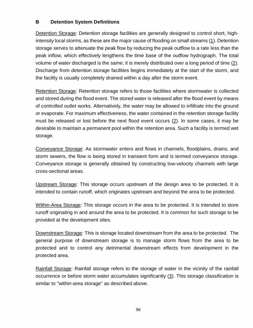
96
B Detention System Definitions
Detention Storage: Detention storage facilities are generally designed to control short, high-intensity local storms, as these are the major cause of flooding on small streams (1). Detention storage serves to attenuate the peak flow by reducing the peak outflow to a rate less than the peak inflow, which effectively lengthens the time base of the outflow hydrograph. The total volume of water discharged is the same; it is merely distributed over a long period of time (2). Discharge from detention storage facilities begins immediately at the start of the storm, and the facility is usually completely drained within a day after the storm event. Retention Storage: Retention storage refers to those facilities where stormwater is collected and stored during the flood event. The stored water is released after the flood event by means of controlled outlet works. Alternatively, the water may be allowed to infiltrate into the ground or evaporate. For maximum effectiveness, the water contained in the retention storage facility must be released or lost before the next flood event occurs (2). In some cases, it may be desirable to maintain a permanent pool within the retention area. Such a facility is termed wet storage. Conveyance Storage: As stormwater enters and flows in channels, floodplains, drains, and storm sewers, the flow is being stored in transient form and is termed conveyance storage. Conveyance storage is generally obtained by constructing low-velocity channels with large cross-sectional areas. Upstream Storage: This storage occurs upstream of the design area to be protected. It is intended to contain runoff, which originates upstream and beyond the area to be protected. Within-Area Storage: This storage occurs in the area to be protected. It is intended to store runoff originating in and around the area to be protected. It is common for such storage to be provided at the development sites. Downstream Storage: This is storage located downstream from the area to be protected. The general purpose of downstream storage is to manage storm flows from the area to be protected and to control any detrimental downstream effects from development in the protected area. Rainfall Storage: Rainfall storage refers to the storage of water in the vicinity of the rainfall occurrence or before storm water accumulates significantly (3). This storage classification is similar to "within-area storage" as described above.
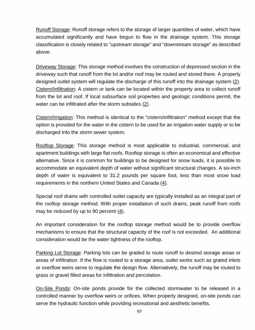
97
Runoff Storage: Runoff storage refers to the storage of larger quantities of water, which have accumulated significantly and have begun to flow in the drainage system. This storage classification is closely related to "upstream storage" and "downstream storage" as described above. Driveway Storage: This storage method involves the construction of depressed section in the driveway such that runoff from the lot and/or roof may be routed and stored there. A properly designed outlet system will regulate the discharge of this runoff into the drainage system (2). Cistern/Infiltration: A cistern or tank can be located within the property area to collect runoff from the lot and roof. If local subsurface soil properties and geologic conditions permit, the water can be infiltrated after the storm subsides (2). Cistern/Irrigation: This method is identical to the "cistern/infiltration" method except that the option is provided for the water in the cistern to be used for an irrigation water supply or to be discharged into the storm sewer system. Rooftop Storage: This storage method is most applicable to industrial, commercial, and apartment buildings with large flat roofs. Rooftop storage is often an economical and effective alternative. Since it is common for buildings to be designed for snow loads, it is possible to accommodate an equivalent depth of water without significant structural changes. A six-inch depth of water is equivalent to 31.2 pounds per square foot, less than most snow load requirements in the northern United States and Canada (4). Special roof drains with controlled outlet capacity are typically installed as an integral part of the rooftop storage method. With proper installation of such drains, peak runoff from roofs may be reduced by up to 90 percent (4). An important consideration for the rooftop storage method would be to provide overflow mechanisms to ensure that the structural capacity of the roof is not exceeded. An additional consideration would be the water tightness of the rooftop. Parking Lot Storage: Parking lots can be graded to route runoff to desired storage areas or areas of infiltration. If the flow is routed to a storage area, outlet works such as grated inlets or overflow weirs serve to regulate the design flow. Alternatively, the runoff may be routed to grass or gravel filled areas for infiltration and percolation. On-Site Ponds: On-site ponds provide for the collected stormwater to be released in a controlled manner by overflow weirs or orifices. When properly designed, on-site ponds can serve the hydraulic function while providing recreational and aesthetic benefits.
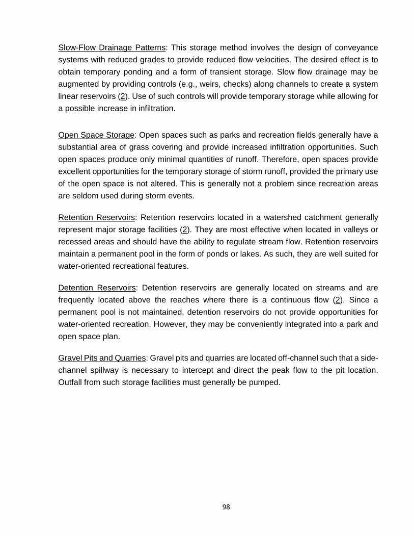
98
Slow-Flow Drainage Patterns: This storage method involves the design of conveyance systems with reduced grades to provide reduced flow velocities. The desired effect is to obtain temporary ponding and a form of transient storage. Slow flow drainage may be augmented by providing controls (e.g., weirs, checks) along channels to create a system linear reservoirs (2). Use of such controls will provide temporary storage while allowing for a possible increase in infiltration.
Open Space Storage: Open spaces such as parks and recreation fields generally have a substantial area of grass covering and provide increased infiltration opportunities. Such open spaces produce only minimal quantities of runoff. Therefore, open spaces provide excellent opportunities for the temporary storage of storm runoff, provided the primary use of the open space is not altered. This is generally not a problem since recreation areas are seldom used during storm events. Retention Reservoirs: Retention reservoirs located in a watershed catchment generally represent major storage facilities (2). They are most effective when located in valleys or recessed areas and should have the ability to regulate stream flow. Retention reservoirs maintain a permanent pool in the form of ponds or lakes. As such, they are well suited for water-oriented recreational features. Detention Reservoirs: Detention reservoirs are generally located on streams and are frequently located above the reaches where there is a continuous flow (2). Since a permanent pool is not maintained, detention reservoirs do not provide opportunities for water-oriented recreation. However, they may be conveniently integrated into a park and open space plan. Gravel Pits and Quarries: Gravel pits and quarries are located off-channel such that a side- channel spillway is necessary to intercept and direct the peak flow to the pit location. Outfall from such storage facilities must generally be pumped.
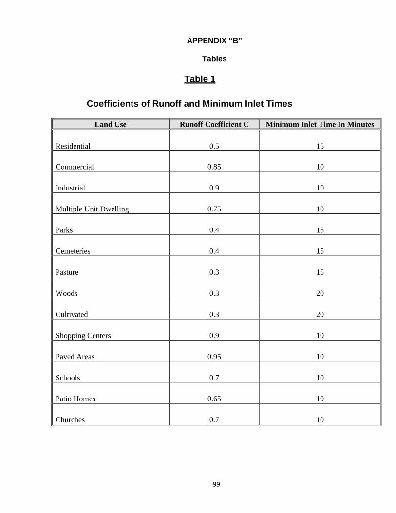
99
APPENDIX “B”
Tables
Table 1
Coefficients of Runoff and Minimum Inlet Times
Land Use Runoff Coefficient C Minimum Inlet Time In Minutes Residential
0.5
15
Commercial
0.85
10
Industrial
0.9
10
Multiple Unit Dwelling
0.75
10
Parks
0.4
15
Cemeteries
0.4
15
Pasture
0.3
15
Woods
0.3
20
Cultivated
0.3
20
Shopping Centers
0.9
10
Paved Areas
0.95
10
Schools
0.7
10
Patio Homes
0.65
10
Churches
0.7
10
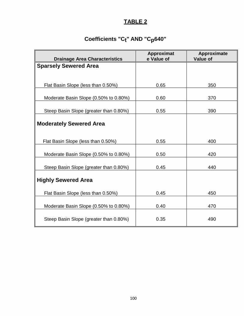
100
TABLE 2
Coefficients "Ct" AND "Cp640"
Drainage Area Characteristics
Approximate Value of
Approximate Value of
Sparsely Sewered Area
Flat Basin Slope (less than 0.50%)
0.65
350
Moderate Basin Slope (0.50% to 0.80%)
0.60
370
Steep Basin Slope (greater than 0.80%)
0.55
390 Moderately Sewered Area
Flat Basin Slope (less than 0.50%)
0.55
400
Moderate Basin Slope (0.50% to 0.80%)
0.50
420
Steep Basin Slope (greater than 0.80%)
0.45
440 Highly Sewered Area
Flat Basin Slope (less than 0.50%)
0.45
450
Moderate Basin Slope (0.50% to 0.80%)
0.40
470
Steep Basin Slope (greater than 0.80%)
0.35
490
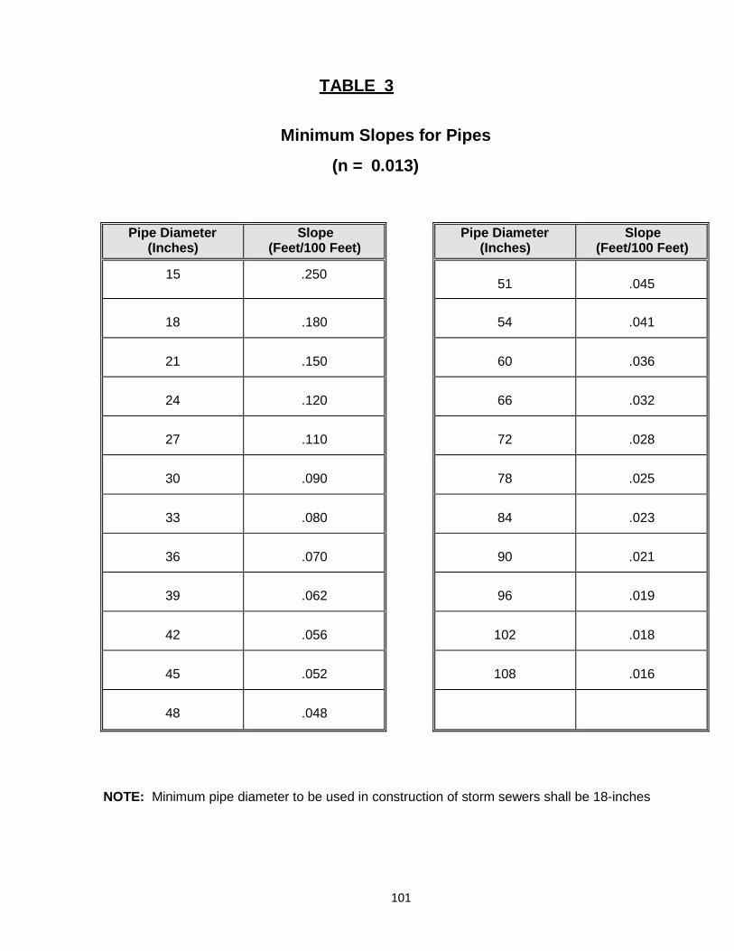
101
TABLE 3
Minimum Slopes for Pipes
(n = 0.013)
NOTE: Minimum pipe diameter to be used in construction of storm sewers shall be 18-inches
Pipe Diameter (Inches)
Slope (Feet/100 Feet)
15 .250
18
.180
21
.150
24
.120
27
.110
30
.090
33
.080
36
.070
39
.062
42
.056
45
.052
48
.048
Pipe Diameter (Inches)
Slope (Feet/100 Feet)
51
.045
54
.041
60
.036
66
.032
72
.028
78
.025
84
.023
90
.021
96
.019
102
.018
108
.016
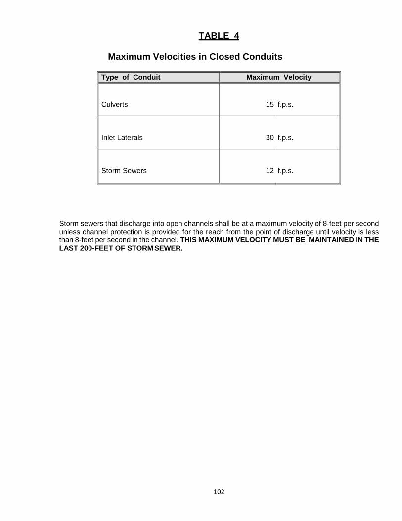
102
TABLE 4
Maximum Velocities in Closed Conduits Storm sewers that discharge into open channels shall be at a maximum velocity of 8-feet per second unless channel protection is provided for the reach from the point of discharge until velocity is less than 8-feet per second in the channel. THIS MAXIMUM VELOCITY MUST BE MAINTAINED IN THE LAST 200-FEET OF STORM SEWER.
Type of Conduit Maximum Velocity Culverts
15
f.p.s.
Inlet Laterals
30
f.p.s.
Storm Sewers
12
f.p.s.
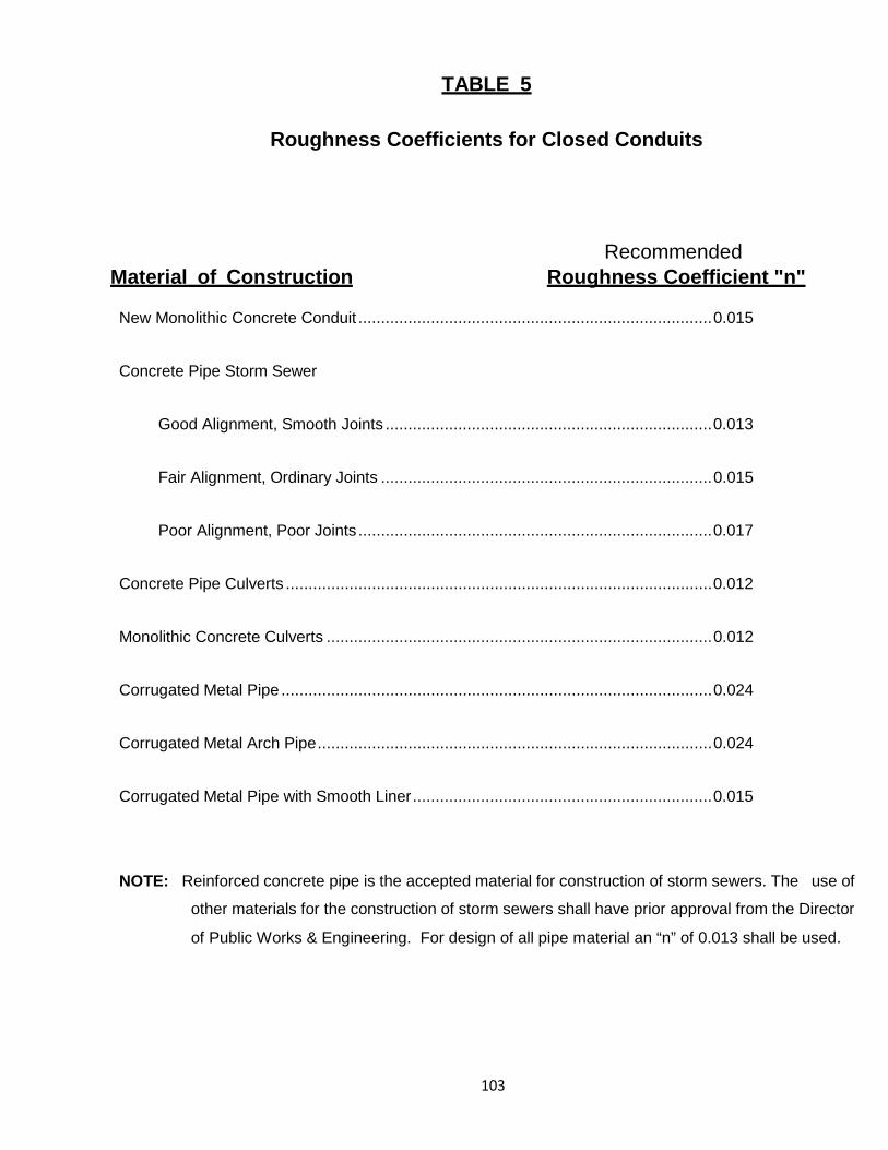
103
TABLE 5
Roughness Coefficients for Closed Conduits
Recommended Material of Construction Roughness Coefficient "n"
New Monolithic Concrete Conduit .............................................................................. 0.015
Concrete Pipe Storm Sewer
Good Alignment, Smooth Joints ........................................................................ 0.013
Fair Alignment, Ordinary Joints ......................................................................... 0.015
Poor Alignment, Poor Joints .............................................................................. 0.017
Concrete Pipe Culverts .............................................................................................. 0.012
Monolithic Concrete Culverts ..................................................................................... 0.012
Corrugated Metal Pipe ............................................................................................... 0.024
Corrugated Metal Arch Pipe ....................................................................................... 0.024
Corrugated Metal Pipe with Smooth Liner .................................................................. 0.015
NOTE: Reinforced concrete pipe is the accepted material for construction of storm sewers. The use of
other materials for the construction of storm sewers shall have prior approval from the Director
of Public Works & Engineering. For design of all pipe material an “n” of 0.013 shall be used.
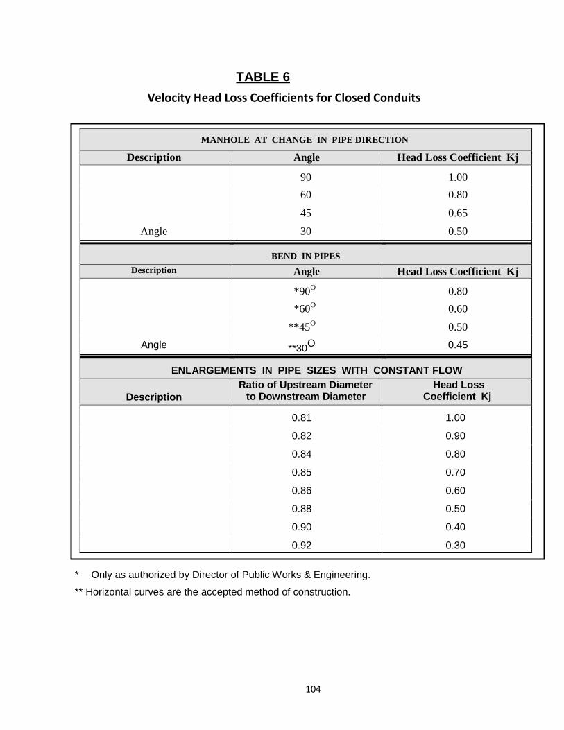
104
TABLE 6 Velocity Head Loss Coefficients for Closed Conduits
MANHOLE AT CHANGE IN PIPE DIRECTION
Description Angle Head Loss Coefficient Kj 90 1.00 60 0.80 45 0.65
Angle 30 0.50
BEND IN PIPES Description Angle Head Loss Coefficient Kj
*90O 0.80
*60O 0.60
**45O 0.50
Angle **30O 0.45
ENLARGEMENTS IN PIPE SIZES WITH CONSTANT FLOW
Description Ratio of Upstream Diameter
to Downstream Diameter Head Loss
Coefficient Kj 0.81 1.00
0.82 0.90
0.84 0.80
0.85 0.70
0.86 0.60
0.88 0.50
0.90 0.40
0.92 0.30 * Only as authorized by Director of Public Works & Engineering.
** Horizontal curves are the accepted method of construction.
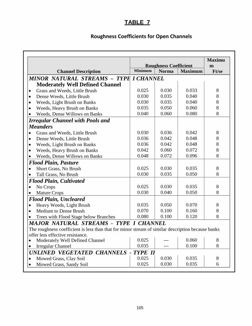
105
TABLE 7
Roughness Coefficients for Open Channels
Channel Description
Roughness Coefficient
Maximum
Minimum Norma
Maximum Ft/se MINOR NATURAL STREAMS – TYPE I CHANNEL
Moderately Well Defined Channel • Grass and Weeds, Little Brush 0.025 0.030 0.033 8 • Dense Weeds, Little Brush 0.030 0.035 0.040 8 • Weeds, Light Brush on Banks 0.030 0.035 0.040 8 • Weeds, Heavy Brush on Banks 0.035 0.050 0.060 8 • Weeds, Dense Willows on Banks 0.040 0.060 0.080 8 Irregular Channel with Pools and
Meanders • Grass and Weeds, Little Brush 0.030 0.036 0.042 8 • Dense Weeds, Little Brush 0.036 0.042 0.048 8 • Weeds, Light Brush on Banks 0.036 0.042 0.048 8 • Weeds, Heavy Brush on Banks 0.042 0.060 0.072 8 • Weeds, Dense Willows on Banks 0.048 0.072 0.096 8 Flood Plain, Pasture • Short Grass, No Brush 0.025 0.030 0.035 8 • Tall Grass, No Brush 0.030 0.035 0.050 8 Flood Plain, Cultivated • No Crops 0.025 0.030 0.035 8 • Mature Crops 0.030 0.040 0.050 8 Flood Plain, Uncleared • Heavy Weeds, Light Brush 0.035 0.050 0.070 8 • Medium to Dense Brush 0.070 0.100 0.160 8 • Trees with Flood Stage below Branches 0.080 0.100 0.120 8 MAJOR NATURAL STREAMS - TYPE I CHANNEL The roughness coefficient is less than that for minor stream of similar description because banks offer less effective resistance. • Moderately Well Defined Channel 0.025 --- 0.060 8 • Irregular Channel 0.035 --- 0.100 8 UNLINED VEGETATED CHANNELS - TYPE II
• Mowed Grass, Clay Soil 0.025 0.030 0.035 8 • Mowed Grass, Sandy Soil 0.025 0.030 0.035 6
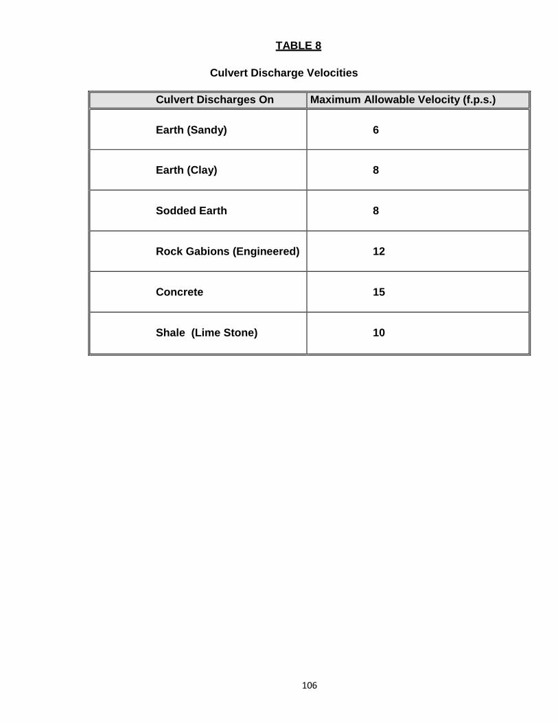
106
TABLE 8
Culvert Discharge Velocities
Culvert Discharges On Maximum Allowable Velocity (f.p.s.) Earth (Sandy)
6
Earth (Clay)
8
Sodded Earth
8
Rock Gabions (Engineered)
12
Concrete
15
Shale (Lime Stone)
10
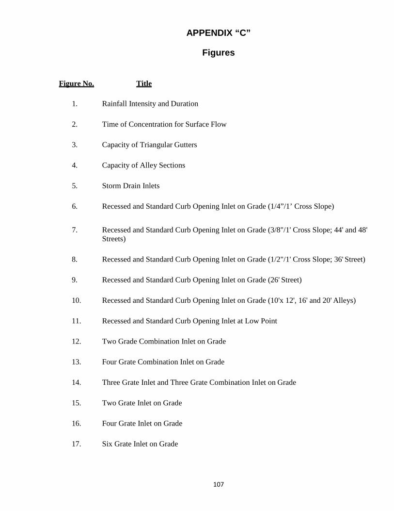
107
APPENDIX “C”
Figures
Figure No. Title
1. Rainfall Intensity and Duration
2. Time of Concentration for Surface Flow
3. Capacity of Triangular Gutters
4. Capacity of Alley Sections
5. Storm Drain Inlets
6. Recessed and Standard Curb Opening Inlet on Grade (1/4”/1’ Cross Slope)
7. Recessed and Standard Curb Opening Inlet on Grade (3/8"/1' Cross Slope; 44' and 48' Streets)
8. Recessed and Standard Curb Opening Inlet on Grade (1/2"/1' Cross Slope; 36' Street)
9. Recessed and Standard Curb Opening Inlet on Grade (26' Street)
10. Recessed and Standard Curb Opening Inlet on Grade (10'x 12', 16' and 20' Alleys)
11. Recessed and Standard Curb Opening Inlet at Low Point
12. Two Grade Combination Inlet on Grade
13. Four Grate Combination Inlet on Grade
14. Three Grate Inlet and Three Grate Combination Inlet on Grade
15. Two Grate Inlet on Grade
16. Four Grate Inlet on Grade
17. Six Grate Inlet on Grade
108
Figure No. Title
18. Combination Inlet at Low Point
19. Grate Inlet at Low Point
20. Drop Inlet at Low Point
21. Capacity of Circular Pipes Flowing Full
22. Open Channel Types
23. Headwater Depth for Box Culverts with Inlet Control
24. Headwater Depth for Concrete Pipe Culverts with Inlet Control
25. Head for Concrete Box Culverts Flowing Full
26. Head for Concrete Pipe Culverts Flowing Full
27. Critical Depth of Flow for Rectangular Conduits
28. Critical Depth of Flow for Circular Conduits
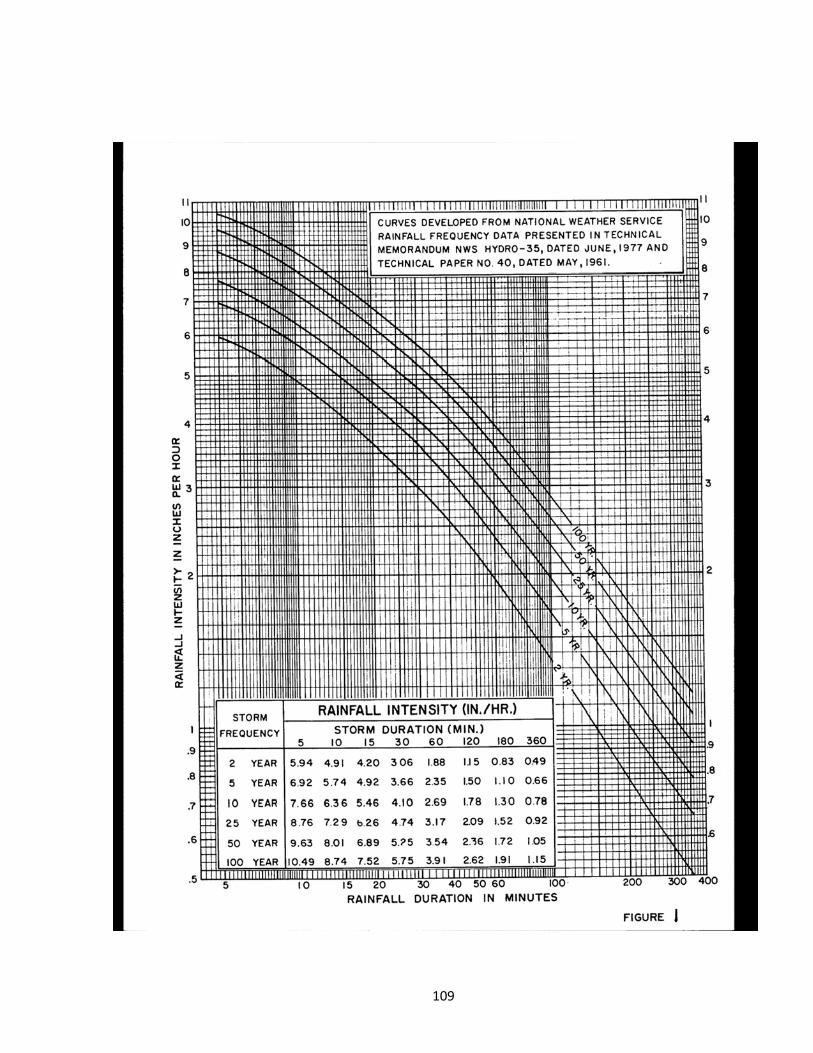
109
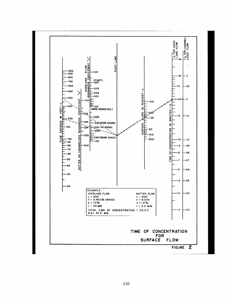
110
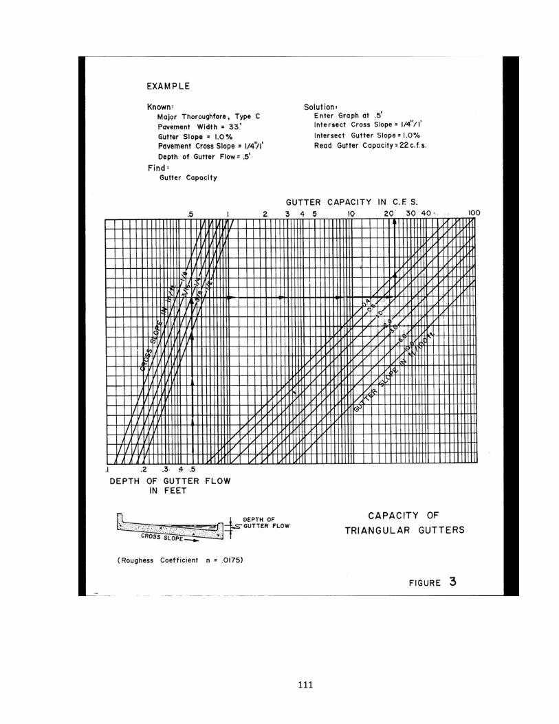
111