City of Phoenix Streetlighting Layout Guidelines of Phoenix Streetlighting Layout Guidelines Final...
47
City of Phoenix Streetlighting Layout Guidelines Final March 2013 These guidelines supersede all other guidelines. This document is in accordance with the City of Phoenix Streetlighting Policy originally adopted by city council July 1961 Amendment approved by City Council March 1967 Amendment approved by City Council September 1973 Amendment approved by City Council January 27, 1975 Amendment approved by City Council June 5, 1978 Amendment approved by City Council July 1, 1990 Amendment approved by City Council June 18, 1996 March 2013
Transcript of City of Phoenix Streetlighting Layout Guidelines of Phoenix Streetlighting Layout Guidelines Final...

City of Phoenix Streetlighting Layout Guidelines
Final
March 2013
These guidelines supersede all other guidelines.
This document is in accordance with the City of Phoenix Streetlighting Policy originally adopted by city council July 1961
Amendment approved by City Council March 1967 Amendment approved by City Council September 1973 Amendment approved by City Council January 27, 1975 Amendment approved by City Council June 5, 1978 Amendment approved by City Council July 1, 1990 Amendment approved by City Council June 18, 1996
March 2013

ii
Table of Contents
Table of Contents.................................................................................................. ii List of Figures...................................................................................................... iii List of Tables....................................................................................................... iv INTRODUCTION ................................................................................................... 5 1. RESIDENTIAL & COMMERCIAL DEVELOPMENT PROCESS .................... .6
1.1 RESIDENTIAL & COMMERCIAL STREETLIGHT HANDBOOK ............6 1.2 SUPPLEMENTAL DEVELOPMENT GUIDELINES .............................. .10 1.3 STREETLIGHT LAYOUT CHECKLIST................................................. .17 1.4 CONSTRUCTION PLAN SUBMITTALS ............................................... .21
2. CAPITAL IMPROVEMENT PROJECTS (CIP)............................................. 24 2.1 GENERAL REQUIREMENTS............................................................... 24 2.2 SALT RIVER PROJECT (SRP) NOTES ............................................... 25 2.3 ARIZONA PUBLIC SERVICE (APS) NOTES ....................................... 26
3. STREETLIGHT LOCATION LAYOUTS ....................................................... .30 4. MISCELLANEOUS...................................................................................... 42
4.1 DECORATIVE LIGHTING .................................................................... 42 4.2 BRIDGE SPECIFICATIONS .................................................................. 42 4.3 PAINT MAINTENANCE AGREEMENT ................................................. 42
iii
List of Figures
Figure 1: Streetlight Standard Sheet Format Sheet 1 ........................................ 12 Streetlight Standard Sheet Format Sheet 2 ........................................ 13 Streetlight Standard Sheet Format Sheet 3 ........................................ 14
Figure 2: Flowchart of DSD Process .................................................................. 23 Figure 3: Flowchart of CIP Process ................................................................... 29 Figure 4: Typical Residential Street Spacing ..................................................... 31 Figure 5: Arterial Street Staggered – No Median ............................................... 32 Figure 6: Arterial Intersection ............................................................................. 33 Figure 7: Typical Collector Street Spacing ......................................................... 34 Figure 8: Local/Local Roundabout ..................................................................... 35 Figure 9: Football Island .................................................................................... 36 Figure 10: Baseball Island ................................................................................. 37 Figure 11: Choker .............................................................................................. 38 Figure 12: Chicane............................................................................................. 39 Figure 13: Semi-Diverter .................................................................................... 40 Figure 14: Elbow (Dog-Leg) Intersections.......................................................... 41 Figure 15: CIP Bid Tabulation ............................................................................ 47

iv
List of Tables Table 1: Spacing and Mounting Height Criteria ................................................ 10 Table 2: DSD Process For Streetlighting Submittals ........................................ 22 Table 3: CIP Process For Streetlighting Submittals .......................................... 28

INTRODUCTION Residential & Commercial Development Projects
Developers of residential subdivisions, apartments, condominiums, commercial, industrial projects and all permitees are responsible for the design, materials, and installation costs of all streetlighting on public streets within and adjacent to their projects. The unique status of ‘shared ownership’ of the streetlight system requires a unique approach to streetlight design. The City of Phoenix owns the poles and fixtures and the utility companies own the electrical service. The streetlight Design Guidelines have been created to aid developers and their design professionals to create a layout that will meet City of Phoenix streetlight guidelines and provide the utility company a standard design format from which to start their streetlight electrical service design. The submittal process for streetlight layout review is explained step by step with a graphic representation to simplify this process. Computer Aided Drafting (CAD) details and notes are provided to ensure a consistent and up to date design. Specifications and an approved materials list will assist the contractor in constructing a system that meets City of Phoenix requirements. The intent of this manual is to help the developer understand City of Phoenix streetlight layout procedure and installation requirements allowing for a straightforward design and construction process.
Capital Improvement Projects
The City of Phoenix regularly constructs Capital Improvement Projects, including arterial street improvements and street modernization projects throughout the City and streetlighting is typically a part of those projects. The engineering consultant is responsible for the design of the project including the streetlight layout. The unique status of ‘shared ownership’ of the streetlight system requires a unique approach to streetlight design. The City of Phoenix owns the poles and fixtures and the utility companies own the electrical service. The Design Guidelines have been created to aid the consultant and his streetlight design professional to design a layout that will meet City of Phoenix streetlight requirements and provide the utility company a standard design format from which to start their streetlight electrical service design. CAD details and notes are provided to ensure consistent CIP design format. The submittal process is explained step by step and includes graphic representation to simplify this process. The intent of this manual is to help the Capital Improvement Project design consultant understand City of Phoenix streetlight layout procedure, allowing for a straightforward design process.

1. RESIDENTIAL & COMMERCIAL DEVELOPMENT PROCESS 1.1 RESIDENTIAL & COMMERCIAL STREETLIGHT HANDBOOK
This document is to be used only as a guide to assist developers and their consultant for streetlight design for new development or redevelopment in the City of Phoenix. This document is not a statement of policy, nor does it supersede the City Council Approved Streetlight Lighting Policy amended July 18, 1996.
1.1.1 ARTERIAL STREETS
1.1.1.1 Spacing will be approximately 200 to 250 feet using 130 Watt
9,900 lumen 4,000K CRI Light Emitting Diode lighting with 20 year life photo control. Arterial streets are to be illuminated according to the Spacing and Mounting Height Criteria, see Table 1. Ideal spacing is 200 to 250 feet along the same side of the street; 100 to 150 feet between opposite sides of the street. In an effort to achieve reasonable uniformity, deviations away from the point of radius are permitted up to 25 feet. Any further deviation must be approved by Street Transportation Department, Streetlight Section.
1.1.1.2 Once the right-of-way permit is issued, adherence to pole
locations is expected. Exceptions are hereby granted for shifts up to 5± feet parallel to the roadway with approval of Street Transportation Streetlight Inspector. Where underground obstructions are encountered, any shift in pole placement must not interfere with a driveway. Shifts perpendicular to the roadway from permit locations will not be allowed without permission of the Street Transportation Department, Streetlight Section.
1.1.1.3 All poles are to be located approximately 1-foot back of sidewalk
where the sidewalk abuts the curb. Where the sidewalk is detached to create a landscaped area, poles are to be located approximately 4-feet back of the curb The goal is to keep obstructions including streetlights out of the sidewalk. Deviations must be approved by Street Transportation Department, Streetlight Section. Contact the Street Transportation Department, Streetlight Section, for any developments in Downtown Phoenix. .

1.1.2 COLLECTOR STREETS
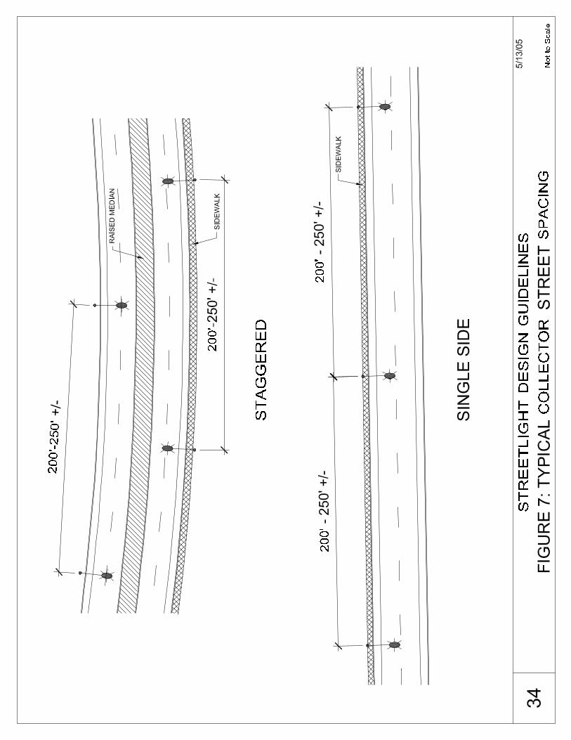
1.1.2.1 Spacing on collector streets will be approximately 200 feet and require one-sided lighting using 106 Watt 8,300 lumen 4,000K CRI Light Emitting Diode lighting with 20 year life photo control. Streetlight spacing should be according to the Spacing and Mounting Height Criteria, see Table 1. Collector streets are to be illuminated on both sides of the street when there are four (4) or more through lanes of traffic or when there is a raised, landscaped median. Streetlights are to be set back approximately 4-feet back of curb or approximately 1-foot back of sidewalk where the sidewalk abuts the curb.
1.1.3 LOCAL STREETS
1.1.3.1 Poles are to be placed at least 3-feet from back of curb to face
of pole. Where sidewalks abut the curb, the pole should be placed approximately 1-foot back of sidewalk.
1.1.3.2 Streetlight poles should be placed within approximately one-foot
laterally from the divisional property line. Streetlight spacing should be according to the Spacing and Mounting Criteria, see Table 1. Residential streetlight spacing should be approximately 200 - 250 feet using 67 Watt 5,300 lumen 4,000K CRI Light Emitting Diode lighting with 20 year life photo control, as per the City Council Approved Streetlighting Policy amended July 18, 1996.
1.1.4 LOW DENSITY RESIDENTIAL LIGHTING
1.1.4.1 Low Density Residential Lighting (residential areas of two or less
residences per acre) may qualify for a reduced level of lighting per City of Phoenix Policy adopted July 18, 1996. Requests must be submitted to the City of Phoenix Development Services Department, Team Leader.
1.1.5 DEVELOPER RESPONSIBILITY:
1.1.5.1 Developers of residential subdivisions, apartments,
condominiums, commercial, industrial projects, and all permitees are responsible for the design, materials, and installation costs of all streetlighting on public streets within and adjacent to their project.
1.1.5.2 Streetlighting plans expiration parallels Civil plans expiration and
requires re-submittal if Civil plans are updated.

1.1.5.3 Salt River Project (SRP) – Specific Requirements (Applicable{HYPERLINK "http://www.srpnet.com"}m)
1.1.5.3.1 All costs for streetlight installation including
construction and energization are to be addressed in
streetlight construction contract between developer and SRP.
1.1.5.4 Arizona Public Service (APS) – Specific Requirements
{HYPERLINK "http://www.aps.com"}m)
1.1.5.4.1 All costs for streetlight installation including construction and energization are to be addressed in streetlight construction contract between developer and APS.
1.1.6 DESIGN GUIDELINES
1.1.6.1 Streetlight layout and design shall include existing and known
future streetlight location information for all streets adjacent to and across from the proposed development.
1.1.6.2 Streetlights must be shown on all roadway right-of-way adjacent
to private developments. The developer shall pay all City inspection permit fees. Design conflicts shall be resolved by the developer to the satisfaction of the electrical utility company and City of Phoenix. It shall be the developer’s responsibility to coordinate conflict resolution with electric utility company facilities, including vertical clearances without compromise to the uniformity in the lighting design.
1.1.6.3 Future streetlight locations may be identified by researching
adjacent developments through the City’s KIVA System. Efforts shall be made during the design stage to assure that two (2) streetlights are located at each arterial street intersection and one streetlight at all other intersections. (When neighborhood traffic calming devices are installed additional lights may be required, see detailed drawings).
1.1.6.4 Label specific locations, sizes, and dimension from the center
line and/or monument line along with the following:
a. Existing and proposed underground utilities b. Existing and proposed overhead utilities c. Face of curb d. Width of sidewalk e. Width of any Public Utility Easement (PUE) f. Edge of right-of-way g. Edge of pavement
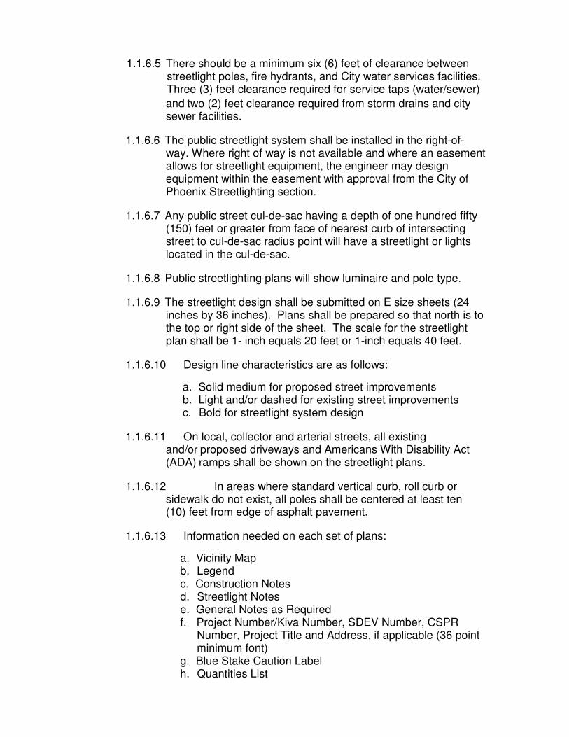
1.1.6.5 There should be a minimum six (6) feet of clearance between streetlight poles, fire hydrants, and City water services facilities. Three (3) feet clearance required for service taps (water/sewer)
and two (2) feet clearance required from storm drains and city sewer facilities.
1.1.6.6 The public streetlight system shall be installed in the right-of-
way. Where right of way is not available and where an easement allows for streetlight equipment, the engineer may design equipment within the easement with approval from the City of Phoenix Streetlighting section.
1.1.6.7 Any public street cul-de-sac having a depth of one hundred fifty
(150) feet or greater from face of nearest curb of intersecting street to cul-de-sac radius point will have a streetlight or lights located in the cul-de-sac.
1.1.6.8 Public streetlighting plans will show luminaire and pole type.
1.1.6.9 The streetlight design shall be submitted on E size sheets (24
inches by 36 inches). Plans shall be prepared so that north is to the top or right side of the sheet. The scale for the streetlight plan shall be 1- inch equals 20 feet or 1-inch equals 40 feet.
1.1.6.10 Design line characteristics are as follows:
a. Solid medium for proposed street improvements b. Light and/or dashed for existing street improvements c. Bold for streetlight system design
1.1.6.11 On local, collector and arterial streets, all existing
and/or proposed driveways and Americans With Disability Act (ADA) ramps shall be shown on the streetlight plans.
1.1.6.12 In areas where standard vertical curb, roll curb or
sidewalk do not exist, all poles shall be centered at least ten (10) feet from edge of asphalt pavement.
1.1.6.13 Information needed on each set of plans:
a. Vicinity Map b. Legend c. Construction Notes d. Streetlight Notes e. General Notes as Required f. Project Number/Kiva Number, SDEV Number, CSPR
Number, Project Title and Address, if applicable (36 point minimum font)
g. Blue Stake Caution Label h. Quantities List

i. City Project Number, if applicable j. Utility provider
1.2 SUPPLEMENTAL DEVELOPMENT GUIDELINES
1.2.1 SPACING SUMMARY
1.2.1.1 Streetlight spacing for new development should be in
accordance with Table 1 which summarizes City of Phoenix Streetlight Policy adopted by City of Phoenix City Council July 18, 1996.
Table 1: Spacing and Mounting Height Criteria
Classification
Utility Company
Watts
Lumens
Mounting Height
*Standard Spacing
*Spacing Type
Arterial (7lanes or more /
median island wider than 62’)
SRP
130W
9,900
35'
200-250’
Double-Sided
Staggered
Arterial (Narrower than 62’)
SRP
130W
9,900
35'
200-250’
Single Sided
Collector (Median island or wider than 62’)
SRP
106W
8,300
35'
200-250’
Double-Sided Staggered
Collector (Narrower than 62’)
SRP
106W
8,300
35'
200’
Single Sided
Local SRP 67W 5,300 26' 250’ Single Sided Arterial (7lanes or
more / median island wider than
62’)
APS
130W
9,900
34'-3”
200-250’
Double-Sided
Staggered
Arterial (Narrower than 62’)
APS
130W
9,900
34'-3"
200-250’
Single Sided
Collector (Median island or wider
than 62’)
APS
106W
8,300
32'-11”
200-250’
Double-Sided Staggered
Collector (Narrower than 62’)
APS
106W
8,300
32'-11”
200’
Single Sided
Local APS 67W 5,300 25'-11" 250’ Single Sided
* Existing power poles, safety considerations and traffic volumes may impact spacing and single/double sided streetlight installation requirements and will be determined by Street Transportation Department. Double sided spacing shown above is the distance between poles on the same side.

1.2.1.2 In order to achieve reasonable uniformity, deviations in this spacing may be permitted up to 25 feet. Any further deviation must be approved by Street Transportation Department, Streetlight Section
1.2.1.3 Private streetlights should be labeled as such. Streetlighting on
private streets is approved by Planning Department and Development Services Department per their requirements at review.
1.2.1.4 Streetlight poles should be set approximately 4 feet back of
curb. Where the sidewalk abuts the back of curb, poles should be located approximately 1 foot back of sidewalk. In cases where the streetlights facilities are in conflict with underground or overhead utilities streetlights may be set a minimum of two feet back of curb. However any setback deviation must be approved by Street transportation department, Streetlighting section.
1.2.1.5 Contact the Street Transportation Department, Streetlight
Section, for developments in Downtown Phoenix.
1.2.1.6 All streetlight poles and equipment should be shown with station and offset dimension.
1.2.1.7 Streetlight equipment shall conform to approved manufacturers
per current utility company standards.
1.2.1.8 When proposed streetlighting is in near vicinity of an airport runway, the developer shall provide all necessary pole height clearance calculations for review by COP Streetlighting.
1.2.1.9 Provide additional details of any items not covered by COP
standard details.
1.2.1.10 Streetlight general notes as provided by COP. See General notes.
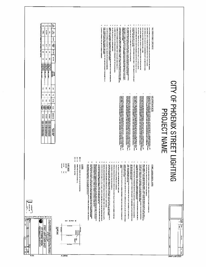
1.2.1.11 Construction plan sheet format to follow COP standards.
CAD details and standards will be provided by COP Streetlight Department. The standard sheet format is shown in Figure 1.
1.2.1.12 All items as described on streetlight design checklist.


1.2.2 GENERAL NOTES TO BE INCLUDED ON STREETLIGHT LAYOUT
COVER SHEET The following information is provided to emphasize critical work and is intended to supplement the specifications.
1. The contractor shall comply with State and City statutes and ordinances.
2. Prior to submittal, the streetlight designer shall examine all general
construction drawings and visit the construction site to become familiar with existing conditions under which they will operate and which will in any way affect the work under the contract.
3. The streetlight designer should verify dimensions at the site and
immediately report differences to the developer’s construction manager and not proceed with work until the construction manager renders a decision.
4. The electrical contractor shall comply with all licensing requirements set
forth by the state registrar of contractors office to perform work relating to streetlight installation in City of Phoenix right-of-way.
5. One dry utility permit for each City of Phoenix streetlight project, or phase if
a multi-phase project, shall be obtained by the contractor prior to construction.
6. Light poles shall be installed plumb, be adjusted to provide proper alignment
to the roadway being lighted and be properly grounded when the installation is completed.
7. Streetlights are inspected by the utility company and by City of Phoenix.
When accepted and energized, the utility company will install a streetlight number on each pole
8. Luminaires shall be installed level and include a lamp and photocell. The
luminaires shall be free of dust, dirt or anything that would impair the output of the light
9. Luminaires furnished with multi-tap ballasts shall be rewired or reconnected
to match the voltage supplied by the electric utility company. 10. Pole shall be set plumb in two directions, ninety (90) degrees apart.
11. Surplus excavation shall be disposed of by the contractor.
12. Wiring shall be installed per serving utility company standards. Conduit shall
be installed at the depth specified on their plans.

13. Conduit must be UL Rated and suitable for underground use per utility company requirement.
14. Connections shall be per serving utility company standards. Each pole shall
have a 8' x 5/8" copper clad ground rod driven beneath pull box. A #6 bare copper lead from the ground rod in pull box to landing lug in streetlight pole hand hole is required.
15. Excavation for pull boxes and material specifications shall be per utility
company requirement. 16. Trenches shall be installed per serving utility company standards. The use
of a common electric utility company trench is permitted. 17. It is the contractor's responsibility to contact the utility company for
coordination of the trenching and the installation of conduit. 18. It is the contractor's responsibility to restore all property, landscaping,
paving and driveways that are disturbed during streetlight construction to their original condition in conformance with MAG Specification section 107.9.
19. Prior to acceptance, the developer shall energize and operate the entire
roadway lighting system, from sunset to sunrise for two (2) consecutive days without interruption or failure. If a lamp or ballast should fail, it shall be immediately replaced. The developer shall be responsible for furnishing all personnel and equipment to successfully perform this test.
20. The contractor shall guarantee all work for a period of one year from the
date of final acceptance by the engineering manager, against imperfect workmanship, failure, malfunction of materials and/or equipment due to faulty or imperfect workmanship.
21. This guarantee is to be in writing to the City at the time of issuing final
acceptance. Materials and workmanship found to be defective within the warranty period shall be replaced without cost to the City.
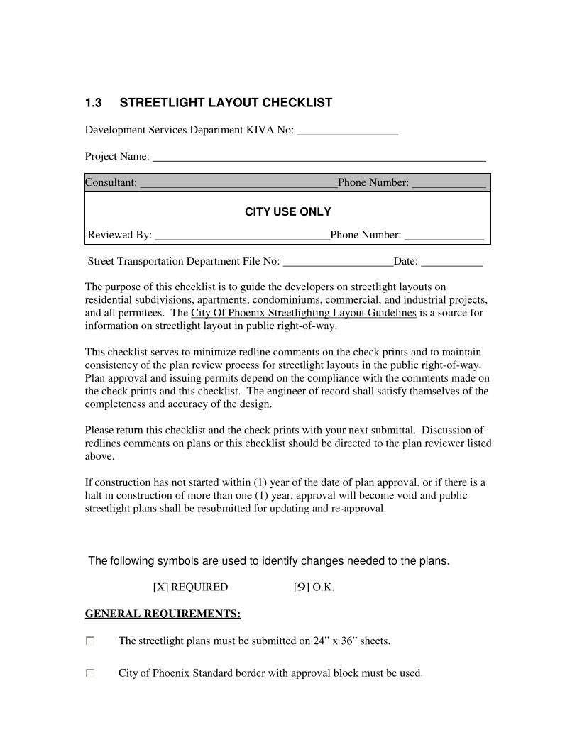
1.3 STREETLIGHT LAYOUT CHECKLIST
Development Services Department KIVA No:
Project Name:
Consultant: Phone Number:
CITY USE ONLY
Reviewed By: Phone Number:
Street Transportation Department File No: Date:
The purpose of this checklist is to guide the developers on streetlight layouts on
residential subdivisions, apartments, condominiums, commercial, and industrial projects,
and all permitees. The City Of Phoenix Streetlighting Layout Guidelines is a source for
information on streetlight layout in public right-of-way.
This checklist serves to minimize redline comments on the check prints and to maintain
consistency of the plan review process for streetlight layouts in the public right-of-way.
Plan approval and issuing permits depend on the compliance with the comments made on
the check prints and this checklist. The engineer of record shall satisfy themselves of the
completeness and accuracy of the design.
Please return this checklist and the check prints with your next submittal. Discussion of
redlines comments on plans or this checklist should be directed to the plan reviewer listed
above.
If construction has not started within (1) year of the date of plan approval, or if there is a
halt in construction of more than one (1) year, approval will become void and public
streetlight plans shall be resubmitted for updating and re-approval.
The following symbols are used to identify changes needed to the plans.
[X] REQUIRED [9] O.K.
GENERAL REQUIREMENTS:
The streetlight plans must be submitted on 24” x 36” sheets.
City of Phoenix Standard border with approval block must be used.

Copy of Preliminary Plat or Site Plan.
The scale must be shown on the plans 1” = 20’ or 1” = 40”
Graphic Scale
A north arrow is required on each sheet.
A vicinity or site location map is required on the cover sheet.
The developer’s name, address and phone number must be shown on the cover
sheet.
The Streetlight Design Professional name, address and phone number must be
shown on the cover sheet.
Project title block filled out with name and location of project.
Project Number/KIVA #/SDEV #, Project Title and Address, if applicable (36
font minimum font) must be shown on the cover sheet.
Blue Stake Caution Label must be shown on each plan sheet.
An index of sheets is required.
The minimum height of all text and symbols must be 0.1" (one-tenth of one inch).
Show and label all abutting streets.
Show landscape and abutting street(s).
Show setbacks and proposed landscape concept.
Show location of retentions basins and retaining walls.
Identify location – show site and adjacent parcels.
Show dimensions for FOC on all intersection street legs per the current City of
Phoenix standards.

Show existing and proposed driveway locations.
Label adjacent zoning and land use.
Show lot lines and dimensions.
The current COP General Notes must be shown on the cover or detail sheet.
All plan sheets shall display construction notes pertinent to each sheet.
Construction notes indicating all equipment to be installed, removed, or relocated.
The following information is required for each proposed and existing street within
and adjacent to the development:
a. Name b. Right-of-way width
c. Improved width of street, typically street centerline to back-of-curb
dimensions
d. Tract “ “ for private streets
All existing and proposed waterlines and fire hydrants shall be shown.
All existing and proposed overhead and underground utilities shall be shown
Locate proposed trees at least 20’ from a proposed streetlight pole location.
There should be a minimum six (6) feet of clearance between streetlight poles and
fire hydrants, City water facilities. Three (3) feet clearance required for service
taps (water/sewer) and two (2) feet clearance required from storm drains and city
sewer facilities. Provide dimensional ties to fire hydrants where potential
conflicts may occur (within 10’ of streetlight pole).
All proposed and existing streetlights within 300’ from the first proposed
streetlight should be shown with stationing and dimensional ties to the street
centerline.
Proposed streetlights in residential areas should be located within 5’ of property
lines. Lights located in residential areas but not adjacent to homes may be shown
by station and offset only.
Show all project phasing on the plans.
Provide a quantity tabulation of the number of streetlight poles on the cover sheet.

Quantities must be tabulated separately by phase. Private streetlights must be
tabulated separately from public streetlights.
Identify utility provider on the plan set.
Provide a legend on the plans identifying the following items:
a. Luminaire description
1. Local street – 67 watt, 5,300 lumen, 4000K CRI Light Emitting Diode
2. Collector street – 106 watt, 8,300 lumen, 4000K CRI Light Emitting
Diode
3. Arterial street – 130 watt, 9,900 lumen, 4000K CRI Light
Emitting Diode
b. 20 year Photo Life Control
c. Luminaire mounting height
d. Pull Box size and type
e. Existing luminaire type, pole, and wattage
f. Traffic Signal Mounted Luminaire type, pole, and wattage
Coordinate streetlight plan with the engineer preparing other offsite improvement
plans.
Provide stationing on all plans.
Utility provider must be shown with all applicable utility notes.
Label specific locations, sizes, and dimension from center line and/or monument
line along with the following:
a. Existing and proposed underground utilities b. Existing and proposed overhead utilities
c. Face of curb
d. Width of sidewalk
e. Width on any PUE
f. Edge of right-of-way
g. Edge of pavement
On residential, collector and arterial streets, all existing and/or proposed
driveways and American Disability Act (ADA) ramps shall be shown on the
streetlight plans.

1.4 CONSTRUCTION PLAN SUBMITTALS Streetlight plans shall be submitted to Central Login at the Development Services Department. The steps in the approval process of streetlight construction drawings for Residential and Commercial development is described in Table 2 with a flowchart shown in Figure 2.
For questions regarding streetlight design, please contact (602) 262-7223 or go to the following websites:
Street Transportation Department website:
{ HYPERLINK "http://phoenix.gov/streets/reference/STREETLIGHTDEV" }
Planning and Development Department website: http://phoenix.gov/pdd/topics/index.html
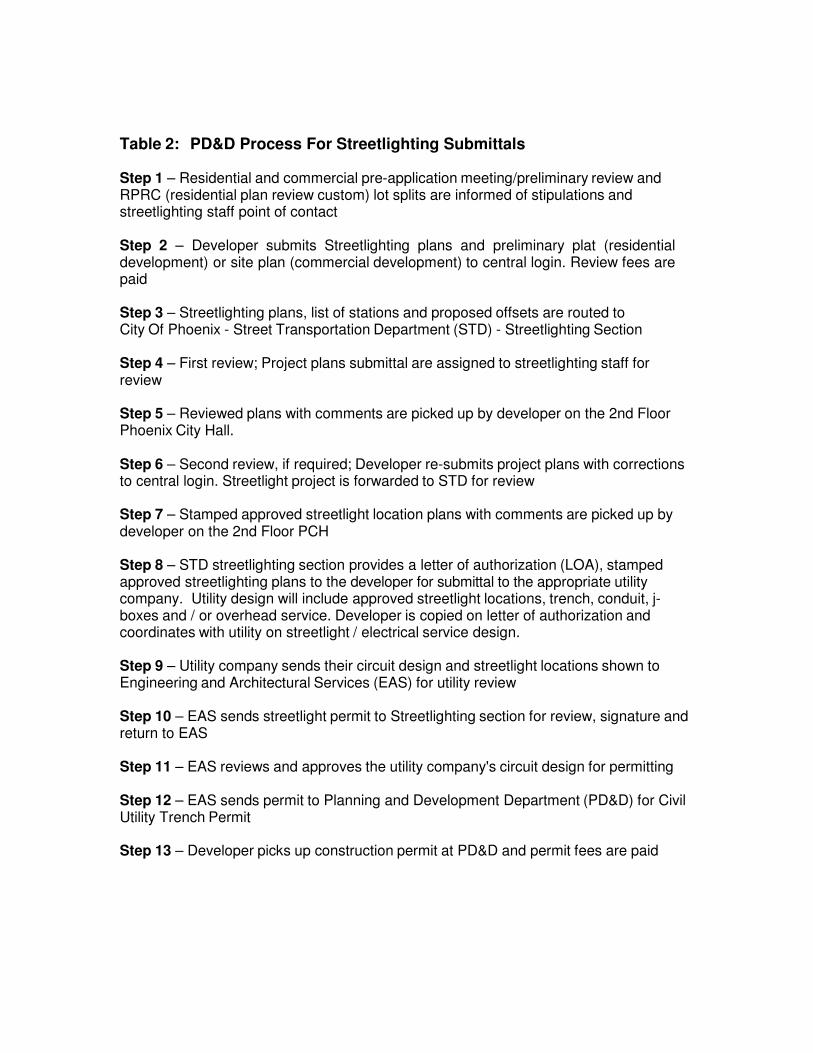
Table 2: PD&D Process For Streetlighting Submittals Step 1 – Residential and commercial pre-application meeting/preliminary review and RPRC (residential plan review custom) lot splits are informed of stipulations and streetlighting staff point of contact
Step 2 – Developer submits Streetlighting plans and preliminary plat (residential development) or site plan (commercial development) to central login. Review fees are paid
Step 3 – Streetlighting plans, list of stations and proposed offsets are routed to City Of Phoenix - Street Transportation Department (STD) - Streetlighting Section
Step 4 – First review; Project plans submittal are assigned to streetlighting staff for review
Step 5 – Reviewed plans with comments are picked up by developer on the 2nd Floor Phoenix City Hall.
Step 6 – Second review, if required; Developer re-submits project plans with corrections to central login. Streetlight project is forwarded to STD for review
Step 7 – Stamped approved streetlight location plans with comments are picked up by developer on the 2nd Floor PCH
Step 8 – STD streetlighting section provides a letter of authorization (LOA), stamped approved streetlighting plans to the developer for submittal to the appropriate utility company. Utility design will include approved streetlight locations, trench, conduit, j-boxes and / or overhead service. Developer is copied on letter of authorization and coordinates with utility on streetlight / electrical service design.
Step 9 – Utility company sends their circuit design and streetlight locations shown to Engineering and Architectural Services (EAS) for utility review
Step 10 – EAS sends streetlight permit to Streetlighting section for review, signature and return to EAS
Step 11 – EAS reviews and approves the utility company's circuit design for permitting
Step 12 – EAS sends permit to Planning and Development Department (PD&D) for Civil Utility Trench Permit
Step 13 – Developer picks up construction permit at PD&D and permit fees are paid
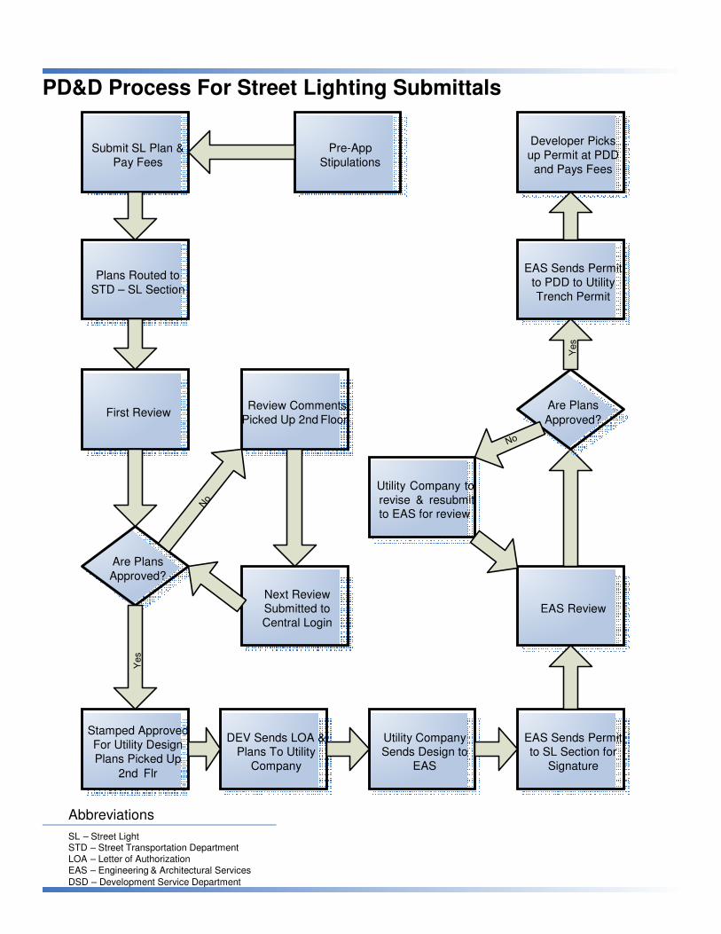
Yes
Yes
PD&D Process For Street Lighting Submittals
Submit SL Plan & Pay Fees
Pre-App Stipulations
Developer Picks up Permit at PDD and Pays Fees
Plans Routed to STD – SL Section
EAS Sends Permit to PDD to Utility Trench Permit
First Review Review Comments
Picked Up 2nd Floor
Are Plans
Approved?
Utility Company to revise & resubmit to EAS for review
Are Plans Approved?
Next Review Submitted to Central Login
EAS Review
Stamped Approved For Utility Design Plans Picked Up
2nd Flr
DEV Sends LOA & Plans To Utility
Company
Utility Company Sends Design to
EAS
EAS Sends Permit to SL Section for
Signature
Abbreviations
SL – Street Light STD – Street Transportation Department LOA – Letter of Authorization EAS – Engineering & Architectural Services
DSD – Development Service Department

2. CAPITAL IMPROVEMENT PROJECTS (CIP)
2.1 GENERAL REQUIREMENTS 2.1.1 The Contractor shall furnish and install all equipment and material as
specified in the bid documents and in compliance with all of the applicable details, specifications, rules and regulations of the Agencies involved. In the case of any conflicting requirements the most stringent requirement shall prevail.
2.1.2 The Design submittal package shall consist of three (3) copies of all
Equipment/Material to be installed and shall be submitted to City of Phoenix Streetlighting section with the paving plans, at 30% completion.
2.1.3 Prior to submitting a streetlight layout, the streetlight design consultant
shall examine all general construction drawings and visit the construction site to become familiar with existing conditions under which he will operate and which will in any way affect the work under the contract. The consultant shall also be aware of any additional requirements normally imposed by affected Utility Company and/or other regulatory agencies in constructing like work. No subsequent allowance will be make in this connection in the behalf of the Contractor for any error or negligence on his part.
2.1.4 Prior to ordering any materials or doing any work, the Contractor
should verify dimensions at the site. Immediately report differences to the COP Project Manager and do not proceed with work until the a decision is rendered. No extra charges or compensation will be allowed for differences in actual dimensions and dimensions indicated on the drawings
2.1.5 The Contractor shall comply with all licensing requirements set forth by
the State Register of Contractors office to perform work relating to streetlight installation in the right-of-way.
2.1.6 A project(s) underground utilities (Right-of-Way) permit(s) shall be
obtained by the Contractor prior to starting construction. The permit will be issued by the City of Phoenix to the Contractor after the award of the Contract.
2.1.7 For all new installations an authorization letter by City of Phoenix
streetlighting section shall be sent to the Utility authorizing the design and installation of facilities.
2.1.8 Cost for streetlight design shall be included in project scope.

2.1.9 Plans will show streetlight location, distance between streetlights, luminaire information, mounting heights & pole type.
2.1.9.1 Bid item format is included and should be used as a guideline for bid
item descriptions. See Figure 15. 2.1.9.2 Contractor is responsible for obtaining required variances prior to
submitting CIP drawings to the utilities. 2.1.9.3 Contractor is responsible for verifying vertical and horizontal
clearances to existing overhead lines and poles when placing new streetlights.
2.2 SALT RIVER PROJECT (SRP) NOTES The following SRP plan notes are to be part of the notes listed on the plan for CIP projects in SRP service area:
2.2.1 Contractor shall call SRP for a pre-construction meeting prior to any
excavation at (602) 236-6300. 2.2.2 Contractor will supply all trenching and conduit if requested by COP
Project Manager. 2.2.3 Contractor will stake streetlights per City of Phoenix approved
streetlighting construction drawings. 2.2.4 Grade stake will be set within two (2) feet of J-box location.
2.2.5 Contractor will coordinate with SRP and City of Phoenix for de-
energizing of streetlight conductor. 2.2.6 Ground rod will be provided and installed by Contractor in SRP J-box
at each streetlight location. 2.2.7 #6 bare copper ground wire to be attached from grounding lug on
streetlight pole to ground rod in J-box. 2.2.8 If the Contractor installs the pole, the bare #6 copper ground wire shall
be connected from the ground rod in the SRP J-box to the ground connection in the pole hand-hole.
2.2.9 All trenching and conduit to be inspected by SRP. Do not backfill until
inspected. 2.2.10 SRP construction print must be used as a trenching reference.
Trenching variations must have written SRP designer approval. Follow

details for construction. Variations in trench route may result in a redesign fee payable by contractor.
2.2.11 Trenches should be straight, level and free of debris. All trench depths
measured from final grade to top of conduit (per SRP design) within all easements and right of way. Maintain minimum 6” clearance from water lines, 18” from all gas lines and 12” clearance from other utilities.
2.2.12 Use DB120 PVC for all straight conduit, 36”radius schedule 40 PVC
sweeps for all elbows. No reducers are allowed in conduit system, no couplings or bell ends are allowed at equipment locations. All conduits within road Right of Way or PUE must be red.
2.2.13 Retaining walls are required adjacent to equipment where the grade
slope is greater than 30” in 12’. 2.2.14 All conduit stub outs are to be capped and marked with electronic
marker and 7” red flag marking ribbon. 2.2.15 Hard caps are to be used for all stub outs below grade.
2.2.16 A mandrel inspection is required with SRP Inspector within 3 days of
final inspection. Contractor must provide 2 representatives, minimum 125-CFM trailer mounted compressor and all necessary attachments.
2.2.17 The Contractor is responsible for the integrity of all conduits until SRP
has installed conductors. 2.2.18 Backfill requirements for a trench in or under future pavement to be 1
part slurry mix in road right of way and in dirt to be ½ slurry mix and ½ slurry mix maximum under all SRP equipment.
2.2.19 See duct bank specifications for all duct bank encasement
requirements.
2.3 ARIZONA PUBLIC SERVICE (APS) NOTES The following APS plan notes are to be part of the notes listed on plans for CIP projects in APS service area:
2.3.1 Contractor shall contact APS inspector identified on the APS
construction drawing for pre-construction meeting prior to any excavation.
2.3.2 Contractor to supply all trench and conduit, per APS requirements,
unless otherwise noted.

2.3.3 Grade stake to be set within 2’ of J-Box location. 2.3.4 Contractor will coordinate with APS and City of Phoenix for de-
energizing of streetlight conductor. 2.3.5 Ground rod to be provided and installed by contractor in APS J-Box at
each streetlight location. 2.3.6 If the contractor installs the pole, a bare #6 copper ground wire shall be
connected from the ground rod in the APS J-Box to the ground connection in the hand hole.
2.3.7 All trench and conduit to be inspected by APS. Do note backfill until
inspected. 2.3.8 APS construction print must be used as a trenching reference.
Trenching variations must have written APS CSR approval. Follow details for construction. Variations in trench route may result in a redesign fee.
2.3.9 Contact APS for all trench and conduit specifications and
requirements. 2.3.10 Contractor is responsible for integrity of all conduits until APS has
installed conductors. 2.3.11 Contractor is responsible for obtaining required variances prior to
submitting CIP drawings to the utilities. 2.3.12 Contractor is responsible for verifying vertical and horizontal
clearances to existing overhead lines and poles when placing new streetlights.

Table 3: CIP Process For Streetlighting Submittals Includes Major Streets, Street Modernization, Sidewalk, Local Drainage and Special Projects
Step 1 – Streetlighting consultant prepares streetlight location plans, list of stations with proposed offsets and photometric analysis if requested, to be included with 70% design plans
Step 2 – Streetlight location plans and list of stations and proposed offsets are submitted (hard copy and electronically) to DCM Project Manager
Step 3 – DCM project manager places the electronic files for 70% design plans with streetlight locations and list of stations and proposed offsets, on the U: Drive with proper nomenclature and notifies streetlight section.
Step 4 – First review (10 days); Streetlight location plans and list of stations and proposed offsets are reviewed by streetlight section. Plans and comments are returned to DCM- project manager to be forwarded to streetlight consultant
Step 5 – Second Review (7 days), if necessary; Plans, stations and proposed offsets and comments are reviewed and returned to DCM-project manager and from PM to consultant
Step 6 – STD streetlight section sends letter of authorization (LOA), stamped approved streetlight location plans and stamped approved list of stations and proposed offsets to the appropriate utility company for streetlight design. Utility design will include approved streetlight locations, trench, conduit; j-boxes and /or overhead service. Consultant is copied on letter of authorization and coordinates with utility on streetlight / electrical service design
Step 7 – Utility company sends the circuit design and streetlight location plans to Engineering and Architectural Services (EAS) for utility review
Step 8 – EAS sends streetlight permit(s) showing the streetlight locations, to streetlight section for review, signature and return to EAS
Step 9 – EAS reviews and approves the utility company's circuit design for permitting
Step 10 – EAS sends streetlight permit to utility company construction department
Step 11 – Utility company or their contractor completes work
Step 12 – DCM – Project Manager informs streetlight section when streetlight work is completed

Yes
Yes
CIP Process For Street Lighting Submittals Includes Major Streets, Street Modernization, Sidewalk, Local Drainage and Special Projects
Submit SL Plan e-files and Hard Copy to DCM
Project Manager
Consultant
Prepares Street Light Plan
Utility Company or
their Contractor completes Work
DCM Project Manager places e-
files on U: Drive
EAS Sends Permit to Utility Company
First Review
Review Comments
Picked Up 5th
Floor
Are Plans Approved
Utility Company to revise & resubmit to EAS for review
Are Plans Approved
Next Review
Submit to DCM Project Manager
EAS Review
STD Sends LOA & Plans To Utility
Company
Utility Company Sends Design to
EAS
EAS Sends Permit to SL Section for
Signature
Abbreviations
SL – Street Light EAS – Engineering & Architectural Services STD – Street Transportation Department DCM – Design Construction Management LOA – Letter of Authorization

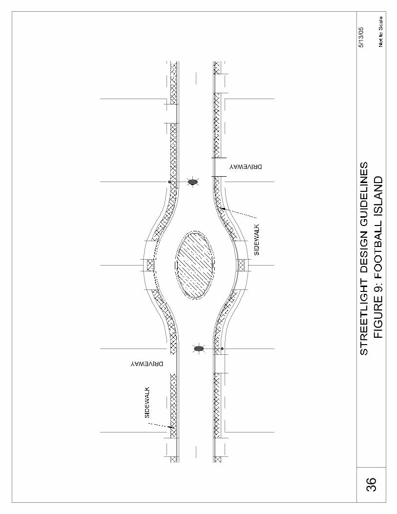
3. STREETLIGHT LOCATION LAYOUTS In order to provide the designer with guidelines for various roadway scenarios, typical roadway configurations with corresponding spacing recommendations are shown in Figures 4 through 14. These layouts are shown as examples only. The design engineer should use their professional judgment when designing all type of scenarios.


4. MISCELLANEOUS 4.1 DECORATIVE LIGHTING
Special consideration must first be made by the City of Phoenix staff before any approval is given for the design and installation of decorative streetlighting. Decorative streetlighting shall be limited to pre-approved types and styles and installed only on special projects identified by Street Transportation Department.
4.2 BRIDGE SPECIFICATIONS
4.2.1 This section applies to poles and luminaires installed on all bridge
decks regardless of utility service area. Bridge mounted pole details and specifications are provided by Arizona Public Service.
4.2.2 Consulting Engineer shall coordinate with bridge structural engineer to
design foundations for pole into bridge wall. See pole specifications for design criteria.
4.2.3 Cast in place junction box is required within 3’ of each pole mounted
on a bridge. 4.2.4 Conduit between junction boxes on a bridge shall be a minimum of 2.5”
in diameter. 4.2.5 Pole spacing will be in accordance with typical spacing criteria
corresponding to roadway designation as described in the design guidelines section.
4.2.6 Consulting Engineer shall provide detail showing the installation of
expansion couplings in bridge abutments.
4.3 PAINT MAINTENANCE AGREEMENT 4.3.1 The Association (Home Owner Association/Community/Neighborhood
Groups) shall paint the streetlights at the locations specified in Exhibit “A” and in accordance with the plans and specifications for City of Phoenix streetlights. The City agrees that it will allow the to utilize those portions of dedicated street rights- of-way indicated in Exhibit “A” for the purpose of painting the streetlights. The City further agrees that it will allow the to paint the streetlights with the color , or an appropriately similar color if said appropriately similar color is more

reasonably available than , as long as the appropriately similar color is approved by the City and used uniformly on all painted streetlight poles (i.e., no mixing of colors).
4.3.2 The Association shall be responsible for the painting and maintenance
of the paint of the streetlights in accordance with standards approved by the City. The Association shall thereafter maintain the paint finish on the streetlights in compliance with all City ordinances, including periodic retouching of the paint and repainting. The Association agrees that in the event it fails to properly maintain the paint of the streetlights, the City may, at its option, after written notice to the Association, provide the maintenance for the paint of the streetlights, the Association agrees to reimburse the City for its cost in maintenance for the painting of the streetlights only if the City uses the color , or the appropriately similar color described in paragraph 1 of this Agreement.
4.3.3 The Association agrees to indemnify and hold the City harmless from
any and all liability, including attorneys’ fees, costs of litigation, actions, loss, damage, injury, or claims of any character or nature arising directly or indirectly out of the initial painting or subsequent maintenance of the paint of the streetlights by the Association.
4.3.4 This Agreement shall be binding upon and shall inure to the benefit of
the successors and assigns of the parties. 4.3.5 This Agreement constitutes the entire understanding between the
parties relative to the matters addressed herein. This Agreement may be amended only by a written agreement fully executed by the parties.
4.3.6 This Agreement shall be governed by and construed in accordance
with the laws of the State of Arizona. In the event that litigation is necessary to enforce or interpret this Agreement, the parties consent to the jurisdiction and venue of the Maricopa County Superior Court.
4.3.7 In the event that any provision herein is determined to be legally
unenforceable, the remaining provisions shall nevertheless be carried into effect.
4.3.8 In the event of any litigation between or among the parties arising out
of the terms, conditions and obligations set forth in this Agreement, the prevailing party in such litigation shall be entitled to recover reasonable attorneys’ fees incurred in connection with such litigation.

4.3.9 Nothing contained in this Agreement shall be construed to create a
partnership, joint venture, agency or employer/employee relationship between the parties.
4.3.10 All statements and notices required or permitted to be given under this
Agreement shall be in writing, and shall be delivered either by personal service or forwarded by certified mail to the addresses shown below.
City: City of Phoenix
200 West Washington Street, 5th Floor Phoenix, Arizona 85003 Attention: Street Transportation Department
Association:
4.3.11 The Association shall procure and maintain for the duration of this
Agreement insurance against claims for injuries to persons or damages to property that may arise from or in connection with this Agreement by the Association, its agents, representatives, employees or contractors. The insurance requirements herein are minimum requirements for this agreement and in no way limit the indemnity covenants contained in this Agreement. The City in no way warrants that the minimum limits contained herein are sufficient to protect the Association from liabilities that might arise out of this Agreement for the Association, its agents, representatives, employees or contractors, and the Association is free to purchase such additional insurance as may be determined necessary.
(A) Minimum Coverage Requirements. The Association shall provide coverage at least as broad and within limits of liability not less than those stated below:
(I) Commercial general liability - occurrence form $2,000,000
(Form cg001, ed. 10/93 or any replacements thereof) (ii) General aggregate/for this agreement $1,000,000 (iii) Products-completed operations aggregate $1,000,000 (iv) Personal and advertising injury $1,000,000 (v) Each occurrence $1,000,000 (vi) Fire damage (any one fire) $50,000
(B) Policy provisions. The insurance policies furnished by Association are to contain, or be endorsed to contain, the following provisions: (I) the City, its officers, officials, agents, employees and volunteers are to

be named as additional insured with respect to liability arising out of the use and activities performed by or on behalf of the association, products, and completed operations of the association; (ii) commercial general liability insurance shall include broad form contractual liability coverage; (iii) the association’s insurance coverage shall be primary insurance with respect to the city, its officers, officials, agents, employees and volunteers; (iv) the association’s insurance shall apply separately to each insured against whom claim is made or suit is brought, except with respect to the limits of the insurers liability; (v) coverage provided by the association shall not be limited to the liability assumed under the indemnification provisions of this agreement; (vi) the policy shall contain a waiver against subrogation against the city, its officers, officials, agents, employees, and volunteers for losses arising from association’s operations, occupancy and use of the public right-of-way and/or other actions covered by association’s insurance.
(C) Prior Notice and Certificate of Insurance Required. Each insurance policy required by the insurance provisions of this Agreement shall not be suspended, voided, canceled by either party, reduced in coverage or in limits except after thirty (30) days prior written notice has been sent to the City, Street Transportation Department as set forth herein. Such notice shall be sent by certified mail, return receipt requested. Insurance is to be placed with insurers duly licensed or approved unlicensed companies in the state of Arizona and with a “best’s” rating of not less than a-:vii. The City in no way warrants that the above required minimum insurer rating is sufficient to protect the association from potential insurer insolvency. Association shall furnish the city with certificates of insurance (accord form or equivalent approved by the City) and with original endorsements affecting coverage as required by this Agreement. The certificates and endorsements for each insurance policy are to be signed by a person authorized by the insurer to bind coverage on its behalf. Any policy endorsements that restrict or limit coverage shall be clearly noted on the certificate of insurance. All certificates and endorsements shall be received and approved by the City prior to execution of this Agreement. Each insurance policy required by this Agreement must be in effect at or prior to execution of this Agreement and remain in effect for the duration of the Agreement. Failure to maintain the insurance policies required by this Agreement or to provide evidence of renewal shall be grounds for immediate termination of this Agreement. All certificates of insurance required by this Agreement shall be sent directly to the City at the address set forth herein. The City agreement number and description number shall be provided on the certificate of insurance. The City reserves the right to require complete certified copies of valid insurance policies required by this Agreement at any time.

(D)Any modification or variation from the insurance requirements in this Agreement shall be approved by the Street Transportation Department and Risk Management Department of the City, whose decision shall be final.
4.3.12. This Agreement may be cancelled pursuant to the provisions of
A.R.S.§ 38-511.

FIGURE 15: CIP BID TABULATION
Engineer's Estimate of Probable Cost
City of Phoenix Capital Improvement Project
Street Lighting
Item No. Description Unit Quantity Unit Price Amount
APS 8040 67W LED LUMINAIRE ON A 30'-6" POLE WITH A 6'x20" MAST ARM WITH ALL WIRING EA - $ - $0.00 APS 8040 106W LED LUMINAIRE ON A 38'-6" POLE WITH A 6'x20" MAST ARM WITH ALL WIRING EA - $ - $0.00 APS 8040 130W LED LUMINAIRE ON A 38'-6" POLE WITH A 8'x36" MAST ARM WITH ALL WIRING EA - $ - $0.00 SRP 67W LED LUMINAIRE ON A 24''-0" POLE WITH A 3' RADIUS MAST ARM WITH ALL WIRING EA - $ - $0.00 SRP 106W LED LUMINAIRE ON A 31''-6" POLE WITH A 6' RADIUS MAST ARM WITH ALL WIRING EA - $ - $0.00 SRP 130W LED LUMINAIRE ON A 31''-6" POLE WITH A 6' RADIUS MAST ARM WITH ALL WIRING EA - $ - $0.00 CUSTOM STREET LIGHT WITH MAST ARM AND LUMINAIRE WITH ALL WIRING EA - $ - $0.00 PULL BOX WITH ALL FUSING, GROUNDING, WIRING AND FLEX CONDUIT TO POLE EA - $ - $0.00 RELOCATE EXISTING STREET LIGHT POLE EA - $ - $0.00 REMOVE EXISTING STREET LIGHT POLE & PULL BOX - RETURN TO POWER COMPANY EA - $ - $0.00 REMOVE STREET LIGHT AND MAST ARM FROM POWER POLE EA - $ - $0.00 TRENCH AND CONDUIT PER UTILITY SPECIFICATIONS LF - $ - $0.00 - $ - $0.00
Subtotal Construction Costs $0.00 Contingency 5% - Total Estimated Cost -