CITY OF CALABASAS of Calabasas Geotechnical Guidelines March 2010 Page: i Table of Contents 1.0....
58
CITY OF CALABASAS DEPARTMENT OF PUBLIC WORKS MANUAL FOR THE PREPARATION OF GEOLOGIC AND GEOTECHNICAL REPORTS MARCH 2010
-
Upload
truongtuyen -
Category
Documents
-
view
220 -
download
2
Transcript of CITY OF CALABASAS of Calabasas Geotechnical Guidelines March 2010 Page: i Table of Contents 1.0....
CITY OF CALABASAS
DEPARTMENT OF PUBLIC WORKS
MANUAL FOR THE PREPARATION
OF
GEOLOGIC AND GEOTECHNICAL REPORTS
MARCH 2010
City of Calabasas Geotechnical Guidelines
March 2010 Page: i
Table of Contents 1.0. INTRODUCTION ................................................................................................................... 1
1.2. Available Published Data ................................................................................................ 1
1.3. Applicable Codes and Regulatory Framework ................................................................ 3
1.4. Project Coordination ...................................................................................................... 3
1.5. Report Validation ............................................................................................................ 4
2.0. GEOTECHNICAL REVIEW PROCEDURES ............................................................................... 4
2.1. Pre‐Planning Review ........................................................................................................ 4
2.2. Planning Stage “In‐Concept” Review .............................................................................. 5
2.3. Building and Grading Plan Check Stage Review .............................................................. 5
2.4. Geologically Complex Areas ............................................................................................ 6
2.5. Exemptions ...................................................................................................................... 7
2.6. Submittal Requirements .................................................................................................. 8
3.0. GUIDELINES ......................................................................................................................... 8
3.1. Types of Projects ............................................................................................................. 9
3.1.1. New Residential and Commercial Construction ...................................................... 9
3.1.2. Remodels ................................................................................................................. 9
3.1.3. Additions to Existing Structures .............................................................................. 9
3.1.4. Swimming Pools/Spas .............................................................................................. 9
3.1.5. Repairs to Existing Structures/Remedial Grading ................................................. 10
3.2. Types of Studies/Reports .............................................................................................. 10
3.2.1. Feasibility/Preliminary Design/Design‐Level Reports ........................................... 10
3.2.2. Seismic Hazard Evaluation Reports ....................................................................... 11
3.2.3. Fault Rupture Hazard Reports ............................................................................... 12
3.2.4. Geologic Reconnaissance Reports ......................................................................... 13
3.2.5. Geotechnical Engineering Reconnaissance Reports .............................................. 13
3.2.6. Building/Grading‐Plan Review Reports ................................................................. 13
3.2.7. Update Reports ..................................................................................................... 14
3.2.8. As‐Built Compaction Reports................................................................................. 14

City of Calabasas Geotechnical Guidelines
March 2010 Page: ii
3.2.9. As‐Built Engineering Geologic Reports .................................................................. 15
3.2.10. Final Development Reports ................................................................................... 16
3.3. Change of Consultant Letters ........................................................................................ 16
3.4. Level of Professional Responsibility .............................................................................. 16
4.0. GUIDELINES FOR CONTENT OF GEOTECHNICAL REPORTS ................................................ 17
4.1. Geotechnical Reference Standards ............................................................................... 17
4.2. Report Organization ...................................................................................................... 17
4.3. Maps, Plans, and Cross Sections .................................................................................... 18
4.3.1. Site Location Map .................................................................................................. 19
4.3.2. Regional Geologic Hazard Maps ............................................................................ 19
4.3.3. Site Geotechnical/Geologic Maps ......................................................................... 19
4.3.4. Geotechnical Cross Sections .................................................................................. 20
4.4. Signatures ...................................................................................................................... 20
4.5. Technical Support Documentation ................................................................................ 20
4.5.1. Previous Geotechnical Data .................................................................................. 21
4.5.2. Identification and Mitigation of Risks .................................................................... 21
4.5.3. References ............................................................................................................. 21
4.5.4. Geotechnical Exploration Logs .............................................................................. 22
4.5.5. Cone Penetrometer Data ...................................................................................... 22
4.5.6. Plans & Cross‐Sections .......................................................................................... 23
4.5.7. Computer Programs and Analyses ........................................................................ 23
5.0. ENGINEERING GEOLOGIC GUIDELINES .............................................................................. 23
5.1. Seismic Hazard Evaluation ............................................................................................. 23
5.1.1. Fault Rupture Evaluation ....................................................................................... 25
5.1.2. CBC Seismic Design Factors ................................................................................... 26
5.2. Field Exploration Program ............................................................................................. 27
5.3. Excavation Permits ........................................................................................................ 28
5.3.1. Permit Required..................................................................................................... 28
5.3.2. Permit Issuance ..................................................................................................... 29
5.4. Factor of Safety Requirements ...................................................................................... 29
City of Calabasas Geotechnical Guidelines
March 2010 Page: iii
5.4.1. Slopes and Slope Stability ...................................................................................... 29
5.4.2. Temporary Excavations and Utility Trenches ........................................................ 30
5.4.3. Retaining Wall and Foundations............................................................................ 30
5.4.4. Liquefaction ........................................................................................................... 30
5.5. Engineering Geologic Conclusions ................................................................................. 30
5.6. Engineering Geologic Recommendations ...................................................................... 31
5.7. Subdividing Geologic/Geotechnical Hazards ................................................................. 32
5.8. Mandatory 111 Statement ............................................................................................ 32
6.0. GEOTECHNICAL ENGINEERING GUIDELINES ...................................................................... 32
6.1. General Guideline Items ................................................................................................ 32
6.1.1. Exemption & Requirements for Small Additions & Remodels .............................. 32
6.2. Specific Guideline Items ................................................................................................ 33
6.2.1. Laboratory and/or In Situ Test Data ...................................................................... 33
6.2.2. Groundwater ......................................................................................................... 35
6.2.3. Slope Stability Analyses ......................................................................................... 36
6.2.6. Construction Stability ............................................................................................ 40
6.2.7. Liquefaction ........................................................................................................... 40
6.2.8. Seismically Induced Settlement ............................................................................. 41
6.2.9. Settlement/Heave ................................................................................................. 41
7.0. GEOTECHNICAL ENGINEERING RECOMMENDATIONS ...................................................... 42
7.1. Foundations ................................................................................................................... 42
7.1.1. Shallow Foundations ............................................................................................. 42
7.1.2. Deep Foundations ................................................................................................. 43
7.2. Slab‐On‐Grade Construction ......................................................................................... 43
7.2.1. Vapor Barrier Requirements.................................................................................. 44
7.2.2. Expansive Soils ....................................................................................................... 44
7.3. Retaining Structures ...................................................................................................... 44
7.3.1. Standard Retaining Walls ...................................................................................... 44
7.3.2. Non‐Standard Retaining Structures ....................................................................... 45
7.4. Shoring and Temporary Excavations ............................................................................. 46
City of Calabasas Geotechnical Guidelines
March 2010 Page: iv
7.5. Grading Recommendations ........................................................................................... 47
7.5.1. Removal and Recompaction .................................................................................. 48
7.5.2. Subdrains ............................................................................................................... 49
7.5.3. Cut/Fill Transition Areas ........................................................................................ 49
7.5.4. Engineered Fills ...................................................................................................... 49
7.5.5. Existing Fills ............................................................................................................ 50
7.5.6. Fill Slopes ............................................................................................................... 50
7.6 Drainage ........................................................................................................................ 50
8.0. CONSTRUCTION OBSERVATION AND TESTING .................................................................. 51
8.1. Pre‐grade ....................................................................................................................... 51
8.2. Rough Grade .................................................................................................................. 52
8.2.1. Construction Observations and Testing ................................................................ 52
8.2.2. Rough Grade Report .............................................................................................. 52
8.3. Final Grading Report ...................................................................................................... 53
City of Calabasas Geotechnical Guidelines
March 2010 Page: 1
1.0. INTRODUCTION
1.1. Purpose
These guidelines provide the minimum standards and recommended format for engineering geologic and geotechnical engineering reports submitted to the City of Calabasas. The enclosed guidelines are based on the standards established by the County of Los Angeles, County of Ventura, City of Los Angeles and City of Malibu. Text and standards published by these agencies are freely used in this document without citation. The exact interpretation, intent and discretion to modify or require higher standards shall be at the sole discretion of the City of Calabasas. In addition, the reports will be in accordance with Section 1802 Foundation and Soils Investigations with specific attention to Section 1802.6 Reports and 1802.7 Engineering Geologic Reports of the 2007 California Building Code (CBC), Title 24, Part 2, unless further restricted herein.
It is important to note that these guidelines do not specify the engineering methodology or scope of work for individual development projects. However, this guideline provides specific requirements that may impact the scope and in some cases the engineering methods required to meet minimum standards for acceptance. Further, these guidelines are not a comprehensive list of topics and analyses that should be performed as part of a geotechnical study, but rather a checklist or aid to assist Consultants and hopefully expedite the permit process.
It is not the intent of this document to replace the judgment of the project professionals. Non-compliance with these guidelines may lengthen the geotechnical review process and delay project approval. Therefore, these guidelines have been adopted by the City of Calabasas to provide uniformity in the preparation and review of geotechnical reports.
Where possible, the City will provide copies of maps and pertinent studies. However, it is the sole responsibility of the Consultant to remain current and abreast of recent publications and various analyses.
1.2. Available Published Data
The following presents a preliminary list of available and pertinent published maps and reports that should be reviewed for any work performed within the City of Calabasas:
1. California Division of Mines and Geology, 2001, Seismic Hazard Evaluation of the Malibu Beach 7.5-Minute Quadrangle, Los Angeles County, California: California Division of Mines and Geology Open-File Report, scale 1:24,000.
2. California Division of Mines and Geology, 1998, Seismic Hazard Evaluation of the Canoga Park 7.5-Minute Quadrangle, Los Angeles County, California: California Division of Mines and Geology Open-File Report 97-14, scale 1:24,000.
3. California Division of Mines and Geology, 1998, Seismic Hazard Evaluation of the Calabasas 7.5-Minute Quadrangle, Los Angeles and Ventura Counties, California: California Division of Mines and Geology Open-File Report 97-13, scale 1:24,000.
City of Calabasas Geotechnical Guidelines
March 2010 Page: 2
4. California Geological Survey; 2001; Seismic Hazard Zone Report for the Malibu Beach 7.5 Minute Quadrangle, Los Angeles County, California; Seismic Hazard Zone Report 050.
5. California Geological Survey; 2001; Seismic Hazard Zone Report for the Canoga Park 7.5 minute Quadrangle, Los Angeles County, California; Seismic Hazard Zone Report 080.
6. California Geological Survey; 1997; Seismic Hazard Zone Report for the Calabasas 7.5 Minute Quadrangle, Los Angeles and Ventura Counties, California; Seismic Hazard Zone Report 060.
7. Dibblee, T.W., Jr., 1992, Geologic Map of the Calabasas Quadrangle, Los Angeles and Ventura Counties, California: Dibblee Geological Foundation, Map DF-37 (Ehrenspeck, H.E., ed.), scale 1:24,000.
8. Dibblee, T.W., Jr., 1992, Geologic Map of the Topanga and Canoga Park (south 1/2) Quadrangles, Los Angeles County, California: Dibblee Geological Foundation, Map DF-35 (Ehrenspeck, H.E., ed.), scale 1:24,000.
9. Dibblee, T.W., Jr., , 1993, Geologic Map of the Malibu Beach Quadrangle, Los Angeles County, California: Dibblee Geological Foundation, Map DF-47 (Ehrenspeck, H.E., and Bartlett, Wendy, eds.), scale 1:24,000.
10. Irvine, P.J., 1989, Landslide Hazards in the North Half of the Calabasas Quadrangle, Los Angeles and Ventura Counties, California: Landslide Hazards Identification Map No. 20: California Division of Mines and Geology Open File Report OFR 89-18, scale 1:24,000.
11. Weber, F. Harold, Jr., 1984, Geology of the Calabasas-Agoura-Eastern Thousand Oaks Area, Los Angeles and Ventura Counties, California: California Division of Mines and Geology Open-File Report 84-01, scale 1:24,000.
12. Weber, F. Harold, Jr., and Wills, Christopher J, 1983, Map Showing Landslides of the Central and Western Santa Monica Mountains, Los Angeles and Ventura Counties, California: California Division of Mines and Geology Open-File Report 83-16, scale 1:48,000.
13. Yerkes, R.F., and Campbell, R. H., 1997, Geologic Map of the Malibu Beach 7.5' Quadrangle, Southern California: U.S. Geological Survey Digital Open-File Report 97-257.
14. Yerkes, R.F., and Campbell, R.H., 1993, Preliminary Geologic map of the Canoga Park 7.5' Quadrangle, Southern California: U.S. Geological Survey Open-File Report 93-206 (digital release OFR 95-90).
City of Calabasas Geotechnical Guidelines
March 2010 Page: 3
15. Yerkes, R.F., and Campbell, R. H., 1980, Geologic Map of East-Central Santa Monica Mountains, Los Angeles County, California: U.S. Geological Survey Map I-14, scale 1:24,000.
16. Yerkes, R.F., Campbell, R.H., Blackerby, B.A., Wentworth, C.M., Birleland, P.W., and Schoellhamer, J.E., 1971, Preliminary Geologic map of the Malibu Beach Quadrangle, Los Angeles County, California: U.S. Geological Survey Open-File Map, scale 1:12,000.
17. Yerkes, R.F., and Campbell, R. H., compilers, 1997, Preliminary Geologic Map of the west half, Los Angeles 60' x 30' Quadrangle: U.S. Geological Survey Open-File Report 97-483, 2 sheets, scale 1:100,000.
18. Yerkes, R.F., and Showalter, P.K., 1993, Preliminary Geologic Map of the Calabasas 7.5' Quadrangle, Southern California: U.S. Geological Survey Open-File Report 93-205 (digital release OFR 95-51).
19. Ziony, Joseph I., Wentworth, Carl M., Buchanan-Banks, Jane M., and Wagner, Holly C., 1974, Preliminary Map Showing Recency of Faulting in Coastal Southern California: U.S. Geological Survey, Miscellaneous Field Studies Map MF-585, 1:500,000.
1.3. Applicable Codes and Regulatory Framework
The current codes and ordinances that are applicable to developments within the City of Calabasas include the California Building Code. Unless otherwise stated, the versions of codes adopted by the City are the applicable codes in effect. Applicants and consultants may find the applicable codes on the City’s Internet site at http://www.cityofcalabasas.com. These guidelines do not supersede applicable Federal, State, and Local Codes. In particular, geotechnical engineering and engineering geological reports must comply with:
• Alquist-Priolo Earthquake Fault Zoning Act of 1972; • Seismic Hazards Mapping Act of 1990; • State of California, Business and Professional Code; • City of Calabasas Municipal Code, Title 15, Chapter 15; • County of Los Angeles Building Code (where not specifically addressed within this
manual or City Codes); • California Building Code, 2007 or latest adopted edition.
1.4. Project Coordination
The City of Calabasas’ staff has a policy of directly contacting the Applicant’s Consultant. This policy is intended to facilitate and encourage communication between the reviewer and city staff and the project geotechnical consultants or applicant and other professional consultants, as necessary. By allowing the reviewers to discuss concerns about resolving issues regarding both feasibility of the proposed development and building plan check items directly with the project geotechnical consultants, this policy helps to avoid long review processes that involve excessive written iterative
City of Calabasas Geotechnical Guidelines
March 2010 Page: 4
responses. Consultants are urged to contact City geotechnical staff at their convenience to discuss review comments and obtain answers to questions regarding current Codes, Policies, and Ordinances in the City.
All initial submittals should conform to the minimum submittal requirements outlined in this Manual. All addendum letters should include copies of the City Review letter. Incomplete responses or reports may lead the City to reject the submittal for incompleteness, and may result in the return of the project plans and reports until the condition is remediated.
1.5. Report Validation
Geotechnical reports are valid only if they are current and are wet stamped and signed by either a registered geotechnical engineer or a licensed Civil Engineer with demonstrable experience in the geotechnical field and a licensed Certified Engineering Geologist in the State of California on projects requiring a Professional Geologist (see Sections 3.4 and 4.4). The report must address the proposed project in detail.
All reports must be bound and properly organized. All figures and diagrams should be clearly legible and provide a professional presentation. Any reports deemed to be incomplete, not meeting the standards of this Manual or out of date may be rejected by the City, at their sole discretion and returned to the Applicant.
2.0. GEOTECHNICAL REVIEW PROCEDURES
2.1. Pre-Planning Review
The City and Geotechnical Reviewers recognize that applicants sometimes want assurance that vacant properties are buildable from both engineering geological and geotechnical engineering perspectives. With permission from the City Engineer, City geotechnical staff can review projects as part of a pre-planning review. Reports and a fee deposit are collected, and the project is reviewed only for geological and geotechnical feasibility, if possible. Planning stage “in-concept” approval cannot be granted from City geotechnical staff until a formal application for the project is submitted to the Planning Department. If the City Staff is unable to make a determination, the Applicant will be required to provide the necessary geologic and geotechnical engineering reports to establish project feasibility. In general, this process is intended for areas that have been sufficiently established to have a history of known geologic stability.
No Pre-Planning Review will be provided for the following areas and will require geotechnical investigations:
a. Calabasas Highlands;
b. Topanga Canyon;
c. Old Topanga Canyon;
d. Areas mapped by the State of California to be in known geologic hazard areas, i.e. liquefaction, seismic hazards, etc. (see references in Section 1.2.);
e. Las Virgenes Road (northwest side and south of Highway 101);
City of Calabasas Geotechnical Guidelines
March 2010 Page: 5
f. Calabasas Road.
2.2. Planning Stage “In-Concept” Review
The first step in the permitting process is the submittal of an application package to the City’s Planning Department for approval “In-Concept". The package should include a geotechnical report that demonstrates project feasibility. Therefore, the planning stage review is performed from the perspective of whether or not the project appears geologically and geotechnically feasible within the City's codes and ordinances, and the report meets the industry standard of practice.
All Planning Stage reports shall include but not limited to:
a. Introduction;
b. Scope of Work;
c. Proposed Development;
d. Previous Work;
e. Site Description;
f. Subsurface Studies including Current and Historic Groundwater (CBC 2007, Section 1802.2.3);
g. Laboratory Testing;
h. Chemical Testing;
i. Seismic Studies and Analysis;
j. Evaluation and Discussion of Geologic and Geotechnical Hazards, including all Remediation or Mitigation Measures;
k. Engineering Analysis including Slope Stability and Temporary Excavations;
l. On-Site Septic Design including Assessment of Effluent Direction, Impacts and Mounding;
m. Conclusions and Finding of Feasibility and a Section 111 County Statement;
n. Recommendations and Design Parameters.
If sufficient data and analyses are presented that demonstrate feasibility, recommendations are presented by the City Geotechnical Consultants to the City to consider planning stage approval or "approval in concept".
2.3. Building and Grading Plan Check Stage Review
Once the project is approved by the Planning Department and other pertinent agencies, the applicant may submit plans to the Public Works Department for grading plan check review.
Some geotechnical consultants include building and grading plan design recommendations in their reports that are submitted for “in-concept” review in the planning stage. In other instances, engineering geologic and/or geotechnical engineering reports and related plans are required for review in the grading plan check stage. If adequate data and analyses are presented to substantiate the Geotechnical Engineer and Geologist's recommendations, and if the Project Consultant's

City of Calabasas Geotechnical Guidelines
March 2010 Page: 6
recommendations appear prudent and the project poses no threat to public safety, the Reviewing Consultant will recommend that the City Engineer consider approval of the project from both engineering geologic and geotechnical engineering perspectives.
Prior to Building Stage and all Grading Plan Approvals, the project geotechnical consultants should review and approve the proposed site plans, foundation plans and grading and drainage plans. Addendum letters should be provided where necessary to address issues and provide any additional recommendations for the projects. The Building Stage/Grading Stage level submittals will include but not limited to:
a. A finding by the Consultant that the plans have been reviewed and approved by the Consultant;
b. Additional Engineering Analysis as necessary, with Supporting Calculations;
c. An updated Section 111 statement;
d. Detailed recommendations for: grading; site development; foundations; slabs; trench backfill; retaining walls; pools; drainage; and other improvements;
e. Engineering Calculations and Analysis to Support Design Parameters. This should include impacts from Septic Systems, if applicable;
f. Geotechnical Map based on the Approved Grading and Drainage Plan.
2.4. Geologically Complex Areas
Several areas within the City are considered Geologically Complex areas. These areas include but are not limited to:
a. Calabasas Highlands;
b. Topanga Canyon;
c. Old Topanga Canyon;
d. Areas mapped by the State of California to be in known geologic hazard areas, i.e. liquefaction, seismic hazards, etc.;
e. Las Virgenes Road (northwest and south of Highway 101);
f. Calabasas Road.
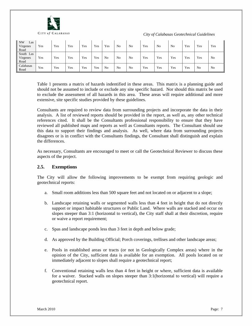
Table 1: Hazard Matrix Based on Previous Consultant Reports
Location/ Hazard
Expansive Soil
Hydro- consol
Artifical Fill
Corro-sivity
High GW
Land- slides
Rock- fall Fault Ground-
shaking Lique-faction
Lateral Spread
Seismic Settle
Ground Lurching
Earth-quake Induced Landslide
Calabasas Highlands Yes Yes Yes Yes Yes Yes Yes No Yes No No Yes Yes Yes
Topanga Canyon Yes Yes Yes Yes Yes Yes Yes No Yes Yes No Yes Yes Yes
Old Topanga Canyon
Yes Yes Yes Yes Yes Yes Yes No Yes Yes No Yes Yes Yes
City of Calabasas Geotechnical Guidelines
March 2010 Page: 7
NW Las Virgenes Road
Yes Yes Yes Yes Yes Yes No No Yes No No Yes Yes Yes
South Las Virgenes Road
Yes Yes Yes Yes Yes No No No Yes Yes Yes Yes Yes No
Calabasas Road Yes Yes Yes Yes Yes No No No Yes Yes Yes Yes No No
Table 1 presents a matrix of hazards indentified in these areas. This matrix is a planning guide and should not be assumed to include or exclude any site specific hazard. Nor should this matrix be used to exclude the assessment of all hazards in this area. These areas will require additional and more extensive, site specific studies provided by these guidelines.
Consultants are required to review data from surrounding projects and incorporate the data in their analysis. A list of reviewed reports should be provided in the report, as well as, any other technical references cited. It shall be the Consultants professional responsibility to ensure that they have reviewed all published maps and reports as well as Consultants reports. The Consultant should use this data to support their findings and analysis. As well, where data from surrounding projects disagrees or is in conflict with the Consultants findings, the Consultant shall distinguish and explain the differences.
As necessary, Consultants are encouraged to meet or call the Geotechnical Reviewer to discuss these aspects of the project.
2.5. Exemptions
The City will allow the following improvements to be exempt from requiring geologic and geotechnical reports:
a. Small room additions less than 500 square feet and not located on or adjacent to a slope;
b. Landscape retaining walls or segmented walls less than 4 feet in height that do not directly support or impact habitable structures or Public Land. Where walls are stacked and occur on slopes steeper than 3:1 (horizontal to vertical), the City staff shall at their discretion, require or waive a report requirement;
c. Spas and landscape ponds less than 3 feet in depth and below grade;
d. As approved by the Building Official; Porch coverings, trellises and other landscape areas;
e. Pools in established areas or tracts (or not in Geologically Complex areas) where in the
opinion of the City, sufficient data is available for an exemption. All pools located on or immediately adjacent to slopes shall require a geotechnical report;
f. Conventional retaining walls less than 4 feet in height or where, sufficient data is available
for a waiver. Stacked walls on slopes steeper than 3:1(horizontal to vertical) will require a geotechnical report.

City of Calabasas Geotechnical Guidelines
March 2010 Page: 8
This is only applicable if the site is in an area that is not designated as "geologically complex" as determined by the City staff and listed in Section 2.4.
2.6. Submittal Requirements
Submittal of all geologic and geotechnical reports shall be made to Public Works for review. The submittal shall include but not be limited to:
1. Three copies of engineering geologic and/or geotechnical engineering reports that are wet stamped and manually signed by the project Consultants in accordance with Section 1.5.;
2. One (1) CD with the completed report and any maps included in PDF format;
3. Three sets of dated Architectural, Foundation, and Grading and Drainage Plans. Landscape
plans should be included as necessary. In areas of flooding or within FEMA’s FIRM zones should include hydraulic calculations and flood limits and supporting calculations;
4. Fees pursuant to Public Works Department.
The geotechnical reviewers will review the project, which may include a site visit within 2 to 4 weeks. Complex sites, multi-family and commercial developments, and subdivisions, may require longer review periods.
The review process will evaluate the reports for completeness and conformance to standards of practice and to City, County, and State Code requirements. Letters issued during the planning stage will include items to be addressed prior to building/grading plan check stage, as most reports include recommendations for building/grading plan check items.
3.0. GUIDELINES
The guidelines contained in the following sections have been prepared for the purpose of providing general format and minimum requirements for analysis and report preparation. The most common factors that contribute to geologic/geotechnical review concerns are typically related to the following areas:
a) Omission of data;
b) Incorrect modeling and resulting analysis;
c) Lack of supporting data;
d) Inconsistency with surrounding or previous data;
e) Failure to provide supporting data for the proposed findings (conclusionary findings);
f) Unclear or incomplete maps, cross sections and analysis;
City of Calabasas Geotechnical Guidelines
March 2010 Page: 9
g) Insufficient testing and exploration.
In all cases, the data presented in the report should substantiate the conclusions and recommendations. The guidelines have been prepared to serve only as a reference during both preparation and review to assure the processing of permits in an expeditious manner. Furthermore, subjects addressed in these guidelines are not meant to be all inclusive, but to include the majority of project areas in the City of Calabasas.
The Project Engineer and Geologist shall provide the City of Calabasas with all the available technical data and first-hand information of the site geologic and geotechnical conditions. These guidelines provide a minimum requirement for the data necessary for a project. The City considers it the professional responsibility of the professionals to perform all work necessary to prepare a thorough and comprehensive study for the analysis and design of the project.
3.1. Types of Projects
3.1.1. New Residential and Commercial Construction
These projects include new single-family residences, multi-family structures, commercial/industrial buildings, detached guest houses, and detached studios (those considered habitable by Code). Projects involving the re-development of existing sites are considered new construction (example: demolish single-family residence and construct new residence).
Comprehensive engineering geologic and geotechnical engineering reports are required that conform to the City’s Guidelines and all applicable Codes and Ordinances.
3.1.2. Remodels
Projects include interior remodels of existing structures, including conversions of existing buildings from one occupancy to another in accordance with the current Building Code. No review by the City Geotechnical Consultants will be required if no new foundations are part of the remodel or conversion. Remodels requiring an enlargement of the private sewage treatment system may require some level of review, determined by the City on a case-by-case basis. Geotechnical recommendations addressing modifications to existing foundations, new foundations, underpinning foundation elements, floor slabs, and upgrades to the current Building Code may be required on a case-by-case basis.
3.1.3. Additions to Existing Structures
Projects may include first-floor, second-floor, and two-story additions to existing single-family residences, multi-family structures, commercial structures, detached garages, detached guest houses, detached studios, detached pool houses/cabanas, and barns. Requirements for geotechnical engineering and engineering geologic reports will vary depending on the location of the addition compared to the existing structure, the addition, for example encroaching toward a slope or geotechnical hazard, whether the additions provide additional loading on existing foundations, and whether the addition is a second-story addition with no increase in footprint square footage to the existing structure.
3.1.4. Swimming Pools/Spas
City of Calabasas Geotechnical Guidelines
March 2010 Page: 10
The Building Code defines a swimming pool as, “...any structure intended for swimming or recreational bathing that contains water over 24 inches deep.” This includes in-ground, above-ground, and on-ground swimming pools; hot tubs; portable and non-portable spas; and fixed in-place wading pools.”
Swimming pools on hillsides or geologic complex areas will require a geologic and geotechnical report. Swimming pools and spas in established areas, as deemed by the Building Official or Reviewing Geotechnical Consultant, may not require geologic and geotechnical reports. In some cases, a reduced study that involves a professional review of previous reports and proposed plans with accompanying recommendations may be required.
3.1.5. Repairs to Existing Structures/Remedial Grading
These Projects include repairs to existing structures and properties damaged by landslide movement, liquefaction, earthquakes, flooding, fires, wood rot and fungi, and other natural disasters. Geotechnical engineering and engineering geological reports may be required, on a case-by-case basis in accordance with the current Building Codes and Ordinances. Reports should address causes and extent of damage, as well as repair alternatives in accordance with standards of practice and the City’s Guidelines. Recordation of an “Assumption of Risk and Release” for geotechnical hazards may be required prior to permit issuance where special circumstances exist and granted by the City. In general, the City will not accept “Assumption of Risk and Release” for landslides.
Whenever a repair (corrective work performed to protect existing structures) is required, it shall be designed to meet all existing standards within these guidelines unless specific exemption is granted by the City Engineer (e.g., in the event of an emergency).
3.2. Types of Studies/Reports
Geotechnical engineering and engineering geologic reports may be prepared by geotechnical consultants for a variety of scopes of services depending on the proposed development project and the stage of review (planning or building/grading plan check). Each report submitted should clearly indicate the purpose and scope of the study as well as the proposed development as discussed in the previous section.
3.2.1. Feasibility/Preliminary Design/Design-Level Reports
Feasibility studies, including EIR documents, shall focus on feasibility of the proposed development and potential impacts that relate the proposed land uses with the geologic environment. Specific mitigation measures are not required at this stage. It must be demonstrated, however, that all potential geotechnical hazards that may affect the proposed development can be mitigated.
Preliminary Design Reports address a project at the stage where general development plans have been prepared, although final or specific development plans may not be available. Preliminary design reports discuss the feasibility of site development for a particular development concept and provide general recommendations for site development. Both Feasibility Reports and Preliminary Geotechnical Reports are often prepared in advance of detailed building or grading plans, but should provide recommendations for those plans. Therefore, a supplemental Building/Grading Plan Review Report may be required to insure that the actual building and grading plans comply with the preliminary geotechnical recommendations.
City of Calabasas Geotechnical Guidelines
March 2010 Page: 11
Design-level reports provide site-specific design recommendations related to a specific development concept but may precede development of grading and/or building plans. Studies at this stage shall relate to specific design recommendations and mitigation of engineering and geologic hazards as they relate to grading and building of the proposed development. For many projects the preliminary design report is intended by the applicant to serve also as the feasibility design report and the design-level report. In such cases, minor or major changes can occur in development plans between the time the geotechnical report is prepared and time of submittal for a permit. Additional geotechnical work may be required, and a Building/Grading Plan Review report may be required.
When the current development plan differs significantly from that which the geotechnical report was prepared, but in the opinion of the Geotechnical Consultant additional geotechnical work is not required, a letter would be required when the plans are submitted for review stating the Consultant has reviewed the current plans and that the recommendations in the geotechnical report are still applicable, or provide revised recommendations as appropriate.
Exemption: The City Engineer may exempt certain projects from report requirements. Exempted projects, however, must not be located within geologically complex areas, Seismic Hazard Zones or Fault Hazard Zones.
3.2.2. Seismic Hazard Evaluation Reports
Geotechnical reports for sites within a Seismic Hazard Zone, as identified in accordance with the Seismic Hazards Mapping Act, Public Resources Code, Division 2, chapter 7.8, shall include a section evaluating seismic hazards, or a separate report shall be provided meeting all requirements set forth in said Act. Seismic hazards should be addressed in accordance with the Seismic Hazards Mapping Act. Pertinent references include:
Recommended Criteria for Delineating Seismic Hazard Zones in California; CDMG, Revised 1999, Special Publication 118); Fault-Rupture Hazard Zones in California; CDMG, 2007, Special Publication 42; Probabilistic Seismic Hazard Assessment for the State of California; CDMG, 1996, Open-File Report 96-08; Guidelines for Engineering Geologic Reports; State of California, Board for Geologists and Geophysicists, 1998; Guidelines for Earthquake and/or Fault Hazard Reports; State of California, Board for Geologists and Geophysicists, 1998; Guidelines for Groundwater Investigation Reports; State of California, Board for Geologists and Geophysicists, 1998; Guidelines for Geophysical Reports for Environmental and Engineering Geology; State of California, Board for Geologists and Geophysicists, 1998; Alquist-Priolo Earthquake Fault Zoning Act; CGS, 2007;

City of Calabasas Geotechnical Guidelines
March 2010 Page: 12
Seismic Hazards Mapping Act; CGS, 2007; Faults and Earthquakes in California; CGS, 2003, Note 31; Guidelines for Evaluating the Hazard of Surface Fault Rupture; CGS, 2002, Note 49; Guidelines for Preparing Geologic Reports for Regional-Scale Environmental and Resource Management Planning; CGS, 2001, Note 52;
Seismic Hazards Maps, published by the California Geological Survey (previously California Division of Mines and Geology), and the United States Geologic Survey (U.S.G.S.) include the following published reports/maps that pertain specifically to Calabasas and should be included in any study:
1. California Division of Mines and Geology, 2001, Seismic Hazard Evaluation of the Malibu Beach 7.5-Minute Quadrangle, Los Angeles County, California: California Division of Mines and Geology Open-File Report, scale 1:24,000.
2. California Division of Mines and Geology, 1998, Seismic Hazard Evaluation of the
Canoga Park 7.5-Minute Quadrangle, Los Angeles County, California: California Division of Mines and Geology Open-File Report 97-14, scale 1:24,000.
3. California Division of Mines and Geology, 1998, Seismic Hazard Evaluation of the
Calabasas 7.5-Minute Quadrangle, Los Angeles and Ventura Counties, California: California Division of Mines and Geology Open-File Report 97-13, scale 1:24,000.
4. California Geological Survey; 2001; Seismic Hazard Zone Report for the Malibu
Beach 7.5 Minute Quadrangle, Los Angeles County, California; Seismic Hazard Zone Report 050.
5. California Geological Survey; 2001; Seismic Hazard Zone Report for the Canoga
Park 7.5 Minute Quadrangle, Los Angeles County, California; Seismic Hazard Zone Report 080.
6. California Geological Survey; 1997; Seismic Hazard Zone Report for the Calabasas
7.5 Minute Quadrangle, Los Angeles and Ventura Counties, California; Seismic Hazard Zone Report 060.
These maps and reports are available for review and reproduction at the City or may be reproduced by a Bonded Blueprinting service.
3.2.3. Fault Rupture Hazard Reports
The State of California Geological Survey (CGS), formerly Division of Mines and Geology (CDMG), has not zoned any areas of Calabasas in an Earthquake Fault Zone in accordance with the Alquist-Priolo Earthquake Fault Zoning Act of 1972, Public Resources Code, Division 2, chapter 7.5 (1972, Ch. 1354; Amended by Stats. 1975, Ch. 61. Effective May 4, 1975; Amend by Stats. 1993,

City of Calabasas Geotechnical Guidelines
March 2010 Page: 13
Ch. 197.). All studies will strictly adhere to the State of California Public Resource Code, and no specifications of this Manual will modify or further restrict the State requirements.
The City’s requirements regarding fault rupture hazard studies are outlined in Section 5.1.1. Requirements depend on the location of the proposed development project in the City, and the scope of the project. Special studies may be arranged between the applicant’s geotechnical consultants and City Geologist on a case-by-case basis. One extra copy of the geotechnical report should be submitted for filing with the State Geologist (CDMG) within 30 days of acceptance. (SP 42, page 26 3603F).
3.2.4. Geologic Reconnaissance Reports
These reports include a review of the City’s files on the site and adjacent properties, regional geologic and geotechnical maps, pertinent pairs of stereographic aerial photographs, and a site reconnaissance. No subsurface exploration is usually required, but the report must be prepared by and signed by a state-certified engineering geologist.
3.2.5. Geotechnical Engineering Reconnaissance Reports
These reports include a review of the City’s files on the site and adjacent properties, a discussion of existing geotechnical conditions on the site, an evaluation of proposed geotechnical work on the site, and a site reconnaissance. The engineer should address any potential geotechnically related hazard and provide recommendations as to the need for any additional geotechnical data and analyses. Subsurface exploration is usually not required, but this report must be prepared by and signed by a state-licensed professional engineer practicing in geotechnical engineering or a state-registered geotechnical engineer.
3.2.6. Building/Grading-Plan Review Reports
As discussed in Section 2.3., these reports entail the review of Building or Grading plans for conformance with the site-specific geotechnical engineering recommendations. Grading and building plans reviewed and deemed acceptable for construction by the Project Geotechnical Consultants shall indicate that the plans conform to all the recommendations made in the applicable reports. Reports shall be signed and wet-stamped by the Project Geotechnical Engineer and Engineering Geologist, as appropriate.
If the latest geotechnical report is based on the current building and grading plans or previous plans with only minor revisions, a review, signing, and stamping of the current building and grading plans will be acceptable without the submission of a separate new geotechnical review report. Specific requirements are discussed in Section 2.3., and later in these guidelines, however, typical issues which should be addressed are:
a. Specific grading recommendations (in conformance with the current building Code); b. Specific surface and subsurface drainage recommendations;
c. Slope stability mitigation;
d. Settlement mitigation;
City of Calabasas Geotechnical Guidelines
March 2010 Page: 14
e. Liquefaction and lateral spreading mitigation;
f. Seismic settlement mitigation;
g. High groundwater (CBC 2007, Section 1802.2.3)
h. Expansive soil or hydroconsolidation settlement (CBC 2007, Section 1802.2.2 and 1802.3.2);
i. Existing uncompacted fill mitigation (CBC 2007, Section 1802.2.1);
j. Construction stabilization and shoring plans and specifications;
k. Foundation recommendations;
l. Retaining wall recommendations;
m. Swimming pool design recommendations; n. Flatwork recommendations;
o. On-Site Sewage Disposal System impacts (effluent direction, groundwater regional and local
mounding and water quality) and recommendations.
3.2.7. Update Reports
Update reports from geotechnical consultants may be required when:
a) The scope of the project changes;
b) Professional registration of consultants expires (existing reports);
c) Site conditions change, including above normal rainfall;
d) Previous reports are sufficiently old so as to be outdated with regard to industry standards of practice or building codes;
e) At the discretion of the City Engineer;
f) Report is older than 2 years, or older than the report indicates validity.
The report shall describe the currently proposed development; include a site reconnaissance, plan review, and reference prior reports. The update report shall state if all recommendations of the prior report(s) are applicable, or provide revised recommendations, as appropriate.
3.2.8. As-Built Compaction Reports
These reports should be prepared upon completion of grading of a site by a state-licensed professional engineer practicing in geotechnical engineering or a state-licensed geotechnical engineer. City
City of Calabasas Geotechnical Guidelines
March 2010 Page: 15
geotechnical staff or the Building and Safety Department will determine whether a site requires the applicant’s geotechnical consultant to prepare this report, depending on the scope of grading. City geotechnical staff will include this requirement as a comment on their building or grading plan permits. Reports shall comply with the City’s Building Codes.
As-built compaction reports shall include, but not be limited to, the following:
a. Results of all in-place density tests and maximum density determinations;
b. Testing methodology and standards including the use of sand cones to substantiate nuclear gauge tests (1 sand cone for every 10 nuclear gauge tests);
c. Sieve and compaction and other index tests to substantiate compaction tests including moving
curves and import soils as necessary;
d. Geologic map of all geologic data collected during grading;
e. Results of all expansion index tests;
f. Deep (pile) foundation observations and documentation;
g. Results of revised as-built slope stability analyses (if warranted);
h. Documentation of all footing inspections and bottom approvals;
i. Results of all settlement monitoring;
j. Results of all R-value tests (if warranted);
k. A map depicting the limits of grading, limits of all bottom excavations, locations of all density tests, removal bottom locations and elevations, keyway bottom locations and elevations, all keyway, cleanout, and swimming pool subdrain locations and flow line elevations, and all retaining wall backdrain locations and flow line elevations;
l. Location and elevation of all subdrain outlets;
m. Specific documentation, photographs, maps and discussions where special mitigation
procedures or construction occurred i.e. buttresses, shear keys, etc.
The dry density and moisture content data shall be presented in a form to show in-place values along with the associated laboratory maximum dry densities and optimum moisture contents. All failed tests shall be clearly marked along with the associated re-tests. The Project Geotechnical Engineer and Project Engineering Geologist shall make any comments as appropriate and sign the “as-built” grading plans.
3.2.9. As-Built Engineering Geologic Reports
These reports should be prepared upon completion of grading by a State of California, Certified Engineering Geologist. City Geotechnical Consultant will determine whether a site requires the
City of Calabasas Geotechnical Guidelines
March 2010 Page: 16
applicant’s engineering geologic consultant to prepare this report, depending on the scope of grading and geologic conditions exposed. The engineering geologic report shall discuss geologic conditions exposed during grading, provide additional recommendations for the proposed development (along with the geotechnical engineering consultant, if necessary) if unusual or unexpected conditions are encountered, and include a map depicting the geologic conditions exposed during grading.
3.2.10. Final Development Reports
Final development reports will be prepared at the completion of development prior to a granting of Certificate of Occupancy for review and approval by Public Works. This report will provide but not limited to:
a. Any additional grading and compaction testing performed subsequent to the Rough Grade Report;
b. All utility trench back fill compaction testing and lab results; c. All structural pavement soil subgrade and aggregate base rock compaction testing; d. All slab subgrade compaction testing, capillary break, vapor barrier placement and sand
placement; e. All foundation observations and approvals. Where deep foundations are installed, downhole
logs shall be provided where conditioned by the City. An As Built map shall be provided to demonstrate pile locations and depth shall be provided;
f. Expansion Index tests; g. Any other structures or other improvements; h. Any exclusions or testing that was not completed or found in conformance with the
recommendations of the project consultants.
3.3. Change of Consultant Letters
Written notification will be required if a change in geotechnical consultants occurs after the review process has been initiated or ownership of the property has changed. The letter must state that the new consultants have reviewed the work by the previous consultants, concur with their recommendations and conclusions, and agree to assume responsibility as geotechnical consultants of record from this point forward. In addition, a Letter of Release shall be provided by the previous consultants, unless extenuating circumstances exist and a waiver is granted by the City.
If the new Consultant(s) do not concur with the previous consultants’ conclusions and recommendations, additional subsurface exploration, testing, and analyses may be warranted. Two copies of the letter that are wet stamped and manually signed by the new project geotechnical consultants shall be submitted to City Geotechnical Consultant for review. No permits shall be issued for a project, and all previously permitted work shall stop until the City is officially notified of the name, address, and telephone number of the new project engineering geologist and geotechnical/civil engineer, or as otherwise approved by the City Engineer.
3.4. Level of Professional Responsibility
All work shall be performed in accordance with the State of California Business and Professional Code.
City of Calabasas Geotechnical Guidelines
March 2010 Page: 17
All reports shall be signed and wet stamped by the Geotechnical Consultants. In accordance with the California Business and Professions Code, foundation and geotechnical investigations and engineering reports must be prepared by either a registered geotechnical engineer or a licensed professional engineer with experience in geotechnical engineering. All documents that include engineering data, interpretations, or recommendations must be manually signed and wet stamped by a registered Geotechnical Engineer (GE) or a licensed Professional Engineer (PE) with experience in soils or geotechnical engineering, including license number and expiration date. Certain projects, including essential facilities and schools, require a licensed geotechnical engineer (GE).
4.0. GUIDELINES FOR CONTENT OF GEOTECHNICAL REPORTS
Geotechnical work includes both engineering geology and geotechnical engineering. This section provides specific guidelines related to report content for various aspects of most geotechnical reports.
4.1. Geotechnical Reference Standards
In general, all geotechnical and geologic reports shall comply with the most recent versions of appropriate standards, codes, and professional guidelines. The citations for some of the appropriate references are included in Appendix A.
4.2. Report Organization
All geotechnical reports shall include the following items, as appropriate for each project. Project geotechnical consultants determine the specific report format. The reports should include but not limited to:
a) Purpose;
b) Scope of Work;
c) Site Description, including access and level of research;
d) Existing Site Conditions: Site Location; Site Topography; Site Drainage; Existing Structures & Improvements; Adjacent Properties, and Slopes;
e) Proposed Development – Reports shall contain a description of the proposed development.
The proposed developments shall be clearly shown on plans and cross-sections;
f) Previous Work at the site and surrounding areas;
g) Subsurface and Field Exploration – Describe the field exploration, methods of excavation, methods and type of sampling, provide exploration logs, and include dates of exploration. All Geologic data, stratigraphy and structure should be plotted on Maps and Cross Sections;
h) Geotechnical and Chemical Testing – Describe the laboratory testing procedures and test
results, and provide graphical laboratory test sheets;
City of Calabasas Geotechnical Guidelines
March 2010 Page: 18
i) Geotechnical Analyses and Findings – Describe the analyses performed and the technical findings. At a minimum, the geotechnical report shall specifically address each of the following potential hazards:
i. Seismic hazards, including fault rupture, groundshaking, liquefaction, lateral spread, seismic settlement, earthquake induced landslides, ground lurching, seiches, and other potential hazards;
ii. Existing fill or unsuitable soils;
iii. Daylighted bedding or fill wedges and surcharges;
iv. Expansive soil or rock;
v. Groundwater (CBC 2007, Section 1802.2.3);
vi. Hydroconsolidation potential;
vii. Slope stability and slope instability potential (debris flows, rockfall, creep, etc.);
viii. Slope deformation;
ix. Temporary excavations and shoring;
x. Rippability or shallow bedrock;
xi. Settlement and subsidence;
xii. Corrosion and Sulfate;
xiii. Adverse impacts of sewage effluent;
xiv. Soil erosion and special considerations for storm water management.
j) Summary and Conclusions including a County of Los Angeles Section 111 Statement;
k) Recommendations;
l) Figures – The following figures shall be included with each report:
i. Site Location Map;
ii. Regional Geologic Map;
iii. Seismic Hazard Map;
iv. Geologic or Geotechnical Map (40-scale or less) within project development plans as base map;
v. Geologic or Geotechnical Cross Sections.
m) References including all surrounding properties;
n) Appendices including all supporting engineering calculations.
4.3. Maps, Plans, and Cross Sections
City of Calabasas Geotechnical Guidelines
March 2010 Page: 19
4.3.1. Site Location Map
A map with a north arrow and scale shall be provided for all projects that show the site and surrounding area, encompassing a large enough area to easily and accurately locate the site on regional maps.
4.3.2. Regional Geologic Hazard Maps
Regional geologic hazard maps depict conditions that extend beyond the site geologic map. Regional geologic hazard maps may be used to locate and generate geologic cross-sections that extend offsite, especially where sites encroach into hillside areas. Copies of seismic hazard maps showing the site location are required for all sites located inside a Seismic Hazard. Copies of Earthquake Fault Hazard Zone maps showing site location are required for all sites located within an Earthquake Fault Hazard Zone.
4.3.3. Site Geotechnical/Geologic Maps
A site geotechnical map depicting the site and immediate area surrounding the site is required for all projects. The following shall be depicted on the site specific geotechnical map:
a. Existing onsite structures and closely located offsite structures that may be potentially located within the zone of influence with the proposed development;
b. Proposed improvements;
c. Limits of earth units across the site and depth to bedrock as relevant;
d. All landslides, slumps, and other pertinent geologic features;
e. All exploratory borings and trenches/test pits known to exist on the site;
f. All geologic cross-section location lines;
g. Geologic data from subsurface excavations and surface mapping (where applicable);
h. An explanation that clearly defines all contacts, symbols, lithologic units, and other relevant
data shown on the map. The site-specific geologic/geotechnical map for projects with significant grading shall use an accurate topographic base map and a scale sufficient to clearly depict the details of the proposed development and geologic and soil conditions. The base map shall clearly indicate the map scale, true north, and who prepared the map;
i. Graphical scale;
j. Company name;
k. Project name and address;
City of Calabasas Geotechnical Guidelines
March 2010 Page: 20
l. Clearly depict all drafting and legible writing. If the text is hand written, as a general rule the text should be 0.1 inch and 0.06 inches for computer text. Smaller sizes will be accepted where clearly legible.
Additional data may be requested as necessary to demonstrate the necessary analysis for the project.
4.3.4. Geotechnical Cross Sections
Cross sections are required to depict interpreted geologic conditions underlying the site. Cross-sections shall be drawn where natural, cut, or fill slope heights or basement, retaining wall, or temporary/permanent excavation exceeds 6 feet, or when an excavation will removal lateral adjacent support for the adjacent property.
Cross sections shall clearly show site boundary locations, location and size of all existing and proposed structures, locations of all exploratory excavations, contacts between earth units, intersections with other cross-sections, and the extent of proposed grading and over-excavations.
Geologic data shall be reasonably interpreted throughout the length of the section. Worst-case geologic and soil conditions (the most adverse conditions that can reasonably be expected given the field conditions and site history) must be illustrated.
Historic high groundwater levels, as well as, current groundwater levels must also be shown on the cross-sections. Geologic cross-sections shall extend from the top to the bottom of slopes, without regard for property lines. If offsite geologic conditions could influence a site, cross-sections shall be drawn to illustrate those conditions.
Cross-section(s) shall be constructed across the site which depict the proposed seepage pits or leach fields, anticipated paths of effluent, recommended capping depths for seepage pits (if applicable), areas where mounded groundwater would occur, and underlying geologic and groundwater conditions.
4.4. Signatures
All reports must be wet signed by appropriately registered professionals. Reports in hillside areas and all reports that contain geologic interpretations or subsurface exploration of faulting must be signed by a certified engineering geologist.
These requirements supersede the requirements of the State of California (Section 3.4.)
4.5. Technical Support Documentation
All findings, conclusions, and recommendations shall be substantiated by data included within the report. Applicable regional published (and unpublished, if available) geologic reports, maps, aerial photographs, and other technical documents (e.g., geotechnical reports on file with the City) for the immediate area or subject property shall be reviewed and referenced. As a minimum, research of all public (jurisdictional) files for the surrounding area shall be performed.

City of Calabasas Geotechnical Guidelines
March 2010 Page: 21
Engineering recommendations and design values shall be supported with the appropriate engineering analysis, referenced from acceptable, published sources or text. Where engineering judgment is necessary, appropriate discussion and thorough explanation should be provided.
Site-specific field and/or laboratory data and appropriate analyses shall substantiate all recommendations and conclusions. Where professional judgment is utilized to augment the data and analyses, a technical rationale shall be clearly discussed. Potentially hazardous geotechnical processes and site conditions must be disclosed.
4.5.1. Previous Geotechnical Data
All geotechnical data previously collected for the subject site shall be included and properly referenced in the geotechnical report. Consultants shall present previous data and discuss known geotechnical investigations for the site and surrounding areas. Copies of previous reports may be required by the City where necessary.
4.5.2. Identification and Mitigation of Risks
The Geotechnical Consultant shall discuss and evaluate each potential geologic/geotechnical hazard and either state that such hazard is not present or provide appropriate mitigation measures, with supporting data to substantiate the measures. In situations where such hazards are not identified at the site, the report shall include statements to that effect and provide support for making such statements.
A lack of discussion and evaluation of a particular hazard will not be interpreted by the Reviewers as a presumption that such hazard does not exist, even if in the opinion of the Reviewer a particular hazard is not present at a site.
It is neither the intent nor responsibility of the Reviewer to infer conclusions that a particular hazard is not present. The Geotechnical Consultant must provide appropriate statements for each of the typical geotechnical hazards, and geotechnical reports without such statements will not be accepted.
Although recommendations for mitigating identified risks shall be provided, the risks associated with some hazards cannot be totally eliminated. The risk, however, shall be mitigated to a level of preventing structural collapse and loss of life. It is an essential element of the report that it identifies and discusses the risk for the property owner. Acceptable mitigation methods can include recommendations related to site improvement, site drainage, maintenance practices, and structural design.
4.5.3. References
Referenced materials shall include:
a) Literature, reports, previous site work, unpublished consultants reports and records cited and reviewed;
b) Aerial photographs or images interpreted, listing the type, date, scale, source, and index
numbers, etc.;
c) Compiled data, maps, or plates included or referenced;
City of Calabasas Geotechnical Guidelines
March 2010 Page: 22
d) Other sources of information, including well records, personal communications, or other data
sources that were used to form the opinions and recommendations of the report.
4.5.4. Geotechnical Exploration Logs
Geotechnical reports shall include logs of all geotechnical explorations (boring, test pit, and trench logs) on the site, including cone penetrometer soundings and data, and results of other in-situ testing. Each exploration point shall be identified with coordinates (longitude and latitude) and elevation. All work shall be in accordance with CBC 2007, Section 1802.4 thru 1802.5.
For trenches, the end of each straight line segment shall be identified. Information that shall be shown on exploration logs or included within the report text includes, but not limited to:
a. Names of the responsible field personnel;
b. Dates of exploration;
c. Exploration method/drill rig type;
d. Boring/trench location and elevation, including decimal longitude and latitude coordinates (if available);
e. Groundwater observations (indicate time of measurement);
f. Drilling method (e.g., hollow-stem auger, bucket auger, wet rotary);
g. Sample Depths;
h. Hammer (e.g., safety hammer) and sampler (e.g., SPT with or without liners, modified
California sampler) details and method of hammer drop (e.g., automatic, cathead and rope with number of wraps) to convert measured sampler blow counts to an equivalent blow count associated with SPT with a delivered energy of 60% (N60);
i. Detail of Kelly bar weight and drop height (if applicable);
j. Name of geologist or engineer responsible for logging;
k. Description of excavation backfill;
l. Results of field tests (e.g. pocket penetrometer, vane shear);
m. Results of soil density and moisture tests (unless shown in an alternative manner);
4.5.5. Cone Penetrometer Data
If Cone penetrometer (CPT) sounding data is included, profiles of cone tip resistance, either sleeve resistance or friction ratio, and porewater pressure, when available, shall be provided. Interpreted
City of Calabasas Geotechnical Guidelines
March 2010 Page: 23
results, such as soil type, estimated relative density, friction angle, or undrained shear strength of the soil, and equivalent sample blow counts shall be included.
The methodology and relevance for interpreting the CPT data shall be cited. The type and size of cone and penetration rate shall be documented. CPT data shall be substantiated by at least one adjacent soil boring with samples analyzed with sufficient laboratory tests to compare to interpreted CPT results.
CPT is considered an acceptable and useful tool for characterizing subsurface conditions. In general, at least one drill hole with corresponding standard penetration rates will be required for calibration for the CPT soundings (DMG 117), unless previously agreed upon by the City Reviewer.
4.5.6. Plans & Cross-Sections
Where a grading permit is required, the geotechnical report shall include a proposed grading plan showing existing and proposed contours from which an appropriate number of cross-sections shall be drawn. All maps and cross sections shall be drawn using standard geologic nomenclature as setforth from the USGS and the standard of practice.
4.5.7. Computer Programs and Analyses
Engineering analyses performed by computer programs shall include a description of the computer program; the applicability of the program for analysis; reference information regarding the software used; and include the printouts of applicable input and output files. Where necessary, the City and their reviewers reserve the right to request electronic input files.
Where spreadsheets are utilized, a specific reference shall be provided to correlate equations. Where the City Reviewer cannot clearly discern or independently verify the results, the Consultant shall provide the reference and either a copy of the spreadsheet and/or supporting hand calculations.
5.0. ENGINEERING GEOLOGIC GUIDELINES
5.1. Seismic Hazard Evaluation
Geotechnical reports shall address all potential seismically induced hazards that may affect the subject property and proposed development, and provide adequate mitigation measures (if necessary). Seismic hazards shall be evaluated in full conformance with:
1. “Guidelines for Evaluating and Mitigating Seismic Hazards in California” (CDMG, 1997, Special Publication 117);
2. “Recommended Procedures for Implementation of DMG Special Publication 117, Guidelines
for Analyzing and Mitigating Liquefaction in California” (SCEC, 1999).
3. “Recommended Procedures for Implementation of DMG Special Publication 117, Guidelines for Analyzing and Mitigating Landslide Hazards in California” (SCEC, 2003).
In addition, extensive publications exist in peer reviewed literature that should be cited as necessary for the project. It should be recognized that this field is constantly changing and it is the Consultants

City of Calabasas Geotechnical Guidelines
March 2010 Page: 24
responsibility to remain current on the prevailing literature and analysis methodology. This should include using current attenuation relationships and other analyses.
Where appropriate for quantitative hazard analyses (e.g., liquefaction and seismically induced settlement), ground acceleration values shall be represented by the peak ground acceleration for both unweighted and weighted magnitude associated with a 10% probability of exceedance in 50 years (475 year return interval). Design accelerations and the probability of occurrence shall be discussed and justified in the report. Data shall be based on earthquake events on faults that may affect the site (i.e., faults within at least 50 miles of the site) using the CDMG fault database. Any deviations from the CDMG fault database shall be described and justified.
In lieu of a site specific study, ground accelerations can be based on CDMG seismic hazard evaluation report maps. For all projects within the City of Calabasas, geotechnical reports shall include site-specific assessments of seismic hazards for each project. The degree of the assessment may vary with the project type, as explained in the following paragraphs. The fact that a project site is not located within a seismic hazard zone does not obviate the requirement that these hazards be discussed in the report.
All engineering geologic and geotechnical engineering reports must contain, at a minimum, a site-specific description of, but not limited to, the following:
a. Regional tectonic setting;
b. Location of major fault traces and local known faults near the site based on a review of surrounding geology files, regional maps, CDMG geologic and seismic hazards studies, and stereo pairs of aerial photographs. Distances from the site to faults within two miles of the site shall be based on appropriate geologic maps and not on fault locations determined by computer programs using the CDMG fault database;
c. Fault-rupture hazard evaluation;
d. Significant historic earthquakes including epicenter distances, earthquake magnitudes, and
estimated intensity at the site;
e. Evaluation of ground shaking potential;
f. Potential for liquefaction;
g. Potential for lurching and topographic-related site effects;
h. Potential for lateral spreading;
i. Potential for seismically-induced settlement;
j. Potential for earthquake-induced landsliding in hillside areas and any effects for potential run out zones (i.e. rockfall, debris flow);
k. Seiche or tsunami potential;
City of Calabasas Geotechnical Guidelines
March 2010 Page: 25
l. Slope deformation potential;
m. Quantitative evaluation of ground shaking potential, including an evaluation of peak and repeatable high ground accelerations, duration of strong shaking, and the effects of ground motion. The effects of such an earthquake on existing or proposed structures, underlying earth materials, and slope stability shall be provided. In accordance with the Seismic Hazards Mapping Act of 1990 (Sections 2690 through 2699 of the Public Resources Code).
Seismic Hazard Evaluation reports to accompany many of the maps have been prepared by the CDMG and are available from the City or in the CDMG's website.
5.1.1. Fault Rupture Evaluation
Fault trenching will be required across habitable building sites, including single-family residences, multi-family residential units, guesthouses, studios, and commercial buildings, to evaluate fault rupture hazard if the site lies:
1. Within an Alquist-Priolo Fault Zone as defined by the CDMG maps; or,
2. Within 500 feet of faults mapped by the CDMG.
Engineering geologists are required to trench perpendicular to the anticipated direction of faults traversing the area. The trenches shall be extended deep enough to substantiate findings related to the age of faulting. This may also require radioactive age dating. It will be the Consultants responsibility to extend the fault trench to sufficient depth, and the fault trenches will be reviewed in the field by the City Consultants. Remedial grading plans may be required for excavations.
Engineering geologic consultants may utilize existing trench data and exposures on adjacent properties east or west of the subject site in lieu of trenching. The City will review these on a case-by-case basis. Where bedrock is available in the near surface, trenches shall be a minimum depth of 5 feet into bedrock. If sufficient exposures are not obtained, deeper excavations will be required.
Detailed, illustrated logs of the trenches shall be provided, along with descriptions of all earth units and geologic conditions. A discussion of the findings shall be provided, including conclusions regarding activity of any faults exposed in the excavations. Other forms of site-specific fault rupture hazard investigations are acceptable provided they are conclusive (based on mutual agreement in writing between project engineering geologist and the City).
Prior to any fault trenches, the Consultant should contact the City. The City may require the Applicant to provide a deposit for the City Reviewer to observe and document the fault trench. The City reserves the right to refuse to accept the data and findings if the City does not observe and verify the fault trench.
The Fault Rupture evaluation report shall also provide the method and manner of trench backfill and suitability. Trench backfill may require engineering in certain cases as determined by the City.
City of Calabasas Geotechnical Guidelines
March 2010 Page: 26
5.1.2. CBC Seismic Design Factors
Seismic design factors should be provided in accordance with the CBC, applicable edition, and City policy.
5.1.2a. CBC 2007
For the CBC 2007, design factors that should be discussed in the geotechnical report include but not limited to:
1. Seismic Zone (All of the City of Calabasas is located in Zone 4.);
2. Soil Type (CBC Section 1636.2 states, “when soil properties are not known in sufficient detail to determine the soil profile type, Type Sd shall be used”.). If a soil profile type other than Sd is recommended, the consultant shall discuss and support the recommendation with data;
3. Site-Fault Distance (City of Calabasas policy requires that all sites located in the City use a
Site-Fault Distance of 2 km or less, and a seismic source type of B.). The 1998 CBC static-force procedure calls for the following seismic geotechnical parameters (near-source factors) Na and Nv, which are determined from the above items and from the seismic source type (A, B, or C), which depend on the fault slip rate and maximum moment magnitude. The remaining seismic parameters Ca, Cv, Ts, and To, used in structural analyses can be computed from Na and Nv for seismic zone 4 by the structural engineer.
5.1.2b. CBC 2007
For the CBC 2007 and based on ASCE 7-05, design factors that should be discussed in the geotechnical report include but not limited to:
1. Site Longitude and Latitude;
2. Site Category Short and One Second Period (Table 1613.5.6(1) and Table 1613.5.6(2));
3. Site Class (Table 1613.5.2);
4. Short Period (0.2g)Spectral Response, Ss (Figure 1613.5(1) & 1613.5(2));
5. One Second Specteral Response, S1 (Figure 1613.5.1)*;
*Note: Per Section 1613.5.6, where S1 is greater than or equal to 0.75g, the Seismic Design Category shall be Category E.
6. Site Coefficients Fa and Fv (Table 1613.5.3(1) and 1613.5.3(2));
Values should be based on the program provided by the USGS on the following website: http://earthquake.usgs.gov/research/hazmaps/design/. The Consultant should provide a printout of the calculations from the website and any other calculations associated with the analysis.
Appendix * presents a brief summary of the analysis and procedures.
City of Calabasas Geotechnical Guidelines
March 2010 Page: 27
5.2. Field Exploration Program
Exploration methods shall be sufficient in number and depth to evaluate site conditions and acquire data to justify all conclusions and recommendations. Where applicable, the exploration program shall be coordinated between the Geotechnical Engineer and Engineering Geologist. Subsurface exploration shall be performed in areas most likely to reveal adverse geologic and soils conditions that could impact the proposed development or offsite properties due to the development on the subject site. Conditions to be evaluated include, but not limited to:
1. Exploration and documentation of all geomorphic features that suggest the presence of landslides, mud and debris flows, faults, near-surface groundwater, and other possible adverse conditions;
2. Descriptions of geologic conditions, including all contacts, layers, structure, fabric,
consistency, water content, soil types and bedrock. The descriptions should follow standard geologic and engineering protocol;
3. Descriptions and locations of springs, artesian conditions, seeps, perched zones of
groundwater, aquicludes, aquitards, and confined and unconfined aquifers. For all new construction projects, the following minimum exploration program is expected:
a. In areas with a ground surface slope less than 5:1 (horizontal to vertical) and/or areas with alluvial, colluvial and/or flood plain deposits, borings shall extend below a zone where increases in stress due to imposed loads will not negatively impact the performance of the site improvements.
The borings or exploration shall be sufficiently deep to evaluate liquefaction, lateral spreading, seismic settlement and hydroconsolidation potential. These areas should be investigated with drilling equipment that will provide Standard Penetration Rates and groundwater levels.
b. In hillside areas, the number and depth of borings and field exploration program
shall be sufficient to characterize subsurface structure and stratigraphy in order to perform and assess slope stability. The borings shall extend to a depth to ensure that all critical failure surfaces can be adequately characterized and modeled. Where the landslides or other slope instability features are encountered, the exploration shall extend to a depth to ensure that the subsurface geometries can be suitably modeled and regional stratigraphy and structure verified.
In general, the factor of safety of a potential slip surface passing beneath the maximum boring depth shall exceed 1.5 for static and 1.1 for pseudostatic or acceptable Newmark deformations. Alternatively, the borings are of suitable depth to infer and model the subsurface conditions and slope so that the factor of safety can be determined with high degree of confidence.
4. Sampling intervals shall be performed to thoroughly characterize the soil index and properties
of the soil and bedrock materials;
City of Calabasas Geotechnical Guidelines
March 2010 Page: 28
5. Qualified personnel under the direct supervision of a registered geotechnical professional shall log in detail all subsurface excavations. Geotechnical logs that include descriptions of earth units, intervals sampled with uncorrected (field) blow counts, laboratory test results (where appropriate), and logs must be presented in reports;
6. Downhole logging of geologic borings by an engineering geologist is expected in hillside
areas for the detailed evaluation of geologic conditions, unless safety issues preclude downhole logging. If downhole logging is not performed, then appropriate assumptions regarding geologic structure and lithology shall be incorporated in the project. The method of sidewall preparation for downhole or trench logging shall be described in the report;
7. For remodels (3.1.2) and additions (3.1.3), exploration shall extend to a minimum depth of
twice the width of proposed footings below the bottom of proposed footings (e.g. for a 24-inch wide footing, exploration shall extend to a minimum depth of 48 inches below the proposed footing) or a depth of five feet, whichever is greater. If conditions are present which require deeper excavations (i.e. loose fill, hydroconsolidation, etc.) deeper exploration will be required;
8. In Geologically Complex Areas, prior to any drilling, the Consultant should contact the City.
The City may require the Applicant to provide a deposit for the City Reviewer to observe and document the boring. The City reserves the right to refuse to accept the data and findings of the City Consultant unless he/she observes and verifies the boring data;
5.3. Excavation Permits
5.3.1. Permit Required
A permit shall be required for geologic/geotechnical exploratory excavations, as described below, including access road or pads created for exploratory excavation.
Exploratory excavation conducted in conjunction with the preparation of soils or other geotechnical reports that affect or disturb areas of less than ten thousand square feet on a single parcel, under the direction of soil engineers or engineering geologists, and less than fifty cubic yards, on a single parcel shall receive a permit prior to commencement of exploration. A geologic/geotechnical exploratory excavation permit application form shall be filed with the department, together with all fees, maps, and other information as required by the permit form and this section for review. The maps and required information shall include but not be limited to the following:
1. A completed geologic/geotechnical exploratory excavation permit application; 2. A written description describing the type of work to be done, which shall include, but not
be limited to, the dates for the work, any vehicles and equipment to be used, how the excavations are to be completed (hand tools or machinery), the amount, if any, proposed grading of access roads;
3. A topographic map in a drawing size sufficient in scale to clearly show the proposed
exploratory site(s).The map shall include locations of all trees being impacted by this work, access routes and paths of travel for vehicles and equipment, and any other impacted areas;
City of Calabasas Geotechnical Guidelines
March 2010 Page: 29
4. A restoration plan that provides detailed information on how the impacted areas will be
restored to their pre-excavation state. Exploratory excavations must be restored to existing conditions, unless otherwise approved by the city engineer;
5. A local storm water pollution prevention plan/wet weather erosion control plan
(SWPPP/WWECP) or, when required a storm water mitigation plan (SWMP) pursuant to Title 8 of the Municipal Code;
6. Any special reports (e.g., compaction, geotechnical, etc.) required by the city engineer; 7. Any required filing fees; 8. An oak tree permit for any work located within the protected zone of an oak tree.
5.3.2. Permit Issuance
The department shall issue the permit upon approval by the community development director and the city engineer. All exploratory work shall be performed in compliance with this section, all applicable building code requirements, and any applicable policies and procedures (including any department manuals regarding the preparation of geologic and geotechnical reports). . Exploratory excavations must be restored to existing conditions, unless otherwise approved by the city engineer.
5.4. Factor of Safety Requirements
In general, the City of Calabasas will require factors of safety that are consist with State requirements and consistent with the Custom and Practice in the industry, as well as, in accordance with the current code.
5.4.1. Slopes and Slope Stability
All slopes for habitable structures, access roads and on-site sewage disposal systems will be required to meet the following minimum factor of safety criteria:
Static Conditions: 1.5
Pseudostatic: 1.1*
*Where the factor of safety is less than 1.1, a Newmark’s analysis will be required to determined permanent deformations.
Surficial Stability: 1.5 for the upper 5 feet
Where the site has a factor of safety of less than these values, the location of the critical surfaces for gross stability will be illustrated on cross sections of suitable scale, and the appropriate mitigation measures with supporting analysis shall be provided to raise the site factors of safety. Mitigation or remedial measures should be provided for surficial instability.

City of Calabasas Geotechnical Guidelines
March 2010 Page: 30
5.4.2. Temporary Excavations and Utility Trenches
All temporary excavations shall have a factor of safety of 1.25 for short construction periods. Short construction period can have a varied temporal definition. Therefore, for the purposes of this document it shall mean for 30 calendar days or less. For longer periods of time, property line excavations, or for any excavations in winter, the engineer shall provide justification and substantiation for the specified factors of safety and methods.
All excavations shall be in accordance with Cal OSHA requirements unless specifically waived and substantiated by the project consultant.
5.4.3. Retaining Wall and Foundations
Geotechnical design values should provide ultimate and allowable values and state the corresponding factors of safety. In general, the geotechnical design parameters shall have a suitable factor of safety in accordance with industry standards. Internal and gross factors of safety for the structures and elements shall follow the appropriate codes except where the geotechnical consultant otherwise states or required additional considerations for the given site conditions.
5.4.4. Liquefaction
Acceptable factors of safety against liquefaction shall be 1.25. Otherwise, remedial measures or mitigation will be required as outlined in CBC, applicable edition.
5.5. Engineering Geologic Conclusions
The scope of conclusions provided in engineering geologic reports depends upon the site-specific soils and geologic conditions in relation to the proposed development. Conclusions must be based on a geologic model substantiated by appropriate geologic data and analyses. Geologic hazards on and adjacent the site, which may affect the site, must be disclosed and addressed by the project engineering geologist. The proposed development effects on adjacent properties shall also be discussed and addressed.
Conclusions regarding the following should be included (but not limited to) in engineering geologic reports:
a. Presence or absence of active faulting across the building site;
b. Effects on the site from ground shaking. Potential for secondary effects from earthquakes, such as lurching, liquefaction, lateral spread, seismic settlement, etc.;
c. Presence of slumping, landsliding, or other slope instabilities on or adjacent to the site, which
may affect the site;
d. The potential for mud and debris flows, rock fall, etc., to adversely affect the proposed development;
e. Daylighted bedding, bedding surcharges, inclined fill wedges, etc.;
City of Calabasas Geotechnical Guidelines
March 2010 Page: 31
f. Soil and bedrock conditions, including swelling or collapsible soils, that could affect the building site;
g. Existing groundwater conditions and highest anticipated groundwater conditions based on
direct or indirect historic data or testing;
h. Feasibility of utilizing a private sewage treatment system on the site or statement of available municipal sewage disposal;
i. Subsidence, settlement, and hydrocollapse potential of the soils/alluvium on the site;
j. Excavation methods and dates of explorations;
k. Potential for earthquake-induced flooding (tsunamis/seiches);
l. Presence of contamination (hazardous materials) or other man-imposed conditions
encountered at the site (undocumented fill, abandoned water wells, swimming pools, septic systems, etc.);
m. Presence of Construction/Demolition/Inert waste and debris. (for reference see Title 14, Division 7, Chapter 3, Article 5.95).
5.6. Engineering Geologic Recommendations
As a minimum, engineering geologists should make mitigation recommendations regarding the following:
1. Fault setbacks for building sites (if necessary) or setbacks from inactive faults where groundshaking may be of increased risk;
2. Special provisions or recommendations where topographic conditions may affect seismic
shaking and/or where shattered ridge conditions are suspected;
3. Restricted use area designations due to the presence of un-mitigated geologic/geotechnical hazards on the site or adjacent properties. Delineate the areas on the site plan and geologic maps and describe the restricted use;
4. Structure location based on existing geologic/geotechnical hazards to eliminate adverse
geologic conditions;
5. Measures to mitigate geologic hazards. Where an existing geologic hazard exists on off-site property but the existing hazard will not be changed, worsened, or otherwise affected by the proposed development, and the hazard does not affect on-site or off-site building areas, the hazard does not require mitigation. When it can be demonstrated that the proposed development will not increase the potential for failure, mitigation measures will not be required;
6. Provide methodology for excavating and moving earth materials (rippability of materials);
City of Calabasas Geotechnical Guidelines
March 2010 Page: 32
7. Provide measures to mitigate subsurface water during construction.
Additional data may be required depending on site conditions.
5.7. Subdividing Geologic/Geotechnical Hazards
Geologic hazards and landslides exhibiting factors of safety below the minimum City of Calabasas’s standards along with their possible affected areas may not be subdivided in accordance with the State of California Codes and Regulations.
Lot lines must be located such that the landslide and affected area is located entirely within one lot. The hazard may not pose a threat to any building areas on the lot containing the hazard or to the adjacent lots.
Each proposed lot must have a building site suitable for development as determined by City geotechnical staff. Where an existing landslide or other geologic hazard affects an adjacent lot in the same subdivision, it must be mitigated before the parcels can be created and the subdivision map recorded.
5.8. Mandatory 111 Statement
Geotechnical consultants shall provide a complete finding in accordance with Section 111 of the County of Los Angeles Building Code for all proposed developments, including private sewage disposal systems. Where on-site or off-site geologic or geotechnical hazards prohibit the geotechnical consultant from providing a complete 111 statement, the consultant shall provide recommendations to mitigate the hazard(s) to comply with the standards outlined in the City’s Guidelines.
6.0. GEOTECHNICAL ENGINEERING GUIDELINES
6.1. General Guideline Items
General geotechnical report guidelines and field exploration guidelines and requirements are covered in Sections 4 and 5.
6.1.1. Exemption & Requirements for Small Additions & Remodels
In lieu of subsurface exploration for small additions and remodels (on a case-by-case basis), applicants may conservatively assume values, provided by the Building Code for soil bearing capacity and lateral resistance, footing embedment depth below lowest adjacent grade of at least 24 inches, slab and foundation structurally designed in accordance with CBC Chapter 18, for expansive soils with a Plasticity Index (PI) value less than 15 per CBC 2007, Section 1802.3.2. Higher expansion values should be utilized where the Engineer of Record or the City determine that a higher value should be used or tests indicate that the Section 1802.3.2 is applicable and engineering recommendations are required.
City of Calabasas Geotechnical Guidelines
March 2010 Page: 33
6.2. Specific Guideline Items
6.2.1. Laboratory and/or In Situ Test Data
Geotechnical reports shall contain sufficient in-situ and/or laboratory testing data to characterize the subsurface material(s) and to substantiate calculations from which the conclusions and recommendations are derived. The report shall include descriptions of the sample preparation and testing procedures and reference applicable ASTM or CBC standards and procedures. In general, laboratory procedures shall be selected that will be representative of the site conditions during and post site development from a geotechnical engineering perspective. In addition to the presentation of numerical data for all laboratory testing, plots or illustrations of laboratory data are required. Data plots shall be submitted as necessary to substantiate the Consultant’s conclusions and recommendations.
Numerical and/or graphical presentations of laboratory data that shall be included in the report are:
1. Dry density and moisture content tests;
2. Compaction curves showing maximum dry density and optimum moisture content (graphical);
3. Grain-size analyses (graphical);
4. Consolidation or Compression-Swell (graphical);
5. Expansion Index;
6. Atterberg limits (graphical);
7. Direct or torsional ring shear strength test plots with stress-strain curves (Axial and Shear
Strength versus Shear Displacement) per ASTM standards. Relevant values (Peak, Ultimate/Fully Softened and Residual) should be reported. The shearing rate should be included along with initial and final saturation values, as well as, location, depth and description of values. The selected shear values should be graphically as well as textually reported. Sample type (remolded or undisturbed) should also be indicated on the graph.
8. In place torsion shear tests
Direct Shears and Torsion Shears: Direct shear test on partially saturated samples may grossly overestimate the cohesion that can be mobilized when the material becomes saturated in the field. This potential overestimation of the cohesion shall be considered when selecting shear strength parameters and should be justified when used. If the rate of shear displacement exceeds 0.005 inches per minute, the Consultant shall provide data to demonstrate that the rate is sufficiently slow for drained conditions.
Residual tests via direct shears will require correlation with established tables and index tests. Axial curves in accordance with ASTM standards are required for all residual tests, and no tests will be accepted without the supporting stress-strain and axial curves. Residual values will be utilized for:
City of Calabasas Geotechnical Guidelines
March 2010 Page: 34
i. Landslides, or other surficial failure type conditions
ii. Highly sheared, folded or faulted planar conditions
iii. Daylighted Bedding (true or apparent) including temporary excavations
Any deviation of this policy should be properly discussed with supporting technical rationale.
The use of fully-softened or ultimate values will be used on all other analysis unless a technical rationale can be established for the use of higher values. Peak Values may be used for pseudostatic or temporary slope stability analyses.
Atterberg limits and Expansion Index Tests: An adequate number of soil index tests shall be performed to characterize the expansive nature of the material. At a minimum, soils within the upper 10 to 15 feet shall be characterized with expansion index tests and a weighted plasticity index (per CBC Section 1815).
Compression-Swell and Consolidation Tests: An adequate number of consolidation/compression-swell tests shall be performed to evaluate hydroconsolidation potential as well as soil compressibility. Laboratory testing shall include both: (1) odometer tests in which hydroconsolidation is simulated, and (2) appropriate soil index testing (e.g., grain-size, Atterberg limits, dry density, and moisture content).
When evaluating hydroconsolidation potential consideration shall extend to depths well below the zone of stress influence of the footings or fill, and tests shall be performed at pressures typical of the magnitude to be encountered under design conditions. Sample disturbance will not be accepted as a reason to dismiss data showing significant hydroconsolidation potential without supporting data. Also, a conclusion that soils with a hydroconsolidation potential of less than two percent do not require mitigation will not be accepted. The need for mitigation is based on the magnitude of potential settlement, which is affected by the amount of potential collapse and the thickness of material affected, not on a specified magnitude of strain.
When evaluating consolidation, time rate curves should be provided. Where applicable, calculations for settlement should be provided, as well as any graphical or calculations for settlement factors such as Cc and Cu, Pp and Secondary consolidation.
Soil Chemical Testing: Some laboratory testing should be performed to provide a preliminary evaluation of soil corrosivity. The chemical properties of soils can have a deleterious effect on building materials resulting from chemical reactions and electro-chemical processes. Tests that can be performed to provide a preliminary evaluation of these potential hazards include pH, chloride and sulfate contents, and resistivity. Los Angeles County Manual for Preparation of Geotechnical Reports, provides a brief discussion of potential hazards due to soil corrosivity and the significance of test results in interpreting the risk of soil corrosivity.
Unless otherwise justified by the Consultant, Table 2 and 3 provides some guidelines:
Table 2 - REQUIREMENTS FOR CONCRETE EXPOSED TO SULFATE CONTAINING SOLUTIONS
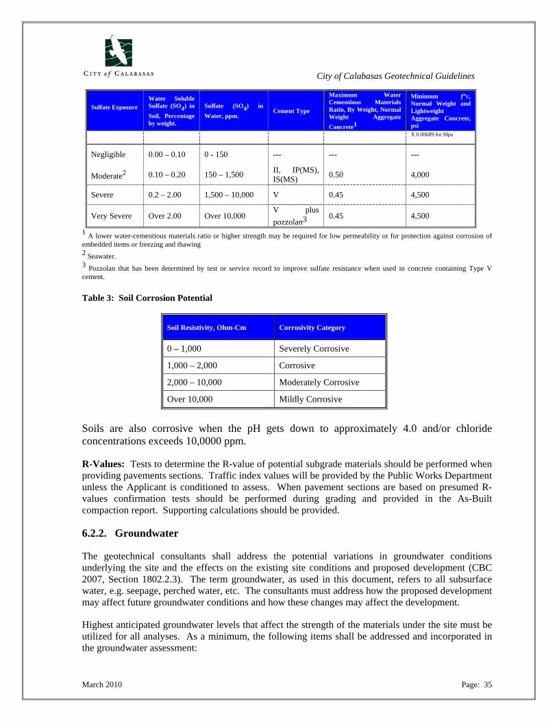
City of Calabasas Geotechnical Guidelines
March 2010 Page: 35
Sulfate Exposure
Water Soluble Sulfate (SO4) in Soil, Percentage by weight.
Sulfate (SO4) in Water, ppm.
Cement Type
Maximum Water Cementious Materials Ratio, By Weight, Normal Weight Aggregate Concrete1
Minimum f”c, Normal Weight and Lightweight Aggregate Concrete, psi
X 0.00689 for Mpa
Negligible 0.00 – 0.10 0 - 150 --- --- ---
Moderate2 0.10 – 0.20 150 – 1,500 II, IP(MS), IS(MS) 0.50 4,000
Severe 0.2 – 2.00 1,500 – 10,000 V 0.45 4,500
Very Severe Over 2.00 Over 10,000 V plus pozzolan3
0.45 4,500
1 A lower water-cementious materials ratio or higher strength may be required for low permeability or for protection against corrosion of embedded items or freezing and thawing 2 Seawater. 3 Pozzolan that has been determined by test or service record to improve sulfate resistance when used in concrete containing Type V cement. Table 3: Soil Corrosion Potential
Soil Resistivity, Ohm-Cm Corrosivity Category
0 – 1,000 Severely Corrosive
1,000 – 2,000 Corrosive
2,000 – 10,000 Moderately Corrosive
Over 10,000 Mildly Corrosive
Soils are also corrosive when the pH gets down to approximately 4.0 and/or chloride concentrations exceeds 10,0000 ppm.
R-Values: Tests to determine the R-value of potential subgrade materials should be performed when providing pavements sections. Traffic index values will be provided by the Public Works Department unless the Applicant is conditioned to assess. When pavement sections are based on presumed R-values confirmation tests should be performed during grading and provided in the As-Built compaction report. Supporting calculations should be provided.
6.2.2. Groundwater
The geotechnical consultants shall address the potential variations in groundwater conditions underlying the site and the effects on the existing site conditions and proposed development (CBC 2007, Section 1802.2.3). The term groundwater, as used in this document, refers to all subsurface water, e.g. seepage, perched water, etc. The consultants must address how the proposed development may affect future groundwater conditions and how these changes may affect the development.
Highest anticipated groundwater levels that affect the strength of the materials under the site must be utilized for all analyses. As a minimum, the following items shall be addressed and incorporated in the groundwater assessment:
City of Calabasas Geotechnical Guidelines
March 2010 Page: 36
1. Groundwater data such as reference to the current water level or piezometric head, seasonal changes along with historic high and historic low water tables, if available. For new construction projects, subsurface exploration is necessary to determine current groundwater levels underlying the site;
2. The effects of effluent from the proposed private sewage treatment system on groundwater
levels;
3. The effects of irrigation on groundwater levels;
4. The effects of potential heavy rainfall (such as the 1969, 1978, 1980, 1983, 1986, 1993, 1995, and 1998, 2005 rainfall years in California). It may in some cases be necessary for the consultant to distinguish the affects of high intensity versus long duration rainfall (i.e. the affects of rainfall from 1983 and 1986 versus 2005);
5. The potential for geotechnical hazards associated with groundwater (such as seepage, shallow
groundwater, springs, artesian conditions, hydro-static pressures, etc.).
6.2.3. Slope Stability Analyses
6.2.3.1 General
Slope stability analysis will be required for, but not limited to, the following conditions:
1. All critical cross-sections where development includes or is adjacent to slopes with a gradient steeper than 3:1 (horizontal:vertical);
2. Any slope which include a geologic/geotechnical hazard such as a landslide, daylighted
bedding, will require stability analyses;
3. All existing landslides or other forms of slope stability;
4. All temporary excavations in excess of 5 feet;
5. Trench excavations greater than 5 feet.
It is important to note that these conditions are guidelines, and site conditions may dictate that additional analyses may be required for lesser conditions than stated.
The critical cross-section is defined as the slope with the most adverse conditions, such as the steepest gradient, highest slope, most adverse geologic conditions, groundwater conditions, weakest soils and bedrock, etc. More than one cross-section may be considered the critical cross-section for geologically complex site. The critical failure surface should be identified and evaluated on each cross-section.
Numerous publications exist on the subject of slope stability and the various kinds of analysis and methodology. The Consultants should provide a thorough discussion of all assumptions, modeling, methodology, type of analysis, reasoning for shear strengths and the types of analyses performed, etc.
City of Calabasas Geotechnical Guidelines
March 2010 Page: 37
The more complex the site, the greater the discussion should be of the slope stability model of the site conditions.
Although not considered absolute, Standard of Practice for the Calabasas area would also encompass the guidelines published in: “Recommended Procedures for Implementation of DMG Special Publication 117, Guidelines for Analyzing and Mitigating Landslide Hazards in California organized through the American Society of Civil Engineers, Los Angeles Section (ASCE)”.
Subsurface geologic and groundwater conditions must be sufficiently evaluated and illustrated on geologic cross-sections and must be utilized by the geotechnical engineer for the slope stability analyses. If on-site sewage or storm water disposal exists or is proposed, the slope stability analyses shall include the effects of the effluent plume on slope stability.
All reports should address all hazards related to slope instability for all improvements, including but not limited to:
• Gross slope failures under Static and Pseudostatic Conditions;
• Surficial instability;
• Debris/Mudflow;
• Rockfalls;
• Slumps;
• Soil Creep
• Temporary Excavations
• Internal and external potential failure for designed buttress and MSE type walls.
6.2.3.2. Surficial Instability and Soil Creep
The potential effects of soil creep shall be addressed where any proposed structure is planned closer to the top of slope than the total slope height. The potential effects on the proposed development shall be evaluated and mitigation measures proposed, as appropriate, including appropriate setback recommendations.
6.2.3.3. Surficial Stability
Surficial slope stability refers to slumping and sliding of near-surface material and is generally most critical during the rainy season or with excessive landscape watering. The assessment of surficial slope stability shall be based on analysis procedures for stability of an infinite slope with seepage parallel to the slope surface or an alternate failure mode that would produce the minimum factor of safety.
The minimum acceptable depth of saturation for surficial stability evaluation shall be four (4) feet unless demonstrated that the thickness of surficial materials is less. All conclusions shall also be substantiated by appropriate analyses and data. Shear strengths shall be based on “saturated” samples tested at overburden pressures representative of the upper five feet of material. The material density should consider the long term weathering (i.e. a 90% compacted slope does not stay at 90% when
City of Calabasas Geotechnical Guidelines
March 2010 Page: 38
irrigated and planted). Alternatively, fills may be subject to reduced compaction as a result of dynamic loading, e.g. traffic loading. Therefore, the Consultant should address potential, foreseeable issues. The Consultant should ensure that the range of normal loading in lab tests is consistent with the field conditions.
If the surficial stability assessment indicates a computed safety factor of less than 1.5 that could affect the proposed building site, mitigation measures shall be provided. Surficial stability analyses shall be performed under rapid draw-down conditions where appropriate (e.g., for debris and detention basins).
Soils with a saturated, mobilized cohesion of less than 250 psf should be considered prone to erosion and may require mitigation measures.
6.2.3.4. Gross or Deep-Seated Stability
Gross stability includes rotational and translational deep-seated failures of slopes or portions of slopes that may directly or indirectly affect the site including removing adjacent lateral support.
The following guidelines shall be followed, but not limited to, when evaluating slope stability:
1. Stability shall be analyzed along cross-sections depicting the most adverse conditions (e.g. highest slope, adverse bedding planes, steepest slope). Often analyses are required for different conditions or more than one cross section to demonstrate which condition is most adverse. The critical failure surfaces on each cross-section shall be identified, evaluated, and plotted on the large-scale cross section;
2. For all new construction of habitable structures, including single-family residences, guest
houses, studios, multi-family residential projects, and commercial projects, and swimming pools, the minimum required long-term factor of safety is 1.5, minimum pseudo-static factor of safety is 1.1 or acceptable levels of deformation (Section 5.4.);
3. If the long-term, static factor of safety is less than 1.5, mitigation measures will be required to
bring the factor of safety up to the required level or the project may be re-designed so as to achieve a minimum factor of safety of 1.5. The minimum required factor of safety for temporary (during construction) excavations is 1.25;
4. Long-term stability shall be analyzed using the highest known or anticipated groundwater
level based upon a groundwater assessment performed as discussed in this manual;
5. Strengths utilized for landslide repairs design shall be no higher than the lowest computed using back calculation without justification or other mitigation measures. Assumptions regarding pre-sliding topography and groundwater conditions at failure must be discussed and justified. If the calculated factor of safety for a landslide mass is above the value that existed at the time of failure, it shall be shown what changes have taken place to result in the safety factor increase;
6. The report shall describe how the shear strength testing methods used are appropriate in
modeling field conditions and long-term performance of the subject slope. The utilized

City of Calabasas Geotechnical Guidelines
March 2010 Page: 39
design shear strength values shall be justified with laboratory test data, geologic descriptions and history, along with past performance history, if known, of similar materials;
7. Shear strength values higher than those obtained through site-specific laboratory testing will
not be accepted without supporting justification and prudent rationale;
8. Sufficient shear tests shall be performed on each material type to characterize and evaluate material variability;
9. Shear strengths for proposed fill slopes shall be evaluated using samples mixed and remolded
to represent anticipated field conditions. Confirming strength testing may be required during grading;
10. Design shear strengths for fill slopes shall be consistent with anticipated long-term
movements and obtained from samples that have reached a saturated condition;
11. Coordinates of the potential slide planes within the lowest safety factors for each mode of failure (rotation, block, etc.) should be depicted on cross-sections utilized in the analyses;
12. The stability analyses model shall consider and incorporate all adverse geologic conditions
such as joints, fractures, shears, faults, bedding planes, clay seams, gouge zones, clay beds, and landslide rupture surfaces;
13. Tension cracks and anticipated external loading shall be modeled, as appropriate;
14. All input files and output files shall be printed and be clearly legible;
15. If the program is one other than a commercially available program or the results cannot be
replicated, it may be necessary to provide the equations or other data to substantiate the findings. The appropriate reference should be included;
16. The following information shall be included on all geotechnical cross sections to illustrate the
results of the test:
• Surface coordinates (x,y). This should include a horizontal and vertical axis or reference point(s);
• Shear Strengths utilized;
• Groundwater level (s) and subsurface layers and input data;
• Critical failure surfaces with corresponding factors of safety should be depicted on the cross-sections utilized in the analyses;
• The 1.5 and 1.1 critical surface locations for the slope.
6.2.3.5. Seismically-Induced Slope Instability
Seismically induced slope stability (pseudostatic) analyses are required in all cases where static or gross slope stability is performed. A horizontal seismic coefficient of 0.2 can be assumed for all
City of Calabasas Geotechnical Guidelines
March 2010 Page: 40
analysis as a standard. Higher horizontal coefficients may be required where special conditions exist e.g. where geomorphic features exist that may exacerbate shaking.
Where factors of safety are less than 1.1 under pseusostatic conditions, a Newmark’s analysis may be used with the appropriate technical rationale to determine permanent slope deformations. The Consultant shall provide the necessary mitigation measures or demonstrate the area will be within acceptable limits for the proposed development.
6.2.6. Construction Stability
The report shall evaluate the construction stability (temporary stability) during grading, foundation construction and retaining wall excavations. See Sections 6.2.4 and 7.4 for discussion of minimum factors of safety, shoring and temporary excavations.
6.2.7. Liquefaction
Geotechnical consultants shall address the potential for liquefaction to occur at the site (including lateral spread and seismically-induced settlement) and identify whether the site is located within a Liquefaction Hazard Zone based upon the Seismic Hazards Maps published by the CDMG, experience in the City of Calabasas, or review of geotechnical studies on adjacent sites.
Proposed new development that qualifies as a project, as designated by the Seismic Hazards Mapping Act (1990) (and as defined in the California Public Resources Code sections 2621.6 and 2693), and is located within state-designated liquefaction hazard zones must perform a comprehensive liquefaction evaluation (including a quantitative) in conformance with CDMG Special Publication 117 and the SCEC “Guidelines for Analyzing and Mitigating Liquefaction in California” (Southern California Earthquake Center, March 1999). Special attention is drawn to “Recent Advances in Soil Liquefaction Engineering: A unified and Consistent Framework”, presented by R.B. Seed, et al., 2003 at the 26th Annual ASCE Los Angeles Geotechnical Spring Seminar. This paper has been the most current assessment of the state of liquefaction analysis and supplements and modifies the before mentioned publications.
Deviations from these guidelines should be described and justified. If an adequate factor of safety against liquefaction cannot be demonstrated (factor of safety against liquefaction must exceed 1.25), and it is determined that the effects of liquefaction exceed tolerable levels, mitigation measures to minimize the effects (i.e., preventing structural collapse, injury, loss of life) shall be provided.
In the case of one- and two-story single-family residences, a comprehensive liquefaction evaluation in conformance with CDMG Special Publication 117 is required when the site is located within a Liquefaction Hazard Zone. If, however, the site is not within a Liquefaction Hazard Zone and liquefaction is not considered a hazard at the site, then a rationale for that conclusion shall be provided. A rationale may consist of a site not being within a Liquefaction Hazard Zone and the Consultant being of and stating the opinion that the depth to groundwater, density of the soils, and other factors (all appropriately referenced), are sufficient to preclude the risk of liquefaction.
Comprehensive liquefaction studies are not required for swimming pools and spas, remedial repair projects, or additions and remodel projects, but the potential for liquefaction must be discussed. If the site is within a Liquefaction Hazard Zone, the report shall clearly inform the property owner of the risk, the potential consequences to the proposed improvements, and methods available to quantify the
City of Calabasas Geotechnical Guidelines
March 2010 Page: 41
risk. While the Seismic Hazards Mapping Act defines “residential project” subject to the act as developments of 4 or more dwellings, the Act does not prohibit the City from establishing guidelines which are more stringent than those established by Chapter 7.5 (Section 2624). The City will require liquefaction studies for all new habitable structures.
6.2.8. Seismically Induced Settlement
Granular soils, in particular, are susceptible to settlement during seismic shaking, whether the soils liquefy or not. The potential for seismically induced settlement to a depth of 50 feet shall be quantified for all projects except small additions and remodels, swimming pools and spas, and repairs.
When selecting the depths of borings to quantify seismically induced settlement to a depth of 50 feet, consideration can be given to geologic conditions at the site. It is only necessary to extend the borings to a depth where the deeper soils are expected to be sufficiently dense, based on geology, exploratory data in the area, and experience.
The estimated seismically induced settlement should extend from the depth explored plus the amount anticipated for materials between the depth explored to 50 feet. The presentation of results within the geotechnical report shall clearly present the rationale and supporting data when site specific data is not determined to a depth of 50 feet.
6.2.9. Settlement/Heave
Foundation and slab movements may result from settlement caused by seismic shaking and/or compression of supporting materials caused by live and dead loads of the foundations, settlement of compacted fill and underlying materials due to the weight of compacted fill, and swell or hydroconsolidation of supporting materials if moisture infiltrates these materials.
The geotechnical consultants shall analyze and estimate future total and differential movements of all footings, slabs, pipelines, and engineered fills supporting structures. The subsurface profiles used for settlement analysis shall be shown in cross-section and be substantiated by subsurface data. Settlement analysis calculations shall be submitted. If professional judgment is used in addition to or to modify the calculated settlement, justification or rationale upon which the judgment is made shall be provided. The magnitude of total and differential settlement shall be provided along with the computations. The estimated time for settlement to be 90% complete along with computations shall be provided where significant settlement is anticipated. Vertical movement estimations shall, as a minimum, consider:
1. Seismically induced settlement (See Section 6.2.8);
2. Compression of the fill materials due to their own weight;
3. Compression/consolidation of subsurface materials underlying fill;
4. Secondary consolidation, if it exists, of both fill and underlying subsurface materials;
5. Hydroconsolidation of fill and underlying subsurface materials (See Sections 4.5.2 and 6.2.1);
City of Calabasas Geotechnical Guidelines
March 2010 Page: 42
6. Settlement of foundations due to dead and live loads;
7. Potential heave due to swelling (expansive) soils (LL >50 or EI = High or greater).
A settlement-monitoring program shall be implemented during and after construction in situations where the anticipated settlement of fill and underlying materials, due to the added weight of fill, exceeds one inch (e.g. thick fills or fills overlying soft materials). Settlement monitoring shall consist of surface monuments and subsurface settlement plates.
7.0. GEOTECHNICAL ENGINEERING RECOMMENDATIONS
The following comments are intended to serve as a guide to the Geotechnical Consultant as to items the Reviewers will look for when reviewing geotechnical recommendations. The list, however, is not intended to be exhaustive. A number of additional issues have been identified in this Manual and specifically in Sections 5.0. through 6.0.
The Consultant must address each of the issues with supporting information. The Reviewers will not assume that unmentioned items are unimportant or do not need mitigation, even if in the opinion of the Reviewer such is the case. The geotechnical consultant has the responsibility to identify and discuss each issue, and provide mitigation measures if necessary. The following serves as a general guideline and the exact order and structure will be based on the style and intent of the Consultant.
7.1. Foundations
7.1.1. Shallow Foundations
Design of shallow foundations shall have a minimum design in accordance with CBC 2007, Section 1805 and shall include the following recommendations that are applicable:
1. Allowable bearing pressure. The minimum safety factor shall be stated when the allowable bearing pressure exceeds 2,500 psf;
2. Settlement analysis shall be performed when foundations exceed 36 inches in width, except
in bedrock;
3. Minimum slope setback (CBC 2007, Section 1805.3.1);
4. Estimated total and differential settlement;
5. Resistance to lateral loads (passive soil resistance and/or base friction) specified as ultimate or allowable with recommended safety factors. Safety factors must equal or exceed 1.5. A one-third increase in resistance for temporary (e.g., wind, seismic) loading will not be allowed for passive and base friction resistances, unless the safety factors for static conditions exceed two. If the recommended passive or sliding soil resistance relies on a cohesive strength component, the shear strength parameters shall be based on drained tests at overburden pressures representative of the application (less than 250 psf for shallow footings) and on samples that have been soaked and have a degree of saturation of about 100%. Cohesions measured on partially saturated (< 100%) samples will not be allowed to compute lateral resistances for shallow footings;
City of Calabasas Geotechnical Guidelines
March 2010 Page: 43
6. Requirements for compacted fill pads or over-excavation and recompaction;
7. Foundation surcharges;
8. Saturation requirements.
9. Inspection and approval requirements;
10. Any special considerations during design and construction.
7.1.2. Deep Foundations
Design of deep foundations shall be designed in accordance with CBC 2007, Section 1808 through 1812, and shall include each of the following that are applicable:
1. Allowable vertical loads (compression and uplift) as a function of foundation size, specify skin friction or end bearing, and safety factors used;
2. Pile or caisson-tip elevations or minimum depths of embedment;
3. Feasible pile and/or caisson types;
4. Potential for negative skin friction and effects on allowable vertical loads;
5. Lateral resistance from earth pressures;
6. Forces acting on the piles resulting from external loads, including soil creep, the effects of
liquefaction, seismic settlement or lateral spreading, and surcharge from adjacent structures or to achieve the appropriate factor of safety against slope failure;
7. Deflections of laterally loaded piles under design loads, where necessary;
8. Where necessary, LPile analysis or other similar program to demonstrate that no strain
incompatibility exists, and that the values assumed can be generated, i.e. that suitable movement can occur to mobilize the recommended skin friction or passive value without adversely affecting the structure or surrounding structures;
9. Special design or construction specifications, admixtures and other considerations.
7.2. Slab-On-Grade Construction
All slab-on-grade construction shall, as a minimum, conform to CBC, applicable edition. Recommendations should include subgrade reaction values and subgrade type and preparation. In addition, the allowable settlement/deflections for a given distance should be provided. In the event that the structural design cannot accommodate the deflections, recommendations for post-tensioned slabs or structural slabs should be provided.
City of Calabasas Geotechnical Guidelines
March 2010 Page: 44
Where applicable post-tension slabs should be utilized and designed in accordance with the Post Tension Slab Association or the Building Code.
Recommendations should also include soil saturation and specified depths. The report should also provide the necessary inspections that will be required.
7.2.1. Vapor Barrier Requirements
Recommendations for vapor barriers shall conform to CBC 2007 Section 1807 and be a minimum thickness of 10 mils Polyethylene. The Geotechnical Consultants shall provide specific recommendations for the thickness capillary break materials under the Vapor Barrier to reduce moisture infiltration.
The American Concrete Institute has published findings about excessive sand thickness as a primary cause of moisture infiltration. Recommendations should be provided as to sand gradation and thickness under slabs.
7.2.2. Expansive Soils
Specific foundation recommendations to mitigate the effect of expansive soils will be required for all foundations, slab-on-grade, and pools placed on soils with a Plastic Index greater than 15 (CBC 2007, Section 1802.3.2). This shall include but not limited to deepened edges, capillary break, and other alternatives such as post tensioned slabs, etc.
7.3. Retaining Structures
7.3.1. Standard Retaining Walls
Standard retaining walls are those gravity walls consisting of reinforced concrete or masonry block. Depending on the proposed development and site conditions, the report shall contain recommended earth pressures for proposed retaining structures. The design pressures should consider and/or incorporate:
1. Foundation types and design criteria if different from the building;
2. Lateral earth pressures for active and at rest conditions. This should include specifications for the application of at-rest pressures. All basement walls and other walls not free to rotate shall be designed as restrained using at-rest pressures. Calculations and explanations should be provided as to the methodology associated with the determination of the design values. Without justification, only Rankin’s analysis will be accepted;
3. Backfill specifications;
4. Wall subdrains. Without justification, drains should to within 24 inches of the top of the
backfill. In general, subdrains should consist of gravel and wrapped in filter fabric or an engineered designed gradational filter based on the U.S. Army Corp, without any further justification;
5. Existing and proposed surcharges;

City of Calabasas Geotechnical Guidelines
March 2010 Page: 45
6. Slopes, adversely oriented geologic features (bedding, joints, fractures, etc.) and any other
factors that may affect the lateral loads;
7. Acceptable wall rotations;
8. Consideration for temporary excessive equipment loading, if any;
9. Effects and pressures from expansive soils (CBC 2007, Section 1802.2.2 and 1802.3.2).
10. Waterproofing considerations;
11. Requirements for debris retention or interception by walls. All impact walls shall be design for 125 psf/ft unless otherwise justified. Volume calculations should be provided for debris
12. Free board requirements;
13. Surface drainage requirements;
14. Retaining walls higher than 12 feet shall be designed to resist additional earth pressures caused by seismic loading.
7.3.2. Non-Standard Retaining Structures
Non-Standard Structures are defined as retaining walls not composed of reinforced concrete or masonry block. Examples of non-standard retaining walls include crib walls, segmented-block walls, mechanically stabilized earth (MSE), and reinforced earth walls. In addition to the aforementioned requirements, the following items must also be considered for non-standard retaining structures:
7.3.2.1. Segmented Walls Adequate stability analyses must be performed to show that the integrity of the wall is maintained. All pertinent manufacturers’ specifications and recommendations for materials and installation shall be included in the report. All walls shall contain appropriate backdrainage for the entire height of the wall. Walls shall be backfilled with free-draining clean sand or gravel, including backfill within the cells, unless it is demonstrated that alternatives will perform acceptably. No structures shall derive any support from non-standard retaining walls unless it can be demonstrated that the vertical and lateral movements will be tolerable, under seismic loading. The engineer shall provide technical rationale for all design values. In general, design parameters assuming cohesion, and lateral pressures based on Coulombs will not be accepted unless justified. Design values and rationale supporting the design will not be based on manufacturer’s designs but rather on technical arguments, data, and established design procedures that are custom and practice in the industry. Where these walls will potentially impact a residence or structure, they will require that the design incorporate earthquake loading.
City of Calabasas Geotechnical Guidelines
March 2010 Page: 46
Any design will require:
a. Detailed grading plan with wall callouts every 25 feet and at the high points and ends of the wall.
b. Scaled cross sections and comprehensive calculations prepared by a registered civil engineer
experienced with the specific types of walls will be required;
c. Detailed slope stability analysis;
d. Construction specifications and tolerances;
e. In general, full time inspections by the geotechnical consultants will be required, and the City will provide site specific requirements during the review process.
7.3.2.2. Other Non-Standard Retaining Walls
A sufficient number of case histories may be required to substantiate the performance of the proposed walls under similar loading conditions.
7.3.2.3. Rockfall Catchment Walls and Structures
Rockfall catchment walls or structures or impact walls shall be provided based on engineering analysis. Alternatively, systems setforth by Caltrans and other agencies where case studies have been performed may be acceptable methods to mitigate site slope instability issues.
7.3.2.4. Surcharge Behind Retaining Walls
The geotechnical consultant should evaluate the potential for vertical and lateral surcharge on retaining walls due to adjacent structures, footings, traffic load, etc. A surcharge source located beyond a 1(H):1(V) projected plane could laterally surcharge retaining walls. Hence, using the 1(H):1(V) criterion to preclude the potential for lateral surcharge of retaining walls is not acceptable unless substantiated by appropriate analyses (e.g. methods of analysis presented in NAVFAC DM7.2).
7.4. Shoring and Temporary Excavations
Shoring systems are usually temporary supporting structures used to retain earth until the structure is completed. Shoring design parameters are used to determine the loads the retained soil will impose on the shoring units and must be provided by the geotechnical consultant. The geotechnical consultant shall evaluate the construction stability (temporary stability) during grading, foundation construction, and retaining wall excavations. All shoring shall be designed in accordance with the following criteria, and the stability evaluation section of the report shall, at a minimum, include the following:
1. A stability analysis model that considers and incorporates all applicable geologic discontinuities such as joints, shears, fractures, bedding planes and faults;
City of Calabasas Geotechnical Guidelines
March 2010 Page: 47
2. Shear strengths utilized should represent worst-case conditions anticipated at the time of excavation. Soil peak shear strength parameters in some cases may be utilized, however, to compute the shoring loads;
3. Tension cracks and anticipated external loading shall be modeled as appropriate;
4. Construction stability shall be analyzed on all potential critical cross-sections. The critical
failure surface on all cross-sections, should be identified and evaluated;
5. Construction stability should be analyzed utilizing worst-case groundwater levels anticipated at the time of excavation;
6. All temporary excavations shall possess a minimum factor of safety of 1.25. If the factor of
safety is less than 1.25, remediation/mitigation such as shoring to bring the safety factor up to 1.25 will be required;
7. Geotechnical consultants recommending shoring shall provide a geotechnical design
including, but not limited to, active and passive pressure magnitudes and lateral pressure distributions, type of shoring, the location and magnitude of any external loads that may affect the design and/or performance of the shoring systems, and minimum embedment for the restraint system;
8. If a slot cut type system is utilized, analysis will be required to demonstrate the stability of
excavated slots;
9. In cohesionless soils, full shield type shoring or other methods to prevent “running sands” should be provided;
10. All trench shoring must conform to the provisions of the California Labor Code/State Construction Safety.
These regulations can be obtained from CAL-OSHA. Applicable requirements of CAL-OSHA shall be discussed and incorporated into the excavation stability assessment. The geotechnical consultant shall address whether any construction dewatering will be necessary for the proposed excavations. The effects of the dewatering on adjacent existing structures/properties should be evaluated. The geotechnical consultant shall address the amount of anticipated deformation during construction and its effect on existing adjacent structures. The need for deformation monitoring during construction should also be addressed (if applicable). If an excavation affects the stability of existing structures and/or off-site property, shoring must be designed and installed to eliminate the hazardous condition. The design must be in accordance with all standards in this Guideline and must consider all factors such as slope stability, settlement, creep, etc. The soil strength parameters must be in accordance with the applicable criteria and shall not exceed the test values noted in the soils engineering report.
7.5. Grading Recommendations
The report shall contain sufficient and appropriate grading recommendations for the proposed grading in accordance with the City’s Grading Codes. Recommendations should include, but not limited to:
City of Calabasas Geotechnical Guidelines
March 2010 Page: 48
a. Site Preparation;
b. General Grading and Earthwork. This should include site specific grading recommendations;
c. Compaction. This should also include the standards and any specific requirements;
d. Bottom Excavations, Keyways, Shear Keys, Buttresses, etc., (CBC 2007, Figure J107.3);
e. Over-Excavation Requirements, Depths and Limitations. This should include measures to mitigate previous grading, test pits, and fault trenching, etc.;
f. Benching and Temporary Excavations (CBC 2007, Figure J107.3);
g. Subdrains;
h. Fill Slopes (CBC 2007, Section J107);
i. Cut Slopes (CBC 2007, Section J106);
j. Cut-Fill Transitions;
k. Temporary Excavations and Shoring;
l. Subgrade Stabilization;
m. Materials Excavations, Rippability and Special Considerations;
n. Earthwork Factors;
o. Erosion Control Measures (CBC 2007, Section J110);
p. Material Specifications.
7.5.1. Removal and Recompaction
Grading recommendations shall include comments on clearing and grubbing, removal of old fill, debris, and abandoned tanks and septic systems. Also, recommendations for the minimum depth and extent of the materials underlying the proposed foundations that need to be removed and recompacted shall be discussed. The report shall specify the minimum distance beyond the outside edge of shallow foundations for removal and recompaction, as determined by the engineer (i.e. 3 feet below bottom of foundations and 5 feet laterally, etc.). These recommendations shall be illustrated or noted on the Grading or Site Plans.
The report shall provide recommendations for a foundation system that will mitigate or reduce the effects of excessive settlement or heave (e.g. to a level in which service related problems such as non-functioning doors and windows or excessively sloping slabs would not occur). Minimum removal depths referenced to the bottom elevation of the proposed foundations shall be specified and be consistent with the settlement estimates.
City of Calabasas Geotechnical Guidelines
March 2010 Page: 49
7.5.2. Subdrains
Location and design specifications for subdrains, back drains and other subdrain systems shall be included in the geotechnical report. This shall include, but not be limited to, outlet location, size, gravel pack, flow gradient, filter fabric, etc. Additionally, the need for cut-off walls, glued joints, vertical and horizontal drains and design specifications shall be included. All outlet locations shall be equipped with protective devices.
The spacing (horizontal and vertical) shall be specified as necessary. Subdrains should be installed beneath all pools, and under all other water amenities (spas, fountains, ponds) when located in critical areas sensitive to subsurface water.
All subdrain locations and outlets shall be illustrated or noted on the Grading Plan or Site Plan. All drains and outlets will be required to be demonstrated on the As Built plans at the end of grading.
7.5.3. Cut/Fill Transition Areas
Consideration shall be given to potential differential foundation movements in cut-fill transitions and recommendations shall be provided to mitigate the risk of differential movements. As a minimum, fill thickness beneath foundations in cut/fill lots shall be at least three (3) feet, unless an alternative recommendation is justified on a site-specific basis. Recommendations for structural mitigation in the form of extra structural reinforcement of slabs and footings shall be provided, as necessary.
The Consultant should provide maximum thickness of fill differential from one side of the structure to the other to minimize differential settlement. Where the thickness will vary by more than 15 feet, the Consultants shall provide settlement calculations to justify the increased thickness.
7.5.4. Engineered Fills
All engineered fills and backfills should meet the provisions of the current edition of the City Building Code and the Uniform Building Code/California Building Code, latest edition (CBC Section 1803.5).
The Geotechnical Consultant shall provide specific recommendations for compaction, processing, soil-water content, and rock size and percentages for all fill. In general, rocks larger than 1 inch will not be permitted within the upper 5 feet of a building pad. Any rocks larger than 12 inches should require special handling. The degree and percentage of these materials must be specified in the report.
In general, all compaction shall be performed in accordance with ASTM D1557, latest. Any fill placed greater than 20 feet in thickness shall require 93 percent compaction, and fills greater than 50 feet shall require 95 percent compaction and horizontal blanket drains to alleviate elastic settlement unless otherwise specified by the Consultant. Fills in excess of 50 feet require settlement analysis.
The outer 10 feet of all fill slopes shall be compacted to 93 percent, unless justified by the Consultants. Areas of lesser compaction may be designated for landscaping consideration.
Whenever the organic content percentage as performed in accordance with ASTM D2974, latest, Method C or D exceeds two (2) percent, the material shall be considered detrimental and will not be acceptable. Treated wood lagging is not considered organic content.
City of Calabasas Geotechnical Guidelines
March 2010 Page: 50
No asphalt, petroleum materials, and other chemicals and potential hazardous waste shall be located in the fills.
In general soil cement is acceptable, but considerations should be made for landscaping.
7.5.5. Existing Fills
Grading plans must show all existing fills on a site and classify these fills as certified or uncertified, as well as identify all buttress fills. For any grading involving cutting into an existing fill slope, the geotechnical consultant must characterize the fill slope and provide slope stability analyses for the proposed and as-built conditions.
7.5.6. Fill Slopes
The Consultant shall include recommendations for keyways, benching, and drainage details. Fill slopes shall not exceed a 2:1 (horizontal to vertical) without special mitigation measures such as geogrid reinforcement or other technologies.
7.6 Drainage
The Geotechnical Consultant shall provide detailed surface drainage recommendations for the proposed development. Proper drainage and irrigation are important to reduce the potential for damaging ground/foundation movements due to hydroconsolidation and soil expansion or shrinkage and for mitigating adverse effects due to erosion that may endanger the integrity of the graded site, foundations, or flatwork. Recommendations must comply with the current edition of the California Building Code which includes five (5) percent slope away from the residence for 10 feet unless one of the exceptions is designed and incorporated into the design (CBC Section 1803.3).
The geotechnical report shall discuss and include, as appropriate, recommendations for:
i. Minimum slope gradients and distance for drainage away from foundations;
ii. Installing roof drains, area drains, catch basins, and connecting lines;
iii. Drainage or other mitigation measures beneath raised floors;
iv. Managing and type of landscape watering and maintenance of drainage devices;
v. Waterproofing systems for walls and floors when dealing with basements or when landscaping mounds are constructed against buildings;
vi. Maintenance guidelines for property owners;
vii. Requirements for subdrains around structures, ponds, fountains, pool, etc.
The geotechnical report should also discuss data from the Federal Emergency Management Agency (FEMA) Flood Insurance Rate Map (FIRM) should be reviewed and included if a flood zone is shown on or adjacent to the proposed development in order to assure that all flood hazards which may
City of Calabasas Geotechnical Guidelines
March 2010 Page: 51
affect the geologic and/or geotechnical conditions including the affects of scour and slope stability have been considered.
8.0. CONSTRUCTION OBSERVATION AND TESTING
The Project Consultant shall specify the observations and testing that they will require as part of their services to verify the findings, conclusions and specifications from a geologic and/or geotechnical standpoint. The Consultant should be familiar with the City Rough Grade and Fine Grading requirements for each project. If any questions exist, they should contact the City before the start of construction. In general, conditions will be imposed as Conditions of Approval during the Planning Stages, as well as, during the review stage by the Geotechnical Consultants.
The Consultants testing, observations and advice should include, but not limited to the following:
a. Mass and rough grading of the site. This will include keyways, shear keys, buttresses, canyon cleanouts, and other grading activities as discussed in this Manual as well as the Standard of Practice or as determined by the City Consultants. All grading will require continuous inspection per CBC 2007, Chapter 17, pg. 95, Table 1704.7;
b. All shoring activities, which may include regular reports;
c. Foundations and associated elements;
d. Slab-on Grade;
e. Retaining walls foundations, subdrains and backfill;
f. Pool excavations and subdrains;
g. Utility trench backfill including laterals;
h. Pavements;
i. All work in the public Right of Way;
j. Continuous testing and observations for landslide repairs, non-conventional retaining walls,
and other special conditions as deemed necessary by the City;
k. Final grading and drainage review and approval.
8.1. Pre-grade
The City will generally require as part of the approval process a Pre-Grading meeting at least 72 hours before the start of any construction. Present at this meeting includes the Project Civil Engineer, Grading Contractor, General Contractor and Geotechnical Consultant(s) to address the approved plans, construction schedule and sequencing.
Where a meeting is not required by the City, it will be the Owner/Applicants sole responsibility to be familiar with the City requirements and ensure the proper coordination.
City of Calabasas Geotechnical Guidelines
March 2010 Page: 52
8.2. Rough Grade
8.2.1. Construction Observations and Testing
During rough grade construction:
a. All grading observations in which the Geotechnical Consultant will “verify use of proper materials, densities, and lift thicknesses during placement and compaction of a controlled fill,” require continuous inspection. (CBC 2007, Chapter 17, pg. 95, Table 1704.7);
b. All pier foundation inspections require continuous inspection for all tasks in which the consultant will “observe drilling operations and maintain complete and accurate records for each pier,” in addition to “verify placement locations and plumbness, confirm pier diameters, bell diameters (if applicable), lengths, embedment into bedrock (if applicable), and adequate end bearing strata capacity.” (CBC 2007, Chapter 17, pg. 95, Table 1704.9);
c. The Geologic Consultant must observe all excavations into bedrock materials;
d. One duplicate sand cone test shall be performed for every ten nuclear gauge tests; e. Grain-size analyses shall be provided for all compaction curve samples; f. The Project Engineer shall observe and verify the foundation excavations during
construction.
8.2.2. Rough Grade Report
Rough grade reports will be prepared for all grading and drainage projects, or where retaining walls, pavement or other site elements may warrant geotechnical observations and testing.
The report should include all elements and the intent of Section 3.2.6 and Section 3.2.7. Following the completion of rough grading for a site, a rough grading report must be submitted but prior to any foundations or retaining walls unless specifically approved by Public Works and noted on the Grading or Site Plans. This report must contain the following information, as a minimum:
a. A map showing the as graded conditions and improvements following rough grading;
b. Fill compaction test data as well as any pertinent laboratory data;
c. Locations of the compaction test data plotted on the as graded map;
d. A statement addressing the projected total and differential settlement along with any calculations or pertinent data;
e. Verification by the soils engineer that the fill material shear parameters met or exceeded design values utilized in the soils report;
f. All soils engineering recommendations/mitigation measures;
City of Calabasas Geotechnical Guidelines
March 2010 Page: 53
g. Foundation and retaining wall recommendations; h. Section 111 statement addressing all completed work; i. All items specified in Section 3.2.6 and Section 3.2.7.
8.3. Final Grading Report
A Final Grading Report should be prepared upon the completion of grading for a site by the project Geotechnical Consultant. The report should include a discussion of any and all grading that was conducted following rough grade approval, this includes and is not limited to foundation excavations/footings, slab and subgrade construction (i.e. capillary break, sand, and vapor barrier), drainage, utility trenches, and any other grading that was not covered in the rough grade compaction report. Any pertinent maps and test data should be included as well. As discussed in Section 3.2.8., this report will provide but not limited to:
a. Any additional grading and compaction testing performed subsequent to the Rough Grade Report;
b. All utility trench back fill compaction testing and lab results;
c. All structural pavement soil subgrade and aggregate base rock compaction testing;
d. All slab subgrade compaction testing, capillary break, vapor barrier placement and sand placement;
e. All foundation observations and approvals. Where deep foundations are installed, downhole logs shall be provided where conditioned by the City. An As Built map shall be provided to demonstrate pile locations and depth shall be provided;
f. Expansion Index tests;
g. Any other structures or other improvements;
h. Any exclusions or testing that was not completed or found in conformance with the recommendations of the project consultants.