CITY OF NEWTON, KANSAS DESIGN STANDARDS FOR …
14
CITY OF NEWTON, KANSAS DESIGN STANDARDS FOR WATERLINE IMPROVEMENTS APRIL 2005
Transcript of CITY OF NEWTON, KANSAS DESIGN STANDARDS FOR …
CITY OF NEWTON, KANSAS
DESIGN STANDARDS
FOR WATERLINE IMPROVEMENTS
APRIL 2005

THE CITY OF
NEWTON, KANSAS
STANDARD ENGINEERING DESIGN CRITERIA AND
GENERAL IMPROVEMENT POLICY
TABLE OF CONTENTS
SECTION I - GENERAL A. Purpose 1-1 B. Scope 1-1 C. Variation from Design Criteria 1-1 D. Compliance with Applicable Statutory Requirements 1-2 E. Amendment to Standard Engineering Design Criteria 1-2 F. General Development Plan or Plat 1-2
SECTION V - WATER SYSTEM CRITERIA A. General V-1 B. Water Lines Materials and Design V-1 C. Trench and Backfill Requirements V-4 D. Fire Hydrants, Valves and Appurtenances V-5 E. Protection of Water Supplies V-6 F. Thrust Blocks V-6 G. Partial List of Bid Items V-7 H. Erosion Control V-7
THE CITY OF NEWTON, KANSAS
STANDARD ENGINEERING DESIGN CRITERIA AND
GENERAL IMPROVEMENT POLICY
LIST OF FIGURES
V-1 Waterline Details V-2 Bedding and Backfill Details V-3 Erosion Control & Sediment Barrier Details
No.
CITY OF NEWTON, KANSAS
STANDARD SPECIFICATIONS
FOR
WATERLINE IMPROVEMENTS
APRIL 2005
Revision Date
1-1
I. GENERAL
A. Purpose
The City of Newton is striving to provide uniformity in construction efforts
involving public works. To accomplish this it is important that initial design
comply with established standards and specifications approved by the City. In
addition to initial design, there are many construction activities that will be
performed which will not require design and construction documents, which must
also comply with uniform City standards. The following document will serve as
the standard guideline for all public works construction.
B. Scope
This document includes design criteria and typical construction details for Water
Systems. In addition a brief material specification will be outlined.
C. Variation from Design Criteria
Variations will be permitted from the Standard Engineering Design Criteria and
General Improvement Policy when a formal request is made to the City. The
request will involve the following:
1. List any and all variations being requested.
2. Provide a justification for each variation in writing. In the case of a detail,
provide a sketch or an engineered drawing indicating the modification
requested.
3. Request a formal meeting with the City to discuss the suggested variation.
4. Obtain in writing an approval of the modification.
Special circumstances may be encountered where a specific item is not included
in the Standard Engineering Design Criteria and General Improvement Policy. If
1-1
this occurs, a formal request shall be made to the City and shall meet the
requirements as shown above for a variation.
D. Compliance with Applicable StatutOry Requirements
Compliance with all Federal, State and Local Laws will be required . Where
permits are required by Federal, State and Local Agencies, the Project Owner
will be required to complete all filing, pay all fees, and obtain an approved permit.
All information including maps, plans, specifications, etc. , required to obtain an
approved permit shall be provided to the City. Traffic control for all projects shall
be established and shall conform to the latest version Manual on Uniform Traffic
Control (MUTCD).
E. Amendment to Standard Engineering Design Criteria
Amendments to the Standard Engineering Design Criteria and General
Improvement Policy will be approved by the City. The Amendments will be made
available by the City for insertion into this document. It is the responsibility of the
holder of this document to assure themselves that they have all the amendments
or a current document.
F. General Development Plan or Plat
Any development plan or proposed plat shall be submitted to the City with
utilities and pavement generally located within the boundary of the plan or plat.
For plats the utilities will be located within dedicated easements and right-of
ways. The general development plan or plat shall show preliminary elevations
for all sanitary sewers, streets, and storm drainage conveyance systems. In
addition, the project owner for a plat shall submit a four corner lot grading plan
indicating elevations at each corner for the subdivision that is being developed.
The four corner lot grading plans will be placed on file with the City and will be
reviewed during requests for building permits.
1-2

V. WATER SYSTEM CRITERIA
A. General
Design of water systems shall meet the Policies, General Considerations, and
Design Requirements for Public Water Systems in Kansas, as established by the
Kansas Department of Health and Environment (KDHE) and shall also meet the
requirements of the City of Newton Design Standards as herein outlined. Prior to
submittal to KDHE, the designer shall provide the City with two sets of Office
Copy plans for review and comment. The designer shall submit a Public Water
Supply Permit as required along with plans, specifications, and two extra plan
and specification covers to KDHE and must obtain approval prior to the bid
letting. The requirement of submitting a Public Water Supply Permit may be
waived by KDHE for projects with less than 5,280 feet of total length of water
line.
B. Water Line Materials and Design
Approved pipe material for use on water lines shall include Ductile Iron Pipe
(DIP).
1. Ductile Iron Pipe
DIP shall be minimum thickness class 52 and shall be cement lined and
seal coated with an approved bituminous seal coat in accordance with
AWWA C-1 04. Polyethylene encasement shall be provided for a DIP and
fittings.
V-1

2. PVC Pipe
The use of PVC pipe for waterline construction may be allowed only with
prior approval by the City of Newton. PVC pipe 4" and larger shall be
AWWA C-900, pressure class 150 pipe. Fittings for use with DIP or PVC
pipe shall be CICL or DICL conforming to AWWA C11 O. Compact fittings
may be used conforming to AWWA C153.
3. Design Considerations
The minimum depth of cover for all water lines shall be 42". Minor
deflections of PVC pipe shall be made through the use of couplings. The
maximum deflection shall not exceed 4° . High points in the profile of
water lines shall be minimized. High points shall be located where fire
hydrants or other outlets are located. Detectable metallic tape shall be
placed over all water lines constructed. The tape shall be blue with a
warning message of "CAUTION - BURIED WATERLINE BELOW" being
included on the tape. All PVC waterlines shall include tracer wire installed
for future locating of the waterlines.
4. Water Line Sizing
Water lines shall be sized based on peak demands from the service area.
Minimum diameter of public water lines will be 4". Water lines serving fire
hydrants or fire protection systems shall be a minimum of 8" in diameter.
5. Water Line Location
Water lines shall typically have an 8' offset off property lines, and shall be
located within public street right-of-way. If required, easements shall be
obtained for installation and maintenance purposes. Any water line
V-2

locations which are not in public street right of way shall be approved by
the City. Water lines shall typically be located on the north and east
portions of right of ways and easements.
6. Testing
All completed water lines shall be subjected to a pressure and leakage
test. The pressure test consists of the water line being subjected to the
rated working pressure of the pipe installed (typically 150 psi) for a period
of 1 hour. A two hour leakage test will follow the pressure test. An
approved leakage test will consist of an allowable leakage quantity not
being exceeding in the two hour time period. The allowable leakage is
calculated based on the following equation:
PVC Pipe L = 0.0001351 (N) (D) (P) 1/2
Ductile Iron Pipe L = 0.0000075 (S)(D)(p)1/2
L = Allowable Leakage (gal/hr)
o = Nominal Pipe Diameter (in)
P = Pressure (PSIG)
S = Length of Pipe Tested (ft)
N = Number of joints in tested section
7. Disinfection
All completed water lines shall be flushed and disinfected per AWWA
C601. Waterlines shall be disinfected by the "continuous feed" method.
A chlorine concentration of 50 mg/l shall be introduced into the newly
constructed water line. The chlorinated water shall remain in the water
line for a 24-hour period. At the end of the 24 hour period, the residual
chlorine concentration shall be 25 mg/l (minimum). The water lines shall
V-3
then be flushed so the final chlorine concentration in the water line is less
than 1 mgll.
C. Trench and Backfill Requirements
Approved material includes UD-1 meeting KDOT Standard Specifications or
ASTM C-33 Size No. 67 crushed rock (granular) material. Approved backfill
material includes approved granular material (sand) free from debris, organic
material and stones with 100% passing thru 3/4" sieve or compacted earth.
1. Trenching through Pavement
Pavement shall be saw cut in a neat line and replaced to a depth of 1 1/3
times the original pavement thickness. The replaced pavement shall be
widened a minimum of 12" each way from the trench limits.
2. Backfilling Under Pavement
Pavement backfill material shall be compacted sand or excavatable
flowable fill as approved by the City. The material shall be backfilled to a
level 2' from the bottom of pavement.
3. Pipe Zone Backfilling
Class B bedding shall be used for flexible pipe. Class C bedding shall be
used for rigid pipe. If wet conditions are encountered, Class B or C improved
bedding shall be utilized.
V-4

4. Protective Fill
Protective fill shall be provided during construction where the cover over the
proposed water line is less than 2 feet. Protective fill shall be placed and
compacted in place prior to construction of the water line. The completed
waterline shall have a minimum cover of 42".
D. Fire Hydrants, Valves and Appurtenances
Water line fire hydrants, valves, appurtenances shall meet all requirements as
established by AWWA, and as set forth in the City of Newton Design Standards as
herein outlined.
1. Fire Hydrants Assembly
Fire hydrants shall be Mueller Centurion A-423. The fire hydrant assembly
shall include an MJ Anchor Tee, 6" MJ Gate Valve, 6" Valve box, and a
variable length of 6" DICL. Fire hydrant spacing shall be a maximum of 400'.
Fire hydrants shall be located near intersections and within 3-8 ft from
existing or proposed curbs/edge of road.
2. Valves
Resilient Seat Gate Valves meeting AWWA C509 with a non-rising stem and
square operating nut shall be furnished for use on 12" water lines and
smaller. Gate valves shall be as manufactured by Mueller or AVK. Valves
greater than 12" shall be Butterfly valves meeting AWWA C504.
Anchored valve assemblies shall include the use of an MJ Anchor Coupling
for pipes 12" and smaller. For larger pipes, restrained joints shall be used as
thrust restraint for the anchored valve.
V-5
3. Valve Boxes
Valve boxes shall be cast iron with lock type cover extension with a screw
type adjustment. Valve boxes shall be 4" diameter with a flared base. Wall
thickness shall be 3/16" thick. Valve box tops shall be set flush with
proposed grade.
4. Blow-Off Assembly
Blow off assemblies shall be provided at the end of water lines only with prior
approval from the City. The designer shall minimize the use of blow off
assemblies by installation of fire hydrants in locations that will require air
release or flushing of the water lines in lieu of blow off assemblies.
E. Protection of Water Supplies
When potable water pipes and sanitary sewers are laid parallel to each other,
the horizontal distance between them shall be not less than 10 feet. The laying
of water pipes and sanitary sewers shall be in separate trenches with
undisturbed earth between them.
When a water pipe and a sanitary sewer cross and the sewer is 2 feet or more
(clear space) below the water pipe, no special requirements or limitations are
provided herein. At all other crossings, the sanitary sewer is to be constructed of
Ductile Iron, PVC, or Reinforced Concrete pipe, meeting the requirements
specified in Section 02605 - Sanitary Sewer Construction.
Joints in the sewer pipe shall be located as far as practical from the intersected
water main. A distance of 10 feet is to be maintained as the distance of a sewer
joint to the water line.
Where a water main is laid across or through an area where there is an existing
sanitary sewer, which is not constructed of one of the above specified materials,
and is two feet (2') or less below the water pipe, the existing sanitary sewer shall
V-6
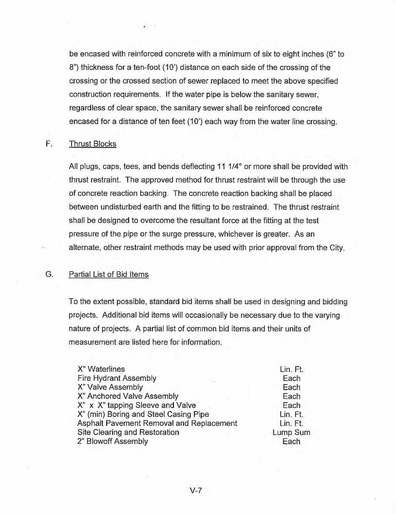
be encased with reinforced concrete with a minimum of six to eight inches (6" to
8") thickness for a ten-foot (10') distance on each side of the crossing of the
crossing or the crossed section of sewer replaced to meet the above specified
construction requirements. If the water pipe is below the sanitary sewer,
regardless of clear space, the sanitary sewer shall be reinforced concrete
encased for a distance of ten feet (10') each way from the water line crossing.
F. Thrust Blocks
All plugs, caps, tees, and bends deflecting 11 1/40 or more shall be provided with
thrust restraint. The approved method for thrust restraint will be through the use
of concrete reaction backing. The concrete reaction backing shall be placed
between undisturbed earth and the fitting to be restrained. The thrust restraint
shall be designed to overcome the resultant force at the fitting at the test
pressure of the pipe or the surge pressure, whichever is greater. As an
altemate, other restraint methods may be used with prior approval from the City.
G. Partial List of Bid Items
To the extent possible, standard bid items shall be used in designing and bidding
projects. Additional bid items will occasionally be necessary due to the varying
nature of projects. A partial list of common bid items and their units of
measurement are listed here for information.
X" Waterlines Fire Hydrant Assembly X" Valve Assembly X" Anchored Valve Assembly X" x X" tapping Sleeve and Valve X" (min) Boring and Steel Casing Pipe Asphalt Pavement Removal and Replacement Site Clearing and Restoration 2" Blowoff Assembly
V-7
Lin. Ft. Each Each Each Each
Lin. Ft. Lin. Ft.
Lump Sum Each
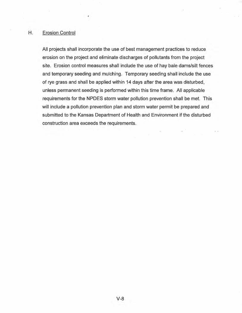
H. Erosion Control
All projects shall incorporate the use of best management practices to reduce
erosion on the project and eliminate discharges of pollutants from the project
site. Erosion control measures shall include the use of hay bale dams/silt fences
and temporary seeding and mulching. Temporary seeding shall include the use
of rye grass and shall be applied within 14 days after the area was disturbed,
unless permanent seeding is performed within this time frame. All applicable
requirements for the NPDES storm water pollution prevention shall be met. This
will include a pollution prevention plan and storm water permit be prepared and
submitted to the Kansas Department of Health and Environment if the disturbed
construction area exceeds the requirements.
V-8