CITY OF CHESAPEAKE PUBLIC FACILITIES MANUAL … · DIVISION 46 Treated Timber Pile DIVISION 47...
349
Rev. 2/93 i CITY OF CHESAPEAKE PUBLIC FACILITIES MANUAL VOLUME 3 TECHNICAL SPECIFICATIONS TABLE OF CONTENTS REVISED DATE I. DEFINITIONS 2/93 II. REQUIREMENTS FOR DEVELOPMENT 2/93 III. TECHNICAL SPECIFICATIONS ROADWAY CONSTRUCTION DIVISION 1 Regular Excavation DIVISION 2 Undercut Excavation DIVISION 3 Allaying Dust DIVISION 4 Select Borrow I, CBR 20 DIVISION 5 Select Borrow II, CBR 15 DIVISION 6 Aggregate Base and Subbase Course DIVISION 7 Asphalt Concrete Base Course DIVISION 8 Liquid Asphalt Coat DIVISION 9 Asphalt Concrete Surface Course 2/96 DRAINAGE CONSTRUCTION DIVISION 10 Storm Drain Pipe and Flared End Sections 4/95 DIVISION 11 Catch Basins, Manholes, Conflict Manholes and Drop Inlets DIVISION 12 Box Culvert Concrete, Headwalls, and Endwalls DIVISION 13 Reinforcing Steel (Box Culvert) DIVISION 14 Bedding Material (Box Culvert) DIVISION 15 Minor Structure Excavation (Box Culvert) DIVISION 16 Bedding Material (Drainage and Utility Pipe) DIVISION 17 Sand Cement Bag Rip-Rap and Ditch Regrading INCIDENTAL CONSTRUCTION DIVISION 18 Mobilization DIVISION 19 Clearing & Grubbing 8/94 DIVISION 20 Topsoil & Seeding and Restoration DIVISION 21 Pavement Patching DIVISION 22 Curb & Gutter and Other Incidental Concrete DIVISION 23 Erosion and Sediment Control
Transcript of CITY OF CHESAPEAKE PUBLIC FACILITIES MANUAL … · DIVISION 46 Treated Timber Pile DIVISION 47...

Rev. 2/93 i
CITY OF CHESAPEAKE PUBLIC FACILITIES MANUAL VOLUME 3
TECHNICAL SPECIFICATIONS
TABLE OF CONTENTS
REVISED DATE
I. DEFINITIONS 2/93
II. REQUIREMENTS FOR DEVELOPMENT 2/93
III. TECHNICAL SPECIFICATIONS
ROADWAY CONSTRUCTION
DIVISION 1 Regular Excavation DIVISION 2 Undercut Excavation DIVISION 3 Allaying Dust DIVISION 4 Select Borrow I, CBR 20 DIVISION 5 Select Borrow II, CBR 15 DIVISION 6 Aggregate Base and Subbase Course DIVISION 7 Asphalt Concrete Base Course DIVISION 8 Liquid Asphalt Coat DIVISION 9 Asphalt Concrete Surface Course 2/96
DRAINAGE CONSTRUCTION
DIVISION 10 Storm Drain Pipe and Flared End Sections 4/95 DIVISION 11 Catch Basins, Manholes, Conflict Manholes and Drop Inlets DIVISION 12 Box Culvert Concrete, Headwalls, and Endwalls DIVISION 13 Reinforcing Steel (Box Culvert) DIVISION 14 Bedding Material (Box Culvert) DIVISION 15 Minor Structure Excavation (Box Culvert) DIVISION 16 Bedding Material (Drainage and Utility Pipe) DIVISION 17 Sand Cement Bag Rip-Rap and Ditch Regrading
INCIDENTAL CONSTRUCTION
DIVISION 18 Mobilization DIVISION 19 Clearing & Grubbing 8/94 DIVISION 20 Topsoil & Seeding and Restoration DIVISION 21 Pavement Patching DIVISION 22 Curb & Gutter and Other Incidental Concrete DIVISION 23 Erosion and Sediment Control
Rev. 2/93 ii
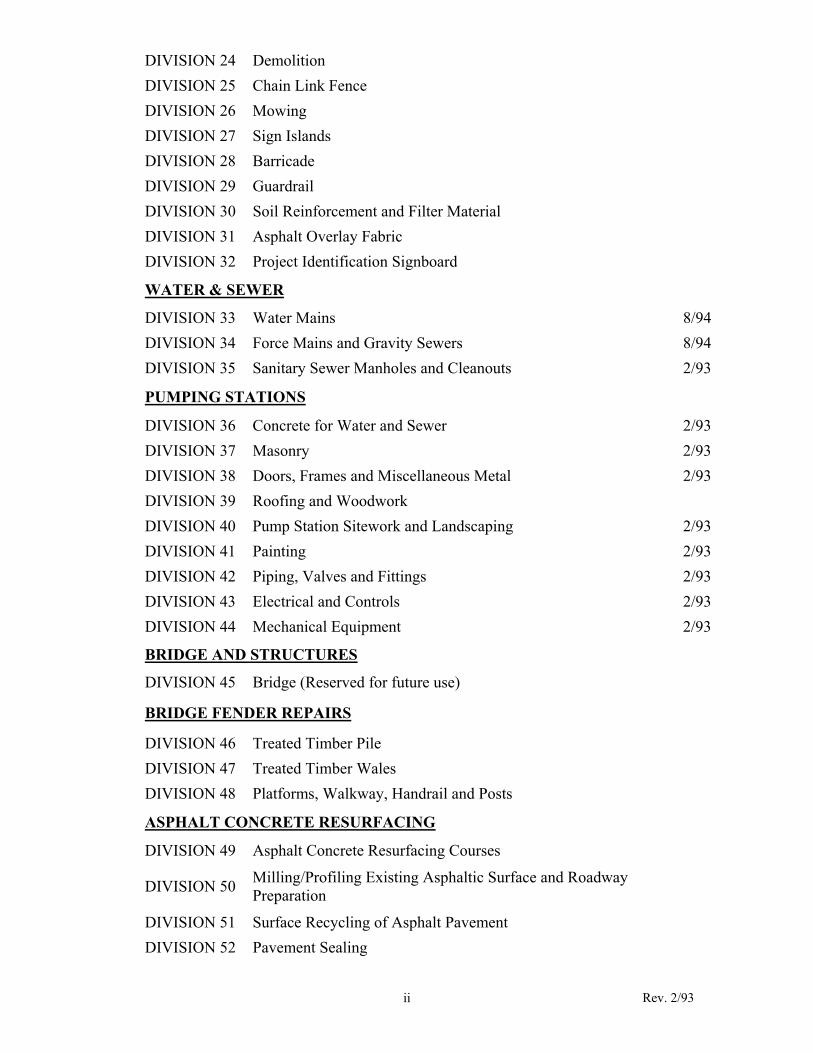
DIVISION 24 Demolition DIVISION 25 Chain Link Fence DIVISION 26 Mowing DIVISION 27 Sign Islands DIVISION 28 Barricade DIVISION 29 Guardrail DIVISION 30 Soil Reinforcement and Filter Material DIVISION 31 Asphalt Overlay Fabric DIVISION 32 Project Identification Signboard
WATER & SEWER
DIVISION 33 Water Mains 8/94 DIVISION 34 Force Mains and Gravity Sewers 8/94 DIVISION 35 Sanitary Sewer Manholes and Cleanouts 2/93
PUMPING STATIONS
DIVISION 36 Concrete for Water and Sewer 2/93 DIVISION 37 Masonry 2/93 DIVISION 38 Doors, Frames and Miscellaneous Metal 2/93 DIVISION 39 Roofing and Woodwork DIVISION 40 Pump Station Sitework and Landscaping 2/93 DIVISION 41 Painting 2/93 DIVISION 42 Piping, Valves and Fittings 2/93 DIVISION 43 Electrical and Controls 2/93 DIVISION 44 Mechanical Equipment 2/93
BRIDGE AND STRUCTURES
DIVISION 45 Bridge (Reserved for future use)
BRIDGE FENDER REPAIRS
DIVISION 46 Treated Timber Pile DIVISION 47 Treated Timber Wales DIVISION 48 Platforms, Walkway, Handrail and Posts
ASPHALT CONCRETE RESURFACING
DIVISION 49 Asphalt Concrete Resurfacing Courses
DIVISION 50 Milling/Profiling Existing Asphaltic Surface and Roadway Preparation
DIVISION 51 Surface Recycling of Asphalt Pavement DIVISION 52 Pavement Sealing

Rev. 2/93 iii
SLIP-LINING OF EXISTING SEWER LINE
DIVISION 53 Slip-Lining of Existing Sewer Line
INSITUFORM LINING
DIVISION 54 Insituform Lining
BY-PASS PUMPING
DIVISION 55 By-Pass Pumping
BORED PIPE
DIVISION 56 Bored Ppe 8/94
WORK ON RAILROAD PROPERTY
DIVISION 57 Work on Railroad Property
TRAFFIC CONTROL
DIVISION 58 Traffic Signal 3/03 DIVISION 59 NEMA TS2 Fully Actuated Traffic Controller (New Div.) 3/03 DIVISION 60 Wide Area Video Vehicle Detection System (New Div.) 3/03 DIVISION 61 Light Emitting Diode Vehicle Signal Modules (New Div.) 3/03 DIVISION 62 Traffic Signs 3/03 DIVISION 63 Street Name Signs (New Div.) 3/03 DIVISION 64 Internally Illuminated Street Name Sign (New Div.) 3/03 DIVISION 65 Maintenance of Traffic 3/03 DIVISION 66 Pavement Markers and Markings 3/03 DIVISION 67 Detour 3/03
DIVISION 68 Right-of-Way Restoration and Temporary Construction Requirements 3/03
DIVISION 69 Traffic Signal Interconnect Cable 3/03 DIVISION 70 Detectors 3/03
Foreword This publication is intended primarily for use by those persons involved in the construction of all types of public improvements as well as City Personnel in order to impose uniform requirements. This manual is the third volume of the Public Facilities Manual and proper use will require reference to Volume II, City Standards. While every attempt has been made to address all requirements, this manual may not necessarily cover all special or unusual circumstances. All development activity is subject to the requirements of Chesapeake City Code, applicable State and Federal Codes, as well as those dictated by sound engineering and construction practice. This manual represents a significant effort by City staff members and was developed with the input of the engineering consultants representing the development sector. While many of the sections were revived from contract documents from past City projects, old contract documents should not be used in place of this manual since several sections have received significant revisions. The City of Chesapeake accepts no liability for the use of this manual except that required in the execution of a City contract or for the construction of public improvements pursuant to an approved development plan.

Volume III I. Definitions City The word "City" refers to the City of Chesapeake, Virginia or its duly authorized
representative. City Project Improvements performed pursuant to a contract with the City. Contractor The word "Contractor" refers to the person, firm or corporation with whom the Owner
has entered into an agreement to perform construction activity. Development A tract of land developed or to be developed as a unit under single ownership or
unified control which is to be used for any business or industrial purpose or is to contain three (3) or more dwelling units. The term "Development" shall not be construed to include property which will be principally devoted to agricultural production. A Development shall include sites, subdivisions, S.D.M.P.'s and any private extension of public facilities.
Engineer The word "Engineer" refers to the City of Chesapeake's Engineer in all projects
whether publicly or privately funded unless otherwise specified herein. Engineer shall include any engineer or inspector whom the City designates in the role of Engineer.
Owner The word "Owner" refers to the City of Chesapeake when the construction plan is a
City project. The word "Owner" refers to the Developer when the construction plan is for a development, and the Developer shall be responsible for the Contractor's actions and performance. The Developer is the person, Firm or Corporation who has posted surety and is ultimately responsible for making the improvements shown on the Approved Construction Plan.
Work "Work" is the result of performing services, furnishing labor and furnishing and
incorporating materials and equipment into the construction all as required by the approved Construction Plans, Contract Documents and the Public Facilities Manual, Volumes II and III.
2/93
2

Revised 4/95
D - 1
II. REQUIREMENTS FOR DEVELOPMENT
1. WORK OUTSIDE REGULAR HOURS:
No work shall be done outside the regular hours or on Sundays or holidays without prior notification to the Engineer.
2. PERMITS, CONNECTION FEES, AND UTILITY SERVICES:
The Owner shall be responsible for obtaining and paying for all required permits. The Owner shall be responsible for paying all connection fees.
The Owner shall be required to pay for any City services provided to include water procured for cleaning,
flushing, testing, or other construction purposes during the course of the work.
3. PERFORMANCE AND DEFECT BOND:
The Owner may proceed with the installation of improvements based on the approved construction plans and apply for recordation of the subdivision after all improvements on the approved construction plan have been accepted by the City. In lieu of this, the Owner may elect to post a bond assuring the installation of all improvements and apply for recordation prior to actual construction taking place. In addition a defect bond to guarantee the performance of the requirements of this division for a period of one year unless otherwise provided from the date of acceptance shall be required.
4. ORDINANCES HAVING JURISDICTION OVER WORK:
The Owner is hereby directed to familiarize himself with, and be governed by, all ordinances of the City
of Chesapeake and such other agencies as may have jurisdiction over the work. Below are summaries of several such ordinances to which the Owner's particular attention is directed. It is emphasized that these are summaries only, and not all-inclusive and that the Owner should read the individual ordinances themselves to be certain of their contents.
a. Chapter 28A. Wetlands Zoning. Prior to the placing of any amount of fill material on any type of
wetlands, as legally defined, it is first necessary to obtain a Wetlands Permit from the City of Chesapeake Wetlands Board. Wetlands, as legally defined, includes all that land lying between and contiguous to mean low water and an elevation above mean low water equal to the factor 1.5 times the mean tide range at the site of the proposed project, and, upon which is growing any one or more of the 35 species or families of plant species listed in the City ordinance. Owners contemplating filling within this zone shall obtain clearance through the Chesapeake Department of Planning, Telephone Number 547-6176, prior to such filling.
b. Chapter 29. Zoning. Article VI of the Zoning Ordinance of the City of Chesapeake entitled
"Tabulation of Permitted and Conditional Uses", states that landfills one acre or more in size are permitted only after first obtaining a Use Permit from the City Council of the City of Chesapeake. Owners contemplating land fills greater than one acre in size shall file for a Use Permit with the Department of Planning, Telephone Number 547-6176, prior to undertaking such activity.
c. Chapter 21. Refuse, Garbage and Weeds. No garbage, trash or similar materials may be deposited
anywhere in the City except as may be approved by the City Manager or his authorized Delegate. The Director of Public Works, acting as said Delegate, may grant a permit for solid fill material

suitable for landfill purposes to be deposited on areas less than one acre in size. For additional information, contact the Permits Engineer of the Public Works Department, Telephone Number 547-6101. Larger fill operations would require a Use Permit obtained as mentioned in Item (b) above. The depositing of material accumulated from outside the City, and placing or dumping of rubbish or debris onto public property is also forbidden.
d. Chapter 28. Blockage of Drainage. It is unlawful for any person to block or interfere with the flow of
water in any ditch, watercourse or drainage easement unless approval is obtained from the Department of Public Works. Any questions on this ordinance should be directed to the City Engineer at the Public Works Department, Telephone Number 547-6101. Any violation is a misdemeanor, and each day's continued violation is a separate offense.
5. TRAFFIC CONTROL:
a. All signing, barricades, drums and other traffic controls shall be in accordance with the Federal
Manual on Uniform Traffic Control Devices, (1978) including all changes and revisions to date and the Virginia Work Area Protection Manual dated January 1987 with all changes and revisions. Whichever is more restrictive shall apply.
b. All construction signs shall have orange flags. Any signs used at night shall be reflectorized and have
flashing amber lights.
c. Protective devices shall be in accordance with the Virginia and Federal manuals described above. Lights used to protect work area, equipment or other hazardous areas at night shall have flashing amber lights. All lights used to delineate the lanes at night shall have steady burn amber lights.
d. The Owner shall notify the Traffic Engineering Division (547 -6101) 48 hours in advance of
beginning work or the closing of any street.
e. Plans for the signing, barricading and other traffic controls and/or detours shall be furnished by the Owner for approval by the Engineer. Such plans shall be submitted 7 working days in advance for the time needed through the Engineer.
f. Where primary highways or major roadways are paved, pavement markings shall be installed
promptly after the paving. If the construction work requires changes be made in the traffic pattern, the final asphalt pavement surface shall not be applied until such work is done, in order that temporary pavement markings may be applied to the base coat.
g. The Owner shall check all signs, drums and barricades connected with this project every morning before work and evening when work is stopped for the day to ensure that they are in proper order. On weekends, holidays and when the project is shutdown, the Owner shall have these traffic control devices checked daily to see that they are properly located and operating.
h. The Owner shall maintain access to all properties, especially for emergency vehicles, at all times.
I. Work shall be conducted in such a manner as to cause a minimum delay to school bus traffic. When traffic is being flagged, the flag person(s) shall expedite the movement of these busses, particularly in the morning.
j. At anytime the project is not properly signed, barricaded or otherwise found unsafe so as to create a
danger to the safety or the general public, the Engineer and/or City Safety Officer may have work stopped until such conditions are corrected.
Revised 4/95
D - 2
k. The signing, barricading, pavement marking and other traffic controls and/or detours may be changed at any time during the project when deemed necessary in the opinion of the Engineer, and to have such changes made shall be the responsibility of the Owner. All pavement markings, whether temporary or permanent, shall be fully retro reflective.
l. When flaggers or other means of traffic control are used for one lane traffic, strict adherence to
Manual on Uniform Traffic Control Devices Section 6. f. Control of Traffic Through Work Areas, shall be required.
6. SERVICE COMPLAINTS: Service complaints caused by the Owner, in the opinion of the Engineer, shall be repaired by the Owner
immediately. Failure to respond to the service complaint shall cause the City to investigate and correct the situation at the Owner's expense.
7. UTILITY COORDINATION AND MAINTENANCE OF SERVICE:
The Owner shall insure that any public or private utility companies or agencies having facilities in the right-of-way and facilities that would prevent the performance of the work, relocate, adjust or remove same so as to permit the work. It shall be the Owner's sole responsibility and expense to determine the precise nature and extent of conflicts (with assistance from the utility agency if required), and to coordinate with the utility(ies) to insure that the timing and location of adjustments are such as to minimize their inconvenience and expense, to cause no delay of the work, and to cause minimal inconvenience to residents in the area of the work. Further, the Owner shall be responsible to maintain all existing water mains and sewer lines during construction operations and repair any service problems immediately. Failure to correct any problem shall cause the City to do so at the Owner's expense.
8. CONSTRUCTION RECORD DRAWINGS:
The Owner is required to submit to the City "as built" plans with two (2) sets of (double matte, 3 mil minimum) mylar and three (3) sets of prints to the City prior to the City's final acceptance and in accordance with the requirements of Chapter One, Section II and Appendix III of Volume I of the City's Public Facilities Manual.
9. WEATHER CONDITIONS:
In the event of temporary suspension of work, or during inclement weather or whenever the Engineer shall direct, the Owner will protect carefully his work and materials and existing public facilities against damage or injury from the weather. If, in the opinion of the Engineer, any work or materials shall have been damaged or injured by reason of failure, such materials shall be removed and replaced at the expense of the Owner.
10. SPECIFICATIONS:
All work shall be performed in accordance with the Virginia Department of Transportation Road and Bridge Specifications dated January 1987, unless otherwise provided in these documents and approved construction plans.
Revised 4/95
D - 3

11. PHOTOGRAPHS OF THE DEVELOPMENT:
Prior to commencing construction, the Owner shall furnish photographs of the development, sufficient to show any existing damages to facilities within the public right-of-way. Any area in which photographs are not furnished will be considered in good condition and if damages occur during construction they will be repaired or replaced by the Owner at his expense.
12. DISCREPANCIES BETWEEN PLANS AND PFM VOLUMES II AND III
In case of any discrepancy within or between any portion of the Plans and PFM Volume III, the more
restrictive shall govern, unless otherwise directed by the Engineer.
13. WORK NOT COVERED BY PLANS:
Any work which is required for the proper completion of the development in accordance with the approved plans and sound construction practices, but which is not explicitly shown on the Plans, shall be performed by the Owner at his expense.
14. ENCROACHMENTS:
If there are any objects, other than utilities, within the Construction Limits, which would prevent the performance of the work, the Owner shall be responsible for moving same, according to the following provisions:
a. Mailboxes shall be moved by the Owner on a temporary or permanent basis only as directed by the Engineer.
b. When necessary, the Owner shall ask the property owner of any moveable object to move same to a
point where it will not interfere with his operations.
c. Where any object lies wholly or partially outside the Construction Limits, but is so close to same as to interfere with or be substantially damaged by the Owner's operations in completing the work, the Owner shall remove or protect the said object directed by the Engineer.
15. CHANGES IN WORK:
No changes shall be made in the work covered by the approved construction plan and PFM Volumes II and III until a plan revision for the work has been approved by the Department of Public Works.
16. SUBSTITUTES OR EQUALS:
Where the Owner proposes to use any substitute or "equal" materials or equipment in place of those specified or described on the plan, or proposes to use means, methods, techniques, sequences, or procedures of construction other than that specified in PFM Volumes II and III, a plan revision must be submitted to the Department of Public Works for approval. Shop drawings may also be required.
17. PUBLIC FACILITIES MANUAL VOLUME II & III:
Prior to Construction the Owner is required to obtain a copy of the Public Facilities Manual, Volume II and Volume III of the Department of Public Works, City of Chesapeake, Virginia. A copy can be purchased at the Engineering Division of the Department of Public Works.
Revised 4/95
D - 4

18. MOVING OF EQUIPMENT UPON PUBLIC ROADS:
The Owner shall comply with all legal weight limitations in the hauling and moving of equipment upon public roads. The operation of tracked equipment on paved public roads is prohibited unless replacement of the surface is included on the plans. The Owner shall be liable for damages which result from the hauling or operation of equipment. Damaged pavement shall be milled and overlayed or overlayed as directed by the Engineer.
19. TECHNICAL SPECIFICATIONS:
All development plans are subject to Section VI Technical Specifications of this manual. Sections referring to "Measurement and Payment" will not be applicable for development plans.
20. REFERENCE TO STANDARDS AND SPECIFICATIONS OF TECHNICAL SOCIETIES; REPORTING
AND RESOLVING DISCREPANCIES:
Reference to standards, specifications, manuals or codes of any technical society, organization or association, or to the Laws or Regulations of any governmental authority, whether such reference be specific or by implication, shall mean the latest standard, specification, manual, code or Laws or Regulations in effect at the time of plan approval.
21. ASBESTOS, PCBs, PETROLEUM, HAZARDOUS WASTE OR RADIOACTIVE MATERIAL:
Owner shall be responsible for any Asbestos, PCBs, Petroleum, Hazardous Waste or Radioactive Material
uncovered or revealed at the site which was not shown or indicated on the plans and within the scope of the Work and which may present a substantial danger to persons or property exposed thereto in connection with the Work at the site.
22. HAZARD COMMUNICATION PROGRAMS:
Owner shall be responsible for coordinating any exchange of material safety data sheets or other hazard communication information required to be made available to or exchanged between or among employers at the site in accordance with Laws or Regulations.
23. CLARIFICATIONS AND INTERPRETATIONS:
Engineer will issue with reasonable promptness such written clarifications or interpretations of the
requirements of the Plans and Specifications (in the form of Drawings or otherwise) as Engineer may determine necessary, which shall be consistent with the intent of and reasonably inferable from Plans and Specifications. Such written clarifications and interpretations will be binding on Owner.
24. DECISIONS ON DISPUTES:
Engineer will be the initial interpreter of the requirements of the Plans and PFM Volume III and judge of the acceptability of the Work thereunder.
25. TESTS AND INSPECTIONS; CORRECTION, REMOVAL OR ACCEPTANCE OF DEFECTIVE WORK:
Note of Defects: Prompt notice of all defective Work of which the Engineer has actual knowledge will be given to Owner. All defective Work may be rejected, corrected or accepted as provided in this Section.
Revised 4/95
D - 5
Access To Work: Owner, Engineer, Owner's Engineer, other representatives and personnel of Owner, independent testing laboratories and governmental agencies with jurisdictional interests will have access to the Work at reasonable times for their observation, inspecting and testing. Owner shall provide them proper and safe conditions for such access and advise them of Owner's site safety procedures and programs so that they may comply therewith as applicable.
Tests and Inspections: Owner shall give Engineer timely notice of readiness of the Work for all required inspections, tests or approvals, and shall cooperate with inspection and testing personnel to facilitate required inspections or tests.
Owner shall pay for the services of an independent testing laboratory to perform all inspections, tests or approvals required by the City.
If any work (or the work of others) that is to be inspected, tested or approved is covered by Owner without written concurrence of Engineer, it must, if requested by Engineer, be uncovered for observation.
Uncovering Work: If any Work is covered contrary to the written request of Engineer, it must, if requested by
Engineer, be uncovered for Engineer's observation and replaced at Owner's expense.
If Engineer considers it necessary or advisable that covered Work be observed by Engineer or inspected or tested by others, Owner, at Engineer's request, shall uncover, expose or otherwise make available for observation, inspection or testing as Engineer may require, that portion of the Work in question, furnishing all necessary labor, material and equipment. If it is found that such Work is defective, Owner shall pay all claims, costs, losses and damages caused by, arising out of or resulting from such uncovering, exposure, observation, inspection and testing and of satisfactory replacement or reconstruction.
Correction or Removal of Defective Work: If required by Engineer, Owner shall promptly, as directed,
either correct all defective Work, whether or not fabricated, installed or completed, or, if the Work has been rejected by Engineer, remove it from the site and replace it with Work that is not defective. Owner shall pay all claims, costs, losses and damages caused by or resulting from such correction or removal (including but not limited to all costs of repair or replacement of work of others).
Correction Period: If within one year after the date of acceptance any Work is found to be defective, Owner
shall promptly, without cost to City and in accordance with written instructions: (I) correct such defective Work, or, if it has been rejected by Engineer, remove it from the site and replace it with Work that is not defective, and (ii) satisfactorily correct or remove and replace any damage to other Work or the work of others resulting therefrom. If Owner does not promptly comply with the terms of such instructions, or in an emergency where delay would cause serious risk of loss or damage, City may have the defective Work corrected or the rejected Work removed and replaced, and all claims, costs, losses and damages caused by or resulting from such removal and replacement (including but not limited to all costs of repair or replacement of work of others) will be paid by owner.
26. PUBLIC IMPROVEMENTS FINAL INSPECTION:
The owner will be responsible for requesting utility and Public Works final inspection. Final inspection will be conducted by inspection supervisor, utility field superintendent and Public Works Field Superintendent and developer's representative.
27. ADJACENT PROPERTY NOTIFICATION:
The contractor shall provide written notification to all owners and residents of property adjacent to a development or offsite improvements, 30 days prior to the commencement of work unless otherwise directed by the City. Construction within easements or on Public right-of-way necessitates notice whether adjacent to
Revised 4/95
D - 6

or located on the adjoining property. Failure to provide the minimum notification time will result in a suspension of work. The written notification shall conform to the sample letter of page D-8.
Revised 4/95
D - 7

RESIDENT NOTIFICATION
(This Form Should Be Placed on Developer/Company Letterhead)
Date RE: (Development Name) Dear Property Owner: Construction of the above referenced project will begin on or after (anticipated date to start construction – not less than 30 days from date of letter). Construction will occur on (Tax Map Number and location of offsite improvements). The estimated completion date for this project is (estimated ate to project completion). If you have any questions concerning the construction of this project, please contact (developer’s representative) at (phone number of developer’s representative). Sincerely, Developer’s Representative Title cc: Robert P. Morrisette, Jr., P.E., Assistant City Engineer
Revised 4/95
D - 8

III. Technical Specifications
Roadway Construction Division 1: Regular Excavation 1.01 SCOPE: Regular Excavation shall consist of the removal and satisfactory disposal of material located within the limits
of construction, including widening of cuts and shaping of slopes necessary for the preparation of the roadbed, (i.e., scarify and compact to a depth of six inches (6") as per 1.02M) removal of root mat, stripping of topsoil, cutting of any ditches, channels, waterways, intersections, approaches, entrances and other incidental work. In addition, it shall consist of constructing roadway embankments, including preparation of the area upon which they are placed.
1.02 EXECUTION:
A. Slopes for the roadway, intersections, and entrances shall be graded to conform to the lines, grades, and typical cross-section shown on the plans within the following tolerances:
1. Finished Grade: 0.10 foot above or below plan grade.
2. Earth Excavation Slopes:
a. Slopes less than or equal to 3:1 shall be grooved and shall not deviate from the plan surface by more than
0.5'. b. Slopes greater than 3:1 shall be constructed to within an average deviation of 0.5' from the cross-sections
for the side slopes.
c. All ditches must be graded to within 0.2' of its proposed invert as shown on the construction plans.
B. Topsoil stockpiled for later use in the work shall be stored within the right-of-way unless the working area is such that the presence of the material within the right-of-way will interfere with the orderly prosecution of the work. Stockpile areas which are outside of the right-of-way shall be located by the Contractor at his expense and approved by the Engineer. Topsoil used in the work shall be removed first from any stockpiles located on private property.
The stripping of topsoil shall be confined to the area over which excavation is to be actively prosecuted within 15 days following the stripping operation. Excavation and embankment construction shall be confined to the minimum area necessary to accommodate the Contractor's equipment and work force engaged in earth moving.
C. The Contractor is expected to schedule his excavation and embankment work in such a manner as to minimize the quantity of unsuitable material for which more than one handling is required prior to final placement. Placement and compaction of suitable on-site material will not be paid as an extra, but considered incidental to the costs of regular excavation. Select Borrow II shall not be used until all suitable material generated by regular excavation has been utilized.
D. The grade shown on the profile will represent the center of the crown on the finished surface, unless otherwise
indicated. All center and slope stakes will be set by the Contractor with reference to the finished grade E. It shall be understood that "surplus material" referred to herein and elsewhere in these Specifications is material which occurs on a project as a result of unbalanced earthwork quantities, excessive swell, slides, undercut or for other reasons beyond the control of the Contractor. Surplus material will be disposed of by the contractor at off-site locations. The Contractor shall be responsible for obtaining the necessary rights and permits to property upon which to deposit the unsuitable or surplus material.
1 - 1

E. Unsuitable Materials for roadway construction within the right-of-way shall be those soils that fall within Classes
IV and V under USCS Soil Classification as set forth in ASTM D-2487 within the limits of regular excavation.
F. Material secured by widening the cuts beyond the slope stakes will be designated as regular excavation.
G. Embankment shall be constructed with approved material and placed so as to provide uniform compaction throughout. Embankment shall contain no muck, frozen material, roots sod or other deleterious matter, nor shall it be placed on frozen ground or other areas covered with snow or ice. Unsuitable material may be used only in the widening and/or flattening of embankment slopes and shall be placed in uniform layers not to exceed eighteen inches in thickness.
H. The surface area directly beneath the pavement and shoulders on which embankments are to be constructed shall
be denuded of all vegetation and those areas which will support the compacting equipment shall be scarified and compacted to a depth of 6 inches to the same degree as the material which is to be placed thereon, unless otherwise permitted in writing and if the properties of the materials in place are less than those represented by the boring logs.
I. Sod not required to be removed shall be thoroughly disked before construction of embankments. Areas which
contain material unsuitable as foundations for embankments shall be undercut and backfilled in accordance with Division 2.
J. Embankments to be placed over swampy areas which will not support the weight of the hauling equipment may
be constructed by end-dumping successive loads in a uniformly distributed layer of a thickness capable of supporting the hauling equipment while placing subsequent layers. The nose or leading edge of the embankment shall be maintained in a wedge shape to facilitate mud displacement in such a manner as to prevent its entrapment in the fill. The front or end slope of the embankment shall be maintained no steeper than 2:1. The use of compacting equipment will not be required on the original course; however, the remainder of the embankment shall be constructed in layers and compacted in accordance with the referenced Specifications.
K. When embankment is to be placed and compacted upon an existing road, the surface shall be scarified to such a
degree as will provide ample bond between old and new material. Cement concrete and bituminous concrete pavement structures within the proposed roadway prism shall be demolished in accordance with Division 24. Cement stabilized courses underlying existing pavement, not designated for demolition and located 3 feet or less below the proposed subgrade shall be removed. Such stabilized courses within the proposed roadway prism and located more than 3 feet below the proposed subgrade shall be either removed or broken into particles not to exceed 18 inches in any dimension, sufficiently displaced from their existing position to allow for adequate drainage and left in the roadway prism.
L. When the excavated material consists predominantly of earth, regular excavation embankment shall be placed in
successive uniform layers not exceeding 8 inches in thickness, loose measurement, over the entire roadbed area. Each layer shall be compacted at optimum moisture, within a tolerance of plus or minus 20 percent of optimum, at a minimum density of ninety-five percent (95%) of the theoretical maximum density as per the plans and VTM-1.
M. As the compaction of each layer progresses, continuous leveling and manipulating will be required to insure
uniform density. Construction equipment shall be either routed uniformly over the entire surface of each layer or the layer shall be scarified to its full depth in the area where the equipment is routed prior to placing subsequent layers.
N. Compaction Tests: The City, or its authorized representatives, reserve the right to perform compaction tests on
any or all portion(s) of backfill placed at no costs to the Contractor. However, in the event the compaction of this backfill is not in compliance with the above requirements, the Contractor shall take corrective measures at no costs to the City to bring the backfill within the limits of these Specifications. The Contractor shall then be
1 - 2
responsible for reimbursing the City all costs associated with the performance of compaction test(s) in those sections of the backfill that failed the compaction test(s).
1.03 MEASUREMENT AND PAYMENT:
A. Excavation will not be measured in the field. Total cubic yards of excavation shown result from the Engineer's best estimate from the quantities of the cross sections as they appear in the plans. It shall be the bidder's responsibility to make his own determination of the quantity of regular excavation, and to include full compensation for all regular excavation in the Lump Sum Price Bid.
B. Excavation of existing roadways having surface treated or untreated pavement structures, within and outside
construction limits, required to incorporate the old roadway into the new roadway or to remove salvageable materials for use in maintenance of traffic will be considered as regular excavation.
C. Excavation of roadside ditches specified or otherwise required by the Engineer will be paid for as regular
excavation, during performance of a roadway project in which regular excavation is specified in the Unit Price Table. All ditches must be constructed within 0.2' of the proposed inverts shown on the construction plans. In other projects when ditch regrading is shown on the plans it will be measured and paid at the lump sum price specified in the Unit Price Table.
D. The cost of embankment will not be measured nor paid for as a separate bid item but will be considered incidental
to the lump sum contract price for regular excavation.
E. Regular excavation shall be paid for at the contract lump sum price as specified in the Unit Price Table. The lump sum price shall be full compensation for all materials, labor and equipment necessary to complete this work.
1 - 3

2 - 1
Division 2: Undercut Excavation 2.01 SCOPE: Undercut Excavation shall consist of all materials, labor, and equipment necessary to remove material
determined by the Engineer to be unsuitable and replacement with Select Borrow II from off-site sources including compaction at the location and depth specified by the Engineer unless an alternate method is approved by the Engineer. Payment for undercut excavation will not be approved in roadway areas in which the existing material properties are represented by the boring logs.
2.02 MATERIALS: Select Borrow II minimum CBR 15 will be used to replace the unsuitable in-place material. 2.03 EXECUTION: Undercut Excavation must conform to the following requirements for removal, disposal,
replacement and compaction of select material:
A. When unsuitable material must be removed from an area of the project where undercut is not shown on the plans, unsuitable material removed after regular excavation will be measured as undercut excavation. Payment for undercut excavation will not be approved in roadway areas where materials encountered are consistent with properties reflected in the soil borings.
B. Unsuitable material shall be disposed of at off-site locations. The Contractor shall be responsible for obtaining
the necessary rights and permits to property upon which to deposit the unsuitable material.
C. The select Borrow II used to replace the unsuitable excavated material will be placed in uniform layers and must be mechanically compacted to a minimum density of ninety-five percent (95%) of its theoretical maximum density as per the plans and VTM-1 within the right-of-way at plus or minus twenty percent (20%) of its optimum moisture.
D. Compaction Tests: The City, or its authorized representatives, reserve the right to perform compaction tests on
any or all portion(s) of backfill placed at no costs to the Contractor. However, in the event the compaction of this backfill is not in compliance with the above requirements, the Contractor shall take corrective measures at no costs to the City to bring the backfill within the limits of these Specifications. The Contractor shall then be responsible for reimbursing the City all costs associated with the performance of compaction test(s) in those sections of the backfill that failed the compaction test(s).
MEASUREMENT AND PAYMENT: All undercut excavation will be measured and paid for as the cubic yards in place based on the cubic yard volume of the hole. Quantities will be calculated using the average end area method for each cross section provided with the plan or taken in the field. Cost of furnishing, placing and compacting select Borrow II to replace the unsuitable material will be incidental to the contract price per cubic yard for undercut excavation as specified in the Unit Price Table.

3 - 1
Division 3: Allaying Dust 3.01 SCOPE: This work shall consist of all labor, materials, and equipment necessary to apply a calcium chloride for the
purpose of allaying dust within the project, including storage areas, or as directed by the Engineer. Water trucks alone may be used in developments where approved by the Engineer. However, calcium chloride may be required in developments when water alone proves, in the opinion of the engineer, to be ineffective.
3.02 MATERIALS: Calcium chloride shall conform to VDOT Road and Bridge Specifications, Section 239. 3.03 EXECUTION: Calcium chloride shall be applied in accordance with VDOT Road and Bridge Specifications, Section
511, at the following rate or as directed by the Engineer. All areas where calcium chloride will be applied are to receive a double application of calcium chloride at a rate of one (1) pound per square yard for each application. As moisture from the first application starts to dry, apply the second application. No payment will be allowed until the second application has been applied.
Application of calcium chloride subsequent to initial applications may be applied in a single application, or as directed by the Engineer.
Areas where permanent vegetation will be established and calcium chloride has been applied shall be stripped to remove those areas where calcium chloride has been installed. Removal shall be done prior to installing topsoil.
The equipment to be furnished hereunder for application of water shall include a truck or trucks equipped with a water tank with a minimum capacity of one-thousand gallons and pumps for furnishing, loading and applying water to the development when required to allay dust or as directed by the engineer.
The equipment, operators, and materials shall be available at all times and shall be subject to calls at night, Saturdays, Sundays and holidays, as well as during regular working hours if field conditions necessitate this action.
3.04 MEASUREMENT AND PAYMENT: Allaying dust will not be measured per hour for the time in service or removal
of calcium chloride treated areas but will be measured per ton of calcium chloride. Quantities shall be evidenced by daily reports submitted by the Contractor and approved by the Engineer or his designated representative. Allaying dust will be paid for at the contract unit price per ton, which price shall include all calcium chloride, materials, labor, tools, equipment and incidentals necessary for the performance of the work.
4 - 1
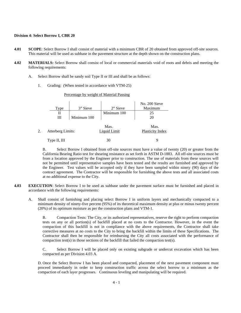
Division 4: Select Borrow I, CBR 20 4.01 SCOPE: Select Borrow I shall consist of material with a minimum CBR of 20 obtained from approved off-site sources.
This material will be used as subbase in the pavement structure at the depth shown on the construction plans. 4.02 MATERIALS: Select Borrow shall consist of local or commercial materials void of roots and debris and meeting the
following requirements:
A. Select Borrow shall be sandy soil Type II or III and shall be as follows:
1. Grading: (When tested in accordance with VTM-25) Percentage by weight of Material Passing
Type 3” Sieve 2” Sieve No. 200 Sieve
Maximum II Minimum 100 25 III Minimum 100 20
Max. Max.
2. Atterberg Limits: Liquid Limit Plasticity Index
Type II, III 30 9
B. Select Borrow I obtained from off-site sources must have a value of twenty (20) or greater from the California Bearing Ratio test for shearing resistance as set forth in ASTM D-1883. All off-site sources must be from a location approved by the Engineer prior to construction. The use of materials from these sources will not be permitted until representative samples have been tested and the results are furnished and approved by the Engineer. Test values will be accepted only if they have been sampled within ninety (90) days of the contract agreement. The Contractor will be responsible for furnishing the above tests and all associated costs at no additional expense to the City.
4.03 EXECUTION: Select Borrow I to be used as subbase under the pavement surface must be furnished and placed in
accordance with the following requirements:
A. Shall consist of furnishing and placing select Borrow I in uniform layers and mechanically compacted to a minimum density of ninety-five percent (95%) of its theoretical maximum density at plus or minus twenty percent (20%) of its optimum moisture as per the construction plans and VTM-1.
B. Compaction Tests: The City, or its authorized representatives, reserve the right to perform compaction tests on any or all portion(s) of backfill placed at no costs to the Contractor. However, in the event the compaction of this backfill is not in compliance with the above requirements, the Contractor shall take corrective measures at no costs to the City to bring the backfill within the limits of these Specifications. The Contractor shall then be responsible for reimbursing the City all costs associated with the performance of compaction test(s) in those sections of the backfill that failed the compaction test(s).
C. Select Borrow I will be placed only on existing subgrade or undercut excavation which has been compacted as per Division 4.03 A.
D. Once the Select Borrow I has been placed and compacted, placement of the next pavement component must proceed immediately in order to keep construction traffic across the select borrow to a minimum as the compaction of each layer progresses. Continuous leveling and manipulating will be required.

4.04 MEASUREMENT AND PAYMENT: Select Borrow I used as subbase for the pavement section will not be measured
by cross-sectioning, but will be based on the plan quantities shown at the locations and depths specified on the pavement summary sheets. Payment will be made based on the contract price per cubic yard as specified in the Unit Price Table.
4-2

5 - 1
Division 5: Select Borrow II, CBR 15 5.01 SCOPE: Select Borrow II shall consist of material with a Minimum CBR of 15 obtained from off-site sources. This
material will be used to replace unsuitable existing material within the roadway when directed and trench for utility construction. All costs of materials, labor, and equipment necessary to excavate, haul, place and compact Select Borrow II to the plan grade shall be included in the contract price specified in the Unit Price Table.
5.02 MATERIALS: Select Borrow shall consist of local or commercial materials void of roots and debris and meeting the
following requirements:
A. Select Borrow II shall be sandy soil Type II or III and shall conform to the following requirements:
1. Grading: (When tested in accordance with VTM-25)
Percentage by Weight of Material Passing
Type 3” Sieve 2” Sieve No. 200 Sieve
Maximum II Minimum 100 25 III Minimum 100 20
Max. Max.
2. Atterberg Limits: Liquid Limit Plasticity Index
Type II 30 9 Type III 30 9
B. Select Borrow II obtained from off-site sources must have a value of fifteen (15) or greater from the California Bearing Ratio test for shearing resistance as explained in ASTM D1883. All off-site sources must be from a location approved by the Engineer prior to construction. The use of materials from these sources will not be permitted until representative samples have been tested and the results are furnished and approved by the Engineer. Test results will be accepted only if they have been sampled within ninety (90) days of the contract agreement. The Contractor will be responsible for furnishing all associated costs for the above tests at no additional expense to the City.
C. Should it be determined that excavation materials for storm drain and utility trenches in the right-of-way are unsuitable for backfilling (Classes III, Type SM and SC, IV & Class V Soil Types listed under USCS Soil Classification System [ASTM D2487]) "Select Borrow shall be furnished and placed by the Contractor at the locations as directed by the Engineer.
5.03 EXECUTION: Select Borrow II to be used as backfill for roadway and trench excavation where unsuitable materials
are encountered shall be furnished and placed in accordance with the following requirements:
A. Backfill shall be evenly and carefully be placed around and over the pipe in six (6) inch maximum layers, each layer being thoroughly and carefully tamped until twelve (12) inches of cover exists over the pipe. Between twelve inches above the pipe and eight inches below the top of the subgrade may be placed and tamped in horizontal layers with the top six inches compacted by the following method. Tamping shall be performed using suitable pneumatic compactors or an approved equal. Compaction equipment specifically designed for these purposes must be present and operational at the job site and shall be utilized throughout the length and depth of the trench to obtain uniform compaction. The degree of compaction and density shall be determined by the VTM-1. Where settlement is important and where excavation has been made through permanent pavement, curbs, and driveways, and sidewalks, or where structures are undercut by excavation, it shall be the Contractor's responsibility to provide compaction of the backfill material to ninety-five percent (95%) of its maximum density at plus or minus twenty percent (20%) of its optimum moisture. Surplus material shall be disposed of by the Contractor. Pavement and shoulders are to be cleaned of excess

5 - 2
material immediately after backfill.
B. Compaction Tests: The City, or its authorized representatives, reserve the right to perform compaction tests on any or all portion(s) of backfill placed at no costs to the Contractor. However, in the event the compaction of this backfill is not in compliance with the above requirements, the Contractor shall take corrective measures at no costs to the City to bring the backfill within the limits of these Specifications. The Contractor shall then be responsible for reimbursing the City all costs associated with the performance of compaction test(s) in those sections of the backfill that failed the compaction test(s).
C. Select Borrow II will be used as directed by the Engineer where existing trench materials are classified as per Division 5.02(C).
5.04 MEASUREMENT AND PAYMENT: Select Borrow II shall include the cost of handling, placing and compacting the
material, and the cost of removing and disposing of the unsuitable material at off-site locations. This item will be measured and paid for as follows:
A. Pipe: Measurement of volume will be determined based on width and depth as defined in this division.
If the nominal pipe diameter exceeds ten (10) inches, the volume will be reduced by the amount displaced by the pipe or portions thereof as determined utilizing outside pipe diameters.
1. Width: The trench width used in determining the volume of select borrow to be paid for shall be the
nominal pipe diameter plus two (2) feet for sewer laterals, water and sewer force mains, and storm drain pipes and culverts. The width for gravity sewers shall be as follows:
Sewer Depth (Plans) Pay Width (Feet) (Feet) Less than or equal to 5 3.0 5 – 7 5.0 7 – 9 5.5 9 – 11 6.5 11 – 13 8.0 Greater than 13 9.5
2. Depth: The trench depth and corresponding stations shall be measured for payment. "Depth" shall be from
the pipe invert or from the top of suitable backfill (whichever is higher) to the finish grade elevation along the centerline of the pipe less the combined thickness of pavement and aggregate base course specified for patching where applicable. Select Borrow II shall be measured at stations for depth at its beginning or ending, at abrupt changes in depth, at changes in pay width, and at intervals not exceeding 50 feet.
B. Measurement for Select Borrow II used in constructing embankments will be measured based on sections comprised of field sections taken after clearing and grubbing, regular excavation, and placement of surplus suitable on-site material compacted to finished plan grades.
C. Select Borrow II shall be paid for at the unit price per cubic yard as per Unit Price Table

6-1
Division 6: Aggregate Base And Subbase Course
6.01 SCOPE: Aggregate Base and Subbase Course shall consist of natural or artificial mixtures of natural or crushed gravel, crushed stone or slag.
6.02 MATERIALS: Aggregate Base and Subbase Course will be designated as Type I and shall consist of crushed stone,
crushed slag or crushed gravel, with or without soil mortar or other admixtures. Crushed gravel shall consist of particles with a minimum of ninety percent (90%) by weight of the material retained on the No. 10 sieve with at least one fractured face by artificial crushing and conforming with the following detailed requirements:
A. Detail Requirements:
1. Grading: Shall conform to the job-mix formula that is selected within the design range and applicable tolerances of Tables II-6 & 8 on pages 131 and 132 of the VDOT Road and Bridge Specifications when tested in accordance with VTM-25.
2. Atterberg Limits: The mean Liquid Limit and Plasticity Index shall be no more than the maximum
allowed by Table II-7 page 132 of the VDOT Road and Bridge Specifications and in accordance with VTM-7.
3. Soundness: The maximum percent of soundness loss will be seven (7) for Freeze and Thaw (20
cycles) and twenty (20) Magnesium Sulphate (5 cycles).
4. Abrasion Loss: Shall be no more than forty-five percent (45%) when tested in accordance with AASHTO T96.
5. Optimum Moisture: Will be limited to plus or minus two percent (2%).
B. Mixing: Subbase or aggregate base materials shall be mixed in an approved central mixing plant of the
pugmill or other mechanical type, unless otherwise specified. The materials shall be blended prior to or during mechanical mixing in such a manner that will insure conformance with the aforementioned detail requirements.
C. The Contractor shall assume responsibility for the quality control and condition of all materials and their
sources. 6.03 EXECUTION: Furnishing, placing and compaction of aggregate base and subbase must be in accordance with the
following conditions:
A. The surface upon which the base or subbase is to be placed shall be prepared in accordance with the applicable Divisions 1, 2, 4 and/or 5 of these Specifications. Any subgrade material which has become wet will be worked, dried and rolled until necessary compaction has been obtained as per 1.02M.
B. Should visual examination reveal that the material in any load is obviously contaminated or segregated, that
load will be rejected without additional sampling or testing of the lot.
C. Equipment used for placement of the aggregate base course or subbase shall be approved prior to performing any such work. Any machine, combination of machines or equipment for spreading, moistening, mixing and compacting which will handle the material without undue segregation and produce the completed base in accordance with these Specifications will be approved.
D. Where the required thickness is more than 6 inches, the material shall be spread and compacted in 2 or more
layers of approximately equal thickness, the maximum compacted thickness of any one layer not to exceed 6 inches. When vibrating or other approved types of special compacting equipment are used, the compacted depth of a single layer of the base course or subbase may be increased to 8 inches upon approval.

6-2
After mixing and shaping, each layer shall be compacted within twenty percent (20%) of its optimum moisture content. The density of each layer of base aggregate material, when compared to the theoretical maximum density as determined in accordance with VTM-1 shall conform to the following:
Percent Plus No. 4 Sieve Material Minimum Percent "D"
0-50 100 51-60 95 61-70 90
The percentages of plus 4 material will be reported to the nearest whole number.
E. Any irregularities in the surface shall be corrected by scarifying, remixing, reshaping and recompacting until a smooth surface is secured. The surface shall thereafter be protected against the loss of fine materials by the addition of moisture, when necessary, and shall be maintained in a satisfactory and smooth condition until accepted by the Engineer. The cost of the addition of moisture will not be a pay item but shall be incidental to the cost of the material.
F. Field density determinations will be performed with a nuclear field density device and/or test loading in
accordance with the requirements of AASHTO T-191, T-205, or T-214. The method of density determination will be as directed by the Engineer. If such tests are specified by the Engineer, and the area tested fails to meet or exceed the minimum acceptable standards of this Division, costs of the tests and corrective measures for the aggregate base or subbase will be borne by the Contractor at no additional expense to the City. If the test(s) should pass all cost(s) shall be paid by the City.
6.04 MEASUREMENT AND PAYMENT: Costs for all materials, labor, and equipment as well as incidental expenses
shall be included in the unit price for furnishing, placing, and compacting the aggregate base and subbase. Aggregate base course and subbase will be measured as the actual square yards in-place and paid at the unit price per square yard at the depth specified in the Unit Price Table.

7 - 1
Division 7: Asphalt Concrete Base Course 7.01 SCOPE: Construction of a Asphalt Concrete Base Course shall consist of one or more layers placed on a prepared
surface in accordance with these Specifications and in close conformity with the alignment and grades shown on the construction plans or established by the Engineer.
7.02 MATERIALS: Asphalt Concrete Base Course shall consist of a combination of mineral aggregates and asphalt
materials mixed mechanically in a plant. Asphalt concrete materials shall meet the following requirements:
A. The materials shall conform to the requirements of VDOT Special Provision for Sec. 212 Asphalt Concrete dated October 11, 1989.
Asphalt concrete mixtures used in surface and intermediate courses shall conform to the following requirements:
MIX DESIGN CRITERIA
MIX TYPE VTM (%)
VFA (%)
MIN. VMA (%)
MINIMUM STABILITY
(lbs.)
FLOW (0.01”)
AC VISCOSITY
GRADE
MARSHALL BLOW
SM-1 4-8 65-80 17 1000 8-16 AC-20 50 SM-2A 3-6 65-80 15 1200 8-14 AC-20 50 SM-2B 3-6 65-80 15 1500 8-14 AC-20 75 SM-2C 4-6 60-75 15 1500 8-14 AC-30 75 SM-3A 3-6 65-80 14 1500 8-14 AC-20 50 SM-3B 3-6 65-80 14 1500 8-14 AC-20 75 SM-3C 3-6 60-75 14 1800 8-14 AC-30 75 1M-1A 3-6 65-80 14 1500 8-14 AC-20 50 1M-1B 3-6 65-80 14 1500 8-14 AC-20 75 BM-1 400 AC-20 50 BM-2 AC-20 BM-3 AC-20 Maximum F/A ratio shall be 1.2:1 on all surface and intermediate mixtures Maximum F/A ratio shall be 1.4:1 on all base mixtures Minimum F/A ratio shall be 0.6:1 on all surface and intermediate mixtures Asphalt content shall be selected at the mid point of VTM range
B. Job-Mix Formula: The Contractor shall submit his source of supply for approval to the Engineer, with a job-mix
formula for each mixture to be supplied for the project prior to starting work. Materials from more than one source shall not be used alternately or mixed when used in base courses without the written consent of the Engineer.
In the event the job-mix formula is modified within a lot, the mean test results of the samples taken will be compared to the applicable process tolerance shown in the following table:
PROCESS TOLERANCE
Tolerance on each Laboratory Sieve and Asphalt Content - Percent Numbe
r Size 1½” ¾” ½” 3/8” No. 4 No. 8 No. 30 No. 50 No. 200 A.C.
1 0.0 ±8.0 ±8.0 ±8.0 ±8.0 ±8.0 ±8.0 ±6.0 ±5.0 ±2.0 ±.60 2 0.0 ±5.7 ±5.7 ±5.7 ±5.7 ±5.7 ±5.7 ±4.3 ±3.6 ±1.4 ±.43 3 0.0 ±4.4 ±4.4 ±4.4 ±4.4 ±4.4 ±4.4 ±3.3 ±2.8 ±1.1 ±.33 4 0.0 ±4.0 ±4.0 ±4.0 ±4.0 ±4.0 ±4.0 ±30 ±2.5 ±1.0 ±.30

7 - 2
8 0.0 ±2.8 ±2.8 ±2.8 ±2.8 ±2.8 ±2.8 ±2.1 ±1.8 ±0.7 ±.21
C. All sources supplying asphalt concrete must, when requested by the Engineer, be able to supply written evidence that they meet or exceed the minimum standards of VDOT Road and Bridge Specifications Sections 212.07, .08, .10, .11, and .12 for Acceptance, Adjustment, Handling and Storing Aggregates, Asphalt Concrete Mixing Plant, and Preparation of Mixtures respectively.
D. Tests for conformance with the Specifications may be made of samples of materials as requested by
the Engineer. All test samples shall meet or exceed the minimum standards of VDOT Special Provision for Sec. 212 Asphalt Concrete dated October 11, 1989 and if said tests fail, costs of tests and corrective measures will be at the Contractors expense with no additional costs to the City.
E. Asphalt Base Course constructed will be as per the type and location shown on the construction plans and shall conform with the following provisions:
1. Asphalt Concrete Base Course currently acceptable to the City are as follows:
a. Type 1M-1A and 1M-1B Asphalt Concrete shall consist of crushed stone, crushed slag or
crushed gravel and fine aggregate, slag, or stone screenings, or combination thereof combined with asphalt cement.
b. Type BM-1 Asphalt Concrete shall consist of local pit material combined with at least 4.0
percent asphalt cement. Addition of mineral filler, not to exceed 5%, or other aggregates will be permitted to conform to specification requirements.
c. Type BM-2 and BM-3 Asphalt Concrete shall consist of coarse aggregate (crushed stone,
crushed slag, or crushed gravel); fine aggregate (slag, stone screenings, gravel screenings, or combination thereof); combined with at least 4.4 percent asphalt cement.
2. The aforementioned Asphalt Concrete Mixtures must fall within the following design ranges: Percentage by Weight Passing Square Mesh Sieves
Type 2 1½ 1 ¾ ½ 3/8 No. 4 No. 8 No. 30 No. 50 No.200
Mix Temp. (at Plant)
IM-1 A-B
100 97-100 72-86 40-58 14-24 3-6 210°-300°F
BM-1 100 85-98 60-80 20-30 1-6 210°-300°F BM-2 100 97-100 75-90 54-74 30-38 3-6 210°-300°F BM-3 100 97-100 80-92 60-74 40-52 14-24 3-6 210°-300°F 7.03 EXECUTION: Asphalt Concrete Base Course shall consist of one or more courses placed on a prepared subbase in
accordance with the applicable divisions of these Specifications for said subbase, and shall meet the following require-ments:
A. Asphalt Concrete mixtures shall conform to VDOT Road and Bridge Specifications Sections 320.03-.08 and
VDOT Special Provisions for Sec. 320 Asphalt Concrete dated December 12, 1989 and November 15, 1990 for Placing Limitations, Equipment, Conditioning of Existing Surfaces, Spreading and Finishing, Compaction, and Joints respectively.
B. When directed, the Contractor shall cut samples from the compacted pavement for testing depth and density as
directed by the Engineer. Construction of Density Control Strips will be required as per VDOT Special Provision for Sec. 320 Asphalt Concrete Pavement dated October 12, 1989 and VTM-10. If said tests fail to meet or exceed the minimum depth of the construction plan or density as per the test method, costs of the tests and corrective measures shall be borne by the Contractor, at no additional expense to the City. However, if the test(s) should

7 - 3
pass all cost(s) shall be paid by the City.
C. Pavement Tolerances in placing and compacting asphalt concrete base course or surface shall be in accordance with VDOT Section 320.10.
7.04 MEASUREMENT AND PAYMENT: Costs of all materials, labor, and equipment as well as
incidental expenses shall be included in the unit price for furnishing, placing, and compacting the asphalt concrete base material and shall be measured and paid as follows:
A. Asphalt concrete will be measured in tons of the type specified, complete in place. Net weight information will be
furnished in the form of individual weight tickets with each vehicle load. B. Each vehicle used to transport asphalt material shall be inspected when it is reported empty and the quantity of
asphalt material remaining therein, if any, shall be gauged and agreed upon as to quantity by representatives of the Owner and Contractor. All asphalt material remaining shall be deducted from the vehicle net weight ticket.
C. Payment will be made at the unit price per ton for each type as specified in the Unit Price Table.

Rev. 2/96 8 - 1
Division 8: Liquid Asphalt Coat
8.01 SCOPE: This work shall consist of preparing and treating the existing asphalt concrete surface with asphalt material (tack coat) in accordance with these Specifications and at the locations shown on the construction plans.
8.02 MATERIALS: Liquid asphalt coat shall consist of an asphalt emulsion and shall conform to the provisions of ASTM
D-8 and the following provisions:
A. Asphalt materials will be purchased on the basis of volume at 60� F. Tank trucks or trailers used to transport asphalt materials shall be equipped with a sampling device. This device shall have an inside diameter of ½" to 1" gate-type valve which shall be built into the tank, with a recirculating or discharge line in such a manner that a sample can be drawn during circulation or discharge. All asphalt materials which are to be stored must be placed in storage tanks that are free from contamination.
B. Asphalt materials for the tack coat shall conform with the applicable sections of VDOT Road and Bridge
Specifications 211.02(b) and (f) for coating ability and asphalt emulsions respectively and to the VDOT Special Provision dated December 13, 1989 Section 313.02.
8.03 EXECUTION: Liquid Asphalt Coat used as a tack coat between an existing asphalt concrete base and the surface
courses shall be applied in accordance with the following provisions:
A. Equipment for heating and applying asphalt material shall conform to VDOT Section 318.04. The maximum application temperature shall conform to Table III-1 pg. 332 of the VDOT Road and Bridge Specifications.
B. The existing surface shall be patched, cleaned, and rendered free of irregularities to the extent necessary to provide
a smooth and uniform surface. The edges of existing pavement shall be cleaned to permit the adhesion of asphalt materials.
C. Tack coat shall not be applied during wet or cold weather or after sunset. It shall be applied in such a manner as to
offer the least inconvenience to traffic and to permit one-way traffic without tracking the material.
D. Tack coat shall be applied as per VDOT Special Provision dated December 13, 1989 Section 313.03.
E. During application, care shall be taken to prevent splattering adjacent areas. The distributor shall not be cleaned or discharged into ditches.
8.04 MEASUREMENT AND PAYMENT: Liquid Asphalt Coat used as a tack coat will not be measured for payment. The
cost for furnishing and applying liquid asphalt material shall be considered incidental to the price per ton for asphalt concrete surface course. The use of a Liquid Asphalt prime coat is not considered necessary if, in the opinion of the Engineer, the subbase is sufficiently moist and well compacted to enhance adhesion of the base. Corrective measures must be taken by the Contractor at no additional cost to the City to ensure proper subbase preparation.
Rev. 2/96 9 - 1
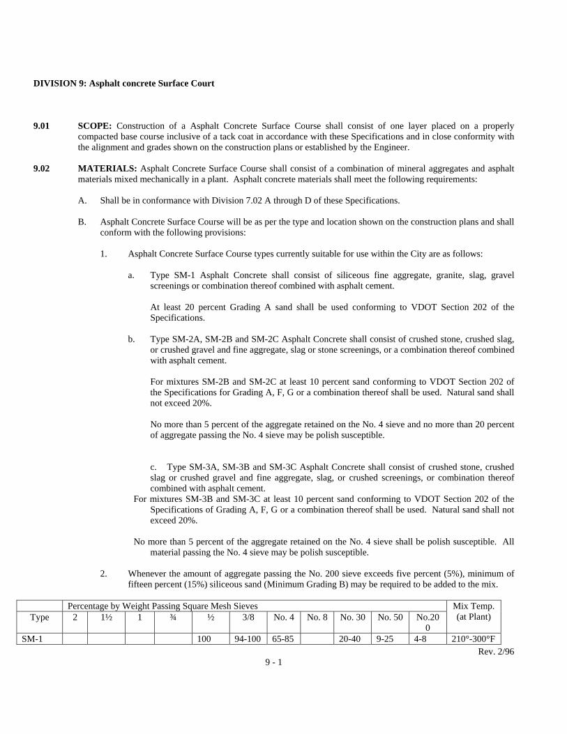
DIVISION 9: Asphalt concrete Surface Court
9.01 SCOPE: Construction of a Asphalt Concrete Surface Course shall consist of one layer placed on a properly compacted base course inclusive of a tack coat in accordance with these Specifications and in close conformity with the alignment and grades shown on the construction plans or established by the Engineer.
9.02 MATERIALS: Asphalt Concrete Surface Course shall consist of a combination of mineral aggregates and asphalt
materials mixed mechanically in a plant. Asphalt concrete materials shall meet the following requirements:
A. Shall be in conformance with Division 7.02 A through D of these Specifications. B. Asphalt Concrete Surface Course will be as per the type and location shown on the construction plans and shall
conform with the following provisions:
1. Asphalt Concrete Surface Course types currently suitable for use within the City are as follows:
a. Type SM-1 Asphalt Concrete shall consist of siliceous fine aggregate, granite, slag, gravel screenings or combination thereof combined with asphalt cement.
At least 20 percent Grading A sand shall be used conforming to VDOT Section 202 of the Specifications.
b. Type SM-2A, SM-2B and SM-2C Asphalt Concrete shall consist of crushed stone, crushed slag,
or crushed gravel and fine aggregate, slag or stone screenings, or a combination thereof combined with asphalt cement.
For mixtures SM-2B and SM-2C at least 10 percent sand conforming to VDOT Section 202 of the Specifications for Grading A, F, G or a combination thereof shall be used. Natural sand shall not exceed 20%.
No more than 5 percent of the aggregate retained on the No. 4 sieve and no more than 20 percent of aggregate passing the No. 4 sieve may be polish susceptible.
c. Type SM-3A, SM-3B and SM-3C Asphalt Concrete shall consist of crushed stone, crushed slag or crushed gravel and fine aggregate, slag, or crushed screenings, or combination thereof combined with asphalt cement.
For mixtures SM-3B and SM-3C at least 10 percent sand conforming to VDOT Section 202 of the Specifications of Grading A, F, G or a combination thereof shall be used. Natural sand shall not exceed 20%.
No more than 5 percent of the aggregate retained on the No. 4 sieve shall be polish susceptible. All
material passing the No. 4 sieve may be polish susceptible.
2. Whenever the amount of aggregate passing the No. 200 sieve exceeds five percent (5%), minimum of fifteen percent (15%) siliceous sand (Minimum Grading B) may be required to be added to the mix.
Percentage by Weight Passing Square Mesh Sieves
Type 2 1½ 1 ¾ ½ 3/8 No. 4 No. 8 No. 30 No. 50 No.200
Mix Temp. (at Plant)
SM-1 100 94-100 65-85 20-40 9-25 4-8 210°-300°F

SM-2 A-B-C 100 97-100 82-94 48-62 18-24 4-7 4-7 210°-300°F
SM-3 A-B-C 100 97-100 72-86 40-59 14-24 3-6 210°-300°F
9.03 EXECUTION: Asphalt Concrete Surface Course shall consist of one course placed on a prepared base in accordance
with the applicable division of these Specifications for said base, and in addition shall meet the provisions of Division 7.03 A-C of these Specifications for asphalt concrete. Surface tolerances shall not exceed 1/4 inch when tested with a ten foot straight edge placed at any two contacts with the surface. All humps or depressions exceeding the specified tolerance shall be corrected or the defective work removed and replaced with new material by the Contractor.
9.04 MEASUREMENT AND PAYMENT: Costs of all materials, labor, and equipment as well as incidental expenses shall
be included in the unit price for furnishing placing, and compacting the asphalt concrete surface material and shall be measured and paid for as follows:
A. Asphalt concrete will be measured in tons of the type specified, complete in-place. Net weight information will be
furnished in the form of individual weight. Tickets provided with each vehicle load. B. Each vehicle used to transport asphalt material shall be inspected when it is reported empty and the quantity of
asphalt material remaining therein, if any, shall be gaged and agreed upon as to quantity by representatives of the City and Contractor. All asphalt material remaining shall be deducted from the vehicle net weight ticket.
C. Payment will be made at the unit price per ton for each type as specified in the Unit Price Table.
D. Maintenance of temporary or final surfaces shall be done by the contractor at no additional cost to the City. This includes all adjustments necessary to meet the surface tolerances specified under 9.03 above.
Rev. 2/96 9 - 2

10-1
Drainage Construction
Division 10: Storm Drain Pipe & Flared End Sections
10.01 SCOPE: Storm drain pipe and flared end sections are to be furnished and installed in accordance with Section 302 of VDOT Road and Bridge Specifications with the following exception:
A. The Contractor shall provide excavation, sheeting, backfill, bracing, joint sealant, erosion control filter
material, dewatering equipment and operations, and other materials, labor, or equipment as needed to properly install the pipe in accordance with the Specifications and good construction practice, without any separate payment for such, to be inclusive and incidental to the price per lineal foot of pipe and the price per each for end sections. The Engineer may direct that the grade of pipe be adjusted up to 1.5' from the plan invert without any additional payment to the Contractor.
B. In addition, pipe installation shall include connecting proposed storm drainage pipe to existing structures that
are shown on the plans to remain in place. Such work shall be performed in reasonably close conformity with the alignment and invert shown on the construction plans.
10.02 MATERIALS: All pipe and end section materials unless otherwise explicitly provided on the plans shall be new and shall be
furnished in accordance with the following requirements:
A. Reinforced Concrete Pipe for Storm Drains and Flared End Sections:
1. Shall conform to the requirements of ASTM Designation C-76 for Reinforced Concrete Culvert and Storm Drain Pipe.
2. Shall conform to the sizes shown on the plans: All pipe for storm drains shall be reinforced concrete
pipe; pipe in the street right-of-way shall be Class III; all others may be Class II unless indicated otherwise on the plans.
3. The Contractor shall use a preformed flexible plastic sealing compound of Butyl Mastic Rope Sealer -
1" size, "EZ Stick" as manufactured by Concrete Products supply or an approved equal for sealing water-tight joints.
B. Corrugated Steel Culvert Pipe, Pipe Arches, and End Sections: This Section is the same as Section 232.02 C-1,
2 of the Virginia Department of Transportation Road and Bridge Specifications with the following modifications and additions:
1. Helically corrugated steel pipe shall be lock seam or welded seam with minimum of two (2) annular corrugations rerolled into each end.
2. Connecting bands shall be standard corrugated bands or hugger type bands which shall engage at least
one (1) annular corrugation for the periphery of the pipe on each side of the joint. Bands are to be asphalt coated in accordance with VDOT Road and Bridge Specifications, Section 232.02 C-1, 2, with a minimum 7" wide neoprene gasket. Corrugated bands shall not be less than 12" wide for pipes with diameters 36 inches to 84 inches inclusive. Dimple bands will not be permitted. Pipe shall be man-ufactured in accordance with VDOT Road and Bridge Specifications, Section 232.02 C-1, 2.

10-2
3. Aluminized Type 2 corrugated steel pipe shall be manufactured in accordance with AASHTO M-274-80 from a base metal manufactured in accordance with ASTM A-526 coated uniformly on both sides with 1.00 oz/sq.ft. of commercially pure aluminum. The pipe, band couplers and fittings shall conform to the requirements of AASHTO M-36. The pipe shall be fabricated with helical corrugations but shall have two annular rerolled corrugations. The pipe shall have a continuous welded seam, utilizing ultrahigh frequency resistance equipment or lockseam.
4. Aluminized Type 2 corrugated steel pipe may be provided with a concrete lining. The concrete shall be
of such consistency as to produce a dense, homogenous lining. The nominal lining thickness shall be a minimum 1/8" over the inside crest of the corrugation. The concrete lining shall have a uniform thickness and a smooth surface and shall be manufactured per ASTM A-849 section 5.3.7. Handling or installation damage to the lining shall be repaired per ASTM A-849 9.1.2 and manufacturer's recommendations.
5. Pipe shall be fully asphalt coated (FC), full coated with paved invert (FCP) or full smooth-interior as
required. Full smooth-interior pipe shall be fully coated and smooth lined on the inside of the pipe so that the corrugations are filled to a minimum thickness of 1/8" over the corrugations. The interior lining shall be applied centrifugally. Asphalt coating shall conform to VDOT Road and Bridge Specifications, Section 232.02 C-1, 2 for material and application.
C. Corrugated Aluminum Culvert Pipe, Pipe Arches and End Sections:
This section is the same as Section 232.02 of the VDOT Road and Bridge Specifications with the following additions:
1. Helically corrugated aluminum pipe and aluminum pipe arch shall be corrugated lock seam or welded
seam. Corrugations shall be in accordance with the plans. 2. No asphaltic coating or paved inverts shall be applied to corrugated aluminum pipe or corrugated
aluminum pipe arches.
3. Connecting bands shall be standard corrugated aluminum bands or hugger type bands which shall engage at least one (1) corrugation for the periphery of the pipe on each side of the joint with a minimum 7" wide neoprene gasket. Corrugated bands shall not be less than twelve (12) inches wide for pipes with diameter 36 inches to 84 inches inclusive. Dimple bands will not be permitted.
4. Corrugated Aluminum Alloy Pipe shall conform to AASHTO Standard Specification M-196.
D. PVC Storm Drainage Pipe: PVC storm drain pipe shall meet the following specifications.
1. Impact Resistance - ASTM D 2444, using 30 lb. TUP B and flat plate holder B the minimum impact
strength shall not be less than 120 ft. lbs. 2. Pipe Stiffness - ASTM D 2412, stiffness shall exceed 10 psi.
3. Gaskets shall be ASTM F477. Only those gaskets and lubricants specified by the pipe manufacturer
shall be used. Under no circumstances shall Vaseline or other petroleum products be substituted as an assembly lubricant.
4. PVC pipe which exhibits discoloration from prolonged storage in direct sunlight may not be used as
this may result in a reduction of the effective service life and material performance under loading.
E. Polyethylene pipe (PE): Polyethylene pipe shall conform to requirements of AASHTO

10-3
Designation M-252 and M-294.
F. Connection to Existing Structure: Any reconstruction of the existing drainage structure required as a result of a connection from a proposed pipe must be with the same type of material used in the original construction and as per Volume II of the City's Public Facilities Manual.
G. Changes in pipe material can occur only at a structure and no more than one change in material shall be made
on a continuous storm drainage system.
H. pH and Soil Resistivity tests must be performed and approved prior to installation of corrugated metal or aluminum pipe if introduced by the Contractor as a material substitution and not previously included on the construction plans, with the Contractor paying all costs for said tests.
I. All pipe joints, except PVC Storm Drainage Pipe, shall be wrapped with a nonwoven erosion control filter material in accordance with Division 30.03A.
10.03 EXECUTION:
A. All pipe and end sections shall be laid true to line and grade proceeding upgrade with the spigot pointing in the direction of flow. The sections of the pipe shall be so laid and fitted together that, when complete, the pipeline will have a smooth and uniform invert, with the full length of the barrel resting on the trench bottom with holes excavated to accommodate pipe bells. The pipe shall be kept thoroughly clean. Each pipe shall be inspected for defects before being lowered into the trench. Water shall not be allowed to rise around the joint until it has been made tight. No more than two hundred (200) feet of trench shall be opened in advance of pipe laying unless permitted by the Engineer. The excavation of trenches shall be fully completed a sufficient distance in advance of the laying of the pipe. The interior of the pipe shall be carefully freed from all dirt or superfluous materials of every description as the work progresses. Pipe joints, except PVC, shall be completely surrounded by a strip of nonwoven erosion control filter material, centered on the joint, with overlap extending from spring line to the opposite spring line. The filter material for concrete pipe shall be a minimum of 2' wide for pipes with a nominal diameter of 24" or less, larger diameters shall have filter material 4' in width. Pipes with connecting bands shall have filter material extending a minimum of 3 inches beyond each side of the band, between it and the pipe. The fabric shall not be installed under the connection band as this results in a poor fit between the pipe and the connection band. The fabric shall be installed and secured in a manner that prevents wrinkles and folds or displacement during backfill operations. All storm drain pipe lift holes shall be covered with a 2' wide strip of filter material of sufficient length to extend to the spring line of the pipe prior to backfilling.
B. After the storm drain and end sections are laid and jointed, it shall be backfilled in accordance with the
following requirements.
1. Backfilling shall be done with material free from large clods and foreign matter, and placed evenly and carefully around and over the pipe in six (6) inch maximum layers, each layer being thoroughly tamped until twelve (12) inches of cover exists over the pipe. The remainder of the backfilling may be placed and tamped in horizontal layers to within eight (8) inches of the finished subgrade elevation. Tamping shall be performed using suitable pneumatic compactors or approved equal. Compaction equipment specifically designed for these purposes must be present and operational at the job site and shall be utilized throughout the length and depth of the trench to obtain uniform compaction. Where settlement is important and where excavation has been made through permanent pavements, curbs, and driveways, and sidewalks, or where structures are undercut by excavation, it shall be the Contractor's responsibility to provide compaction of the backfill material to 95% of its maximum density at plus or minus twenty percent (20%) of its optimum moisture as per VTM-1. All other areas of backfill shall be compacted to provide 90% of its maximum density at optimum moisture. Surplus material shall be disposed of by the Contractor. Pavement and shoulders are to be cleaned of excess material immediately after backfill.

10-4
2. Compaction Tests: The City, or its authorized representatives, reserve the right to perform compaction
tests on any or all portion(s) of backfill placed in the trench at no costs to the Contractor. However, in the event the compaction of this backfill is not in compliance with the specification, Section 10.03. B,1 then the Contractor shall take corrective measures at no costs to the City to bring the backfill within the limits of the Specifications, Section 10.03.B,1. The Contractor shall then be responsible for reimbursing the City all costs associated with the performance of compaction test(s) in those sections of the backfill that failed the compaction test(s). If however the tests should bear out that the backfill is sufficiently compacted, the City will absorb all costs thereof.
3. Permissible construction tolerances between the proposed inverts as shown on the construction plans
and the as-built condition shall not exceed 0.l0'.
4. Special Installation considerations for PVC and PE Storm Drain Pipe:
a. The contractor is responsible for adhering to all manufacturer and ASTM Designation D-2321 installation specifications.
b. General installation methods shall be as specified for flexible pipe in the Virginia Department of
Transportation Road and Bridge Specifications except where these specifications are in conflict with City or manufacturer specifications.
c. Haunching - The haunching area is the most important in terms of limiting the deflection of a
flexible pipe. This is the area that should be compacted to the Proctor density specified in the plans.
d. Initial Backfill - Initial backfill begins at the haunch of the pipe to a plane 6 inches to 12 inches above the pipe. Under shallow cover conditions the backfill must be compacted to the specified proctor density up to the pavement section or finished grade. All compaction must be completely achieved during placement of backfill material.
e. If compaction equipment is used to prepare the bedding and backfill for the road surface, it
should not be used within 3 feet of the top of the pipe and then only if the pipe zone soil density has been previously compacted to a minimum 85% standard Proctor density.
f. Pipe Zone Materials - Pipe zone materials include the materials in the haunching area and the
initial backfill. They must meet plan specifications.
g. Compaction Techniques - Flooding or jetting are not acceptable compaction methods. All compaction must be obtained by mechanical or hand tamping methods as specified in the Virginia Department of Transportation Road and Bridge Specifications Section 302.
h. Backfill materials and the specified Proctor density of the haunching and backfill materials may
be checked by an independent soils engineering firm at the City's option.
i. The City reserves the right to test flexible pipe for excessive deflection. Deflection may not exceed 5% of the minimum diameter as specified in ASTM D 3034.
j. For PVC Pipe installed under shallow cover conditions, (3 feet or less) Virginia Department of
Transportation size 57 angular stone must be used in the bedding, haunching and backfill areas up to the top of the pipe. A minimum 95% proctor density is required.
k. P.E. Pipe shall be installed in accordance with ASTM D-2321 except that bedding and backfill
shall be VDOT type 57, 25 or 26 stone where the pipe is underneath the pavement. In “behind

10-5
the curb” installations backfill and bedding shall be select material or in accordance with AASTO M145 Group A-1, A-2-4, A-2-5, A-2-6 or A-3 (GW, GP, SW, GM and SM) only. Polyethylene storm pipe shall be installed in accordance with VDOT PB-1. Bedding and backfill material shall be compacted to 95% proctor density and shall extend 6" below, 24" laterally and 12" above the pipe.
l. Uncovered pipe may not be left in an open trench at the end of the work day. All pipe that has
been placed in the open trench must be properly bedded and backfilled in order to prevent wash out or flotation from over night rainfall.
10.04 MEASUREMENT AND PAYMENT:
A. Reinforced Concrete Pipe for Storm Drains: The length of pipe completed and accepted will be field measured from center of drainage structure to center of drainage structure.
The length so determined will be paid for at the unit price bid per lineal foot for the size specified in the Proposal.
B. Corrugated Steel Pipe for Storm Drains: Same as 10.04 A.
C. Corrugated Aluminum Pipe for Storm Drains: Same as 10.04 A. D. PVC and PE Storm Drain Pipes: Same as 10.04A. Special installation considerations for PVC and PE Storm
Drain Pipe will not be measured and paid as such, but will be incidental to the lineal foot price of the PVC or PE Storm Drain Pipe.
E. Connections to existing drainage structures will not measured and paid as such, but will be incidental to the
lineal foot price of the incoming storm drainage pipe. F. Flared end sections shall be measured and paid for at the contract price per each at the diameter specified in the
Unit Price Table. G. Erosion control filter material for pipe joints will not be measured and paid as such, but will be incidental to
the lineal foot price of storm drain pipe.

11 - 1
Division 11: Catch Basins, Manholes, Conflict Manholes & Drop Inlets 11.01 SCOPE: The Contractor shall furnish all materials, equipment and labor necessary to construct catch basins, manholes,
conflict manholes, and drop inlets in accordance with the applicable construction details of Volume II of the City of Chesapeake Public Facilities Manual and the materials and construction methods of Section 302 of the VDOT Road and Bridge Specifications.
11.02 MATERIALS: All materials shall be new and shall be furnished as per Section 302.02 of the VDOT Road and Bridge
Specifications, with the following additional requirements:
A. Brick: ASTM C-32, GRADE MA B. Frames and Covers: Shall be of good quality cast iron of uniform grade, Federal Spec. QQ1-652. Manhole
frames to be in accordance with VDOT Standard MH-1. Drop inlet and catch basin frames shall be as per Richards Foundry J-1010 and H-109 designations respectively or approved equal.
C. Steps: Shall be #6 galvanized rebar, #3 grade 60 rebar encased in a corrosion resistant rubber or aluminum in
accordance with ASTM B22, Alloy 6005-75 and within the dimensions and guidelines of the Chesapeake Standard ST-1.
D. CONCRETE FOR INVERT SLABS: Air entrained Portland Cement Concrete (A3) having a minimum twenty-
eight (28) day compressive strength of 3000 psi in accordance with Section 216 Class A3 Concrete.
E. Mortar:
1. Portland Cement: ASTM C50, Type 1.
2. Sand: Clear, sharp, graded from fine to coarse, ASTM C-144.
3. Water: Clean and potable.
4. Mixture: One (1) part cement, two (2) parts sand.
F. Reinforced Precast Structures: Shall be manufactured in accordance with ASTM Des. C-478 with an eccentric or concentric cone or flat slab tops. Shop drawings must be submitted for approval to the Engineer or certified as conforming to current City standards. Joints shall be water-tight. Precast sections shall be fabricated to provide a tongue and groove joint sealed with performed flexible plastic sealing compound, Butyl Mastic Rope Sealer - 1" size, "EZ Stick" as manufactured by Concrete Products Supply or an approved equal. Joints shall be plastered inside and outside of the manhole with a cement grout. (Grout mixture shall be as per Mortar above.)
G. Curing Materials: Shall consist of waterproof paper, polyethylene sheeting, liquid membrane seal or water in
accordance with VDOT Sections 220.
H. Reinforcing Steel: Shall be grade 40 or 60 and conform to VDOT Section 223.
I. Portland Cement Concrete: Shall be class A-3 concrete and in accordance with AASHTO M-85 and AASHTO M-154 for air-entraining admixtures.
11.03 EXECUTION:
A. The Contractor shall provide such excavation, sheeting backfill, bracing, dewatering equipment and operations,
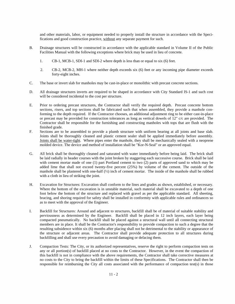
11 - 2
and other materials, labor, or equipment needed to properly install the structure in accordance with the Speci-fications and good construction practice, without any separate payment for such.
B. Drainage structures will be constructed in accordance with the applicable standard in Volume II of the Public
Facilities Manual with the following exceptions where brick may be used in lieu of concrete.
1. CB-1, MCB-1, SDI-1 and SDI-2 where depth is less than or equal to six (6) feet.
2. CB-2, MCB-2, MH-1 where neither depth exceeds six (6) feet or any incoming pipe diameter exceeds forty-eight inches.
C. The base or invert slab for manholes may be cast-in-place or monolithic with precast concrete sections. D. All drainage structures inverts are required to be shaped in accordance with City Standard IS-1 and such cost
will be considered incidental to the cost per structure.
E. Prior to ordering precast structures, the Contractor shall verify the required depth. Precast concrete bottom sections, risers, and top sections shall be fabricated such that when assembled, they provide a manhole con-forming to the depth required. If the Contractor chooses, an additional adjustment ring to be either cast-in-place or precast may be provided for construction tolerances as long as vertical dowels of 12" c/c are provided. The Contractor shall be responsible for the furnishing and constructing manholes with tops that are flush with the finished grade.
F. Sections are to be assembled to provide a plumb structure with uniform bearing at all joints and base slab. Joints shall be thoroughly cleaned and plastic cement sealer shall be applied immediately before assembly. Joints shall be water-tight. Where pipes enter the manhole, they shall be mechanically sealed with a neoprene molded device. The device and method of installation shall be "Kor-N-Seal" or an approved equal.
G. All brick shall be thoroughly cleaned and saturated with water immediately before being laid. The brick shall
be laid radially in header courses with the joint broken by staggering each successive course. Brick shall be laid with cement mortar made of one (1) part Portland cement to two (2) parts of approved sand to which may be added lime that shall not exceed twenty-five percent (25%) by volume of the cement. The outside of the manhole shall be plastered with one-half (½) inch of cement mortar. The inside of the manhole shall be rubbed with a cloth in lieu of striking the joint.
H. Excavation for Structures: Excavation shall conform to the lines and grades as shown, established, or necessary.
Where the bottom of the excavation is in unstable material, such material shall be excavated to a depth of one foot below the bottom of the structure and replaced with gravel as per the applicable standard. All sheeting, bracing, and shoring required for safety shall be installed in conformity with applicable rules and ordinances so as to meet with the approval of the Engineer.
I. Backfill for Structures: Around and adjacent to structures, backfill shall be of material of suitable stability and
perviousness as determined by the Engineer. Backfill shall be placed in 12 inch layers, each layer being compacted pneumatically. No backfill shall be placed against a structural wall until all connecting structural members are in place. It shall be the Contractor's responsibility to provide compaction to such a degree that the resulting subsidence within six (6) months after placing shall not be detrimental to the stability or appearance of the structure or adjacent areas. The Contractor shall provide adequate protection to all structures during backfilling and shall use every precaution to avoid damaging or defacing them.
J. Compaction Tests: The City, or its authorized representatives, reserve the right to perform compaction tests on
any or all portion(s) of backfill placed at no costs to the Contractor. However, in the event the compaction of this backfill is not in compliance with the above requirements, the Contractor shall take corrective measures at no costs to the City to bring the backfill within the limits of these Specifications. The Contractor shall then be responsible for reimbursing the City all costs associated with the performance of compaction test(s) in those

11 - 3
sections of the backfill that failed the compaction test(s). 11.04 MEASUREMENT AND PAYMENT:
A. Catch basins and drop inlets will not be measured but will be paid for at the contract price per each for the type as specified in the Unit Price Table.
B. Manholes will be paid for at the contract unit price per each at the depth increments as follows:
Less than 5' 5’ – 7’ 7’ – 9’
9’ – 11’ 11’ – 13’
Greater then 13’
No separate payment will be made for frames and covers, which will be considered incidental to the contract price per each as specified in the Unit Price Table.
C. Payment for Conflict manholes shall include the cast iron pipe passing through the manholes. Conflict
manholes shall be measured and paid at the contract price per each specified in the Unit Price Table. D. All materials, equipment, and labor required to conform with Division 11.03 A & D will be considered
incidental to the several contract prices for storm drainage structures as specified in the Unit Price Table.
E. Junction boxes will not be measured but will be paid for at the contract price for each as per the Unit Price Table.
F. No adjustment in the unit bid price is allowed for increases or decrease of less than one (1) foot in the depth of
the structure from that shown on the plans.

12 - 1
Division 12: Box Culvert Concrete, Headwalls, & Endwalls 12.01 SCOPE: The Contractor shall furnish all materials, equipment, and labor necessary to construct concrete box culverts,
headwalls, and endwalls in accordance with these Specifications, the lines and inverts on the construction plans and good construction practice.
12.02 MATERIALS:
A. Fine Aggregate: Natural sand or stone sand shall consist of sound particles of Grade A stone that meet or exceed the minimum requirements for grading, soundness, organic impurities, void content and deleterious material percentage in accordance with VDOT Road and Bridge Specifications Section 202.01 through .03.
B. Coarse Aggregate: Coarse aggregate shall consist of crushed stone, crushed slag, or crushed or uncrushed
gravel that meets or exceeds the minimum requirements of VDOT Road and Bridge Specifications Section 203.01 through .03 for grading, soundness, abrasion loss, or percent deleterious material.
C. Portland Cement: Portland Cement shall conform to AASHTO M85 with the following exception:
The sulfur trioxide content as per ASTM C-150 will be permitted, provided the supporting data specified in ASTM C-150 is submitted to the City for review and acceptance prior to use.
D. Water: Water used with cement shall be clean, clear, and free of oil, acid, salt, alkali, organic material or
other deleterious substances. Water which has been approved for drinking will be accepted for use in concrete without testing.
E. Concrete Admixtures: If admixtures are not specified in the plans or contract documents, the Contractor
must request approval in writing from the Engineer prior to its use. Accelerating admixtures, water-reducing and retarding admixtures, and air entraining admixtures must conform to AASHTO Specifications M-194 Type C or E, M-194 Type D, and M-154 respectively.
F. Portland Cement Concrete: Shall be VDOT designation Class A3,General use Concrete, air entrained, (3000
psi minimum compressive strength at 28 days). 12.03 EXECUTION:
A. In the event it is necessary to temporarily relocate an existing stream or drainage facility for the installation of a pipe or box culvert, the Contractor shall design and provide temporary channels or culverts of adequate size to carry the normal flow of the stream or drainage facility. Normal flow will be determined by the Engineer prior to construction or installation of the channel or culvert.
The Contractor shall submit his temporary relocation design to the Engineer for review and acceptance in sufficient time to allow for discussion and any correction(s) prior to beginning the work which the design covers. All costs for the temporary relocation of the stream or drainage facility shall be included in the cubic yards contract price specified in the Unit Price Table.
B. All form work shall be constructed and erected in accordance with the appropriate provisions of VDOT Road
and Bridge Specifications Section 404.03 for steel or wood forms. C. All false work shall be designed and constructed to provide the necessary rigidity and to support the
construction loads without appreciable settlement or deformation. A dead load of 150 pcf will be assumed for concrete. The Contractor will be required to employ screw jacks or wedges to compensate for any settlement

12 - 2
of the forms prior to or during concrete placement.
D. Placement and Consolidation: The Contractor is required to place and consolidate the concrete within the forms based on the requirements of VDOT Road and Bridge Specifications Section 404.03 (l)
E. Construction Joints: Construction joints shall be made only as shown on the plans or as specified herein.
Construction joints against which earth fill is to be placed shall be protected by a heavy coat of asphalt conforming to ASTM D312 Type II. When construction joints are exposed to view or where water seepage is possible, a waterstop acceptable to the Engineer must be installed. It must be placed a minimum of two inches into the concrete and no more than three inches away from the joint. In order to bond successive courses, keys constructed of beveled woodstrips must be inserted prior to concrete placement and subsequently removed.
F. Concrete Exposed to Tidal Water: Concrete box culverts with construction joints located within a zone five
feet above and/or below the mean tide elevation are subject to a prolonged time period of 48 hours for form removal. In addition five days of drying time and the application of one coat of primer and four coats of asphalt or one coat of Epoxy Type EP-3B followed by one coat of Epoxy Type EP-3T shall be required. The coatings for pre-cast concrete must be identical to the above guidelines.
G. Form Removal: The time of removal for forms will be controlled by test cylinder results that meet or exceed
the minimum requirements of Table IV-2 of Section 404.03 of the VDOT Road and Bridge Specifications.
H. Curing of Concrete: Concrete curing methods shall be subject to approval by the Engineer prior to use. When the temperature is above 40� F in the shade, exposed concrete surfaces must be cured before the sheen disappears from the fresh concrete curing shall be maintained for seven days. White polyethylene sheeting shall be used between April 1 and November 1 and opaque sheeting at other times. Liquid membrane, if used, must be applied at a rate of one gallon per 150 to 200 square feet depending upon roughness of concrete. In the event the atmospheric temperature drops below 40� F after concrete placement, insulated blankets and/or heaters must be provided by the Contractor at no additional cost to the City to maintain the concrete mass at 50� F for not less than 72 hours. In no event will the City allow placement of concrete when the temperature in the shade is less than or equal to 40� F.
I. Protection of Concrete: The Contractor is responsible for protection of the concrete following placement from
weather or construction activities and will be held financially accountable for any damage incurred.
J. Opening of Traffic: Structures shall not be opened to construction traffic until the 28 day minimum compressive strength is obtained.
K. Finishing Concrete Surfaces: All defective areas produced by form ties, honeycomb, spalls, or broken corners
and edges must be filled with mortar conforming to Sections 218 and 404.07 of VDOT Road and Bridge Specifications. After removal of forms all endwalls, headwalls and/or wingwalls must be rubbed with a carborundum stone until all form marks, projections, and irregularities have been removed.
L. Slump Control: All box culvert concrete shall be placed at a slump of three (3) inches to four (4) inches.
M. Precast box culverts and endwalls shall be built, measured, and paid for in accordance with these specifications
with the exception that 4000 psi concrete be used. Shop drawings must be submitted to the Engineer for review or approval or certifications must be provided stating that they conform with current Chesapeake standards.
N. Test Cylinders: Form removal and forming for and placing concrete in super imposed elements are controlled
by cylinder tests, the Contractor will be permitted to perform these operations when the cylinder strengths reach the values indicated in Table IV-2, page 425 of the VDOT Road and Bridge Specifications. The cylinders shall be cured under conditions which are not more favorable than the most unfavorable conditions

12 - 3
for the portions of the concrete which the cylinders represent. The Contractor shall furnish the molds, labor and material for all such test specimens and shall make as many as he feels necessary and shall be responsible for transporting specimens to the testing facility. Single-use waxed paper, plastic or light gauge metal molds, conforming to AASHTO M205, may be used for making control cylinders. Control cylinders shall be made under the observation of the Engineer. Tests for compressive strength will be made by representatives of the supplier with certified documentation furnished to the Engineer of the test results, at no additional cost to the City.
12.04 MEASUREMENT AND PAYMENT:
A. Concrete for box culverts will not be field measured but will be based on plan quantities. Class A3 Concrete for Box Culverts will paid based on the contract price per cubic yard as specified in the Unit Price Table.
B. Headwalls, endwalls, wingwalls, and aprons will not be measured but will be paid for at the contract price per
each as specified in the Unit Price Table. Form work, rebar, and other materials required for its construction in accordance with these Specifications and the plans will be considered incidental to the price per each.

13 - 1
Division 13: Reinforcing Steel (Box Culvert) 13.01 SCOPE: The Contractor shall be required to furnish all materials, equipment, and labor necessary to place all reinforcing
steel in accordance with VDOT Road and Bridge Specifications Section 406 unless otherwise listed below and in close conformity with the plans.
13.02 MATERIALS: All bars over ¼ inch in diameter will be deformed and shall conform to VDOT Specification Section 223 for
steel reinforcement. 13.03 EXECUTION: All work associated with furnishing and placing reinforcing steel shall be as shown on the construction plans
or referenced standards and in accordance with VDOT Road and Bridge Specifications Section 406 with the following additions and/or modifications.
A. Ten (10) copies of reinforcing steel shop drawings must be submitted to the City for their review and approval
if said drawings do not conform with accepted City or VDOT standards. B. If field cutting of rebar is required, this shall be done by saw cutting only.
13.04 MEASUREMENT AND PAYMENT: Reinforcing steel will be measured in pounds of steel in-place. Quantities will be
based on those shown on the plans or referenced City or VDOT Standards. Payment will be based on the contract price per pound as specified in the Unit Price Table.

14 - 1
Division 14: Bedding Material (Box Culvert) 14.01 SCOPE: The Contractor shall be required to furnish all material, labor, and equipment necessary to place bedding material
for box culvert construction at the locations and depths shown on the plan and in accordance with the following provisions.
14.02 MATERIALS: Crusher run aggregate shall be size number 25,26 or 57 and consist of crushed stone, slag, or crushed gravel
and conform with Sections 205 of the VDOT Road and Bridge Specifications for Grading, Atterberg Limits, Soundness, and Abrasion Loss.
14.03 EXECUTION: Bedding Material shall be placed in a trench relatively free of water on top of acceptable local material or
Select Borrow II if shown on the plans or specified by the Engineer. Bedding material shall be lightly and uniformly compacted and will not be subject to the requirements of Section 7 of the General Conditions Part II for increased or decreased quantities.
14.04 MEASUREMENT AND PAYMENT: Bedding material for box culverts shall be field measured at the square yards in
place at the depth shown on the plans or directed by the Engineer. If additional depths of bedding material are required it will be increased by the Engineer at six (6)inch intervals. Increased depths resulting from field changes will increase the unit price quantities linearly. Payment will be made at the contract price for square yards per depth as specified in the Unit Price Table. Bedding material placed outside the limits shown on the plans or specified by the Engineer will not be measured. Bedding material for headwall and endwall construction when specified on the construction plans or directed by the Engineer in the field will not be measured and paid for as such, but will be considered incidental to the price per each as per the Unit Price Table.

15 - 1
Division 15: Minor Structure Excavation (Box Culvert) 15.01 SCOPE: The Contractor shall be required to furnish all labor and equipment necessary to satisfactorily remove and dispose
of all materials necessary to accommodate box culvert construction as shown on the plans. 15.02 EXECUTION: Minor structure excavation shall include all excavation required to remove in-place material to the locations
and inverts shown on the plans for construction of the box culvert. In addition it includes disposal of all unsuitable material, pumping, sheeting, and dewatering of the trench and backfilling and compacting with either regular excavation or select fill to the existing ground elevation. The following requirements will apply for work to be performed under minor structure excavation.
A. Material deposited within the stream area from foundation or other excavation shall be removed and the stream
area freed from all obstructions caused by the Contractor's operations. The Contractor shall exercise every reasonable precaution throughout the duration of the project to prevent erosion of the soil and the pollution and siltation of rivers, streams and lakes.
B. Regular excavation may be used for backfill if the material substantially conforms with Division 4 of these
Specifications for Select Material Type I, and 100% of the material passes the three inch sieve.
C. Backfill and compaction shall be advanced simultaneously on both sides of the box culvert. The fill above the top of the box culvert shall be completed as specified for regular excavation.
D. Backfill shall be placed along the box culvert in uniform layers and shall be thoroughly compacted within 95%
of its maximum density at (±) 20% of its optimum moisture as per VTM-1. Each layer shall be compacted by rolling, tamping with mechanical rammers, or by hand tamping with heavy metal tampers.
E. Compaction Tests: The City, or its authorized representatives reserve the right to perform compaction tests on
any or all portion(s) of backfill placed in the trench at no costs to the Contractor. However, in the event the compaction of this backfill is not in compliance with the Specification, Section 2.03.C, then the Contractor shall take corrective measures at no costs to the City to bring the backfill within the limits of the Specifi-cations, Section 2.03.C. The Contractor shall then be responsible for reimbursing the City all costs associated with the performance of compaction test(s) in those sections of the backfill that failed the compaction test(s). If however the tests should bear out that the backfill is sufficiently compacted, the City will absorb all costs thereof.
15.03 MEASUREMENT AND PAYMENT:
A. The contract prices specified in the Unit Price Table shall include full compensation for all labor, equipment, and materials necessary to remove and dispose of all unsuitable material as well as furnish, place and compact backfill material. Minor structure excavation required to construct headwalls and endwalls or to install storm drainage pipes and pipe culverts will not be measured but considered incidental to the contract price for each item specified in the Unit Price Table.
B. Minor structure excavation for box culverts will not be measured in-place but will be based on the plan
quantity for the location and elevation shown on the plan or directed in the field by the Engineer. Payment will be made based on the contract price per cubic yard as specified in the Unit Price Table.

16 - 1
Division 16: Bedding Material (Drainage and Utility pipe) 16.01 SCOPE: Contractor must furnish all materials, equipment, and labor necessary to undercut and replace with aggregate
as per the Specifications or as directed by the Engineer.
16.02 MATERIALS: Select bedding stone shall consist of coarse aggregate conforming to the VDOT Road and Bridge Specifications Section 203, Size 57, for drainage construction and size 57, smooth river rock for utility construction.
16.03 EXECUTION:
A. Should unsuitable material (Class III Type SM, SC, IV soil types as per USCS Soil Classification System ASTM
D-2387) be encountered at the bottom of the pipe trench, such soil shall be removed to a width and depth specified by the Engineer and replaced with select bedding stone.
B. All unsuitable material is to be disposed of offsite after all necessary permits and property rights have been
obtained.
16.04 MEASUREMENT AND PAYMENT:
A. The width of select bedding stone will be based on the inside pipe diameter plus two (2) feet. The depth required will be six (6) inches for pipes less than forty-eight (48) inches and one (1) foot for larger pipe sizes or as determined by the Engineer.
B. Select bedding material when authorized by the Engineer will be measured based on square yards in place and at
the contract price per square yard at both the six (6) and twelve (12) inch depths shown in the Unit Price Table. Select materials placed outside of the limits described in 16.04 (A) will not be measured.
C. The contract prices specified in the Unit Price Table shall include full compensation for all labor, equipment, and
materials necessary to remove and properly dispose of all unsuitable soil as well as furnish and place the select bedding material.

17 - 1
Division 17: Sand Cement Bag Rip-Rap & Ditch Regrading 17.01 SCOPE: Contractor shall furnish all labor, materials and equipment, necessary for the construction of sand cement rip-
rap in bags and regrading existing ditches as shown on the construction plans.
17.02 MATERIALS: The Contractor shall furnish all new materials in accordance with the following:
SAND CEMENT RIP-RAP IN BAGS: Shall be dry-mix in accordance with VDOT Road and Bridge Specifications Section 414.03(g)2.
17.03 EXECUTION:
A. Sand cement rip-rap in bags shall be installed at locations and in accordance with City Standard EC-2 of the
Public Facilities Manual, Volume II.
B. All widening, regrading, and cutting of slopes to existing ditches will be at the locations and in accordance with the cross-sections and limits shown on the plans.
C. All erosion and sediment controls must be in place in accordance with Division 23 of these Specifications.
D. In Site Plan or Subdivision Development all existing interior and perimeter ditches shall be cleaned and graded to
provide a positive grade and prevent standing water prior to acceptance.
17.04 MEASUREMENT AND PAYMENT:
A. Sand cement rip-rap in bags shall be measured by the square yard of surface area in place as per the depth indicated on the construction plans and specified in the Unit Price Table per square yard per depth category.
B. Ditch widening, regrading, and cutting of slopes will not be measured and paid for as such. The cost of
widening, regrading, and cutting of slopes to existing ditches will be included in the lump sum price for "Ditch Regrading."
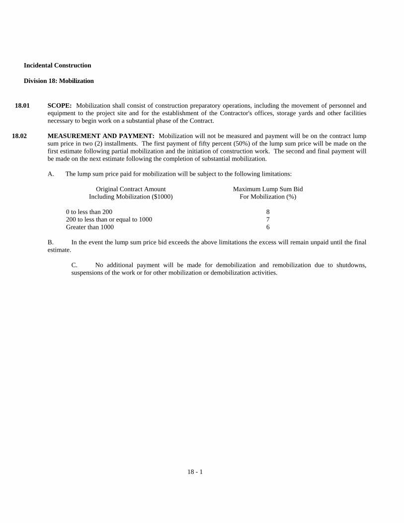
18 - 1
Incidental Construction
Division 18: Mobilization 18.01 SCOPE: Mobilization shall consist of construction preparatory operations, including the movement of personnel and
equipment to the project site and for the establishment of the Contractor's offices, storage yards and other facilities necessary to begin work on a substantial phase of the Contract.
18.02 MEASUREMENT AND PAYMENT: Mobilization will not be measured and payment will be on the contract lump
sum price in two (2) installments. The first payment of fifty percent (50%) of the lump sum price will be made on the first estimate following partial mobilization and the initiation of construction work. The second and final payment will be made on the next estimate following the completion of substantial mobilization.
A. The lump sum price paid for mobilization will be subject to the following limitations:
Original Contract Amount Maximum Lump Sum Bid
Including Mobilization ($1000) For Mobilization (%)
0 to less than 200 8 200 to less than or equal to 1000 7 Greater than 1000 6
B. In the event the lump sum price bid exceeds the above limitations the excess will remain unpaid until the final estimate.
C. No additional payment will be made for demobilization and remobilization due to shutdowns, suspensions of the work or for other mobilization or demobilization activities.

19 - 1
Division 19: Clearing & Grubbing 19.01 SCOPE: The work in this section shall consist of furnishing all labor, material, equipment and other incidentals to
perform the work necessary for clearing and grubbing in accordance with the Contract Documents.
19.02 EXECUTION:
A. The Contractor shall clear and grub all areas within public easements or rights of way as shown on the approved plans. Clearing shall include felling all standing trees, except where designated by the Engineer to remain, and cutting of all brush. Grubbing shall include removal of all stumps. Roots shall be removed to a depth not less than 18" below subgrade. The work also includes complete removal and disposal of all felled trees, brush and stumps, etc. In addition, any depressions resulting from the above removals must be backfilled to the original ground elevation. This work shall be done in strict accordance with local, state, and federal laws controlling open burning. Prior approval and coordination must be handled by the Contractor with the City of Chesapeake Fire Department.
B. Existing trees that are designated to be retained after construction shall be protected during construction in the
following ways, and as per Virginia Erosion and Sediment Control Standard Specifications 1.85.
1. Prior to any clearing, grading or construction, protective barriers shall be placed around all trees to be retained on the site to prevent the destruction or damage of trees. These will be located in a circular pattern with a radius equal to the length of the widest or longest branch. Material will not be stockpiled within this defined area and vehicles and other equipment are to be excluded from this area to avoid soil compaction. The only exception to this requirement will be those specifically allowed by these standards and specifications.
2. Boards or wires of a non-protective nature will not be nailed or attached to trees during building
operations.
3. Heavy equipment operations will be cautioned to avoid damage to existing tree trunks, and roots during land leveling operations. Feeder roots should not be cut in an area equal to twice the tree circumference (measured 4-1/2' above ground in inches). Expressed in feet. (Example - circumference of ten inches would have a "no cut" zone of twenty feet in all directions from the tree). This should apply to ditching for all utilities services, if feasible.
4. All roots severed or severely damaged during building or land leveling shall be trimmed to remove
damaged or splintered area. Exposed roots should be covered and moistened immediately after exposure.
5. All tree limbs damaged during building or land leveling, or removed for any other reason, will be sawed flush to tree trunk.
19.03 MEASUREMENT AND PAYMENT: Clearing and grubbing will not be measured and paid for as such. The cost of
clearing and grubbing will be a lump sum price under said name in the Unit Price Table.

20 - 1
Division 20: Topsoil & Seeding and Restoration 20.01 SCOPE: All graded and unpaved areas within the limits shown on the plans shall be topsoiled, limed, fertilized, seeded
and mulched in accordance with the requirements listed below as well as any areas outside the limits of construction disturbed by the Contractor. Topsoil and Seeding will be performed as a lump sum bid price for general roadway and bridge construction. For storm drainage, water, gravity sewer and forcemain contracts restoration will be paid for on a lineal foot basis along the center line of the pipe installation and performed under the guidelines of this division.
20.02 MATERIALS: The Contractor shall furnish all materials in accordance with the following:
A. Topsoil: Shall conform to the requirements of Section 244.02(b) for Classes A & B Topsoil of the VDOT Road
and Bridge Specifications except that both Classes A & B shall be free from subsoil, stump roots, brush, stones, clay lumps or similar objects larger than one inch in diameter.
B. Lime: Dolomite agricultural ground limestone containing at least 85% of total carbonates and ground to such
fineness that at least 50% will pass a 100 mesh sieve and at least 90% will pass a 30 mesh sieve.
C. Commercial fertilizer shall be 10-10-10 formula, and shall conform to all applicable State fertilizer laws. It shall be delivered to the site in the original unopened containers, each bearing the manufacturer's guaranteed analysis.
D. Seed: Shall conform to the following mixtures and time schedule:
HULLED UNHULLED ANNUAL
DATE FESCUE BERMUDA BERMUDA RYE GRASS 2/1 – 5/1 65 lbs/ac 35 lbs/ac 5/2 – 8/1 35 lbs/ac 65 lbs/ac 8/2 – 11/15 65 lbs/zc 35 lbs/ac 11/16 – 1/31 55 lbs/ac 25 lbs/ac 20 lbs/ac
No Changes in the seed mixture may be made without prior approval of the Engineer.
E. Mulch: Shall be dry, threshed straw of wheat, oats, barley or rye, and other materials approved by the Engineer.
20.03 CONSTRUCTION METHODS:
A. Topsoil: Shall be furnished in accordance with Paragraph 20.02, A, and placed at a thickness in accordance with
the requirements of VDOT Road and Bridge Specification Section 602.03. B. Seeding materials shall be furnished in accordance with Paragraph 20.02,B, C, D, and E, herein, and shall be
placed in accordance with the requirements of Section 603.03 VDOT Road and Bridge Specifications.
20.04 METHOD OF MEASUREMENT AND BASIS OF PAYMENT: Topsoil and seeding will not be measured but will be paid on a lump sum basis only. Restoration will not be measured but paid for on a lump sum basis as per the Unit Price Table. Area's measured as pavement patching will not be included in restoration. If swales are required over the storm drainage line as per the plans, these swales for local drainage will not be measured for payment and will be considered incidental to the lineal foot price for restoration.
Topsoil shall be stripped from the areas to be excavated or graded and may be stockpiled in approved locations. Upon completion of backfilling or grading, topsoil shall be spread over disturbed areas as indicated on the plans to a minimum depth of two (2) inches. Where topsoil does not exist, the Contractor shall furnish an amount sufficient to cover the site to a minimum depth of two (2)inches. Topsoil available within excavated areas may be used.

21 - 1
Division 21: Pavement Patching
21.01 SCOPE: The Contractor shall furnish all labor, materials, equipment and supplies, and shall perform all work necessary for the replacement of paved surfaces as shown on the plans and specified herein. This work shall be in accordance with the VDOT Road and Bridge Specifications unless otherwise provided in the following division.
21.02 MATERIALS: Materials for pavement patching shall be furnished by the Contractor in accordance with Divisions 4
thru 9 of these specifications.
21.03 EXECUTION:
A. General:
1. Paved surfaces necessary to be removed or disturbed in order to perform the installation of water, sewer and storm pipelines and private utilities shall be restored in accordance with the requirements specified herein or shown on the plans.
2. Compaction of the subgrade and placement of pavement shall be performed in a manner as to prevent
settlement of restored surfaces. Irregularities which develop in the restored pavement section as a result of improper placement or compaction shall be corrected by the Contractor at no additional expense to the City.
3. Any pavement undermined or otherwise disturbed shall be edged with a method acceptable to the
Engineer or sawed as straight as possible and removed so the patched pavement will be restored to a uniform surface conforming to the grade and section existing prior to commencement of work without ragged edges, spalls, or loose material. A backhoe cut will be acceptable if the entire roadway is to receive an overlay. If there has been settlement of the edge of the pavement at the cut, the settled portion shall not be corrected by an overlap. The edges of the existing pavement are to be tacked as per Division 8 before new asphalt is placed.
4. When in the opinion of the Engineer the work is detrimental to the comfort and safety of the citizens and
the Contractor fails to provide an immediate correction, the City will order that the necessary repairs be made at the expense of the Contractor.
5. Construction methods shall conform to the requirements listed herein and Divisions 4 thru 9 of these
Specifications. B. Procedural:
1. All excavated paved areas shall be backfilled with select material Type II and asphalt concrete surface or
cold-mix shall be placed and compacted prior to opening to vehicular traffic and prior to completion of work on any day unless otherwise approved by the Engineer.
2. The base and subbase materials shall be placed as per City Standard PC-1 in the Public Facilities Manual
Volume II and must provide a smooth and uniform surface. Thickness of the base course shall be at the Contractor's option unless shown otherwise on the construction plans. In no case will the minimum base and subbase depth be less than that in the aforementioned standard for the applicable ADT.
3. A temporary surface course may consist of asphalt concrete cold-mix if a asphalt concrete surface is
unavailable due to temperature or if directed by the Engineer due to high traffic volumes. This thickness
21 - 2
shall be at the Contractor's option unless shown otherwise on the construction plans and in no case shall the thickness of the temporary surface course be less than that resulting from the application of a "double surface treatment: consisting of CRS-2 or RC-250 at 0.30 gal/sy and No. 68 stone at 35 lbs/sy. All excavated areas shall be backfilled with base stone and asphalt concrete prior to opening the roadway to traffic. Generally all roadway areas shall be opened to traffic at the end of the work day unless otherwise directed by the Engineer.
4. In order to minimize the duration and frequency of disruption to streets and pavements, the Contractor
shall conduct his operations such that installation of laterals and services shall closely follow installation of mains; the intent of this requirement shall be to insure that disruption of the pavement and traffic on any given street or area shall as far as possible, be limited to "one event", i.e., disruption for installation of mains followed by a time delay and subsequent disruption for installation of laterals will not be tolerated or permitted. Installation of the temporary surface course over mains and laterals shall proceed orderly behind the installation and backfill of the improvements.
5. The Contractor shall diligently and continuously maintain the base course prior to placement of the
temporary surface course and the temporary surface course prior to the placement of the permanent surface course by grading, adding materials, removing and replacing components, or any other measures necessary to provide a smooth and passable surface free from pot holes, depressions, and irregularities.
6. Installation of the permanent surface course (thickness and type as stipulated in Division 9), or shown on the construction plans unless specifically otherwise authorized by the Engineer, shall commence no later than 60 calendar days after initial cut has been made on any street or at such time as 50% of the pipeline has been installed, whichever is sooner; installation of the permanent surface course shall proceed at a rate of progress at least equal to the pipeline installation.
C. Flexible Pavement: Aggregate base, tack coat, surface and base asphalt concrete materials and method of
installation shall be in accordance with Division 4 and 6 thru 9 of these Specifications. D. Concrete Pavement: The materials and method of construction of concrete pavement shall be in accordance with
Section 316 of the VDOT Road and Bridge Specifications. The required pavement section must be in accordance with the section as per the construction plans.
E. Surface Tolerance: Riding quality of the finished surface is very important. The completed pavement will be
checked longitudinally and transversely for smoothness with a (10') ten foot straight edge. Surface tolerance will not vary more than 1/8" in 10' parallel to the centerline and not more than 1/4" in 10' at right angles to the centerline.
All humps and/or depressions exceeding this specified tolerance shall be corrected or the defective work removed and replaced with new material at no additional cost to the City.
F. Gravel Driveways: Shall be in accordance with the requirements for Aggregate Base Course, VDOT, No. 25 or
26 and at the depth shown on the construction plans or specified in these contract documents. G. The pavement patch section will be in accordance with that shown on the plans. If none is provided it shall be in
accordance with the standard PC-1, Volume II of the Public Facilities Manual at the ADT specified by the Engineer.
21.04 MEASUREMENT AND PAYMENT: The patched or restored pavement is to be measured along the centerline of the
pipe and manholes and the lengths so determined will be paid for at the unit price per lineal foot specified for pavement patching in the Unit Price Table. Measurement and payment for pavement patching shall be made only at locations where the centerline of the pipe lies within a paved surface. Where the pipe centerline lies outside the paved surface no measurement or payment shall be made for pavement patching. The width of the patching or restoration will not be measured. It shall be the responsibility of the Contractor to minimize the width disturbed or removed. Measurements

21 - 3
for pavement patching shall not include curb and gutters. Curbs and gutters shall be restored under the provisions of Division 22. Payment for pavement patching shall include payment in full for all labor, materials, and equipment necessary to furnish, install, and maintain the base course, temporary surface course, and permanent surface course. Gravel driveways will be measured and paid for at the location and depth shown on the construction plans and/or as directed in the field by the Engineer at the unit price per square yard specified in the Unit Price Table.

22 - 1
Division 22: Curb & Gutter and Other Incidental Concrete 22.01 SCOPE: The Contractor shall furnish all labor, equipment, and supplies, and shall perform all work necessary to
construct curb, curb and gutter, paved ditch, sidewalk, concrete entrances, handicap ramps, and concrete median barrier as per the construction plans.
22.02 MATERIALS:
A. Joint Filler: Where expansion joints are required, preformed joint filler shall be used in accordance with Section 212 of VDOT Road and Bridge Specifications.
B. Curing Materials: Shall consist of waterproof paper, polyethylene sheeting, liquid membrane seal or water in
accordance with VDOT Road and Bridge Specifications Sections 220.02.
C. Reinforcing Steel: Shall be Grade 40 or 60 and conform to VDOT Road and Bridge Specifications Section 223.
D. Portland Cement Concrete: Shall be Class A-3 air entrained (3000 psi compressive strength at 28 days) concrete as per VDOT Road and Bridge Specifications Section 217 and in accordance with AASHTO M-85 and AASHTO M-154 for air-entraining concrete admixtures.
22.03 EXECUTION:
A. General:
1. Concrete driveways must be built to a minimum thickness of seven (7) inches within the right-of-way and four (4) inches outside of the right-of-way.
2. Curb, curb and gutter, paved ditch, sidewalks and handicap ramps must be constructed in accordance with
the applicable standards of Volume II of the City's Public Facilities Manual and in accordance with the construction plans. Concrete Median Barriers shall be as per the VDOT standard specified and/or shown on the construction plans.
B. Construction Methods:
1. Curbs, curb and gutter, and paved ditch must be constructed in accordance with the guidelines of VDOT
Road and Bridge Specifications Section 502.03 (a). Concrete median barriers must be constructed in accordance with the plans and VDOT Road and Bridge Specifications Section 502.03 (d). Concrete Entrances and handicap ramps must be constructed in accordance with the guidelines of VDOT Road and Bridge Specifications Section 502.03 a & b while sidewalks must conform to the guidelines of VDOT Road and Bridge Specifications Section 505.03. All rough grading must be completed to the right-of-way limits prior to the installation of curb and gutter.
2. Any curb and gutter or other concrete item found defective as to location, elevation, workmanship or
structural failure shall be removed to the nearest acceptable construction joint as directed by the Engineer and replaced by the Contractor at no additional expense to the City.
22.04 MEASUREMENT AND PAYMENT:
A. Curb, curb and gutter, paved ditch, entrances, sidewalks, and concrete median barrier will not be measured in-place but will be based on the plan quantities only. Measurement of concrete entrances will be from the flow line to its termination into the site. The lineal feet of curb gutter will be measured through the proposed entrance.

22 - 2
B. Curb, curb and gutter, and concrete median barrier will be paid based on the price per lineal foot as per the Unit Price Table.
C. Paved Ditch, concrete entrances and sidewalk will be paid based on the price per square yard as per the Unit Price Table.
D. Handicap ramps will be measured and paid based on the price per each as shown in the Unit Price Table.

23 - 1
Division 23: Erosion and Sediment Control 23.01 SCOPE: All vegetative and structural erosion and sediment control practices shall be implemented, maintained, and
disposed of in accordance with the minimum standards and Specifications of the Virginia Erosions and Sediment Control Handbook and as shown by symbol or instructed by note on the construction plans and erosion and sediment control narrative.
23.02 MATERIALS:
A. Unless otherwise specified in these contract documents and/or the construction plans all materials provided for erosion and sediment control measures shall be in accordance with Chapter 3 of the aforementioned handbook.
B. Synthetic filter fabric for temporary silt fences shall be of a pervious sheet of propylene, nylon, ester or ethylene yarn and shall be certified by the manufacturer as to filtering efficiency, tensile strength, and allowable flow rate. Synthetic filter fabric shall contain ultraviolet ray inhibitors and stabilizers to provide a minimum of six months of expected usable construction life.
C. Post for temporary silt fence shall be rough or finished 4"x4" wood, 3" (minimum) diameter, or 1.33 pounds per lineal foot (minimum) steel with a minimum length of 5 feet.
D. Wire fence reinforcement for temporary silt fence shall be a minimum of 36 inches in height, 14½ gauge, and mesh spacing of 6 inches or less.
23.03 EXECUTION:
A. Unless otherwise specified in these contract documents and/or shown on the construction plans all methods of installation and maintenance must be in accordance with Chapter 3 of the aforementioned handbook.
B. All sediment basins, perimeter dikes, straw bales, inlet protection structures, and etc. shall be installed as the first stage of excavation or grading activity with which they are associated.
C. All roads, parking areas and/or areas to be paved shall be stabilized with the installation of sub-base or base course as soon as grading is completed and necessary compaction has been obtained, but must not exceed 30 days after preparation of the subgrade. D. Gravel outlets will be checked regularly for sediment buildup which would block drainage. If the gravel is clogged with silt it will be removed and cleaned, or replaced.
E. Strawbale barriers will be checked regularly for undermining or deterioration of the bales.
F. Construction traffic shall enter at designated construction entrances and access roads and confine their movements to their work areas only. Traffic shall not enter or disturb any drainage ways unless necessary for their construction or maintenance.
G. The Contractor's Construction Superintendent shall have overall responsibility for plan implementations. He shall also be responsible for seeing that appropriate construction workers and subcontractors are aware of the provisions of the plan.
H. Filter cloth fabric shall be a minimum of 54 inches wide and shall be secured to the post or fence by suitable staples, tie wire or hog rings in such a manner as to prevent water from flowing under the fence. Filter cloth fabric shall be spliced together only at support posts with a minimum 6 inch overlap and securely sealed. The top of the filter cloth fabric shall be installed with a 1 inch tuck or with a reinforced top end section.

I. All disturbed areas which are not designated for paving, utility or structural uses shall be exposed for no longer than 15 days.
J. Sediment basins will be cleaned out when the level of sediment buildup reaches 90% of basin capacity.
K. All remaining temporary erosion and sediment control measures must be removed within 15 days after final site stabilization is achieved.
23.04 MEASUREMENT AND PAYMENT:
A. Temporary silt fences will not be measured in lineal feet, complete in place. Temporary silt fences will be paid for at the lump sum price for erosion and sediment control measures. This price shall be full compensation for furnishing and installing temporary filter cloth silt fence including any wire reinforcement; for maintenance of temporary silt fence; for removing and disposing of the temporary silt fence and dressing the area in accordance with this division; and for all materials, labor, tools, equipment and incidentals necessary to complete the work.
B. Temporary straw bale sediment traps will not be measured and paid for as such but included in the lump sum price for erosion and sediment control measures.
C. Straw bale barriers, and other erosion and sediment control measures as indicated on the plans and as otherwise deemed necessary by the Engineer will not be measured or paid for as such but will be treated as incidental work. Its cost will be included in the lump sum price for erosion and sediment control measures.
D. All erosion and sediment control items not included in these Specifications will not be measured and paid for as per the construction plans and/or the Unit Price Table but will be considered incidental in the lump sum price for erosion and sediment control measures where shown on the plans or as directed by the Engineer.
23 - 2

24 - 1
Division 24: Demolition 24.01 SCOPE: The Contractor shall furnish all labor, equipment, supplies and shall perform all work necessary for the
demolition and removal of all existing pavement structures, obscuring the old roadway, curb and gutter, sidewalk, entrances, and pipe and appurtenances.
24.02 EXECUTION:
A. All materials are to be disposed of offsite after all necessary permits and property rights have been obtained.
B. All removed pipe and demolished structures become the property of the Contractor. Abandoned pipes under existing City streets may be filled with sand and plugged in lieu of removal, if approved by the Engineer.
C. Demolition of all structures shall include excavation, demolition and removal, and backfilling with compaction to the original ground elevation.
D. Concrete driveways must be saw-cut as straight as possible prior to removal. E. Curb and gutter and any other concrete work designated to be removed must be done so at the nearest
construction joint.
F. Those construction methods to be used in demolishing the existing pavement structure and to obscure the old roadway must be in accordance with VDOT Road and Bridge Specifications Section 508.02.
24.03 MEASUREMENT AND PAYMENT:
A. Removal of existing pipe will not be measured and paid for but will be incidental tot he lineal foot unit price for the new pipeline installation as per specified in the Unit Price Table.
B. All demolished structures shall not be measured and paid as such but will be included in the lump sum price
specified in the Unit Price Table for demolition. C. Curb and gutter, sidewalk, entrances and other concrete items shown to be removed in accordance with the
construciton plans will not be measured and paid for as such but be considered incidental to the several pay items as per the Unit Price Table.
D. Measurement of demolition of the existing pavement structure will be based on plan quantities at the locations as
shown on the construction plans and paid at the lump sum price specified in the Unit Price Table for demolition.
E. Obscuring old roadway will not be measured as such but will be paid based on the lump sum bid price as per the Unit Price Table.
F. Incidental to the price for demolition, all voids created by the removal and disposal of items must be backfilled
and compacted within the guidelines of Divisions 1.02 (O) and 2.03 (C).

25 - 1
Division 25: Chain Link Fence 25.01 SCOPE: This work shall consist of the removal of existing fence and installation of new fence in accordance with
VDOT Road and Bridge Specifications Section 509 and with the lines shown on the plans.
25.02 MATERIALS: All existing fence must be utilized. Any new materials shall conform to Section 507.02 of the VDOT Specifications, and all costs thereof must be included in the unit price for standard chain link fence.
25.03 EXECUTION: Construction shall conform to Section 507.03 (a) for Standard Chain Link Fence. 25.04 MEASUREMENT AND PAYMENT: Fence will be measured in lineal feet of fence fabric, complete-in-place.
Payment will be per lineal foot for both new and removed fence at the unit prices specified in the Unit Price Table. The prices for new fence shall include full compensation for all work required to clear and level the terrain at the fence and disposal of surplus material. The prices for removal of fence shall include full compensation for the removal and disposal of all fence.
26 - 1
Division 26: Mowing
26.01 SCOPE: This work shall consist of mowing within the limits of construction, from the notice to proceed until final completion of the contract.
26.02 EXECUTION: Mowing operations shall maintain an even height not less than 2 inches nor greater than 6 inches.
26.03 MEASUREMENT AND PAYMENT: When specified as a contract item, mowing will be paid for at the contract
lump sum price, which price shall include all labor, tools, equipment, fuel, lubricants and incidentals necessary for the performance of the work.

27 - 1
Division 27: Sign Islands
27.01 SCOPE: This work shall consist of constructing median strips, sign islands and directional island curbs in accordance with these specifications and in reasonable close conformity with the lines and grades shown on the plans or established by the Engineer. Median strips shall consist of hydraulic cement concrete or asphalt concrete curbing with a median strip of earth, earth and hydraulic cement concrete or earth and asphalt concrete.
27.02 MATERIALS: For the items of work included in this Section shall conform to VDOT’s Road and Bridges Specifications, dated January, 1991.
27.03 CONSTRUCTION METHODS: The items of work included in this Section may be constructed with or without the use of fixed forms; however, approval for the use of slipform equipment is contingent upon the quality, shape and alignment of the section produced. Unsatisfactory performance of slipform or other mechanical equipment will be just cause for the Engineer to require the Contractor to complete the work using fixed forms and more conventional concreting procedures.
Median strip slabs, directional island curbs and curbing for median strips shall be constructed and finished in accordance with the applicable requirements of Section 502.03. The area between the curbs of earth medians and directional island curbs shall be filled with embankment material, firmly compacted, and then brought to a grade approximately 2 inches below the top of the curbs. The final 2 inches of curb height shall be backfilled with approved topsoil. Sufficient material is to be placed between the curbs to compensate for settlement, thus leaving the earth slightly higher than the curbing. Seeding shall be performed in accordance with Section 603. Hydraulic cement concrete sign islands shall be constructed in accordance with the applicable requirements of Section 505.03, except that joints for crack control and expansion shall be provided at all locations which coincide with joints in underlying, adjacent or integral rigid pavement or other structure. Immediately following the finishing operations, items of hydraulic cement concrete shall be cured and protected in accordance with Section 316.04 o Virginia Department of Transportation on Road and Bridge Specifications, dated January, 1991.
27.04 METHOD OF MEASUREMENT: Median strips of each specified width will be measured in linear feet parallel to
the surface of the road. Sign islands will be measured in units of each or square yard, as specified in the contract, complete-in-place, exclusive of posts and signs. Directional island curb will be measured in linear feet along the face of the curb.
27.05 BASIS OF PAYMENT: When there is no excavation within the limits of the median strip, sign island, or directional
island curb other than that necessary for its construction, the unit price shall include all excavation, removal of existing pavement when required, disposal of surplus material, backfill and compaction. Where excavation is necessary for the roadway, the part within the limits of the median strip, sign island or direction island will be paid for as “Regular Excavation” in accordance with Section 303 of the Virginia Department of Transportation Road and Bridge Specifications, dated January, 1991. The aforementioned prices shall be full compensation for topsoiling and seeding when required, all materials, labor, tools, equipment incidentals necessary to complete the work.
Embankment material between curb lines will be measured and paid for in accordance with Section 303 of the Virginia Department of Transportation Road and Bridge Specifications. Payment will be made under:

27 - 2
Pay Item Pay Unit
Median Strip (Standard Width) Linear Foot Sign Island (Standard) Each or Square Yard Direction Island Curb (Standard) Linear Foot

28 - 1
Division 28: Barricade
28.01 SCOPE: Roadway barricade shall be provided in accordance with City Standard B-1. 28.02 MEASUREMENT AND PAYMENT: Costs for all materials, labor, and equipment, as well as indicated expenses
shall be included in the unit price per each as specified in the Unit Price Table.

29 - 1
Division 29: Guardrail
29.01 SCOPE: This work shall consist of furnishing and constructing guardrail in accordance with the plans and specifications, VDOT Standards, and VDOT Road and Bridge Specifications Section 505.
29.02 MATERIALS: All guardrail, guardrail components, concrete and reinforcing steel shall conform to the VDOT
Standards and VDOT Road and Bridge Specifications.
29.03 EXECUTION: All guardrail and components shall be constructed in accordance with the plans and specifications, in reasonably close conformity with the lines and grades shown on the plans or as designated by the Engineer, and Section 506 of the VDOT Road and Bridge Specifications.
29.04 MEASUREMENT AND PAYMENT:
A. Costs for all materials, labor and equipment, as well as incidental expenses associated with the furnishing and
installation of the guard rail shall be included in the unit price per lineal foot as specified in the Unit Price Table.
B. Costs for all materials, labor, and equipment, as well as incidental expenses associated with the furnishing and installation of the terminal sections shall be included in the unit price per each as specified in the Unit Price Table.
C. Costs for all materials, labor and equipment, as well as incidental expenses associated with the furnishing and
installation of the fixed object attachments shall be included in the unit price per each as specified in the Unit Price Table.

30 - 1
Division 30: Soil Reinforcement and Filter Material
30.01 SCOPE: The contractor shall furnish all materials, equipment and labor necessary to install fabric for use as soil reinforcement and erosion control.
30.02 SUBMITTALS: Certificates of conformance or compliance shall be submitted for approval prior to installation.
30.03 MATERIALS: Shall be woven or nonwoven, polypropylene or polyster and shall contain stabilizers and/or inhibitors
added to make the fabric resistant to deterioration from ultraviolet and heat exposure. Fabric shall be inert to commonly encountered chemicals, hydrocarbons, and mildew, resistant to rot, ultraviolet light, abrasion, insects and rodents and with the following properties.
A. Non Woven:
1. Minimum ASTM D 1682 grab tensile strength in the machine and transverse directions of 200 lbs. 2. ASTM D 1682 grab elongation in the machine and transverse directions between 50 and 140
percent.
3. Minimum ASTM D 3786 trapezoidal tear strength in the machine and transverse direction of 50 pounds.
4. Minimum ASTM D 3786 mullen burst strength of 320 psi.
5. Minimum ASTM # 3787 puncture resistance strength of 80 lbs.
6. COE CW-02215 equivalent opening size greater than/or equal to U.S. Standard Sieve No. 50.
B. Woven:
1. Minimum ASTM D 1682 grab tensile strength in both the machine and transverse directions of 300
lbs. 2. ASTM D 1682 grab elongation in the machine and transverse directions between 15 and 35 percent. 3. Minimum ASTM D 3786 trapezoidal tear strength in the machine and transverse direction of 100
lbs.
4. Minimum ASTM D 1117 mullen burst strength of 425 psi.
5. Minimum ASTM 3787 Puncture resistance strength of 120 lbs.
6. COE CW-02215 equivalent opening size greater than/or equal to U.S. Standard Sieve No. 50.
30.04 EXECUTION: Install fabric in accordance with manufacturer’s instructions unless indicated or specified otherwise. For fabric damaged during installation, repair or provide new fabric, as directed by the Engineer.
Soil Reinforcement:
1. Fabric Placement: Place fabric in contact with the subgrade with minimal wrinkles or folds. If mechanized methods are used, the equipment shall be capable of laying the fabric without damaging the fabric and without forming excessive wrinkles and folds. Overlap fabric at joints a minimum of 2

30 - 2
feet. At transverse joints, tuck the following roll under the previously placed fabric. Do not place more fabric than can be covered up with the fill that same working day. Repair damaged fabric by placing an additional layer of fabric over the damaged area, overlapping two feet in all directions.
2. Placement of fill over fabric: The fill placement shall closely follow the fabric placement. Failure to
comply shall require providing new fabric at no cost to the City. Place the fill on the fabric in the direction of the overlaps and spread in uniform lifts.
A. Erosion Control:
1. Fabric Placement: Place fabric in contact with the subgrade with minimal wrinkles or folds. Place fabric by hand, unrolling the fabric perpendicular to the direction of the primary erosive forces. Overlap fabric a minimum of 2 feet, with the overlaps in the direction of flow. Do not place more fabric than can be covered with bedding that same working day. Repair damaged fabric by placing an additional layer of cloth to cover the damaged area with a minimum two foot overlap in all directions.
30.05 MANUFACTURER’S REPRESENTATIVE: A fabric manufacturer representative of the fabric shall be on the
project site to train the Contractor’s personnel in procedures and techniques of installing the fabric and to insure that the fabric is placed in accordance with the manufacturer’s installation instructions.
30.06 MEASUREMENT AND PAYMENT: Fabric shall be measured by the square yard of surface area in place as directed by the Engineer and paid for as specified in the Unit Price Table.
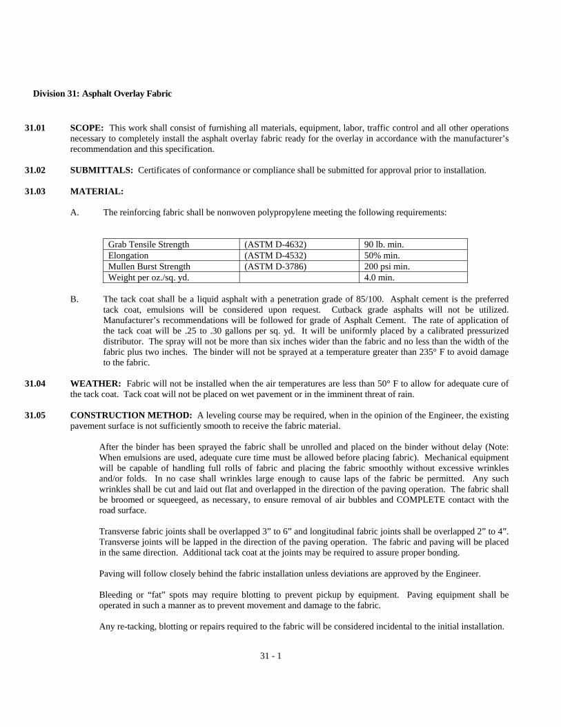
31 - 1
Division 31: Asphalt Overlay Fabric
31.01 SCOPE: This work shall consist of furnishing all materials, equipment, labor, traffic control and all other operations necessary to completely install the asphalt overlay fabric ready for the overlay in accordance with the manufacturer’s recommendation and this specification.
31.02 SUBMITTALS: Certificates of conformance or compliance shall be submitted for approval prior to installation.
31.03 MATERIAL:
A. The reinforcing fabric shall be nonwoven polypropylene meeting the following requirements:
Grab Tensile Strength (ASTM D-4632) 90 lb. min. Elongation (ASTM D-4532) 50% min. Mullen Burst Strength (ASTM D-3786) 200 psi min. Weight per oz./sq. yd. 4.0 min.
B. The tack coat shall be a liquid asphalt with a penetration grade of 85/100. Asphalt cement is the preferred
tack coat, emulsions will be considered upon request. Cutback grade asphalts will not be utilized. Manufacturer’s recommendations will be followed for grade of Asphalt Cement. The rate of application of the tack coat will be .25 to .30 gallons per sq. yd. It will be uniformly placed by a calibrated pressurized distributor. The spray will not be more than six inches wider than the fabric and no less than the width of the fabric plus two inches. The binder will not be sprayed at a temperature greater than 235° F to avoid damage to the fabric.
31.04 WEATHER: Fabric will not be installed when the air temperatures are less than 50° F to allow for adequate cure of
the tack coat. Tack coat will not be placed on wet pavement or in the imminent threat of rain. 31.05 CONSTRUCTION METHOD: A leveling course may be required, when in the opinion of the Engineer, the existing
pavement surface is not sufficiently smooth to receive the fabric material.
After the binder has been sprayed the fabric shall be unrolled and placed on the binder without delay (Note: When emulsions are used, adequate cure time must be allowed before placing fabric). Mechanical equipment will be capable of handling full rolls of fabric and placing the fabric smoothly without excessive wrinkles and/or folds. In no case shall wrinkles large enough to cause laps of the fabric be permitted. Any such wrinkles shall be cut and laid out flat and overlapped in the direction of the paving operation. The fabric shall be broomed or squeegeed, as necessary, to ensure removal of air bubbles and COMPLETE contact with the road surface. Transverse fabric joints shall be overlapped 3” to 6” and longitudinal fabric joints shall be overlapped 2” to 4”. Transverse joints will be lapped in the direction of the paving operation. The fabric and paving will be placed in the same direction. Additional tack coat at the joints may be required to assure proper bonding. Paving will follow closely behind the fabric installation unless deviations are approved by the Engineer. Bleeding or “fat” spots may require blotting to prevent pickup by equipment. Paving equipment shall be operated in such a manner as to prevent movement and damage to the fabric. Any re-tacking, blotting or repairs required to the fabric will be considered incidental to the initial installation.
31 - 2
Fabric placement by hand will only be allowed in areas where the mechanical equipment is restricted by size or configuration.
31.06 EXPERIENCE REQUIREMENT: The installation of the fabric must be performed by the manufacturer or by an installer who has proven substantial experience installing overlay fabrics during the last 3 years.
31.07 MEASUREMENT AND PAYMENT: The cost of all materials (to include tack coat and blotter materials), labor,
equipment, traffic control, as well as associated incidental expenses shall be included in the unit price for furnishing and placing the fabric.
The fabric will be measured by the square yard of surface area completed-in-place, and paid for as specified in the Unit Price Table.

32 - 1
Division 32: Project Identification Signboard
32.01 SCOPE: This work shall consist of all labor, materials, and equipment necessary to provide project identification signboards. The signboards shall be 4 feet high by 8 feet long constructed at conspicuous locations on the job site where directed by the Engineer.
32.02 MATERIALS AND EXECUTION: The field of the sign shall consist of one 4 foot by 8 foot sheet of grade B-B,
medium density overlaid exterior plywood not less than 5/8 inch thick. The completed signboard shall be secured to two 4 inch by 4 inch posts with 10 penny nails, 6 inches on centers. The completed signboard shall be mounted with the bottom 4 feet above grade. The posts shall be set plumb, 4 feet into the ground and tamped tight. The posts shall be set 5 feet, 5 inches center to center. All lumber shall be B or better Southern pine, pressure-preservative treated with pentachlorophenol. All nails shall be aluminum or galvanized steel. The entire signboard and supports shall be given one coat of exterior oil primer and two coats of exterior oil paint. The lettering and sign work shall be performed by a skilled sign painter using pain known in the trade as bulletin colors. The 1 inch by 1 inch border shall be painted black and the lettering shall be single stroke using bulleting blue. The lettering style shall be “Gothic”, “Roman Capitols”, or “Thick and Thin” styles.
32.03 MEASUREMENT AND PAYMENT: Project identification signboards will be measured and paid for per each sign
and as specified in the Unit Price Table.

Rev. 8/94 33 - 1
DIVISION 33 WATER MAINS / SERVICE LINES
33.01 SCOPE: The Contractor shall furnish all labor, material, equipment and supplies and shall perform all work necessary for the complete installation of the water main, water service lines and associated items, including all specified testing. The water main shall be constructed to the alignment shown on the approved construction plans, as well as size and type shown or specified. All materials for the water mains, service lines and associated items furnished by the Contractor shall be new and shall be as specified herein.
A. Pipe to be supplied with special locking or flexible type joints, or especially
fabricated sections will be specified or detailed on the plans. See other sections of these specifications as applicable.
B. Pipe stronger than that specified herein may be furnished at the Contractor’s
option and at no additional cost to the City, provided such pipe conforms in all other respects to the applicable provisions of these specifications.
C. The Manufacturer and Contractor shall use equipment and methods adequate to
protect pipe, joint elements, and coatings, from damage during hauling, storage and handling. When there is reasonable doubt as to the structural strength or water tightness of damaged sections, those sections will be rejected and replaced at the Contractor’s expense.
D. All Standards referenced shall be the latest edition.
E. Any proposed deviations from the listed materials must be approved by the
Engineer prior to ordering.
F. Valves on existing mains shall be operated only by authorized representatives of Public Utilities.
33.02 PIPELINE MATERIALS:
A. Ductile Iron Pipe shall be furnished in 18 or 20 foot laying lengths, with push-on type joints, except where mechanical joint or pipe is called for on the plans. Ductile iron pipe shall conform to the requirements of AWWA C151. Flanged ductile iron pipe shall comply with the requirements of AWWA C115.
1. Thickness Class of the pipe shall be Pressure Class 350 as required by the
pipe size, bedding type and depth. The pipe shall be round and gaged

Rev. 8/94 33 - 2
throughout its entire length. Ungaged pipe will not be accepted. 2. Lining – All pipe shall be single coat cement lined and sealed coated in
accordance with AWWA C104. 3. Joints shall be either mechanical, push on, or flanged conforming to
AWWA C111 (ANSI A21.11) or AWWA C115 (ANSI A21.15) as applicable.
All flanges and glands for pipes and fittings shall be made of ductile iron.
4. Fittings shall be manufactured in accordance with AWWA C110 (ANSI
A21.10) or AWWA C153 (ANSI A21.53), and shall be ductile iron. The minimum acceptable pressure rating shall be 350 psi. All fittings shall be lined in the same manner as ductile iron pipe.
5. Coating shall be provided on the exterior of all ductile iron pipe, joints and
fittings as required by AWWA C110, C111, C115, C151, or C153 as applicable. All pipes, joints and fittings shall be examined before and after laying to determine if the coating has been damaged. Any damaged areas and all joints shall be coated with approximately 1 mil of a bituminous coating, such as Koppers No. 50 or Intertol No. 49.
6. Polyethylene Wrap shall conform to the requirements of AWWA C105.
7. Retainer Glands shall be cast from high strength ductile iron. The gland
shall be compatible with mechanical joint connectors meeting the requirements of AWWA C111. Acceptable types shall be:
a. For PVC pipe, Uniflange Series 1300 or EBAA Iron Sales, Inc.,
Series 500 or 1500; b. Ductile Iron Pipe shall include a restraining mechanism which,
when actuated, imparts multiple wedging action against the pipe, increasing its resistance as the pressure increases. The gland shall be compatible with mechanical joints meeting the requirements of AWWA C111. Acceptable types shall be Mega-Lug Series 1100.
B. PVC Pipe shall be only used on pipelines smaller than 12 inches nominal
diameter. The outside dimension of the pipe shall be identical to that of ductile iron pipe. The pipe shall be provided in standard 20 feet lengths. Pipe shall conform to AWWA C900.

Rev. 8/94 33 - 3
1. Pressure Class of the pipe shall be 150 psi (DR 18). 2. Joints shall be push-on types. Solvent weld joints may not be used.
3. Fittings shall be identical to those provided for iron pipe. (Reference
Paragraph 33.02-A.4.)
4. Unless otherwise noted on the plans or directed by the Engineer, PVC pipe shall be used with a thrust block, and the Star Retainer – Series 1300 Restrainer as manufactured by the Uni-Flange Corporation, or approved equal.
5. Two-inch PVC pipeline shall conform to the requirements of AWWA
C901, formula PE 3406, Pressure Class 160. Joints shall be push-on type. C. Sleeves and Couplings:
1. Mechanical joint sleeves shall be solid type, long pattern, manufactured in accordance with ANSI/AWWA C110. Sleeves shall be of ductile iron with a minimum pressure rating of 350 psi. Glands shall be of ductile iron. Bolts and nuts shall be low-alloy steel or cast-iron except when otherwise specified. Glands, gaskets, bolts, and nuts shall be in accordance with AWWA C111 (ANSI A21.11). Generally, mechanical joint split sleeves shall not be used except as noted below.
Sleeves should not be machined in order to facilitate use with pipe of a class or type other than that for which the sleeve was intended. If machining is required, it must be approved by Public Utilities prior to use.
2. The use of bolted steel couplings shall be restricted to joining pipes of
different outside diameters, joining pipes of dissimilar materials, and joining section of steel pipe. Ferrous surfaces shall be coated with an epoxy coating. Enamel coatings are not acceptable. Bolted steel transition couplings shall be Rockwell 413, Dresser Style 162, or approved equal.
Bolted steel reducing couplings shall be Rockwell 415, Dresser Style 62,
or approved equal. Bolted steel couplings for joining pipes of the same outside diameter shall
be Rockwell 411, Dresser style 38, or approved equal. In those cases where the manufacturer lists two or more coupling lengths for a given type, the longer or longest listed length shall be used.

Rev. 8/94 33 - 4
D. Tapping Sleeves:
1. For All Pipelines - Tapping sleeves shall be split sleeve with mechanical joint-type end seals. Cast sleeves for tapping cast iron pipe, shall be of ductile iron meeting ASTM A536 Grade 65-42-12. Cast tapping sleeves for use on all pipes shall as manufactured by American Darling, Mueller Co., or approved equal.
2. Gaskets shall conform to applicable requirements of AWWA C111, and
shall be clearly marked to identify the diameter range for which intended. 3. Outlet Flange shall be 125 pound, drilling per ANSI B16.1, with standard
tapping flange counterbore per MSS SP-60. 4. Mechanical Joints, Bolts and Nuts shall conform with ANSI/AWWA
C111/A21.11. 5. Exterior Coatings shall be asphaltic varnish per Federal Specification TT-
V-51, Military Specification MIL C-450, or the manufacturer’s standard or optional coating as stated herein.
6. Valves shall be tapping flange mechanical joint bell unless shown
otherwise on the plans. With the exception of seat rings and body flange, all other features of the valve shall be in accordance with the requirements for double disc gate valves.
E. Valves:
1. General – All valves for buried service 4-inch and larger shall be provided with a 2-inch square operating nut.
All valves shall open right (clockwise). All valves shall be rated for a
minimum working pressure of 200 psi for valves 4 to 10-inch, 150 psi for valves 12-inch and larger, and shall be suitable for buried service.
Valve ends shall be flanged, mechanical joint or mechanical joint x flange
to suit pipe or fittings as shown on the plans and shall conform to the requirements of ductile iron pipe.
2. Double Disc Gate Valves shall be used for pipelines from 4 inches up to
and including 10 inches in diameter, and shall conform to AWWA C500. These valves may also be used on larger pipe if used in conjunction with a tapping sleeve.

Rev. 8/94 33 - 5
Gate valves shall be double disc type, iron body, non-rising bronze stem, with an O-ring stuffing box and shall be suitable for buried service.
Gate valves shall be Darling No. 55, Smith “Hydrogate”, Mueller A2380 or Kennedy.
3. Rubber-Seated Butterfly Valves shall be used on pipelines 12 inches and
larger in diameter, and shall conform to AWWA C504. Unless otherwise indicated, butterfly valves shall be short-body, Class 150B and suitable for buried service.
Manual operators shall be of the traveling nut or worm gear-type, sealed,
gasketed, and lubricated for underground service. The valve shall be operable with a minimum input of 150-foot pounds on
the operating nut, and capable to withstand an overload input torque of 450-foot pounds at full open and full closed positions without damage to the operator or valve.
The disc shall be capable of holding in any intermediate position without
creep or flutter. Valves shall be American Darling Class 150, Mueller “LineSeal III”,
Kennedy “ADAP-TORQ”, or M&H Valve. 4. Coatings – All interior ferrous surfaces of all butterfly valves shall be
coated in accordance with ANSI/AWWA C550 using a coating approved by the Virginia Department of Health for contact with potable water and shall not contain lead, coal tar resins, lamp black, carbon black or Bituminous materials.
The exterior surfaces shall receive two coats of a heavy coal tar coating or
an asphaltic varnish or the manufacturer’s standard exterior coating. 5. Brass Gate Valves (2”) – For use on meter assemblies, 2-inch mains, and
blow-offs shall be NIBCO Model T113-T or equal. Valve shall be of the non-rising stem, solid wedge, “T” handle type. Valve shall open left (counter-clockwise).
F. Fire Hydrants:
1. General – The hydrant base shall have a 6-inch mechanical joint bell, designed for connection to a horizontal 6-inch ductile iron pipe hydrant branch.
Rev. 8/94 33 - 6
a. The traffic coupling shall allow for 360-degree adjustment of the
upper standpipe. b. They hydrant shall be painted with Glidden Rustmaster, Metallic
Pure Aluminum Point (#Y-592). Paint is to be applied in accordance with the applicable sections of Division 41.
c. Operating nut shall turn clockwise to open hydrant. d. Extension spools shall be available from 6 inches to at least 48
inches, in 6-inch increments. Normal bury depth shall be 3.5 feet.
2. Hydrant Standards – Fire hydrants shall be of the dry barrel type and shall conform to AWWA C502.
a. Minimum flow rate shall be 1000 gallons per minute with not more
than 5 psi pressure drop through the steamer nozzle. b. Internal valve shall be 4½ inches in diameter and have bronze to
bronze seating. c. Nozzles: Two hose nozzles placed 180 degrees apart; 2½ inch
National (American) fire hose coupling screw threads. One steamer nozzle with 4½ inch National (American) fire hose coupling screw threads.
Fire hydrants shall be Mueller Centurion – A421, American Darling Mark-73, Kennedy Guardian K-81, or M&H Reliant Style 929, Metropolitan 4½”.
G. Valve Boxes: Valve boxes shall be City Standard VB-1, of Public Facilities
Manual, Volume II. Valve boxes and lids shall be manufactured from cast iron meeting ASTM A-48, Class 30. Casting shall be dipped in an asphaltic coating.
H. Air Vents: All air vents shall be tapped with a standard two-inch corporation tap.
All materials and construction shall be as shown in figure S-3, Air Vent Detail in the Public Facilities Manual, Volume II.
I. General: Steel pipelines are not standard and will only be installed where shown
on the plans.
Rev. 8/94 33 - 7
1. Steel Pipe for use in water pipelines shall be electrically butt-welded straight-seam, or seamless pipe. Steel pipe 6 inches and larger shall be in accordance with AWWA C200. Wall thickness, and exterior and interior coatings shall be as shown on the plans. Field welding of steel water pipe shall be in accordance with AWWA C206.
2. Interior Coating – The interior coating of all steel water lines shall be
coated with an epoxy coating system to a thickness of 14 to 24 mils. The coating must be approved by Virginia Department of Health for contact with potable water and shall not contain lead, coal tar resins, lampblack, carbon black or Bituminous materials.
J. Brass Pipe shall be red brass pipe meeting the requirements of ASTM B 43. Pipe sizes, wall thickness and dimensions shall meet the requirements of ASTM B 251 Table I for regular pipe. Brass pipe fittings shall be screwed end malleable iron pattern meeting the requirements of ANSI B16.15. They shall be finished rough, unless otherwise specified. Unions shall be of all brass or bronze with ground joints and shall be left semi-finished. Fittings shall be rated for steam working pressures finished. Fittings shall be rated for steam working pressures up to 125 psi. Joints shall be screwed type with threads clean cut, tapered and smooth, meeting the requirements of ANSI B2.1.
33.03 PIPELINE INSTALLATION
A. Reference Standards: The work shall be performed in accordance with the application sections of the following standards and regulations:
1. AWWA C600 2. AWWA C651 3. AWWA C105 4. AWWA C111, APPENDIX A 5. AWWA C115, APPENDIX A 6. AWWA C500, APPENDIX A 7. AWWA MANUAL M17 8. AWWA MANUAL M23 9. WATERWORKS REGULATIONS 10. PUBLIC FACILITIES MANUAL, VOLUMES 1 & 2
B. Required Submittals and Construction Records:
1. In all cases the Contractor shall submit the following for review and approval by the Engineer:
a. Material affidavit for all materials furnished. The affidavit shall

Rev. 8/94 33 - 8
include all of the following:
1) Name and location of work; 2) Name and address of Contractor; 3) Quantity and date or dates of shipment and/or delivery for
each item; 4) Manufacturer, Model No. and/or product description for
each item provided; 5) Signature of an officer of the manufacturing, fabricating or
supplying company, on a company standard form certifying that the listed materials were provided.
b. Construction records and specified data for installed valves and
fire hydrants. The dimensions and data may be clearly indicated on prints of the Contract Drawings or separate sketches as appropriate.
1) Locations of horizontal bends, vertical offsets, valves, ends
of installed lines, and corporations with dimensions referenced to existing mains, property lines, curb lines, or other permanent objects.
2) Data for valves installed – date set, cover, size,
manufacturer, number of turns to open, direction of opening, and joint types.
3) Data for hydrants installed – date set, manufacturer, depth
of bury, distances main to valve, and valve to hydrant. 4) Any sheeting left in place.
c. Flushing sequence to be used prior to disinfection.
2. In those cases where the installation or procedure proposed is not detailed
on the plans or in the specifications; or a significant modification is required, the Contractor shall submit the following for review and approval by the Engineer:
a. Procedures and equipment to be used for pressure testing, leakage

Rev. 8/94 33 - 9
testing, and disinfection. b. Detailed drawings and method of joint or pipe restraint. c. Method of installing polyethylene tube or sheet material for pipe
encasement. d. Detailed drawings of proposed modifications, off-sets or special
fittings and method of installation. C. Line and Grade: All pipes shall be laid to line and grade as shown on the plans
and as specified herein. Normally, the grade at the top of the proposed pipeline is determined by surface grade and cover requirements.
1. Careful attention shall be given to the depth of new pipelines at points
where tie-ins to existing mains are to be made. The existing main shall be uncovered in the presence of the Inspector and the new pipeline set to proper elevation to provide for a perpendicular and level tie-in. Obstructions within the tie-in length may require special offsets by the Contractor.
2. The Contractor shall investigate the proposed location of the main far
enough in advance of the work to determine where conflicts will occur and to determine joint deflections necessary to clear any obstructions.
Normal cover (top of pipe to ground or pavement surface) for water mains shall be 36 inches. If an obstruction is encountered the Contractor may install the pipe with cover of from 24 inches minimum to 48 inches maximum. Where obstructions indicate that either the minimum or maximum cover will be continuous for a horizontal distance of greater than 162 feet (9 pipe lengths), the Department of Public Utilities shall be notified before installation begins, at which time the situation will be assessed for possible modifications. All changes will necessitate plan revision with must be approved prior to installation.
3. PVC Pipe (C900) shall not be utilized if the depth of cover will be less
than 30 inches.

Rev. 8/94 33 - 10
D. Separation of Water Pipelines and Sanitary Sewers and Laterals:
1. General – Virginia Health Department Regulations require that water mains be installed with 10 feet minimum horizontal separation and 18 inches minimum vertical separation. In areas where sanitary sewerage facilities exist prior to a water main installation, the Contractor shall install the water pipeline and/or replace portions of the sanitary sewer mains and laterals in compliance with the provisions of this section.
2. Parallel Separation – Except as shown on the plans, or otherwise directed
by the Engineer, water lines shall be laid at least 10 feet horizontally from existing or proposed sanitary sewer lines. This distance shall be measured edge to edge. Should local conditions prevent a lateral separation of 10 feet, a water line may be laid closer than 10 feet to a sewer lateral or sewer line if the top of the sewer pipe is at least 18 inches below the bottom of the water line. Where this vertical separation cannot be attained, the sewer line shall be constructed of “water quality” pipe and pressure tested at 50 psig for 30 minutes to assure water tightness prior to backfilling.
3. Vertical Separation – Water lines crossing sanitary sewer lines or laterals
shall be laid to provide a separation of at least 18 inches between the bottom of the water line and the top of the sewer line.
Where this separation cannot be attained (such as compliance with 24
inches minimum cover on the water line) the sewer line shall be constructed of water quality pipe, or in the case of existing sewer lines, the existing sewer shall be replaced with “water quality” pipe for a distance of 10 feet on each side of the crossing. Also a full (18-foot minimum) length of water main shall be centered on the crossing so that the joints will be as far as possible from the sewer.
Water mains shall not pass through nor come in contact with any part of a
sanitary sewer, combined sewer, or sewer manhole. 4. Sewer Line Replacement – In those cases where the water line must cross
above a sanitary sewer or house lateral, and the bottom of the water line is less than 18 inches from the top of the sewer, the Contractor shall remove a suitable length of the sewer line and replace it with ductile iron or PVC-C900 water quality pipe of the same nominal diameter as the sewer line.
The pipe shall be joined using suitable transition couplings of rubber or neoprene material and stainless steel circumferential clamps.

Rev. 8/94 33 - 11
In those cases where the water line must pass beneath an existing sewer the water line shall be installed with a minimum distance of 18 inches from the top of the water line to the bottom of the sewer; and, in addition, a suitable section of the sewer shall be replaced with water quality pipe as described above.
E. Material Handling:
1. The pipe and fittings shall be handled and protected during loading, transporting and unloading operations in such a manner as to avoid damage. Pipe and fittings shall be unloaded by lifting with hoists or skidding so as to avoid shock, damage, or contamination. Under no circumstances shall the pipe or fittings be dropped nor shall they be permitted to roll against pipe already on the ground.
Insofar as practical, each piece of pipe shall be delivered and unloaded near the place where it is to be installed and where it will not interfere with excavation, traffic, or adjacent property owners. All damage pipe and fittings will be rejected and such rejected pipe and fittings shall be removed from the site as directed by the Engineer. In the event of slight damage to be repaired on the site. Such repairs shall be made at the Contractor’s expense.
2. Cleaning and Inspection of Pipes and Castings – The inside of pipes and
castings shall be thoroughly cleaned before laying and shall be kept clean until accepted in the completed work. Whenever the work is interrupted, all open ends of pipe shall be temporarily blocked with plugs. All pipes and special castings shall be carefully examined for defects, defective pipes and castings shall not be installed. If any such pipe or casting is discovered after placement, it shall be removed and replaced with an acceptable pipe or casting by the Contractor at his own expense.
F. Earthwork:
1. Trench Excavation – Excavation shall conform to the lines and grades shown on the plans and established by the Contractor. No trench shall be opened more than one hundred (100) feet in advance of the completed pipe work without the written permission of the Engineer. The lines of excavation of trenches shall be made so there will be a clearance of at least eight (8) inches on each side of the barrel of pipe to the grades shown on the profile and established by the Contractor. Excavation shall not be carried below the established grades and any excavation below the required level shall be backfilled, and tamped at the Contractor’s expense.
Rev. 8/94 33 - 12
The bottom of pipe trenches shall be accurately cradled and shaped to fit the barrel of the pipe for a depth of 0.1 times the outside diameter of the pipe to such that the full length of the barrel of the pipe will rest uniformly in the trench bottom, with bell holes excavated accurately by hand.
The Contractor shall do all sheeting, bracing, and shoring necessary to perform the work and protect workers and excavations as required to conform to all governing laws and ordinances and as directed by the Engineer. The Contractor shall erect, maintain and safeguard temporary bridges, walkways, or crossings where it is necessary to maintain traffic. Where trenches are open in the vicinity of pedestrian or vehicular travel lanes, suitable barriers will be constructed and maintained and the work will be further protected from sunset to sunrise with a sufficient number of lights or flares to fully protect the public from accidents or account of construction of pipe lines or appurtenances. All necessary dewatering and pumping shall be performed in such a manner as to keep the trench in a satisfactory condition for pipe laying. The Contractor shall conduct his operations such as to provide adequate drainage of the construction area and adjacent areas affected by construction through temporary ditching, piping or other means as may be appropriate. Drainage shall not be impeded by construction operations.
2. Backfilling shall be done with material free from large clods and foreign
matter, and shall evenly and carefully be placed around and over the pipe in six (6) inch maximum layers, each layer being thoroughly and carefully tamped until twelve (12) inches of cover exists over the pipe. The remainder of the backfilling may be placed in twelve-inch (12”) horizontal layers.
Tamping shall be performed on each layer using suitable compactors.
Compaction equipment specifically designed for these purposes must be present and operational at the job site and shall be utilized throughout the length and depth of the trench to obtain uniform compaction. It shall be the Contractor’s responsibility to provide compaction of the backfill material to 95% of its maximum density as determined in accordance with VTM-1 (VDOT) at the optimum moisture content within plus or minus 20% of its optimum moisture. Surplus materials shall be disposed of by the Contractor. Pavement and shoulders are to be cleaned of excess material immediately after backfill.
3. Compaction Tests – The City, or its authorized representatives, reserve the
right to perform compaction tests on any or all portion(s) of backfill

Rev. 8/94 33 - 13
placed in the trench at no costs to the Contractor. However, in the event the compaction of this backfill is not in compliance with the Specifications then the Contractor shall take corrective measures at no costs to the City to bring the backfill within the limits of the Specifications. The Contractor shall then be responsible for reimbursing the City all costs associated with the performance of compaction test(s) in those sections of the backfill that failed the compaction test(s). However, if the test(s) should indicate compaction within the required limits, the City will then be responsible for cost.
G. Sheeting Left in Place:
1. Should it be determined that removal of sheeting in excavated areas might endanger adjacent properties or structures, the Engineer may direct that the sheeting be left in place. In such instances, sheeting will be cut off one (1) foot below grade and left in place. Backfilling will be performed in accordance with appropriate sections of this specification.
2. Payment for sheeting left in place at the direction of the Engineer shall be
made in an amount equal to the cost of materials, as evidenced by the Contractor’s invoices, plus fifteen (15%) percent.
H. Sub-Surface Utility Warning Tape: All non-ferrous water mains shall be
identified by a sub-surface utility warning tape placed at an elevation not less than six (6) inches, nor more than twelve (12) inches below the proposed finished grade. The utility warning tape shall be manufactured by Griffolyn Co., or approved equal. The tape shall be of a durable, metalized, plastic film similar to Terra Tape D for identification of water mains; bright blue tape imprinted with the legend “Caution – Waterline Below” shall be used.
I. Field Cutting Pipe: Pipe may be cut using methods approved by the pipe
manufacturer. Cuts shall be made at 90 degrees with the centerline of the pipe so that a framing square placed against the side of the pipe will reveal not more than ¼ inch variation across the diameter of the pipe in any direction. Cut ends and rough edges shall be ground smooth and for push-on type connections, the cut end shall be beveled slightly on the outer edge.
Pipe coatings damage din handling or during the cutting operation shall be
touched up and repaired prior to installation. J. Joint Assembly: Gaskets and joint assembly shall be in accordance with AWWA
C111 or the manufacturer’s recommended procedures, if more stringent.

Rev. 8/94 33 - 14
Both the gasket and plain end of the pipe shall be thoroughly cleaned to remove all loose rust and foreign material. Just prior to assembly, both the gasket and the plain end shall be brushed with soapy water or approved pipe lubricant.
1. Joint Deflection at any single joint shall not exceed 80 percent of the
manufacturer’s allowable deflection for the type of joint to be used. When joint deflections are required the pipe shall be inserted straight into
the bell and the pipe deflected after complete insertion. 2. Mechanical Joint – T bolts (or tie bolts) shall be alternately and uniformly
tightened to insure that the gland compresses the gasket evenly around its perimeter.
Nuts shall be gradually tightened to the torque ranges as follows:
Pipe Size Bolt Diameter Range of Torque
(ft. lb.) 4” – 24” ¾” 75 – 90 30” – 36” 1” 100 – 120 42” – 48” 1¼” 120 – 150
Bolts of stainless steel or other corrosion control steel alloys shall be used when specifically called for on the plans or stated herein.
K. Joint Restraint:
1. Concrete Buttresses and concrete anchors shall be placed where indicated on the plans or as required herein. Concrete buttress and anchors shall be carefully formed as required to prevent the joint gland or fasteners from being embedded in concrete and therefore accessible for future repairs. Alternate forming requirements must be approved by the Engineer prior to installation.
Concrete shall be ready-mixed concrete conforming to ASTM
Specification C-94. All concrete shall be Class A-3 and shall develop a compressive strength of 3000 psi at twenty-eight (28) days. The slump range for the concrete shall be three (3) inches to four (4) inches. Concrete admixtures as per Division 36 of these Specifications may be used to provide workability.
Rev. 8/94 33 - 15
Concrete shall be conveyed from the mixer to the place of final deposit by methods which will prevent separation or loss of materials. Adequate equipment shall be provided for heating the concrete materials and protecting the concrete during freezing or near freezing weather as per Division 36.
2. Restraining Rods shall be installed as shown on the plans or as directed by
the Engineer. Tie-bolts, threaded rods, couplings, nuts, washers and clamps used for rodding shall be manufactured expressly for use in restraining underground pipelines and shall be installed as recommended.
ALL RODS AND FASTENERS SHALL BE COATED WITH TWO
COATS OF BITUMINOUS PAINT BEFORE BACK-FILLING THE TRENCH. As a minimum, the rods shall have a minimum yield strength of 36,000 psi.
3. Retainer Glands shall be installed where indicated on the plans or as
directed by the Engineer, either as the primary method of restraint or as a supplement to concrete blocking, or other methods.
Retainer glands shall be carefully installed to properly compress the
gasket. Peripheral set bolts shall then be tightened gradually to the manufacturer’s recommended torque, and in a manner that the circumferential alignment of the joint will not be altered.
4. Temporary Blocking may be of heavy timber, steel, or other materials and
shall be of sufficient strength and securely braced or supported so as to prevent any movement of the pipe or fittings. Poured in place concrete shall not be used.
The Contractor shall be solely responsible for the adequate restraint of
pipe and fittings during pressure testing or during any other procedure requiring that the pipeline be pressurized prior to final acceptance by the City.
L. Installing Valves: Valves shall be installed at the locations shown on the plans or
as otherwise directed by the Engineer.
Valves will be set with the operating stem truly plumb. The top of the operating nut shall be not more than 4 feet below the top rim of the valve box when said box is properly installed to finished grade. Valve stem extension devices shall not be used. Valves shall be supported by a gravel bed and shall not be supported by the pipeline.

Rev. 8/94 33 - 16
M. Installing Fire Hydrants: Hydrants shall be installed at the locations shown on the
plans or as otherwise directed by the Engineer.
Hydrants shall be set with their vertical axis truly plumb, and in accordance with Standard Drawings in Public Facilities Manual, Volume II, as applicable. The hydrant branch valve shall be set in accordance with Paragraph L above. Generally, in those cases where a parallel ditch exists between the pavement or shoulder and the proposed hydrant, and the depth of that ditch is greater than 18 inches (edge of shoulder to flow line of ditch), a pipe culvert, or an extension of an existing culvert, will be required. When shown on the plans, the culvert pipe of the type, diameter and length indicated, shall be installed. For payment purposes the culvert installation and backfill will be considered a part of the complete hydrant installation. Special close-coupled or offset hydrant branch installations will be detailed on the plans. In the event that an obstruction is discovered during excavation, which requires that the standard or detailed hydrant branch be modified, the Contractor shall submit a workable design for approval by the Engineer. Newly installed fire hydrants not yet in service shall be covered with a bag or sheet material, securely tied in place; indicating to fire fighters that hydrant is not usable. Cover shall be removed as the line is activated.
N. Appurtenances:
1. Blow-off: All dead-end lines shall be equipped with a permanent blow-off. A two-inch blow-off shall be provided on all lines and shall be installed as shown on Figure BOV-1, of Public Facilities Manual, Volume II.
2. Air relief assemblies required on the plans or installed by the Contractor,
with the approval of the Inspector, to facilitate air removal shall be installed in accordance with Standard Drawing S-3.
O. Polyethylene Encasement: Encasement of the pipeline shall be installed as shown
on the plans or as directed. In the event that corrosive soils (as defined by Appendix “A” of the ANSI/AWWA C105/A21.5) are encountered during excavation, the Engineer may direct that all, or a portion, of the pipeline be encased, whether or not encasement was indicated on the plans.
P. Pressure Tests: All newly laid pipe shall be subjected to a hydrostatic pressure of

Rev. 8/94 33 - 17
1.5 times the expected working pressure, or 125 psig, whichever is greater, measured from the high point in the line. Tests for leakage shall be conducted concurrently with the pressure test. Pressure tests shall be of at least a two (2) hour duration, shall be in accordance with AWWA C600, except as modified herein; and must be witnessed by authorized personnel of the City.
1. Gauges and Equipment – The Contractor shall furnish all pumps, fittings
and gauges as necessary to fill the line with potable water, dispel air from the system, and pressurize the pipeline for the tests. The Engineer reserves the right to test gauges on a dead weight tester to determine their accuracy. The Contractor shall provide and install an approved backflow preventer in the water supply line, between the newly laid pipeline and the existing distribution system.
2. Water for pressure tests will be charged to the Contractor. The charge will
be calculated using current rates for water consumption. 3. Pressure tests shall not be conducted against closed valves other than
blow-off valves and hydrant foot valves. 4. Evaluation of Pressure and Leakage Tests – After the specified pressure is
attained and stabilized, any pressure drop during the duration of the test will be considered as test failure.
If the pressure is higher than required at the start of the test, it will be the
base pressure for determining compliance. Any leakage, either visually evident, or evident due to pressure drop
during the test, shall be considered test failure. The Contractor shall repair and correct any and all leaks in order to achieve a successful pressure test.
Q. Disinfection of Water Mains:
1. Flushing – All mains shall be thoroughly flushed with a full pipe diameter discharge, using potable water prior to the introduction of disinfecting agents. Velocity in the main during flushing shall attain a velocity of 2.5 feet per second for a period sufficient to remove sediment and discolored water from the main. All valves and hydrants shall be operated and flushed.
Rev. 8/94 33 - 18
Flushing shall progress in a logic sequence (approved by the Engineer) from the source of water to the end of the installation, without flushing dirty water through portions that have already been flushed. Water for the initial flushing and flushing after chlorination will be furnished by the Owner, with charges rendered as noted above. It is the Contractor’s responsibility to provide adequate drainage for the discharge without causing a public nuisance.
2. Chlorination of the main and appurtenances, and favorable bacteriological
analysis received from samples collected therefrom, shall be completed before any newly laid pipeline is connected to the potable water distribution system.
All work shall be in accordance with AWWA C651, and as specified
herein. The Contractor shall provide all equipment and materials for disinfection and testing for chlorine residual. Chlorine residual testing shall be done by either the DPD or Amperometric Titration methods.
3. Chlorination shall be by the continuous feed method. Potable water shall be introduced into the pipeline at a constant flow rate.
An approved double-gate – double-check valve backflow preventer shall be installed in the source line to protect the existing distribution system. Chlorine shall be added at a constant rate (using equipment specifically designed for the purpose), proportional to the water flow, so that the free chlorine concentration in the water main is at least 25 mg/1. Additional chlorine may be required depending on-site specific conditions.
The chlorinated water shall remain in the pipeline for at least 24 hours,
after which time the residual chlorine content shall be at least 10 mg/1. All valves and appurtenances shall be operated while the heavily chlorinated water remains in the pipeline.
4. After the required retention time the heavily chlorinated water shall be
flushed from the main, using potable water. However, the highly chlorinated water shall not be flushed out until the residual is less than 20 mg/1.
Disposal of the heavily chlorinated water is the responsibility of the
Contractor and shall be in such a manner as to cause no adverse environmental effects such as fish kills or erosion and in compliance with all federal, state and local requirements.
5. The Contractor shall provide sampling taps as specified in Section 7.3 of
Rev. 8/94 33 - 19
AWWA Specification C-651. A minimum of two (2) sampling taps shall be located as directed for any pipe being sterilized less than 1000 feet. For pipe installation greater than 1000 feet the Contractor shall provide one (10 tap for each 1000 feet of, or fraction thereof, plus one (1) tap. In the event the line branches, at least one (1) tap will be made on each branch line.
The standpipes with wheel valves or cut-offs attached to the water mains to facilitate testing shall not be exposed above ground at any time except while collecting samples. They should be enclosed in a box below ground. After completion of the tests, the wheel valve and the standpipe shall be removed. The standpipe shall be removed by cutting off at the corporation tap.
6. A minimum of two samples taken 24 hours apart shall be collected from
each section of pipeline and delivered to the Department of Public Utilities, City of Chesapeake, for testing purposes. All samples must successfully pass bacteriological testing prior to placing the pipeline in service. If additional testing is required, the Contractor is responsible for the water main and testing at no cost to the City until the samples pass the above requirements.
Chlorine residual measurements shall be taken and recorded at the time
each sample is collected. 7. If the line is not activated within three weeks of the date of the final
sample passed, the line shall be resampled in accordance with Paragraphs 5 and 6 above. If any sample fails, the entire pipeline shall be re-disinfected in accordance with this Section.
R. Tie-Ins to Existing Mains:
1. General:
a. All materials shall be installed in accordance with the manufacturer’s recommendations including, but not limited to, alignment, torque requirements, tolerances, etc.
b. All materials shall be thoroughly disinfected before they are
installed. c. No tie-in shall be made except in the presence of the Inspector.
Rev. 8/94 33 - 20
d. Final tie-in shall not be made until the bacteriological samples collected following disinfection of the new main have indicated no contamination.
e. Disinfection shall be performed in accordance with Sections 9 and
10 of AWWA C-651 as applicable.
2. Tapping Existing Mains Under Pressure:
a. General; Tapping sleeves and valves shall be utilized for connecting to existing mains when shown on the plans, or when in the opinion of the Engineer, the use of other methods would require interruption of water service to an extent considered undesirable.
b. Sleeve to Joint Distance: The center line of a tapping sleeve and valve assembly shall be located a minimum distance from an existing pipe joint as follows:
Size of Tapping Sleeve Min. Distance Centerline Of Sleeve to “Home Line”
Of Existing Joint
4”, 6” & 8” 3 feet 10”, 12” & 16” 5 feet
In cases where the horizontal alignment as shown on the plan would result in a “sleeve to joint” distance less than the minimum stated above, the Engineer may direct the substitution of a MJ x MJ x FL tee connection, using suitable sleeves and nipples.
When, in the opinion of the Engineer, offsets or modifications to new pipeline alignment are required, sub-surface investigations, submittals for modifications, etc., shall be in accordance with the other requirements of this Division.
c. Outside Diameter of Existing Mains: It shall be the Contractor’s responsibility to determine the outside diameter at the location of the proposed tap in order that the tapping sleeve or couplings to be provided can be properly installed.
d. Pressure Testing: In addition to pressure testing of newly installed
pipelines, each tapping sleeve and valve assembly shall be tested

Rev. 8/94 33 - 21
prior to making the tap. Water shall be injected into the body of the sleeve, to a pressure of 125 psig, through the test plugs. If test plugs are not provided in the sleeve, a tapped mechanical joint plug shall be assembled to the valve for testing purposes. Pressure shall be maintained for a one-hour period without evidence of leakage. This test must be witnessed by authorized personnel of the City. A satisfactory test shall be completed before beginning the tapping (cutting) operation.
e. Restraint: All installed tapping sleeves shall be restrained by
concrete buttresses. Concrete dimensions for a tapping sleeve and valve shall be as tabulated for a tee fitting with like nominal diameters of run and branch. Fasteners and glands shall be coated with a bituminous coating or shielded with polyethylene film to prevent a bond between the concrete and the sleeve components.
f. Tapping: Upon completion of the tap the Contractor shall save the
coupon to show the Inspector.
3. Sleeve-In of Straight Pipes:
a. Sleeve-in connections shall be used whenever possible to reduce head loss in the system.
b. Materials used for the sleeve shall conform to the requirements of
this Division of this Specification.
4. Upon completion of the tie-in, it shall be flushed to remove the highly chlorinated water. One sample for bacteriological examination shall be collected from the point of discharge of the flushing water. The requirements of Division 33.03-Q shall apply except as modified above.
S. Shut-Down for Main Adjustment or Tie-Ins: Main adjustment work shall be permitted only between eleven (11) p.m. and five
(5) a.m. from Tuesday through Thursday. Contractor must coordinate this work with the Departments of Public Works, Public Utilities and Fire Department, and provide forty-eight (48) hours notice prior to doing any such work. Contractor must notify the affected customers at least twenty-four (24) hours before the shutdown of the water system. All fittings and pipe work necessary to complete the adjustment must be assembled and finished above ground prior to the shutdown of the water system, unless otherwise approved by Public Utilities.
Rev. 8/94 33 - 22
T. Abandonment of Existing Pipe in Place: In the event that an existing pipe is abandoned as the result of the installation of
new pipe, the ends of the abandoned pipe shall be capped or plugged. All valve boxes shall be removed from the abandoned line and the valves buried with the nuts removed. All hydrants shall be removed from the abandoned line.
U. Material Salvage:
The disposal of all materials abandoned as a result of this work is the Contractor’s responsibility; however, the Department of Public Utilities retains salvage rights to the following items: water meters, meter boxes and lids, valve boxes and lids, fire hydrants and valve boxes. These items shall be delivered, at the Contractor’s expense, to:
Department of Public Utilities Water and Wastewater division 906 Executive Boulevard Chesapeake, VA 23320
33.04 WATER SERVICE LINES:
A. Domestic Water Meters 5/8” to 2” Size: These meters are classified as small meters.
1. Water Meters:
a. Type: Magnetic drive, sealed registers, straight reading
conforming to AWWA Standard C-700 (latest revision). Meter may be nutating or oscillating type piston or disc. All meters will be frost proof type. Meters will be of standard laying length according to their sizes.
b. Cases: All meters will have a non-corrosive bronze outer case.
Register boxes shall be all bronze with lid being plastic or bronze. Cast iron or plastic frost bottom plates shall be used. Bottom plates must be four-bolt type and must be protected against corrosion by inner liner. One and one-half to two (1½” – 2”) inch meters shall be split-type case with bronze lower and upper shell assemblies.
c. Registers: The register must be a hermetically sealed and tamper
proof unit. The register shall be straight reading in cubic feet with

Rev. 8/94 33 - 23
test sweep hand. Numeral wheels for units and tens registration to be of different color from other numeral wheels. The register shall be guaranteed against defects and materials and workmanship for twenty-five (25) years from date of shipment.
d. External Bolts and Washers: All external bolts and washers shall
be of corrosive resistant material and be easy to remove from the main case.
e. Measuring Chambers: The measuring chambers shall be of bronze
or a suitable synthetic polymer and shall not be cast as part of the main case.
f. Serial Numbers: Serial numbers of meters must be imprinted on
the case, as well as register box lid. g. Companion Flanges: All 1½ and 2 inch meters shall be oval
flanged and supplied with companion flanges, gaskets and bolts, unless stated otherwise in purchase request.
h. Test: Meters must be tested for accuracy of registration in
accordance with AWWA C-700 (latest revision) Standards for testing cold water meters. These certificates shall be sent to:
Water and Wastewater Administrator Department of Public Utilities P.O. Box 15225 Chesapeake, VA 23328
i. Guarantee and Maintenance Program: Quotations will be accepted
only from those companies who are actively engaged in manufacture of all parts for their meters in the United States and who have a minimum of three (3) years of satisfactory experience with their meters. The meters shall be guaranteed to meet AWWA New Meter Accuracy Standards for a period of one (1) year after the date of shipment.
The Manufacturer must provide a meter maintenance plan in
writing, which includes the price of repairing meters to meet AWWA New Meter Accuracy Standards after the expiration of the performance guarantee.
The Manufacturer must submit a program to guarantee meter
Rev. 8/94 33 - 24
performance for fifteen (15) years or 1,000,000 gallons for 5/8-inch meters; 1,500,000 for ¾-inch meters; 2,000,000 gallons for 1-inch meters; and 100,000,000 gallons for 1½-inch and 2-inch meters, whichever event occurs first.
2. Service Line Sizes:
Service lines shall be sized in accordance with City and State Standards to provide adequate water flow and pressure to the property being served. Minimum service line shall be ¾ inch. For the water meter sizes presently acceptable, the service line sizes shall be as follows:
Water Meter Size Service Line Size
5/8 inch x 5/8 inch and 5/8 inch x ¾ inch
¾ inch
¾ inch x ¾ inch 1 inch 1 inch 1½ inch 1½ inch 2 inch 2 inch 2 inch
(>15 feet long 3 inch
(16-50 feet long)
For service lines more than 50 feet long the service line size shall be the next larger standard size.
3. Materials:
a. Pipe: Appropriate O.D. copper shall be used for service lines.
Copper tubing shall conform to ASTM A88, Type “K”. b. Corporation Stops: The corporation stops shall conform to the
O.D. for copper tubing of the required size service line. Inlet threads shall be AWWA standard inlet threads and conform to AWWA C-800 for high-pressure service. The following Ford pack joint or Mueller compression type fittings to match service line O.D. shall be used.
1) Ford pack joint No. F-1000 for service lines ¾ inch to 2
inch.

Rev. 8/94 33 - 25
2) Mueller compression fitting No. H-15008 for service lines
¾ inch to 1 inch; and No. H-15013 for service lines 1½ inch to 2 inch.
c. Angle Curb Stops shall conform to AWWA C-800 for high-
pressure service. The following types shall be used:
1) 5/8” x ¾” x ¾” Ford pack joint No. KV43-332 with ¾” inlet and coupling nut for ¾” meter; or Mueller compression fitting No. H-14253 with ¾” inlet and coupling for ¾” meter.
2) 5/8” x ¾” x 1” Ford pack joint No. KV43-342 with 1” inlet
and coupling for ¾” meter; or Mueller compression fitting No. H-14253 with 1” inlet and coupling for ¾” meter.
d. Angle Flanged Valves shall conform to AWWA C-800 for high-
pressure service. The following types shall be used:
1) 1½” x 1½” x 1½” Ford No. FV43-66w with pack joint inlet; or Mueller compression No. H-14277 with compression inlet to match O.D. of 1½” tubing.
2) 2” x 2” x 1½” and 2” Ford No. FV43-777w with pack joint
inlet; or Mueller No. H-14277 with compression inlet to match O.D. of 2” tubing.
e. Meter Boxes and Vaults:
1) For meter sizes 5/8” to 1” meter boxes shall be Rome Type
MBX1. 2) For meter sizes 1 ½” and 2” meter vaults shall be 18” x 18”
x 36” fabricated with ¼” diamond plate steel in accordance with the typical detail shown in Public Facilities Manual, Volume II.
f. Double strap service saddles must be used for all PVC mains and
on ductile iron mains less than eight (8) inches in diameter for taps 1½” or 2”.
g. Additional materials for 1½” and 2” meters:

Rev. 8/94 33 - 26
1) Required size swing check valve shall conform to AWWA
C-508 and shall be Nibco No. T-413-Y, or approved equal. 2) Required size gate valve shall be bronze T-handle type
Nibco No. T-113-T, or approved equal. Wheel valves will not be accepted.
3) 2” brass adapters shall be MIP Ford pack joint No. C84-77
or MIP Mueller compression No. H-15429 to match O.D. of the pipe.
h. For condominiums, townhouses and duplexes (5/8” x ¾” meter
with a ¾” service line), where feasible a 1” line may be installed and split at the curb, using a ¾” x 1” Y-branch Ford No. Y44-243, ¾” x 1”, or Mueller No. H-15343 ¾” x 1” O.D. tubing.
i. Service Saddles shall conform to AWWA C-800 for high pressure
service:
1) Ductile iron or PVC shall be equal to the Rockwell 313 Double Strop Saddle. Where corrosion protection is necessary, Style 317 (nylon coated) shall be used.
2) Asbestos Cement shall be equal to the Rockwell 331
Saddle.
4. Installation (meter size ⅝” to 2”):
a. The installation of meters shall be in accordance with the detail shown in Public Facilities Manual, Volume II.
b. Meter boxes or vaults shall be placed at the end of each service
line with their tops set at finished grade. For 1½” to 2” meters, all valves and the meter shall be placed inside of the vault.
c. Service lines shall have a minimum of 24” to a maximum of 30”
cover from the top of the tubing to finished grade. The top of the angle curb stop/valve shall be set at an elevation 12” below finished grade.
B. Domestic Meters 3” Size and Larger and Detector Checks: These meters are
classified as large meters. Meters and detector checks shall be delivered to Public

Rev. 8/94 33 - 27
Utilities, 906 Executive Drive, for checking and installation by City forces.
1. Water Meters 3” and larger:
a. Compound, combination or turbine meters manufactured by Hersey or Rockwell shall be used. Contact Public Utilities for a list of specific models approved.
b. Meters must read in cubic feet. c. Compound meters with single registers measuring all flows,
manufactured by Hersey or Rockwell are acceptable.
2. Meter and Service Line Size: Water meter shall be sized in accordance with City and State Standards to provide adequate water flow and pressure to the property to be served. The size of the service feed line shall be one pipe size larger than the meter size. The meter shall be capable of handling the peak domestic flow without exceeding the rated capacity of the meter.
3. Materials: All piping, valves and fittings shall conform to City water
main Standards. 4. Installation:
a. Installation of large meters shall be in accordance with the details shown in Public Facilities Manual, Volume II.
b. Meter vaults shall be metal or concrete as shown on the plans and
shall conform to the details shown in Public Facilities Manual, Volume II.
c. Large meters (3” and above) shall have a bypass of same size as
the meter (except 3” where the bypass shall be 4”). d. All fittings and valves shall be rodded and retained. e. All connections at the water main shall be valved either by a
tapping sleeve and valve or a gate valve in accordance with the City water main standards.
f. No solvent joints shall be used. g. All fittings shall have a minimum of 30” and a maximum of 48”

Rev. 8/94 33 - 28
cover from the finished grade and the top of the vault.
h. The Contractor shall notify Public Utilities (382-3411) at least 48 hours prior to the start of large water meter vault installation.
i. Testing of service pipe and bypass shall be performed in
accordance with Paragraphs 33.03 – P and Q.
C. Closed Fire Service with Detector Check Meters:
1. Water Meters:
a. Detector check meter vault manufactured by Hersey, Mueller, or Viking shall be used.
b. By-pass meter on the detector check shall be of the appropriate size City standard meter and shall be located at the same elevation as the top of the detector check meter.
2. Meter and Service Line Size: The detector check shall be sized in
accordance with City and State Standards to provide adequate flow and pressure to the property to be served. The size of the service feed line shall be one pipe size larger than the meter size.
3. Materials:
a. All piping, valves and fittings shall conform to City Water Main
Standards. b. All fittings for the detector check by-pass meter shall be ¾” brass
and ¾” gate valve and ¾” check valve as shown in the typical detail in Public Facilities Manual, Volume II.
4. Installation:
a. Installation of detector check meter vault shall be in accordance
with the details shown in the Public Facilities Manual, Volume II. b. Meter vaults shall be metal or concrete and shall conform to the
details shown in the Public Facilities Manual, Volume II. c. All connections at the water main shall be valved either by tapping
sleeve and valve or a gate valve in accordance with City Water Main Standards.
Rev. 8/94 33 - 29
d. No solvent joints shall be used. e. All fittings shall have a minimum of 30” and a maximum of 48”
cover from the finished grade and the top of the vault. f. The Contractor shall notify Public Utilities (382-3411) as least 48
hours prior to the start of the meter installation. D. Combination Fire and Domestic Water Meters:
1. Water Meters: MFM-MCT meters measuring in cubic feet manufactured by Hersey or approved equal shall be used.
2. Meter and Service Line Size: The provisions of Paragraph 33.04 B-2 shall
apply. 3. Materials: The provisions of Paragraph 33.04 B-3 shall apply. 4. Installation: The provisions of Paragraph 33.04 B-4 shall apply.
E. Repairs: All water service line repairs shall be made without isolating the water
main. No water valves or corporations shall be closed to make repairs without the prior permission of the Water and Sewer Administrator.
33.05 MEASUREMENT AND PAYMENT:
A. Bid Item Definition:
1. The water main pipe shall include furnishing and installing the pipe, appurtenances, thrust restraints, bedding, excavation sheeting and bracing, dewatering, testing, sampling, disinfection tie-ins, placing in service, backfilling, compaction, and final surface grading. Water main pipes that are 2”, 4”, 6”, 8”, 10” or 12” shall include fittings while pipe greater than 12” shall not include fittings.
2. The water main fittings shall be the furnishing and installation of bends,
tees, sleeves, reducers, retainer glands, caps and plugs with the associated appurtenant bolts, standard gland, and thrust blocking.
3. The valves shall include furnishing and installing each valve and valve
box assembly with the necessary pipe. 4. The fire hydrant assembly shall include the hydrant, the restrained joint

Rev. 8/94 33 - 30
between the valve and hydrant, the thrust restraint, and appurtenant items. This fire hydrant assembly shall not include the valve, the pipe from the main to the valve, or the pipe from the valve to the hydrant.
5. The tapping sleeve and valve shall include the tapping sleeve, the tapping
valve, valve box, and the tapping operation with the necessary appurtenant items.
6. The blow-off at the end of water main piping for flushing shall include the
tapping of the plug or cap, the blow-off piping, valves and restraints, the access box, and the necessary appurtenant items.
7. The air release valve at the high points of the water main piping shall
include the tapping of the pipe, the air release piping, the access box, and the necessary appurtenant items.
8. The offset assembly shall include all necessary pipes, fittings, thrust
restraint and necessary appurtenant items. 9. Water service sizes larger than 2” pipe shall be defined, measured, and
paid for in the same manner as water mains. See the appropriate provisions pertaining to water main pipes, valves, etc., for further information. Vault for large meter and detector checks shall be paid for separately and will include vault, lid, bedding and necessary appurtenant items.
For water services 2” pipe or smaller, the cost for water service
connection shall include service saddle, corporation stop, service line, curb stop and meter box complete in place. On renewal contracts, the cost shall also include reconnection of the Customer’s lines.
B. Measurement and Payment: The term “complete in place” as it is used here, shall
be taken to mean that the item of work shall be furnished and installed in accordance with the specifications complete with all appurtenances necessary for the item to be used for its intended function. Where appropriate, this means that payment for the item includes, but is not necessarily limited to, testing, cleanup, and restoration of all disturbed areas to original condition unless specified otherwise. 1. Water main pipes, which are installed and satisfactorily tested, shall be
measured in place (for each size, class, and type material) in the horizontal plane on the pipe centerline. The measurement for 2”, 4”, 6”, 8”, 10”, and 12” pipe shall include fittings while the measurement for sizes greater than 12” shall exclude fittings. The water main pipe shall be paid for on a linear foot basis.

Rev. 8/94 33 - 31
2. The water main fittings greater than 12”, which are installed and
satisfactorily tested, shall be counted complete in place (for each size, class, and type of fitting) and shall be paid for on a per fitting basis.
3. The valves, which are installed and satisfactorily tested, shall be counted
complete in place (for each size, class, and type of valve) and shall be paid for on a per valve basis.
4. The fire hydrant assemblies, which are installed and satisfactorily tested
shall be counted complete in place and shall be paid for on a per hydrant basis.
5. The tapping sleeve and valves, which are installed and satisfactorily
tested, shall be counted complete in place (for each size, combination of sleeve and valve) and shall be paid for on a per tapping sleeve/valve basis.
6. The blow-offs, air release valves and offsets, which are installed and
satisfactorily tested, shall be counted complete in place and paid for on a per item basis.
7. Water services, which are installed and satisfactorily tested, shall be paid
for on a per service basis. The services shall be counted complete in place for each size service.
Rev. 2/93 34 - 1
DIVISION 34
FORCE MAIN AND GRAVITY SEWERS 34.01 SCOPE: The Contractor shall furnish all labor, materials, equipment and supplies and
shall perform all work necessary for the complete installation of force mains and gravity sewers, including all specified testing. The force mains and sewers shall be constructed to the alignment and inverts shown on the construction plans, and of the size and type shown or specified. All materials provided by the Contractor shall be new and as specified herein.
A. Pipe to be supplied with special locking or flexible type joints or especially
fabricated sections will be specified or detailed on the plans. Reference other sections of these specifications as applicable.
B. Pipe stronger than that specified herein may be furnished at the Contractor's
option and at no additional cost to the City, provided such pipe conforms in all other respects to the applicable provisions of these specifications.
C. The Manufacturer and Contractor shall use equipment and methods adequate to
protect pipe, joint elements, and coatings from damage during hauling, storage and handling. When there is reasonable doubt as to the structural strength or water tightness of damaged sections, those sections will be rejected and replaced at the Contractor's expense.
D. All Standards referenced shall be the latest edition.
E. Any proposed deviations from the listed materials must be approved by the
Engineer prior to ordering.
F. Valves on existing mains shall be operated only by authorized representatives of Public Utilities.
34.02 MATERIALS: All materials for sewer pipe shall be new and shall be furnished by the
Contractor as specified in the Proposal in accordance with the following requirements:
A. Gravity Sewer:
1. ABS Composite Pipe: ASTM D 2680 pipe, 8 to 15 inches in diameter, shall be Truss Pipe as manufactured by ARMCO or an approved equal.
Joints for ABS composite sewer pipe shall be type SC solvent-cemented joints conforming to ASTM D2680.

Rev. 2/93 34 - 2
2. PVC Composite Pipe:
Pipe and Fittings: PVC Composite pipe and fittings specified herein are essentially the ABS composite pipe and fittings specified elsewhere except with PVC thermoplastic material instead of ABS. This system shall he directly compatible with ABS composite systems in terms of dimensions, performance, and use. Pipe and fittings shall comply with the specification of ABS Composite Pipe, with applicable portions of ASTM D-2680 and with the following:
a. Thermoplastic Materials: Rigid PVC plastic conforming to ASTM
D-1784 for a minimum cell class of 12454B. Solvent cement shall comply with both ASTM D-2564 (PVC or PVC) and ASTM D-3138 (PVC to ASS transition joints).
b. Joints: ASTM D-3212 Elastomeric Gasket Joints.
3. ABS Solid Wall Sewer Pipe: Pipe and fittings shall conform to ASTM D-
2751 and shall be used for 4 and 6-inch laterals on ABS composite pipe installations.
a. Design: The minimum wall thickness shall conform to SDR 23.5
for pipe sizes 4 and 6 inch.
b. Joints shall be type SC solvent-cemented joints conforming to ASTM D-2235.
4. PVC Solid Wall Sewer Pipe: Pipe, fittings, couplings and joints shall
conform to ASTM D-3034, unless otherwise specified.
a. Design: The minimum wall thickness for PVC pipe shall conform to SDR35 for sizes 8 through 12 inch and for 4 and 6-inch pipe the minimum wall thickness shall conform to SDR23.5
b. Joints: Shall be locked in factory assembled rubber ring-type
conforming to ASTM D-1689.
c. Fittings: Fittings defined as "Y" connections suitable for assembly to 4 or 6-inch house or building laterals shall be saddle-type fittings of approved PVC plastic.
5. Ductile Iron Pipe for Gravity Sewers: Shall conform to the same
requirements as for ductile iron force main pipe.
Rev. 2/93 34 - 3
B. Force Main:
1. Ductile Iron Pipe, Fittings and Accessories shall conform to the requirements of Division 33.02.A, except no cement lining shall be provided.
2. PVC Pipe: Shall conform to the requirements of Division 33.02.B.
C. Valves:
1. Gate Valves: Double disc type and general shall conform to the
requirements of Division 33.02.E., except they shall be left opening (counterclockwise).
2. Air Release Valves: Two (2) inch air release valves shall be installed in
accordance with details shown and shall be screwed, wheel operated brass gate valves, non-rising stem wedge disc with screwed bonnet, for 150 psi pressure, Crane (Figure 410) or equal. Distance for centerline of body to top of wheel shall not be more than seven and three-eighths (7-3/8) inches. Two (2) inch corporation stops shall be installed at the tap.
D. Sleeves and Couplings: Shall conform to the requirements of Division 33.02.C.
E. Taping Sleeves: Shall conform to the requirements of Division 33.02.D.
F. Valve Boxes: Shall conform to the requirements of Division 33.02.G.
34.03 PIPELINE INSTALLATION:
A. Reference Standards: The work shall be performed in accordance with the applicable sections of the following standards and regulations:
1. AWWA C600 6. AWWA MANUAL M23 2. AWWA C105 7. SEWERAGE REGULATIONS 3. AWWA C111, APPENDIX A 8. ASTM D2321 4. AWWA C115, APPENDIX A 9. ASTM C828 5. AWWA C500, APPENDIX A 10. ASTM D3839 11. HANDBOOK OF PVC PIPE
B. Required Submittals and Construction Record Data:
1. In all cases the Contractor shall submit the following for review and
approval by the Engineer:

Rev. 2/93 34 - 4
a. Material affidavit for all materials furnished. The affidavit shall include all of the following:
1) Name and location of work; 2) Name and address of Contractor;
3) Quantity and date or dates of shipment and/or
delivery for each item;
4) Manufacturer, Model No. and/or product description for each item provided;
5) Signature of an Officer of the manufacturing, fabricating or
supplying company, on a company standard form certifying that the listed materials were provided.
b. Construction Record Drawings and specified data for installed
valves. The dimensions and data may be clearly indicated on prints of the Contract Drawings or separate sketches as appropriate.
1) Locations of horizontal bends, vertical offsets, valves, ends
of installed lines, and laterals with dimensions referenced to existing mains, property lines, curb lines, or other permanent objects.
2) Data for valves installed: Date set, cover, size,
manufacturer, number of turns to open, direction of opening, and joint types.
2. In those cases where the installation or procedure proposed is not detailed
on the plans or in the specifications; or a significant modification is required, the Contractor shell submit the following for review and approval by the Engineer:
a. Procedures and equipment to be used for pressure testing and
leakage testing. b. Detailed drawings and method of joint or pipe restraint.
c. Method of installing polyethylene tube or sheet material for pipe
encasement.
d. Detailed drawings of proposed modifications, offsets or special fittings and method of installation.

Rev. 2/93 34 - 5
C. Line and Grade: All pipe shall be laid true to line and grade as shown on the
plans and as specified herein. Refer to Division 33.03.C for additional requirements.
D. Separation of Water Pipelines and Sanitary Sewers and Laterals: Shall conform
to the requirements of Division 33.03.D.
E. Material Handling:
1. The pipe and fittings shall be handled and protected during loading, transporting and unloading operations in such a manner as to avoid damage. Pipe and fittings shall be unloaded by lifting with hoists or skidding so as to avoid shock, damage, or contamination. Under no circumstances shall the pipe or fittings be dropped nor shall they be permitted to roll against pipe already on the ground. Insofar as practical, each piece of pipe shall be delivered and unloaded near the place where it is to be installed and where it will not interfere with excavation, traffic, or adjacent property owners. All damaged pipe and fittings will be rejected and such rejected pipe and fittings shall be removed from the site as directed by the Engineer. In the event of slight damage to the coating or lining, the Engineer may permit the damage to be repaired On the site. Such repairs shall be made at the contractor's expense.
2. Cleaning and Inspection of Pipes and Castings: The inside of pipes and
castings shall be thoroughly cleaned before laying and shall be kept clean until accepted in the completed work. Whenever the work is interrupted, all open ends of pipe shall be temporarily blocked with plugs. All pipes and special castings shall be carefully examined for defects; defective pipes and castings shall not be installed. If any such pipe or casting is discovered after placement, it shall be removed and replaced with an acceptable pipe or casting by the contractor at his own expense.
F. Earthwork: Shall conform to the requirements of Division 33.03.F.
G. All sewer pipe (gravity and force main) shall be installed in full standard lengths.
In the event a fitting (we, tee, bend, valve, etc.) does not fall at the end of a full Joint of pipe, the pipe shall be cut in accordance with the requirements noted below, and the fitting installed where shown on the plans. The pipe installed beyond the fitting shall be full standard length.
H. Sheeting Left in Place: Shall conform to the requirements of Division 33.03.G.
I. Sub-Surface Utility Warning Tape: All non-ferrous water mains shall be
identified by a sub-surface utility warning tape placed at an elevation not less than six (6) inches, nor more than twelve (12) inches below the proposed finished

Rev. 2/93 34 - 6
grade. The utility warning tape shall be manufactured by Griffolyn Co., or approved equal.
The tape shall be of a durable, metalized, plastic film similar to Terra Tape D for identification of water mains; bright green tape imprinted with the legend "Caution - Sewer Below" shall be used.
J. Field Cutting Pipe: Shall conform to the requirements of Division 33.03.I.
K. Joint Assembly:
1. Force Mains Gaskets and joint assembly shall be in accordance with
AWWA Clll or the manufacturer's recommended procedures, if more stringent.
Both the gasket and plain end of the pipe shall be thoroughly cleaned to
remove all loose rust and foreign material. Just prior to assembly, both the gasket and the plain end shall be brushed with soapy water or approved pipe lubricant.
a. Joint Deflection: At any single joint shall not exceed 80 percent of
the manufacturer's allowable deflection for the type of joint to be used.
When joint deflections are required the pipe shall be inserted straight into the bell and the pipe deflected after complete insertion.
b. Mechanical Joint: T bolts (or tie bolts) shall be alternately and
uniformly tightened to insure that the gland compresses the gasket evenly around its perimeter.
Nuts shall be gradually tightened to the torque ranges as follows:
Pipe Size Bolt Diameter Range of Torque
(ft. lb.)
4” – 24” ¾” 75 – 90 30” – 36” 1” 100 – 120 42” – 48” - ¼” 120 – 150
Bolts of stainless steel or other corrosion control steel alloys shall be used when specifically called for on the plans or stated herein.
2. Gravity Sewers: Joints shall be made as noted for each type of material.
To the maximum extent possible, the Joint shall be watertight.

Rev. 2/93 34 - 7
L. Joint Restraint (for Force Mains): Shall conform to the requirements of Division of 33.03.K.
M. Installing Valves: Valves shall be installed at the locations shown on the plans or
as otherwise directed by the Engineer.
Valves will be set with the operating stem truly plumb. The top of the operating nut shall be not more than 4 feet below the top rim of the valve box when said box is properly installed to finished grade. Valve stem extension devices shall not be used. Valves shall be supported by a gravel bed and shall not be supported by the pipeline.
N. Air Relief Assemblies: Air relief assemblies required on the plans or installed by
the Contractor, with the approval of the Inspector, to facilitate air removal shall be installed in accordance with Standard Drawing S-3.
O. Polyethylene Encasement: Encasement of the pipeline shall be installed as shown
on the plans or as directed. In the event that corrosive soils (as defined by Appendix "A" of ANSI/AWWA C105/A21.5) are encountered during excavation the Engineer may direct that all, or a portion, of the pipeline be encased, whether or not encasement was indicated on the plans.
P. Pressure Tests:
1. Force Mains: Shall conform to the requirements of Division 33.03.P.
2. Gravity Sewers: Any of the following procedures shall be acceptable for
testing the rate of infiltration of the gravity sewer line:
a. Infiltration Test will be conducted if the Contractor proves to the satisfaction of the Engineer that the water table is high enough to conform to the requirements noted below.
The level of the groundwater shall be at least 4 ft. above the top of the sewer line along the entire section of pipeline to be tested. Measurements shall be made every hour for three hours to determine the amount of infiltration.
b. Exfiltration Test:
1) Water level in the sewer system shall be at least 4 ft. above
the water table, or to the top of the manhole, whichever is lesser.
2) Measurements shall be taken every hour for three hours to
determine the amount of exfiltration.

Rev. 2/93 34 - 8
c. Air Test: Procedures shall conform to ASTM C828, latest
revisions, except as noted below:
1) Starting pressure for the test shall be 3.5 psi plus additional pressure equal to the pressure exerted by the groundwater above the pipe.
2) If air test is employed, the manholes shall be tested
separately. The manhole shall be filled with water and let stand for 12 hours before testing.
d. Allowable Leakage:
1) Infiltration / Exfiltration shall not exceed 25 gallons per
day, per inch diameter, per mile of sewer.
2) Air Test:
a) Pipe: Time for pressure to drop 1 psi from initial pressure shall be determined as follows:
T = .085 DK/Q where
T = minimum acceptable time for pressure drop (seconds)
D = pipe diameter (inches) Q = .0025 cu. ft./min./sq., ft of interval surface K = .000419 DL, but not less than 1 L = length of pipe to be tested (.ft.)
(b) Manhole leakage shall not exceed 1 gallon in four
(4) hours.
3) The above does not relieve the Contractor of making the sewer as water tight as possible. All visible leaks shall be repaired.
Q. Deflection Tests:
1. Use: All gravity sewer, 8-inch diameter through 15-inch diameter except
ductile iron. 2. Procedure: Tests shall be performed no sooner than thirty (30) days after
completion of backfill. The Owner, at his option, may require a second proving ring as manufactured by Wortco, Inc., or an approved equal, will be provided by the Contractor. The mandrel shall be manually pulled,

Rev. 2/93 34 - 9
from manhole, through the entire length of mainline pipe. Upon successful completion of the initial test, the mandrel, proving ring and carrying case shall become the property of the City.
3. Requirement: All pipe shall allow passage of the test mandrel. The
mandrel and proving ring shall be sized at 5% less than the ASTM dimension for the pipe in accordance with the following table:
ASTM D3034
SDR 35 ASTM D2680 Nom. Dia L D D
8” 8” 7.28” 7.40” 10” 10” 9.09” 9.31” 12” 12” 10.79” 11.22” 15” 15” 13.20” 14.09”
L = Mandrel Contact Length D = I.D. of Proving Ring
R. Concrete Work: The Contractor shall furnish and install all thrust blocks shown
on the plans. Concrete shall conform to the requirements of Division 33.03.-K.1 and Division 36.
S. Tie-Ins to Existing City Force Mains:
1. General:
a. All materials shall be installed in accordance with the
manufacturer's recommendations including, but not limited to, alignment, torque requirements, tolerances, etc.
b. All materials shall be thoroughly cleaned before they are installed.
c. No tie-in shall be made except in the presence of the Inspector.
2. Tapping Existing Mains Under Pressure: Shall conform the requirements
of Division 33.03.R.2.
T. Shut Down For Main Adjustment Or Tie-ins: Shall conform to the requirements of Division 33.03.S.
U. Abandonment of Existing Pipe in Place: Shall conform to the requirements of
Division 33.03.T.
V. Material Salvage: Shall conform to the requirements of Division 33.03.U.

Rev. 2/93 34 - 10
34.04 MEASUREMENT AND PAYMENT:
A. Bid Item Definition:
1. Gravity sanitary sewer pipe shall include furnishing and installing the pipe, appurtenances, stone bedding, trench excavation, sheeting and bracing, dewatering, testing, trench backfill and compaction, and final surface grading. Gravity sanitary sewer pipe shall not include laterals, manholes, or cleanout assemblies.
2. Gravity sewer lateral shall include furnishing and installing the pipe,
appurtenances, stone bedding, trench excavation, sheeting and bracing, dewatering, testing, trench backfill and compaction, and final surface grading. Gravity sewer lateral shall not include cleanout assemblies.
3. The force main pipe shall include furnishing and installing the pipe,
appurtenances, restraints, bedding, excavation sheeting and bracing, dewatering, testing, tie-ins, placing in service, backfilling, compaction, and final surface grading. Force main pipes that are 2", 4" 6", 8", 10" or 12" shall include fittings while pipe greater than 12" shall not include fittings.
4. The force main fittings shall De the furnishing and installation of bends,
tees, sleeves, reducers, retainer glands, caps and plugs with the associated appurtenant bolts, standard gland, and thrust block.
5. The valves shall include furnishing and installing each valve and valve
box assembly with the necessary pipe.
6. The tapping sleeve and valve shall include the tapping sleeve, the tapping valve, valve box, and the tapping operation with the necessary appurtenant items.
7. The air release valve at the high points of the force main piping shall
include the tapping of the pipe, the air release piping, the access box, and the necessary appurtenant items.
8. The offset assembly shall include all necessary pipes, fittings, thrust
restraint and necessary appurtenant items.
B. Measurement and Payment: The term "complete in place" as it is used here, shall be taken to mean that the item of work shall be furnished and installed in accordance with the specifications complete with all appurtenances necessary for the item to be used for its intended function. Where appropriate, this means that payment for the item includes, but is not necessarily limited to, testing, cleanup,

Rev. 2/93 34 - 11
and restoration of all disturbed areas to original condition unless specified otherwise.
1. Gravity sanitary sewer pipes, which are installed and satisfactorily tested,
shall be measured in place (for each size, class, and pipe material) in the horizontal plane from center to center of structure and shall be paid for by the linear foot according to the average plan depth between structures. The average plan depth is defined as the average of the plan depth (rim to invert) of the upstream and downstream structure on a pipe run. The applicable depth categories are as follows: 0-6', 6-8', 8-10', 10-12', 12-14', 14-16', 16-18', 18-20', and 20' and over. Where the average depth between structures is determined to be exactly equal to the upper and lower limits of 2 categories, depth shall be classified in the category of greater depth.
2. Sewer laterals, which are installed and satisfactorily tested, shall be
measured in place (for each size, class, and pipe material), in the horizontal plane from the main sewer line to the cleanout assembly and shall be paid for by the linear foot.
3. Force main pipes, which are installed and satisfactorily tested, shall 'be
measured in place (for each size, class, and type material) in the horizontal place on the pipe centerline. The measurement for 2”, 4”, 6”, 8”, 10”, and 12” pipe shall include fittings while the measurement for sizes greater than 12” shall exclude fittings. The force main pipe shall be paid for on a linear foot basis.
4. The force main fittings greater than 12" which are installed and
satisfactorily tested shall be counted complete in place (for each size, class, and type of fitting) and shall be paid for on a per fitting basis.
5. The valves, which are installed and satisfactorily tested, shall be counted
complete in place (for each size, clams, and type of valve) and shall be paid for on a per valve basis.
6. The tapping sleeve and valves, which are installed and satisfactorily
tested, shall be counted complete in place (for each size, combination of sleeve and valve) and shall be paid for on a per tapping sleeve/valve basis.
7. The air release valves and offsets, which are installed and satisfactorily
tested, shall be counted complete in place and paid for on a per item basis.

Rev. 2/93 35 - 1
DIVISION 35 SANITARY SEWER MANHOLES AND CLEANOUTS 35.01 SCOPE: The Contractor shall furnish all labor, materials, equipment and supplies and shall
perform all work necessary for the construction of all manholes and cleanouts. The manholes and cleanouts shall be constructed at the location and inverts shown on the Construction Plans or as directed by the Engineer.
35.02 SUBMITTALS: Certificates of conformance or compliance shall be submitted for approval
for the material quality of sewer manholes, cleanouts, frames, and covers and appurtenances. 35.03 MATERIALS: Materials for manholes and cleanouts shall be new and shall be furnished
by the Contractor in accordance with the following requirements:
A. Brick: ASTM C-32, Grade MS. B. Frames and Covers shall be of good quality cast iron of uniform grain, meeting
ASTM A-48, Class, 30s, constructed in accordance with the details shown on the Plans or the applicable City of Chesapeake Standard.
C. Steps shall be in accordance with Chesapeake Standard ST-1 and all applicable
OSHA Standards. Steps shall be coated to prevent deterioration of the metal. D. Concrete for Invert Slabs: Air entrained Portland Cement Concrete (A3) having
minimum twenty-eight (28) day compressive strength of 3000 psi in accordance with Division 36.
E. Mortar shall meet the requirements of Division 37.
F. Precast Reinforced Concrete Manholes shall be manufactured in accordance with ASTM Des. C-478 (latest revision) with eccentric or concentric cones or flat slab tops for shallow manholes. Joints shall be plastered inside and outside of the manhole with the aforementioned mortar ratio.
G. Curing Materials shall meet the requirements of Division 36. H. Reinforcing Steel shall meet the requirements of Division 36. I. Portland Cement Concrete shall meet the requirements of Division 36. J. Boot for Connecting Pipeline shall meet the requirements of ASTM C-923 and shall
be a KOR-N-Seal rubber boot or approved equal.

Rev. 2/93 35 - 2
K. Interior Coating: The concrete interior of all manholes shall be coated with a
material to prevent corrosion. Material to be used shall be approved byt eh Engineer prior to fabrication of the manholes and shall be SIKAGARD Hi Bilt.
35.04 EXECUTION:
A. Manholes shall be constructed of precast, reinforced concrete with cast iron frames and covers in accordance with the Public Facilities Manual, Volume II, City of Chesapeake.
B. The Base or Invert Slab for Manholes must be constructed monolithically with
precast concrete manhole sections. The minimum thickness used shall be a function of the reinforcement as approved by the Engineer.
C. Invert Channels shall be smooth and accurately shaped with a semi-circular bottom
conforming to the inside of the adjacent sewer sections and in accordance with the City of Chesapeake Standard IS-1. Inverts shall be formed of concrete, and no laying pipe through manholes will be permitted. Changes in size and grade shall be made gradually and evenly. Changes in direction of the sewer and entering branches shall have as long a radius of true curvature as the size of the manhole permits.
D. Precast Reinforced Concrete Manholes:
1. Prior to ordering precast manholes, the Contractor shall verify the required depth. Precast concrete bottom sections, risers, and top sections shall be fabricated such that when assembled, they provide a manhole conforming to the depth required. The Contractor shall be responsible for furnishing and constructing manholes such that the tops are flush with the finished grade.
2. Sections are to be assembled as to provide a plumb structure with uniform
bearing at all joints and at the base slab. Joints shall be cleaned and plastic cement sealer applied immediately prior to assembly. Joints shall be water-tight. Where pipes enter the manhole, they shall be mechanically sealed with a neoprene molded device. The device and method of installation shall conform to ASTM C-923.
3. Shop drawings must be submitted and approved or certifications supplied
stating that the structure conforms to City of Chesapeake Standards prior to construction.
4. Concrete shall have a minimum 28-day compressive strength of 4000 psi.

Rev. 2/93 35 - 3
E. Manhole Frames and Covers shall be set flush with the finished grade. F. Cleanouts shall be constructed in accordance with the Public Facilities Manual,
Volume II. G. Drop Connections shall consists of the aforementioned materials, and constructed in
accordance with City of Chesapeake Standard DC-1. H. Excavation for Structures: Excavation shall conform to the lines and grades as
shown on the construction plans or established, by the Engineer. Where unstable material is encountered at the bottom of the excavation such material shall be excavated to a depth of one foot below the bottom of the structure and replace with gravel, course sand, or approved material, which will be incidental tot he costs per each specified in the unit price table. All sheeting, bracing, and shoring required for safety shall be installed in conformity with applicable rules and ordinances so as to meet the approval of the Engineer.
I. Backfill for Structures: Around and adjacent to structures, backfill shall be of
material of suitable stability and perviousness, as determined by the Engineer. Backfill shall be placed in 12-inch layers, each layer being compacted by approved means. No backfill shall be placed against a structural wall until all connecting structural members are in place. It shall be the Contractor’s responsibility to provide compaction to such a degree that the resulting settling within six (6) months after placing shall no be detrimental to the stability or appearance of the structure or adjacent areas. The Contractor shall provide adequate protection to all structures during backfilling and shall use every precaution to avoid damaging or defacing them.
35.05 MEASUREMENT AND PAYMENT:
A. Bid Item Definition:
1. Sewer manholes shall include furnishing and installing the structure base, walls, invert frame and cover, steps appurtenances, stone bedding, excavation, sheeting and bracing, dewatering, testing, backfill, compaction, and final surface grading.
2. Sewer cleanout assembly shall include furnishing and installing the wye,
riser pipe, cleanout cap or plug, the cast iron cleanout cover, trench excavation, dewatering, trench backfill and compaction and final surface grading.
B. Measurement and Payment:

Rev. 2/93 35 - 4
The term “complete-in-place,” as it is used here, shall be taken to mean that the item of work shall be furnished and installed in accordance with the specifications complete with all appurtenances necessary for the item to be used for its intended function. Where appropriate, this means that payment for the item includes, but is not necessarily limited to, testing, cleanup, and restoration of all disturbed areas to original condition unless specified otherwise.
1. Manholes, which are installed and satisfactorily tested, shall be counted
complete in place and shall be paid for on a per structure basis according to the plan depth (rim to invert) of the manhole. The applicable depth categories shall be those defined above for sewer pipe.
2. Sewer cleanout assemblies (mainline or lateral), which are installed and
satisfactorily tested, shall be counted in place after completion of project restoration work, and shall be paid for on a per assembly basis.

Rev. 2/93 36 - 1
DIVISION 36
CONCRETE FOR WATER & SEWER 36.01 SCOPE: The Contractor shall furnish all labor, materials, equipment and supplies and
shall perform all work necessary for the complete installation of all concrete and concrete structure and accessories in accordance with the requirements of this division and the plans.
36.02 STANDARDS: All work shall be performed in accordance with the applicable sections
of the standards noted. 36.03 MATERIALS:
A. Portland Cement shall conform to AASHTO M85 OR ASTM C150, Type I or Type II and shall be manufactured by a well known manufacturer and approved by the Engineer. Type III (High Early Strength) may be used in lieu of Type I or Type II with the approval of, or at the direction of the Engineer.
B. Aggregates
1. Fine aggregate shall be clean, sharp, natural sand free from loan, clay,
lumps or other deleterious substances.
Grading - (Virginia Grade A) One Hundred (100%) percent will pass a 3/8 inch mesh-screen. Ninety-seven (97%) percent will pass a U.S. Standard No. 4 sieve. A maximum of ten (10%) percent will pass a U.S. Standard No. 100 sieve.
2. Coarse aggregate shall be clean, uncoated, processed aggregate of crushed natural stone, or washed gravel either natural or crushed. Grading - (Virginia Size 57) One Hundred (100%) percent will pass a 1-1/2 inch mesh screen. Ninety-five (95%) percent will pass a 1 inch mesh screen. Forty-three (43%) percent will pass a 1/2 inch mesh screen. A maximum of seven (7%) percent will pass a U.S. Standard No. 4 sieve. A maximum of Three (3%) percent will pass a U.S. Standard No. 8 sieve.
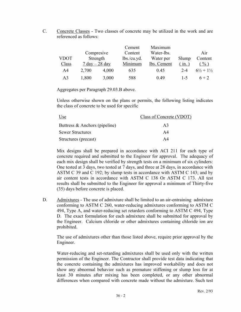
Rev. 2/93 36 - 2
C. Concrete Classes - Two classes of concrete may be utilized in the work and are referenced as follows:
VDOT Class
Compresive Strength
7 day – 28 day
Cement Content
lbs./cu.yd. Minimum
Maximum Water-lbs. Water per
lbs. Cement Slump ( in. )
Air Content
( % ) A4 2,700 4,000 635 0.45 2-4 6½ + 1½ A3 1,800 3,000 588 0.49 1-5 6 + 2
Aggregates per Paragraph 29.03.B above.
Unless otherwise shown on the plans or permits, the following listing indicates the class of concrete to be used for specific
Use Class of Concrete (VDOT)
Buttress & Anchors (pipeline) A3 Sewer Structures A4 Structures (precast) A4
Mix designs shall be prepared in accordance with ACI 211 for each type of concrete required and submitted to the Engineer for approval. The adequacy of each mix design shall be verified by strength tests on a minimum of six cylinders: One tested at 3 days, two tested at 7 days, and three at 28 days, in accordance with ASTM C 39 and C 192; by slump tests in accordance with ASTM C 143; and by air content tests in accordance with ASTM C 138 Or ASTM C 173. All test results shall be submitted to the Engineer for approval a minimum of Thirty-five (35) days before concrete is placed.
D. Admixtures - The use of admixture shall be limited to an air-entraining admixture
conforming to ASTM C 260, water-reducing admixtures conforming to ASTM C 494, Type A, and water-reducing set retarders conforming to ASTM C 494, Type D. The exact formulation for each admixture shall be submitted for approval by the Engineer. Calcium chloride or other admixtures containing chloride ion are prohibited.
The use of admixtures other than those listed above, require prior approval by the Engineer. Water-reducing and set-retarding admixtures shall be used only with the written permission of the Engineer. The Contractor shall provide test data indicating that the concrete containing the admixtures has improved workability and does not show any abnormal behavior such as premature stiffening or slump loss for at least 30 minutes after mixing has been completed, or any other abnormal differences when compared with concrete made without the admixture. Such test

Rev. 2/93 36 - 3
data shall be based on fresh concrete from the proposed supplier, using hatching equipment proposed for use on the project. When more than one admixture is used, each admixture shall be dispensed separately into the mix, and at different times during mixing, in accordance with the recommendation of ACI Committee 212. After system approval, no changes shall be made in hatching equipment or concrete constituents without approval of the Engineer.
E. Water - The water used in the preparation of the concrete shall be potable. The pH
of the water shall be between 4.5 and 8.5.
F. Reinforcing Steel - Reinforcing steel bars shall be deformed bars meeting the requirements of ASTM A 615, Grade 60. All reinforcing shall be rolled with special deformations or identifying marks indicating the ASTM Specification and Grade. Bars shall be free from defects, kinks and from bends that cannot be readily and fully straightened in the field. Test certificates of the chemical and physical properties covering each shipment shall be submitted to the Engineer for approval.
All provisions of the ACI 315 Detailing Manual, SP-66 for detailing reinforced concrete structures shall be followed in the preparation of placing drawings and bar lists, and for fabrication details, bends, tolerances and the like.
1. Reinforcing Steel Bars shall be supplied in lengths, which will allow them
to be conveniently placed in the work and to provide required lap at joints as shown. Dowels of proper length, size and shape shall be provided for tying walls, beams, floors and the like together.
2. Fabrication - Bent bar reinforcement shall be cold bent to the shape shown
on the plans. Unless otherwise specified or shown on the plans, bends shall be made in accordance with the requirements of the Manual of Standard Practice for Detailing Reinforced Concrete Structures (ACI 315). Truss bars for members 12 inches or less shall be fabricated to within a tolerance of 0 to minus 1/2 inch of the height shown on the plans.
G. Welded Wipe Mesh shall conform to ASTM A185. When used in continuously
reinforced pavement, wire mesh shall be deformed, furnished in flat sheets and shall conform to ASTM A497.
H. Forms
1. P1ywood - Forms for all interior exposed concrete surfaces and designed
areas of exterior exposed concrete surfaces shall be constructed of plywood not less than 5/8-inch thick for straight sections and 3/8-inch thick for curved sections. Plywood shall be five-ply for 5/8-inch or thicker and three-ply for 3/8-inch, made with a waterproof glue and

Rev. 2/93 36 - 4
manufactured especially for concrete formwork. Edges shall be square in both direct-ions, and adjoining panels shall match in thickness, width, and length. Full-size sheets of plywood shall be used, except where otherwise required or where smaller pieces will cover an entire area. Forms shall be placed so that markings will be symmetrical. Plywood shall be thoroughly oiled on contact faces and edges with raw linseed oil or other approved form lacquer.
2. Steel - If steel forms are proposed, their type shall be submitted to the
Engineer for approval; they shall not be used until such approval is secured. The forms shall be accurately constructed in modular sizes and in such minor multiple widths and lengths as will permit plates and readily distinguishable at the time bars are placed fillers to be erected to correct alignment, as required. Steel forms shall be coated before each use with a light, clear paraffin-base oil or other acceptable commercial preparation which will not discolor the concrete. Plates shall be wire brushed after each use.
3. Form Ties - Only form ties, hangers, and clamps approved by the Engineer
shall be used, and they shall be of such type that, after removal Of the forms, no metal will be closer than one inch from the surface. Wire ties will not be permitted. Lugs, cones, washers, or other devices that will leave holes or depressions at the surface of the concrete greater than 7/8-inch in diameter shall not be fitted within the forms. Ties, which are to be left in place, shall be provided with swaged washers or other suitable devices to prevent seepage of moisture along the ties. The spacing of form ties hangers, and clamps shall be strictly in accordance with the manufacturer's directions, and the removable portions shall be coated with cup grease or other approved material.
I. Water Stops and Expansion Joints: Water stops of the type and dimensions shown
shall be provided at each of the locations where they are shown on the plans. Details on the water stops or expansion joints shall be submitted to the Engineer for approval.
1. Steel water stops shall consist of 1/8" x 8" steel plate, braced with cross
struts to the reinforcing steel. Joints shall be lapped and continuously welded across the lap.
2. Monel water stops shall consist of 24 gauge monel metal sheet
approximately 15 inches in width formed with a V-shaped center with the edges bent to a 1/2-inch radius. All joints shall be lapped at least one (1) inch, riveted and soldered.

Rev. 2/93 36 - 5
3. Vinyl water stops shall have a web thickness of not less than 3/8 inch, a width of approximately 9 inches and with center bulb and 1-inch diameter bulbs on each end.
36.04 EXECUTION
A. Reinforcing Steel
1. Detailing Shop Drawings - The Contractor shall submit checked detailed reinforcing steel placing drawings and bar lists to the Engineer for approval.
Wall and slab reinforcing shall not be billed in sections. Complete elevations of all walls and complete plans of all slabs shall be shown, except that when more than one wall or slab are identical only one such elevation or plan is required. These plans and elevations need not be true views of the walls or slabs shown. Every reinforcing bar in a slab shall be billed on a plan. Every reinforcing bar in a wall shall be billed on an elevation. Sections shall be taken to clarify the arrangement of the steel reinforcement. All bars shall be identified, but not billed, on such sections. For all reinforcing bars, unless the location of a bar is clear, the location of such bar or bars shall be given by a dimension to some structural feature which shall be readily distinguishable at the time bars are placed. The reinforcing steel placing drawings shall be complete for placing reinforcement without reference to the design drawings, including the location of support bars and chairs.
Every reinforcing steel placing drawing and bar list shall be completely checked by the Detailer and corrected before submittal for approval. If, after reinforcing steel placing drawings and bar lists have been submitted to the Engineer for approval, a review reveals that the drawings and lists obviously have not been checked and corrected they will be returned to the Contractor for checking and correcting.
2. Delivery and Protection - Reinforcing steel shall be delivered to the work
in strongly tied bundles, and each group of both bent and straight bars shall be identified with a metal tag giving the identifying number corresponding to the reinforcing steel placing drawings and bar lists. All bars shall be properly stored in an orderly manner, at least 12 inches off the ground, and kept clean and protected from the weather after delivery at the site of the work.

Rev. 2/93 36 - 6
Reinforcing steel shall be delivered without rust other than that accumulated during transportation to the work. It shall, at all times, be fully protected from moisture, grease, dirt, mortar and concrete. Before being placed in position, it shall be thoroughly cleaned of all loose mill scale and ruse and of any dirt, oil grease coatings or other material that might reduce the bond. If there is a delay in depositing concrete, the steel shall be inspected and satisfactorily cleaned immediately before the concrete is placed.
3. Installation - Bars shall be cut to required length and bent accurately
before placing. Bars shall be bent in the shop unless written approval of field bending is obtained from the Engineer. If field bending is permitted, it shall be done only when the air temperature where the bending operation is performed is above 30 degrees F. No bars partially embedded in concrete shall be field bent.
Cleaning, bending and placement of reinforcement shall be in accordance with ACI 315, ACI 318 and CRSI "Recommended Practice for Placing Reinforcing Bars". Bars used for top reinforcement in slabs shall be placed to · vertical tolerance of plus or minus l/4-inch. All other reinforcement shall be placed to the tolerances given in ACI 318.
Bars shall be placed in the exact positions shown with the required spacing and shall be cross-wired securely in position at intersections to prevent displacement during the placing of the concrete. The bars shall be fastened with annealed wire of not less than 17 gauge or other approved devices. Spacing chairs of an approved shall be furnished and properly placed to support and hold reinforcing bars in position in all beams and slabs, including slabs placed directly on the suborned or work mate. Continuous hi-chairs shall not be used for support of top bars. Top bars shall be supported by means of individual hi-chairs that have welded cross ties or circular hoops to prevent spreading of the legs. Side form spacers shall be used against vertical or sloping surfaces to maintain specified concrete cover and cross-position of rebate. All bolsters, chairs and other accessories that come in contact with forms for exposed surfaces of concrete other than architectural surfaces shall be hot-dipped galvanized after fabrication or have plastic coated legs. Tension and compression lap splices shall conform to ACI 318 with all supplements. Splices at points of maximum tensile stress shall be avoided wherever possible. Temperature bars shall have the clear spacing shown. All bar splices shall be staggered with not more than Fifty (50%) Percent of the bars spliced in any one direction, unless otherwise shown. On any section of the work where horizontal bars run further than the length of the forms, the form or head against which the work ends shall be

Rev. 2/93 36 - 7
perforated at the proper places to allow the bars to project through a distance at least equal to the lap specified. The projecting ends, however, unless otherwise directed by the Engineer, shall be of different lengths so that in no place will laps in adjoining bars in the same plane occur opposite each other. All welded splices and cadweld coupler splices shall develop at least One Hundred Twenty-five (125%) Percent of the specified yield strength of the bar in tension. Welded splices shall be made by certified welders in accordance with AWS D12.1. All welded splices shall be approved by the Engineer prior to the work being done.
B. Formwork
1. Installation - The design and engineering of the formwork, as well as its
construction shall be the responsibility of the Contractor. Forms shall be designed, detailed and constructed in accordance with ACI 347 including all tolerances except as modified herein. Beams and girder soffits shall be erected with a camber as shown or as directed by the Engineer. Where camber is not given a minimum camber of 1/4-inch per 10-foot of span shall be provided. The forms shall be sufficiently braced, shored and wedged to prevent deflection.
External angles of walls, beams, pilasters, columns and girders shall he provided with 3/4-inch bevel strips. Forms for repeated use shall be supplied in sufficient number to ensure the required rate of progress. All forms shall be thoroughly cleaned before reuse and shall be inspected immediately before concrete is placed. Deformed, broken, or defective forms shall be removed from the work. Temporary openings shall be provided in forms at convenient locations to facilitate cleaning and inspection.
The entire inside surfaces of forms shall be oiled with a suitable form oil immediately before erection or else thoroughly wetted just prior to placing concrete. No form oil shall be permitted on the reinforcing steel. The Contractor shall be responsible for the adequacy of all forms and for remedying any defects resulting from their use, inspection and prior approval by the Engineer notwithstanding.
2. Minimum Clearances - Forms shall be placed and held in position so that
the concrete cover, as measured from the surface of the bar to the surface

Rev. 2/93 36 - 8
of the concrete, shall be not less than the following, unless otherwise shown.
Slabs
For top and bottom bars for dry conditions:
#11 bars and smaller 1 inch #14 and #18 bars 1½ inch Exposed to earth, water or weather and for bottoms bearing on concrete work mat:
#5 bars and smaller 1½ inches #6 through #18 bars 2 inches
Beams and Columns
For dry conditions:
Stirrups and ties 1½ inches Principle reinforcement 2 inches
Exposed to water or weather
Stirrups and ties 2 inches Principle reinforcement 2½ inches
Walls
For dry conditions:
Less than 12 inches thick 1 inch 12 inches or thicker 1½ inches
Exposed to water, weather, or in contact with ground 2 inches
Footings
At formed sides and ends, and bottoms bearing on concrete work mat
2 inches
At unformed sides and ends, and bottoms in contact with earth
3 inches
Tops of footings Same as slabs.
C. Concrete
1. Mixing
a. Hand mixing, on the job site, will be permitted for concrete batches not to exceed ½ cubic yard. The component materials shall be measured by placing them in a rigid container in the

Rev. 2/93 36 - 9
volumetric proportions of 1:2:2½, cement to fine aggregate to course aggregate. Water shall be added to produce a slump not to exceed 3 inches.
b. Transit Mixing - The concrete shall be mixed in a truck mixer.
Mixing shall begin immediately after all ingredients are in the mixer and shall continue for not less than 70 nor more than 125 revolutions of the drum or blades at not less than 14 nor more than 20 revolutions per minute unless otherwise directed by the Engineer.
Maximum time between introduction of cement to the mix and discharge, hours: Air Temperature Up to
80° F 80°- 90° F Above 90° F
Agitator Type Haul Equip-ment Class A3, General Use (Retarded)
2½ 2 1½
Other Classes and Usages (Retarded and Unretarded) 1½ 1¼ 1
Non-Agitator Type Haul Equipment – All Concrete 1 ¾ ½
c. Mixing Limitations: Placement of concrete shall not be initiated
when the air temperature is below 40 degree Fahrenheit in the shade, unless otherwise approved by the Engineer.
2. Placement - No concrete shall be placed after its initial set has occurred,
and no retempered concrete shall be used under any conditions. Concreting operations shall be continuous until the section, panel, or scheduled placement is completed. Should the concreting operations be unavoidably interrupted, construction Joints shall be formed at proper locations as specified.
Concrete shall be conveyed and placed with minimum handling and by means of buckets, buggies, chutes, pumps, or other approved equipment that will prevent segregation of the ingredients. The use of chutes is subject to the approval of the Engineer. Outlets of chutes, hoppers, and conveyor belts shall be provided with suitable baffles to prevent segregation. Apparatus shall be kept clean and flushed with water before and after each run. Concrete shall be deposited in the forms as close as
Rev. 2/93 36 - 10
possible to its final position and in no case more than 5 feet in a horizontal direction therefrom. Rehandling of concrete will not be permitted. Concrete shall be placed in layers shallow enough so that the previous layer is still soft when the next layer is added and the two layers can be vibrated together. Each layer shall not exceed 18 inches in depth, and the elapsed time between placing successive layers shall not exceed 45 minutes. Wall and column concrete shall be deposited through heavy duck canvas, galvanized steel, or PVC chutes equipped with suitable hopper heads. Chutes shall be of variable lengths so that the free fall of concrete shall not exceed 3 feet. Where required, illumination shall be provided inside the forms so that the concrete is visible from the deck and runways at the point of deposit. Aluminum chutes are unacceptable. Special care shall be taken to place the concrete against the forms, particularly in angles and corners, in order to prevent voids, pockets, and rough areas and to assure continuous contact of the entire surface of reinforcing steel and inserts with the' concrete. The concrete shall be rodded or spaded, if necessary, to work the coarse material away from the forms. Freshly placed exposed concrete shall be protected against damage from the elements or other sources.
3. Vibrating - All concrete shall be consolidated by means of mechanical
internal vibrators applied directly into the concrete in a vertical position.
The intensity and duration of vibration shall be sufficient to cause concrete to flow, to compact thoroughly and to embed reinforcement, pipes, conduits, and similar work completely. Vibrators shall not, however, be used to cause concrete to move more than a short distance horizontally. Vibrators shall be inserted and withdrawn at points 18 to 30 inches apart, and vibration shall be stopped immediately when a sheen of mortar first appears on the surface. The vibrating apparatus shall penetrate the previously placed layer so that the two layers shall be adequately bonded together but does not penetrate lower layers that have attained their initial set. Vibration shall be supplemented, if necessary, by forking or spading in the corners and angles of forms while the concrete is still plastic and workable. Vibrators shall operate at a speed of not less than 4,500 cycles per minute. Each tool shall weigh approximately 15 pounds and shall be capable of producing a visible effect upon concrete mixture with a 1-inch slump for a distance of at least 18 inches from the vibrator. A sufficient number of

Rev. 2/93 36 - 11
vibrators shall be on hand to assure that the incoming concrete can be properly compacted within 15 minutes after placing. Reserve vibrators shall be on hand when others are being serviced. No placement of any concrete shall be made with a single vibrator on hand.
4. Special Weather Considerations:
a. Warm Weather - For placement of concrete during hot weather, the
recommendations of ACI 305 shall be followed as modified herein. No concrete shall be placed if its temperature at the time of placement exceeds 90 degrees F and every effort shall be made to maintain lower temperatures. Where the temperature of the concrete being placed is consistently above 75 degrees F and a noticeable decrease in slump or an increase in mixing water demand occurs, a retarding admixture shall be used. Admixtures shall conform to the subsection entitled "Admixtures" and shall be used only with the written permission of the Engineer.
Unformed surfaces of concrete placed during hot weather shall be protected from drying by continuous moist curing for at least 24 hours. Curing shall be started as soon as the concrete has hardened sufficiently to withstand surface damage. If moist curing is not carried beyond 24 hours, the surface while damp shall be covered with a suitable heat-reflecting plastic membrane or sprayed with a white pigmented curing compound.
b. Cold Weather - Before placement of concrete, all ice, snow and
frost shall be completely removed from all surfaces to be in contact with the concrete. Concrete shall not be placed on a frozen subgrade. Surfaces to be in contact with the concrete shall be at a temperature as near as practical to that of the concrete being placed.
Set-accelerators will not be permitted for placement of concrete during cold weather. In general, concrete placed in the fall from the time of the first frost until the mean daily temperature at the site falls below 40 degrees F shall be protected from freezing for at least 24 hours after it is placed. Concrete placed in the spring after the mean daily temperature at the site rises above 40 degrees F shall be similarly protected until the danger of freezing is past. When mean daily temperatures at the site are generally below 40 degrees F, the temperature of the concrete as placed shall be not less than 50 degrees F except for mass concrete where the

Rev. 2/93 36 - 12
temperature of the concrete as placed shall be not less than 45 degrees F. Heating of aggregates or mixing water or both shall be used as needed to obtain these placement temperatures. The concrete temperatures as mixed shall not be permitted to exceed the placement temperature by more than 10 degrees F for air temperatures of 0 degree to 30 degrees F nor by more than 15 degrees F for air temperatures below 0 degree F. Concrete in place shall he maintained at a temperature of 50 degrees F by keeping forms in place, covering with insulated blankets, enclosures or combinations of these for the following minimum time intervals except that forms shall not be removed in less than the time specified in the subsection headed "Removal of Forms". Type II
Cement i) Footings and walls below grade and slabs on
grade 2 days
ii) Exposed walls and columns carrying no load 3 days
iii) Exposed floor slab, beams and girders above grade and partially loaded
6 days
Exposed surfaces of new concrete shall be protected from drying out. When dry heating is used for protection against low temperatures, exposed concrete surfaces shall be covered with an approved sheet material or membrane as specified in the subsection headed "Curing". Water curing may be used if icing problems can be avoided. Concrete shall be cured during the period of low temperature protection and for such additional time as approved by the Engineer. Curing shall conform to the requirements of the subsection headed "Curing". During periods of very cold weather, the Contractor shall continue the protection against low temperature during the extended curing period to prevent freezing of the concrete as approved by the Engineer. Concrete, which is to be exposed to freezing temperatures, shall be permitted to undergo some drying just prior to and during the period of adjustment to ambient cold-weather conditions. When protection against low temperatures is removed, the resulting

Rev. 2/93 36 - 13
temperature drop in any part of the concrete shall not exceed 5 degrees F per hour nor 40 degrees F for the first 24-hour period.
5. Curing - In general, the recommendations of ACI 308 shall he followed
for curing concrete.
a. Standard Portland cement concrete surfaces normally exposed to the atmosphere shall be protected against too rapid drying by curing for a minimum period of 7 days. When daily average temperatures are below 70 degrees F, the curing period shall be extended as required in the sub-section headed "cold Weather Requirements". The curing period shall commence immediately following the placing of the concrete. Curing shall be accomplished by the water method as approved by the Engineer, unless an alternate method is approved in writing. Should there by any delay in the application of the method of curing used, the concrete shall be covered with moistened burlap held in complete contact with the surface or kept wet by continuous sprinkling.
b. Water Curing - Water curing shall be accomplished by the use of
quilted covers wetted and applied to the concrete surface as soon as the forms have been removed, or in the case of slabs, as soon as the concrete has set up sufficiently to prevent marring of the surface. These quilted covers shall consist of an outer covering 1'3 of burlap or cotton or other approved material, and a needled, punched or sandwiched inner layer of cotton batting or other approved material, in all weighing not less than 20 ounces per square yard. The covering material shall be maintained in a thoroughly saturated condition and shall show the presence of free water between the mat and the surface of the concrete at all times throughout the curing period.
6. Joints and Bonding - Construction joints shall be made where indicated or
permitted. Such joints shall be located to insure stability, strength, and water tightness. All corners shall be built monolithically, and the concrete on either side shall be continuous to points shown or as directed.
At least 2 hours must elapse after placing concrete in the walls before depositing concrete in beams, girders, or slabs supported thereon.
Horizontal keyways shall be built to permit flushing water to escape from the keyways.
Joints shall have continuous, straight, and regular keys or grooves. Exposed concrete surfaces shall be brought to a true level line at the top of
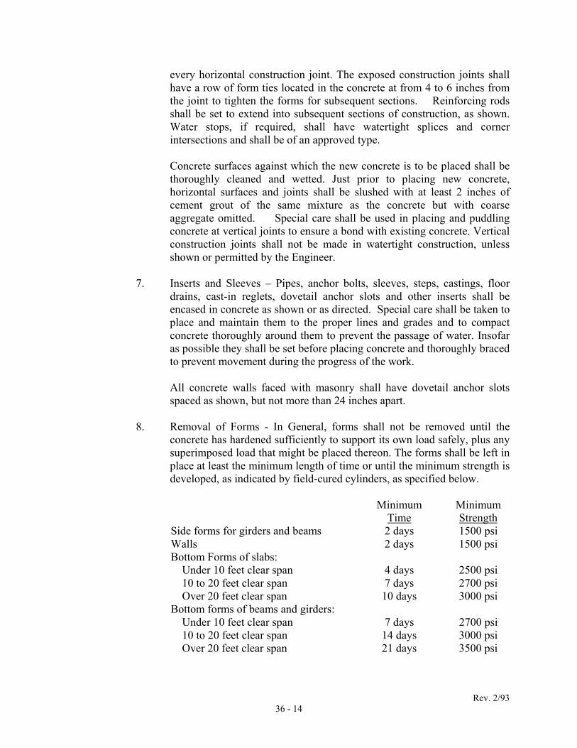
Rev. 2/93 36 - 14
every horizontal construction joint. The exposed construction joints shall have a row of form ties located in the concrete at from 4 to 6 inches from the joint to tighten the forms for subsequent sections. Reinforcing rods shall be set to extend into subsequent sections of construction, as shown. Water stops, if required, shall have watertight splices and corner intersections and shall be of an approved type.
Concrete surfaces against which the new concrete is to be placed shall be thoroughly cleaned and wetted. Just prior to placing new concrete, horizontal surfaces and joints shall be slushed with at least 2 inches of cement grout of the same mixture as the concrete but with coarse aggregate omitted. Special care shall be used in placing and puddling concrete at vertical joints to ensure a bond with existing concrete. Vertical construction joints shall not be made in watertight construction, unless shown or permitted by the Engineer.
7. Inserts and Sleeves – Pipes, anchor bolts, sleeves, steps, castings, floor
drains, cast-in reglets, dovetail anchor slots and other inserts shall be encased in concrete as shown or as directed. Special care shall be taken to place and maintain them to the proper lines and grades and to compact concrete thoroughly around them to prevent the passage of water. Insofar as possible they shall be set before placing concrete and thoroughly braced to prevent movement during the progress of the work. All concrete walls faced with masonry shall have dovetail anchor slots spaced as shown, but not more than 24 inches apart.
8. Removal of Forms - In General, forms shall not be removed until the
concrete has hardened sufficiently to support its own load safely, plus any superimposed load that might be placed thereon. The forms shall be left in place at least the minimum length of time or until the minimum strength is developed, as indicated by field-cured cylinders, as specified below.
Minimum
Time Minimum Strength
Side forms for girders and beams 2 days 1500 psi Walls 2 days 1500 psi Bottom Forms of slabs: Under 10 feet clear span 4 days 2500 psi 10 to 20 feet clear span 7 days 2700 psi Over 20 feet clear span 10 days 3000 psi Bottom forms of beams and girders: Under 10 feet clear span 7 days 2700 psi 10 to 20 feet clear span 14 days 3000 psi Over 20 feet clear span 21 days 3500 psi

Rev. 2/93 36 - 15
These times shall be increased if the concrete temperature following placement is permitted to drop below 50 degrees F.
The removable portion of form ties shall be withdrawn from the concrete immediately after the forms are removed. Holes left by such ties shall be filled with grout and the surface shall be finished with a steel spatula rubbed with sackcloth. On exposed interior surfaces of buildings, where appearance is important, some white cement shall be added in the patching grout.
Care shall be taken in removing forms, wales, shoring, supports, and form ties to avoid spalling or marring the concrete. Patching as may be necessary shall be started immediately after form removal.
9. Finishes:
a. Ordinary Surface Finish: All walls not exposed to view shall have
an ordinary surface finish. Following the removal of forms, fins and irregular projections shall be removed from all exposed surfaces and from all surfaces which are to be water-proofed, surfaces which are free from cavities having a diameter or depth greater than 1/4 inch need not be filled and burlap rubbed. Surfaces which contain cavities having a diameter or depth greater than 1/4 inch shall be cleaned, wetted, filled with mortar and burlap' rubbed. In the event of surface finish cannot be' performed immediately following the removal of the forms or before the surface of the concrete has become dry, the surface shall be kept wetted for a period of 1-3 hours, as directed by the Engineer prior to the application of the mortar.
All construction and expansion joints in the completed work shall be left free of all mortar and concrete. Joint filler shall be left exposed for its full length.
b. Rubbed Finish: All walls exposed to view shall have a rubbed
finish. After removal of forms, the rubbing of concrete shall be started as soon as its conditions will permit. Immediately before starting this work, the concrete shall be kept wetted for a minimum of three (3) hours. Sufficient time shall have elapsed before the wetting to allow the mortar used in the pointing of rod holes and defects to set thoroughly.
Surfaces to be finished shall be rubbed with a medium coarse carborundum stone, using a small amount of mortar on its face. The mortar shall be composed of cement and fine aggregate mixed
Rev. 2/93 36 - 16
in the proportions used in the concrete being finished. Rubbing shall be continued until all form marks, projections and irregularities have been. removed, all voids filled and a uniform surface obtained. The paste produced by this rubbing shall be left in place.
The final finish shall be obtained by rubbing with a fine carborundum stone and water. Rubbing shall be continued until the entire surface has a smooth texture and uniform color. After the final rubbing is completed and the surface has dried, it shall be rubbed with burlap and shall be left free from all unsound patches, paste, powder and objectionable marks.
c. Float Finish: The surface of all concrete slabs shall, unless
otherwise hereinafter specified, be given a float finish. The structural slab shall be brought to the established grade by screening. The surface shall be tested for irregularities with a straightedge. Irregularities shall be eliminated and the entire surface finished with a wood hand float or finishing machine.
d. Trowel Finish: All interior concrete floor slabs shall receive two
steel trowelings so as to obtain a hard dense surface free from pinholes and blemishes.
10. Grouting - Grout shall be placed under equipment bases, in conjunction
with the setting of anchors or dowels in holes drilled in concrete, and elsewhere as directed by the Engineer.
Grout for setting equipment bases, and similar uses shall be a flowable, prepackaged, nonshrink grout without dependence on gas expansion forces or enlargement of metal particles for its non-shrinking characteristics. There shall be no shrinkage below placement volume under ASTM C 827 and no drying shrinkage under CRD 588-76.
Grout for setting equipment bases and similar uses shall be Embeco 636 grout as made by Master Builders Company, Cleveland, Ohio; Propak as made by Profex Industries, Inc., or equal.
Grout for setting anchors, bolts, and similar uses shall be Embeco Pre-Mix 153 Grout, Protalico as made by Protex Imdustries, Inc., or equal.
36.05 TESTING AND INSPECTION: Slump tests, compression tests, air content
determinations, or tests on individual ingredients in the concrete mixture, will be conducted. The Contractor shall furnish all necessary assistance and materials for collecting specimens including standard slump cones and wax coated cylinder molds. Normally this will not be required for thrust blocks unless problems occur.

Rev. 2/93 36 - 17
The Contractor shall provide an independent testing laboratory to conduct tests on the concrete. The laboratory shall provide the certified results of these tests directly to the Engineer.
A. Compression Test - During the progress of the work, concrete compressive
strength tests shall be conducted. Sampling of fresh concrete shall be in accordance with ASTM C 172. Test cylinders shall be made and for the first 24 hours, cured and stored in a tightly constructed, firmly braced wooden box, constructed to maintain the temperature immediately adjacent to the specimens in a range of 60 to 80 degrees F and prevent loss of moisture from the specimens. The storage temperature shall be thermostatically controlled by means of stoves, heating cables, electric light bulbs or other approved means.
Loss of moisture shall be prevented by covering cylinders with wet burlap, damp sand or other approved means. Test cylinders cast in cardboard molds shall not be stored in contact with wet burlap, damp sand or any other material that will allow the outside surfaces of the mold to absorb water for the first 24 hours. Cylinder shall be removed from storage after 24 hours, and molds removed. After removal of molds, laboratory-cured cylinders shall be stored in a moist condition at a temperature of 65 to 75 degrees F until the time of test. After removal of molds, field-cured cylinders shall be stored in the structure as near the point of sampling as practicable, with the same protection on all surfaces as the structure which they represent. One strength test shell be made for each 50 cubic yards or fraction thereof for each mix design of concrete placed in any one day, except that in no case shall a given mix design be represented by less than 5 tests. Cylinders will be tested in accordance with ASTM C 39. Each strength test will consist of three laboratory-cured and one field-cured cylinders. One laboratory-cured cylinder will be tested at 7 days. Normally two laboratory-cured cylinders and the field-cured cylinder will be tested at 28 days. If the 7-day laboratory-cured cylinder is not satisfactory, one of the remaining laboratory-cured cylinders will be tested at 7 days instead of at 28 days.
Each strength test is the average strength of two cylinders from the same sample tested at 28 days. The average of the strength tests for any portion of a structure shall be equal to or greater than the strength specified, and at least Ninety (90%) Percent of all the tests shall indicate a strength equal to or greater than the strength specified. In cases where the average of the strength tests for any portion of the structure falls below the specified requirements, the Engineer may order a change in the mix proportions or water content for the remaining portion of the work and may require the Contractor to secure test specimens of the hardened concrete represented by these cylinders. The number of test specimens required to

Rev. 2/93 36 - 18
be taken shall be the same as the number of test cylinders specified to be made for each concrete placement. Specimens shall be secured and tested in accordance with ASTM C 42. If the specimen tests further substantiate that the concrete represented by the cylinders and specimens is below the specified strength requirements, the concrete shall be removed and replaced at the expense of the Contractor.
B. Slump And Air Entrainment - Slump tests shall be made in accordance with
ASTM C 143, at the same time cylinders are made or more frequently as directed by the Engineer. Tests to determine air content of fresh concrete shall be taken twice daily, at least 4 hours apart, in accordance with either ASTM method or with a testing device approved by the Engineer. Concrete with excessive slump or improper air content will be rejected and no additional concrete shall be delivered until the cause of the deficiency is determined and corrected.
36.06 COATINGS:
A. Floor Hardener: All concrete floor surfaces shall have applied a non-colored Master Builders Company "Saniseal" or approved equal. Hardener to be applied in accordance with manufacturer's recommendations.
B. Wet Well Coating: In addition to the use of stainless steel or aluminum straps and
appurtenances at and below the high water elevation in the wet well, the application of one coat of Epoxy Type EP-3B followed by one coat of Epoxy Type EP-3T shall be required.
36.07 MEASUREMENT AND PAYMENT: Concrete will not be measured, but will be
included in the Lump Sum bid price for the pumping station or unit price for fittings and/or pipeline.
Rev. 2/93 37 - 1
DIVISION 37
MASONRY 37.01 SCOPE: The work in this section includes the furnishing of all labor, materials,
equipment and other incidentals to construct the masonry walls, door and woodwork for the pumping station in accordance with the Contract Documents and BOCA code.
37.02 MATERIALS:
A. Concrete Masonry Units: Shall be hollow load-bearing concrete block walls conforming to ASTM C90, Grade N-I, of nominal sizes as shown on the plans. Block used in unprotected exterior walls and in walls below grade shall consist of normal weight aggregate conforming to ASTM 33. All other block shall consist of lightweight aggregate conforming to ASTM C331. All interior partition units shall meet UL requirements for two hour fire rated concrete masonry units. Lintels, bond beams and other special shapes shall be provided where indicated or required. Block shall be sound and free from cracks and other defects that interfere with proper placing, and shall have smooth, close-textured, and uniformly colored surfaces, suitable for exposed walls.
B. Brick: ASTM C216, Grade SW Type (FSS) brick for brick veneer shall be
standard size as selected by Owner, based on samples as provided in accordance with the General Conditions. An allowance of $150.00 per thousand shall be made by the Contractor.
C. Mortar:
1. Portland Cement: ASTM C150, Type 1 2. Sand: Clear, Sharp, graded from fine to coarse, ASTM C-144 3. Water: Clean and potable 4. Mixture: One (1) part cement, two (2) parts sand
D. Horizontal Joint Reinforcement: ASTM A-82, fabricated from cold drawn steel
wire. The wire shall be zinc-coated after fabrication by the hot-dip process in accordance with ASTM A-153, Class B-2. Reinforcement shall consist of two or more parallel longitudinal wires, not less than 0.1875-inch in diameter, weld connected with truss-type cross wires, not less than 0.1483-inch diameter at minimum 16 inches o.c. The out-to-out spacing of the longitudinal wires shall be 1-1/2 to 1-3/4 inches less than the actual width of the masonry wall. The distance between welded contacts of cross wires with each longitudinal wire shall not exceed 6 inches for smooth wire and 16 inches for deformed wire. Joint reinforcement shall be provided in flat sections, not less than 10 feet in length, except that corner reinforcements and other special shapes may be less in length.

Rev. 2/93 37 - 2
E. Reinforcing Bars for lintels, bond beams and elsewhere as required shall conform to ASTM A615 deformed, Grade 60.
F. Anchors and Ties: Galvanize anchors and ties after fabrication in accordance
with ASTM A153, Class B-l, B-2 or B-3.
1. Rigid Steel Anchors: ASTM A36, 1/4 inch by 1-1/2 inch with ends turned two inches up and two inches, down, not less than 16 inches long for eight-inch and four-inch walls, and not less than 24 inches long for twelve-inch walls. Maximum wall thickness at intersections shall govern anchor lengths.
2. Adjustable Anchors: Triangular anchors of ¼ inch diameter mill
galvanized wire and weld-on rod of ¼ inch diameter round bright basic wire. Select from one of the following:
Manufacturer Product A.A. Wire Products Co. Flex-O-Lok Heckman Building Products Nos. 315 & 316 Hohmann and Barnard, Inc. VWT & 359 Jim Taylor, Inc. Triangle-Ty
G. Control Joints: "Dur-O-Wall", regular rapid control joint or Hohmann and
Barnard, Inc., "Quadri-Seal", control joint, sizes as indicated or required.
1. Wire Mesh Ties: Tie wire, not lighter than 20-gauge, galvanized, in 1/2-inch mesh, and of suitable width and length.
2. Corrugated Metal Ties: Not less than 7/8-inch wide, approximately 6
inches long, and not lighter than 22 gauge.
H. Miscellaneous Flashing: Miscellaneous flashing, including thru-wall, lintel, sill, and flashing at heads of openings, shall be one of the following:
1. Thirty (30) U.S. Standard gauge stainless steel with ribs or deformations
designed to provide an interlocking mechanically keyed bond in the mortar bed to prevent movement in all lateral directions.
2. Five-ounce copper or 38 U.S. Standard gauge stainless steel factory
bonded between two layers of waterproof, rot and mold-resistant, and reinforced Kraft covering.
3. A dual metal core of copper bonded with asphalt to a of lead, factory
bonded between layers of waterproof, rot and mold-resistant and reinforced Kraft covering. Total metal core weight shall be 5 ounces.

Rev. 2/93 37 - 3
I. Masonry Grout:
1. Proportions: Parts by Volume. Measurement by shovel not permitted.
Portland Cement
Sand Coarse Aggregate
One Part 2½ Parts 1½ Part
(Maximum size 3/8”)
2. Mixing Grout: Mix materials in a mechanical batch mixer for a minimum of five minutes. Add sufficient water to provide a fluid mix.
37.03 MATERIAL STORAGE: All mortar materials shall be stored under cover in a dry
place so that damage from moisture, freezing and other sources are prevented. Masonry unit shall be piled on plank platforms in dry locations, and shall be protected with tarpaulins or other suitable material until laid in the wall. Reinforcement and other metal items shall be protected from the elements.
37.04 GENERAL: All masonry work shall be done by skilled craftsmen in a workmanlike
manner throughout. Exterior walls shall be completely waterproof. Masonry shall be loaded, unloaded, stored, and handled in such manner as to prevent chipping, scratching, or other damage. Slightly damaged masonry units may be used in areas not exposed to view; no chipped, marred, or otherwise damaged masonry units will be permitted where exposed to view in the finished work.
A. Submittals:
1. Test Reports: Submit to the Engineer two copies of tests reports certifying
that masonry units meet specified ASTM requirements as per the General Conditions.
2. Certificates: Submit to the Engineer certificates certifying that fire-rated
concrete masonry units meet specified UL requirements.
B. Tests: Using the services of an approved independent testing laboratory, test representative samples of each type of concrete masonry unit incorporated into the work. Test samples in accordance with ASTM C140. Manufacturer of concrete masonry units shall pay for all tests.
C. Certification: Manufacturer of fire-rated concrete masonry units shall certify that
fire-rates units have been manufactured in accordance with UL requirements for indicated rating. Base certification on inspections made by an approved independent testing laboratory. Manufacturer shall pay for all costs incurred in certifying fire-rates unite.

Rev. 2/93 37 - 4
37.05 ERECTION: Masonry shall be laid plumb, square and true to lines and dimensions. Courses shall be level with joints uniform and properly tooled.
A. General Requirements:
1. In laying masonry units, over-plumbing and pounding or corners and jambs to fit stretcher unite shall be avoided after units are set in position. Where an adjustment must be made after mortar has started to set, the mortar shall be removed and replaced with fresh mortar. If necessary to "stop-off- a horizontal run of masonry, rack back half block length in each course. Toothing will not be permitted. When work is resumed, remove loose units and clean contact surfaces of all mortar and debris.
2. Where fresh masonry joins masonry that has partially or totally set, the
exposed surface of the set masonry shall be cleaned, roughened and lightly wetted so as to obtain the best possible bond with the new work. All loose masonry and mortar shall be removed.
3. During erection, walls shall be kept dry by covering at the end of each day
or shutdown period with canvas or waterproof paper. Partially completed walls not being worked on shall be similarly protected at all times. Covering shall overhand at least 2 feet on each side of the wall.
4. Work by other trades, including door and window frames, louvered
openings, pipes, anchors, miscellaneous metal work, flashing, etc., shall be built in carefully and neatly as masonry work progresses.
Spaces around metal doorframes shall be filled solidly with mortar. Control joints with pre-molded filler strips set rigidly in place shall be provided where indicated. Keep the open space at expansion and control joints free of mortar by using a continuous wood or metal strip set temporarily in walls.
5. No masonry shall be laid when the temperature of outside air is below 40
degrees F. unless suitable means are provided to heat masonry materials and protect completed work from freezing. Protection shall consist of heating masonry materials to at least 40 degrees F., and maintaining an air temperature of above 40 degrees F. on both sides of the masonry for a period of at least 48 hours.
6. Do not wet units prior to setting. However, in drying weather-brush a
small amount of water on contact surfaces to obtain a good bond.
7. Lintel and bond beam units shall be reinforced as detailed and filled with masonry grout. Minimum bearing of lintels at each end shall be S inches unless otherwise noted.

Rev. 2/93 37 - 5
8. Forms and Shoring: Forms and shoring for beams and other members
supporting masonry and for reinforced masonry members shall conform to the shape, lines and dimensions of members indicated and shall be sufficiently rigid to prevent deflections which may result in cracking or other damage to supported masonry. Approved curing conditions shall be maintained, and forms shall remain on girders and beams not less than 10 days, and on slabs not less than 7 days, after completion of the members. No less than 16 hours shall elapse before uniform construction loads are applied to completed masonry members. Not less than 64 hours shall elapse before concentrated loads are applied.
9. Adequately brace walls against displacement during construction.
B. Concrete Masonry Units:
1. The first course of concrete masonry units shall be laid on a full bed of
mortar for the full width of' the unit; succeeding courses of block shall be laid with full mortar coverage on horizontal and vertical shells. Vertical joints shall be shoved tight. The bed joints of concrete masonry unit shall be formed by applying the mortar to the entire top surfaces of the inner and outer face shells, and the head joints shall be formed by applying the mortar for a width of about one-inch to the ends of the adjoining units laid previously. The mortar for joints shall be smooth, nor furrowed, and shall be of such thickness that it will be forced out of the joints as the units are being placed in position. Where anchors, bolts and ties occur within the cells of the units, such cells shall be filled with masonry grout as the work progresses. Metal latch shall be placed under cells before they are filled. Concrete brick shall be used for bonding walls, working out the coursing, topping out walls under sloping slabs, distributing concentrated loads, backing brick headers, and elsewhere as required.
2. Exposed Concrete Units: Concrete masonry units for exposed walls shall
be selected for undamaged edges and ends of the exposed surfaces, it is not intended that all units within any one wall or partition be perfect without slight cracks and small chips, but rather that discretion be used in selecting the units with closer matching faces and least imperfections for exposure to view. Special attention shall be given to placing the units plumb, parallel and with a properly tooled joint. Exposed surfaces shall be kept clean and free of blemishes. Bond pattern shall be as indicated and specified. Upon completion, and after grouting and point, exposed surfaces shall present a reasonably uniform appearance not unpleasing to the eye and suitable to receive decorative finish. Masonry units which exceed imperfections allowed by ASTM C-90 shall not be used in walls and partitions exposed to view.
Rev. 2/93 37 - 6
3. Reinforced Concrete Masonry Unit Walls: Walls shall be laid in such a manner as to preserve the unobstructed vertical continuity of cores to be filled. Cross webs adjacent to vertical cores that are to be filled with grout shall be fully embedded in mortar, to prevent leakage of grout, mortar fins protruding from joints shall be removed before grout is placed; the minimum clear dimensions of vertical cores shall be 2 inches by 3 inches. Reinforcing shall be positioned accurately as indicated.
As masonry work progresses, vertical reinforcing shall be rigidly secured in place at vertical intervals not to exceed 160-bar diameters. Horizontal reinforcing shall be embedded in grout as grouting proceeds. The minimum clear distance between masonry and vertical reinforcement shall not be less than 1/2 inch. Unless indicated or specified otherwise, splices shall be formed by lapping bars not less than 20-bar diameters and wire tying them together.
4. Exercise care in laying up units so that anchors, reinforcement and other
materials specified elsewhere will be built in as the work progresses. Reinforce and anchor masonry in accordance with these specifications, the drawings, and requirements of the applicable building code. Where conduit, outlet and switchboxes or other openings occur, cut masonry units neatly. Cut units with power-driven masonry saws only.
5. Concrete block shall be laid in running bond unless otherwise shown.
Joints shall be 3/8 inch. 6. Cutting of units shall be done with a power-driven masonry saw.
7. Wall and Partition Intersections: Unless indicated otherwise, partitions
shall extend from the floor to the bottom of the roof construction above. Walls and partitions shall be structurally bonded or anchored to each other and to beams and columns; partitions and interior walls shall be securely anchored or wedged to the construction above. Wedging shall be done with slate, metal, or clay tile shims, at least two days after the erection of the wall or partition, and the top joint shall be filled solidly with motor.
8. Openings and Accessories: Door and window frames, louvered openings,
anchors, pipes, ducts and conduits shall be built in carefully and neatly as the masonry work progresses. Ties and anchors shall be placed accurately as shown or herein specified, as the work progresses. Grouting of ties or anchors into hardened mortar or grout will not be permitted. Spaces around metal door frames shall be filled solidly with mortar. Structural steelwork, bolts, anchors, inserts, plugs, ties, lintels and miscellaneous metalwork specified elsewhere shall be placed in position as the work progresses.
Rev. 2/93 37 - 7
C. Jointing for Masonry: When mortar has become thumbprint hard, all exposed masonry joints shall be compressed and tooled with an approved jointer, unless otherwise specified. Width of Joints shall be as specified herein before. After jointing and when mortar is sufficiently hard, walls shall be rubbed lightly with burlap to knock off loose particles.
1. Interior concrete block shall have concave joints, unless otherwise noted.
2. Exterior solid split face masonry units shall have 3/8 inch raked joints.
3. Joints shall be uniform in thickness and the average thickness of any three
consecutive Joints shall be 3/8 to 1/2 inch, to be adjusted and approved as initial placement commences. Story poles or gage rods shall be made and approved prior to starting the work and shall be used throughout the work. Changes in coursing or bonding after the work is started will not be permitted. Exposed joints shall be tooled slightly concave with a round or other approved jointer, when the mortar is thumbprint hard. The Jointer shall be slightly larger than the width of the joint so that complete contact is made along the edges of the units, compressing and sealing the surface of the joint. Tools which cause discoloration shall not be used. Joints shall be tooled first. Joints shall be brushed to remove all loose and excess mortar. All horizontal joints shall be level. Vertical joints shall be plumb and in alignment from top to bottom of wall within a tolerance of plus or minus 1/2 inch.
Weep holes shall be provided at base of walls and other locations indicated. Unless indicated otherwise, weep holes shall be constructed of open masonry head joints spaced 24 to 32 inches apart.
D. Types, Proportions and Mixing of Mortar: Mortar types and proportions shall
conform to ASTM C-270.
1. Mortar Types:
a) Mortar for masonry in contact with earth shall be Type M. b) Mortar for exposed exterior walls and interior load bearing walls
shall be Type S.
c) Mortar for interior non-load bearing masonry partitions shall be Type N.
2. Mortar Proportions: Parts by volume.
a) Cement-Lime Mortar

Rev. 2/93 37 - 8
Type Portland Cement
Hydrated Lime
Sand (measure in Damp loose conditions)
M 1 ¼ Not less than S 1 ¼ to ½
N 1 ½ to 1¼
2¼ and not more than 3 times the sum of the volumes of cement and lime used.
b. Masonry Cement Mortar: Subject to approval of the Engineer,
mortar may be mixed with masonry cement as specified below.
Type Portland Cement
Masonry Cement Sand
M 1 1 6 S ½ 1 4½
N 0 1 3
3. Mixing of Mortar: Mortar ingredients shall be mixed in bins of an approved type, and shall be thrown in loosely and not packed or shaken down. Under no conditions shall mortar be re-mixed or allowed to stand over 45 minutes.
D. Cleaning:
1. Cleaning: During construction, care shall be taken continuously to keep
the exposed faces clean of mortar and other stains. When mortar joints reach thumbprint hardness and are tooled, the exposed work shall be brushed with a soft fiber brush to remove adhering mortar, and a wood paddle shall be used to remove more tenacious material. Do not wet concrete masonry units until mortar has thoroughly set. Clean masonry from scaffolding, not ladders. Bases of walls shall be protected from splash stains by covering the adjacent ground with sand, sawdust, or polyethylene. At the completion of the masonry work, holes in exposed masonry shall be pointed, and defective joints shall be cut out and tuck point solidly with mortar which has been retempered one to two hours after original mixing.
2. Exposed masonry shall be protected against staining from wall coverings
or other sources and excess mortar shall be wiped off the surface as the work progresses.
3. Upon completion of work, all exposed masonry, including concrete block,
shall be cleaned only with stiff brushes and water.

Rev. 2/93 37 - 9
E. Welded Wire Tie Reinforcement: Welded wire tie reinforcement shall be provided in every other course and in the first two courses above and below openings in walls of concrete masonry units. Reinforcement shall be continuous, except terminate reinforcing on each side of control joints. Reinforcement above and below openings shall extend not less than 24 inches beyond each side of openings. Reinforcement shall be provided in the longest available lengths, utilizing the minimum number of splices. Splices shall overlap not less than 12 inches. Welded "L" shaped assemblies, not less than 40 by 48 inches, and "T" shaped assemblies, not less than 32 by 32 inches, both of the same size members and the same construction as the straight reinforcement, shall be provided at corners and intersections of walls and partitions. Reinforcement shall be embedded in the mortar joints in such manner that all parts will be protected by mortar.
F. Anchors and Ties:
1. Rigid Steel Anchors: Install rigid steel anchors 16 inches on centers
vertically at all corners and intersections where prefabricated corner and tee wall reinforcing are not used.
2. Adjustable Anchors: Weld rod to steel members and set anchors in
horizontal joints of masonry wall spaced not more than two feet apart all columns and save purling.
G. Reinforcing Rods: Secure reinforcing rods to prevent displacement by masonry
grout.
H. Grout Placement: Grouting shall be performed from the interior side of walls, except as approved otherwise. Sills, ledges, offsets and other surfaces to be left exposed shall be protected from grout droppings. Grout falling on such surfaces shall be removed immediately. Grout shall contain sufficient water to be of pouring consistency and sufficiently fluid to flow into joints and around reinforcing without leaving voids. Grout shall be well stirred before placing to avoid segregation of the aggregate and shall be placed by pumping; or pouring from chutes, buckets with spouts, or other spouted containers. The maximum height of grout pour for concrete masonry shall be 4 feet. Grout shall be rodded or agitated thoroughly to eliminate voids, but with caution not to displace masonry from its original position, nor to stain exposed surfaces. Masonry displaced by grouting shall be removed and laid in realignment with fresh mortar. Pours shall be kept at 1½ inches below the top of masonry units in the top course, except for the finish course. Each pouring of grout shall be re-rodded or otherwise re-agitated 1 to 1½ hours after placing.
I. Miscellaneous Flashing: Install in strict accordance with the manufacturer's
printed instructions and details. Flashing at sills and heads of openings shall

Rev. 2/93 37 - 10
extend not less than four inches beyond jambs, with back and side edges turned up two inches to form a water dam.
Thru-wall flashing shall be provided in runs as long as practicable; end laps shall be not less than 4 inches and sealed in a watertight manner in strict accordance with the manufacturer's instructions, using an adhesive or high-grade asphaltic mastic as recommended by the manufacturer. Flashing materials through masonry walls shall be laid in the mortar joints so that both flashing faces are completely covered with mortar to provide the best bond possible. Care shall be taken not to puncture or otherwise damage the fleshing during installation, and all damaged flashing shall be replaced with new flashing.
J. Protection:
1. Cover top of exposed masonry wall and partitions at the end of each day's
work with waterproof paper or canvas. 2. Masonry shall be protected against freezing for at least forty-eight (48)
hours after being laid.
3. Unless adequate precautions against freezing are provided with the approval of the Engineer, no masonry shall be laid when the temperature is below thirty (32) degrees F. on a rising temperature or below forty (40) degrees F. On a falling temperature.
4. No construction shall be built on frozen materials.
5. All masonry surfaces shall be adequately protected from damage by the
operations of other trades on the job. And, portions of masonry which are damaged either structurally or in appearance shall be replaced.
37.06 MEASUREMENT AND PAYMENT: Masonry work will not be measured but will be
included in the lump sum bid price for the pumping station.

Rev. 2/93 38 - 1
DIVISION 38 DOORS, FRAMES AND MISCELLANEOUS METAL 38.01 SCOPE: The work in this section includes the furnishing of all labor, materials, equipment
and other incidentals for construction of the door, stairs, ladders, handrails, hatches, gratings and other miscellaneous metal items in accordance with the Contract Documents and BOCA Code.
38.01MATERIALS:
Doors and Frames: A. Doors shall be standard metal, full flush doors with metal frames. Southside doors
shall be similar to “Medallion” type (1¾” thick), as manufactured by the Ceco Corporation. Doors shall be recessed and reinforced in accordance with applicable industry standards to receive hardware as specified.
B. Hardware: Hinges shall be two ball-bearing type steel hinges, Ceco #2112-USP. All
outside doors shall be equipped with a heavy duty, cylindrical lockset. The door lock shall be a utility type; turnkey to open from outside; deadlocked when closed, cannot be left unlocked; turn-knob to open from inside, emergency exit safety requirements. Lock is to be master keyed for City Master Key No. D99699. Russwin Type 452, or any approved equal lock, unlocked by City Master Key. Contractor shall provide three (3) keys to the City.
C. Door Frames shall have a 2” face and a 5 ¾” depth unless otherwise shown on the
plans. Frames shall be recessed and reinforced to receive hardware, as specified. Frames shall be furnished with the necessary anchors and shall be prime painted.
D. Thresholds and Weather-stripping: Doors shall be equipped with weather-stripping
and interlocking threshold. The threshold shall be Ceco #4221 aluminum.
Miscellaneous Metals A. Structural Steel: Structural steel shall conform to the requirements of ASTM A36
and AISC. All steel shapes shall be fitted with clips, anchors, and base and angle plates as require for bolting, welding or anchoring into the concrete structure and masonry walls. The bolting, welding and anchorage shall be adequate to provide for the imposed loads as indicated on the drawings.

Rev. 2/93 38 - 2
B. Lintels: Furnish and install structural steel lintels over all openings of the type and sizes as indicated on the plans.
C. Shop Drawings: Shop drawing submittal is required for all items under this division
except lintels. Suppliers of ladders and stairs shall furnish certification that their design complies with all OSHA requirements.
D. Railing: Pipe railings shall be installed at locations as shown on plans. Pipe railings
shall be 1½ I.D. flush fittings, welded type ground smooth, standard weight steel pipe. Complete assembly to be hot dipped galvanized after fabrication for wet well railing. Railing stanchions shall be spaced not more than 6 feet apart. Stanchions to be secured to concrete as shown on plans. Rails shall be continuous through intermediate posts and standard handrail fittings shall be used throughout for screwed or welded connections. Railing shall be set in sleeves in floor and bolted to masonry walls.
E. Spiral Stairway: Where plans call for spiral stairway, Duvinage Series 300 with
open raisers and checkered treads, or approved equal, shall be used.
F. Ladders:
1. Wet Well Ladders shall be 18” wide and shall have 2½” x 3/8” steel siderails and ¾” diameter rods for treads. Ladder to be bolted to wall with angle clips. Ladders to be hot dipped galvanized after assembling.
2. Pump Room Ships Ladder shall be 2 feet wide and shall have 6” x ¼” steel
siderails and 6” x ¼” checkered treads. Handrails shall be 1¼” diameter and welded to siderails. Ladder to be anchored in place with angle clips and bolts.
G. Grating shall be extruded galvanized steel of the sizes shown on the plans. Grating
shall be “I-Bar” as manufactured by Irving Grating and shall be furnished with perimeter bars. Grating shall be capable of supporting a live load of 150 pounds per square foot.
H. Entrance Hatches shall be Richards Foundry or equal, with design numbers as
indicated on the drawings.
I. Galvanizing shall be in accordance with Section 415 of VDOT Road and Bridge Specifications.
38.03 SUBMITTALS: (Doors and Frames) Shop drawings shall be submitted for all items provided under this division.
Rev. 2/93 38 - 3
38.04 EXECUTION: (Doors and Frames) Doors shall be installed plumb, square and level. Door frames shall be securely anchored in place with joints fully caulked. Doors shall be adequately protected from damage during construction. All coatings, protective covering materials, etc., shall be removed after construction, doors and door frames cleaned and painted as specified under “Painting”.
38.05 MEASUREMENT AND PAYMENT: Payment will be included in the lump sum bid price
for the pumping station.
39 - 1
DIVISION 39 ROOFING AND WOOD WORK 39.01 SCOPE: The work in this section includes the furnishing of all labor, materials, equipment
and other incidentals for construction of the roof and woodwork for the pumping station in accordance with the Contract Documents.
39.02 MATERIALS AND EXECUTION:
A. Built-up Roofing: If built-up roofing is indicated on plans, the roof surface shall have a 20 year built-up roof. Roofing shall be a Barrett "Specification" or approved equal roof installed in accordance with the manufacturer's Specifications for application upon the particular type of roof deck being roofed.
B. Flashing: Flashing shall be in accordance with Barrett Specifications for 20 year
bondable roof. Flashing shall be 16 oz. copper. Flashing around pipes and other obstructions shall be in accordance with Barrett Specifications.
C. Asphalt Shingles: Asphalt shingles shall be Fire King FGA Seal-O-Matic shingles
(240#/square) as manufactured by Johns-Manville Company or equal, or Bird "Architect 70" fiberglass shingles (340#/square). Shingles shall be installed in accordance with the manufacturer's instructions. Cracked shingles with broken corners shall not be used. Shingles shall be well lapped and nailed to provide a watertight surface. The color shall be selected by the Owner and approved by the City.
D. Wood Work: Lumber shall be sound, free from warp and dressed and each piece
shall be grade marked. All lumber used for framing shall be No. 2 Southern Pine or better. Molding and trim shall be primed and wrapped with aluminum as shown on the plans. Plywood shall be sheathing grade. Roof rafters, joints and other framing shall be closely fitted, set to required lines and securely spiked in place. Ridges shall be straight with true intersections of roof planes.
39.03 SHOP DRAWINGS - Shop Drawings shall be submitted for all items provided under this
division. 39.04 MEASUREMENT AND PAYMENT: Payment will be included in the lump sum bid price
for the pumping station.

Rev. 2/93 40 - 1
DIVISION 40
PUMP STATION SITE WORK AND LANDSCAPING 40.01 SCOPE: The contractor shall furnish all labor, materials, equipment, and supplies; and
shall perform all work necessary for the installation of landscaping as shown on the plans for the pump station site and the site work for the pump station. This work shall include clearing and grubbing; earthwork; concrete driveway; sidewalk, and entrances; landscaping, grading and drainage pipe, topsoil, seeding, erosion and sediment control; water service installation, cleanup, and any other restoration work required due to construction activity.
40.02 MATERIALS: (Site work) See Applicable Divisions
(Landscaping)
A. Trees and Shrubs: Provide trees and shrubs grown in a recognized nursery in accordance with good horticultural practice. Provide healthy, vigorous stock grown under climatic conditions, similar to conditions in the locality of the project and free of disease, insects, eggs, larvae, and defects such as knots, sun-scald, injuries, abrasions, or disfigurement.
1. Sizes: Provide trees and shrubs of the size shown or specified. Trees and
shrubs of larger size may be used if acceptable to Engineer, and if sizes of roots or balls are increased proportionately.
B. Mulch: Provide hardwood bark mulch in accordance with State Nursery
Guidelines. Size of pine bark chips to be between 1/2" and 2' size. C. Inspection: The Engineer reserves the right to inspect trees and shrubs either at
place of growth or at site before planting, for compliance with requirements for name, variety, size and quality.
D. General: ship landscape materials with certificated of inspection as required by
governmental authorities. Comply with governing regulations applicable to landscape materials.
E. Do Not Make substitutions. If specified landscape material is not obtainable,
submit to the Engineer proof of non-availability and proposal for use of equivalent material. When authorized, adjustment of contract amount will be made.

Rev. 2/93 40 - 2
40.03 EXECUTION:
(Site Work)
A. Clearing and Grubbing: See Division 19
B. Earthwork:
1. Excavation and Backfill: Excavation shall conform to the lines and grades shown on the drawings and established by the Contractor. Excavation shall not be carried below the established grades and any excavation below the required level shall be backfilled, and tamped at the Contractor's expense unless directed by the Engineer.
The Contractor shall do all sheeting, bracing, and shoring necessary to perform the work and protect workers and excavations as required to conform to all governing laws and ordinances and as directed by the engineer. All necessary dewatering and pumping shall be performed in such a manner as to keep the excavation in a satisfactory condition. The Contractor shall conduct his operations such as to provide adequate drainage of the construction area and adjacent areas affected by construction through temporary ditching, piping, or other means as may be appropriate. Drainage shall not be impeded by construction operations.
2. Backfilling shall be done with material free from large clods and foreign
matter, and shall evenly and carefully be placed and tamped in a maximum of twelve (12) inch horizontal layers. Tamping shall be performed using suitable pneumatic compactors or an approved equal. Compaction equipment specifically designed for these purposes must be present and operational at the job site and shall be utilized to obtain uniform compaction. Where settlement is important and where excavation has been made through permanent pavements, curbs, and driveways, and sidewalks, or where structures are undercut by excavation, it shall be the Contractor's responsibility to provide compaction of the backfill material to ninety-five percent (95%) of its maximum density at plus or minus twenty percent (20%) of its optimum moisture. Surplus material shall be disposed of by the Contractor in accordance with all Federal, State, and local laws and regulations.
3. Compaction Tests: The City or its authorized representative reserves the
right to perform compaction tests on any or all portion(s) of backfill placed in the trench at no costs to the Contractor. However, in the event the compaction of this backfill is not in compliance with the specification, Section 10.03. B, then the Contractor shall take corrective measures at no

Rev. 2/93 40 - 3
costs to the City to bring the backfill within the limits of the Specifications, Section 10.03.B. The Contractor shall then be responsible for reimbursing the City all costs associated with the performance of compacting test(s) in those sections of the backfill that failed the compaction test(s). However if the tests should indicate compaction within the required limits, the City will then be responsible for said costs.
4. Should it be determined that removal of sheeting in excavated areas might
endanger adjacent properties or structures, the Engineer may direct that the sheeting be left in place. In such instances, sheeting will be cut off one (1) foot below grade and left in place. Backfilling will be performed in accordance with appropriate sections of this specification.
C. Pipe Work: Pump station contractor shall terminate the pump station pipe work 3'
outside the building wall, after sheet pile removal, connection to the gravity sewer, forcemain, and the emergency pump connection will be completed by the pipeline contractor.
D. Concrete Driveway, Sidewalk, and Entrances: See Division 22.
E. Drainage Pipe: See Division 10. F. Erosion and Sediment Control: See Division 23.
G. Topsoil, Seeding and Grading: All unpaved, and disturbed areas due to the
contractor's activities shall be graded, topsoiled, seeded, and restored. Grading shall be done in accordance with the proposed grades shown on the plan. Topsoil, seeding and restoration work shall be done in accordance to Division 20.
H. Water Service Installation:
1. Materials: Shall conform to Division 33 for service pipe, corporation
stops, angle valve, meter box and service saddle.
a. Dual Check Valves: Dual check valves shall be watts No. 7.
b. Hose Bib:
1) Hose bib vacuum breaker shall be Watts No. 8 or 8A or approved equal.
2) Hose bib shall be Crane #438 valve or approved equal with
male hose threads for 3/4" hose connection.

Rev. 2/93 40 - 4
2. Installation:
a. The installation of water service connections shall be in accordance with the detail shown in City Standard PFM Vol. II.
b. Meter boxes shall be placed at the end of each service line with
their tops set at finished grade.
c. Service lines shall have a minimum of 24" to a maximum of 36" cover from the top of the tubing to finished grade. The top of the angle curb stop/valve shall be set at an elevation 12" below finished grade.
I. Cleanup and Restoration Work: Provide cleanup and restoration work in
accordance to the General Conditions, Supplemental Conditions, and these technical specifications.
(Landscaping)
A. Trees and Shrubs: Provide freshly dug trees and shrubs. Do not use trees or shrubs which have been heeled-in. Do not prune prior to delivery. Do not bend or bind-tie trees or shrubs in such manner as to damage bark, break branches or destroy natural shape. Provide protective covering during delivery.
B. Deliver trees and shrubs after preparations for planting have been completed and
plant immediately. If planting is delayed more than 6 hours after delivery, set trees and shrubs in shade, protect from weather and mechanical damage, and keep roots moist.
C. Do not remove container-grown stock from containers until planting time.
D. Layout individual tree and shrub locations, and areas for multiple plantings.
Stake locations and outline areas and secure Engineer's acceptance before start of planting work. Make minor adjustments as may be requested.
E. Utilities: Determine location of underground utilities and perform working
manner which will avoid possible damage. Hand excavate, as required, to minimize possibility of damage to underground utilities. Maintain grade stakes set by others until removal is mutually agreed upon by all parties concerned.
F. Excavate pits, beds and trenches with vertical sides and with bottom of excavation
slightly raised at center to provide proper drainage. Loosen hard soil in bottom of excavation.
1. For bare root trees and shrubs, make excavations at least 1' - 0" wider than
root spread and deep enough to allow for seeding of roots on a layer of

Rev. 2/93 40 - 5
compacted backfill and with collar set at same grade as in nursery, but 2" below finished grade at site.
Allow for 9" setting layer of planting soil mixture.
2. For balled and burlapped (B&B) trees and shrubs, make excavations at least twice as wide as the ball diameter and equal to the ball depth, plus the following allowance for setting of ball on a layer of compacted backfill:
Allow for 3" setting layer of planting soil mixture.
3. For container grown stock, excavate as specified for balled and burlapped
stock, adjusted to size of container width and depth.
Dispose of subsoil removed from landscape excavations. Do not mix with planting soil or use as backfill. Fill excavations for trees and shrubs with water and allow to percolate out before planting.
G. Set balled and burlapped (B&B) stock on layer of compacted planting soil
mixture, plumb and in center of pit or trench with top of ball at same elevation as adjacent finished landscape grades. When set, place additional backfill around base and eliminate voids and air pockets. When excavation is approximately 2/3 full, water thoroughly before placing remainder of backfill. Repeat watering until no more is absorbed. Water again after placing final layer of backfill. Remove burlap from sides of balls; retain on bottoms.
H. Set bare rootstock on cushion of planting soil mixture. Spread roots and carefully
work backfill around roots by hand and puddle with water until backfill layers are completely saturated. Plumb before backfilling and maintain plumb while working backfill around roots and placing layers above roots. Set collar 1” to 2” below adjacent finish landscape grades- Spread Cut roots without tangling or turning up to surface. Cut injured roots clean, do not break.
I. Set container grown stock as specified for balled and burlapped stock, except cut
cans on 2 sides with an approved can cutter; remove bottoms of wooden boxes after partial backfilling so not to damage root balls.
J. Mulch pits, trenches and planted areas. Provide not less than 3 inch thickness of
mulch and work into top of backfill and finish level with adjacent grades.
K. Prune, thin out and shape trees and shrubs in accordance with standard horticultural practice. Prune trees to retain required height and spread. Unless otherwise directed by the Engineer, do not cut tree leaders, and remove only

Rev. 2/93 40 - 6
injured or dead branches from flowering trees, if any. Prune shrubs to retain natural character and accomplish their use in the landscape design. Required shrub sizes are the size after pruning.
40.04 MEASUREMENT AND PAYMENT: Pump Station site work will not be measured but
included in the lump sum bid price for the pumping station.

41 - 1
DIVISION 41
PAINTING 41.01 SCOPE: The work in this section includes furnishing all labor, materials,
equipment and other incidentals to complete the painting for the pumping station in accordance with the Contract Documents.
41.02 MATERIALS:
A. Masonry Application:
1. Interior Concrete Block: One Coat block filler approved by paint manufacturer and two coats Ramuc Non-Lead Utility Enamel (1 gal. per 250 sq. ft.).
2. Exterior Foundation Walls (up to a line 6" below finish floor) and
Wet well: Two coats Poxitar (1 gal. per 160 sq. ft.).
B. Metal Application:
1. Submerged (except chains): Shop Primer with one coat of Poxitar Primer (1 gal. per 250 sq. ft.); one coat grease coating (1 gal. per 40 sq. ft).
2. Submerged (chains, gates, other moving parts): Shop Primer, one
coat No. 621 (1 Gal. per 250 sq. ft.); one coat grease coating (1 gal. per 40 sq. ft.).
3. Non-Submerged: One coat Primer No. 621 (1 gal. per 250 sq. ft.)l,
two coats Rust-Oleum per following color schedule:
a. Green Metallic Alum. - Rust-Oleum #1030 Pumps, cast iron sewage piping, sump pump piping, pump bleeding lines (if copper, do not paint), located in pump room level of wet well/dry well type station.
b. Light Gray - Rust-Oleum #902
Pump motors, vent fans, air ducts, inside floor hatches and frames, inside floor grates, metal doors inside and outside, door frames, window frames, wire window covers, steel beam drive shaft support, electric meter cover and box, inside hand rails, metal stairs, pumps and cast iron piping when in motor room level of positive suction lift stations.

41 - 2
c. Bright Red - Rust-Oleum #11-19 Valve wheels, valve handles, check valve cover plates end counter weights, electric conduit, junction boxes, light switches and any electrical device not defined. Where indicated on plans, electrical devices shall he stained with olympic oil-base stain, with choice of color and type (semi-transparent or solid) by City.
d. Forest Green - Rust-Oleum #1282
Emergency force main connection and valve box, City water piping, potable water lines (if copper, do not paint).
e. Black - Rust-Oleum #11-5
Wet well steps, outside hand rails, outside piping, wet well rails, force main piping in wet well, outside hatches and covers, any metal outside or in corrosive area not listed in paint chart to be painted.
f. Bright Alum. - Rust-Oleum #470
Pump drive shafts and shaft couplings.
g. DO NOT PAINT NAMEPLATES: Cover with clear plastic or varnish Rust-Oleum #717 Clear-Sele, if needed.
h. A paint of equal quality will be accepted subject to
approval by the Engineer provided it is a direct match and it does not have a lacquer vehicle but an oil base vehicle.
4. Galvanized Metal, Copper Pipes, Non-Ferrous Metal: Galvanized
metal, with the exception of galvanized steel pipe shall not be painted. Galvanized steel pipe inside buildings and exposed shall be treated with one coat of Inertol Metal Passivator No. 35 (1 gal. per 300 sq. ft.) prior to priming. Copper pipe and tubing shall not be painted. Non-ferrous metal, unless a minor part of an item that requires painting shall not be painted. Galvanized handrails shall not be painted.
C. Wood Application:
1. Interior Wood Surfaces: One coat of Inertol Undercoat No. 623
(1 gal. per 400 sq. ft.) and two coats of Glamortex Non-lead Enamel (1 gal. per 400 sq. ft. per coat).
2. Exterior Wood Trim, Etc.: To be primed and wrapped in aluminum
as shown on the construction plans.
41 - 3
41.03 EXECUTION:
A. All interior and exterior wood surfaces, mechanical equipment, pumps, piping, interior masonry, and miscellaneous metal items except those specified for galvanized finish shall be painted with two coats of paint (or more as specified above) of the types specified herein using colors as directed by the Engineer. Exterior masonry shall be painted only if brick veneer is not used. Interior concrete floors shall not be painted.
B. Preparation of Surfaces:
1. All surfaces shall be thoroughly cleaned of all moisture, dirt, oil,
grease, rust, scale, pitch, tar, asphalt, and other foreign matter prior to painting.
2. All sap wood and knots shall receive a thin coat of shellac before priming or painting.
3. Masonry shall be fully cleaned, brushed free of loose particles, and
pointed prior to being painted.
4. Sand all wood thoroughly, removing machine marks and any other defects prior to painting or finishing. Putty all nail holes, joints, cracks, and other depressions in wood surfaces, prior to finish coats of painting. Do not sand rough-sawn trim.
5. Remove all rust or other damage to shop coat on ferrous metal
surfaces. Re-prime damaged metal surfaces, bare metal surfaces with red lead paint prior to painting.
6. The contractor shall not paint any surfaces that are not in proper
condition for painting. The Contractor shall notify the Engineer in writing before any painting or finishing of such surfaces is commenced. The application of the first coat of job painting of finishing shall be construed as an acceptance of the surface to which it is applied and shall be considered as waiving all claims of the Contractor in regard to proper condition of the surfaces so painted or finished.
C. Application:
1. All materials shall be applied by skilled mechanics, in strict
conformance with manufacturer’s directions.
41 - 4
2. All materials shall be evenly spread, smoothly flowed on, and brushed out thoroughly, without running or sagging. Exterior paint and masonry shall be brushed thoroughly into voids and crevices in surfaces to produce a thick coating.
3. PAINT APPLICATIONS SHALL BE BY BRUSH, ROLLER, OR
SPRAY.
4. All lines of demarcation between paint of different colors or shades and between painted and unpainted surfaces shall be carefully drawn and shall be free from wavy lines, blurred edges or overlaps.
5. Sand all woodwork between coats, except rough-sawn trim.
6. Completed surfaces shall be uniform in gloss, finish, sheen and
color and shall be free from runs, sags, crawls, brush marks and other defects.
7. Vary tint of succeeding coats slightly to permit identification of
coats. 41.04 MEASUREMENT AND PAYMENT: Painting will not be measured, but will
be included in the lump sum bid price for the pumping station.

Rev. 2/93 42 - 1
DIVISION 42
PIPING, VALVES & FITTINGS 42.01 SCOPE: The work in this section includes the furnishing of all labor, materials,
equipment and other incidentals to provide the piping, valves and fittings for the pumping station in accordance with the Contract Documents.
42.02 MATERIALS:
A. Pipe and Fittings:
1. Ductile iron pipe shall conform to the requirements of Section 33.02A, except as noted below:
a. All pipe to be flanged in accordance with AWWA C115. All
flanges to be ductile iron.
b. Non-submerged, interior piping shall be prime coated in accordance with Division 41. Submerged interior pipe and all buried exterior pipe shall be either asphaltic or epoxy coated on the outside.
c. Fittings shall be flanged in accordance with AWWA C115.
d. Gaskets shall be one-eighth (1/8") inch thick and similar to
Durable Garlock.
e. Interior coating on all pipes shall be asphaltic with no cement lining.
2. Copper Pipe:
a. Exterior shall conform to the requirements of Division 33.04
A.3.A.
b. Interior shall be Type-L Hard conforming to ASTM 8-88. Fitting shall be sweat-type, unless otherwise noted.
3. Plastic pipe shall conform to the requirements of AWWA C-901 and shall
be straight.
4. Galvanized pipe shall be of the hot-dipped type in accordance with ASTM A-53.

Rev. 2/93 42 - 2
B. Valves:
1. Gate valves shall conform to the requirements of Section 34.02, except as noted below:
a. All interior valves shall be wheel-operated.
b. Interior valves with operating nuts more than 48 inches below
finished grade (gravity sewer influent valve) shall be equipped with extensions fastened to the operating nut and shall have an operating nut on top of the extension not more than 18 inches below grade.
c. All interior non-submerged valves shall be prime coated in
accordance with Division 41.
d. All interior submerged valves and all exterior valves shall receive the manufacturer's standard coating.
2. Check valves shall be horizontal swing, full-opening iron body bronze
mounted, weighted lever check. Valves with flanged ends as manufactured by Darling, or approved equal. The lever counterweight shall be adjustable and shall cause positive closing at pump shutoff.
C. Pipe Sleeves: Provide cost or ductile iron wall sleeves as shown on the plans or
whenever a pipe passes through the floor, roof slab or walls. Sleeves shall be of sufficient size to allow free passage of the pipe. Ends of sleeves are to be flush with slab and wall surfaces. All paint shall be removed before installation to insure watertight seal on exterior of sleeve. Sleeve shall be caulked around pipe to prevent leakage.
D. Wall Pipe: Provide wall pipe as shown on the plans wherever ductile iron pipe
lasses through the floor, walls or ceiling of the station. Wall pipe shall conform to the requirements of AWWA C-110. All paint to be removed from exterior prior to installation so as to prevent leakage.
E. Pipe Hangers, Inserts and Supports: Heavy adjustable wrought iron or malleable
iron pipe hangers shall be provided. Hanger rods shall be of wrought iron, sized as noted:
Pipe Diameter Rod Diameter
≤ 2 inch 3/8” 2½ to 4 inch ½”
6 inch 5/8” ≥ 8 inch ¾”
Rev. 2/93 42 - 3
F. Hose Bib: Shall be Crane #438 valve or approved equal with male hose threads for 3/4" hose connection.
G. Backflow Preventer:
1. Pressure type vacuum breaker shall be Watts No. 800 or approved equal;
2. Hose bib vacuum breaker shall be Watts No. 8 or 8A or approved equal.
H. Shop Drawings: Shall be submitted for all materials provided under this section.
42.03 INSTALLATION:
A. Horizontal Overhead Runs of Pipe shall be hung with pipe hangers not more than six feet apart. Use hook hangers fastened with expansion screws to walls to support piping running adjacent to walls. Hanger rode to be provided with adjustable swivel pipe rolls. Vertical run supports shall not be spaced more than 10 feet apart.
B. Valves shall be installed plumb unless otherwise shown on the plans.
C. All Joints shall be firmly bolted with flanges aligned.
42.04 MEASUREMENT AND PAYMENT: Piping, valves, fittings and appurtenances will
not be measured but are included in the lump sum bid price for the pumping station.

2/93 43 - 1
DIVISION 43
ELECTRICAL AND CONTROLS 43.01 GENERAL: Work to be performed under this section includes furnishing all
labor, equipment, material, incidentals and appurtenances for the electrical systems and circuits supplying power, lighting, general purpose uses, instrumentation and control for the project as specified hereinafter and/or shown on the plans. It is the intent of the plans and specifications to describe a complete and working electrical system and to prescribe for the complete electrical installation and testing of the equipment and devices specified under other sections of the specifications and/or shown on the plans. The Contractor is charged with familiarizing himself with these and other plans and specifications prior to submitting a bid. No extra payment will be made for incidental work not specifically called for, but which is necessary for the proper installation of equipment and functioning of the system.
A. Equipment: The Contractor shall furnish and install all equipment
obviously of an electrical nature as well as those items specifically called out by manufacturer's names on the plans and in the specifications.
B. Workmanship: Workmanship shall be of the highest quality and no
substandard work will be accepted. All equipment furnished by the Contractor shall be new and in good condition.
43.02 APPLICABLE SPECIFICATIONS, CODES AND STANDARDS:
A. The latest effective publications of the following standards, codes, etc., as applicable, form a part of these Specifications the same as if written fully herein and shall be followed as minimum requirements. Minimum requirements shall not relieve the Contractor of the responsibility of furnishing and installing higher grade materials and workmanship than therein specified.
1. City of Chesapeake Building, Electrical and Fire Codes. 2. National Electric Code.
3. Standard Rules of the Institute of Electrical and Electronic
Engineers.
4. Service Rules and Regulations of Virginia Power.
5. National Electrical Manufacturer’s Association.

2/93 43 - 2
6. State Fire Safety Regulations.
7. Virginia Occupational Safety and Health Administration
(VOSHA).
B. The Contractor shall give all required notices, obtain all necessary permits and pay all required fees.
43.03 DRAWINGS: These Specifications are accompanied by floor plans and details
of the building electrical systems, and what is called for by one shall be as binding as called for on both. The drawings indicate diagrammatically the extent of the work, so the Contractor shall examine the architectural, structural, and mechanical drawings to avoid conflict with other trades. Minor variations in location of equipment shall be made upon written approval of the Engineer at no additional charge.
43.04 ELECTRICAL CONSTRUCTION METHODS:
A. Construction Methods: The methods are generally diagrammatic and the Contractor shall harmonize his work with that of other trades so that interferences between conduits, piping, equipment, architectural and structural work will be avoided. All necessary offsets in raceways, fittings, etc., required to properly install the work shall be furnished so as to take up minimum space and all such offsets, fittings, etc., required to accomplish this shall be furnished and installed by the Contractor without additional expense to the Owner. In case interference develops, the Owner's authorized representative is to decide which equipment, piping, etc., must be relocated, regardless of which was installed first.
B. Conduit and Wiring:
1. Conduit shall be run exposed. 2. Wiring installed in concrete work shall be installed in Schedule 40
PVC conduit, unless otherwise noted.
3. All exposed Raceways shall be securely fastened in accordance with the NEC.
4. All conductors and conduits have been sized in accordance with
the latest edition of the NEC. Conductors or conduit shown larger than code requirements on the plans will be installed at the larger size. All conductors are minimum No.12 copper and all conduit is 3/4-inch minimum, unless otherwise marked.

2/93 43 - 3
5. Main circuit wiring is generally shown on the plans. Miscellaneous wiring, grounds, etc., shall be furnished and installed as specified and/or required for proper operation of equipment furnished. Where specific equipment requires additional circuits or wiring in excess of those shown, or equipment horsepower is in excess of those shown requiring larger conductors, such changes shall be made. The Contractor is cautioned to ascertain, through the equipment suppliers or other sources, the requirements of all equipment and include cost for additional conductors, conduit, etc., in his bid. No additional compensation will be allowed in such instances unless, in the opinion of the City, such compensation is due.
6. All wiring within electrical cabinets, control panels, etc., shall be
done in a neat and workmanlike manner with true color coding observed throughout. Conductors pertaining to specific devices shall be bundled and identified. All control circuits shall originate and terminate on screw-type insulated terminal strips and shall be protected at the point they receive electric energy by a panel-type fuse and holder mounted near the terminal strip. All conductors entering a control center, which may be energized from a remote source shall be properly identified and marked so as to source.
7. All cables shall have the manufacturer's written approval for use
under the type conditions to which the cable will be subjected on this project.
C. Identification of Wiring and Equipment:
1. All interior exposed raceways, wiring and equipment shall be
suitably identified by the Contractor. Identification of raceways and apparatus shall be done only after all painting has been completed. The Contractor shall provide access to and shall open boxes, etc., as required, at the time of final inspection to satisfy the Public Utilities' representative that the proper identification procedures for conductors, etc., have been adhered to.
2. Control equipment shall be identified by the use of engraved
laminated plastic nameplates. Lettering shall be 3/16 inch in size. Plates shall be black surface and white core to produce white letters. Where equipment is not suitable for mounting, the nameplate shall be bolted or riveted and shall be suitably fastened to the equipment or mounted immediately adjacent thereto.

2/93 43 - 4
43.05 MATERIALS AND WORKMANSHIP:
A. General:
1. Electrical materials furnished under these Specifications shall be new and listed, inspected and approved by the Underwriters' Laboratories and shall bear the UL label where labeling service is available.
a. Line voltage items shall be Westinghouse, Square D, Cutler
Hammer or Allen Bradley only. b. Control circuit items shall be manufactured by above or as
specified.
c. Replace or repair defective equipment and materials, or material damaged in the course of installation or tests as approved by the Engineer.
d. Install materials in a first class and workmanlike manner
and throughout the structure.
2. All materials and equipment shall be properly stored and protected until installed.
3. Eight (8) complete schedules of materials and equipment proposed
for installation shall be submitted to the Engineer within thirty (30) days of the Notice to Proceed. The schedules shall include catalogs, cuts, diagrams and such other descriptive data and/or samples as may be required by the Engineer. In the event any items of material or equipment contained in the schedule fail to comply with the Specification requirements, such items will be rejected and approved items must be substituted for the items rejected. If, after expiration of the 30-day period or any duly authorized extension thereof, the Contractor fails to submit a schedule of acceptable material or equipment covering the rejected items, the City reserves the right to select the items, and such selection shall be final and binding upon the Contractor and a condition of the contract, without additional cost to the City.
Submittals shall be provided for the pump station control panel and the electrical installation. Each submittal shall contain the following:
2/93 43 - 5
a. Control Panel Submittal:
1) Material List 2) Data Sheets 3) Control Panel Wiring Diagram 4) Control Panel Layout
b. Electrical Installation Submittal:
1) Material List 2) Data Sheets on Installation Material 3) Drawings showing electrical installation, showing
conduit sizing and layout; locations of junction boxes, and field mounted control devices.
NOTE: Control Panel Manufacturer is responsible for item (a)
and Electrical Contractor is responsible for item (b). The above submittals can be submitted as one, if one contractor is taking the responsibility for both.
4. No consideration shall be given for partial or incomplete
submittals.
5. Qualifications:
a. Control Panel Manufacturer: The Control Panel Manufacturer must have been in business for a minimum of five years and throughout such five-year period, must have been regularly engaged in the design and manufacturer of water treatment and wastewater control panels. Contractor must have a graduate registered professional electrical engineer on staff having full responsibility for design, layout, production and supervision of the manufacturing and installation of the control panels of all projects undertaken by the control panel manufacturer involving the design and manufacturing of water treatment and wastewater control panels. The engineer must also have a had a minimum of five years experience in the design, manufacture, and installation of water treatment and wastewater control panels and five years experience in the sizing of the electrical service, motor controls and control panel layout and wiring.
b. The Electrical Contractor must be a Class A Contractor
registered in the State of Virginia and must have had a minimum of five years experience in the .electrical

2/93 43 - 6
installation of water treatment and wastewater control systems. The electrical contractor must have a graduate electrical engineer on staff with the regular responsibility of electrical design, layout and supervision of electrical installations of this type for the electrical contractor. In lieu of an engineer on staff, the electrical contractor may have the installation submittals and drawings approved and stamped by a registered professional electrical engineer who is, and has been for a minimum of five preceding years, regularly installation of water treatment and wastewater treatment control system.
c. Submittal must be provided to document the above
requirements. The submittal shall include as a minimum, a list of selected jobs covering the last five years, and the name and phone number of a contact person at the organization for when the work was done.
B. Raceways and Fittings: The Contractor shall furnish and install all
raceways and fittings. All raceways and fittings shall be Underwriter's approved galvanized rigid steel unless noted otherwise. Minimum conduit size shall be one-half inch; otherwise, conduit size shall conform with the requirements of NEC.
1. Galvanized rigid steel conduit shall be Underwriter's approved,
hot-dip galvanized zinc metalized. All conduit fittings shall be zinc coated, threaded type, and manufactured by Appleton, Crouse Hinds, Pyle National, Thomas and Betts, or approved equal. All conduit joints shall be made up tight and no running threads will be permitted; "Erickson” couplings being used wherever necessary. Where conduit is cut, the inside edge shall be reamed smooth to prevent injury to conductors. Where conduits enter or leave all outlet boxes, cabinets, safety switches, tap boxes, motor controllers, etc., other than those having threaded hubs, a standard locknut shall be used on the outside of the box, and a locknut and grounding-type bushing used on the inside of the box.
Grounding bushings shall be OZ Electrical Manufacturing Co., type "BLG", Crouse Minds type GB, or approved equal. Bushings one inch and larger shall be of an approved insulated type.
2. Electrical metallic tubing shall be seamless, non-corrosive steel
tubing, listed by the Underwriter's Laboratories, Inc.
3. Flexible conduit shall be galvanized, single strips, with a copper strip interwoven. In areas subject to moisture, or where call for on

2/93 43 - 7
the drawings, flexible conduit shall have plastic covering in accordance with NEC, Article 350-2. Fittings shall be standard UL approved with ground connector.
Watertight connectors shall be used with plastic covered conduit. Flexible conduit shall be used for connections to motors, and other equipment subject vibration.
4. The Contractor shall install larger-sized raceway than detailed where, there is excessive length of unbroken run or excessive number of bends and drawing-in tensions exceed the conductor manufacturer's recommended maximum. Size of raceways shall not be less than NEC requirements, but in no case shall be less than indicated on the plans; combining of circuits other than detailed shall not be permitted.
5. Bends in conduit shall be made while cold and in no case shall
raceways be heated. Raceways shall not be bent through more than 90 degrees. The radius of bends shall not be less than six times the internal diameter of the raceway. Bends shall be minimized, in any event, not more than four (equivalent 90 degree) bends will be permitted between Outlets; the bends at the outlets being counted.
6. Raceways shall be properly aligned, grouped and supported.
Exposed raceways shall be installed at right angles to, or parallel to, the principal structural members. Concealed raceways, if shown on the plans, unless otherwise indicated, may take the most direct route between outlets. Raceways shall be run to avoid trapping wherever possible. The Contractor shall provide and install necessary inserts in poured concrete areas for the proper support of his equipment and wiring, and shall furnish and install all necessary sleeves through the walls, floors and roofs for passage of raceways. Open area between sleeve and conduit shall be neatly cemented.
Sleeves through roofs and/or exterior walls shall be properly sealed against entrance of moisture, etc., into the building. Raceways, which are stubbed up or down, through or from, concrete slabs or other permanent type of materials, shall be extended by one conduit length until slab is poured to insure proper alignment of stubbed out raceways. During construction all installed raceways shall be temporarily plugged or otherwise protected from the entrance of moisture, dirt, trash, plaster, etc., and any raceways, which may become clogged through neglect of the Contractor to so protect, shall be replaced by the Contractor without additional expense to the Owner. No kinked, clogged, or deformed raceways

2/93 43 - 8
will be permitted on the job. Conduit shall be supported at intervals not exceeding NEC requirements.
7. Conduit in direct contact with the earth shall be given two overall
coatings of asphalt base paint, first which shall be permitted to dry before second application and back filling. Paint shall be extended 6 inches above finished grade.
8. Conduits installed underground shall be buried with at least 24
inches of cover.
9. All joints, where underground cable runs enter building conduits, shall be made watertight.
C. Electrical Conductors:
1. Conductors: All conductors shall be copper and of standard shapes
and sizes in accordance with American Wire Gauge, conforming to the applicable ASTM specifications as to conductivity.
2. Electrical Conductors: Electrical conductors shall be furnished in
electrical grade copper; solid conductors in sizes No. 12 and 10, and Class B stranded in sizes No. 8 and larger. All conductors shall be NO. 12, or larger, and in sizes specifically noted on drawings, except as approved for control circuit wiring for specific equipment.
a. Service, feeder and branch circuit conductors shall be
furnished with 600-volt THWN or THHN thermoplastic insulation. Lighting fixture taps, from junctions to lighting fixtures, shall be furnished with 600-volt THHN insulation.
b. Conductor insulation types specified shall conform to NEC
standards and shall be furnished in the following colors according to voltage levels of systems installed:
1) 120/208 volt system shall be furnished with black
(phase A), red (phase B), blue (phase C), white (neutral), and green (ground) color identifications.
2) 480 volt systems shall be furnished with the
following color insulation identifications: Brown (phase A), orange (phase B), yellow (phase C), white with traces (neutral), and green (ground).
2/93 43 - 9
3) Control system conductors shall be No. 14 stranded, type THWN furnished with insulation color combinations not otherwise used for power systems, and as approved.
c. Conductor insulation color for No. 6 AWG and smaller
shall be a product of the conductor manufacturer. Conductors larger than NO. 6 AWG may be provided with black insulation color provided color marking tapes are applied as indicated above, at all terminations, splices and accessible locations.
d. Shielded, signal cable shall be polyethylene insulated, 18
gauge, twisted with aluminum-polyester shield, stranded tinned copper drain wire with an overall chrome vinyl jacket. Signal cable shall be manufactured by Belden, or equal, as follows:
Conductor Belden No. 8760, or equal.
D. Grounding:
1. General: The Contractor shall be responsible for installing and
testing a grounding system as shown on the drawings and/or specified herein. Grounding shall be in accordance with the NEC as a minimum. Additional grounding requirements shall be as specified or indicated on the drawings.
2. Products: Materials and equipment shall conform to the following
requirements.
a. Ground rods shall be copper-plated steel rods, 10 feet in length and 3/4-inch in diameter.
b. Ground connections to ground loop, steel columns and
ground rods shall be exothermic type, Erico "Cadweld", Burdy "Thermoweld", or equal.
c. A bare or green insulated copper, grounding conductor,
sized in accordance with NEC 250-95 and as listed below, shall be solidly grounded and electrically continuous throughout the installation. Grounding-type bushings shall be installed on all conduit terminations. The ground wire shall be looped through the bushing lug upon exiting the conduit. Grounding conductors may not be shown on the plans, but the Contractor shall understand that where a

2/93 43 - 10
circuit is shown as two, three, or four-wire, an additional conductor for grounding purposes is required. Grounding conductors for circuits shall be sized according the following:
Overcurrent Device
Ampere Rating AWG Size of Copper
Grounding Conductor 15 12 20 12 30 10 40 10 60 10 100 8 200 6 400 3 600 1 800 1/0 1000 2/0
3. Installation: Ground all motors, switches, receptacles, lighting
fixtures, etc., using appropriate compression lugs bolted to bare surface of enclosure or ground screw. All grounding conductors shall be connected to the electrical control panel equipment ground bus and not to the neutral bus. Grounding bushings shall also be connected to the ground bus.
4. Tests:
a. Ground resistance measurements shall be by the "Fall of Potential" method.
b. Each ground rod shall be tested and the results shall be
submitted in writing to the Engineer. Tests shall be made in normally dry weather and not less than 48 hours after a rainfall. Resistances shall not exceed 25 ohms to ground. If the resistance exceeds 5 ohms, additional ground rods shall be driven and the Engineer shall be notified in writing.
c. The entire ground system shall be left uncovered until
approved by the Engineer.
E. Boxes: Boxes shall be rigidly mounted and shall be equipped with suitable screw-fastened covers. The Contractor shall furnish and install all outlet boxes, tap, junction, or pull boxes, device boxes, etc., necessary for the complete finished installations as indicated on the drawings and/or
2/93 43 - 11
required. All raceways entering boxes shall be mechanically and electrically secure. Open knockouts or holes will not be tolerated but shall be plugged with approved blanking devices. NEMA 4 devices shall have openings closed with threaded plugs. Extra openings in NEMA 3R or 12 devices shall be closed with gasket devices. Boxes shall be cleared of all dirt, trash, etc., before the installation of any wiring devices and/or before the installation of cover plates.
1. Pull boxes shall be constructed of code gauge, welded and
galvanized sheet steel. Boxes shall be sized in accordance with NEC requirements. Holes for raceways shall be drilled on the job. Where necessary for boxes to be supported away from ceiling or beams, structural steel members shall be provided for support.
2. All ceiling outlet boxes in dry areas shall be 4-inch octagonal, 21/8
inches deep for exposed work and 3 inches deep for concrete work. Fixture studs shall be provided where required. Flush-mounted wall outlets shall be 4-inch square boxes or gang boxes, 1½ inches deep, and shall be provided with suitable extension rings and covers. Covers for flush-mounted wall boxes shall be 0.40-inch thick stainless steel minimum with satin finish and suitable for the device covered and/or the purpose intended. Boxes shall be of standard galvanized or sheradized sheet steel as manufactured by General Electric Co., Appleton Co., Steel City Electric Co., or equal.
3. All boxes for exposed wall mounting shall be a F.S. cast metal-
type approved for this construction and fitted with gaskets as manufactured by Crouse Hinds, Appleton Co., or approved equal.
F. Wiring Devices:
1. Receptacles: Standard duplex receptacles shall be specification
grade, brown color, rated 20 ampere, 125 volts, A.C., 2 pole, 3 wire, NEMA 5-20R, for back and side wiring.
2. Lighting Switches: Lighting switches shall be toggle-type,
specification grade, brown color, of the number of poles shown on the drawings. Switches shall be rated 20 amperes, 120-277 volts.
3. Switch and Receptacle Boxes:
a. Boxes installed in hollow masonry walls shall be Standard
sheet steel boxes of the appropriate type and size for the intended device(s).

2/93 43 - 12
b. Boxes installed exposed shall be the cast metal-type FS or FD boxes of the appropriate size for the intended device(s).
4. Cover Plates: Stainless steel cover plates shall be installed on all
devices. Plates shall exactly fit the mounting boxes.
5. Device Mounting Heights: Receptacles shall be installed 24 inches above finished floor to bottom of outlet box. Switches shall be installed 48" above finished floor to bottom of switch box.
6. Devices shall be as manufactured by General Electric, Arrow Hart,
Bryant, Hubbell or Pass and Seymore.
G. Panelboards:
1. General: Furnish and install a panelboard as indicated on the panel schedule and where shown on the plans. Panel shall be dead front, safety-type equipped with thermal magnetic, molded case circuit breakers of frame and trip ratings as shown on the schedule. Panelboard shall be Square D Type NQOB, or approved equal.
2. Panelboards:
a. Circuit Breakers: Circuit breakers shall be quick-make,
quick-break, thermal-magnetic, trip indicating, and have common trip on all multi-pole breakers. Trip indication shall be clearly shown by the breaker handle taking position between ON and OFF when the breaker is tripped. Branch circuit breakers feeding convenience outlets shall have sensitive instantaneous trip settings of not more than 10 times the trip rating of the breaker, to prevent repeated arcing shorts resulting from frayed appliance cords. Connections to the bus shall be bolt-on.
b. Panelboard Bus Assembly: Bus bar connections to the
branch circuit breakers shall be the "distributed phase" or "phase sequence" type. Single-phase, three-wire panel-board bussing shall be such that any two adjacent single-pole breakers can be installed in any location. All current-carrying parts of the bus assembly shall be tin-plated copper. Mains ratings shall be as shown in the panelboard schedule on the plans.
c. Wiring Terminals: Terminals for feeder conductors to the
panelboard mains and neutral shall be UL listed as suitable for the type of conductor specified. Terminals for branch

2/93 43 - 13
circuit wiring, both breaker and neutral, shall be UL listed as suitable for the type of conductor specified.
d. Cabinet and Front: The panelboard bus assembly shall be
enclosed in a steel cabinet. The size of the wiring gutters and gauge of steel shall be in accordance with applicable current NEMA Standards and UL Standards panelboards. The box shall be fabricated from galvanized steel or equivalent rust-resistant steel.
Front shall include door and have flush, brushed stainless steel, cylinder tumbler-type lock with catch, and spring-loaded door pull. The flush lock shall not protrude beyond the front of the door. Front shall have adjustable indicating trim clamps, which shall be completely concealed when the door is closed. Door shall be mounted by completely concealed steel hinges. Front shall not be removable with door in the locked position. A circuit directory frame and card with a clear plastic covering shall be provided on the inside of the door. The directory card shall provide a space at least ¼ inch high x 3 inches long, or equivalent for each circuit. The directory shall be typed to identify the load fed by each circuit. Front shall be of code gauge, full-finished steel with rust-inhibiting primer and baked enamel finish.
e. UL Listing: Lighting panel shall be listed by Underwriters
Laboratories and bear UL label.
3. Shop Drawings: Shop drawings for the panel shall be submitted to the Engineer for review.
H. Circuit Breakers:
1. General: This specification covers molded case circuit breakers
rated 15 through 1000 amperes, up to 480 volts, A.C. All devices shall be UL listed and meet NEMA Standards Publication No. AE1-1969. All devices shall meet Federal Specification No. WC-375a where applicable. Breakers covered under this specification may be installed in panel-boards, motor control centers, combination motor starters and individual enclosures.
2. Construction: Molded case circuit breakers shall be quick-made
and quick-break type. They shall have wiping type contacts. Each pole shall be provided with arch chute and individual trip mechanisms. All breakers shall be calibrated for operation in an ambient temperature of forty degrees C. Molded case circuit
2/93 43 - 14
breakers shall be trip-free. Each breaker shall have trip indication independent of the ON or OFF positions.
3. Lugs: Breakers shall have front removable lugs for easy
maintenance. Lugs shall be UL listed for both copper and aluminum cables.
4. Magnetic-Only Breakers: Motor starters shall be furnished with
magnetic-only type molded case circuit breakers or motor circuit protectors. Each breaker shall be provided with fixed trip and all poles to the same trip current.
5. Interrupting Ratings: Circuit breakers shall have RMS symmetrical
ampere interrupting ratings as directed.
I. Electrical Equipment Supports: The Contractor shall furnish and install all necessary supports for properly mounting all electrical equipment and raceways. Such support shall be fabricated and installed in a neat and workmanlike manner. Should any building, structure, or the installation of any other Contractor, sustain damage through carelessness or through failure of this Contractor to properly support and install the electrical equipment, this Contractor shall bear all costs involved in repairing or replacing such installation.
1. All structural steel furnished shall be standard shapes and sizes and
shall be free from rust and/or scale and shall have one shop coat of lead and oil paint thereon when delivered to the job site, except where galvanized finish is indicated or specified.
2. All steel shapes exposed to the weather shall be galvanized after all
cutting, drilling and/or welding is done. All shop connections shall be welded or riveted and all field connections shall be bolted.
J. Transfer Switches: A three (3) pole double throw transfer switch (600
VAC) shall be provided and wired between the incoming service and the control panel. The transfer switch shall be heavy duty and sized for the incoming service amperage. The enclosures shall be NEMA 1 for indoor usage and NEMA 3R for mounting outside. The operating handle must be padlockable in all three positions. A standard padlock must be able to pass through a plate on the enclosure so as not to be able to force the lever into another position. The main power shall be wired so as to be energized when the operating lever is in the upper position. When the lever is in the lower position, the station shall run on the generator power, which is provided through a receptacle outside of the building. In the middle position, all power is disconnected from the building.

2/93 43 - 15
1. General: Furnish and install safety switches as indicated on the plans and specifications. All switches shall be NEMA Heavy Duty Type HD, Underwriters' Laboratories listed, as manufactured by Square D Company or equal. Switches shall be non-fusible, as noted on the plans.
2. Switch Interior: All switches shall have switch blades, which are
fully visible in the OFF position when the door is open. Switches shall have removable arc suppressors, where necessary to permit easy access to line-side lugs. Lugs shall be UL listed for aluminum and/or copper cables and front removable. All current carrying parts shall be plated.
3. Switch Mechanism: Switches shall have a quick-make and quick-
break operating handle and mechanism, which shall be an integral part of the box, not the cover. Switches shall have dual cover interlock to prevent unauthorized opening of the switch door in the ON position or closing of the switch mechanism with the door open. Handle position shall indicate if switch in ON, OFF or on GENERATOR.
4. Enclosures: Switches shall be furnished in NEMA 1 general
purpose enclosures or NEMA 3R (rainproof for outdoor mounting), unless noted otherwise on the plans. Covers on NEMA enclosures shall be attached with pin-type hinges. Rainproof covers shall be securable in the open position. NEMA 3R switches through 200 amperes shall be provided with closing caps, and shall have closing caps and have provisions for interchangeable bolt-on hubs and these hubs shall be provided as indicated on plans.
Enclosures shall be of code gauge (UL 98) sheet steel for NEMA 1 or code gauge (UL 98) galvanized steel for NEMA 3R. They shall be treated with rust-inhibiting phosphate primer and finished in gray baked enamel.
K. Fixtures:
1. General: Furnish and install all fluorescent, incandescent, high-
pressure sodium lighting fixtures as shown on the drawings and as specified in the "Lighting Fixture Schedule" on the plans. The Contractor shall furnish and install lamps of the type specified on the drawings. The Contractor shall replace all burned-out or damaged lamps until final acceptance of the job.
2. Shop Drawings: Shop drawings for each type of lighting fixture
shall be submitted to the Engineer for review.

2/93 43 - 16
L. Generator Receptacle:
A three (3) pole, four (4) wire generator receptacle shall be mounted outside the building and wired to the transfer switch. The plug shall be sized according to the amperage of the main service unless otherwise indicated. The manufacturer shall be Crouse Hinds with the following part numbers:
SERVICE SIZE RECEPTACLE PART NUMBER 100A AREA–10416-S22-T 200A AREA-204127-S22-T 400A AREA-4041210-S22-T
M. Electrical Control Panel (Wetwell/Drywell & Suction Lift Stations:
1. The control system supplier shall be responsible control system
design, shop drawings to include installation drawings and wiring diagrams, submittal data and start-up assistance.
2. Drawings adequate for panel fabrication, installation and
maintenance shall be submitted and approved prior to the control panel manufacturer starting any fabrication.
3. The control system shall be furnished to control two pumps driven
by motors at hp and voltage ratings as noted, 3-phase, 60 hertz with across-the-line, non-reversible magnetic starters.
4. All components to be those specified or equal manufactured by an
established manufacturer with replacements available from local suppliers.
5. The Contractor shall furnish and install a bubbler-type liquid level
pump control system housed in a NEMA 12 control panel. All field devices are to be terminated to tubular terminal blocks or pneumatic type bulkhead fittings. All front panel mounted devices shall be heavy duty oil tight/dust tight NEMA 12 rated devices. The finished control panel must maintain the NEMA 12 rating.
6. ENCLOSURE: Enclosure to be constructed from 14-gauge steel,
NEMA 12 design with Flange mounted circuit breaker operator for main and pump breakers. Enclosure to be provided with 3- point door latching hardware. Panel to be painted white on the inside and red on the outside. Panel to be sized according to NEC, NEMA and JIC requirements and allow enough

2/93 43 - 17
room in enclosure for neat field installation and easy maintenance. Panel to be Hoffman Bulletin A-25, Hammond Series 1447 or approved equal. Two corrosion inhibitors shall be installed in the control panel, sized according to manufacturer's recommendation. Corrosion inhibitor shall be Hoffman A-MCI10E or approved equal.
7. Interior Mounted Devices:
a. Main circuit breaker sized as shown. Flanged circuit
breaker operator to be provided and also interlocked with enclosure door to prevent door from opening unless main breaker is de-energized. Through-the-door circuit breaker operators will not be accepted. Circuit breaker will be sized to handle the full load Current of the pump station and interrupting current available from Virginia Power.
b. Pump circuit breaker to be Motor Circuit protector type
with adjustable instantaneous magnetic trip, which is NEMA rated for the horsepower loud of the pumps. Circuit breakers for pumps are to be equal to Cutler Hammer, HMCP, or Westinghouse MCP. Pump circuit breakers are to have flanged mounted operators. Through-the-door operators are not acceptable.
c. Full voltage across-the-line starters, NEMA and horse-
power rated for each pump motor are to be provided. IEC rated starters are not acceptable. Properly sized overload thermal elements are to be provided for each phase. Starters to be Allen Bradley 509 Series or approved equal.
d. 100A Main Breaker load with 1-20A two-pole circuit
breaker and lO-20A one-pole circuit breaker. Load center to be mounted in a panel to allow operation of branch circuit breakers from front of control panel without opening of enclosure. A hinged window kit is to be provided to allow operation of load center through front door. Window kit must conform to NEMA 12 standards. Window kit to be Hoffman A-PWK or approved equal, if load center and circuit breakers are attached to the front door of the enclosure, then all branch wiring will be run to a terminal strip located on enclosure back panel. Exposed circuit breakers through the front of control panel or a surface mounted load center will not be acceptable.

2/93 43 - 18
On 480V 3-phase stations, the Contractor will provide a 2-pole 480V circuit breaker to feed remote mounted 7.5 KVA 480V to 240/120V phase transformer. Transformer is to be provided with control panel to be mounted by electrical contractor.
e. Three-phase power monitor to detect loss of phase, phase
reversal or low-voltage condition. Power monitor is to be wired so as to de-energize the control circuit to the pumps and close a set of contacts wired to a terminal strip for the alarm transmitter. Fuse blocks and fuses 2 are to be provided for each phase of the power monitor. Power monitors to be Diversified SLA or approved equal.
f. Alternator to provide automatic alternation of pumps.
Alternator to change lead pump operation on each successive cycle of lead pump operation, alternation to be Diversified ARA or approved equal.
g. Pump failure timer to be adjustable plug-in type timer with
a range of 0-300 seconds. Time delay to be Diversified TUC-120-ALA-300 or approved equal.
h. Pump failure relays to be of the heavy duty plug-in type.
Relays to be IDEC RH Series or approved equal.
i. Over temperature relays will be provided on suction-lift
type pump stations or where otherwise indicated. Relays shall be heavy-duty plug-in type. Relays to be IDEC RH series or approved equal.
j. Latch relays shall be provided to control the Starting and
stopping of the pumps by the level controller. Latch relays to be of the plug-in type and shall be IDEC RR2KP-U or approved equal.
k. Two (2) air pumps to provide air for the bubbler system.
Provide check valve in the supply of each air pump. A switched receptacle will be provided to supply power for the air pumps. Hard-wired air pumps will not be acceptable.
l. Tubular, barrel type terminal strips shall be provided for
terminating all field wiring. Open-screw type terminals will not be acceptable.

2/93 43 - 19
8. Exterior Mounted Items:
a. Flanged circuit breaker operators to operator main and
pump circuit breakers. Main and pump circuit breaker operator shall be interlocked with enclosure to prevent opening of door while main breaker is energized. Breaker operators to be Cutler Hammer C371 series or approved equal. Through-the-door operators will not be acceptable.
b. White control panel light to be heavy duty, oil tight and be
of either transformer or resister type. Pilot light to be Allen Bradley 800T-UllW.
c. Green pump running light to be provided for each pump.
Light to be heavy duty, oil tight and be of either transformer or resister type. Pilot light to be Allen Bradley 800T-QllG or approved equal.
d. Illuminated pump failure resets are to be provided for each
pump. Resets are to be heavy duty, oil tight and be of either transformer or resister type. Resets to be Allen Bradley 800T-QBllR, red in color or approved equal.
e. Illuminated over temperature reset lights shall be provided
for each pump on suction lift stations. Resets shall be of the heavy duty, oil tight type. Reset shall be Allen Bradley 800T-QBllR, amber in color or approved equal.
f. Hand-off-Auto switch shall be provided for each pump.
Switches shall be of the heavy duty, oil tight type. Switches shall be Allen Bradley 800T-J2A or approved equal. Switches shall be illuminated in the auto position only.
g. A two-position selector switch shall be provided for
selecting air pump No. 1 or No. 2. Switch shall be heavy duty, oil tight type. Switch shall be Allen Bradley 800T-H2A or approved equal.
h. A liquid level indicator and controller with snubber shall be
provided to start and stop the pumps according to the liquid level. The gauge shall have adjustable start and stop points on the front of the gauge. The gauge shall have one stop level for both pumps, and have one start level for the lead

2/93 43 - 20
pump and another start level for the lag pump. Level gauge shall be Murphy OPLHAFC-10 with tickler contact.
i. An air flow meter shall be provided on the fact of the
control panel. Unit shall be Dwyer VFA-4 or approved equal.
j. Reset push buttons for each pump starter shall be provided.
Units to be Cutler Hammer 10935-H6 or approved equal.
9. Field Mounted Devices Furnished With Panel:
a. Check valve limit switch for each pump. Unit to be heavy duty NEMA 4. Units to be Allen Bradley 802T-H or approved equal. Limit switch arms shall be provided to suit the check valve installed.
b. Heat sensors for each pump shall be provided for suction
lift pumps. Heat sensors shall be mounted on the pump casing and within the F.S. box.
c. PVC Bubbler bell with forty (40) feet of ¼ inch
polyethylene tubing, run in ½ inch PVC pipe throughout, outside of Control Panel.
d. A float switch will be provided for the wetwell high level
alarm and drywell high level alarm. Float switches to be provided with forty (40) feet of cord. Float switches to be Anchor Scientific Model SP4ONO or approved equal.
e. On 480V 30 stations, a 480-240/12010 7.5 KVA
Transformer shall be provided for load center.
f. On wetwell/drywell stations, a lockout switch will be provided for each pump in the drywell within sight of its respective pump. Lockout will be wired in series with the control circuit for its respective pump station. Unit shall be padlockable in the OFF position. Unit shall be Cutler Hammer 10250H665 or approved equal.
10. Sequence of Operation:
The liquid level will be controlled by an air purging bubbler type control system. The two position selector switch on the front of the control panel will select either air pump No. 1 or No. 2. The air will flow through the air flow meter to the level gauge(s) on the

2/93 43 - 21
front of the control panel and through the bubbler tube and bell in the wetwell. As the level in the wetwell rises, the pressure in the bell and tubing will increase and the indication on the level gauges will rise proportionally. The start and Stop points will set with the knobs on the front face on the level gauge(s). As the water level rises above the first start level, the lead pump will start.
On a further rise in level, the lag pump will start. On three pump systems, as the liquid level continues to rise, a third pump will be started. When the liquid level drops to the stop points, the pumps will shut down. When the third pump is energized, the first and second pumps will be de-energized. On the subsequent cycle, the original lead-lag sequence shall be maintained.
A lead/lag switch will select the sequencing of the pumps. In the alternate position, each successive starting and stopping of the lead pump will cause the system to rotate the pump station on the next lead pump start.
A hand-off-auto switch shall be supplied for each pump to allow hand operation for each pump. In the automatic position, each pump will be under control of the bubbler control system.
Pump failure to operate is to be detected by limit switches mounted in the pump check valves. When a pump is called to run, a time delay shall be energized to allow enough time for the pump to achieve prime. If, after this set time elapses and the check valve limit switch has not detected flow, the respective pump failure light will be illuminated and a relay contact will close, signaling to the alarm transmitter the respective pump failure. Pump "Failure to Operate" shall not lockout the pump. The subsequently initiated alarm shall not cancel until the pump is again signaled to operate and succeeds.
Pump failure as stated above shall be provided for each pump.
On suction lift stations, pump over-temperature is to be detected by thermostat provided for each pump. Upon sensing over-temperature condition the affected pump will shut down, a red pilot indicating light on the control panel will illuminate an alarm signal initiated to the telemetering equipment and the other pump shall be signaled "ON". The affected pump will be locked out of operating until the fault is cleared and illuminated pilot light/reset. Hand operation of the H-O-A switch shall override the lockout condition.
2/93 43 - 22
The three-phase power monitor shall detect a phase loss, phase reversal, and low voltage condition, and shut down the control circuit to the pumps and initiate a signal to the alarm transmitter.
N. Electrical Control Panel (Submersible):
1. The control system suppler shall be responsible for complete
control system design, shop drawings to include installation drawings and wiring diagrams, submittal data and start-up assistance.
2. Drawings adequate for panel fabrication, installation and
maintenance shall be submitted and approved prior to the control panel manufacturer starting any fabrication.
3. The control system shall be furnished to control two pumps driven
by motors at hp and voltage ratings as noted: 3 phase, 60 hertz, with across-the-line, non-reversible magnetic starters.
4. All components are to be those specified or approved equal,
manufactured by an established manufacturer with replacements available from local suppliers.
5. The pump station control system will be a complete self-contained
control system mounted in one NEMA 12/3R outside enclosure. The interior of the outside enclosure will contain a bubbler type liquid level control housed in a NEMA 12 control enclosure specified herein and room for city provided alarm transmitter. Outside enclosure will be large enough to provide proper clearances per NEC and allow for ease of maintenance. NEMA 12 rating must be maintained for both the inside and outside panel. Any penetrations to the enclosures must be sealed with sealing locknuts, Myers hubs, seal-offs, etc.
On the outside rear of the enclosure is to be mounted the Virginia Power meter base, 3PDT transfer switch and generator receptacle. Enclosure will contain a padlockable 3-point door latch on the outside of the large enclosure. Minimum size of the large enclosure will be 42 inches tall, 60 inches wide and 12 inches deep. Maximum height will be 60 inches unless specified otherwise. Minimum size panel will be Hoffman A426012WFALP with drip shield painted green with L1 door latch or approved equal. Inside of panel will contain a 20A 120V receptacle.
6. The Contractor shall furnish and install a bubbler type liquid level
pump control system housed in a NEMA 12 control panel. All

2/93 43 - 23
field devices are to be terminated to tubular terminal blocks or pneumatic type bulkhead fittings. All front panel mounted devices shall be heavy duty, oil tight/dust tight NEMA 12 rated devices. The finished control panel must maintain the NEMA 12 rating.
7. Enclosure mounted within outside enclosure: Enclosure to be
constructed from 14-gauge steel, NEMA 12 design with flange mounted circuit breaker operator for main and pump breakers. Enclosure to be provided with 3-point door latching hardware. Panel to be painted white on the inside and red on the outside. Panel to be sized according to NEC, NEMA and JIC requirements and allow enough room in enclosure for neat field installation and easy maintenance. Panel to be Hoffman Bulletin A-25, Hammond Series 1447 or approved equal. Two corrosion inhibitor shall be installed in the control panel, sized according to manufacturer's recommendation. Corrosion inhibitor shall be Hoffman A-HCI10E or approved equal.
8. Interior Mounted Devices:
a. Main circuit breaker sized as shown. Flanged circuit
breaker operator to be provided and also interlocked with enclosure door to prevent door from opening unless main breaker is de-energized. Through-the-door circuit breaker operators will not be accepted. Circuit breaker will be sized to handle the full load current of the pump station and interrupting current available from Virginia Power.
b. Pump circuit breaker to be Motor Circuit protector type
with adjustable instantaneous magnetic trip, which is NEMA rated for the horsepower load of the pumps. Circuit breakers for pumps are to be equal to Cutler Hammer, HCMP, or Westinghouse MCP. Pump circuit breakers are to be mounted with operators through the door.
c. Full voltage across-the-line starters, NEMA and
horsepower rated for each pump motor are to be provided. IEC rated starters are not acceptable. Properly sized overload thermal elements are to be provided for each phase. Starters to be Allen Bradley 509 Series or approved equal.
d. Seal failure alarm relays will be provided for each pump.
Relays will be of the transformer or solid state type. Units will detect moisture in the pumps by the oil submerged

2/93 43 - 24
electrodes provided in the pumps. These electrodes will be wired to the seal failure relays in the control panel.
e. Three-phase power monitor to detect loss of phase, phase
reversal or low voltage condition. Power monitor is to be wired so as to de-energize the control circuit to the pumps and close a set of contacts wired to a terminal strip for the alarm transmitter. Fuse blocks and fuses are to be provided for each phase of the power monitor. Power monitor to be Diversified SLA or approved equal.
f. A two-position selector switch shall be provided for
selecting Air Pump No. 1 or No. 2. Switch shall be heavy duty, oil tight type. Switch shall be Allen Bradley 800T-J2KP7C or approved equal.
g. A liquid level indicator and controller with snubber shall be
provided to start and stop the pumps according to the liquid level. The gauge shall have adjustable start and stop points on the front of the gauge. The gauge shall have one stop level for both pumps and have one start level for the lead pump and another start level for the lag pump. Level gauge shall be Murphy OPLHAFC-IO with tickler contact.
h. An air flow meter shall be provided on the face of the
control panel. Unit shall be Dwyer VFA-4 or approved equal.
i. Reset push buttons for each pump starter shall be provided.
Units to be Cutler Hammer 10935-H6 or approved equal.
9. Field Mounted Devices Furnished With Panel:
a. Check valve limit switch for each pump. Unit to be heavy duty NEMA 4. Units to be Allen Bradley 802T-H or approved equal. Limit switch arms shall be provided to suit the check valve installed.
b. Heat sensors for each pump shall be provided (omitted for
submersible) for suction lift pumps. Heat sensors shall be mounted in FS type box.
c. PVC bubbler bell with 40 feet of ¼ inch polyethylene
tubing, run in ½ inch PVC pipe throughout, Outside of Control Panel.

2/93 43 - 25
d. A float switch will be provided for the wetwell high level alarm and drywell high level alarm. Float switches to be provided with 40 feet of cord. Float switches to be Anchor Scientific NO. P4ONO or approved equal.
e. On 480V 30 stations, a 480-240/12010 7.5 KVA Trans-
former shall be provided for load center.
f. On wetwell/drywell stations only, a lockout switch will be provided for each pump in the drywell within sight of its respective pump. Lockout will be wired in series with the control circuit for its respective pump station. Unit shall be padlockable in the OFF position. Unit shall be Cutler Hammer 1025OH665 or approved equal.
g. Alternator to provide automatic alternation of pumps.
Alternator to change lead pump operation on each successive cycle of lead pump operation, alternation to be Diversified ARA or approved equal.
h. Pump failure timer to be adjustable plug-in type timer with
a range of 0-300 seconds. Time delay to be Diversified TUC-120-ALA-300 or approved equal.
i. Pump failure relays to be of the heavy duty plug-in type.
Relays to be IDEC RH series or approved equal.
j. Over temperature relays will be provided to shutdown the
respective pump in the automatic mode of operation and illuminate an over-temperature pilot light. Light to be amber in color.
k. Latch relays shall be provided to control the starting and
stopping of the pumps by the level controller. Latch relays to be of the plug-in type and shall be IDEC RR2KP-U or approved equal.
l. Two (2) air pumps to provide air for the bubbler system.
Provide check valve in the supply of each air pump. A switched receptacle will be provided to supply power for the air pumps. Hard-wired air pumps will not be acceptable.

2/93 43 - 26
m. Tubular, barrel-type terminal strips shall be provided for terminating all field wiring. Open screw-type terminals will not be acceptable.
10. Exterior Mounted Items:
a. Flanged circuit breaker operators to operate main circuit
breakers. Main circuit breaker operator shall be interlocked with enclosure door to prevent opening of door while main breaker is energized. Breaker operators to be Cutler Hammer C371 series or approved equal. Through-the-door operators will not be acceptable.
b. White control panel light to be heavy duty, oil tight and be
of either transformer or resister type. Pilot light to be Allen Bradley 800T-QllW.
c. Green pump running light to be provided for each pump.
Light to be heavy duty, oil tight and be of either transformer or resistor type. Pilot light to be Allen Bradley 800T-QllG or approved equal.
d. Illuminated pump failure resets are to be provided for each
pump. Resets are to be heavy duty, oil tight and be of either transformer or resistor type. Resets to be Allen Bradley 8OOT-QBllR, red in color, or approved equal.
e. Pilot lights will be provided for pump over temperature for
each pump. Pilot light will be heavy duty, oil tight and be of either transformer or resistor type. Pilot light to be Allen Bradley 800T-Q11G, amber in color, or approved equal.
f. Hand-Off-Auto Switch shall be provided for each pump.
Switches shall be of the heavy duty, oil tight type. Switches shall be Allen Bradley 800T-J2A or approved equal.
g. A two-position selector switch shall be provided for
selecting Air Pump No. 1 or No. 2. Switch shall be heavy duty, oil tight type. Switch shall be Allen Bradley 800T-H2A or approved equal.
h. A three-position switch shall be provided to select pump
alternation, No. 1 lead or No. 2 lead. Switch shall be heavy duty, oil tight type. Switch shall be Allen Bradley 800T-J2KP7C or approved equal.

2/93 43 - 27
i. A liquid level indicator and controller with snubber shall be
provided to start and stop the pumps according to the liquid level. The gauge shall have adjustable start and stop points on the front of the gauge. The gauge shall have one stop level for both pumps and have one start level for the lead pump and another start level for the lag pump. Level gauge shall be Murphy OPLHAFC-1O with tickler contact.
j. An air flow meter shall be provided on the face of the
control panel. Unit shall be Dwyer VFA-4 or approved equal.
k. Reset push buttons for each pump starter shall be provided.
Units to be Cutler Hammer 10935-H6 or approved equal.
l. Red seal failure light with push-button reset to be provided for each pump. Unit to be heavy duty, oil tight and be of either transformer or resistor type. Pilot light to be Allen Bradley 800T-QllG or approved equal.
m. Amber over-temperature failure light with push-button
reset to be provided for each pump. Unit to be heavy duty, oil tight, and be of either transformer or resister type. Pilot light to be Allen Bradley 800T-OllG or approved equal.
11. Field Mounted Devices Furnished With Panel:
a. Check valve limit switch for each pump. Unit to be heavy
duty NEMA 4. Units to be Allen Bradley 802T-H or approved equal. Limit switch arms shall be provided to suit the check valve installed.
b. PVC Bubbler bell with forty (40) feet of ¼ inch
polyethylene tubing.
c. A float switch will be provided for the wetwell high level alarm. Float switches to be provided with forty (40) feet of cord. Float switches to be Anchor Scientific No. P4ONO.
12. Sequence Of Operation:
a. The liquid level will be controlled by an air purging
bubbler type control system. The two position selector switch on the front of the control panel will select either air
2/93 43 - 28
pump NO. 1 or No. 2. The air will flow through the air flow meter to the level gauge(s) on the front of the control panel and through the bubbler tube and bell in the wetwell. As the level in the wetwell rises, the pressure in the bell and tubing will increase and the indication on the level gauges will rise proportionally. The start and stop points will set with the knobs on the front face on the level gauge(s). As the water level rises above the first start level, the lead pump will start. On a further rise in level, the lag pump will start. On three pump systems, as the liquid level continues to rise, a third pump will be started. When the liquid level drops to the stop points, all pumps will shut down.
b. A lead/lag switch will select the sequencing of the pumps.
In the alternate position, each successive starting and stopping of the lead pump will cause the system to rotate the pump station on the next lead pump start.
c. A hand-off-auto switch shall be supplied for each pump to
allow hand operation for each pump. In the automatic position, each pump will be under control of the bubbler control system.
d. Pump failure to operate is to be detected by limit switches
mounted in the pump check valves. When a pump is called to run, a time delay shall be energized to allow enough time for the pump to achieve prime. If after this set time elapses, and the check valve limit switch has not detected flow, the respective pump failure light will be illuminated and a relay contact will close, signaling to the alarm transmitter the respective pump failure. Pump "Failure to Operate" shall not lockout the pump. The subsequently initiated alarm shall not cancel until the pump is again signaled to operate and succeeds.
Pump failure as stated above shall be provided for each pump.
e. The three-phase power monitor shall detect a phase loss,
phase reversal, and low voltage condition, and shut down the control circuit to the pumps and initiate a signal to the alarm transmitter.
e. The seal failure relay will detect a seal failure in each pump
and illuminate its respective red pilot light. This will be

2/93 43 - 29
wired into shut down the pump in the automatic mode only, and upon shutdown will call for the other pump to be energized.
g. The over-temperature relay will detect an over-temperature
in each pump. This will be wired in to shut down the pump in the automatic mode only, and upon shut down will call for the other pump to be energized.
h. The following alarm conditions shall close a relay contact
upon alarm and be wired to a terminal strip for remote connection to an alarm transmitter:
1. High Water Wet Well 2. Power Failure 3. Pump No. 1 Failures 4. Pump No. 2 Failures 5. Pump No. 3 Failures (When Used)
6. High Level Dry Level
13. Installation of Self-Contained Pump Station:
a. Pump station control panel will be mounted on a minimum of 6'x6'×4" concrete slab located as shown or directed by Owner. Panel wi11 be raised a minimum of 8" above the slab by a concrete or solid concrete block footing. Panel will contain a minimum of 3/4" spacing under panel where it is bolted down.
b. A NEMA 4X junction box will be bolted under or on the
back of the outside enclosure for conduits and wiring entering the enclosure. Penetrations between the junction box and control panel will be sealed by using neoprene insert strain reliefs around each cable. All penetrations entering the control panel must be sealed to prevent gases from entering control panel. SO and SJ0 cords from pumps, limit switches and float switches will be long enough to have final terminations inside of control panel. All conduits from control panel to the pump station will be sized large enough to allow ease of removal and replacement of each cable in the future for maintenance purposes. All conduits from the control panel to the pump station will be PVC. On retrofit and renovation pump stations, pump cords will be spliced with cable of same type and rating. Each cord that is spliced will be insulated using a scotch cast electrical splicing kit manufactured by 3M. Junction boxes inside the

2/93 43 - 30
wetwell will not be accepted. Limit switches will be wired with SO or SJO cords with neoprene insert strain relief grips installed at each limit switch. Bubbler tube will be installed in a secure fashion, which will allow ease of removal for maintenance while station is in operation.
c. The over-temperature and seal failure circuits are to be run
in separate conduits, properly sized. No other cable will be with the same conduit.
O. A secondary high water float system shall be installed. The float shall 'be
mounted on the pump station wall in close working proximity of the wetwell ladder. The float shall operate a function as follows:
1. In case of air pump failure and the continued rise of fluid in the
wetwell, the N.O. float contacts shall close, activating the off delay, time delay relay (TD3), a control relay and pump #1 shall be signaled "ON."
2. TD3 (0-10 min) shall provide sufficient adjustable time delay and,
upon completion of the time delay, shall signal the pump #2 to the "ON" position.
3. A high water signal shall be sent to the telemetry unit by the
control relay upon pump #1 being energized.
4. The pumps shall continue to run until the secondary high water float returns to its normal open position. Upon this return, an on delay, time delay (TD4} shall be energized and the pumps shall continue to run until TD4 has been satisfied.
The circuitry shall be independent of other control circuits and shall not interfere with their function, nor shall this circuitry interfere with other circuitry. Seal failure and over-temperature lockouts shall not effect this circuit's function.
P. Finish: All metal structural and unit parts shall be completely painted
using an electro-deposition process so that interior and exterior surfaces, as well as bolted joints have a complete finish coat on and between them. The basic process shall consist of using an iron phosphate pre-treatment for improvement of paint adhesion. The paint process shall consist of cleaning, rinsing, phosphating, four (4) pre-paint rinses, painting, three (3) post-paint rinses, a bake cure, and cool down. Paint shall be Acrylic-Mealamine Electrode position Baked Enamel, medium-light grey per ANSI Z55.1-1967. Removable push button operator plates, flange-

2/93 43 - 31
mounted operator handles and trim plates, and top horizontal wire trough cover plates shall be painted a contrasting light grey.
Q. Shop Drawings: Shop drawings covering all details of the control
center(s) shall be submitted to the Engineer for review prior to manufacturer of equipment.
R. Heater: A forced air heater shall be installed in the sewage pumping
station (except for submersible). Heater shall be Markeland Dayton or approved equal, with input controller. Heater shall be located over and directed towards pumps, with equivalent thermostatic control, range shall be 35 degrees F. to 85 degrees F.
S. Submittals required for all field items mentioned or not. All electrical
cut sheets to be submitted at the same time.
T. Equipment Marking and Painting: All Safety switches, panelboards, cabinets, etc., shall be provided with permanently attached, engraved Bakelite designation plates to indicate equipment or circuit controlled. All exposed metal, conduit enclosures, panels, etc., shall be painted in accordance with the Specifications.
43.06 AS-BUILT DRAWINGS: Upon completion of the work and within thirty (30)
days after the final inspection, the Contractor shall submit two (2) copies of as-built electrical drawings to the Engineer. These drawings may be prints of the original contract drawings with changes marked in red, addendum sketches and change order sketches or corrected sepias, at the option of the Contractor. The drawings shall indicate any and all deviations made in the actual installation to the contract plane.
43.07 ELECTRICAL SERVICE:
A. Electrical service shall be as indicated on drawings.
B. Arrangement shall be as indicated and as required by Virginia Power, including exact point of service and requirements of metering, etc.
43.08 FINAL INSPECTION AND TEST: Upon completion of the entire work,
the Contractor shall perform such teats as required by the Engineer. The Engineer shall be given 48-hours notice before tests are made. The Contractor shall furnish the Engineer a certificate of approval from the local inspection authority having jurisdiction and absorb all costs of furnishing equipment and labor for the aforementioned tests.
43.09 WARRANTY: The Contractor shall furnish written warranty, countersigned
and guaranteed by the General Contractor, stating that the work executed under

2/93 43 - 32
this Division of the Specifications shall be free from defects of materials and workmanship for period of 12 months from date of final acceptance of building. This warranty shall in no way affect or shorten individual manufacturer's warranty of equipment used.
43.10 MEASUREMENT AND PAYMENT: Electrical and controls will not be
measured, but included in the lump sum bid price for the pumping station.

2/93 44 - 1
DIVISION 44
MECHANICAL EQUIPMENT 44.01 GENERAL: This division covers the furnishing of all labor, materials and
equipment to install the mechanical equipment for the pumping station in accordance with the Contract Documents.
A. The pump and motor combination shall be designed to meet the conditions
identified on the plans when operated continuously or intermittently in sewage services.
B. The pump must be able to pass a minimum 3-inch spherical solid and be
designed to prevent clogging by stringy or fibrous material. 44.02 MOTORS:
A. Motor Efficiency: Where "High Efficiency" motors are specified, motors shall be General Electric "Energy Saver", Louis Allis "Spartan" or equal. Where "Normal Efficiency" motors are specified, or where no indication is given, motors shall be industry standard "Normal Efficiency" motors.
B. Ratings and Design: Motors shall conform to NEMA Standard and all
applicable requirements of ANSI and IEEE Standards and the National Electrical Code.
1. General: Motors shall be of adequate ratings to accelerate and
drive their connected equipment under normal operating conditions without exceeding their nameplate ratings, excluding the service factor. Unless otherwise specified, motors 1/2 HP and larger shall have a service factor of 1.15 and Class F insulation. Motor ratings shall be continuous and based on 40 degrees C ambient temperature.
a. Unless otherwise specified, all motors rated ½ HP or more
shall be 3-phase, 60 hertz induction type squirrel cage motors, designed for operation at 230 or 460 volts as required. Motors rated less than ½ HP shall be single-phase, 60 hertz, 115/230 volt induction motors, unless otherwise noted.
b. Motor operating speeds shall be as specified in other
sections or as required for the equipment driven.

2/93 44 - 2
c. Nameplates shall be furnished for all motors with markings in accordance with NEMA MG1. Terminal boxes shall be of sufficient size to accommodate conduits, connectors and insulation over connectors. Terminal boxes for weather-protected and totally enclosed motors shall be rubber gasketed. Motors used with belt drives shall have sliding bases to provide for belt take-up.
d. Terminal boxes for horizontal motors shall be located on
the left-hand side, when viewing the motor from the drive shaft end, and shall be designed so that c6nduit entrance can be made from above, below or either side of the terminal box.
2. Three-Phase Motors: Unless otherwise specified or except as
required by the dynamic characteristics of the load, all 3-phase squirrel-cage motors shall be designed to withstand full-voltage starting, and shall have torque and locked-rotor current characteristics as specified for NEMA Design B motors.
3. Single-Phase Motors: All single-phase fractional horsepower
motors shall comply with NEMA Standards for Definite Purpose Motors. In general, capacitance type induction motors shall be used unless otherwise approved by the Engineer. Shaded pole motors larger than 1/4 HP will not be allowed. Thermal overload protectors and any auxiliary components necessary to provide the required starting characteristics (including capacitors, resistors and automatic switching devices) shall be furnished and mounted integrally, unless motor starters with overload protection are provided.
4. Mechanical Construction:
a. Unless otherwise specified, electric motors shall be of the
following types of construction according to the degree of mechanical protection:
1) Where located outdoors, or elsewhere if
specified, motors shall be totally enclosed fan-cooled or weather-protected Type I.
2) Where located indoors, motors shall be weather-
protected Type I or open drip-proof.

2/93 44 - 3
b. Motors rated less than 100 HP shall have grease-lubricated anti-fraction ball bearings with conveniently located grease fittings.
c. Where of vertical shaft construction, motors shall have
adequate thrust bearings to carry all motor loads and any other operating equipment loads. Where of horizontal shaft construction and coupled to fluid pumps, motors shall have adequate thrust bearings or shall have the coupling end-play and rotor float coordinated to prevent damage to rotor bearings.
d. Running fit adjustment shall be provided by mans of a
lockable nut at top of the shaft.
e. Rotors shall be statically and dynamically balanced and shall have secondary bars of heavy copper silver-brazed to one-piece end rings or shall have rotor windings of one-piece cast aluminum. Where applicable, rotors shall be constructed with integral fans.
f. Non-reversing ratches shall be provided where specified.
g. Unless otherwise noted, motors for outdoor service shall be
provided with 120-volt, 60-hertz space heaters to keep the windings dry during inoperative periods.
5. Two-Speed Motors: One-half (1/2) HP and larger shall have two
windings. Two-speed motors less than 1/2 HP may have single windings. Motor speed shall be as specified.
6. Painting: Unless otherwise noted, all motors shall have shop
applied finish consisting of a rust inhibitive prime coat and a finish coat. of paint.
7. Manufacture and Performance: As far as practicable, all motors
furnished with identical equipment shall be of one manufacturer. Suitable motor outline drawings together with motor performance data, including guaranteed values of full load and locked rotor currents, shall be submitted to the Engineer for review. For motors rated 50 HP and larger, values of efficiency and power factor at 100 percent. 75 percent and 50 percent of full load shall also be submitted.
a. Motors shall operate without excessive noise or vibration
and shall show no signs of phase unbalance.

2/93 44 - 4
b. Bearing Lubrication: Bearings shall be grease lubricated
with provisions for the addition and relief of grease. 44.03 FLOODED SUCTION PUMPS:
A. General: This specification covers vertical single-stage, single-suction, split casing centrifugal pumps designed specifically for municipal, institutional, commercial and industrial sewage applications. Pump shall have intermediate shafting.
B. Pump Construction:
Casing shall be close-grained cast iron conforming to ASTM A48, of sufficient strength, weight and metal thickness (Class 30 minimum) to insure long life, accurate alignment and reliable operation. Volute shall have smooth fluid passages large enough at all points to pass any size solid which can pass through the impeller and provide smooth unobstructed flow. A large clean-out opening with removable cover, having its interior surface matching the volute contour, shall be located on the casing at the impeller center line, to allow access to the interior of volute. Casing shall be split perpendicular to the shaft, with removable suction cover and stuffing box cover. Machine fits for these parts shall be accurately aligned and identical so that casing may be installed for either clockwise or counter-clockwise direction of rotation. Casing shall be so arranged that the impeller may be removed without disturbing either suction or discharge piping.
C. Casing Connections: Suction and discharge flanges shall conform to
ANSI 816.1 Class 125 flat face flanges. All flange bolt holes shall be slotted for ease of assembly and disassembly. Each suction and discharge flange shall be drilled and. tapped for gauge connections. A ¼" IPS tap' shall be supplied in the suction nozzle, and a ½" IPS tap in the discharge nozzle. The tap in the discharge nozzle shall serve as a vent when gauge is not used.
D. Discharge Position: Pump discharge nozzle shall be capable of rotation to
any one of eight discharge positions for each direction of rotation. Discharge shall be located to suite the configuration shown on the plans.
E. Impeller shall be of the single-suction enclosed type with vanes, capable
of passing a 3" solid sphere. Impeller shall be particularly designed with smooth water passages to prevent clogging. Impeller shall be statically and hydraulically balanced. Impeller shall be keyed and secured to the shaft by a stainless steel capscrew and washer, and shall be readily removable without the use of special tools. Pump shall have provisions for

2/93 44 - 5
adjustment of axle clearance. This adjustment shall be made through the use of shims placed between the frame and outboard bearing housing.
F. Stuffing Box Cover and Stuffing Box:
1. Stuffing Box Cover: Stuffing box shall be made of a close-grained
cast iron, conforming to ASTM A48 Class 30, with integral stuffing box.
2. Stuffing Box: Stuffing box shall consist of at least five (5) rings of
white asbestos or cotton plated packing, a stainless steel seal cage, and a split-type bronze gland to permit easy removal and access to packing. Sealing liquid connection to stuffing box shall be tapped in a convenient location. Ample space shall be provided for repacking the stuffing box. Arrangement shall provide for use of mechanical seals instead of packing.
G. Shaft: Pump shaft shall be high-strength carbon steel, SAE 1045
minimum, accurately machined and of sufficient size to transmit full driver output. It shall be protected from the pumped liquid by a shaft sleeve in the stuffing box area. The shaft shall be sealed by a synthetic rubber "O" ring between the sleeve and the impeller hub and a suitable gasket between the impeller hub and adjoining shaft shoulder.
H. Shaft Sleeve: Renewable shaft sleeve, which extends through the stuffing
box and under the gland, shall be provided. Shaft sleeves shall be of corrosion-resistant material, approximately 500 Brinnell hardness. Shaft sleeve shall be secured to the shaft by a socket-head set screw, located under the gland for easy access.
I. Bearing Frame and Bearings:
1. Bearing Frame: Pumping bearing frame shall be one piece rigid
cast iron construction. Frame shall be provided with a cast iron bearing housing at the outboard end, and a cast iron end cover at the inboard end. Both ends of the frame shall be provided with lip type grease seals and labyrinth-type deflectors to prevent the entrance of contaminants. Frame shall be provided with a ¾" IPS tapped hole, located as low as possible to drain the leakage from the packing gland. (Bearing frame shall be designed so that complete rotating element can be removed from the casing without disconnecting piping.) A weep line of PVC shall be run from the drain hole to the Dry Well Floor Sump.
2. Bearings: Bearings shall be designed for 20,000 hours minimum
life at conditions of operation. Radial inboard bearing shall be ball

2/93 44 - 6
or roller type suitable for all loads encountered in the service conditions. Axial thrust outboard bearings shall be deep groove, single row ball or angular contact double row ball type suitable for thrust loads in two directions.
3. Bearing Lubrication: Bearings shall be grease lubricated with
provisions for the addition and relief of grease.
J. Pump Support and Coupling:
1. Pedestal Base: Pump shall be supported by a cast iron pedestal base with openings large enough to permit access to the suction elbow and clean-out hand hole. Base shall be designed to support the assembled weight of the pump and shafting. Base shall safely withstand all stresses imposed thereon by vibration, shock and all possible direct and eccentric loads. Base shall have adequate horizontal dimensions foundation contact area, anchorage facilities and shall be of sufficient height that the suction elbow will not touch the floor our foundation upon which the pump is mounted.
2. Suction Elbow: Each pump shall be provided with a clean-out
type cast iron (reducing) suction elbow which is bolted directly to the pump suction flange. The clean-out hand hole shall be provided with a removable cover of the largest possible size. The inner surfaces of each hand hole cover shall generally conform to the curvature and radius of the suction elbow. A ¼" tapped hole for gauge connection shall be provided in the elbow near the suction flange. A 2" tapped hole shall also be provided in accordance with the manufacturer's specification in the side of the elbow for use in applying water pressure to unclog the pump in case of stoppage.
3. Unit with Intermediate Shafting: Intermediate line shafting of the
flexible type shall be provided between the motor and pump. Line shafting shall be of the size recommended by the shafting manufacturer to provide continuous 24-hour duty at any speed within the range of the pump. The number of shafting sections shall also be based on shafting manufacturer's recommendations. The complete intermediate shafting assembly shall be of sufficient diameter and quality to transmit the full driver horsepower. Shafting shall be connected to the pump and motor through self-aligning couplings of the vertical type. Couplings shall be universal joint spacer type to permit removal of the pump rotating element without dismantling other sections of shafting, any intermediate bearing, and without removing driver, or suction and discharge piping. One slip spline, to allow for endwise movement, and the necessary steady bearings shall also be provided for each

2/93 44 - 7
shaft and shall be installed at the lower end. The driving motor shall be provided with a cast iron base of adequate height to permit access to the coupling between the motor and pump shafts from the motor floor. The motor mounting surface shall be designed for standard NEMA "P" flange motor.
K. Rotation: Pumps shall be arranged to rotate (clockwise) when looking at
the pump for the drive end.
L. Miscellaneous:
1. Data Plates: All data plates shall be of stainless steel suitably attached to the pump. Data plates shall contain the manufacturer's name, pump size and type, serial number, speed, impeller diameter, capacity and head rating, and other pertinent data. A special data plate shall be attached to the pump frame which shall contain identification of frame and bearing numbers.
2. Hardware: All machine bolts, nuts and capscrews shall be of the
hex head type. Hardware (or parts) requiring special tools or wrenches shall not be used.
44.04 SEWAGE PUMPS AND MOTORS (SUCTION LIFT PUMPS):
A. Definitions:
1. Priming occurs on initial start-up with the pump casing completely filled with water.
2. Repriming occurs after the pump has been placed in service and
for some uncontrollable reason a portion of liquid is lost from the pump casing with resultant loss of suction leg, and the pump must reprime automatically. It is mandatory that the pump manufacturer furnish reliable information concerning the pump's ability to prime/reprime at a given priming lift versus the speed of the pump.
3. Priming Lift/Repriming Lift: The vertical distance in feet
measured from the centerline of pump suction to the pump on level in the wet well.
4. Cutwater Tip: That portion of the volute scroll housed within the
pump casing which comes in closest proximity to the impeller tip.
B. Self-Priming Pumps: The pumps shall be of the horizontal, self-priming type, specifically designed for the handling of raw, unscreened domestic sewage.

2/93 44 - 8
C. Construction: Because of the type of material being pumped, debris
occasionally may become lodged between the suction check valve and its seat resulting in the loss of the suction leg and the siphoning of liquid from the pump to the level of the cutwater tip in the pump casing when the pump shuts down. This condition shall be considered normal, provided that there is a properly installed air release line to atmosphere to insure repriming when the pump is restarted. Each pump shall be designed to retain adequate liquid in the pump casing to insure unattended automatic repriming at its rated speed and each pump shall be tested at the vertical reprime lift as specified hereinafter.
The pump must be equipped with a removable cover plate, allowing access to pump interior to permit the clearing of stoppages and to provide easy access for service and repairs without disturbing the pump volute or the suction or discharge piping.
The pump shall also be fitted with a replaceable wear plate. Replacement of the wear plate, impeller, and the seal shall be accomplished through the removable cover plate. The entire rotating assembly, which includes bearing, shaft, seal and impeller, shall be removable as a unit without disturbing the pump volute or piping.
D. Impeller: The impeller shall be a two-vaned, semi-open, non-clog, ductile
iron with integral pump out vanes on the back shroud and capable of passing a 3" diameter sphere. It shall thread onto the pump shaft and be secured with a lockscrew. Means shall be provided for external adjustment of the clearance between the impeller and wear plate.
E. Shaft and Bearings: The shaft bearings shall be of ample size and proper
design to withstand all radial and thrust loads incurred during normal pump operation. Bearings shall be oil lubricated, with the bearing pedestal cooled by the liquid being pumped. The pump shaft shall be protected by a shaft sleeve through the mechanical seal cavity.
F. Seal: The pump shaft shall be sealed against leakage by a mechanical
seal. Both the stationary seal member and mated rotating member shall be of identical metallic alloy construction, with a Mohs hardness rating of 8.8 and capable of withstanding temperatures up to 1200 degrees F. Each of the mated surfaces must be ground and polished to produce a flatness tolerance not to exceed 5.8 millionths of an inch. The stationary seal seat must be double-floating and self-aligning to insure that seal faces remain in full contact at all times, and especially during shock loads which cause deflection, vibration, and axial or radial movement of the pump shaft.

2/93 44 - 9
The mechanical seal shall be lubricated with oil from a separate oil filled reservoir of the pump pedestal, the oil being both lubricating and cooling media. The seal must be removable and replaceable through the cover plate opening.
The mechanical seal must be warranted for a minimum of four (4) years from date of shipment. Should the seal fail within the first year, the manufacturer shall be obligated, upon notification, to furnish to the Owner a new seal, no charge, FOB factory. The cost of replacement seals thereafter will be on a pro rata basis as follows:
Failure Within Percentage of New Seal Price 2 years 25% 3 years 50% 4 years 75%
G. Suction Check Valve: Each pump shall incorporate a molded one-piece
suction check valve that can be removed or installed through the removable cover plate opening, without disturbing the suction piping. Valve shall not incorporate a pressure relief blowout feature.
The pump casing and volute and all areas exposed to sewage, shall be constructed of cast iron, no lesser grade that Class 30, and contain no openings of a lesser diameter than the sphere size specified. Screens or any internal devices that create a maintenance nuisance or interfere with priming and performance of the pump will not be permitted. Certified dimensional drawings indicating size and locations of the priming recirculation port or ports shall be submitted to the Engineer for his approval. Certification shall be by the pump manufacturer.
The pumps shall be fitted with a pump drain assembly consisting of a nipple, gate valve and quick connect fitting (1" minimum) and flexible hose of adequate length to discharge at the station sump to facilitate draining the pumps for maintenance purposes.
H. Drivers: Power shall be transmitted from motors to pumps by means of
vertical V-belt drive assemblies. The driver assemblies must be selected to establish proper pump speed to meet the specified operating conditions.
Each drive assembly shall have a minimum of two V-belts. In no case will a single-belt drive be acceptable. Each V-belt drive assembly shall be selected on the basis that adequate power will be transmitted from driver to pump.

2/93 44 - 10
The pump manufacturer shall submit to the Engineer power transmission calculations, which clearly express the following:
a. Ratio of pump speed as related to motor speed; b. Pitch diameter of driver and driven sheaves;
c. Number belts per drive assembly;
d. Theoretical horsepower transmission per V-belt;
e. Center distance between driver and driven shafts;
f. Center distance and combined arc-length correction factor applied
to theoretical horse power transmission per V-belt; and
g. Service factor, i.e. power transmitted per drive assembly as related brake horsepower requirements of the pump.
Drive systems with a safety factor less than two (2) shall not be considered sufficient for the service intended.
A fabricated steel belt guard constructed to conform to OSHA standards, shall be furnished with each drive assembly to assure maximum protection for maintenance personnel. Pump drive(s) shall be enclosed on all sides in a guard constructed of any one, or combination of materials consisting of expanded, perforated or solid sheet metal. Assemblies shall be manufactured to permit complete removal from the pump unit without interference of any unit components. Maximum perforated or expanded openings shall not exceed ½ inch. All metal should be free from burrs and sharp edges. Structural joints shall be continuously welded. Panels may be riveted to frames with not more than five-inch spacing. Tack welds shall not exceed a four-inch spacing. Guards shall be securely fastened to the unit base and rigidly braced every three feet or fractional part of their height to some fixed part on the unit. The guard shall be painted n accordance with Division 41 of these Specifications.
I. Experience and Workmanship: The pumps shall be the product of a
manufacturer with experience in the design and manufacturer of self-priming centrifugal pumps handling sewage.
44.05 SUBMERSIBLE:
A. General: Each pump shall be the sealed submersible type, Model Numbers as shown on the plans. Pumps shall be capable of handling raw, unscreened sewage with two-part, non-clog, cast iron impellers. Pumps
2/93 44 - 11
shall have two mechanical seals with oil chamber between the seals. Rotating seal faces shall be carbon and stationary seal faces to be ceramic.
B. Pump Construction:
1. All metal parts of seal including spring shall be 303 Stainless Steel.
All pump fasteners shall be 303 Stainless Steel.
2. Configuration: Pump motors shall be of the sealed submersible type. Pump motor-shaft shall be of 303 Stainless Steel. Pump shall be a standard production pump with attached rail guides and discharge elbow. Rail guides shall be fastened to pump so that all lifting loads will come on the guide supports and not on the pump or motor housing. A lifting cable or chain (Stainless Steel) and hook shall be supplied for each pump. The hook shall be attached to the access door.
3. Motors: Motors shall be explosion proof, UL or FM approved,
within a sealed submersible-type housing, three-phase, 60 hertz; of voltage, RPM and HP as shown on the plans; vertical, solid shaft, normal thrust, drip-proof, ball bearing type. Motors shall be amply rated for the head and capacity specified, on continuous duty, without exceeding their service factor when pumping at the minimum head possible in the installation.
4. Motor Protection: Motors shall be supplied with heat sensing units
attached to motor winding. The heat-sensing unit shall trip starter if motor overheats.
The motors shall also be fitted with seal failure sensors.
5. The discharge of each pump shall be fitted with a diaphragm-type
hydraulically operated sealing flange. When pump is in operation, pressure shall force diaphragm against discharge elbow flange providing a leak-proof seal. When pump is idle, pressure shall be removed from diaphragm so that pump can be removed from sup with no mechanical contact of sealing flanges. Complete weight of pump to rest on bottom support plate, no weight to be supported on guide rails or discharge elbow. Sealing diaphragm to be removable and to be mounted on pump discharge flange. Diaphragm material to be Buna N rubber.
6. Mounting Plate: A separate mounting plate shall be furnished for
each pump. These plates shall include adjustable guide rail supports and discharge elbow with flange to align with pump

2/93 44 - 12
hydraulic sealing flange. Discharge elbow flange shall conform to ANSI al6.1, Class 125. Pipe size to be as shown on the plan.
7. Coatings: Plates and fittings shall be coated with tar base Epoxy
paint. Sealing face of discharge elbow shall be coated with sprayed on metal (pure zinc) for smoothness and corrosion resistance.
8. Impeller: Impeller shall be of the single-suction enclosed type
with vanes, capable of passing a 3" diameter sphere. Impeller shall be particularly designed with smooth water passages. Impeller shall be statically and hydraulically balanced. Impeller shall be keyed and secured to the shaft by a stainless steel capscrew and washer, and shall be readily removable without the use of special tools. Pump shall have provisions for adjustment of axial clearance. This adjustment shall be made through the use of shims or by external adjusting screws.
9. Miscellaneous:
a. Data Plates: All data plates shall be of stainless steel
suitable attached to the pump. Data plates shall contain the manufacturer's name, pump size and type, serial number, speed, impeller diameter, capacity and head rating, and other pertinent data. A special data plate shall be attached to the pump frame, which shall contain identification of frame and bearing numbers.
b. Hardware: All machine bolts, nuts and capscrews shall be
of the hex head type. Hardware (or parts) requiring special tools or wrenches shall not be used.
C. Access Frame and Cover: A double door access frame assembly shall be
supplied as shown on the drawings these specifications. Frame shall support guide rails. Cover shall be provided with lifting handle and safety latch to hold cover in the open position. Locking clasps shall be furnished for each cover.
D. Guide Rails: The guide rails used to direct the pump in proper alignment
with the stationary discharge piping shall be of a dual rail design. The rail shall be of 2" corrosion resistant stainless steel schedule 40 pipe and positioned on the centerline of the pump to each side so that no weight of the pump bears on either of the two guide rails at any time. The guide rails shall serve truly as a guide rail.

2/93 44 - 13
E. Junction Boxes: A NEMA 4 waterproof junction box shall be used inside the valve vault to connect pump and control cords. This box shall be constructed so that incoming power and control wires shall be individually sealed with mechanical rubber seal so that no sealing compounds are required to make waterproof joint. Box shall be provided with terminal strip to connect incoming wires with pump and control cords. All pump and control cords to be sealed in box with mechanically held rubber seal. Box cover to be bolted on and sealed with rubber o-ring. Box and all connections shall be completely waterproofed and shall not leak under an outside pressure of 10 PSI. A control support bracket shall be attached to NEMA 4 junction box. The bracket shall be provided with cord snubbers to hold cord at any set height.
44.06 TESTING:
A. Factory Testing:
1. Each pump shall be fully tested on water at the manufacturer's plant before shipment. Pump and motor shall be tested as a unit. Tests shall consist of checking the unit at its rated speed, head, capacity, efficiency and brake horsepower, and at such other conditions of head and capacity to properly establish the performance curve. The Standards of Hydraulic Institute shall govern the procedures and calculations for these tests. All tests shall be certified by a professional Engineer familiar with this type of testing. Copies of test results and performance curves shall be supplied to the Engineer, who shall in turn furnish copies to the City.
2. For suction lift pumps only, the reprime test shall be conducted
with the pump liquid level lowered to the tip of the cutwater in the pump casing. The tests shall be certified by a professional Engineer for the pump manufacturer and the test report shall include the information below. Certified reprime test data must be submitted to the Engineer and City for approval prior to shipment, including the following:
a. Pump model and serial number
b. Impeller diameter
c. Pump speed
d. Reprime vertical lift and elapsed time
e. Type and temperature of liquid
f. Size of suction lines and length of horizontal run
2/93 44 - 14
B. Field Test: A field test shall be conducted by the Engineer prior to
acceptance of the pumping equipment.
1. General: Upon the Engineer's verification of a proper installation, the Contractor shall notify the pump equipment supplier that the installation is complete and ready to be put into operation. The Contractor will arrange a date for the accomplishment of initial start-up and the conduct of the Field Test. Initial startup and Field Test shall be accomplished in one 8-hour day. The authorized representative of the pump manufacturer shall perform the initial startup. Upon completion of the initial startup, the Field Test will commence. Contractor shall have an electrician available on the job site during start-up and the Field Test. Contractor shall provide or arrange for provision of all equipment and instrumentation necessary to perform test.
2. Conduct of the Test: The Field Test shall be conducted by the
Engineer in the presence of the Contractor, the pump manufacturer, and representative of the Department of Public Utilities. The Engineer or his representative shall conduct the test as follows:
a. Verify pump serial numbers as to matching serial numbers
on pumps which factory ran certified reprime tests on.
b. Verify impeller diameter as to size specified for each pump.
c. Verify pump speed as specified.
d. Verify actual field priming lift conditions match design/specified conditions.
e. Inspect each pump casing and related piping to insure there
are no stoppages.
f. Insure adequate liquid/sewage is available to reach design control levels in the wet wall.
g. Insure air release lines are open.
h. Record type and temperature of liquid to be pumped.
i. Record time of day and barometric pressure at Job site.

2/93 44 - 15
j. Put pumps into operation and measure suction and discharge pressure for each pump. At least three points on the pump curve shall be simulated during the test. Additional test may be required to confirm operation.
3. Priming/Repriming Test: (Suction Lift only) Each pump shall be
given a priming/repriming test in the field. Each pump shall be tested three times and the elapsed time required to achieve prime/reprime recorded for each test. The average time of the three tests shall be used. This average time must be less than or equal to the' manufacturer's specified times. The test shall be conducted as follows:
a. Lower wet well level below pump on level. b. Fill pump-casing full of water.
c. Drop suction leg.
d. Fill wet well until pump turns on automatically at specified
pump on level.
e. Record time from instant starter energizes until pump comes to full prime and is pumping at full rated capacity against the specified head. Suction and discharge gauges shall be attached to the pump during the test to insure full prime is reached. A standard stopwatch shall be used to keep time.
f. After the priming test, each pump shall be given a reprime
test. It shall be conducted exactly as the priming test but with one exception. Instead of using a full pump casing, the liquid level in the pump casing shall be drained to the cutwater tip.
g. The reprime test shall also be administered as above, but
rather than drain the pump casing to the cutwater tip, the suction check valve shall be removed and the pump brought to prime. Once the pump is pumping at its fully rated capacity, the pump shall be cut off. The suction leg will drop and a natural siphonage shall occur from the pump casing. The time required for each pump to reprime under this condition shall be recorded. The average time of three tests shall be used.

2/93 44 - 16
h. Should the proposed equipment fail to meet the specified performance criteria or fail to prime/reprime within the specified time, the equipment will be rejected. The pump manufacturer shall have seven (7) days to correct any deficiencies prior to a retest. The retest shall be identical to the first test. Should equipment fail to perform as specified during the retest, the Engineer shall direct the equipment be removed from the job site and an equipment offering which will perform as specified be provided.
i. No external devices or vacuum assist units shall be used
during prime/reprime tests.
4. Field Tests: All field tests shall be conducted at Contractor's expense. Three (3) copies of test results must be provided to the City.
5. Service: Manufacturer shall furnish services of a field Engineer to
check installation and supervise start-up. 44.07 SUBMITTALS:
A. Required Submittal Data: All required data except the results of the factory performance tests shall be provided with initial submittal data by the pump supplier for review by the Engineer. In addition to standard information, the following data shall be provided:
1. Certified dimensional drawings of the pump recirculation port or
ports. 2. Power transmission calculations.
3. Manufacturer's projected performance in regards to elapsed time
required for priming and repriming while operating under specified design conditions, pump speed, and impeller diameter.
4. Certified drawings indicating location of the cutwater tip within
pump casing.
B. Approval Procedure: Upon a satisfactory review of the proposed equipment suppliers initial engineering data by the Engineer, the equipment offered shall be approved conditionally and released to production. Upon completion of manufacture, all required test data shall be forwarded to the Engineer for review. Certified test data in regards to prime and reprime capabilities shall be equal to the specified performance valves at design conditions in order to be approved for shipment.
2/93 44 - 17
Approval for shipment shall be authorized in writing by the Engineer, but shall not be accepted by the Engineer until tested under actual field conditions, in accordance with and subject to, the provisions of above titled Field Test.
Upon receiving approval for shipment, the pump manufacturer shall provide a certified letter to the Engineer stating the name, address, and telephone number of the factory representative authorized to perform as their agent during conduct of the field fast.
C. Contractor's Liability: Should equipment selected by the contractor fail to
pass a field test as described above, and consequently be ordered removed from the job site by the Engineer, it shall be at the Contractor's expense. The Contractor shall incur all costs for removal of substandard equipment, and shall be subject to any penalties or damages specified herein due to his failure to meet a project completion date.
44.08 MISCELLANEOUS EQUIPMENT:
A. Sump Pump: Furnish and install if applicable, as shown on drawings, one Sump Pump, Zoeller Model 147, Submersible, ½ HP, 115 volts or approved equal.
B. Ventilation: Furnish and install, as shown on drawings, wall mounted
Vent Sets, ILG BF18, or SF21, or equal, 1140 RPM, 115 volts, 60 single-phase, HP and capacity as per plans. Fans to be actuated automatically whenever the station door is open via door frame mounted switch, providing ventilation to wet well and, if applicable, dry well.
44.09 MEASUREMENT AND PAYMENT: The mechanical equipment will not be
measured, but will be included in the lump sum bid price for the pumping station.

45 - 1
Bridge & Structures Division 45: Bridges 45.01 SCOPE: The Virginia Department of Transportation Road and Bridge Specifications, including applicable Special
Provisions and copied notes, as modified herein shall apply as the technical specification for the bridge portion of the Public Facilities Manual Volume III.
45.02 SECTIONS DELETED OR SUPERSEDED: The General Conditions and Special Conditions in the first portion of these
Contract Documents shall supersede similar sections in the VDOT Specifications. 45.03 SUPPLEMENTAL SPECIFICATIONS: The following Virginia Department of Transportation Special Provisions,
Supplemental Specifications, and Special Provision Copied Notes are applicable:
219B Hydraulic Cement Concrete 12-22-88 232C Structural Steel 09-04-90 247B Bedding Material and Bearing Pads 07-30-87 401A Structure Excavation 10-26-87 403A Bearing Piles 06-15-88 404B Concrete Masonry (Sealing Expansion Joints) 04-01-87 404B Concrete Masonry (Expansion Joints) 04-01-87 404D Concrete Masonry (Penetrate Sealer) 04-01-87 404E Concrete Masonry (Forms) 09-21-87 410A Steel Structures (High Strength Bolts) 09-04-90 411A Adhesive Anchors 05-10-90 413A Railings and Parapets 08-23-90 414D Protective Coating of Metal in Structures 03-05-90 416C Widening, Repairing Concrete Deck and Reconstruction of
Existing Structures 08-14-89
CN 219 (j) Sec. 219.07 Classification and Proportioning of Concrete Ad
Mixtures 11-01-90
CN 219 (k) Sec. 219.02 Course Aggregate 10-18-90 CN 219 (l) Sec. 219.12 (b) Ready Mixed 11-20-90 CN 228 (a0 Sec. 228 (a)8 Wiremesh 10-12-88 CN 232 (a) Sec. 232 Notch Toughness Requirements 06-10-87 CN 232 (b) Sec. 232 (a) Structural Carbon Steel 09-13-88 CN 232 (c) Sec. 232 Structural Steel 12-15-89 CN 247 (a) Sec. 247.02 Elastomeric Bearing Pads 06-23-88 CN 401 (b) Sec. 401.01 Description 04-13-89 CN 404 (a) Sec. 404 Concrete Masonry 07-01-87 CN 404 (b) Sec. 404.02 (a) Concrete 07-01-87 CN 404 (c) Sec 404.16 Bridge Deck Construction 07-01-87 CN 404 (d) Sec. 404.19 (f) Class 6, Bridge Deck Finish 09-30-88 CN 404 (e) Sec. 404.13 Curing of Concrete 03-15-88 CN 404 (g) Sec. 404.14 Linseed Oil Treatment 01-25-88 CN 404 (h) Sec. 404.13 Curing of Concrete 08-09-88 CN 404 (j) Sec. 404.05 Placement and Consolidation 12-15-88 CN 404 (k) Sec. 404.19 (f) Class 6 Bridge Deck Finish 04-04-89 CN 404 (l) Sec. 404.16 Bridge Deck Construction 12-22-88 CN 404 (m) Sec. 404.04 False Work and Centering 12-17-90 CN 405 (a) Sec. 405.14 Tolerances 07-13-87

45 - 2
CN 405 (b) Sec. 405.03 Requirements for Plant Review 04-11-88 CN 405 (c) Sec. 405.06 Placement of Strands and Wires 07-13-88 CN 405 (d) Sec. 405.10 (e) Protection and Curing 04-03-89 CN 406 (a) Sec. 406.08 Placing and Fastening 08-20-87 CN 410 (a) Sec. 410.24 Pin Clearances 06-12-87 CN 410 (e) Sec. 410.27 Finish 03-13-89 CN 410 (g) Sec. 410.04 (a) Fabrication 01-29-90 CN 410 (h) Sec. 410.05 Inspection 01-26-90 CN 410 (j) Sec. 410.08 Camber 12-04-90 CN 410 (k) Sec. 410.34 Falsework 11-14-90 CN 411 (a) Sec. 411.10 Anchors 04-18-89 CN 418 (b) Sec. 418 Erosion Control Treatment 05-23-88 CN 418 (c) Sec. 418.03, .04, .05 Dry Rip Rap 09-05-90
45.04 VDOT SECTION MODIFICATIONS: The VDOT Specifications shall be supplemented or modified as follows:
A. Section 401 Structure Excavation add the following to section 401.11
1. Filter fabric conforming to Division 30 shall be wrapped around the aggregate behind weep holes. Fabric shall have sufficient overlap to prevent openings that could contaminate the aggregate. Filter fabric for weep holes will not be measured for payment, but will be incidental to the contract price for Structure Excavation.
B. Section 403 Bearing Pile
1. Add the following to Section 403.07 - Accuracy of Driving: After driving of piles is completed and before any concrete is poured, Contractor shall provide the Engineer with a survey showing actual location of each pile. Contractor shall not proceed until the Engineer has reviewed the survey and verified safe loads for piles as driven.
The survey, which shall be furnished and paid for by the Contractor, shall identify the pile location, and provide information as follows:
a. Tip elevation b. Head elevation c. Pile length d. Pile head location as coordinates from the plan dimensions e. Rejected and added piles
2. Add the following to Section 403.10 Determination of Bearing Capacities. (a) Loading tests:
If the Contractor chooses to apply the test load to the test pile by jacking against temporary tension piles driven in an adjacent location, the tension piles shall be driven not closer than 8 feet from the test pile (measured between centerlines of piles). The Contractor may use water jets to aid in the installation of temporary tension piles.
The apparatus for applying the test loadings shall conform to Section 2 of ASTM D1143.
Four approved dial gages shall be furnished and mounted on steel angles welded to a steel collar bolted to the pile. A suitable "wire, mirror, and scale" apparatus shall also be furnished and mounted for measuring movements.

45 - 3
If adequate blow counts are achieved during the driving of permanent piles, the Engineer may direct that load tests be deleted from the work. In this event only those load tests actually performed will be included in the items measured for payment.
3. Add the following to Section 403.10 Determination of Bearing Capacities. (c) Bearing value of piles. For precast concrete piles the following formulas will be used to determine allowable pile loads:
a. For single-acting steam hammers:
1) If weight of ram is greater than weight of pile
P = 2WH S+0.1
2) If weight or ram is less than weight of pile
P = 2WH S+0.1Wp W
b. For double-acting steam hammers
1) If weight of ram is greater than weight of pile
P = 2E S+0.1
2) If weight or ram is less than weight of pile
P = 2E S+0.1Wp W
4. Add the following to Section 403.11 Determination of Pile Lengths and other requirements:
a. The Contractor shall order piles (to be furnished) in two steps:
1) First Step: Order piles for the Pile Driving Tests and drive these piles. Allow fourteen
calendar days following the installation of the Driving Tests for the Engineer to evaluate the driving data.
2) Second step: Order the remaining piles in lengths as directed by the Engineer.
b. The Engineer may direct that, during the Driving Tests, pile driving be stopped (leaving tops of piles
above the final location shown on the plans). In this event, the Contractor shall cut off piles at the proper elevation leaving prestressing strands extending for embedment into the concrete structure above. The cost for cutting off these piles will not be a separate pay item, but will be included in the cost of the Driving Tests.
5. Add the following to Section 403.14 Precast Concrete piles (h) Finish Piles to be used in tidal water or exposed to stormwater flows shall be epoxy coated in accordance with section 404.11.

45 - 4
C. Section 404 - Concrete Masonry
1. Section 404.03 Forms - To completely replace the first paragraph with the following:
H O L D I N G ! ! !
On concrete bridges, the Contractor shall have the option of utilizing prestressed deck panels or wood forms, to form that portion of bridge decks between beams unless otherwise specified. On steel bridges the Contractor shall utilize wood forms to form that portion of bridge decks between beams or girders unless otherwise specified. Corrugated metal bridge forms are generally not acceptable unless otherwise specified or approved by the engineer. Corrugated metal forms and prestressed deck panels shall not be used to form overhangs or portions of slabs where a longitudinal joint occurs between beams or girders.
2. Add the following to Section 404.11. Concrete structures used in tidal water or exposed to
stormwater flows shall be epoxy coated as specified herein. 3. Add the following to Section 404.05:
a. The contractor shall make concrete cylinder test specimens in the field in accordance with
ASTM C31. These cylinders shall be cured in the field under conditions similar to concrete in the finished work.
b. The Contractor shall hire an approved testing laboratory to perform standard compressive
cylinder tests in accordance with ASTM C 39. Test reports shall be sent directly to the City. The testing of cylinders (number tested and age in days) will be done only with approval of the Engineer.
c. A compression test consisting of four standard cylinders, one tested at an age of seven days
and three tested at an age of 28 days, will be required for the following quantities:
1) Test for each 50 cubic yards of each class of concrete placed in one day. 2) Tests for any quantity of each class of concrete less than 50 cubic yards placed in one
day.
d. The compression test report submitted to the City shall include the following:
1) The name of individual making the test cylinders. 2) The placed location of the batch of concrete from which the cylinder was made. 3) The proportions of the ingredients used in the concrete mix. 4) The water-cement ratio of the batch in place. 5) The information included under "Report" ASTM C 39.
e. Slump test shall be made as required by the Engineer. The slump test shall conform to ASTM C 143.
45 - 5
f. The cost of providing concrete test specimens, curing, handling, testing and reports shall be included in the cost of the appropriate bid items.
45.05 SECTIONS ADDED: The VDOT Specifications shall be amended with the following: Section 428 - Brick Masonry.
A. Section 428.01 Description - This work shall consist of furnishing all labor, materials, and other incidentals to place brick masonry in accordance with these specifications and in reasonably close conformity with the dimensions, lines and grades shown on the plans.
B. Section 428.02 Materials - The materials for the work shall conform to the following requirements:
1. Masonry Units: Provide units of size indicated and in special shapes for applications where forms, size or
finish cannot be produced from standard shapes. Provide uncored or unfrogged units with all exposed surfaces finished for sills, caps and similar applications exposing surfaces otherwise concealed from view.
2. Facing brick shall conform to ASTM C 216, Grade SW, Type FBS. Brick shall be #1604SS standard size
by Webster Brick Co., Inc., or approved similar. 3. Mortar materials and mixes shall conform to ASTM C 270, proportion specification for materials and
mortar types of composition indicated below.
a. Cementitious material shall be Portland Cement and shall conform to ASTM C150, Type I or Type II, white, combined with hydrated line. b. Hydrated lime shall conform to ASTM C 270, Type S. c. Aggregate shall conform to ASTM C 144, natural or manufactured sand. d. Color shall be white. e. Type of mortar shall be Type M. Do not add admixtures.
4. Joint reinforcement, ties and anchoring devices shall comply with requirements indicated below for basic materials and with those requirements indicated under each item.
a. Zinc-coated (galvanized) steel sheet shall be carbon steel with zinc coating complying with
ASTM A 525, Coating Designation G90. Use for devetail slots. b. Hot-dip galvanized carbon steel sheet shall conform to ASTM A 366, Class 2 or ASTM A 635;
hot-dip galvanized after fabrication to comply with ASTM A 153, Class B. Use for anchors. c. Masonry wire ties shall be 3/16" cold-drawn steel wire, with 1.5 oz. hot-dip zinc coating, Z-
shaped for solid unit masonry or rectangular shape for hollow unit masonry. d. Joint reinforcement: Provide welded-wire units prefabricated with deformed continuous side rods and
plain cross rods into straight lengths of not less than 10', complying with requirements indicated below:
1) Width: Fabricated joint reinforcement in units with widths of approximately 2" less than nominal width of walls and partitions as required to provide mortar coverage of not less than 5/8" on joint faces exposed to exterior and 1/2" elsewhere.
2) Wire size for side rods: 0.1483" diameter.

45 - 6
3) Wire size for cross rods: 0.1483" diameter. 4) Provide truss design with continuous diagonal cross rods spaced not more than 16" o.c.
C. Section 428.03 Execution:
1. Comply with recommendations of Brick Institute of America (BIA), and National Concrete Masonry
Assoc. (NCMA). 2. Submit product data for masonry units, cementitious products for mortar and grout and masonry
accessories. Submit samples of exposed masonry units. 3. Cut exposed masonry units, where necessary, with a power saw. Avoid the use (by proper layout) of less
than half size units. Wet brick of high absorption, prior to laying. Hold uniform joint sizes to suit modular size of masonry units as indicated on drawings. cut joints flush and tool slightly concave.
4. Install ties spaced maximum of 16" vertically and 24" horizontally. Install ties in dovetail anchor slots. 5. Provide control and expansion joints at locations shown, and keep clean of mortar droppings. 6. Build other work into the masonry work as shown, fitting masonry units around other work, and grouting
four secure anchorage. Protect newly laid masonry from exposure to precipitation, excessive drying, freezing, soiling, backfill and other harmful elements. Dry-brush masonry work at end of each day's work.
7. Final cleaning: After mortar is thoroughly set and cured, clean masonry as follows: Remove large mortar particles by hand with wooden paddles and non-metallic scrape hoes or chisels. Test cleaning methods on sample panels before proceeding with cleaning of entire masonry work. Clean brick masonry by bucket and brush hand cleaning method described in BIA "Technical Note No. 20 Revised" using detergent. Clean concrete unit masonry to comply with masonry manufacturer's directions and applicable NCMA "Tek" bulletins.
D. Section 428.04 Measurement and Payment: Brick masonry will not be measured but will be included in the lump
sum bid price for Brick Masonry. The lump sum price shall be full compensation for all materials, labor and equipment necessary to complete this work.

46 - 1
Bridge Fender Repairs Division 46: Treated Timber Pile
46.01 SCOPE: The Contractor shall furnish all materials, equipment and labor necessary to disconnect and reinstall piles in accordance with accompanying plans and applicable section of Virginia Department of Transportation, Road and Bridge Specifications (VDOT) dated January 1991, except Measurement and Payment shall be in accordance with Division 46.04.
46.02 MATERIALS: All materials shall be new and shall be furnished as per plans and Virginia Department of Transportation
Road and Bridge Specifications. 46.03 EXECUTION: Repairs are to include disconnecting, unwrapping, reconnection, rewrapping, necessary hardware, pulling
piles, redriving pulled piles or redriving furnished new piles in original designed position and all incidental construction. Disposal of replaced materials will be the Contractor's responsibility. Piles are to be inspected by representatives of the City upon extraction to determine if a new pile will be furnished.
46.04 MEASUREMENT AND PAYMENT: Cost of all materials, labor and equipment as well as incidental expenses shall be
included in the unit price for repairs and shall be measured and paid for as follows:
A. Existing Piles pulled and redriven completed and accepted will be paid for at the unit price bid per lineal foot specified in the proposal.
No separate payment will be made for disconnection, unwrapping, reconnection and rewrapping of piles which will be considered incidental to the contract price per lineal foot as specified in the unit price proposal.
B. To furnish treated timber piles for damaged piles will be paid for at the unit price bid per lineal foot specified in the proposal.
No separate payment will be made for the removal and disposal of replaced materials which will be considered incidental to the contract price per lineal foot as specified in the unit price proposal.

47 - 1
Division 47: Treated Timber Wales 47.01 SCOPE: The Contractor shall furnish all materials, equipment and labor necessary to disconnect and reinstall treated
timber wales in accordance with accompanying plans and applicable sections of Virginia Department of Transportation, Road and Bridge Specifications (VDOT) dated January 1991, except Measurement and Payment shall be in accordance with Division 47.04.
47.02 MATERIALS: All materials shall be new and shall be furnished as per accompanying plans and Virginia Department of
Transportation Road and Bridge Specifications. 47.03 EXECUTION: Repairs are to include disconnecting, reinstallation of new wales splicing, necessary hardware and all
incidental construction. Disposal of replaced materials will be the Contractor's responsibility. 47.04 MEASUREMENT AND PAYMENT: Cost of all materials, labor and equipment as well as incidental expenses shall be
included in the unit price for repairs and shall be measured and paid for as follows:
A. Treated timber wales completed and accepted will be field measured on the front from joint opening to joint opening. The length so determined will be paid for at the unit price bid per lineal foot specified for each size in the proposal.
No separate payment will be made for the removal and disposal of replaced materials which will be considered incidental to the contract price per lineal foot as specified in the unit price proposal.

48 - 1
Division 48: Platforms, Walkway, Handrail & Posts
48.01 SCOPE: The Contractor shall furnish all materials, equipment and labor necessary to disconnect and reinstall treated timber wales in accordance with accompanying plans and applicable sections of Virginia Department of Transportation, Road and Bridge Specifications (VDOT) dated January 1991, except Measurement and Payment shall be in accordance with Division 48.04.
48.02 MATERIALS: All materials shall be new and shall be furnished as per accompanying plans and Virginia Department of
Transportation Road and Bridge Specifications. 48.03 EXECUTION: Repairs are to include disconnecting, reinstallation of new platform, walkway, handrail and posts necessary
hardware and all incidental construction. Disposal of replaced materials will be the Contractor's responsibility.
48.04 MEASUREMENT AND PAYMENT: Cost of all materials, labor and equipment as well as incidental expenses shall be included in the lump sum price for repairs. Platform, walkway, handrail and posts repairs will not be measured and paid for as such. Items completed and accepted will be paid for at the price bid per lump sum specified in the proposal.
No separate payment will be made for removal and disposal of replaced materials which will be considered
incidental to the contract price per lump sum as specified in the lump sum price proposal.

49 - 1
Asphalt Concrete Resurfacing Division 49: Asphalt Concrete Resurfacing Courses 49.01 SCOPE: The Contractor shall furnish all materials, equipment and labor necessary to resurface existing pavement and
shall consist of one or more layers in accordance with these specifications and good construction practice. 49.02 MATERIALS: Asphalt Concrete Resurfacing Course shall consist of a combination of mineral aggregate and Asphalt
materials mixed mechanically in a plant. Asphalt concrete materials shall meet the following requirements:
A. The materials shall conform to the requirements of VDOT Special Provision for Sec. 212 Asphalt Concrete dated October 11, 1989.
Asphalt concrete mixtures used in surface and intermediate courses shall conform to the following requirements:
MIX DESIGN CRITERIA
MIX TYPE
VTM (%)
VFA (%)
MIN. VMA (%)
MIN. STABILITY
(LBS.)
FLOW (0.01”)
AC VISCOSITY
GRADE
MARSHALL
BLOW SM-1 4-8 65-80 17 1000 8-16 AC-20 50 SM-2A 3-6 65-80 15 1200 8-14 AC-20 50 SM-2B 3-6 65-80 15 1500 8-14 AC-20 75 SM-2C 4-6 60-75 15 1500 8-14 AC-30 75 SM-3A 3-6 65-80 14 1500 8-14 AC-20 50 SM-3B 3-6 65-80 14 1500 8-14 AC-20 75 SM-3C 3-6 60-75 14 1800 8-14 AC-30 75 1M-1A 3-6 65-80 14 1500 8-14 AC-20 50 1M-1B 3-6 65-80 14 1500 8-14 AC-20 75 BM-1 400 AC-20 50 BM-2 AC-20 BM-3 AC-20
Maximum F/A ratio shall be 1.2:1 on all surface and intermediate mixtures Maximum F/A ratio shall be 1.4:1 on all base mixtures Minimum F/A ratio shall be 0.6:1 on all surface and intermediate mixtures Asphalt content shall be selected at the mid point of VTM range
B. Job-Mix Formula: The Contractor shall submit his source of supply for approval to the Engineer, with a job-mix formula for each mixture to be supplied for the project prior to starting work. Materials from more than one source shall not be used alternately or mixed when used in resurfacing courses without the written consent of the Engineer. In the event the job-mix formula is modified within a lot, the mean test results of the samples taken will be
compared to the applicable process tolerance shown in the following table:
PROCESS TOLERANCE Tolerance on each Laboratory Sieve and Asphalt Content - Percent
Number
Size 1½” ¾” ½” 3/8” No. 4 No. 8 No. 30 No. 50 No. 200 A.C.
1 0.0 ±8.0 ±8.0 ±8.0 ±8.0 ±8.0 ±8.0 ±6.0 ±5.0 ±2.0 ±.60 2 0.0 ±5.7 ±5.7 ±5.7 ±5.7 ±5.7 ±5.7 ±4.3 ±3.6 ±1.4 ±.43 3 0.0 ±4.4 ±4.4 ±4.4 ±4.4 ±4.4 ±4.4 ±3.3 ±2.8 ±1.1 ±.33 4 0.0 ±4.0 ±4.0 ±4.0 ±4.0 ±4.0 ±4.0 ±30 ±2.5 ±1.0 ±.30

49 - 2
8 0.0 ±2.8 ±2.8 ±2.8 ±2.8 ±2.8 ±2.8 ±2.1 ±1.8 ±0.7 ±.21
C. All sources supplying Asphalt concrete must, when requested by the Engineer, be able to supply written evidence that they meet or exceed the minimum standards of VDOT Road and Bridge Specifications Section 212.07, .08, .10, .11 and .12 for Acceptance, Adjustments, Handling and Storing Aggregates, Asphalt Concrete Mixing Plant, and Preparation of mixtures respectively.
D. Tests for conformance with the Specifications may be made of samples of materials as requested by the Engineer.
All test samples shall meet or exceed the minimum standards of VDOT Special Provision for Sec. 212 Asphalt Concrete dated October 11, 1989 and if said tests fail, costs of tests and corrective measures will be at the Contractor's expense with no additional costs to the Owner.
E. Asphalt Concrete Surface Course will be as per the type and location shown on the schedule and shall conform
with the following provisions.
1. Asphalt Concrete Resurfacing Course types currently suitable for use within the City of Chesapeake are as follows:
a. Type SM-1 Asphalt Concrete shall consist of siliceous fine aggregate, granite, slag, gravel
screenings or combination thereof combined with asphalt cement. At least 20 percent Grading A sand shall be used conforming to VDOT Section 202 of the
Specifications. b. Type SM-2A, SM-2B and SM-2C Asphalt Concrete shall consist of crushed stone, crushed slag,
or crushed gravel and fine aggregate, slag or stone screenings, or a combination thereof combined with asphalt cement.
For mixtures SM-2B and SM-2C at least 10 percent sand conforming to VDOT Section 202 of
the Specifications for Grading A, F, G or a combination thereof shall be used. Natural sand shall not exceed 20%.
No more than 5 percent of the aggregate retained on the No. 4 sieve and no more than 20 percent
of aggregate passing the No. 4 sieve may be polish susceptible. c. Type SM-3A, SM-3B and SM-3C Asphalt Concrete shall consist of crushed stone, crushed slag
or crushed gravel and fine aggregate, slag, or crushed screenings, or combination thereof combined with asphalt cement.
For mixtures SM-3B and SM-3C at least 10 percent sand conforming to VDOT Section 202 of
the Specifications of Grading A, F, G or a combination thereof shall be used. Natural sand shall not exceed 20%.
No more than 5 percent of the aggregate retained on the No. 4 sieve shall be polish susceptible.
All material passing the No. 4 sieve may be polish susceptible.
2. Whenever the amount of aggregate passing the No. 200 sieve exceeds five percent (5%), minimum of fifteen percent (15%) siliceous sand (Minimum Grading B) may be required to be added to the mix.
Percentage by Weight Passing Square Mesh Sieves
Type 2 1½ 1 ¾ ½ 3/8 No. 4 No. 8 No. 30 No. 50 No.200
Mix Temp. (at Plant)
SM-1 100 94-100 65-85 20-40 9-25 4-8 210°-300°F

49 - 3
SM-2 A-B-C
100 97-100
82-94 48-62 18-24 4-7 210°-300°F
SM-3 A-B-C
100 97-100 72-86 40-58 14-24 3-6 210°-300°F
3. Adjustment rings for the purpose of utility adjustments shall be submitted for approval.
49.03 EXECUTION: Asphalt Concrete Resurfacing Course(s) shall consist of one or more courses placed on existing pavement
in accordance with the applicable division of these Specifications and in addition shall meet the following requirements.
A. Asphalt Concrete mixtures shall conform to VDOT Road and Bridge Speci-fications Sections 320.03-.08 for Placing Limitations, Equipment, Conditioning of Existing Surfaces, Spreading and Finishing, Compaction, and Joints respectively.
B. When directed, the Contractor shall cut samples from the compacted pavement for testing depth and density as
directed by the Engineer. Construction of Density Control Strips will be required as per VDOT Special Provision for Sec. 320 Asphalt
Concrete Pavement dated October 12, 1989 and VTM-10. If said tests fail to meet density as per the test method, costs of the tests and corrective measures shall be borne by the Contractor, at no additional expense to the Owner. However, if the test(s) should pass, all cost(s) shall be paid by the Owner.
C. Surface tolerances shall not exceed 1/4 inch when tested with a ten foot straightedge placed at any two contacts
with the surface. All humps or depressions exceeding the specified tolerance shall be corrected or the defective work removed and replaced with new material by the Contractor at no additional expense to the Owner.
D. The Contractor will be responsible for adjusting all City owned utilities in accordance with City of Chesapeake
Standard Utility Top Adjustment UTA-1 Drawing, as shown on Page GT-103. The quantities in the appropriate bid items are approximate only, and it will
be the Contractor's responsibility to determine the actual quantities. Also, the bid units in those bid items are for the total cost of utility adjustments whether adjusted by adjusting rings or manually adjusted in the event adjusting rings cannot be obtained.
All existing manholes that have adjustable frame and cover will be adjusted with filler rings, or manually adjusted. All utility adjustments are to be completed prior to resurfacing the existing pavement. E. All asphalt concrete application that exceeds 165 pounds per square yard shall be applied in two (2) courses to
include leveling courses as directed. F. The paver used for paving the streets on the schedule is to be a track paver. Also, the streets noted on the schedule with an * are to be track type paver with an automatic leveling device.
G. The Engineer or representative of the Engineer may implement the provision of the Supplementary Conditions, Part One, Section 9.j.
H. Road and adjacent area to be cleaned daily. I. Rate of proposed application will be varied by Engineer's representative to accomplish desired results.

49 - 4
J. No open longitudinal joint will be allowed on streets that the speed limit is equal to or greater than 35 MPH. In the event that the rate of application is equal to or greater than 220 pounds per square yard, no longitudinal joint will be allowed regardless of posted speed limit.
K. Connecting road and entrance tie-ins are to be done concurrent with resurfacing. A maximum of three (3) days will
be allowed in the event that a second crew will do tie-ins.
49.04 MEASUREMENT AND PAYMENT: Costs of all materials, labor, and equipment as well as incidental expenses shall be included in the unit price for furnishing, placing, and compacting the asphalt concrete resurfacing material and shall be measured and paid for as follows:
A. Asphalt concrete will be measured in tons of the type specified, complete-in-place. Net weight information will be
furnished in the form of individual weight. Tickets are to be provided with each vehicle load.
B. Each vehicle used to transport asphalt material shall be inspected when it is reported empty and the quantity of asphalt material remaining therein, if any, shall be gaged and agreed upon as to quantity by representatives of the City and Contractor. All asphalt material remaining shall be deducted from the vehicle net weight ticket.
C. Payment will be made at the unit price per ton for each type as specified in the unit price table.

50 - 1
Division 50: Milling/Profiling Existing Asphaltic Surface And Roadway Preparation
50.01 SCOPE: The Contractor shall furnish all materials, equipment and labor necessary to mill/profile existing asphaltic
surfaces, roadway preparations and shall consist of one or more passes of milling/profiling existing asphaltic surfaces and roadway preparations in accordance with these specifications and good construction practice.
50.02 MATERIALS: Applicable Sections 50.03 EXECUTION: Milling/profiling existing asphaltic surface and roadway preparation shall consist of one or more passes of
milling/profiling existing asphaltic surface and roadway preparations in accordance with the Specifications and good construction practice and in addition shall meet the following requirements:
A. Milling/profiling existing asphaltic surface in reasonably close conformity with the grade of profile established by the Engineer.
1. The planed surface shall be free from gouges, ridges, sooting, oil film and other imperfections of
workmanship and shall have a mosaic appearance suitable as a riding surface. 2. The milling/profiling shall incorporate a machine capable of cutting at least two inches deep inflexible
pavement while leaving a uniformly cut and drivable roadway surface capable of handling traffic prior to placement of the overlay. The machine must be capable of the following:
a. Ground speed shall be independent of cutter speed. b. Self-contained water system for control of duct and fine particles. c. Shall be capable of working in wet and dry conditions down to 32 degrees Fahrenheit. d. Width shall be such to allow controlled traffic.
B. Road and adjacent area to be cleaned daily of all rubbish, trash and debris. C. Milled streets to be resurfaced within five (5) consecutive calendar days of milling/profiling operation, unless
otherwise directed by the Engineer. D. Milling/profiling must be completed as close to utility castings as possible, with remaining asphaltic surface to be
removed by appropriate equipment or cut out by conventional methods. E. The milling/profiling work shall be performed with a pavement milling machine of a type that has operated
successfully on a considerable mileage of work comparable to that proposed to be performed under this contract. F. Milling/profiling width and depth will be varied by Engineer's representative to accomplish desired results. G. In the event milling/profiling removes all existing asphalt concrete or unsuitable base is encountered, badly settled
curb and gutter exists, the roadway preparation shall consist of the following:
1. Asphalt Concrete Patching
a. Square cut patch area.
b. Excavate and dispose of excess asphalt, stone or base material to a depth of six inches (6") below adjacent pavement.

50 - 2
c. Fine grade and compact base for pavement section.
d. Tack side of existing pavement
e. Install and compact two (2) lifts for a total depth of six inches (6") of B-3 asphalt concrete.
f. If asphalt concrete patching is required, the patch work will be completed prior to the end of the
day.
2. Removal, disposal and replacement of portland cement concrete curb and gutter.
a. Remove existing portland cement concrete curb and gutter to the nearest joint. b. Compact base and form to match type of existing portland cement concrete curb and gutter.
c. Work is to be in accordance with Division 22 with the exception that all replaced portland
cement concrete curb and gutter will match type and grade of existing portland cement concrete curb and gutter.
d. Restoration, landscaping and seeding will be done on all areas disturbed by the removal and
replacement of portland cement concrete curb and gutter and will be considered incidental without separate payment.
H. Asphalt Concrete Resurfacing shall be done in accordance with Division 42.
50.04 MEASUREMENT AND PAYMENT: Cost of all materials, labor and equipment as well as incidental expenses shall be
included in the unit price for milling/profiling, roadway preparations and shall be measured and paid for as follows:
A. Milling/profiling will be measured in square yards of pavement surface yards for the depth specified in the unit price table of the bid proposal.
In the event that the Contractor does not use the milled materials for recycling, the milled materials will be
delivered to the City's maintenance yard, Scottie, located off Bainbridge Boulevard close to Military Highway, without separate payment.
B. Asphalt Concrete Patching roadway preparation, which results from milling/profiling operations, will be measured
and paid in square yards of completed-in-place. C. Removal and replacement of portland cement concrete curb and gutter will be measured in lineal foot of
completed-in-place.

51 - 1
Division 51: Surface Recycling of Asphalt Pavement 51.01 SCOPE: The Contractor shall furnish all materials, equipment and labor necessary to recycle the existing asphaltic
pavement in a simultaneous multi-step heated process of scarifying, remixing, reshaping, recompacting and applying rejuvenating agents to the existing asphaltic pavement.
51.02 MATERIALS: Plasticizing, rejuvenating agent shall consist of reclamite or approved equal. 51.03 EXECUTION: The entire surface to be recycled shall be thoroughly cleaned of all dust, dirt, and other foreign materials.
Asphaltic recycling shall be performed only when the air temperature is above 45 degrees F. Asphalt material (tack coat) will not be required. Heater-scarifier shall consist of one or more machine-mounted, high-density heaters as specified by the Engineer.
Scarifications shall be performed only by the final heater unit. Heat shall be uniformly applied under a totally insulated and enclosed hood over the surface of the pavement at a speed that
will allow the existing materials to soften enough to permit the scarifier teeth to plow through pavement materials without breaking aggregate particles. The temperature and movement of the heaters shall be so regulated as to prevent charring or burning of the pavement. Typical speeds range between 1.5 and 15 m/min. (5 and 50 ft./min.)
Heating operation shall comply with all air pollution control standards. Scarifying unit shall be capable of loosening the existing surface to accomplish a scarification depth of between 13 and
19mm (0.5 and 0.75 inches), and a thorough remixing, redistribution and leveling of the scarified materials shall be required. Immediately after scarification and prior to recompaction, a rejuvenation agent shall be applied at a nominal application rate
of 0.05 to 0.10 gallon per square yard, or in accordance with the manufacturers recommendation, and have a viscosity which will assure complete coverage and penetrate the total depth of the recycled materials.
Recompaction of the hot scarified materials shall be performed immediately following the application of the rejuvenation
agent. Compaction equipment shall be either pneumatic tire, steel wheel or both as specified by the Engineer with a minimum weight of 10 tons.
Maximum distance between the heater-scarifier and paver shall be 750 feet. Asphalt concrete resurfacing shall be done in accordance with Technical Specification, Division 49. 51.04 MEASUREMENT AND PAYMENT: Costs of all materials, labor, and equipment, as well as incidental expenses shall be
included in the unit price for heated scarification rejuvenating agents and shall be measured for a follows:
A. Heated scarification will be measured at the unit price per square yard of existing pavement heated-scarified, completed-in-place.
B. Rejuvenating agents will be measured at the unit price per gallon, completed-in-place.

52 - 1
Division 52: Pavement Sealing
THIS PAGE LEFT BLANK INTENTIONALLY

Slip-Lining of Existing Sewer Line Division 53: Slip-Lining of Existing Sewer Line
53.01 GENERAL: This section includes all labor, materials, transportation, equipment necessary to rehabilitate by means of Instituform deteriorated sections of Sanitary Sewer within project limits, as relatively free of infiltra-tion or inflow. It is the intent of this section of this specification to provide for rehabilitating sanitary sewer lines by the "Instituform" process. When complete the liner pipe should extend from one manhole to the next manhole in a continuous watertight length.
53.02 REFERENCE SPECIFICATION: This specification references American Society For Testing Materials
(ASTM) standard specifications which are made a part hereof by such reference and shall be the latest edition and revision thereof.
53.03 MATERIALS FOR SEWER LINER PIPE AND FITTINGS: The following materials are approved for
installation in sanitary sewer lines:
The sewer liner pipe and fittings shall be manufactured from a polyethylene compound which conforms to ASTM D-1248 and meets the requirements for Type II or III, Class B or C, Grades P23, P33, or P34, Category 5. A. Pipe made from this compound must have a long-term hydrostatic strength rating of 1250 psi or more. B. When the environmental stress crack resistance (ESCR) of the compound is measured in accordance
with ASTM D-1693, Condition C, the compound shall withstand not less than 192 hours in 100% solution Igepal CO-630 at 100 degrees F. before reaching a 20% failure point (F20).
53.04 LINER MATERIAL TESTS: Tests for compliance with this specification shall be made according to the
applicable ASTM Specification. A certificate of compliance with this specification upon request shall be provided by the manufacturer for all material furnished under this specification. In addition, the Owner and/or Engineer may, at his own expense, witness inspection and test of the materials.
53.05 LINER PIPE DIMENSIONS: The outside diameter and minimum wall thickness shall be as shown on the
plans when measured in accordance with ASTM D-2122. Where existing conditions prevent the use of the size stated on the plans, appropriate corrective actions shall be taken as detailed later in these specifications to permit installation of the size noted in the Plans.
The following Table I gives the Standard Dimension Ratios for line pipe when measured in accordance with ASTM D-2122 TABLE I.
Minimum Wall Thickness
(Inches) I.D. of
Original Sewer (Inches)
O.D. of the Liner Pipe
(Inches)
SDR 26
SDR 21
SDR 17
4 3.500 .167 6 4.500 .215 6 5.375 .207 .257 .317 8 6.625 .316 .390 8 7.125 .274 .340 .420
10 8.625 .332 .411 .508 12 10.75 .414 .512 .633 15 12.75 .491 .607 .750
53-1

15 13.38 .515 .638 .788 18 16.00 .616 .762 .942 21 18.00 .693 .858 1.058 21 18.70 .720 .891 1.100 24 22.00 .848 1.050 1.248 27 24.80 .954 1.181 1.406 30 28.00 1.075 36 31.50 42 35.43 42 39.37 8 38.37
54 47.24
The Standard Dimension Ratios (SDR's) are 32.5, 26, 21 and 17. These are referred to as SDR 32.5, SDR 26, SDR 21 and SDR 17. Standard Dimension Ratio is calculated by dividing the specified outside diameter by the minimum wall thickness.
The wall thickness tolerance shall be within plus 12%. 53.06 REJECTION: Any materials may be rejected for failure to meet any of the requirements of this specification. 53.07 INSTALLATION PROCEDURES: The following installation procedures shall be adhered to unless
otherwise approved by the Engineer.
A. Cleaning of Sewer Line: Prior to any slip-lining of a line so designated, it shall be the responsibility of the Contractor to clean the debris out of the sewer line in accordance with Section III "Sewer Line Cleaning" NASSCO Specifications for Sewer Collection System Rehabilitation. This work shall be considered incidental and shall be paid for as part of "Slip-Lining of Sewers: for the appropriate manhole section.
B. Television Inspection: The Contractor shall inspect by closed circuit T.V. the section to be slip-lined and shall record the locations of all obstructions and service taps. This work shall be considered incidental and shall be paid for as part of "Slip-Lining of Sewers" for the appropriate manhole section.
C. Bypassing Sewage: The Contractor shall bypass the sewage around the sections of line that are to be
slip-lined if the annular space and pulling head openings are incapable of handling the flow. The bypass shall be made by plugging an existing upstream manhole if necessary and pumping the sewage into a downstream manhole or adjacent system. The pump and bypass lines shall be of adequate capacity and size to handle the flow. All bypassing systems shall be approved by the Engineer. Approval of the bypassing system by the Engineer shall in no way be construed as relieving the Contractor of any responsibility under this Contract as related to protection of the interest of the Owner and the general public.
At the end of each working day, temporary tie-in shall be made between the relined section and the
existing system and the bypass plug removed. Under no circumstances will the dumping of raw sewage on private property or in city streets be
allowed. This work shall be considered incidental to the Contract and be paid for under "Slip-lining of Sewer"
for the appropriate manhole section.
D. Line Obstructions: It shall be the responsibility of the Contractor to clear the line of obstructions, solids, dropped joints, or collapsed pipe that will prevent the insertion of the liner. If inspection
53-2

reveals an obstruction which would prevent the installation of the specified size liner, such as a badly dropped or misaligned joint, protruding services, that are not at the point of the entry shaft, then the Contractor shall make a point repair excavation to uncover and remove or repair the obstruction. Such excavation shall be approved in writing by the Engineer prior to the commencement of the work and shall be considered as a pay item under Point Repairs if the misaligned or protrusion is equal to or more than fifteen (15) percent of the internal diameter of the sewer pipe being lined. If the obstruction or protrusion is less than fifteen (15) percent of the internal diameter of the sewer to be lined, or could have been removed by bucket machines or swabbing using conventional cleaning methods, no pay item will be granted.
E. Excavation: Where excavations for insertion of the polyethylene line are made in a line section
between two manholes, the Contractor will establish the excavation points on the basis of location of the lines to be slip-lined, pulling distances and traffic conditions. When possible, intermediate access excavations can coincide with building service connection excavations or critical obstructions in the sewer. The locations of the excavation points should be such as to minimize traffic disruption. The number of excavations can be reduced by planning to insert the pipe in both directions from a single opening.
Normally, a pipe length of 2-3 manhole sections can be lined from a single excavation. The insertion pit(s) should be long enough to avoid imposing a bending radius of less than 35 times the outside diameter of the pipe liner during insertion. The insertion pit(s) should be sufficient to allow the entry of the workmen. Sheathing and bracing requirements will depend on depth and ground conditions and the Contractor shall determine the necessity for such sheathing and bracing. The top of the existing sewerline shall be exposed to the springline and the crown of the pipe shall be removed as necessary for insertion of the liner. Care should be taken not to disturb the bottom portion of the existing sewer line as this will afford a stable base for the liner pipe. All locations for insertion pits shall be approved by the Engineer prior to any work being done.
F. Pipe Joining: Sections of the polyethylene pipe shall be assembled and joined together prior to
insertion of the pipe. Assembly shall be accomplished above ground, either at the job site or a remote location. Joining shall be accomplished by the Thermal Butt Fusion method, in strict accordance with the manufacturer's recommendations and in accordance with applicable specifications of ASTM D-2657. All fusion joining shall be performed with equipment designed for butt fusion of thermoplastic pipe and by trained personnel. Tensile strength at yield of the butt-fusion joints shall not be less than the pipe. Joining of the liner, in cases where the insertion pit is not a manhole, may be accomplished by use of a stainless steel full encirclement clamp or the installation of a new manhole. Table II details the recommended minimum length of such clamps to afford adequate pull-out protection. Exposed steel liner clamps shall be encased with a minimum of six (6) inches of concrete.
TABLE II
O.D. of the Liner Pipe (Inches)
Minimum Length of Clamp (Inches)
3.500 7.50 4.500 10 5.375 10 6.625 15 7.125 15 8.625 15
10.750 20 12.750 20 13.375 20 16.000 30 18.000 30 22.050 30
53-3

24.800 30 27.950 30 31.500 48 35.430 48 39.370 60 47.240 60
G. Insertion of the Liner: The polyethylene liner shall be inserted into the existing sewer line with a
power winch and steel cable connected to the end of the liner by use of an appropriate pulling head. A second pulling head may be attached to the other end of the liner for attachment of a tag line to pull the liner back out of the sewer line, if necessary. Length of the liner pipe to be inserted at any one time shall be governed by the winch drum capacity and winching power available and consideration of the size and condition of the sewer.
During insertion, precautions should be taken to protect the liner pipe from scoring the outside of the
liner as it is being pulled into the sewer. Once the insertion is initiated, it is desirable to continue the pull to completion without interruption. The manufacturer's recommendations should be followed regarding relaxation of the liner prior to
connecting services and sealing the annular space between the liner and the existing sewer pipe at the manhole.
H. Manhole Replacement: In those places where the entrance shaft is excavated at an existing manhole,
the manhole shall be replaced with a new manhole in accordance with the engineering drawings. I. Sealing Polyethylene Pipe in Manhole: The annular space between the polyethylene liner and the
existing sewer line shall be sealed where the sewer line enters or exists each manhole. This annular space shall be sealed for a distance of 12 to 18 inches inside the old sewer line. The method of sealing shall be approved by the Engineer, but activated oakum and grout are acceptable.
Form sealant should not protrude into the manhole and should be finished over with a quick-set, non-
shrink type of cement grout. Finishing inside the manhole shall be accomplished using a quick-set cement type grout to raise the invert to the grade of the line pipe. Note: Only the upstream seal should be made prior to connecting services.
53.09 SERVICE CONNECTIONS: After the liner has been secured in the upstream manhole, all existing
active services shall be reconnected. All existing inactive services serving vacant or undeveloped properties shall be reconnected. A portion of the existing sewer, at the liner pipe around each service connection shall be removed to expose the liner pipe to provide adequate working space for making the new service connection. Service laterals shall be connected to the liner pipe using either polyethylene heat fusion saddles or strap-on saddles as conditions require or as specified. Strap-on saddles shall be secured to the liner pipe using stainless steel bands. A neoprene gasket shall be inserted between the liner and the strap-on saddle.
Connections of the saddle fittings to the existing lateral shall be made using elastomeric boots, full encirclement clamps or by other methods specified by the Engineer.
Prior to backfilling, the annular space between the existing sewer and the new liner shall be sealed to
preclude migration of the backfill material into this annular space. This annular space may be sealed with cement, expandable foam or the upper half of the sewer pipe may be replaced and grouted. The exposed connection shall be completely replaced and grouted. The exposed connection shall be
53-4

completely encased in 6 inches (min.) of concrete. The cost of testing for and reconnecting service connections shall be considered incidental to the cost for "Slip Lining of Sewers" for the appropriate manhole section.
53.10 BACKFILL: At all points where the polyethylene pipe has been exposed, such as at the insertion
shafts, at service connection fittings, or other points where the old pipe must be removed, the polyethylene pipe and fittings shall be encased in 6 inches (min.) concrete or other high density material as specified by the Engineer to prevent deflection due to earth loading or subsidence.
At this point, in preparation for the placing of the encasement material, debris and soil shall be
removed along each side of the existing pipe down to the spring line to exposed undisturbed soil. After the encasement material is in place and accepted by the Engineer, it shall be allowed to set up
for a minimum of 16 hours prior to backfilling; backfill is placed an compacted to required finished grade in accordance with these specifications. Particular care shall be taken to ensure compaction of earth beneath the lateral pipe in order to reduce subsidence and resultant bending at the lateral connection at the sewer main, care shall be taken to prevent damage or collapse of the liner.
53.11 TESTING
A. Air Test: After installation of the liner and before any taps are made, the Contractor shall run a test on the sewer line to determine if it is watertight.
The Contractor shall furnish all necessary equipment to conduct the test. Acceptable method is a low pressure air test. Air test procedure shall be as follows:
1. Pressurize the test section to 4.0 psi and hold above 3.5 psi for not less than 2 minutes. Add
air if necessary to keep the pressure above 3.5 psi. At the end of this 2 minute saturation period, note the pressure (must be 3.5 psi minimum) and begin the timed period. If the pressure drops 0.5 psi in less than the time given in Table 3, the section of pipe shall not have passed the test.
Sewer Size (Inches)
Minimum Test Time (Minutes)
4 2 6 3 8 4
10 5 12 6 15 7 ½ 18 9 21 10 ½ 24 12 27 13 ½ 30 15 36 18 42 21 48 24 54 27
53-5
2. When the prevailing ground water is above the sewer being tested, air pressure shall be increased 0.43 psi for each foot the water table is above the flow line of the sewer.
3. If the time for the pressure to drop 0.5 psi is 125 percent or less of the time given in the table,
the line shall immediately be repressurized to 3.5 psi and the test repeated. 4. If building sewers have been preconnected they shall be considered part of the lateral to
which they are connected and no adjustment of test time shall be allowed to compensate for the smaller diameter of the house sewers.
5. The pressure gauge used shall be supplied by the Contractor, shall have a minimum divisions
of 0.10 psi, and shall have an accuracy of 0.004 psi.
B. Manholes shall be tested in accordance with requirements in Division 34. 53.12 CLEAN-UP: After the installation work has been completed and all testing acceptable, the Contractor shall
clean up the entire project area and return the ground cover to grade. All excess material and debris not incorporated in the permanent installation shall be disposed of by the Contractor. Sidewalks, driveways, street surfaces, and other surface restoration not part an eligible Point Repair shall be considered incidental to "Slip-Lining of Sewers" of the appropriate manhole section.
53.13 METHOD OF MEASUREMENT AND BASIS OF PAYMENT: It is the intent of these Specifications that
Slip-lining, excluding eligible Point Repairs to be a complete process. The total footage to be bid for rehabilitation by Base Bid, Alternate I and Alternate II are different. Certain areas cannot be lined because of cave-in already occurred. Cost comparison will be made between Base Bid, Alternate I and Alternate II in all areas where all of these rehabilitation techniques can be used.
A. The length of sewer pipe satisfactorily slip-lined will be measured in place by the engineer. The pipe
shall not be measured through manholes. B. Payment will be made for the quantities so measured at the unit prices specified in the Bid Proposal. C. Point Repairs shall not be measured as such but shall be paid for at the lump sum
per each price specified in the Bid Proposal which prices shall be full payment for all labor, materials, tools, equipment, excavation, backfilling, sheathing, shoring, dewatering, pavement patching, and any other costs necessary to complete the work as shown, directed and specified.
53-6
Insituform Lining Division 54: Insituform Lining 54.01 GENERAL: This section includes all labor, materials, transportation, and equipment necessary to rehabilitate
by means of Instituform deteriorated sections of Sanitary Sewer within project limits. It is the intent of this Section of this specification to provide for rehabilitating sanitary sewer lines by the "Instituform" process. When complete the liner pipe should extend from one manhole to the next manhole in a continuous watertight length.
54.02 REFERENCE SPECIFICATION: This specification references American Society For Testing Materials
(ASTM) standard specifications which are made a part hereof by such reference and shall be the latest edition and revision thereof.
54.03 TECHNICAL REQUIREMENTS:
A. GENERAL - The line shall be fabricated from materials which when cured, will be chemically
resistant to withstand internal exposure to sewage gases containing gases at normal levels for domestic sewage of hydrogen sulfide, carbon monoxide, carbon dioxide, methane, dilute sulfuric acid, external exposure to soil bacteria and any chemical attack which may be due to materials in the surrounding ground. In the event of unsuitable chemical residues remaining on the pipe walls or in the surrounding ground that will effect curing, the Contractor shall provide and install a PVC or equal pre-liner bag in the sewer before installing the actual liner.
B. FELT CONTENT - The felt content shall be determined by the Contractor to ensure a cured thickness
of liner as determined by the Contractor and approved by the Engineer for any individual job. Thickness of cured liner to be a specified (+10% -5%) and shall not include the thickness of the polyurethane inner liner.
C. RESIN-CONTENT - The resin content of the liner shall be 10 - 15% by volume greater than the
volume of felt in the liner bag. D. LINER SIZING - The liner shall be fabricated to a size that when installed will neatly fit the internal
circumference of the conduit to be lined as specified by the Engineer. Allowance for longitudinal and circumferential stretching of the liner during insertion shall be made by the Contractor.
E. LENGTH - The length of the liner shall be that deemed necessary by the Contractor to effectively
carry out the insertion and seal the liner at the inlet and outlet of the respective manholes. The Engineer will specify the center to center on grade length for each manhole to manhole section on plans. The Contractor shall verify the lengths in the field before cutting the liner to length. Individual inversion runs can be made over one or more manhole to manhole sections as determined in the field by the Contractor and approved by the Engineer.
54.04 MATERIALS:
A. GENERAL - All materials used in the lining and in the insertion process shall be of their best
respective kinds and to the satisfaction of the Engineer. Any materials not approved by the Engineer shall be rejected prior to the insertions of the liner into the sewer. These rejected materials shall then be replaced, with approved materials, at the Contractor's expense.
54-1

B. RESIN - The polyester resin shall be a resin for general chemical applications approved by the
Engineer. A sample of each batch, suitably labeled, shall be tested or certified as indicated in Section 9.3C and approved by the Engineer prior to its use.
C. FILLERS AND PIGMENTS - The polyester resins used shall not contain fillers, except those
required for viscosity control or fire retardants. Up to 5% by mass thixotropic agent which will not interfere with visual inspection may be added for viscosity control. Resins may contain pigments, dyes or colorants which will not interfere with visual inspection of the cured liner.
D. EPOXY RESIN - The use of epoxy resins compatible with the system to impregnate the liner bag may
be permitted in some circumstances. The use of up to 40% by mass of suitable fillers may be permitted. The use of epoxy resin in any liner bag may be requested by the Contractor, if conditions are deemed to warrant their use, but approval in writing must be given by the Engineer before instal-lations.
E. REINFORCING MATERIAL - The reinforcing material of the liner bag shall be of a needle
interlocked terylene felt or other material approved by the Engineer formed into sheets of required thickness. Bags may be made of single or multiple layer construction where any layer must not be less than 3mm thick. A suitable mechanical strengthener membrane or strips may be sandwiched in between layers where required to control longitudinal stretching. A polyurethane membrane used during insertion as the inflation bag may be left on the internal surface of the liner after curing. The minimum thickness of a bonded polyurethane membrane and inner liner, if used, shall be 0.25mm + 5% and shall not affect the structural dimension requirements of the cured liner.
F. MECHANICAL PROPERTIES - The cured liner shall meet the following minimum strength
requirements:
Tensile Strength at Yield 20 Degrees C = 3,000 PSI
Ultimate Elogation at Yield = 2%
Modulus of Elasticity = 200,000 PSI
Flexural Strength = 4,000 PSI
Shear Strength = 5,500 PSI
Impact Strength = 15 ft.-lb./in.
Hardness = (Barcol) 33
Heat Distoration = Temp 70° C
G. FINISH - The finished lining shall be continuous over the entire length of an insertion run between
two manholes and be as free as commercially practicable from visual defects such as foreign inclusions, dry spots, air bubbles, pinholes, pimples and delamination. The lining shall be impervious and free of any leakage from the pipe to the surrounding ground or from the ground to the inside of the lined pipe.
54-2
The inner surface shall be free of cracks and crazing with smooth finish and with an average of not over two pits per 300 mm square, providing the pits are less than 3 mm diameter and not over 1mm deep and are covered with sufficient resin to avoid exposure of the inner fabric. Some minor waviness that in the Engineer's opinion will not appreciably decrease the flow cross-section or affect the flow characteristics or be the cause of a possible chokage shall be permissible.
The polyurethane inflation bag, if permanently bonded and attached to the felt bag, may be allowed to
remain as an inner liner. This bag, if allowed to remain, is not to be considered as part of the liner or to contribute to any of the specified properties required of the liner.
Any defects which will affect, the foreseeable future, the integrity or strength of the lining, shall be
repaired or the liner replaced at the Contractor's expense.
54.05 DESIGN: A. GENERAL - The Contractor shall submit with PROPOSAL the recommended liner thickness for
each manhole to manhole section if different than shown on the contract drawing and/or listed in these specifications. If liner thickness other than specified is proposed, the Contractor shall supply design calculations indicating how liner dimensions were obtained. All calculations used in liner design will assume a Factor of Safety of 6 and the liner to be a very close fit in the existing conduit which itself will contribute to the resistance of soil and ground pressure. Liner shall be designed to withstand internal and/or external water pressures as indicated by site conditions or as directed by the Engineer.
B. GRAVITY SEWER LINES - Gravity sewer liners shall be considered to fit closely to the inner
surface of the existing sewer and mechanically bonded to it by excess resin such that the existing sewer is restored to a structural condition that can continue to carry existing normal soil loads. In the event of soil loads being applied to the liner directly as in the case of severe damage to the existing sewer resulting in missing sections, or bedding erosion allowing potential major longitudinal pipe deflection exceeding 5%, or shallow lines subject to severe surface loadings, or potential soil shifting, then liner thickness shall be calculated to suit these conditions.
Circular gravity sewer liners shall be designed for failure due to wall crushing rather than buckling
and shall be capable of resisting an external hydrostatic pressure equal to a head of water equivalent to the depth of the conduit below ground surface level unless otherwise specified by the Engineer. Liner thickness shall be calculated by the standard equation for ring compression.
P h = 2 fyt 6D
where P h = External hydrostatic pressure PSI
fy = Yield tensil strength PSI t = Thickness of liner in inches D = Diameter of existing conduit in inches
* Liner thickness used shall be multiple of 3 mm (eq. 3 mm, 6mm, etc.) and shall be of thickness
calculated. If a factor of the next multiple of 3mm, the next larger size shall be used.
54-3

C. LINER THICKNESS - Notwithstanding the thickness of liner as calculated above to suit a specific job the minimum and maximum thickness of liner to be used in a circular conduit are shown in Table 1 below:
TABLE 1
MAXIMUM AND MINIMUM LINER THICKNESS
Liner OD For Circular Pipe in Inches Liner Thickness
mm 6 8 10 12 15 18 24 30 36
6 X X X X X X 9 X X X X X X 12 X X X
54.06 PRIOR TO LINER INVERSION: The following procedures prior to liner inversion shall be adhered to
unless otherwise approved by the Engineer.
A. Cleaning of Sewer Line: Prior to any Instituform-lining of a line so designated, it shall be the responsibility of the Contractor to clean debris out of the sewer line in accordance with Section III "Sewer Line Cleaning" NASSCO Specifications for Sewer Collection System Rehabilitation. This work shall be considered incidental and shall be paid for as part of "Insituform Lining of Sewer" for the appropriate size and MH Section.
B. Television Inspection: The Contractor shall inspect by closed circuit T.V. the section to be lined and
shall record the locations of all obstructions and service taps. This work shall be considered incidental and shall be paid for as part of "Insituform Lining of Sewer" of the appropriate size and MH Section.
C. Bypassing Sewage: The Contractor shall bypass the sewage around the sections of line that are to be
Insituform-lined. The bypass shall be made by plugging an existing upstream manhole if necessary and pumping the sewage into a downstream manhole or adjacent system. The pump and bypass lines shall be of adequate capacity and size to handle the flow. All bypassing systems shall be approved by the Engineer. Approval of the Bypassing System by the Engineer shall in no way be construed as relieving the Contractor of any responsibility under this Contract as related to protection of the interest of the City and the general public.
D. Line Obstructions: It shall be the responsibility of the Contractor to clear the line of obstructions,
solids, dropped joints, protruding services, or collapsed pipe that will prevent the insertion of the liner. If inspection reveals an obstruction, such as badly dropped or misaligned joint, or service protrusion, then the Contractor shall make a point repair excavation to uncover and remove or repair the obstruction. Such excavation to uncover and remove or repair the obstruction. Such excavation shall be approved in writing by the Engineer prior to the commencement of the work and shall be considered as a pay item under Point Repairs if the misalignment or percent of the internal diameter of the sewer pipe being lined - as determined by the Engineer from television pictures. If the obstruction or protrusion is less than fifteen percent (15%) of the sewer I.D., or could have been removed by bucket machines or swabbing using conventional cleaning methods, no pay item will be granted.
54.07 INSTALLATION:
A. GENERAL - The Contractor shall deliver the uncured resin impregnated liner bag to the site, provide
all equipment required to place and invert the liner into the sewer and cure it once in place.
54 - 4
B. TRANSPORTATION TO SITE - The liner bag shall be impregnated with resin not more than 24 hours before the proposed time of installation and stored out of direct sunlight at a temperature of less

than 40°F (4°C). The impregnated liner shall be transported to the site just prior to inversion in a suitable light proof container with the temperature maintained below 40°F (4°C).
C. LINER INVERSION - The liner shall be inverted into the sewer from a suitable platform located
above the manhole or any other point of inversion. The free open end of the folded liner bag shall be passed down a suitably reinforced column to an inversion shoe or bend. The protruding end of the bag should then be folded back over the shoe and each layer, if a multiple layer bag, firmly secured to the inversion shoe by means of a stainless steel strap. After the liner bag is secured to the shoe the shoe should be positioned in the inversion location so as the reporting portion of the bag is properly aligned with the open end of the sewer to be lined. Clean water at ambient mains temperature shall be available from the City at the nearest fire hydrant to the inversion location.
Line inversion rate shall not exceed 32 feet/minimum, (ten meters/ minimum) and the liner bag or the
tag rope will be suitably restrained to prevent inversion rates in excess of that stipulated above. The inversion head shall be such that, allowing for minor impact, at no time the hoop tension in the felt liner shall exceed 8000 PSI or the hoop stress in the polyurethane membrane.
D. LINER CURING - The Contractor shall supply a suitable heat source and water recirculation
equipment capable of delivering hot water to the far end of the liner to quickly and uniformly raise the water temperature in the entire liner, once inverted in the sewer, above the temperature required to commence the exothermic reaction of the resin as determined by the catalyst system employed.
The heat source shall be fitted with suitable monitors to gauge the temperature of the incoming and
outgoing water supply to determine when uniform temperature is achieved throughout the length of the liner. Water temperature in the liner during the initial and post cure period shall not be less than 160°F (7l°C) or more than 194°F (90°C). Live steam shall not be permitted to enter the curing liner. In addition to the gauges on the incoming and outgoing water supply there shall be thermo-couples placed between the liner and the sewer pipe at the point of inversion and the end of the liner being cured to accurately measure the bag temperature.
A record of the reading of these thermo-couples shall be kept and given to the Engineer for each
section lined. Temperature reading shall be taken at 15 minute intervals beginning when heat is applied and
continuing through Curing and Post Curing until the temperature is reduced to 149°F (65°C). In lieu of 15 minute temperature readings the Contractor may use a suitable temperature recording device. The recording device must be approved by the Engineer as to type and accuracy.
E. POST CURING - Initial cure shall be deemed to be completed when a uniform temperature, as
determined by the Thermo-couples monitors on the liner wall, is achieved throughout the length of the liner and visual inspection of the exposed portions of the liner appear to be hard and sound. The post cure period shall commence with the heat source shut down but continue recirculation of the water to maintain the temperature in the liner at or just below a maximum temperature 194°F (90°C) but above 160°F (71°C) during the initial exothermic reaction period. Hot water may be bled out of the system and replaced by clean water at ambient mains temperature to control post cure water temperature. A minimum period of three (3) hours post cure under an inversion head to maintain a minimum hoop tension in the liner felt shall complete the curing period. Ends of liner cannot be fully opened until intake and discharge temperatures of boiler are less than 110°F (43°C).
54.08 SERVICE CONNECTIONS: After the line has been cured all existing active services shall be reconnected.
All existing inactive services serving vacant or undeveloped properties shall be reconnected.
54 - 5

The camera directed cutting device shall reestablish the service in such a way that a smooth edge is established between the lateral and the pipeline. The liner shall be sufficiently tight so that there is no annular space between the connection and the line. The cost of testing for and reconnecting service shall be considered incidental to the cost of "Insituform Lining of Sewers" in each MH section.
54.09 VIDEO TAPING: After the work is completed the Contractor shall supply the Engineer with video tapes showing the lined section before and after Insituforming including service connections. The cost of this item shall be considered incidental to "Insituform Lining of Sewers".
54.10 TESTING AND INSPECTION: The Contractor shall supply the Engineer with a certified Statement from each material supplier that the material supplied meets or exceeds the requirements of these specifications. The certification shall identify by name the project and specification. A. INDEPENDENT TESTS GENERAL - Should the Engineer desire to make independent tests, the
Contractor shall at the request of the Engineer furnish any reasonable number of test pieces or raw material samples as the Engineer may require, stamped or marked with the date of manufacture and batch number if applicable.
TESTING AUTHORITY - The above mentioned independent tests shall be carried out by an
independent authority, who shall be agreed upon between the Engineer and the Contractor, or failing agreement within seven days of the posting of a written notice by the Engineer to the Contractor, one shall be appointed at the request of either party by a Federal arbitrator. The certificate of such authority shall be accepted by the Engineer and the Contractor as conclusive of the results of such test.
COSTS - The cost attendant on the carrying out of the independent tests, including the provision at
reasonable cost of the test pieces, shall be charged against the Contractor if tests prove the material is unsatisfactory or against the City if the tests prove it acceptable.
B. TESTS GENERAL - The polyester resin to be used in the liner and cured liner material shall be subject to the
following tests as and when directed by the Engineer.
a) Alkaline Resistance of Polyester Resin b) Ultimate Tensile Strength
c) Ultimate Compressive Strength
d) Flexural Strength
e) Flexural Modulus
f) Liner Thickness
g) Terylene Felt and Resin Content
h) Hardness
i) Abrasion Resistance
The above tests shall be made on specimens of resin, catalyst and felt as supplied or pieces of cured liner cut from waste areas when possible. Otherwise, the specimens shall be cut
54 - 6

from a piece of cured liner representative of the material inserted and prepared and cured in a similar technique to the process equipment. In all cases, the average value of the indicated number of specimens shall be used to determine conformance with the detailed requirements.
The test specimen shall be conditioned in accordance with procedure for ASTM, Standard
Methods for Conditioning Plastics and Electrical Insulating Materials for Testing.
C. ALKALINE RESISTANCE OF POLYESTER RESIN - Test pieces will be prepared from a 100 gm sample of resin and catalyst as supplied from any one batch of resin to be used by the Contractor. The resin will be cooled to 4°C then mixed and placed in a 14mm diameter test tube for curing for a period of four (4) hours at 4°C followed by a period of sixteen (16) hours at 80°C. The cured samples will then be cut into 2mm thick test pieces and polished with dry 210 grade emery paper before testing.
Three weighed test pieces will be immersed in 40ml of 10% sodium hydrozide (W/V%) contained in
a test tube which will be placed in a boiling water bath for 48 hours then dipped in hydrochloric acid, washed with distilled water and dried at 110°C for two (2) hours. After cooling the samples will be weighed and the resin shall be deemed to be acceptable if the weight loss is less than 10% of the original weight of the samples under test.
D. TENSILE STRENGTH - Tensile Strength shall be determined in accordance with ASTM Designation
D638, for Tensile Properties of Plastics. The specimens shall be the actual thickness of the fabricated article. Specimens shall not be machined on the surface. Tensile Strength shall be the average of five specimens tested.
E. COMPRESSIVE STRENGTH - The Compressive Strength shall be determined in accordance with
ASTM Designation D695, Compressive Properties of Rigid Plastics. The specimens shall be the actual thickness of the fabricated liner. The tensile strength shall be the average of five specimens tested.
F. FLEXURAL STRENGTH - Flexural Strength shall be determined in accordance with ASTM
Designation D790, Standard Method of Test for Flexural Properties of Plastics. The specimens shall be the actual thickness of the fabricated liner. Other dimensions of specimens shall be as designated by the ASTM Standard. Specimens shall not be machined on the surface.
Tests shall be made with smooth (inner) face in compression using five specimens. G. FLEXURAL MODULUS - The tagent modulus of elasticity in flexure shall be determined by ASTM
Method D790. H. LINER THICKNESS - The Thickness of the cured liner shall be accurately measured and shall not be
more than 5% less the thickness specified. I. TERYLENE FELT AND RESIN CONTENT OF LINER - The samples shall be visually inspected to
ensure the number of layers of felt to conform to the specified number of layers and thickness. Cured resin shall be leached from the liner by a suitable process and the resin to felt ration by weight calculated. This ratio shall fall in the range 1.10:1 - 1.15:1.
J. HARDNESS - The Barcol impression shall be used to determine the hardness of the cured resin at
25°C. The hardness shall be determined in accordance with ASTM Designation D2583. Indentation hardness of plastics by means of a Barcol impressor.
54 - 7
K. ABRASIVE RESISTANCE - Abrasive Resistance of the polyurethane film and the liner shall be determined by a Tabor Abrader, in accordance with ASTM D-1004.
The wear on the polyurethane film shall not exceed 0.025mm when tested for 10,000 cycles using
500mm on H.22 Calibrate Wheels. The wear on the cured liner after 2020 cycles with H.18 Calibrate Wheels shall not exceed 0.6 on wet or 0.25 dry.
54.11 CLEAN-UP: After the installation work has been completed and all testing acceptable, the Contractor shall
clean up the entire project area and return any disturbed areas to a condition as good as existed prior to the work being performed. All excess material and debris not incorporated in the permanent installation shall be disposed of by the Contractor. Sidewalks, driveways, streets surfaces, and other surface restoration not part of an eligible Point Repair shall be considered incidental to "Insituform-Lining of Sewer" for the appropriate size and MH Section.
54.12 METHOD OF MEASUREMENT AND BASIS OF PAYMENT: It is intent of these Specifications that
Insituform lining, excluding eligible Point Repairs be a complete process. The length of sewer pipe satisfactorily "Insituform" will be measured in place by the Engineer. The pipe shall not be measured through manholes. Payment will be made for the quantities so measured at the unit prices specified in the Bid Proposal. Point repairs shall not be measured as such but shall be paid for at the lump sum price specified in the Bid Proposal which prices shall be full payment for all labor, materials, tools, equipment, excavation, backfilling, sheathing, shoring, dewatering, pavement patching, and any other costs necessary to complete the work as shown, directed and specified.
54 - 8

55 - 1
By-Pass Pumping Division 55: By-Pass Pumping 55.01 GENERAL: The Contractor shall furnish all equipment, labor, and materials as necessary to divert existing sewage
from around the section of pipeline being replaced. The Contractor shall dam up or block within the manholes or shut valves as required. The Contractor shall submit a list of proposed equipment and plan of operation, personnel, etc. as required to handle this circumvented flow for all hours of every day of the required diversion, and of all levels of flow expected, including flows anticipated during periods of rain, which flow may be three times normal flows. No work shall proceed until such equipment of the type and capacity approved, has been provided, and until required levels of operating personnel have been assured. Any lack of adequate equipment or personnel shall be cause for the City to take whatever emergency measures that the City considers necessary to prevent overflow/stoppage of sewage flow, with all expense of such City efforts to be paid by the Contractor, Significant failure of the contractor to meet these requirements of the specifications shall be just cause for the City to default the Contractor on the contract according to provisions of these specifications.
55.02 METHOD OF MEASUREMENT AND BASIS OF PAYMENT: By-pass pumping will not be measured and paid
for as such but will be treated as incidental work. Its cost will be included in the lump sum or unit prices bid for the several pay items.
56 - 1
Bored Pipe Division 56: Bored Pipe PART I - GENERAL 56.01 SCOPE: The Contractor shall furnish all labor, material, equipment and supplies and shall perform all work necessary
for the complete installation of bored pipe and associated items. The bored pipe shall be constructed to the alignment and inverts shown on the construction plans as well as size and type shown or specified.
56.02 QUALITY ASSURANCE:
A. WORKMEN QUALIFICATIONS:
1. Use only personnel thoroughly trained and experienced in the skills required. The field supervisor of boring operations and the boring machine operator shall have not less than 12 months experience in the operations of the equipment being used.
2. Welds shall be made only by welders, tackers and welding operators who have been previously qualified by tests as prescribed by the Structural Welding Society to perform the type of work required. Show proof of certification when requested by the Engineer.
B. REQUIREMENTS OF RAILROAD AGENCIES:
1. Materials and methods of construction used on railroad company property shall be subject to the
approval of the railroad company and the Contractor shall at all times conduct his work and operations fully within the railroad company's rules, regulations and requirements. The contractor must ascertain from the railroad company its rules, regulations and requirements, and what, if any, delays may be encountered. If required by the railroad company, the Contractor must submit for approval specific details of the methods of construction he intends to utilize together with any sketches or drawings.
2. See Division 57 - Work on Railroad Property, for additional requirements.

56 - 2
C. SOURCE QUALITY CONTROL:
1. Inspection and certification by Manufacturer:
a. Ductile Iron Pipe: Per Division 34. b. Steel Pipe: The manufacturer of the steel pipe shall furnish a sworn statement that the
inspection and all of the specified tests have been made on the steel pipe as required by ASTM A-139 and the results thereof comply with the requirements of that standard.
D. REFERENCE STANDARDS:
1. American Railway Engineering Association:
a. Specifications, Part 5; Pipelines - Crossings Under Tracks or Located on Railroad Property - For
Flammable and Nonflammable Substances, 1972 (included herein).
2. American Society for Testing and Materials:
a. ASTM A 120, Pipe, Steel, Black and Hot-Dipped Zinc-Coated (Galvanized) Welded and Seamless, for Ordinary Uses.
b. ASTM A 123, Zinc (Hot-Galvanized) Coatings on Products Fabricated from Rolled,
Pressured and Forged Steel Shapes, Plates, Bars and Strips. c. ASTM A 139, Electric-Fusion (Arc)-Welded Steel Pipe (Sizes 4 inches and over).
3. American Welding Society: AWS D1.1 Structural Welding Code.
56.03 SUBMITTALS:
A. Shop Drawings and Product Data: Furnish completely dimensioned shop drawings, catalog cuts or other data as required to provide a complete description of products to be installed.
B. Certificates: Certified records or reports of results of shop tests, such records or reports to contain a sworn
statement that shop tests have been made as specified. 56.04 PRODUCT DELIVERY, STORAGE AND HANDLING:
Transport handle and store materials and products specified herein in a manner recommended by the respective manufacturers of such to prevent damage and defects.
56.05 JOB CONDITIONS:
A. Scheduling: Contractor shall not start work within railroad right-of-way until he has received authorization from the railroad company to do so. Boring operations, once started, shall be continuous until completed.
B. Environmental Requirements: As specified in Division 34. C. Protection: As specified in Division 34 and such added requirements included herein.

56 - 3
1. Adequately support and protect utilities and facilities that are encountered or may be affected by the work.
2. If the railroad company requires the installation of track supports, the Contractor shall install such supports. If the supports are not furnished by the railroad company, the Contractor shall be responsible for fabricating the track supports in accordance with the requirements of the Railroad Company's Chief Engineer. It should be noted, however, that railroad companies usually require that any work involving rails, ties, or other track material be performed by their own forces. The cost of such work, even though carried out by the railroad company, is at the expense of the Contractor.
3. The Contractor must observe all necessary and appropriate safety precautions when working on railroad right-of-way or property. To this end, the Contractor shall provide a qualified watchman to warn workmen of the approach of any train or other moving equipment upon the tracks of the railroad, and to keep all workmen or other persons, equipment and materials from the tracks including any power, communication, and signal wires, so that there will be no contacts with trains, rolling equipment, or wires.
4. Whenever equipment or personnel are required to work closer than 15 feet to the centerline of an adjacent track, the railroad company will consider that track as being obstructed or fouled. If required to work closer than 15 feet to a track notify the railroad company.
5. Blasting will not be permitted under or near railroad tracks and facilities.
6. All excavations shall be sheeted, shored and braced as required to prevent subsurface subsidence. 7. Boring pits shall be kept dewatered, and pumps shall be attended on a 24-hour basis, if conditions so
require. Close observation shall be maintained to detect any settlement or displacement of railroad embankment, track, and facilities during dewatering operations. Dewater into a sediment trap and comply with applicable environmental protection criteria specified elsewhere in these Contract Documents.
8. Maintain the air in the pipe, when hand excavating in a condition suitable for the health of workmen at all times.

56 - 4
PART II - PRODUCTS 56.06 ENCASING CONDUIT: A. Steel Pipe: ASTM A 139, Grade B 1. Minimum diameter and wall thickness as shown on the Drawings. 56.07 UTILITY MAIN PIPE: A. Ductile Iron Pipe: See Division 34. 56.08 MISCELLANEOUS MATERIAL: A. Sand: 1. Virginia Department of Transportation, Road and Bridge Specifications, Section 202, Fine Aggregate. B. Brick: Commercially manufactured brick made from clay or shale and burned, meeting requirements of ASTM 32, Grade MS. C. Mortar: 1. Portland Cement: ASTM C50, Type 1 2. Sand: Clear, Sharp, graded from fine to coarse, ASTM C-144. 3. Water: Clean and potable. 4. Mixture: One (1) part cement, two (2) parts sand. 56.09 CONTRACTOR OPTIONS IN PRODUCTS: The Contractor may install a larger diameter encasing conduit than is shown on the Drawings, provided that the Contractor has secured the prior written approval of the railroad company or other agencies having jurisdiction. If the Contractor elects to install a larger diameter encasing conduit than is shown on the drawings, all necessary clearances under the railroad tracks, roadways, pipe lines or other structures shall be maintained. Substitution of a larger diameter encasing conduit will be made without additional compensation over the price bid.

56 - 5
PART III - EXECUTION 56.10 GENERAL: The Drawings indicate the smallest diameter casing which is acceptable for the installations. The Contractor may elect to use a larger diameter casing. If the Contractor elects to utilize the casing diameter called for on the Drawings, and the installation must be abandoned due to the non-ability of the Contractor to hand mine in the casing, the installation will be abandoned at the Contractor's expense. 56.11 INSPECTION: A. Inspect Materials and Products before installing in conformance with the inspection requirements of the appropriate referenced standard. B. Remove rejected Materials and Products from the Project Site. PREPARATION: A. As specified in Division 34. 56.13 PERFORMANCE: A. Excavation and Backfill: As specified in Division 34 and such added requirements included herein. 1. Cut the end of the boring pit away from the boring face perpendicular to the axis of the boring operation to provide a bearing surface for the back stop and blocking. 2. Construct the back stop of heavy timber or steel rails capable of withstanding the jacking force during the boring operation. 3. Should the Contractor excavate below the required subgrade for the utility main, he will be required to backfill the area below the subgrade with aggregate backfill at his own expense and at no additional cost to the City. 4. Sheet and shore the boring pit as required. Provide all required dewatering to maintain a dry excavation. B. Boring: 1. Encase utility main pipe crossing under railroad track in a steel encasing pipe. Install all steel casing pipes by the boring method. If the Contractor wishes to utilize another method of installing the casing pipe the alternate method of installation must be approved by the Engineer and the Chief Engineer of the railroad company in writing. No additional payment over the bid price for each particular crossing will be made. 2. Install the casing pipe true to line grade without hand mining ahead of the pipe. Bored hole to be essentially the same as the outside diameter of the casing pipe, and over-cutting by the cutting head is not to exceed the outside diameter of the casing pipe by more than one-half inch. If voids should develop, or if the bored hole diameter is greater than the outside diameter of the casing pipe by more than approximately one-inch, employ grouting or other methods approved by the railroad company to fill such voids, at the Contractor's expense.
56 - 6
3. The front of the pipe shall be provided with a mechanical arrangement or device that will positively prevent the auger and cutting head from leading the pipe, so that there will be no unsupported excavation ahead of the pipe. Design the equipment such that the auger and mechanical stop is removable from within the pipe in the event an obstruction is encountered. Arrange the face of the cutting head to provide reasonable obstruction to the free flow of soft or poor material. 4. The use of water or liquids to facilitate casing emplacement and spoil removal is prohibited. 5. If field conditions so require, the boring operation shall be continued without interruption, except to install new lengths of casing pipe. Join the lengths of casing pipe by welding. Completely weld the joints around the circumference of the pipe. C. Installation and Testing Carrier Pipe: 1. After completion of the casing pipe, the harnessed utility main shall be installed by an approved method. 2. Care shall be taken to prevent undue disturbances of the joints and to prevent damage to the liner plate. 3. The utility main shall be laid on the line and grade shown on the Plans. 4. The Contractor shall be responsible for all bad joints including all joints disturbed by placing of the utility main in the casing. 5. The Contractor shall repair, replace or take whatever action is deemed necessary by the Engineer to correct all disturbed joints at no additional cost to the City. D. Closing Casing Pipe: 1. After the utility main is installed in the encasing pipe construct brick and mortar bulkheads as shown on the plans and as specified herein. 2. Prior to the closing operation, the utility main shall be properly and sufficiently secured against all movement which would disturb joints. a. The Contractor shall be responsible for all bad joints. b. The Contractor shall repair, replace, or take whatever action is deemed necessary by the Engineer to correct all disturbed joints at no additional expense to the City. Cleanup: Disturbed work area shall be restored to condition equal to or better than that which existed prior to the start of the work. 56.14 METHOD OF MEASUREMENT AND BASIS OF PAYMENT: This work will be measured and paid for on the unit basis noted below: Unit Basis
1.
Boring/jacking (including all preparation and all necessary pre-testing restoration, and security protection:
Each (plan quantity)
2.
Casing pipe (complete in place, jacked, bored, tunnelled, including necessary grouting, dequantity)
Line Foot (plan)
56 - 7
watering, or other related work); 3.
Carrier pipe (complete in place to the designated points beyond the casing pipe, including any necessary blocking wedges and or skids, sealing, the furnishing and installation of a leak detector; or other related work).
Lineal Foot (in place)

Work On Railroad Property Division 57: Work On Railroad Property 57.01 DESCRIPTION:
A. General: The data given hereinafter is for informational purposes and lists the special requirements for work on railroad property. The City will execute the necessary agreement with the Railroad Company permitting construction on railroad property. A copy of this agreement is included in the contract documents.
B. Definitions:
1. Railroad: For this project the words "Railroad" or "Railroad Company" shall mean the railroad
company named in the aforementioned agreement or their authorized representatives.
2. Storm Drain Pipe & Flared End Section: Division 10
3. Boring: Division 56
C. Submittals:
1. Shop Drawings and Certificates: As specified in Divisions 10 and 56.
2. Insurance: Prior to construction, the contractor shall submit to the Engineer and the Railroad company evidence of comprehensive General Liability Insurance in the amounts specified in the Railroad agreement.
3. Notice of Start Work: The contractor shall submit written notice to Railroad Company a minimum of seven (7) days prior to starting work on Railroad property and provide copies of notice to the Engineer. The Contractor may not start work however, until he has permission from the Railroad Company to do so.
4. Detail Plans: The contractor shall submit detailed plans as to methods of construction and materials to be employed when working on Railroad Company property. The approval of plans and methods of doing the work by the Engineer or the Railroad Company will not be considered as a release from responsibility for any damage to the Railroad Company by acts of the Contractor or those of his employees.
57.02 QUALITY ASSURANCE:
A. Source Quality Control: Shop tests shall be performed as specified in the appropriate divisions of these contract documents.
B. Workmen Qualifications:
The contractor shall use personnel thoroughly trained and experienced in the installation of pipe by boring or similar methods.
C. Reference Standards:
Work on the Railroad property shall be performed in accordance with the railroad permit agreement and the requirements of American Railway Engineer's Association (AREA) Specifications, Part 5, Pipelines included in these Contract Documents.
57.03 JOB CONDITIONS:
Rev. 1/97 57 - 1

A. Scheduling:
1. Notify Railroad Company seven days in advance of beginning work on Railroad property.
2. Time Requirements: The Railroad Company reserves the right to designate the acceptable time for
constructing the railroad crossing. Boring and jacking operations, once started, must be conducted continuously until completed.
B. Protection: As specified in Divisions 10 and 56 and such added requirements included herein.
1. The Contractor shall be responsible for providing, installing and maintaining such shoring, sheeting
and bracing as may be required by his operation and by the Railroad Company for the protection of tracks and embankments in a safe and satisfactory manner, and to remove and dispose of such protective facilities upon completion of the work.
2. The Railroad Company may require the contractor to furnish temporary track supports. Temporary track supports are normally installed and removed by Railroad Company personnel.
3. Blasting will not be permitted on Railroad Company property.
C. Requirements of Regulatory Agencies: 1. The City will execute an agreement with the Railroad Company for the work to be carried out on its
property. A copy of the application, including the exhibit, for a pipeline crossing under properties and tracks, as submitted by the Engineer, on behalf of the City, and approved by the Railroad Company is included in the contract documents.
2. Materials and methods of construction used on Railroad Company property shall be subject to the
approval of the Railroad Company and the Contractor shall at all times conduct his work and operations fully within the Railroad Company's rules, regulations and requirements. Every bidder is required to ascertain from the Railroad Company its rules, regulations and requirements, and what, if any, delays to which he may be subjected. The cost of performing work in accordance with the Railroad Company's rules, regulations and requirements shall be included in the price bid for the applicable bid items.
D. The Railroad Company reserves the right to employ their personnel and equipment when and where required in the opinion of the Railroad Company or their duly authorized representatives, during the periods the Contractor is working within or adjacent to Railroad property.
1. The Railroad company may require flagmen, or other protective personnel, to be on duty to protect its
operation of trains.
2. The Railroad Company may assign its inspectors and/or engineers during the time the Contractor is engaged in construction work on Railroad property for the general inspection of construction operations to insure adherence to Plans and Specifications, and to insure the use of approved construction methods.
3. The Railroad may employ additional forces to repair any damage to Railroad facilities which may be caused by the Contractor's operations. If, during the course of construction, it is necessary to remove and replace track, such work is normally done by Railroad personnel.
Rev. 1/97 57 - 2

4. All costs to the Railroad in connection with flagging and protective personnel, engineering inspection, removal and replacement of tracks, and repair to Railroad facilities damaged by the Contractor's operations, and all other costs to the Railroad Company, shall be reimbursed by the Contractor.
5. Due to the above requirement, the Contractor shall maintain a record and file of all Railroad Company personnel participation during his construction operations carried out on Railroad property. Include, as a minimum, the date Railroad Company personnel were present, the number of hours spent on the site and the type of work performed, that is, flagging, inspection, etc.
6. The City reserves the right to make direct payment to the Railroad Company, if the Contractor does not reimburse the Railroad within 30 days from the date of the invoice, deducting such costs from moneys due or to become due the Contractor. Final payment to the contractor will not be made until the Railroad Company has been reimbursed in full for all their costs in connection with the construction on railroad property.
E. Insurance Requirements: The Contractor shall meet all insurance requirements as set forth by the City and the Railroad Company in the Railroad agreement.
57.04 MEASUREMENT AND PAYMENT: Work on railroad property will not be measured and paid
for as such but will be treated as incidental work. Its cost will be included in the contract price for each item specified in the unit price table.
Rev. 1/97 57 - 3
Rev. 3/03
58 - 1
DIVISION 58
TRAFFIC SIGNAL
58.01 SCOPE: The contractor shall furnish all materials, equipment and labor necessary to construct the traffic signal as shown on the drawings and specified in the specifications complete and ready for activation.
58.02 MATERIALS:
A. Traffic Signal Mast, Mast Arm, Luminaire Arm and Rigid Signal Mounting Brackets:
1. General:
a. Each traffic signal strain pole or traffic signal mast arm pole shall be
manufactured in accordance with the following specification and any drawings that might be attached hereto and made a part of these specifications.
b. Traffic signal strain pole or traffic signal mast arm poles shall consist
of a tapered steel shaft of the specified length and a diameter at the base as required by the design complete with anchor base, handhole, cast pole cap, anchor bolts and nuts, flange plate for signal mast arm on mast arm poles, flange plate for luminaire arm when required, and all other hardware necessary for installation of the pole and any attachments thereto.
c. Traffic signal mast arm shall consist of a tapered steel arm of the
specified length and size as required by the design complete with mounting flange, removable end cap, all hardware required for the installation of the signal mast arm and supplied with five rubber grommets with a 1 inch inside diameter suitable for field drilled hole 1 3/8 inches in diameter in the side of the arm at the location for each signal.
d. Castings shall be clean and smooth, with all details well defined and
true to pattern. Steel castings shall conform to ASTM A27, Grade 65-35. Gray iron castings shall conform to ASTM A126, Class A.
e. Traffic signal strain poles and traffic signal mast arm poles with
traffic signal mast arm(s), after completely assembled, shall be designed to resist, at yield strength of the material without destruction, at test loads equivalent to the calculated loads developed by velocity pressure of at least 90 MPH wind in accordance
Comment:

Rev. 3/03
58 - 2
AASHTO. Wind pressure shall be calculated assuming 30 foot height above the ground (corrected for actual heights and shapes of the signals and supporting structures), unity drag coefficient, standard air, and a gust factor of 1.3.
1) The minimum load for a traffic signal strain pole shall be
assumed to be two spans of 100 feet at 90 degrees to each other with a three percent sag. Each span shall have a minimum of two 1-way, 3-section traffic signals and one 1-way, 5-section (house design) traffic signal at the approximate center of the span, each having 12 inch lens, backplates and spaced 10 feet apart, secured at the bottom by a tether wire. In addition each span shall have a sign of 7.5 square feet (2.5' X 3.0'), mounted 3 feet to the right of the 5-section signal head fastened to the tether wire. However, no strain pole shall have less than an O gauge tube, a butt diameter of 12 inches, a bolt circle of 16 inches and a height of 30 feet. Where the intersection design plans show additional traffic signal heads or additional traffic signal heads are specified this shall be the signal load required and shall include the sign stated above. No traffic signal strain pole shall be less than that stated above.
2) The minimum load for a traffic signal mast arm pole and
traffic signal mast arm shall be assumed to be two 1-way, 3-section traffic signals and one 1-way, 5-section (house design) traffic signal at the extreme end of the arm, each having 12 inch lens, backplates and rigid mounting, and spaced 10 feet apart. In addition there shall be a rigid mounted sign of 7.5 square feet (2.5' X 3.0') 3 feet from the end and another rigid mounted sign between the 3-section signal heads of 25 square feet (2.5' X 10.0'). Where the intersection design plans show additional signals or additional signals are stated this shall be the signal load required and shall including the two signs stated above. However, no load design shall be less than that stated above.
f. Traffic signal strain poles, traffic signal mast arm poles and traffic
signal mast arms shall be made of only one length of the best grade, hot-rolled, basic open-hearth steel of not less than #7 Manufacturers Standard Gauge. Only one longitudinal weld and no transverse welds shall be permitted in the fabrication of traffic signal poles and traffic signal mast arms. After being formed and welded the pole or mast arm shall then, under sufficient pressure to flatten the longitudinal weld, be formed into a smooth, round tapered tube, and increase its physical characteristics so that the metal will have a guaranteed

Rev. 3/03
58 - 3
minimum yield strength of 60,000 psi (ASTM A595, Grade A). Ground smooth welds shall not be acceptable.
g. After all components of the traffic signal pole, traffic signal mast arm
pole and traffic signal mast arm have been assembled to make a complete unit they shall be hot-dipped galvanized in accordance with ASTM A123.
2. Traffic Signal Pole:
a. Traffic signal poles shall conform to ASTM A595, Grade B. The
shaft shall be round in cross section with a uniform taper in diameter from base to top of 0.14 inch per foot. Multi sided poles shall not be acceptable.
b. A reinforced handhole frame, conforming to ASTM A576, complete
with handhole cover, conforming to ASTM B209, shall be welded into the shaft above the base proportionately to the butt diameter. The frame shall be drilled and tapped for a ½"-13NC bolt for grounding.
c. Traffic signal mast arm pole shall have an external flange plate for
the signal mast arm that shall be welded to the shaft at a height of 19 feet to the center line above the base and supported with side plates tangent to the pole and gusset plates both top and bottom. The flange plate shall have a deburred 2 ½ inch diameter wiring hole and four holes with high-tensile bolts, nuts, washers and lock washers for mounting the signal mast arm. The mast arm pole shall have a deburred 4 inch diameter hole for wiring directly behind the hole in the mast arm flange plate.
d. Traffic signal mast arm pole with luminaire arm shall have a
reinforced handhole frame (ASTM A576), complete with cover (ASTM B209), which shall be welded into the shaft so as to provide easy access to the signal mast arm for wiring. The handhole shall be a minimum of 3" by 5" in size and shall be similar to that in the base of the shaft. A "J" hook shall be welded inside for wire support.
e. Traffic signal pole with luminaire arm shall have a flange plate for
the luminaire arm welded to the pole so as to provide the proper luminaire mounting height and supported with side plates tangent to the pole and gusset plates both top and bottom. The flange shall have a deburred 2 inch diameter wiring hole and four tapped holes with stainless steel bolts for mounting the luminaire arm. The pole shall have a deburred 2 inch diameter hole for wiring directly behind the hole in the luminaire arm flange plate.
Rev. 3/03
58 - 4
f. Traffic signal pole shall have a "J" hook for wire support welded
inside near the top of the shaft. g. The top of the traffic signal pole shall have a cast pole cap
conforming to ASTM B26 secured in place with set screws.
3. Anchor Base:
a. Traffic signal pole shall have a one piece square steel anchor base, conforming to ASTM A36, of sufficient strength, size and thickness and shall be secured to the butt end of the shaft by two continuous electric arc welds. The base shall telescope the shaft, one weld shall be on the inside at the bottom of the shaft while the other weld shall be on the outside at the top of the base. The design shall be such that the welded connection shall develop the full strength of the adjacent shaft section to resist bending action.
b. The square base shall be of the size required and shall be provided
with four holes to receive the anchor bolts. The diameter of the anchor bolt holes and the anchor bolt circle shall be determined by the size of the shaft.
c. Four removable cast aluminum covers, conforming to ASTM B26,
for the anchor bolts shall be provided with each base. Each cover shall attach to the upright portion of the body of the base by means of a hex head screw.
4. Anchor Bolts:
a. Anchor bolts shall conform to ASTM A36, shall exhibit 85,000 psi ultimate tensile strength and shall have an "L" shaped at the bottom.
b. Each anchor bolt shall have sufficient thread to allow for two nuts
and maximum rake and shall be complete with two nuts conforming to ASTM A563, Grade A. There shall be a regular hex nut on top and a heavy square nut on the bottom for adjusting the rake.
c. The threaded end to approximately 8 inches below the thread and the
two nuts shall be hot-dipped galvanized conforming to ASTM A123. d. The diameter and the length of the anchor bolts shall be determined
by the size of the pole required for the load. e. Four anchor bolts complete with nuts, as described, shall be supplied
with each traffic signal pole.

Rev. 3/03
58 - 5
5. Signal Mast Arm:
a. The traffic signal mast arm shall conform to ASTM A595, Grade B;
shall be round in cross section with a uniform taper in diameter of 0.14 inch per foot from the flange plate to the free end.
b. The flange plate of a thickness required shall telescope the large end
of the arm and be welded by two continuous electric arc welds. One shall be on the outside of the plate adjacent to the arm and the other weld shall be on the inside of the plate at the end of the tubular cross section. The flange plate shall have a deburred 2 ½ inch hole in the center for wiring and four holes to match the four holes in the flange plate on the signal mast arm pole and be complete ready to mount with the required hardware specified with the pole.
c. A galvanized steel removable cap shall be attached to the end of the
arm by a screw. d. The traffic signal mast arm shall be field drilled on the bottom for the
wire to the signal head. However, for each required signal a rubber grommet with 1 inch inside diameter suitable for the field drilled 1 3/8 inch hole in the side of the mast arm for the signal wire to pass through into the rigid traffic signal mounting bracket shall be supplied. A minimum of five grommets per arm shall be supplied.
e. The arm and mounting plates shall be designed to provide a ½ inch
rise in elevation per foot of arm length when installed. f. The traffic signal mast arm shall be positioned 180 degrees with
relationship to the handhole at the base of the pole. If any additional arms are attached they shall be referenced to the initial mast arm.
g. Traffic signal mast arms forty feet in length or greater may be two
piece arms. The outer shall telescope the inner piece and they shall be connected by means of not less than a ½ inch galvanized stud bolt and Anco nuts.
6. Rigid Signal Mounting:
a. The rigid mast arm signal mounting shall consist of a bracket strapped to the signal mast arm by two straps with a vertical tube and signal head mounting arms at the top and bottom.
b. The strapping holding the bracket to the mast arm shall be stainless
steel, a minimum of ½" in width. The bracket and tube shall be aluminum or galvanized steel, the tube shall have a slot in the back

Rev. 3/03
58 - 6
with an insert to cover the slot. The signal head mounting arms shall be cast aluminum with the bottom arm allowing the wire to pass through it.
c. The mast arm bracket, tube and bottom signal mounting arm shall
provide for the concealment of the signal cable. d. Each traffic signal mast arm shall come complete with rigid mast arm
mounting for the size and type of each signal head specified for it.
7. Rigid Sign Mounting:
a. The rigid mast arm sign mounting shall consist of a bracket strapped to the signal mast arm by two straps with a vertical bracket to hold the 7.5 square foot sign.
b. The rigid mast arm sign mounting shall consist of a bracket strapped
to the signal mast arm by two straps with a vertical sign mounting bracket spaced 24 inches apart, or by a single strap bracket spaced 12 inches apart for the 25 square foot sign. For a 15 square foot (1.5' X 10.0') sign a bracket strapped to the mast arm by a single strap spaced 24 inches apart.
c. The strapping holding the bracket to the mast arm shall be stainless
steel, a minimum of ½" in width. The mast arm bracket and the bracket for mounting the sign shall be aluminum or galvanized steel.
8. Warranty:
The manufacturer, distributor, vendor and contractor shall warrant the shaft(s) complete with base plate and flange plate, signal mast arm(s) complete with flange plate luminaire arm complete with flange plate and all associated hardware to be free from defects in material and workmanship for a period of two (2) years from date of delivery. Any defects within this period shall be repaired or replaced by the manufacturer, distributor or vendor, at total cost to the manufacturer, distributor or vendor, including labor, parts, transportation and installation.
9. Manufacturer Certification:
The contractor shall submit notarized certification from the manufacturer that each and every piece, shaft with anchor base, handhole(s) and flange plate(s), signal mast arm and flange plate, luminaire arm and flange plate, anchor bolts and all associated hardware were manufactured in accordance these specifications and the design specification drawing as submitted by the bidder.

Rev. 3/03
58 - 7
B. Traffic Signal Heads and Back Plates:
1. LED Traffic Signal Heads:
Traffic signal heads shall be ultraviolet stabilized polycarbonate resin, Federal Yellow in color. Each section shall have 12" LED indications and shall be one piece housing, door and visor. The housing to be injection molded with integral top, bottom and sides. The door is to be one piece and grooved to accommodate a neoprene gasket, which makes the signal weatherproof, and dust tight. The color shall be impregnated into the material so it never needs painting, is unaffected by scratches and is impervious to corrosion. For alignment of the signal and assure positive locking each section shall have integral locking rings adjustable in 5 degree steps. Each section shall have ribbing on the top and bottom with additional ribbing on the inside of the housing and reinforcement plates at the top and bottom for stability. All sections shall have cored holes for mounting back plates and all components shall be interchangeable. The sections shall be joined together by the means of a tri-bolt coupling to form the signal head. The signal head shall have a terminal strip with each lamp receptacle connected to a terminal and a common terminal for the neutral lead. The visors shall be flat black on the inside and 9" tunnel style unless otherwise stated. All indications and signal heads shall meet the ITE Specifications. Each signal head shall consist of the required sections as shown on the plans joined together with red, amber, amber arrow, green or green arrow LED indications as specified. Five section "House Design" signal head shall consist of a single section with a red LED indication at the top joined by the use of two way fittings to two 2 section heads, each having an amber or amber arrow LED indications and a green or green arrow LED indications as specified on the plans.
2. Back Plate:
The back plate shall be constructed of a gauge metal to withstand high winds. The back plate shall be so designed that it can be mounted on the main signal housing behind the signal face in a manner not to obstruct the individual door opening. The back plate shall have a flat or dull baked on black finish.
C. Traffic Control Cabinet:
These specifications describe the requirements for Econolite Control Products, Inc., NEMA TS2 1992 Type 1 approach Base Mounted City of Chesapeake Traffic Management System Cabinet.
1. Base Mounted Cabinet:
a. Size Cabinet to be 26 inches deep; 44 inches wide; height to be a

Rev. 3/03
58 - 8
minimum of 55 inches, a maximum of 77 inches as required to house equipment.
b. Construction
Cabinet to be constructed of 0.125 inch thick aluminum, natural
finish. Thermostatically controlled filtered, forced air fan system with screened air intake opening. Full width main door with continuous main door hinge with stainless steel hinge pin, three point latch and Corbin #2 tumbler lock, police panel access door mounted in upper third of door with standard lock. To have sufficient shelves for required equipment (minimum of three). To be mounted with 4 anchor bolts spaced 18.5 inches by 40.75 inches.
c. Wired for and Contain the Following Equipment
1) 1 - Power Panel and shall contain:
One fifty amp. main circuit breaker One fifteen amp. auxiliary circuit Signal buss relay (mercury relay) Earth and neutral buss bars Radio interference suppressor AC line voltage surge protector (ACP-340) Fused ground fault interrupter duplex outlet Sine-wave tracking protector 2) 1 - Maintenance Panel and shall contain: Controller power on/off switch Auto/Flash switch without stop time with external start features Stop time/Run/Normal switch 3) 1 - Police Panel and shall contain: Signal on/off switch Auto/Manual switch Auto/Flash switch with stop time and external start features 4) 1 - Flex arm lamp with switch 5) 1 - Eight phase, sixteen channel, twelve load switch position
load bay
6) 1 - ASC/2S twelve phase controller with telemetry module for communications complete with connecting cables and

Rev. 3/03
58 - 9
software capable of communications with the City of Chesapeake (SMART TRAFFIC CENTER ) systems software.
7) 1 - Sixteen channel malfunction management unit (NEMA
Std.) with connecting cable
8) 1 - Telemetry interconnect assembly, connecting cable and telemetry panel to detector panel cable
9) Required number of TS2 loop amplifier detector, two-channel
rack mounted, self-tuning with timing function and counting outputs as shown on the plans.
10) 1 - Two circuit flasher
11) 4 - Flash transfer relays
12) 12 - Three circuit load switches
13) 1 - TS2 cabinet power supply
14) 4 - Pedestrian isolation cards
15) 2 - Bus interface unit
16) Surge protection shall be provided on the terminal strip for
the field connection of all loop lead-in cable and interconnect cables
17) Fiber Optic Modem 18) Vehicle Identifying Infrared Optical Preemption and
Communications System with (4) Sensors

Rev. 3/03
58 - 10
d. Measurement of Payment This item will not be measured as a separate pay item but will be paid
for under the lump sum price for traffic signal shown on the unit price table as traffic signal.
D. System Cabinet For Use With Video Detection:
1. Base Mounted Cabinet:
a. Size Cabinet to be 26 inches deep; 44 inches wide; height to be a
minimum of 55 inches, a maximum of 77 inches as required to house equipment.
b. Construction Cabinet to be constructed of 0.125 inch thick aluminum, natural
finish. Thermostatically controlled filtered, forced air fan system with screened air intake opening. Full width main door with continuous main door hinge with stainless steel hinge pin, three point latch and Corbin #2 tumbler lock, police panel access door mounted in upper third of door with standard lock. To have sufficient shelves for required equipment (minimum of three). To be mounted with 4 anchor bolts spaced 18.5 inches by 40.75 inches.
c. Wired For and Contain the Following Equipment
1) 1 - Power Panel and shall contain:
One fifty amp. main circuit breaker One fifteen amp. auxiliary circuit Signal buss relay (mercury relay) Earth and neutral buss bars Radio interference suppressor AC line voltage surge protector (ACP-340) Fused ground fault interrupter duplex outlet Sine-wave tracking protector
2) 1 - Maintenance Panel and shall contain:
Controller power on/off switch Auto/Flash switch without stop time with external start features Stop time/Run/Normal switch

Rev. 3/03
58 - 11
3) 1 - Police Panel and shall contain: Signal on/off switch Auto/Manual switch Auto/Flash switch with stop time and external start features 4) 1 - Flex arm lamp with switch 5) 1 - Eight phase, sixteen channel, twelve load switch position
load bay 6) 1 - ASC/2S twelve phase controller with telemetry module
for communications complete with connecting cables and software capable of communications with the City of Chesapeake (SMART TRAFFIC CENTER) systems software.
7) 1 - Sixteen channel malfunction management unit (NEMA
Std.) with connecting cable 8) 1 - Telemetry interconnect assembly, connecting cable and
telemetry panel to detector panel cable 9) 1 - Two circuit flasher 10) 4 - Flash transfer relays 11) 12 - Three circuit load switches 12) 1 - TS2 cabinet power supply 13) 4 - Pedestrian isolation cards 14) 2 - Bus interface unit 15) Surge protection shall be provided on the terminal strip for
the field connection of all loop lead-in cable and interconnect cables
16) 1 - Autoscope Solo Pro video detection cabinet adder which
includes one (1) autoscope unit, four (4) autoscope image sensors with junction boxes, one (1) camera interface panel and 9” Color Monitor for programming.
17) Fiber Optic Modem

Rev. 3/03
58 - 12
18) Vehicle Identifying Infrared Optical Preemption and Communications System with (4) Sensors
d. Measurement of Payment
This item will not be measured as a separate pay item but will be paid for under the lump sum price for traffic signal shown on the unit price table as traffic signal.
58.03 PERSONNEL:
A. Supervision: An experienced superintendent and necessary assistants competent to supervise the particular types of work involved, shall be assigned tot he project by the Contractor and shall be available on the site at all times when work is in progress. The Contractor shall notify the Engineer, in writing of the Superintendent assigned, and he shall represent the Contractor, and all directions given to the Superintendent shall be as binding as if given to the Contractor. (03/03)
B. Workmen: Only persons skilled in the type of work which they are to perform shall
be employ3ed. The Contractor shall, at all times, maintain discipline and good order among his employees and shall not employ on the work any unfit person or persons. Unskilled workmen may be employed if they are in an approved apprentice program and/or given qualified supervision on the job. Additionally, at least one supervisor shall be certified by IMSA to Traffic Signal Level II, and shall be at the project site at all times while work pertinent to the signal system, is in progress. Certification may be waived in lieu of documented Traffic Signal Training consisting of appropriate college, trade school or nationally recognized short course training (i.e., North Western University, FHWA, State Highway Research and Technology Transfer Agency, etc.) Waiver of IMSA certifications shall be at the sole discretion of the Owner. Identity and credentials of proposed supervisor must be submitted with the bid. (03/03)
C. In the event of any disagreement regarding compliance with these requirements, the
decision of the Traffic Engineer shall be final. (03/03)

New Div. 3/03 59 - 1
DIVISION 59
NEMA TS2 FULLY-ACTUATED TRAFFIC CONTROLLER
59.01 INTRODUCTION:
This specification sets forth the minimum requirements for a shelf-mountable, two through twelve phase, fully-actuated, digital, solid-state traffic controller. The controller shall meet, as a minimum, all applicable sections of the NEMA Standards Publication No. T$2-1998. Where differences occur, this specification shall govern. Controller versions shall be available to comply with NEMA TS2 Types 1 and 2. Type 2 versions of the controller shall be capable of operating as a Type 1.
59.02 HARDWARE:
A. Enclosure:
1. The controller shall he compact so as to fit in limited cabinet space. It shall be installable on a shelf that is not more than 7" deep. External dimensions shall not be larger than 10" x 15¼" x 8½" (H x W x D).
2. The enclosure shall be constructed of sheet aluminum and shall be
finished with an attractive and durable protective coating. Model, serial number, and program information shall be permanently displayed on the top surface.
3. The enclosure shall open along a vertical stainless steel hinge so as to
provide ready access to the electronics in case of service.
B. Electronics:
1. The electronics shall be modular and shall consist of vertical circuit boards. Horizontal circuit cards are not acceptable.
2. A microprocessor shall be used for all timing and control functions.
Continuing operation of the microprocessor shall be verified by an independent monitor circuit, which shall set an output to FALSE and indicate an error message if a pulse is not received from the microprocessor within a defined period.
3. In the interest of reliability, sockets shall only be used for the memory
device used to store configuration and data entries. All other devices shall be directly soldered to the printed circuit board. Surface mount parts shall be used for the majority of the electronic components in the controller.

New Div. 3/03 59 - 2
4. A built-in, high-efficiency switching power supply shall generate all
required internal voltages as well as 24 VDC for external use. All voltages shall be regulated and shall be monitored with control signals. Fuses shall be mounted on the front of the controller for 120 VAC input and 24 VDC output.
5. Timing of the controller shall be derived from the 120 VAC power line. A
5-year lithium battery shall maintain the time-of-day clock and digital data during a power outage lasting up to 30 days. Lead-acid, nickel-cadmium, or alkaline batteries shall not be acceptable.
6. User-programmed settings and intersection configuration data shall be
stored in an electrically erasable programmable read-only memory (Kh'PRO1V0. Designs using a battery to maintain user data shall not be acceptable. Write-protection shall be provided for the portion of the EEPROM used to store intersection configuration data. To facilitate the transfer of data from one controller to another, the EEPROM shall be mounted on an easily removable sub-module, which shall be connected to the processor module via a DIN printed circuit board connector.
7. All controller software shall be stored in surface mount Flash Memory
devices. The controller software shall be easily updated without the removal of any memory' device from the controller. Thc use of PROMS or EPROMS shall not be acceptable. The controller shall include an option that allows updating software using a software installation utility running on a Windows based computer. This shall allow updating the controller software via Port 2 on the front of the controller. The controller shall also have an option for the direct transfer of software from a software installation module. It shall also be possible to transfer the current software in the controller to a software installation module to facilitate updating the software of other controllers.
8. The controller shall include the capability of adding optional software via
an expansion memory module. This module shall be capable of being plugged into the controller and shall use Flash Memory devices. The software on this module shall be capable of being updated by the user without changing memory devices.
9. All printed circuit boards shall meet the requirements of the NEMA
Standard plus the following requirements to enhance reliability:
a. All plated-through holes and exposed circuit traces shall be plated with solder.

New Div. 3/03 59 - 3
b. Both sides of the printed circuit board shall be covered with a solder mask material.
c. The circuit reference designation for all components and the
polarity of all capacitors and diodes shall be clearly marked adjacent to the component. Pin 1 for all through-bole integrated circuit packages shall be designated on both sides of all printed circuit boards.
d. All electrical mating surfaces shall be gold-plated.
e. All printed circuit board assemblies, except power supplies, shall
be coated on both sides with a clear moisture-proof and fungus-proof sealant.
C. Front Panel:
1. The front of the controller shall consist of a panel for the display and
keyboard.
2. A 16-line by 40-character/line alphanumeric liquid crystal display (LCD) shall show program and stares information. Thc display area shall have nominal measurements of 2½" x 4½" (H x W) or larger. For ease of viewing, backlighting by light emitting diodes and multiple levels of contrast adjustment shall be provided. Display contrast shall be adjustable with a small potentiometer (labeled as DISP ADJ) located on the bottom of the front panel.
3. Front-panel operator inputs shall be via clearly labeled and
environmentally-sealed elastomeric keys. These shall include a 10-digit numeric keypad, eight function keys, an oversize ENTER key, and an oversize four-arrow cursor control key.
a. The eight function keys shall be clearly labeled and provide the
following operation:
MAIN MENU - F1 Pressing the Main Menu key shall display the main menu.
NEXT SCREEN - F2 Pressing the Next Screen key shall display the next screen, thus allowing rapid advancement from screen to screen.
SUBMENU - F3 Pressing the SubMenu key from any data screen shall display the current submenu.

New Div. 3/03 59 - 4
NEXT DATA - F4 Pressing the Next Data key shall search for the first non-zero data field, thus allowing rapid search for valid entries.
DISPLAY ADJUST - F5 This key is has no current use in this model of controller.
NEXT PAGE - F6 Pressing the Next Page key shall advance to the previous or next group of data entry screens in a submenu.
STATUS DISPLAY- F7 Pressing the Status Display key shall present the intersection status display.
HELP - F8 Pressing the Help key at any data entry field shall display a help screen about that field.
b. SPECIAL FUNCTION: A key marked "special function" shall
be provided to allow secondary functions to be accessed by the numeric or function keys.
c. CLEAR: A key marked "clear" shall be provided to abort a data
entry and restore the current value.
D. Connectors:
1. All interface connectors shall be accessible from the front of the controller. Connector panels shall be offered to accommodate controller versions, as follows:
NEMA TS2 Type 1.
2. To facilitate special applications the controller shall have the capability of
assignment of any input or output function to any input or output pin respectively on the interface connectors.

New Div. 3/03 59 - 5
E. Serviceability:
1. All electronic modules including the power supply shall be easily removable from the front of the controller using a screwdriver as the only tool. All power and signal connections to the circuit boards shall be via plug-in connectors.
2. The controller layout shall allow the removal and replacement of any
circuit board without unplugging or removing other circuit boards. All boards shall be keyed to prevent improper installation. No more than two boards shall be attached together to form a circuit assembly.
3. The controller enclosure shall be designed so that one side of any circuit
board is accessible for troubleshooting and testing while the controller is still in operation. This capability shall be accomplished without the use of extender cards or card pullers.
59.03 DISPLAYS:
A. Dynamic Displays:
1. The dynamic displays listed below shall be provided to show the operational status of the controller. Additional displays shall be offered for programming. It shall be possible to place vehicle, pedestrian and preemption calls from the keyboard while displaying status information.
2. An intersection status display shall indicate a summary of ring. phase,
coordination, preemption and time-based control status.
3. A controller status display shall indicate current interval, pedestrian, density, maximum, and maximum extension timing by phase and ring. The status of vehicle and pedestrian signal outputs shall be displayed in combination with vehicle and pedestrian calls. The display shall also indicate the status and timing of each overlap.
4. A coordinator status display shall indicate the command source, current
coordination pattern information, local/system cycle count, commanded/actual offset, offset correction, time-based control status, hold, force-off, permissive, and green band indications.
5. A preemptor status display shall indicate priority (railroad, fire,
emergency) preemptors and bus preemptors with calls, preemptor active, inhibit, delay, and bus reservice timer status. When a preemptor is active, the display shall also indicate preemptor interval, timing, duration, and hold status. A portion of the display shall indicate the controller status

New Div. 3/03 59 - 6
during preemption including current status, interval, and timing by phase and ring and the status of vehicle and pedestrian signals for each phase.
6. A time base status display shall indicate the current time and date, the
current day and week program, the active program step for both coordination pattern and time-of-day functions, the start time of the next program step, and the highest step used. The programmed selections of the active coordination pattern and time-of-day pattern shall also be displayed.
7. A telemetry status display shall indicate system detector call activity,
status of mode and special function commands, telemetry address, transmit and valid data status, and speed trap velocities.
8. A detector status display shall indicate activity for up to 64 detectors. The
display shall show detector calls as they are processed by the controller.
9. A flash/malfunction management unit (MMU) status display shall indicate flash status plus MMU channel, conflict, and monitoring function status.
B. Programming Displays:
1. Programming displays in the form of menus shall aid the operator in
entering data from the front-panel keyboard.
2. A main menu shall allow the user to select a major function of the controller. A submenu shall then be displayed to allow the user to select a sub-function within the major function. A four-arrow cursor key shall allow the user to scroll through all menus and submenus.
3. English language and traffic engineering terminology shall be used
throughout to facilitate programming. The display organization shaft allows traffic personnel to program the controller without using reference cards or manuals.
4. Programming entries shall consist of numerical values, YES/NO and
ON/OFF entries. During program entry, the new data shall be displayed as it is entered. Entries shall only be validated and stored when the ENTER or cursor key is pressed.
5. The keyboard entry software shall include context sensitive help screens.
Help information shall be accessed by placing the cursor on the data entry in question then pressing the Help key. Help screens shall be provided for all keyboard entered data and shall include at a minimum range, description, and functional operation information for the data entry.

New Div. 3/03 59 - 7
59.04 PROGRAMMING:
A. Programming Methods:
1. The methods listed below shall be available for controller programming. The manufacturer shall be able to provide as off-the-shelf items all of the firmware and software required to effect the listed programming methods and to implement network operation with system masters and host PC’s.
a. Manual data entry via the front panel keyboard
b. Data downloading via telemetry from a system master connected
to a host PC in a closed-loop system.
c. Data downloading from a portable PC-compatible computer via a modem cable.
d. Data downloading from a PC-compatible computer via modem.
e. Data downloading from one controller to another using a serial
port on each controller.
f. Transfer of the EEPROM data module from one controller to another.
B. Programming Security:
A minimum of three access levels shall be available to provide programming security. The highest or supervisor level shall have access to ail programming entries including setting access cedes. The second or data change level shall have 'access to all programming entries except access codes. The third or data display level shall only have access to displayed data. No access code shall be required to display data. User selectable, four-digit access codes shall be provided for the supervisor and data change access levels. Access codes shall initially be set to provide unrestricted access.

New Div. 3/03 59 - 8
C. Programming Utility Functions:
1. A copy function shall permit copying all timing data from one phase to another. It shall also permit copying all coordination pattern data from one pattern to another. This feature will facilitate data entry when programming any two or mom phases with the same timing values and/or two or more coordination patterns with the same pattern data.
2. The controller unit shall contain a backup data base with user specified
values stored in non-volatile memory. A copy function shall permit transferring the backup database to the active database.
3. A memory-clear function shall permit the user to clear data entries for the
following controller functions, either individually or all at once:
a. Coordinator
b. Preemptor
c. Time base
d. Detectors
e. Diagnostic Enables
4. A print function shall allow the printing of controller unit data and detector count, detector failure, plus controller and MMU event logs. The controller shall be capable of interfacing with any printer with an RS-232 interface and capable of a minimum width of 80 columns. The communication rate shall be selectable from 1200 to 19,200 bps.
5. A sign-on message shall allow the user to view the controller software
version number. This message shall be displayed upon power-up until a key is depressed. It shall also be possible to display the sign-on message by keyboard selection. The sign-on display shall allow a user-defined message of up to two lines with 38 characters per line.
6. The controller shall have the capability to output a memory image of the
user-programmed settings and intersection configuration data in Motorola S record format. This shall allow transferring the memory image data to another EEPROM device using appropriate programming equipment.

New Div. 3/03 59 - 9
59.05 ACTUATED CONTROL FUNCTIONS:
The controller shall provide all actuated control functions and operations required by the NEMA TS2 Standard. In addition, it shall provide the features described in the following paragraphs.
A. Phase Sequence:
1. The phase sequence of the controller shall be programmable in any
combination of twelve phases, eight concurrent groups and two timing rings.
2. Phase sequence information shall be changeable from the keyboard and
stored in EEPROM data memory.
3. The standard phase sequence of the controller shall also be capable of being altered by coordination, time-of-day or external alternate sequence command. The alternate sequence commands shall allow reversing the normal phase sequence of each phase pair as shown below:
a. Command A reverses phases 1 and 2.
b. Command B reverses phases 3 and 4.
c. Command C reverses phases 5 and 6.
d. Command D reverses phases 7 and 8.
e. Command E reverses phases 9 and 10.
f. Command F reverses phases 11 and 12.
B. Timing Intervals:
1. Timing intervals shall be programmable from 0-255 in one second
increments or from 0-25.5 in one-tenth second increments, depending on the function.
2. Guaranteed minimum interval values shall be specified at the time of
purchase and shall not be changed or overridden from the keyboard. Values shall be provided for the following intervals:
a. Minimum green
b. Walk

New Div. 3/03 59 - 10
c. Pedestrian clearance
d. Yellow
e. Red
f. Red revert
3. Two vehicle extension intervals shall be provided for each phase. The active vehicle extension interval shall be selected by time-of-day.
4. Volume density intervals shall include actuations before added and cars
waiting. Actuations before added shall provide a user-specified number of actuations that must occur before adding variable (added) initial time. Cars waiting shall provide a user-specified number of actuations, or cars waiting that must occur before starting gap reduction. Gap reduction shall be initiated by either time before reduction or cars waiting, whichever reaches its maximum value first.
5. The controller shall be capable of dynamically extending the maximum
green time for each phase based on vehicle demand. Three maximum green intervals shall be selectable per phase based on either time-of-day or external input. The initial interval shall be selectable as either Max 1 or Max 2. If the phase terminates due to max-out for two successive cycles, then the max/mum green time in effect shall automatically be extended by a maximum green extension interval on each successive cycle until it is equal to Max 3. If the phase gaps out for two successive cycles, then the maximum green time shall return to the original Max 1 or Max 2 value.
6. Each phase shall include a detector failure maximum green time. This
maximum green shall be selectable to be in effect whenever a detector assigned to the phase has been diagnosed as failed.
C. Overlaps:
1. The controller shall provide four internally-generated overlaps (A, B, C,
D). These shall be individually programmable as standard, protected/permissive or negative. The green, yellow and red intervals shall be individually programmable following termination of the parent phase. Programming flexibility shall permit assigning the overlap to lead, lag, or provide an advanced green time for a parent phase(s).
2. The controller shall be capable of an additional twelve standard overlaps
by assigning each phase output to an overlap.

New Div. 3/03 59 - 11
3. The controller shall provide the capability of pedestrian overlaps. These shall be capable of overlapping the pedestrian displays of any combination of phases with a pedestrian movement.
4. Overlap functions shall be programmable from the controller keyboard.
As an option, the four internally-generated standard overlaps may be programmed with a NEMA overlap card.
D. Conditional Service:
1. The controller shall provide a programmable conditional service feature.
When selected, the controller shall service an odd-numbered phase once normal service to that phase has been completed and enough time for additional service exists on the concurrent even phase.
2. A conditional, service minimum, green time shall be programmable for
each phase. This interval shall ensure a minimum green if the phase is conditionally served.
3. It shall be possible to program the controller to reservice the even phase
after conditionally serving an odd phase. Once an even phase has been conditionally reserviced, the odd phase shall not be conditionally served again until returning to the concurrent group that is timing.
E. Additional Features:
1. The following features shall be programmable for each phase:
a. Phase in use
b. Locking/non-/ocking detector memory
c. Vehicle recall
d. Pedestrian recall
e. Maximum recall
f. Soft recall
g. No-rest phase
h. Ped dark with no call
2. Soft recall shall return the controller to the programmed phase in the
absence of other calls.

New Div. 3/03 59 - 12
3. If a phase is designated as a no-rest phase the controller shall not rest in
the phase.
4. The controller shall permit power start and external start to be individually programmed by phase and interval. Start intervals shall be green, yellow red, or yellow with overlaps forced yellow.
5. During a power start condition, the controller shall be capable of timing an
all-red or flash interval before the power start phase(s) and interval are displayed.
6. The controller shall provide guaranteed passage operation on a per phase
basis. When selected, this feature shall provide a full passage (vehicle extension) interval when a phase gaps-out with a gap-in effect less than the vehicle extension interval (preset gap).
7. The controller shall provide both single and dual entry operation. When
selected, dual entry shall cause the controller to ensure that one phase is timing in each ring.
8. It shall be possible via keyboard selection to inhibit the service of a phase
with other phase(s) within the same concurrent group.
9. The controller shall provide the following additional selectable pedestrian functions:
a. Actuated phase rest in WALK.
b. Flashing WALK output.
c. Pedestrian clearance protection during manual control.
d. Pedestrian clearance through yellow.
e. Pedestrian indications remain dark with no call.
f. Pedestrian timing shall be capable of being carried over from one
phase to another.
10. Programming shall be provided to inhibit reservice of odd phases (left turns) within the same concurrent group.
11. The controller shall provide a programmable simultaneous gap
termination feature. When programmed, phases in both rings shall gap out together in order to terminate the green interval and cross the barrier.

New Div. 3/03 59 - 13
12. The controller shall provide automatic/lash selection per the requirements
of the MUTCD. Both the flash entrance and exit phases shall be programmable through the keyboard, and flashing shall be controlled by either setting the fault/voltage monitor output to be FALSE or by flashing through the load switch driver outputs. Automatic flash shall be selectable by external input, system command, or time of day.
13. The controller shall provide dimming for selectable load switch outputs.
Dimming shall be accomplished by inhibiting the selected outputs for alternate half cycles of the 120 VAC line. Dimming shall be controllable by time of day and an external input; both functions must be TRUE for dimming to occur. Programming shall permit individual dimming of the Green/Walk, Yellow/Ped Clear, Red/Don't Walk outputs for each load switch.
58.06 COORDINATION:
Coordination functions to control intersection cycle lengths, system offset relationships, and phase split percentages shall be provided as a standard feature, with no need for additional modules or software.
A. Coordination Patterns:
1. A minimum of 64 coordination patterns shall be provided. Each pattern
shall allow selection of an independent cycle length, offset and split. The coordination patterns shall be selected using telemetry (system), hardwire, or non-interconnected (time base) coordination commands.
2. The coordination patterns shall be selected by the coordination command
using the following formats:
a. Plan - This format shall allow selecting the coordination patterns directly, that is, commanding Plan 1 selects Pattern 1. This format shall be the only format used for selecting non-interconnected coordination commands.
b. Standard - This format shall allow selecting the coordination
patterns using a cycle-offset-split command. Each pattern shall be assignable to a specific cycle-offset-split combination. The coordination pattern shall then be selected by matching the coordination command to the cycle-offset-split assigned to the pattern. The cycle-offset-split assignment shall allow pattern selection as a function of six cycles, five offsets, and four splits or one of 32 alternate plan commands. Alternate plan commands shall be selected by assigning the coordination pattern to cycle

New Div. 3/03 59 - 14
seven and the offset and split to correspond to the desired plan number. When an alternate plan command is in effect the coordinator shall operate in a time-based, non-interconnected coordination mode.
c. TS2 - This format shall allow selecting the coordination patterns as
a function of Timing Plan and one of three offsets. With this format a minimum of 20 Timing Plans shall be available for selection of one of sixty coordination patterns.
3. The following functions shall be programmable in each coordination
pattern: cycle length, offset, split interval for twelve phases, permissive timing, coordinated phase split extension, alternate-phase sequence, phase reservice, split demand pattern, crossing artery pattern, coordinated phases, phases to omit and phases to be placed on recall.
4. It shall be possible to omit selected phases during any coordination
pattern. A phase shall also be omitted if the phase split value is zero for the current coordination pattern.
5. The following recall modes shall be selectable on a per phase basis for
each coordination pattern:
a. Vehicle recall
b. Pedestrian recall
c. Maximum recall
B. Cycle Length:
One cycle length shall be provided for each coordination pattern. The cycle shall be adjustable over a range of 30-255 seconds in l-second increments.
The cycle length shall serve as the reference time for all coordination timing.
C. Synchronization:
1. For systems with a single system sync poise, coordination timing shall be
synchronized to the leading edge of that pulse, which shall serve as the master zero reference for all offset timing.
2. For hardwire systems with multiple sync poises, the coordinator shall lock
onto the correct sync by trying different syncs and checking for reoccurrence during successive cycles.

New Div. 3/03 59 - 15
3. After a valid system sync pulse has been received the coordinator shall check for the proper occurrence of the system sync pulse during each subsequent cycle. If a sync pulse does not occur, the coordinator shall self-sync and continue to operate with the last set of coordination commands for a programmable number of cycles from 0-255. If a sync pulse does not occur within the programmed period (or until the first sync pulse is received), the coordinator shall revert to the non-interconnected coordination mode.
D. Offset:
1. Offset shall normally be defined as the time period from the system sync
pulse to the beginning of the leading coordinated phase green (local zero). The coordinator shall also be capable of referencing the offset to either the beginning of the lagging coordinated phase green, coordinated phase yield or force off point.
2. Offsets shall be programmable using both percent and seconds. The range
shall be from 0-99% of the cycle length in 1% increments or 0-2.54 seconds in l-second increments.
3. Offset changes shall be achieved by adding or subtracting cycle time over
a maximum of three cycle periods to allow a smooth transition to the new offset. Offset correction using dwell shall also be selectable.
E. Split:
1. Each split shall provide a split interval for each of twelve phases. The split
interval shall be programmable using percent or seconds. The range shall be from 0-99% of the cycle length in 1% increments or 0-254 seconds in 1-second increments.
2. Split interval settings shall determine the max/mum time, including
vehicle clearance (yellow and red), for a non-coordinated phase, or the minimum time for a coordinated phase. Phase termination shall be controlled by establishing a force-off point for each phase within the cycle. Except for the coordinated phases the force-off point shall be selectable to be a fixed point within the cycle or al/owed to float. If floating force-offs are selected each phase shall time no more than its own split interval.
3. During coordination, it shall be possible to operate a coordinated phase as
actuated or non-actuated. If a coordinated phase is actuated, vehicle detections shall permit the coordinator to extend a phase beyond the normal yield point. Extended coordinated phase green shall be selectable using the same range as split interval settings (percent or seconds). If

New Div. 3/03 59 - 16
actuated coordinated phases are used they shall be able to have actuated or non-actuated (walk rest) pedestrian movements.
F. Permissive Periods:
1. Permissive periods shall be provided to control the time period during
which coordinated phases are released to service calls on non-coordinated phases.
2. All permissive timing shall begin at the lead coordinated phase yield
point. A yield point shall be automatically computed for the coordinated phase in each ring. The coordinated phase yield points shall allow the coordinated phases to yield independent of each other. The yield point shall be the point at which the coordinated phase is released to allow the controller to service calls on non-coordinated phases. The computation shall take into account the coordinated phase split interval plus pedestrian and vehicle clearance times.
3. Automatic permissive period operation shall be provided by automatically
calculating a permissive period for each non-coordinated phase. The permissive period shall consist of a separate vehicle and pedestrian period computed from the phase split interval and the vehicle/pedestrian minimum time. The controller shall answer a call only during the associated phase permissive period. However, once the controller has been released to answer a call, all remaining phases shall be served in normal sequence.
4. Single permissive period operation shall be provided by defining a single
time period per cycle beginning with the yield point during which the controller is allowed to answer phase calls for any phase. The duration of this period shall be selectable in each coordination pattern.
5. Dual-permissive period operation shall also be provided. During the first
permissive period, the controller shall answer only vehicle or pedestrian calls on the phases following the coordinated phase. If the controller yields to a call during this period, calls on the remaining phases ate served in normal rotation. During the second permissive period, the controller shall answer calls on all remaining phases except the first permissive phase. The duration of the two permissive periods and the time at which to start the second permissive period (displacement) shall be selectable in each coordination pattern.
G. Phase Reservice:
1. If actuated coordinated phases are in use it shall be possible to reservice
non-coordinated phases within the same cycle if sufficient time remains. A

New Div. 3/03 59 - 17
phase shall be reserviced only if the permissive period for the phase indicates there is sufficient time remaining in the cycle to service the phase.
2. Phase reservice shall be capable of being enabled/disabled in each
coordination pattern.
H. Transition Cycles:
1. The controller shall provide a smooth and orderly transition when changing from free operation to coordinated operation and from one coordination command to another.
2. During a free-to-coordinated transition, the controller shall initiate a pick-
up cycle beginning upon receipt of a sync pulse and a valid coordination command. The controller shall then enter coordination mode upon crossing a barrier or if resting in the coordinated phases.
Each coordination command shaft select a cycle, offset and split. A command change shall be implemented concurrent with a sync pulse. Cycle, offset, and split changes shall not take effect until local zero.
I. Crossing Artery Control:
1. The coordinator shall be capable of implementing dual coordination at an
intersection where two arterials are under control of separate masters.
2. An external input shall enable dual coordination. Once enabled, the coordinator shall place a continuous call on the crossing artery phases so as to ensure that these remain green for their full split interval.
3. The coordinator shall output a crossing artery sync signal to indicate the
beginning of the crossing artery phase split interval.
4. Dual coordination shall force a selectable crossing artery split plan to be used so as to allow a particular split to be optimized for dual coordination in each coordination pattern.

New Div. 3/03 59 - 18
J. Local Split Demand:
1. The coordinator shall provide a minimum of two split demand detector inputs, which shall allow the selection of a preferred split plan based on intersection demand.
2. If the split demand detector indicates continuous vehicle presence during a
programmed monitoring period beginning with the onset of a selected phase green, the coordinator shall force a selectable split plan to be in effect during the next cycle. This split plan shall remain in effect for a selected number of cycles from 0-255. A specific split plan shall be capable of being selected in each coordination pattern.
K. Free Mode:
1. The coordinator shall provide a free mode of operation, where all
coordination control is removed.
2. Free mode operation shall be selectable by coordination commands, by external input or by keyboard entry.
3. The coordinator shall revert to the free mode when active controller inputs
or functions would interfere with coordination. Such inputs or functions shall include the following:
a. Manual control enable
b. Stop time
c. Automatic flash
d. Preemption
4. The coordinator shall provide an active free mode, where coordination
control is removed but the coordinator continues to monitor system sync so as to keep its timing in step with the system master.
L. Manual Control:
The controller shall allow manual override of the current coordination command from the keyboard. The manual command shall allow selection of any coordination pattern to be in effect.

New Div. 3/03 59 - 19
M. Interconnect Modes:
1. The coordinator shall be capable of operating with any of the following interconnect types:
a. Non-interconnected coordination (time-based)
b. Telemetry
c. Hardwired
2. The coordinator shall be compatible with fixed-time interconnect, which
provides the sync pulse superimposed on the offset lines. It shall also operate within an interconnected system using a separate sync line. The non-interconnected coordination mode shall serve as a backup when using telemetry or hardwired interconnect.
N. Master Coordinator:
The coordinator shall output the coordination command, including sync pulse. This feature shall permit the controller to be used as a time-of-day master in a hardwired interconnected system.
59.07 PREEMPTION:
The controller shall provide a minimum of six railroad-fire-emergency vehicle preemption sequences plus four bus preemption sequences. Preemption capability shall be standard and shall not require additional modules or software.
A. Railroad-Fire-Emergency Vehicle Preemption:
1. The six railroad-fire-emergency vehicle preemptors shall be selectable as
a priority or non-priority type. Priority preemptor calls shall override non-priority preemptor calls. Low-numbered priority preemptors shall override higher-numbered priority preemptor calls. Non-priority preemptor calls shall be serviced in the order received.
2. Each preemptor shall provide a locking and non-locking memory feature
for preemptor calls. If a preemptor is in the non-locking mode and a call is received and dropped during the delay time, the preemptor shall not be serviced.
3. Preemptor timing intervals shall be programmable from 0-255 in one-
second increments or 0-25.5 in one-tenth second increments, depending on function.

New Div. 3/03 59 - 20
4. A programmable delay time interval shall be provided to inhibit the start of the preemption sequence. This interval shall begin timing upon receipt or a preemption call.
5. An inhibit time shall be provided as the last portion of the delay time
interval. During this time, phases that are not part of the preempt sequence shall be inhibited from service.
6. A programmable duration time shall be provided to control the minimum
time that a preemptor remains active. This time shall be programmable from 0-999 in one second increments.
7. A programmable maximum time shall be provided to control the
maximum time that a preemptor remains in the hold interval. The preemptor maximum time interval shall be inhibited if the preemptor is programmed as a priority preemptor.
8. Phases timing at the beginning of a preemption sequence shall remain in
effect for a minimum time before the controller advances to the next sequential interval. If the phase has been timing for longer than the programmed preemptor minimum time, the controller shall immediately advance to the next sequential interval. Minimum times shall be programmable for the following intervals:
a. Green/pedestrian clearance
b. Yellow
c. Red
9. A phase shall advance immediately to pedestrian clearance if it has been
timing a WALK interval at the beginning of a preemption sequence. It shall be possible to time the minimum pedestrian clearance through the yellow interval, or alternately to advance immediately to yellow. During preemption, pedestrian indicators shall be selectable as being a solid DON'T WALK, OFF (blank) or fully operational.
10. If an overlap is in effect when the preemption sequence begins, it shall be
possible to terminate the overlap so that it remains red for the remainder of the preemption sequence. Overlaps terminating or forced to terminate shall time the preemptor minimum yellow and red clearance times.
11. Each preemptor shall provide user-programmable green, yellow and red
track clearance intervals. These shall begin timing immediately after the preemptor minimum red interval.

New Div. 3/03 59 - 21
12. Up to two permissive phases shall be selectable as track clearance phases. During the track clearance period, the selected phases shall time the track clearance green, yellow and red intervals once, and then advance to the hold interval. If track clearance phases are not selected the track clearance interval shall be omitted from the preempt sequence. Controller interval timing shall be used if track clearance interval times have been programmed as zero.
13. The preemption hold interval shall begin immediately after track
clearance. It shall remain in effect until the preemptor duration time and minimum hold times have elapsed and the preemptor call has been removed or the preemptor maximum time has been exceeded. During the preemption hold interval, any one of the following conditions shall be selectable:
a. Hold phase green
b. Limited phase service
c. All red
d. Flash
14. Any valid phase, except a track clearance phase, shall be selectable as a
hold phase. If hold phases are not selected, the controller shall remain in all red during the hold interval. If flash is selected for the hold interval, up to two permissive phases shall be selectable to flash yellow, and the remaining phases shall flash red. Overlaps associated with the phases flashing yellow shall also flash yellow unless they have been forced to terminate, in which case they shall remain red.
15. Each preemptor shall provide user-programmable green, yellow and red
hold interval, during which the hold phase(s) shall operate normally, except that the minimum green interval time shall equal the hold green time. At the completion of the hold green interval, the controller shall time the hold yellow and red clearance intervals prior to transfer to the exit phases.
16. Up to two permissive exit phases shall be selectable to time after the
preempt/on sequence has been completed. These shall serve as transition phases to return the controller to normal operation. It shall a/so be possible to place calls on selected phases upon exiting preemption.
17. Each preemptor shall provide a user-programmable exit maximum time.
Upon exiting the preemption sequence, this time shall serve as the

New Div. 3/03 59 - 22
maximum green time in effect for one controller cycle for all phases except hold phases.
18. Preemptor linking shall permit preemption sequences, where lower-
priority preemptors may call the higher-priority preemptors from the preemption sequence.
19. Preemptor active outputs shall be provided for each of the preemptors.
The output shall be set to ON when the preemption sequence begins and shall remain ON for the duration of the sequence. It shall also be possible to program preempt active outputs to be ON only during preempt hold intervals. Additionally, it shall be possible to program the non-active, non-priority preemptor outputs to flash while another preemptor is active.
20. Preemptors shall normally override automatic flash. It shall be possible to
inhibit this feature for each preemptor.
B. Bus Preemption:
1. Four bus preemptors shall provide control for bus or other low-priority vehicles. Bus preemptors shall have low priority and shall be overridden by railroad-fire-emergency vehicle preemptor calls.
2. A 6.25 pulse-per-second signal with a 50% duty cycle shall identify a bus
preemptor call. Bus preemptor calls shall be capable of preemptor call memory and shall be served in the order received.
3. Bus preemptor timing intervals shall be programmable from 0-255 in one
second increments or 0-25.5 in one-tenth second increments depending on the function.
4. A reservice time shall be provided to avoid excessive utilization of the
same bus preemptor, if a call is received before the re, service time has elapsed, the bus preemptor shall not be reserviced, if reservice time has not been entered then all phases with a call when leaving the bus preemption sequence shall be serviced before the bus preemptor may be served again.
5. Bus preemptors shall provide delay, inhibit, and maximum time functions
similar to those for railroad-fire-emergency vehicle preemptors described above.

New Div. 3/03 59 - 23
6. Bus preemptors shall provide the following entrance intervals:
a. Green/pedestrian clearance
b. Yellow
c. Red
7. At the completion of the entrance red clearance, the bus preemptor shall advance to the hold green interval. During this interval, up to two permissive phases shall be selectable to remain green until the minimum hold time has elapsed and the bus preemptor call has been removed or the preemptor maximum time has been exceeded.
8. It shall be possible to program the controller to allow concurrent phases to
be serviced for a bus preemptor with only one phase selected as the hold interval phase.
C. Preemption Safeguards:
1. If a preemptor call is active when power is restored to a controller, the
fault/voltage monitor output shall be set to FALSE, placing the intersection in flash. Similarly, if external start is applied during a preemption sequence, the intersection shall be set to flash. Intersection flash shall remain in effect until the preemptor call has been removed and the preemptor duration time has elapsed.
2. An input shall be provided to stop timing of the current active preemptor
under control of the MMU/CMU.
3. A preemptor safety interlock shall be provided to cause the intersection to go into flash whenever the controller has been removed or has not been programmed for preemption. This shall be achieved with an appropriate signal to the MMU/CMU.
59.08 TIME-BASED CONTROL & NON-INTERCONNECTED COORDINATION:
The controller shall include time-based control. This capability shall be a standard feature and shall not require additional modules or software.
A. Clock/Calendar Functions:
1. The controller shall provide a time-of-day (TOD) dock, which shall be
used for all time-based control functions. The only required clock settings shall be the current time (hour, minute and second) and date (month, day

New Div. 3/03 59 - 24
and year). Day of week and week of year shall be automatically computed from the date setting.
2. During normal operation, the TOD clock shall use the power line
frequency as its time base. When power is removed, the time shall be maintained by a crystal oscillator for up to 30 days. The oscillator shall have a timing accuracy of +/- 0.005% over the entire NEMA temperature range as compared to the Universal Coordinated Time Standard.
3. In addition to entering time and date via the keyboard, it shall be possible
to download the information from another controller, a computer or a system master.
4. The controller shall include a time reset input. This feature shall reset the
TOD clock to 03:30 whenever the time reset input is TRUE.
5. The TOD clock shall automatically compensate for leap year and shall be programmable to automatically switch to daylight savings time.
B. Time-Based Control:
1. Time-based control shall utilize a yearly program format. The year
program shall consist of 53 programmable weeks, each assignable to one often week-programs. For each week-program, one of sixteen day-programs shall be capable of being assigned for each day of the week. Each day program shall consist of a variable number of program steps which define a program for the entire day.
2. There shall be a minimum of 36 holiday or exception day programs, which
override the normal day program. Holiday programs shall be capable of being set as floating (occurs on a specific day and week of the month) or fixed (occurs on a specific day of the year). It shall be possible to program a fixed holiday so that it automatically repeats in the following year.
3. Separate program step control shall be provided for non-interconnected
coordination (NIC) and TOD functions.
4. It shall be possible to manually force any of the non-interconnected or TOD program steps to override the current program step. The forced step shall be entered from the keyboard and shall remain in effect until removed.

New Div. 3/03 59 - 25
C. Non-Interconnected Coordination:
1. A minimum of 200 non-interconnected coordination program steps shall be available for the day-programs. These shall not have to be entered in any special sequence. It shall be possible to add and delete steps from a day-program without affecting any other day-program. Each of the program steps shall permit selection of the following functions:
a. Day program assignment
b. Start time
c. Coordination pattern '
d. System override
2. Selection of system override shall allow the coordination pattern selected
by the program step to override the current telemetry or hardwire system commanded coordination pattern.
3. When operating in the non-interconnected coordination mode the
synchronization point for all cycles shall be referenced to a user selected reference time (sync reference), last event or last sync as selected from thc keyboard. The sync reference time is that time at which all cycles shall be reset to zero.
4. If the sync reference time is selected, the synchronization point for the
cycle selected by the current program step, shall be computed using the present time, sync reference time, and cycle length. The synchronization point shall occur whenever the present time is such that an even number of cycle length periods have occurred since the sync reference time.
D. Time-of-Day Functions:
1. A minimum of I00 TOD program steps shall be available for the day-
programs. These program steps shall be separate from the non-interconnected coordination program steps described above. TOD program steps shall not have to be entered in any special sequence. It shall be possible to add and delete steps from a day-program without affecting any other day-program. Each of the TOD program steps shall permit selection of the following functions:
a. Day program assignment
b. Start time

New Div. 3/03 59 - 26
c. Automatic flash
d. Red Rest
e. Dimming
f. Alternate vehicle extension interval
g. Detector logging
h. Detector diagnostic plan
i. Alternate phase sequence
j. Control of eight special functions
k. Control of the following by phase functions: Max 2, Max 3, Vehicle Recall, Max Recall, Pedestrian Recall, Condition Service, and Phase Omit.
59.09 DETECTORS:
A. Detector Functions:
The controller shall provide a minimum of 64 vehicle detector inputs. Each input shall be assignable to any phase and be programmable as to detector function. Extend and delay timing shall be provided for each detector. Each detector shall be capable of operating in a lock or non-lock mode. The controller shall also be capable of providing 12 pedestrian detector inputs. Each pedestrian detector shall be assignable to any phase.
B. Detector Cross-Switching:
The controller shall provide detector cross switching, which permits all vehicle detectors to alternately place calls on their assigned phases and their assigned cross-switch phases. If the assigned phase is not green and the cross-switch phase is green, the detector shall place calls on the cross switch phase. If the assigned phase is omitted for any reason, the detector shall place calls on the cross switch phase.
C. Detector Types:
1. Each vehicle detector shall be user-programmable to operate as one of the
following 9 detector types:

New Div. 3/03 59 - 27
a. Type 0 - Detector shall operate as a standard detector providing one call per actuation.
b. Type I Extend/Delay - Detector shall operate as follows: When the
phase is green and a call is detected then dropped (indicating passage of a vehicle), the extend timer shall begin timing and the call shall be held for the length of the extend time. When the phase is not green and a call is detected, the call shall not be acknowledged by the controller until the delay time has elapsed.
c. Type 2 Extend/Delay Call - Detector shall operate as follows:
When the phase is green and a call is detected then dropped (indicating passage of a vehicle), the extend timer shall begin timing and the call shall be held for the length of the extend time. If a gapout occurs further calls shall not be placed on the controller until the delay time has elapsed. When the phase is not green the detector shall operate as a Type 0 detector.
d. Type 3 Stop Bar - Detector shall operate as follows: Vehicle calls
shall be accepted only when the phase is not green. When a call is detected, it shall be held until the detection area is empty. Once the detection area is empty no further calls shall be accepted until the phase is again not green.
e. Type 4 Stop Bar - Detector shall operate as follows: Vehicle calls
shall be accepted only when the phase is not green. When a call is detected, it shall be held until the detection area is empty. The extend timer shall begin timing with the phase green. Once the extend timer times-out OR the detection area is empty, no further calls shall be accepted until the phase is again not green.
f. Type 5 Stop Bar - Detector shall operate as follows: Vehicle calls
shall be accepted only when the phase is not 10'een. When a call is detected, it shall be held until the detection area is empty. The extend timer shall begin timing with the phase green. If a call is received before the extend timer has timed-out, the timer shall be reset. Timer reset shall occur until a gap between the calls is large enough to allow the extend timer to time-out. Once time-out has occurred, no further calls shall be accepted until the phase is again not green.
g. Type 6 Calling - Detector shall accept one call while the phase is
red. h. Type 7 Bicycle - Detector shall operate like a Type 0 detector
except that it shall enable a bike minimum green interval on the assigned phase.

New Div. 3/03 59 - 28
i. Type 8 Dilemma Zone - Detector shall use two detectors and shall
operate as follows: While the phase is green a vehicle entering the fast detection zone shall start the extension timer of the first detector. If the vehicle enters the second detection zone before the first extension time expires, a call shall be placed on the phase and extended by the second detector extension time period, If the vehicle arrives at the second detection zone after the first extension timer expires, a call shall not be placed on the phase until after the delay time of the first detector has expired. When the phase is not green the lust detector shall place no calls and the second detector shall act as a Type 0 detector.
D. System Detectors:
1. Each detector input shall be capable of functioning as one of 16 system
detectors.
2. Vehicle detectors shall be capable of being assigned to a minimum of 16 speed detectors. Speed shall be detected using both one and two detector configurations. Speed shall be computed using a keyboard entered average vehicle length and loop length for a one-detector configuration. When using two detectors, speed shall be calculated using a keyboard entered distance between detectors and travel time between detectors.
59.10 SYSTEM COMMUNICATIONS:
A. On-Street Master Communications:
1. The controller shall be capable of communicating with an on-street system master. This capability shall be provided by a separate telemetry module, which shall be included in the controller when required by the plans and specifications. The telemetry module shall receive system master commands and data transmissions. In addition, it shall transmit the controller status, data base and system detector information to the system master.
B. System Commands:
1. The telemetry module shall allow the controller to receive, as a minimum,
the following commands:
a. Cycle, offset, and split (coordination pattern) b. System sync

New Div. 3/03 59 - 29
c. Special function commands (minimum of four)
d. Free and flash mode commands
e. Time and date
f. Request for local status g. Recall to Max
2. All commands must occur more than once in any three-second period in
order to be recognized.
3. All mode and special function commands shall be cleared after 20 minutes of loss of communication between controller and system master.
C. Status Data:
1. The status of each of the following functions shall be transmitted to the
system master m response to a local status request:
a. Green and yellow status for all phases and overlaps
b. Walk and pedestrian clearance status for all phases
c. Vehicle and pedestrian detector status
d. Phase termination status
e. Local time
f. Coordination status
g. Command source
1) Sync or transitioning status of coordinator
2) Conflict flash status
h. Local flash status
i. Preempt activity and calls
j. Volume and occupancy data from a minimum of 16 system detectors

New Div. 3/03 59 - 30
k. Speed data from a minimum of two speed detectors
l. Maintenance required (cabinet door open) status
m. Status of two user-defined alarms
D. Split Reporting:
The status of each of the following parameters shall be calculated on a per-cycle basis and transmitted to the system master:
a. Actual time spent' in each phase
b. Time of day at end of cycle
c. Phases forced off during cycle
d. Type of coordination operation
e. Whether transitioning to new offset
f. Cycle, offset, and split in effect during last cycle
g. Flash status if operation is Free
E. Upload/Download Capability:
The telemetry module shall provide the capability to upload/download the entire intersection database. Phase assignments for overlaps and preemptors shall not be downloaded to preclude unsafe controller operation. It shall be possible to inhibit downloading of phases in use and left-mm head control.
F. Telemetry:
1. Telemetry shall utilize TDM/FSK data transmission at 1200 baud over
two pairs of wires. These may be leased lines (Type 3002, voice grade, unconditioned) or dedicated cable. Optional fiber optic communications capability shall also be available.
2. The nominal transmitter output level shall be 0 dbm into a 600-ohm load.
The receiver sensitivity shall be -34 dbm and shall be adjustable from -40 to +6 dbm.
3. Parity and error checking shall be employed to assure transmission and
reception of valid data. Indicators shall be provided on the telemetry

New Div. 3/03 59 - 31
module to show telemetry activity as follows: transmit, receive carrier, and valid data.
4. In the event of a telemetry failure, the controller shall revert to the non-
interconnected coordination mode after it has self-synchronized for a number of cycles, which shall be selectable from 0-255.
C. Communications Protocols:
The controller shall have the capability of supporting communications with traffic management systems using industry standard protocols with the installation of appropriate optional software. At a minimum the controller shall have optional software to support the following protocols:
a. Caltrans AB3418
b. Caltrans AB3418+ including extensions for uploading and downloading of
all controller data.
c. Computran Protocol 90TM with full uploading and downloading capabilities.
d. NTCIP Level 1 as defined by Section 3.3.6 of NEMA TS2-1998. NTCIP
capabilities shall include support for Class B communications, both SNMP and STMP, and at a minimum all objects defined for NTCIP Level 1 in TS2-1998. The controller vendor shall provide access to all controller data via vendor specific objects. These and all other objects supported by the controller shall be defined in a standard MIB file.
59.11 DIAGNOSTICS:
A. General Diagnostics Features:
The controller shall include both automatic and operator-initiated diagnostics. This capability shall be a standard feature and shall not require additional modules or software.
1. Automatic diagnostics shall verify memory, MMU compatibility
programming, and microprocessor operation each time power is reapplied to the controller. After power has been applied, diagnostics shall continually verify the operation of essential elements, of the controller including at a minimum: PROM, EEPROM, communications, and the microprocessor.
3. Operator initiated diagnostics shall allow the operator to verify proper
operation of all controller input, output, communications, keyboard, and
New Div. 3/03 59 - 32
display functions. Both manual and automatic test modes shall be provided.
B. Detector Diagnostics:
1. Time-of-day controlled detector diagnostics shall be provided that allow
testing vehicle and pedestrian detectors for no activity, maximum presence, and erratic output.
2. A minimum of eight detector diagnostic plans shall be provided. These
plans shall be selectable on a time-of-day basis. This shall allow varying the detector diagnostic intervals to correspond with changes in detector activity.
3. If a detector is diagnosed as failed, the associated phase shall be placed in
one of the following keyboard selectable modes:
a. Minimum Recall
b. Maximum Recall
c. Maximum Recall using detector failure maximum green time
4. Diagnostics for NEMA TS2 detectors connected to the controller using a Bus Interface Unit (BIU) shall also include detection of watchdog, open and shorted loop, and excessive inductance change failures.
59.12 LOGGING:
The controller shall be capable of logging and reporting detector activity, detector failures, and the occurrence of selected events or alarms. Logs shall be capable of being printed or displayed on the front of the controller.
A. Detector Logging:
1. The controller shall include a detector log buffer capable of logging
volume, occupancy and average speed for selected vehicle and speed detectors.
2. The detector-logging interval shall be keyboard selectable as 5, 15, 30, or
60 minutes.
3. Detector logging shall be capable of being enabled or disabled by time-of-day.
B. Detector Failure Logging:

New Div. 3/03 59 - 33
1. The controller shall include a detector failure log buffer capable of storing
a minimum of 100 time and date-stamped detector failure events. Once logged, detector failure events shall remain in the log until cleared or the log buffer capacity is exceeded at which time the oldest detector failure events shall be overwritten.
2. All detector diagnostic failures shall be recorded in the detector failure log
including: no activity, maximum presence, erratic output, watchdog failure, open loop, shorted loop, and excessive inductance change. If a detector recovers after a diagnostic failure, a detector on-line event shall be stored in the detector failure log.
3. Detector failure logging shall be capable of being disabled.
C. Event Logging:
1. The controller shall include an event log buffer capable of storing a
minimum of 200 time and date-stamped events or alarms. Once logged, events shall remain in the buffer until cleared or the log buffer capacity is exceeded at which time the oldest events shall be overwritten.
2. At a minimum the following events shall be logged: communication
failures, coordination faults, MMU and local flash stares, preempt, power ON/OFF, low battery, and status or a minimum of two alarm inputs. An On-line event shall be logged when an event or alarm returns to normal status.
3. Event logging shall be capable of being enabled or disabled for each
category of event or alarm.

New Div. 3/03 60 - 1
DIVISION 60
WIDE AREA VIDEO VEHICLE DETECTION SYSTEM 60.01 SOLO MVP SENSOR:
A. All system components shall be manufactured using a Quality System that is ISO9002 registered. Written confirmation of ISO9002 registration shall be available from the manufacturer prier to bid acceptance if requested.
B. Solo MVP Sensor shall be:
1. An integrated imaging CCD array with optics, high-speed, image-
processing hardware and a general purpose CPU bandied into a sealed and pressurized enclosure.
2. Equipped with a sunshield to reflect solar heat and to shield the CCD array
from direct exposure to the sun.
3. Equipped with a faceplate heater to melt accumulated ice, snow, or fog from the view of the camera.
C. CCD Array shall be directly controlled by the general purpose CPU, thus
providing high video quality for detection that has virtually no noise to degrade performance.
D. Optics and Camera Electronics shall be directly controlled for optimal
illumination for traffic detection.
E. Solo MVP Sensor shall operate at a maximum rate of 30 frames per second when configured for the RS-170 (US) video standard and 25 frames per second for the CCIR (Euro) video standard.
F. Solo MVP Sensor shall process a minimum of twenty detector zones
simultaneously placed anywhere in the field of view of the sensor.
G. Video Output shall have the ability to selectively show overlaid graphics indicating the current reel-time detection slate of each individual detector defined in the video.
H. Sensor Output RS-170 or CCIR Video shall be viewed with any compatible
video-display device.

New Div. 3/03 60 - 2
60.02 SOLO MVP SENSOR DETECTOR TYPES:
A. Solo MVP Sensor shall be able to be programmed with a variety of detector types that perform specific functions. The general functions performed by the detectors shall include:
1. Presence/passage detection of moving and stopped vehicles.
2. Enable detection based on the direction of travel and/or exclusively for
stopped vehicles.
3. Measure speed.
4. Generate a variety of alarms based on measured traffic conditions.
5. Combine the output of several detectors with logical operators and optionally modify the cumulative state based on delay or extension timers and the state of any associated signal phase state.
6. Each of the detector types shall optionally be made visible in the live
video output of the sensor.
B. The allocation of these functional detection capabilities to programmable detector types is described below.
C. Different detector types shall be selectable via software. Detector types shall
include:
1. Count Detectors - Outputs traffic volume statistics. 2. Presence Detectors - Indicates presence of a vehicle, stopped vehicle, or
vehicles traveling in the wrong direction. 3. Speed Detectors - Provides vehicle speed, length, and classification. 4. Detector Functions – Combines outputs of multiple detectors via Boolean
logic functions.
5. Input Detector – Provides states of a traffic controller’s signal phase.
60.03 SOLO MVP SENSOR EXTERNAL INTERFACES:
A. External Interfaces to the Solo MVP sensor shall include:
1. A supervisor communications port to configure and provide general communications.

New Div. 3/03 60 - 3
2. A detector port specifically to exchange detector state data with the Solo Hub or Solo Mini-Hub.
3. Differential video out.
4. Standard analog video out.
5. 24 VAC/DC power to operate the sensor.
B. Supervisor Communications Port:
1. The Solo MVP sensor shall use a half-duplex, RS-485 multi-drop network
protocol to facilitate communications via a network of Hubs or Mini-Hubs to a remote or local PC client/server application.
2. The communications port shall allow the user to update the embedded
software with a new software release and interact with a PC client/server application for all of the various detection requests supported by the Solo MVP sensor.
3. The communications protocol over the supervisor communications port
shall be the UDP/IP message packet and routing standard.
4. This protocol shall be used throughout the field network of Solo MVP sensors, Hubs and the host PC server application.
C. Detector I/O Port:
1. The Solo MVP sensor detector port shall provide a dedicated, half-duplex RS-485 interface between the Solo MVP sensor and a Hub or Mini-Hub.
2. The real-time state of phase inputs shall be transmitted to the Solo MVP
sensor.
3. This Solo MVP sensor shall exchange input and output state data between the Hub and Mini-Hub every 100 ms.
4. The communications protocol shall be UDP/IP over the single twisted-pair
wiring.
5. A Hub or Mini-Hub shall subsequently translate the detection states, in an electrically compatible manner, to a traffic signal controller.
a. Single pin state outputs shall be applied (by the Hub or Mini-Hub)
immediately upon receipt of the state change:

New Div. 3/03 60 - 4
1) Each on or off pulse shall be guaranteed a minimum pulse width of 100 ms.
2) The output occupancy shall be corrected to maintain a
cumulative error of ±1 sec.
b. Speed outputs from 2 pins shall be delayed by 200 ms, and reflect the true output of the detector to ±1 ms.
6. The multi-drop connection shall support up to 8 simultaneous Solo MVP
sensor connections to a Hub. D. Differential Video:
1. The Solo MVP sensor shall output full motion video using a differential
video port in either RS-170 or CCIR format. 2. The differential shall be transmitted over a single twisted pair.
E. Standard Video:
1. The Solo MVP sensor shall output full-motion video directly using a standard analog video coax connector on the back of the sensor enclosure.
2. The video output shall be either RS-170 or CCIR format.
F. Power:
1. The Solo MVP sensor shall operate on 24 VAC/DC, 50/60 Hz at a maximum of 30 watts.
2. The camera and processor electronics shall consume a maximum of 10
watts.
3. The remaining 20 watts shall support an enclosure heater.
60.04 SOLO MVP SENSOR OPERATIONS LOG: A. The Solo MVP sensor shall maintain a non-volatile operations log, which
minimally contains:
1. Revision numbers for the current Solo MVP sensor hardware and software components in operation.
2. Title and comments for the specific detector configuration file in
operation.
New Div. 3/03 60 - 5
3. Date and time the last detector configuration file was downloaded to the
Solo MVP sensor.
4. Date and time the operation log was last cleared.
5. Date and time communications were opened or closed with the Solo MVP sensor.
6. Date and time of last power-up.
7. Time-stamped Solo MVP sensor, self-diagnosed hardware, and software
errors that shall aid in system maintenance and troubleshooting.
60:05 SOLO MVP SENSOR VEHICLE DETECTION PERFORMANCE: A. Real-Time Detection Performance of the Solo MVP sensor shall be optimized by
following the set of guidelines for: 1. The traffic application to perform. 2. Solo MVP sensor mounting location.
3. The number of traffic lanes to monitor.
4. The sizing, placement, and orientation of vehicle detectors.
5. Traffic approaching and/or receding form the sensor’s field of view.
6. Minimizing the effects of lane changing maneuvers.
B. Detection Zone Placement:
1. The video detection system shall provide flexible detection zone placement anywhere and at any orientation within the field of view of the Solo MVP sensor. Preferred detector configurations shall be:
a. Detection zones placed across lanes of traffic for optimal count
accuracy. b. Detection zones placed parallel to lanes of traffic for optimal
presence detection accuracy of moving or stopped vehicles. 2. A single detection zone shall be able to replace one or more conventional
detector loops connected in series.
New Div. 3/03 60 - 6
3. Detection zones shall be able to be overlapped for optimal road coverage. 4. In addition, selective groups of detectors shall be able to be logically
combined into a single output by using optional delay and extend timing and signal state information.
5. Optimal detection shall be achieved when the Solo MVP sensor placement
provides an unobstructed view of each traffic lane where vehicle detection is required.
6. Examples of obstructions are not limited to fixed objects. Obstruction of
the view can also occur when a vehicle from a lane nearer to the sensor obscures the view of the roadway of a lane further away from the sensor.
C. Detection Zone Programming:
1. Placement of detection zones shall be by means of a supervisor computer (IBM-compatible PC) using the Windows XP, or Windows NT 4.0 operating systems, a keyboard, and a mouse.
2. The VGA monitor shall be able to show the detection zones superimposed
on still images of traffic scenes.
3. The supervisor computer’s mouse and keyboard shall be used to:
a. Place, size, and orient detection zones to provide optimal road coverage for vehicle detection.
b. Modify detector parameters of site geometry to optimize
performance.
c. Edit previously defined detector configurations.
d. Adjust the detection zone size and placement.
e. Add detectors for additional traffic applications.
f. Reprogram the sensor for different traffic applications, changes in installation site geometry, or traffic rerouting.
4. It shall be possible to:
a. Download detector configurations from the supervisor computer to the Solo MVP sensor.
New Div. 3/03 60 - 7
b. Upload the current detector configuration that is running in the Solo MVP sensor.
c. Back up detector configurations by saving them to the supervisor
computer’s removable or fixed disks.
d. Perform the above upload, store, and retrieve functions for video snapshots of the Solo MVP sensors’ view.
D. Detection Zone Operation:
1. The Solo MVP sensor real-time detection operations shall be verifiable through the following means:
a. The primary method shall be to view the video output of the sensor
with any standard video display device (monitor). b. The video output of the Solo MVP sensor (available as analog
coax or differential twisted pair) shall be capable of selectively transmitting:
1) Camera video only. 2) Video overlaid with the current real-time detection state of
each detector.
c. The video with overlaid detection zones shall display each detector as filled, when the state of the detector is ON, or as transparent, when the state of the detector is OFF. Each detector shall be selectively assignable to be visible or hidden in the detector flashing video display when the detector configuration file is programmed.
1) Camera video with overlaid, scaled cross-hairs that are
useful for aiming the sensor (during installation). 2. Additional methods of verifying the Solo MVP sensor operation shall be
to: a. Electronically monitor assigned contact closure pinouts at a Hub or
Mini-Hub TS1 interface card. Each pin of an EIM-P card or Mini-Hub shall have one associated LED output to reflect its output state.
b. View the associated output LED state on the card:
New Div. 3/03 60 - 8
1) An LED shall be ON when its assigned detector or signal controller input phase is on.
2) An LED shall be OFF when its assigned detector is off.
E. Optimal Detection:
1. The video detection system shall optimally detect vehicle passage and presence when the:
a. Solo MVP sensor is mounted 30 feet (m) or higher above the
roadway. b. Image sensor is adjacent to the desired coverage area.
c. Distance to the farthest detection zone locations is not greater than
ten (10) times the mounting height of the Solo MVP sensor. 2. The recommended deployment geometry for optimal detection also
requires that there be an unobstructed view of each traveled lane where detection is required. Although optimal detection may be obtained when the Solo MVP sensor is mounted directly above the traveled lanes, the Solo MVP sensor shall not be required to be directly over the roadway.
3. The Solo MVP sensor shall be able to view either approaching or receding
traffic or both in the same field of view. The preferred image sensor orientation shall be to view approaching traffic since there are more high contrast features on vehicles as viewed from the front rather than the rear.
4. The Solo MVP sensor, when placed at a mounting height that minimizes
vehicle image occlusion and equipped with a lens to match the width of the road, shall be able to monitor a maximum of six (6) to eight (8) traffic lanes simultaneously.
As an example, available infrastructure on which to mount Solo MVP sensors are typically forty (40) feet (12m) high, which can adequately cover four (4) to five (5) traveled lanes if the pole is within ten (10) feet (3m) of the nearest traveled lanes.
5. Detecting traffic in six to eight lanes at a forty (40) foot (12m) mounting
height shall require that the Solo MVP sensor be centered over the traveled lanes for optimal detection.
6. The following two figures show examples of Solo MVP sensor placement
to achieve optimal vehicle counting for count station traffic applications. If fewer lanes of traffic are being monitored than are shown in the figures

New Div. 3/03 60 - 9
below, the Solo MVP sensor height can be lowered to a minimum of thirty (30) feet (9m).
However, lower mounting heights are not generally recommended because there is increased likelihood that mist and spray from vehicles will collect on the faceplace of the sensor enclosure and distort/cloud the image seen by the Solo MVP sensor. Also, the minimum Solo MVP sensor height and restrictions on its location are provided to minimize visual cross-lane and down-lane occlusion from the Solo MVP sensor’s perspective view.
Figure 1: Solo MVP Sensor Optimally Centered Over Traffic Lanes.
Figure 2: Solo MVP Sensor Adjacent to Lanes of Traffic

New Div. 3/03 60 - 10
The following figure shows an example of optimal Solo MVP sensor placement to achieve optimal vehicle presence detection of moving and stopped vehicles for intersection-control, traffic applications.
Figure 3: Solo MVP Sensor Location for Optimal Stop Line Detection F. Count Detection Performance:
1. Using a Solo MVP sensor installed within the optimal viewing specifications described above for count station traffic applications, the system shall be able to accurately count vehicles with less than:
a. At least 96% accuracy under normal operating conditions (day and
night). b. At least 93% accuracy under artifact conditions.
2. Artifact conditions are combinations of weather and lighting conditions
that result from shadows, fog, rain, snow, etc. The volume count error shall be:
a. For the entire roadway (all traveled lanes). b. Complied over time intervals that contain a minimum of one
hundred (1000 vehicles to ensure statistical significance.

New Div. 3/03 60 - 11
G. Demand Presence Detection Performance:
1. Using a Solo MVP sensor installed within the optimal viewing specifications described above for intersection control traffic applications, the system shall be able to accurately provide demand presence detection.
2. The demand presence accuracy shall be based on the ability to enable a
protected turning movement on an intersection stop line, when a demand exists.
3. The probability of not detecting a vehicle for demand presence shall be
less than one (1) percent error under all operating conditions.
a. In the presence of artifact conditions, the Solo MVP sensor shall minimize extraneous (false) protected movement calls to less than seven percent.
b. To ensure statistical significance, the demand presence accuracy
and error shall be calculated over time intervals that contain a minimum of one hundred (1000 protected turning movements.
c. These performance specifications shall be achieved with a
minimum of two (2) presence detectors coupled with a single detector function (Type 9) to provide adequate road coverage to sample the random arrival patterns of vehicles at the stop line.
4. The calculation of the demand presence error shall not include turning
movements where vehicles do not pass through the presence detectors, or where they stop short or stop beyond the combined detection zones.
H. Speed Detection Performance:
1. The Solo MVP sensor shall accurately measure average (arithmetic mean) speed of multiple vehicles with more than 98% accuracy under all operating conditions for approaching and receding traffic.
2. The average speed measurement shall include more than 10 vehicles in the
sample to ensure statistical significance.
3. Optimal speed detection performance requires the sensor location to follow the specifications described above for count station traffic applications with the exception that 6the sensor must be higher than forty (40) feet 913m). The Solo MVP sensor shall accurately measure individual vehicle speeds with more than:

New Div. 3/03 60 - 12
a. 93% accuracy under all operating conditions for vehicles approaching the sensor (viewing the front end of vehicles).
b. 92% accuracy for vehicles receding from the sensor (viewing the
rear end of vehicles).
4. These specifications shall apply to vehicles that travel through both the count and speed detector pair and shall not include partial detection situations created by lane changing maneuvers.
60.05 SOLO MVP SENSOR HARDWARE:
A. Solo MVP Sensor:
1. The Solo MVP sensor video detection system shall use medium resolution, monochrome image sensors as the video source for real-time vehicle detection. As a minimum, each image sensor shall provide the following capabilities:
a. Images shall be produced with a CCD sensing element with
horizontal resolution of at least 500 lines and vertical resolution of at least 350 lines. Images shall be output:
1) As a video signal conforming to RS 170, RS 170A, or
NTSC specifications. 2) As a video signal conforming to CCIR or PAL
specifications.
2. Useable video and resolvable features in the video image shall be produced when those features have luminance levels as low as 0.1 lux at night.
3. Useable video and resolvable features in the video image shall be
produced when those features have luminance levels as high as 10,000 lux during the day.
4. Useable video and resolvable features in the video image shall be
produced when the ratio of the luminance of the resolved features in any single video frame is 300:1.
5. Automatic gain, automatic iris, and absolute black reference controls shall
be furnished:
a. Automatic iris shall operate in a damped manner with a time constant of 0.25 seconds or longer.
New Div. 3/03 60 - 13
b. Automatic gain shall operate in a damped manner with a time
constant of one second and automatic gain shall not be applied to the video signal until the lens aperture is fully opened by the automatic iris control.
c. Automatic gain, automatic iris, and sensitivity shall be factory
adjusted and/or modified as required for proper performance with the video detection system.
d. The black level shall be adjusted to 0 IRE units.
e. The iris video level shall be adjusted so that a non-contrast image
has 40 IRE units of video.
f. The lens ALC shall be adjusted to average.
6. An optical filter and appropriate electronic circuitry shall be included in the image sensor to suppress “blooming” effects at night.
7. Gamma for the image sensor shall be present at the factory to a value of
1.0. B. Solo MVP Sensor Optics:
1. The Solo MVP sensor shall be equipped with an auto-iris lens with fixed focal length to suit the site.
2. The maximum aperture of the lens shall be pre-focused at infinity at the
factory and shall not be smaller than f1.8 and the minimum aperture of the lens shall not be larger than f300.
C. Solo MVP Sensor Enclosure:
1. The Solo MVP sensor and lens assembly shall be housed in an environmental enclosure that provides the following capabilities:
a. The enclosure shall be waterproof and dust-tight to NEMA-4
specifications, and shall be pressurized and dry nitrogen to 5 ± 1 psi.
b. The enclosure shall allow the Solo MVP sensor to operate
satisfactorily over an ambient temperature range from –34 degrees C to +60 degrees C while exposed to precipitation, as well as direct sunlight.

New Div. 3/03 60 - 14
c. The enclosure shall allow the image sensor horizon to be rotated during field installation.
d. The enclosure shall include a provision at the rear of the enclosure
for connection of the factory-fabricated power, communications and video signal cable. Input power to the environmental enclosure shall be 24 VAC/DC and either 50 or 60 Hz as an option.
e. A heater shall be at the front of the enclosure to prevent the
formation of ice and condensation in cold weather, as well as to assure proper operation of the lens’ iris mechanism. The heater shall not interfere with the operation of the image sensor electronics, and it shall not cause interference with the video signal.
f. The enclosure shall be light-colored and shall include a sun shield
to minimize solar heating and glare. The front edge of the sunshield shall protrude beyond the front edge of the environmental enclosure and shall include provision to divert water flow to the sides of the sunshield. The amount of overhang of the sunshield shall be adjustable to prevent direct sunlight from entering the lens or hitting the faceplate.
g. The total weight of the image sensor in the environmental
enclosure with sunshield shall be less than 2.3 kg (6 pounds).
h. When operating in the environmental enclosure with the power, communication and video signal cable connected, the image sensor shall meet FCC class B requirements for electromagnetic interference emissions.
D. Solo MVP Sensor Electrical:
1. The video output of the Solo MVP sensor shall be isolated from earth/ ground.
2. All video connections from the sensor to the interface panel shall also be
isolated from earth/ground.
3. The video output, communication, and power stages of the sensor shall include transient protection to prevent damage to the sensor due to voltage transients occurring on the cable leading from the Solo MVP sensor to other field terminations.

New Div. 3/03 60 - 15
4. Connections for video, communications and power shall be made tot he image sensor using a single 18-pin circular metal shell connector (Bendix PT07C-14-18P or equivalent).
5. The mating cable shall use a right-angle shell and shall be available in
lengths of 5, 10, 30, and 60 feet to accommodate various installations.
6. The Solo MVP sensor shall have passed requirements for and received the CE mark.
E. Solo MVP Sensor Field Interface Equipment:
1. Junction Box Requirements:
a. A galvanized steel junction box shall be available as an option with each Solo MVP sensor for installation on the structure used for sensor mounting. The junction box shall contain:
1) A terminal block for terminating power. 2) Twisted-pair wiring to the image sensor.
3) Connection points for cables from the Solo MVP sensor to
the interface panel in a traffic cabinet or other field termination point.
2. Solo MVP Sensor Interface Panel Requirements:
a. A Solo MVP sensor interface panel shall be available for
installation inside the traffic cabinet. The panel shall:
1) Provide twisted-pair connection points with approved transient protection:
a) Provide 24 VAC/DC for each sensor by using
transformers that step down the voltage from the existing 110 or higher AC power available in the cabinet.
b) Connect the interface panel 3-wire input power to
the transient protected side of the AC power distribution system in the traffic control cabinet in which the panel is installed.

New Div. 3/03 60 - 16
2) Provide:
a) Convenient terminal block connections for:
- Control communications - Repeat communications - Video input and output.
60.06 INSTALLATION AND TRAINING:
A. The supplier of the video detection system shall supervise the installation and testing of the video and computer equipment. A factory certified representative from the supplier shall be on-site during installation.
B. In the event that the supervisor computer is furnished by the contracting agency,
such installation and testing shall be done at the time that the certified representative from the supplier is on-site.
60.07 WARRANTY, MAINTENANCE AND SUPPORT:
A. The video detection system shall be warranted by its supplier for a minimum of two (2) years.
B. Ongoing software support by the supplier shall include updates of the ACU and
supervisor software. These updates shall be provided free of charge during the warranty period.
C. The supplier shall maintain a program for technical support and software updates
following expiration of the warranty period. This program shall be made available to the contracting agency in the form of a separate agreement for continuing support.
60.08 MEASUREMENT OF PAYMENT:
The video detection system including hardware, software, image sensors, cabinets, cables, associated junction boxes, miscellaneous materials, all mounting hardware, installation, fabrication and labor will not be measured as a separate pay item but will be paid for under the lump sum price for traffic signal shown on the unit price table as traffic signal.

New Div. 3/03 61 - 1
DIVISION 61
VEHICLE TRAFFIC CONTROL SIGNAL HEADS LIGHT EMITTING DIODE (LED)
VEHICLE SIGNAL MODULES (INTERIM) 61.01 PURPOSE:
To provide the minimum performance requirements for 300 mm (12 in.) and 200 mm (8 in.) LED traffic signal modules. This specification is not intended to impose restrictions upon specific designs and materials that conform to the purpose and the intent of this specification. This specification refers to definitions and practices described in “Vehicle Traffic Control Signal Heads” published in the Equipment and Materials Standards of the Institute of Transportation Engineers, referred to in this document as “VTCSH”. This specification applies to the circular LED vehicle signal modules purchased after June 17, 1998. Pedestrian and arrow signal modules will be addressed in updates to this specification. This specification is not restricted to any specific LED technology.
61.02 DEFINITIONS:
The following definitions are in addition to the definitions in the VTCSH. A. LED Light Source: A single light emitting diode (LED) or an array of LEDs. B. LED Signal Module: An array of LEDs and lens that are capable of providing a
circular signal indication. An LED signal module shall be capable of replacing the optical unit of an existing vehicle traffic signal section.
C. Luminous Intensity: The luminous flux per unit solid angle in a given direction,
expressed in Candelas (cd).
D. Power Consumption: The electrical power in Watts consumed by an LED signal module when operated at nominal operating voltage and ambient operating temperature range.
E. Volt-Amperes (VA): The product of root-mean-square (rms) line voltage and rms
line current measured with true rms meter.
F. Nominal Operating Voltage: The AC rms voltage, 120VAC, at which photometric performance and power consumption are specified.
G. Duty Cycle: The amount of time during a specified time period that an LED
signal module is energized, expressed as a percent of the specified time period.

New Div. 3/03 61 - 2
H. Burn-In Procedure: The procedure by which a LED signal module is energized at
an ambient temperature for a specified time duration to cause any early electronic component mortality failures to occur and to detect any component reliability problems before the product is shipped to the end user for installation.
I. Light Stabilization Procedure: The procedure by which an LED signal module is
energized at a given temperature for a specified time duration to cause stabilization in light output.
J. Chromaticity: The Color of the light emitted by an LED signal module, specified
as x-y or x and y chromaticity coordinates on the chromaticity diagram according tot he 1931 Commission Internationale d’Eclairage (CIE) standard observer and coordinate system.
K. Long-Term Luminous Intensity Degradation: The reduction in luminous intensity
that normally occurs when an LED is illuminated over an extended period of time.
L. Power Factor (PF): PF equals Watts divided by Volt-Ampere (VA) or the ratio of power consumption in Watts to Volt-Amperes.
M. Total Harmonic Distortion (THD): THD is the ratio of the root-mean-square
(rms) value of the harmonics to the amplitude of the fundamental component of the AC waveform.
61:03 PHYSICAL AND MECHANICAL REQUIREMENTS:
A. General:
1. LED traffic signal modules designed as retrofit replacements for existing signal lamps shall not require special tools for installation. Retrofit replacement LED signal modules shall fit into existing traffic signal housings built to the VTCSH Standard without modification to the housing.
2. Installation of a retrofit replacement LED signal module into an existing
signal housing shall only require the removal of the existing optical unit components (i.e., lens, lamp module, gaskets, and reflector) shall be weather tight and fit securely in the housing; and shall connect directly to existing electrical wiring.
B. LED Signal Module:
1. The retrofit LED signal module shall be capable of replacing the optical unit.

New Div. 3/03 61 - 3
2. Tinting (Optional): The lens shall be tinted or shall use transparent film or materials with similar characteristics.
3. The LED signal module lens may be a replaceable part without the need to
replace the complete LED signal module. C. Environmental Requirements:
1. The LED signal module shall be rated for use in the ambient operating temperature range, measured at the exposed rear of the module of -40°C (-40°F) to +74°C (+165°F).
2. The LED signal module shall be protected against dust and moisture
intrusion per the requirements of NEMA Standard 250-1991, Sections 4.7.2.1 and 4.7.3.2, for Type 4 enclosures to protect all internal LED, electronic, and electrical components.
3. The LED signal module lens shall be UV stabilized.
D. Construction:
1. The LED signal module shall be a single, self-contained device, not requiring on-site assembly for installation into an existing traffic signal housing. The power supply for the LED signal module may be either integral or packaged as a separate module. The power supply may be designed to fit and mount inside the traffic signal housing adjacent to the LED signal module.
2. The assembly and manufacturing process for the LED signal assembly
shall be designed to assure all internal LED and electronic components are adequately support to withstand mechanical shock and vibration from high winds and other sources.
E. Materials:
1. Materials used for the lens and signal module construction shall conform to ASTM specifications for the materials where applicable.
2. Enclosures containing either the power supply or electronic components of
the signal module shall be made of UL94VO flame retardant materials. The lens of the signal module is excluded from this requirement.
F. Module Identification:
Each individual LED signal module shall be identified for warranty purposes.

New Div. 3/03 61 - 4
1. Each LED signal module shall be identified on the backside with the manufacturer’s name and serial number.
2. The following operating characteristics shall be identified: nominal
operating voltage, power consumption, and Volt-Ampere.
3. Modules shall have a prominent and permanent vertical indexing indicator (i.e., UP ARROW or the word UP or TOP, for correct indexing and orientation inside a signal housing.)
4. Modules conforming to this specification, may have the following
statement: “Manufactured in Conformance with the Interim Purchase Specification of the ITE for LED Vehicle Traffic Signal Modules” on an attached label.
61:04 PHOTOMETRIC REQUIREMENTS:
A. Luminous Intensity and Distribution:
1. The maintained minimum luminous intensity values for LED traffic signal modules throughout the warranty period, under the operating conditions defined in Sections 61:04.C and 61:05.B.1, and at the end of the warranty period, shall not be less than the values shown in Table 1.
2. When operating within the temperature range specified in Section
61:03.C.1 during the warranty period, the maximum luminous intensity for the 8-inch or 12-inch signals shall not exceed 800 candelas for the Red, 1,600 candelas for the Green, and 3,700 candelas for the Yellow.
B. Chromaticity:
The measured chromaticity coordinates of LED signal modules shall be between 500 nm and 650 nm, conforming to the chromaticity requirements of Section 8.04 and Figure 1 of the VTCSH standard.
C. Photometric Maintenance:
The manufacturer shall make available a process to test compliance of minimum intensity values in a controlled and independent laboratory during anytime in the warranty period. Alternately, the manufacturer shall make available a portable, calibrated light meter to allow for field measurement of luminous intensity of LED traffic signal modules.

New Div. 3/03 61 - 5
TABLE 1: Maintained Minimum Luminous Intensity for LED Signal Modules Candlepower Values (candelas (cd))
8-Inch Signal
12-Inch Signal Vertical
Angie Down
Horiz. Angle Left & Right Red Yellow Green Red Yellow Green 2.5” 133 617 257 339 1571 678 7.5” 97 449 194 251 1159 501 12.5” 57 262 113 141 655 283
2.5”
17.5” 25 112 48 77 355 154 2.5” 101 468 202 226 1047 452 7.5” 89 411 178 202 935 404 12.5” 65 299 129 145 673 291 17.5” 41 187 81 89 411 178 22.5” 18 84 37 38 178 77
7.5”
27.5” 10 47 20 16 75 32 2.5” 37 168 73 50 234 101 7.5” 32 150 65 48 224 97 12.5” 28 131 57 44 206 89 17.5” 20 94 41 34 159 69 22.5” 12 56 25 22 103 44
12.5”
27.5” 9 37 16 16 75 32 2.5” 16 75 42 22 103 44 7.5” 14 65 28 22 103 44 12.5” 10 47 20 22 103 44 17.5” 9 37 16 22 103 44 22.5” 6 28 12 20 94 41
17.5”
27.5” 4 19 9 16 75 32 61:05 ELECTRICAL:
A. General:
All wiring and terminal blocks shall meet the requirements of Section 13.02 of the VTCSH standard. Two secured, color coded, 914 mm (36 in.) long 600 V, 20 AWG minimum, jacketed wires, conforming to the National Electrical Code, rated for service at +105°C, are to be provided for electrical connection.
B. Voltage Range:
1. LED signal nodules shall operate from a 60±3 cycle AC line power over a voltage range from 80 VAC rms to 135 VAC rms. The current draw shall be sufficient to ensure compatibility and proper triggering and operation of

New Div. 3/03 61 - 6
load current switches and conflict monitors in signal controller units the procuring traffic authority customer has in use.
2. Nominal operating voltage for all measurements shall be 120±3 volts rms. 3. Fluctuations in line voltage over the range of 80 VAC to 135 VAC shall
not affect luminous intensity by more than ±10 percent.
4. The LED circuitry shall prevent flicker at less than 100 Hz over the voltage range specified in Section 65:05.B.1.
C. Transient Voltage Protection:
The signal module on-board circuitry shall include voltage surge protection to withstand high-repetition noise transients and low-repetition, high-energy transients as state in Section 2.1.6, NEMA Standard TS-2, 1992.
D. LED Drive Circuitry:
The individual LED light sources shall be wired so that a catastrophic failure of one LED light source will result in the loss of not more than 20 percent of the signal module light output.
E. Dimming:
1. The LED signal module circuitry shall be designed to reduce the intensity of the light output in response to diminished ambient light levels. The design of the dimming circuitry shall cause all modules on the same traffic signal light circuit to operate at the same percentage of the maintained minimum luminous intensity at all times.
2. Dimming, if provided, shall diminish light output to levels established to
match threshold ambient light conditions. The dimming may be in stepped increments or may be continuously variable. The minimum light output when dimmed at –2.5°V and 2.5°L and R shall not be less than 30 percent of the maintained minimum luminous intensity for the same coordinates.
F. Electronic Noise:
The LED signal and associated on-board circuitry must meet Federal Communications Commission (FCC) Title 47, SubPart B, Section 15 regulations concerning the emission of electronic noise.

New Div. 3/03 61 - 7
G. Power Factor (PF) and AC Harmonics:
1. LED signal modules shall provide a power factor of 0.90 or greater when operated at nominal operating voltage, and 25°C (77°F).
2. Total harmonic distortion induced into an AC power line by an LED
signal module, operated at nominal operating voltage, with a power consumption equal to or greater than 15 watts at 25°C (77°F) shall not exceed 20 percent. Total harmonic distortion induced into an AC power line by an LED signal module, operated at nominal operating voltage, with a power consumption less than 15 watts at 25° C (77°F) shall not exceed 40 percent.
H. Failed State Impedance:
1. The module shall be designed to sense a loss of light output due to catastrophic LED failures of between 25 and 40 percent. Loss of light output due to LED failure will not be detected for losses of less than 25 percent but will be detected for any loss of light greater than 40 percent. The unit, upon sensing a valid loss of light, shall present an impedance of 500 Kohms to the AC line.
61:06 QUALITY ASSURANCE:
A. General:
1. Quality Assurance Program LED signal modules shall be manufactured in accordance with a vendor quality assurance (QA) program. The QA program shall include two types of quality assurance:
a. design quality assurance, and b. production quality assurance
The production quality assurance shall include statistically controlled routine tests to ensure minimum performance levels of LED signal modules built to meet this specification.
2. Record Keeping:
QA process and test results documentation shall be kept on file for a minimum period of seven years.

New Div. 3/03 61 - 8
3. Conformance:
LED signal module designs not satisfying design qualification testing and the production quality assurance testing performance requirements in Sections 61:06.C. and 61:06.D. shall not be labeled, advertised, or sold as conforming to this specification.
B. Manufacturers Serial Numbers:
Each LED signal module shall be identified by a manufacturer’s serial number for warranty purposes. Identification of the component and sub-assembly level may be required if the reliability and performance of the module must be traceable to the original item manufacturer(s).
C. Production Quality Assurance (AQ) Testing:
1. All new LED signal modules shall undergo the following Production Quality Assurance testing prior to shipment. Failure of any LED signal module to meet requirements of these QA tests shall be cause for rejection. QA test results shall be maintained per the requirement of Section 61.06.A.2.
2. Signal Module Burn-In:
All LED signal modules or the electronic circuitry sub-assemblies, including all LED’s, shall be energized for a minimum of 24 hours, at 100 percent on-time duty cycle, in an ambient temperature of 60°C (+140°F). Any failure within an LED signal module after burn-in shall be cause for rejection.
3. Maintained Minimum Luminous Intensity:
All LED signal modules shall be tested for maintained minimum luminous intensity after burn-in. A single point measurement (at –2.5°V, 2.5°R or L) with a correlation tot he intensity requirements of Table 1 in Section 61.04.C may be used. The LED signal module shall be operated at nominal operating voltage and at an ambient temperature of 25°C (77°F). LED signal modules not meeting maintained minimum luminous intensity requirements as per Table 1 in Section 61.04.C shall be rejected.

New Div. 3/03 61 - 9
4. Power Factor:
All LED signal modules shall be tested for power factor after burn-in per the requirements of Section 61.05.G.1. A commercially available power factor meter may be used to perform this measurement.
5. Current:
All LED signal modules shall be measured for current flow in Amperes after burn-in. The measured current values shall be compared against current values resulting from design qualification measurements in Section 61:06.D.2. Measured current values in excess of 120 percent of the design qualification current values shall be cause for rejection.
6. Visual Inspection:
All LED signal modules shall be visually inspected for any exterior physical damage or assembly anomalies. Careful attention shall be paid to the surface of the lens to ensure there are no scratches (abrasions), cracks, chips, discoloration, or other defects. Any such defects shall be cause for rejection.
D. Design Qualification Testing:
1. Design qualification testing shall be performed on new LED signal module designs, and when a major design change has been implemented on an existing design. The minimum sample quantity of LED signal modules shall be as stated for each test. Failure to meet requirements of any of these tests shall be cause for rejection.
Testing shall be performed once every 5 years or when the module design or LED technology has been changed. Test data shall be retained by the testing laboratory and the LED signal module manufacturer for a minimum period of 5 years.
2. Burn-In:
LED signal modules shall be energized for a minimum of 24 hours, at 100 percent on-time duty cycle, in an ambient temperature of +60°C (+140°F) before performing any design qualification testing. Any failure within an LED signal module after burn-in shall be cause for rejection.

New Div. 3/03 61 - 10
3. Maintained Minimum Luminous Intensity:
a. After burn-in, a random sample of six LED signal modules shall be tested for maintained minimum luminous intensity at each of the 44 points indicated in Table 1, Section 61.04.C. These measurements shall be recorded at an ambient temperature of 25°C after the signal has been operated for 60 minutes.
b. After burn-in, a random sample of six LED modules shall be tested
for maintained minimum luminous intensity. Signals to be tested shall be mounted in a temperature resting chamber so that the lensed portion of the signal is outside the chamber and all portions behind the lens are within the chamber at a temperature of 74°C (165°Gz0. The air temperature in front of the lens of the signal shall be maintained at a minimum of 49°C (120°F) during all tests.
c. Signals shall be tested for luminous output at 74°C, allowing the
signals to achieve thermal equilibrium for 60 minutes, while the signal is energized at nominal operating voltage, at a 100% duty cycle, a single luminous intensity measurement at (-2.5°V, 2.5°R or L) shall be recorded.
d. A single point correlation measurement, accounting for
measurement variables shall be made at 25°C (77°F). A measurement shall be made at 74°C (165°F) (lens at 49°C (120°F)). The 74°C measurement factored to the 25°C measurement shall be able to be correlated to the requirements of Table 1, Section 61.04.C. Signal modules not meeting this correlation shall be cause for rejection.
4. A sample of two LED signal modules shall be measured for chromaticity
per the requirements of Section 61.04.B. A spectroradiometer shall be used for this measurement. The ambient temperature for this measurement shall be +25°C (+77°F).
5. Electrical:
a. Current: A sample of six LED signal modules shall be measured
for current flow in Amperes. The measured current values shall be used for quality comparison of Production Quality Assurance current measurements on production modules. The manufacturer shall provide information (charts, tables, and/or graphs) on the variation in current over time within operating temperatures for the periods of the warranty.
New Div. 3/03 61 - 11
b. Power Factor (PF): A sample of six LED modules shall be measured for power factor per the requirements of Section 61:05.G.1. A commercially available power factor meter may be used to perform this measurement.
c. Total Harmonic Distortion (THD): A sample of six LED modules
shall be measured for total harmonic distortion per the requirements of Section 61.05.G.2. A commercially available total harmonic distortion meter may be used to perform this measurement.
d. Electronic Noise: Sample LED signal modules shall be tested per
the requirements of Section 61.05.F with reference to Class A emission limits referenced in Federal Communications Commission (FCC) Title 47, SubPart B, Section 15.
e. Controller Assembly Compatibility: Due to the low load current
draw and high off-state impedance of LED signal modules, the following design qualification tests shall be performed to ensure the signal module design is compatible and operates properly with load current switches and conflict monitors in NEMA and Type 170 traffic signal control units.
Before performing the following testing, an LED signal module manufacturer should ascertain which type of signal controller unit(s) the procuring traffic authority customer has in use and tailor these tests to meet the requirements of that type of controller unit(s).
f. Load Switch Compatibility: A sample of six LED signal modules
shall be tested for compatibility and proper operation with load current switches. Each LED signal module shall be connected to a variable AC voltage supply. The AC line current into the LED signal module shall be monitored for sufficient current draw to ensure proper load switch operation while the voltage is varied from 80 V rms to 135 V rms. Failure of the current draw to ensure proper load current switch operation shall be cause for rejection.
g. Signal Conflict Monitor Compatibility: A sample of six LED
signal modules shall be tested for compatibility and proper operation with signal conflict monitors. Each LED signal module shall be operated from a 135 V AC voltage supply. A 19.5 kQ resistor shall be wired in series in the hot line connection and the neutral line connection on the LED signal module. Conflict monitor compatibility shall be tested by measuring the voltage decay across the 220 kQ shunt resistor as follows: The single-pole-

New Div. 3/03 61 - 12
single-throw switch shall be closed, shorting out the 19.5 kQ resistor, allowing the AC power supply to illuminate the LED signal module. Next, the switch shall be opened, and the voltage across the 220 kQ shunt resistor shall be measured for a decay to a value equal to or less than 10 V rms within a time period equal to or less than 100 milliseconds. This test shall be repeated a sufficient number of times to ensure testing occurs at the peak of the AC line voltage cycle.
A voltage decay across the 220 kQ shunt resistor to a value greater than 10 V rms or a decay time to 10 V rms greater than 100 milliseconds shall be cause for rejection.
h. Nondestruct Transient Immunity: A sample of six LED modules
shall be tested for transient immunity using the procedure describe in Section 2.1.8, NEMA Standard TS 2-1992.
6. Mechanical Vibration:
Mechanical vibration testing shall be performed on a sample of three LED signal modules per MIL-STD-883, Test Method 2007, using three 4-minute cycles along each X, Y and Z axis, at a force of 2.5 Gs, with a frequency sweep from 2 Hz to 120 Hz. The loosening of the lens, of any internal components, or other physical damage shall be cause for rejection.
7. Environmental:
a. Temperature Cycling shall be performed on a sample of three LED signal modules per MIL-STD-883, Test method 1010. The temperature range shall be per Section 61.03.C. A minimum of 20 cycle shall be performed with a 30-minute transfer time between temperature extremes and a 30-minute dwell time at each temperature. Signals under test shall be non-operating. Failure of a module to function properly or any evidence of cracking of the module lens or housing after temperature cycling shall be cause for rejection.
b. Moisture Resistance testing shall be performed on a sample of
three LED signal modules per NEMA Standard 250-1991 for Type 4 enclosures. Any evidence of internal moisture after testing shall be cause for rejection.

New Div. 3/03 61 - 13
61.07 WARRANTY PROVISIONS:
A. Certificate of Compliance:
Manufacturers shall provide a Certificate of Compliance to this specification for each shipment of LED signal modules to an end user. Each LED signal module shall be identified per Section 61.06.B.
B. Warranty Provisions:
Manufacturers shall provide the following minimum warranty provisions: 1. LED signal modules shall be replaced or repaired if an LED signal module
fails to function as intended due to workmanship or material defects within the first 60 months from the date of delivery.
2. LED signal modules which exhibit luminous intensities less than the
minimum values specified in Section 61:04.A.1 within the first 36 months of the date of delivery shall be replaced or repaired.

Rev. 3/03 62 - 1
DIVISION 59 62
TRAFFIC SIGNS 62.01 SCOPE: The work shall consist of furnishing materials, fabricating, and erecting signs as
indicated on the plans in accordance with these specifications and in accordance with MUTCD.
62.02 EXECUTION: All traffic signs shall be furnished and erected in accordance with Section
701 of the Virginia Department of Transportation, Road and Bridge Specifications, dated January 1987, and the Manual on Uniform Traffic Control Devices (M.U.T.C.D.), , (most current editions).
62.03 MEASUREMENT AND PAYMENT: Payment for traffic signs will be measured and paid
unit price per each size category as specified in the unit price table.

New Div. 3/03 63 - 1
DIVISION 63
STREET NAME SIGNS 63:01 STREET NAME SIGNS FOR MAST ARM POLES SPECIFICATIONS: A. Scope: The scope of these specifications is to describe the minimum requirements of
the City of Chesapeake for the fabrication, delivery, furnishing of all mounting hardware and mounting the signs as shown on the plans.
B. Materials:
1. Blades: The sign base material shall be aluminum alloy, 0.125 gage and be degreased and etched or anodized in accordance with Virginia Department of Transportation specifications. They shall have a flat surface and not be embossed. All blade corner radii shall be 1½ inch.
2. Faces: The color combination shall consist of a blue reflective background
and silver reflective message and border. They shall be fabricated in accordance with Virginia Department of Transportation specifications for either, Type L-1, reverse silk screen or Type L-2, cutout reflective sheeting, heat activated process.
a. Type L-1 process shall use 3-M Company’s encapsulated lens sheeting
#2870 silver background screened with #883 blue transparent process color to form the message and border.
b. Type L-2 process shall use 3-M Company’s encapsulated lens sheeting
#2875 blue, the message and border to be made of encapsulated lens sheeting #2870 silver.
c. All faces shall be edged and sealed as prescribed by the 3-M Company.
3. Mounting brackets shall be “Astro Bracket”.
C. Fabrication:
1. 18 Inch Blades: 8 inch E-Series upper case and 6 inch E-Series lower case letters shall be used on all 18 inch x variable signs to meet standards for good legibility. All prefixes and suffixes to be 8-inch E-Series upper case and 6 inch E-Series lower case letters. The face will have a 1-inch border and be edge sealed.

New Div. 3/03 63 - 2
2. 30 Inch Blades: 6 inch E-Series modified upper case and 4½ inch E-Series
lower case letters shall be used on all 30 inch x variable signs to meet standards for good legibility. All prefixes and suffixes to be 6 inch E-Series modified upper case and 4½ inch E-Series lower case letters. The face will have a 1-inch border and be edge sealed.
3. Horizontal spacing of letters and words shall be in accordance with accepted
VDOT standards for good legibility. D. Measurement and Payment:
Signs are to be measured and paid for per each. Which price will include all materials, mounting hardware, fabrication and mounting in place as shown on the plans.
63:02 POST MOUNTED STREET NAME SIGNS SPECIFICATIONS:
Street name signs will be required to meet the following criteria:
A. Location:
1. Each sign is to be located as depicted on the approved plans in the quadrants of both minor street approaches to the intersection. In residential subdivisions at the intersection of two minor streets, a single set of street name blades shall be required as determined by Traffic Engineering.
2. The lateral placement of the sign shall be as follows:
a. Curb and gutter streets – 2 foot to 5 foot from the face of curb to near
edge of the sign. b. Other streets – 8 foot to 15 foot from pavement edge to the near edge
of the sign. Desirably, the near edge of the sign should be located 2 foot outside the stabilized shoulder edge.
c. Signs may be banded to signal poles at signalized intersection with
use of special brackets.
B. Installation:
1. The vertical distance between the pavement surface or top of curb (where it exists) and the bottom of the sign shall be 7 feet. (This distance may vary if signs are to be placed below street name. For example stop sign, then the

New Div. 3/03 63 - 3
distance would be 9 feet). 2. Sign assemblies indicating only one street name are not permissible.
3. The angle between blade sets shall be 90 degrees regardless of the
intersecting angle of the streets.
4. Pipe to have 3/8 inch drilled as follows. First hole 5 inches from top. The following holes will be drilled from center of top hole as follows: 18 inches, 21 inches, and 24 inches in a straight line. The purpose of this is for the future installation of stop and yield signs. The post shall be set in the ground to a minimum depth of 3 feet in a hole 6 inches to 12 inches in diameter. The lower end of the post shall be flattened approximately 12 inches up. One 40-pound bag of concrete (and, rock, cement) will be mixed with an adequate amount of water to obtain a workable mixture. This will be put around the bent part of pipe. (The bottom 18 inches of the hole shall be filled with concrete consisting of one part cement, three parts sand and two parts gravel with adequate water to obtain a workable mix.) The remainder of the hole shall be backfilled with soil and compacted.
C. Materials:
1. Post: Posts shall be standard 2 inch galvanized steel pipe 3.65 lbs/ft. with an outside diameter of 23/8 inch and a minimum length of 12 feet.
2. Blades: The sign base material shall be aluminum alloy, 6 inch – 0.063 gage,
9 inch – 0.080 gage, 18 inch – 0.125 gage, meeting Virginia Department of Transportation Specifications. They shall be degreased and etched or anodized in accordance with above specifications. The blades shall have a flat surface and shall not be embossed. Each sign shall consist of two sets of two back to back mounted blades.
Two ¼ inch holes shall be punched or drilled in each blade. They shall be centered vertically and located 5/8 inches from each end of the blade (on 6 inch and 9 inch blades).
Edges and holes shall be smooth and free of burrs and splinters.
All blades shall be cornered at a radius of 1½ inches.
Signs to be fastened together using ¼ - 20 x ½ inch cadmium plated screws.
3. Faces: Street name blades will be fabricated in one of the following
manners:

New Div. 3/03 63 - 4
a. Blades shall be covered with background of #3995 blue 3M VIP
Prismatic Grade Reflective Sheeting (or approved equal), lettering shall be capitol series C or D, cut from white 3M #3990 VIP Prismatic Grade Reflective Sheeting (or approved equal).
b. Blades shall be covered with background of #3990 white 3M VIP
Prismatic Grade Reflective Sheeting (or approved equal), lettering shall be capitol series C or D, cut from blue #1175 3M Electronic Cuttable Film in a reverse film in a reverse film method.
c. Blades shall be covered with background of #3990 white 3M VIP
Prismatic Grade Reflective Sheeting (or approved equal), lettering shall be capitol series C or D, silk screened with #883 blue 3M Process Color and Clear Coat in a reverse screen method.
4. Brackets: Sign assembling brackets and hardware shall be cast aluminum
and shall conform to Hawkins Type HS-2c4P. Equivalent type brackets will be considered upon request.
5. Private Streets: To conform with same specifications except where color of
signs will change to 3871 yellow background (high intensity) and 7720-12 black (non-reflective) messages. All materials are only for 6 inch and 9 inch blades. Materials stated are 3M, all others must be pre-approved before use.
D. Sign Sizes and Lettering:
1. 6 Inch Blades: 4 inch Capital Letters in Standard Series “B”, “C”, “D”, shall be used on 6 inch x 24 inch, 6 inch x 30 inch, or 6 inch x 36 inch faces as required to meet accepted standards for good legibility. 3-inch letters and /or “A: series will be permissible only in the case of extremely long street names, which cannot be fabricated using the above combinations. Number of letters per name not to exceed 14. This will include prefix (St., Dr., R., etc.) All prefixes (such as East, South, etc., when not an actual part of the street name) and all suffixes (such as Avenue, Circle, Highway, etc.), shall be abbreviated (such as E for East and Ave. for Avenue, etc.) and shall be made from 2 inch “C” letters. 6 inch faces shall have 3/8 inch white border (3M #3990). All copy shall be centered vertically. Horizontal spacing of letters and words shall meet accepted standards for good legibility.
2. 9 Inch Blades: 6 inch capital letters in standard series “A:”, “B”, “C”, “D”,
shall be used on 9 inch x 36 inch or 9 inch x 42 inch faces as required to meet accepted standards for good legibility. All prefixes and suffixes shall be

New Div. 3/03 63 - 5
made from 3-inch “C” letters. All faces shall have ½ inch white border (3M #3990). All copy shall be centered vertically. Horizontal spacing of letters and words shall meet accepted standards for good legibility.
3. 18 Inch Blades: 8 inch E Series upper case and 6 inch E Series lower case,
shall be used on all 18 inch x variable to meet accepted standard for good legibility. All prefixes and suffixes to be 8 inch E Series upper and 6 inch E Series lower. All faces shall have a 1 inch white border (3M #3990). All copy shall be centered vertically. Horizontal spacing of letters and words shall meet accepted standards for good legibility.
E. Street Name and Traffic Control Sign Size and Placement:
1. Primary and secondary road intersections shall have “B” size street name and traffic control signs.
2. Residential collector roads shall be “B” size.
3. All other residential street signs shall be “A” size.
4. Speed limit signs shall be a minimum of 24 inches x 30 inches.
5. Refer all other traffic control sign questions to Traffic Engineering.
F. Traffic Engineering is to be notified 48 hours before installation of signs at 382-
6300.

New Div. 3/03 64 - 1
DIVISION 64
INTERNALLY ILLUMINATED STREET NAME SIGN 64.01 GENERAL:
A. Illuminated street name signs shall be internally illuminated and furnished with either one or two sign message panels, designated as either single faced or double faced, respectively. The illuminated street name sign shall include the sign housing, reflectors, sign panel(s), gaskets, lamp, ballast, photoelectric control, conductors, terminal blocks and compartments, fuses, fuse holders, mounting assemblies, and painting when specified. Each sign shall be one of the following two types:
1. A free-swinging unit attached to the bottom of a steel mast arm. 2. A rigid mounted unit attached to a steel traffic pole shaft.
B. The number of sign panels and type of mounting shall be as specified on the plan
or request for quotation. The sign, when mounted, shall provide a 5 degree downward angle for increased visibility.
C. Unless otherwise specified on the plans or request for quotation, signs and
mounting assemblies shall be unpainted. When a pointed finish is specified, the signs shall be furnished in accordance with “Special Technical Specification, Street Name Signs.”
D. The design and construction of the signs, including sign housing, sign panels and
mounting assemblies shall be such as to provide for a durable unit that will operate dependably in a harsh, highly corrosive and high wind outdoor environment. The sign assembly including sign panel and mounting assemblies shall be designed, tested and constructed so that no permanent deformation, warping or failure will occur when subjected to 80 mph wind loads as set forth in the most current AASHTO publication, “Standard Specifications for Structural Supports of Highway Signs, Luminaries and Traffic Signals.”
E. One set of sign shop drawings including sign panel construction and mounting
assembly components, sign message layout, schematic wiring diagrams, descriptive parts lists with generic part numbers (where applicable), instruction and maintenance manuals and, connection diagrams shall be furnished with each sign.
New Div. 3/03 64 - 2
F. All fasteners and hardware including, but not limited to hinges, hinge pins, nuts, bolts, washers, lock washers, clevis pins and cotter keys shall be passive stainless steel (Type 302 or 304).
G. The sign lighting components shall be designed to operate from a 120 VAC
power source.
H. UPON REQUEST, THE VENDOR SHALL FURNISH AT NO COST TO THE CITY, ONE COMPLETE SAMPLE SIGN ASSEMBLY AND MOUNTING ASSEMBLY FOR INSPECTION BY THE ENGINEER PRIOR TO AWARDING A PURCHASE ORDER.
64:02 CERTIFICATION:
A. The manufacturer of the sign assembly shall furnish a certification with the quotation, stating the design and construction of the complete sign assembly, including sign panels and sign mounting assemblies conforms tot he requirements of this specification and the above referenced ASSHTO wind load requirements. The certification shall be signed and sealed by a licensed Professional Engineer.
B. When the manufacturer proposes to incorporate materials and/or components
different from those in this specification, the certification shall list each proposed change, along with justification. Material specifications, shop drawings and other supporting documentation shall be attached to the certification. The proposed change(s) will be reviewed by the Engineer for consideration as “an approved equal” to the specified material or component. The manufacturer shall furnish upon request one sample of each type of material or component to facilitate the review.
64.03: SIGN HOUSING:
1. Sign housing shall be either six (6) or eight (8) feet in length and shall be construction of 50052-H32 marine grade aluminum, or an approved equal, throughout. All seams shall be continuously welded for a weatherproof seal. The housing shall be rigidly constructed to prevent torsional twist and warp.
2. The housing shall be designed so that all internal components are easily accessible
and maintenance can be accomplished with only simple hand tools. The front side and backside, if double faced, of the housing shall be so constructed as to permit installation or removal of sign panels and provide access to the interior for replacement of lamp, ballast and fuses.
3. Screened weep holes shall be provided at strategic locations in all areas subject tot
he collection of moisture. Weep holes shall be shielded to prevent light leakage from the fixture. Drip rails overhanging the sign panels shall be provided to prevent water from entering and housing.

New Div. 3/03 64 - 3
64:04 SIGN PANELS:
A. Sign panels shall have a minimum thickness of .125”, and shall be slide-mounted or rigid mounted in a door of frame. The design and construction shall permit removal and replacement of the sign panel from the door or frame. When the door or frame is hinged to the housing, the hinge shall be a continuous stainless steel piano type hinge securely attached to the housing and door or frame. Attachment of the hinge to the housing by means of self-tapping screws is not acceptable. The door or frame shall be hinged at the bottom, such that the panel swings fully downward when opened. The sign door or frame shall be secured in the closed position by a minimum of six (6) stainless steel quarter turn lock fasteners.
B. Sign panels shall be one of the following types of translucent high impact
resistant plastics:
1. Glass fiber reinforced acrylate resin 2. Polycarbonate resign, or
3. Cellulose acetate butyrate plastic
C. Each sign panel shall be covered with a prismatic lens type retro reflective white
sheeting material. The panel shall be treated (outgassing, moisture removal, etc.) as recommended by the substrate manufacturer prior to applying the reflective sheeting material. The material for fabricating street signs is specified in “Special Technical Specification, Street Name Signs.”
D. The surface of the sign panel shall be evenly illuminated and the sign message
visible for a minimum distance of 1,000 feet, under nighttime lighting conditions. The average of brightness readings for the letters shall be 150-foot-lambert minimum. The light transmission factor of the sign panel shall provide a letter to background brightness ratio of between 10 to 1 and 20 to 10. The luminance of the background shall not vary by more than 40 percent from the average of background brightness reading. The luminance of the letters, symbols, and arrows shall not vary by more than 20 percent from the average brightness reading of letters, symbols and arrows.
E. All surfaces shall be free of blemishes in the plastic or coating that may impair the
serviceability or detract from the general appearance and color matching of the sign.

New Div. 3/03 64 - 4
64:05 MESSAGES:
A. Sign messages, symbols, arrows, and border on each face shall be as specified in “Special Technical Specification, Street Name Signs.”
B. Prior to fabricating the sign panels, the manufacturer shall submit a sign message
layout detail to the Engineer for review and approval. 64:06 GASKETS:
Gaskets shall be installed between the sign panel door or frame and the fixture housing to prevent the entrance of water between the frame and the fixture housing. Gaskets shall be uniform and even textured and shall be designed for use at temperatures between -20°C and +70°C. Gaskets shall be neatly applied to thoroughly degreased, clean surfaces with a suitable heat-resistant adhesive, which will not allow the gaskets to slip at temperatures between -20°C and +70°C.
64:07 LAMPS:
Signs with a single street name message on each panel shall be illuminated with one T12/800 MA high output fluorescent lamp. Where the plans or details accompanying the request for quotation show two street name messages on each panel, the sign message shall be illuminated with two T12/800 MA high output florescent lamps.
64:08 LAMPHOLDERS:
A. Lampholders shall be listed by UL or ETL for outdoor use, and shall be provided with silver-coated contacts and waterproof entrance leads for use with a rapid-start fluorescent lamp. Removal of the lamp from the socket shall de-energize the primary of the ballast. Each lampholder shall be provided with a heat-resistant, circular cross section, partially recessed neoprene ring to seal against the lamp ends and protect electrical contacts from moisture and dirt or other injurious elements.
B. One lampholder for each lamp shall be of the spring-loaded type. The distance
between the face of the lampholders for each lamp shall provide a compression of at least 0.10 inch on the sprint-type lampholder when the lamp is in place. The lamp shall have positive mechanical and electrical contact when the lamp is in place. The socket on the spring-type lampholder shall have sufficient travel to permit installation of the lamp. Springs for lampholders shall not be part of the current carrying circuit. Lampholders shall match lamp requirements and shall not increase cathode filament circuit resistance by more than 0.10 ohm.

New Div. 3/03 64 - 5
64:09 BALLAST:
A high power factor type ballast shall be included for each lamp, capable of starting the lamp at -20°C and above. The ballast shall be rated at 800 milliamperes. The ballast shall be listed by UL or ETL for operation on 110-125 volt, 60 Hz, circuits, and shall conform to the requirements of ANSI Standard C 82.1 and ANSI Standard C 82.2.
64:10 PHOTOELECTRIC CONTROL:
Each sign shall have photoelectric control consisting of a photoelectric unit, which plugs into an EEI – NEMA twist lock receptacle mounted to the sign housing. The photoelectric control shall be capable of switching the lighting system directly, and shall “fail safe” in the on condition. The photoelectric unit shall provide an output in response to changing light levels. The response level shall remain stable throughout the life of the control unit. Components of the unit shall not require periodic replacement.
64:11 INTERNAL WIRING:
A. All fixture conductors shall be UL or ETL listed appliance wiring material (AWM) stranded copper wire with 28 mils, minimum, thermoplastic insulation, rated at 1,000 volts and rated for use of 90°C. Conductors shall be No. 16, minimum, and shall match the color coding of the ballast leads. The size of conductors from the sign disconnect tot he fuse block shall be as shown on the plans. All conductors within the fixture shall be secured with easily removable spring cross straps (not clamped) in the chassis or fixture. Straps shall be installed not more than 12 inches apart. Stranded copper conductors connected to screw type terminals shall terminate in approved crimp type ring connectors. The appropriate crimping tool shall be used for making crimp connections. Splices will not be permitted within the fixture.
B. A sign wiring junction box shall provide at the inboard end of the sign. The box
may either be external or recessed. Suitable provisions shall be provided for termination of the internal sign wiring to the field-wiring conductors. A watertight strain relief device shall be provided where the field-wiring conductors enter into the box.
64:12 TERMINAL BLOCKS:
All wiring connections in the fixture shall be terminated on molded, phenolic, barrier type, terminal blocks rated at 15 amperes, 1,000 volts, and shall have integral type, white, waterproof marking strips. All current carrying parts of the terminal block shall be insulated from the fixture with integral plugs or strips to provide an insulating value in excess of the line-to-ground flash over voltage. If sectionalized terminal blocks are used, each section shall be provided with an integral barrier on each side and shall be capable of rigid mounting and alignment. Terminal screws shall be size 10-32, minimum.

New Div. 3/03 64 - 6
64:13 FUSES:
Fuses shall be Type 3AG, miniature, slow blowing type with appropriate current and voltage ratings. Fuse holder shall be a panel-mounting type with threaded or bayonet type knob, which grips the fuse tightly for extraction. A separate fuse shall be provided for each ballast.
64:14 MOUNTING ASSEMBLIES:
A. Mounting assemblies for free swinging signs shall be ZAP Manufacturing Inc., Model SA-1000, or approved equal.
B. Mast arm and pole shaft mounted signs shall have at least 15 feet clearance
between the lowest part of the sign assembly and the roadway.
C. Unless otherwise indicated on the plans or request for quotation, mast arm mounted signs shall have mounting assemblies spaced as follows:
1. Signs six (6) feet in length – two (2) free-swinging mounting brackets
spaced a minimum of 36 inches apart. 2. Signs eight (8) feet in length – three (3) free-swinging mounting brackets
spaced a minimum of 24 inches apart.
D. The mounting assemblies for mast arm mounted signs shall be adjustable vertically to level each sign. The bracket assemblies shall permit the sign to swing freely from beneath the mast arm. Each assembly shall be designed and constructed to pivot at the mast arm and at the sign housing.
E. Free-swinging signs to be mounted on square tapered mast arms shall have
appropriate mounting assemblies furnished that will attach to 1½ inch blind half couplings with electrical threads fabricated on the bottom side of the mast arm.
F. Free-swinging signs to be mounted on round tapered mast arms may be attached
using stainless steel bands. The bands shall be of sufficient length to attach to a mast arm with a circumference of up to 42 inches.
G. Mounting assemblies shall be constructed of 6061-T6 high strength aluminum or
approved equal, and shall have stainless steel or other approved busing inserts at all pivot points. All hardware shall be stainless steel. Except when approved self-lubricating bushings are used, each pivot point shall have a provision for application of oil or grease during scheduled annual maintenance activity.
H. The sign housing shall be predrilled for the mounting assemblies.
I. Pole shaft mounted signs shall be rigidly mounted to the steel pole shaft.

New Div. 3/03 64 - 7
64:15 PAINTED FINISH:
Signs specified to be furnished painted shall be primed and finish painted a slate gray as follows:
A. Prime: One coat at 2.0 mil dft. Of Sherwin-Williams Tile Clad Hi-Bild Primer, or
approved equal. B. Finish Painted: Two coats at 1.0 to 1.05 mil dft./coat of Sherwin-Williams Hi-
Bild Polyurethane in specified color, or approved equal. 64:16 WARRANTY:
A five (5) year warranty shall be provided on the sign assembly, excluding lamps, uses, ballasts and photoelectric control.
64:17 MEASUREMENT AND PAYMENT:
A. Internally illuminated street name signs shall be measured in units of each and will be paid for at the contract unit price per each. This price shall include sign housing, reflectors, sign panels, gaskets, lamp(s), lampholder(s), ballast(s), photoelectric controls, conductors, terminal blocks and compartments, fuses, fuse holders, mounting assemblies, painting or sign housings and mounting assemblies when required, all labor, equipment and material necessary to install the signs and required design and certifications.
B. Payment will be made under:
Pay Item Pay Unit Internally Illuminated Street Name Sign (Length, Mounting Type, Single or Double Faced) Each

Rev. 3/03 65 - 1
DIVISION 60 65
MAINTENANCE OF TRAFFIC 65.01 SCOPE: The Contractor shall furnish all materials, equipment and labor necessary to
install and maintain all necessary traffic control signs in accordance with accompanying plans and applicable sections of these Contract Documents. All signing, barricades, drums and other traffic controls shall be in accordance with the Federal Manual on Uniform Traffic Control Devices (most current edition), including all changes and revisions to date and the Virginia Work Area Protection Manual, dated January, 1, 1996 (most current edition), with all changes and revisions. Whichever is more restrictive shall apply.
65.02 MATERIALS:
A. Standard orange flags (24" x 24") and/or flashing warning lights may be required for use in conjunction with construction signs at the option of the engineer.
B. Protective devices shall be in accordance with the Virginia and Federal manuals described above. Lights used to protect work area, equipment or other hazardous areas at night shall have flashing amber lights. All lights used to delineate the lanes at night shall have steady burn amber lights.
C. All pavement markings, whether temporary or permanent, shall be fully retro reflective.
65.03 EXECUTION: Maintenance of Traffic is to include installation, covering or temporary
removal, maintenance and permanent removal of necessary traffic control signs. Time restrictions on maintenance of traffic may be specified on the plans or other sections in the Contract Documents.
A. The Contractor shall notify the Traffic Engineering Division (382-6300) 48 hours
in advance of beginning work or the closing of any street.
B. Plans for the signing, barricading and other traffic controls and/or detours shall be furnished by the Contractor for approval by the Engineer. Such plans shall be submitted 5 working days in advance for the time needed, through the City Inspector on the job, who will promptly notify the Engineer.
C. Where primary highways or major roadways are paved, pavement markings shall be installed promptly after the paving. If the construction work requires changes be made in the traffic pattern, the final asphalt pavement surface shall not be applied until such work is done, so temporary pavement markings might be
Deleted: (1988)
Rev. 3/03 65 - 2
applied to the base coat.
D. The Contractor shall check all signs, drums and barricades connected with this project every morning before work and evening when work is stopped for the day to ensure that they are in proper order. On weekends, holidays and when the project is shutdown, the Contractor shall have these traffic control devices checked daily to see that they are properly located and operating.
E. The Contractor shall maintain access to all properties, especially for emergency vehicles, at all times.
F. Work shall be conducted in such a manner as to cause a minimum delay to school
bus traffic. When traffic is being flagged, the flag person(s) shall expedite the movement of these buses, particularly in the morning.
G. At anytime the project is not properly signed, barricaded or otherwise found unsafe so as to create a danger to the safety of the general public, the Engineer and/or City Safety Officer may have work stopped until such conditions are corrected.
H. The signing, barricading, pavement marking and other traffic controls and/or detours may be changed at any time during the project when deemed necessary in the opinion of the Engineer, and to have such changes made shall be the responsibility of the Contractor.
I. When flaggers or other means of traffic control are used for one lane traffic, strict adherence to Manual on Uniform Traffic Control Devices Section 6.f Control of Traffic Through Work Areas, shall be required.
65.04 MEASUREMENT AND PAYMENT: Cost of all materials, labor and equipment as
well as incidental expenses shall be included in the lump sum price for traffic control. Installation and Maintenance of traffic control devices will not be measured and paid for as such. Items completed and accepted will be paid for at the price bid per lump sum specified in the proposal.

Rev. 3/03 66 - 1
DIVISION 61 66
PAVEMENT MARKINGS AND MARKERS
66.01 SCOPE: The purpose of these specifications is to describe the minimum requirements of
the City of Chesapeake for pavement markings and shall be in addition to Section 704 of the Virginia Department of Transportation, Road and Bridge Specifications. All references made are to the VDOT, Road and Bridge Specifications, January 1994 (most current edition).
66.02 MATERIALS:
A. Traffic Paint - (Type A Markings, Section 704.02 (a)1) shall conform to Section 231.03 (j).
1. White Traffic Zone Paint shall be equal to Federal Standard Color No.
595-17886.
2. Yellow Traffic Zone Paint shall be equal to Federal Standard Color No. 595-13538.
B. Glass Beads - (Section 704.02(b) shall conform to Section 234.
C. Durable High Quality Pavement Marking - (Type B Markings, Section 704.02
(a)2) shall conform to Section 246.
1. Thermoplastic (Class I) shall conform to Section 246.02(b).
2. Polyester Resin (Class II) shall conform to Section 246.02(d). Thermoplastic material shall be of alkyd base binder.
3. Epoxy Resin (Class III) shall conform to Section 246.02(c).
4. Preformed Tape shall conform to Section 246.02(e).
a. Preformed Plastic Pavement Marking Tape (Class IV) shall have a urethane top coat.
b. Preformed Plastic Pavement Marking Material (Class VI) shall conform to
VDOT Special Provision for Type B, class VI Pavement Line Marking, June 22, 1990.
c. Preformed construction tape shall be Type C or Type D.

Rev. 3/03 66 - 2
D. Pavement Markers - (Section 704.02(c)) shall conform to Section 235.
1. Pavement Markers shall conform to Section 235.02(f)1.
2. Barrier Delineators shall conform to Section 235.02(e).
3. Temporary Pavement Markers shall conform to Section 235.02(g).
66.03 GENERAL REQUIREMENTS:
A. Pavement Markings shall be in accordance with the Federal Manual on Uniform Traffic Control Devices and the VDOT Supplement to the MUTCD as to the type, color and lay out for the specific location the marking is applied.
B. Pavement Line Markings 1. Solid lines or skip lines for dividing lanes, marking edges, channelizing
and forming islands shall be Type B, Class I, II, III, IV or VI as specified on the plans, Special Technical Specifications or as required in Section 704.03 for the roadway surface. Solid lines and skip lines for dividing lanes, marking edges and channelizing shall be 4 inches wide unless otherwise specified on the plans or by the Engineer. Skip lines shall be 10 feet of painted line and a 30 foot of gap or skip. Dotted lines shall be 2 feet of painted line and 4 foot of gap or skip. Limited access road lane drop exit ramps shall be 8 inches wide, 3 feet of paint and 12 foot gap or skip (elephant tracks), should be placed a minimum of ½ mile up to a maximum distance to begin at the first notice of the lane drop.
Solid lines used to outline islands and approaches to gore areas shall be 8
inch wide lines and of the color it is an extension of or as specified in the MUTCD.
2. Crosswalk lines and Stop Line shall be Type B, Class I Thermoplastic
Marking Material. Crosswalk Lines shall be 8 inch wide white lines a minimum of 6 8 feet apart. Stop Lines shall be 24 inch wide white line.
3. Diagonal Line markings shall be Type B, Class VI, 24 inch wide line and
of the color required by the MUTCD for the specific location as shown on the plans. Diagonal lines shall be spaced as specified on the plan or by the Engineer.

Rev. 3/03 66 - 3
C. Pavement Message Markings
School zone, railroad crossing, elongated arrows and word messages shall be of Type B, Class VI, Preformed Plastic Pavement Marking Material. Markings shall be in accordance with the MUTCD and located as shown on the plans.
D. Eradication of Pavement Markings shall conform to Section 512.03(j). Existing
pavement markings that conflict with markings shown on plans shall be eradicated.
E. Pavement Markers (Retro-Reflectors) shall be installed in accordance with
VDOT, Road and Bridge Standards, 1993 (most current edition). Pavement markers shall be used in conjunction with pavement markings for added visibility and shall not be used in place of pavement markings.
1. Pavement Markers
a. Pavement markers used along lane lines or edge lines shall be recessed or snow plowable, installed in accordance with Section 704.03(b). Raised markers are to be used on top of curbs or islands for delineation only.
b. Pavement markers shall match the pavement marking line they are associated with. Markers placed along edge lines and solid lane lines shall be placed to the lane side of the pavement marking every 40 feet. Markers placed along skip lines shall be placed in the center of the skip portion 80 feet.
c. Recessed or Snow plowable pavement markers shall be placed as shown in VDOT Road and Bridge Standards, 1993 (most current edition), PM-3. Raised markers placed on the top of curbs or islands are to be placed as shown on the plans.
d. Pavement markers shall be as shown on the plans and/or as stated in the Special Technical Specifications.
2. Barrier Delineators
a. Barrier delineators shall be of the same color as the adjacent
pavement marking and are placed on barriers or walls that abut the shoulder of the roadway.
b. Barrier delineators shall be placed as specified in Section 702.03. c. Barrier delineators shall be as shown on the plans and/or as stated
in the Special Technical Specifications.

Rev. 3/03 66 - 4
F. Construction Pavement Markings
1. Temporary pavement markings used in construction areas for the control of traffic may be Type A Markings or Construction Preformed Tape Type C or Type D. The color and type marking used shall be as required by the MUTCD for permanent pavement markings.
2. Raised temporary pavement markers shall be used where added visibility is required. These markers shall be spaced every 40 feet along lane lines, center lines and edge lines. Markers for double center lines may be placed between the two lines. The color and directional requirements for these markers shall be the same as for permanent pavement markers.
3. All temporary pavement markings and markers shall be removed
immediately after they no longer apply and permanent pavement markings and markers, if required, installed.
66.04 APPLICATION METHODS:
A. The pavement shall be cleaned of dirt and other debris that might prevent the pavement marking material from bonding to the pavement.
B. All Type A and Type B, Class I, II or III pavement marking material and glass beads shall be machine applied in one operation in accordance with the manufacturer's and VDOT specifications. Walk behind machines for applying Type A Pavement marking material and glass beads applied by hand shall not be acceptable.
C. The pavement shall be prepared in accordance with the manufacturer's specification before Type B, Class IV or VI, Type C and Type D pavement marking material is applied. These materials shall be roll tamped.
D. All retro-reflectors, pavement markers, delineators and temporary pavement markers shall be applied with type of epoxy as required.
E. All pavement markings and markers shall be applied in accordance with the manufacturer's, VDOT and City specifications, the more restrictive shall apply.
66.05 MANUFACTURER CERTIFICATION:
The Contractor shall submit notarized certification from the manufacturer that all pavement marking material, markers and material to apply them are in accordance with these specifications prior to any work being done. Also, a copy of the manufacturer's

Rev. 3/03 66 - 5
application specification shall be supplied with the certification to the inspector.
66.06 MEASUREMENT AND PAYMENT:
A. Permanent Pavement Markings will not be measured and paid for as such but included in the lump sum price for Pavement Markings and Markers (Markings Only).
B. Markers, delineators, chevrons, proposed permanent signs, et cetera will not be measured and paid for as such but included in the lump sum price for Pavement Markings and Markers (Markers only).
C. Removing, reinstalling, and/or relocating existing markings, signs, markers, delineators, chevrons, et cetera will not be measured for separate payment but included as incidental in the lump sum price for Pavement Markings and Markers.
C. Temporary Pavement Markings will not be measured and paid for as such but included in the lump sum price for Traffic Control.

Rev. 3/03 67 - 1
DIVISION 62 67
DETOUR 67.01 SCOPE: The Contractor shall furnish all materials, equipment and labor necessary to
install and maintain all necessary traffic control signs to include those necessary for the detour route in accordance with accompanying plans and applicable sections of these Contract Documents.
67.02 MATERIALS: All materials shall be furnished as per accompanying plans and Contract
Documents, Supplementary Conditions, Part One, Section 9 and other applicable sections.
67.03 EXECUTION: Detour is to include installation, covering or temporary removal,
maintenance and permanent removal of necessary traffic control signs. Time restrictions on detours may be specified on the plans or other sections in the Contract Documents.
67.04 MEASUREMENT AND PAYMENT: Cost of all materials, labor and equipment as
well as incidental expenses shall be included in the lump sum price for detour. Installation and Maintenance Detour will not be measured and paid for as such. Items completed and accepted will be paid for at the price bid per lump sum specified in the proposal.
Rev. 3/03 68 - 1
DIVISION 63 68
RIGHT-OF-WAY RESTORATION AND TEMPORARY CONSTRUCTION REQUIREMENTS
68.01 SCOPE: All construction work shall be performed to minimize negative impact on the
general public. 68.02 EXECUTION:
A. Contractor shall be required to maintain the existing travel lanes at all times unless specific lane closures are in accordance with an approved traffic control plan.
B. Contractor shall be responsible for complying with Division 3 of the General Technical Specifications for Allaying Dust.
C. Contractor shall provide noise abatement measures to ensure compliance with the City noise ordinance, Chapter 16A.
D. Once work has begun in the right-of-way it shall continue without interruption (during normal work hours) weather permitting until completed unless otherwise approved by the Engineer.
E. All paved areas disturbed by construction shall be backfilled in accordance with the approved pavement section and asphalt concrete or cold mix shall be installed prior to completion of work on any day unless otherwise approved by the Engineer. Surface tolerance shall be installed and maintained in accordance with City of Chesapeake Standard PC-1 or until final acceptance of public improvements by the City.
F. Contractors to provide temporary drainage as required to maintain existing drainage.
68.03 MEASUREMENT AND PAYMENT: Unless otherwise provided in the contract documents no separate payment shall be made. Cost of this work shall be considered incidental to the various related bid items.

Rev. 3/03 69 - 1
DIVISION 64 69
TRAFFIC SIGNAL INTERCONNECT CABLE 69.01 SCOPE: The scope of these specifications is to describe the minimum requirements of
the City of Chesapeake for the furnishing of all materials, fittings and labor to install the interconnect cable between controllers designated on the plans including connections and activation.
69.02 MATERIALS:
A. Interconnect cable, self supporting aerial, shall be 19 AWG, 6 pair, conforming to IMSA 39-4 or 40-4 Figure (8), shall be 12-strand/single mode Fiber Optic.
B. Interconnect cable in duct shall be 19 AWG, 6 pair conforming to IMSA 39-2 or
40-2 12-strand/singl mode Fiber Optic. C. Mounting hardware for self supporting cable shall be as required. Bolts, nuts and
clamps shall be galvanized. D. Conduit and fittings shall be of the size and type shown on the plans and conform
to the following:
1. Metal conduit and fittings shall conform to UL-6 and shall also be galvanized in accordance with UL-6. Conduit for use in all underground installation, concrete encasement, or exposure to other corrosive environments shall also be uniformly coated on the outside with an asphalt mastic in accordance with AASHTO M243 or shall have a PVC coating of 20 mil. Other protective coating materials specifically manufactured for use in corrosive environments may be used as approved by the Engineer. Other corrosive environments will be identified on the plans.
2. Polyvinyl-chloride (PVC) conduit and fittings shall be heavy wall conduit conforming to UL-651. Exposed PVC conduit shall be UL listed for use in direct sunlight. Each section of conduit shall be marked with the letters "UL". Solvent cement used for joining shall conform to ASTM D2564. Protective shields shall be galvanized sheet steel of commercial quality with ASTM A520 coating designation G115 and 0.0625 thickness.
69.03 EXECUTION:
A. Overhead, self supporting cable will be attached to the poles indicated on the plans.

Rev. 3/03 69 - 2
B. Cable run thru conduits will be pulled thru conduit buried as indicated on the
plan.
C. All connections necessary to activate the system are to be made and include Fiber Optic Splice Trays and Modems.
D. Fiber Optic Attenuation Test Data Reports will be supplied by a certified Fiber
Optic Contractor.
69.04 MEASUREMENT AND PAYMENT: The interconnect cable shall not be measured as such but will be paid on a lump sum basis as shown on the unit price table. The lump sum price shall be full compensation for all materials, labor and equipment necessary to complete this work as stated in Sections 63.01, 63.02 and 63.03 68.01, 68.02, and 68.03 of the general technical for the Traffic Signal Interconnect Cable.

Rev. 3/03 70 - 1
DIVISION 65 70
DETECTORS 70.01 SCOPE: The Contractor shall furnish all materials, equipment and labor necessary to
install the loop detectors as shown on the drawings and specified in the specifications complete and ready for use with the traffic controller.
70.02 MATERIALS:
A. Loop detector cables shall be No. 12 AWG stranded copper conforming to IMSA 51-3. Insulation shall be type XHHW.
B. Loop and magnetic lead in cables shall be stranded copper, twisted pair, No. 14
AWG conforming to the requirements of IMSA 50-2.
C. Traffic Loop sealant material shall conform to VDOT Specifications Section 212.02 M.
D. Metal conduit and fittings shall conform to VDOT Specifications Section 238.02
(a).
E. Pedestrian detectors shall conform to VDOT Specifications 703,92 (g)4.
70.03 EXECUTION: Loop detectors shall be installed in accordance with the VDOT Specifications Section
703.03 (g) 2, except the PE form backer road shall be installed the full length of all slots containing loop conductors.
Pedestrian detectors shall be installed in accordance with the VDOT Specifications
Section 703.03 (g) 3. 70.04 MEASUREMENT AND PAYMENT: The loop detector cables and loop lead in cable
will not be measured as such but will be paid for on the lump sum basis as shown on the unit price table as traffic signal. The lump sum price shall enable saw cuts, conductors, splice kits, conduit connections, testing and miscellaneous materials.