CITIZENS BAND FM TRANSCEIVER 0.5 WATTS RI L SVNTHESIZED
19
CITIZENS BAND FM TRANSCEIVER 0.5 WATTS RI _ L SVNTHESIZED MODEL TS -1122FM INSTRUCTION MANNUAL
Transcript of CITIZENS BAND FM TRANSCEIVER 0.5 WATTS RI L SVNTHESIZED

CITIZENS BAND FM TRANSCEIVER 0.5 WATTS RI_L SVNTHESIZED
MODEL
TS -1122FM
INSTRUCTION MANNUAL

ROD ANTENKAr r
EXT. ANTENNA JACK-ACCESSORY_JACK
VOLUME K N08-
SQUELCH Ш В -
PTT. SWITCH
EARPHONEJACK
CHARGERJACK
EXTERNAL 12V DC JACK
-U P / DOWN SWITCH_ BATTERY / POWER
METER-CHANNEL DISPLAY
MICROPHONE & SPEAKER
PACKING LIST:Beside this manuał, the carton contains the following items:1. Transceiver2. Carrying case with shoulder strap3. Earphone case with earphone4. 2 pcs. dummy batteries inside the battery case

GENERAL DESCRIPTIONThe SOMMERKAMP TS-1122FM transceiver is designed for continuous heavy duty portable use. It can be operated with an external antenna, a short rubber type antenna, an external power supply, a headset, a a téléphoné-set incorporating automatic voice operated transmit/receive switching and an external sélective tone cali system PARROT 76 with automatic answer back and many more.The transceiver is a 500mW output, frequency synthesized solid state radio set, designed for FM transmission and réception in the 27MHz range.Frequency control employs state of the art digital circuitry combined with a précision phase locked VCO to provide 22 transmit and receive channeis in 25KHz incréments. The operational channei number is displayed by large attractive LED numerics.
FEATURES AND CONTROLSVOLUME/ON-OFFThe transceiver is switched on as a click is heard rotating this knob clockwise. The receiver volume is increased as it is turned further clockwise. SQUELCH/LED-ONThe squelch control is used’ to eliminate background noise when there is no signal present. То adjust the squelch, select a channei where there is no singal. Turn the volume control knob to a normal listening level. Then rotate the squelch control knob clockwise slowly until the background noise just disappears. Rotating the knob marked LED/SQU to the right beyond an audible click will switch off the LED channei display which would stay illuminated in a fully counter-clockwise position.CHANNEL UP/DOWN SWITCHThis toggle switch w ill change the Channels electronically. By pushing it forward, the channei number w ill increase. Conversely, by pulling it, the channei number decreases. Upon pushing or pulling this switch, the LED channei display will light up but extinguishes automatically to save battery consumption if the squelch control knob is turned to the right beyond the click.AUTOMATIC UP/DOWN SCANNINGOne of the unique features of this transceiver is the automatic up / down scanning. Upward or downward automatic scanning is possible by pushing or pulling the UP/DOWN toggle switch for a continuous few seconds.On the other hand, the automatic scanning is also possible if the special SOMMERKAMP remote control microphone be connected to the 8-pin accessory jack and the UP or DOWN button on the microphone be kept pushed for a few seconds.
UNPACKING AND CHECKOUTUnpack this carton carefully and check for exterior damage. Verify if the volume control is in the OFF position. The squelch control should be in its fu lly counter-clockwise position. Press the dent of the battery compartment lid and pull it out toward the bottom of the set. L ift out the battery holder and insert 8 dry cells into the holder as indicated by the drawing.+ plus to + , — minus to — pole. Leave the two dummy batteries in the holder. Should you use rechargeable batteries, insert 10 pièces of them in the same manner as above but remove the two dummy batteries. Snap the battery holder into the snap connector provided and reinsert the holder into the compartment Replace the compartment lid by inserting it straight from the bottom up until i t snaps into position rightly.Extend the rod antenna to the full length. Now switch the transceiver ON by rotating the volume control knob clockwise and check that the meter needle moves into the green field. If the meter needle does not move at all.open the
3 —
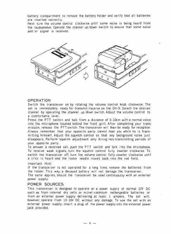
battery compartment to remove the battery holder and verify that ail batteries are inserted correctly.Next turn the volume control clockwise unti! some noise is being heard from the loudspeaker. Operate the ch'annel up/down switch to ensure that some noise and/or signal is received.
OPERATIONSwitch the transceiver on by rotating the volume control knob clockwise. The set is immediately ready for transmit/reçeive on the CH-9. Select the desired channel by operating the channel up/down switch. Adjust the volume control to a comfortable level.Press the PTT switch and talk from a distance of 5-10cm w itha normal voice into the microphone located befjind the front g rill. A fter completing your trans- missJon, release the PTT switch. The transceiver w ill then be ready for réception. Always remember that your opposite party cannot hear you while he is trans- m itting himself. Adjust the squelch control so that any background noise just disappears. Perform squelch adjustment only during non-transmitting periods of your opposite party.To answer a received call, push the PTT switch and talk into the microphone. To receive weak signais, turn the squelch control fu lly counter clockwise. To switch the transceiver off, turn the volume control fu lly counter clockwise untii a click is heard and the meter needie moves back into the red field.Important Hint:If the transceiver is not operated for a long time, remove the batteries from the holder. This way, a decayed battery w iii not damage the transceiver.The same applies, should the transceiver be used continuously with an external power supply.
POWER SOURCESThis transceiver is designed to operate on a power supply of normal 12V DC such as from internal dry cells or nickel-cadmium rechargeable batteries or from an external power suppiy delivering at least 1 ampere. The set will, however, operate from 10-16V DC without any damage. To use the set with an external power supply, insert a plug of the power supply into the external power jack provided.
— 4 —

BATTERY CHARGER STANDOn the bottom of the cabinet, there are battery charger contacts provided. Consuit a SOMMERKAMP dealer for the proper charger stand.When you use rechargeable batteries, charge them either by plugging an ap- propriate battery charger into the charger jack located on the le ft hand side of the set or by inserting the transceiver into a battery charger stand. Charge the batteries for about 14 hours. It is not possible to operate the set during battery charging.
To connect the set to a 12V automobile battery, use a IA fuse in sériés with the positive wire. Solder the positive wire to the center of the external power pług and the negative wire to its fin.
For private listening, plug an earphone piece into the earphone jack provided. The internal speaker will then disconnect automatically.
To operate the transceiver on a 50 ohm external antenna, connect it to EXT. ANT jack provided on the top.
CHANNEL 9It is so designed that the transceiver is switched on always with the channel 9 which is the Emergency Channel.
LIST OF CHANNEL FREQUENCY
CH. FREQ. CH. FREQ. CH. FREQ. CH. FREQ.
1 26,965 7 27,035 13 27,115 19 27,185
2 26,975 ■ 8 27,055 14 27,125 20 27,205
3 26,985 9 27,065 15 27,135 21 27,215
4 27,005 10 27,075 16 27,155 22 27,225
5 27,015 11 27,085 17 27,165
6 27,025 12 27,105 18 27,175
— 5 —

MIC JACK
The 8 -pin DIN standard Mic jack has the following internal connections:1. Microphone input (Z600-10K ohm) 6. +12V for VOX unit etc.2. Transmit/Receive switching 7. AF out for sélective cal 1.3. Ground(SP) 8- SQUELCH4. Audio output. (Z8-10K ohm) Case = ground5. Internai speaker.
Always operate the transceiver with the microphone plug inserted in the microphone jack, or with the following external connections:
1. Microphone with VOX. 5. External microphone/Speaker with PTT.
I &° 5 “ 4 °
0 3 0 8 1
. i 6 0 0 - ЮК ohm Microphone
2. Headset or Telephoneset w ith PTT.
V 7 - 2 4 °1—^ 0 3 0 8 10-1
7 6,
= d )600 ~ 10K ohm Microphone
3. External microphone
Microphone 600 - 10K ohm
Speaker/Mic
6. Internai connection
7. Internai connection with SP. sélection switch SP. sélection switch
MIC. /Shortening Plug
i IT/R Switch
— 6 —
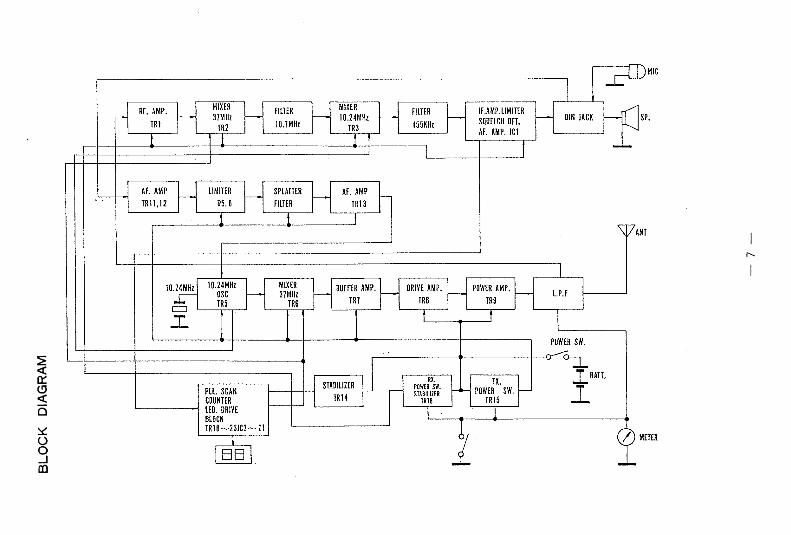
BLO
CK
D
IAG
RAM


PRINTED CIRCUIT BOARD PARTS LAYOUT (MAIN)
Z WOK ' 390K33ISK
dT m so Ч00К ,m .n —IW“ W«CK! ‘01 /u J2K \ 1HP i f U i * S0/000
12?_rv\.
,sy K Щ ‘ % J *тг iscwsmf ctit тки /к ł -üri < j ‘ T » Г 1" т е *
■ - Y & 4 t «— W Л £'Г (40
TJMm / hk1 C41
HO*"“ I ß
т , ' ,к си а ■«т к т !ш \" Va “ ’ __*— T,,v" " у / , m <ś _iQ— Чита да» южТ§"\;С’ У -
. 4■ ■ —Ш(-
«< ж
V * » ‘4 f
—W- ^да / ïWiraoim r N , MSL У T-T^iжг 2,als , Ш 1 t 5Si 3f
'1>TS 'H!— ess sp —il—CSiJP
îJ* cm, ms iЖ
nи истцам s i t \~7*IÎO й 'р rx/i y ' i,W
\ j K ISCIUim f ' t u 2-7K_ , Pt] Ш4002 C J~kh ] -0H
T 006, i £—^ s 1 007 /_Д ® да2SAS4S<V-̂D/2* * . 3*£A -~ £ " 4 j£ шS g / i«r/w/re -?7 V я VV/Sf i 4 lit
Ш1 ^ * « Й Т * î - i " Â 'Ж , SS. S i ~ I s З Г -и - «a, ;U î «■" i isg " « 4 p Hf- ^з. Г>2- W7 __........ S lS l/ Й
S T ,
;. Cil >022 ,.-.J-S fc,g-TS SL'
У A4UQK >2» 3 - T- f/»#ś. /tf/WT*■ ^ /л c
L6
IIest >ou
'КD*t v (0)
m tt23
LU
OS ‘01-V- '«г л —Ił—-
а я 4 «p f ^ ' ,я
C/> '0?23 « : л 2»яг ui
, 5 ^ “oiJ2K dation cihKfnpM / f 7......... ..... II— -Vn_
l e s , * *----- pg 2SC20S6
«* % * = % % ■ ■ ш 1 “T:----i 2 ^
r1 ISISSS
m
U LJ ■iz : •W 2r~
3SK40 |' 100K
J . ?± JS LIT
1 1 ' oT Î5C7i WP-Hh
X » Ш **0ГАУ
#014///4002
— 10
TAT8
Ш0Р

SCH
EM
ATI
C
DIA
GR
AM

PRINTED CIRCUIT BOARD PARTS LAYOUT (SUB)
5 ^ Y Y ^ V:
I ^ H ?S .W 7X24 2SCJ646(B) ^
“<\|\5\3\s\§\^ / \ж-и-~ ' L i - L v № OKO/5/55Sc#W2rt.X ■
DS! JS 1555щ § ÿ ÿ v si.j
I r e , ICO TCS022BF3
* Â ^ , Л ...... /
Л 34 470К
I
U1V Ul?. - P r jA " , R i Ü t t O K 049 Z j U 2 ;
; >S и 2ICH ТС45ЮВР
J/i J 1
_pjlfU* mis
c'fe7*JioK \_m
§1§T 11
9 ... . /6
K t 7CS022BP
1
o u J ? ; /s im ,mss
Mf&îs/sis~
—t4l— 04b(SISSS
ftyr -V rD 47w istsss
lSI555çi5fïï b(r)2
/6ICIO TC45IÛBP' _____
*V
JI29- • Ш -V y ,^ » Л
W7 ( u f 330K V
Ж”юй tftf« cmкт X â
Я -.P .fL - 31к m s f
i -, j ' ■ г
(bt ą HCI4572UB
i
031— И - ISI5SS
.—i[— HMls- D,& —1U(~, W . W > r f ! l * * » ) Р « £ Т Г Ш m -
f f l f /(« * W ? , /Ш 7 31K X , / * 1 д цq p «O - i t нь ------ Ufe
- .& Vй* . cm-a шГК17П0рХ ',±
H h*C/54 >0033 \RU\ \330K
■^.т г^ 27K
5' i i lê ^ испит ,ST§ 1g “ à XJ
- 012 rm
ŚJ?iS
TS, «jfÜ p u w >о /
iW 1р*3'Ч£//г CS l/Щ м ш / Ф iiî iï ! / st
U S
R14Q 33K
KIJIj m X окно UK U m-Ot
m a if
л
с / _s*j T. W |\ÿC/3S...0I
‘ « J . * :- « a т о л Ш / /й7 sCUO X «Й •A4' " ‘ "‘ -L i l
w T , / w T « 7 T > s > V ™ ^. X m iookZf- t 5|Л V «51
Ъ : грЬ " ^ # ° * ъ ' с m t eР -Щ о M siss s ^ m ' ■ & hiss
ш шL32
32? \ С 1$Ш23(0)
^ i?XIшТш
" А
i
Ж СМ , Ь2Р
,£7№220922(0)
i V * ^ 560’Ш Ш Г Ttù, 2Ш0№)
тгр ̂ .JŁ
2112 МОК IC4 ТС40ИВР
Ш I2K5 g ' P ; '* v ^ s « g „
S —i— 020ISISSS
Жcm m m Лсю •пт)
— 11

WIRING LAYOUT
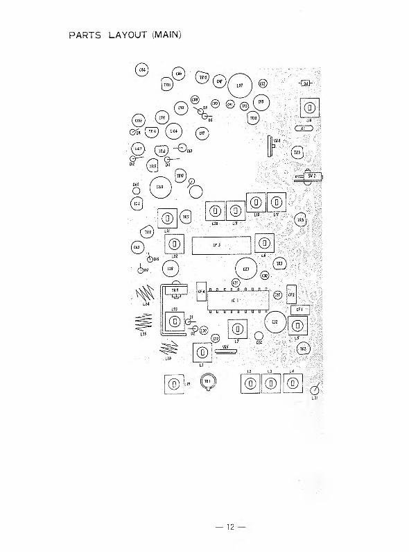
PARTS LAYOUT (MAIN)
12____Ü____ L£
® K r e i l )1.27 V ® ' / ® ® ®
L3I
— 12

PARTS LAYOUT (SUB)
m a u ' u u и с— fe /Q © - - 1
; ust - O w7 ^ ù~О ®045 • ©м/П П П П П Г
/Ć5": А
иг -©О ---------© ря
Л II П П П ..Д и п
042
fc__/ иа>. ■- \ — ищ
п П ..Л П . Д ..Д ...Пч Ш ч • • \^ " \lg. 1С1°
U : И""!]" D"""D и u и
=ал
_ 3
1 • Т Т > \- ешь. ■- -,- - ■ :\2 Л -(Ti »и.... ' 1 _.jl .Л, Q 0 4 ,
ш
ICI \‘ и u 1) и и ' U "U ‘ U'
0 ^ O ^ f \— ~Оол f".
п п п п п п п п
S).Ъ_ ii #<Г/fi Шъ i ■ »«#
Т Г Г Г U и I 038 -------.0
} '&
SJ?57 û
, \ 1 -»V • - •Л Ь » ь %
- рÄ L , „ss«*e»eas
» j f I
Ü и ? Ü
-; V-ж Л г е
; ' 9 0л
tai
^n n rü n T rV— ~ ~ Q dss
~ч ' ;i;'■w V 4 .Q i
I . h h j ; v « 0 \ ' \ 7 Ш 0 .;'
., ^ ,..,п д : a П - . .П n : .n. ..n п п п : п ,~ I$ ä*\ si ы в-.* ш \ \ w f .? *
IC 3 ■■
u, u u u и и u ,u . u u u u , .Ï3 ) Q 018 1 :
«* ,
»É *У Æ if  p J J MW -CMI i
- LeИ ©m :0
ч";С:: L34
\ ^Cf23:;._ CI22
0 ;• D1F - -
CI 62
1 &
1/ ^ \ й ; .(ти
7«':'’ ;■■ ъ © А ф
Ш - :? « © > О о и 7 _ ■
' ' D2? - - У
, i’ j ÿ r i i o ï ï '
"tiw?;п п р и..л л
r 5 ^ i c 4 ‘" -V g p
U U ÏT U' U U" u
; O c i is O c
|032
фоз4 ■
J i:-132
15 —
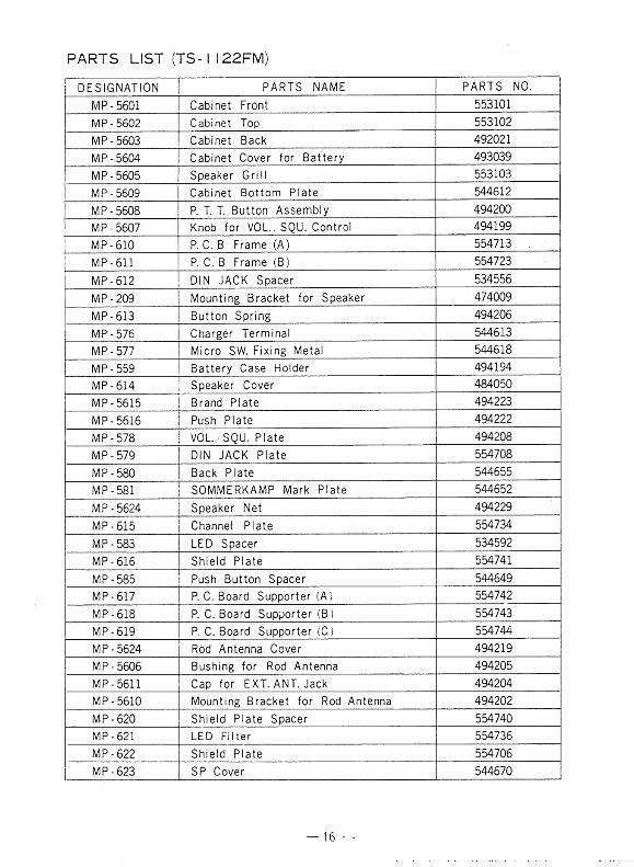
PARTS LIST (TS -I I22FM )
DESIGNATION PARTS NAME PARTS NO.MP-5601 Cabinet Front 553101MP-5602 Cabinet Top 553102MP-5603 Cabinet Back 492021MP-5604 Cabinet Cover for Battery 493039MP-5605 Speaker Grill 553103MP-5609 Cabinet Bottom Plate 544612MP-5608 P. T. T. Button Assembly 494200MP-5607 Knob for VOL, SQU. Control 494199MP-610 P. O.JB Frame (A) 554713MP-611 P. С. В Frame (B) 554723
MP-612 DIN JACK Spacer 534556MP-209 Mounting Bracket for Speaker 474009MP-613 Button Spring 494206MP-576 Charger Terminal 544613MP-577 Micro SW. Fixing Metal 544618MP-559 Battery Case Holder 494194MP-614 Speaker Cover 484050MP - 5615 Brand Plate 494223MP-5616 Push Plate 494222MP-578 VOL./SQU. Plate 494208MP-579 DIN JACK Plate 554708MP-580 Back Plate 544655MP-581 SOMMERKAMP Mark Plate 544652MP-5624 Speaker Net 494229MP-615 Channel Plate 554734MP-583 LED Spacer 534592MP-616 Shield Plate 554741MP-585 Push Button Spacer 544649MP-617 P. C. Board Supporter (A) 554742MP-618 P. C. Board Supporter (В ) 554743MP-619 P. C. Board Supporter (C) 554744MP-5624 Rod Antenna Cover 494219MP-5606 Bushing for Rod Antenna 494205MP-5611 Cap for EXT. ANT. Jack 494204MP-5610 Mounting Bracket for Rod Antenna 494202MP-620 Shield Plate Spacer 554740MP - 621 LED Filter 554736MP-622 Shield Plate 554706MP-623 SP Cover 544670

PARTS LIST (TS- I 122 FM)
DESIGNATION PARTS NAME PARTS N0.TRI FET ' 3SK40 (L)
TR2,3,5,6,7,17,18,19,21 Transistor 2SC1923 (0)TR8 Transistor 2SC2086TR9 Transistor 2SC1957TRIO, 14, 16 Transistor 2SC1741 (Q)TR11, 12, 13, 22 Transistor 2SC1815 (GR)TR15 Transistor 2SA854 (Q)TR20 FET 2SK19 (GR)TR23 Transistor 2SA1015 (Y)TR24 Transistor 2SC1646 (B)ICI IC SL16640CIC2 IC TA78L010PIC3 IC ' >PD2810CIC4, 7 IC TC4Û11BPIC5 IC TC4081BPIC6 IC MC14572UBIC8, 9 IC TC5022BPIC10, 11 IC TC4510BPDl,2,5,6,9,10,11,19, 20.22—57. 58. 59 Silicon Diode IS1555D13, 14, 60 Silicon Diode IN4002D16 Germanium Diode IN60D4, 15 Variable Capacitance Diode ISV50D7, 12, 21 Zener Diode WZ072D8 Zener Diode WZ 062D17, 18 RF Diode M1301LED1, 2 LEDCF1, 2 Ceramic Filter SFE10.7CF3 Ceramic Filter CFR455HCF4 Ceramic Filter SFU455B
•XI X’tal 10.24 MHzX2 X’tal 36.29 MHz 30/UX3 X’tal 10.24 MHz 30/UTC1 Trimmer Condenser CV05A060TC2 Trimmer Condenser CV05E3001M Meter 500,uAMIC Condenser Mic WM065WFB Ferrite Beads T314 OP3.5-3HJ1 Mic Jack DIN TypeJ2 EXT. ANT. Jack RCA Type
— 17 —
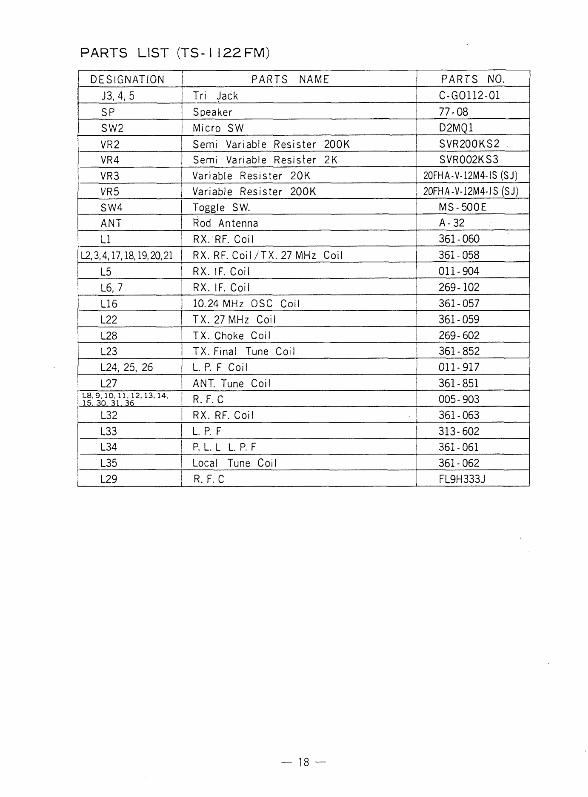
PARTS LIST (T S -I l 2 2 FM)
DESIGNATION PARTS NAME PARTS N0.J3, 4, 5 Tri Jack C-G0112-01SP Speaker 77-08SW2 Micro SW D2MQ1VR2 Semi Variable Résister 200K SVR200KS2 .VR4 Semi Variable Résister 2K SVR002KS3VR3 Variable Résister 20K 20FHA-V-12M4-IS (SJ)VR5 Variable Resist er 200K 20FHA-V-12M4-IS (SJ)SW4 Toggle SW. MS-500EANT Rod Antenna A- 32LI RX. RF. Coil 361-060
L2,3,4,17,18,19,20,21 RX. RF.CoM/TX.27MHz Coil 361-058L5 RX. IF. Coil 011-904L6, 7 RX. IF. Coil 269-102L16 10.24 MHz OSC Coil 361-057L22 TX. 27 MHz Coil 361-059L28 TX. Choke Coil 269-602L23 TX. Final Tune Coil 361-852L24, 25, 26 L. P. F Coil 011-917L27 ANT. Tune Coil 361-851
L8.9,10.11.12.13.14. 15. ЗП 31. 35 R. F. C 005-903L32 RX. RF. Coil 361-063L33 L. P. F 313-602L34 P. L. L L. P. F 361-061L35 Local Tune Coil 361 - 062L29 R. F. C FL9H333J
18 —
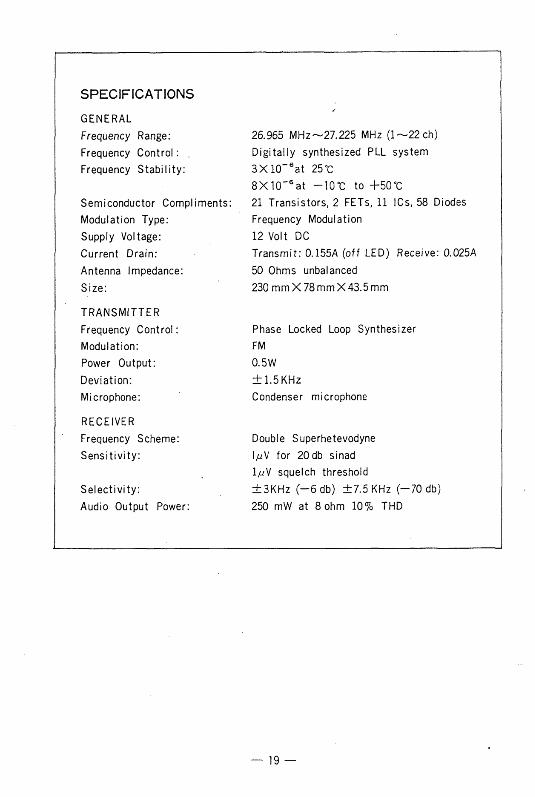
SPECIFICATIONS
GENERAL '
Frequency Range: 26.965 MHz—27.225 MHz (1—22 ch)Frequency Control : . D igitally synthesized PLL systemFrequency Stability: 3 X 1 0 '6at 25 °C
Semiconductor Compliments:8 X 1СГ6at - 1 0 “C to + 5 0 °C 21 Transistors, 2 FETs, 11 ICs, 58 Diodes
Modulation Type: Frequency ModulationSupply Voltage: 12 Volt DCCurrent Drain: Transmit: 0.155A (off LED) Receive: 0.025AAntenna Impédance: 50 Ohms unbalancedSize: 230 mm X 78 mm X 43.5 mm
TRANSMUTERFrequency Control : Phase Locked Loop SynthesizerModulation: FMPower Output: 0.5WDeviation: ±1.5KHzMicrophone: Condenser microphone
RECEIVERFrequency Scheme: Double SuperhetevodyneSensitivity: 1/zV for 20 db sinad
1 juV squelch thresholdSelectivity: ±3KHz (—6 db) ±7 .5 KHz (-7 0 db)Audio Output Power: 250 mW at 8 ohm 10% THD
— 19 —

S O I V I Î V 1 E R K A I V 1 P E L E C T R O I U I C S A S
СН-6ЭОЗ LUGANO, R O. BOX 17B SWITZERLANDTEL.C911B88543 TELEX 79314