CITATION MUSTANG OPERATING MANUAL … to flow. Passenger masks have no flow indicator. CONTROLS AND...
12
GENERAL The oxygen system includes the crew and pas- senger distribution systems (Figure 17-1). Oxygen is available to the crew at all times and is available to the passengers either automat- ically above a cabin altitude of approximately 14,800 feet, or manually at any altitude by the oxygen control valve. The squat switches provide signals to various aircraft systems, controls and indications to ad- just them for different operation, depending on whether the aircraft is in flight or on the ground. The specific role of the squat switch in each aircraft system is described in detail in that system chapter of this manual. 510OM-00 17-1 CHAPTER 17 MISCELLANEOUS SYSTEMS INTRODUCTION This chapter covers the oxygen system and squat switch (weight-on-wheels sensing) sys- tems on the Citation Mustang. Oxygen is available to the crew and passengers during pressurization system malfunctions or when required. One squat switch on each land- ing gear indicates when weight is on the wheel. The squat switches provide signals to various aircraft systems. CITATION MUSTANG OPERATING MANUAL
Transcript of CITATION MUSTANG OPERATING MANUAL … to flow. Passenger masks have no flow indicator. CONTROLS AND...

GENERALThe oxygen system includes the crew and pas-senger distribution systems (Figure 17-1).Oxygen is available to the crew at all times andis available to the passengers either automat-ically above a cabin altitude of approximately14,800 feet, or manually at any altitude bythe oxygen control valve.
The squat switches provide signals to variousaircraft systems, controls and indications to ad-just them for different operation, dependingon whether the aircraft is in flight or on theground. The specific role of the squat switchin each aircraft system is described in detailin that system chapter of this manual.
510OM-00 17-1
CHAPTER 17MISCELLANEOUS SYSTEMS
INTRODUCTIONThis chapter covers the oxygen system and squat switch (weight-on-wheels sensing) sys-tems on the Citation Mustang. Oxygen is available to the crew and passengers duringpressurization system malfunctions or when required. One squat switch on each land-ing gear indicates when weight is on the wheel. The squat switches provide signals tovarious aircraft systems.
CITATION MUSTANG OPERATING MANUAL

510OM-0017-2
CITATION MUSTANG OPERATING MANUAL
OX
YG
EN
BO
TT
LE
LP
RH
MU
LTI-
FU
NC
TIO
NP
CB
WIT
HT
RA
NS
DU
CE
R
LH M
ULT
I-F
UN
CT
ION
PC
B W
ITH
TR
AN
SD
UC
ER
PIL
OT
OX
YG
EN
MA
SK
CO
PIL
OT
OX
YG
EN
MA
SK
NO
RM
AL
(SO
LEN
OID
VA
LVE
NO
RM
ALL
Y C
LOS
ED
)
OX
YG
EN
CU
TOF
F V
ALV
E
OX
YG
EN
BLO
WO
UT
DIS
CF
ILL
PO
RT
LOW
OX
YG
EN
PR
ES
SU
RE
SW
ITC
H(O
XY
GE
N O
FF
- C
AS
ME
SS
AG
E)
OX
YG
EN
CO
NT
RO
LV
ALV
E
OX
YG
EN
SU
PP
LYH
AN
DLE
RE
GU
LATO
R
CH
EC
KV
ALV
E
CA
BIN
DR
OP
BO
X A
SS
EM
BLY
(DO
UB
LE M
AS
K)
CA
BIN
DR
OP
BO
X A
SS
EM
BLY
(SIN
GLE
MA
SK
)
OX
YG
EN
CO
NT
RO
LV
ALV
E S
ELE
CTO
R
CR
EW
ON
LY
DR
OP
MA
SK
BO
TT
LE P
RE
SS
UR
E
LE
GE
ND
RE
GU
LAT
ED
CR
EW
OX
YG
EN
(AV
AIL
AB
LE T
O C
RE
W A
T A
LL T
IME
S)
RE
GU
LAT
ED
PA
SS
EN
GE
R O
XY
GE
N(C
ON
TR
OLL
ED
BY
OX
YG
EN
CO
NT
RO
L V
ALV
E)
OX
YG
EN
GA
UG
E
Fig
ure
17-
1.O
xyg
en S
yste
m S
chem
atic
OXYGEN SYSTEM
DESCRIPTIONThe Mustang oxygen system is primarily foremergency use, but also allows limited-dura-tion nonemergency use. It provides breath-able low-pressure oxygen (at approximately70 psi) to crew and passengers through indi-vidual oxygen masks.
The system uses a single bottle of compressedoxygen to supply both crew masks and passen-ger masks. A regulator controls overall systempressure, and a shutoff valve (controlled by anoxygen supply valve labeled OXYGEN SUPPLYin the cockpit) enables or disables the system.Another cockpit control labeled OXYGENCONTROL VALVE selects distribution modes.
An oxygen gauge indicates the pressure (and in-directly, volume) of oxygen in the bottle. A crewalerting system (CAS) message indicates wheninsufficient oxygen is available. If oxygen sup-ply is shut off or if pressure in the system is toolow, an amber OXYGEN OFF message appears.
Individual controls on crew masks adjust theiroxygen flow.
COMPONENTSThe system includes:
• Oxygen bottle (with integral shutoffvalve and pressure regulator)
• Oxygen masks (crew and passenger)
• Oxygen control valve
Oxygen BottleA single bottle holds all compressed oxygenfor the system. It is on the right side of the nosestorage compartment and has a 623-liter (22-cubic-feet) useable capacity with 1,133-liter(40-cubic-feet) option. Oxygen is stored inthe bottle at a pressure between 1,600 and1,800 psig.
A shutoff valve and pressure regulator on thebottle control the flow of oxygen to the dis-tribution system (Figure 17-1). The regulatorreduces oxygen system pressure to 70 psidownstream of the bottle. The shutoff valve onthe bottle is normally open in flight. It is me-chanically controlled in the cockpit by theOXYGEN SUPPLY control knob.
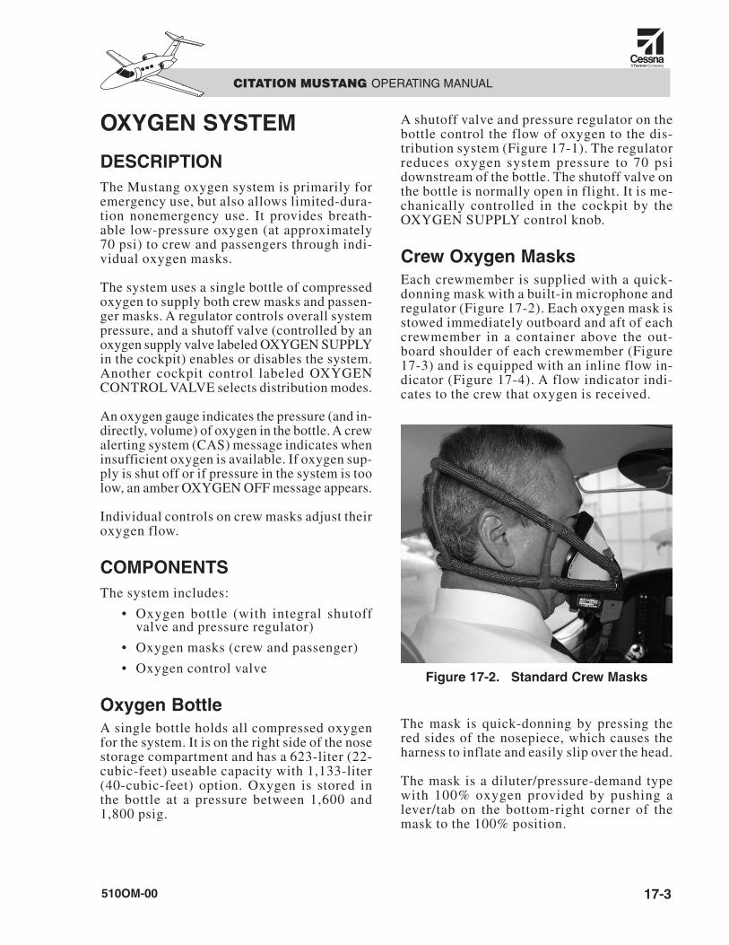
Crew Oxygen MasksEach crewmember is supplied with a quick-donning mask with a built-in microphone andregulator (Figure 17-2). Each oxygen mask isstowed immediately outboard and aft of eachcrewmember in a container above the out-board shoulder of each crewmember (Figure17-3) and is equipped with an inline flow in-dicator (Figure 17-4). A flow indicator indi-cates to the crew that oxygen is received.
The mask is quick-donning by pressing thered sides of the nosepiece, which causes theharness to inflate and easily slip over the head.
The mask is a diluter/pressure-demand typewith 100% oxygen provided by pushing alever/tab on the bottom-right corner of themask to the 100% position.
510OM-00 17-3
CITATION MUSTANG OPERATING MANUAL
Figure 17-2. Standard Crew Masks

To qualify as a quick-donning mask, the crewoxygen mask must be properly stowed in thereceptacle behind, above, and outboard ofeach crewmember on the forward cabin di-vider, and must be set to 100%.
NOTEHeadsets, eyeglasses, or hats worn bythe crew wil l interfere with thequick-donning capability of the oxy-gen masks.
The crew masks plug into OXYGEN MASKreceptacles on the pilot and copilot side con-soles (Figure 17-5). The mask oxygen lineplugs into the large valve port, and the maskmicrophone plugs into the MIC jack, both ofwhich are under the OXYGEN MASK sec-tion of the console. Ensure both plugs are fullyinserted before flight.
If the aircraft is to be parked outside and thetemperature is colder than 0°C, the masks mustbe removed from the aircraft and kept warm.
510OM-0017-4
CITATION MUSTANG OPERATING MANUAL
Figure 17-3. Crew Oxygen Mask,Stowed (Pilot Side)
Figure 17-4. Flow Indicator
PILOT CONSOLE
COPILOT CONSOLE
Figure 17-5. Pilot and Copilot Consoles
510OM-00 17-5
CITATION MUSTANG OPERATING MANUAL
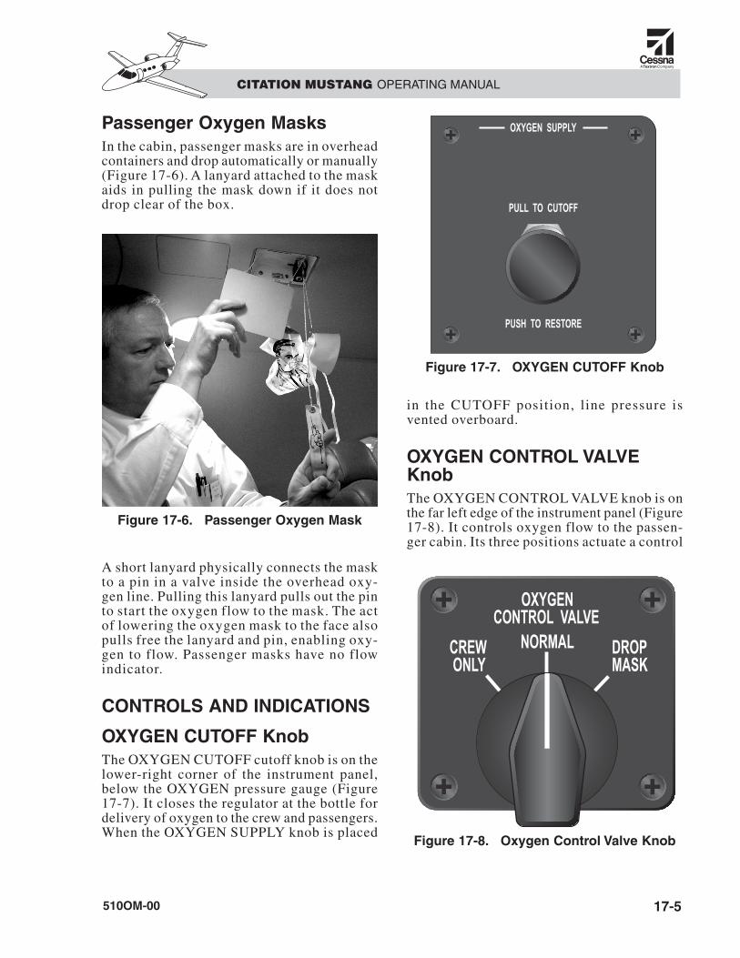
Passenger Oxygen MasksIn the cabin, passenger masks are in overheadcontainers and drop automatically or manually(Figure 17-6). A lanyard attached to the maskaids in pulling the mask down if it does notdrop clear of the box.
A short lanyard physically connects the maskto a pin in a valve inside the overhead oxy-gen line. Pulling this lanyard pulls out the pinto start the oxygen flow to the mask. The actof lowering the oxygen mask to the face alsopulls free the lanyard and pin, enabling oxy-gen to flow. Passenger masks have no flowindicator.
CONTROLS AND INDICATIONS
OXYGEN CUTOFF KnobThe OXYGEN CUTOFF cutoff knob is on thelower-right corner of the instrument panel,below the OXYGEN pressure gauge (Figure17-7). It closes the regulator at the bottle fordelivery of oxygen to the crew and passengers.When the OXYGEN SUPPLY knob is placed
in the CUTOFF position, line pressure isvented overboard.
OXYGEN CONTROL VALVEKnobThe OXYGEN CONTROL VALVE knob is onthe far left edge of the instrument panel (Figure17-8). It controls oxygen flow to the passen-ger cabin. Its three positions actuate a control
Figure 17-7. OXYGEN CUTOFF Knob
Figure 17-8. Oxygen Control Valve Knob
Figure 17-6. Passenger Oxygen Mask
valve for passenger oxygen distribution as de-sired. The knob positions are:
• CREW ONLY
• NORMAL
• DROP MASK
CREW ONLY ModeWhen the control knob of the oxygen controlvalve is placed in the CREW ONLY position,oxygen is not available to the passengers. In thisposition, oxygen is only available to the crew.
After donning the mask, the crew must set thelever under each mask to NORMAL or 100%.For pressure breathing, rotate the mask emer-gency select knob to EMERGENCY.
NOTEOxygen masks are certified to 40,000feet cabin altitude for the crew only.The CREW ONLY mode operateswith or without DC power.
NORMAL ModeWhen the oxygen system is enabled, if theOXYGEN CONTROL VALVE knob is selectedto the NORMAL position (see Figure 17-8),passenger oxygen masks automatically dropdown from the cabin ceiling anytime cabinpressure altitude is greater than 14,800 feet.
Normally, the pressurization system main-tains an 8,000-foot cabin altitude up to themaximum certified altitude. However, if cabinaltitude exceeds approximately 14,800 feet, acabin-altitude sensor energizes the passengeroxygen solenoid valve open. Oxygen flowsinto the passenger distribution system and re-leases latches on the mask compartment doors.This allows the doors to open and the masksto fall out.
After restoration of the cabin pressure to nor-mal values, the solenoid valve deenergizesclosed at approximately 11,500 feet cabin al-titude, shutting off oxygen flow to the passen-gers. The pilot can bypass the solenoid valve
by selecting the OXYGEN CONTROL VALVEknob to DROP MASK.
DROP MASK ModeThe pilot can supply oxygen to the passengersat any cabin altitude by placing the OXYGENCONTROL VALVE selector to the DROPMASK position (see Figure 17-8). When thisposition is selected, all masks in the cabin toimmediately drop from the cabin overhead.This mode operates with or without DC power.When oxygen flow to passengers is not desired,shut off oxygen flow to passenger masks byselecting the OXYGEN CONTROL VALVEknob to the CREW ONLY position at any time,or the NORM position when below 11,500feet cabin altitude.
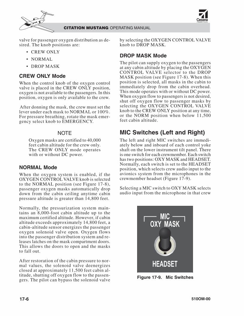
MIC Switches (Left and Right)The left and right MIC switches are immedi-ately below and inboard of each control yokeshaft on the lower instrument tilt panel. Thereis one switch for each crewmember. Each switchhas two positions: OXY MASK and HEADSET.Normally, each switch is set to the HEADSETposition, which selects crew audio input to theavionics system from the microphones in thecrewmember headset (Figure 17-9).
Selecting a MIC switch to OXY MASK selectsaudio input from the microphone in that crew
510OM-0017-6
CITATION MUSTANG OPERATING MANUAL
Figure 17-9. Mic Switches

oxygen mask, and disables audio input fromthat crewmember headset microphone.
Depressing the microphone button on the re-spective control wheel allows the crewmem-ber to transmit through the headset microphoneor through the oxygen mask microphone, as se-lected by the respective MIC switch.
When the switch is in the OXY MASK posi-tion, the cockpit speaker turns on and cannotbe turned off using the audio panel button.
OXY CONTROL Circuit BreakerThe OXY CONTROL circuit breaker in the EN-VIRO section of the pilot CB panel protects thepassenger oxygen solenoid valve. Pulling thiscircuit breaker disables the spring-loaded sole-noid, which closes the valve.
OXYGEN Pressure GaugeThe OXYGEN pressure gauge (Figure 17-10)is on the right side of the copilot instrumentpanel, below and to the right of the copilot pri-mary flight display (PFD), and above the OXY-
GEN CUTOFF knob (see Figure 17-7). Thegauge illuminates internally.
The range markings are as follows:
• Yellow arc................................. 0–400 psi
• Red line................................... 2,000 psi
Service anytime gauge indicates insufficientvolume. Refer to the Airplane Flight Manual(AFM); normal indication is between 1,600 and1,800 psig.
OXYGEN OFF MessageThe amber OXYGEN OFF message appearswhen the oxygen system pressure-sensor switchdetects system pressure below approximately45–50 psig. The message extinguishes if sys-tem pressure rises above 50–55 psig. This mes-sage also displays when the OXYGEN SUPPLYknob is in the PULL TO CUTOFF position.
Overboard Discharge IndicatorA green overboard discharge indicator (disc)is on the right side of the nose section di-rectly below the nose access door (Figure 17-11). If the disc is ruptured, the oxygen bottle
510OM-00 17-7
CITATION MUSTANG OPERATING MANUAL
Figure 17-10. Oxygen Pressure Gauge Figure 17-11. Overboard DischargeIndicator
510OM-0017-8
CITATION MUSTANG OPERATING MANUAL
has experienced overpressure and is nowempty. If the disc ruptures, perform mainte-nance before flight.
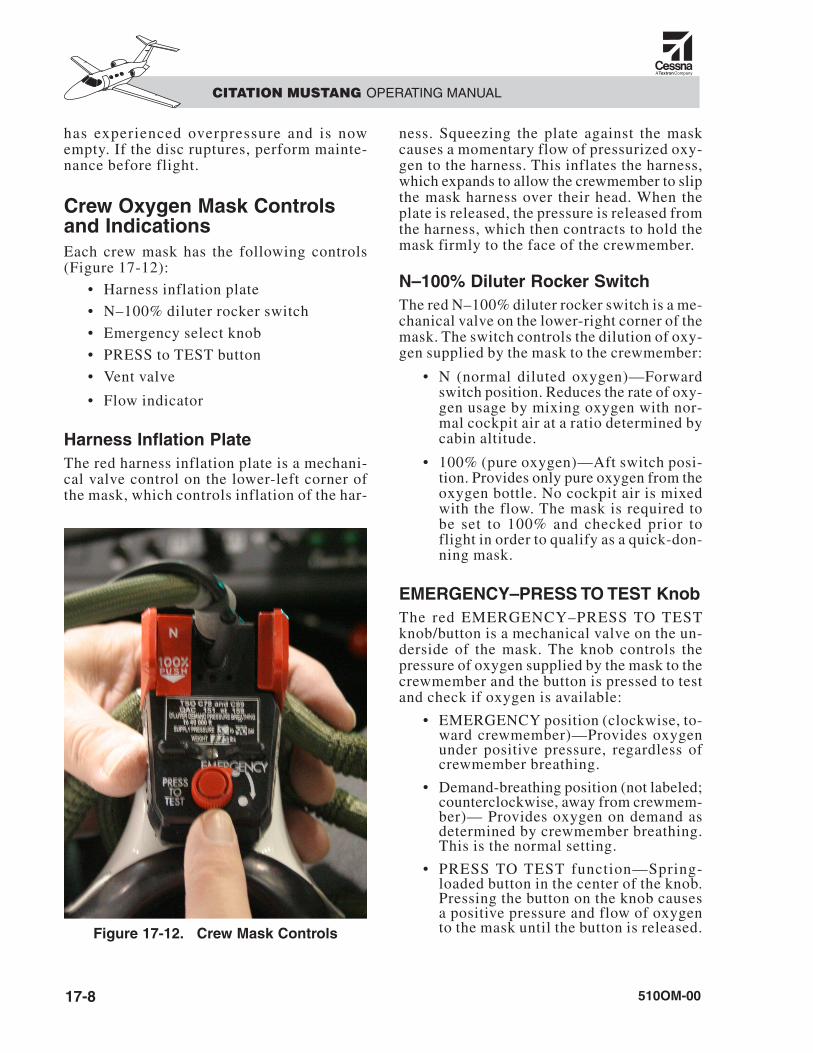
Crew Oxygen Mask Controlsand IndicationsEach crew mask has the following controls(Figure 17-12):
• Harness inflation plate
• N–100% diluter rocker switch
• Emergency select knob
• PRESS to TEST button
• Vent valve
• Flow indicator
Harness Inflation PlateThe red harness inflation plate is a mechani-cal valve control on the lower-left corner ofthe mask, which controls inflation of the har-
ness. Squeezing the plate against the maskcauses a momentary flow of pressurized oxy-gen to the harness. This inflates the harness,which expands to allow the crewmember to slipthe mask harness over their head. When theplate is released, the pressure is released fromthe harness, which then contracts to hold themask firmly to the face of the crewmember.
N–100% Diluter Rocker SwitchThe red N–100% diluter rocker switch is a me-chanical valve on the lower-right corner of themask. The switch controls the dilution of oxy-gen supplied by the mask to the crewmember:
• N (normal diluted oxygen)—Forwardswitch position. Reduces the rate of oxy-gen usage by mixing oxygen with nor-mal cockpit air at a ratio determined bycabin altitude.
• 100% (pure oxygen)—Aft switch posi-tion. Provides only pure oxygen from theoxygen bottle. No cockpit air is mixedwith the flow. The mask is required tobe set to 100% and checked prior toflight in order to qualify as a quick-don-ning mask.
EMERGENCY–PRESS TO TEST KnobThe red EMERGENCY–PRESS TO TESTknob/button is a mechanical valve on the un-derside of the mask. The knob controls thepressure of oxygen supplied by the mask to thecrewmember and the button is pressed to testand check if oxygen is available:
• EMERGENCY position (clockwise, to-ward crewmember)—Provides oxygenunder positive pressure, regardless ofcrewmember breathing.
• Demand-breathing position (not labeled;counterclockwise, away from crewmem-ber)— Provides oxygen on demand asdetermined by crewmember breathing.This is the normal setting.
• PRESS TO TEST function—Spring-loaded button in the center of the knob.Pressing the button on the knob causesa positive pressure and flow of oxygento the mask until the button is released.Figure 17-12. Crew Mask Controls

Vent ValveWhen smoke goggles are worn, they fit overthe vent on the top of the mask nosepiece. Avent valve control on the front of the masknosepiece slides forward to open the vent toallow oxygen to enter and clear the smokegoggles.
NOTEOpen the vent valve only if pressurebreathing (EMERGENCY position)has been selected. If the vent isopened when the mask is in the otherposition (demand breathing), smokemay be drawn into the mask.
Flow IndicatorA flow indicator (slide in the mask hose nearthe connector to the oxygen panel) shows clearwhen oxygen is available to the mask and isflowing. It shows black when there is no flow.
OPERATIONFor specific, current instructions on normal op-erations, refer to the AFM. Where the follow-ing information differs from the AFM, use theAFM information and follow the AFM instruc-tions. The following information is only fortraining and background information.
Strictly obey the procedures for theuse of oxygen equipment. Do notuse oil, grease, or other lubricantsmade from petroleum in the area ofoxygen equipment. This can cause adangerous fire hazard.
PreflightDuring preflight, ensure the OXYGEN SUP-PLY control knob is fully pushed in (forward)to open the shutoff valve on the oxygen bot-tle. Check that proper pressure is indicated onthe OXYGEN gauge. Test each crew mask be-
fore flight using the PRESS TO TEST buttonto be sure that it is receiving oxygen from thesystem. Ensure that oxygen flows into themask and to the pilot under positive pressure.Before takeoff, check that the OXYGEN OFFmessage is not displayed and the OXYGENVALVE is in the NORMAL position. In FlightTo operate the oxygen system, ensure there isadequate pressure in the system as indicatedby these three conditions:
• The OXYGEN gauge indicates adequatesupply (refer to AFM)
• The OXYGEN SUPPLY knob is pushedin (forward) fully
• The OXYGEN OFF message does notappear
When those conditions are met, the oxygensystem can be operated in one of three modesas selected by the pilot using the OXYGENCONTROL VALVE knob.
Crew Oxygen MaskRemove the crew oxygen mask from its con-tainer and squeeze the mask so the harness in-flation plate is pressed against the mask toinflate the harness. Place the harness over thehead and position the mask over the face andnose, then release the harness inflation plate. Theharness contracts to hold the mask in place.
The crewmember is assured that oxygen isbeing received when no restriction to breath-ing is present with the mask donned and thered N–100% diluter rocker switch is set to100% (aft position). If the cabin altitude is ator below 25,000 feet, to conserve oxygen whenusing the mask, the diluter rocker switch maybe set to normal (N).
NOTEOn crew masks, select 100% oxy-gen above 25,000 feet cabin altitude.At cabin altitudes of 25,000 feet andbelow, select normal (N).
WARNING
510OM-00 17-9
CITATION MUSTANG OPERATING MANUAL
510OM-0017-10
CITATION MUSTANG OPERATING MANUAL
For pressure breathing or smoke/fumes pro-tection, rotate the emergency select knob onthe underside of the mask clockwise toward thecrewmember to the EMERGENCY position(see Figure 17-10). This position provides asteady flow of pressurized oxygen to the facecone and the smoke goggles (if installed).
Maintenance ConsiderationsService the oxygen system any time the pres-sure gauge indicates inadequate supply, orwhen the overboard discharge indicator showsan overpressure event has occurred.
If the oxygen bottle depletes to empty or if theoxygen discharge indicator ruptures, the systemmust be purged and the oxygen bottle replacedbefore the next flight. The original oxygen bot-tle must be returned to the supplier for refurbish-ment or replacement before further use.
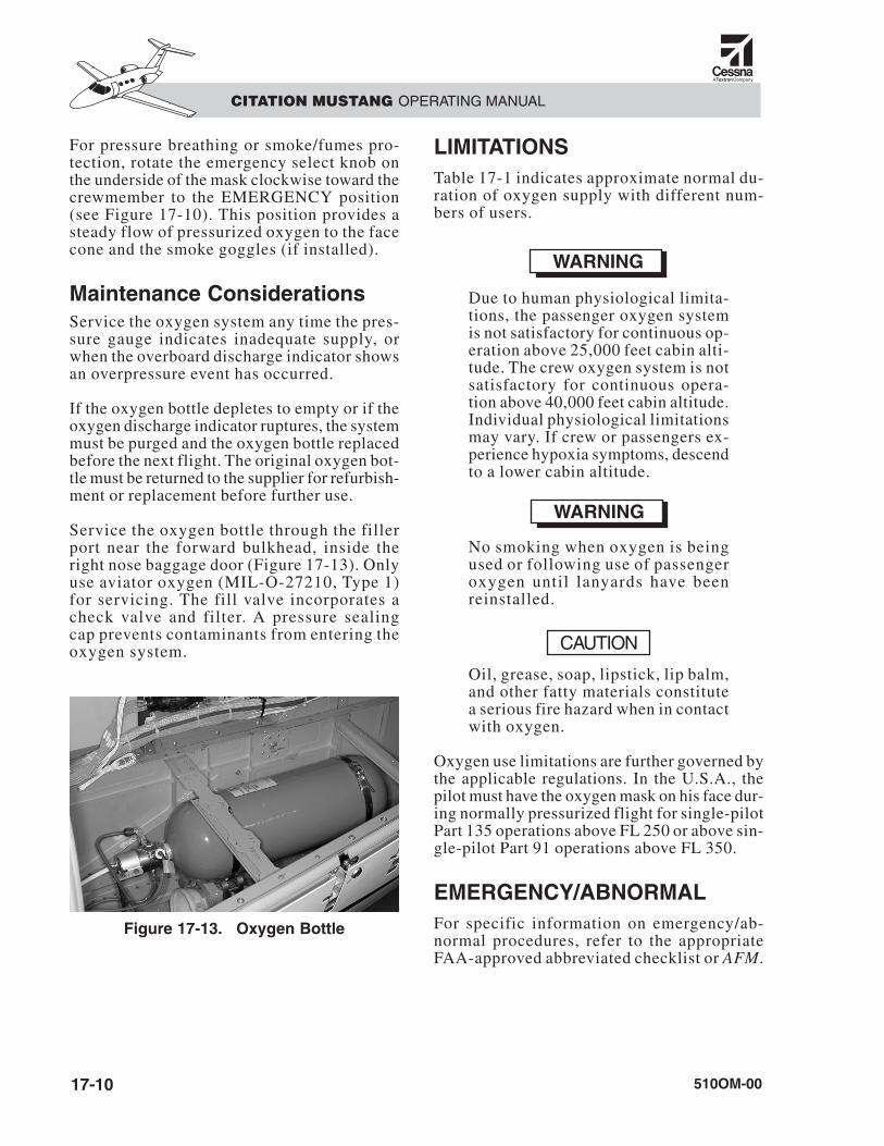
Service the oxygen bottle through the fillerport near the forward bulkhead, inside theright nose baggage door (Figure 17-13). Onlyuse aviator oxygen (MIL-O-27210, Type 1)for servicing. The fill valve incorporates acheck valve and filter. A pressure sealingcap prevents contaminants from entering theoxygen system.
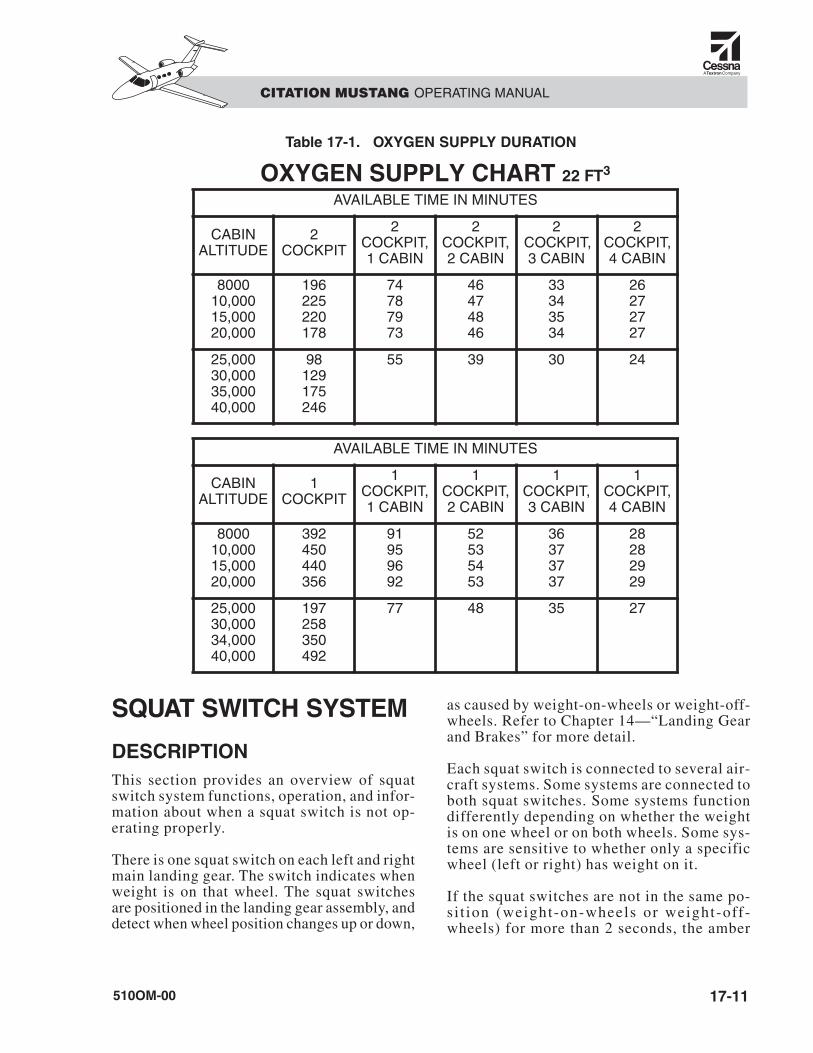
LIMITATIONSTable 17-1 indicates approximate normal du-ration of oxygen supply with different num-bers of users.
Due to human physiological limita-tions, the passenger oxygen systemis not satisfactory for continuous op-eration above 25,000 feet cabin alti-tude. The crew oxygen system is notsatisfactory for continuous opera-tion above 40,000 feet cabin altitude.Individual physiological limitationsmay vary. If crew or passengers ex-perience hypoxia symptoms, descendto a lower cabin altitude.
No smoking when oxygen is beingused or following use of passengeroxygen until lanyards have been reinstalled.
Oil, grease, soap, lipstick, lip balm,and other fatty materials constitutea serious fire hazard when in contactwith oxygen.
Oxygen use limitations are further governed bythe applicable regulations. In the U.S.A., thepilot must have the oxygen mask on his face dur-ing normally pressurized flight for single-pilotPart 135 operations above FL 250 or above sin-gle-pilot Part 91 operations above FL 350.
EMERGENCY/ABNORMALFor specific information on emergency/ab-normal procedures, refer to the appropriateFAA-approved abbreviated checklist or AFM.
CAUTION
WARNING
WARNING
Figure 17-13. Oxygen Bottle
SQUAT SWITCH SYSTEM
DESCRIPTIONThis section provides an overview of squatswitch system functions, operation, and infor-mation about when a squat switch is not op-erating properly.
There is one squat switch on each left and rightmain landing gear. The switch indicates whenweight is on that wheel. The squat switchesare positioned in the landing gear assembly, anddetect when wheel position changes up or down,
as caused by weight-on-wheels or weight-off-wheels. Refer to Chapter 14—“Landing Gearand Brakes” for more detail.
Each squat switch is connected to several air-craft systems. Some systems are connected toboth squat switches. Some systems functiondifferently depending on whether the weightis on one wheel or on both wheels. Some sys-tems are sensitive to whether only a specificwheel (left or right) has weight on it.
If the squat switches are not in the same po-si t ion (weight-on-wheels or weight-off-wheels) for more than 2 seconds, the amber
510OM-00 17-11
CITATION MUSTANG OPERATING MANUAL
OXYGEN SUPPLY CHART 22 FT3
AVAILABLE TIME IN MINUTES
CABIN ALTITUDE
2COCKPIT
2COCKPIT, 1 CABIN
2COCKPIT, 2 CABIN
2 COCKPIT, 3 CABIN
2COCKPIT, 4 CABIN
800010,00015,00020,000
196225220178
74787973
46474846
33343534
26272727
25,00030,00035,00040,000
98129175246
55 39 30 24
AVAILABLE TIME IN MINUTES
CABIN ALTITUDE
1COCKPIT
1COCKPIT, 1 CABIN
1COCKPIT, 2 CABIN
1COCKPIT, 3 CABIN
1COCKPIT, 4 CABIN
800010,00015,00020,000
392450440356
91959692
52535453
36373737
28282929
25,00030,00034,00040,000
197258350492
77 48 35 27
Table 17-1. OXYGEN SUPPLY DURATION

CAS message WOW MISCOMPARE warns ofthe difference.
Malfunctions of the squat switchesand their associated circuits maycause abnormal functioning of any orall of the aircraft systems that usesquat switch information.
Dependent SystemsThe following systems require squat switch in-formation for normal functioning:
• External doors
• Engine/FADEC
• Pneumatics
• Windshield anti-ice
• Air conditioning
• Pressurization
• Landing gear
• Brakes (antiskid)
• Avionics
• Stall warning
CONTROLS AND INDICATIONSL and R SQUAT SWITCH CircuitBreakers
Each squat switch (left and right) is poweredthrough the corresponding L or R SQUATSWITCH circuit breaker in the ENGINE SYS-TEMS section of the corresponding CB panel(left or right).
WOW MISCOMPARE Message
The amber CAS message WOW MISCOMPAREindicates that the squat switch system is indi-cating different status (miscompare) of the twoswitches. One squat switch appears to indicateweight-on-wheels while the other appears toindicate weight-off-wheels. The message doesnot display until the miscompare has continued
for 2 seconds. This allows for momentary dif-ferences during takeoff and landing.
The miscompare may be caused by:
• Different wheel positions
• Stuck squat switch
• Electrical short or open circuit
• Problems with the multi-function PCB
• Popped L or R SQUAT SWITCH circuitbreaker
• Loss of power to a squat switch
EMERGENCY/ABNORMALFor specific information on emergency/abnor-mal procedures, refer to the appropriate abbre-viated checklists or the FAA-approved AFM.
CAUTION
510OM-0017-12
CITATION MUSTANG OPERATING MANUAL


![Dse2012 Cutoff Cap2[1]](https://static.fdocuments.us/doc/165x107/55cf9d58550346d033ad3be3/dse2012-cutoff-cap21.jpg)


![t New CUBEs with Heavy Attitude t€¦ · METAL ZONE, EXTREME), GAIN Knob, VOLUME Knob, [EQUALIZER] BASS Knob, MIDDLE Knob, TREBLE Knob Indicators CLEAN Channel, LEAD Channel Connectors](https://static.fdocuments.us/doc/165x107/6067859789f730682b1d8a48/t-new-cubes-with-heavy-attitude-t-metal-zone-extreme-gain-knob-volume-knob.jpg)


![New t New CUBEs with Heavy Attitude t - American Musical Supply · 2013. 11. 26. · METAL ZONE, EXTREME), GAIN Knob, VOLUME Knob, [EQUALIZER] BASS Knob, MIDDLE Knob, TREBLE Knob](https://static.fdocuments.us/doc/165x107/6067859789f730682b1d8a47/new-t-new-cubes-with-heavy-attitude-t-american-musical-supply-2013-11-26.jpg)
