CiscoIOSLISPApplication(Note(Series:(( AccessControlLists( ·...
13
Printed in USA © 2011 Cisco Systems, Inc. All rights reserved. This document is Cisco Public Information. Page 1 of 1 Cisco IOS LISP Application Note Series: Access Control Lists Version 1.1 (28 April 2011) Background The LISP Application Note Series provides targeted information that focuses on the integration and configuration of relevant Cisco IOS features in conjunction with the deployment of LISP. LISP (Locator/ID Separation Protocol) is not a feature, but rather a nextgeneration routing architecture which implements a new semantic for IP addressing that creates two namespaces: Endpoint Identifiers (EIDs), which are assigned to endhosts, and Routing Locators (RLOCs), which are assigned to devices (primarily routers) that make up the global routing system. Creating separate namespaces for EIDs and RLOCs creates a level of indirection that yields many advantages over a single namespace (i.e. the current IP address concept) including: improved scalability of the routing system through greater aggregation of RLOCs, improved multihoming efficiency, ingress traffic engineering, and the ability to move EIDs without breaking sessions (mobility). LISP also was designed at the outset to be Address Family agnostic, and thus handles multiple AF’s seamlessly making its use ideal in IPv6 transition solutions. This and other LISP Application Notes in this series assume a working knowledge of LISP and are not intended to provide basic information on its usecases, or guidelines on configuration and deployment. These details can be found in the Cisco LISP Command Reference Guide, Cisco LISP Configuration Guide, (References [1]) and other information available at http://lisp.cisco.com . Application Note Organization Like all Application Notes in the LISP series, this application note is organized into three main sections. 1. Concept Overview – This section provides a brief description of the feature or technology being addressed in this Application Note in the context of a LISP implementation. 2. Concept Details – This section provides a detailed description of the feature or technology and its interaction with LISP, and a description of its (typical) usage in deployment. 3. Concept Examples – This section provides detailed testing of the feature or technology. This provides verification of the detailed descriptions, and also allows network administrators to set up a similar LISP environment and repeat the feature test. Comments and corrections are welcome. Please direct all queries to: [email protected].
Transcript of CiscoIOSLISPApplication(Note(Series:(( AccessControlLists( ·...

Printed in USA © 2011 Cisco Systems, Inc. All rights reserved. This document is Cisco Public Information. Page 1 of 1
Cisco IOS LISP Application Note Series: Access Control Lists Version 1.1 (28 April 2011)
Background
The LISP Application Note Series provides targeted information that focuses on the integration and configuration of relevant Cisco IOS features in conjunction with the deployment of LISP.
LISP (Locator/ID Separation Protocol) is not a feature, but rather a next-‐generation routing architecture which implements a new semantic for IP addressing that creates two namespaces: Endpoint Identifiers (EIDs), which are assigned to end-‐hosts, and Routing Locators (RLOCs), which are assigned to devices (primarily routers) that make up the global routing system. Creating separate namespaces for EIDs and RLOCs creates a level of indirection that yields many advantages over a single namespace (i.e. the current IP address concept) including: improved scalability of the routing system through greater aggregation of RLOCs, improved multi-‐homing efficiency, ingress traffic engineering, and the ability to move EIDs without breaking sessions (mobility). LISP also was designed at the outset to be Address Family agnostic, and thus handles multiple AF’s seamlessly making its use ideal in IPv6 transition solutions.
This and other LISP Application Notes in this series assume a working knowledge of LISP and are not intended to provide basic information on its use-‐cases, or guidelines on configuration and deployment. These details can be found in the Cisco LISP Command Reference Guide, Cisco LISP Configuration Guide, (References [1]) and other information available at http://lisp.cisco.com.
Application Note Organization
Like all Application Notes in the LISP series, this application note is organized into three main sections.
1. Concept Overview – This section provides a brief description of the feature or technology being addressed in this Application Note in the context of a LISP implementation.
2. Concept Details – This section provides a detailed description of the feature or technology and its interaction with LISP, and a description of its (typical) usage in deployment.
3. Concept Examples – This section provides detailed testing of the feature or technology. This provides verification of the detailed descriptions, and also allows network administrators to set up a similar LISP environment and repeat the feature test.
Comments and corrections are welcome. Please direct all queries to: lisp-‐[email protected].

Printed in USA © 2011 Cisco Systems, Inc. All rights reserved. This document is Cisco Public Information. Page 2 of 2
Concept Overview: Cisco IOS Access Control Lists and LISP
The Access Control List (ACL) is perhaps one of the most fundamental features of Cisco IOS and its use is familiar to network administrators for many applications including: restricting traffic flows, classifying and identifying interesting traffic for other functions such as Network Address Translation (NAT), Quality of Service (QoS), and IP Security (IPSec), and for filtering routing updates and many others. This application note describes the use of ACLs for restricting traffic within LISP implementations.
When considering the deployment of ACLs with LISP, the following aspects are important.
1. LISP encapsulation utilizes a UDP header just prior to the LISP header for all packets to distinguish between two distinct packet groups: LISP control plane packets, which utilize a UDP destination port of 4342, and LISP data plane packets, which utilize a UDP destination port of 4341. ACLs may need to consider this distinction between these two groups of packets.
2. LISP is an encapsulation protocol and, because ACLs only filter based on Layer 3 and Layer 4 header information, ACLs may need to be applied at a specific point or at several different points within the packet forwarding and LISP encapsulation process in order to implement a site security policy. The application point and direction of the ACL will dictate whether EID namespace or RLOC namespace is used within the ACL itself. Packets can be filtered using EID namespace just prior to LISP encapsulation or just after LISP decapsulation; packets can be filtered using RLOC namespace just after LISP encapsulation or just prior to LISP decapsulation.
This application note covers both of the above topics in detail.
Concept Details: Cisco IOS Access Control Lists and LISP
LISP Packets
For the purposes of this application note, LISP packets can be separated into two groups, as follows:
• LISP control plane packets – LISP-‐enabled devices create control plane packets to register EID-‐prefixes with Map-‐Servers, to conduct EID-‐to-‐RLOC mapping resolutions, and for various other protocol operations purposes. The UDP destination port 4342 in the LISP packet header indicates that it contains a LISP control plane packet. LISP control plane packets are handled directly by the LISP device itself (i.e. the device route processor). As with other types of control plane traffic, protecting the control plane from abuse is beneficial to network health (see Reference [5]). LISP control plane message types are described in Reference [2].
• LISP data plane packets –LISP-‐enabled devices encapsulate data plane packets to forward user traffic between LISP sites. The UDP destination port 4341 in the LISP packet header indicates that it contains a LISP data plane packet. LISP data plane packets are handled in the fast path (hardware/CEF processing) of the LISP device. The LISP device is only responsible for encapsulating and forwarding, or decapsulating and forwarding these packets.
LISP data plane packet encapsulation consists of an outer IPv4 or IPv6 header utilizing RLOC namespace addresses, and a UDP header and LISP header, all being added to the original packet. Figure 1 below shows a typical LISP data plane packet encapsulation with an IPv4 EID and IPv4 RLOC. ACLs can be applied at several different configuration points, giving them the ability to operate on packets either before or after LISP encapsulation (or both), as desired, to meet the site security requirements. Since ACLs only operate on the Layer 3 and Layer 4 headers of a packet, ACLs that are applied to packets after LISP encapsulation will only be able to operate on the outer header illustrated in Figure 1. In this case the ACL would see only the RLOC namespace addresses and the LISP UDP header. ACLs that are applied to packets

Printed in USA © 2011 Cisco Systems, Inc. All rights reserved. This document is Cisco Public Information. Page 3 of 3
before LISP encapsulation or after LISP decapsulation will operate on the original, host-‐generated packets. These are the addresses that become the inner header illustrated in Figure 1.
Figure 1. LISP data plane packet format (draft-‐09 header)
LISP Processing and ACLs
In Cisco IOS, ACLs are applied to interfaces, and from a LISP perspective, three interfaces are relevant to ACL discussions: the LISP Site-‐facing interface, the Core-‐facing interface, and the LISP0 interface, as illustrated in Figure 2. At each of these different application points, ACLs can be applied in the in (ingress) and out (egress) direction, leading to the possibility of six unique ACLs per address family (IPv4 and IPv6). This gives them the ability to operate on packets either before or after LISP encapsulation (or both), as desired, to meet the site security requirements.
Figure 2. Conceptual interfaces and ACL application points with LISP

Printed in USA © 2011 Cisco Systems, Inc. All rights reserved. This document is Cisco Public Information. Page 4 of 4
The LISP process in IOS creates the LISP0 virtual interface, as illustrated in Figure 2, as a reference point for encapsulation and decapsulation operations. This LISP0 virtual interface, described in detail in the Application Note available at Reference [1], serves as the natural boundary between the EID and RLOC namespaces for the Ingress Tunnel Router (ITR) or Egress Tunnel Router (ETR) – commonly referred to as an xTR when both LISP functions are deployed. Egress features are applied to packets that are leaving the router via LISP, just prior to LISP encapsulation. Similarly, ingress features are applied to packets that are arriving from LISP, just after LISP decapsulation. Note that in both cases, the LISP0 ingress and egress feature application points are in the EID namespace.
It is important to understand that these three application points do not offer the same filtering options, due to the LISP encapsulation process. Referring to Figure 2, the following observations can be made about the point of application and functionality of ACLs used within a LISP deployment:
• ACLs can be applied in the in (ingress) direction and the out (egress) direction on the LISP site-‐facing interface, shown as E1/0 in the figure. When ACLs are applied here, filtering will be applied to user-‐packets in the EID namespace either before (potential) LISP encapsulation (when applied in the in direction), or after LISP decapsulation (when applied in the out direction).
• ACLs can be applied in the in (ingress) direction and the out (egress) direction on the SP Core/Internet-‐facing interface, shown as E0/0 in the figure. When ACLs are applied here, filtering will be applied to packets in the RLOC namespace either before LISP decapsulation (when applied in the in direction), or after LISP encapsulation (when applied in the out direction).
• ACLs can be applied in the in (ingress) direction and the out (egress) direction on the LISP0 interface. The LISP0 interface is logical and simply provides a reference point for the application of CEF features, like ACLs. ACLs applied here always refer to user-‐packets in the EID namespace (i.e. not LISP encapsulated). An ACL applied in the in direction refers to user-‐packets that have just been decapsulated and are being forwarded toward the LISP site, and an ACL applied in the out direction refers to user-‐packets being sent to LISP to be encapsulated and then forwarded toward the SP Core/Internet.
No preferential manner for applying ACLs is implied or intended. The selected interface(s) and direction(s) should be based on site needs in terms of security requirements and management support. For example, sites may find that that existing ACLs can be reapplied without modification to the LISP0 interface. This document is not intended to provide guidance on specific site security policies. A thorough review of existing policies, combined with an understanding of the use of ACLs with LISP, and adequate validation testing should be completed prior to any production deployments of any technology.
Caveats and Notes Related to ACLs
The following caveats and notes are applicable to ACLs for use with LISP:
1. As is always the case with ACLs and Cisco IOS devices, the use of the log keyword can be used to provide additional detail about source and destinations for a given protocol. Although this keyword provides valuable insight into the details of ACL hits, using the log keyword results in packets matching the access-‐list statement being handled by process switching (slow path) instead of CEF switching, resulting in platform-‐dependent performance impacts.
2. In Cisco IOS devices, there should be no performance difference between using an ACL on a physical (or logical) interface, and using an ACL on the LISP 0 interface. In both cases, assuming the log keyword is not used, packets are CEF-‐switched and should experience that same forwarding performance through the router. Therefore, the primary consideration should be to develop and apply ACLs that best meet the security requirements of the site.

Printed in USA © 2011 Cisco Systems, Inc. All rights reserved. This document is Cisco Public Information. Page 5 of 5
In general, normal Cisco IOS ACL rules are applicable, and normal procedures for the construction of ACLs should be followed.
Concept Examples: Cisco IOS Access Control Lists and LISP
The following example demonstrates the use of ACLs within a LISP deployment. This example is provided only as validation for the above ACL discussions, and not as an indication of appropriate ACL deployments for meeting site security requirements.
Initial LISP Configuration
The test network topology for this example is illustrated in Figure 3. In this test network, the following elements are defined:
• LISP Site A, which includes the LISP IPv4 EID-‐prefix 192.168.1.0/24. The Cisco IOS router xTR-‐A is the LISP xTR, and it registers with the Map-‐Server located at 10.0.0.10. The router Site-‐A provides a convenient host for traffic source/destination during the ACL validation testing. The ACLs will all be applied only to xTR-‐A.
• LISP Site B, which includes the LISP IPv4 EID-‐prefix 192.168.2.0/24. The Cisco IOS router xTR-‐B is the LISP xTR, and it registers with the Map-‐Server located at 10.0.0.10. The router Site-‐B provides a convenient host for traffic source/destination during the ACL validation testing.
• SP Core/Internet, which includes the router Core, represents the public (RLOC-‐space) through which the LISP sites communicate. This core network is IPv4-‐only in this example.
• Map-‐Server/Map-‐Resolver, which provides mapping-‐resolution services for the LISP sites. The Cisco ISO router MS/MR is deployed as a LISP Map-‐Server/Map-‐Resolver. The xTRs from LISP Site A and LISP Site B register to this device, and use it for EID-‐to-‐RLOC mapping resolution.
This is a fairly basic network topology, but it is quite adequate for demonstrating the use of ACLs within a LISP deployment. Full configurations for each device are included in the Appendix of this application note.
Figure 3. Cisco IOS ACL use with LISP example — test network topology
Cisco IOS ACL Examination
The ACL examination testing documented here applies a unique ACL to each possible location and direction that is relevant to the LISP deployment using router xTR-‐A as the device under test (DUT). Thus, six separate ACLs in total are applied: two (in, out) to the site-‐facing interface E0/1, two (in, out) to the Internet-‐facing interface E0/0, and two (in, out) to the LISP0 interface. The location and direction of these six ACLs is illustrated in Figure 4.

Printed in USA © 2011 Cisco Systems, Inc. All rights reserved. This document is Cisco Public Information. Page 6 of 6
Figure 4. Cisco IOS ACL use with LISP example — ACL deployment locations
Source-‐pings from Site-‐A (192.168.1.1) to Site-‐B (192.168.2.1) are used as traffic generators for this ACL testing. All six uniquely identified ACLs have identical elements. In this way, the counters displayed for each ACL indicate the directionality and specific Layer 3 header information at each test point. Therefore, all ACLs are constructed with the following entries:
permit icmp host 192.168.1.1 host 192.168.2.1 echo permit icmp host 192.168.2.1 host 192.168.1.1 echo-reply permit udp host 10.0.0.2 host 10.0.0.6 permit udp host 10.0.0.6 host 10.0.0.2 permit ip any any
Step 1. Preparations for testing ACLs
First, clear the access-‐list counters on xTR-‐A in order to minimize ambiguity during testing.
xTR-A#clear access-list counters
Step 2. Test the ACLs with a source-‐ping.
Source-‐ping Site B EID (192.168.2.1) with a source of the Site A EID (192.168.1.1), using a repeat value of 100. All packets should succeed.
SiteA#ping 192.168.2.1 so 192.168.1.1 repeat 100 Type escape sequence to abort. Sending 100, 100-byte ICMP Echos to 192.168.2.1, timeout is 2 seconds:

Printed in USA © 2011 Cisco Systems, Inc. All rights reserved. This document is Cisco Public Information. Page 7 of 7
Packet sent with a source address of 192.168.1.1 !!!!!!!!!!!!!!!!!!!!!!!!!!!!!!!!!!!!!!!!!!!!!!!!!!!!!!!!!!!!!!!!!!!!!! !!!!!!!!!!!!!!!!!!!!!!!!!!!!!! Success rate is 100 percent (100/100), round-trip min/avg/max = 1/1/8 ms
All 100 echo/echo-‐reply packets succeeded. This is also reflected in the value of the counters in the ACLs.
Step 3. Review the ACL counters.
Show each ACL and observer which counters have incremented by 100.
xTR-A#sh ip access-lists lisp0-out Extended IP access list lisp0-out 10 permit icmp host 192.168.1.1 host 192.168.2.1 echo (100 matches) 20 permit icmp host 192.168.2.1 host 192.168.1.1 echo-reply 30 permit udp host 10.0.0.2 host 10.0.0.6 40 permit udp host 10.0.0.6 host 10.0.0.2 50 permit ip any any
xTR-A#sh ip access-lists site-in Extended IP access list site-in 10 permit icmp host 192.168.1.1 host 192.168.2.1 echo (100 matches) 20 permit icmp host 192.168.2.1 host 192.168.1.1 echo-reply 30 permit udp host 10.0.0.2 host 10.0.0.6 40 permit udp host 10.0.0.6 host 10.0.0.2 50 permit ip any any
xTR-A#show ip access-lists lisp0-in Extended IP access list lisp0-in 10 permit icmp host 192.168.1.1 host 192.168.2.1 echo 20 permit icmp host 192.168.2.1 host 192.168.1.1 echo-reply (100 matches) 30 permit udp host 10.0.0.2 host 10.0.0.6 40 permit udp host 10.0.0.6 host 10.0.0.2 50 permit ip any any
xTR-A#sh ip access-lists site-out Extended IP access list site-out 10 permit icmp host 192.168.1.1 host 192.168.2.1 echo 20 permit icmp host 192.168.2.1 host 192.168.1.1 echo-reply (100 matches) 30 permit udp host 10.0.0.2 host 10.0.0.6 40 permit udp host 10.0.0.6 host 10.0.0.2 50 permit ip any any
xTR-A#sh ip access-lists rloc-out Extended IP access list rloc-out 10 permit icmp host 192.168.1.1 host 192.168.2.1 echo 20 permit icmp host 192.168.2.1 host 192.168.1.1 echo-reply 30 permit udp host 10.0.0.2 host 10.0.0.6 (100 matches) 40 permit udp host 10.0.0.6 host 10.0.0.2 50 permit ip any any
xTR-A#sh ip access-lists rloc-in Extended IP access list rloc-in 10 permit icmp host 192.168.1.1 host 192.168.2.1 echo 20 permit icmp host 192.168.2.1 host 192.168.1.1 echo-reply 30 permit udp host 10.0.0.2 host 10.0.0.6 40 permit udp host 10.0.0.6 host 10.0.0.2 (100 matches) 50 permit ip any any

Printed in USA © 2011 Cisco Systems, Inc. All rights reserved. This document is Cisco Public Information. Page 8 of 8
Several observations can be made based on the above show command output.
1. As expected, the ACLs applied to the LISP0 interface and the site-‐facing interface (E0/1 in this case) show the same results, but in the opposite directions. That is, lisp0-‐out and site-‐in show the same results, and lisp0-‐in and site-‐out show the same results. This reflects the directional behavior of the ACLs on the respective interface. The ACLs lisp0-‐out and site-‐in both see the echo packets with source 192.168.1.1 and destination 192.168.2.1, while the ACLs lisp0-‐in and site-‐out both see the echo-‐reply packets with source 192.168.2.1 and destination 192.168.1.1. When developing and applying ACLs to meet a site security requirement, it may be useful to consider that an ACL only needs to be applied to the LISP0 interface (one place) as opposed to potentially numerous site-‐facing interfaces when filtering using EID addresses.
2. ACLs rloc-‐in and rloc-‐out are the only ACLs that see the LISP-‐encapsulated (outer header) addresses. When developing and applying ACLs to meet a site security requirement, consider that an ACL can only be applied to core-‐facing interfaces in order to filter on RLOC addresses.
Based on these observations, it is clear that LISP data plane packets can be filtered by ACLs applied to site-‐facing interfaces or the LISP0 interface, using the EID addresses. When applied to Core-‐facing interfaces, ACLs can only filter LISP data plane packets based on the UDP destination port 4341 and RLOC addresses. It is also clear that LISP control plane packets can only be filtered by ACLs applied to Core-‐facing interfaces, and then only based on the UDP destination port 4342 and RLOC addresses.
IPv6 Considerations
The mixed address family capabilities of LISP allow for both IPv4 and IPv6 packets to be used as EIDs and as RLOCs, with the following combinations being possible (lisp site address-‐family, rloc address-‐family): (IPv4, IPv4), (IPv4, IPv6), (IPv6, IPv4), and (IPv6, IPv6). It is possible then that both IPv4 and IPv6 ACLs may be required to satisfy site security needs.
Only IPv4 ACLs were used in this example test case; IPv6 packets and ACLs were not illustrated. However, the use and application of IPv6 ACLs is exactly the same as the use and application of IPv4 ACLs in terms of interactions (interfaces and directions) with LISP. Whether IPv4 and/or IPv6 ACLs are required is dictated by the site security needs.
As an example, note that the both LISP sites shown in Figure 3 have both IPv4 and IPv6 EIDs (Site-‐A: 192.168.1.0/24, 2001:db8:a::/48, and Site-‐B: 192.168.2.0/24, 2001:db8:b::/48). Only the IPv4 EIDs were used in the example tests above. Note also that the Core network and both sites only use IPv4 addresses. It is quite simple with LISP to connect these two IPv6 islands over the IPv4 infrastructure. In this case, IPv6 ACLs would be required on the site-‐facing interfaces and the LISP0 interface, and IPv4 ACLs would be required on the core-‐facing interface since the original packets would be IPv6 and the LISP0-‐encapsulted packets would use IPv4 RLOCs (outer header).
Conclusions
This application note described the use of ACLs with LISP implementations. ACLs are one of the most fundamental tools available to network administrators for restricting traffic flows and implementing site security policies. The interactions of ACLs with LISP operations were described, and an example using IPv4 EIDs and RLOCs was used to illustrate these concepts. The LISP0 interface is logical and simply provides a reference point for the application of CEF features, like ACLs. Applying ACLs to LISP0 only affects packets in EID namespace and can be a helpful for consolidating ACLs when there are numerous site-‐facing interfaces. In general, the selected interface(s) and direction(s) should be based on site needs in terms of security requirements and management support. Finally, the mixed address family capabilities of LISP were highlighted, and the potential impact of this on the selection of appropriate ACLs was described.

Printed in USA © 2011 Cisco Systems, Inc. All rights reserved. This document is Cisco Public Information. Page 9 of 9
LISP Resources
1. LISP Documentation, including the LISP Command Reference Guide, LISP Configuration Guide, and LISP Lab Test Guide, which can be found here: http://lisp.cisco.com/lisp_down.html
2. LISP IETF Draft RFCS can be found here: http://tools.ietf.org/wg/lisp/
3. Cisco Marketing Information about LISP can be found here: http://www.cisco.com/go/lisp
4. LISP Beta Network information can be found here: http://www.lisp4.net and http://www.lisp6.net
5. “Router Security Strategies: Securing IP Network Traffic Planes,” Cisco Press. http://www.ciscopress.com/bookstore/product.asp?isbn=1587053365
Comments and corrections are welcome. Please direct all queries to: lisp-‐[email protected].
Printed in USA © 2011 Cisco Systems, Inc. All rights reserved. This document is Cisco Public Information. Page 10 of 10
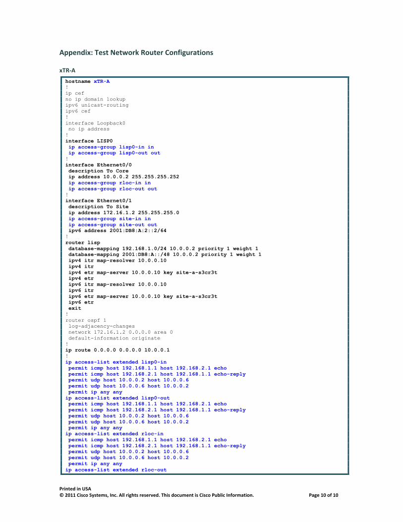
Appendix: Test Network Router Configurations
xTR-‐A
hostname xTR-A ! ip cef no ip domain lookup ipv6 unicast-routing ipv6 cef ! interface Loopback0 no ip address ! interface LISP0 ip access-group lisp0-in in ip access-group lisp0-out out ! interface Ethernet0/0 description To Core ip address 10.0.0.2 255.255.255.252 ip access-group rloc-in in ip access-group rloc-out out ! interface Ethernet0/1 description To Site ip address 172.16.1.2 255.255.255.0 ip access-group site-in in ip access-group site-out out ipv6 address 2001:DB8:A:2::2/64 ! router lisp database-mapping 192.168.1.0/24 10.0.0.2 priority 1 weight 1 database-mapping 2001:DB8:A::/48 10.0.0.2 priority 1 weight 1 ipv4 itr map-resolver 10.0.0.10 ipv4 itr ipv4 etr map-server 10.0.0.10 key site-a-s3cr3t ipv4 etr ipv6 itr map-resolver 10.0.0.10 ipv6 itr ipv6 etr map-server 10.0.0.10 key site-a-s3cr3t ipv6 etr exit ! router ospf 1 log-adjacency-changes network 172.16.1.2 0.0.0.0 area 0 default-information originate ! ip route 0.0.0.0 0.0.0.0 10.0.0.1 ! ip access-list extended lisp0-in permit icmp host 192.168.1.1 host 192.168.2.1 echo permit icmp host 192.168.2.1 host 192.168.1.1 echo-reply permit udp host 10.0.0.2 host 10.0.0.6 permit udp host 10.0.0.6 host 10.0.0.2 permit ip any any ip access-list extended lisp0-out permit icmp host 192.168.1.1 host 192.168.2.1 echo permit icmp host 192.168.2.1 host 192.168.1.1 echo-reply permit udp host 10.0.0.2 host 10.0.0.6 permit udp host 10.0.0.6 host 10.0.0.2 permit ip any any ip access-list extended rloc-in permit icmp host 192.168.1.1 host 192.168.2.1 echo permit icmp host 192.168.2.1 host 192.168.1.1 echo-reply permit udp host 10.0.0.2 host 10.0.0.6 permit udp host 10.0.0.6 host 10.0.0.2 permit ip any any ip access-list extended rloc-out
Printed in USA © 2011 Cisco Systems, Inc. All rights reserved. This document is Cisco Public Information. Page 11 of 11
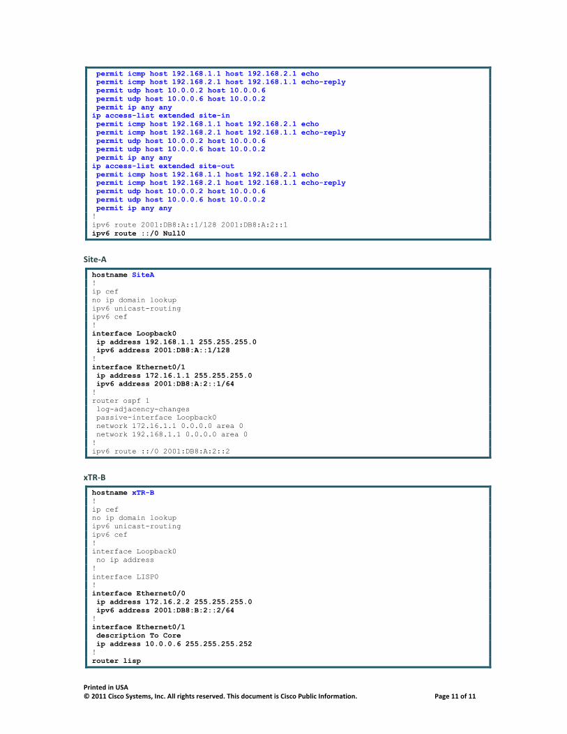
permit icmp host 192.168.1.1 host 192.168.2.1 echo permit icmp host 192.168.2.1 host 192.168.1.1 echo-reply permit udp host 10.0.0.2 host 10.0.0.6 permit udp host 10.0.0.6 host 10.0.0.2 permit ip any any ip access-list extended site-in permit icmp host 192.168.1.1 host 192.168.2.1 echo permit icmp host 192.168.2.1 host 192.168.1.1 echo-reply permit udp host 10.0.0.2 host 10.0.0.6 permit udp host 10.0.0.6 host 10.0.0.2 permit ip any any ip access-list extended site-out permit icmp host 192.168.1.1 host 192.168.2.1 echo permit icmp host 192.168.2.1 host 192.168.1.1 echo-reply permit udp host 10.0.0.2 host 10.0.0.6 permit udp host 10.0.0.6 host 10.0.0.2 permit ip any any ! ipv6 route 2001:DB8:A::1/128 2001:DB8:A:2::1 ipv6 route ::/0 Null0
Site-‐A
hostname SiteA ! ip cef no ip domain lookup ipv6 unicast-routing ipv6 cef ! interface Loopback0 ip address 192.168.1.1 255.255.255.0 ipv6 address 2001:DB8:A::1/128 ! interface Ethernet0/1 ip address 172.16.1.1 255.255.255.0 ipv6 address 2001:DB8:A:2::1/64 ! router ospf 1 log-adjacency-changes passive-interface Loopback0 network 172.16.1.1 0.0.0.0 area 0 network 192.168.1.1 0.0.0.0 area 0 ! ipv6 route ::/0 2001:DB8:A:2::2
xTR-‐B
hostname xTR-B ! ip cef no ip domain lookup ipv6 unicast-routing ipv6 cef ! interface Loopback0 no ip address ! interface LISP0 ! interface Ethernet0/0 ip address 172.16.2.2 255.255.255.0 ipv6 address 2001:DB8:B:2::2/64 ! interface Ethernet0/1 description To Core ip address 10.0.0.6 255.255.255.252 ! router lisp

Printed in USA © 2011 Cisco Systems, Inc. All rights reserved. This document is Cisco Public Information. Page 12 of 12
database-mapping 192.168.2.0/24 10.0.0.6 priority 1 weight 1 database-mapping 2001:DB8:B::/48 10.0.0.6 priority 1 weight 1 ipv4 itr map-resolver 10.0.0.10 ipv4 itr ipv4 etr map-server 10.0.0.10 key site-b-s3cr3t ipv4 etr ipv6 itr map-resolver 10.0.0.10 ipv6 itr ipv6 etr map-server 10.0.0.10 key site-b-s3cr3t ipv6 etr exit ! router ospf 1 log-adjacency-changes network 172.16.2.2 0.0.0.0 area 0 default-information originate ! ip route 0.0.0.0 0.0.0.0 10.0.0.5 ! ipv6 route 2001:DB8:B::1/128 2001:DB8:B:2::1 ipv6 route ::/0 Null0
Site-‐B
hostname SiteB ! ip cef no ip domain lookup ipv6 unicast-routing ipv6 cef ! interface Loopback0 ip address 192.168.2.1 255.255.255.0 ipv6 address 2001:DB8:B::1/128 ! interface Ethernet0/0 ip address 172.16.2.1 255.255.255.0 ipv6 address 2001:DB8:B:2::1/64 ! router ospf 1 log-adjacency-changes passive-interface Loopback0 network 172.16.2.1 0.0.0.0 area 0 network 192.168.2.1 0.0.0.0 area 0 ! ipv6 route ::/0 2001:DB8:2::2
MS-‐MR
hostname MS-MR ! vrf definition lisp rd 1:1 ! address-family ipv4 exit-address-family ! address-family ipv6 exit-address-family ! ip cef no ip domain lookup ipv6 unicast-routing ipv6 cef ! router lisp site Site-A description LISP Site A authentication-key site-a-s3cr3t

Printed in USA © 2011 Cisco Systems, Inc. All rights reserved. This document is Cisco Public Information. Page 13 of 13
eid-prefix 192.168.1.0/24 eid-prefix 2001:DB8:A::/48 exit ! site Site-B description LISP Site B authentication-key site-b-s3cr3t eid-prefix 192.168.2.0/24 eid-prefix 2001:DB8:B::/48 exit ! ipv4 map-server ipv4 map-resolver ipv4 alt-vrf lisp ipv6 map-server ipv6 map-resolver ipv6 alt-vrf lisp exit ! interface LISP0 ! interface Ethernet0/0 description To Core ip address 10.0.0.10 255.255.255.252 ! ip route 0.0.0.0 0.0.0.0 10.0.0.9
Core
hostname Core ! ip cef no ip domain lookup no ipv6 cef ! interface Loopback0 ip address 10.100.0.1 255.255.255.0 ! interface Ethernet0/0 description To xTR-A ip address 10.0.0.1 255.255.255.252 ! interface Ethernet0/1 description To xTR-B ip address 10.0.0.5 255.255.255.252 ! interface Ethernet0/2 description To MS-MR ip address 10.0.0.9 255.255.255.252