Cisco Unified Operating System Administration web …...Cisco Unified Operating System...
24
Cisco Unified Operating System Administration web interface • ServerGroup, page 1 • Hardware Status, page 2 • Network Configuration, page 3 • Software Packages, page 4 • System Status, page 5 • IP Preferences, page 6 • Ethernet Configuration, page 7 • Publisher Settings, page 8 • NTP Server List, page 9 • SMTP Settings, page 10 • Time Settings, page 11 • Version Settings, page 12 • Certificate List, page 13 • Certificate Monitor, page 17 • IPSec Policy List, page 18 • Software Installation/Upgrade, page 21 • Ping Configuration, page 22 • Remote Access Configuration, page 23 ServerGroup The ServerGroup page appears when you choose Show > ServerGroup. Cisco Emergency Responder Administration Guide Release 10.0 1
Transcript of Cisco Unified Operating System Administration web …...Cisco Unified Operating System...

Cisco Unified Operating System Administrationweb interface
• ServerGroup, page 1
• Hardware Status, page 2
• Network Configuration, page 3
• Software Packages, page 4
• System Status, page 5
• IP Preferences, page 6
• Ethernet Configuration, page 7
• Publisher Settings, page 8
• NTP Server List, page 9
• SMTP Settings, page 10
• Time Settings, page 11
• Version Settings, page 12
• Certificate List, page 13
• Certificate Monitor, page 17
• IPSec Policy List, page 18
• Software Installation/Upgrade, page 21
• Ping Configuration, page 22
• Remote Access Configuration, page 23
ServerGroupThe ServerGroup page appears when you choose Show > ServerGroup.
Cisco Emergency Responder Administration Guide Release 10.0 1

Authorization Requirements
You must have platform administrator authority to access this page.
Description
Use the ServerGroup page to view information about the Emergency Responder servers in the server group.
The following table describes the ServerGroup page.
Table 1: ServerGroup page
DescriptionField
ServerGroup
Displays the name of the host.Hostname
Displays the IP address of the host.IP Address
Displays the alias of the hostAlias
Displays the node type of the host.Type of Node
Related Topics
View hardware status
Hardware StatusThe Hardware Status page appears when you choose Show > Hardware.
Authorization Requirements
You must have platform administrator authority to access this page.
Description
Use the Hardware Status page to view information about the Emergency Responder hardware.
The following table describes the Hardware Status page.
Table 2: Hardware Status page
DescriptionField
Hardware Resources
Model identity of the platform serverPlatform Type
Speed of the processorProcessor Speed
Cisco Emergency Responder Administration Guide Release 10.02
Cisco Unified Operating System Administration web interfaceHardware Status
DescriptionField
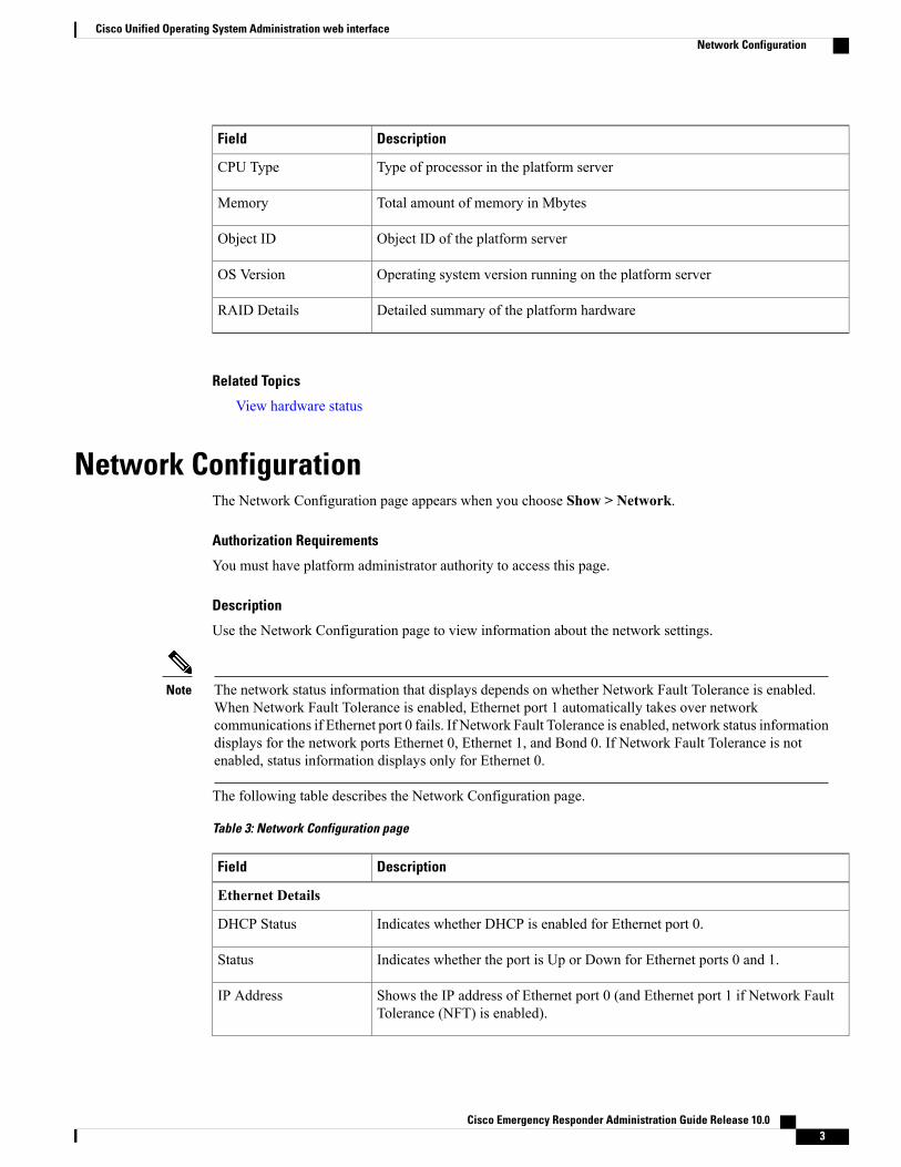
Type of processor in the platform serverCPU Type
Total amount of memory in MbytesMemory
Object ID of the platform serverObject ID
Operating system version running on the platform serverOS Version
Detailed summary of the platform hardwareRAID Details
Related Topics
View hardware status
Network ConfigurationThe Network Configuration page appears when you choose Show > Network.
Authorization Requirements
You must have platform administrator authority to access this page.
Description
Use the Network Configuration page to view information about the network settings.
The network status information that displays depends on whether Network Fault Tolerance is enabled.When Network Fault Tolerance is enabled, Ethernet port 1 automatically takes over networkcommunications if Ethernet port 0 fails. If Network Fault Tolerance is enabled, network status informationdisplays for the network ports Ethernet 0, Ethernet 1, and Bond 0. If Network Fault Tolerance is notenabled, status information displays only for Ethernet 0.
Note
The following table describes the Network Configuration page.
Table 3: Network Configuration page
DescriptionField
Ethernet Details
Indicates whether DHCP is enabled for Ethernet port 0.DHCP Status
Indicates whether the port is Up or Down for Ethernet ports 0 and 1.Status
Shows the IP address of Ethernet port 0 (and Ethernet port 1 if Network FaultTolerance (NFT) is enabled).
IP Address
Cisco Emergency Responder Administration Guide Release 10.0 3
Cisco Unified Operating System Administration web interfaceNetwork Configuration
DescriptionField
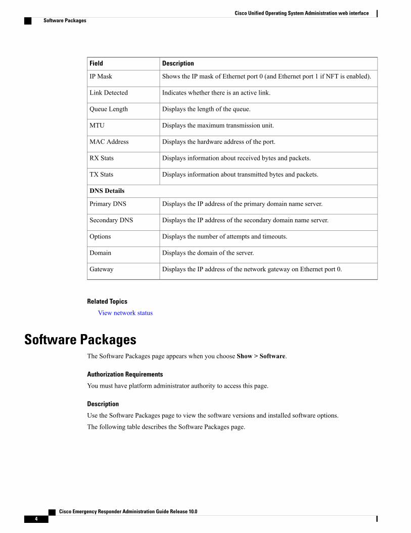
Shows the IP mask of Ethernet port 0 (and Ethernet port 1 if NFT is enabled).IP Mask
Indicates whether there is an active link.Link Detected
Displays the length of the queue.Queue Length
Displays the maximum transmission unit.MTU
Displays the hardware address of the port.MAC Address
Displays information about received bytes and packets.RX Stats
Displays information about transmitted bytes and packets.TX Stats
DNS Details
Displays the IP address of the primary domain name server.Primary DNS
Displays the IP address of the secondary domain name server.Secondary DNS
Displays the number of attempts and timeouts.Options
Displays the domain of the server.Domain
Displays the IP address of the network gateway on Ethernet port 0.Gateway
Related Topics
View network status
Software PackagesThe Software Packages page appears when you choose Show > Software.
Authorization Requirements
You must have platform administrator authority to access this page.
Description
Use the Software Packages page to view the software versions and installed software options.
The following table describes the Software Packages page.
Cisco Emergency Responder Administration Guide Release 10.04
Cisco Unified Operating System Administration web interfaceSoftware Packages

Table 4: Software Packages page
DescriptionField
Displays the software version that is running on the active and inactive partitions.Partition Versions
Displays the versions of installed software options that are installed on the activeversion.
Active Version InstalledSoftware Options
Displays the versions of installed software options that are installed on the inactiveversion.
Inactive Version InstalledSoftware Options
Related Topics
View installed software
System StatusThe System Status page appears when you choose Show > System.
Authorization Requirements
You must have platform administrator authority to access this page.
Description
Use the System Status page to view the status of the Emergency Responder system.
The following table describes the System Status page.
Table 5: System Status page
DescriptionField
Name of the Cisco UCS host where the Emergency Responder system is installed.Host Name
Date and time based on the continent and region that were specified during operatingsystem installation.
Date
Time zone that was chosen during installation.Time Zone
Locale of the system.Locale
Operating system version.Product Version
Platform version.Platform Version
Displays system uptime information.Uptime
Cisco Emergency Responder Administration Guide Release 10.0 5
Cisco Unified Operating System Administration web interfaceSystem Status

DescriptionField
Displays the percentage of CPU capacity that is idle, the percentage that is runningsystem processes, and the percentage that is running user processes.
CPU
Displays information about memory usage, including the amount of total memory,free memory, and used memory in kilobytes.
Memory
Displays the amount of total, free, and used disk space on the active disk.Disk/active
Displays the amount of total, free, and used disk space on the inactive disk.Disk/inactive
Displays the amount of total, free, and disk space that is used for disk logging.Disk/logging
Related Topics
View system status
IP PreferencesThe IP Preferences page appears when you choose Show > IP Preferences.
Authorization Requirements
You must have platform administrator authority to access this page.
Description
Use the IP Preferences page to view a list of registered ports that can be used by the system. The followingtable describes the IP Preferences page.
Table 6: IP Preferences page
DescriptionField
Name of the application using (listening on) the port.Application
Protocol used on this port (TCP, UDP, and so on).Protocol
Numeric port number.Port Number
Type of traffic allowed on this port:
• Public—All traffic allowed.
• Translated—All traffic allowed but forwarded to a different port.
• Private—Traffic only allowed from a defined set of remote servers, for example,other servers in the server group.
Type
Cisco Emergency Responder Administration Guide Release 10.06
Cisco Unified Operating System Administration web interfaceIP Preferences

DescriptionField
Traffic destined for this port get forwarded to the port listed in the Port Numbercolumn. This field applies to Translated type ports only.
Translated Port
Status of port usage:
• Enabled—In use by the application and opened by the firewall.
• Disabled—Blocked by the firewall and not in use.
Status
Brief description of how the port is used.Description
Related Topics
View IP preferences
Ethernet ConfigurationThe Ethernet Configuration page appears when you choose Settings > IP > Ethernet.
Authorization Requirements
You must have platform administrator authority to access this page.
Description
Use the Ethernet Configuration page to view or change Ethernet settings.
All Ethernet settings apply only to Eth0. You cannot configure any settings for Eth1. The maximumtransmission unit (MTU) on Eth0 defaults to 1500.
Note
The following table describes the Ethernet Configuration page.
Table 7: Ethernet Configuration page
DescriptionField
DHCP Information
Indicates whether DHCP is enabled or disabled and allows you to change the DHCPsetting using the pull-down menu.
DHCP
Host Information
Displays the server name (Display only—Cannot configure).Hostname
Port Information
Cisco Emergency Responder Administration Guide Release 10.0 7
Cisco Unified Operating System Administration web interfaceEthernet Configuration
DescriptionField
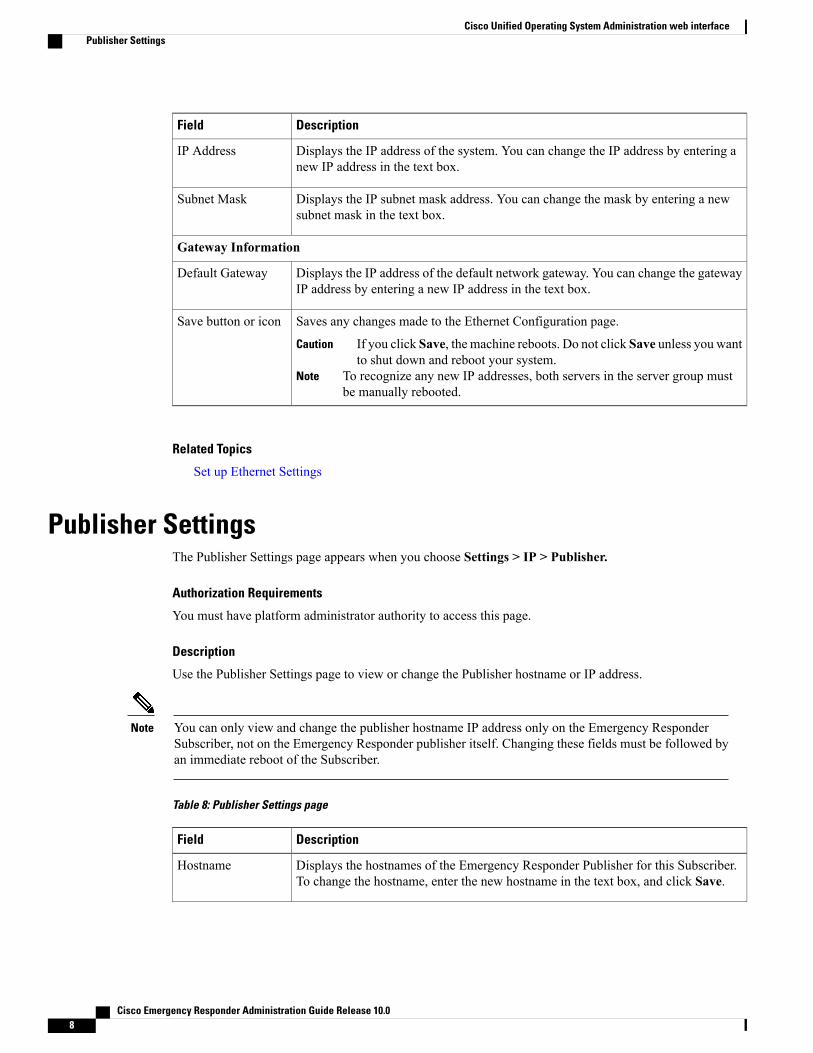
Displays the IP address of the system. You can change the IP address by entering anew IP address in the text box.
IP Address
Displays the IP subnet mask address. You can change the mask by entering a newsubnet mask in the text box.
Subnet Mask
Gateway Information
Displays the IP address of the default network gateway. You can change the gatewayIP address by entering a new IP address in the text box.
Default Gateway
Saves any changes made to the Ethernet Configuration page.
If you click Save, the machine reboots. Do not click Save unless you wantto shut down and reboot your system.
Caution
To recognize any new IP addresses, both servers in the server group mustbe manually rebooted.
Note
Save button or icon
Related Topics
Set up Ethernet Settings
Publisher SettingsThe Publisher Settings page appears when you choose Settings > IP > Publisher.
Authorization Requirements
You must have platform administrator authority to access this page.
Description
Use the Publisher Settings page to view or change the Publisher hostname or IP address.
You can only view and change the publisher hostname IP address only on the Emergency ResponderSubscriber, not on the Emergency Responder publisher itself. Changing these fields must be followed byan immediate reboot of the Subscriber.
Note
Table 8: Publisher Settings page
DescriptionField
Displays the hostnames of the Emergency Responder Publisher for this Subscriber.To change the hostname, enter the new hostname in the text box, and click Save.
Hostname
Cisco Emergency Responder Administration Guide Release 10.08
Cisco Unified Operating System Administration web interfacePublisher Settings

DescriptionField
Displays the IP address of the Emergency Responder Publisher for this Subscriber.To change the IP address, enter the IP address in the text box, and click Save.
IP Address
Saves the information in the Publisher Configuration Settings page.Save button or icon
Related Topics
Change IP Addresses for Emergency Responder servers
NTP Server ListThe NTP Server List page appears when you choose Settings > NTP Servers.
Authorization Requirements
You must have platform administrator authority to access this page.
Description
Use the NTP Server List page to add, modify, or delete an NTP server. You can only configure the NTP serversettings on the Publisher.
Ensure that the external NTP server is stratum 9 or higher (1 to 9).Note
Any change you make to the NTP servers can take up to five minutes to complete. Whenever you makeany change to the NTP servers, you must refresh the page to display the correct status.
Note
If you add, modify, or delete an NTP server, you must reboot both the Publisher and the Subscriber.Caution
The following table describes the NTP Server List page.
Table 9: NTP Server List page
DescriptionField
Displays how many configured NTP server were found.Status
NTP Server
Displays the hostnames or IP addresses of the configured NTP servers. To change ahostname or IP address, click it, enter the new hostname or IP address, and click Save.
Hostname or IPAddress field
Cisco Emergency Responder Administration Guide Release 10.0 9
Cisco Unified Operating System Administration web interfaceNTP Server List

DescriptionField
Adds a new NTP server. After you click Add New, enter the hostname of IP addressof the new NTP server and click Save.
Add New button oricon
Selects all NTP servers listed. When you click this button or icon, a check markappears in the boxes to the left of each NTP hostname or IP address and to the left ofthe Hostname or IP Address column heading.
The Select All button or icon is only visible if you have previously configuredone or more NTP servers.
Note
Select All button oricon
Deselects all NTP servers listed. When you click this button or icon, all check marksdisappear.
The Clear All button or icon is only visible if you have previously configuredone or more NTP servers.
Note
Clear All button oricon
Deletes the selected NTP server. To delete an NTP server, you must first select itfrom the list of NTP servers. Click the box to the left of the NTP server name to selectit. To select all listed NTP servers, click the box to the left of the Hostname or IPAddress column heading or click Select All.
The Delete Selected button or icon is only visible if you have previouslyconfigured one or more NTP servers.
Note
Delete Selectedbutton or icon
The following table describes the NTP Server Configuration page.
Table 10: NTP Server Configuration page
DescriptionField
Displays how many configured NTP server were found.Status
NTP Server Settings
Displays the hostnames or IP addresses of the configured NTP servers. To change ahostname or IP address, click it, enter the new hostname or IP address, and click Save.
Hostname or IPAddress field
Saves the information about the new NTP server.Save button or icon
Related Topics
Set up NTP servers
SMTP SettingsThe SMTP Settings page appears when you choose Settings > SMTP.
Cisco Emergency Responder Administration Guide Release 10.010
Cisco Unified Operating System Administration web interfaceSMTP Settings

Authorization Requirements
You must have platform administrator authority to access this page.
Description
Use the SMTP Settings page to manually configure the SMTP host.
The following table describes the SMTP Settings page.
Table 11: SMTP Settings page
DescriptionField
Displays the status of the SMTP Settings page.Status
SMTP Host
Enter the hostname or IP address of the SMTP server in the text box.Hostname or IP Address
Displays the status of the SMTP host server.Host Status
Saves changes made to the SMTP Settings page.Save button or icon
Related Topics
Set Up SNMPv2
Time SettingsThe Time Settings page appears when you choose Settings > Time.
Authorization Requirements
You must have platform administrator authority to access this page.
Description
Use the Time Settings page to manually configure the server time.
Before you can manually configure the server time, you must delete any NTP servers that you haveconfigured. See NTP Server List, on page 9 for more information.
Note
If you change the server time, you must reboot both the Publisher and the Subscriber.Caution
The following table describes the Time Settings page.
Cisco Emergency Responder Administration Guide Release 10.0 11
Cisco Unified Operating System Administration web interfaceTime Settings

Table 12: Time Settings page
DescriptionField
Allows you to set the month, day, year, hours, minutes, and seconds using thepull-down menus.
Date
Saves changes made to the Time Settings page.Save button or icon
Related Topics
NTP Server List, on page 9Set up NTP serversSet up Time Settings
Version SettingsThe Version Settings page appears when you choose Settings > Version.
Authorization Requirements
You must have platform administrator authority to access this page.
Description
Use the Version Settings page to restart or shutdown the system and to switch software versions.
You must have a different software version installed on the inactive partition to switch versions.Note
Initiating this action causes the system to restart and become temporarily unavailable.Caution
The following table describes the Version Settings page.
Table 13: Version Settings page
DescriptionField
Displays the current status.Status
Installed Versions
Displays the version running on the active partition.Active Version
Display the version on the inactive partition.Inactive Version
Restarts the system.Restart button or icon
Cisco Emergency Responder Administration Guide Release 10.012
Cisco Unified Operating System Administration web interfaceVersion Settings

DescriptionField
Shuts down the system.Shutdown button or icon
Actives the software version on the inactive partition.
The Switch Versions button or icon is only visible if there is a softwareversion installed on the inactive partition.
Note
Switch Versions button oricon
Related Topics
Manage software versions
Certificate ListThe Certificate List page appears when you choose Security > Certificate Management.
Authorization Requirements
You must have platform administrator authority to access this page.
Description
Use the Certificate List page to do the following:
• Search for existing certificates
• Generate a new certificates
• Upload a certificate
• Upload a CTL
• Generate a CSR
The following table describes the Certificate List page.
Table 14: Certificate List page
DescriptionField
Displays the current status.Status
Certificate List
Cisco Emergency Responder Administration Guide Release 10.0 13
Cisco Unified Operating System Administration web interfaceCertificate List

DescriptionField
Enter search criteria for the certificate lists you want to find.
To find all certificate lists by file name, select File Name from the pull-downmenu and click Find without entering any criteria.
To find all certificate lists by certificate name, select Certificate Name from thepull-down menu and click Find without entering any criteria.
To narrow your search:
• Select the search relationship (begins with, contains, and so on) from thepull-down menu, and enter the search string in the text box.
• To search on a combination of fields, click the Plus icon (+) to addadditional search parameters. Click theMinus icon (–) to remove searchparameters. ClickClear Filter to remove all additional search parameters.
• Use the Rows per Page pull-down menu to select how many rows aredisplayed per page.
When you have entered all of the search parameters, click Find.
If the search finds existing certificates, the information about the certificates(File Name, Certificate Name, and Certificate Type) displays in the CertificateList.
Click the File Name link to display the Certificate Configuration page. See Table20: Certificate Configuration page, on page 17 for information about theCertificate Configuration Page.
Find certificate list where
Allows you to generate a new certificate. When you click Generate New, theGenerate Certificate page appears. See Table 15: Generate Certificate page, onpage 15 for a description of the Generate Certificate page.
Generate New button oricon
Allows you to upload a certificate from a remote server. When you clickUploadCertificate, the Upload Certificate page appears. See Table 16: Upload Certificatepage, on page 15 for a description of the Upload Certificate page.
Upload Certificate buttonor icon
Allows you to upload a Certificate Trust List (CTL) from a remote server. Whenyou clickUpload CTL, the Upload Certificate Trust List page appears. See Table17: Upload CTL page, on page 15 for a description of the Upload CertificateTrust List page.
Upload CTL button oricon
Allows you to generate a new Certificate Signing Request (CSR). When youclick Generate CSR, the Generate Certificate Signing Request page appears.See Table 18: Generate CSR page, on page 16 for a description of the GenerateNew page.
Generate CSR button oricon
Allows you to download a CSR.When you clickDownloadCSR, the DownloadCertificate Signing Request page appears. See Table 19: Download CSR page,on page 16 for a description of the Download Certificate Signing Request page.
Download CSR button oricon
Cisco Emergency Responder Administration Guide Release 10.014
Cisco Unified Operating System Administration web interfaceCertificate List

The following table describes the Generate Certificate page.
Table 15: Generate Certificate page
DescriptionField
Displays the current status of the Generate Certificate page.Status
Generate Certificate
Allows you to choose a certificate name from the pull-down menu.Certificate Name
Generates a new certificate. You must first select a Certificate Name from thepull-down menu.
Generate New button oricon
Closes the Generate Certificate page.Close button or icon
The following table describes the Upload Certificate page.
Table 16: Upload Certificate page
DescriptionField
Displays the current status of the Upload Certificate page.Status
Upload Certificate
Use the pull-down menu to select the name of the certificate to upload.Certificate Name
Enter the name of the root certificate.Root Certificate
Use the Browse button to select the file to be uploaded.Upload File
Uploads the certificate file specified in the Upload Certificate section.Upload File button oricon
Closes the Update Certificate page.Close button or icon
The following table describes the Upload CTL page.
Table 17: Upload CTL page
DescriptionField
Displays the current status of the Upload CTL page.Status
Upload Certificate
Use the pull-down menu to select the name of the CTL file to upload.Certificate Name
Cisco Emergency Responder Administration Guide Release 10.0 15
Cisco Unified Operating System Administration web interfaceCertificate List

DescriptionField
Enter the name of the root certificate.Root Certificate
Use the Browse button to select the file to be uploaded.Upload File
Uploads the certificate file specified in the Upload Certificate Trust List section.Upload File button oricon
Closes the Update CTL page.Close button or icon
The following table describes the Generate CSR page.
Table 18: Generate CSR page
DescriptionField
Displays the current status of the Generate CSR page.Status
Generate Certificate Signing Request
Use the pull-down menu to select the name of the CTL file to generate.Certificate Name
Generates a new CSR.Generate CSR button oricon
Close the Generate CSR page.Close button or icon
The following table describes the Download CSR page.
Table 19: Download CSR page
DescriptionField
Displays the current status of the Download CSR page.Status
Download Certificate Signing Request
Use the pull-down menu to select the name of the CTL file to download.Certificate Name
Downloads the CSR specified in the Download Certificate Signing Requestsection.
Download CSR button oricon
Closes the Download CSR page.Close button or icon
The following table describes the Certificate Configuration page.
Cisco Emergency Responder Administration Guide Release 10.016
Cisco Unified Operating System Administration web interfaceCertificate List

Table 20: Certificate Configuration page
DescriptionField
Displays the current status of the Certificate Configuration page.Status
Displays the following information about the certificate:
• File Name
• Certificate Name
• Certificate Type
• Certificate Group
• Description
Certificate Settings
Displays the contents of the certificate file.Certificate File Data
Deletes the current certificate.Delete button or icon
Downloads the certificate to your local system.Download button or icon
Related Topics
Certificate management
Certificate MonitorThe Certificate Monitor page appears when you choose Security > Certificate Monitor.
Authorization Requirements
You must have platform administrator authority to access this page.
Description
Use the Certificate Monitor page to do the following:
• Specify the start time
• Specify the frequency
• Enable email notification and provide email addresses of those to be notified
The following table describes the Certificate Monitor page.
Cisco Emergency Responder Administration Guide Release 10.0 17
Cisco Unified Operating System Administration web interfaceCertificate Monitor

Table 21: Certificate Monitor page
DescriptionField
Displays the current status of the Certificate Monitor page.Status
Certificate Monitor Configuration
Enter the number of days before the certificate expires that you want to benotified.
Notification Start Time
Enter the notification frequency and click one of the radio buttons to indicatedays or hours.
Notification Frequency
Check the box to the enable email notification.
For the system to send notifications, you must configure an SMTPhost.
Note
Enable Email Notification
Enter the email addresses of those to be notified in the text box.Email ID
Saves the information entered on the Certificate Monitor page.Save button or icon
Related Topics
Certificate management
IPSec Policy ListThe IPSec Policy List page appears when you choose Security > IPSec Configuration.
Authorization Requirements
You must have platform administrator authority to access this page.
Description
Use the IPsec Policy List page to display existing IPsec policies, add an additional IPsec policy, or modifyan existing IPsec policy.
The following table describes the IPsec Policy List page.
Table 22: IPSec Policy List page
DescriptionField
Displays the current status of the IPsec Policy List page.Status
Displays the currently configured IPsec policies. Click on the Policy Name linkto IPsec Policy Configuration page for that policy.
IPSec Policy List
Cisco Emergency Responder Administration Guide Release 10.018
Cisco Unified Operating System Administration web interfaceIPSec Policy List
DescriptionField
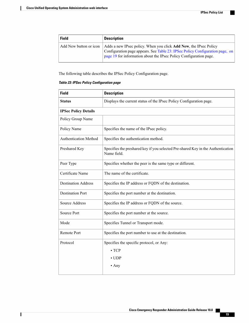
Adds a new IPsec policy. When you click Add New, the IPsec PolicyConfiguration page appears. See Table 23: IPSec Policy Configuration page, onpage 19 for information about the IPsec Policy Configuration page.
Add New button or icon
The following table describes the IPSec Policy Configuration page.
Table 23: IPSec Policy Configuration page
DescriptionField
Displays the current status of the IPsec Policy Configuration page.Status
IPSec Policy Details
Policy Group Name
Specifies the name of the IPsec policy.Policy Name
Specifies the authentication method.Authentication Method
Specifies the preshared key if you selected Pre-shared Key in the AuthenticationName field.
Preshared Key
Specifies whether the peer is the same type or different.Peer Type
The name of the certificate.Certificate Name
Specifies the IP address or FQDN of the destination.Destination Address
Specifies the port number at the destination.Destination Port
Specifies the IP address or FQDN of the source.Source Address
Specifies the port number at the source.Source Port
Specifies Tunnel or Transport mode.Mode
Specifies the port number to use at the destination.Remote Port
Specifies the specific protocol, or Any:
• TCP
• UDP
• Any
Protocol
Cisco Emergency Responder Administration Guide Release 10.0 19
Cisco Unified Operating System Administration web interfaceIPSec Policy List

DescriptionField
From the drop-down list, choose the encryption algorithm. Choices include:
• DES
• 3DES
Encryption Algorithm
Specifies the hash algorithm:
• SHA1—Hash algorithm that is used in phase 1 IKE negotiation.
• MD5—Hash algorithm that is used in phase 1 IKE negotiation.
Hash Algorithm
From the drop-down list, choose the ESP algorithm. Choices include:
• NULL_ENC
• DES
• 3DES
• BLOWFISH
• RIJNDAEL
ESP Algorithm
Phase 1 DH Group
Specifies the lifetime for phase One, IKE negotiation, in seconds.Phase One Life Time
From the drop-down list, choose the phase One DH value. Choices include: 2,1, 5, 14, 16, 17, and 18.
Phase One DH
Phase 1 DH Group
Specifies the lifetime for phase Two, IKE negotiation, in seconds.Phase Two Life Time
From the drop-down list, choose the phase Two DH value. Choices include: 2,1, 5, 14, 16, 17, and 18.
Phase Two DH
IPSec Policy Configuration
Check the check box to enable the policy.Enable Policy
Saves the changes made to the IPsec Policy List page.Save button or icon
Related Topics
IPsec management
Cisco Emergency Responder Administration Guide Release 10.020
Cisco Unified Operating System Administration web interfaceIPSec Policy List

Software Installation/UpgradeThe Software Installation/Upgrade page appears when you choose Software Upgrades > Install/Upgrade.
Authorization Requirements
You must have platform administrator authority to access this page.
Description
Use the Software Installation/Upgrade page to install or upgrade software from a DVD/CD or from a filesystem on a remote server.
The following table describes the Software Installation/Upgrade page.
Table 24: Software Installation/Upgrade page
DescriptionField
Displays the current status of the Software Installation/Upgrade page.Status
Software Location
Pull-down menu used to specify the source for the installation/upgrade. Options areDVD/CD or Remote Filesystem.
Source
The name of the directory containing the files.
If the upgrade file is on a Linux or Unix server, you must enter a forwardslash at the beginning of the directory path that you want to specify. Forexample, if the upgrade file is in the patches directory, you must enter/patches. If the upgrade file is on aWindows server, check with your systemadministrator for the correct directory path.
Note
Directory
The hostname or IP address of the remote server from which the software isdownloaded.
Server
The name of a user who is configured on the remote server.User Name
Password that is configured for this user on the remote server.User Password
Pull-down menu used to specify which transfer protocol to use. Options are ftp orsftp.
These options are available only if you selected Remote Filesystem fromthe Source pull-down menu. If you selectedDVD/CD, this pull-down menuis grayed out.
Note
Transfer Protocol
Cancels the installation or upgrade procedure.Cancel Install buttonor icon
Continues with the installation or upgrade procedure.Next button or icon
Cisco Emergency Responder Administration Guide Release 10.0 21
Cisco Unified Operating System Administration web interfaceSoftware Installation/Upgrade
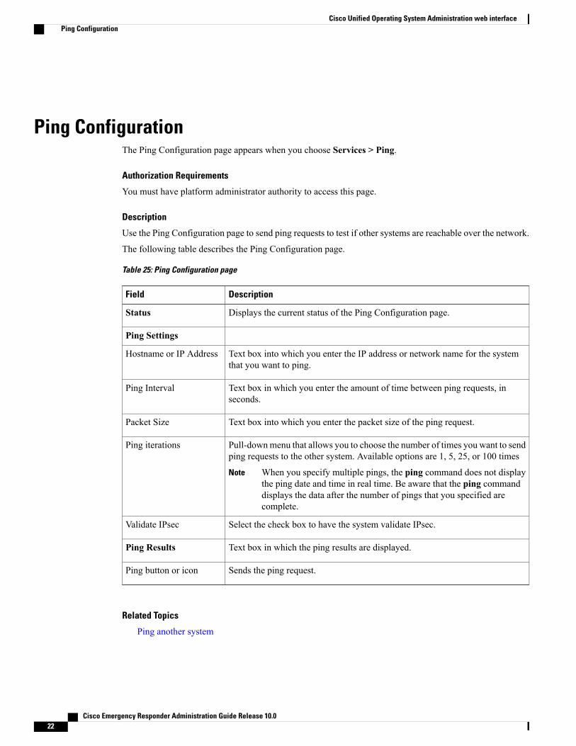
Ping ConfigurationThe Ping Configuration page appears when you choose Services > Ping.
Authorization Requirements
You must have platform administrator authority to access this page.
Description
Use the Ping Configuration page to send ping requests to test if other systems are reachable over the network.
The following table describes the Ping Configuration page.
Table 25: Ping Configuration page
DescriptionField
Displays the current status of the Ping Configuration page.Status
Ping Settings
Text box into which you enter the IP address or network name for the systemthat you want to ping.
Hostname or IP Address
Text box in which you enter the amount of time between ping requests, inseconds.
Ping Interval
Text box into which you enter the packet size of the ping request.Packet Size
Pull-downmenu that allows you to choose the number of times you want to sendping requests to the other system. Available options are 1, 5, 25, or 100 times
When you specify multiple pings, the ping command does not displaythe ping date and time in real time. Be aware that the ping commanddisplays the data after the number of pings that you specified arecomplete.
Note
Ping iterations
Select the check box to have the system validate IPsec.Validate IPsec
Text box in which the ping results are displayed.Ping Results
Sends the ping request.Ping button or icon
Related Topics
Ping another system
Cisco Emergency Responder Administration Guide Release 10.022
Cisco Unified Operating System Administration web interfacePing Configuration

Remote Access ConfigurationThe Remote Access Configuration page appears when you choose Services > Remote Support.
Authorization Requirements
You must have platform administrator authority to access this page.
Description
Use the Remote Access Configuration page to set up a remote account that Cisco support personnel can useto access the system for a specified period of time. If the account duration limit expires, Cisco support cannot access the remote support account.
When you establish a remote account, the system generates a pass phrase.
Follow this procedure to complete the remote account setup:
1 Call Cisco support and provide them with the remote support account name and pass phrase.
2 Cisco support enters the pass phrase into a decoder program that generates a password from the passphrase.
3 Cisco support logs into the remote support account on the customer system by using the decoded password.
If you have not already created a remote account, when you navigate to the Remote Access Configurationpage you can create a new account.
The following table describes the Remote Access Configuration page.
Table 26: Remote Access Configuration page
DescriptionField
Displays the current status of the Remote Access Configuration page.Status
Remote Access Account Information
Name for the new remote account. Account names must be at least six-characterslong and consist of all lowercase, alphabetic characters
Account Name
The amount of time that the remote account exists, in days.Account Duration
Creates a new remote account. You must provide the Account Name and AccountDuration before you click Add. Remote Access Configuration page redisplays. SeeTable 27: Remote Access Configuration page , on page 24 for a description of thefields on the Remote Access Configuration page.
Save button or icon
Deletes the currently configured remote account.
The Delete button or icon is only visible if there is an existing remote account.Note
Delete button or icon
Cisco Emergency Responder Administration Guide Release 10.0 23
Cisco Unified Operating System Administration web interfaceRemote Access Configuration

If you have already created a remote account, when you navigate to the Remote Access Configuration pageyou view and delete the remote account.
The following table describes the Remote Access Configuration page.
Table 27: Remote Access Configuration page
DescriptionField
Remote Access Account Information
Displays the name of the remote support account.Account Name
Displays the date and time when access to the remote account expires.Expiration
Displays the generated pass phrase.Passphrase
Indicates the version of the decoder in use.Decode Version
Deletes the remote access account information.Delete button or icon
Related Topics
Set up remote support
Cisco Emergency Responder Administration Guide Release 10.024
Cisco Unified Operating System Administration web interfaceRemote Access Configuration