Cisco UCS C22 M3 High-Density Small Form Factor Rack...
62
CISCO SYSTEMS PUBLICATION HISTORY 170 WEST TASMAN DR. SAN JOSE, CA, 95134 REV A.1 NOVEMBER 2, 2012 WWW.CISCO.COM Cisco UCS C22 M3 High-Density Rack-Mount Server (Small Form Factor Hard Disk Drive Model)
Transcript of Cisco UCS C22 M3 High-Density Small Form Factor Rack...
CISCO SYSTEMS PUBLICATION HISTORY 170 WEST TASMAN DR. SAN JOSE, CA, 95134 REV A.1 NOVEMBER 2, 2012 WWW.CISCO.COM
Cisco UCS C22 M3High-Density Rack-Mount Server (Small Form Factor Hard Disk Drive Model)
Cisco UCS C22 M3 High-Density SFF Rack-Mount Server 2
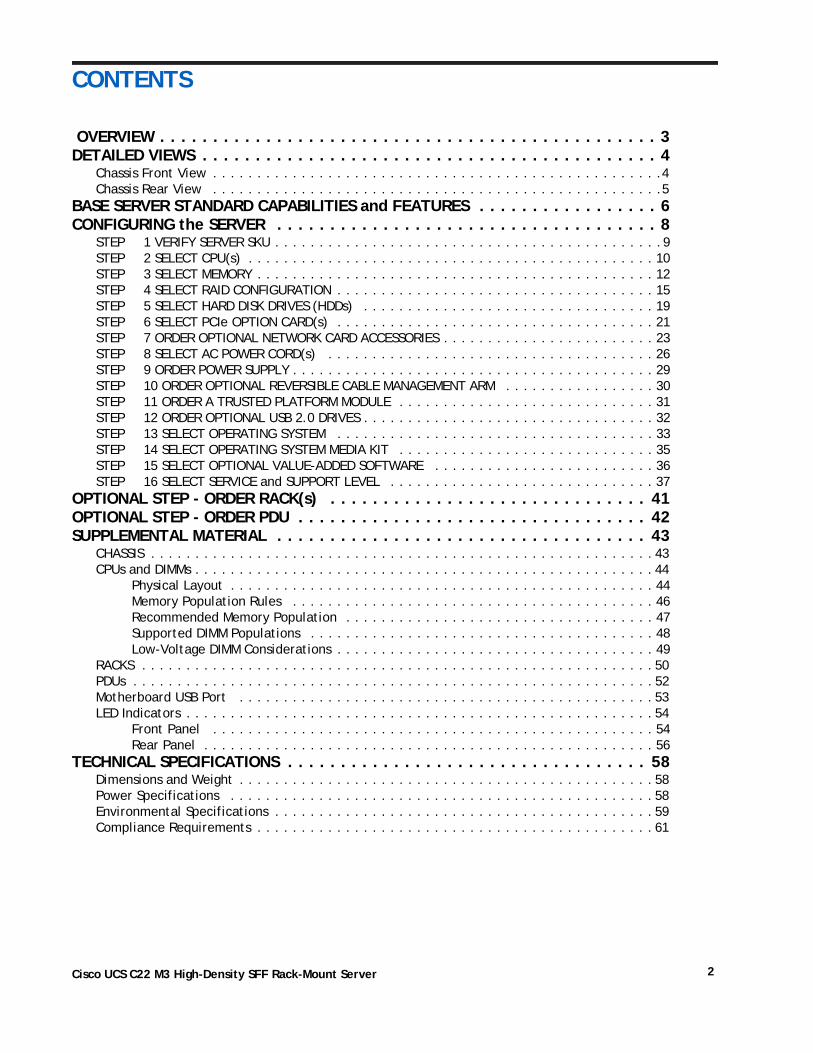
CONTENTS
OVERVIEW . . . . . . . . . . . . . . . . . . . . . . . . . . . . . . . . . . . . . . . . . . . . . . . 3DETAILED VIEWS . . . . . . . . . . . . . . . . . . . . . . . . . . . . . . . . . . . . . . . . . . . 4
Chassis Front View . . . . . . . . . . . . . . . . . . . . . . . . . . . . . . . . . . . . . . . . . . . . . . . . . . .4Chassis Rear View . . . . . . . . . . . . . . . . . . . . . . . . . . . . . . . . . . . . . . . . . . . . . . . . . . .5
BASE SERVER STANDARD CAPABILITIES and FEATURES . . . . . . . . . . . . . . . . . 6CONFIGURING the SERVER . . . . . . . . . . . . . . . . . . . . . . . . . . . . . . . . . . . . 8
STEP 1 VERIFY SERVER SKU . . . . . . . . . . . . . . . . . . . . . . . . . . . . . . . . . . . . . . . . . . . .9STEP 2 SELECT CPU(s) . . . . . . . . . . . . . . . . . . . . . . . . . . . . . . . . . . . . . . . . . . . . . . 10STEP 3 SELECT MEMORY . . . . . . . . . . . . . . . . . . . . . . . . . . . . . . . . . . . . . . . . . . . . . 12STEP 4 SELECT RAID CONFIGURATION . . . . . . . . . . . . . . . . . . . . . . . . . . . . . . . . . . . . 15STEP 5 SELECT HARD DISK DRIVES (HDDs) . . . . . . . . . . . . . . . . . . . . . . . . . . . . . . . . . 19STEP 6 SELECT PCIe OPTION CARD(s) . . . . . . . . . . . . . . . . . . . . . . . . . . . . . . . . . . . . 21STEP 7 ORDER OPTIONAL NETWORK CARD ACCESSORIES . . . . . . . . . . . . . . . . . . . . . . . . 23STEP 8 SELECT AC POWER CORD(s) . . . . . . . . . . . . . . . . . . . . . . . . . . . . . . . . . . . . . 26STEP 9 ORDER POWER SUPPLY . . . . . . . . . . . . . . . . . . . . . . . . . . . . . . . . . . . . . . . . . 29STEP 10 ORDER OPTIONAL REVERSIBLE CABLE MANAGEMENT ARM . . . . . . . . . . . . . . . . . 30STEP 11 ORDER A TRUSTED PLATFORM MODULE . . . . . . . . . . . . . . . . . . . . . . . . . . . . . 31STEP 12 ORDER OPTIONAL USB 2.0 DRIVES . . . . . . . . . . . . . . . . . . . . . . . . . . . . . . . . . 32STEP 13 SELECT OPERATING SYSTEM . . . . . . . . . . . . . . . . . . . . . . . . . . . . . . . . . . . . 33STEP 14 SELECT OPERATING SYSTEM MEDIA KIT . . . . . . . . . . . . . . . . . . . . . . . . . . . . . 35STEP 15 SELECT OPTIONAL VALUE-ADDED SOFTWARE . . . . . . . . . . . . . . . . . . . . . . . . . 36STEP 16 SELECT SERVICE and SUPPORT LEVEL . . . . . . . . . . . . . . . . . . . . . . . . . . . . . . 37
OPTIONAL STEP - ORDER RACK(s) . . . . . . . . . . . . . . . . . . . . . . . . . . . . . . 41OPTIONAL STEP - ORDER PDU . . . . . . . . . . . . . . . . . . . . . . . . . . . . . . . . . 42SUPPLEMENTAL MATERIAL . . . . . . . . . . . . . . . . . . . . . . . . . . . . . . . . . . . 43
CHASSIS . . . . . . . . . . . . . . . . . . . . . . . . . . . . . . . . . . . . . . . . . . . . . . . . . . . . . . . . . 43CPUs and DIMMs . . . . . . . . . . . . . . . . . . . . . . . . . . . . . . . . . . . . . . . . . . . . . . . . . . . . 44
Physical Layout . . . . . . . . . . . . . . . . . . . . . . . . . . . . . . . . . . . . . . . . . . . . . . . . 44Memory Population Rules . . . . . . . . . . . . . . . . . . . . . . . . . . . . . . . . . . . . . . . . . 46Recommended Memory Population . . . . . . . . . . . . . . . . . . . . . . . . . . . . . . . . . . . 47Supported DIMM Populations . . . . . . . . . . . . . . . . . . . . . . . . . . . . . . . . . . . . . . . 48Low-Voltage DIMM Considerations . . . . . . . . . . . . . . . . . . . . . . . . . . . . . . . . . . . . 49
RACKS . . . . . . . . . . . . . . . . . . . . . . . . . . . . . . . . . . . . . . . . . . . . . . . . . . . . . . . . . . 50PDUs . . . . . . . . . . . . . . . . . . . . . . . . . . . . . . . . . . . . . . . . . . . . . . . . . . . . . . . . . . . 52Motherboard USB Port . . . . . . . . . . . . . . . . . . . . . . . . . . . . . . . . . . . . . . . . . . . . . . . 53LED Indicators . . . . . . . . . . . . . . . . . . . . . . . . . . . . . . . . . . . . . . . . . . . . . . . . . . . . . 54
Front Panel . . . . . . . . . . . . . . . . . . . . . . . . . . . . . . . . . . . . . . . . . . . . . . . . . . 54Rear Panel . . . . . . . . . . . . . . . . . . . . . . . . . . . . . . . . . . . . . . . . . . . . . . . . . . . 56
TECHNICAL SPECIFICATIONS . . . . . . . . . . . . . . . . . . . . . . . . . . . . . . . . . . 58Dimensions and Weight . . . . . . . . . . . . . . . . . . . . . . . . . . . . . . . . . . . . . . . . . . . . . . . 58Power Specifications . . . . . . . . . . . . . . . . . . . . . . . . . . . . . . . . . . . . . . . . . . . . . . . . 58Environmental Specifications . . . . . . . . . . . . . . . . . . . . . . . . . . . . . . . . . . . . . . . . . . . 59Compliance Requirements . . . . . . . . . . . . . . . . . . . . . . . . . . . . . . . . . . . . . . . . . . . . . 61
OVERVIEW
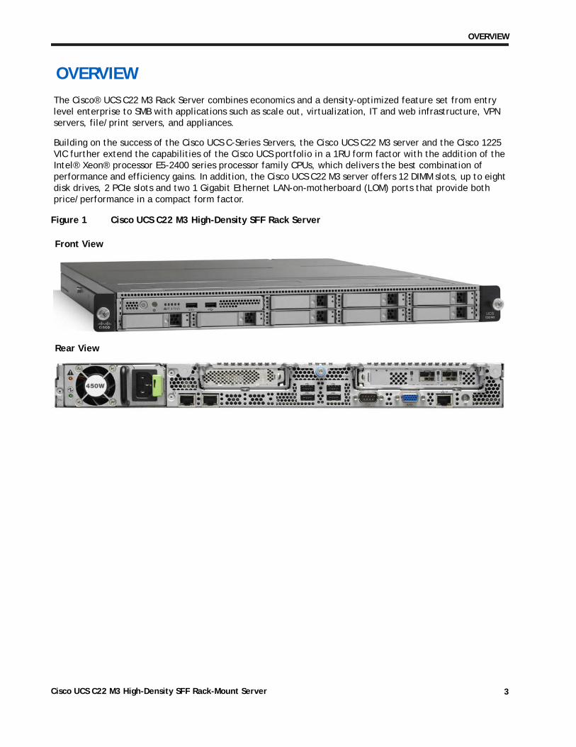
OVERVIEWThe Cisco® UCS C22 M3 Rack Server combines economics and a density-optimized feature set from entry level enterprise to SMB with applications such as scale out, virtualization, IT and web infrastructure, VPN servers, file/print servers, and appliances.
Building on the success of the Cisco UCS C-Series Servers, the Cisco UCS C22 M3 server and the Cisco 1225 VIC further extend the capabilities of the Cisco UCS portfolio in a 1RU form factor with the addition of the Intel® Xeon® processor E5-2400 series processor family CPUs, which delivers the best combination of performance and efficiency gains. In addition, the Cisco UCS C22 M3 server offers 12 DIMM slots, up to eight disk drives, 2 PCIe slots and two 1 Gigabit Ethernet LAN-on-motherboard (LOM) ports that provide both price/performance in a compact form factor.
Figure 1 Cisco UCS C22 M3 High-Density SFF Rack Server
Front View
Rear View
Cisco UCS C22 M3 High-Density SFF Rack-Mount Server 3
DETAILED VIEWS
DETAILED VIEWS
Chassis Front View
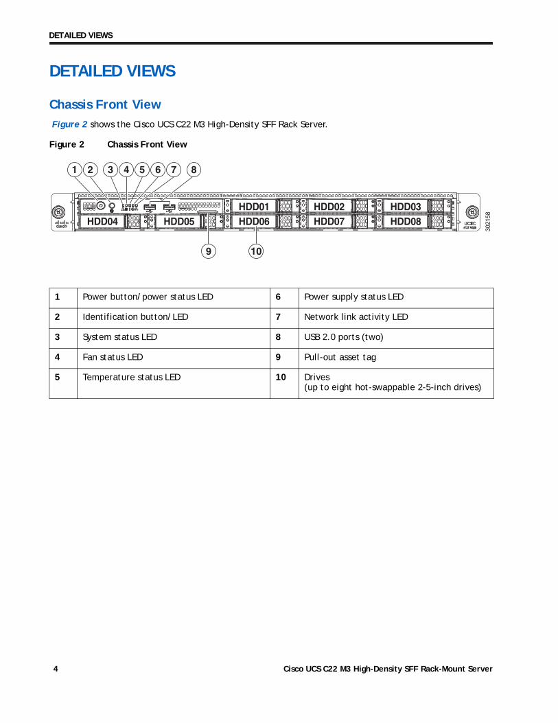
Figure 2 shows the Cisco UCS C22 M3 High-Density SFF Rack Server.
Figure 2 Chassis Front View
1 Power button/power status LED 6 Power supply status LED
2 Identification button/LED 7 Network link activity LED
3 System status LED 8 USB 2.0 ports (two)
4 Fan status LED 9 Pull-out asset tag
5 Temperature status LED 10 Drives (up to eight hot-swappable 2-5-inch drives)
HDD06HDD01
HDD07HDD02
HDD08HDD03
HDD04HDD04HDD04 HDD05HDD05HDD05
1 2 3 4
9 10
5 6 7 8
3021
58
Cisco UCS C22 M3 High-Density SFF Rack-Mount Server4
DETAILED VIEWS
Chassis Rear View
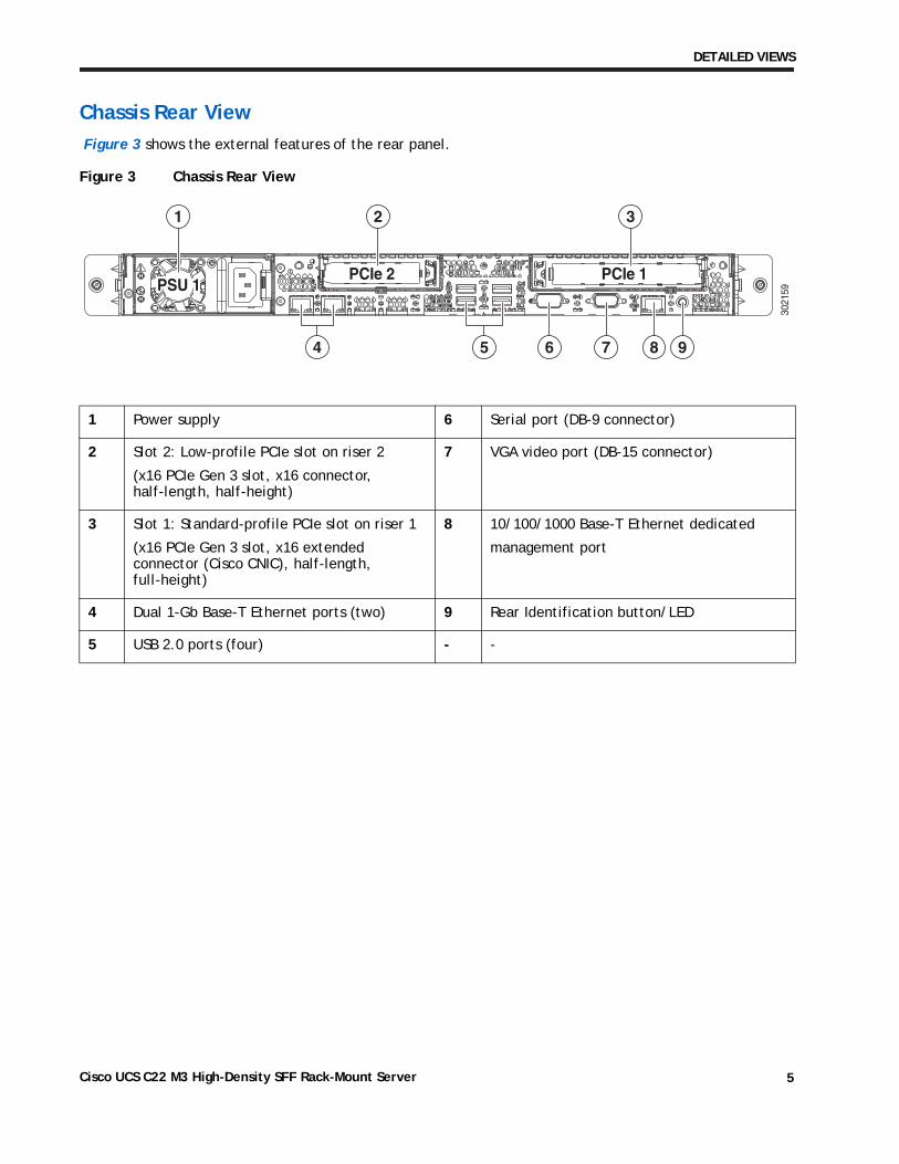
Figure 3 shows the external features of the rear panel.
Figure 3 Chassis Rear View
1 Power supply 6 Serial port (DB-9 connector)
2 Slot 2: Low-profile PCIe slot on riser 2
(x16 PCIe Gen 3 slot, x16 connector, half-length, half-height)
7 VGA video port (DB-15 connector)
3 Slot 1: Standard-profile PCIe slot on riser 1
(x16 PCIe Gen 3 slot, x16 extended connector (Cisco CNIC), half-length, full-height)
8 10/100/1000 Base-T Ethernet dedicated
management port
4 Dual 1-Gb Base-T Ethernet ports (two) 9 Rear Identification button/LED
5 USB 2.0 ports (four) - -
PSU 1PSU 1PSU 1PCIe 2PCIe 2PCIe 2 PCIe 1PCIe 1PCIe 1
1 2 3
654 7 8 9
3021
59
Cisco UCS C22 M3 High-Density SFF Rack-Mount Server 5
BASE SERVER STANDARD CAPABILITIES and FEATURES
BASE SERVER STANDARD CAPABILITIES and FEATURESTable 1 lists the capabilities and features of the base server. Details about how to configure the server for a particular feature or capability (for example, number of processors, disk drives, or amount of memory) are provided in CONFIGURING the SERVER, page 8.
Table 1 Capabilities and Features
Capability/Feature Description
Chassis Single rack unit (1RU) chassis
CPU One or two Intel® Xeon E5-2400 series processor family CPUs
Chipset Intel C600 chipset
Memory 12 DIMM slots
NIC Embedded dual-port Intel I350 PCIe-based Gigabit Ethernet controller
Expansion slots Two riser cards with one PCIe card slot in each riser
■ Riser 1 (controlled by CPU 1)
• One x16 PCIe Gen 3 slot, x16 extended connector (Cisco CNIC), half-length, full-height, with NCSI1 and Cisco CNIC2 support. The Cisco 1225 virtual interface card requires an NCSI slot.
■ Riser 2 (controlled by CPU 2)
• One x16 PCIe Gen 3 slot, x16 connector, half-length, half-height, no NCSI support
Storage controller The following RAID options are available:
■ Software RAID, utilizing the SAS controller built into the C600 chipset and LSI Mega software RAID (MegaSR). This implementation of RAID does not consume a PCIe slot.
■ Plug-in RAID controller cards (these cards consume PCIe slots)
• LSI MegaRAID 9265CV-8i (with 1GB Transportable Memory Module (TMM) data cache and SuperCap for data cache power backup)
• LSI MegaRAID 9240-8i
• LSI MegaRAID 9220-8i
• LSI MegaRAID 9220-4i
Internal storage devices ■ Up to eight 2.5-inch SAS or SATA hot-swappable hard disk drives (HDDs)
■ One connector on the motherboard that can accommodate a USB 2.0 drive. You can order an 8 GB drive for this connector and use it as a hypervisor or license dongle. The 8 GB USB drive comes blank.
External Storage Devices
■ A 16 GB USB drive (if ordered) comes as a separate item in the shipping box and contains preloaded drivers and utilities. You can move the 16 GB drive from one server to another an using external USB 2.0 connector in order to install the drivers and utilities onto multiple servers.
Cisco UCS C22 M3 High-Density SFF Rack-Mount Server6
BASE SERVER STANDARD CAPABILITIES and FEATURES
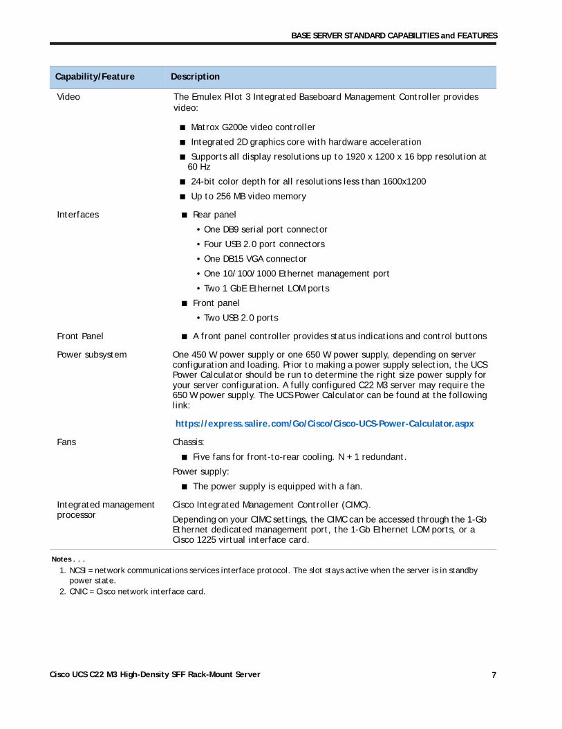
Video The Emulex Pilot 3 Integrated Baseboard Management Controller provides video:
■ Matrox G200e video controller
■ Integrated 2D graphics core with hardware acceleration
■ Supports all display resolutions up to 1920 x 1200 x 16 bpp resolution at 60 Hz
■ 24-bit color depth for all resolutions less than 1600x1200
■ Up to 256 MB video memory
Interfaces ■ Rear panel
• One DB9 serial port connector
• Four USB 2.0 port connectors
• One DB15 VGA connector
• One 10/100/1000 Ethernet management port
• Two 1 GbE Ethernet LOM ports
■ Front panel
• Two USB 2.0 ports
Front Panel ■ A front panel controller provides status indications and control buttons
Power subsystem One 450 W power supply or one 650 W power supply, depending on server configuration and loading. Prior to making a power supply selection, the UCS Power Calculator should be run to determine the right size power supply for your server configuration. A fully configured C22 M3 server may require the 650 W power supply. The UCS Power Calculator can be found at the following link:
https://express.salire.com/Go/Cisco/Cisco-UCS-Power-Calculator.aspx
Fans Chassis:
■ Five fans for front-to-rear cooling. N + 1 redundant.
Power supply:
■ The power supply is equipped with a fan.
Integrated management processor
Cisco Integrated Management Controller (CIMC).
Depending on your CIMC settings, the CIMC can be accessed through the 1-Gb Ethernet dedicated management port, the 1-Gb Ethernet LOM ports, or a Cisco 1225 virtual interface card.
Notes . . .
1. NCSI = network communications services interface protocol. The slot stays active when the server is in standby power state.
2. CNIC = Cisco network interface card.
Capability/Feature Description
Cisco UCS C22 M3 High-Density SFF Rack-Mount Server 7
CONFIGURING the SERVER
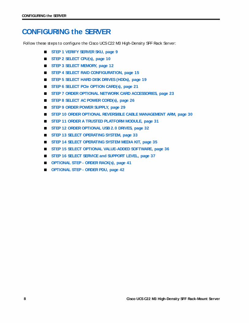
CONFIGURING the SERVERFollow these steps to configure the Cisco UCS C22 M3 High-Density SFF Rack Server:
■ STEP 1 VERIFY SERVER SKU, page 9
■ STEP 2 SELECT CPU(s), page 10
■ STEP 3 SELECT MEMORY, page 12
■ STEP 4 SELECT RAID CONFIGURATION, page 15
■ STEP 5 SELECT HARD DISK DRIVES (HDDs), page 19
■ STEP 6 SELECT PCIe OPTION CARD(s), page 21
■ STEP 7 ORDER OPTIONAL NETWORK CARD ACCESSORIES, page 23
■ STEP 8 SELECT AC POWER CORD(s), page 26
■ STEP 9 ORDER POWER SUPPLY, page 29
■ STEP 10 ORDER OPTIONAL REVERSIBLE CABLE MANAGEMENT ARM, page 30
■ STEP 11 ORDER A TRUSTED PLATFORM MODULE, page 31
■ STEP 12 ORDER OPTIONAL USB 2.0 DRIVES, page 32
■ STEP 13 SELECT OPERATING SYSTEM, page 33
■ STEP 14 SELECT OPERATING SYSTEM MEDIA KIT, page 35
■ STEP 15 SELECT OPTIONAL VALUE-ADDED SOFTWARE, page 36
■ STEP 16 SELECT SERVICE and SUPPORT LEVEL, page 37
■ OPTIONAL STEP - ORDER RACK(s), page 41
■ OPTIONAL STEP - ORDER PDU, page 42
Cisco UCS C22 M3 High-Density SFF Rack-Mount Server8
CONFIGURING the SERVER
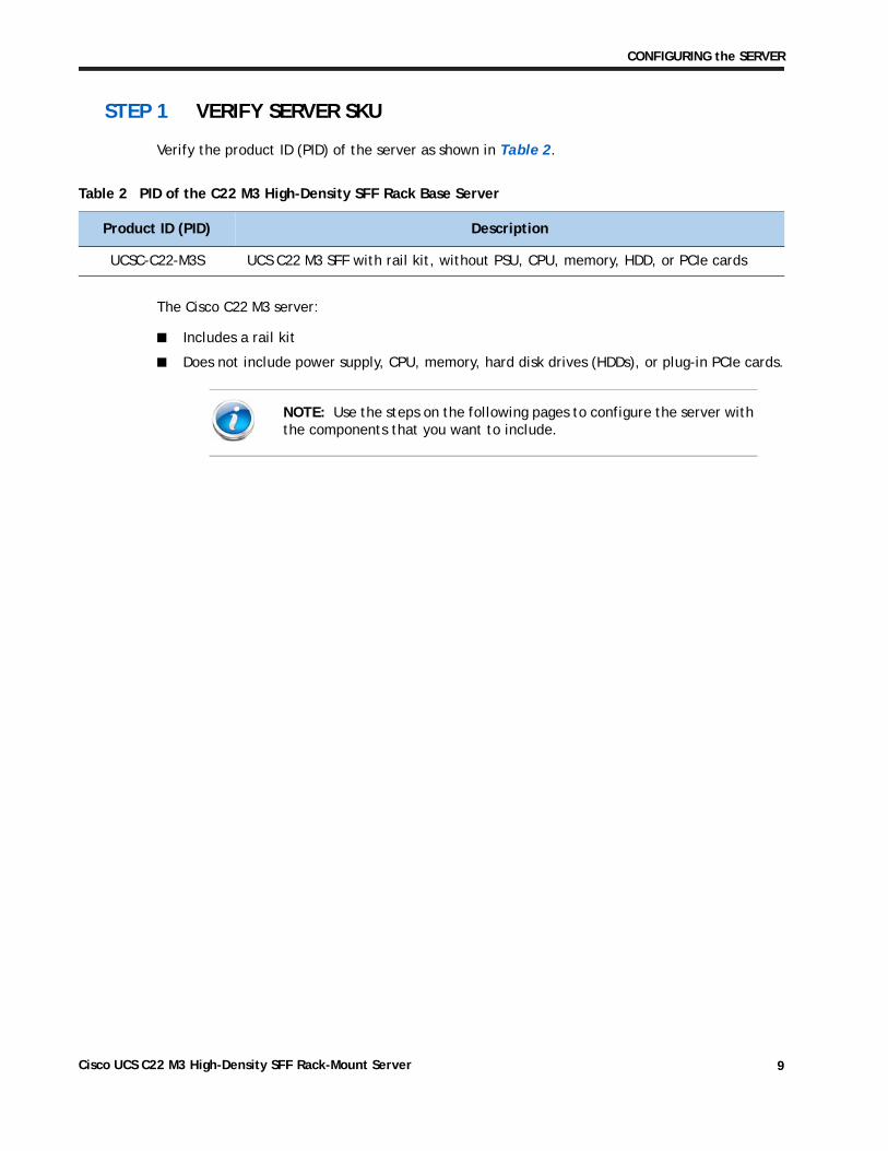
STEP 1 VERIFY SERVER SKU
Verify the product ID (PID) of the server as shown in Table 2.
The Cisco C22 M3 server:
■ Includes a rail kit
■ Does not include power supply, CPU, memory, hard disk drives (HDDs), or plug-in PCIe cards.
Table 2 PID of the C22 M3 High-Density SFF Rack Base Server
Product ID (PID) Description
UCSC-C22-M3S UCS C22 M3 SFF with rail kit, without PSU, CPU, memory, HDD, or PCIe cards
NOTE: Use the steps on the following pages to configure the server with the components that you want to include.
Cisco UCS C22 M3 High-Density SFF Rack-Mount Server 9
CONFIGURING the SERVER
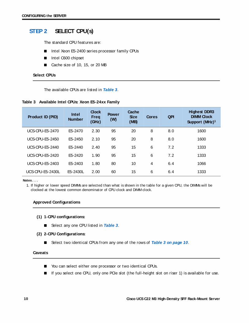
STEP 2 SELECT CPU(s)
The standard CPU features are:
■ Intel Xeon E5-2400 series processor family CPUs
■ Intel C600 chipset
■ Cache size of 10, 15, or 20 MB
Select CPUs
The available CPUs are listed in Table 3.
Approved Configurations
(1) 1-CPU configurations:
■ Select any one CPU listed in Table 3.
(2) 2-CPU Configurations:
■ Select two identical CPUs from any one of the rows of Table 3 on page 10.
Caveats
■ You can select either one processor or two identical CPUs.
■ If you select one CPU, only one PCIe slot (the full-height slot on riser 1) is available for use.
Table 3 Available Intel CPUs: Xeon E5-24xx Family
Product ID (PID)Intel
Number
Clock Freq(GHz)
Power (W)
Cache Size (MB)
Cores QPIHighest DDR3 DIMM Clock
Support (MHz)1
Notes . . .
1. If higher or lower speed DIMMs are selected than what is shown in the table for a given CPU, the DIMMs will be clocked at the lowest common denominator of CPU clock and DIMM clock.
UCS-CPU-E5-2470 E5-2470 2.30 95 20 8 8.0 1600
UCS-CPU-E5-2450 E5-2450 2.10 95 20 8 8.0 1600
UCS-CPU-E5-2440 E5-2440 2.40 95 15 6 7.2 1333
UCS-CPU-E5-2420 E5-2420 1.90 95 15 6 7.2 1333
UCS-CPU-E5-2403 E5-2403 1.80 80 10 4 6.4 1066
UCS-CPU-E5-2430L E5-2430L 2.00 60 15 6 6.4 1333
Cisco UCS C22 M3 High-Density SFF Rack-Mount Server10
CONFIGURING the SERVER
■ For optimal performance, select DIMMs with the highest clock speed for a given processor (see Table 3 on page 10). If you select DIMMs whose speeds are lower or higher than that shown in the tables, suboptimal performance will result.
Cisco UCS C22 M3 High-Density SFF Rack-Mount Server 11
CONFIGURING the SERVER
STEP 3 SELECT MEMORY
The standard memory features are:
■ DIMMs
— Clock speed: 1333 or 1600 MHz
— Ranks per DIMM: 1 or 2
— Operational voltage: dual voltage capable (1.5 V or 1.35 V)
— Registered ECC DDR3 DIMMS (RDIMMS)
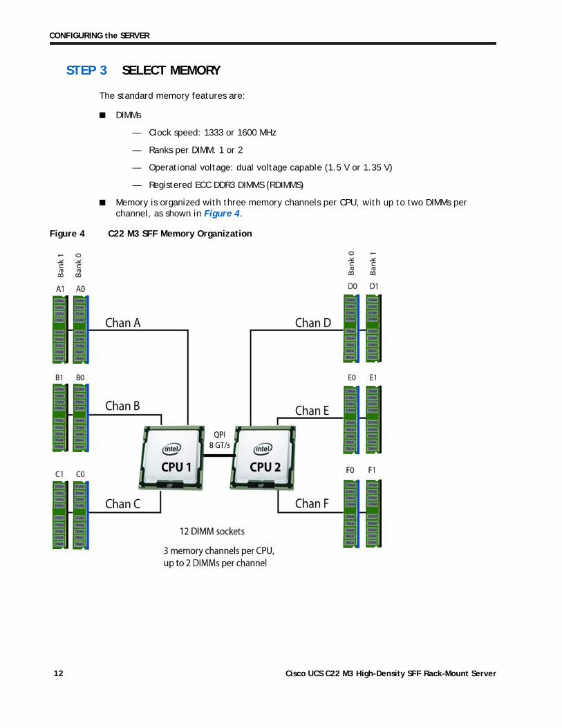
■ Memory is organized with three memory channels per CPU, with up to two DIMMs per channel, as shown in Figure 4.
Figure 4 C22 M3 SFF Memory Organization
Cisco UCS C22 M3 High-Density SFF Rack-Mount Server12
CONFIGURING the SERVER
Select DIMMs
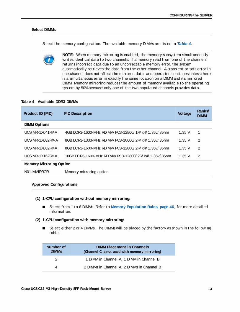
Select the memory configuration. The available memory DIMMs are listed in Table 4.
Approved Configurations
(1) 1-CPU configuration without memory mirroring:
■ Select from 1 to 6 DIMMs. Refer to Memory Population Rules, page 46, for more detailed information.
(2) 1-CPU configuration with memory mirroring:
■ Select either 2 or 4 DIMMs. The DIMMs will be placed by the factory as shown in the following table:
NOTE: When memory mirroring is enabled, the memory subsystem simultaneously writes identical data to two channels. If a memory read from one of the channels returns incorrect data due to an uncorrectable memory error, the system automatically retrieves the data from the other channel. A transient or soft error in one channel does not affect the mirrored data, and operation continues unless there is a simultaneous error in exactly the same location on a DIMM and its mirrored DIMM. Memory mirroring reduces the amount of memory available to the operating system by 50% because only one of the two populated channels provides data.
Table 4 Available DDR3 DIMMs
Product ID (PID) PID Description VoltageRanks/DIMM
DIMM Options
UCS-MR-1X041RY-A 4GB DDR3-1600-MHz RDIMM/PC3-12800/1R/x4/1.35v/35nm 1.35 V 1
UCS-MR-1X082RX-A 8GB DDR3-1333-MHz RDIMM/PC3-10600/2R/x4/1.35v/35nm 1.35 V 2
UCS-MR-1X082RY-A 8GB DDR3-1600-MHz RDIMM/PC3-12800/2R/x4/1.35v/35nm 1.35 V 2
UCS-MR-1X162RY-A 16GB DDR3-1600-MHz RDIMM/PC3-12800/2R/x4/1.35v/35nm 1.35 V 2
Memory Mirroring Option
N01-MMIRROR Memory mirroring option
Number of DIMMs
DIMM Placement in Channels(Channel C is not used with memory mirroring)
2 1 DIMM in Channel A, 1 DIMM in Channel B
4 2 DIMMs in Channel A, 2 DIMMs in Channel B
Cisco UCS C22 M3 High-Density SFF Rack-Mount Server 13
CONFIGURING the SERVER
■ Select the memory mirroring option (N01-MMIRROR) as shown in Table 4 on page 13.
(1) 2-CPU configuration without memory mirroring:
■ Select from 1 to 6 DIMMs per CPU (2 to 12 DIMMs total). Refer to Memory Population Rules, page 46, for more detailed information.
(2) 2-CPU configuration with memory mirroring:
■ Select 2 or 4 DIMMs per CPU (4 or 8 DIMMs total). The DIMMs will be placed by the factory as shown in the following table:
■ Select the memory mirroring option (N01-MMIRROR) as shown in Table 4 on page 13.
Caveats
■ Do not mix 1333 MHz and 1600 MHz DIMMs
■ Do not mix DIMM types (RDIMM, LRDIMM, or UDIMM)
■ Do not select more than two different types of DIMMs (only two PID types allowed)
■ For 2-CPU configurations, install a minimum of 2 DIMMs (one per CPU).
■ If you use different types of DIMMs, the quantity of each type of DIMM must be even (2, 4, or 6). For example, 4 UCS-MR-1X082RY-A DIMMs and 6 UCS-MR-1X162RY-A DIMMs. Also, the sum of all PIDs must adhere to the maximum quantity rule of 12 DIMMs for 2-CPU systems.
■ By default, all DIMMs run at 1.35 V, which yields 1333-MHz memory speeds. To run the memory DIMMS at 1600 MHz, you need to go into the BIOS or set the policy with UCSM (service profile) to run in Performance Mode. This forces the DIMMs to operate at 1.5 V and yields 1600-MHz speeds, provided:
— The DIMMs are 1600-MHz devices
— The CPUs chosen support 1600-MHz operation.
For more information regarding memory, see CPUs and DIMMs, page 44.
Number of DIMMs per
CPU
DIMM Placement(Channels C and F are not used with memory mirroring)
2 CPU 1: 1 DIMM in Channel A1 DIMM in Channel B
CPU 2: 1 DIMM in Channel D1 DIMM in channel E
4 CPU 1: 2 DIMMs in Channel A2 DIMMs in Channel B
CPU 2: 2 DIMMs in Channel D2 DIMMs in Channel E
NOTE: System performance is optimized when the DIMM type and quantity are equal for both CPUs.
Cisco UCS C22 M3 High-Density SFF Rack-Mount Server14
CONFIGURING the SERVER
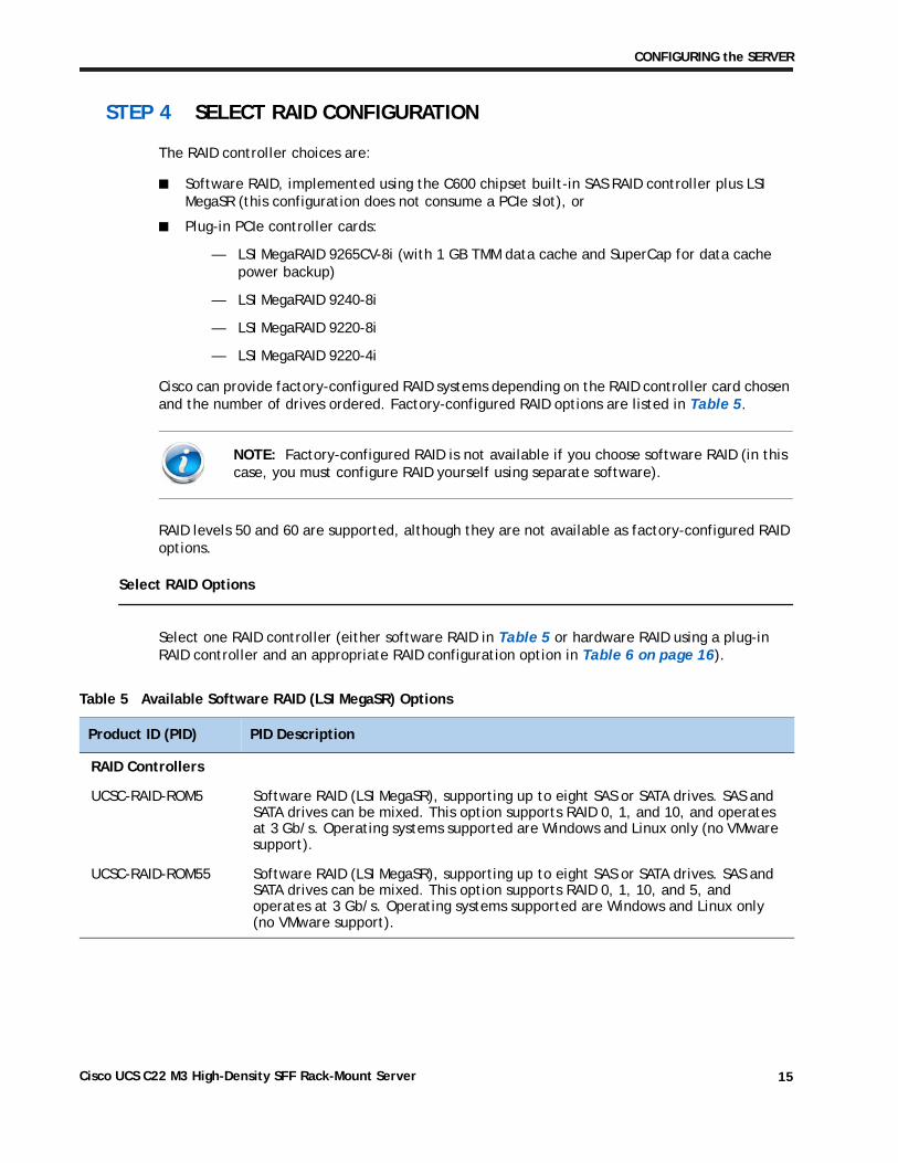
STEP 4 SELECT RAID CONFIGURATION
The RAID controller choices are:
■ Software RAID, implemented using the C600 chipset built-in SAS RAID controller plus LSI MegaSR (this configuration does not consume a PCIe slot), or
■ Plug-in PCIe controller cards:
— LSI MegaRAID 9265CV-8i (with 1 GB TMM data cache and SuperCap for data cache power backup)
— LSI MegaRAID 9240-8i
— LSI MegaRAID 9220-8i
— LSI MegaRAID 9220-4i
Cisco can provide factory-configured RAID systems depending on the RAID controller card chosen and the number of drives ordered. Factory-configured RAID options are listed in Table 5.
RAID levels 50 and 60 are supported, although they are not available as factory-configured RAID options.
Select RAID Options
Select one RAID controller (either software RAID in Table 5 or hardware RAID using a plug-in RAID controller and an appropriate RAID configuration option in Table 6 on page 16).
NOTE: Factory-configured RAID is not available if you choose software RAID (in this case, you must configure RAID yourself using separate software).
Table 5 Available Software RAID (LSI MegaSR) Options
Product ID (PID) PID Description
RAID Controllers
UCSC-RAID-ROM5 Software RAID (LSI MegaSR), supporting up to eight SAS or SATA drives. SAS and SATA drives can be mixed. This option supports RAID 0, 1, and 10, and operates at 3 Gb/s. Operating systems supported are Windows and Linux only (no VMware support).
UCSC-RAID-ROM55 Software RAID (LSI MegaSR), supporting up to eight SAS or SATA drives. SAS and SATA drives can be mixed. This option supports RAID 0, 1, 10, and 5, and operates at 3 Gb/s. Operating systems supported are Windows and Linux only (no VMware support).
Cisco UCS C22 M3 High-Density SFF Rack-Mount Server 15
CONFIGURING the SERVER
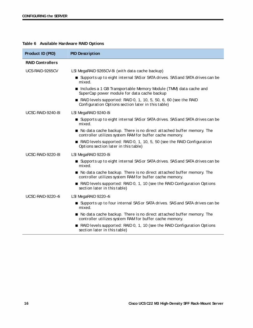
Table 6 Available Hardware RAID Options
Product ID (PID) PID Description
RAID Controllers
UCS-RAID-9265CV LSI MegaRAID 9265CV-8i (with data cache backup)
■ Supports up to eight internal SAS or SATA drives. SAS and SATA drives can be mixed.
■ Includes a 1 GB Transportable Memory Module (TMM) data cache and SuperCap power module for data cache backup
■ RAID levels supported: RAID 0, 1, 10, 5, 50, 6, 60 (see the RAID Configuration Options section later in this table)
UCSC-RAID-9240-8I LSI MegaRAID 9240-8i
■ Supports up to eight internal SAS or SATA drives. SAS and SATA drives can be mixed.
■ No data cache backup. There is no direct attached buffer memory. The controller utilizes system RAM for buffer cache memory.
■ RAID levels supported: RAID 0, 1, 10, 5, 50 (see the RAID Configuration Options section later in this table)
UCSC-RAID-9220-8I LSI MegaRAID 9220-8i
■ Supports up to eight internal SAS or SATA drives. SAS and SATA drives can be mixed.
■ No data cache backup. There is no direct attached buffer memory. The controller utilizes system RAM for buffer cache memory.
■ RAID levels supported: RAID 0, 1, 10 (see the RAID Configuration Options section later in this table)
UCSC-RAID-9220-4i LSI MegaRAID 9220-4i
■ Supports up to four internal SAS or SATA drives. SAS and SATA drives can be mixed.
■ No data cache backup. There is no direct attached buffer memory. The controller utilizes system RAM for buffer cache memory.
■ RAID levels supported: RAID 0, 1, 10 (see the RAID Configuration Options section later in this table)
Cisco UCS C22 M3 High-Density SFF Rack-Mount Server16
CONFIGURING the SERVER
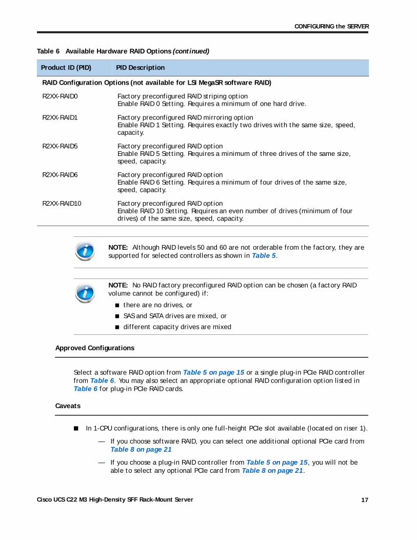
Approved Configurations
Select a software RAID option from Table 5 on page 15 or a single plug-in PCIe RAID controller from Table 6. You may also select an appropriate optional RAID configuration option listed in Table 6 for plug-in PCIe RAID cards.
Caveats
■ In 1-CPU configurations, there is only one full-height PCIe slot available (located on riser 1).
— If you choose software RAID, you can select one additional optional PCIe card from Table 8 on page 21
— If you choose a plug-in RAID controller from Table 5 on page 15, you will not be able to select any optional PCIe card from Table 8 on page 21.
RAID Configuration Options (not available for LSI MegaSR software RAID)
R2XX-RAID0 Factory preconfigured RAID striping option Enable RAID 0 Setting. Requires a minimum of one hard drive.
R2XX-RAID1 Factory preconfigured RAID mirroring option Enable RAID 1 Setting. Requires exactly two drives with the same size, speed, capacity.
R2XX-RAID5 Factory preconfigured RAID option Enable RAID 5 Setting. Requires a minimum of three drives of the same size, speed, capacity.
R2XX-RAID6 Factory preconfigured RAID option Enable RAID 6 Setting. Requires a minimum of four drives of the same size, speed, capacity.
R2XX-RAID10 Factory preconfigured RAID option Enable RAID 10 Setting. Requires an even number of drives (minimum of four drives) of the same size, speed, capacity.
NOTE: Although RAID levels 50 and 60 are not orderable from the factory, they are supported for selected controllers as shown in Table 5.
NOTE: No RAID factory preconfigured RAID option can be chosen (a factory RAID volume cannot be configured) if:
■ there are no drives, or
■ SAS and SATA drives are mixed, or
■ different capacity drives are mixed
Table 6 Available Hardware RAID Options (continued)
Product ID (PID) PID Description
Cisco UCS C22 M3 High-Density SFF Rack-Mount Server 17
CONFIGURING the SERVER
— Note that only a single Cisco 1225 Virtual Interface Card (VIC) card is supported and it must be installed in the full-length, full-height PCIe slot (slot 1) on riser 1, which is the only slot that supports NCSI. So take this into account when populating RAID controller cards.
■ In 2-CPU configurations, there are two PCIe slots available (one full-height slot and one half-height slot).
— If you choose software RAID, you can select up to two additional optional PCIe cards from Table 8 on page 21
— If you choose a plug-in RAID controller from Table 5 on page 15, you will be able to select one additional optional PCIe card from Table 8 on page 21.
■ The optional plug-in PCIe RAID controller cards are all half-height. If you choose one of these cards in a 2-CPU configuration, only the full-height PCIe card slot will be available for an additional optional PCIe card.
■ Note that only a single Cisco 1225 Virtual Interface Card (VIC) card is supported and it must be installed in the full-length, full-height PCIe slot (slot 1) on riser 1, which is the only slot that supports NCSI. So take this into account when populating RAID controller cards.
■ You can choose only one type of RAID controller, either software RAID or a PCIe plug-in controller. If you choose software RAID, both PCIe slots are available for adding optional PCIe cards.
■ For plug-in RAID controller cards, you can choose an optional RAID configuration (RAID 0, 1, 5, 6, or 10), which is preconfigured at the factory. The RAID level you choose must be an available RAID choice for the controller selected. RAID levels 50 and 60 are supported, depending on the RAID controller selected, although they are not available as configuration options.
■ No RAID factory preconfigured RAID option can be chosen (a factory-configured RAID volume is not available) if:
— there are no drives, or
— SAS and SATA drives are mixed, or
— different capacity drives are mixed
Cisco UCS C22 M3 High-Density SFF Rack-Mount Server18
CONFIGURING the SERVER
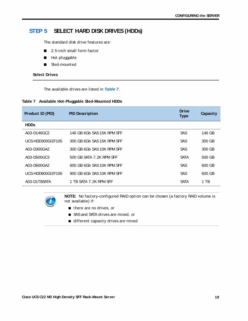
STEP 5 SELECT HARD DISK DRIVES (HDDs)
The standard disk drive features are:
■ 2.5-inch small form factor
■ Hot-pluggable
■ Sled-mounted
Select Drives
The available drives are listed in Table 7.
Table 7 Available Hot-Pluggable Sled-Mounted HDDs
Product ID (PID) PID DescriptionDrive Type
Capacity
HDDs
A03-D146GC2 146 GB 6Gb SAS 15K RPM SFF SAS 146 GB
UCS-HDD300GI2F105 300 GB 6Gb SAS 15K RPM SFF SAS 300 GB
A03-D300GA2 300 GB 6Gb SAS 10K RPM SFF SAS 300 GB
A03-D500GC3 500 GB SATA 7.2K RPM SFF SATA 500 GB
A03-D600GA2 600 GB 6Gb SAS 10K RPM SFF SAS 600 GB
UCS-HDD900GI2F106 900 GB 6Gb SAS 10K RPM SFF SAS 600 GB
A03-D1TBSATA 1 TB SATA 7.2K RPM SFF SATA 1 TB
NOTE: No factory-configured RAID option can be chosen (a factory RAID volume is not available) if:
■ there are no drives, or
■ SAS and SATA drives are mixed, or
■ different capacity drives are mixed
Cisco UCS C22 M3 High-Density SFF Rack-Mount Server 19
CONFIGURING the SERVER
Approved Configurations
(1) Software RAID (LSI MegaSR)
■ Select up to eight SAS/SATA drives (note that no factory-configured RAID option can be chosen for software RAID). You can mix SAS and SATA drives.
(2) LSI MegaRAID 9265CV-8i (with data cache and SuperCap), LSI MegaRAID 9240-8i, and LSI MegaRAID 9220-8i
■ Select up to eight SAS/SATA drives listed in Table 7. You can mix SAS and SATA drives.
(3) LSI MegaRAID 9220-4i
■ Select up to four SAS/SATA drives listed in Table 7. You can mix SAS and SATA drives.
Caveats
■ No factory-configured RAID option can be chosen (a factory RAID volume is not available) if:
— there are no drives, or
— SAS and SATA drives are mixed, or
— different capacity drives are mixed
■ If you select one or more HDDs, you must select either a PCIe RAID controller from Table 6 on page 16 or a software RAID option from Table 5 on page 15.
Cisco UCS C22 M3 High-Density SFF Rack-Mount Server20
CONFIGURING the SERVER
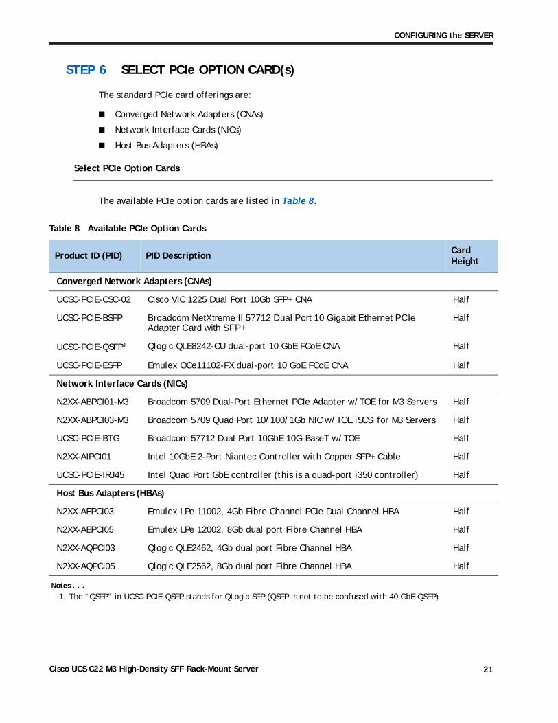
STEP 6 SELECT PCIe OPTION CARD(s)
The standard PCIe card offerings are:
■ Converged Network Adapters (CNAs)
■ Network Interface Cards (NICs)
■ Host Bus Adapters (HBAs)
Select PCIe Option Cards
The available PCIe option cards are listed in Table 8.
Table 8 Available PCIe Option Cards
Product ID (PID) PID DescriptionCard Height
Converged Network Adapters (CNAs)
UCSC-PCIE-CSC-02 Cisco VIC 1225 Dual Port 10Gb SFP+ CNA Half
UCSC-PCIE-BSFP Broadcom NetXtreme II 57712 Dual Port 10 Gigabit Ethernet PCIe Adapter Card with SFP+
Half
UCSC-PCIE-QSFP1
Notes . . .
1. The “QSFP” in UCSC-PCIE-QSFP stands for QLogic SFP (QSFP is not to be confused with 40 GbE QSFP)
Qlogic QLE8242-CU dual-port 10 GbE FCoE CNA Half
UCSC-PCIE-ESFP Emulex OCe11102-FX dual-port 10 GbE FCoE CNA Half
Network Interface Cards (NICs)
N2XX-ABPCI01-M3 Broadcom 5709 Dual-Port Ethernet PCIe Adapter w/TOE for M3 Servers Half
N2XX-ABPCI03-M3 Broadcom 5709 Quad Port 10/100/1Gb NIC w/TOE iSCSI for M3 Servers Half
UCSC-PCIE-BTG Broadcom 57712 Dual Port 10GbE 10G-BaseT w/TOE Half
N2XX-AIPCI01 Intel 10GbE 2-Port Niantec Controller with Copper SFP+ Cable Half
UCSC-PCIE-IRJ45 Intel Quad Port GbE controller (this is a quad-port i350 controller) Half
Host Bus Adapters (HBAs)
N2XX-AEPCI03 Emulex LPe 11002, 4Gb Fibre Channel PCIe Dual Channel HBA Half
N2XX-AEPCI05 Emulex LPe 12002, 8Gb dual port Fibre Channel HBA Half
N2XX-AQPCI03 Qlogic QLE2462, 4Gb dual port Fibre Channel HBA Half
N2XX-AQPCI05 Qlogic QLE2562, 8Gb dual port Fibre Channel HBA Half
Cisco UCS C22 M3 High-Density SFF Rack-Mount Server 21
CONFIGURING the SERVER
Approved Configurations
(1) No RAID controller plug-in card
■ If you did not choose a plug-in RAID controller card (for example, you selected software RAID (LSI MegaSR) or no RAID controller at all), you can select up to one PCIe option card listed in Table 8 on page 21 for 1-CPU configurations or up to two cards for 2-CPU configurations.
(2) One RAID controller plug-in card
■ If you selected a plug-in PCIe RAID controller, you cannot select any additional PCIe cards for 1-CPU configurations; however, you can select one additional optional PCIe cards for 2-CPU configurations.
Caveats
■ Only a single Cisco 1225 Virtual Interface Card (VIC) card is supported and it must be installed in the full-height slot of riser 1, which is the only slot that supports NCSI.
■ All PCIe cards will fit in either riser 1 or riser 2, except the VIC card, which must be installed in the full-height slot of riser 1. The Cisco 1225 VIC card must be plugged into slot 1, which supports NCSI.
■ Additional considerations for the Cisco 1225 VIC card:
— Supports 10G SFP+ optical and copper twinax connections
— Supported only in PCIe slot 1 of this server. Slot 1 can operate while the server is in standby power mode.
— Requires that the server has CIMC firmware version 1.4(6) or later installed. There is a heartbeat LED on the top of the card that indicates when firmware is active.
— To use this card for UCS integration (Cisco UCS Manager mode) with Cisco UCS Manager 2.1(0) or later, the minimum card-firmware and uboot image level is 2.1(0.306).
■ To help ensure that your operating system is compatible with the card you have selected, check the Hardware Compatibility List at this URL:
http://www.cisco.com/en/US/products/ps10477/prod_technical_reference_list.html
NOTE: If a plug-in RAID controller card is installed, any optional PCIe card you select will be installed in the full-height slot. RAID controllers are always installed in the half-height slot.
Cisco UCS C22 M3 High-Density SFF Rack-Mount Server22
CONFIGURING the SERVER
STEP 7 ORDER OPTIONAL NETWORK CARD ACCESSORIES
Copper twinax cables and SFP optical modules may be ordered to support the two-port network cards that are available with the server.
Choose Optional Twinax Cables
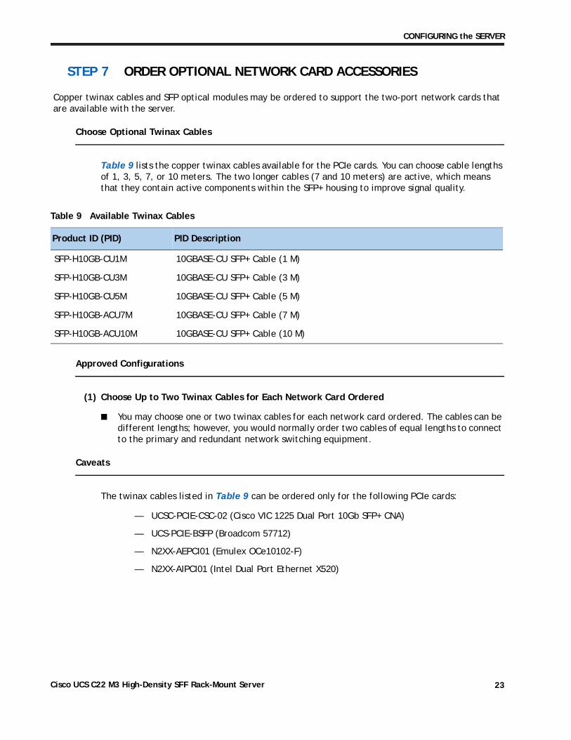
Table 9 lists the copper twinax cables available for the PCIe cards. You can choose cable lengths of 1, 3, 5, 7, or 10 meters. The two longer cables (7 and 10 meters) are active, which means that they contain active components within the SFP+ housing to improve signal quality.
Approved Configurations
(1) Choose Up to Two Twinax Cables for Each Network Card Ordered
■ You may choose one or two twinax cables for each network card ordered. The cables can be different lengths; however, you would normally order two cables of equal lengths to connect to the primary and redundant network switching equipment.
Caveats
The twinax cables listed in Table 9 can be ordered only for the following PCIe cards:
— UCSC-PCIE-CSC-02 (Cisco VIC 1225 Dual Port 10Gb SFP+ CNA)
— UCS-PCIE-BSFP (Broadcom 57712)
— N2XX-AEPCI01 (Emulex OCe10102-F)
— N2XX-AIPCI01 (Intel Dual Port Ethernet X520)
Table 9 Available Twinax Cables
Product ID (PID) PID Description
SFP-H10GB-CU1M 10GBASE-CU SFP+ Cable (1 M)
SFP-H10GB-CU3M 10GBASE-CU SFP+ Cable (3 M)
SFP-H10GB-CU5M 10GBASE-CU SFP+ Cable (5 M)
SFP-H10GB-ACU7M 10GBASE-CU SFP+ Cable (7 M)
SFP-H10GB-ACU10M 10GBASE-CU SFP+ Cable (10 M)
Cisco UCS C22 M3 High-Density SFF Rack-Mount Server 23
CONFIGURING the SERVER
Choose Optional SFP Modules
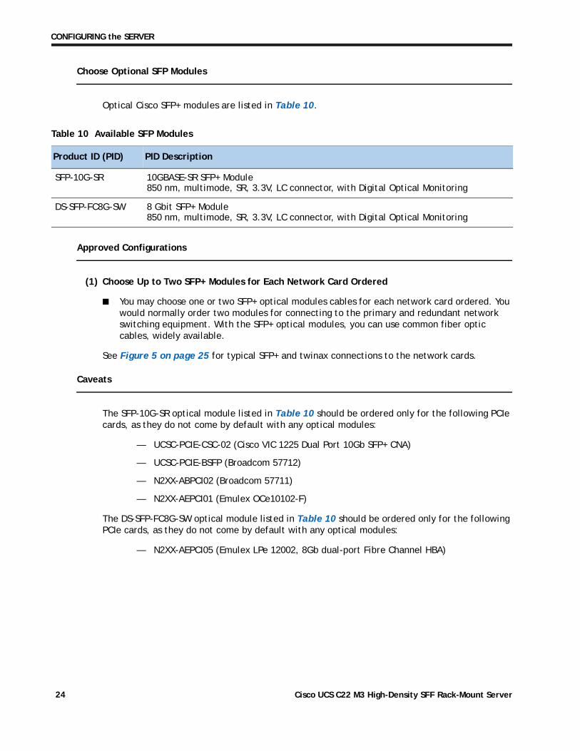
Optical Cisco SFP+ modules are listed in Table 10.
Approved Configurations
(1) Choose Up to Two SFP+ Modules for Each Network Card Ordered
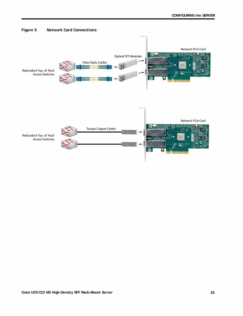
■ You may choose one or two SFP+ optical modules cables for each network card ordered. You would normally order two modules for connecting to the primary and redundant network switching equipment. With the SFP+ optical modules, you can use common fiber optic cables, widely available.
See Figure 5 on page 25 for typical SFP+ and twinax connections to the network cards.
Caveats
The SFP-10G-SR optical module listed in Table 10 should be ordered only for the following PCIe cards, as they do not come by default with any optical modules:
— UCSC-PCIE-CSC-02 (Cisco VIC 1225 Dual Port 10Gb SFP+ CNA)
— UCSC-PCIE-BSFP (Broadcom 57712)
— N2XX-ABPCI02 (Broadcom 57711)
— N2XX-AEPCI01 (Emulex OCe10102-F)
The DS-SFP-FC8G-SW optical module listed in Table 10 should be ordered only for the following PCIe cards, as they do not come by default with any optical modules:
— N2XX-AEPCI05 (Emulex LPe 12002, 8Gb dual-port Fibre Channel HBA)
Table 10 Available SFP Modules
Product ID (PID) PID Description
SFP-10G-SR 10GBASE-SR SFP+ Module 850 nm, multimode, SR, 3.3V, LC connector, with Digital Optical Monitoring
DS-SFP-FC8G-SW 8 Gbit SFP+ Module 850 nm, multimode, SR, 3.3V, LC connector, with Digital Optical Monitoring
Cisco UCS C22 M3 High-Density SFF Rack-Mount Server24
CONFIGURING the SERVER
Figure 5 Network Card Connections
Cisco UCS C22 M3 High-Density SFF Rack-Mount Server 25
CONFIGURING the SERVER
STEP 8 SELECT AC POWER CORD(s)
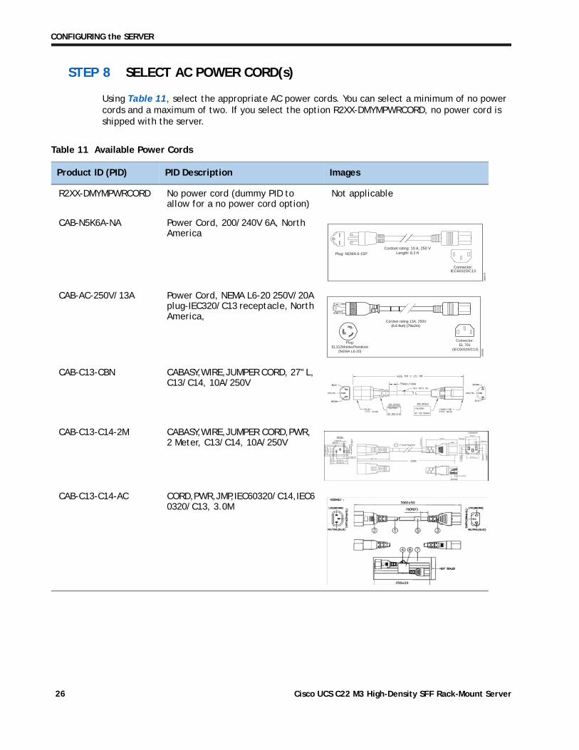
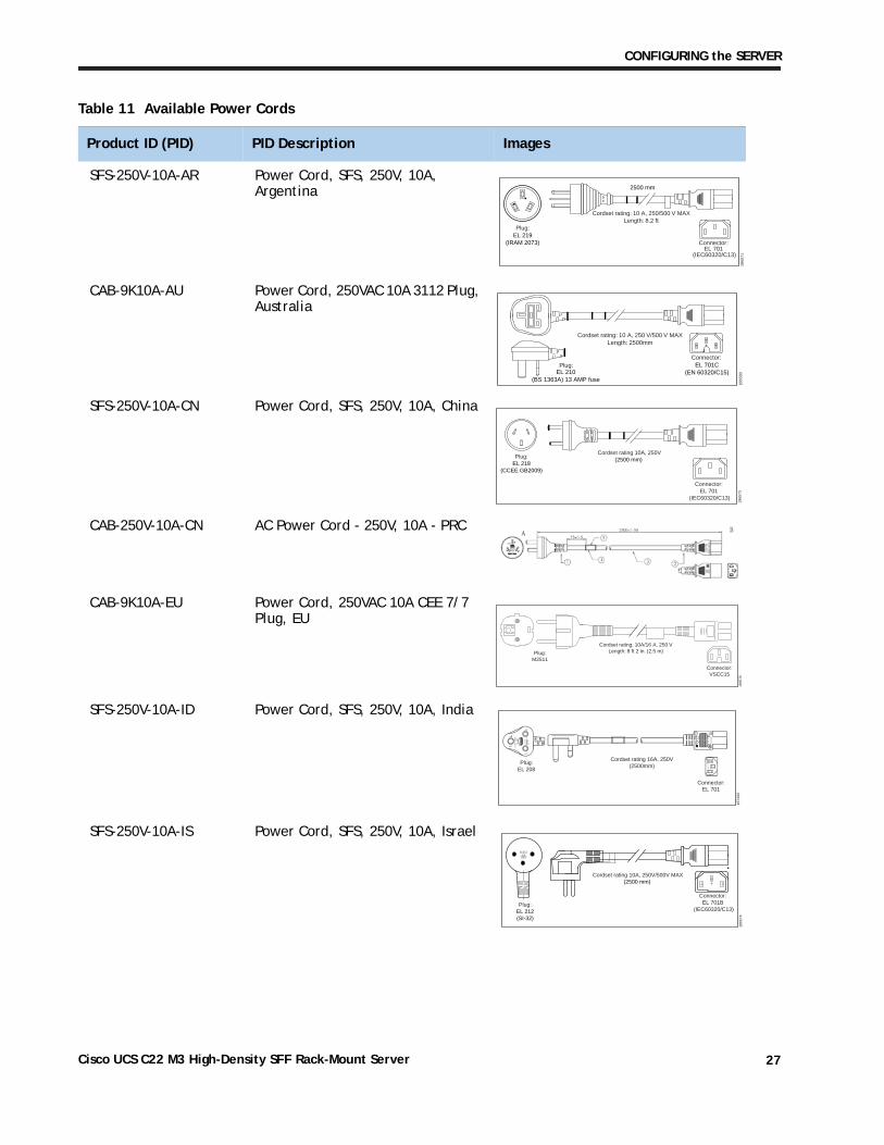
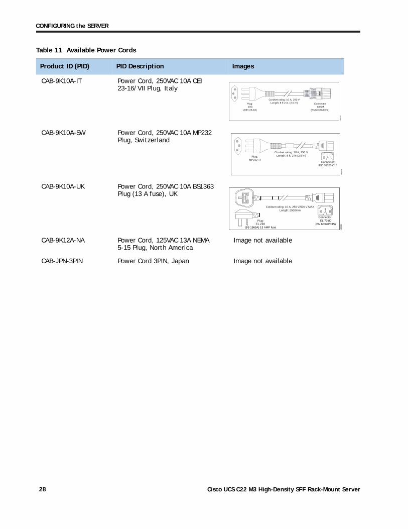
Using Table 11, select the appropriate AC power cords. You can select a minimum of no power cords and a maximum of two. If you select the option R2XX-DMYMPWRCORD, no power cord is shipped with the server.
Table 11 Available Power Cords
Product ID (PID) PID Description Images
R2XX-DMYMPWRCORD No power cord (dummy PID to allow for a no power cord option)
Not applicable
CAB-N5K6A-NA Power Cord, 200/240V 6A, North America
CAB-AC-250V/13A Power Cord, NEMA L6-20 250V/20A plug-IEC320/C13 receptacle, North America,
CAB-C13-CBN CABASY,WIRE,JUMPER CORD, 27" L, C13/C14, 10A/250V
CAB-C13-C14-2M CABASY,WIRE,JUMPER CORD,PWR, 2 Meter, C13/C14, 10A/250V
CAB-C13-C14-AC CORD,PWR,JMP,IEC60320/C14,IEC60320/C13, 3.0M
Cordset rating: 10 A, 250 VLength: 8.2 ft
1865
70
Plug: NEMA 6-15P
Connector:IEC60320/C13
Cordset rating 13A, 250V(6.6 feet) (79±2m)
Plug:EL312MoldedTwistlock
(NEMA L6-20)
1865
68
Connector:EL 701
(IEC60320/C13)
Cisco UCS C22 M3 High-Density SFF Rack-Mount Server26
CONFIGURING the SERVER
SFS-250V-10A-AR Power Cord, SFS, 250V, 10A, Argentina
CAB-9K10A-AU Power Cord, 250VAC 10A 3112 Plug, Australia
SFS-250V-10A-CN Power Cord, SFS, 250V, 10A, China
CAB-250V-10A-CN AC Power Cord - 250V, 10A - PRC
CAB-9K10A-EU Power Cord, 250VAC 10A CEE 7/7 Plug, EU
SFS-250V-10A-ID Power Cord, SFS, 250V, 10A, India
SFS-250V-10A-IS Power Cord, SFS, 250V, 10A, Israel
Table 11 Available Power Cords
Product ID (PID) PID Description Images
1865
71
2500 mm
Cordset rating: 10 A, 250/500 V MAXLength: 8.2 ft
Plug:EL 219
(IRAM 2073) Connector:EL 701
(IEC60320/C13)
Plug:
Cordset rating: 10 A, 250 V/500 V MAXLength: 2500mm
1865
80
Connector:EL 701C
(EN 60320/C15)EL 210(BS 1363A) 13 AMP fuse
Cordset rating 10A, 250V(2500 mm)
Plug:EL 218
(CCEE GB2009)
1865
73
Connector:EL 701
(IEC60320/C13)
Connector:VSCC15
Cordset rating: 10A/16 A, 250 VLength: 8 ft 2 in. (2.5 m)Plug:
M2511
1865
76
OVE
Cordset rating 16A, 250V(2500mm)
Plug:EL 208
1874
90
Connector:EL 701
Cordset rating 10A, 250V/500V MAX(2500 mm)
Plug:EL 212(SI-32)
1865
74
Connector:EL 701B
(IEC60320/C13)
EL-21216A250V
Cisco UCS C22 M3 High-Density SFF Rack-Mount Server 27
CONFIGURING the SERVER
CAB-9K10A-IT Power Cord, 250VAC 10A CEI 23-16/VII Plug, Italy
CAB-9K10A-SW Power Cord, 250VAC 10A MP232 Plug, Switzerland
CAB-9K10A-UK Power Cord, 250VAC 10A BS1363 Plug (13 A fuse), UK
CAB-9K12A-NA Power Cord, 125VAC 13A NEMA 5-15 Plug, North America
Image not available
CAB-JPN-3PIN Power Cord 3PIN, Japan Image not available
Table 11 Available Power Cords
Product ID (PID) PID Description Images
Plug: I/3G
(CEI 23-16)
Connector C15M
(EN60320/C15 )
Cordset rating: 10 A, 250 VLength: 8 ft 2 in. (2.5 m)
1865
75
Plug:MP232-R
Cordset rating: 10 A, 250 VLength: 8 ft. 2 in (2.5 m)
1865
78
Connector:IEC 60320 C15
Plug:
Cordset rating: 10 A, 250 V/500 V MAXLength: 2500mm
1865
80
Connector:EL 701C
(EN 60320/C15)EL 210(BS 1363A) 13 AMP fuse
Cisco UCS C22 M3 High-Density SFF Rack-Mount Server28
CONFIGURING the SERVER
STEP 9 ORDER POWER SUPPLY
The C22 M3 server accommodates one power supply. A lightly loaded server can operate from one 450 W power supply. A fully loaded server might need to be powered with a 650 W power supply (see Table 12).
Prior to making a power supply selection, the UCS Power Calculator should be run to determine the right size power supply for your server configuration. A fully configured C22 M3 server may require the 650 W power supply. The UCS Power Calculator can be found at the following link:
https://express.salire.com/Go/Cisco/Cisco-UCS-Power-Calculator.aspx
Table 12 Power Supply PIDs
Product ID (PID) PID Description
UCSC-PSU-450W 450 W power supply
UCSC-PSU-650W 650 W power supply
Cisco UCS C22 M3 High-Density SFF Rack-Mount Server 29
CONFIGURING the SERVER
STEP 10 ORDER OPTIONAL REVERSIBLE CABLE MANAGEMENT ARM
The reversible cable management arm mounts on either the right or left slide rails at the rear of the server and is used for cable management. Use Table 13 to order a cable management arm.
For more information about the cable management arm, see the Cisco UCS C22 M3 Installation and Service Guide at this URL:
http://www.cisco.com/en/US/docs/unified_computing/ucs/c/hw/C22/install/C22.pdf
Table 13 Cable Management Arm
Product ID (PID) PID Description
UCSC-CMA1 Cable Management Arm for C22 rack servers
NOTE: If you order and install a cable management arm, you will need the longest power cable available.
Cisco UCS C22 M3 High-Density SFF Rack-Mount Server30
CONFIGURING the SERVER
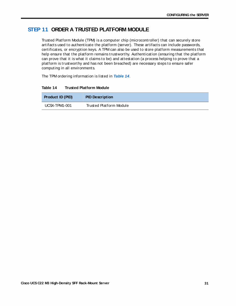
STEP 11 ORDER A TRUSTED PLATFORM MODULE
Trusted Platform Module (TPM) is a computer chip (microcontroller) that can securely store artifacts used to authenticate the platform (server). These artifacts can include passwords, certificates, or encryption keys. A TPM can also be used to store platform measurements that help ensure that the platform remains trustworthy. Authentication (ensuring that the platform can prove that it is what it claims to be) and attestation (a process helping to prove that a platform is trustworthy and has not been breached) are necessary steps to ensure safer computing in all environments.
The TPM ordering information is listed in Table 14.
Table 14 Trusted Platform Module
Product ID (PID) PID Description
UCSX-TPM1-001 Trusted Platform Module
Cisco UCS C22 M3 High-Density SFF Rack-Mount Server 31
CONFIGURING the SERVER
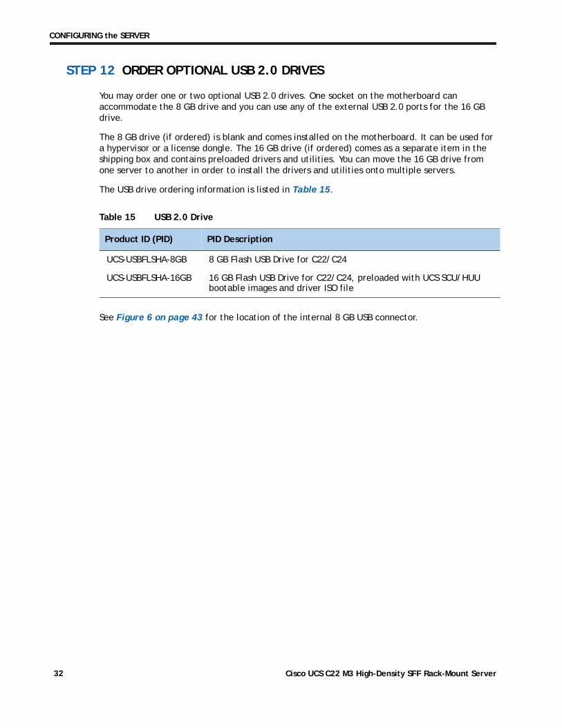
STEP 12 ORDER OPTIONAL USB 2.0 DRIVES
You may order one or two optional USB 2.0 drives. One socket on the motherboard can accommodate the 8 GB drive and you can use any of the external USB 2.0 ports for the 16 GB drive.
The 8 GB drive (if ordered) is blank and comes installed on the motherboard. It can be used for a hypervisor or a license dongle. The 16 GB drive (if ordered) comes as a separate item in the shipping box and contains preloaded drivers and utilities. You can move the 16 GB drive from one server to another in order to install the drivers and utilities onto multiple servers.
The USB drive ordering information is listed in Table 15.
See Figure 6 on page 43 for the location of the internal 8 GB USB connector.
Table 15 USB 2.0 Drive
Product ID (PID) PID Description
UCS-USBFLSHA-8GB 8 GB Flash USB Drive for C22/C24
UCS-USBFLSHA-16GB 16 GB Flash USB Drive for C22/C24, preloaded with UCS SCU/HUU bootable images and driver ISO file
Cisco UCS C22 M3 High-Density SFF Rack-Mount Server32
CONFIGURING the SERVER
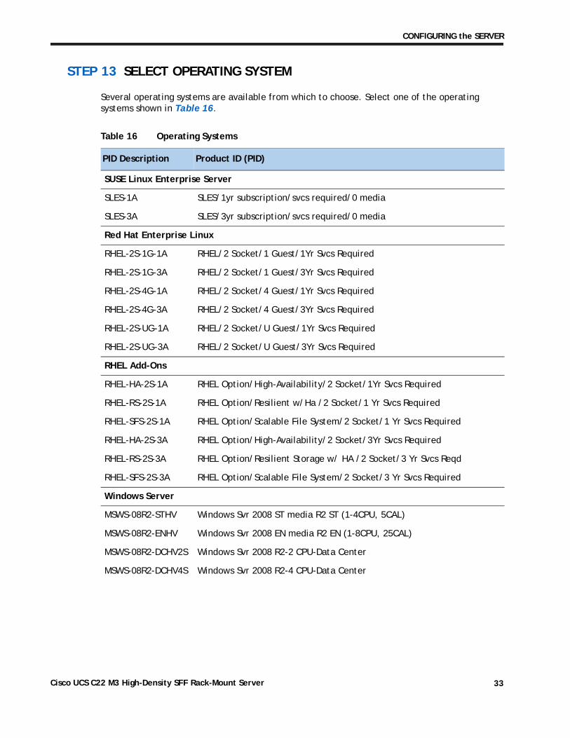
STEP 13 SELECT OPERATING SYSTEM
Several operating systems are available from which to choose. Select one of the operating systems shown in Table 16.
Table 16 Operating Systems
PID Description Product ID (PID)
SUSE Linux Enterprise Server
SLES-1A SLES/1yr subscription/svcs required/0 media
SLES-3A SLES/3yr subscription/svcs required/0 media
Red Hat Enterprise Linux
RHEL-2S-1G-1A RHEL/2 Socket/1 Guest/1Yr Svcs Required
RHEL-2S-1G-3A RHEL/2 Socket/1 Guest/3Yr Svcs Required
RHEL-2S-4G-1A RHEL/2 Socket/4 Guest/1Yr Svcs Required
RHEL-2S-4G-3A RHEL/2 Socket/4 Guest/3Yr Svcs Required
RHEL-2S-UG-1A RHEL/2 Socket/U Guest/1Yr Svcs Required
RHEL-2S-UG-3A RHEL/2 Socket/U Guest/3Yr Svcs Required
RHEL Add-Ons
RHEL-HA-2S-1A RHEL Option/High-Availability/2 Socket/1Yr Svcs Required
RHEL-RS-2S-1A RHEL Option/Resilient w/Ha /2 Socket/1 Yr Svcs Required
RHEL-SFS-2S-1A RHEL Option/Scalable File System/2 Socket/1 Yr Svcs Required
RHEL-HA-2S-3A RHEL Option/High-Availability/2 Socket/3Yr Svcs Required
RHEL-RS-2S-3A RHEL Option/Resilient Storage w/ HA /2 Socket/3 Yr Svcs Reqd
RHEL-SFS-2S-3A RHEL Option/Scalable File System/2 Socket/3 Yr Svcs Required
Windows Server
MSWS-08R2-STHV Windows Svr 2008 ST media R2 ST (1-4CPU, 5CAL)
MSWS-08R2-ENHV Windows Svr 2008 EN media R2 EN (1-8CPU, 25CAL)
MSWS-08R2-DCHV2S Windows Svr 2008 R2-2 CPU-Data Center
MSWS-08R2-DCHV4S Windows Svr 2008 R2-4 CPU-Data Center
Cisco UCS C22 M3 High-Density SFF Rack-Mount Server 33
CONFIGURING the SERVER
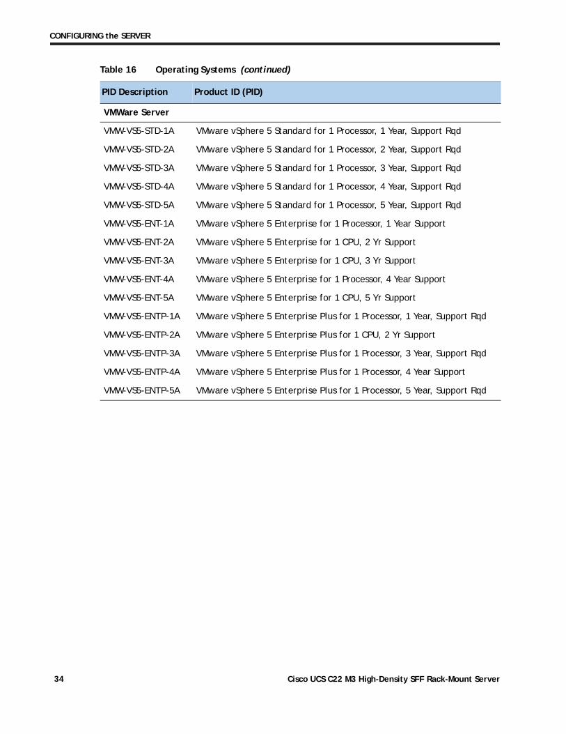
VMWare Server
VMW-VS5-STD-1A VMware vSphere 5 Standard for 1 Processor, 1 Year, Support Rqd
VMW-VS5-STD-2A VMware vSphere 5 Standard for 1 Processor, 2 Year, Support Rqd
VMW-VS5-STD-3A VMware vSphere 5 Standard for 1 Processor, 3 Year, Support Rqd
VMW-VS5-STD-4A VMware vSphere 5 Standard for 1 Processor, 4 Year, Support Rqd
VMW-VS5-STD-5A VMware vSphere 5 Standard for 1 Processor, 5 Year, Support Rqd
VMW-VS5-ENT-1A VMware vSphere 5 Enterprise for 1 Processor, 1 Year Support
VMW-VS5-ENT-2A VMware vSphere 5 Enterprise for 1 CPU, 2 Yr Support
VMW-VS5-ENT-3A VMware vSphere 5 Enterprise for 1 CPU, 3 Yr Support
VMW-VS5-ENT-4A VMware vSphere 5 Enterprise for 1 Processor, 4 Year Support
VMW-VS5-ENT-5A VMware vSphere 5 Enterprise for 1 CPU, 5 Yr Support
VMW-VS5-ENTP-1A VMware vSphere 5 Enterprise Plus for 1 Processor, 1 Year, Support Rqd
VMW-VS5-ENTP-2A VMware vSphere 5 Enterprise Plus for 1 CPU, 2 Yr Support
VMW-VS5-ENTP-3A VMware vSphere 5 Enterprise Plus for 1 Processor, 3 Year, Support Rqd
VMW-VS5-ENTP-4A VMware vSphere 5 Enterprise Plus for 1 Processor, 4 Year Support
VMW-VS5-ENTP-5A VMware vSphere 5 Enterprise Plus for 1 Processor, 5 Year, Support Rqd
Table 16 Operating Systems (continued)
PID Description Product ID (PID)
Cisco UCS C22 M3 High-Density SFF Rack-Mount Server34
CONFIGURING the SERVER
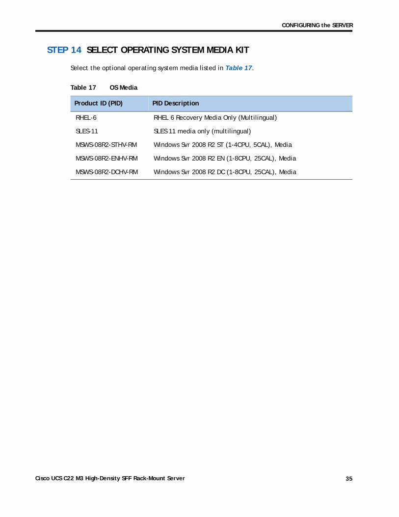
STEP 14 SELECT OPERATING SYSTEM MEDIA KIT
Select the optional operating system media listed in Table 17.
Table 17 OS Media
Product ID (PID) PID Description
RHEL-6 RHEL 6 Recovery Media Only (Multilingual)
SLES-11 SLES 11 media only (multilingual)
MSWS-08R2-STHV-RM Windows Svr 2008 R2 ST (1-4CPU, 5CAL), Media
MSWS-08R2-ENHV-RM Windows Svr 2008 R2 EN (1-8CPU, 25CAL), Media
MSWS-08R2-DCHV-RM Windows Svr 2008 R2 DC (1-8CPU, 25CAL), Media
Cisco UCS C22 M3 High-Density SFF Rack-Mount Server 35
CONFIGURING the SERVER
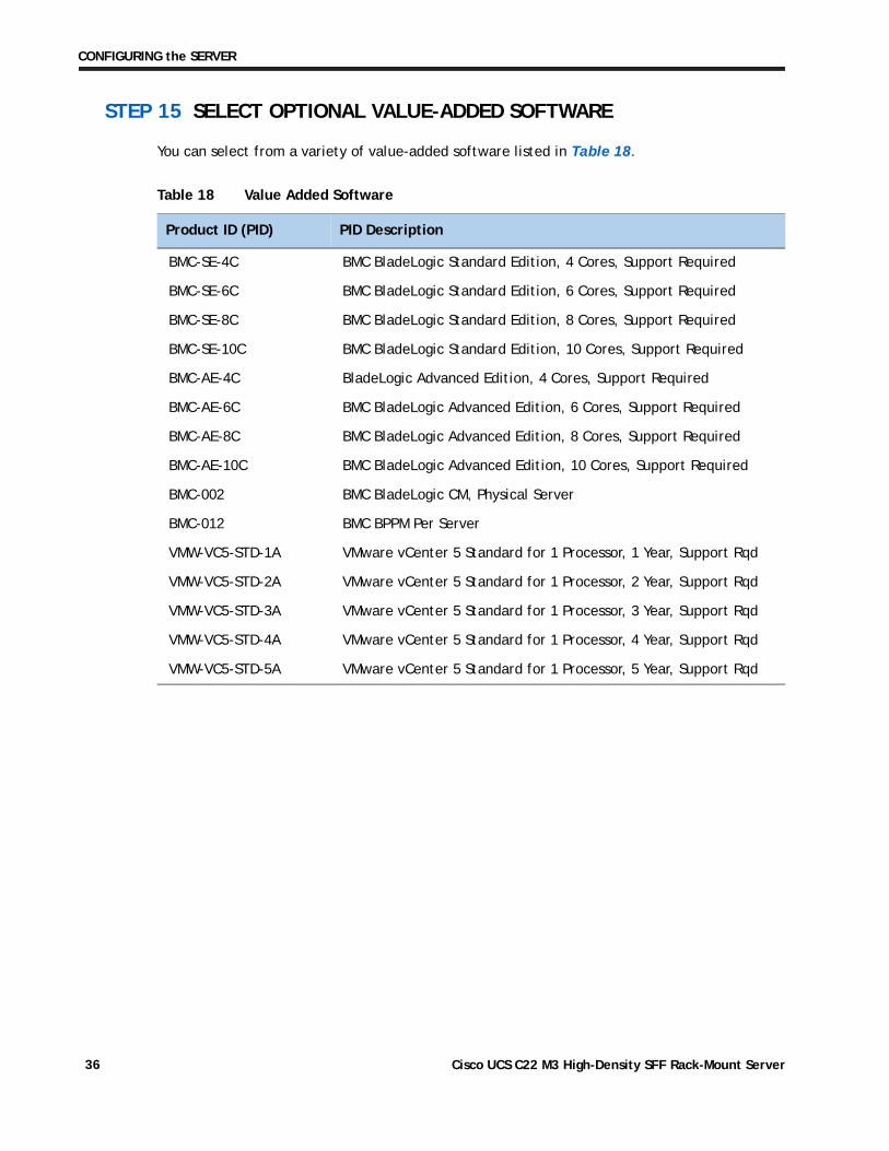
STEP 15 SELECT OPTIONAL VALUE-ADDED SOFTWARE
You can select from a variety of value-added software listed in Table 18.
Table 18 Value Added Software
Product ID (PID) PID Description
BMC-SE-4C BMC BladeLogic Standard Edition, 4 Cores, Support Required
BMC-SE-6C BMC BladeLogic Standard Edition, 6 Cores, Support Required
BMC-SE-8C BMC BladeLogic Standard Edition, 8 Cores, Support Required
BMC-SE-10C BMC BladeLogic Standard Edition, 10 Cores, Support Required
BMC-AE-4C BladeLogic Advanced Edition, 4 Cores, Support Required
BMC-AE-6C BMC BladeLogic Advanced Edition, 6 Cores, Support Required
BMC-AE-8C BMC BladeLogic Advanced Edition, 8 Cores, Support Required
BMC-AE-10C BMC BladeLogic Advanced Edition, 10 Cores, Support Required
BMC-002 BMC BladeLogic CM, Physical Server
BMC-012 BMC BPPM Per Server
VMW-VC5-STD-1A VMware vCenter 5 Standard for 1 Processor, 1 Year, Support Rqd
VMW-VC5-STD-2A VMware vCenter 5 Standard for 1 Processor, 2 Year, Support Rqd
VMW-VC5-STD-3A VMware vCenter 5 Standard for 1 Processor, 3 Year, Support Rqd
VMW-VC5-STD-4A VMware vCenter 5 Standard for 1 Processor, 4 Year, Support Rqd
VMW-VC5-STD-5A VMware vCenter 5 Standard for 1 Processor, 5 Year, Support Rqd
Cisco UCS C22 M3 High-Density SFF Rack-Mount Server36
CONFIGURING the SERVER
STEP 16 SELECT SERVICE and SUPPORT LEVEL
A variety of service options are available, as described in this section.
Unified Computing Warranty, No Contract
If you have noncritical implementations and choose no service contract, the following coverage is supplied:
■ Three-year parts coverage.
■ Next business day (NBD) onsite parts replacement eight hours a day, five days a week.
■ 90-day software warranty on media.
■ Downloads of BIOS, drivers, and firmware updates.
■ UCSM updates for systems with Unified Computing System Manager. These updates include minor enhancements and bug fixes that are designed to maintain the compliance of UCSM with published specifications, release notes, and industry standards.
Please visit Cisco Unified Computing Warranty for more information on the Cisco Unified Computing Warranty.
Unified Computing Warranty Plus Service
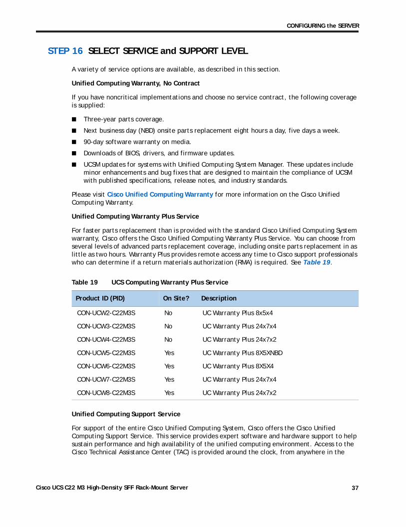
For faster parts replacement than is provided with the standard Cisco Unified Computing System warranty, Cisco offers the Cisco Unified Computing Warranty Plus Service. You can choose from several levels of advanced parts replacement coverage, including onsite parts replacement in as little as two hours. Warranty Plus provides remote access any time to Cisco support professionals who can determine if a return materials authorization (RMA) is required. See Table 19.
Unified Computing Support Service
For support of the entire Cisco Unified Computing System, Cisco offers the Cisco Unified Computing Support Service. This service provides expert software and hardware support to help sustain performance and high availability of the unified computing environment. Access to the Cisco Technical Assistance Center (TAC) is provided around the clock, from anywhere in the
Table 19 UCS Computing Warranty Plus Service
Product ID (PID) On Site? Description
CON-UCW2-C22M3S No UC Warranty Plus 8x5x4
CON-UCW3-C22M3S No UC Warranty Plus 24x7x4
CON-UCW4-C22M3S No UC Warranty Plus 24x7x2
CON-UCW5-C22M3S Yes UC Warranty Plus 8X5XNBD
CON-UCW6-C22M3S Yes UC Warranty Plus 8X5X4
CON-UCW7-C22M3S Yes UC Warranty Plus 24x7x4
CON-UCW8-C22M3S Yes UC Warranty Plus 24x7x2
Cisco UCS C22 M3 High-Density SFF Rack-Mount Server 37
CONFIGURING the SERVER
world. As a part of this service, Cisco will assist in issues involving third-party software that have been certified for use on the Cisco Unified Computing System
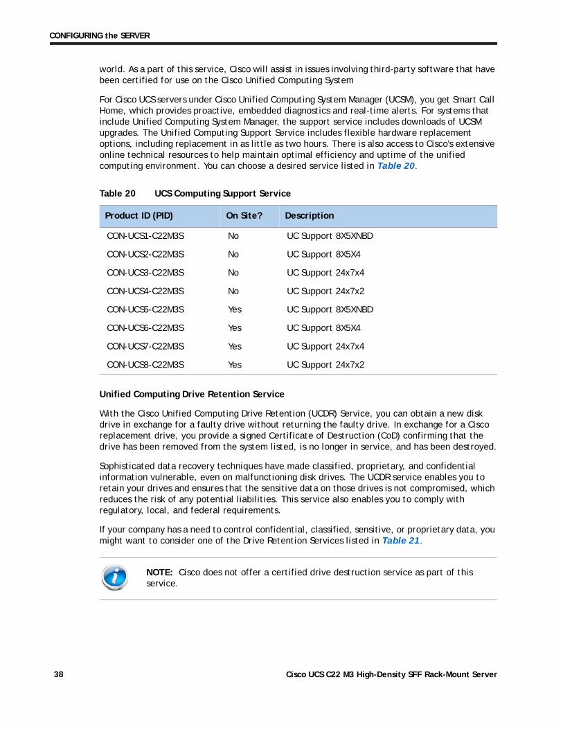
For Cisco UCS servers under Cisco Unified Computing System Manager (UCSM), you get Smart Call Home, which provides proactive, embedded diagnostics and real-time alerts. For systems that include Unified Computing System Manager, the support service includes downloads of UCSM upgrades. The Unified Computing Support Service includes flexible hardware replacement options, including replacement in as little as two hours. There is also access to Cisco's extensive online technical resources to help maintain optimal efficiency and uptime of the unified computing environment. You can choose a desired service listed in Table 20.
Unified Computing Drive Retention Service
With the Cisco Unified Computing Drive Retention (UCDR) Service, you can obtain a new disk drive in exchange for a faulty drive without returning the faulty drive. In exchange for a Cisco replacement drive, you provide a signed Certificate of Destruction (CoD) confirming that the drive has been removed from the system listed, is no longer in service, and has been destroyed.
Sophisticated data recovery techniques have made classified, proprietary, and confidential information vulnerable, even on malfunctioning disk drives. The UCDR service enables you to retain your drives and ensures that the sensitive data on those drives is not compromised, which reduces the risk of any potential liabilities. This service also enables you to comply with regulatory, local, and federal requirements.
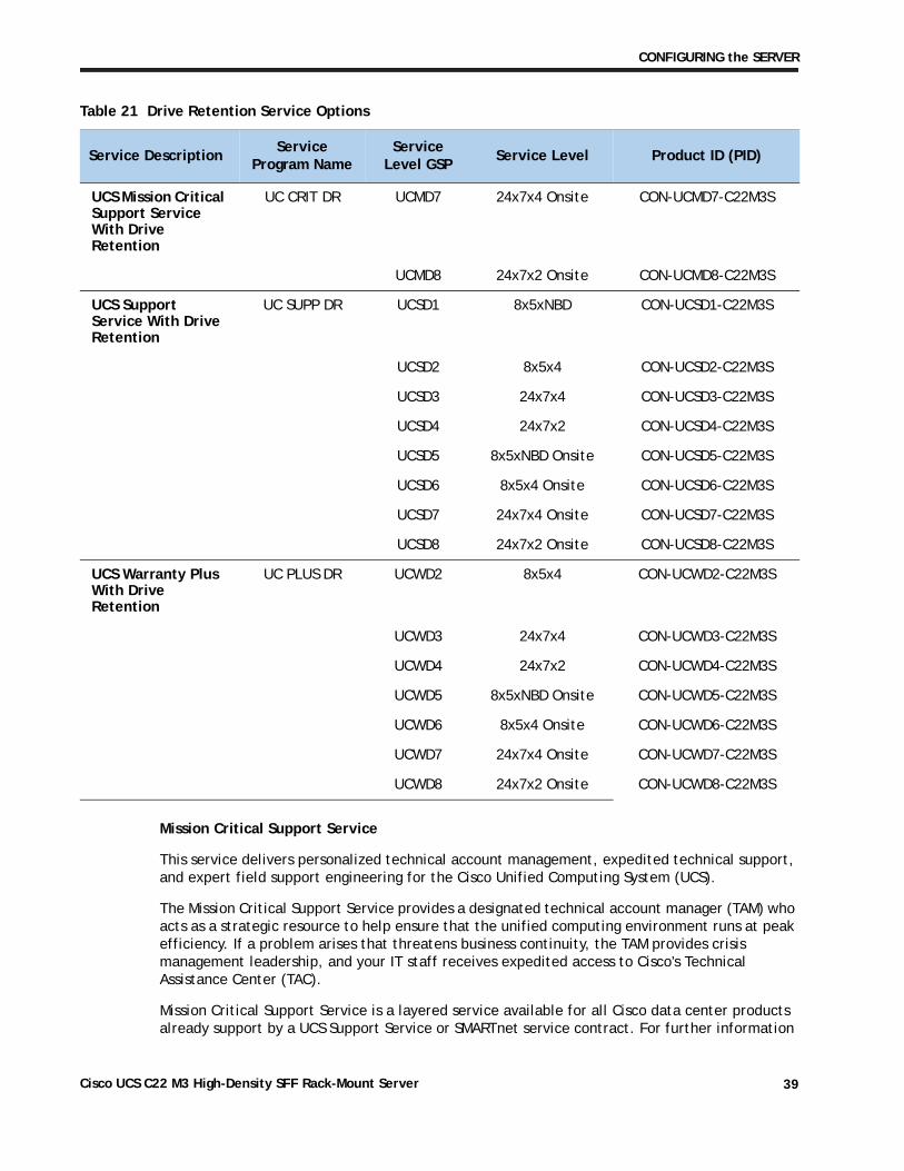
If your company has a need to control confidential, classified, sensitive, or proprietary data, you might want to consider one of the Drive Retention Services listed in Table 21.
Table 20 UCS Computing Support Service
Product ID (PID) On Site? Description
CON-UCS1-C22M3S No UC Support 8X5XNBD
CON-UCS2-C22M3S No UC Support 8X5X4
CON-UCS3-C22M3S No UC Support 24x7x4
CON-UCS4-C22M3S No UC Support 24x7x2
CON-UCS5-C22M3S Yes UC Support 8X5XNBD
CON-UCS6-C22M3S Yes UC Support 8X5X4
CON-UCS7-C22M3S Yes UC Support 24x7x4
CON-UCS8-C22M3S Yes UC Support 24x7x2
NOTE: Cisco does not offer a certified drive destruction service as part of this service.
Cisco UCS C22 M3 High-Density SFF Rack-Mount Server38
CONFIGURING the SERVER
Mission Critical Support Service
This service delivers personalized technical account management, expedited technical support, and expert field support engineering for the Cisco Unified Computing System (UCS).
The Mission Critical Support Service provides a designated technical account manager (TAM) who acts as a strategic resource to help ensure that the unified computing environment runs at peak efficiency. If a problem arises that threatens business continuity, the TAM provides crisis management leadership, and your IT staff receives expedited access to Cisco's Technical Assistance Center (TAC).
Mission Critical Support Service is a layered service available for all Cisco data center products already support by a UCS Support Service or SMARTnet service contract. For further information
Table 21 Drive Retention Service Options
Service DescriptionService
Program NameService
Level GSPService Level Product ID (PID)
UCS Mission Critical Support Service With Drive Retention
UC CRIT DR UCMD7 24x7x4 Onsite CON-UCMD7-C22M3S
UCMD8 24x7x2 Onsite CON-UCMD8-C22M3S
UCS Support Service With Drive Retention
UC SUPP DR UCSD1 8x5xNBD CON-UCSD1-C22M3S
UCSD2 8x5x4 CON-UCSD2-C22M3S
UCSD3 24x7x4 CON-UCSD3-C22M3S
UCSD4 24x7x2 CON-UCSD4-C22M3S
UCSD5 8x5xNBD Onsite CON-UCSD5-C22M3S
UCSD6 8x5x4 Onsite CON-UCSD6-C22M3S
UCSD7 24x7x4 Onsite CON-UCSD7-C22M3S
UCSD8 24x7x2 Onsite CON-UCSD8-C22M3S
UCS Warranty Plus With Drive Retention
UC PLUS DR UCWD2 8x5x4 CON-UCWD2-C22M3S
UCWD3 24x7x4 CON-UCWD3-C22M3S
UCWD4 24x7x2 CON-UCWD4-C22M3S
UCWD5 8x5xNBD Onsite CON-UCWD5-C22M3S
UCWD6 8x5x4 Onsite CON-UCWD6-C22M3S
UCWD7 24x7x4 Onsite CON-UCWD7-C22M3S
UCWD8 24x7x2 Onsite CON-UCWD8-C22M3S
Cisco UCS C22 M3 High-Density SFF Rack-Mount Server 39
CONFIGURING the SERVER
about Cisco Mission Critical Support Service, please visit Data Center Technical Support and Operations Management CEC site and Service Description or contact your Cisco account Manager.
For more service and support information, see this URL:
http://www.cisco.com/en/US/services/ps2961/ps10312/ps10321/Cisco_UC_Warranty_Support_DS.pdf
For a complete listing of available services for Cisco Unified Computing System, see this URL:
http://www.cisco.com/en/US/products/ps10312/serv_group_home.html
Cisco UCS C22 M3 High-Density SFF Rack-Mount Server40
OPTIONAL STEP - ORDER RACK(s)
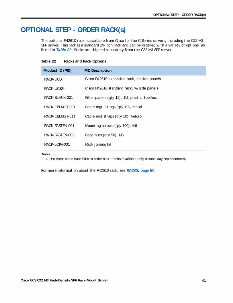
OPTIONAL STEP - ORDER RACK(s)The optional R42610 rack is available from Cisco for the C-Series servers, including the C22 M3 SFF server. This rack is a standard 19-inch rack and can be ordered with a variety of options, as listed in Table 22. Racks are shipped separately from the C22 M3 SFF server.
For more information about the R42610 rack, see RACKS, page 50.
Table 22 Racks and Rack Options
Product ID (PID) PID Description
RACK-UCS1
Notes . . .
1. Use these same base PIDs to order spare racks (available only as next-day replacements).
Cisco R42610 expansion rack, no side panels
RACK-UCS21 Cisco R42610 standard rack, w/side panels
RACK-BLANK-001 Filler panels (qty 12), 1U, plastic, toolless
RACK-CBLMGT-001 Cable mgt D rings (qty 10), metal
RACK-CBLMGT-011 Cable mgt straps (qty 10), Velcro
RACK-FASTEN-001 Mounting screws (qty 100), M6
RACK-FASTEN-002 Cage nuts (qty 50), M6
RACK-JOIN-001 Rack joining kit
Cisco UCS C22 M3 High-Density SFF Rack-Mount Server 41
OPTIONAL STEP - ORDER PDU
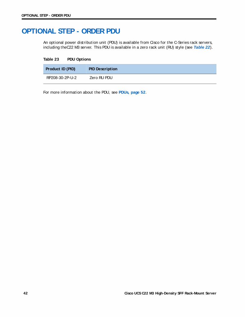
OPTIONAL STEP - ORDER PDUAn optional power distribution unit (PDU) is available from Cisco for the C-Series rack servers, including theC22 M3 server. This PDU is available in a zero rack unit (RU) style (see Table 22).
For more information about the PDU, see PDUs, page 52.
Table 23 PDU Options
Product ID (PID) PID Description
RP208-30-2P-U-2 Zero RU PDU
Cisco UCS C22 M3 High-Density SFF Rack-Mount Server42
SUPPLEMENTAL MATERIAL
SUPPLEMENTAL MATERIAL
CHASSIS
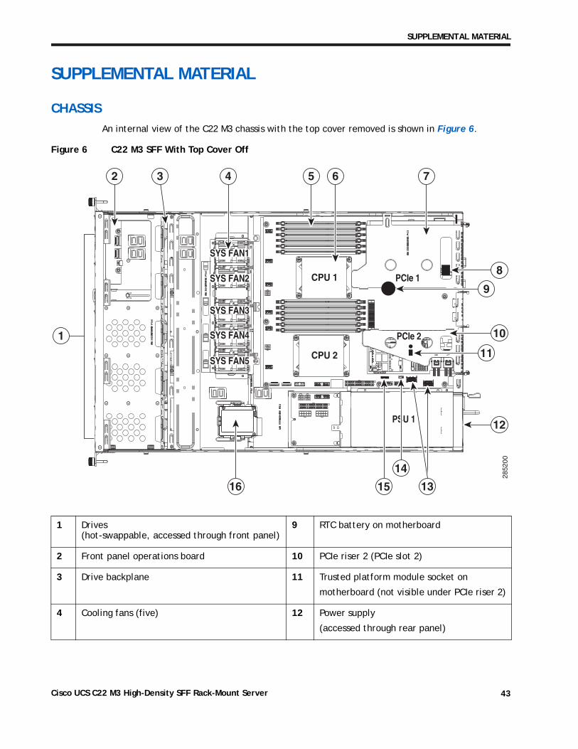
An internal view of the C22 M3 chassis with the top cover removed is shown in Figure 6.
Figure 6 C22 M3 SFF With Top Cover Off
1 Drives (hot-swappable, accessed through front panel)
9 RTC battery on motherboard
2 Front panel operations board 10 PCIe riser 2 (PCIe slot 2)
3 Drive backplane 11 Trusted platform module socket on
motherboard (not visible under PCIe riser 2)
4 Cooling fans (five) 12 Power supply
(accessed through rear panel)
PCIe 1
PCIe 2
SYS FAN1
SYS FAN2
SYS FAN3
SYS FAN4
CPU 1
CPU 2SYS FAN5
2852
00
PSU 1
1
2 3 5 74 6
8
12
10
9
11
13
14
1516
Cisco UCS C22 M3 High-Density SFF Rack-Mount Server 43
SUPPLEMENTAL MATERIAL
CPUs and DIMMs
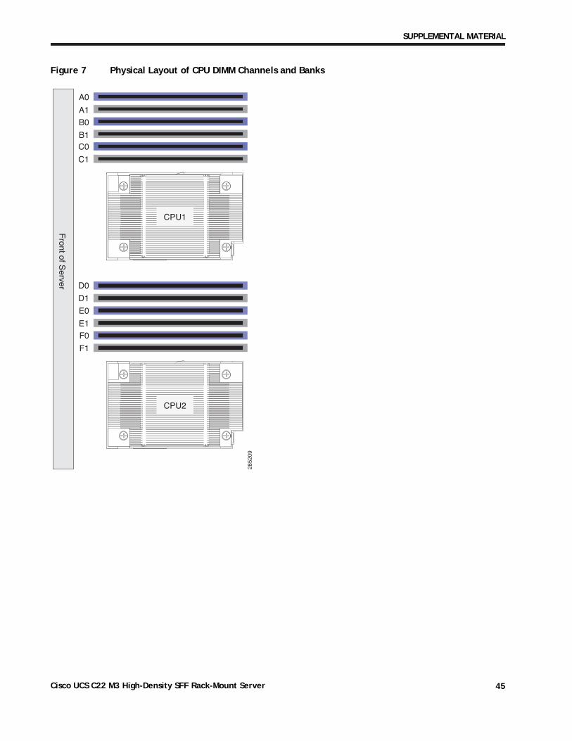
Physical Layout
Each CPU has three DIMM channels:
■ CPU1 has channels A, B, and C
■ CPU2 has channels D, E, and F
Each DIMM channel has two banks: Bank 0 and Bank 1. The blue-colored DIMM banks are for Bank 0 and the black-colored are for Bank 1.
As an example, DIMM slots A0, B0, and C0 belong to Bank 0, while A1, B1, and C1 belong to Bank 1.
Figure 7 shows how banks and channels are physically laid out on the motherboard. The DIMM slots on the top (channels A, B, and C) are associated with CPU 1, while the DIMM slots on the bottom (channels D, E, and F) are associated with CPU 2. Bank 0 slots (blue) are populated before Bank 1 slots (black).
5 DIMM slots on motherboard (12) 13 Integrated SAS RAID connectors on motherboard
(left to right, SCU_Port 0, SCU_Port 1)
6 CPU and heatsinks (2) 14 Software RAID 5 key header on motherboard
7 PCIe riser 1 (PCIe slot 1) 15 RAID SCU option ROM header on motherboard
8 Internal USB 2.0 port
(on motherboard under PCIe riser 1)
16 Mounting point for SuperCap power module (RAID backup unit)
Cisco UCS C22 M3 High-Density SFF Rack-Mount Server44
SUPPLEMENTAL MATERIAL
Figure 7 Physical Layout of CPU DIMM Channels and Banks
2852
09
A0
A1
B0
B1C0
C1
D0
D1
E0
E1F0
F1
Front of S
erver
CPU1
CPU2
Cisco UCS C22 M3 High-Density SFF Rack-Mount Server 45
SUPPLEMENTAL MATERIAL
Memory Population Rules
When considering the memory configuration of your server, you should consider the following items:
■ Each channel has two DIMM slots (for example, channel A = slots A0 and A1).
— Each channel can operate with one or two DIMMs installed.
— If a channel has only one DIMM, populate slot 0 first (the blue slot).
■ When both CPUs are installed, populate the DIMM slots of each CPU identically.
— Fill blue slots in the channels first: A0, D0, B0, E0, C0, F0
— Fill black slots in the channels second: A1, D1, B1, E1, C1, F1
■ Any DIMM installed in a DIMM socket for which the CPU is absent is not recognized.
■ For optimum performance, populate at least one DIMM per memory channel per CPU.
■ When populating DIMM slots, multiples of 6 DIMMs are best for achieving optimum performance, since there are 3 memory channels per CPU socket and 2 CPUs must be populated.
■ At 1 DPC and 2 DPC, 1600-MHz DIMMS will run at 1600 MHz (provided the CPU supports 1600 MHz DIMMs) and 1333-MHz DIMMs will run at 1333 MHz.
■ When mixing DIMMs, the following rules need to be followed:
— When mixing DIMMs of different densities (sizes), populate DIMMs with the highest density first. For example, if you have to mix 16 GB with 8 GB DIMMs, populate 16 GB DIMMs in blue slots (or bank 0) and then 8 GB in black slots (or bank 1).
— When mixing DIMMs with different ranks, populate DIMMs with the higher rank first. For example, populate 16 GB 2R or 8 GB 2R before 4 GB 1R DIMMs.
— DIMMs of different sizes (4 GB, 8 GB, 16 GB) can be mixed across different channels. Total memory size in a single channel should be the same. For example, if you are mixing 4 GB and 8 GB DIMMs to achieve total 72 GB (6x8 GB + 6x4 GB) for a server, then populate blue slots with 8 GB DIMMs and black slots with 4 GB DIMMs and total memory size should be 12 GB across all 3 channels for both CPUs.
— When mixing DIMMs, all the DIMMs in the server must be the same speed.
Cisco UCS C22 M3 High-Density SFF Rack-Mount Server46
SUPPLEMENTAL MATERIAL
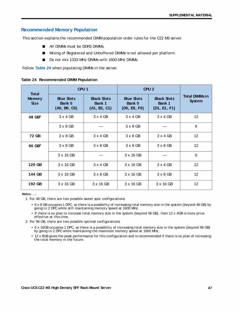
Recommended Memory Population
This section explains the recommended DIMM population order rules for the C22 M3 server.
■ All DIMMs must be DDR3 DIMMs.
■ Mixing of Registered and Unbuffered DIMMs is not allowed per platform.
■ Do not mix 1333-MHz DIMMs with 1600-MHz DIMMs.
Follow Table 24 when populating DIMMs in the server.
Table 24 Recommended DIMM Population
Total Memory
Size
CPU 1 CPU 2
Total DIMMs in System
Blue Slots Bank 0
(A0, B0, C0)
Black Slots Bank 1
(A1, B1, C1)
Blue Slots Bank 0
(D0, E0, F0)
Black Slots Bank 1
(D1, E1, F1)
48 GB1
Notes . . .
1. For 48 GB, there are two possible sweet spot configurations:
• 6 x 8 GB occupies 1 DPC, so there is a possibility of increasing total memory size in the system (beyond 48 GB) by going to 2 DPC while still maintaining memory speed at 1600 MHz.
• If there is no plan to increase total memory size in the system (beyond 48 GB), then 12 x 4GB is more price effective at this time.
3 x 4 GB 3 x 4 GB 3 x 4 GB 3 x 4 GB 12
3 x 8 GB — 3 x 8 GB — 6
72 GB 3 x 8 GB 3 x 4 GB 3 x 8 GB 3 x 4 GB 12
96 GB2
2. For 96 GB, there are two possible optimal configurations:
• 6 x 16GB occupies 1 DPC, so there is a possibility of increasing total memory size in the system (beyond 96 GB) by going to 2 DPC while maintaining the maximum memory speed at 1600 MHz.
• 12 x 8GB gives the peak performance for this configuration and is recommended if there is no plan of increasing the total memory in the future.
3 x 8 GB 3 x 8 GB 3 x 8 GB 3 x 8 GB 12
3 x 16 GB — 3 x 16 GB — 6
120 GB 3 x 16 GB 3 x 4 GB 3 x 16 GB 3 x 4 GB 12
144 GB 3 x 16 GB 3 x 8 GB 3 x 16 GB 3 x 8 GB 12
192 GB 3 x 16 GB 3 x 16 GB 3 x 16 GB 3 x 16 GB 12
Cisco UCS C22 M3 High-Density SFF Rack-Mount Server 47
SUPPLEMENTAL MATERIAL
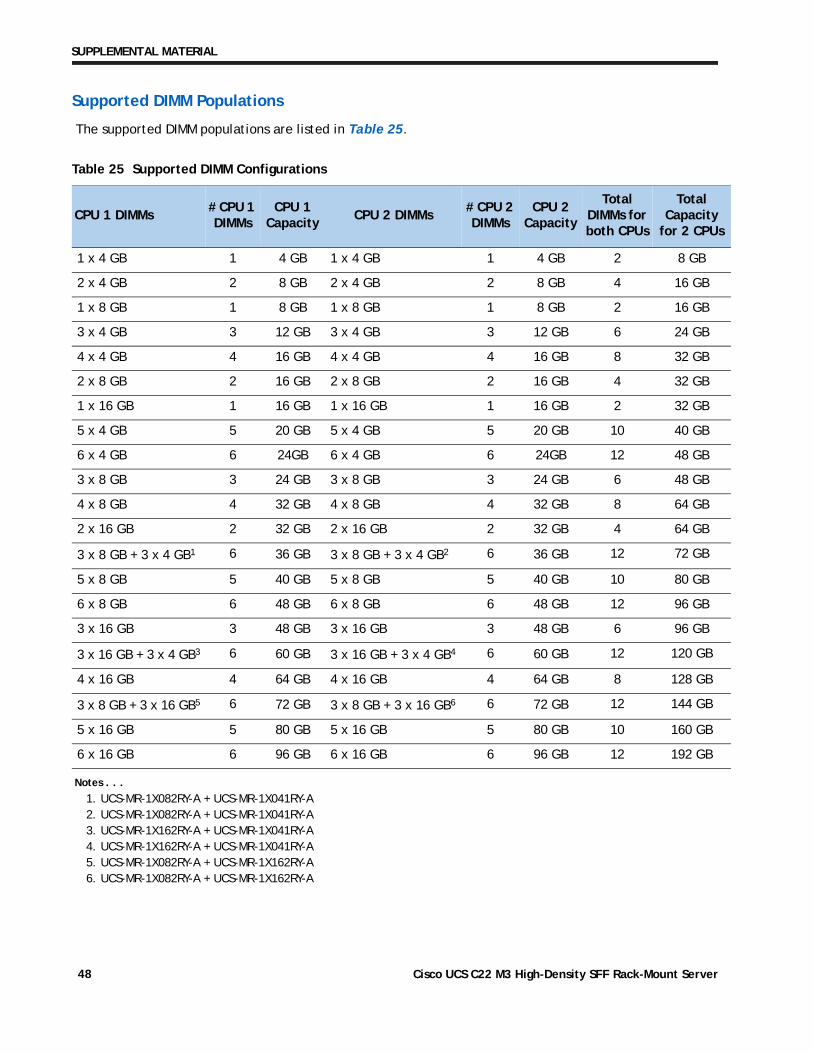
Supported DIMM Populations
The supported DIMM populations are listed in Table 25.
Table 25 Supported DIMM Configurations
CPU 1 DIMMs# CPU 1 DIMMs
CPU 1 Capacity
CPU 2 DIMMs# CPU 2 DIMMs
CPU 2 Capacity
Total DIMMs for both CPUs
Total Capacity
for 2 CPUs
1 x 4 GB 1 4 GB 1 x 4 GB 1 4 GB 2 8 GB
2 x 4 GB 2 8 GB 2 x 4 GB 2 8 GB 4 16 GB
1 x 8 GB 1 8 GB 1 x 8 GB 1 8 GB 2 16 GB
3 x 4 GB 3 12 GB 3 x 4 GB 3 12 GB 6 24 GB
4 x 4 GB 4 16 GB 4 x 4 GB 4 16 GB 8 32 GB
2 x 8 GB 2 16 GB 2 x 8 GB 2 16 GB 4 32 GB
1 x 16 GB 1 16 GB 1 x 16 GB 1 16 GB 2 32 GB
5 x 4 GB 5 20 GB 5 x 4 GB 5 20 GB 10 40 GB
6 x 4 GB 6 24GB 6 x 4 GB 6 24GB 12 48 GB
3 x 8 GB 3 24 GB 3 x 8 GB 3 24 GB 6 48 GB
4 x 8 GB 4 32 GB 4 x 8 GB 4 32 GB 8 64 GB
2 x 16 GB 2 32 GB 2 x 16 GB 2 32 GB 4 64 GB
3 x 8 GB + 3 x 4 GB1
Notes . . .
1. UCS-MR-1X082RY-A + UCS-MR-1X041RY-A
6 36 GB 3 x 8 GB + 3 x 4 GB2
2. UCS-MR-1X082RY-A + UCS-MR-1X041RY-A
6 36 GB 12 72 GB
5 x 8 GB 5 40 GB 5 x 8 GB 5 40 GB 10 80 GB
6 x 8 GB 6 48 GB 6 x 8 GB 6 48 GB 12 96 GB
3 x 16 GB 3 48 GB 3 x 16 GB 3 48 GB 6 96 GB
3 x 16 GB + 3 x 4 GB3
3. UCS-MR-1X162RY-A + UCS-MR-1X041RY-A
6 60 GB 3 x 16 GB + 3 x 4 GB4
4. UCS-MR-1X162RY-A + UCS-MR-1X041RY-A
6 60 GB 12 120 GB
4 x 16 GB 4 64 GB 4 x 16 GB 4 64 GB 8 128 GB
3 x 8 GB + 3 x 16 GB5
5. UCS-MR-1X082RY-A + UCS-MR-1X162RY-A
6 72 GB 3 x 8 GB + 3 x 16 GB6
6. UCS-MR-1X082RY-A + UCS-MR-1X162RY-A
6 72 GB 12 144 GB
5 x 16 GB 5 80 GB 5 x 16 GB 5 80 GB 10 160 GB
6 x 16 GB 6 96 GB 6 x 16 GB 6 96 GB 12 192 GB
Cisco UCS C22 M3 High-Density SFF Rack-Mount Server48
SUPPLEMENTAL MATERIAL
Low-Voltage DIMM Considerations
The C22 M3 server can be ordered with low-voltage (1.35 V) DIMMs only. Note the following considerations:
■ Low-voltage DIMMs within the server must have the identical manufacturer, type, speed, and size.
■ Low-voltage DIMMs and standard-voltage DIMMs can be mixed in the same server. Note that this causes the system BIOS to default to standard-voltage operation (Performance Mode). That is, the server cannot operate in Power Saving Mode unless all DIMMs are low-voltage DIMMs.
■ CPUs that have a maximum memory frequency less than 1333 MHz support low-voltage DIMMs operating in Power Saving Mode only, and do not support Performance Mode.
Cisco UCS C22 M3 High-Density SFF Rack-Mount Server 49
SUPPLEMENTAL MATERIAL
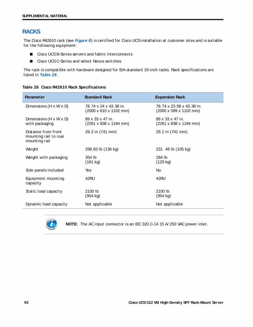
RACKS
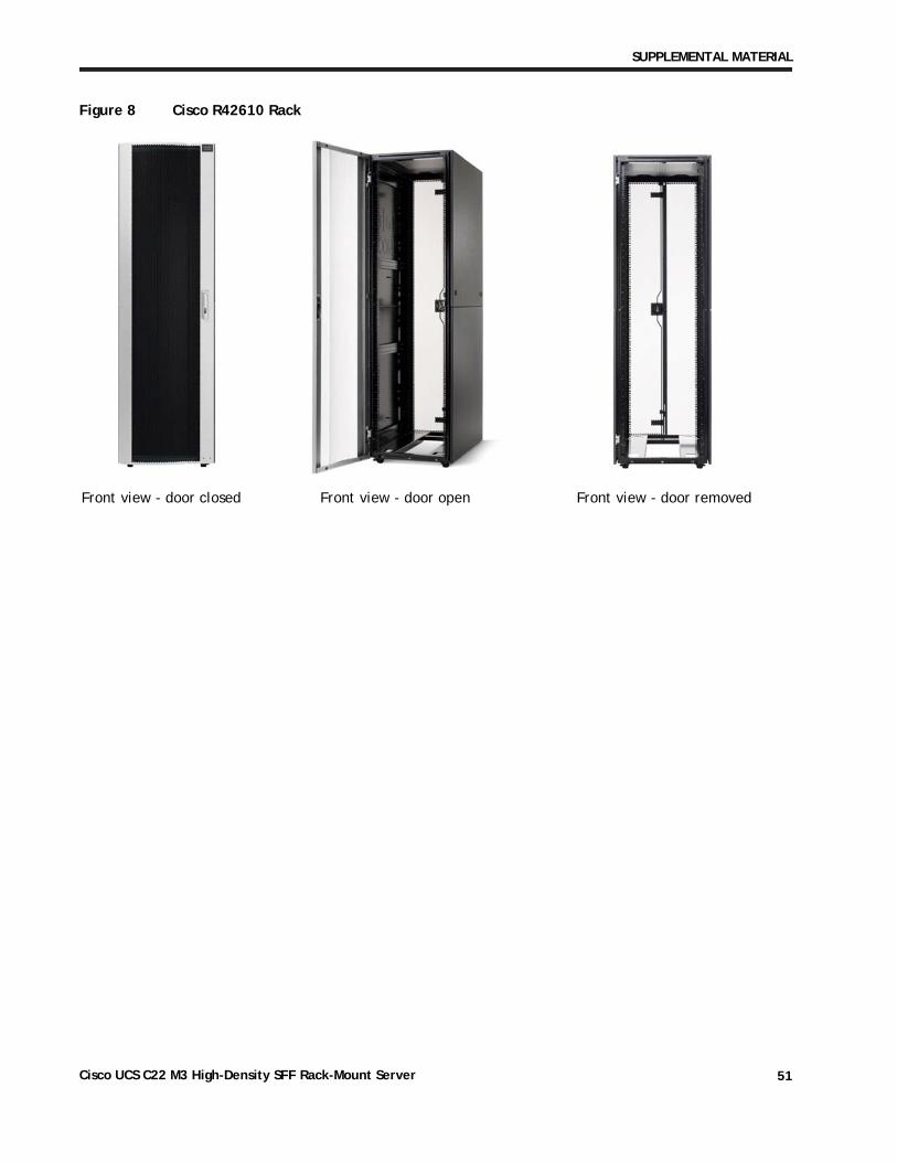
The Cisco R42610 rack (see Figure 8) is certified for Cisco UCS installation at customer sites and is suitable for the following equipment:
■ Cisco UCS B-Series servers and fabric interconnects
■ Cisco UCS C-Series and select Nexus switches
The rack is compatible with hardware designed for EIA-standard 19-inch racks. Rack specifications are listed in Table 26.
Table 26 Cisco R42610 Rack Specifications
Parameter Standard Rack Expansion Rack
Dimensions (H x W x D) 78.74 x 24 x 43.38 in. (2000 x 610 x 1102 mm)
78.74 x 23.58 x 43.38 in. (2000 x 599 x 1102 mm)
Dimensions (H x W x D) with packaging
89 x 33 x 47 in. (2261 x 838 x 1194 mm)
89 x 33 x 47 in. (2261 x 838 x 1194 mm)
Distance from front mounting rail to rear mounting rail
29.2 in (741 mm) 29.2 in (741 mm)
Weight 299.83 lb (136 kg) 231. 49 lb (105 kg)
Weight with packaging 354 lb (161 kg)
284 lb (129 kg)
Side panels included Yes No
Equipment mounting capacity
42RU 42RU
Static load capacity 2100 lb (954 kg)
2100 lb (954 kg)
Dynamic load capacity Not applicable Not applicable
NOTE: The AC input connector is an IEC 320 C-14 15 A/250 VAC power inlet.
Cisco UCS C22 M3 High-Density SFF Rack-Mount Server50
SUPPLEMENTAL MATERIAL
Figure 8 Cisco R42610 Rack
Front view - door closed Front view - door open Front view - door removed
Cisco UCS C22 M3 High-Density SFF Rack-Mount Server 51
SUPPLEMENTAL MATERIAL
PDUs
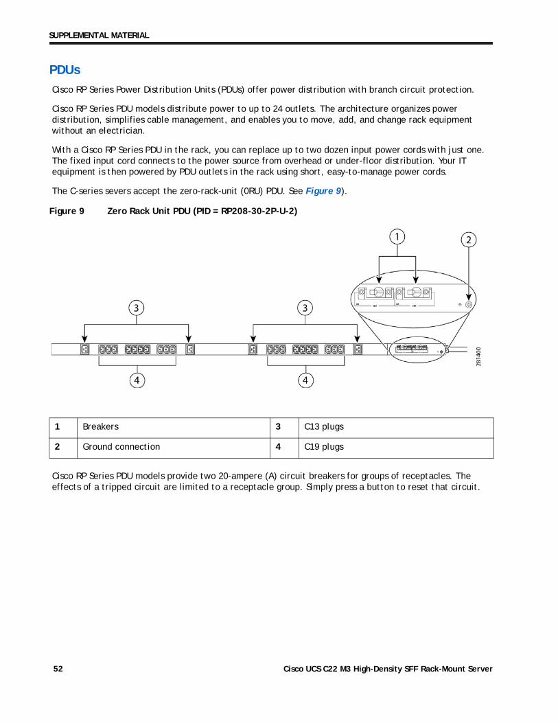
Cisco RP Series Power Distribution Units (PDUs) offer power distribution with branch circuit protection.
Cisco RP Series PDU models distribute power to up to 24 outlets. The architecture organizes power distribution, simplifies cable management, and enables you to move, add, and change rack equipment without an electrician.
With a Cisco RP Series PDU in the rack, you can replace up to two dozen input power cords with just one. The fixed input cord connects to the power source from overhead or under-floor distribution. Your IT equipment is then powered by PDU outlets in the rack using short, easy-to-manage power cords.
The C-series severs accept the zero-rack-unit (0RU) PDU. See Figure 9).
Figure 9 Zero Rack Unit PDU (PID = RP208-30-2P-U-2)
Cisco RP Series PDU models provide two 20-ampere (A) circuit breakers for groups of receptacles. The effects of a tripped circuit are limited to a receptacle group. Simply press a button to reset that circuit.
1 Breakers 3 C13 plugs
2 Ground connection 4 C19 plugs
Cisco UCS C22 M3 High-Density SFF Rack-Mount Server52
SUPPLEMENTAL MATERIAL
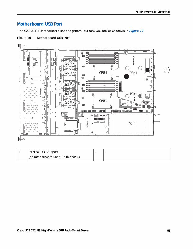
Motherboard USB Port
The C22 M3 SFF motherboard has one general-purpose USB socket as shown in Figure 10.
Figure 10 Motherboard USB Port
1 Internal USB 2.0 port
(on motherboard under PCIe riser 1)
- -
PCIe 1
PCIe 2
SYS FAN1
SYS FAN2
SYS FAN3
SYS FAN4
CPU 1
CPU 2SYS FAN5
PSU 1
1
Cisco UCS C22 M3 High-Density SFF Rack-Mount Server 53
SUPPLEMENTAL MATERIAL
LED Indicators
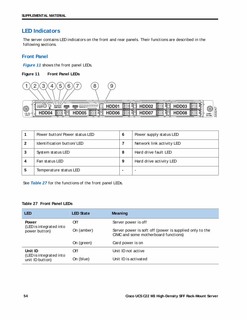
The server contains LED indicators on the front and rear panels. Their functions are described in the following sections.
Front Panel
Figure 11 shows the front panel LEDs.
Figure 11 Front Panel LEDs
See Table 27 for the functions of the front panel LEDs.
1 Power button/Power status LED 6 Power supply status LED
2 Identification button/LED 7 Network link activity LED
3 System status LED 8 Hard drive fault LED
4 Fan status LED 9 Hard drive activity LED
5 Temperature status LED - -
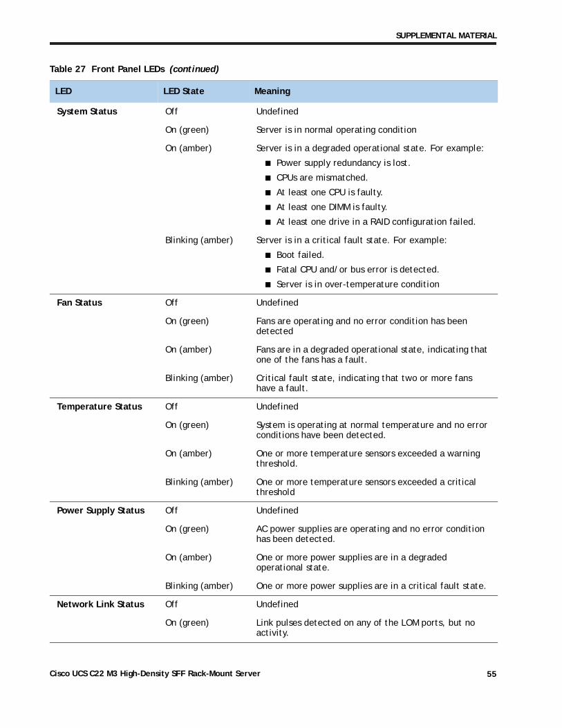
Table 27 Front Panel LEDs
LED LED State Meaning
Power (LED is integrated into power button)
Off Server power is off
On (amber) Server power is soft off (power is supplied only to the CIMC and some motherboard functions)
On (green) Card power is on
Unit ID (LED is integrated into unit ID button)
Off Unit ID not active
On (blue) Unit ID is activated
HDD06HDD01
HDD07HDD02
HDD08HDD03
HDD04HDD04HDD04 HDD05HDD05HDD05
1 2 3 4 5 6 7 8 9
3332
47
Cisco UCS C22 M3 High-Density SFF Rack-Mount Server54
SUPPLEMENTAL MATERIAL
System Status Off Undefined
On (green) Server is in normal operating condition
On (amber) Server is in a degraded operational state. For example:
■ Power supply redundancy is lost.
■ CPUs are mismatched.
■ At least one CPU is faulty.
■ At least one DIMM is faulty.
■ At least one drive in a RAID configuration failed.
Blinking (amber) Server is in a critical fault state. For example:
■ Boot failed.
■ Fatal CPU and/or bus error is detected.
■ Server is in over-temperature condition
Fan Status Off Undefined
On (green) Fans are operating and no error condition has been detected
On (amber) Fans are in a degraded operational state, indicating that one of the fans has a fault.
Blinking (amber) Critical fault state, indicating that two or more fans have a fault.
Temperature Status Off Undefined
On (green) System is operating at normal temperature and no error conditions have been detected.
On (amber) One or more temperature sensors exceeded a warning threshold.
Blinking (amber) One or more temperature sensors exceeded a critical threshold
Power Supply Status Off Undefined
On (green) AC power supplies are operating and no error condition has been detected.
On (amber) One or more power supplies are in a degraded operational state.
Blinking (amber) One or more power supplies are in a critical fault state.
Network Link Status Off Undefined
On (green) Link pulses detected on any of the LOM ports, but no activity.
Table 27 Front Panel LEDs (continued)
LED LED State Meaning
Cisco UCS C22 M3 High-Density SFF Rack-Mount Server 55
SUPPLEMENTAL MATERIAL
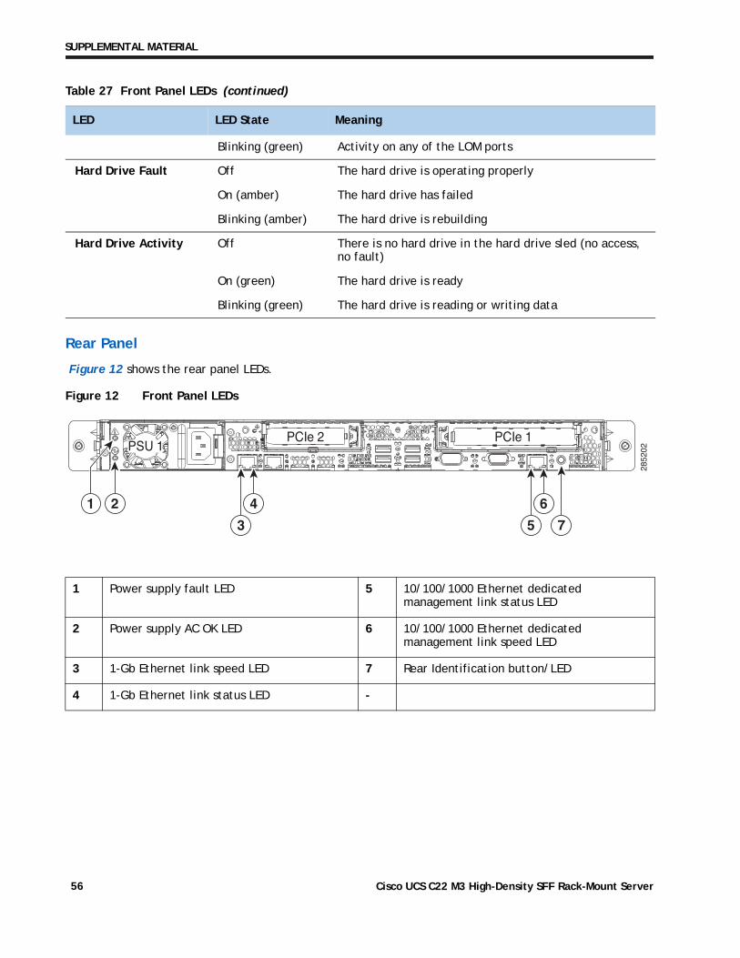
Rear Panel
Figure 12 shows the rear panel LEDs.
Figure 12 Front Panel LEDs
Blinking (green) Activity on any of the LOM ports
Hard Drive Fault Off The hard drive is operating properly
On (amber) The hard drive has failed
Blinking (amber) The hard drive is rebuilding
Hard Drive Activity Off There is no hard drive in the hard drive sled (no access, no fault)
On (green) The hard drive is ready
Blinking (green) The hard drive is reading or writing data
1 Power supply fault LED 5 10/100/1000 Ethernet dedicated management link status LED
2 Power supply AC OK LED 6 10/100/1000 Ethernet dedicated management link speed LED
3 1-Gb Ethernet link speed LED 7 Rear Identification button/LED
4 1-Gb Ethernet link status LED -
Table 27 Front Panel LEDs (continued)
LED LED State Meaning
2852
02PSU 1PCIe 2 PCIe 1
1 2
3
4
5 7
6
Cisco UCS C22 M3 High-Density SFF Rack-Mount Server56
SUPPLEMENTAL MATERIAL
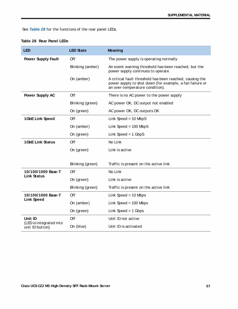
See Table 28 for the functions of the rear panel LEDs.
Table 28 Rear Panel LEDs
LED LED State Meaning
Power Supply Fault Off The power supply is operating normally
Blinking (amber) An event warning threshold has been reached, but the power supply continues to operate
On (amber) A critical fault threshold has been reached, causing the power supply to shut down (for example, a fan failure or an over-temperature condition).
Power Supply AC Off There is no AC power to the power supply
Blinking (green) AC power OK, DC output not enabled
On (green) AC power OK, DC outputs OK
1GbE Link Speed Off Link Speed = 10 MbpS
On (amber) Link Speed = 100 MbpS
On (green) Link Speed = 1 GbpS
1GbE Link Status Off No Link
On (green) Link is active
Blinking (green) Traffic is present on the active link
10/100/1000 Base-T Link Status
Off No Link
On (green) Link is active
Blinking (green) Traffic is present on the active link
10/100/1000 Base-T Link Speed
Off Link Speed = 10 Mbps
On (amber) Link Speed = 100 Mbps
On (green) Link Speed = 1 Gbps
Unit ID (LED is integrated into unit ID button)
Off Unit ID not active
On (blue) Unit ID is activated
Cisco UCS C22 M3 High-Density SFF Rack-Mount Server 57
TECHNICAL SPECIFICATIONS
TECHNICAL SPECIFICATIONS
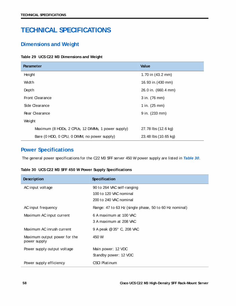
Dimensions and Weight
Power Specifications
The general power specifications for the C22 M3 SFF server 450 W power supply are listed in Table 30.
Table 29 UCS C22 M3 Dimensions and Weight
Parameter Value
Height 1.70 in (43.2 mm)
Width 16.93 in.(430 mm)
Depth 26.0 in. (660.4 mm)
Front Clearance 3 in. (76 mm)
Side Clearance 1 in. (25 mm)
Rear Clearance 9 in. (233 mm)
Weight
Maximum (8 HDDs, 2 CPUs, 12 DIMMs, 1 power supply) 27.78 lbs (12.6 kg)
Bare (0 HDD, 0 CPU, 0 DIMM, no power supply) 23.48 lbs (10.65 kg)
Table 30 UCS C22 M3 SFF 450 W Power Supply Specifications
Description Specification
AC input voltage 90 to 264 VAC self-ranging
100 to 120 VAC nominal
200 to 240 VAC nominal
AC input frequency Range: 47 to 63 Hz (single phase, 50 to 60 Hz nominal)
Maximum AC input current 6 A maximum at 100 VAC
3 A maximum at 208 VAC
Maximum AC inrush current 9 A peak @ 35° C, 208 VAC
Maximum output power for the power supply
450 W
Power supply output voltage Main power: 12 VDC
Standby power: 12 VDC
Power supply efficiency CSCI Platinum
Cisco UCS C22 M3 High-Density SFF Rack-Mount Server58
TECHNICAL SPECIFICATIONS
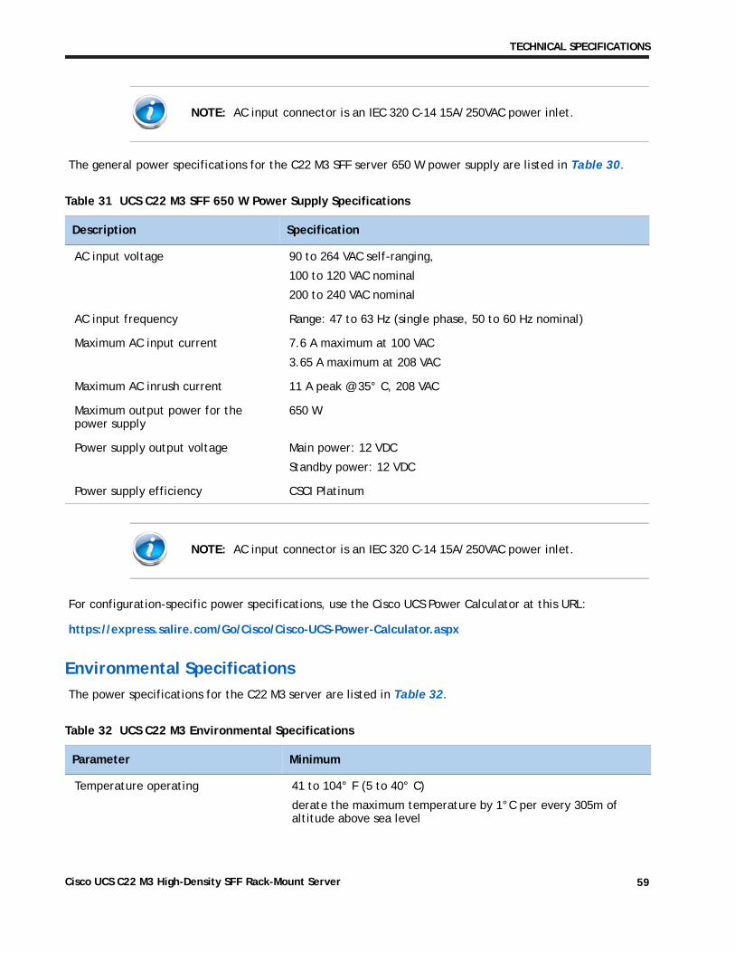
The general power specifications for the C22 M3 SFF server 650 W power supply are listed in Table 30.
For configuration-specific power specifications, use the Cisco UCS Power Calculator at this URL:
https://express.salire.com/Go/Cisco/Cisco-UCS-Power-Calculator.aspx
Environmental Specifications
The power specifications for the C22 M3 server are listed in Table 32.
NOTE: AC input connector is an IEC 320 C-14 15A/250VAC power inlet.
Table 31 UCS C22 M3 SFF 650 W Power Supply Specifications
Description Specification
AC input voltage 90 to 264 VAC self-ranging,
100 to 120 VAC nominal
200 to 240 VAC nominal
AC input frequency Range: 47 to 63 Hz (single phase, 50 to 60 Hz nominal)
Maximum AC input current 7.6 A maximum at 100 VAC
3.65 A maximum at 208 VAC
Maximum AC inrush current 11 A peak @ 35° C, 208 VAC
Maximum output power for the power supply
650 W
Power supply output voltage Main power: 12 VDC
Standby power: 12 VDC
Power supply efficiency CSCI Platinum
NOTE: AC input connector is an IEC 320 C-14 15A/250VAC power inlet.
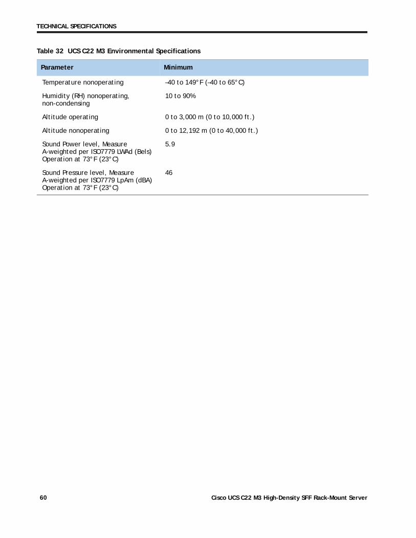
Table 32 UCS C22 M3 Environmental Specifications
Parameter Minimum
Temperature operating 41 to 104° F (5 to 40° C)
derate the maximum temperature by 1°C per every 305m of altitude above sea level
Cisco UCS C22 M3 High-Density SFF Rack-Mount Server 59
TECHNICAL SPECIFICATIONS
Temperature nonoperating –40 to 149°F (–40 to 65°C)
Humidity (RH) nonoperating, non-condensing
10 to 90%
Altitude operating 0 to 3,000 m (0 to 10,000 ft.)
Altitude nonoperating 0 to 12,192 m (0 to 40,000 ft.)
Sound Power level, Measure A-weighted per ISO7779 LWAd (Bels) Operation at 73°F (23°C)
5.9
Sound Pressure level, Measure A-weighted per ISO7779 LpAm (dBA) Operation at 73°F (23°C)
46
Table 32 UCS C22 M3 Environmental Specifications
Parameter Minimum
Cisco UCS C22 M3 High-Density SFF Rack-Mount Server60
TECHNICAL SPECIFICATIONS
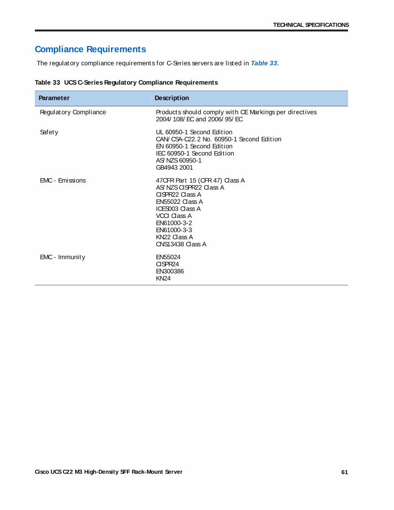
Compliance Requirements
The regulatory compliance requirements for C-Series servers are listed in Table 33.
Table 33 UCS C-Series Regulatory Compliance Requirements
Parameter Description
Regulatory Compliance Products should comply with CE Markings per directives 2004/108/EC and 2006/95/EC
Safety UL 60950-1 Second Edition CAN/CSA-C22.2 No. 60950-1 Second Edition EN 60950-1 Second Edition IEC 60950-1 Second Edition AS/NZS 60950-1 GB4943 2001
EMC - Emissions 47CFR Part 15 (CFR 47) Class A AS/NZS CISPR22 Class A CISPR22 Class A EN55022 Class A ICES003 Class A VCCI Class A EN61000-3-2 EN61000-3-3 KN22 Class A CNS13438 Class A
EMC - Immunity EN55024 CISPR24 EN300386 KN24
Cisco UCS C22 M3 High-Density SFF Rack-Mount Server 61
TECHNICAL SPECIFICATIONS
Cisco UCS C22 M3 High-Density SFF Rack-Mount Server62