Cisco TrustSec How-To Guide: Universal Configuration for the Cisco Wireless … · Configuring...
21
Cisco TrustSec How-To Guide: Universal Configuration for the Cisco Wireless LAN Controller For Comments, please email: [email protected] Current Document Version: 3.0 August 27, 2012
Transcript of Cisco TrustSec How-To Guide: Universal Configuration for the Cisco Wireless … · Configuring...
Cisco TrustSec How-To Guide: Universal Configuration for the Cisco Wireless LAN Controller
For Comments, please email: [email protected]
Current Document Version: 3.0
August 27, 2012
HowTo-11-Universal WLC Config.docx 2
Table of Contents
Table of Contents ........................................................................................................................... 1
Introduction ................................................................................................................................... 3
What Is the Cisco TrustSec System? ............................................................................................................................................................................................................................... 3 About the TrustSec How-To Guides ............................................................................................................................................................................................................................... 3
What does it mean to be ‘TrustSec Certified’? ......................................................................................................................................................................................................................... 4
Universal Configuration for the Cisco Wireless LAN Controller .................................................... 5
Initial Configuration for the Cisco WLC ..................................................................................................................................................................................................................................... 5 Adding 802.1X and Central Web Authentication SSIDs ....................................................................................................................................................................................................14 Configuring Cisco ISE for Wireless Authentication .............................................................................................................................................................................................................19
Appendix A: References .............................................................................................................. 21
Cisco TrustSec System: ..................................................................................................................................................................................................................................................... 21 Device Configuration Guides: ........................................................................................................................................................................................................................................ 21
HowTo-11-Universal WLC Config.docx 3
Introduction
What Is the Cisco TrustSec System?
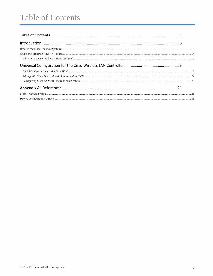
Cisco TrustSec®, a core component of the Cisco SecureX Architecture™, is an intelligent access control solution. Cisco
TrustSec mitigates security risks by providing comprehensive visibility into who and what is connecting across the entire
network infrastructure, and exceptional control over what and where they can go.
TrustSec builds on your existing identity-aware access layer infrastructure (switches, wireless controllers, and so on). The
solution and all the components within the solution are thoroughly vetted and rigorously tested as an integrated system.
In addition to combining standards-based identity and enforcement models, such as IEEE 802.1X and VLAN control, the
Cisco TrustSec system it also includes advanced identity and enforcement capabilities such as flexible authentication,
Downloadable Access Control Lists (dACLs), Security Group Tagging (SGT), device profiling, posture assessments, and
more.
Figure 1: Cisco TrustSec Architecture Overview
About the TrustSec How-To Guides
The TrustSec team is producing this series of How-To documents to describe best practices for Cisco TrustSec deployments.
The documents in the series build on one another and guide the reader through a successful implementation of the Cisco
TrustSec system. You can use these documents to follow the prescribed path to deploy the entire system, or simply pick the
single use-case that meets your specific need.
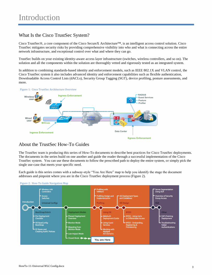
Each guide is this series comes with a subway-style “You Are Here” map to help you identify the stage the document
addresses and pinpoint where you are in the Cisco TrustSec deployment process (Figure 2).
Figure 2: How-To Guide Navigation Map
SXP
Data Center
Wireless user
Campus Network Wired
user
Egress Enforcement
MACsec
Profiler
Posture
Guest Services
Security
Gro
up Tag
RADIUS
Ingress Enforcement
Ingress Enforcement
Security
Group Tag
HowTo-11-Universal WLC Config.docx 4
What does it mean to be ‘TrustSec Certified’?
Each TrustSec version number (for example, Cisco TrustSec Version 2.0, Version 2.1, and so on) is a certified design or
architecture. All the technology making up the architecture has undergone thorough architectural design development and
lab testing. For a How-To Guide to be marked “TrustSec certified,” all the elements discussed in the document must meet
the following criteria:
Products incorporated in the design must be generally available.
Deployment, operation, and management of components within the system must exhibit repeatable processes.
All configurations and products used in the design must have been fully tested as an integrated solution.
Many features may exist that could benefit your deployment, but if they were not part of the tested solution, they will not be
marked as “Cisco TrustSec “certified”. The Cisco TrustSec team strives to provide regular updates to these documents that
will include new features as they become available, and are integrated into the Cisco TrustSec test plans, pilot deployments,
and system revisions. (i.e., Cisco TrustSec 2.2 certification).
Additionally, many features and scenarios have been tested, but are not considered a best practice, and therefore are not
included in these documents. As an example, certain IEEE 802.1X timers and local web authentication features are not
included.
Note: Within this document, we describe the recommended method of deployment, and a few different options depending on the level of security needed in your environment. These methods are examples and step-by-step instructions for Cisco TrustSec deployment as prescribed by Cisco best practices to help ensure a successful project deployment.
HowTo-11-Universal WLC Config.docx 5
Universal Configuration for the Cisco Wireless
LAN Controller
The following section describes the “universal configuration” for Cisco® Wireless LAN Controllers (WLC). These
recommended configurations are compiled as a best practice to be used for all deployments, and they remain consistent
through the different stages of deployment, as well as the different deployment types chosen.
Initial Configuration for the Cisco WLC
Procedure 1 Bootstrap the Wireless LAN Controller
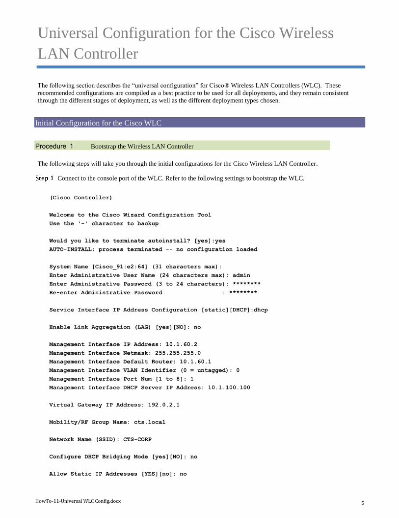
The following steps will take you through the initial configurations for the Cisco Wireless LAN Controller.
Connect to the console port of the WLC. Refer to the following settings to bootstrap the WLC.
(Cisco Controller)
Welcome to the Cisco Wizard Configuration Tool
Use the '-' character to backup
Would you like to terminate autoinstall? [yes]:yes
AUTO-INSTALL: process terminated -- no configuration loaded
System Name [Cisco_91:e2:64] (31 characters max):
Enter Administrative User Name (24 characters max): admin
Enter Administrative Password (3 to 24 characters): ********
Re-enter Administrative Password : ********
Service Interface IP Address Configuration [static][DHCP]:dhcp
Enable Link Aggregation (LAG) [yes][NO]: no
Management Interface IP Address: 10.1.60.2
Management Interface Netmask: 255.255.255.0
Management Interface Default Router: 10.1.60.1
Management Interface VLAN Identifier (0 = untagged): 0
Management Interface Port Num [1 to 8]: 1
Management Interface DHCP Server IP Address: 10.1.100.100
Virtual Gateway IP Address: 192.0.2.1
Mobility/RF Group Name: cts.local
Network Name (SSID): CTS-CORP
Configure DHCP Bridging Mode [yes][NO]: no
Allow Static IP Addresses [YES][no]: no
HowTo-11-Universal WLC Config.docx 6
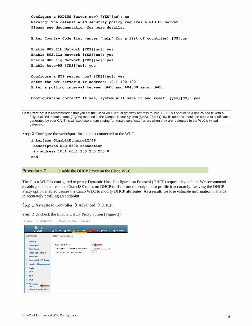
Configure a RADIUS Server now? [YES][no]: no
Warning! The default WLAN security policy requires a RADIUS server.
Please see documentation for more details.
Enter Country Code list (enter 'help' for a list of countries) [US]:us
Enable 802.11b Network [YES][no]: yes
Enable 802.11a Network [YES][no]: yes
Enable 802.11g Network [YES][no]: yes
Enable Auto-RF [YES][no]: yes
Configure a NTP server now? [YES][no]: yes
Enter the NTP server's IP address: 10.1.100.100
Enter a polling interval between 3600 and 604800 secs: 3600
Configuration correct? If yes, system will save it and reset. [yes][NO]: yes
Best Practice: It is recommended that you set the Cisco WLC virtual gateway address to 192.0.2.1. This should be a non-routed IP with a fully qualified domain name (FQDN) mapped in the Domain Name System (DNS). This FQDN/ IP address should be added to certificates generated by your CA. This will stop users from seeing “untrusted certificate” errors when they are redirected to the WLC’s virtual gateway.
Configure the switchport for the port connected to the WLC.
interface GigabitEthernet2/46
description WLC-5500 connection
ip address 10.1.60.1 255.255.255.0
end
Procedure 2 Disable the DHCP Proxy on the Cisco WLC
The Cisco WLC is configured to proxy Dynamic Host Configuration Protocol (DHCP) requests by default. We recommend
disabling this feature since Cisco ISE relies on DHCP traffic from the endpoint to profile it accurately. Leaving the DHCP
Proxy option enabled causes the Cisco WLC to modify DHCP attributes. As a result, we lose valuable information that aids
in accurately profiling an endpoint.
Navigate to Controller Advanced DHCP.
Uncheck the Enable DHCP Proxy option (Figure 3).
Figure 3 Disabling DHCP Proxy on the Cisco WLC
HowTo-11-Universal WLC Config.docx 7
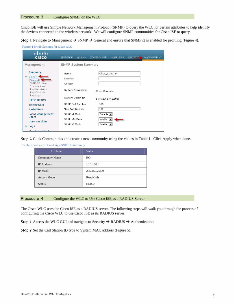
Procedure 3 Configure SNMP on the WLC
Cisco ISE will use Simple Network Management Protocol (SNMP) to query the WLC for certain attributes to help identify
the devices connected to the wireless network. We will configure SNMP communities for Cisco ISE to query.
Navigate to Management SNMP General and ensure that SNMPv2 is enabled for profiling (Figure 4).
Figure 4 SNMP Settings for Cisco WLC
Click Communities and create a new community using the values in Table 1. Click Apply when done.
Table 1: Values for Creating a SNMP Community
Attribute Value
Community Name RO
IP Address 10.1.100.0
IP Mask 255.255.255.0
Access Mode Read Only
Status Enable
Procedure 4 Configure the WLC to Use Cisco ISE as a RADIUS Server
The Cisco WLC uses the Cisco ISE as a RADIUS server. The following steps will walk you through the process of
configuring the Cisco WLC to use Cisco ISE as its RADIUS server.
Access the WLC GUI and navigate to Security RADIUS Authentication.
Set the Call Station ID type to System MAC address (Figure 5).
HowTo-11-Universal WLC Config.docx 8
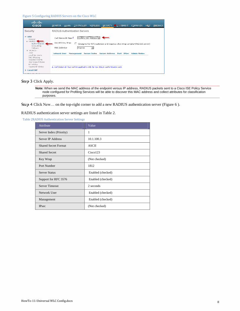
Figure 5 Configuring RADIUS Servers on the Cisco WLC
Click Apply.
Note: When we send the MAC address of the endpoint versus IP address, RADIUS packets sent to a Cisco ISE Policy Service node configured for Profiling Services will be able to discover this MAC address and collect attributes for classification purposes.
Click New… on the top-right corner to add a new RADIUS authentication server (Figure 6 ).
RADIUS authentication server settings are listed in Table 2.
Table 2RADIUS Authentication Server Settings
Attribute Value
Server Index (Priority) 1
Server IP Address 10.1.100.3
Shared Secret Format ASCII
Shared Secret Cisco123
Key Wrap (Not checked)
Port Number 1812
Server Status Enabled (checked)
Support for RFC 3576 Enabled (checked)
Server Timeout 2 seconds
Network User Enabled (checked)
Management Enabled (checked)
IPsec (Not checked)
HowTo-11-Universal WLC Config.docx 9
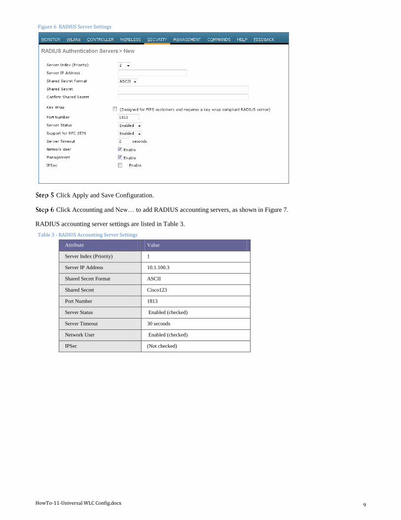
Figure 6 RADIUS Server Settings
Click Apply and Save Configuration.
Click Accounting and New… to add RADIUS accounting servers, as shown in Figure 7.
RADIUS accounting server settings are listed in Table 3.
Table 3 - RADIUS Accounting Server Settings
Attribute Value
Server Index (Priority) 1
Server IP Address 10.1.100.3
Shared Secret Format ASCII
Shared Secret Cisco123
Port Number 1813
Server Status Enabled (checked)
Server Timeout 30 seconds
Network User Enabled (checked)
IPSec (Not checked)
HowTo-11-Universal WLC Config.docx 10
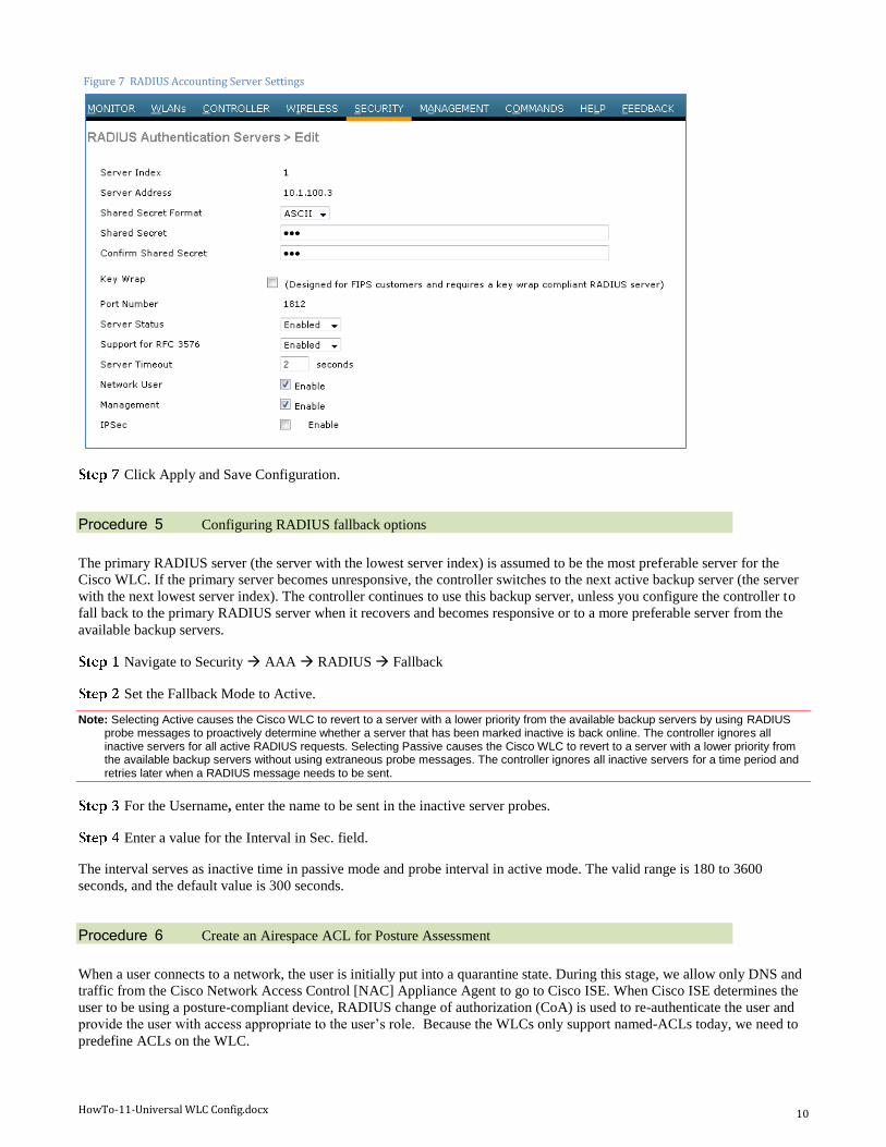
Figure 7 RADIUS Accounting Server Settings
Click Apply and Save Configuration.
Procedure 5 Configuring RADIUS fallback options
The primary RADIUS server (the server with the lowest server index) is assumed to be the most preferable server for the
Cisco WLC. If the primary server becomes unresponsive, the controller switches to the next active backup server (the server
with the next lowest server index). The controller continues to use this backup server, unless you configure the controller to
fall back to the primary RADIUS server when it recovers and becomes responsive or to a more preferable server from the
available backup servers.
Navigate to Security AAA RADIUS Fallback
Set the Fallback Mode to Active.
Note: Selecting Active causes the Cisco WLC to revert to a server with a lower priority from the available backup servers by using RADIUS probe messages to proactively determine whether a server that has been marked inactive is back online. The controller ignores all inactive servers for all active RADIUS requests. Selecting Passive causes the Cisco WLC to revert to a server with a lower priority from the available backup servers without using extraneous probe messages. The controller ignores all inactive servers for a time period and retries later when a RADIUS message needs to be sent.
For the Username, enter the name to be sent in the inactive server probes.
Enter a value for the Interval in Sec. field.
The interval serves as inactive time in passive mode and probe interval in active mode. The valid range is 180 to 3600
seconds, and the default value is 300 seconds.
Procedure 6 Create an Airespace ACL for Posture Assessment
When a user connects to a network, the user is initially put into a quarantine state. During this stage, we allow only DNS and
traffic from the Cisco Network Access Control [NAC] Appliance Agent to go to Cisco ISE. When Cisco ISE determines the
user to be using a posture-compliant device, RADIUS change of authorization (CoA) is used to re-authenticate the user and
provide the user with access appropriate to the user’s role. Because the WLCs only support named-ACLs today, we need to
predefine ACLs on the WLC.
HowTo-11-Universal WLC Config.docx 11
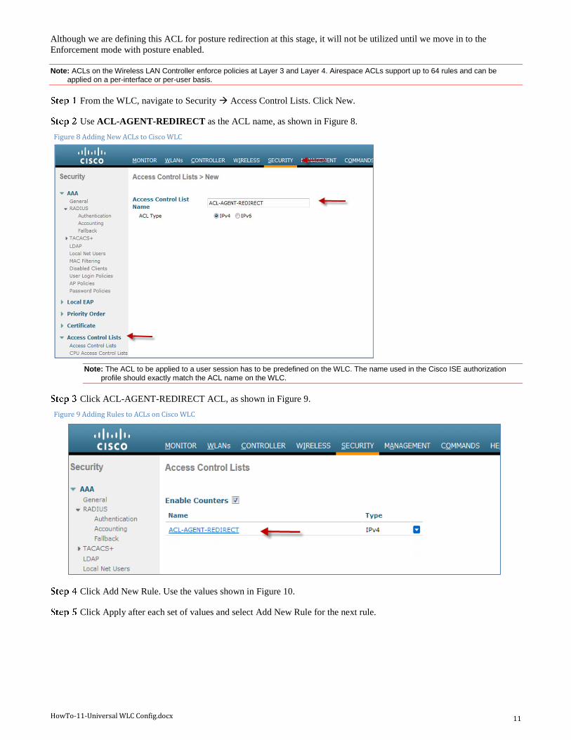
Although we are defining this ACL for posture redirection at this stage, it will not be utilized until we move in to the
Enforcement mode with posture enabled.
Note: ACLs on the Wireless LAN Controller enforce policies at Layer 3 and Layer 4. Airespace ACLs support up to 64 rules and can be applied on a per-interface or per-user basis.
From the WLC, navigate to Security Access Control Lists. Click New.
Use ACL-AGENT-REDIRECT as the ACL name, as shown in Figure 8.
Figure 8 Adding New ACLs to Cisco WLC
Note: The ACL to be applied to a user session has to be predefined on the WLC. The name used in the Cisco ISE authorization
profile should exactly match the ACL name on the WLC.
Click ACL-AGENT-REDIRECT ACL, as shown in Figure 9.
Figure 9 Adding Rules to ACLs on Cisco WLC
Click Add New Rule. Use the values shown in Figure 10.
Click Apply after each set of values and select Add New Rule for the next rule.
HowTo-11-Universal WLC Config.docx 12
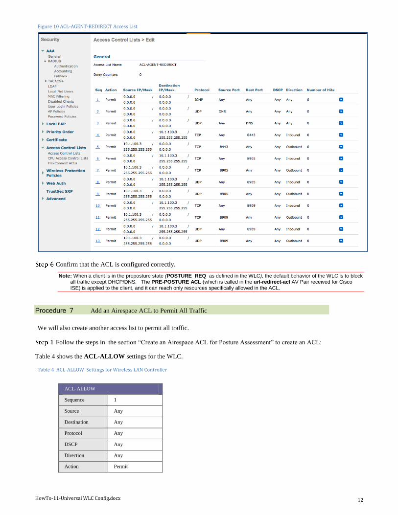
Figure 10 ACL-AGENT-REDIRECT Access List
Confirm that the ACL is configured correctly.
Note: When a client is in the preposture state (POSTURE_REQ as defined in the WLC), the default behavior of the WLC is to block all traffic except DHCP/DNS. The PRE-POSTURE ACL (which is called in the url-redirect-acl AV Pair received for Cisco ISE) is applied to the client, and it can reach only resources specifically allowed in the ACL.
Procedure 7 Add an Airespace ACL to Permit All Traffic
We will also create another access list to permit all traffic.
Follow the steps in the section “Create an Airespace ACL for Posture Assessment” to create an ACL:
Table 4 shows the ACL-ALLOW settings for the WLC.
Table 4 ACL-ALLOW Settings for Wireless LAN Controller
ACL-ALLOW
Sequence 1
Source Any
Destination Any
Protocol Any
DSCP Any
Direction Any
Action Permit
HowTo-11-Universal WLC Config.docx 13
Procedure 8 Create Dynamic Interfaces for the Employee and Guest VLANs
We will be creating two different Service Set IDs (SSIDs) for wireless networks. One will be used for employees and the
other for guests. Each SSID can be mapped to an individual dynamic interface. The following steps will walk you through
the process of creating dynamic interfaces on the Cisco WLC.
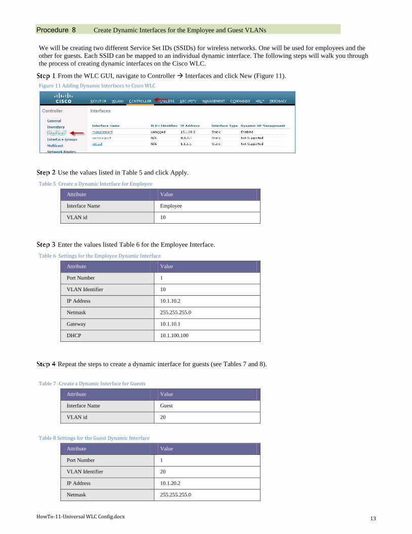
From the WLC GUI, navigate to Controller Interfaces and click New (Figure 11).
Figure 11 Adding Dynamic Interfaces to Cisco WLC
Use the values listed in Table 5 and click Apply.
Table 5 Create a Dynamic Interface for Employee
Attribute Value
Interface Name Employee
VLAN id 10
Enter the values listed Table 6 for the Employee Interface.
Table 6 Settings for the Employee Dynamic Interface
Attribute Value
Port Number 1
VLAN Identifier 10
IP Address 10.1.10.2
Netmask 255.255.255.0
Gateway 10.1.10.1
DHCP 10.1.100.100
Repeat the steps to create a dynamic interface for guests (see Tables 7 and 8).
Table 7 -Create a Dynamic Interface for Guests
Attribute Value
Interface Name Guest
VLAN id 20
Table 8 Settings for the Guest Dynamic Interface
Attribute Value
Port Number 1
VLAN Identifier 20
IP Address 10.1.20.2
Netmask 255.255.255.0
HowTo-11-Universal WLC Config.docx 14
Gateway 10.1.20.1
DHCP 10.1.100.100
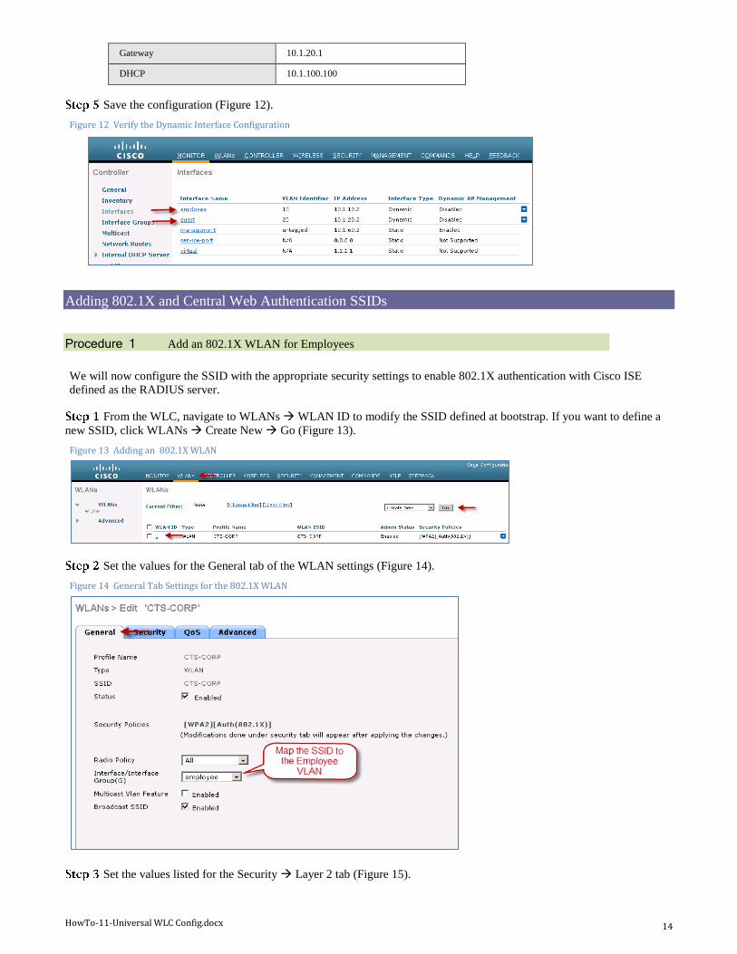
Save the configuration (Figure 12).
Figure 12 Verify the Dynamic Interface Configuration
Adding 802.1X and Central Web Authentication SSIDs
Procedure 1 Add an 802.1X WLAN for Employees
We will now configure the SSID with the appropriate security settings to enable 802.1X authentication with Cisco ISE
defined as the RADIUS server.
From the WLC, navigate to WLANs WLAN ID to modify the SSID defined at bootstrap. If you want to define a
new SSID, click WLANs Create New Go (Figure 13).
Figure 13 Adding an 802.1X WLAN
Set the values for the General tab of the WLAN settings (Figure 14).
Figure 14 General Tab Settings for the 802.1X WLAN
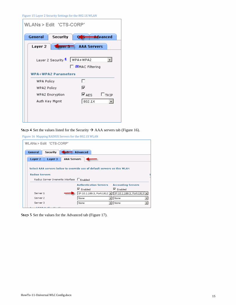
Set the values listed for the Security Layer 2 tab (Figure 15).
HowTo-11-Universal WLC Config.docx 15
Figure 15 Layer 2 Security Settings for the 802.1X WLAN
Set the values listed for the Security AAA servers tab (Figure 16).
Figure 16 Mapping RADIUS Servers for the 802.1X WLAN
Set the values for the Advanced tab (Figure 17).
HowTo-11-Universal WLC Config.docx 16
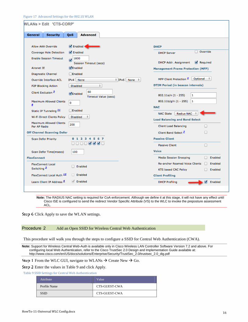
Figure 17 Advanced Settings for the 802.1X WLAN
Note: The RADIUS NAC setting is required for CoA enforcement. Although we define it at this stage, it will not have any effect until Cisco ISE is configured to send the redirect Vendor Specific Attribute (VS) to the WLC to invoke the preposture assessment ACL.
Click Apply to save the WLAN settings.
Procedure 2 Add an Open SSID for Wireless Central Web Authentication
This procedure will walk you through the steps to configure a SSID for Central Web Authentication (CWA).
Note: Support for Wireless Central Web-Auth is available only in Cisco Wireless LAN Controller Software Version 7.2 and above. For configuring local Web Authentication, refer to the Cisco TrustSec 2.0 Design and Implementation Guide available at: http://www.cisco.com/en/US/docs/solutions/Enterprise/Security/TrustSec_2.0/trustsec_2.0_dig.pdf
From the WLC GUI, navigate to WLANs Create New Go.
Enter the values in Table 9 and click Apply.
Table 9 SSID Settings for Central Web Authentication
Attribute Value
Profile Name CTS-GUEST-CWA
SSID CTS-GUEST-CWA
HowTo-11-Universal WLC Config.docx 17
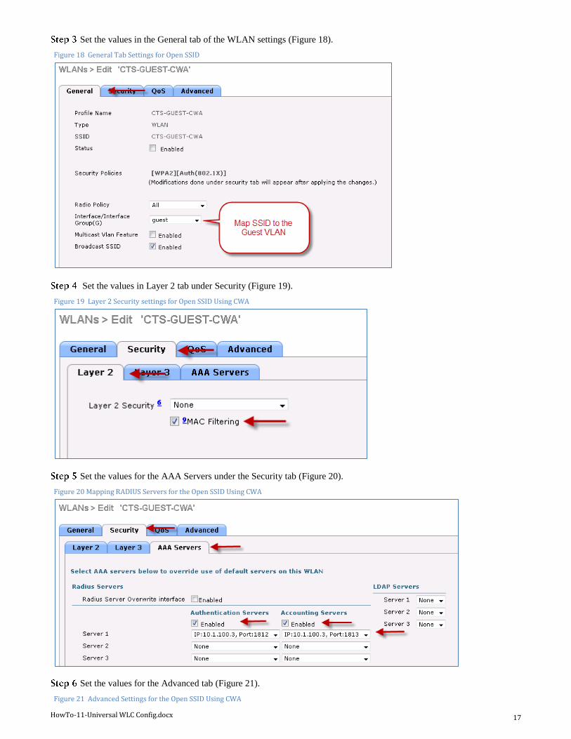
Set the values in the General tab of the WLAN settings (Figure 18).
Figure 18 General Tab Settings for Open SSID
Set the values in Layer 2 tab under Security (Figure 19).
Figure 19 Layer 2 Security settings for Open SSID Using CWA
Set the values for the AAA Servers under the Security tab (Figure 20).
Figure 20 Mapping RADIUS Servers for the Open SSID Using CWA
Set the values for the Advanced tab (Figure 21).
Figure 21 Advanced Settings for the Open SSID Using CWA
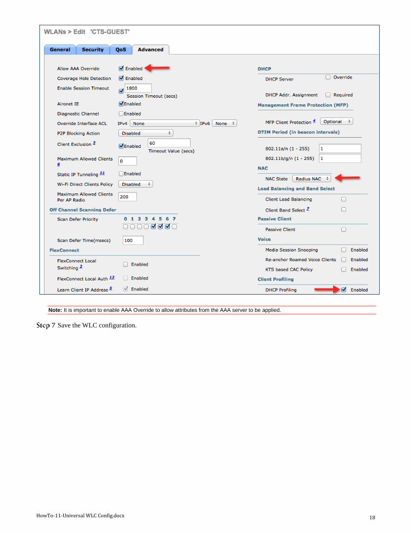
HowTo-11-Universal WLC Config.docx 18
Note: It is important to enable AAA Override to allow attributes from the AAA server to be applied.
Save the WLC configuration.
HowTo-11-Universal WLC Config.docx 19
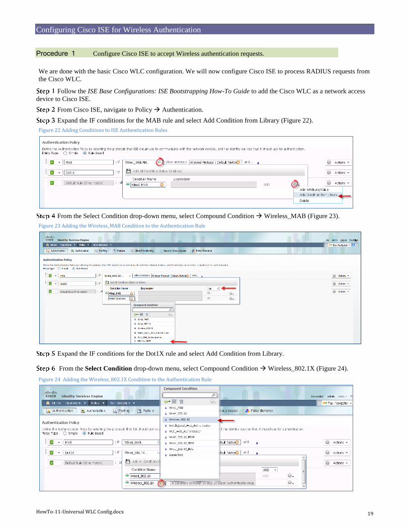
Configuring Cisco ISE for Wireless Authentication
Procedure 1 Configure Cisco ISE to accept Wireless authentication requests.
We are done with the basic Cisco WLC configuration. We will now configure Cisco ISE to process RADIUS requests from
the Cisco WLC.
Follow the ISE Base Configurations: ISE Bootstrapping How-To Guide to add the Cisco WLC as a network access
device to Cisco ISE.
From Cisco ISE, navigate to Policy Authentication.
Expand the IF conditions for the MAB rule and select Add Condition from Library (Figure 22).
Figure 22 Adding Conditions to ISE Authentication Rules
From the Select Condition drop-down menu, select Compound Condition Wireless_MAB (Figure 23).
Figure 23 Adding the Wireless_MAB Condition to the Authentication Rule
Expand the IF conditions for the Dot1X rule and select Add Condition from Library.
From the Select Condition drop-down menu, select Compound Condition Wireless_802.1X (Figure 24).
Figure 24 Adding the Wireless_802.1X Condition to the Authentication Rule
HowTo-11-Universal WLC Config.docx 20
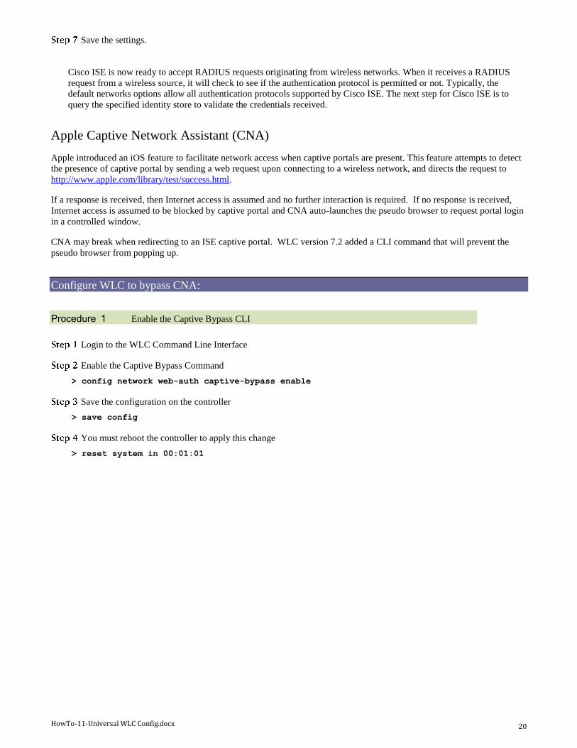
Save the settings.
Cisco ISE is now ready to accept RADIUS requests originating from wireless networks. When it receives a RADIUS
request from a wireless source, it will check to see if the authentication protocol is permitted or not. Typically, the
default networks options allow all authentication protocols supported by Cisco ISE. The next step for Cisco ISE is to
query the specified identity store to validate the credentials received.
Apple Captive Network Assistant (CNA)
Apple introduced an iOS feature to facilitate network access when captive portals are present. This feature attempts to detect
the presence of captive portal by sending a web request upon connecting to a wireless network, and directs the request to
http://www.apple.com/library/test/success.html.
If a response is received, then Internet access is assumed and no further interaction is required. If no response is received,
Internet access is assumed to be blocked by captive portal and CNA auto-launches the pseudo browser to request portal login
in a controlled window.
CNA may break when redirecting to an ISE captive portal. WLC version 7.2 added a CLI command that will prevent the
pseudo browser from popping up.
Configure WLC to bypass CNA:
Procedure 1 Enable the Captive Bypass CLI
Login to the WLC Command Line Interface
Enable the Captive Bypass Command
> config network web-auth captive-bypass enable
Save the configuration on the controller
> save config
You must reboot the controller to apply this change
> reset system in 00:01:01
HowTo-11-Universal WLC Config.docx 21
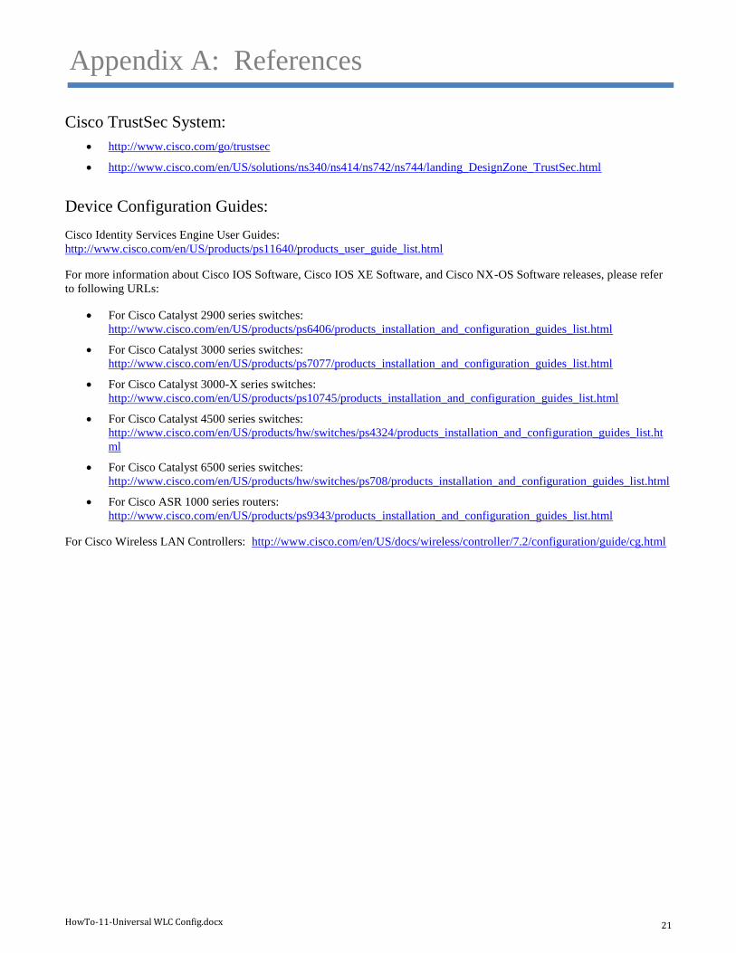
Appendix A: References
Cisco TrustSec System:
http://www.cisco.com/go/trustsec
http://www.cisco.com/en/US/solutions/ns340/ns414/ns742/ns744/landing_DesignZone_TrustSec.html
Device Configuration Guides:
Cisco Identity Services Engine User Guides:
http://www.cisco.com/en/US/products/ps11640/products_user_guide_list.html
For more information about Cisco IOS Software, Cisco IOS XE Software, and Cisco NX-OS Software releases, please refer
to following URLs:
For Cisco Catalyst 2900 series switches:
http://www.cisco.com/en/US/products/ps6406/products_installation_and_configuration_guides_list.html
For Cisco Catalyst 3000 series switches:
http://www.cisco.com/en/US/products/ps7077/products_installation_and_configuration_guides_list.html
For Cisco Catalyst 3000-X series switches:
http://www.cisco.com/en/US/products/ps10745/products_installation_and_configuration_guides_list.html
For Cisco Catalyst 4500 series switches:
http://www.cisco.com/en/US/products/hw/switches/ps4324/products_installation_and_configuration_guides_list.ht
ml
For Cisco Catalyst 6500 series switches:
http://www.cisco.com/en/US/products/hw/switches/ps708/products_installation_and_configuration_guides_list.html
For Cisco ASR 1000 series routers:
http://www.cisco.com/en/US/products/ps9343/products_installation_and_configuration_guides_list.html
For Cisco Wireless LAN Controllers: http://www.cisco.com/en/US/docs/wireless/controller/7.2/configuration/guide/cg.html