Cisco Nexus B22 Blade Fabric Extender for · PDF fileThe Cisco Nexus® B22 Blade Fabric...
70
© 2014 Cisco | IBM. All rights reserved. Page 1 Cisco Nexus B22 Blade Fabric Extender for IBM Design and Deployment Guide
Transcript of Cisco Nexus B22 Blade Fabric Extender for · PDF fileThe Cisco Nexus® B22 Blade Fabric...

© 2014 Cisco | IBM. All rights reserved. Page 1
Cisco Nexus B22 Blade Fabric Extender for IBM
Design and Deployment Guide
November 2013
Int
© 2014 Cisco | IBM. All rights reserved. Page 2
Contents
Introduction .............................................................................................................................................................. 3
Network Diagram ...................................................................................................................................................... 3
Hardware Installation ............................................................................................................................................... 5
Fabric Extender Management Model ..................................................................................................................... 6
Fabric Connectivity Options ................................................................................................................................... 7 Statically Pinned Fabric Interface Connection ....................................................................................................... 7 Port Channel Fabric Interface Connection ............................................................................................................ 9 Configuring a Fabric Port Channel ...................................................................................................................... 10
Virtual Port Channel Connection .......................................................................................................................... 13 Configuring a vPC ................................................................................................................................................ 14
Server Network Teaming ....................................................................................................................................... 16 Creating Host-Side vPC for Server Links with LACP .......................................................................................... 17
Fibre Channel over Ethernet ................................................................................................................................. 21 Configuring FCoE ................................................................................................................................................ 21 Configuring the Cisco Nexus 5000 Series and B22 for IBM for FCoE ................................................................ 22
iSCSI Configuration ............................................................................................................................................... 27
Virtual Network Adapter Partitioning ................................................................................................................... 30
Debug Commands ................................................................................................................................................. 35 show fex ............................................................................................................................................................... 35 show fex detail ..................................................................................................................................................... 36 show interface brief .............................................................................................................................................. 37 show interface ethernet 191/1/1 .......................................................................................................................... 42 show vlan ............................................................................................................................................................. 43 show interface fex-fabric ...................................................................................................................................... 44
Cisco Nexus Configurations ................................................................................................................................. 45 Cisco Nexus 5000 Series Switch 1 Configuration ............................................................................................... 45 Cisco Nexus 5000 Series Switch 2 Configuration ............................................................................................... 56
Conclusion .............................................................................................................................................................. 70
For More Information ............................................................................................................................................. 70
© 2014 Cisco | IBM. All rights reserved. Page 3
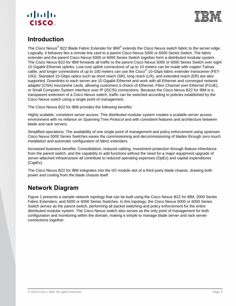
Introduction
The Cisco Nexus® B22 Blade Fabric Extender for IBM
® extends the Cisco Nexus switch fabric to the server edge.
Logically, it behaves like a remote line card to a parent Cisco Nexus 5000 or 6000 Series Switch. The fabric
extender and the parent Cisco Nexus 5000 or 6000 Series Switch together form a distributed modular system.
The Cisco Nexus B22 for IBM forwards all traffic to the parent Cisco Nexus 5000 or 6000 Series Switch over eight
10 Gigabit Ethernet uplinks. Low-cost uplink connections of up to 10 meters can be made with copper Twinax
cable, and longer connections of up to 100 meters can use the Cisco® 10-Gbps fabric extender transceiver (FET-
10G). Standard 10-Gbps optics such as short reach (SR), long reach (LR), and extended reach (ER) are also
supported. Downlinks to each server are 10 Gigabit Ethernet and work with all Ethernet and converged network
adapter (CNA) mezzanine cards, allowing customers a choice of Ethernet, Fibre Channel over Ethernet (FCoE),
or Small Computer System Interface over IP (iSCSI) connections. Because the Cisco Nexus B22 for IBM is a
transparent extension of a Cisco Nexus switch, traffic can be switched according to policies established by the
Cisco Nexus switch using a single point of management.
The Cisco Nexus B22 for IBM provides the following benefits:
Highly scalable, consistent server access: This distributed modular system creates a scalable server access
environment with no reliance on Spanning Tree Protocol and with consistent features and architecture between
blade and rack servers.
Simplified operations: The availability of one single point of management and policy enforcement using upstream
Cisco Nexus 5000 Series Switches eases the commissioning and decommissioning of blades through zero-touch
installation and automatic configuration of fabric extenders.
Increased business benefits: Consolidation, reduced cabling, investment protection through feature inheritance
from the parent switch, and the capability to add functions without the need for a major equipment upgrade of
server-attached infrastructure all contribute to reduced operating expenses (OpEx) and capital expenditures
(CapEx).
The Cisco Nexus B22 for IBM integrates into the I/O module slot of a third-party blade chassis, drawing both
power and cooling from the blade chassis itself.
Network Diagram
Figure 1 presents a sample network topology that can be built using the Cisco Nexus B22 for IBM, 2000 Series
Fabric Extenders, and 5000 or 6000 Series Switches. In this topology, the Cisco Nexus 5000 or 6000 Series
Switch serves as the parent switch, performing all packet switching and policy enforcement for the entire
distributed modular system. The Cisco Nexus switch also serves as the only point of management for both
configuration and monitoring within the domain, making it simple to manage blade server and rack server
connections together.

© 2014 Cisco | IBM. All rights reserved. Page 4
Figure 1: Cisco Nexus Virtual Chassis Topology
The Cisco Nexus switches, along with the Cisco Nexus 2000 Series and B22 for IBM, create a distributed
modular system that unifies the data center architecture. Within this distributed modular system, both IBM Flex
System® computing nodes and rack servers are managed identically. This approach allows the use of the same
business and technical processes and procedures.
The left-most blade chassis in Figure 1 contains dual Cisco Nexus B22 for IBM fabric extenders. Each Cisco
Nexus B22 for IBM is singlely attached to a parent Cisco Nexus 5500 platform switch, a connection mode referred
to as straight-through mode. The fabric links can be either statically pinned or put into a Port Channel. This
connection mode helps ensure that all data packets from a particular Cisco Nexus B22 for IBM enter the same
parent Cisco Nexus switch. This approach may be necessary when certain types of traffic must be restricted to
either the left or right Cisco Nexus 5500 platform switch: for instance, to maintain SAN A and SAN B separation.
Also, in this example the connections to individual computing nodes are in active-standby mode, which helps
ensure traffic flow consistency but does not make full use of the server network interface card (NIC) bandwidth.
The second IBM Flex System chassis from the left in Figure 1 improves on the first with the creation of an
Ethernet virtual Port Channel (vPC) from the computing node to the Cisco Nexus parent switch. This vPC places
the Ethernet portion of the NICs in an active-active configuration, giving increased bandwidth to each host. The
FCoE portion of the CNA is also configured as active-active but maintains SAN A and SAN B separation because
each virtual Fibre Channel (vFC) interface is bound to a particular link at the server. This configuration also
achieves high availability through redundancy, and it can withstand a failure of a Cisco Nexus 5500 platform
switch, a Cisco Nexus B22 for IBM, or any connecting cable. This topology is widely used in FCoE deployments.
The third blade chassis from the left in Figure 1 contains Cisco Nexus B22 for IBM fabric extenders that connect
to both Cisco Nexus 5500 platform switches through vPC for redundancy. In this configuration, active-active load
balancing using vPC from the blade server to the Cisco Nexus 5500 platform switch cannot be enabled. However,
the servers can still be dual-homed with active-standby or active-active transmit-load-balancing (TLB) teaming.
This topology is only for Ethernet traffic because SAN A and SAN B separation between the fabric extender and
the parent switch is necessary.
© 2014 Cisco | IBM. All rights reserved. Page 5
The fourth blade chassis from the left in Figure 1 contains Cisco Nexus B22 for IBM fabric extenders that connect
to both Cisco Nexus 5500 platform switches with enhanced vPC (EvPC) technology. This configuration allows
active-active load balancing from the fabric extenders and the computing nodes.
The last two configurations show how rack-mount servers can connect to the same Cisco Nexus parent switch
using rack-mount Cisco Nexus 2000 Series Fabric Extenders. The topology for blade servers and rack-mount
servers can be identical if desired.
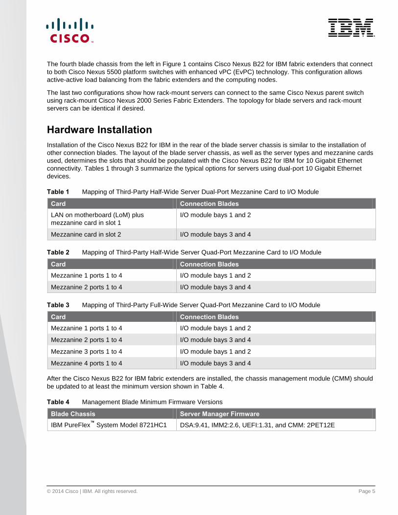
Hardware Installation
Installation of the Cisco Nexus B22 for IBM in the rear of the blade server chassis is similar to the installation of
other connection blades. The layout of the blade server chassis, as well as the server types and mezzanine cards
used, determines the slots that should be populated with the Cisco Nexus B22 for IBM for 10 Gigabit Ethernet
connectivity. Tables 1 through 3 summarize the typical options for servers using dual-port 10 Gigabit Ethernet
devices.
Table 1 Mapping of Third-Party Half-Wide Server Dual-Port Mezzanine Card to I/O Module
Card Connection Blades
LAN on motherboard (LoM) plus
mezzanine card in slot 1
I/O module bays 1 and 2
Mezzanine card in slot 2 I/O module bays 3 and 4
Table 2 Mapping of Third-Party Half-Wide Server Quad-Port Mezzanine Card to I/O Module
Card Connection Blades
Mezzanine 1 ports 1 to 4 I/O module bays 1 and 2
Mezzanine 2 ports 1 to 4 I/O module bays 3 and 4
Table 3 Mapping of Third-Party Full-Wide Server Quad-Port Mezzanine Card to I/O Module
Card Connection Blades
Mezzanine 1 ports 1 to 4 I/O module bays 1 and 2
Mezzanine 2 ports 1 to 4 I/O module bays 3 and 4
Mezzanine 3 ports 1 to 4 I/O module bays 1 and 2
Mezzanine 4 ports 1 to 4 I/O module bays 3 and 4
After the Cisco Nexus B22 for IBM fabric extenders are installed, the chassis management module (CMM) should
be updated to at least the minimum version shown in Table 4.
Table 4 Management Blade Minimum Firmware Versions
Blade Chassis Server Manager Firmware
IBM PureFlex™
System Model 8721HC1 DSA:9.41, IMM2:2.6, UEFI:1.31, and CMM: 2PET12E

© 2014 Cisco | IBM. All rights reserved. Page 6
No configuration is required from the chassis MMB. Only the minimum CMM firmware is required to properly
detect and enable the Cisco Nexus B22 for IBM in the blade chassis (Figure 2).
Figure 2: Cisco Nexus B22 for IBM Fabric Extenders as Seen in the CMM
Fabric Extender Management Model
The Cisco Nexus fabric extenders are managed by a parent switch through the fabric interfaces using a zero-
touch configuration model. The switch discovers the fabric extender by using a detection protocol.
After discovery, if the fabric extender has been correctly associated with the parent switch, the following
operations are performed:
1. The switch checks the software image compatibility and upgrades the fabric extender if necessary.
2. The switch and fabric extender establish in-band IP connectivity with each other. The switch assigns an IP
address in the range of loopback addresses (127.15.1.0/24) to the fabric extender to avoid conflicts with IP
addresses that might be in use on the network.
3. The switch pushes the configuration data to the fabric extender. The fabric extender does not store any
configuration locally.
4. The fabric extender updates the switch with its operating status. All fabric extender information is displayed
using the switch commands for monitoring and troubleshooting.
This management model allows fabric extender modules to be added without adding management points or
complexity. Software image and configuration management is also handled automatically, without the need for
user intervention.

© 2014 Cisco | IBM. All rights reserved. Page 7
Fabric Connectivity Options
The Cisco Nexus B22 for IBM creates a distributed, modular chassis with the Cisco Nexus parent switch after a
fabric connection has been made over standard 10-Gbps cabling. This connection can be accomplished using
any of the following types of interconnects:
Cisco passive direct-attach cables (1m, 3m, or 5m)
Cisco active direct-attach cables (7m or 10m)
Cisco standard Enhanced Small Form-Factor Pluggable (SFP+) optics (SR, LR, and ER)
Cisco Fabric Extender Transceivers (FET modules)
After the fabric links have been physically established, the logical configuration of the links must be established.
The fabric links to the Cisco Nexus B22 for IBM can use either of two connection methods:
Statically pinned fabric interface connection
Port Channel fabric interface connection
Statically Pinned Fabric Interface Connection
Static pinning is the default method of connection between the fabric extender and the Cisco Nexus parent switch.
In this mode of operation, a deterministic relationship exists between the host interfaces and the upstream parent;
up to eight fabric interfaces can be connected. These fabric interfaces are equally divided among the 16 server-
side host ports. If fewer fabric ports are allocated, more server ports are assigned to a single fabric link. The
advantage of this configuration is that the traffic path and the amount of allocated bandwidth are always known for
a particular set of servers.
Since static pinning will group host-side ports into individual fabric links, you should understand how ports are
grouped. The size of the port groups is determined by the number of host ports divided by the max link
parameter value. For example, if the max link parameter is set to 2, eight host ports would be assigned to each
link. The interfaces will be grouped in ascending order starting from interface 1. Thus, interfaces 1 to 8 will be
pinned to one fabric link, and interfaces 9 to 16 will be pinned to a different interface (Table 5).
Table 5 Interface Assignment with Two Fabric Links
Interface Fabric Link
1, 2, 3, 4, 5, 6, and 7 Fabric link 1
8, 9, 10, 11, 12, 13, and 14 Fabric link 2
© 2014 Cisco | IBM. All rights reserved. Page 8
Table 6 summarizes the assignment with four fabric links: With the max link parameter set to 4, the interfaces are
divided into four groups.
Table 6 Interface Assignment with Four Fabric Links
Interface Fabric Link
1, 2, 3, and 4 Fabric link 1
5, 6, 7, and 8 Fabric link 2
9, 10, and 11 Fabric link 3
12, 13, and 14 Fabric link 4
Table 7 summarizes the assignment of eight fabric links: With the max link parameter set to 8, the interfaces are
divided into eight groups.
Table 7 Interface Assignment with Eight Fabric Links
Interface Fabric Link
1 and 2 Fabric link 1
3 and 4 Fabric link 2
5 and 6 Fabric link 3
7 and 8 Fabric link 4
9 and 10 Fabric link 5
11 and 12 Fabric link 6
13 Fabric link 7
14 Fabric link 8
Note: The assignment of the host-side ports is always based on the configured max link parameter and not the actual
physical number of fabric ports connected. Be sure to match the max link parameter with the actual number of
physical links used.

© 2014 Cisco | IBM. All rights reserved. Page 9
The relationship of host-side ports to parent switch fabric ports is static. If a fabric interface fails, all its associated
host interfaces are brought down and will remain down until the fabric interface is restored. Figure 3 shows static
port mappings.
Figure 3: Static Port Mapping Based on Max Link Parameter
Port Channel Fabric Interface Connection
The Port Channel fabric interface provides an alternative way of connecting the parent switch and the Cisco
Nexus B22 for IBM fabric extender. In this mode of operation, the physical fabric links are bundled into a single
logical channel. This approach prevents a single fabric interconnect link loss from disrupting traffic to any one
server. The total bandwidth of the logical channel is shared by all the servers, and traffic is spread across the
members through the use of a hash algorithm.
For a Layer 2 frame, the switch uses the source and destination MAC addresses.
For a Layer 3 frame, the switch uses the source and destination MAC addresses and the source and
destination IP addresses.
Since both redundancy and increased bandwidth are possible, configuration of the fabric links on a Port Channel
is the most popular connection option.
© 2014 Cisco | IBM. All rights reserved. Page 10
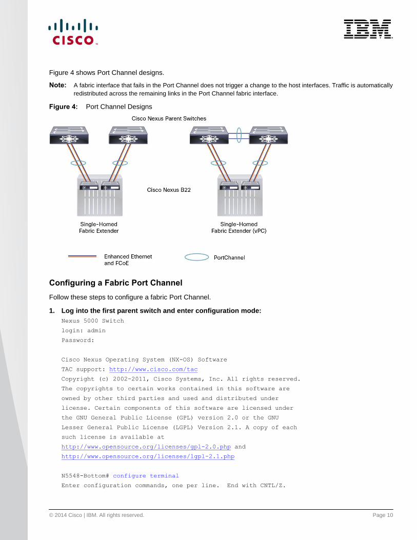
Figure 4 shows Port Channel designs.
Note: A fabric interface that fails in the Port Channel does not trigger a change to the host interfaces. Traffic is automatically
redistributed across the remaining links in the Port Channel fabric interface.
Figure 4: Port Channel Designs
Configuring a Fabric Port Channel
Follow these steps to configure a fabric Port Channel.
1. Log into the first parent switch and enter configuration mode:
Nexus 5000 Switch
login: admin
Password:
Cisco Nexus Operating System (NX-OS) Software
TAC support: http://www.cisco.com/tac
Copyright (c) 2002-2011, Cisco Systems, Inc. All rights reserved.
The copyrights to certain works contained in this software are
owned by other third parties and used and distributed under
license. Certain components of this software are licensed under
the GNU General Public License (GPL) version 2.0 or the GNU
Lesser General Public License (LGPL) Version 2.1. A copy of each
such license is available at
http://www.opensource.org/licenses/gpl-2.0.php and
http://www.opensource.org/licenses/lgpl-2.1.php
N5548-Bottom# configure terminal
Enter configuration commands, one per line. End with CNTL/Z.

© 2014 Cisco | IBM. All rights reserved. Page 11
N5548-Bottom(config)#
2. Enable the fabric extender feature:
N5548-Bottom(config)#
N5548-Bottom(config)# feature fex
N5548-Bottom(config)#
3. Logically create the fabric extender:
N5548-Bottom(config)#
N5548-Bottom(config)# fex 191
N5548-Bottom(config-fex)#
4. Create the Port Channel, change the port mode, and associate the fabric extender with the Port
Channel:
N5548-Bottom(config-if)# interface port-channel 191
N5548-Bottom(config-if)# switchport mode fex-fabric
N5548-Bottom(config-if)# fex associate 191
N5548-Bottom(config-if)#
5. Assign the Cisco Nexus parent switch ports to the Port Channel:
N5548-Bottom(config-if)# interface ethernet 1/17
N5548-Bottom(config-if)# switchport mode fex-fabric
N5548-Bottom(config-if)# fex associate 191
N5548-Bottom(config-if)# channel-group 191
N5548-Bottom(config-if)# interface ethernet 1/18
N5548-Bottom(config-if)# switchport mode fex-fabric
N5548-Bottom(config-if)# fex associate 191
N5548-Bottom(config-if)# channel-group 191

© 2014 Cisco | IBM. All rights reserved. Page 12
6. Repeat the steps on the second Cisco Nexus 5000 Series Switch connected to the fabric extender in
interconnect bay 4:
N5548-Top# configure terminal
N5548-Top(config)# feature fex
N5548-Top(config)# fex 192
N5548-Top(config-if)# interface port-channel 192
N5548-Top(config-if)# switchport mode fex-fabric
N5548-Top(config-if)# fex associate 192
N5548-Top(config-if)# interface ethernet 1/17
N5548-Top(config-if)# switchport mode fex-fabric
N5548-Top(config-if)# fex associate 192
N5548-Top(config-if)# channel-group 192
N5548-Top(config-if)# interface ethernet 1/18
N5548-Top(config-if)# switchport mode fex-fabric
N5548-Top(config-if)# fex associate 192
N5548-Top(config-if)# channel-group 192
7. Verify that the Cisco Nexus B22 for IBM is up and running:
switch(config-if)# show fex
FEX FEX FEX FEX
Number Description State Model Serial
------------------------------------------------------------------------
192 FEX0192 Online N2K-B22IBM-P FOC1730R0XQ
A pair of fabric extenders now is configured in straight-through mode, also known as a single-attached configuration, and each is communicating with its respective Cisco Nexus switch. The links between the two Cisco Nexus switches and the Cisco Nexus B22 fabric extenders use Port Channels for connectitivity.

© 2014 Cisco | IBM. All rights reserved. Page 13
Virtual Port Channel Connection
vPCs allow links that are physically connected to two different Cisco Nexus switches to form a Port Channel to a
downstream device. The downstream device can be a switch, a server, or any other networking device that
supports IEEE 802.3ad Port Channels. vPC technology enables networks to be designed with multiple links for
redundancy while also allowing those links to connect to different endpoints for added resiliency (Figure 5).
More information about vPC technology can be found at
http://www.cisco.com/en/US/products/ps9670/products_implementation_design_guides_list.html.
Figure 5: Blade Server Configuration Options
© 2014 Cisco | IBM. All rights reserved. Page 14
Configuring a vPC
The high-level steps for enabling vPC are listed here. This configuration should be implemented on both switches
in parallel.
1. Enable the vPC feature.
2. Create the vPC domain.
3. Configure the peer keepalive link.
4. Configure the vPC peer link Port Channel.
5. Check the status of the vPC.
1. Enable the vPC feature:
N5548-Bottom# configure terminal
N5548-Bottom(config)# feature vpc
N5548-Top# configure terminal
N5548-Top(config)# feature vpc
2. Create the vPC domain (the domain should be unique within network):
N5548-Bottom(config)# vpc domain 5
N5548-Bottom(config)# role priority 1
N5548-Bottom(config)# system-priority 1
N5548-Top(config)# vpc domain 5
N5548-Top(config)# role priority 2
N5548-Top(config)# system-priority 1
3. Configure the peer keepalive link over the management network:
N5548-Bottom(config-vpc-domain)# peer-keepalive destination 172.25.182. 109 source
172.25.182. 108
Note:
--------:: Management VRF will be used as the default VRF ::--------
N5548-Top(config-vpc-domain)# peer-keepalive destination 172.25.182. 108 source
172.25.182. 109
Note:
--------:: Management VRF will be used as the default VRF ::--------

© 2014 Cisco | IBM. All rights reserved. Page 15
4. Configure the vPC peer link:
N5548-Bottom# interface port-channel 20
N5548-Bottom(config-if)# interface ethernet 1/9
N5548-Bottom(config-if)# channel-group 20
N5548-Bottom(config-if)# interface ethernet 1/10
N5548-Bottom(config-if)# channel-group 20
N5548-Bottom(config-if)# interface port-channel 20
N5548-Bottom(config-if)# vpc peer-link
Please note that spanning tree port type is changed to "network" port type on vPC peer-
link.
This will enable spanning tree Bridge Assurance on vPC peer-link provided the STP Bridge
Assurance(which is enabled by default) is not disabled.
N5548-Bottom(config-if)#
N5548-Top# interface port-channel 20
N5548-Top (config-if)# interface ethernet 1/9
N5548-Top(config-if)# channel-group 20
N5548-Top(config-if)# interface ethernet 1/10
N5548-Top(config-if)# channel-group 20
N5548-Top(config-if)# interface port-channel 20
N5548-Top(config-if)# vpc peer-link
Please note that spanning tree port type is changed to "network" port type on vPC peer-
link.
This will enable spanning tree Bridge Assurance on vPC peer-link provided the STP Bridge
Assurance(which is enabled by default) is not disabled.
N5548-Bottom(config-if)#
5. Check the vPC status:
N5548-Bottom(config-if)# show vpc
Legend:
(*) - local vPC is down, forwarding via vPC peer-link
vPC domain id : 5
Peer status : peer adjacency formed ok
vPC keep-alive status : peer is alive
Configuration consistency status: success
Per-vlan consistency status : success
Type-2 consistency status : success

© 2014 Cisco | IBM. All rights reserved. Page 16
vPC role : primary
Number of vPCs configured : 0
Peer Gateway : Disabled
Dual-active excluded VLANs : -
Graceful Consistency Check : Enabled
vPC Peer-link status
---------------------------------------------------------------------
id Port Status Active vlans
-- ---- ------ --------------------------------------------------
1 Po20 up 1,182
N5548-Bottom(config-if)#
Now the two switches have been configured to support vPC links to other devices. These connections can be
used for upstream links to the data center core. These vPC links can be used for connections to hosts in the data
center, allowing additional bandwidth and redundant links.
Server Network Teaming
Server NIC teaming provides an additional layer of redundancy to servers. It makes it possible for multiple links to
be available, for redundancy. In the blade server environment, server network teaming typically is limited to
active-standby configurations and cannot provide active-active links, because active-active links require an
EtherChannel or Link Aggregation Control Protocol (LACP) connection to a single switch. However, because the
Cisco Nexus B22 for IBM fabric extender is an extension of the parent switch, EtherChannel or LACP connections
can be created between the blade server and the virtual chassis. Dual Cisco Nexus switches can be used with
vPC for additional switch redundancy while providing active-active links to servers, thus enabling aggregate 40-
Gbps bandwidth with dual links (Figure 6).
Figure 6: Fabric Link and Server Topologies

© 2014 Cisco | IBM. All rights reserved. Page 17
Figure 7: Enhanced vPC Configuration
Creating Host-Side vPC for Server Links with LACP
1. Enable LACP on both parent switches.
5548-Bottom(config)# feature lacp
5548-Top(config)# feature lacp
2. Define and configure the left diagram FEX 191 for enhanced vPC on the left Nexus parent
5548-Bottom(config)# fex 191
5548-Bottom(config-fex)# interface ethernet 1/21-22
5548-Bottom(config-if)# channel-group 191
5548-Bottom(config-if)# no shutdown
5548-Bottom(config-if)# interface port-channel 191
5548-Bottom(config-if)# switchport mode fex-fabric
5548-Bottom(config-if)# fex associate 191
5548-Bottom(config-if)# vpc 191
5548-Bottom(config-if)# no shutdown
© 2014 Cisco | IBM. All rights reserved. Page 18
3. Define and configure the right diagram FEX 192 for enhanced vPC on the left Nexus parent
5548-Bottom(config)# fex 192
5548-Bottom(config-fex)# interface ethernet 1/23-24
5548-Bottom(config-if)# channel-group 192
5548-Bottom(config-if)# no shutdown
5548-Bottom(config-if)# interface port-channel 192
5548-Bottom(config-if)# switchport mode fex-fabric
5548-Bottom(config-if)# fex associate 192
5548-Bottom(config-if)# vpc 192
5548-Bottom(config-if)# no shutdown
4. Define and configure the left diagram FEX 191 for enhanced vPC on the right Nexus parent
5548-Top(config)# fex 191
5548-Top(config-fex)# interface ethernet 1/21-22
5548-Top(config-if)# channel-group 191
5548-Top(config-if)# no shutdown
5548-Top(config-if)# interface port-channel 191
5548-Top(config-if)# switchport mode fex-fabric
5548-Top(config-if)# fex associate 191
5548-Top(config-if)# vpc 191
5548-Top(config-if)# no shutdown
5. Define and configure the right diagram FEX 192 for enhanced vPC on the right Nexus parent
5548-Top(config)# fex 192
5548-Top(config-fex)# interface ethernet 1/23-24
5548-Top(config-if)# channel-group 192
5548-Top(config-if)# no shutdown
5548-Top(config-if)# interface port-channel 192
5548-Top(config-if)# switchport mode fex-fabric
5548-Top(config-if)# fex associate 192
5548-Top(config-if)# vpc 192
5548-Top(config-if)# no shutdown
6. Create the port channel between the blade server and the FEX
5548-Bottom# configure terminal
Enter configuration commands, one per line. End with CNTL/Z.
5548-Bottom#(config)# interface port-channel 201
5548-Bottom#(config-if)# switchport mode trunk
5548-Bottom#(config-if)# switchport trunk native vlan 182
5548-Bottom#(config-if)# switchport trunk allowed vlan 182-184,200
© 2014 Cisco | IBM. All rights reserved. Page 19
5548-Bottom#(config-if)# no shutdown
5548-Top# configure terminal
5548-Top#(config)# interface port-channel 201
5548-Top#(config)# switchport mode trunk
5548-Top#(config)# switchport trunk native vlan 182
5548-Top#(config)# switchport trunk allowed vlan 182-182,201
5548-Top#(config)# no shutdown
7. Add the member interfaces to the vPC port channel and permit VLAN or desired VLANs for L2 Trunk
links.
Note: If a Native VLAN besides 1 is desired ensure it is correctly defined before use.
5548-Bottom(config-if)# interface ethernet 191/1/7
5548-Bottom(config-if)# switchport mode trunk
5548-Bottom(config-if)# switchport trunk native vlan 182
5548-Bottom(config-if)# switchport trunk allowed vlan 182-184,200
5548-Bottom(config-if)# channel-group 201 mode active
5548-Bottom(config-if)# no shutdown
5548-Bottom(config-if)# interface ethernet 192/1/7
5548-Bottom(config-if)# switchport mode trunk
5548-Bottom(config-if)# switchport trunk native vlan 182
5548-Bottom(config-if)# switchport trunk allowed vlan 182-184,200
5548-Bottom(config-if)# channel-group 201 mode active
5548-Bottom(config-if)# no shutdown
8. Repeat the vlan configuration on the second Nexus parent switch for the vPC port channel and permit
VLAN or desired VLANs for L2 Trunk links.
5548-Top(config-if)# interface ethernet 191/1/7
5548-Top(config-if)# switchport mode trunk
5548-Top(config-if)# switchport trunk native vlan 182
5548-Top(config-if)# switchport trunk allowed vlan 182-184,201
5548-Top(config-if)# channel-group 201 mode active
5548-Top(config-if)# no shutdown
5548-Top(config-if)# interface ethernet 192/1/7
5548-Top(config-if)# switchport mode trunk
5548-Top(config-if)# switchport trunk native vlan 182
5548-Top(config-if)# switchport trunk allowed vlan 182-184,201
5548-Top(config-if)# channel-group 201 mode active
5548-Top(config-if)# no shutdown

© 2014 Cisco | IBM. All rights reserved. Page 20
Note: With EvPC when you configure a Port Channel from the Cisco Nexus 2000 Series to the server, do not include the
vpc x configuration under the Port Channel. vPC should be assigned automatically by the Cisco NX-OS Software. For
more information, see
http://www.cisco.com/en/US/docs/switches/datacenter/nexus5500/sw/layer2/6x/b_5500_Layer2_Config_602N12_cha
pter_0101.html.
To verify that the vPC is formed, go to one of the Cisco Nexus switches to check the status of the server Port
Channel interface. The pair of Cisco Nexus switches is in a vPC configuration, so each has a single port in the
Port Channel. A check of the status of the Port Channel on each parent switch shows that channel group 201 is in
the “P - Up in port-channel” state on each switch. A check from the OneCommand utility will show that the status
is “Active” for each link that is up in the Port Channel.
5548-Bottom# show port-channel summary
Flags: D - Down P - Up in port-channel (members)
I - Individual H - Hot-standby (LACP only)
s - Suspended r - Module-removed
S - Switched R - Routed
U - Up (port-channel)
M - Not in use. Min-links not met
--------------------------------------------------------------------------------
Group Port- Type Protocol Member Ports
Channel
--------------------------------------------------------------------------------
20 Po20(SU) Eth NONE Eth1/9(P) Eth1/10(D)
191 Po191(SU) Eth NONE Eth1/17(P)
192 Po192(SU) Eth NONE Eth1/18(P)
193 Po193(SU) Eth NONE Eth1/19(P)
194 Po194(SD) Eth NONE Eth1/20(D)
201 Po201(SU) Eth NONE Eth191/1/1(P)
202 Po202(SU) Eth NONE Eth192/1/1(P)
5548-Bottom #
N5548-Top# show port-channel summary
show port-channel summary
Flags: D - Down P - Up in port-channel (members)
I - Individual H - Hot-standby (LACP only)
s - Suspended r - Module-removed
S - Switched R - Routed
U - Up (port-channel)
M - Not in use. Min-links not met
--------------------------------------------------------------------------------
© 2014 Cisco | IBM. All rights reserved. Page 21
Group Port- Type Protocol Member Ports
Channel
--------------------------------------------------------------------------------
10 Po10(SD) Eth NONE --
20 Po20(SU) Eth NONE Eth1/9(P) Eth1/10(D)
61 Po61(SU) Eth NONE Eth1/5(P) Eth1/6(P)
191 Po191(SU) Eth NONE Eth1/17(P)
192 Po192(SU) Eth NONE Eth1/18(P)
193 Po193(SU) Eth NONE Eth1/19(P)
194 Po194(SD) Eth NONE Eth1/20(D)
201 Po201(SU) Eth NONE Eth191/1/1(P)
202 Po202(SU) Eth NONE Eth192/1/1(P)
N5548-Top#
Fibre Channel over Ethernet
FCoE combines LAN and storage traffic on a single link, eliminating the need for dedicated adapters, cables, and
devices for each type of network, resulting in savings that can extend the life of the data center. The Cisco Nexus
B22 for IBM is the building block that enables FCoE traffic to travel outside the blade chassis.
Best practices for unified fabric are listed in the Cisco NX-OS operations guide for the Cisco Nexus 5000 Series at
http://www.cisco.com/en/US/docs/switches/datacenter/nexus5000/sw/operations/n5k_ops_guide.html.
Configuring FCoE
Follow these steps to configure FCoE:
1. Enable the FCoE personality on the CNA.
2. Verify and, if necessary, install the FCoE drivers in the server OS.
3. Enable FCoE on the parent switches.
4. Configure quality of service (QoS) to support FCoE on the Cisco Nexus parent switch.
5. Enable the FCoE feature on the Cisco Nexus switch.
6. Create the SAN A and SAN B VLANs.
7. Create vFC interfaces.
1. Enable FCoE on the CNA.
The CNA personality should be set to FCoE according to the CNA documentation.
2. Verify and, if necessary, install the FCoE drivers in the server OS.
Verify that the latest FCoE drivers and firmware are loaded for the operating system. The latest versions can be
obtained from the third-party support website. The FCoE drivers are separate from the Ethernet NIC drivers.
Generally, the latest versions of the CNA drivers and the CNA firmware should be used.

© 2014 Cisco | IBM. All rights reserved. Page 22
Figure 8 shows the ports configured for FCoE and the drivers loaded.
Figure 8: OneCommand FCoE Utility Showing Ports Configured for FCoE with Drivers Loaded
Configuring the Cisco Nexus 5000 Series and B22 for IBM for FCoE
This example assumes that a server in bay 2 is using connection blade bays 3 and 4 for FCoE connectivity.
1. Enable the FCoE feature on the Cisco Nexus switches:
N5548-Bottom # config terminal
Enter configuration commands, one per line. End with CNTL/Z.
switch(config)# feature fcoe
FC license checked out successfully
fc_plugin extracted successfully
FC plugin loaded successfully
FCoE manager enabled successfully
FC enabled on all modules successfully
Warning: Ensure class-fcoe is included in qos policy-maps of all types
N5548-Bottom (config)#
N5548-Top # config terminal
Enter configuration commands, one per line. End with CNTL/Z.
switch(config)# feature fcoe
FC license checked out successfully
fc_plugin extracted successfully
© 2014 Cisco | IBM. All rights reserved. Page 23
FC plugin loaded successfully
FCoE manager enabled successfully
FC enabled on all modules successfully
Warning: Ensure class-fcoe is included in qos policy-maps of all types
N5548-Top (config)#
2. Configure QoS to support FCoE on both switches:
N5548-Bottom(config)# system qos
N5548-Bottom(config-sys-qos)# service-policy type qos input fcoe-default-in-policy
N5548-Bottom(config-sys-qos)# service-policy type queuing input fcoe-default-in-policy
N5548-Bottom(config-sys-qos)# service-policy type queuing output fcoe-default-out-policy
N5548-Bottom(config-sys-qos)# service-policy type network-qos fcoe-default-nq-policy
N5548-Bottom(config-sys-qos)#
N5548-Top(config)# system qos
N5548-Top(config-sys-qos)# service-policy type qos input fcoe-default-in-policy
N5548-Top(config-sys-qos)# service-policy type queuing input fcoe-default-in-policy
N5548-Top(config-sys-qos)# service-policy type queuing output fcoe-default-out-policy
N5548-Top(config-sys-qos)# service-policy type network-qos fcoe-default-nq-policy
N5548-Top(config-sys-qos)#
3. Create the virtual Fibre Channel interface (physical port) on both switches:
N5548-Bottom(config)#
N5548-Bottom(config)# interface vfc 1032
N5548-Bottom(config-if)# switchport mode F
N5548-Bottom(config-if)# bind interface ethernet 191/1/7
N5548-Bottom(config-if)# switchport trunk allowed vsan 200
N5548-Bottom(config-if)# no shut
N5548-Bottom(config-if)#
N5548-Top(config)#
N5548-Top(config)# interface vfc 1032
N5548-Top(config-if)# switchport mode F
N5548-Top(config-if)# bind interface ethernet 192/1/7
N5548-Top(config-if)# switchport trunk allowed vsan 201
N5548-Top(config-if)# no shut
N5548-Top(config-if)#

© 2014 Cisco | IBM. All rights reserved. Page 24
Create the virtual Fibre Channel interface (Port Channel) on both switches:
N5548-Bottom(config)#
N5548-Bottom(config)# interface vfc 1032
N5548-Bottom(config-if)# switchport mode F
N5548-Bottom(config-if)# bind interface port-channel 201
N5548-Bottom(config-if)# no shut
N5548-Bottom(config-if)#
N5548-Top(config)#
N5548-Top(config)# interface vfc 1032
N5548-Top(config-if)# switchport mode F
N5548-Top(config-if)# bind interface port-channel 201
N5548-Top(config-if)# no shut
N5548-Top(config-if)#
4. Create the FCoE VSAN and map it to the VLAN on the switches:
N5548-Bottom(config)# vlan 200
N5548-Bottom(config-vlan)# fcoe vsan 200
N5548-Bottom(config-vlan)#
N5548-Top(config)# vlan 201
N5548-Top(config-vlan)# fcoe vsan 201
N5548-Top(config-vlan)#
5. Configure the VLANs allowed to transverse the vPC links:
N5548-Bottom(config)# interface port-channel 20
N5548-Bottom(config-if)# switchport trunk allowed vlan 1, 200
N5548-Bottom(config-vsan-db)#
N5548-Top(config)# interface port-channel 20
N5548-Top(config-vsan-db)# switchport trunk allowed vlan 1, 201
N5548-Top(config-vsan-db)#
6. Bind the entry in the VSAN database on the switches:
N5548-Bottom(config)#
N5548-Bottom(config)# vsan database
N5548-Bottom(config-vsan-db)# vsan 200
N5548-Bottom(config-vsan-db)# vsan 200 interface vfc1032
N5548-Bottom(config-vsan-db)#

© 2014 Cisco | IBM. All rights reserved. Page 25
N5548-Top(config)#
N5548-Top(config)# vsan database
N5548-Top(config-vsan-db)# vsan 201
N5548-Top(config-vsan-db)# vsan 201 interface vfc1032
N5548-Top(config-vsan-db)#
Note: The VLAN and VSAN numbers do not have to be the same.
Configure the native fibre channel slot/module
N5548-Bottom(config)# slot 2
N5548-Bottom(config-slot)# port 1-16 type fc
N5548-Bottom(config-slot)# poweroff module 2
N5548-Bottom(config)# no poweroff module 2
Configure the native fibre channel slot/module
N5548-Top(config)# slot 2
N5548-Top(config-slot)# port 1-16 type fc
N5548-Top(config-slot)# poweroff module 2
N5548-Top(config)# no poweroff module 2
7. Configure the Fibre Channel interface port type:
N5548-Bottom(config)# interface fc 1/48
N5548-Bottom(config-if)# switchport mode F
N5548-Bottom(config-if)#
N5548-Top(config)# interface fc 1/48
N5548-Top(config-if)# switchport mode F
N5548-Top(config-if)#
8. Bind the VSAN to the Fibre Channel interface:
N5548-Bottom(config)# vsan database
N5548-Bottom(config-vsan-db)# vsan 200 interface fc 1/48
N5548-Bottom(config-vsan-db)#
N5548-Top(config)# vsan database
N5548-Top(config-vsan-db)# vsan 201 interface fc 1/48
N5548-Top(config-vsan-db)#

© 2014 Cisco | IBM. All rights reserved. Page 26
9. Create the necessary zone and zone sets with appropriate members:
N5548-Bottom(config)# zoneset name zoneset1 vsan 200
N5548-Bottom(config-zoneset)#zone name zone1
N5548-Bottom(config-zoneset-zone)# member pwwn 50:00:40:20:05:df:43:2c
N5548-Bottom(config-zoneset-zone)# member pwwn 10:00:6c:ae:8b:2c:cb:c1
N5548-Top(config)# zoneset name zoneset1 vsan 201
N5548-Top(config-zoneset)#zone name zone1
N5548-Top(config-zoneset-zone)# member pwwn 50:00:40:21:05:df:43:2c
N5548-Top(config-zoneset-zone)# member pwwn 10:00:6c:ae:8b:2c:cb:c5
Note: Use a relevant display command (for example, show interface or show flogi database) to obtain the required value
in hexadecimal format.
10. Activate the zone sets:
N5548-Bottom(config-zoneset)# zoneset activate name zoneset1 vsan 200
N5548-Top(config-zoneset)# zoneset activate name zoneset2 vsan 201
You can now use the following commands to check the connectivity between the blade server and the Cisco
Nexus B22 for IBM:
N5548-Bottom# show flogi database
--------------------------------------------------------------------------------
INTERFACE VSAN FCID PORT NAME NODE NAME
--------------------------------------------------------------------------------
fc1/48 200 0x300000 50:00:40:20:05:df:43:2c 20:05:00:04:02:df:43:2c
vfc1032 200 0x300020 10:00:6c:ae:8b:2c:cb:c1 20:00:6c:ae:8b:2c:cb:c1
vfc1033 200 0x300040 10:00:6c:ae:8b:2c:d8:41 20:00:6c:ae:8b:2c:d8:41
N5548-Bottom#
N5548-Bottom# show fcns database
VSAN 200:
--------------------------------------------------------------------------
FCID TYPE PWWN (VENDOR) FC4-TYPE:FEATURE
--------------------------------------------------------------------------
0x300000 N 50:00:40:20:05:df:43:2c scsi-fcp:target
0x300020 N 10:00:6c:ae:8b:2c:cb:c1
0x300040 N 10:00:6c:ae:8b:2c:d8:41
N5548-Bottom#
© 2014 Cisco | IBM. All rights reserved. Page 27
You can run these commands on a second Cisco Nexus Switches to verify the fabric.
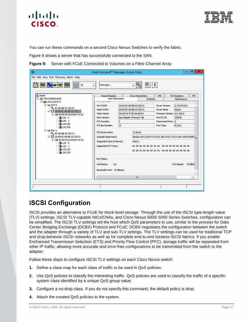
Figure 9 shows a server that has successfully connected to the SAN.
Figure 9: Server with FCoE Connected to Volumes on a Fibre Channel Array
iSCSI Configuration
iSCSI provides an alternative to FCoE for block-level storage. Through the use of the iSCSI type-length-value
(TLV) settings, iSCSI TLV-capable NICs/CNAs, and Cisco Nexus 5000/ 6000 Series Switches, configuration can
be simplified. The iSCSI TLV settings tell the host which QoS parameters to use, similar to the process for Data
Center Bridging Exchange (DCBX) Protocol and FCoE; DCBX negotiates the configuration between the switch
and the adapter through a variety of TLV and sub-TLV settings. The TLV settings can be used for traditional TCP
and drop-behavior iSCSI networks as well as for complete end-to-end lossless iSCSI fabrics. If you enable
Enchanced Transmisson Selection (ETS) and Priority Flow Control (PFC), storage traffic will be separated from
other IP traffic, allowing more accurate and error-free configurations to be transmitted from the switch to the
adapter.
Follow these steps to configure iSCSI TLV settings on each Cisco Nexus switch:
1. Define a class map for each class of traffic to be used in QoS policies.
2. Use QoS policies to classify the interesting traffic. QoS policies are used to classify the traffic of a specific
system class identified by a unique QoS group value.
3. Configure a no-drop class. If you do not specify this command, the default policy is drop.
4. Attach the created QoS policies to the system.

© 2014 Cisco | IBM. All rights reserved. Page 28
1. Define a class map of QoS policies on the first switch to identify the iSCSI traffic (here, iSCSI traffic is
matched to class-of-service [CoS] 5):
N5548-Bottom(config)# class-map type qos match-all iSCSI-C1
N5548-Bottom(config-cmap-qos)# match protocol iscsi
N5548-Bottom(config-cmap-qos)# match cos 5
2. Configure the type of QoS policies used to classify the traffic of a specific system class (here, the
QoS-group value 2 is used):
N5548-Bottom(config)# policy-map type qos iSCSI-C1
N5548-Bottom(config-pmap-qos) class iSCSI-C1
N5548-Bottom(config-pmap-c-qos)# set qos-group 2
N5548-Bottom(config-pmap-c-qos)# exit
N5548-Bottom(config-pmap-c-qos)# class class-default
3. Configure the no-drop policy maps:
N5548-Bottom(config)# class-map type network-qos iSCSI-C1
N5548-Bottom(config-cmap-nq)# match qos-group 2
N5548-Bottom(config-cmap-nq)# exit
N5548-Bottom(config)# policy-map type network-qos iSCSI-C1
N5548-Bottom(config-pmap-nq)# class type network-qos iSCSI-C1
N5548-Bottom(config-pmap-nq-c)# pause no-drop
N5548-Bottom(config-pmap-nq-c)# class type network-qos class-default
N5548-Bottom(config-pmap-nq-c)# mtu 9216
4. Apply the system service policies:
N5548-Bottom(config-sys-qos)# service-policy type qos input iSCSI-C1
N5548-Bottom(config-sys-qos)# service-policy type network-qos iSCSI-C1
5. Identify the iSCSI traffic on the other Cisco Nexus switch using the same process as for the first
switch by defining a class map for each class of traffic to be used in the QoS policies:
N5548-Top(config)# class-map type qos match-all iSCSI-C1
N5548-Top(config-cmap-qos)# match protocol iscsi
N5548-Top(config-cmap-qos)# match cos 5
6. Configure the QoS policy type:
N5548-Top(config)# policy-map type qos iSCSI-C1
N5548-Top(config-pmap-qos) class iSCSI-C1
N5548-Top(config-pmap-c-qos)# set qos-group 2
N5548-Top(config-pmap-c-qos)# exit
N5548-Top(config-pmap-c-qos)# class class-default

© 2014 Cisco | IBM. All rights reserved. Page 29
7. Configure the no-drop policy maps:
N5548-Top(config)# class-map type network-qos iSCSI-C1
N5548-Top(config-cmap-nq)# match qos-group 2
N5548-Top(config-cmap-nq)# exit
N5548-Top(config)# policy-map type network-qos iSCSI-C1
N5548-Top(config-pmap-nq)# class type network-qos iSCSI-C1
N5548-Top(config-pmap-nq-c)# pause no-drop
N5548-Top(config-pmap-nq-c)# class type network-qos class-default
N5548-Top(config-pmap-nq-c)# mtu 9216
8. Apply the system service policies:
N5548-Top(config-sys-qos)# service-policy type qos input iSCSI-C1
N5548-Top(config-sys-qos)# service-policy type network-qos iSCSI-C1
Figure 10 shows how the iSCSI ports appear in VMware ESXi. Two additional storage adapters are created in VMware ESXi.
Figure 10: IBM Flex System X440+10GB Fabric Blade Running VMware ESXi 5.1.0,1065491

© 2014 Cisco | IBM. All rights reserved. Page 30
The storage array should then be visible as shown in Figure 11.
Figure 11: IBM Flex System X440+10GB Fabric Blade Running VMware ESXi 5.1.0,1065491
Virtual Network Adapter Partitioning
Various IBM adapters can present a single Ethernet link to the server operating system as if it were different
physical adapters. This capability allows bare-metal servers and hypervisors to offer multiple NICs and adapters
while physically having a pair of high-bandwidth links. This feature provides the flexibility to limit the bandwidth
allocated to each virtual adapter without the need for a server administrator to know the network QoS
configuration parameters.
To configure the virtual adapter function, follow this procedure:
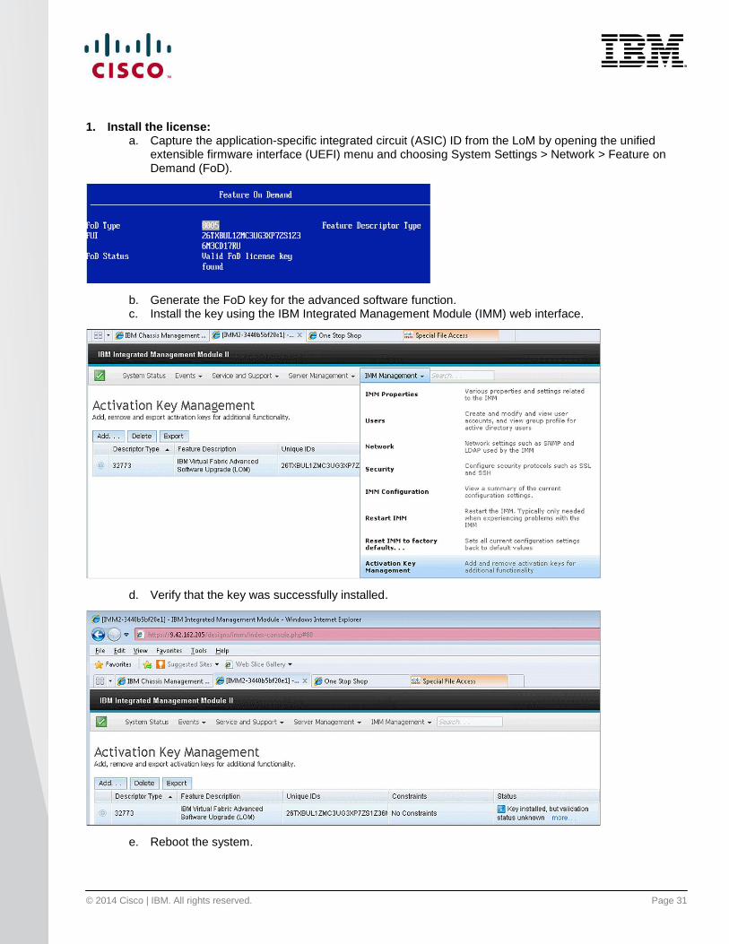
1. Install the license.
2. Configure the virtual network adapters.
3. Configure the switch interface for the correct VLANs.
© 2014 Cisco | IBM. All rights reserved. Page 31
1. Install the license: a. Capture the application-specific integrated circuit (ASIC) ID from the LoM by opening the unified
extensible firmware interface (UEFI) menu and choosing System Settings > Network > Feature on Demand (FoD).
b. Generate the FoD key for the advanced software function. c. Install the key using the IBM Integrated Management Module (IMM) web interface.
d. Verify that the key was successfully installed.
e. Reboot the system.
© 2014 Cisco | IBM. All rights reserved. Page 32
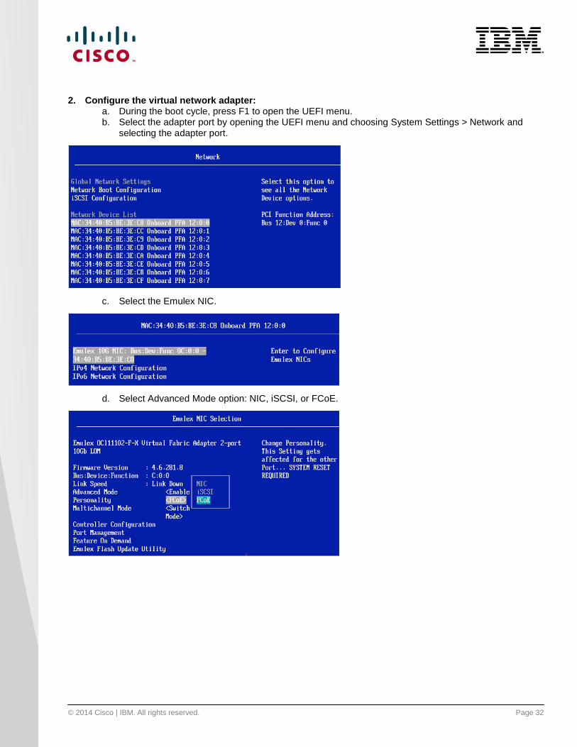
2. Configure the virtual network adapter: a. During the boot cycle, press F1 to open the UEFI menu. b. Select the adapter port by opening the UEFI menu and choosing System Settings > Network and
selecting the adapter port.
c. Select the Emulex NIC.
d. Select Advanced Mode option: NIC, iSCSI, or FCoE.

© 2014 Cisco | IBM. All rights reserved. Page 33
e. Make sure that the multichannel mode is set to Switch Independent and select Controller Configuration.
f. Select the Configure Bandwidth option.
g. Allocate the minimum and maximum bandwidth.
Note: Function 2 on both physical NICs corresponds to the second vNIC, which can be the iSCSI or FCoE initiator. In this
example, it is the FCoE initiator with 4-Gbps of bandwidth allocated.

© 2014 Cisco | IBM. All rights reserved. Page 34
h. Select the Configure LPVID option.
3. Configure unique VLANs as necessary for each Ethernet vNIC.
a. This feature works by applying VLAN tags to the traffic egressing the adapter and entering the network. Thus, for correct operation, the VLAN tags on the physical network port to the adapter must match. Note that a VLAN ID cannot be assigned for the FCoE vNIC.
b. Make sure that the VLANs are configured and allowed on the internal and external switch ports as needed.
c. Configure the network port attached to the server. Use the following configuration as a reference.
interface Ethernet191/1/7
switchport mode trunk
switchport trunk native vlan 182
switchport trunk allowed vlan 182,200
spanning-tree port type edge trunk
channel-group 207
interface port-channel207
switchport mode trunk
switchport trunk native vlan 182
switchport trunk allowed vlan 182,200
spanning-tree port type edge trunk

© 2014 Cisco | IBM. All rights reserved. Page 35
Debug Commands show fex
This command displays the status of the fabric extenders that are powered on and connected.
Cisco Nexus B22 for IBM installed but parent switch not configured:
N5548-Bottom# show fex
FEX FEX FEX FEX
Number Description State Model Serial
------------------------------------------------------------------------
--- -------- Discovered N2K-B22IBM-P FOC1515ZZU4
N5548-Bottom#
Cisco Nexus B22 for IBM loading after parent switch is configured:
N5548-Bottom(config-if)# show fex
FEX FEX FEX FEX
Number Description State Model Serial
------------------------------------------------------------------------
103 FEX0103 Connected N2K-B22IBM-P FOC1515ZZU4
N5548-Bottom(config-if)#
N5548-Bottom#
show fex
FEX FEX FEX FEX Fex
Number Description State Model Serial
------------------------------------------------------------------------
191 FEX0191 Online N2K-B22IBM-P FOC1730R0XQ
192 FEX0192 Online N2K-B22IBM-P FOC1730R0XM
Cisco Nexus B22 for IBM online and ready for use:
N5548-Top# show fex
FEX FEX FEX FEX
Number Description State Model Serial
------------------------------------------------------------------------
104 FEX0104 Online N2K-B22IBM-P FOC1515ZZUU
N5548-Top#
N5548-Top#
N5548-Top#
show fex
© 2014 Cisco | IBM. All rights reserved. Page 36
FEX FEX FEX FEX Fex
Number Description State Model Serial
191 FEX0191 Online N2K-B22IBM-P FOC1730R0XQ
192 FEX0192 Online N2K-B22IBM-P FOC1730R0XM
show fex detail
This command displays the details of the fabric extender module, including the connection blade bay number,
rack name, and enclosure information for the blade server chassis.
N5548-Top#
show fex 191 detail
FEX: 191 Description: FEX0191 state: Online
FEX version: 6.0(2)N2(1a) [Switch version: 6.0(2)N2(1a)]
FEX Interim version: 6.0(2)N2(1a.19)
Switch Interim version: 6.0(2)N2(1a.19)
Extender Serial: FOC1730R0XQ
Extender Model: N2K-B22IBM-P, Part No: 73-15000-03
Bay: 1
Machine Type/Model: 8721HC1
Machine Serial Number: 06MVGY8
UUID: 100E 4829 C606 45B1 A8E1 D697 BCCD 2884
Card Id: 211, Mac Addr: f8:4f:57:ce:36:42, Num Macs: 64
Module Sw Gen: 21 [Switch Sw Gen: 21]
post level: complete
Pinning-mode: static Max-links: 1
Fabric port for control traffic: Eth1/17
FCoE Admin: false
FCoE Oper: false
FCoE FEX AA Configured: true
Fabric interface state:
Po191 - Interface Up. State: Active
Eth1/17 - Interface Up. State: Active
Fex Port State Fabric Port
Eth191/1/1 Up Po191
Eth191/1/2 Down Po191
Eth191/1/3 Up Po191
Eth191/1/4 Up Po191
Eth191/1/5 Down Po191
Eth191/1/6 Down Po191
Eth191/1/7 Up Po191
Eth191/1/8 Down Po191
Eth191/1/9 Down Po191
Eth191/1/10 Down Po191
Eth191/1/11 Down Po191
Eth191/1/12 Down Po191
© 2014 Cisco | IBM. All rights reserved. Page 37
Eth191/1/13 Down Po191
Eth191/1/14 Up Po191
Logs:
09/25/2013 11:09:20.990637: Module register received
09/25/2013 11:09:20.993278: Registration response sent
09/25/2013 11:09:21.98103: create module inserted event.
09/25/2013 11:09:21.99012: Module Online Sequence
09/25/2013 11:09:22.829803: Module Online
show interface brief
This command displays a summary of the interfaces with information including the VLAN, link status, and speed.
N5548-Top# show interface brief
-------------------------------------------------------------------------------
Interface Vsan Admin Admin Status SFP Oper Oper Port
Mode Trunk Mode Speed Channel
Mode (Gbps)
-------------------------------------------------------------------------------
fc1/41 1 auto on sfpAbsent -- -- --
fc1/42 1 auto on sfpAbsent -- -- --
fc1/43 1 auto on sfpAbsent -- -- --
fc1/44 1 auto on sfpAbsent -- -- --
fc1/45 1 auto on sfpAbsent -- -- --
fc1/46 1 auto on sfpAbsent -- -- --
fc1/47 1 auto on down swl -- --
fc1/48 201 F on up swl F 8 --
--------------------------------------------------------------------------------
Ethernet VLAN Type Mode Status Reason Speed Port
Interface Ch #
--------------------------------------------------------------------------------
Eth1/1 1 eth fabric up none 10G(D) --
Eth1/2 1 eth fabric up none 10G(D) --
Eth1/3 1 eth access down SFP not inserted 10G(D) --
Eth1/4 1 eth access down SFP not inserted 10G(D) --
Eth1/5 1 eth fabric up none 10G(D) 61
Eth1/6 1 eth fabric up none 10G(D) 61
Eth1/7 182 eth access up none 1000(D) --
Eth1/8 182 eth access up none 1000(D) --
Eth1/9 1 eth trunk up none 10G(D) 20
Eth1/10 1 eth trunk down SFP not inserted 10G(D) 20
Eth1/11 1 eth access down SFP not inserted 10G(D) --

© 2014 Cisco | IBM. All rights reserved. Page 38
Eth1/12 1 eth access down SFP not inserted 10G(D) --
Eth1/13 1 eth access down SFP not inserted 10G(D) --
Eth1/14 1 eth access down SFP not inserted 10G(D) --
Eth1/15 1 eth access down SFP not inserted 10G(D) --
Eth1/16 1 eth access down SFP not inserted 10G(D) --
Eth1/17 1 eth fabric up none 10G(D) 191
Eth1/18 1 eth fabric up none 10G(D) 192
Eth1/19 1 eth fabric up none 10G(D) 193
Eth1/20 1 eth fabric up none 10G(D) 194
Eth1/21 1 eth access down SFP not inserted 10G(D) --
Eth1/22 1 eth access down SFP not inserted 10G(D) --
Eth1/23 1 eth access down SFP not inserted 10G(D) --
Eth1/24 1 eth access down SFP not inserted 10G(D) --
Eth1/25 1 eth access down SFP not inserted 10G(D) --
Eth1/26 1 eth access down SFP not inserted 10G(D) --
Eth1/27 1 eth access down SFP not inserted 10G(D) --
Eth1/28 1 eth access down SFP not inserted 10G(D) --
Eth1/29 1 eth access down SFP not inserted 10G(D) --
Eth1/30 1 eth access down SFP not inserted 10G(D) --
Eth1/31 1 eth access down SFP not inserted 10G(D) --
Eth1/32 1 eth access down SFP not inserted 10G(D) --
Eth1/33 1 eth access down SFP not inserted 10G(D) --
Eth1/34 1 eth access down SFP not inserted 10G(D) --
Eth1/35 1 eth access down SFP not inserted 10G(D) --
Eth1/36 1 eth access down SFP not inserted 10G(D) --
Eth1/37 1 eth access down SFP not inserted 10G(D) --
Eth1/38 1 eth access down SFP not inserted 10G(D) --
Eth1/39 1 eth access down SFP not inserted 10G(D) --
Eth1/40 1 eth access down SFP not inserted 10G(D) --
Eth2/1 1 eth access down SFP not inserted 10G(D) --
Eth2/2 1 eth access down SFP not inserted 10G(D) --
Eth2/3 1 eth access down SFP not inserted 10G(D) --
Eth2/4 1 eth access down SFP not inserted 10G(D) --
Eth2/5 1 eth access down SFP not inserted 10G(D) --
Eth2/6 1 eth access down SFP not inserted 10G(D) --
Eth2/7 1 eth access down SFP not inserted 10G(D) --
Eth2/8 1 eth access down SFP not inserted 10G(D) --
Eth2/9 1 eth access down SFP not inserted 10G(D) --
Eth2/10 1 eth access down SFP not inserted 10G(D) --
Eth2/11 1 eth access down SFP not inserted 10G(D) --
Eth2/12 1 eth access down SFP not inserted 10G(D) --
Eth2/13 1 eth access down SFP not inserted 10G(D) --
Eth2/14 1 eth access down SFP not inserted 10G(D) --
Eth2/15 1 eth access down SFP not inserted 10G(D) --
Eth2/16 1 eth access down SFP not inserted 10G(D) --
© 2014 Cisco | IBM. All rights reserved. Page 39
--------------------------------------------------------------------------------
Port-channel VLAN Type Mode Status Reason Speed Protocol
Interface
--------------------------------------------------------------------------------
Po10 1 eth trunk down No operational members auto(I) lacp
Po20 1 eth trunk up none a-10G(D) none
Po61 1 eth fabric up none a-10G(D) none
Po191 1 eth fabric up none a-10G(D) none
Po192 1 eth fabric up none a-10G(D) none
Po193 1 eth fabric up none a-10G(D) none
Po194 1 eth fabric up none a-10G(D) none
Po201 182 eth access up none a-10G(D) none
Po202 182 eth access up none a-10G(D) none
Po203 182 eth access up none a-10G(D) none
Po207 182 eth trunk up none a-10G(D) none
Po214 182 eth access up none a-10G(D) none
Po215 182 eth trunk up none a-10G(D) none
--------------------------------------------------------------------------------
Port VRF Status IP Address Speed MTU
--------------------------------------------------------------------------------
mgmt0 -- up 172.25.182.109 1000 1500
-------------------------------------------------------------------------------
Interface Vsan Admin Admin Status Bind Oper Oper
Mode Trunk Info Mode Speed
Mode (Gbps)
-------------------------------------------------------------------------------
vfc1032 201 F on trunking Eth192/1/7 TF auto
vfc1033 201 F on trunking Eth192/1/14 TF auto
-------------------------------------------------------------------------------
Interface Secondary VLAN(Type) Status Reason
-------------------------------------------------------------------------------
Vlan1 -- down Administratively down
Vlan50 -- up --
--------------------------------------------------------------------------------
Ethernet VLAN Type Mode Status Reason Speed Port
Interface Ch #
--------------------------------------------------------------------------------
Eth160/1/1 1 eth access up none 10G(D) --
Eth160/1/2 1 eth access down Link not connected auto(D) --
Eth160/1/3 1 eth access down Link not connected auto(D) --
Eth160/1/4 1 eth access down Link not connected auto(D) --
Eth160/1/5 1 eth access down Link not connected auto(D) --

© 2014 Cisco | IBM. All rights reserved. Page 40
Eth160/1/6 1 eth access down Link not connected auto(D) --
Eth160/1/7 1 eth access down Link not connected auto(D) --
Eth160/1/8 1 eth access down Link not connected auto(D) --
Eth160/1/9 1 eth access down Link not connected auto(D) --
Eth160/1/10 1 eth access down Link not connected auto(D) --
Eth160/1/11 1 eth access down Link not connected auto(D) --
Eth160/1/12 1 eth access down Link not connected auto(D) --
Eth160/1/13 1 eth access down Link not connected auto(D) --
Eth160/1/14 1 eth access down Link not connected auto(D) --
Eth160/1/15 1 eth access down Link not connected auto(D) --
Eth160/1/16 1 eth access down Link not connected auto(D) --
Eth161/1/1 1 eth access up none 10G(D) --
Eth161/1/2 1 eth access up none 1000(D) --
Eth161/1/3 1 eth access down Link not connected auto(D) --
Eth161/1/4 1 eth access down Link not connected auto(D) --
Eth161/1/5 1 eth access up none 1000(D) --
Eth161/1/6 1 eth access up none 10G(D) --
Eth161/1/7 1 eth access down Link not connected auto(D) --
Eth161/1/8 1 eth access down Link not connected auto(D) --
Eth161/1/9 1 eth access down Link not connected auto(D) --
Eth161/1/10 1 eth access down Link not connected auto(D) --
Eth161/1/11 1 eth access down Link not connected auto(D) --
Eth161/1/12 1 eth access down Link not connected auto(D) --
Eth161/1/13 1 eth access up none 1000(D) --
Eth161/1/14 1 eth access up none 10G(D) --
Eth161/1/15 1 eth access down Link not connected auto(D) --
Eth161/1/16 1 eth access down Link not connected auto(D) --
Eth191/1/1 182 eth access up none 10G(D) 201
Eth191/1/2 1 eth access down Link not connected auto(D) --
Eth191/1/3 182 eth access up none 10G(D) 203
Eth191/1/4 182 eth access up none 10G(D) 202
Eth191/1/5 1 eth access down Link not connected auto(D) --
Eth191/1/6 1 eth access down Link not connected auto(D) --
Eth191/1/7 182 eth trunk up none 10G(D) 207
Eth191/1/8 1 eth access down Link not connected auto(D) --
Eth191/1/9 1 eth access down Link not connected auto(D) --
Eth191/1/10 1 eth access down Link not connected auto(D) --
Eth191/1/11 1 eth access down Link not connected auto(D) --
Eth191/1/12 1 eth access down Link not connected auto(D) --
Eth191/1/13 1 eth access down Link not connected auto(D) --
Eth191/1/14 182 eth access up none 10G(D) 214
Eth192/1/1 182 eth access up none 10G(D) --
Eth192/1/2 1 eth access down Link not connected auto(D) --
Eth192/1/3 182 eth access up none 10G(D) 203
Eth192/1/4 182 eth access up none 10G(D) --
Eth192/1/5 1 eth access down Link not connected auto(D) --
© 2014 Cisco | IBM. All rights reserved. Page 41
Eth192/1/6 1 eth access down Link not connected auto(D) --
Eth192/1/7 182 eth trunk up none 10G(D) 207
Eth192/1/8 1 eth access down Link not connected auto(D) --
Eth192/1/9 1 eth access down Link not connected auto(D) --
Eth192/1/10 1 eth access down Link not connected auto(D) --
Eth192/1/11 1 eth access down Link not connected auto(D) --
Eth192/1/12 1 eth access down Link not connected auto(D) --
Eth192/1/13 1 eth access down Link not connected auto(D) --
Eth192/1/14 182 eth trunk up none 10G(D) 215
Eth193/1/1 1 eth access down Link not connected auto(D) --
Eth193/1/2 1 eth access up none 10G(D) --
Eth193/1/3 1 eth access down Link not connected auto(D) --
Eth193/1/4 1 eth access down Link not connected auto(D) --
Eth193/1/5 1 eth access down Link not connected auto(D) --
Eth193/1/6 1 eth access down Link not connected auto(D) --
Eth193/1/7 1 eth access down Link not connected auto(D) --
Eth193/1/8 1 eth access down Link not connected auto(D) --
Eth193/1/9 1 eth access down Link not connected auto(D) --
Eth193/1/10 1 eth access down Link not connected auto(D) --
Eth193/1/11 1 eth access down Link not connected auto(D) --
Eth193/1/12 1 eth access down Link not connected auto(D) --
Eth193/1/13 1 eth access down Link not connected auto(D) --
Eth193/1/14 1 eth access down Link not connected auto(D) --
Eth194/1/1 1 eth access down Link not connected auto(D) --
Eth194/1/2 1 eth access up none 10G(D) --
Eth194/1/3 1 eth access down Link not connected auto(D) --
Eth194/1/4 1 eth access down Link not connected auto(D) --
Eth194/1/5 1 eth access down Link not connected auto(D) --
Eth194/1/6 1 eth access down Link not connected auto(D) --
Eth194/1/7 1 eth access down Link not connected auto(D) --
Eth194/1/8 1 eth access down Link not connected auto(D) --
Eth194/1/9 1 eth access down Link not connected auto(D) --
Eth194/1/10 1 eth access down Link not connected auto(D) --
Eth194/1/11 1 eth access down Link not connected auto(D) --
Eth194/1/12 1 eth access down Link not connected auto(D) --
Eth194/1/13 1 eth access down Link not connected auto(D) --
Eth194/1/14 1 eth access down Link not connected auto(D) --

© 2014 Cisco | IBM. All rights reserved. Page 42
show interface ethernet 191/1/1
This command displays detailed statistics for Cisco Nexus B22 for IBM fabric extender port 1.
N5548-Bottom# show interface ethernet 191/1/1
Ethernet191/1/1 is up
Belongs to Po201
Hardware: 1000/10000 Ethernet, address: f84f.57ce.3642 (bia f84f.57ce.3642)
MTU 1500 bytes, BW 10000000 Kbit, DLY 10 usec
reliability 255/255, txload 1/255, rxload 1/255
Encapsulation ARPA
Port mode is access
full-duplex, 10 Gb/s
Beacon is turned off
Input flow-control is off, output flow-control is on
Switchport monitor is off
EtherType is 0x8100
Last link flapped 19:40:49
Last clearing of "show interface" counters never
12 interface resets
30 seconds input rate 40 bits/sec, 0 packets/sec
30 seconds output rate 2592 bits/sec, 4 packets/sec
Load-Interval #2: 5 minute (300 seconds)
input rate 152 bps, 0 pps; output rate 3.31 Kbps, 4 pps
RX
1414070 unicast packets 6375 multicast packets 11769 broadcast packets
1432214 input packets 108330909 bytes
0 jumbo packets 0 storm suppression bytes
0 runts 0 giants 0 CRC 0 no buffer
0 input error 0 short frame 0 overrun 0 underrun 0 ignored
0 watchdog 0 bad etype drop 0 bad proto drop 0 if down drop
0 input with dribble 0 input discard
0 Rx pause
TX
3062593 unicast packets 87916 multicast packets 318028 broadcast packets
3468537 output packets 4619474058 bytes
0 jumbo packets
0 output error 0 collision 0 deferred 0 late collision
0 lost carrier 0 no carrier 0 babble 0 output discard
0 Tx pause
© 2014 Cisco | IBM. All rights reserved. Page 43
show vlan
This command displays the VLAN and the ports associated with the VLAN.
N5548-Bottom(config-if)# show vlan
N5548-Bottom(config-if)#
N5548-Bottom# show vlan
VLAN Name Status Ports
---- -------------------------------- --------- -------------------------------
1 default active Po20, Eth1/2, Eth1/3, Eth1/4
Eth1/5, Eth1/6, Eth1/9, Eth1/10
Eth1/11, Eth1/12, Eth1/13
Eth1/14, Eth1/15, Eth1/16
Eth1/21, Eth1/22, Eth1/23
Eth1/24, Eth1/25, Eth1/26
Eth1/27, Eth1/28, Eth1/29
Eth1/30, Eth1/31, Eth1/32
Eth1/33, Eth1/34, Eth1/35
Eth1/36, Eth1/37, Eth1/38
Eth1/39, Eth1/40, Eth2/1, Eth2/2
Eth2/3, Eth2/4, Eth2/5, Eth2/6
Eth2/7, Eth2/8, Eth2/9, Eth2/10
Eth2/11, Eth2/12, Eth2/13
Eth2/14, Eth2/15, Eth2/16
Eth191/1/2, Eth191/1/5
Eth191/1/6, Eth191/1/8
Eth191/1/9, Eth191/1/10
Eth191/1/11, Eth191/1/12
Eth191/1/13, Eth192/1/2
Eth192/1/5, Eth192/1/6
Eth192/1/8, Eth192/1/9
Eth192/1/10, Eth192/1/11
Eth192/1/12, Eth192/1/13
Eth193/1/1, Eth193/1/2
Eth193/1/3, Eth193/1/4
Eth193/1/5, Eth193/1/6
Eth193/1/7, Eth193/1/8
Eth193/1/9, Eth193/1/10
Eth193/1/11, Eth193/1/12
Eth193/1/13, Eth193/1/14

© 2014 Cisco | IBM. All rights reserved. Page 44
Eth194/1/1, Eth194/1/2
Eth194/1/3, Eth194/1/4
Eth194/1/5, Eth194/1/6
Eth194/1/7, Eth194/1/8
Eth194/1/9, Eth194/1/10
Eth194/1/11, Eth194/1/12
Eth194/1/13, Eth194/1/14
50 iSCSI-VL50 active Po20, Eth1/9, Eth1/10
77 VLAN0077 active Po20, Eth1/9, Eth1/10
182 MGMT active Po20, Po201, Po202, Po203
Po207, Po214, Po215, Eth1/7
Eth1/8, Eth1/9, Eth1/10
Eth191/1/1, Eth191/1/3
Eth191/1/4, Eth191/1/7
Eth191/1/14, Eth192/1/1
Eth192/1/3, Eth192/1/4
Eth192/1/7, Eth192/1/14
200 FCoE-VL200 active Po20, Po207, Po215, Eth1/9
Eth1/10, Eth191/1/7, Eth192/1/7
Eth192/1/14
VLAN Type Vlan-mode
---- ----- ----------
1 enet CE
50 enet CE
77 enet CE
182 enet CE
200 enet CE
Primary Secondary Type Ports
------- --------- --------------- -------------------------------------------
show interface fex-fabric
This command displays a list of interfaces and their association with fabric extenders.
N5K_Bottom# show interface fex-fabric
N5548-Bottom# show interface fex-fabric
Fabric Fabric Fex FEX Fex
Fex Port Port State Uplink Model Serial
---------------------------------------------------------------
135 Eth1/1 Configured 0
191 Eth1/17 Active 1 N2K-B22IBM-P FOC1730R0XQ
192 Eth1/18 Active 1 N2K-B22IBM-P FOC1730R0XM
193 Eth1/19 Active 1 N2K-B22IBM-P FOC1730R0WU
© 2014 Cisco | IBM. All rights reserved. Page 45
194 Eth1/20 Active 1 N2K-B22IBM-P FOC1720R0VV
N5596-1-B22#
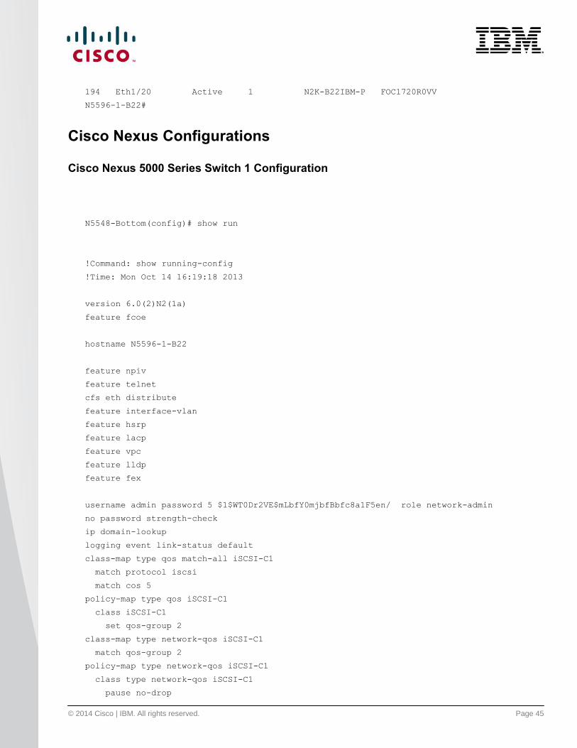
Cisco Nexus Configurations
Cisco Nexus 5000 Series Switch 1 Configuration
N5548-Bottom(config)# show run
!Command: show running-config
!Time: Mon Oct 14 16:19:18 2013
version 6.0(2)N2(1a)
feature fcoe
hostname N5596-1-B22
feature npiv
feature telnet
cfs eth distribute
feature interface-vlan
feature hsrp
feature lacp
feature vpc
feature lldp
feature fex
username admin password 5 $1$WT0Dr2VE$mLbfY0mjbfBbfc8a1F5en/ role network-admin
no password strength-check
ip domain-lookup
logging event link-status default
class-map type qos match-all iSCSI-C1
match protocol iscsi
match cos 5
policy-map type qos iSCSI-C1
class iSCSI-C1
set qos-group 2
class-map type network-qos iSCSI-C1
match qos-group 2
policy-map type network-qos iSCSI-C1
class type network-qos iSCSI-C1
pause no-drop

© 2014 Cisco | IBM. All rights reserved. Page 46
class type network-qos class-default
mtu 9216
multicast-optimize
system qos
service-policy type queuing input fcoe-default-in-policy
service-policy type queuing output fcoe-default-out-policy
service-policy type qos input iSCSI-C1
service-policy type network-qos iSCSI-C1
control-plane
service-policy input copp-system-policy-customized
fex 135
pinning max-links 1
description "FEX0135"
fex 191
pinning max-links 1
description "FEX0191"
fcoe
fex 192
pinning max-links 1
description "FEX0192"
fex 193
pinning max-links 1
description "FEX0193"
fcoe
fex 194
pinning max-links 1
description "FEX0194"
fcoe
slot 1
port 41-48 type fc
slot 2
port 1-16 type ethernet
snmp-server user admin network-admin auth md5 0x831c48b6e0670a2b350abe618a78f703 priv
0x831c48b6e
0670a2b350abe618a78f703 localizedkey
snmp-server community public group network-operator
ntp distribute
ntp server 161.44.248.75 use-vrf management
ntp commit
vrf context management
ip route 0.0.0.0/0 172.25.182.1
vlan 1,77
vlan 182
name MGMT
vlan 200

© 2014 Cisco | IBM. All rights reserved. Page 47
fcoe vsan 200
name FCoE-VL200
spanning-tree vlan 1-3967 priority 4096
vpc domain 5
role priority 1
system-priority 1
peer-keepalive destination 172.25.182.109 source 172.25.182.108
delay restore 150
port-profile default max-ports 512
vsan database
vsan 200 name "VS200"
fcdomain fcid database
vsan 1 wwn 50:00:40:20:05:df:43:2c fcid 0x190000 dynamic
vsan 200 wwn 50:00:40:20:05:df:43:2c fcid 0x300000 dynamic
vsan 200 wwn 10:00:6c:ae:8b:2c:cb:c1 fcid 0x300020 dynamic
vsan 200 wwn 10:00:6c:ae:8b:2c:d8:41 fcid 0x300040 dynamic
interface Vlan1
interface port-channel20
switchport mode trunk
spanning-tree port type network
vpc peer-link
interface port-channel191
switchport mode fex-fabric
fex associate 191
vpc 191
interface port-channel192
switchport mode fex-fabric
fex associate 192
vpc 192
interface port-channel193
switchport mode fex-fabric
fex associate 193
vpc 193
interface port-channel194
switchport mode fex-fabric
fex associate 194
vpc 194

© 2014 Cisco | IBM. All rights reserved. Page 48
interface port-channel201
switchport mode trunk
switchport trunk allowed vlan 182-184,200
interface port-channel202
switchport access vlan 182
interface port-channel203
switchport access vlan 182
interface port-channel207
switchport mode trunk
switchport trunk native vlan 182
switchport trunk allowed vlan 182,200
spanning-tree port type edge trunk
interface port-channel214
switchport mode trunk
switchport trunk native vlan 182
switchport trunk allowed vlan 182,200
spanning-tree port type edge trunk
interface port-channel215
switchport mode trunk
switchport trunk native vlan 182
switchport trunk allowed vlan 182,200
spanning-tree port type edge trunk
interface vfc1031
bind interface Ethernet191/1/1
switchport trunk allowed vsan 200
no shutdown
interface vfc1037
bind interface Ethernet191/1/7
switchport trunk allowed vsan 200
no shutdown
interface vfc1044
bind interface Ethernet191/1/14
switchport trunk allowed vsan 200
no shutdown
interface vfc1044
vsan database
vsan 200 interface vfc1031

© 2014 Cisco | IBM. All rights reserved. Page 49
vsan 200 interface vfc1037
vsan 200 interface vfc1044
vsan 200 interface fc1/48
interface fc1/41
interface fc1/42
interface fc1/43
interface fc1/44
interface fc1/45
interface fc1/46
interface fc1/47
interface fc1/48
no shutdown
interface Ethernet1/1
switchport mode fex-fabric
fex associate 135
spanning-tree port type edge
interface Ethernet1/2
interface Ethernet1/3
interface Ethernet1/4
interface Ethernet1/5
interface Ethernet1/6
interface Ethernet1/7
description iscsi-net0-nexsan
switchport access vlan 182
speed 1000
interface Ethernet1/8
switchport access vlan 182
speed 1000
interface Ethernet1/9

© 2014 Cisco | IBM. All rights reserved. Page 50
switchport mode trunk
channel-group 20
interface Ethernet1/10
switchport mode trunk
channel-group 20
interface Ethernet1/11
interface Ethernet1/12
interface Ethernet1/13
interface Ethernet1/14
interface Ethernet1/15
interface Ethernet1/16
interface Ethernet1/17
interface Ethernet1/18
interface Ethernet1/19
switchport mode fex-fabric
fex associate 193
channel-group 193
interface Ethernet1/20
switchport mode fex-fabric
fex associate 194
channel-group 194
interface Ethernet1/21
switchport mode fex-fabric
fex associate 191
channel-group 191
interface Ethernet1/22
switchport mode fex-fabric
fex associate 191
channel-group 191
interface Ethernet1/23
switchport mode fex-fabric
fex associate 192

© 2014 Cisco | IBM. All rights reserved. Page 51
channel-group 192
interface Ethernet1/24
switchport mode fex-fabric
fex associate 192
channel-group 192
interface Ethernet1/25
interface Ethernet1/26
interface Ethernet1/27
interface Ethernet1/28
interface Ethernet1/29
interface Ethernet1/30
interface Ethernet1/31
interface Ethernet1/32
interface Ethernet1/33
interface Ethernet1/34
interface Ethernet1/35
interface Ethernet1/36
interface Ethernet1/37
interface Ethernet1/38
interface Ethernet1/39
interface Ethernet1/40
interface Ethernet2/1
interface Ethernet2/2
interface Ethernet2/3
© 2014 Cisco | IBM. All rights reserved. Page 52
interface Ethernet2/4
interface Ethernet2/5
interface Ethernet2/6
interface Ethernet2/7
interface Ethernet2/8
interface Ethernet2/9
interface Ethernet2/10
interface Ethernet2/11
interface Ethernet2/12
interface Ethernet2/13
interface Ethernet2/14
interface Ethernet2/15
interface Ethernet2/16
interface mgmt0
ip address 172.25.182.108/24
interface Ethernet191/1/1
switchport mode trunk
switchport trunk allowed vlan 182,200
interface Ethernet191/1/2
interface Ethernet191/1/3
switchport access vlan 182
channel-group 203
interface Ethernet191/1/4
switchport access vlan 182
channel-group 202
interface Ethernet191/1/5

© 2014 Cisco | IBM. All rights reserved. Page 53
interface Ethernet191/1/6
interface Ethernet191/1/7
switchport mode trunk
switchport trunk native vlan 182
switchport trunk allowed vlan 182-184,200
channel-group 201 mode active
interface Ethernet191/1/8
interface Ethernet191/1/9
interface Ethernet191/1/10
interface Ethernet191/1/11
interface Ethernet191/1/12
interface Ethernet191/1/13
interface Ethernet191/1/14
switchport mode trunk
switchport trunk native vlan 182
switchport trunk allowed vlan 182,200
channel-group 214
interface Ethernet192/1/1
switchport mode trunk
switchport trunk allowed vlan 182,200
interface Ethernet192/1/2
interface Ethernet192/1/3
switchport access vlan 182
channel-group 203
interface Ethernet192/1/4
switchport access vlan 182
interface Ethernet192/1/5
interface Ethernet192/1/6
interface Ethernet192/1/7
switchport mode trunk
switchport trunk native vlan 182

© 2014 Cisco | IBM. All rights reserved. Page 54
switchport trunk allowed vlan 182-184,200
channel-group 201 mode active
interface Ethernet192/1/8
interface Ethernet192/1/9
interface Ethernet192/1/10
interface Ethernet192/1/11
interface Ethernet192/1/12
interface Ethernet192/1/13
interface Ethernet192/1/14
switchport mode trunk
switchport trunk native vlan 182
switchport trunk allowed vlan 182,200
interface Ethernet193/1/1
switchport mode trunk
spanning-tree port type edge trunk
channel-group 311
interface Ethernet193/1/2
interface Ethernet193/1/3
interface Ethernet193/1/4
interface Ethernet193/1/5
interface Ethernet193/1/6
interface Ethernet193/1/7
switchport mode trunk
spanning-tree port type edge trunk
channel-group 317
interface Ethernet193/1/8
interface Ethernet193/1/9
interface Ethernet193/1/10
© 2014 Cisco | IBM. All rights reserved. Page 55
interface Ethernet193/1/11
interface Ethernet193/1/12
interface Ethernet193/1/13
interface Ethernet193/1/14
clock timezone pst -7 0
system default zone default-zone permit
system default zone distribute full
cli alias name wr copy run start
line console
line vty
exec-timeout 1440
boot kickstart bootflash:/n5000-uk9-kickstart.6.0.2.N2.1a.19.bin
boot system bootflash:/n5000-uk9.6.0.2.N2.1a.19.bin
interface fc1/41
interface fc1/42
interface fc1/43
interface fc1/44
interface fc1/45
interface fc1/46
interface fc1/47
interface fc1/48
switchport mode F
zone default-zone permit vsan 200
zoneset distribute full vsan 200
!Full Zone Database Section for vsan 200
zone name zone1 vsan 200
member pwwn 50:00:40:20:05:df:43:2c
member pwwn 10:00:6c:ae:8b:2c:cb:c1
zone name zone2 vsan 200
member pwwn 50:00:40:20:05:df:43:2c
member pwwn 10:00:6c:ae:8b:2c:d8:41
zoneset name zoneset1 vsan 200
member zone1
member zone2
zoneset activate name zoneset1 vsan 200

© 2014 Cisco | IBM. All rights reserved. Page 56
Cisco Nexus 5000 Series Switch 2 Configuration
N5548-Top(config)# show run
!Command: show running-config
!Time: Mon Oct 14 16:21:29 2013
version 6.0(2)N2(1a)
feature fcoe
hostname N5596-2-B22
feature telnet
cfs eth distribute
feature ospf
feature interface-vlan
feature hsrp
feature lacp
feature vpc
feature lldp
feature fex
username admin password 5 $1$p4Mv/hIx$qEBLcupJS.7vx1a16TB6w1 role network-admin
no password strength-check
ip domain-lookup
logging event link-status default
class-map type qos match-all iSCSI-C1
match protocol iscsi
match cos 5
policy-map type qos iSCSI-C1
class iSCSI-C1
set qos-group 2
class-map type network-qos iSCSI-C1
match qos-group 2
policy-map type network-qos iSCSI-C1
class type network-qos iSCSI-C1
pause no-drop
class type network-qos class-default
mtu 9216
multicast-optimize
system qos
service-policy type queuing input fcoe-default-in-policy

© 2014 Cisco | IBM. All rights reserved. Page 57
service-policy type queuing output fcoe-default-out-policy
service-policy type qos input iSCSI-C1
service-policy type network-qos iSCSI-C1
control-plane
service-policy input copp-system-policy-customized
fex 160
pinning max-links 2
description "FEX0160"
fex 161
pinning max-links 1
description "FEX0161"
fex 191
pinning max-links 1
description "FEX0191"
fex 192
pinning max-links 1
description "FEX0192"
fcoe
fex 193
pinning max-links 1
description "FEX0193"
fcoe
fex 194
pinning max-links 1
description "FEX0194"
fcoe
fex 196
pinning max-links 1
description "FEX0196"
slot 1
port 41-48 type fc
slot 2
port 1-16 type ethernet
snmp-server user admin network-admin auth md5 0xa497c8207ab2dccb7b56b764f6d34be5 priv
0xa497c8207
ab2dccb7b56b764f6d34be5 localizedkey
snmp-server community public group network-operator
ntp distribute
ntp server 161.44.248.75 use-vrf management
ntp commit
vrf context management
ip route 0.0.0.0/0 172.25.182.1
vlan 1,77
vlan 182
name MGMT
© 2014 Cisco | IBM. All rights reserved. Page 58
vlan 201
fcoe vsan 201
name FCoE-VL201
spanning-tree vlan 1-3967 priority 8192
vpc domain 5
role priority 2
system-priority 1
peer-keepalive destination 172.25.182.108 source 172.25.182.109
delay restore 150
port-profile default max-ports 512
vsan database
vsan 201 name "VS201"
fcdomain fcid database
vsan 201 wwn 50:00:40:20:05:df:43:2c fcid 0x330000 dynamic
vsan 201 wwn 10:00:6c:ae:8b:2c:cb:c5 fcid 0x330020 dynamic
vsan 201 wwn 50:00:40:21:05:df:43:2c fcid 0x330001 dynamic
vsan 201 wwn 10:00:6c:ae:8b:2c:d8:45 fcid 0x330040 dynamic
interface Vlan1
interface port-channel10
switchport mode trunk
spanning-tree port type network
interface port-channel20
switchport mode trunk
spanning-tree port type network
speed 10000
vpc peer-link
interface port-channel61
switchport mode fex-fabric
fex associate 161
interface port-channel191
switchport mode fex-fabric
fex associate 191
vpc 191
interface port-channel192
switchport mode fex-fabric
fex associate 192
vpc 192

© 2014 Cisco | IBM. All rights reserved. Page 59
interface port-channel193
switchport mode fex-fabric
fex associate 193
vpc 193
interface port-channel194
switchport mode fex-fabric
fex associate 194
vpc 194
interface port-channel201
switchport mode trunk
switchport trunk allowed vlan 182-184,201
interface port-channel202
switchport access vlan 182
interface port-channel203
switchport access vlan 182
interface port-channel207
switchport mode trunk
switchport trunk native vlan 182
switchport trunk allowed vlan 182,201
spanning-tree port type edge trunk
interface port-channel214
switchport mode trunk
switchport trunk native vlan 182
switchport trunk allowed vlan 182,201
spanning-tree port type edge trunk
interface port-channel215
switchport mode trunk
switchport trunk native vlan 182
switchport trunk allowed vlan 182,201
spanning-tree port type edge trunk
interface port-channel311
switchport mode trunk
interface port-channel317
switchport mode trunk
inteface vfc1031
bind interface ethernet 192/1/1
© 2014 Cisco | IBM. All rights reserved. Page 60
switchport allowed vsan 201
no shutdown
interface vfc1037
bind interface Ethernet192/1/7
switchport trunk allowed vsan 201
no shutdown
interface vfc1044
bind interface Ethernet192/1/14
switchport trunk allowed vsan 201
no shutdown
vsan database
vsan 201 interface vfc1031
vsan 201 interface vfc1037
vsan 201 interface vfc1044
vsan 201 interface fc1/48
interface fc1/41
interface fc1/42
interface fc1/43
interface fc1/44
interface fc1/45
interface fc1/46
interface fc1/47
interface fc1/48
no shutdown
interface Ethernet1/1
switchport mode fex-fabric
fex associate 160
interface Ethernet1/2
switchport mode fex-fabric
fex associate 160
interface Ethernet1/3

© 2014 Cisco | IBM. All rights reserved. Page 61
interface Ethernet1/4
interface Ethernet1/5
switchport mode fex-fabric
fex associate 161
channel-group 61
interface Ethernet1/6
switchport mode fex-fabric
fex associate 161
channel-group 61
interface Ethernet1/7
description iscsi-net1-nexsan
switchport access vlan 182
speed 1000
interface Ethernet1/8
switchport access vlan 182
speed 1000
interface Ethernet1/9
switchport mode trunk
channel-group 20
interface Ethernet1/10
switchport mode trunk
channel-group 20
interface Ethernet1/11
interface Ethernet1/12
interface Ethernet1/13
interface Ethernet1/14
interface Ethernet1/15
interface Ethernet1/16
interface Ethernet1/17
interface Ethernet1/18

© 2014 Cisco | IBM. All rights reserved. Page 62
interface Ethernet1/19
switchport mode fex-fabric
fex associate 193
channel-group 193
interface Ethernet1/20
switchport mode fex-fabric
fex associate 194
channel-group 194
interface Ethernet1/21
switchport mode fex-fabric
fex associate 191
channel-group 191
interface Ethernet1/22
switchport mode fex-fabric
fex associate 191
channel-group 191
interface Ethernet1/23
switchport mode fex-fabric
fex associate 192
channel-group 192
interface Ethernet1/24
switchport mode fex-fabric
fex associate 192
channel-group 192
interface Ethernet1/25
switchport mode fex-fabric
fex associate 196
interface Ethernet1/26
switchport mode fex-fabric
fex associate 196
interface Ethernet1/27
switchport mode fex-fabric
fex associate 196

© 2014 Cisco | IBM. All rights reserved. Page 63
interface Ethernet1/28
switchport mode fex-fabric
fex associate 196
interface Ethernet1/29
switchport mode fex-fabric
fex associate 196
interface Ethernet1/30
switchport mode fex-fabric
fex associate 196
interface Ethernet1/31
switchport mode fex-fabric
fex associate 196
interface Ethernet1/32
switchport mode fex-fabric
fex associate 196
interface Ethernet1/33
interface Ethernet1/34
interface Ethernet1/35
interface Ethernet1/36
interface Ethernet1/37
interface Ethernet1/38
interface Ethernet1/39
interface Ethernet1/40
interface Ethernet2/1
interface Ethernet2/2
interface Ethernet2/3
interface Ethernet2/4
interface Ethernet2/5

© 2014 Cisco | IBM. All rights reserved. Page 64
interface Ethernet2/6
interface Ethernet2/7
interface Ethernet2/8
interface Ethernet2/9
interface Ethernet2/10
interface Ethernet2/11
interface Ethernet2/12
interface Ethernet2/13
interface Ethernet2/14
interface Ethernet2/15
interface Ethernet2/16
interface mgmt0
ip address 172.25.182.109/24
interface Ethernet160/1/1
interface Ethernet160/1/2
interface Ethernet160/1/3
interface Ethernet160/1/4
interface Ethernet160/1/5
interface Ethernet160/1/6
interface Ethernet160/1/7
interface Ethernet160/1/8
interface Ethernet160/1/9
interface Ethernet160/1/10

© 2014 Cisco | IBM. All rights reserved. Page 65
interface Ethernet160/1/11
interface Ethernet160/1/12
interface Ethernet160/1/13
interface Ethernet160/1/14
interface Ethernet160/1/15
interface Ethernet160/1/16
interface Ethernet161/1/1
interface Ethernet161/1/2
interface Ethernet161/1/3
interface Ethernet161/1/4
interface Ethernet161/1/5
interface Ethernet161/1/6
interface Ethernet161/1/7
interface Ethernet161/1/8
interface Ethernet161/1/9
interface Ethernet161/1/10
interface Ethernet161/1/11
interface Ethernet161/1/12
interface Ethernet161/1/13
interface Ethernet161/1/14
interface Ethernet161/1/15
interface Ethernet161/1/16
interface Ethernet191/1/1
switchport access vlan 182

© 2014 Cisco | IBM. All rights reserved. Page 66
switchport trunk allowed vlan 182-184,201
interface Ethernet191/1/2
interface Ethernet191/1/3
switchport access vlan 182
channel-group 203
interface Ethernet191/1/4
switchport access vlan 182
channel-group 202
interface Ethernet191/1/5
interface Ethernet191/1/6
interface Ethernet191/1/7
switchport mode trunk
switchport trunk native vlan 182
switchport trunk allowed vlan 182-184,201
channel-group 201 mode active
interface Ethernet191/1/8
interface Ethernet191/1/9
interface Ethernet191/1/10
interface Ethernet191/1/11
interface Ethernet191/1/12
interface Ethernet191/1/13
interface Ethernet191/1/14
switchport mode trunk
switchport trunk native vlan 182
switchport trunk allowed vlan 182,201
channel-group 214
interface Ethernet192/1/1
switchport mode trunk
switchport trunk allowed vlan 182,201
interface Ethernet192/1/2
© 2014 Cisco | IBM. All rights reserved. Page 67
interface Ethernet192/1/3
switchport access vlan 182
channel-group 203
interface Ethernet192/1/4
switchport access vlan 182
interface Ethernet192/1/5
interface Ethernet192/1/6
interface Ethernet192/1/7
switchport mode trunk
switchport trunk native vlan 182
switchport trunk allowed vlan 182-184,201
channel-group 201 mode active
interface Ethernet192/1/8
interface Ethernet192/1/9
interface Ethernet192/1/10
interface Ethernet192/1/11
interface Ethernet192/1/12
interface Ethernet192/1/13
interface Ethernet192/1/14
switchport mode trunk
switchport trunk native vlan 182
switchport trunk allowed vlan 182,201
interface Ethernet193/1/1
switchport mode trunk
spanning-tree port type edge trunk
channel-group 311
interface Ethernet193/1/2
interface Ethernet193/1/3
interface Ethernet193/1/4
interface Ethernet193/1/5
© 2014 Cisco | IBM. All rights reserved. Page 68
interface Ethernet193/1/6
interface Ethernet193/1/7
switchport mode trunk
spanning-tree port type edge trunk
channel-group 317
interface Ethernet193/1/8
interface Ethernet193/1/9
interface Ethernet193/1/10
interface Ethernet193/1/11
interface Ethernet193/1/12
interface Ethernet193/1/13
interface Ethernet193/1/14
interface Ethernet196/1/1
interface Ethernet196/1/2
interface Ethernet196/1/3
interface Ethernet196/1/4
interface Ethernet196/1/5
interface Ethernet196/1/6
interface Ethernet196/1/7
interface Ethernet196/1/8
interface Ethernet196/1/9
interface Ethernet196/1/10
interface Ethernet196/1/11
interface Ethernet196/1/12

© 2014 Cisco | IBM. All rights reserved. Page 69
interface Ethernet196/1/13
interface Ethernet196/1/14
clock timezone pst -7 0
system default zone default-zone permit
system default zone distribute full
cli alias name wr copy run start
line console
line vty
exec-timeout 1440
boot kickstart bootflash:/n5000-uk9-kickstart.6.0.2.N2.1a.19.bin
boot system bootflash:/n5000-uk9.6.0.2.N2.1a.19.bin
interface fc1/41
interface fc1/42
interface fc1/43
interface fc1/44
interface fc1/45
interface fc1/46
interface fc1/47
interface fc1/48
switchport mode F
zone default-zone permit vsan 201
zoneset distribute full vsan 201
!Full Zone Database Section for vsan 201
zone name zone1 vsan 201
member pwwn 50:00:40:21:05:df:43:2c
member pwwn 10:00:6c:ae:8b:2c:cb:c5
zone name zone2 vsan 201
member pwwn 50:00:40:21:05:df:43:2c
member pwwn 10:00:6c:ae:8b:2c:d8:45
zoneset name zoneset1 vsan 201
member zone1
member zone2
zoneset activate name zoneset1 vsan 201
© 2014 Cisco | IBM. All rights reserved. Page 70
© 2014 Cisco and/or its affiliates. All rights reserved. Cisco and the Cisco logo are trademarks or registered
trademarks of Cisco and/or its affiliates in the U.S. and other countries. To view a list of Cisco trademarks, go to
this URL: www.cisco.com/go/trademarks. Third-party trademarks mentioned are the property of their respective
owners. The use of the word partner does not imply a partnership relationship between Cisco and any other
company. (1110R)
IBM, IBM Flex System, and PureFlex are trademarks of International Business Machines Corp., registered in
many jurisdictions worldwide. Other product and service names might be trademarks of IBM or other
companies.
A current list of IBM trademarks is available on the web at http://www.ibm.com/legal/us/en/copytrade.shtml.
C07-730422-00 02/14
Conclusion
The advent of Cisco Nexus 2000 Series Fabric Extenders has enabled customers to benefit from both top-of-rack
(ToR) and end-of-row (EoR) designs. This technology achieves these benefits while reducing the costs
associated with cabling and cooling in EoR models and without introducing any additional management points, in
contrast to traditional ToR designs. This unique architecture has been tremendously successful in the first
generation of Cisco Nexus fabric extenders and rack-mount servers.
The Cisco Nexus B22 for IBM Blade Fabric Extender brings these innovations to third-party blade server chassis
and offers unified fabric with FCoE deployments for blade server chassis. This solution brings Cisco networking
innovations to the server access layer from rack-mount servers using Cisco Nexus 2000 Series Fabric Extenders
into third-party blade chassis.
For More Information
Cisco NX-OS operations guide for Cisco Nexus 5000 Series Switches:
http://www.cisco.com/en/US/docs/switches/datacenter/nexus5000/sw/operations/n5k_ops_guide.html
Fabric extender configuration (Cisco NX-OS 6.x):
http://www.cisco.com/en/US/docs/switches/datacenter/nexus6000/sw/layer2/6x/b_6k_Layer2_Config_6x.
html
SAN Switching Configuration Guide (Cisco NX-OS 6.x):
http://www.cisco.com/en/US/docs/switches/datacenter/nexus6000/sw/san_switching/6x/b_6k_SAN_Switc
hing_Config_6x.html
Nexus B22 Blade Fabric Extender Datasheet:
http://www.cisco.com/en/US/products/ps11975/index.html