Cisco LISP Host Mobility Data Center Interconnect (DCI) · Establishing L3 Peering between LISP DC...
86
Cisco LISP Host Mobility Data Center Interconnect (DCI) October 31, 2012
Transcript of Cisco LISP Host Mobility Data Center Interconnect (DCI) · Establishing L3 Peering between LISP DC...
Cisco LISP Host MobilityData Center Interconnect (DCI)October 31, 2012

Cisco LISP Host Mobility2
ALL DESIGNS, SPECIFICATIONS, STATEMENTS, INFORMATION, AND RECOMMENDATIONS (COLLECTIVELY, "DESIGNS") IN THIS MANUAL ARE PRESENTED "AS IS," WITH ALL FAULTS. CISCO AND ITS SUPPLIERS DIS-CLAIM ALL WARRANTIES, INCLUDING, WITHOUT LIMITATION, THE WARRANTY OF MERCHANTABILITY, FIT-NESS FOR A PARTICULAR PURPOSE AND NONINFRINGEMENT OR ARISING FROM A COURSE OF DEALING, USAGE, OR TRADE PRACTICE. IN NO EVENT SHALL CISCO OR ITS SUPPLIERS BE LIABLE FOR ANY INDIRECT, SPECIAL, CONSEQUENTIAL, OR INCIDENTAL DAMAGES, INCLUDING, WITHOUT LIMITATION, LOST PROFITS OR LOSS OR DAMAGE TO DATA ARISING OUT OF THE USE OR INABILITY TO USE THE DESIGNS, EVEN IF CISCO OR ITS SUPPLIERS HAVE BEEN ADVISED OF THE POSSIBILITY OF SUCH DAMAGES.
THE DESIGNS ARE SUBJECT TO CHANGE WITHOUT NOTICE. USERS ARE SOLELY RESPONSIBLE FOR THEIR APPLICATION OF THE DESIGNS. THE DESIGNS DO NOT CONSTITUTE THE TECHNICAL OR OTHER PROFES-SIONAL ADVICE OF CISCO, ITS SUPPLIERS OR PARTNERS. USERS SHOULD CONSULT THEIR OWN TECHNICAL ADVISORS BEFORE IMPLEMENTING THE DESIGNS. RESULTS MAY VARY DEPENDING ON FACTORS NOT TESTED BY CISCO.
The Cisco implementation of TCP header compression is an adaptation of a program developed by the University of California, Berkeley (UCB) as part of UCB’s public domain version of the UNIX operating system. All rights reserved. Copyright © 1981, Regents of the University of California.
Cisco and the Cisco Logo are trademarks of Cisco Systems, Inc. and/or its affiliates in the U.S. and other countries. A listing of Cisco's trademarks can be found at http://www.cisco.com/go/trademarks. Third party trademarks mentioned are the property of their respective owners. The use of the word partner does not imply a partnership relationship between Cisco and any other com-pany. (1005R)
Any Internet Protocol (IP) addresses and phone numbers used in this document are not intended to be actual addresses and phone numbers. Any examples, command display output, network topology diagrams, and other figures included in the document are shown for illustrative purposes only. Any use of actual IP addresses or phone numbers in illustrative content is unintentional and coincidental.
Cisco LISP Host Mobility
© 2012 Cisco Systems, Inc. All rights reserved.

Data Center Interconnect (DCI)
C O N T E N T S
Audience iv
Organization iv
Obtaining Documentation, Support, and Security Guidelines iv
CHAPTER 1 IP Mobility Overview 1-1
IP Mobility Requirements 1-1
Existing IP Mobility Solutions 1-2
Route Health Injection (RHI) and Host Routing 1-2
Mobile IPv4 1-2
Mobile IPv6 1-3
DNS Based Redirection: Global Site Selector (GSS) 1-3
CHAPTER 2 LISP Functional Overview 2-1
LISP Terminology 2-1
LISP Functionality 2-2
LISP Data Plane 2-2
LISP Control Plane 2-4
CHAPTER 3 LISP Host Mobility Solution 3-1
LISP Host Mobility Use Cases 3-2
LISP Host Mobility Hardware and Software Prerequisites 3-4
LISP Host Mobility Operation 3-5
Map-Server and Map-Resolver Deployment Considerations 3-6
Dynamic-EID Detection 3-7
CHAPTER 4 Deploying LISP Host Mobility with an Extended Subnet 4-1
LISP Host Mobility with an Extended Subnet Prerequisites 4-2
LISP Host Mobility with an Extended Subnet: Sample Config 4-2
Nexus 7000 N7K1A and N7K1B West DC-xTRs Configuration 4-2
Nexus 7000 N7K2A and N7K2B East DC-xTRs Configuration 4-5
Remote Site Cisco IOS-xTR Configuration 4-6
NX-OS Map-Server and Map-Resolver Configuration 4-7
iCisco LISP Host Mobility

Contents
Remote Clients Communicating to EIDs before a Mobility Event 4-10
Remote Clients Communicating to EIDs after a Mobility Event 4-17
East-West Traffic Flows Considerations 4-19
Intra-Subnet Traffic Flows 4-20
Inter-Subnets Traffic Flows 4-20
Summary 4-23
CHAPTER 5 Deploying LISP Host Mobility Across Subnets 5-1
LISP Host Mobility Across Subnets: Sample Config 5-2
Nexus 7000 N7K1A and N7K1B West DC-xTRs Configuration 5-2
Nexus 7000 N7K2A and N7K2B East DC-xTRs Configuration 5-4
Remote Site Cisco IOS-xTR Configuration 5-6
NX-OS Map-Server and Map-Resolver Configuration 5-7
Remote Clients Communicating to EIDs before a Mobility Event 5-10
Remote Clients Communicating to EIDs after a Mobility Event 5-12
East-West Traffic Flows Considerations 5-17
Intra-Subnet Traffic Flows 5-17
Inter-Subnets Traffic Flows 5-18
Summary 5-20
APPENDIX A LISP Host Mobility Deployment Best Practices A-1
LISP and MTU Considerations A-1
LISP Host Mobility with Extended Subnet and PIM Interaction A-1
Establishing L3 Peering between LISP DC xTR Devices A-4
Dealing with an ETR Failure Scenario A-5
Handling vPC Peer-Link Failure A-10
LISP and Services (FW, SLB) Integration Considerations A-11
FW and LISP xTR Positioning A-11
SLB and LISP xTR Positioning A-16
iiCisco LISP Host Mobility
Preface
The Locator Identity Separation Protocol (LISP) is a new routing architecture that creates a new paradigm by splitting the device identity, known as an Endpoint Identifier (EID), and its location, known as its Routing Locator (RLOC), into two different numbering spaces. This capability brings renewed scale and flexibility to the network in a single protocol, enabling the areas of mobility, scalability and security.
For enterprises, LISP provides several key benefits, including simplified enterprise multi-homing with ingress Traffic Engineering (TE) capabilities, high-scale multi-tenant VPN over Internet, simplified IPv6 transition support, and IP Mobility for Geographic Dispersion of Data Centers and Disaster Recovery.
This document focuses on the LISP Host Mobility use case addressing today's enterprise data center challenges. Server virtualization and high availability across geographically dispersed data centers are common in data center deployments today. Workload virtualization requires location independence for server resources, and requires the flexibility to move these server resources from one data center to another to meet increasing workloads and to support disaster recovery. This brings the challenge of route optimization, aiming at optimally routing traffic to the workload once it is migrated to the new location. It also mandates to keep the server's identity (IP address) the same across moves, so the clients can continue to send traffic regardless of the server's current location. At the same time, server migration or tighter requirements associated with disaster recovery procedures also introduce the need to provide IP mobility and dynamic traffic flows redirection across disperse data center sites.
The LISP Host Mobility solution addresses this issue seamlessly by enabling IP end-points to change location while keeping their assigned IP addresses. The workloads may move between different subnets or across different locations of a subnet that has been extended with Overlay Transport Virtualization (OTV) or another LAN extension mechanism. In either case, the LISP Host Mobility solution guarantees optimal routing between clients and the IP end-point that moved, regardless of its location. In addition, this solution does not require any change in the DNS infrastructure (since the mobile nodes preserve their original IP addressing), which overall reduces operating expenses for the data center administrator.
LISP Host Mobility provides an automated solution to IP mobility with the following characteristics:
• Guarantees optimal shortest path routing to the moving end-points
• Supports any combination of IPv4 or IPv6 Locator or Identity addressing
• Internet grade scale for global mobility
• IP-based for maximum transport independence
iiiCisco LISP Host Mobility
Data Center Interconnect (DCI)
Preface
• Transparent to the end-points and to the IP core
• Overlay solution that enables the extension of subnets across multiple Autonomous Systems
This paper describes the LISP Host Mobility use case for an enterprise data center deployment, detailing the respective LISP components operation, and walking through the step-by-step configurations. The final section of the paper will then introduce specific design considerations for the deployment of the LISP Host Mobility solution in data centers leveraging Nexus 7000 platforms.
AudienceThis document is intended for, but not limited to, network architects, systems engineers, field consultants, advanced services specialists, and customers who want to understand how to deploy a workload mobility solution.
OrganizationThis document is organized as follows:
• Chapter 1, IP Mobility Overview introduces the IP Mobility requirements, listing some of the traditional solutions and their associated caveats.
• Chapter 2, LISP Functional Overview introduces the LISP technology, highlighting its basic functional components.
• Chapter 3, LISP Host Mobility Solution focuses on clarifying the use of LISP to provide an answer to the Host Mobility problem. Two different flavors of LISP Host Mobility solutions will be introduced: the first one highlighting how LISP can complement the functionalities of a LAN Extension solution. The second one introduces the use of LISP to provide a true IP Mobility solution.
• Chapter 4, Deploying LISP Host Mobility with an Extended Subnet and 5, Deploying LISP Host Mobility Across Subnets describe, in detail, how to deploy these two flavors of LISP Host Mobility solution.
• Appendix A, LISP Host Mobility Deployment Best Practices discusses some design and deployment best practices.
Obtaining Documentation, Support, and Security GuidelinesFor information about obtaining documentation, submitting a service request, and gathering additional information, refer to the monthly What’s New in Cisco Product Documentation, which also lists all new and revised Cisco technical documentation, at:
http://www.cisco.com/en/US/docs/general/whatsnew/whatsnew.html
Subscribe to the What’s New in Cisco Product Documentation as a Really Simple Syndication (RSS) feed and set content to be delivered directly to your desktop using a reader application. The RSS feeds are a free service and Cisco currently supports RSS version 2.0.
ivCisco LISP Host Mobility
Data Center Interconnect (DCI)

Data Center Interconnect (DCI)
C H A P T E R 1
IP Mobility OverviewThe increasing use of virtualization in the data center has enabled an unprecedented degree of flexibility in managing servers and workloads. One important aspect of this newfound flexibility is mobility. As workloads are hosted on virtual servers, they are decoupled from the physical infrastructure and become mobile by definition.
As end-points become detached from the physical infrastructure and are mobile, the routing infrastructure is challenged to evolve from a topology centric addressing model to a more flexible architecture. This new architecture is capable of allowing IP addresses to freely and efficiently move across the infrastructure.
There are several ways of adding mobility to the IP infrastructure, and each of them addresses the problem with different degrees of effectiveness. LISP Host Mobility is poised to provide a solution for workload mobility with optimal effectiveness. This document describes the LISP Host Mobility solution, contrasts it with other IP mobility options, and provides specific guidance for deploying and configuring the LISP Host mobility solution.
IP Mobility RequirementsThe requirements for an IP mobility solution can be generalized to a few key aspects. To make a fair comparison of existing solutions and clearly understand the added benefit of the LISP Host Mobility solution, we will quickly touch on the different functional aspects that must be addressed in an IP mobility solution.
• Redirection The ultimate goal of IP mobility is to steer traffic to the valid location of the end-point. This aspect is generally addressed by providing some sort of re-direction mechanism to enhance the traffic steering already provided by basic routing. Redirection can be achieved by replacing the destination address with a surrogate address that is representative of the new location of the end-point. Different techniques will allow the redirection of traffic either by replacing the destination's address altogether or by leveraging a level of indirection in the addressing such as that achieved with tunnels and encapsulations. The different approaches impact applications to different degrees. The ultimate goal of IP mobility is to provide a solution that is totally transparent to the applications and allows for the preservation of established sessions, as end-points move around the IP infrastructure.
• Scalability Most techniques create a significant amount of granular state to re-direct traffic effectively. The state is necessary to correlate destination IP addresses to specific locations, either by means of mapping or translation. This additional state must be handled in a very efficient manner to attain a solution that can support a deployable scale at a reasonable cost in terms of memory and processing.
1-1Cisco LISP Host Mobility

Chapter 1 IP Mobility Overview Existing IP Mobility Solutions
• Optimized Routing As end-points move around, it is key that traffic is routed to these end-points following the best possible path. Since mobility is based largely on re-direction of traffic, the ability to provide an optimal path is largely a function of the location of the re-directing element. Depending on the architecture, the solution may generate sub-optimal traffic patterns often referred to as traffic triangulation or hair-pinning in an attempt to describe the unnecessary detour traffic needs to take when the destination is mobile. A good mobility solution is one that can provide optimized paths regardless of the location of the end-point.
• Client Independent Solution It is important that the mobility solution does not depend on agents installed on the mobile end-points or on the clients communicating with these end-points. A network based solution is highly desirable and is key to the effective deployment of a mobility solution given the precedent of the large installed base of end-points that cannot be changed or managed at will to install client software.
• Address Family Agnostic Solution The solution provided must work independently of IPv4 or IPv6 end-points and networks. Since mobility relies on the manipulation of the mapping of identity to location, address families with lengthier addresses tend to provide alternatives not available with smaller address spaces. These address dependent solutions have limited application as they usually call for an end to end deployment of IPv6. To cover the broad installed base of IPv4 networking and end-points, the ideal solution should work for IPv4 or IPv6 independantly.
Existing IP Mobility SolutionsThe following IP Moblity technology solutions are available and described below:
• Route Health Injection (RHI) and Host Routing, page 1-2
• Mobile IPv4 , page 1-2
• Mobile IPv6 , page 1-3
• DNS Based Redirection: Global Site Selector (GSS) , page 1-3
Route Health Injection (RHI) and Host RoutingOne simple way to redirect traffic to a new location when a server (or group of servers) moves is to inject a more specific route to the moved end-point(s) into the routing protocol when the moves are detected. In the extreme case, this means injecting a host route from the "landing" location every time a host moves. Load balancers with the Route Health Injection (RHI) functionality implemented can provide an automated mechanism to detect server moves and inject the necessary host routes when the servers move.
This approach, although simple, pollutes the routing tables considerably and causes large amount of churn in the routing protocol. Forcing churning of the routing protocol is a risky proposition as it could lead to instabilities and overall loss of connectivity, together with adding delays to roaming handoffs.
Mobile IPv4 Mobile IP is defined for IPv4 in IETF RFC 3344. Basically mobile IPv4 provides a mechanism to redirect traffic to a mobile node whenever this node moves from its "Home Network" to a "Foreign Network." Every host will have a "Home Address" within a "Home Network" which is front-ended by a router that acts as a "Home Agent" and that advertises the "Home Network" into the routing protocol. Traffic destined to the "Home Address" will always be routed to the "Home Agent." If the mobile node
1-2Cisco LISP Host Mobility
Data Center Interconnect (DCI)

Chapter 1 IP Mobility Overview Existing IP Mobility Solutions
is in its "Home Network" traffic will be forwarded directly in the data plane to the host as per regular routing. If the host has moved to a "Foreign Network", traffic will be IP tunneled by the "Home Agent" to a "Care-of- Address" which is the address of the gateway router for the "Foreign Network."
With Mobile IPv4 there is always a triangular traffic pattern. Also, Mobile IPv4 does not offer a solution for multicast. Since the mobile node is usually sourcing traffic, if the Foreign Agent is not directly connected, there is the need for host route injection at the foreign site to get RPF to work. In addition, multicast traffic from the mobile node has to always hairpin through the home agent since the distribution tree is built and rooted at the “Home Agent.”
Mobile IPv6 IETF RFC 3775 defines mobility support in IPv6. IPv6 takes a step beyond IPv4 mobility and provides optimal data paths between server and client. The process in IPv6 is similar to that of IPv4 with a few additions.
Rather than having the Home Agent always redirect the traffic to the Care-of-Address (CoA) for the server that has moved, the Home Agent is taken out of the data path by distributing the CoA to Home Address Binding information to the client itself. Once the client has the CoA information for a particular server, it can send traffic directly to the CoA rather than triangulating it through the Home Address. This provides a direct path from client to server.
Although Mobile IPv6 provides direct path routing for mobile nodes, it is limited to IPv6 enabled end-points, it requires that the entire data path be IPv6 enabled, and it also requires that the end-points have IPv6 mobility agents installed on them.
DNS Based Redirection: Global Site Selector (GSS) It may be possible to direct traffic to a moving server by updating the DNS entries for the moving server as the server moves locations. This scheme assumes that every time a server moves it is assigned a new IP address within the server's "landing" subnet. When the server moves, its DNS entry is updated to reflect the new IP address. Any new connections to the server will use the new IP address that is learnt via DNS resolution. Thus traffic is redirected by updating the mapping of the DNS name (identity) to the new IP address (location).
The new IP address assigned after the move may be assigned directly to the server or may be a new Virtual IP (VIP) on a load balancer front-ending the server at the new location. When using load balancers at each location, the load balancers can be leveraged to determine the location of a host by checking the servers' health with probes. When a change of location is detected, the integration of workflow in vCenter (VMware) updates the Global Site Selector (GSS) of the new VIP for the server and the GSS will in turn proceed to update the DNS system with the new VIP to server-name mapping. Established connections will continue to try to reach the original VIP, it is up to the load balancers to be able to re-direct those connections to the new host location and create a hair-pinned traffic pattern for the previously established connections. New connections will be directed to the new VIP (provided the DNS cache has been updated on the client) and will follow a direct path to this new VIP. Eventually all old connections are completed and there are no hair-pinned flows.
The main caveats with this approach include:
• Rate of refresh for the DNS cache may impact either the convergence time for the move or the scalability of the DNS system if the rate is too high.
• Works only for name-based connections while many applications are moving to an IP based connection model.
1-3Cisco LISP Host Mobility
Data Center Interconnect (DCI)

Chapter 1 IP Mobility Overview Existing IP Mobility Solutions
• Previously established connections are hair-pinned. This implies that there is a period of time where there are active connections to the old address and some new connections to the new address in the second data center. During this state the network administrator may not be able to ascertain that these two addresses are the same system (from the point of view of the application).
Note For more information on the DNS based redirection functionality leveraging Cisco Load Balancers and Global Site Selector please refer to the Cisco Virtualized Workload Mobility design guide: http://www.cisco.com/en/US/docs/solutions/Enterprise/Data_Center/DCI/4.0/EMC/EMC.pdf
1-4Cisco LISP Host Mobility
Data Center Interconnect (DCI)

Data Center Interconnect (DCI)
C H A P T E R 2
LISP Functional OverviewThis document assumes that the reader has prior knowledge of LISP and its network components. For detailed information on LISP components, their roles, operation and configuration, refer to http://www.cisco.com/go/lisp and the Cisco LISP Configuration Guide. To help the reader of this whitepaper, the basic fundamental LISP components are discussed here.
LISP TerminologyLISP uses a dynamic tunneling encapsulation approach rather than requiring the pre-configuration of tunnel endpoints. It is designed to work in a multi-homing environment and supports communications between LISP and non-LISP sites for interworking. A LISP-enabled network includes some or all of the following components:
• LISP Name Spaces, defining two separate address spaces:
– End-point Identifier (EID) Addresses: Consists of the IP addresses and prefixes identifying the end-points. EID reachability across LISP sites is achieved by resolving EID-to-RLOC mappings.
– Route Locator (RLOC) Addresses: Consists of the IP addresses and prefixes identifying the different routers in the IP network. Reachability within the RLOC space is achieved by traditional routing methods.
• LISP Site Devices, performing the following functionalities:
– Ingress Tunnel Router (ITR): An ITR is a LISP Site edge device that receives packets from site-facing interfaces (internal hosts) and encapsulates them to remote LISP sites, or natively forwards them to non-LISP sites.
– Egress Tunnel Router (ETR): An ETR is a LISP Site edge device that receives packets from core-facing interfaces (the transport infrastructure), decapsulates LISP packets and delivers them to local EIDs at the site.
Note LISP devices typically implement ITR and ETR functions at the same time, to allow establishment of bidirectional flows. When this is indeed the case, the LISP devices are referred to as xTR.
• LISP Infrastructure Devices:
– Map-Server (MS): an MS is a LISP Infrastructure device that LISP site ETRs register to with their EID prefixes. The MS stores the registered EID prefixes in a mapping database where they are associated to RLOCs. All LISP sites use the LISP mapping system to resolve EID-to-RLOC mappings.
2-1Cisco LISP Host Mobility
Chapter 2 LISP Functional Overview LISP Functionality
– Map-Resolver (MR): an MR is a LISP Infrastructure device to which LISP site ITRs send LISP Map-Request queries when resolving EID-to-RLOC mappings.
– Proxy ITR (PITR): A PITR is a LISP Infrastructure device that provides connectivity between non-LISP sites and LISP sites by attracting non-LISP traffic destined to LISP sites and encapsulating this traffic to ETRs devices deployed at LISP sites.
– Proxy ETR (PETR): A PETR is a LISP Infrastructure device that allows EIDs at LISP sites to successfully communicate with devices located at non-LISP sites.
EID namespace is used within the LISP sites for end-site addressing of hosts and routers. These EID addresses go in DNS records, just as they do today. Generally, EID namespace is not globally routed in the underlying transport infrastructure. RLOCs are used as infrastructure addresses for LISP routers and core routers (often belonging to Service Providers), and are globally routed in the underlying infrastructure, just as they are today. Hosts do not know about RLOCs, and RLOCs do not know about hosts.
LISP FunctionalityLISP functionality consists of LISP data plane and control plane functions.
LISP Data Plane
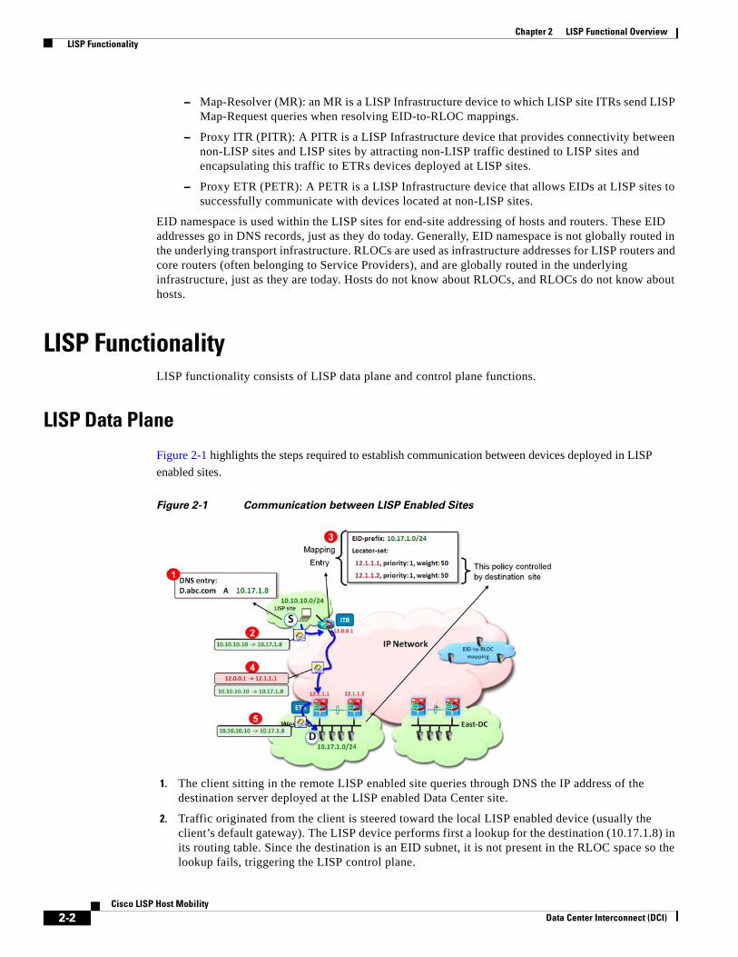
Figure 2-1 highlights the steps required to establish communication between devices deployed in LISP enabled sites.
Figure 2-1 Communication between LISP Enabled Sites
1. The client sitting in the remote LISP enabled site queries through DNS the IP address of the destination server deployed at the LISP enabled Data Center site.
2. Traffic originated from the client is steered toward the local LISP enabled device (usually the client’s default gateway). The LISP device performs first a lookup for the destination (10.17.1.8) in its routing table. Since the destination is an EID subnet, it is not present in the RLOC space so the lookup fails, triggering the LISP control plane.
2-2Cisco LISP Host Mobility
Data Center Interconnect (DCI)

Chapter 2 LISP Functional Overview LISP Functionality
Note In the current IOS and NX-OS LISP implementation, the LISP control plane is triggered if the lookup for the destination address produces no results (no match) or if the only available match is a default route.
3. The ITR receives valid mapping information from the Mapping database and populates its local map-cache (the following “LISP Control Plane” section on page 2-4 will clarify the control plane communication required for this to happen). Notice how the destination EID subnet (10.17.1.0/24) is associated to the RLOCs identifying both ETR devices at the Data Center LISP enabled site. Also, each entry has associated priority and weights values that are controlled by the destination site to influence the way inbound traffic is received from the transport infrastructure. The priority is used to determine if both ETR devices can be used to receive LISP encapsulated traffic destined to a local EID subnet (load-balancing scenario). The weight allows tuning the amount of traffic received by each ETR in a load-balancing scenario (hence the weight configuration makes sense only when specifying equal priorities for the local ETRs).
4. On the data-plane, the ITR performs LISP encapsulation of the original IP traffic and send it into the transport infrastructure, destined to one of the RLOCs of the Data Center ETRs. Assuming the priority and weight values are configured the same on the ETR devices (as shown in Communication between LISP Enabled Sites1), the selection of the specific ETR RLOC is done on a per flow basis based on hashing performed on the 5-tuple L3 and L4 information of the original client’s IP packet. The format of a LISP encapsulated packet is shown in Figure 2-2.
Figure 2-2 Format of a LISP Encapsulated Packet
As shown in Figure 2-2, LISP leverages a UDP encapsulation where the src port value is dynamically created and associated to each original flow to ensure better load-balancing of traffic across the transport infrastructure.
5. The ETR receives the packet, decapsulates it and sends it into the site toward the destination EID.
While Figure 2-1 shows only the North-to-South flow, a similar mechanism would be used for the return traffic originated by the DC EID and destined to the remote client, where the LISP devices would exchange their roles of ITRs and ETRs.
Figure 2-3shows the use of PxTR devices to establish communication between devices deployed in non-LISP sites and EIDs available in LISP enabled sites.
2-3Cisco LISP Host Mobility
Data Center Interconnect (DCI)
Chapter 2 LISP Functional Overview LISP Functionality
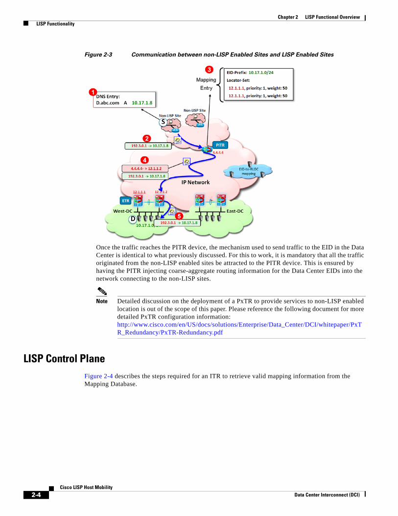
Figure 2-3 Communication between non-LISP Enabled Sites and LISP Enabled Sites
Once the traffic reaches the PITR device, the mechanism used to send traffic to the EID in the Data Center is identical to what previously discussed. For this to work, it is mandatory that all the traffic originated from the non-LISP enabled sites be attracted to the PITR device. This is ensured by having the PITR injecting coarse-aggregate routing information for the Data Center EIDs into the network connecting to the non-LISP sites.
Note Detailed discussion on the deployment of a PxTR to provide services to non-LISP enabled location is out of the scope of this paper. Please reference the following document for more detailed PxTR configuration information: http://www.cisco.com/en/US/docs/solutions/Enterprise/Data_Center/DCI/whitepaper/PxTR_Redundancy/PxTR-Redundancy.pdf
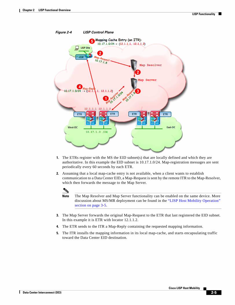
LISP Control PlaneFigure 2-4 describes the steps required for an ITR to retrieve valid mapping information from the Mapping Database.
2-4Cisco LISP Host Mobility
Data Center Interconnect (DCI)
Chapter 2 LISP Functional Overview LISP Functionality
Figure 2-4 LISP Control Plane
1. The ETRs register with the MS the EID subnet(s) that are locally defined and which they are authoritative. In this example the EID subnet is 10.17.1.0/24. Map-registration messages are sent periodically every 60 seconds by each ETR.
2. Assuming that a local map-cache entry is not available, when a client wants to establish communication to a Data Center EID, a Map-Request is sent by the remote ITR to the Map-Resolver, which then forwards the message to the Map Server.
Note The Map Resolver and Map Server functionality can be enabled on the same device. More discussion about MS/MR deployment can be found in the “LISP Host Mobility Operation” section on page 3-5.
3. The Map Server forwards the original Map-Request to the ETR that last registered the EID subnet. In this example it is ETR with locator 12.1.1.2.
4. The ETR sends to the ITR a Map-Reply containing the requested mapping information.
5. The ITR installs the mapping information in its local map-cache, and starts encapsulating traffic toward the Data Center EID destination.
2-5Cisco LISP Host Mobility
Data Center Interconnect (DCI)

Chapter 2 LISP Functional Overview LISP Functionality
2-6Cisco LISP Host Mobility
Data Center Interconnect (DCI)

Data Center Interconnect (DCI)
C H A P T E R 3
LISP Host Mobility SolutionThe traditional IP addressing model associates both Location and Identity to a single IP address space, making mobility a very cumbersome process since identity and location are tightly bundled together. Because LISP creates two separate name spaces, separating IP addresses into Route Locators (RLOC) and End-point Identifiers (EID), and provides a dynamic mapping mechanism between these two address families, EIDs can be found at different RLOCs based on the EID-RLOC mappings. RLOCs remain associated with the topology and are reachable by traditional routing. However, EIDs can change locations dynamically and are reachable via different RLOCs, depending on where an EID attaches to the network. In a virtualized data center deployment, EIDs can be directly assigned to Virtual Machines that are hence free to migrate between data center sites preserving their IP addressing information.
The decoupling of Identity from the topology is the core principle on which the LISP Host Mobility solution is based. It allows the End-point Identifier space to be mobile without impacting the routing that interconnects the Locator IP space. When a move is detected, as illustrated in Figure 3-1, the mappings between EIDs and RLOCs are updated by the new xTR. By updating the RLOC-to-EID mappings, traffic is redirected to the new locations without requiring the injection of host-routes or causing any churn in the underlying routing.
Figure 3-1 LISP Host Mobility
3-1Cisco LISP Host Mobility
Chapter 3 LISP Host Mobility Solution LISP Host Mobility Use Cases
LISP Host Mobility detects moves by configuring xTRs to compare the source in the IP header of traffic received from a host against a range of prefixes that are allowed to roam. These prefixes are defined as Dynamic-EIDs in the LISP Host Mobility solution. When deployed at the first hop router (xTR), LISP Host Mobility devices also provide adaptable and comprehensive first hop router functionality to service the IP gateway needs of the roaming devices that relocate.
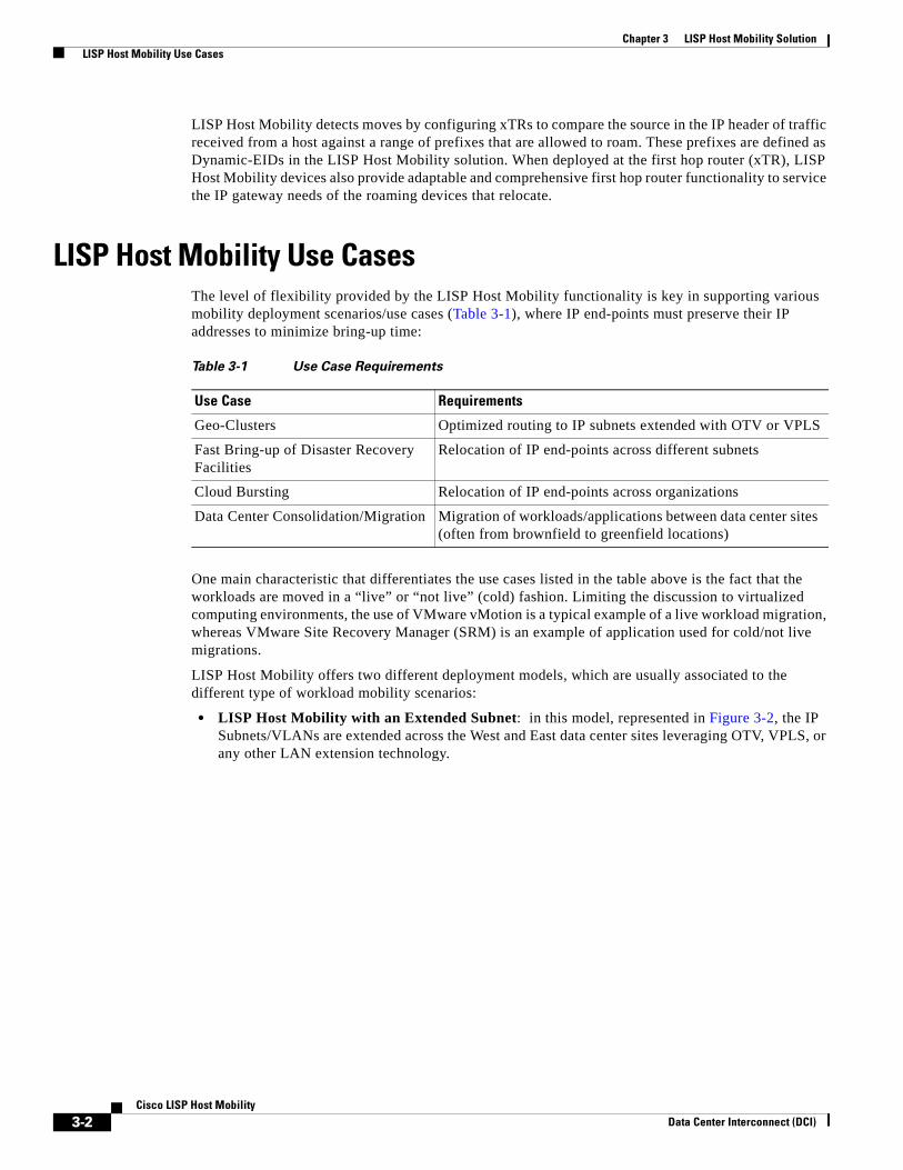
LISP Host Mobility Use CasesThe level of flexibility provided by the LISP Host Mobility functionality is key in supporting various mobility deployment scenarios/use cases (Table 3-1), where IP end-points must preserve their IP addresses to minimize bring-up time:
One main characteristic that differentiates the use cases listed in the table above is the fact that the workloads are moved in a “live” or “not live” (cold) fashion. Limiting the discussion to virtualized computing environments, the use of VMware vMotion is a typical example of a live workload migration, whereas VMware Site Recovery Manager (SRM) is an example of application used for cold/not live migrations.
LISP Host Mobility offers two different deployment models, which are usually associated to the different type of workload mobility scenarios:
• LISP Host Mobility with an Extended Subnet: in this model, represented in Figure 3-2, the IP Subnets/VLANs are extended across the West and East data center sites leveraging OTV, VPLS, or any other LAN extension technology.
Table 3-1 Use Case Requirements
Use Case Requirements
Geo-Clusters Optimized routing to IP subnets extended with OTV or VPLS
Fast Bring-up of Disaster Recovery Facilities
Relocation of IP end-points across different subnets
Cloud Bursting Relocation of IP end-points across organizations
Data Center Consolidation/Migration Migration of workloads/applications between data center sites (often from brownfield to greenfield locations)
3-2Cisco LISP Host Mobility
Data Center Interconnect (DCI)
Chapter 3 LISP Host Mobility Solution LISP Host Mobility Use Cases
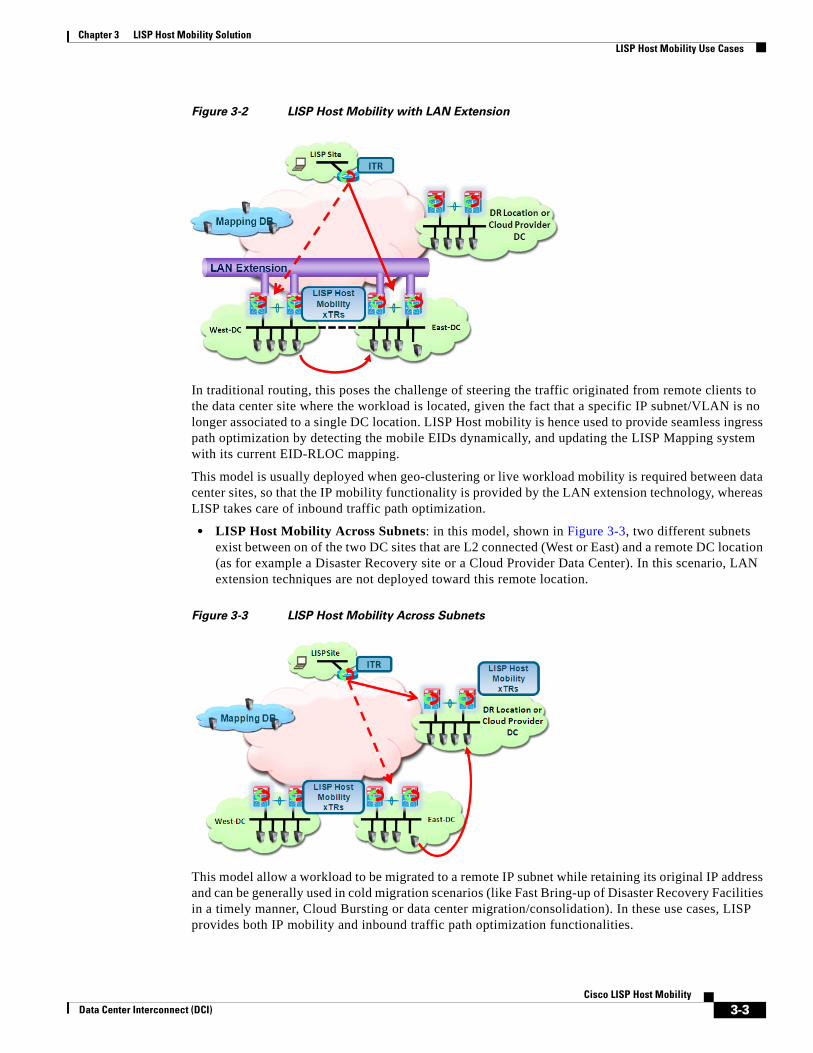
Figure 3-2 LISP Host Mobility with LAN Extension
In traditional routing, this poses the challenge of steering the traffic originated from remote clients to the data center site where the workload is located, given the fact that a specific IP subnet/VLAN is no longer associated to a single DC location. LISP Host mobility is hence used to provide seamless ingress path optimization by detecting the mobile EIDs dynamically, and updating the LISP Mapping system with its current EID-RLOC mapping.
This model is usually deployed when geo-clustering or live workload mobility is required between data center sites, so that the IP mobility functionality is provided by the LAN extension technology, whereas LISP takes care of inbound traffic path optimization.
• LISP Host Mobility Across Subnets: in this model, shown in Figure 3-3, two different subnets exist between on of the two DC sites that are L2 connected (West or East) and a remote DC location (as for example a Disaster Recovery site or a Cloud Provider Data Center). In this scenario, LAN extension techniques are not deployed toward this remote location.
Figure 3-3 LISP Host Mobility Across Subnets
This model allow a workload to be migrated to a remote IP subnet while retaining its original IP address and can be generally used in cold migration scenarios (like Fast Bring-up of Disaster Recovery Facilities in a timely manner, Cloud Bursting or data center migration/consolidation). In these use cases, LISP provides both IP mobility and inbound traffic path optimization functionalities.
3-3Cisco LISP Host Mobility
Data Center Interconnect (DCI)
Chapter 3 LISP Host Mobility Solution LISP Host Mobility Hardware and Software Prerequisites
This document discusses both of these modes in detail, and provides configuration steps and deployment recommendations for each of the LISP network elements.
LISP Host Mobility Hardware and Software PrerequisitesSome of the hardware and software prerequisites for deploying a LISP Host Mobility solution are listed below.
• At time of writing of this document, LISP Host Mobility is only supported on Nexus 7000 platforms and ISR and ISRG2 platforms. This functionality will also be supported in the ASR 1000 router in 2HCY12 timeframe. This document only covers the configuration and support of LISP Host Mobility on Nexus 7000 platforms.
• For the Nexus 7000 platform, LISP Host Mobility is supported in general Cisco NX-OS Release 5.2(1) or later. LISP Host Mobility support requires the Transport Services license, which includes both LISP and OTV.
• From a switch modules perspective, LISP is currently supported only in N7K-M132XP-12 and in N7K-M132XP-12L linecards.
Caution EPLD upgrade to the minimum version 186.008 is required for these linecards. For more information on how to upgrade the EPLDs refer to link:http://www.cisco.com/en/US/docs/switches/datacenter/sw/4_0/epld/release/notes/epld_rn.html
LISP is also supported on Nexus 7000 leveraging F1-series modules for site-facing interfaces, as long as one of the M1-32 series cards mentioned above is available in the chassis. This is because only M1-32 linecards can perform LISP encapsulation/decapsulation in HW, so it is required for L2 traffic received on F1 interfaces to be internally sent to these M1 cards for that purpose. This functionality available on Nexus 7000 platforms is known as "proxy routing".
Note Only the F1 series line cards support proxy mode at the time of writing this document. Proxy mode is not supported between M-series cards, so the site facing interfaces can only be N7K-M132XP-12, N7K-M132XP-12L or F1-series linecards.
Figure 3-4 shows the specific HW deployment models for LISP Host Mobility.
3-4Cisco LISP Host Mobility
Data Center Interconnect (DCI)
Chapter 3 LISP Host Mobility Solution LISP Host Mobility Operation
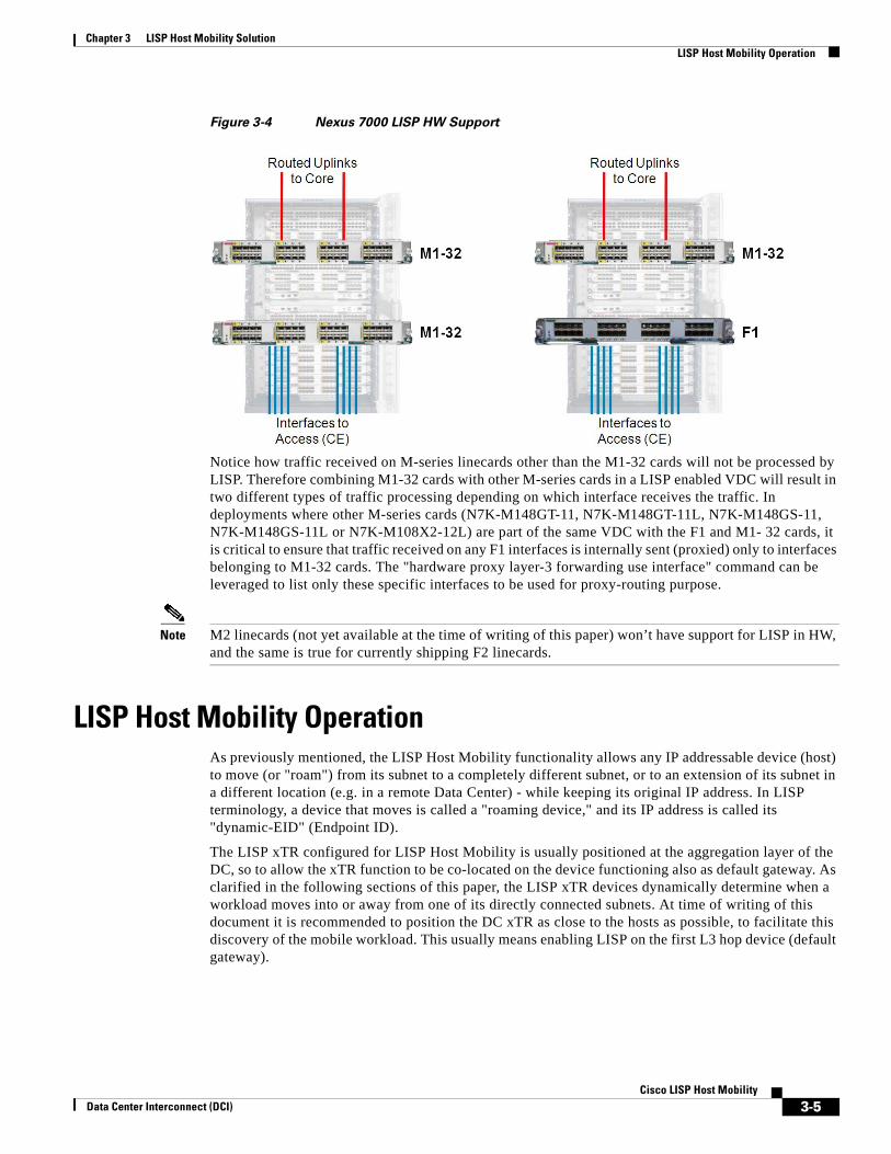
Figure 3-4 Nexus 7000 LISP HW Support
Notice how traffic received on M-series linecards other than the M1-32 cards will not be processed by LISP. Therefore combining M1-32 cards with other M-series cards in a LISP enabled VDC will result in two different types of traffic processing depending on which interface receives the traffic. In deployments where other M-series cards (N7K-M148GT-11, N7K-M148GT-11L, N7K-M148GS-11, N7K-M148GS-11L or N7K-M108X2-12L) are part of the same VDC with the F1 and M1- 32 cards, it is critical to ensure that traffic received on any F1 interfaces is internally sent (proxied) only to interfaces belonging to M1-32 cards. The "hardware proxy layer-3 forwarding use interface" command can be leveraged to list only these specific interfaces to be used for proxy-routing purpose.
Note M2 linecards (not yet available at the time of writing of this paper) won’t have support for LISP in HW, and the same is true for currently shipping F2 linecards.
LISP Host Mobility OperationAs previously mentioned, the LISP Host Mobility functionality allows any IP addressable device (host) to move (or "roam") from its subnet to a completely different subnet, or to an extension of its subnet in a different location (e.g. in a remote Data Center) - while keeping its original IP address. In LISP terminology, a device that moves is called a "roaming device," and its IP address is called its "dynamic-EID" (Endpoint ID).
The LISP xTR configured for LISP Host Mobility is usually positioned at the aggregation layer of the DC, so to allow the xTR function to be co-located on the device functioning also as default gateway. As clarified in the following sections of this paper, the LISP xTR devices dynamically determine when a workload moves into or away from one of its directly connected subnets. At time of writing of this document it is recommended to position the DC xTR as close to the hosts as possible, to facilitate this discovery of the mobile workload. This usually means enabling LISP on the first L3 hop device (default gateway).
3-5Cisco LISP Host Mobility
Data Center Interconnect (DCI)
Chapter 3 LISP Host Mobility Solution LISP Host Mobility Operation
Map-Server and Map-Resolver Deployment ConsiderationsAs previously discussed, the Map-Server and Map-Resolver are key components in a LISP deployment. They provide capabilities to store and resolve the EID-to-RLOC mapping information for the LISP routers to route between LISP sites. The Map-Server is a network infrastructure component that learns EID-to-RLOC mapping entries from ETRs that are authoritative sources and that publish (register) their EID-to-RLOC mapping relationships with the Map-Server. A Map-Resolver is a network infrastructure component which accepts LISP encapsulated Map-Requests, typically from an ITR, and finds the appropriate EID-to-RLOC mapping by checking with a co-located Map-Server (typically), or by consulting the distributed mapping system.
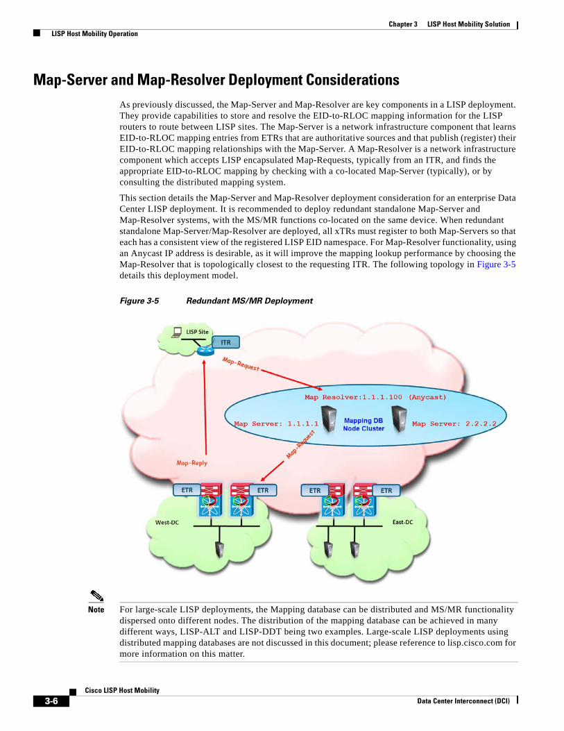
This section details the Map-Server and Map-Resolver deployment consideration for an enterprise Data Center LISP deployment. It is recommended to deploy redundant standalone Map-Server and Map-Resolver systems, with the MS/MR functions co-located on the same device. When redundant standalone Map-Server/Map-Resolver are deployed, all xTRs must register to both Map-Servers so that each has a consistent view of the registered LISP EID namespace. For Map-Resolver functionality, using an Anycast IP address is desirable, as it will improve the mapping lookup performance by choosing the Map-Resolver that is topologically closest to the requesting ITR. The following topology in Figure 3-5 details this deployment model.
Figure 3-5 Redundant MS/MR Deployment
Note For large-scale LISP deployments, the Mapping database can be distributed and MS/MR functionality dispersed onto different nodes. The distribution of the mapping database can be achieved in many different ways, LISP-ALT and LISP-DDT being two examples. Large-scale LISP deployments using distributed mapping databases are not discussed in this document; please reference to lisp.cisco.com for more information on this matter.
3-6Cisco LISP Host Mobility
Data Center Interconnect (DCI)

Chapter 3 LISP Host Mobility Solution LISP Host Mobility Operation
It is worth noticing that a redundant standalone MS/MR model can be deployed by leveraging dedicated systems to perform these mapping functionalities (shown in Figure 3-5), or alternatively by deploying the Map-Server and Map-Resolver functionalities concurrently on the same network device already performing the xTR role (Figure 3-6).
Figure 3-6 Co-locating MS/MR and xTR Functionalities
The co-located model shown above is particularly advantageous as it reduces the overall number of managed devices required to roll out a LISP Host Mobility solution. Notice that the required configuration in both scenarios would remain identical, leveraging unique IP addresses to identify the Map-Servers and an Anycast IP address for the Map-Resolver.
Dynamic-EID Detection When a dynamic-EID roams between data center sites, the local LISP Host Mobility xTRs need to detect its existence. As it will be discussed in detail in the next chapter, this information is then used to update the content of the mapping database, allowing the steering of the traffic to the new data center location.
Figure 3-7 shows the dynamic detection of an EID migrated between DC sites.
3-7Cisco LISP Host Mobility
Data Center Interconnect (DCI)
Chapter 3 LISP Host Mobility Solution LISP Host Mobility Operation
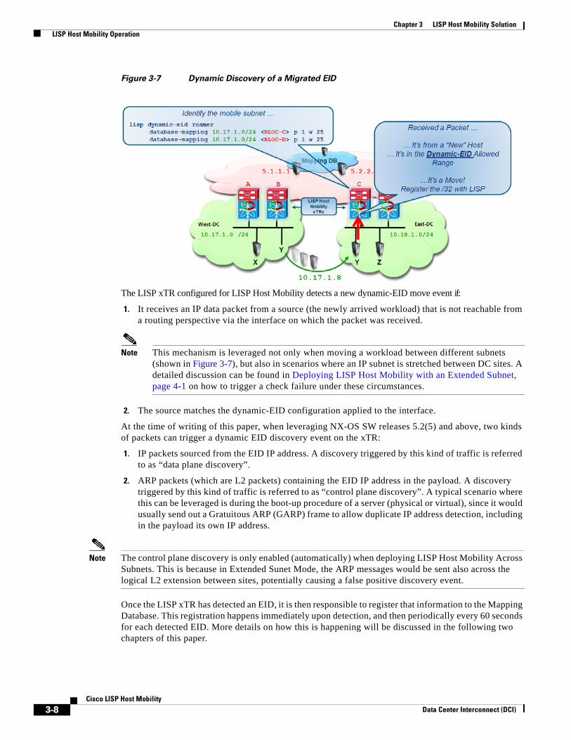
Figure 3-7 Dynamic Discovery of a Migrated EID
The LISP xTR configured for LISP Host Mobility detects a new dynamic-EID move event if:
1. It receives an IP data packet from a source (the newly arrived workload) that is not reachable from a routing perspective via the interface on which the packet was received.
Note This mechanism is leveraged not only when moving a workload between different subnets (shown in Figure 3-7), but also in scenarios where an IP subnet is stretched between DC sites. A detailed discussion can be found in Deploying LISP Host Mobility with an Extended Subnet, page 4-1 on how to trigger a check failure under these circumstances.
2. The source matches the dynamic-EID configuration applied to the interface.
At the time of writing of this paper, when leveraging NX-OS SW releases 5.2(5) and above, two kinds of packets can trigger a dynamic EID discovery event on the xTR:
1. IP packets sourced from the EID IP address. A discovery triggered by this kind of traffic is referred to as “data plane discovery”.
2. ARP packets (which are L2 packets) containing the EID IP address in the payload. A discovery triggered by this kind of traffic is referred to as “control plane discovery”. A typical scenario where this can be leveraged is during the boot-up procedure of a server (physical or virtual), since it would usually send out a Gratuitous ARP (GARP) frame to allow duplicate IP address detection, including in the payload its own IP address.
Note The control plane discovery is only enabled (automatically) when deploying LISP Host Mobility Across Subnets. This is because in Extended Sunet Mode, the ARP messages would be sent also across the logical L2 extension between sites, potentially causing a false positive discovery event.
Once the LISP xTR has detected an EID, it is then responsible to register that information to the Mapping Database. This registration happens immediately upon detection, and then periodically every 60 seconds for each detected EID. More details on how this is happening will be discussed in the following two chapters of this paper.
3-8Cisco LISP Host Mobility
Data Center Interconnect (DCI)
Data Center Interconnect (DCI)
C H A P T E R 4
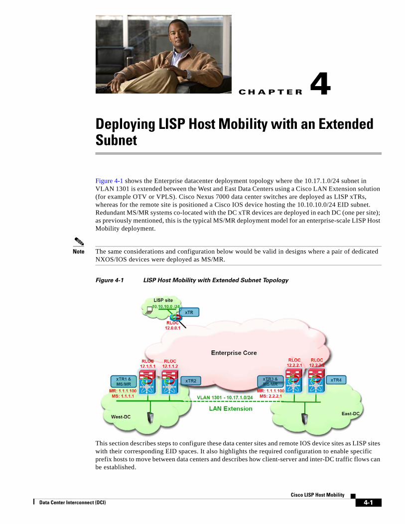
Deploying LISP Host Mobility with an Extended SubnetFigure 4-1 shows the Enterprise datacenter deployment topology where the 10.17.1.0/24 subnet in VLAN 1301 is extended between the West and East Data Centers using a Cisco LAN Extension solution (for example OTV or VPLS). Cisco Nexus 7000 data center switches are deployed as LISP xTRs, whereas for the remote site is positioned a Cisco IOS device hosting the 10.10.10.0/24 EID subnet. Redundant MS/MR systems co-located with the DC xTR devices are deployed in each DC (one per site); as previously mentioned, this is the typical MS/MR deployment model for an enterprise-scale LISP Host Mobility deployment.
Note The same considerations and configuration below would be valid in designs where a pair of dedicated NXOS/IOS devices were deployed as MS/MR.
Figure 4-1 LISP Host Mobility with Extended Subnet Topology
This section describes steps to configure these data center sites and remote IOS device sites as LISP sites with their corresponding EID spaces. It also highlights the required configuration to enable specific prefix hosts to move between data centers and describes how client-server and inter-DC traffic flows can be established.
4-1Cisco LISP Host Mobility

Chapter 4 Deploying LISP Host Mobility with an Extended Subnet LISP Host Mobility with an Extended Subnet Prerequisites
LISP Host Mobility with an Extended Subnet PrerequisitesBefore discussing the specific LISP Host Mobility functionality with an Extended Subnet Mode, is it important to highlight some important solution prerequisites:
• HSRP Hello messages should not be exchanged across the data center sites, allowing for the creation of an active-active HSRP setup. This is mainly done to provide an active default gateway in each physical Data Center location and avoid asymmetric traffic paths when optimizing ingress traffic with LISP (HSRP localization handles only the egress flows). Usually HSRP filtering is configured, leveraging ACLs to drop Hellos and prevent the exchange across the LAN extension connection. For more details on how to achieve HSRP localization when deploying OTV, please refer to paper below:
http://www.cisco.com/en/US/docs/solutions/Enterprise/Data_Center/DCI/whitepaper/DCI3_OTV_Intro_WP.pdf
• The default gateway Virtual MAC (vMAC) and IP addresses (vIP) in both data centers should remain consistent, as the mobile workload would most likely continue to send packets to the same GW IP address after the live mobility event is completed. Virtual MAC consistency is usually achieved in Extended Subnet mode by configuring the same HSRP group associated to the same subnet in separate Data Center sites. In scenarios where the same HSRP group is not configured, an alternative approach consists of manually configuring a static vMAC as part of the HSRP configuration.
• OTV or any other deployed LAN extension solution must have multicast support over the extended L2 subnet for the proper operation of LISP Host Mobility in an extended subnet mode. This is because the LISP xTRs deployed across data center sites leverage the L2 logical connection to exchange multicast control plane messages carrying information about the different EIDs that were discovered in each site.
LISP Host Mobility with an Extended Subnet: Sample ConfigWith reference to Figure 4-1, the following are the basic configuration steps required on the various devices in the network to enable LISP Host Mobility.
Nexus 7000 N7K1A and N7K1B West DC-xTRs ConfigurationThe required configurations for the xTRs deployed in the West DC is shown in Figure 4-2.
4-2Cisco LISP Host Mobility
Data Center Interconnect (DCI)

Chapter 4 Deploying LISP Host Mobility with an Extended Subnet LISP Host Mobility with an Extended Subnet: Sample Config
Figure 4-2 LISP Host Mobility with Extended Subnet Configuration for xTRs in West DC
As it is easy to notice, the LISP configuration is pretty much identical across the two devices part of the same DC site. The following steps explanation of the various portions of the configuration.
• As first step, it is required to enable the LISP functionality on the Nexus devices and specify that they are going to perform the roles of LISP ETR (for decapsulating LISP traffic received from the L3 domain of the network) and ITR (for encapsulating LISP traffic destined to remote locations).
feature lisp ip lisp itr-etr
• A global database mapping is then configured, including an aggregate prefix that ideally identifies all the IP subnets deployed in this specific Data Center site. Notice that this aggregate prefix may include both “mobile subnets” and “static subnets”. An additional piece of configuration is required to specifically identify these mobile subnets, as discussed later.
ip lisp database-mapping 10.17.0.0/16 12.1.1.1 priority 1 weight 50ip lisp database-mapping 10.17.0.0/16 12.1.1.2 priority 1 weight 50
The mapping above associates the aggregate prefix 10.17.0.0/16 to two RLOC IP addresses, which are the RLOCs identifying each xTR devices at this local DC. The recommendation is to define a loopback interface on each device as RLOC, so that communication to that IP address will remain successful as long as a valid L3 path connects the xTR to the L3 domain of the network.
Notice also how a priority and a weight can be associated to each mapping statement: these values can be tuned to influence the inbound traffic, preferring for example the path through a specific xTR. In the configuration above the values are identical to ensure that inbound traffic can be load-balanced across both DC xTRs.
Note The definition of the global database-mapping statements is particularly important to enable routing between mobile and not mobile subnets, as will be explained in detail in the “East-West Traffic Flows Considerations” section on page 4-19.
4-3Cisco LISP Host Mobility
Data Center Interconnect (DCI)
Chapter 4 Deploying LISP Host Mobility with an Extended Subnet LISP Host Mobility with an Extended Subnet: Sample Config
• The next step consists then in defining the IP addresses of the Map-Servers and Map-Resolvers. ip lisp itr map-resolver 1.1.1.100ip lisp etr map-server 1.1.1.1 key abcd ip lisp etr map-server 2.2.2.1 key abcd
As already mentioned, in a typical Enterprise deployment, two devices perform the roles of MS/MR and work in a complete standalone fashion. As a consequence, on the xTRs we need to specify the IP addresses of the two Map-Servers (so that each xTR can register with both MS the EID prefixes) and the Anycast IP address of the Map-Resolver (so that the Map-Requests will be received by the MR that is closer from a routing perspective).
• A dynamic mapping is then required to identify the IP subnets to which the mobile workloads belong. When deploying LISP Host Mobility with Extended Subnet, these are the IP subnets/VLANs that are extended between DC sites.
lisp dynamic-eid EXTENDED_SUBNET database-mapping 10.17.1.0/24 12.1.1.1 priority 1 weight 50 database-mapping 10.17.1.0/24 12.1.1.2 priority 1 weight 50 map-notify-group 239.1.1.1
In this example, the mobile subnet is a /24 prefix, which is associated to the same two RLOCs previously used for the global mapping. Priorities and weights are kept the same also in this case, to benefit of inbound load balancing for traffic destined to the mobile subnet. A multicast address (named “map-notify-group”) must also be associated to the dynamic-eid mapping. Its use will be clarified in the following sections of the document.
Some additional considerations around the length of the network prefix specified in the dynamic-eid mapping:
– If multiple mobile subnets are configured, it is required to define a different “lisp dynamic-eid” construct for each subnet and not to define a coarser prefix that includes all the mobile subnets. The multicast address of the map-notify-group can be the same across multiple constructs.
– The mask associated to the dynamic-eid prefix should always be more specific that the one used in the global mapping statements.
– The mask associated to the dynamic-eid prefix should match the length of the network mask of the interface (usually an SVI) where the mobility commands are configured. This is under the assumption (usually valid) that mobility should be enabled for the workloads belonging to the entire subnet.
• Finally, the LISP dynamic-eid policy configuration must be applied under the L3 interface connecting to the mobile subnet. Since the DC xTR is positioned at the aggregation layer, the L3 interface is usually a VLAN Interface (SVI). Notice how this is the only piece of configuration that is different between the two xTRs belonging to the same site (because of IP addressing and HSRP commands).
N7K1Ainterface vlan 1301 ip address 10.17.1.3/24 lisp mobility EXTENDED_SUBNET lisp extended-subnet-mode hsrp 1 preempt delay reload 300 priority 130 ip 10.17.1.1
N7K1Binterface vlan 1301
4-4Cisco LISP Host Mobility
Data Center Interconnect (DCI)
Chapter 4 Deploying LISP Host Mobility with an Extended Subnet LISP Host Mobility with an Extended Subnet: Sample Config
ip address 10.17.1.2/24 lisp mobility EXTENDED_SUBNET lisp extended-subnet-mode hsrp 1 priority 120 ip 10.17.1.1
The “lisp mobility” command is used to attach the dynamic-eid construct to this interface, whereas “lisp extended-subnet-mode” is used to specify that the mobile subnet is extended across data center sites.
Note No specific multicast configuration (for example enabling PIM) is required under the SVI. Simply configuring LISP Host Mobility on the interface ensures that map-notify-group multicast frames can be sent and received successfully on the SVI interface (both for communication with the local peer xTR and for exchanging messages with the remote xTR devices across the logical LAN L2 extension between sites).
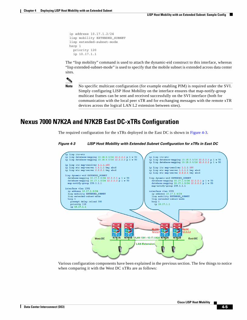
Nexus 7000 N7K2A and N7K2B East DC-xTRs ConfigurationThe required configuration for the xTRs deployed in the East DC is shown in Figure 4-3.
Figure 4-3 LISP Host Mobility with Extended Subnet Configuration for xTRs in East DC
Various configuration components have been explained in the previous section. The few things to notice when comparing it with the West DC xTRs are as follows:
4-5Cisco LISP Host Mobility
Data Center Interconnect (DCI)

Chapter 4 Deploying LISP Host Mobility with an Extended Subnet LISP Host Mobility with an Extended Subnet: Sample Config
• The global mapping is different from the one configured on the West DC xTRs. Again, the assumption here is that the IP subnets deployed in the East site can be aggregated by a unique IP prefix (10.18.0.0/16 in this case). Also, the RLOC associated to the global prefixes are now identifying the xTR devices in the East DC site.
• The prefix in the dynamic-eid mapping relative to the mobile subnet must be identical to the one defined on the West xTRs, since identifies the IP subnet extended across sites. This is the reason why 10.17.1.0/24 is specified also on the xTRs in the East DC. However, the RLOCs associated to the mobile subnet are now identifying the xTRs in the East site.
Note The same considerations would apply if we also had a part of the East DC address space that was configured as a mobile subnet extended across sites (for example 10.18.1.0/24).
• The map-notify-group associated to the dynamic-eid mapping must be identical to the one configured for the xTRs in the West site. This is because it will be used for control plane communication by all the xTRs connected to the extended subnet. The multicast communication will be established across the LAN extension logical connection (deployed with OTV, VPLS, etc.), so it is important to ensure that whatever technology is deployed to provide LAN extension services, multicast frames can be exchanged between sites.
• Notice how the HSRP VIP configured is the same (10.17.1.1) used on the West xTRs, as well as the HSRP group number (“hsrp 1”) that creates the same vMAC. This is required to ensure that a workload moved to the East site can continue to communicate with the local default gateway without having to refresh its ARP cache. As previously mentioned, it is also required to filter HSRP hellos across the logical LAN extension connection to ensure that an Active HSRP device can be deployed in each data center site.
Remote Site Cisco IOS-xTR ConfigurationThe configuration of the branch xTR is shown in Figure 4-4.
Figure 4-4 Remote xTR IOS Configuration
4-6Cisco LISP Host Mobility
Data Center Interconnect (DCI)
Chapter 4 Deploying LISP Host Mobility with an Extended Subnet LISP Host Mobility with an Extended Subnet: Sample Config
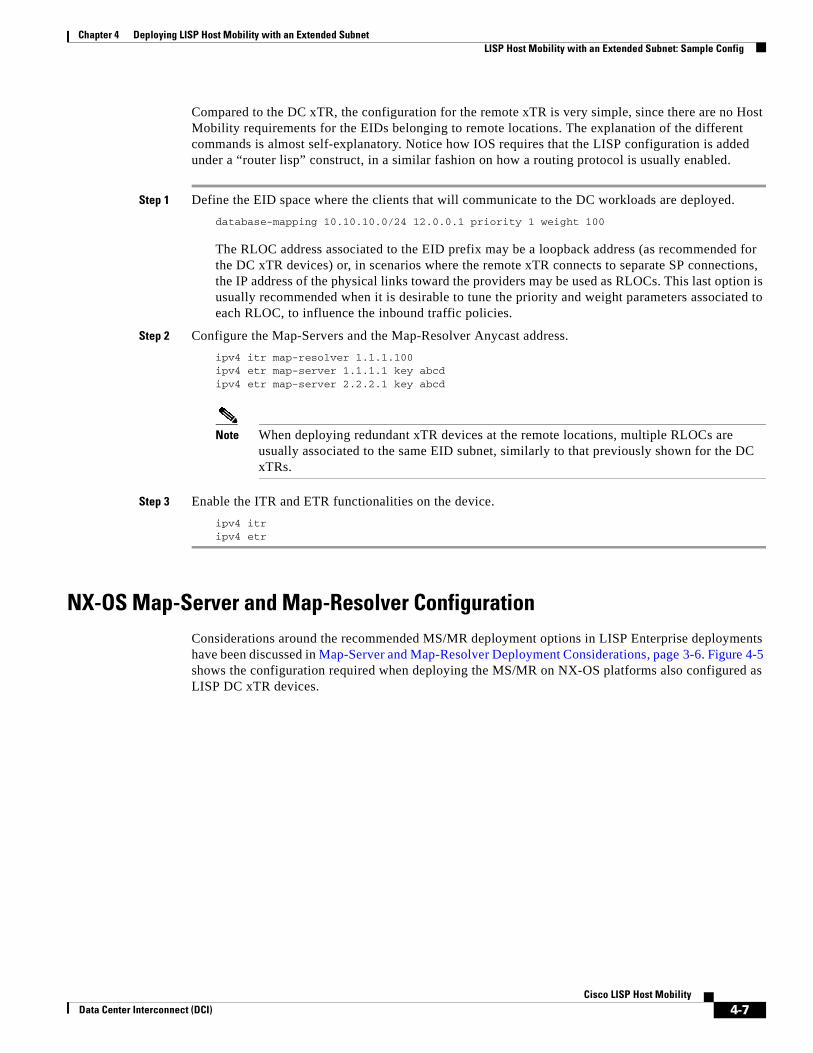
Compared to the DC xTR, the configuration for the remote xTR is very simple, since there are no Host Mobility requirements for the EIDs belonging to remote locations. The explanation of the different commands is almost self-explanatory. Notice how IOS requires that the LISP configuration is added under a “router lisp” construct, in a similar fashion on how a routing protocol is usually enabled.
Step 1 Define the EID space where the clients that will communicate to the DC workloads are deployed.database-mapping 10.10.10.0/24 12.0.0.1 priority 1 weight 100
The RLOC address associated to the EID prefix may be a loopback address (as recommended for the DC xTR devices) or, in scenarios where the remote xTR connects to separate SP connections, the IP address of the physical links toward the providers may be used as RLOCs. This last option is usually recommended when it is desirable to tune the priority and weight parameters associated to each RLOC, to influence the inbound traffic policies.
Step 2 Configure the Map-Servers and the Map-Resolver Anycast address.ipv4 itr map-resolver 1.1.1.100ipv4 etr map-server 1.1.1.1 key abcdipv4 etr map-server 2.2.2.1 key abcd
Note When deploying redundant xTR devices at the remote locations, multiple RLOCs are usually associated to the same EID subnet, similarly to that previously shown for the DC xTRs.
Step 3 Enable the ITR and ETR functionalities on the device.ipv4 itripv4 etr
NX-OS Map-Server and Map-Resolver ConfigurationConsiderations around the recommended MS/MR deployment options in LISP Enterprise deployments have been discussed in Map-Server and Map-Resolver Deployment Considerations, page 3-6. Figure 4-5 shows the configuration required when deploying the MS/MR on NX-OS platforms also configured as LISP DC xTR devices.
4-7Cisco LISP Host Mobility
Data Center Interconnect (DCI)

Chapter 4 Deploying LISP Host Mobility with an Extended Subnet LISP Host Mobility with an Extended Subnet: Sample Config
Figure 4-5 NX-OS and IOS MS/MR Configurations
Notice how the configuration on the two MS/MR devices is basically identical, with the only exception of the IP address used as Map-Server identifier. The different parts of the NX-OS configuration are explained below (the equivalent IOS configuration is also shown in scenarios where dedicated standalone MS/MR are deployed).
Step 1 Enable the MS and MR functionalities on the device.
NX-OS
feature lisp
ip lisp map-resolver
ip lisp map-server
IOS
router lisp
ipv4 map-server
ipv4 map-resolver
Step 2 Define the Loopback interfaces used as IP addresses for the Map-Resolver and Map-Server functions.
NX-OS
interface loopback0
description Map-Resolver IP Address
ip address 1.1.1.100/32
!
interface loopback1
description Map-Server IP Address
ip address 1.1.1.1/32
4-8Cisco LISP Host Mobility
Data Center Interconnect (DCI)

Chapter 4 Deploying LISP Host Mobility with an Extended Subnet LISP Host Mobility with an Extended Subnet: Sample Config
IOS
interface loopback0
description Map-Resolver IP Address
ip address 1.1.1.100 255.255.255.255
!
interface loopback1
description Map-Server IP Address
ip address 1.1.1.1 255.255.255.255
Both Map-Resolvers in Figure 4-5 are configured with the same IP address (Anycast IP address), so that Map-Requests originated from LISP ITR devices can be received on the MR device that is “closer” from a routing table point of view. A unique IP address is instead leveraged for the Map-Server, because the LISP ETRs must register their EID subnets with both standalone Map-Servers.
Step 3 Configure the remote branch site.
NX-OS
lisp site BRANCH
eid-prefix 10.10.10.0/24
authentication-key 0 abcd
IOS
router lisp
site BRANCH
authentication-key abcd
eid-prefix 10.10.10.0/24
Step 4 Configure the West and East Data Center sites.
NX-OS
lisp site WEST_DATA_CENTER
eid-prefix 10.17.0.0/16 accept-more-specifics
authentication-key 0 abcd
!
lisp site EAST_DATA_CENTER
eid-prefix 10.18.0.0/16 accept-more-specifics
authentication-key 0 abcd
IOS
site WEST_DATA_CENTER
authentication-key abcd
eid-prefix 10.17.0.0/16 accept-more-specifics
!
site EAST_DATA_CENTER
authentication-key abcd
eid-prefix 10.18.0.0/16 accept-more-specifics
It is important to notice the “accept-more-specifics” keyword associated to the DC EID prefix. This must be configured to the sites where LISP Host Mobility is enabled, since specific /32 prefixes that are part of the larger aggregate prefix will be registered by the DC xTRs. The reasoning behind this behavior will be clarified in detail in the following section.
4-9Cisco LISP Host Mobility
Data Center Interconnect (DCI)
Chapter 4 Deploying LISP Host Mobility with an Extended Subnet Remote Clients Communicating to EIDs before a Mobility Event
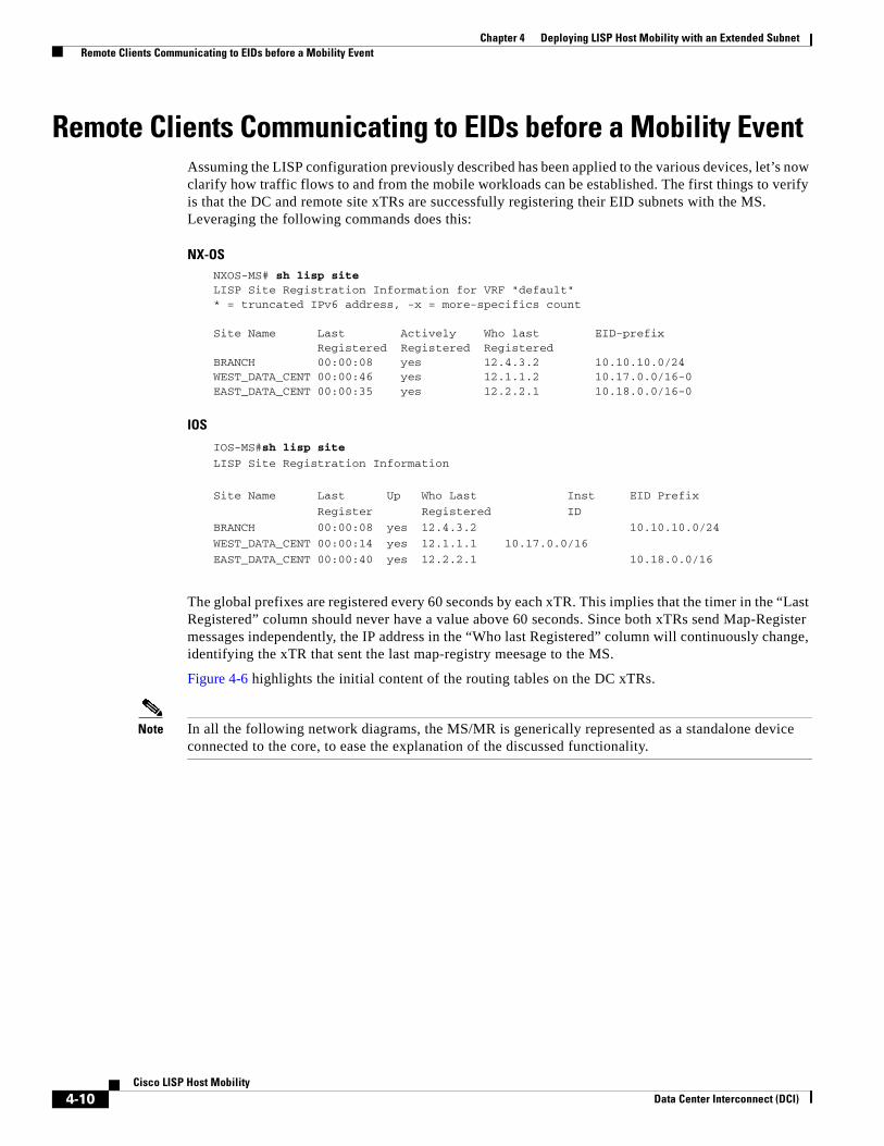
Remote Clients Communicating to EIDs before a Mobility Event Assuming the LISP configuration previously described has been applied to the various devices, let’s now clarify how traffic flows to and from the mobile workloads can be established. The first things to verify is that the DC and remote site xTRs are successfully registering their EID subnets with the MS. Leveraging the following commands does this:
NX-OSNXOS-MS# sh lisp siteLISP Site Registration Information for VRF "default"* = truncated IPv6 address, -x = more-specifics count
Site Name Last Actively Who last EID-prefix Registered Registered RegisteredBRANCH 00:00:08 yes 12.4.3.2 10.10.10.0/24WEST_DATA_CENT 00:00:46 yes 12.1.1.2 10.17.0.0/16-0EAST_DATA_CENT 00:00:35 yes 12.2.2.1 10.18.0.0/16-0
IOS
IOS-MS#sh lisp site
LISP Site Registration Information
Site Name Last Up Who Last Inst EID Prefix
Register Registered ID
BRANCH 00:00:08 yes 12.4.3.2 10.10.10.0/24
WEST_DATA_CENT 00:00:14 yes 12.1.1.1 10.17.0.0/16
EAST_DATA_CENT 00:00:40 yes 12.2.2.1 10.18.0.0/16
The global prefixes are registered every 60 seconds by each xTR. This implies that the timer in the “Last Registered” column should never have a value above 60 seconds. Since both xTRs send Map-Register messages independently, the IP address in the “Who last Registered” column will continuously change, identifying the xTR that sent the last map-registry meesage to the MS.
Figure 4-6 highlights the initial content of the routing tables on the DC xTRs.
Note In all the following network diagrams, the MS/MR is generically represented as a standalone device connected to the core, to ease the explanation of the discussed functionality.
4-10Cisco LISP Host Mobility
Data Center Interconnect (DCI)
Chapter 4 Deploying LISP Host Mobility with an Extended Subnet Remote Clients Communicating to EIDs before a Mobility Event
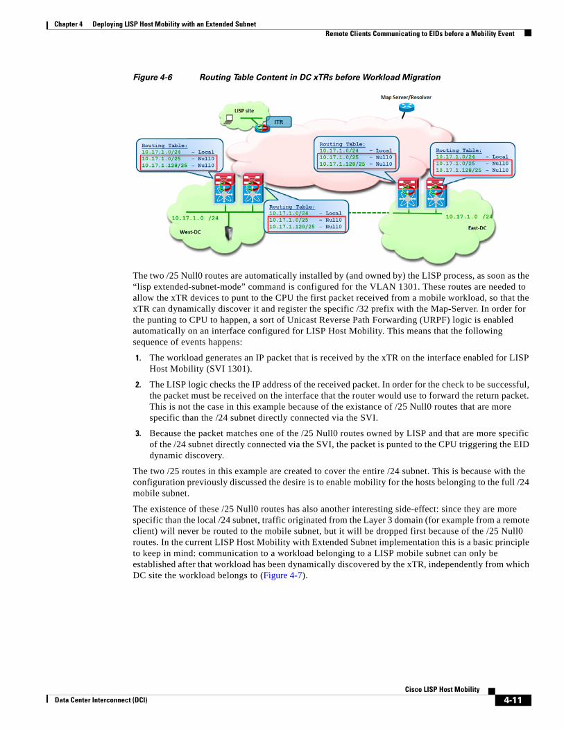
Figure 4-6 Routing Table Content in DC xTRs before Workload Migration
The two /25 Null0 routes are automatically installed by (and owned by) the LISP process, as soon as the “lisp extended-subnet-mode” command is configured for the VLAN 1301. These routes are needed to allow the xTR devices to punt to the CPU the first packet received from a mobile workload, so that the xTR can dynamically discover it and register the specific /32 prefix with the Map-Server. In order for the punting to CPU to happen, a sort of Unicast Reverse Path Forwarding (URPF) logic is enabled automatically on an interface configured for LISP Host Mobility. This means that the following sequence of events happens:
1. The workload generates an IP packet that is received by the xTR on the interface enabled for LISP Host Mobility (SVI 1301).
2. The LISP logic checks the IP address of the received packet. In order for the check to be successful, the packet must be received on the interface that the router would use to forward the return packet. This is not the case in this example because of the existance of /25 Null0 routes that are more specific than the /24 subnet directly connected via the SVI.
3. Because the packet matches one of the /25 Null0 routes owned by LISP and that are more specific of the /24 subnet directly connected via the SVI, the packet is punted to the CPU triggering the EID dynamic discovery.
The two /25 routes in this example are created to cover the entire /24 subnet. This is because with the configuration previously discussed the desire is to enable mobility for the hosts belonging to the full /24 mobile subnet.
The existence of these /25 Null0 routes has also another interesting side-effect: since they are more specific than the local /24 subnet, traffic originated from the Layer 3 domain (for example from a remote client) will never be routed to the mobile subnet, but it will be dropped first because of the /25 Null0 routes. In the current LISP Host Mobility with Extended Subnet implementation this is a basic principle to keep in mind: communication to a workload belonging to a LISP mobile subnet can only be established after that workload has been dynamically discovered by the xTR, independently from which DC site the workload belongs to (Figure 4-7).
4-11Cisco LISP Host Mobility
Data Center Interconnect (DCI)

Chapter 4 Deploying LISP Host Mobility with an Extended Subnet Remote Clients Communicating to EIDs before a Mobility Event
Figure 4-7 Dropping Client Initiated Traffic Flows
Hence, to establish a successful client-server communication, we first need to discover the EID in the West DC location, following the sequence of events shown in Figure 4-8.
Figure 4-8 Initial Discovery of an EID in West DC
1. The workload sends out an IP packet that is intercepted by one of the xTRs and punted to the CPU, triggering a data-plan driven EID discovery event. Notice that for this to happen, the packet must be an IP packet containing the source IP address of the EID. Once the EID is discovered, it is added to the dynamic-eid table of the discovering xTR, as shown below.N7K1A# show lisp dyn summary
4-12Cisco LISP Host Mobility
Data Center Interconnect (DCI)
Chapter 4 Deploying LISP Host Mobility with an Extended Subnet Remote Clients Communicating to EIDs before a Mobility Event
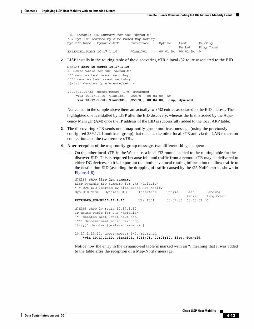
LISP Dynamic EID Summary for VRF "default"* = Dyn-EID learned by site-based Map-NotifyDyn-EID Name Dynamic-EID Interface Uptime Last Pending Packet Ping CountEXTENDED_SUBNE 10.17.1.10 Vlan1301 00:01:54 00:01:54 0
2. LISP installs in the routing table of the discovering xTR a local /32 route associated to the EID.N7K1A# show ip route 10.17.1.10IP Route Table for VRF "default"'*' denotes best ucast next-hop'**' denotes best mcast next-hop'[x/y]' denotes [preference/metric]
10.17.1.10/32, ubest/mbest: 1/0, attached *via 10.17.1.10, Vlan1301, [250/0], 00:04:00, am via 10.17.1.10, Vlan1301, [251/0], 00:04:00, lisp, dyn-eid
Notice that in the sample above there are actually two /32 entries associated to the EID address. The highlighted one is installed by LISP after the EID discovery, whereas the first is added by the Adja-cency Manager (AM) once the IP address of the EID is successfully added to the local ARP table.
3. The discovering xTR sends out a map-notify-group multicast message (using the previously configured 239.1.1.1 multicast group) that reaches the other local xTR and via the LAN extension connection also the two remote xTRs.
4. After reception of the map-notify-group message, two different things happen:
– On the other local xTR in the West site, a local /32 route is added to the routing table for the discover EID. This is required because inbound traffic from a remote xTR may be delivered to either DC devices, so it is important that both have local routing information to allow traffic to the destination EID (avoiding the dropping of traffic caused by the /25 Null0 entries shown in Figure 4-8).N7K1B# show lisp dyn summary LISP Dynamic EID Summary for VRF "default"* = Dyn-EID learned by site-based Map-NotifyDyn-EID Name Dynamic-EID Interface Uptime Last Pending Packet Ping CountEXTENDED_SUBNE*10.17.1.10 Vlan1301 00:07:00 00:00:52 0
N7K1B# show ip route 10.17.1.10IP Route Table for VRF "default"'*' denotes best ucast next-hop'**' denotes best mcast next-hop'[x/y]' denotes [preference/metric]
10.17.1.10/32, ubest/mbest: 1/0, attached *via 10.17.1.10, Vlan1301, [251/0], 00:03:40, lisp, dyn-eid
Notice how the entry in the dynamic-eid table is marked with an *, meaning that it was added to the table after the reception of a Map-Notify message.
4-13Cisco LISP Host Mobility
Data Center Interconnect (DCI)
Chapter 4 Deploying LISP Host Mobility with an Extended Subnet Remote Clients Communicating to EIDs before a Mobility Event
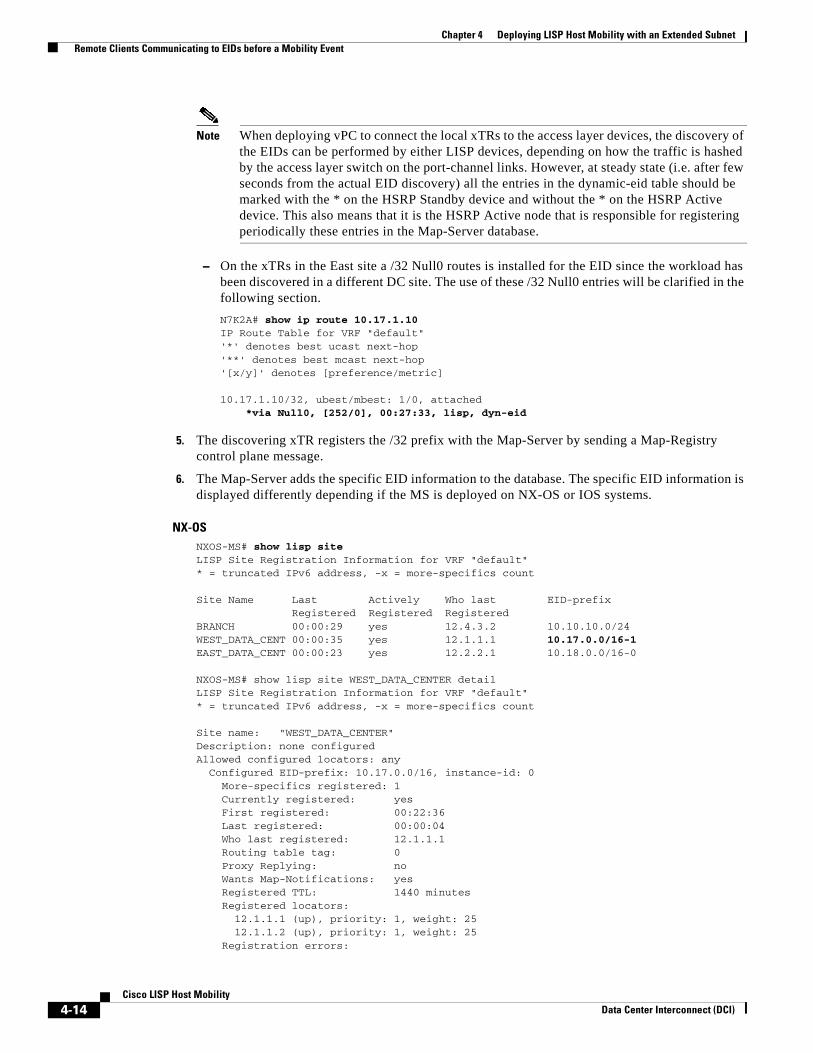
Note When deploying vPC to connect the local xTRs to the access layer devices, the discovery of the EIDs can be performed by either LISP devices, depending on how the traffic is hashed by the access layer switch on the port-channel links. However, at steady state (i.e. after few seconds from the actual EID discovery) all the entries in the dynamic-eid table should be marked with the * on the HSRP Standby device and without the * on the HSRP Active device. This also means that it is the HSRP Active node that is responsible for registering periodically these entries in the Map-Server database.
– On the xTRs in the East site a /32 Null0 routes is installed for the EID since the workload has been discovered in a different DC site. The use of these /32 Null0 entries will be clarified in the following section.N7K2A# show ip route 10.17.1.10IP Route Table for VRF "default"'*' denotes best ucast next-hop'**' denotes best mcast next-hop'[x/y]' denotes [preference/metric]
10.17.1.10/32, ubest/mbest: 1/0, attached *via Null0, [252/0], 00:27:33, lisp, dyn-eid
5. The discovering xTR registers the /32 prefix with the Map-Server by sending a Map-Registry control plane message.
6. The Map-Server adds the specific EID information to the database. The specific EID information is displayed differently depending if the MS is deployed on NX-OS or IOS systems.
NX-OSNXOS-MS# show lisp siteLISP Site Registration Information for VRF "default"* = truncated IPv6 address, -x = more-specifics count
Site Name Last Actively Who last EID-prefix Registered Registered RegisteredBRANCH 00:00:29 yes 12.4.3.2 10.10.10.0/24WEST_DATA_CENT 00:00:35 yes 12.1.1.1 10.17.0.0/16-1EAST_DATA_CENT 00:00:23 yes 12.2.2.1 10.18.0.0/16-0
NXOS-MS# show lisp site WEST_DATA_CENTER detail LISP Site Registration Information for VRF "default"* = truncated IPv6 address, -x = more-specifics count
Site name: "WEST_DATA_CENTER"Description: none configuredAllowed configured locators: any Configured EID-prefix: 10.17.0.0/16, instance-id: 0 More-specifics registered: 1 Currently registered: yes First registered: 00:22:36 Last registered: 00:00:04 Who last registered: 12.1.1.1 Routing table tag: 0 Proxy Replying: no Wants Map-Notifications: yes Registered TTL: 1440 minutes Registered locators: 12.1.1.1 (up), priority: 1, weight: 25 12.1.1.2 (up), priority: 1, weight: 25 Registration errors:
4-14Cisco LISP Host Mobility
Data Center Interconnect (DCI)
Chapter 4 Deploying LISP Host Mobility with an Extended Subnet Remote Clients Communicating to EIDs before a Mobility Event
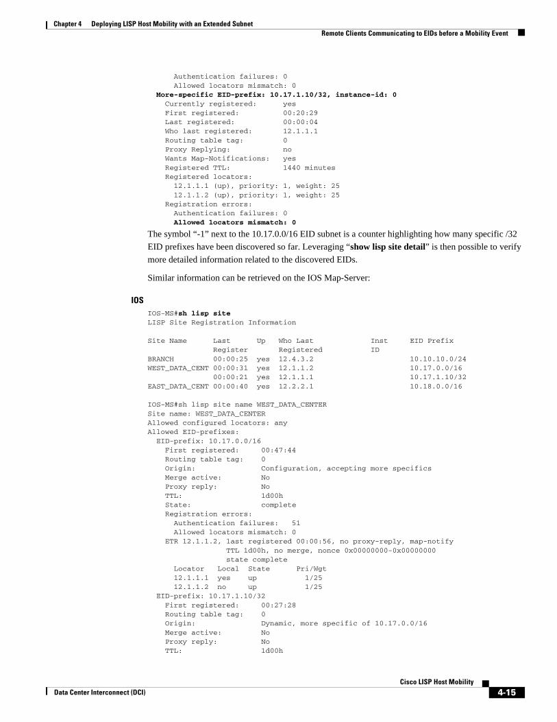
Authentication failures: 0 Allowed locators mismatch: 0 More-specific EID-prefix: 10.17.1.10/32, instance-id: 0 Currently registered: yes First registered: 00:20:29 Last registered: 00:00:04 Who last registered: 12.1.1.1 Routing table tag: 0 Proxy Replying: no Wants Map-Notifications: yes Registered TTL: 1440 minutes Registered locators: 12.1.1.1 (up), priority: 1, weight: 25 12.1.1.2 (up), priority: 1, weight: 25 Registration errors: Authentication failures: 0 Allowed locators mismatch: 0
The symbol “-1” next to the 10.17.0.0/16 EID subnet is a counter highlighting how many specific /32 EID prefixes have been discovered so far. Leveraging “show lisp site detail” is then possible to verify more detailed information related to the discovered EIDs.
Similar information can be retrieved on the IOS Map-Server:
IOSIOS-MS#sh lisp siteLISP Site Registration Information
Site Name Last Up Who Last Inst EID Prefix Register Registered ID BRANCH 00:00:25 yes 12.4.3.2 10.10.10.0/24WEST_DATA_CENT 00:00:31 yes 12.1.1.2 10.17.0.0/16 00:00:21 yes 12.1.1.1 10.17.1.10/32EAST_DATA_CENT 00:00:40 yes 12.2.2.1 10.18.0.0/16
IOS-MS#sh lisp site name WEST_DATA_CENTER Site name: WEST_DATA_CENTERAllowed configured locators: anyAllowed EID-prefixes: EID-prefix: 10.17.0.0/16 First registered: 00:47:44 Routing table tag: 0 Origin: Configuration, accepting more specifics Merge active: No Proxy reply: No TTL: 1d00h State: complete Registration errors: Authentication failures: 51 Allowed locators mismatch: 0 ETR 12.1.1.2, last registered 00:00:56, no proxy-reply, map-notify TTL 1d00h, no merge, nonce 0x00000000-0x00000000 state complete Locator Local State Pri/Wgt 12.1.1.1 yes up 1/25 12.1.1.2 no up 1/25 EID-prefix: 10.17.1.10/32 First registered: 00:27:28 Routing table tag: 0 Origin: Dynamic, more specific of 10.17.0.0/16 Merge active: No Proxy reply: No TTL: 1d00h
4-15Cisco LISP Host Mobility
Data Center Interconnect (DCI)

Chapter 4 Deploying LISP Host Mobility with an Extended Subnet Remote Clients Communicating to EIDs before a Mobility Event
State: complete Registration errors: Authentication failures: 0 Allowed locators mismatch: 0 ETR 12.1.1.1, last registered 00:00:56, no proxy-reply, map-notify TTL 1d00h, no merge, nonce 0x00000000-0x00000000 state complete Locator Local State Pri/Wgt 12.1.1.1 yes up 1/25 12.1.1.2 no up 1/25
At this point, a client situated in a remote location is able to successfully communicate to the EID. As shown in Figure 4-9, traffic destined to other less specific /16 prefix hosts is steered to the West DC based on ITR1 having that map-cache entry installed, while traffic destined to the more-specific /32 reaches the West DC based on that map-cache entry, as shown for ITR2. Notice that since the map-cache entries on the ITRs list both West DC RLOCs for each prefix, traffic inbound to the West DC will be load-balanced across both ETRs (the hashing value is calculated based on L3 and L4 flow parameters).
Figure 4-9 Successful Establishment of Client-Server Traffic Flows
The example above focuses only on the client-to-server traffic flows (prior to a host move). For return traffic concerns, two different scenarios are possible:
1. The branch subnets where the clients are deployed are injected in the core of the network. In this case, the DC xTRs will receive routing information about the branch subnets and as a consequence traffic will be natively forwarded (not LISP encapsulated).\
2. The branch subnets are EIDs as well (hence not injected in the routing protocol running in the core of the network). In this case, communication between the DC EIDs and the clients must happen through LISP. The mechanism is similar to the one discussed above, with the only difference that now the remote LISP devices become ETRs and the DC devices play the role of ITRs. In this case, the DC xTRs have to populate their map-cache tables to be able to encapsulate traffic to the remote locations (Figure 4-10).
4-16Cisco LISP Host Mobility
Data Center Interconnect (DCI)
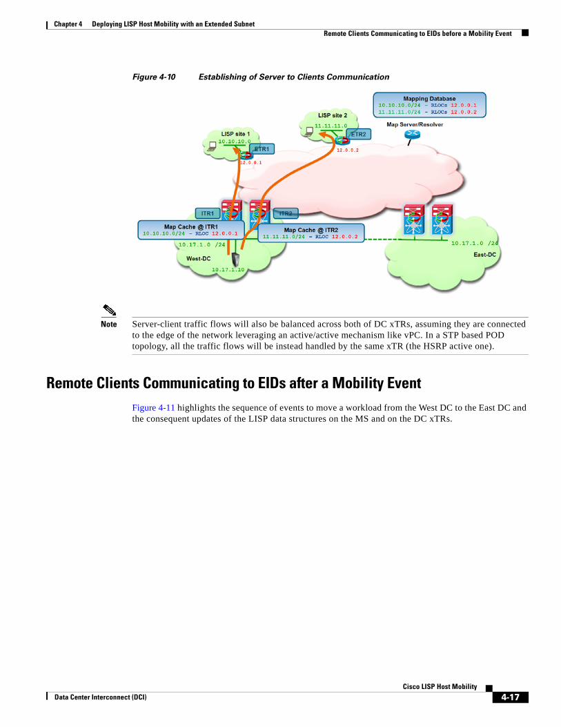
Chapter 4 Deploying LISP Host Mobility with an Extended Subnet Remote Clients Communicating to EIDs before a Mobility Event
Figure 4-10 Establishing of Server to Clients Communication
Note Server-client traffic flows will also be balanced across both of DC xTRs, assuming they are connected to the edge of the network leveraging an active/active mechanism like vPC. In a STP based POD topology, all the traffic flows will be instead handled by the same xTR (the HSRP active one).
Remote Clients Communicating to EIDs after a Mobility EventFigure 4-11 highlights the sequence of events to move a workload from the West DC to the East DC and the consequent updates of the LISP data structures on the MS and on the DC xTRs.
4-17Cisco LISP Host Mobility
Data Center Interconnect (DCI)
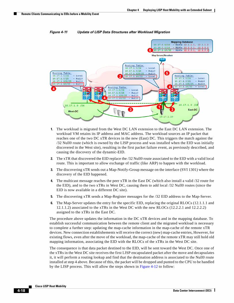
Chapter 4 Deploying LISP Host Mobility with an Extended Subnet Remote Clients Communicating to EIDs before a Mobility Event
Figure 4-11 Update of LISP Data Structures after Workload Migration
1. The workload is migrated from the West DC LAN extension to the East DC LAN extension. The workload VM retains its IP address and MAC address. The workload sources an IP packet that reaches one of the two DC xTR devices in the new (East) DC. This triggers the match against the /32 Null0 route (which is owned by the LISP process and was installed when the EID was initially discovered in the West site), resulting in the first packet failure event, as previously described, and causing the discovery of the dynamic-EID.
2. The xTR that discovered the EID replace the /32 Null0 route associated to the EID with a valid local route. This is important to allow exchange of traffic (like ARP) to happen with the workload.
3. The discovering xTR sends out a Map-Notify-Group message on the interface (SVI 1301) where the discovery of the EID happened.
4. The multicast message reaches the peer xTR in the East DC (which also install a valid /32 route for the EID), and to the two xTRs in West DC, causing them to add local /32 Null0 routes (since the EID is now available in a different DC site).
5. The discovering xTR sends a Map-Register messages for the /32 EID address to the Map-Server.
6. The Map-Server updates the entry for the specific EID, replacing the original RLOCs (12.1.1.1 and 12.1.1.2) associated to the xTRs in the West DC with the new RLOCs (12.2.2.1 and 12.2.2.2) assigned to the xTRs in the East DC.
The procedure above updates the information in the DC xTR devices and in the mapping database. To establish successful communication between the remote client and the migrated workload is necessary to complete a further step: updating the map-cache information in the map-cache of the remote xTR devices. New connection establishements will receive the correct (new) map-cache entries, However, for existing flows, even after the move of the workload, the map-cache of the remote xTR may still hold old mapping information, associating the EID with the RLOCs of the xTRs in the West DC site.
The consequence is that data packet destined to the EID, will be sent toward the West DC. Once one of the xTRs in the West DC site receives the first LISP encapsulated packet after the move and decapsulates it, it will perform a routing lookup and find that the destination address is associated to the Null0 route installed at step 4 above. Because of this, the packet will be dropped and punted to the CPU to be handled by the LISP process. This will allow the steps shown in Figure 4-12 to follow:
4-18Cisco LISP Host Mobility
Data Center Interconnect (DCI)
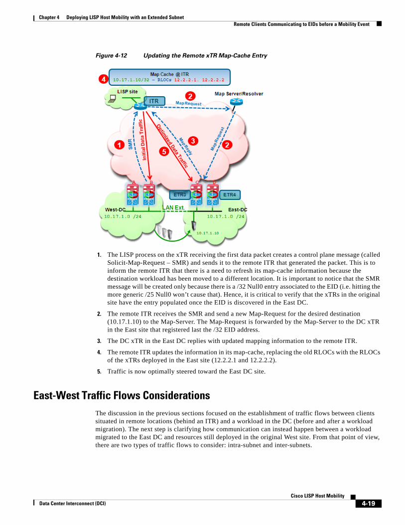
Chapter 4 Deploying LISP Host Mobility with an Extended Subnet Remote Clients Communicating to EIDs before a Mobility Event
Figure 4-12 Updating the Remote xTR Map-Cache Entry
1. The LISP process on the xTR receiving the first data packet creates a control plane message (called Solicit-Map-Request – SMR) and sends it to the remote ITR that generated the packet. This is to inform the remote ITR that there is a need to refresh its map-cache information because the destination workload has been moved to a different location. It is important to notice that the SMR message will be created only because there is a /32 Null0 entry associated to the EID (i.e. hitting the more generic /25 Null0 won’t cause that). Hence, it is critical to verify that the xTRs in the original site have the entry populated once the EID is discovered in the East DC.
2. The remote ITR receives the SMR and send a new Map-Request for the desired destination (10.17.1.10) to the Map-Server. The Map-Request is forwarded by the Map-Server to the DC xTR in the East site that registered last the /32 EID address.
3. The DC xTR in the East DC replies with updated mapping information to the remote ITR.
4. The remote ITR updates the information in its map-cache, replacing the old RLOCs with the RLOCs of the xTRs deployed in the East site (12.2.2.1 and 12.2.2.2).
5. Traffic is now optimally steered toward the East DC site.
East-West Traffic Flows ConsiderationsThe discussion in the previous sections focused on the establishment of traffic flows between clients situated in remote locations (behind an ITR) and a workload in the DC (before and after a workload migration). The next step is clarifying how communication can instead happen between a workload migrated to the East DC and resources still deployed in the original West site. From that point of view, there are two types of traffic flows to consider: intra-subnet and inter-subnets.
4-19Cisco LISP Host Mobility
Data Center Interconnect (DCI)

Chapter 4 Deploying LISP Host Mobility with an Extended Subnet Remote Clients Communicating to EIDs before a Mobility Event
Intra-Subnet Traffic Flows
The establishment of intra-subnet communication between two workloads part of the same IP subnet but connected in separate DC sites is shown in Figure 4-13.
Figure 4-13 Intra-Subnet Communication Between DC Sites
Since the IP subnet is extended between the West and East DC sites, the intra-subnet communication happens at L2 across that logical connection, without requiring any LISP functionality. This means that intra-subnet traffic flows can be established even before the EIDs are discovered by the LISP xTRs, and as a consequence these packets will never trigger a dynamic discovery event.
Inter-Subnets Traffic Flows
Let’s assume the desire is to establish inter-subnet communication between a host Z in subnet 10.17.2.0/24 in the West site and the previously discussed workload Y (10.17.1.10) that was migrated to the East DC. There are two scenarios to consider:
1. 10.17.2.0 is also a mobile subnet, which means it is extended between the DC sites. This scenario is highlighted in Figure 4-14.
4-20Cisco LISP Host Mobility
Data Center Interconnect (DCI)
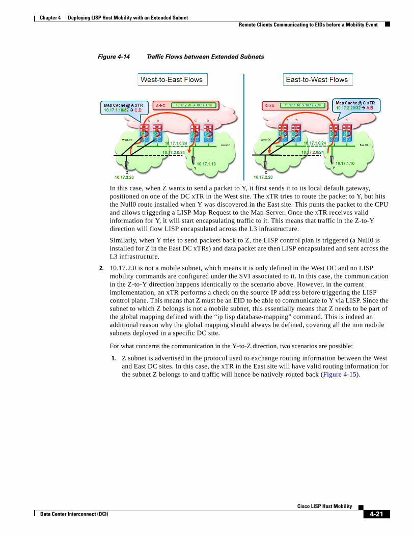
Chapter 4 Deploying LISP Host Mobility with an Extended Subnet Remote Clients Communicating to EIDs before a Mobility Event
Figure 4-14 Traffic Flows between Extended Subnets
In this case, when Z wants to send a packet to Y, it first sends it to its local default gateway, positioned on one of the DC xTR in the West site. The xTR tries to route the packet to Y, but hits the Null0 route installed when Y was discovered in the East site. This punts the packet to the CPU and allows triggering a LISP Map-Request to the Map-Server. Once the xTR receives valid information for Y, it will start encapsulating traffic to it. This means that traffic in the Z-to-Y direction will flow LISP encapsulated across the L3 infrastructure.
Similarly, when Y tries to send packets back to Z, the LISP control plan is triggered (a Null0 is installed for Z in the East DC xTRs) and data packet are then LISP encapsulated and sent across the L3 infrastructure.
2. 10.17.2.0 is not a mobile subnet, which means it is only defined in the West DC and no LISP mobility commands are configured under the SVI associated to it. In this case, the communication in the Z-to-Y direction happens identically to the scenario above. However, in the current implementation, an xTR performs a check on the source IP address before triggering the LISP control plane. This means that Z must be an EID to be able to communicate to Y via LISP. Since the subnet to which Z belongs is not a mobile subnet, this essentially means that Z needs to be part of the global mapping defined with the “ip lisp database-mapping” command. This is indeed an additional reason why the global mapping should always be defined, covering all the non mobile subnets deployed in a specific DC site.
For what concerns the communication in the Y-to-Z direction, two scenarios are possible:
1. Z subnet is advertised in the protocol used to exchange routing information between the West and East DC sites. In this case, the xTR in the East site will have valid routing information for the subnet Z belongs to and traffic will hence be natively routed back (Figure 4-15).
4-21Cisco LISP Host Mobility
Data Center Interconnect (DCI)

Chapter 4 Deploying LISP Host Mobility with an Extended Subnet Remote Clients Communicating to EIDs before a Mobility Event
Figure 4-15 Natively Routing Traffic from East to West DC
2. Z subnet is not injected in the routing protocol, because the goal is to make it only reachable via LISP encapsulation. In this case, when the packet from Y reaches the East xTR, a Map-Request for Z will be sent out and the reply from the Map-Server will be the global prefix covering Z subnet (10.17.0.0/16 in our configuration example), associated to the RLOCs of the DC xTRs belonging to the West DC site. Traffic will then be LISP encapsulated and sent toward that site across the L3 network infrastructure and eventually routed to Z (Figure 4-16).
Note /25 Null0 routes (10.17.2.0/25 and 10.17.2.128/25) are not installed in this case, since the subnet is not configured as mobile. This means that traffic can be successfully decapsulated and routed to Z.
Figure 4-16 LISP Encapsulating Traffic from East to West DC
4-22Cisco LISP Host Mobility
Data Center Interconnect (DCI)
Chapter 4 Deploying LISP Host Mobility with an Extended Subnet Summary
SummaryIn summary, the LISP Host Mobility solution with Extended Subnet provides the following key benefits:
• Automated move detection for workloads migrated between DC sites.
• Dynamic-EID discovery in multi-homed data centers.
• Inbound Path Optimization functionality, which provides automatic traffic redirection and avoids the traffic triangulation problem.
• Connections maintained across move: this makes this deployment suitable to solve "hot" migration use cases (like vMotion).
• No routing re-convergence.
• No DNS updates required, so the traffic optimization can happen transparently to the clients.
4-23Cisco LISP Host Mobility
Data Center Interconnect (DCI)

Chapter 4 Deploying LISP Host Mobility with an Extended Subnet Summary
4-24Cisco LISP Host Mobility
Data Center Interconnect (DCI)

Data Center Interconnect (DCI)
C H A P T E R 5
Deploying LISP Host Mobility Across SubnetsFigure 5-1 shows the Enterprise datacenter deployment topology with a West DC having the subnet 10.17.1.0/24 and an East DC having the subnet 10.18.1.0/24. The mobile subnet is 10.17.0.0/24 associated to VLAN 1301, which is locally defined in the West Data Center.
Figure 5-1 LISP Host Mobility across Subnets Topology
In the rest of this chapter, the specific site where the mobile subnet is natively defined may be called the “home site”, whereas the subnet itself can be referred to as the “home subnet”. The IP address space available in the East Data Center is instead completely independent from the one defined in the West DC. In the example above, the workloads that are moved away from the West DC site will land on a different 10.18.1.0/24 subnet locally defined in the East DC. The remote site is deployed with a Cisco IOS device hosting the 10.10.10.0/24 network. This section describes steps to configure these data center sites and remote IOS device sites as LISP sites with their corresponding EID spaces. This section also describes the required configuration to enable EIDs to move between data centers and highlights how client-server and inter-DC traffic flows can be established.
5-1Cisco LISP Host Mobility
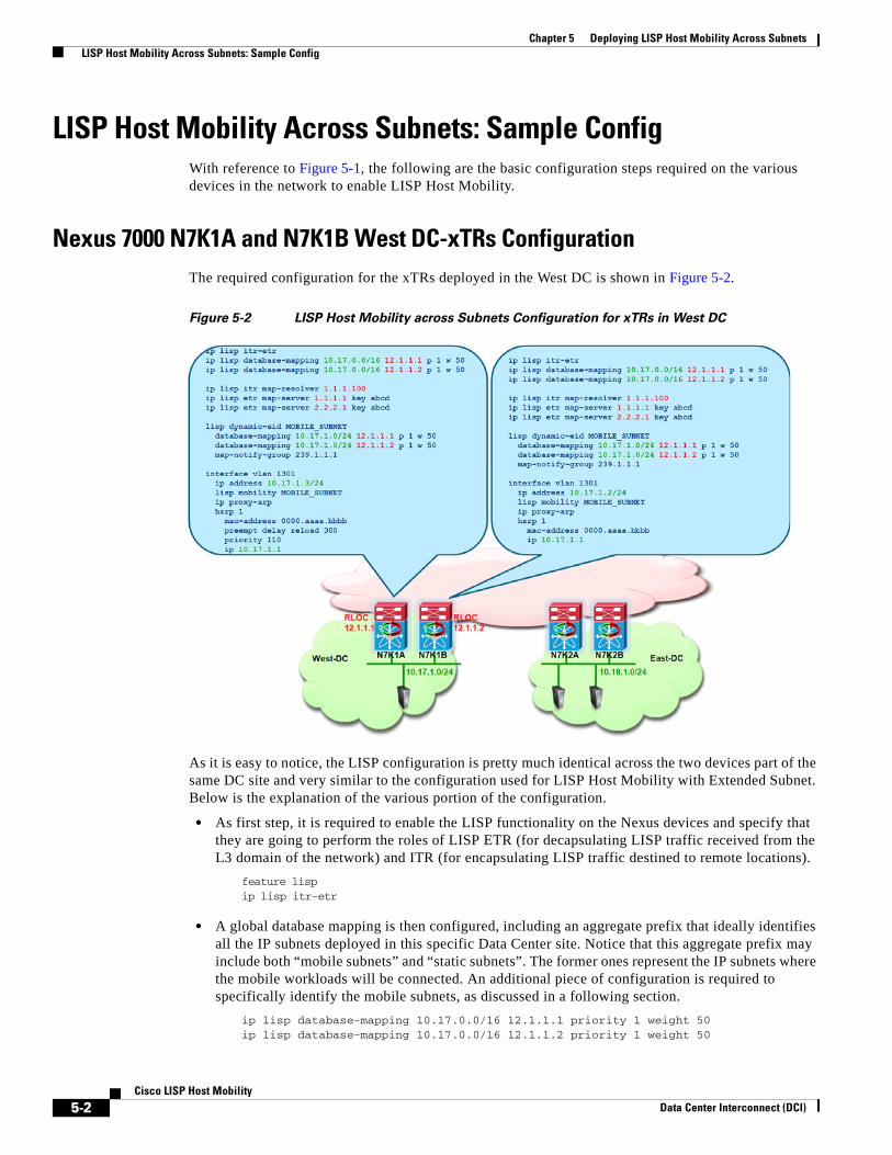
Chapter 5 Deploying LISP Host Mobility Across Subnets LISP Host Mobility Across Subnets: Sample Config
LISP Host Mobility Across Subnets: Sample ConfigWith reference to Figure 5-1, the following are the basic configuration steps required on the various devices in the network to enable LISP Host Mobility.
Nexus 7000 N7K1A and N7K1B West DC-xTRs ConfigurationThe required configuration for the xTRs deployed in the West DC is shown in Figure 5-2.
Figure 5-2 LISP Host Mobility across Subnets Configuration for xTRs in West DC
As it is easy to notice, the LISP configuration is pretty much identical across the two devices part of the same DC site and very similar to the configuration used for LISP Host Mobility with Extended Subnet. Below is the explanation of the various portion of the configuration.
• As first step, it is required to enable the LISP functionality on the Nexus devices and specify that they are going to perform the roles of LISP ETR (for decapsulating LISP traffic received from the L3 domain of the network) and ITR (for encapsulating LISP traffic destined to remote locations).
feature lisp ip lisp itr-etr
• A global database mapping is then configured, including an aggregate prefix that ideally identifies all the IP subnets deployed in this specific Data Center site. Notice that this aggregate prefix may include both “mobile subnets” and “static subnets”. The former ones represent the IP subnets where the mobile workloads will be connected. An additional piece of configuration is required to specifically identify the mobile subnets, as discussed in a following section.
ip lisp database-mapping 10.17.0.0/16 12.1.1.1 priority 1 weight 50ip lisp database-mapping 10.17.0.0/16 12.1.1.2 priority 1 weight 50
5-2Cisco LISP Host Mobility
Data Center Interconnect (DCI)
Chapter 5 Deploying LISP Host Mobility Across Subnets LISP Host Mobility Across Subnets: Sample Config
The mapping above associates the aggregate prefix 10.17.0.0/16 to two IP addresses, which are the RLOCs identifying each of the local DC xTR devices. The recommendation is to define a loopback interface on each device as RLOC, so that communication to that IP address will remain successful as long as a valid L3 path connects the xTR to the L3 domain of the network.
Notice also how a priority and a weight can be associated to each mapping statement: these values can be tuned to influence the inbound traffic, preferring for example the path through a specific xTR. In the configuration above the values are identical to ensure that inbound traffic can be load-balanced across both DC xTRs.
Note The definition of the global database-mapping statements are particularly important to enable communication between a remote client and mobile workloads connected to the mobile subnet in the home site, as it will be explained in detail in the “East-West Traffic Flows Considerations” section on page 4-19.
• The next step consists of defining the IP addresses of the Map-Servers and Map-Resolvers. ip lisp itr map-resolver 1.1.1.100ip lisp etr map-server 1.1.1.1 key abcd ip lisp etr map-server 2.2.2.1 key abcd
As already mentioned, in a typical Enterprise deployment, two devices will perform the roles of MS/MR and work in a complete stateless fashion. As a consequence, on the xTRs we need to specify the IP addresses of the two Map-Servers (so that each xTR can register with both MS the EID prefixes) and the Anycast IP address of the Map-Resolver (so that the Map-Requests will be received by the MR that is closer from a routing perspective).
• A dynamic mapping is then required to identify the IP subnets to which the mobile workloads belong.
lisp dynamic-eid MOBILE_SUBNET database-mapping 10.17.1.0/24 12.1.1.1 priority 1 weight 25 database-mapping 10.17.1.0/24 12.1.1.2 priority 1 weight 25 map-notify-group 239.1.1.1
In this example, the mobile subnet is a /24 prefix, which is associated to the same two RLOCs previously used for the global mapping. Priorities and weights are kept the same also in this case, to achieve inbound load balancing for traffic destined to the mobile subnet. A multicast address (named “map-notify-group”) must also be associated to the dynamic-eid mapping. Its use will be clarified in the following sections of the document.
Some additional considerations around the length of the network prefix specified in the dynamic-eid mapping:
– If multiple mobile subnets are configured, it is possible to define a different “lisp dynamic-eid” construct for each subnet or to use a coarser prefix. The multicast address of the map-notify-group can be the same across multiple constructs.
– The mask associated to the dynamic-eid prefix should always be more specific that the one used in the global mapping statements.
– Differently than in LISP with Extended Subnet mode, there is no specific relationship between the length of the mask associated to the dynamic-eid prefix and the network mask of the interface where LISP mobility is enabled. It is anyway common practice to match the two values, as shown in the example here under discussion.
5-3Cisco LISP Host Mobility
Data Center Interconnect (DCI)
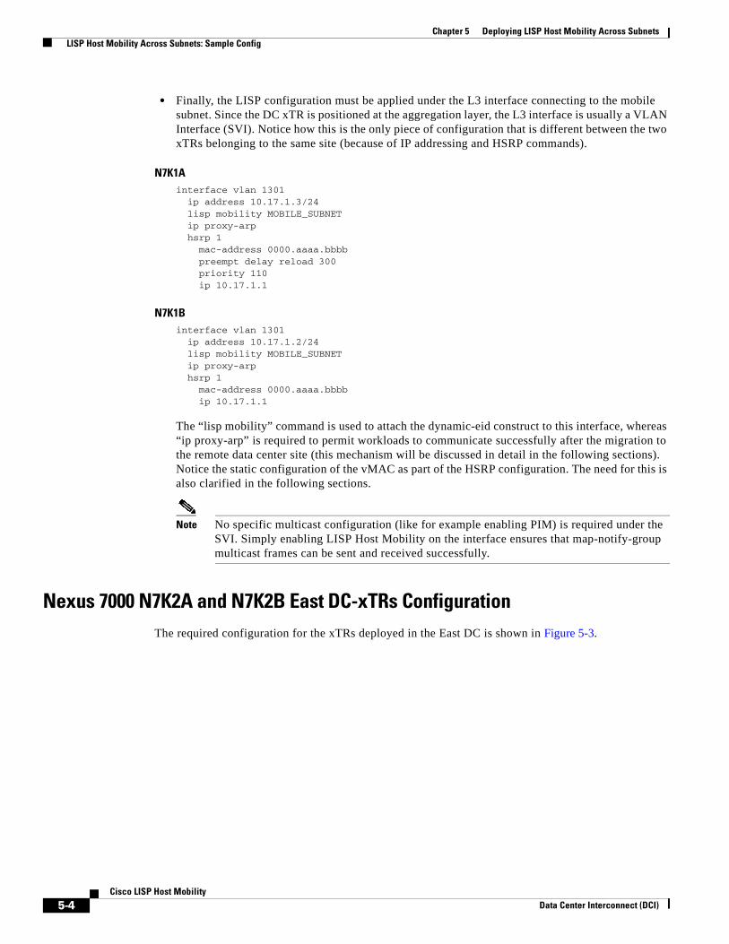
Chapter 5 Deploying LISP Host Mobility Across Subnets LISP Host Mobility Across Subnets: Sample Config
• Finally, the LISP configuration must be applied under the L3 interface connecting to the mobile subnet. Since the DC xTR is positioned at the aggregation layer, the L3 interface is usually a VLAN Interface (SVI). Notice how this is the only piece of configuration that is different between the two xTRs belonging to the same site (because of IP addressing and HSRP commands).
N7K1Ainterface vlan 1301 ip address 10.17.1.3/24 lisp mobility MOBILE_SUBNET ip proxy-arp hsrp 1 mac-address 0000.aaaa.bbbb preempt delay reload 300 priority 110 ip 10.17.1.1
N7K1Binterface vlan 1301 ip address 10.17.1.2/24 lisp mobility MOBILE_SUBNET ip proxy-arp hsrp 1 mac-address 0000.aaaa.bbbb ip 10.17.1.1
The “lisp mobility” command is used to attach the dynamic-eid construct to this interface, whereas “ip proxy-arp” is required to permit workloads to communicate successfully after the migration to the remote data center site (this mechanism will be discussed in detail in the following sections). Notice the static configuration of the vMAC as part of the HSRP configuration. The need for this is also clarified in the following sections.
Note No specific multicast configuration (like for example enabling PIM) is required under the SVI. Simply enabling LISP Host Mobility on the interface ensures that map-notify-group multicast frames can be sent and received successfully.
Nexus 7000 N7K2A and N7K2B East DC-xTRs ConfigurationThe required configuration for the xTRs deployed in the East DC is shown in Figure 5-3.
5-4Cisco LISP Host Mobility
Data Center Interconnect (DCI)

Chapter 5 Deploying LISP Host Mobility Across Subnets LISP Host Mobility Across Subnets: Sample Config
Figure 5-3 LISP Host Mobility across Subnets Configuration for xTRs in East DC
The explanation of the various part of the configuration has been already done in the previous section. The few things to notice when comparing it with the West DC xTRs are the following:
• The global mapping must be different from the one configured on the West DC xTRs. Again, the assumption here is that the IP subnets deployed in the East site can be aggregated by a unique IP prefix (10.18.0.0/16 in this case). Also, the RLOC associated to the global prefixes are now identifying the xTR devices in the East DC site.
• The prefix in the dynamic-eid mapping identifying the mobile subnet must be identical to the one defined on the West xTRs, since it identifies the IP subnet where the mobile workloads are connected. This is the reason why 10.17.1.0/24 is specified also on the xTRs in the East DC. However, the RLOCs associated to the mobile subnet are now identifying the xTRs in the East site.
Note The same considerations would apply if we wanted to enable migration of workloads connected to the East DC as home site (for example belonging to the IP subnet 10.18.1.0/24).
• Despite the fact that mobile workloads from the 10.17.1.0/24 subnet can be moved to the East DC site and retain their original IP addresses, there is no need to define an SVI belonging to 10.17.1.0/24 in the East DC. This is a consequence of the true IP Mobility functionality across L3 network domains enabled by LISP.
• The map-notify-group associated to the dynamic-eid mapping must be different to the one configured for the xTRs in the West site. This is because, differently from what discussed for LISP Host Mobility with Extended Subnet Mode, the multicast communication on this group must be limited between the LISP xTR devices connected to the same local DC site.
5-5Cisco LISP Host Mobility
Data Center Interconnect (DCI)

Chapter 5 Deploying LISP Host Mobility Across Subnets LISP Host Mobility Across Subnets: Sample Config
• Notice how the HSRP group 2 configured on the LISP xTRs in the East DC is different from the one (HSRP group 1) used in the West DC site. In this case, it is recommended to statically configure the same HSRP vMAC (000.aaaa.bbbb in the example above), to ensure that a migrated workload can consistently send traffic to the default gateway. However, since the deployment of LISP Host Mobility Across Subnets is currently positioned for “cold migration” scenarios, it is likely that the ARP cache of the migrated workload is initially empty. In this case, just having proxy ARP enabled on the SVI 1301 would ensure that the workload can successfully resolve the MAC address of the localized gateway, making the static vMAC configuration optional.
Note To cover all the scenarios, it is recommended to have a consistent vMAC across different DC sites. The easiest way to achieve that is by configuring the same HSRP group everywhere, as discussed for the LIPS Mobility with Extended Subnets scenario.
Remote Site Cisco IOS-xTR Configuration
The configuration of the branch xTR is shown in Figure 5-4.
Figure 5-4 Remote xTR IOS Configuration
Compared to the DC xTR, the configuration for the remote xTR is very simple, since there are usually no Host Mobility requirements for the EIDs belonging to remote locations. The explanation of the different commands is almost self-explanatory. Notice how IOS requires that the LISP configuration is added under a “router lisp” construct, in a similar fashion on how a routing protocol is usually enabled.
• Define the EID space where the clients that will communicate to the DC workloads are deployed.database-mapping 10.10.10.0/24 12.0.0.1 priority 1 weight 100
5-6Cisco LISP Host Mobility
Data Center Interconnect (DCI)
Chapter 5 Deploying LISP Host Mobility Across Subnets LISP Host Mobility Across Subnets: Sample Config
The RLOC address associated to the EID prefix may be a loopback address (as recommended for the DC xTR devices) or, in scenarios where the remote xTR connects to separate SP connections, the IP address of the physical links toward the providers may be used as RLOCs. This last option is usually recommended when it is desirable to tune the priority and weight parameters associated to each RLOC, to influence the inbound traffic policies.
• Configure the Map-Servers and the Map-Resolver Anycast address.ipv4 itr map-resolver 1.1.1.100ipv4 etr map-server 1.1.1.1 key abcdipv4 etr map-server 2.2.2.1 key abcd
Note When deploying redundant xTR devices at the remote locations, multiple RLOCs are usually associated to the same EID subnet, similarly to what previously shown for the DC xTRs.
• Enable the ITR and ETR functionalities on the device.ipv4 itripv4 etr
NX-OS Map-Server and Map-Resolver ConfigurationConsiderations around the recommended MS/MR deployment options in LISP Enterprise deployments have been already discussed in the previous “Map-Server and Map-Resolver Deployment Considerations” section on page 3-6. Figure 5-5 shows the configuration required when deploying the MS/MR on NX-OS platforms also configured as LISP DC xTR devices.
5-7Cisco LISP Host Mobility
Data Center Interconnect (DCI)

Chapter 5 Deploying LISP Host Mobility Across Subnets LISP Host Mobility Across Subnets: Sample Config
Figure 5-5 NX-OS and IOS MS/MR Configurations
Notice how the configuration on the two MS/MR devices is basically identical, with the only exception of the IP address used as Map-Server identifier. The different parts of the NX-OS configuration are explained below (the equivalent IOS configuration is also shown, in scenarios where dedicated standalone MS/MR are deployed).
Step 1 Enable the MS and MR functionalities on the device.
NX-OS
feature lisp
ip lisp map-resolver
ip lisp map-server
IOS
router lisp
ipv4 map-server
ipv4 map-resolver
Step 2 Define the Loopback interfaces used as IP addresses for the Map-Resolver and Map-Server functions.
NX-OS
interface loopback0
description Map-Resolver IP Address
ip address 1.1.1.100/32
!
interface loopback1
description Map-Server IP Address
5-8Cisco LISP Host Mobility
Data Center Interconnect (DCI)

Chapter 5 Deploying LISP Host Mobility Across Subnets LISP Host Mobility Across Subnets: Sample Config
ip address 1.1.1.1/32
IOS
interface loopback0
description Map-Resolver IP Address
ip address 1.1.1.100 255.255.255.255
!
interface loopback1
description Map-Server IP Address
ip address 1.1.1.1 255.255.255.255
Both Map-Resolvers in Figure 5-5 are configured with the same IP address (Anycast IP address), so that Map-Requests originated from LISP ITR devices can be received on the MR device that is “closer” from a routing table point of view. A unique IP address is instead leveraged for the Map-Server, because the LISP ETRs must register their EID subnets with both standalone Map-Servers.
Step 3 Configure the remote branch site.
NX-OSlisp site BRANCH eid-prefix 10.10.10.0/24 authentication-key 0 abcd
IOSrouter lisp site BRANCH authentication-key abcd eid-prefix 10.10.10.0/24
Step 4 Configure the West and East Data Center sites.
NX-OSlisp site WEST_DATA_CENTER eid-prefix 10.17.0.0/16 accept-more-specifics authentication-key 0 abcd! lisp site EAST_DATA_CENTER eid-prefix 10.18.0.0/16 accept-more-specifics authentication-key 0 abcd
IOSsite WEST_DATA_CENTER authentication-key abcd eid-prefix 10.17.0.0/16 accept-more-specifics ! site EAST_DATA_CENTER authentication-key abcd eid-prefix 10.18.0.0/16 accept-more-specifics
It is important to notice the “accept-more-specifics” keyword associated to the DC EID prefix. This needs to be configured for the sites where LISP Host Mobility is enabled, since specific /32 prefixes part of the larger aggregate prefix will be registered by the DC xTRs. The reasoning behind this behavior will be clarified in detail in the following section.
5-9Cisco LISP Host Mobility
Data Center Interconnect (DCI)
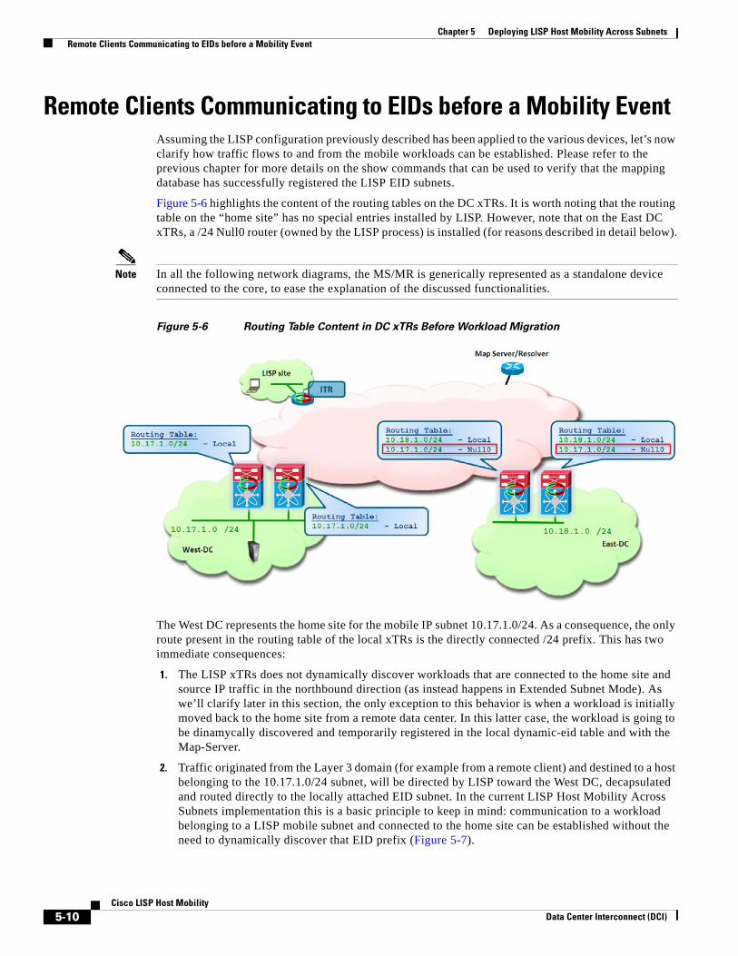
Chapter 5 Deploying LISP Host Mobility Across Subnets Remote Clients Communicating to EIDs before a Mobility Event
Remote Clients Communicating to EIDs before a Mobility Event Assuming the LISP configuration previously described has been applied to the various devices, let’s now clarify how traffic flows to and from the mobile workloads can be established. Please refer to the previous chapter for more details on the show commands that can be used to verify that the mapping database has successfully registered the LISP EID subnets.
Figure 5-6 highlights the content of the routing tables on the DC xTRs. It is worth noting that the routing table on the “home site” has no special entries installed by LISP. However, note that on the East DC xTRs, a /24 Null0 router (owned by the LISP process) is installed (for reasons described in detail below).
Note In all the following network diagrams, the MS/MR is generically represented as a standalone device connected to the core, to ease the explanation of the discussed functionalities.
Figure 5-6 Routing Table Content in DC xTRs Before Workload Migration
The West DC represents the home site for the mobile IP subnet 10.17.1.0/24. As a consequence, the only route present in the routing table of the local xTRs is the directly connected /24 prefix. This has two immediate consequences:
1. The LISP xTRs does not dynamically discover workloads that are connected to the home site and source IP traffic in the northbound direction (as instead happens in Extended Subnet Mode). As we’ll clarify later in this section, the only exception to this behavior is when a workload is initially moved back to the home site from a remote data center. In this latter case, the workload is going to be dinamycally discovered and temporarily registered in the local dynamic-eid table and with the Map-Server.
2. Traffic originated from the Layer 3 domain (for example from a remote client) and destined to a host belonging to the 10.17.1.0/24 subnet, will be directed by LISP toward the West DC, decapsulated and routed directly to the locally attached EID subnet. In the current LISP Host Mobility Across Subnets implementation this is a basic principle to keep in mind: communication to a workload belonging to a LISP mobile subnet and connected to the home site can be established without the need to dynamically discover that EID prefix (Figure 5-7).
5-10Cisco LISP Host Mobility
Data Center Interconnect (DCI)
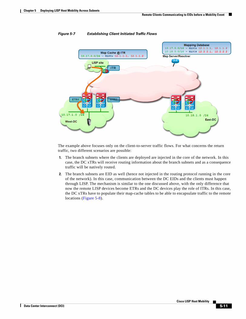
Chapter 5 Deploying LISP Host Mobility Across Subnets Remote Clients Communicating to EIDs before a Mobility Event
Figure 5-7 Establishing Client Initiated Traffic Flows
The example above focuses only on the client-to-server traffic flows. For what concerns the return traffic, two different scenarios are possible:
1. The branch subnets where the clients are deployed are injected in the core of the network. In this case, the DC xTRs will receive routing information about the branch subnets and as a consequence traffic will be natively routed.
2. The branch subnets are EID as well (hence not injected in the routing protocol running in the core of the network). In this case, communication between the DC EIDs and the clients must happen through LISP. The mechanism is similar to the one discussed above, with the only difference that now the remote LISP devices become ETRs and the DC devices play the role of ITRs. In this case, the DC xTRs have to populate their map-cache tables to be able to encapsulate traffic to the remote locations (Figure 5-8).
5-11Cisco LISP Host Mobility
Data Center Interconnect (DCI)
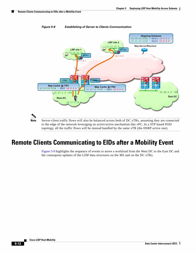
Chapter 5 Deploying LISP Host Mobility Across Subnets Remote Clients Communicating to EIDs after a Mobility Event
Figure 5-8 Establishing of Server to Clients Communication
Note Server-client traffic flows will also be balanced across both of DC xTRs, assuming they are connected to the edge of the network leveraging an active/active mechanism like vPC. In a STP based POD topology, all the traffic flows will be instead handled by the same xTR (the HSRP active one).
Remote Clients Communicating to EIDs after a Mobility Event Figure 5-9 highlights the sequence of events to move a workload from the West DC to the East DC and the consequent updates of the LISP data structures on the MS and on the DC xTRs.
5-12Cisco LISP Host Mobility
Data Center Interconnect (DCI)

Chapter 5 Deploying LISP Host Mobility Across Subnets Remote Clients Communicating to EIDs after a Mobility Event
Figure 5-9 Update of LISP Data Structures after Workload Migration
1. The workload is migrated from the West DC (with subnet 10.17.1.0/24) to the East DC (with subnect 10.18.1.0/24). The workload VM retains its IP address and MAC address, and sources an IP packet that reaches one of the two DC xTR devices. This triggers an “URPF-like” failure event, since the packet is received on a local SVI belonging to the 10.18.1.0/24 subnet and the source of the packet is from the 10.17.1.0/24 subnet. The result of the check failure is that the packet is punted to the CPU, causing the dynamic discovery of the EID.
Note IP packets sourced by the migrated workload are steered toward the local gateway because of the proxy-ARP function (if the ARP cache of the workload is empty after the move is completed) or because a consistent vMAC/VIP pair is locally provided (in case the assumption is that the ARP cache of the workload after the migration retains the information populated while in the original home site).
2. The xTR that discovered the EID installs in routing table a local /32 route associated to the EID. This is important to allow exchange of traffic (like ARP) to happen with the workload, since that traffic would normally be prevented by the /24 Null0 entry.
3. The discovering xTR sends out a Map-Notify-Group message on the interface (SVI 1301) where the discovery of the EID happened.
4. The multicast message reaches the peer xTR in the East DC side, which also install a valid /32 route for the EID.
5. The discovering xTR sends a Map-Register messages for the /32 EID address to the Map-Server.
6. The Map-Server adds to the database the entry for the specific EID, associated to the RLOCs (12.2.2.1 and 12.2.2.2) assigned to the xTRs in the East DC.
7. The Map-Server sends a Map-Notify message to the last xTR in the West DC that registered the 10.17.0.0/16 prefix. This message is to notify the xTR that a specific workload belonging to that subnet has just been discovered in a remote DC site.
5-13Cisco LISP Host Mobility
Data Center Interconnect (DCI)
Chapter 5 Deploying LISP Host Mobility Across Subnets Remote Clients Communicating to EIDs after a Mobility Event
8. The xTR in the West DC receives the Map-Notify message from the Map-Server and adds to the routing table a /32 Null0 route associated to the 10.17.1.10 EID.
9. The West DC xTR also notifies its peer by leveraging a site local Map-notify message.
10. The West DC peer xTR also installs in the routing table the /32 Null0 route associated to the 10.17.1.10 EID.
Note Once an EID is discovered in the remote data center site, a periodic liveliness check is perfomed by the xTR that discovered it. The check is performed by pinging the EID every 60 seconds. If three consecutive PINGs are not responded to, the LISP xTR removes the EID from its dynamic EID table and stops registering it with the Map-Server. This is done to handle scenarios where EIDs are silently disconnected from the network.
The process above allows updating the information in the DC xTR devices and in the mapping database. To establish successful communication between the remote client and the migrated workload it is necessary to complete a further step: updating the map-cache information in the map-cache of the remote xTR devices. Even after the move of the workload, the map-cache of the remote xTR may still have old mapping information, associating EIDs part of the global /16 prefix with the RLOCs of the xTRs in the West site. This is the case for example if communication between the client and the workload was started before the move.
The consequence is that data packet destined to the migrated EID, will be sent toward the West DC. Once one of the xTRs in that site receives it and decapsulates the first packet, it will perform a routing lookup and find that the destination address is associated to the Null0 route installed at steps 8 and 10 above. Because of this, the packet will be dropped and punted to the CPU to be handled by the LISP process. This will allow the steps shown in Figure 5-10 to happen:
5-14Cisco LISP Host Mobility
Data Center Interconnect (DCI)

Chapter 5 Deploying LISP Host Mobility Across Subnets Remote Clients Communicating to EIDs after a Mobility Event
Figure 5-10 Updating the Remote xTR Map-Cache Entry
1. The LISP process on the xTR receiving the first data packet creates a control plane message (called Solicit-Map-Request – SMR) and sends it to the remote ITR that generated the packet. This is to inform the remote ITR that there is a need to refresh its map-cache information because the destination workload has been moved to a different location. It is important to notice that for the SMR message to be created it is mandatory to have a /32 Null0 entry associated to the EID, since without that traffic will be natively routed to the 10.17.1.0/24 home subnet and subsequently dropped. Hence, it is critical to verify that the xTRs in the original site have the entry populated once the EID is discovered in the East DC.
2. The remote ITR receives the SMR and send a new Map-Request for the desired destination (10.17.1.10) to the Map-Server. The Map-Request is forwarded by the Map-Server to the DC xTR in the East site that registered last the /32 EID address.
3. The DC xTR in the East DC replies with updated mapping information to the remote ITR.
4. The remote ITR updates the information in its map-cache, adding the specific /32 EID address associated to the xTRs deployed in the East site (12.2.2.1 and 12.2.2.2).
5. Traffic is now optimally steered toward the East DC site.
Per Figure 5-9, once a workload is discovered in the remote DC site, a corresponding /32 Null0 route is added to both LISP xTRs in the home site (West DC is the home site for 10.17.1.0/24 in our example). The presence of this route forces the dynamic discovery of the EID once it returns to the home site. The sequence of events happening in this case is described in Figure 5-11.
5-15Cisco LISP Host Mobility
Data Center Interconnect (DCI)
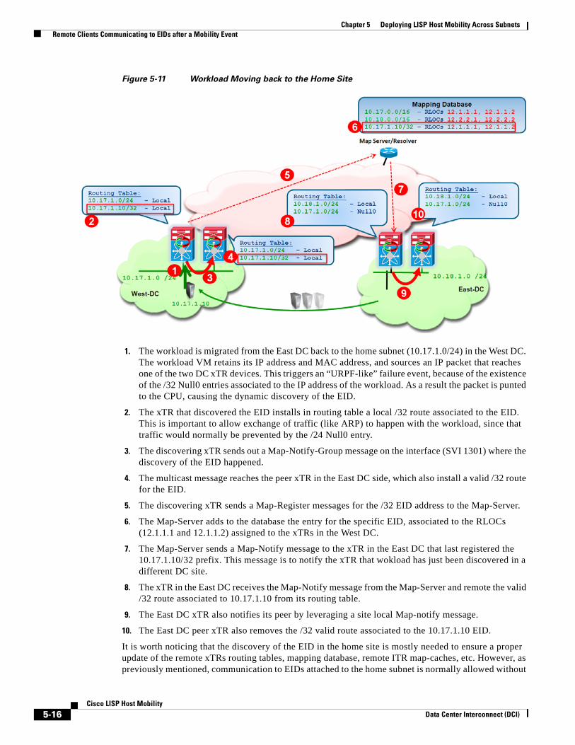
Chapter 5 Deploying LISP Host Mobility Across Subnets Remote Clients Communicating to EIDs after a Mobility Event
Figure 5-11 Workload Moving back to the Home Site
1. The workload is migrated from the East DC back to the home subnet (10.17.1.0/24) in the West DC. The workload VM retains its IP address and MAC address, and sources an IP packet that reaches one of the two DC xTR devices. This triggers an “URPF-like” failure event, because of the existence of the /32 Null0 entries associated to the IP address of the workload. As a result the packet is punted to the CPU, causing the dynamic discovery of the EID.
2. The xTR that discovered the EID installs in routing table a local /32 route associated to the EID. This is important to allow exchange of traffic (like ARP) to happen with the workload, since that traffic would normally be prevented by the /24 Null0 entry.
3. The discovering xTR sends out a Map-Notify-Group message on the interface (SVI 1301) where the discovery of the EID happened.
4. The multicast message reaches the peer xTR in the East DC side, which also install a valid /32 route for the EID.
5. The discovering xTR sends a Map-Register messages for the /32 EID address to the Map-Server.
6. The Map-Server adds to the database the entry for the specific EID, associated to the RLOCs (12.1.1.1 and 12.1.1.2) assigned to the xTRs in the West DC.
7. The Map-Server sends a Map-Notify message to the xTR in the East DC that last registered the 10.17.1.10/32 prefix. This message is to notify the xTR that wokload has just been discovered in a different DC site.
8. The xTR in the East DC receives the Map-Notify message from the Map-Server and remote the valid /32 route associated to 10.17.1.10 from its routing table.
9. The East DC xTR also notifies its peer by leveraging a site local Map-notify message.
10. The East DC peer xTR also removes the /32 valid route associated to the 10.17.1.10 EID.
It is worth noticing that the discovery of the EID in the home site is mostly needed to ensure a proper update of the remote xTRs routing tables, mapping database, remote ITR map-caches, etc. However, as previously mentioned, communication to EIDs attached to the home subnet is normally allowed without
5-16Cisco LISP Host Mobility
Data Center Interconnect (DCI)

Chapter 5 Deploying LISP Host Mobility Across Subnets East-West Traffic Flows Considerations
requiring installing host routes in the routing table of the local xTRs. As a consequence, the existence of the host routes highlighted in Figure 5-11 is only temporary: a timer (3 minutes) is started after the dynamic discovery of the EID and at its expiration, the EID 10.17.1.10 is removed from the dynamic-table of the local xTRs, the corresponding host route from their routing tables and the IP address is also removed from the mapping database. New ITRs needing to send traffic to that EID would be allowed to do so by following the global 10.17.0.0/16 prefix (as initially highlighted in Figure 5-7).
East-West Traffic Flows ConsiderationsThe discussion in the previous sections focused on the establishment of traffic flows between clients situated in remote locations (behind an ITR) and a workload in the DC (before and after a workload migration). The next step is clarifying how communication can instead happen between a workload migrated to the East DC and resources still deployed in the original West site. From that point of view, there are two types of traffic flows to consider: intra-subnet and inter-subnets.
Intra-Subnet Traffic FlowsThe establishment of intra-subnet communication between two workloads part of the same IP subnet but connected in separate DC sites is shown in Figure 5-12, respectively for the West-to-East and East-to-West directions.
Figure 5-12 Intra-Subnet Communication between DC Sites
• West to East: the initial assumption is that the host X does not have any information for Y in its ARP table, so that it will send out a new ARP request for it. This will allow proxy-ARP enabled on the SVI 1301 to provide the vMAC of the default gateway as response. Notice that for this to happen, it is critical that the xTRs in the West DC have the 10.17.1.10/32 route associated to Null0 (otherwise proxy-ARP would not reply because the 10.17.10/24 subnet is locally connected to the SVI).
The above assumption is surely valid if no communication was established between the two machines before the migration of Y to the East site. In cases where X and Y started communicating in the West DC site, the specific ARP entry associated to Y will be removed from X’s ARP cache by a Gratuitous ARP generated by the West DC xTR when it receives the Map-Notify message from the Map-Server when Y is discovered in the East site (step 7 of the process shown in Figure 5-9).
5-17Cisco LISP Host Mobility
Data Center Interconnect (DCI)
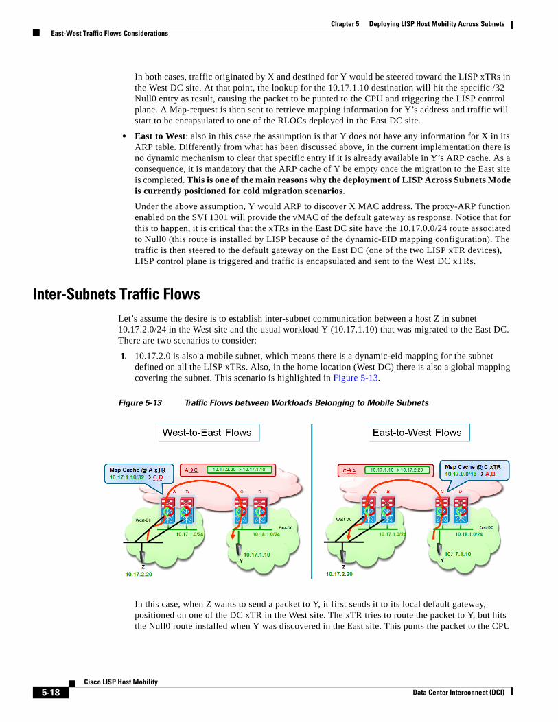
Chapter 5 Deploying LISP Host Mobility Across Subnets East-West Traffic Flows Considerations
In both cases, traffic originated by X and destined for Y would be steered toward the LISP xTRs in the West DC site. At that point, the lookup for the 10.17.1.10 destination will hit the specific /32 Null0 entry as result, causing the packet to be punted to the CPU and triggering the LISP control plane. A Map-request is then sent to retrieve mapping information for Y’s address and traffic will start to be encapsulated to one of the RLOCs deployed in the East DC site.
• East to West: also in this case the assumption is that Y does not have any information for X in its ARP table. Differently from what has been discussed above, in the current implementation there is no dynamic mechanism to clear that specific entry if it is already available in Y’s ARP cache. As a consequence, it is mandatory that the ARP cache of Y be empty once the migration to the East site is completed. This is one of the main reasons why the deployment of LISP Across Subnets Mode is currently positioned for cold migration scenarios.
Under the above assumption, Y would ARP to discover X MAC address. The proxy-ARP function enabled on the SVI 1301 will provide the vMAC of the default gateway as response. Notice that for this to happen, it is critical that the xTRs in the East DC site have the 10.17.0.0/24 route associated to Null0 (this route is installed by LISP because of the dynamic-EID mapping configuration). The traffic is then steered to the default gateway on the East DC (one of the two LISP xTR devices), LISP control plane is triggered and traffic is encapsulated and sent to the West DC xTRs.
Inter-Subnets Traffic FlowsLet’s assume the desire is to establish inter-subnet communication between a host Z in subnet 10.17.2.0/24 in the West site and the usual workload Y (10.17.1.10) that was migrated to the East DC. There are two scenarios to consider:
1. 10.17.2.0 is also a mobile subnet, which means there is a dynamic-eid mapping for the subnet defined on all the LISP xTRs. Also, in the home location (West DC) there is also a global mapping covering the subnet. This scenario is highlighted in Figure 5-13.
Figure 5-13 Traffic Flows between Workloads Belonging to Mobile Subnets
In this case, when Z wants to send a packet to Y, it first sends it to its local default gateway, positioned on one of the DC xTR in the West site. The xTR tries to route the packet to Y, but hits the Null0 route installed when Y was discovered in the East site. This punts the packet to the CPU
5-18Cisco LISP Host Mobility
Data Center Interconnect (DCI)

Chapter 5 Deploying LISP Host Mobility Across Subnets East-West Traffic Flows Considerations
and allows triggering a LISP Map-Request to the Map-Server. Once the xTR receives valid information for Y, it will start encapsulating traffic to it. This means that traffic in the Z-to-Y direction will flow using LISP encapsulation across the L3 infrastructure.
Similarly, when Y tries to send packets back to Z, the LISP control plan is triggered (a /24 Null0 is installed for the subnet of Z in the East DC xTRs, since it is mobile) and data packet are then LISP encapsulated and sent across the L3 infrastructure.
2. 10.17.2.0 is not a mobile subnet, which means no LISP mobility commands are configured under the SVI associated to it.
In this case, the communication in the Z-to-Y direction happens identically to the scenario above. However, in the current implementation, an xTR performs a check on the source IP address before triggering the LISP control plane. This means that Z must be an EID to be able to communicate to Y via LISP. Since the subnet to which Z belongs is not a mobile subnet, this essentially means that Z needs to be part of the global mapping defined with the “ip lisp database-mapping” command. This is indeed an additional reason why the global mapping should always be defined, covering all the non mobile subnets deployed in a specific DC site.
For what concerns the communication in the Y-to-Z direction, two scenarios are possible:
1. Z subnet is advertised in the protocol used to exchange routing information between the West and East DC sites. In this case, the xTR in the East site will have valid routing information for the subnet Z belongs to and traffic will hence be natively routed back (Figure 5-14).
Figure 5-14 Natively Routing Traffic from East to West DC
2. Z subnet is not injected in the routing protocol, because the goal is to make it only reachable via LISP encapsulation. In this case, when the packet from Y reaches the East xTR, a Map-Request for Z will be sent out and the reply from the Map-Server will be the global prefix covering Z subnet (10.17.0.0/16 in our configuration example), associated to the RLOCs of the DC xTRs belonging to the West DC site. Traffic will then be LISP encapsulated and sent toward that site across the L3 network infrastructure and eventually routed to Z (Figure 5-15).
5-19Cisco LISP Host Mobility
Data Center Interconnect (DCI)

Chapter 5 Deploying LISP Host Mobility Across Subnets Summary
Figure 5-15 LISP Encapsulating Traffic from East to West DC
Summary In summary, the LISP Host Mobility Across Subnets solution provides the following key benefits:
• Provides automated move detection, map-cache update and provide a direct data Path to the mobile workloads current Location.
• Off-Subnet Connections are maintained after the move.
• Preserving on-Subnet connections across move would require refreshing the ARP cache on the moving workload. Because of that, the across subnet deployment model is currently targeted to "cold" workload migration use cases, like for example Disaster Recovery scenarios.
• No routing re-convergence required during move.
• No DNS updates required.
• Absolutely no host protocol stack changes, OS changes, or configuration changes required.
5-20Cisco LISP Host Mobility
Data Center Interconnect (DCI)
Data Center Interconnect (DCI)
A
P P E N D I X A LISP Host Mobility Deployment Best PracticesThis appendix presents some design best practices and recommendations when deploying the LISP Host Mobility solution between data center sites equipped with Nexus 7000 switches. When not specified otherwise, the assumption is that the recommendation applies to both LISP Host Mobility deployment models (with Extended Subnet and Across Subnets).
LISP and MTU ConsiderationsFigure 2-2 displayed how 36 extra bytes are added when encapsulating an IP packet to be sent via LISP across an IPv4 transport infrastructure. Given the original IP header of the packet, the consequence is that the largest IP payload that can be sent without requiring any fragmentation is (1500 – 36 – 20) = 1444 Bytes.
The current behavior on Nexus 7000 is to drop IP packets larger than 1444 Bytes, without performing LISP encapsulation. If the DF bit is set, the xTR will also generate an ICMP Destination Unreachable message (type 3, code 4) with a code meaning "fragmentation needed and DF set" and will send it back to the source of the packet (as specified in the original IP header).
The behavior of packets being dropped independently of the available MTU of the L3 links connecting the xTR to the L3 domain. This means that even if Jumbo frame support is configured on these interfaces, the xTR would not perform the LISP encapsulation and simply discard the traffic. As a consequence, it is required to ensure that the source of the traffic can adjust the MTU based on the received ICMP message, or that the original MTU of the servers is set lower than 1444 Bytes.
LISP Host Mobility with Extended Subnet and PIM InteractionWhen deploying LISP Host Mobility with Extended Subnet, it is important to pay attention to a specific interaction between LISP and PIM. It may happen that the L3 interface (SVI) where LISP mobility is enabled also requires having PIM enabled. This is for example the case if L3 multicast traffic was sourced or received on that subnet even before deploying LISP mobility.
With LAN extension deployed between DC sites, we end up having multiple PIM enabled routers sitting on the same subnet and only one of them (or a pair when vPC is deployed) is elected as PIM Designated Router (DR). With the current NX-OS implementation only the PIM DR is capable of receiving and punting to the LISP process the Map-notify-group message generated by an xTR after an EID discovery. This would create problems in the scenarios below.
A-1Cisco LISP Host Mobility

Appendix A LISP Host Mobility Deployment Best Practices LISP Host Mobility with Extended Subnet and PIM Interaction
Figure A-1 PIM DR Generating the Map-Notify Message
In Figure A-1, EID 10.17.0.11 is discovered in DC1, where the PIM DR is deployed (both xTRs are DR since vPC is used in this example to connect to the access layer devices). The discovering xTR generates the Map-Notify message and sends it to all other xTRs via the extended LAN connection. Only the local peer xTR is able to punt that frame to the LISP process, whereas the two xTRs in DC2 will not be able to do so, with the end result that no Null0 entry will be added to their routing tables (or no valid /32 entry will be removed if the EID was previously located in DC2).
A variation of the same problem is shown in Figure A-2:
A-2Cisco LISP Host Mobility
Data Center Interconnect (DCI)
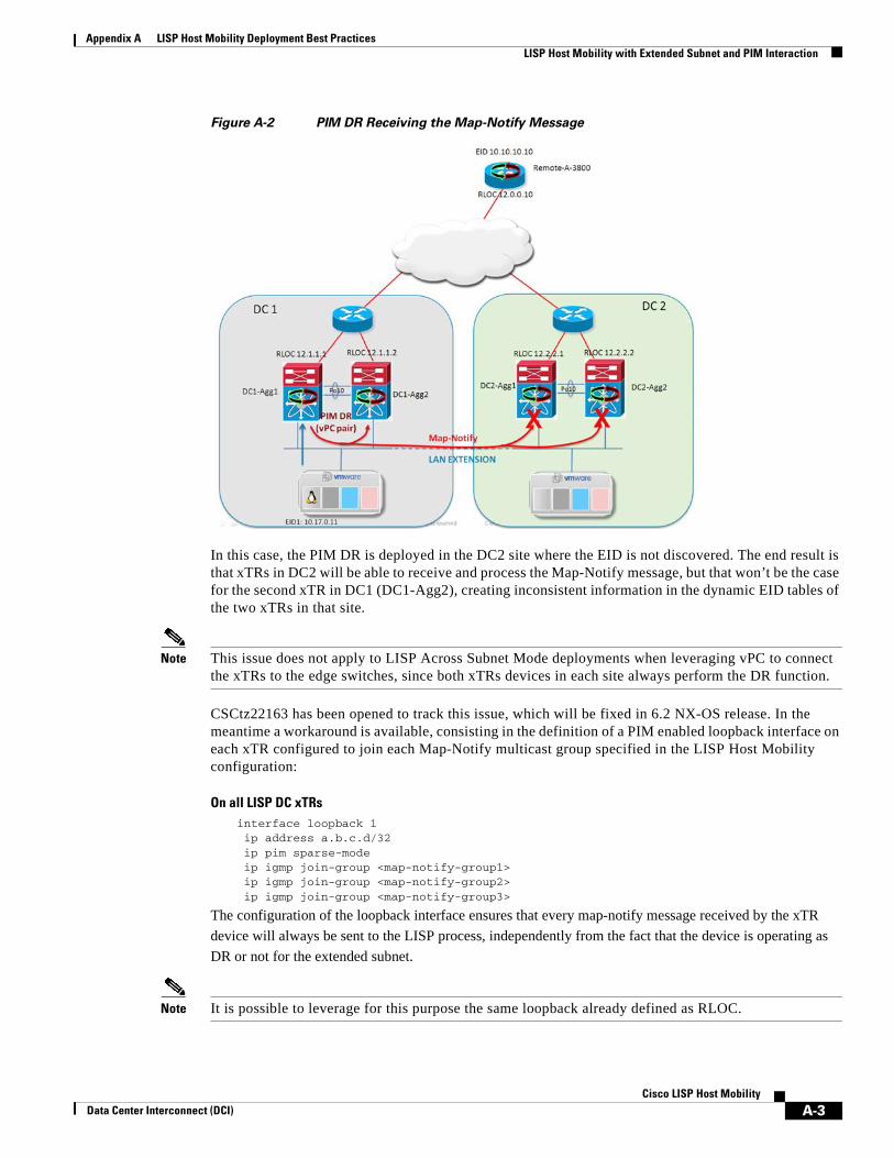
Appendix A LISP Host Mobility Deployment Best Practices LISP Host Mobility with Extended Subnet and PIM Interaction
Figure A-2 PIM DR Receiving the Map-Notify Message
In this case, the PIM DR is deployed in the DC2 site where the EID is not discovered. The end result is that xTRs in DC2 will be able to receive and process the Map-Notify message, but that won’t be the case for the second xTR in DC1 (DC1-Agg2), creating inconsistent information in the dynamic EID tables of the two xTRs in that site.
Note This issue does not apply to LISP Across Subnet Mode deployments when leveraging vPC to connect the xTRs to the edge switches, since both xTRs devices in each site always perform the DR function.
CSCtz22163 has been opened to track this issue, which will be fixed in 6.2 NX-OS release. In the meantime a workaround is available, consisting in the definition of a PIM enabled loopback interface on each xTR configured to join each Map-Notify multicast group specified in the LISP Host Mobility configuration:
On all LISP DC xTRsinterface loopback 1 ip address a.b.c.d/32 ip pim sparse-mode ip igmp join-group <map-notify-group1> ip igmp join-group <map-notify-group2> ip igmp join-group <map-notify-group3>
The configuration of the loopback interface ensures that every map-notify message received by the xTR device will always be sent to the LISP process, independently from the fact that the device is operating as DR or not for the extended subnet.
Note It is possible to leverage for this purpose the same loopback already defined as RLOC.
A-3Cisco LISP Host Mobility
Data Center Interconnect (DCI)

Appendix A LISP Host Mobility Deployment Best Practices Establishing L3 Peering between LISP DC xTR Devices
Establishing L3 Peering between LISP DC xTR DevicesA dedicated L3 link must be used between the xTRs deployed at the aggregation layer to establish L3 peering. Also, the link must terminate on M1-32 cards. This specific design consideration is highlighted in Figure A-3.
Figure A-3 Routing LISP Encapsulated Traffic between xTRs
A LISP encapsulated flow is arriving into DC1 directed to the RLOC 12.1.1.2 identifying DC1-Agg2 xTR. If that xTR loses connectivity to the L3 DC core, the only remaining L3 path from the core to the RLOC is via the transit link connecting the two xTRs. The transit link is usually a vPC peer-link configured as a L2 trunk and it is common practice to leverage a dedicate VLAN to establish a L3 peering (SVI-to-SVI) between the xTRs. When LISP encapsulated traffic is re-routed across the transit link, two scenarios are possible:
• The transit link is implemented with interfaces belonging to M1-32 linecards: in this case, the traffic cannot be LISP de-capsulated causing the black holing of all the traffic destined to 12.1.1.2.
• The transit link is implemented with interfaces belonging to F1 linecards: in this case the traffic is de-capsulated in SW once it reaches DC1-Agg2.
Both scenarios above are obviously undesirable, so the recommended workaround is to leverage a dedicated routed interface (or routed port-channel) to establish the L3 peering between xTRs, as shown in Figure A-4.
A-4Cisco LISP Host Mobility
Data Center Interconnect (DCI)

Appendix A LISP Host Mobility Deployment Best Practices Dealing with an ETR Failure Scenario
Figure A-4 Leveraging a Dedicated L3 Connection Between xTR Devices
Note Since this link can be used to send/receive LISP encapsulated traffic, it is mandatory to leverage M1-32 interfaces. No other interfaces (other M1 modules, F2, M2) are supported for this function.
Dealing with an ETR Failure ScenarioGiven the fact that communication between ITR and ETR happens in an overlay fashion, one important thing to consider is how to detect a remote (and indirect) ETR failure, to avoid the black holing of the traffic.
Figure A-5 highlights the problem, focusing on traffic flows exchanged between a remote ITR and two DC ETRs (the same considerations apply to the opposite direction).
A-5Cisco LISP Host Mobility
Data Center Interconnect (DCI)

Appendix A LISP Host Mobility Deployment Best Practices Dealing with an ETR Failure Scenario
Figure A-5 ETR Failure Scenario
On the left side we notice how traffic is normally load-balanced across both DC ETRs, leveraging the mapping information on the ITR associating the DC EID subnet to the two RLOCs A and B. As previously mentioned, the load balancing is happening assuming that the priority and weight parameters configured on the DC xTRs are matching. In that case, load balancing is performed on a per-flow basis, depending on the L2, L3 and L4 parameters of the original flow.
On the right we show the traffic behavior after the failure of one of the DC xTRs: since the map-cache information on the ITR remains valid by default for 24 hours (this value could be tune down to 15 minutes if needed), the ITR keeps using the RLOC A to send traffic to the 10.17.1.0/24 subnet, causing the black-holing of the traffic.
To avoid this issue, it is required to dynamically update the ITR map-cache information, so that RLOC A can be marked as unusable and all the traffic can be directed to RLOC B. Three mechanisms can currently be leveraged for this purpose: they are described below with relative recommendation and deployment considerations.
1. Leveraging specific RLOC prefix updates
The basic assumption for this method is that specific /32 RLOC prefixes can be exchanged between ITR and ETR, leveraging the deployed routing protocol (IGP or BGP), as shown in Figure A-6.
A-6Cisco LISP Host Mobility
Data Center Interconnect (DCI)
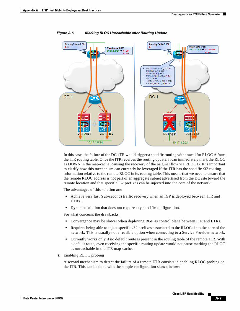
Appendix A LISP Host Mobility Deployment Best Practices Dealing with an ETR Failure Scenario
Figure A-6 Marking RLOC Unreachable after Routing Update
In this case, the failure of the DC xTR would trigger a specific routing withdrawal for RLOC A from the ITR routing table. Once the ITR receives the routing update, it can immediately mark the RLOC as DOWN in the map-cache, causing the recovery of the original flow via RLOC B. It is important to clarify how this mechanism can currently be leveraged if the ITR has the specific /32 routing information relative to the remote RLOC in its routing table. This means that we need to ensure that the remote RLOC address is not part of an aggregate subnet advertised from the DC site toward the remote location and that specific /32 prefixes can be injected into the core of the network.
The advantages of this solution are:
• Achieve very fast (sub-second) traffic recovery when an IGP is deployed between ITR and ETRs.
• Dynamic solution that does not require any specific configuration.
For what concerns the drawbacks:
• Convergence may be slower when deploying BGP as control plane between ITR and ETRs.
• Requires being able to inject specific /32 prefixes associated to the RLOCs into the core of the network. This is usually not a feasible option when connecting to a Service Provider network.
• Currently works only if no default route is present in the routing table of the remote ITR. With a default route, even receiving the specific routing update would not cause marking the RLOC as unreachable in the ITR map-cache.
2. Enabling RLOC probing
A second mechanism to detect the failure of a remote ETR consists in enabling RLOC probing on the ITR. This can be done with the simple configuration shown below:
A-7Cisco LISP Host Mobility
Data Center Interconnect (DCI)
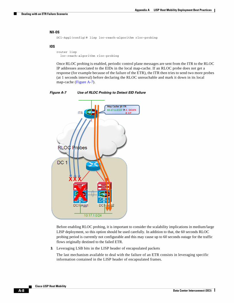
Appendix A LISP Host Mobility Deployment Best Practices Dealing with an ETR Failure Scenario
NX-OSDC1-Agg1(config)# lisp loc-reach-algorithm rloc-probing
IOSrouter lisp loc-reach-algorithm rloc-probing
Once RLOC probing is enabled, periodic control plane messages are sent from the ITR to the RLOC IP addresses associated to the EIDs in the local map-cache. If an RLOC probe does not get a response (for example because of the failure of the ETR), the ITR then tries to send two more probes (at 1 seconds interval) before declaring the RLOC unreachable and mark it down in its local map-cache (Figure A-7).
Figure A-7 Use of RLOC Probing to Detect EID Failure
Before enabling RLOC probing, it is important to consider the scalability implications in medium/large LISP deployment, so this option should be used carefully. In addition to that, the 60 seconds RLOC probing period is currently not configurable and this may cause up to 60 seconds outage for the traffic flows originally destined to the failed ETR.
3. Leveraging LSB bits in the LISP header of encapsulated packets
The last mechanism available to deal with the failure of an ETR consists in leveraging specific information contained in the LISP header of encapsulated frames.
A-8Cisco LISP Host Mobility
Data Center Interconnect (DCI)

Appendix A LISP Host Mobility Deployment Best Practices Dealing with an ETR Failure Scenario
Figure A-8 Use of LSB Bits to Communicate an RLOC Failure
As shown on the left side of Figure A-8, when both ETRs are up and running, the packets they generate destined to the remote EID subnet 10.10.10.0/24 contain in the LSB portion of the header the information that both DC1 RLOCs are available. The remote ETR that keeps load-balancing traffic toward both RLOCs A and B receive this information.
When one of the DC LISP devices fail, the peer device receives a routing update about the now missing RLOC and as a result changes the information in the LSB bits of the traffic directed to the remote ETR to inform it that only RLOC B is now up and running. The remote ETR receives the packet and leverages the LSB bits information to mark down the corresponding RLOC in the map-cache, allowing for traffic recovery via RLOC B.
The advantage of this solution is that it is enabled by default on the data plane and does not require any specific consideration on the routing protocol deployment side.
Some of the drawbacks are:
• It assumes that bidirectional flows are established between remote LISP devices, since the LSB notification is always associated to data plane traffic.
• Current Nexus 7000 LISP enabled HW (M1-32 linecards) do not allow to react to the changes applied by a remote xTR to the LSB bits value, making impossible to recover the flows destined to the remote xTR. Future HW support with F3 linecard will solve this problem.
A-9Cisco LISP Host Mobility
Data Center Interconnect (DCI)
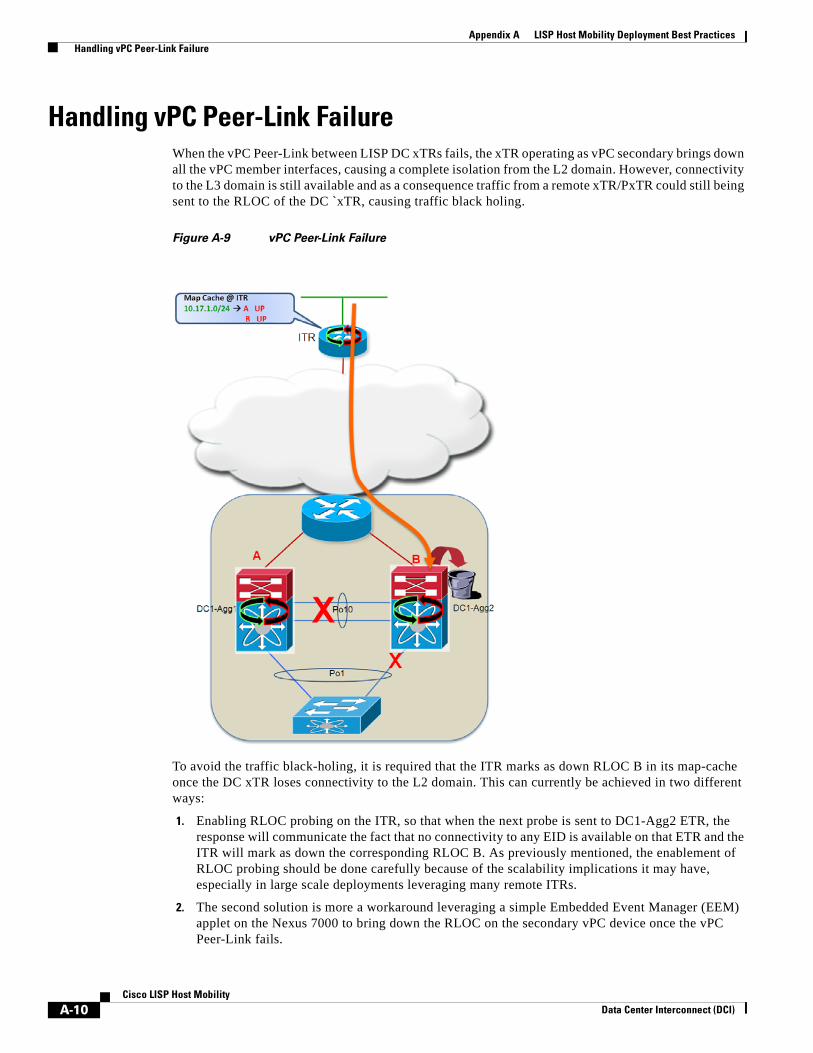
Appendix A LISP Host Mobility Deployment Best Practices Handling vPC Peer-Link Failure
Handling vPC Peer-Link FailureWhen the vPC Peer-Link between LISP DC xTRs fails, the xTR operating as vPC secondary brings down all the vPC member interfaces, causing a complete isolation from the L2 domain. However, connectivity to the L3 domain is still available and as a consequence traffic from a remote xTR/PxTR could still being sent to the RLOC of the DC `xTR, causing traffic black holing.
Figure A-9 vPC Peer-Link Failure
To avoid the traffic black-holing, it is required that the ITR marks as down RLOC B in its map-cache once the DC xTR loses connectivity to the L2 domain. This can currently be achieved in two different ways:
1. Enabling RLOC probing on the ITR, so that when the next probe is sent to DC1-Agg2 ETR, the response will communicate the fact that no connectivity to any EID is available on that ETR and the ITR will mark as down the corresponding RLOC B. As previously mentioned, the enablement of RLOC probing should be done carefully because of the scalability implications it may have, especially in large scale deployments leveraging many remote ITRs.
2. The second solution is more a workaround leveraging a simple Embedded Event Manager (EEM) applet on the Nexus 7000 to bring down the RLOC on the secondary vPC device once the vPC Peer-Link fails.
A-10Cisco LISP Host Mobility
Data Center Interconnect (DCI)
Appendix A LISP Host Mobility Deployment Best Practices LISP and Services (FW, SLB) Integration Considerations
The specific applet that allows achieving this result is shown below.event manager applet Suspend_LISP event syslog pattern "Peer-link going down, suspending all vPCs on secondary" action 1.0 cli conf t action 2.0 cli interface lo1 action 2.1 cli shut action 9.0 syslog msg Suspend LISP after vPC Peer-link failure
The applet above shuts down the loopback interface used as RLOC (Loopback 1) once the vPC secondary device notices that the peer-link has failed.
In a similar fashion, the RLOC loopback is reactivated when the peer-link recovers:event manager applet Reactivate_LISP event syslog pattern "vPC restore timer expired, reiniting vPCs" action 0.5 cli sleep 120 action 1.0 cli conf t action 2.0 cli interface lo1 action 2.1 cli no shut action 9.0 syslog msg Reactivate LISP after vPC Peer-link recovery
Notice how an artificial delay of 2 minutes is added to ensure that the recovering xTR has enough time to receive EID information from the peer xTR (via Map-notify messages).
LISP and Services (FW, SLB) Integration ConsiderationsIntegration of network services, such as Firewalls (FW) and Server Load Balancing (SLB) devices, in a LISP-enabled architecture currently represent an important design challenge. The main problem is that these devices usually work in a stateful fashion (i.e. maintain information about the “state” of each specific traffic flow that traverses them), so specific attention needs to be paid when leveraging LISP to steer flows between data center sites, to avoid the creation of asymmetric traffic patterns.
FW and LISP xTR PositioningThe first thing to consider when discussing the relative positioning of a FW and the LISP xTR is that currently the FW must be deployed “south” of the LISP device. This is mandatory to allow the enforcement of security policies on original IP packets and it is the consequence of the UDP encapsulation that the xTR performs on the original IP packets.
Note When deploying the FW “north” of the LISP xTR, the only policy enforcement allowed is a stateless ACL permitting UDP traffic on port 4341 (LISP encapsulated traffic).
There are two possible design options for the deployment of the FW south of the xTR:
Option 1: FW in routed mode between the default gateway and the LISP xTR
The deployment model (Figure A-10) positioning the FW in routed mode north of the default gateway has become very popular and has been validated and documented as part of the Virtualized Multi-Service Data Center (VMDC) designs.
Note For more information on VMDC designs please refer to the link below: http://www.cisco.com/en/US/solutions/ns340/ns414/ns742/ns743/ns1050/landing_vmdc.html
A-11Cisco LISP Host Mobility
Data Center Interconnect (DCI)
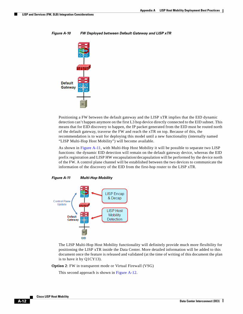
Appendix A LISP Host Mobility Deployment Best Practices LISP and Services (FW, SLB) Integration Considerations
Figure A-10 FW Deployed between Default Gateway and LISP xTR
Positioning a FW between the default gateway and the LISP xTR implies that the EID dynamic detection can’t happen anymore on the first L3 hop device directly connected to the EID subnet. This means that for EID discovery to happen, the IP packet generated from the EID must be routed north of the default gateway, traverse the FW and reach the xTR on top. Because of this, the recommendation is to wait for deploying this model until a new functionality (internally named “LISP Multi-Hop Host Mobility”) will become available.
As shown in Figure A-11, with Multi-Hop Host Mobility it will be possible to separate two LISP functions: the dynamic EID detection will remain on the default gateway device, whereas the EID prefix registration and LISP HW encapsulation/decapsulation will be performed by the device north of the FW. A control plane channel will be established between the two devices to communicate the information of the discovery of the EID from the first-hop router to the LISP xTR.
Figure A-11 Multi-Hop Mobility
The LISP Multi-Hop Host Mobility functionality will definitely provide much more flexibility for positioning the LISP xTR inside the Data Center. More detailed information will be added to this document once the feature is released and validated (at the time of writing of this document the plan is to have it by Q1CY13).
Option 2: FW in transparent mode or Virtual Firewall (VSG)
This second approach is shown in Figure A-12.
A-12Cisco LISP Host Mobility
Data Center Interconnect (DCI)

Appendix A LISP Host Mobility Deployment Best Practices LISP and Services (FW, SLB) Integration Considerations
Figure A-12 FW in Transparent Mode and VSG
In this case the FW will be deployed in L2 (transparent or bridged) mode or, in a virtualized type of deployment, leveraging the Virtual Services Gateway (VSG) functionality available with Nexus1000v.
Note For more information about VSG and Nexus1000v deployment please refer to the document below: http://www.cisco.com/en/US/docs/solutions/Enterprise/Data_Center/DCI/4.0/EMC/EMC.pdf
In both models above, the LISP xTR device remains co-located on the first-hop router (default-gateway) so all the deployment considerations and configuration steps previously discussed remain valid. The only additional step required for the dynamic discovery of the EID is to ensure that traffic generated by this device can flow across the FW (physical or virtual) to reach the LISP xTR upstream.
When looking at an end-to-end Data Center Interconnect (DCI) architecture leveraging physical FW devices, there are two possible deployment models.
The first one, shown in Figure A-13, leverages an independent pair of Active/Standby FW nodes in each data center location.
A-13Cisco LISP Host Mobility
Data Center Interconnect (DCI)
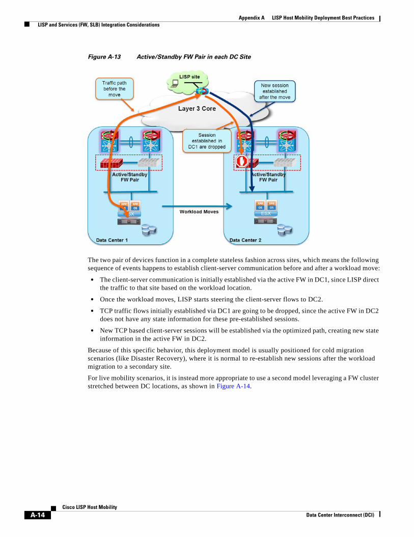
Appendix A LISP Host Mobility Deployment Best Practices LISP and Services (FW, SLB) Integration Considerations
Figure A-13 Active/Standby FW Pair in each DC Site
The two pair of devices function in a complete stateless fashion across sites, which means the following sequence of events happens to establish client-server communication before and after a workload move:
• The client-server communication is initially established via the active FW in DC1, since LISP direct the traffic to that site based on the workload location.
• Once the workload moves, LISP starts steering the client-server flows to DC2.
• TCP traffic flows initially established via DC1 are going to be dropped, since the active FW in DC2 does not have any state information for these pre-established sessions.
• New TCP based client-server sessions will be established via the optimized path, creating new state information in the active FW in DC2.
Because of this specific behavior, this deployment model is usually positioned for cold migration scenarios (like Disaster Recovery), where it is normal to re-establish new sessions after the workload migration to a secondary site.
For live mobility scenarios, it is instead more appropriate to use a second model leveraging a FW cluster stretched between DC locations, as shown in Figure A-14.
A-14Cisco LISP Host Mobility
Data Center Interconnect (DCI)
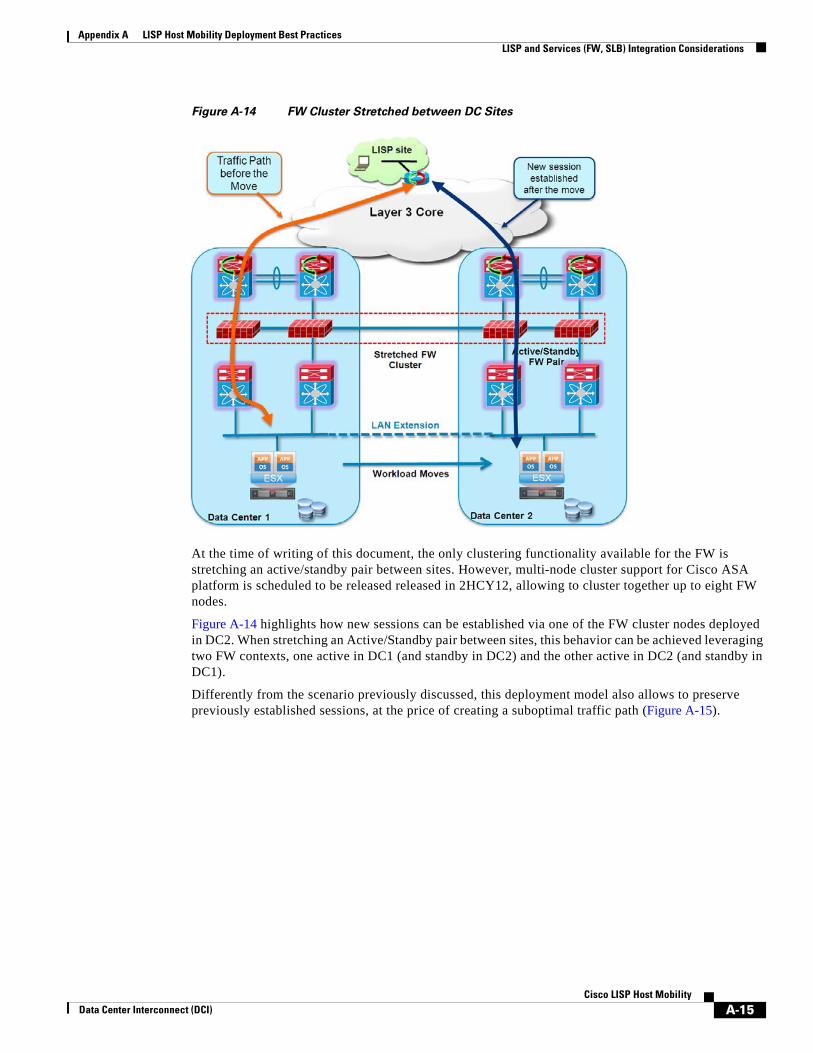
Appendix A LISP Host Mobility Deployment Best Practices LISP and Services (FW, SLB) Integration Considerations
Figure A-14 FW Cluster Stretched between DC Sites
At the time of writing of this document, the only clustering functionality available for the FW is stretching an active/standby pair between sites. However, multi-node cluster support for Cisco ASA platform is scheduled to be released released in 2HCY12, allowing to cluster together up to eight FW nodes.
Figure A-14 highlights how new sessions can be established via one of the FW cluster nodes deployed in DC2. When stretching an Active/Standby pair between sites, this behavior can be achieved leveraging two FW contexts, one active in DC1 (and standby in DC2) and the other active in DC2 (and standby in DC1).
Differently from the scenario previously discussed, this deployment model also allows to preserve previously established sessions, at the price of creating a suboptimal traffic path (Figure A-15).
A-15Cisco LISP Host Mobility
Data Center Interconnect (DCI)
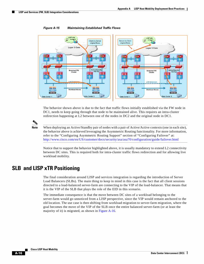
Appendix A LISP Host Mobility Deployment Best Practices LISP and Services (FW, SLB) Integration Considerations
Figure A-15 Maintaining Established Traffic Flows
The behavior shown above is due to the fact that traffic flows initially established via the FW node in DC1, needs to keep going through that node to be maintained alive. This requires an intra-cluster redirection happening at L2 between one of the nodes in DC2 and the original node in DC1.
Note When deploying an Active/Standby pair of nodes with a pair of Active/Active contexts (one in each site), the behavior above is achieved leveraging the Asymmetric Routing functionality. For more information, refer to the “Configuring Asymmetric Routing Support” section of “Configuring Failover” at: http://www.cisco.com/en/US/customer/docs/security/asa/asa70/configuration/guide/failover.html
Notice that to support the behavior highlighted above, it is usually mandatory to extend L2 connectivity between DC sites. This is required both for intra-cluster traffic flows redirection and for allowing live workload mobility.
SLB and LISP xTR PositioningThe final consideration around LISP and services integration is regarding the introduction of Server Load Balancers (SLBs). The main thing to keep in mind in this case is the fact that all client sessions directed to a load-balanced server-farm are connecting to the VIP of the load-balancer. That means that it is the VIP of the SLB that plays the role of the EID in this scenario.
The immediate consequence is that the move between DC sites of a workload belonging to the server-farm would go unnoticed from a LISP perspective, since the VIP would remain anchored to the old location. The use case is then shifting from workload migration to server-farm migration, where the goal becomes the move of the VIP of the SLB once the entire balanced server-farm (or at least the majority of it) is migrated, as shown in Figure A-16.
A-16Cisco LISP Host Mobility
Data Center Interconnect (DCI)
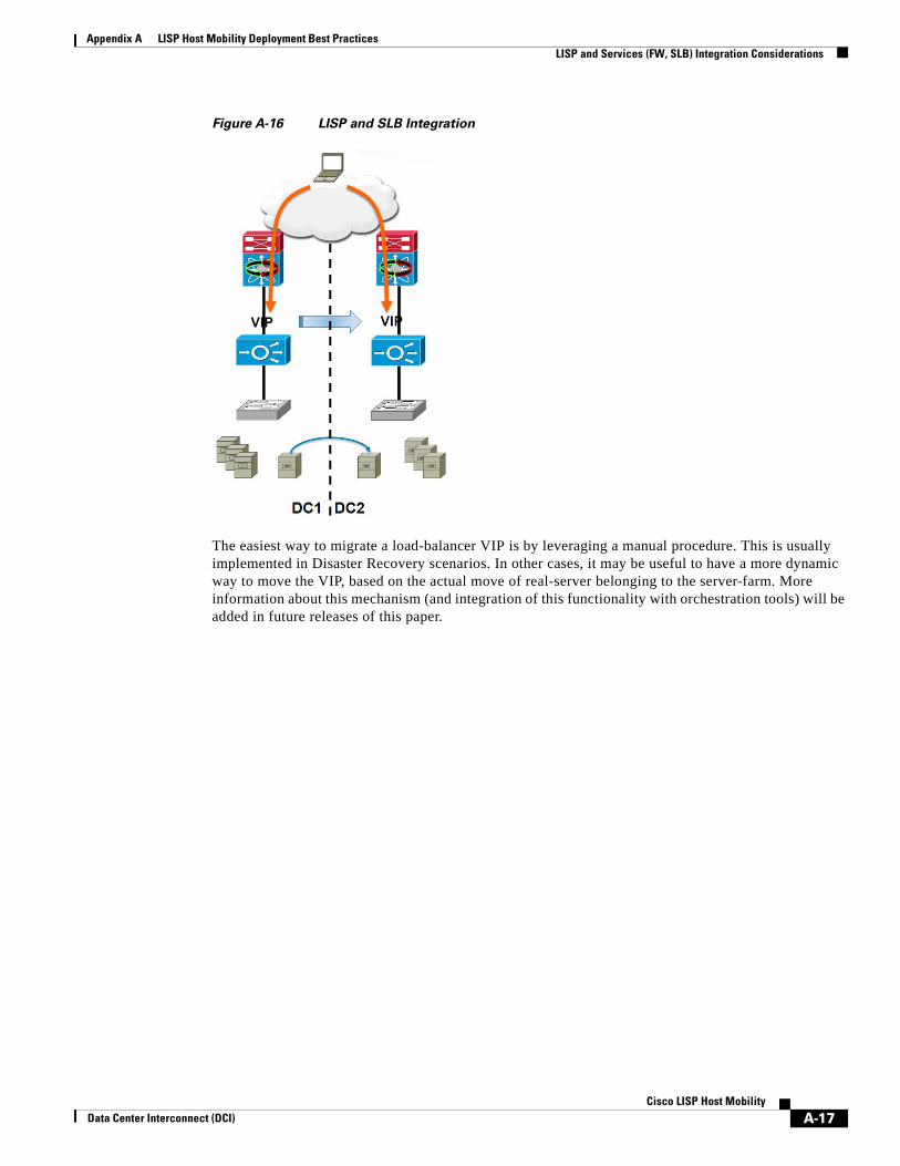
Appendix A LISP Host Mobility Deployment Best Practices LISP and Services (FW, SLB) Integration Considerations
Figure A-16 LISP and SLB Integration
The easiest way to migrate a load-balancer VIP is by leveraging a manual procedure. This is usually implemented in Disaster Recovery scenarios. In other cases, it may be useful to have a more dynamic way to move the VIP, based on the actual move of real-server belonging to the server-farm. More information about this mechanism (and integration of this functionality with orchestration tools) will be added in future releases of this paper.
A-17Cisco LISP Host Mobility
Data Center Interconnect (DCI)

Appendix A LISP Host Mobility Deployment Best Practices LISP and Services (FW, SLB) Integration Considerations
A-18Cisco LISP Host Mobility
Data Center Interconnect (DCI)