Cisco IOS Voice Commands: I
78
VR-923 Cisco IOS Voice Command Reference Cisco IOS Voice Commands: I This chapter contains commands to configure and maintain Cisco IOS voice applications. The commands are presented in alphabetical order. Some commands required for configuring voice may be found in other Cisco IOS command references. Use the master index of commands or search online to find these commands. For detailed information on how to configure these applications and features, refer to the Cisco IOS Voice Configuration Library.
Transcript of Cisco IOS Voice Commands: I
VR-923Cisco IOS Voice Command Reference
Cisco IOS Voice Commands:I
This chapter contains commands to configure and maintain Cisco IOS voice applications. The commands are presented in alphabetical order. Some commands required for configuring voice may be found in other Cisco IOS command references. Use the master index of commands or search online to find these commands.
For detailed information on how to configure these applications and features, refer to the Cisco IOS Voice Configuration Library.

Cisco IOS Voice Commands: Iicpif
VR-924Cisco IOS Voice Command Reference
icpifTo specify the Calculated Planning Impairment Factor (ICPIF) for calls sent by a dial peer, use the icpif command in dial peer configuration mode. To reset to the default, use the no form of this command.
icpif number
no icpif
Syntax Description
Command Default 20
Command Modes Dial peer configuration
Command History
Usage Guidelines This command is applicable only to VoIP dial peers.
Use this command to specify the maximum acceptable impairment factor for the voice calls sent by the selected dial peer.
Examples The following example disables the icpif command:
dial-peer voice 10 voipicpif 0
number Integer, expressed in equipment impairment factor units, that specifies the ICPIF value. Range is 0 to 55. The default is 20.
Release Modification
11.3(1)T This command was introduced on the Cisco 3600 series.
12.0(7)XK This command was implemented on the Cisco MC3810.
12.1(2)T This command was integrated into Cisco IOS Release 12.1(2)T.
12.2(8)T The number default value for this command was changed from 30 to 20.
Cisco IOS Voice Commands: Iid
VR-925Cisco IOS Voice Command Reference
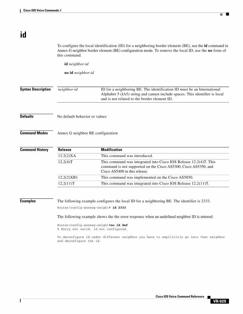
idTo configure the local identification (ID) for a neighboring border element (BE), use the id command in Annex G neighbor border element (BE) configuration mode. To remove the local ID, use the no form of this command.
id neighbor-id
no id neighbor-id
Syntax Description
Defaults No default behavior or values
Command Modes Annex G neighbor BE configuration
Command History
Examples The following example configures the local ID for a neighboring BE. The identifier is 2333.
Router(config-annexg-neigh)# id 2333
The following example shows the the error response when an undefined neighbor ID is entered:
Router(config-annexg-neigh)#no id def % Entry not valid, id not configured.
To deconfigure id under different neighbor you have to expilicitly go into that neighbor and deconfigure the id.
neighbor-id ID for a neighboring BE. The identification ID must be an International Alphabet 5 (IA5) string and cannot include spaces. This identifier is local and is not related to the border element ID.
Release Modification
12.2(2)XA This command was introduced.
12.2(4)T This command was integrated into Cisco IOS Release 12.2(4)T. This command is not supported on the Cisco AS5300, Cisco AS5350, and Cisco AS5400 in this release.
12.2(2)XB1 This command was implemented on the Cisco AS5850.
12.2(11)T This command was integrated into Cisco IOS Release 12.2(11)T.
Cisco IOS Voice Commands: Iid
VR-926Cisco IOS Voice Command Reference
Related Commands Command Description
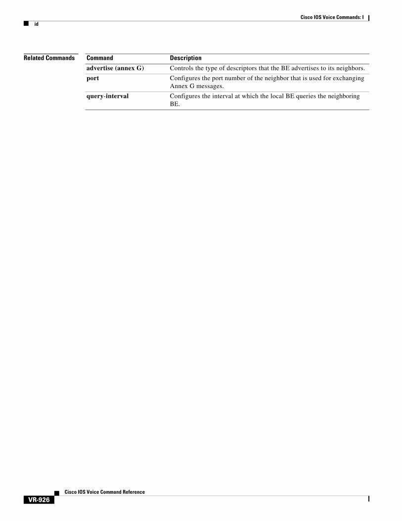
advertise (annex G) Controls the type of descriptors that the BE advertises to its neighbors.
port Configures the port number of the neighbor that is used for exchanging Annex G messages.
query-interval Configures the interval at which the local BE queries the neighboring BE.
Cisco IOS Voice Commands: Iidle-voltage
VR-927Cisco IOS Voice Command Reference
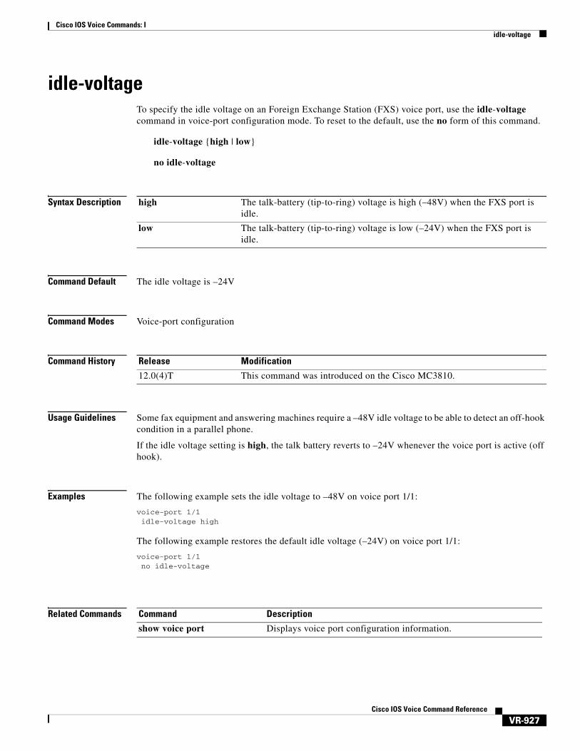
idle-voltageTo specify the idle voltage on an Foreign Exchange Station (FXS) voice port, use the idle-voltage command in voice-port configuration mode. To reset to the default, use the no form of this command.
idle-voltage {high | low}
no idle-voltage
Syntax Description
Command Default The idle voltage is –24V
Command Modes Voice-port configuration
Command History
Usage Guidelines Some fax equipment and answering machines require a –48V idle voltage to be able to detect an off-hook condition in a parallel phone.
If the idle voltage setting is high, the talk battery reverts to –24V whenever the voice port is active (off hook).
Examples The following example sets the idle voltage to –48V on voice port 1/1:
voice-port 1/1idle-voltage high
The following example restores the default idle voltage (–24V) on voice port 1/1:
voice-port 1/1no idle-voltage
Related Commands
high The talk-battery (tip-to-ring) voltage is high (–48V) when the FXS port is idle.
low The talk-battery (tip-to-ring) voltage is low (–24V) when the FXS port is idle.
Release Modification
12.0(4)T This command was introduced on the Cisco MC3810.
Command Description
show voice port Displays voice port configuration information.

Cisco IOS Voice Commands: Iignore
VR-928Cisco IOS Voice Command Reference
ignoreTo configure the North American E&M or E&M MELCAS voice port to ignore specific receive bits, use the ignore command in voice-port configuration mode. To reset to the default, use the no form of this command.
ignore {rx-a-bit | rx-b-bit | rx-c-bit | rx-d-bit}
no ignore {rx-a-bit | rx-b-bit | rx-c-bit | rx-d-bit}
Syntax Description
Command Default The default is mode-dependent:
• North American E&M:
– The receive B, C, and D bits are ignored
– The receive A bit is not ignored
• E&M MELCAS:
– The receive A bit is ignored
– The receive B, C, and D bits are not ignored
Command Modes Voice-port configuration
Command History
Usage Guidelines The ignore command applies to E&M digital voice ports associated with T1/E1 controllers. Repeat the command for each receive bit to be configured. Use this command with the define command.
rx-a-bit Ignores the receive A bit.
rx-b-bit Ignores the receive B bit.
rx-c-bit Ignores the receive C bit.
rx-d-bit Ignores the receive D bit.
Release Modification
11.3(1)MA This command was introduced on the Cisco MC3810.
12.0(7)XK This command was implemented on the Cisco 2600 series and Cisco 3600 series.
12.1(2)T This command was integrated into Cisco IOS Release 12.1(2)T.
Cisco IOS Voice Commands: Iignore
VR-929Cisco IOS Voice Command Reference
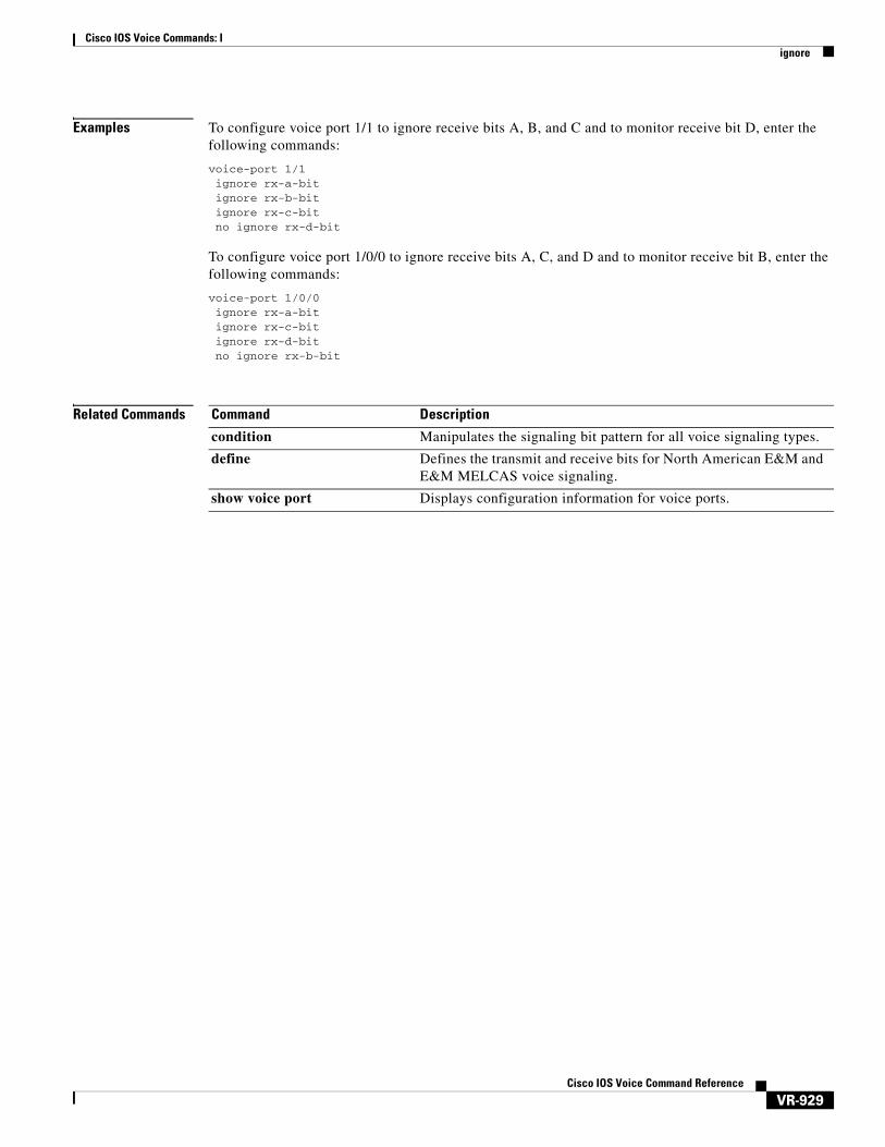
Examples To configure voice port 1/1 to ignore receive bits A, B, and C and to monitor receive bit D, enter the following commands:
voice-port 1/1ignore rx-a-bitignore rx-b-bitignore rx-c-bitno ignore rx-d-bit
To configure voice port 1/0/0 to ignore receive bits A, C, and D and to monitor receive bit B, enter the following commands:
voice-port 1/0/0ignore rx-a-bitignore rx-c-bitignore rx-d-bitno ignore rx-b-bit
Related Commands Command Description
condition Manipulates the signaling bit pattern for all voice signaling types.
define Defines the transmit and receive bits for North American E&M and E&M MELCAS voice signaling.
show voice port Displays configuration information for voice ports.
Cisco IOS Voice Commands: Iignore (interface)
VR-930Cisco IOS Voice Command Reference
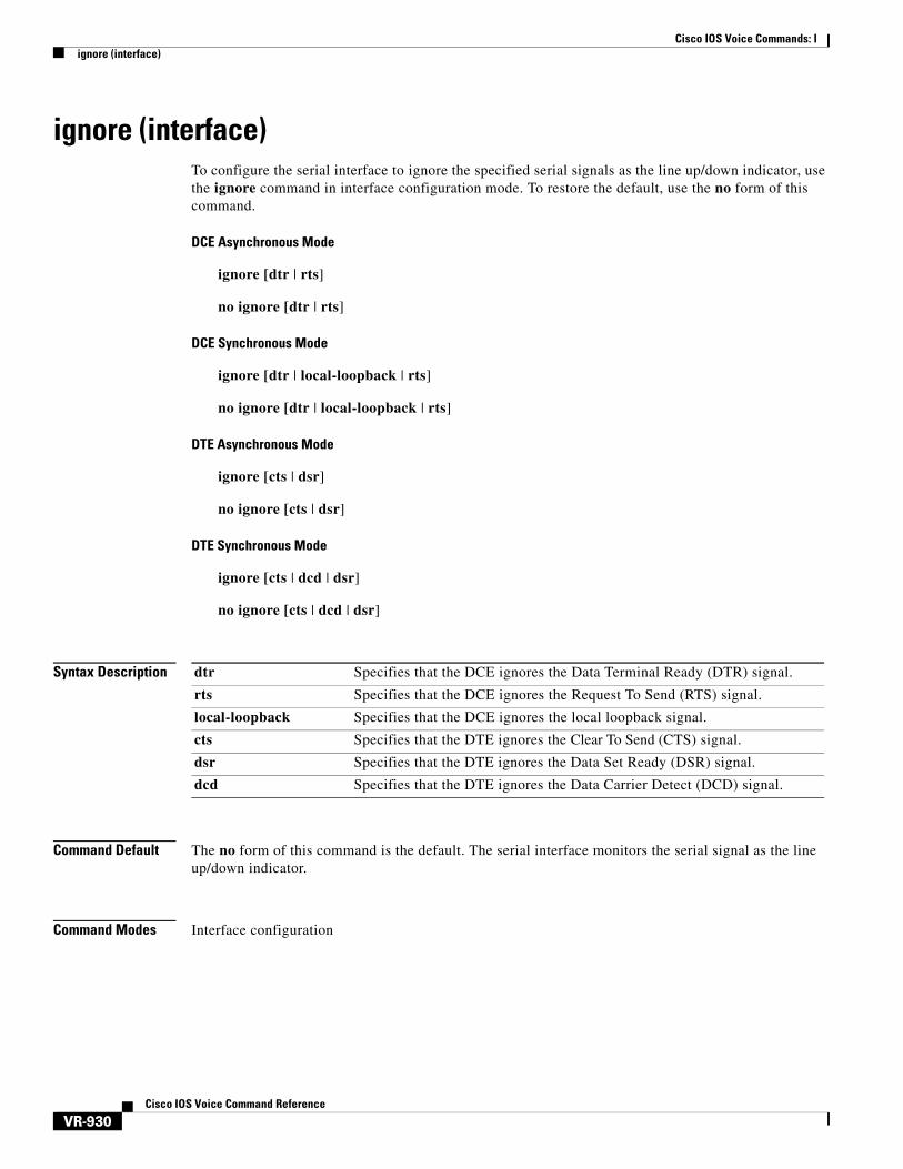
ignore (interface)To configure the serial interface to ignore the specified serial signals as the line up/down indicator, use the ignore command in interface configuration mode. To restore the default, use the no form of this command.
DCE Asynchronous Mode
ignore [dtr | rts]
no ignore [dtr | rts]
DCE Synchronous Mode
ignore [dtr | local-loopback | rts]
no ignore [dtr | local-loopback | rts]
DTE Asynchronous Mode
ignore [cts | dsr]
no ignore [cts | dsr]
DTE Synchronous Mode
ignore [cts | dcd | dsr]
no ignore [cts | dcd | dsr]
Syntax Description
Command Default The no form of this command is the default. The serial interface monitors the serial signal as the line up/down indicator.
Command Modes Interface configuration
dtr Specifies that the DCE ignores the Data Terminal Ready (DTR) signal.
rts Specifies that the DCE ignores the Request To Send (RTS) signal.
local-loopback Specifies that the DCE ignores the local loopback signal.
cts Specifies that the DTE ignores the Clear To Send (CTS) signal.
dsr Specifies that the DTE ignores the Data Set Ready (DSR) signal.
dcd Specifies that the DTE ignores the Data Carrier Detect (DCD) signal.

Cisco IOS Voice Commands: Iignore (interface)
VR-931Cisco IOS Voice Command Reference
Command History
Usage Guidelines Serial Interfaces in DTE Mode
When the serial interface is operating in DTE mode, it monitors the DCD signal as the line up/down indicator. By default, the attached DCE device sends the DCD signal. When the DTE interface detects the DCD signal, it changes the state of the interface to up.
SDLC Multidrop Environments
In some configurations, such as a Synchronous Data Link Control (SDLC) multidrop environment, the DCE device sends the DSR signal instead of the DCD signal, which prevents the interface from coming up. Use this command to tell the interface to monitor the DSR signal instead of the DCD signal as the line up/down indicator.
Examples The following example shows how to configure serial interface 0 to ignore the DCD signal as the line up/down indicator:
Router(config)# interface serial 0Router(config-if)# ignore dcd
Related Commands
Release Modification
12.2(15)ZJ This command was introduced on the following platforms: Cisco 2610XM, Cisco 2611XM, Cisco 2620XM, Cisco 2621XM, Cisco 2650XM, Cisco 2651XM, Cisco 2691, Cisco 3631, Cisco 3660, Cisco 3725, and Cisco 3745 routers.
12.3(2)T This command was integrated into Cisco IOS Release 12.3(2)T.
Command Description
debug serial lead-transition Activates the leads status transition debug capability for all capable ports.
show interfaces serial Displays information about a serial interface.
Cisco IOS Voice Commands: Iimage encoding
VR-932Cisco IOS Voice Command Reference
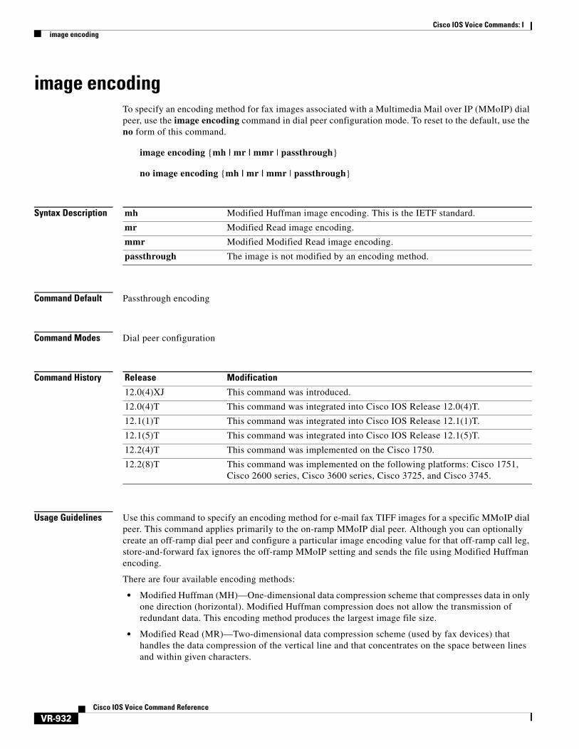
image encodingTo specify an encoding method for fax images associated with a Multimedia Mail over IP (MMoIP) dial peer, use the image encoding command in dial peer configuration mode. To reset to the default, use the no form of this command.
image encoding {mh | mr | mmr | passthrough}
no image encoding {mh | mr | mmr | passthrough}
Syntax Description
Command Default Passthrough encoding
Command Modes Dial peer configuration
Command History
Usage Guidelines Use this command to specify an encoding method for e-mail fax TIFF images for a specific MMoIP dial peer. This command applies primarily to the on-ramp MMoIP dial peer. Although you can optionally create an off-ramp dial peer and configure a particular image encoding value for that off-ramp call leg, store-and-forward fax ignores the off-ramp MMoIP setting and sends the file using Modified Huffman encoding.
There are four available encoding methods:
• Modified Huffman (MH)—One-dimensional data compression scheme that compresses data in only one direction (horizontal). Modified Huffman compression does not allow the transmission of redundant data. This encoding method produces the largest image file size.
• Modified Read (MR)—Two-dimensional data compression scheme (used by fax devices) that handles the data compression of the vertical line and that concentrates on the space between lines and within given characters.
mh Modified Huffman image encoding. This is the IETF standard.
mr Modified Read image encoding.
mmr Modified Modified Read image encoding.
passthrough The image is not modified by an encoding method.
Release Modification
12.0(4)XJ This command was introduced.
12.0(4)T This command was integrated into Cisco IOS Release 12.0(4)T.
12.1(1)T This command was integrated into Cisco IOS Release 12.1(1)T.
12.1(5)T This command was integrated into Cisco IOS Release 12.1(5)T.
12.2(4)T This command was implemented on the Cisco 1750.
12.2(8)T This command was implemented on the following platforms: Cisco 1751, Cisco 2600 series, Cisco 3600 series, Cisco 3725, and Cisco 3745.
Cisco IOS Voice Commands: Iimage encoding
VR-933Cisco IOS Voice Command Reference
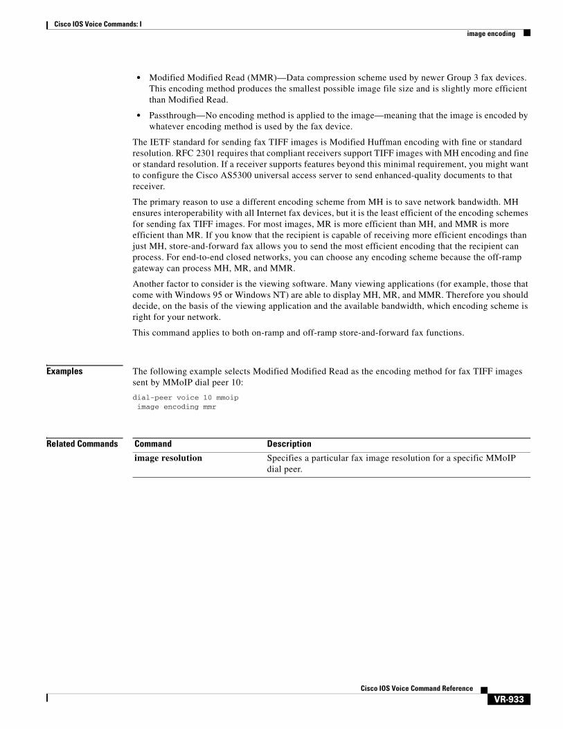
• Modified Modified Read (MMR)—Data compression scheme used by newer Group 3 fax devices. This encoding method produces the smallest possible image file size and is slightly more efficient than Modified Read.
• Passthrough—No encoding method is applied to the image—meaning that the image is encoded by whatever encoding method is used by the fax device.
The IETF standard for sending fax TIFF images is Modified Huffman encoding with fine or standard resolution. RFC 2301 requires that compliant receivers support TIFF images with MH encoding and fine or standard resolution. If a receiver supports features beyond this minimal requirement, you might want to configure the Cisco AS5300 universal access server to send enhanced-quality documents to that receiver.
The primary reason to use a different encoding scheme from MH is to save network bandwidth. MH ensures interoperability with all Internet fax devices, but it is the least efficient of the encoding schemes for sending fax TIFF images. For most images, MR is more efficient than MH, and MMR is more efficient than MR. If you know that the recipient is capable of receiving more efficient encodings than just MH, store-and-forward fax allows you to send the most efficient encoding that the recipient can process. For end-to-end closed networks, you can choose any encoding scheme because the off-ramp gateway can process MH, MR, and MMR.
Another factor to consider is the viewing software. Many viewing applications (for example, those that come with Windows 95 or Windows NT) are able to display MH, MR, and MMR. Therefore you should decide, on the basis of the viewing application and the available bandwidth, which encoding scheme is right for your network.
This command applies to both on-ramp and off-ramp store-and-forward fax functions.
Examples The following example selects Modified Modified Read as the encoding method for fax TIFF images sent by MMoIP dial peer 10:
dial-peer voice 10 mmoipimage encoding mmr
Related Commands Command Description
image resolution Specifies a particular fax image resolution for a specific MMoIP dial peer.
Cisco IOS Voice Commands: Iimage resolution
VR-934Cisco IOS Voice Command Reference
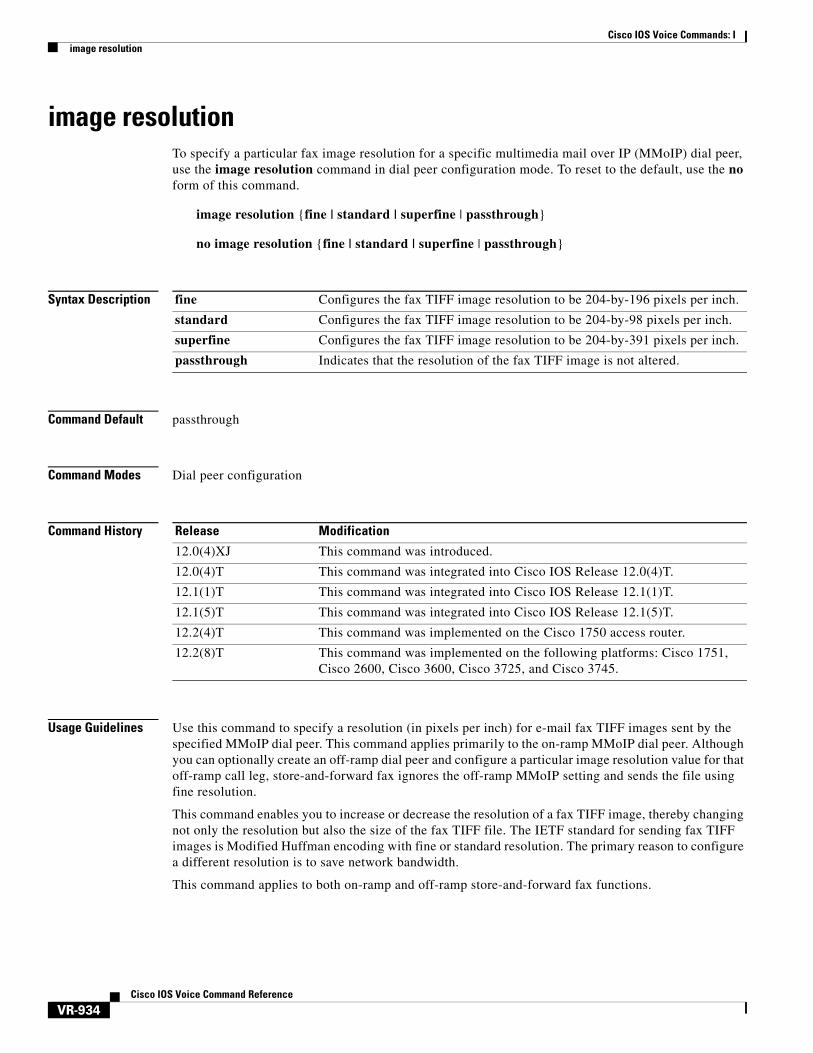
image resolutionTo specify a particular fax image resolution for a specific multimedia mail over IP (MMoIP) dial peer, use the image resolution command in dial peer configuration mode. To reset to the default, use the no form of this command.
image resolution {fine | standard | superfine | passthrough}
no image resolution {fine | standard | superfine | passthrough}
Syntax Description
Command Default passthrough
Command Modes Dial peer configuration
Command History
Usage Guidelines Use this command to specify a resolution (in pixels per inch) for e-mail fax TIFF images sent by the specified MMoIP dial peer. This command applies primarily to the on-ramp MMoIP dial peer. Although you can optionally create an off-ramp dial peer and configure a particular image resolution value for that off-ramp call leg, store-and-forward fax ignores the off-ramp MMoIP setting and sends the file using fine resolution.
This command enables you to increase or decrease the resolution of a fax TIFF image, thereby changing not only the resolution but also the size of the fax TIFF file. The IETF standard for sending fax TIFF images is Modified Huffman encoding with fine or standard resolution. The primary reason to configure a different resolution is to save network bandwidth.
This command applies to both on-ramp and off-ramp store-and-forward fax functions.
fine Configures the fax TIFF image resolution to be 204-by-196 pixels per inch.
standard Configures the fax TIFF image resolution to be 204-by-98 pixels per inch.
superfine Configures the fax TIFF image resolution to be 204-by-391 pixels per inch.
passthrough Indicates that the resolution of the fax TIFF image is not altered.
Release Modification
12.0(4)XJ This command was introduced.
12.0(4)T This command was integrated into Cisco IOS Release 12.0(4)T.
12.1(1)T This command was integrated into Cisco IOS Release 12.1(1)T.
12.1(5)T This command was integrated into Cisco IOS Release 12.1(5)T.
12.2(4)T This command was implemented on the Cisco 1750 access router.
12.2(8)T This command was implemented on the following platforms: Cisco 1751, Cisco 2600, Cisco 3600, Cisco 3725, and Cisco 3745.

Cisco IOS Voice Commands: Iimage resolution
VR-935Cisco IOS Voice Command Reference
Examples The following example selects fine resolution (204-by-196 pixels per inch) for e-mail fax TIFF images associated with MMoIP dial peer 10:
dial-peer voice 10 mmoipimage encoding mhimage resolution fine
Related Commands Command Description
image encoding Specifies an encoding method for fax images associated with an MMoIP dial peer.

Cisco IOS Voice Commands: Iimpedance
VR-936Cisco IOS Voice Command Reference
impedanceTo specify the terminating impedance of a voice-port interface, use the impedance command in voice-port configuration mode. To reset to the default, use the no form of this command.
impedance {600c | 600r | 900c | 900r | complex1 | complex2 | complex3 | complex4 | complex5 | complex6}
no impedance {600c | 600r | 900c | 900r | complex1 | complex2 | complex3 | complex4 | complex5 | complex6}
Syntax Description
Note This table represents the full set of impedances. Not all modules support the full set of impedance values shown here. To determine which impedance values are available on your modules, enter impedance ? in the command-line interface to see a list of the values you can configure.
Command Default 600r
Command Modes Voice-port configuration
Command History
600c 600 ohms + 2.15uF1.
600r Resistive 600-ohm termination.
900c 900 ohms + 2.15uF1.
900r Resistive 900-ohm termination.
complex1 220 ohms + (820 ohms || 115 nF)1.
complex2 270 ohms + (750 ohms || 150 nF)1.
complex3 370 ohms + (620 ohms || 310 nF)1.
complex4 600r, line = 270 ohms + (750 ohms || 150 nF)1.
complex5 320 + (1050 ohms || 230 nF), line = 12 Kft1.
complex6 600r, line = 350 + (1000 ohms || 210 nF)1.
1. The plus symbol (+) indicates serial. The double pipe ( || ) indicates parallel.
Release Modification
11.3(1)T This command was introduced on Cisco 3600 series.
12.3(7)T This command was integrated into Cisco IOS Release 12.3(7)T and support was added for the complex3, complex4, complex5, and complex6 keywords on the Cisco 2600XM series, Cisco 2691, Cisco 2800 series, Cisco 3662 (telco models), Cisco 3700 series, and Cisco 3800 series.

Cisco IOS Voice Commands: Iimpedance
VR-937Cisco IOS Voice Command Reference
Usage Guidelines Use this command to specify the terminating impedance of analog telephony interfaces. The impedance value must match the specifications from the telephony system to which it is connected. Different countries often have different standards for impedance. CO switches in the United States are predominantly 600r. PBXs in the United States are 600r or 900c.
If the impedance is set incorrectly (if there is an impedance mismatch), a significant amount of echo is generated (which could be masked if the echo-cancel command has been enabled). In addition, gains might not work correctly if there is an impedance mismatch.
Configuring the impedance on a voice port changes the impedance on both voice ports of a VPM card. This voice port must be shut down and then opened for the new value to take effect.
Examples The following example configures an FXO voice port on the Cisco 3600 series router for an impedance of 600 ohms (real):
voice-port 1/0/0impedance 600rshutdown/no shutdown
The following example configures an E&M voice port on a Cisco 2800 for an impedance of complex3:
voice-port 1/1impedance complex3shutdown/no shutdown
Related Commands Command Description
voice-port Enters voice-port configuration mode.
echo-cancel enable Enables the cancellation of voice that is sent out the interface and received back on the same interface.

Cisco IOS Voice Commands: Iinband-alerting
VR-938Cisco IOS Voice Command Reference
inband-alertingTo enable inband alerting, use the inband-alerting command in the SIP user agent configuration mode. To disable inband alerting, use the no form of this command.
inband-alerting
no inband-alerting
Syntax Description This command has no arguments or keywords.
Command Default Enabled
Command Modes SIP user agent configuration
Command History
Usage Guidelines If inband alerting is enabled, the originating gateway can open an early media path (upon receiving a 180 or 183 message with a SDP body). Inband alerting allows the terminating gateway or switch to feed tones or announcements before a call is connected. If inband alerting is disabled, local alerting is generated on the originating gateway.
To reset this command to the default value, use the default command.
Examples The following example disables inband alerting:
Router(config)# sip-uaRouter(config-sip-ua)# no inband-alerting
Related Commands
Release Modification
12.1(1)T This command was introduced.
12.1(3)T This command was limited to enabling and disabling inband alerting.
12.2(2)XA This command was implemented on the Cisco AS5350 and Cisco AS5400.
12.2(2)XB1 This command was introduced on the Cisco AS5850.
12.2(11)T This command was integrated into Cisco IOS Release 12.2(11)T.
Command Description
default Sets a command to its default.
exit Exits the SIP user agent configuration mode.
max-forwards Specifies the maximum number of hops for a request.
no Negates a command or set its defaults.
retry Configures the SIP signaling timers for retry attempts.

Cisco IOS Voice Commands: Iinband-alerting
VR-939Cisco IOS Voice Command Reference
timers Configures the SIP signaling timers.
transport Enables SIP UA transport for TCP/UDP.
Command Description
Cisco IOS Voice Commands: Iinbound ttl
VR-940Cisco IOS Voice Command Reference
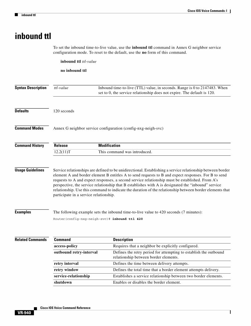
inbound ttlTo set the inbound time-to-live value, use the inbound ttl command in Annex G neighbor service configuration mode. To reset to the default, use the no form of this command.
inbound ttl ttl-value
no inbound ttl
Syntax Description
Defaults 120 seconds
Command Modes Annex G neighbor service configuration (config-nxg-neigh-svc)
Command History
Usage Guidelines Service relationships are defined to be unidirectional. Establishing a service relationship between border element A and border element B entitles A to send requests to B and expect responses. For B to send requests to A and expect responses, a second service relationship must be established. From A’s perspective, the service relationship that B establishes with A is designated the “inbound” service relationship. Use this command to indicate the duration of the relationship between border elements that participate in a service relationship.
Examples The following example sets the inbound time-to-live value to 420 seconds (7 minutes):
Router(config-nxg-neigh-svc)# inbound ttl 420
Related Commands
ttl-value Inbound time-to-live (TTL) value, in seconds. Range is 0 to 2147483. When set to 0, the service relationship does not expire. The default is 120.
Release Modification
12.2(11)T This command was introduced.
Command Description
access-policy Requires that a neighbor be explicitly configured.
outbound retry-interval Defines the retry period for attempting to establish the outbound relationship between border elements.
retry interval Defines the time between delivery attempts.
retry window Defines the total time that a border element attempts delivery.
service-relationship Establishes a service relationship between two border elements.
shutdown Enables or disables the border element.

Cisco IOS Voice Commands: Iincoming alerting
VR-941Cisco IOS Voice Command Reference
incoming alertingTo instruct an FXO ground-start voice port to modify its means of detecting an incoming call, use the incoming alerting command in voice-port configuration mode. To return to the default call detection method, use the no form of this command.
incoming alerting {ring-only}
no incoming alerting
Syntax Description
Command Default The FXO ground-start voice port detects an incoming call either by detecting the ring voltage applied to the line by the PSTN central office (CO) or by detecting that tip-ground is present for greater than about 7 seconds.
Command Modes Voice-port configuration
Command History
Usage Guidelines This command is valid only on FXO ports that have been configured with the signal ground-start command.
This command is necessary when two Cisco Unified CallManager Express (Cisco Unified CME) routers are used to provide redundant failover for incoming PSTN FXO ground-start lines. The voice ports for these trunk lines are wired in parallel between the two routers. The primary router is set to answer incoming calls after the first ring by default. The secondary router is set to answer incoming calls after 2 or 3 rings using the ring number command in voice-port configuration mode. As long as the primary router is operating, then the secondary router will not see enough rings to trigger it to answer the call. When the primary router is not operating, the secondary router has to be able to detect incoming ring signals so that it can answer calls. The default method of incoming call detection is not appropriate for voice ports on a secondary Cisco Unified CME router. The incoming alerting ring-only command must be used to modify the incoming call detection logic so that the voice port counts the number of incoming call rings instead of using the default call detection method.
Examples The following example sets ring-only as the detection method for incoming calls on voice port 3/0/0, which is an FXO ground-start voice port.
Router(config)# voice-port 3/0/0Router(config-voiceport)# signal ground-startRouter(config-voiceport)# incoming alerting ring-only
ring-only Count incoming rings to detect incoming calls to the voice port that should be answered by the router.
Cisco IOS Release Modification
12.4(4)XC This command was introduced.
Cisco IOS Voice Commands: Iincoming alerting
VR-942Cisco IOS Voice Command Reference
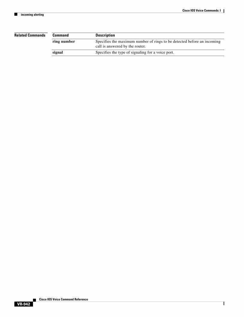
Related Commands Command Description
ring number Specifies the maximum number of rings to be detected before an incoming call is answered by the router.
signal Specifies the type of signaling for a voice port.
Cisco IOS Voice Commands: Iincoming called-number (call filter match list)
VR-943Cisco IOS Voice Command Reference
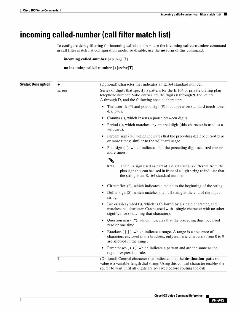
incoming called-number (call filter match list)To configure debug filtering for incoming called numbers, use the incoming called-number command in call filter match list configuration mode. To disable, use the no form of this command.
incoming called-number [+]string[T]
no incoming called-number [+]string[T]
Syntax Description + (Optional) Character that indicates an E.164 standard number.
string Series of digits that specify a pattern for the E.164 or private dialing plan telephone number. Valid entries are the digits 0 through 9, the letters A through D, and the following special characters:
• The asterisk (*) and pound sign (#) that appear on standard touch-tone dial pads.
• Comma (,), which inserts a pause between digits.
• Period (.), which matches any entered digit (this character is used as a wildcard).
• Percent sign (%), which indicates that the preceding digit occurred zero or more times; similar to the wildcard usage.
• Plus sign (+), which indicates that the preceding digit occurred one or more times.
Note The plus sign used as part of a digit string is different from the plus sign that can be used in front of a digit string to indicate that the string is an E.164 standard number.
• Circumflex (^), which indicates a match to the beginning of the string.
• Dollar sign ($), which matches the null string at the end of the input string.
• Backslash symbol (\), which is followed by a single character, and matches that character. Can be used with a single character with no other significance (matching that character).
• Question mark (?), which indicates that the preceding digit occurred zero or one time.
• Brackets ( [ ] ), which indicate a range. A range is a sequence of characters enclosed in the brackets; only numeric characters from 0 to 9 are allowed in the range.
• Parentheses ( ( ) ), which indicate a pattern and are the same as the regular expression rule.
T (Optional) Control character that indicates that the destination-pattern value is a variable-length dial string. Using this control character enables the router to wait until all digits are received before routing the call.

Cisco IOS Voice Commands: Iincoming called-number (call filter match list)
VR-944Cisco IOS Voice Command Reference
Command Default No default behavior or values
Command Modes Call filter match list configuration
Command History
Examples The following example shows the voice call debug filter set to match incoming called number 5550123:
call filter match-list 1 voiceincoming called-number 5550123
Related Commands
Release Modification
12.3(4)T This command was introduced.
Command Description
call filter match-list voice Create a call filter match list for debugging voice calls.
debug condition match-list
Run a filtered debug on a voice call.
incoming calling-number Configure debug filtering for incoming calling numbers.
incoming dialpeer Configure debug filtering for the incoming dial peer.
incoming secondary-called-number
Configure debug filtering for incoming called numbers from the second stage of a two-stage scenario.
outgoing called-number Configure debug filtering for outgoing called numbers.
outgoing calling-number Configure debug filtering for outgoing calling numbers.
outgoing dialpeer Configure debug filtering for the outgoing dial peer.
show call filter match-list Display call filter match lists.

Cisco IOS Voice Commands: Iincoming called-number (dial peer)
VR-945Cisco IOS Voice Command Reference
incoming called-number (dial peer)To specify a digit string that can be matched by an incoming call to associate the call with a dial peer, use the incoming called-number command in dial-peer configuration mode. To reset to the default, use the no form of this command.
incoming called-number [+]string[T]
no incoming called-number [+]string[T]
Syntax Description + (Optional) Character that indicates an E.164 standard number.
string Series of digits that specify a pattern for the E.164 or private dialing plan telephone number. Valid entries are the digits 0 through 9, the letters A through D, and the following special characters:
• The asterisk (*) and pound sign (#) that appear on standard touch-tone dial pads.
• Comma (,), which inserts a pause between digits.
• Period (.), which matches any entered digit (this character is used as a wildcard).
• Percent sign (%), which indicates that the preceding digit occurred zero or more times; similar to the wildcard usage.
• Plus sign (+), which indicates that the preceding digit occurred one or more times.
Note The plus sign used as part of a digit string is different from the plus sign that can be used in front of a digit string to indicate that the string is an E.164 standard number.
• Circumflex (^), which indicates a match to the beginning of the string.
• Dollar sign ($), which matches the null string at the end of the input string.
• Backslash symbol (\), which is followed by a single character, and matches that character. Can be used with a single character with no other significance (matching that character).
• Question mark (?), which indicates that the preceding digit occurred zero or one time.
• Brackets ( [ ] ), which indicate a range. A range is a sequence of characters enclosed in the brackets; only numeric characters from 0 to 9 are allowed in the range.
• Parentheses ( ( ) ), which indicate a pattern and are the same as the regular expression rule.
T (Optional) Control character that indicates that the destination-pattern value is a variable-length dial string. Using this control character enables the router to wait until all digits are received before routing the call.

Cisco IOS Voice Commands: Iincoming called-number (dial peer)
VR-946Cisco IOS Voice Command Reference
Command Default No incoming called number is defined
Command Modes Dial peer configuration
Command History
Usage Guidelines When a Cisco device is handling both modem and voice calls, it needs to be able to identify the service type of the call—meaning whether the incoming call to the server is a modem or a voice call. When the access server handles only modem calls, the service type identification is handled through modem pools. Modem pools associate calls with modem resources based on the dialed number identification service (DNIS). In a mixed environment, in which the server receives both modem and voice calls, you need to identify the service type of a call by using this command.
If you do not use this command, the server attempts to resolve whether an incoming call is a modem or voice call on the basis of the interface over which the call arrives. If the call comes in over an interface associated with a modem pool, the call is assumed to be a modem call; if a call comes in over a voice port associated with a dial peer, the call is assumed to be a voice call.
By default, there is no called number associated with the dial peer, which means that incoming calls are associated with dial peers by matching calling number with answer address, call number with destination pattern, or calling interface with configured interface.
Use this command to define the destination telephone number for a particular dial peer. For the on-ramp POTS dial peer, this telephone number is the DNIS number of the incoming fax call. For the off-ramp MMoIP dial peer, this telephone number is the telephone number of the destination fax machine.
This command applies to both VoIP and POTS dial peers and to on-ramp and off-ramp store-and-forward fax functions.
This command is also used to provide a matching VoIP dial peer on the basis of called number when fax or modem pass-through with named signaling events (NSEs) is defined globally on a terminating gateway.
You can ensure that all calls will match at least one dial peer by using the following commands:
Router(config)# dial-peer voice tag voipRouter(config-dial-peer)# incoming called-number.
Release Modification
11.3(1)T This command was introduced on the Cisco 3600 series.
11.3NA This command was implemented on the Cisco AS5800.
12.0(4)XJ This command was modified for store-and-forward fax.
12.0(4)T This command was integrated into Cisco IOS Release 12.0(4)T.
12.0(7)XK This command was implemented on the Cisco MC3810.
12.1(2)T This command was integrated into Cisco IOS Release 12.1(2)T.
12.1(5)T This command was integrated into Cisco IOS Release 12.1(5)T.
12.2(4)T This command was implemented on the Cisco 1750.
12.2(8)T This command was implemented on the following platforms: Cisco 1751, Cisco 2600 series, Cisco 3600 series, Cisco 3725, and Cisco 3745.

Cisco IOS Voice Commands: Iincoming called-number (dial peer)
VR-947Cisco IOS Voice Command Reference
Examples The following example configures calls that come into the router with a called number of 555-0163 as being voice calls:
dial peer voice 10 potsincoming called-number 5550163
The following example sets the number (310) 555-0142 as the incoming called number for MMoIP dial peer 10:
dial-peer voice 10 mmoipincoming called-number 3105550142

Cisco IOS Voice Commands: Iincoming calling-number (call filter match list)
VR-948Cisco IOS Voice Command Reference
incoming calling-number (call filter match list)To configure debug filtering for incoming calling numbers, use the incoming calling-number command in call filter match list configuration mode. To disable, use the no form of this command.
incoming calling-number [+]string[T]
no incoming calling-number [+]string[T]
Syntax Description + (Optional) Character that indicates an E.164 standard number.
string Series of digits that specify a pattern for the E.164 or private dialing plan telephone number. Valid entries are the digits 0 through 9, the letters A through D, and the following special characters:
• The asterisk (*) and pound sign (#) that appear on standard touch-tone dial pads.
• Comma (,), which inserts a pause between digits.
• Period (.), which matches any entered digit (this character is used as a wildcard).
• Percent sign (%), which indicates that the preceding digit occurred zero or more times; similar to the wildcard usage.
• Plus sign (+), which indicates that the preceding digit occurred one or more times.
Note The plus sign used as part of a digit string is different from the plus sign that can be used in front of a digit string to indicate that the string is an E.164 standard number.
• Circumflex (^), which indicates a match to the beginning of the string.
• Dollar sign ($), which matches the null string at the end of the input string.
• Backslash symbol (\), which is followed by a single character, and matches that character. Can be used with a single character with no other significance (matching that character).
• Question mark (?), which indicates that the preceding digit occurred zero or one time.
• Brackets ( [ ] ), which indicate a range. A range is a sequence of characters enclosed in the brackets; only numeric characters from 0 to 9 are allowed in the range.
• Parentheses ( ( ) ), which indicate a pattern and are the same as the regular expression rule.
T (Optional) Control character that indicates that the destination-pattern value is a variable-length dial string. Using this control character enables the router to wait until all digits are received before routing the call.

Cisco IOS Voice Commands: Iincoming calling-number (call filter match list)
VR-949Cisco IOS Voice Command Reference
Command Default No default behavior or values
Command Modes Call filter match list configuration
Command History
Examples The following example shows the voice call debug filter set to match incoming calling number 5550125:
call filter match-list 1 voice incoming calling-number 5550125
Related Commands
Release Modification
12.3(4)T This command was introduced.
Command Description
call filter match-list voice Create a call filter match list for debugging voice calls.
debug condition match-list
Run a filtered debug on a voice call.
incoming called-number (call filter match list)
Configure debug filtering for incoming called numbers.
incoming dialpeer Configure debug filtering for the incoming dial peer.
incoming secondary-called-number
Configure debug filtering for incoming called numbers from the second stage of a two-stage scenario.
outgoing called-number Configure debug filtering for outgoing called numbers.
outgoing calling-number Configure debug filtering for outgoing calling numbers.
outgoing dialpeer Configure debug filtering for the outgoing dial peer.
show call filter match-list Display call filter match lists.
Cisco IOS Voice Commands: Iincoming dialpeer
VR-950Cisco IOS Voice Command Reference
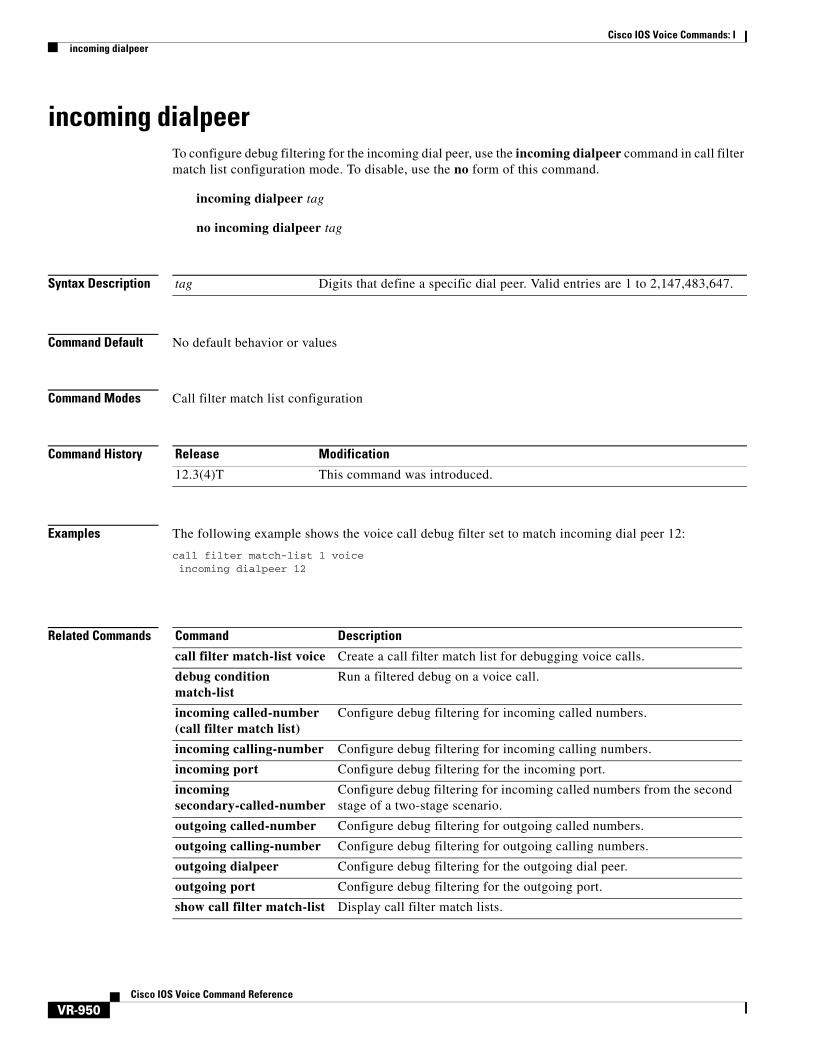
incoming dialpeer To configure debug filtering for the incoming dial peer, use the incoming dialpeer command in call filter match list configuration mode. To disable, use the no form of this command.
incoming dialpeer tag
no incoming dialpeer tag
Syntax Description
Command Default No default behavior or values
Command Modes Call filter match list configuration
Command History
Examples The following example shows the voice call debug filter set to match incoming dial peer 12:
call filter match-list 1 voiceincoming dialpeer 12
Related Commands
tag Digits that define a specific dial peer. Valid entries are 1 to 2,147,483,647.
Release Modification
12.3(4)T This command was introduced.
Command Description
call filter match-list voice Create a call filter match list for debugging voice calls.
debug condition match-list
Run a filtered debug on a voice call.
incoming called-number (call filter match list)
Configure debug filtering for incoming called numbers.
incoming calling-number Configure debug filtering for incoming calling numbers.
incoming port Configure debug filtering for the incoming port.
incoming secondary-called-number
Configure debug filtering for incoming called numbers from the second stage of a two-stage scenario.
outgoing called-number Configure debug filtering for outgoing called numbers.
outgoing calling-number Configure debug filtering for outgoing calling numbers.
outgoing dialpeer Configure debug filtering for the outgoing dial peer.
outgoing port Configure debug filtering for the outgoing port.
show call filter match-list Display call filter match lists.

Cisco IOS Voice Commands: Iincoming media local ipv4
VR-951Cisco IOS Voice Command Reference
incoming media local ipv4 To configure debug filtering for the incoming media local IPv4 addresses for the voice gateway receiving the media stream, use the incoming media local ipv4 command in call filter match list configuration mode. To disable, use the no form of this command.
incoming media local ipv4 ip_address
no incoming media local ipv4 ip_address
Syntax Description
Command Default No default behavior or values
Command Modes Call filter match list configuration
Command History
Examples The following example shows the voice call debug filter set to match incoming media on the local voice gateway, which has IP address 192.168.10.255:
call filter match-list 1 voiceincoming media local ipv4 192.168.10.255
Related Commands
ip_address IP address of the local voice gateway
Release Modification
12.3(4)T This command was introduced.
Command Description
call filter match-list voice Create a call filter match list for debugging voice calls.
debug condition match-list
Run a filtered debug on a voice call.
incoming media remote ipv4
Configure debug filtering for the incoming media IPv4 addresses for calls to the IP side from the remote IP device.
incoming port Configure debug filtering for the incoming port.
outgoing media local ipv4 Configure debug filtering for the outgoing media IPv4 addresses for calls to the IP side from the local voice gateway.
outgoing media remote ipv4
Configure debug filtering for the outgoing media IPv4 addresses for calls to the IP side from the remote IP device.
outgoing port Configure debug filtering for the outgoing port.
show call filter match-list Display call filter match lists.
Cisco IOS Voice Commands: Iincoming media remote ipv4
VR-952Cisco IOS Voice Command Reference
incoming media remote ipv4 To configure debug filtering for the incoming media remote IPv4 addresses for the voice gateway receiving the media stream, use the incoming media remote ipv4 command in call filter match list configuration mode. To disable, use the no form of this command.
incoming media remote ipv4 ip_address
no incoming media remote ipv4 ip_address
Syntax Description
Command Default No default behavior or values
Command Modes Call filter match list configuration
Command History
Examples The following example shows the voice call debug filter set to match incoming media on the remote IP device, which has IP address 192.168.10.255:
call filter match-list 1 voiceincoming media remote ipv4 192.168.10.255
Related Commands
ip_address IP address of the remote IP device
Release Modification
12.3(4)T This command was introduced.
Command Description
call filter match-list voice Create a call filter match list for debugging voice calls.
debug condition match-list
Run a filtered debug on a voice call.
incoming media local ipv4 Configure debug filtering for the incoming media IPv4 addresses for calls to the IP side from the local voice gateway.
incoming port Configure debug filtering for the incoming port.
outgoing media local ipv4 Configure debug filtering for the outgoing media IPv4 addresses for calls to the IP side from the local voice gateway
outgoing media remote ipv4
Configure debug filtering for the outgoing media IPv4 addresses for calls to the IP side from the remote IP device.
outgoing port Configure debug filtering for the outgoing port.
show call filter match-list Display call filter match lists.

Cisco IOS Voice Commands: Iincoming port
VR-953Cisco IOS Voice Command Reference
incoming port To configure debug filtering for the incoming port, use the incoming port command in call filter match list configuration mode. To disable, use the no form of this command.
Cisco 2600, Cisco 3600, and Cisco 3700 Series
incoming port {slot-number/subunit-number/port | slot/port:ds0-group-no}
no incoming port {slot-number/subunit-number/port | slot/port:ds0-group-no}
Cisco 2600 and Cisco 3600 Series with a High-Density Analog Network Module (NM-HDA)
incoming port {slot-number/subunit-number/port}
no incoming port {slot-number/subunit-number/port}
Cisco AS5300
incoming port controller-number:D
no incoming port controller-number:D
Cisco AS5400
incoming port card/port:D
no incoming port card/port:D
Cisco AS5800
incoming port {shelf/slot/port:D | shelf/slot/parent:port:D}
no incoming port {shelf/slot/port:D | shelf/slot/parent:port:D}
Cisco MC3810
incoming port slot/port
no incoming port slot/port
Syntax Description Cisco 2600, Cisco 3600 Series and Cisco 3700 Series
slot-number Number of the slot in the router in which the VIC is installed. Valid entries are 0 to 3, depending on the slot in which it has been installed.
subunit-number Subunit on the VIC in which the voice port is located. Valid entries are 0 or 1.
port Voice port number. Valid entries are 0 and 1.
slot The router location in which the voice port adapter is installed. Valid entries are 0 to 3.

Cisco IOS Voice Commands: Iincoming port
VR-954Cisco IOS Voice Command Reference
Cisco AS5300
Cisco AS5400
Cisco AS5800
Cisco MC3810
Command Default No default behavior or values
port: Indicates the voice interface card location. Valid entries are 0 and 3.
ds0-group-no Indicates the defined DS0 group number. Each defined DS0 group number is represented on a separate voice port. This allows you to define individual DS0s on the digital T1/E1 card.
controller-number T1 or E1 controller.
:D D channel associated with ISDN PRI.
card Specifies the T1 or E1 card. Valid entries for the card argument are 1 to 7.
port Specifies the voice port number. Valid entries are 0 to 7.
:D Indicates the D channel associated with ISDN PRI.
shelf Specifies the T1 or E1 controller on the T1 card, or the T1 controller on the T3 card. Valid entries for the shelf argument are 0 to 9999.
slot Specifies the T1 or E1 controller on the T1 card, or the T1 controller on the T3 card. Valid entries for the slot argument are 0 to 11.
port Specifies the voice port number.
• T1 or E1 controller on the T1 card —Valid entries are 0 to 11.
• T1 controller on the T3 card—Valid entries are 1 to 28.
:port Specifies the value for the parent argument. The valid entry is 0.
:D Indicates the D channel associated with ISDN PRI.
slot The slot argument specifies the number slot in the router in which the VIC is installed. The only valid entry is 1.
port The port variable specifies the voice port number. Valid interface ranges are as follows:
• T1—ANSI T1.403 (1989), Telcordia TR-54016.
• E1— ITU G.703.
• Analog Voice—Up to six ports (FXS, FXO, E & M).
• Digital Voice— Single T1/E1 with cross-connect drop and insert, CAS and CCS signaling, PRI QSIG.
• Ethernet—Single 10BASE-T.
• Serial—Two five-in-one synchronous serial (ANSI EIA/TA-530, EIA/TA-232, EIA/TA-449; ITU V.35, X.21, Bisync, Polled async).
Cisco IOS Voice Commands: Iincoming port
VR-955Cisco IOS Voice Command Reference
Command Modes Call filter match list configuration
Command History
Examples The following example shows the voice call debug filter set to match incoming port 1/1/1 on a Cisco 3660 voice gateway:
call filter match-list 1 voiceincoming port 1/1/1
Related Commands
Release Modification
12.3(4)T This command was introduced.
Command Description
call filter match-list voice Create a call filter match list for debugging voice calls.
debug condition match-list
Run a filtered debug on a voice call.
outgoing port Configure debug filtering for the outgoing port.
show call filter match-list Display call filter match lists.
Cisco IOS Voice Commands: Iincoming secondary-called-number
VR-956Cisco IOS Voice Command Reference
incoming secondary-called-number To configure debug filtering for incoming called numbers from the second stage of a two-stage scenario, use the incoming secondary-called-number command in call filter match list configuration mode. To disable, use the no form of this command.
incoming secondary-called-number string
no incoming secondary-called-number string
Syntax Description
Command Default No default behavior or values
string Series of digits that specify a pattern for the E.164 or private dialing plan telephone number. Valid entries are the digits 0 to 9, the letters A to D, and the following special characters:
• The asterisk (*) and pound sign (#) that appear on standard touchtone dial pads. On the Cisco 3600 series routers only, these characters cannot be used as leading characters in a string (for example, *650).
• Comma (,), which inserts a pause between digits.
• Period (.), which matches any entered digit (this character is used as a wildcard). On the Cisco 3600 series routers, the period cannot be used as a leading character in a string (for example, .650).
• Percent sign (%), which indicates that the preceding digit occurred zero or more times; similar to the wildcard usage.
• Plus sign (+), which indicates that the preceding digit occurred one or more times.
Note The plus sign used as part of a digit string is different from the plus sign that can be used in front of a digit string to indicate that the string is an E.164 standard number.
• Circumflex (^), which indicates a match to the beginning of the string.
• Dollar sign ($), which matches the null string at the end of the input string.
• Backslash symbol (\), which is followed by a single character; matches that character. Can be used with a single character with no other significance (matching that character).
• Question mark (?), which indicates that the preceding digit occurred zero or one time.
• Brackets ( [ ] ), which indicate a range. A range is a sequence of characters enclosed in the brackets; only numeric characters 0 to 9 are allowed in the range.
• Parentheses ( ), which indicate a pattern and are the same as the regular expression rule.
Cisco IOS Voice Commands: Iincoming secondary-called-number
VR-957Cisco IOS Voice Command Reference
Command Modes Call filter match list configuration
Command History
Usage Guidelines Two-stage dialing occurs when the voice gateway presents a dial-tone before accepting digits. When a voice call comes into the Cisco IOS voice gateway, the voice port on the router is seized inbound by a PBX or CO switch. The voice gateway then presents a dial tone to the caller and collects digits until it can identify an outbound dial-peer. Dial-peer matching is done digit-by-digit whether the digits are dialed with irregular intervals by humans or in a regular fashion by telephony equipment sending the precollected digits. The voice gateway attempts to match a dial-peer after each digit is received.
Examples The following example shows the voice call debug filter set to match incoming secondary called number 8288807:
call filter match-list 1 voice incoming secondary-called-number 8288807
Related Commands
Release Modification
12.3(4)T This command was introduced.
Command Description
call filter match-list voice Create a call filter match list for debugging voice calls.
debug condition match-list
Run a filtered debug on a voice call.
incoming called-number (call filter match list)
Configure debug filtering for incoming called numbers.
incoming calling-number Configure debug filtering for incoming calling numbers.
incoming dialpeer Configure debug filtering for the incoming dial peer.
outgoing called-number Configure debug filtering for outgoing called numbers.
outgoing calling-number Configure debug filtering for outgoing calling numbers.
outgoing dialpeer Configure debug filtering for the outgoing dial peer.
show call filter match-list Display call filter match lists.

Cisco IOS Voice Commands: Iincoming signaling local ipv4
VR-958Cisco IOS Voice Command Reference
incoming signaling local ipv4 To configure debug filtering for the incoming signaling local IPv4 addresses for the gatekeeper managing the signaling, use the incoming signaling local ipv4 command in call filter match list configuration mode. To disable, use the no form of this command.
incoming signaling local ipv4 ip_address
no incoming signaling local ipv4 ip_address
Syntax Description
Command Default No default behavior or values
Command Modes Call filter match list configuration
Command History
Examples The following example shows the voice call debug filter set to match incoming signaling on the local voice gateway, which has IP address 192.168.10.255:
call filter match-list 1 voiceincoming signaling local ipv4 192.168.10.255
Related Commands
ip_address IP address of the local voice gateway
Release Modification
12.3(4)T This command was introduced.
Command Description
call filter match-list voice Create a call filter match list for debugging voice calls.
debug condition match-list
Run a filtered debug on a voice call.
incoming port Configure debug filtering for the incoming port.
incoming signaling remote ipv4
Configure debug filtering for the incoming signaling IPv4 addresses for calls to the IP side from the remote IP device.
outgoing port Configure debug filtering for the outgoing port.
outgoing signaling local ipv4
Configure debug filtering for the outgoing signaling IPv4 addresses for calls to the IP side from the local voice gateway.
outgoing signaling remote ipv4
Configure debug filtering for the outgoing signaling IPv4 addresses for calls to the IP side from the remote IP device.
show call filter match-list Display call filter match lists.
Cisco IOS Voice Commands: Iincoming signaling remote ipv4
VR-959Cisco IOS Voice Command Reference
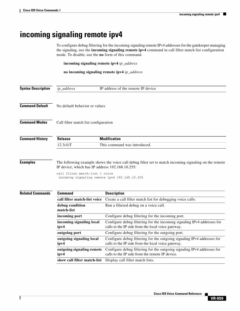
incoming signaling remote ipv4 To configure debug filtering for the incoming signaling remote IPv4 addresses for the gatekeeper managing the signaling, use the incoming signaling remote ipv4 command in call filter match list configuration mode. To disable, use the no form of this command.
incoming signaling remote ipv4 ip_address
no incoming signaling remote ipv4 ip_address
Syntax Description
Command Default No default behavior or values
Command Modes Call filter match list configuration
Command History
Examples The following example shows the voice call debug filter set to match incoming signaling on the remote IP device, which has IP address 192.168.10.255:
call filter match-list 1 voiceincoming signaling remote ipv4 192.168.10.255
Related Commands
ip_address IP address of the remote IP device
Release Modification
12.3(4)T This command was introduced.
Command Description
call filter match-list voice Create a call filter match list for debugging voice calls.
debug condition match-list
Run a filtered debug on a voice call.
incoming port Configure debug filtering for the incoming port.
incoming signaling local ipv4
Configure debug filtering for the incoming signaling IPv4 addresses for calls to the IP side from the local voice gateway.
outgoing port Configure debug filtering for the outgoing port.
outgoing signaling local ipv4
Configure debug filtering for the outgoing signaling IPv4 addresses for calls to the IP side from the local voice gateway.
outgoing signaling remote ipv4
Configure debug filtering for the outgoing signaling IPv4 addresses for calls to the IP side from the remote IP device.
show call filter match-list Display call filter match lists.
Cisco IOS Voice Commands: Iincoming uri
VR-960Cisco IOS Voice Command Reference
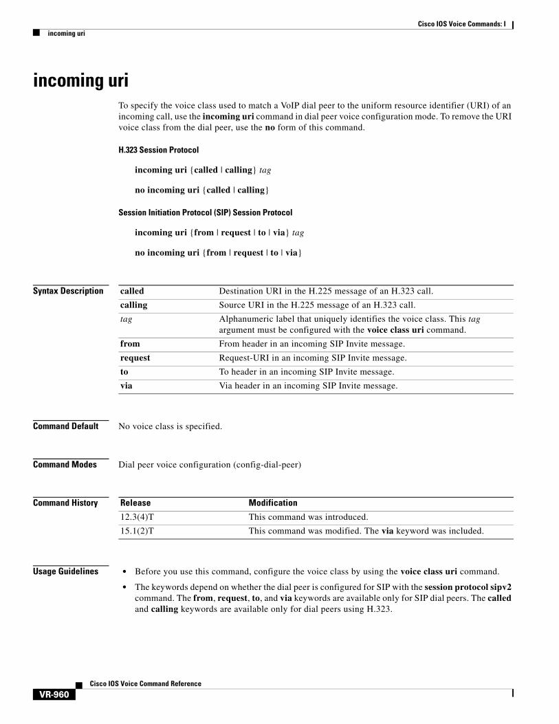
incoming uriTo specify the voice class used to match a VoIP dial peer to the uniform resource identifier (URI) of an incoming call, use the incoming uri command in dial peer voice configuration mode. To remove the URI voice class from the dial peer, use the no form of this command.
H.323 Session Protocol
incoming uri {called | calling} tag
no incoming uri {called | calling}
Session Initiation Protocol (SIP) Session Protocol
incoming uri {from | request | to | via} tag
no incoming uri {from | request | to | via}
Syntax Description
Command Default No voice class is specified.
Command Modes Dial peer voice configuration (config-dial-peer)
Command History
Usage Guidelines • Before you use this command, configure the voice class by using the voice class uri command.
• The keywords depend on whether the dial peer is configured for SIP with the session protocol sipv2 command. The from, request, to, and via keywords are available only for SIP dial peers. The called and calling keywords are available only for dial peers using H.323.
called Destination URI in the H.225 message of an H.323 call.
calling Source URI in the H.225 message of an H.323 call.
tag Alphanumeric label that uniquely identifies the voice class. This tag argument must be configured with the voice class uri command.
from From header in an incoming SIP Invite message.
request Request-URI in an incoming SIP Invite message.
to To header in an incoming SIP Invite message.
via Via header in an incoming SIP Invite message.
Release Modification
12.3(4)T This command was introduced.
15.1(2)T This command was modified. The via keyword was included.

Cisco IOS Voice Commands: Iincoming uri
VR-961Cisco IOS Voice Command Reference
• This command applies rules for dial peer matching. Table 29 and Table 30 show the rules and the order in which they are applied when the incoming uri command is used. The gateway compares the dial-peer command to the call parameter in its search to match an inbound call to a dial peer. All dial peers are searched based on the first match criterion. Only if no match is found does the gateway move on to the next criterion.
Note Calls using an E.164 number, rather than a URI, use the dial-peer matching rules that existed prior to Cisco IOS Release 15.1(2)T. For information, see theDial Peer Configuration on Voice Gateway Routers document, Cisco IOS Voice Configuration Library.
• You can use this command multiple times in the same dial peer with different keywords. For example, you can use incoming uri called and incoming uri calling in the same dial peer. The gateway then selects the dial peer based on the matching rules described in Table 29 and Table 30.
Examples The following example matches on the destination telephone URI in incoming H.323 calls by using the ab100 voice class:
dial-peer voice 100 voip incoming uri called ab100
Table 29 Dial-Peer Matching Rules for Inbound URI in SIP Calls
Match Order Cisco IOS Command Incoming Call Parameter
1 incoming uri via Via URI
2 incoming uri request Request-URI
3 incoming uri to To URI
4 incoming uri from From URI
5 incoming called-number Called number
6 answer-address Calling number
7 destination-pattern Calling number
8 carrier-id source Carrier-ID associated with the call
Table 30 Dial-Peer Matching Rules for Inbound URI in H.323 Calls
Match Order Cisco IOS Command Incoming Call Parameter
1 incoming uri called Destination URI in H.225 message
2 incoming uri calling Source URI in H.225 message
3 incoming called-number Called number
4 answer-address Calling number
5 destination-pattern Calling number
6 carrier-id source Source carrier-ID associated with the call
Cisco IOS Voice Commands: Iincoming uri
VR-962Cisco IOS Voice Command Reference
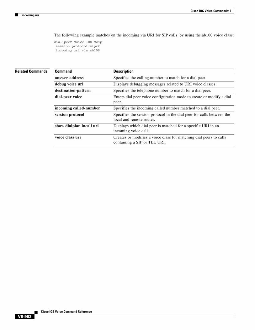
The following example matches on the incoming via URI for SIP calls by using the ab100 voice class:
dial-peer voice 100 voip session protocol sipv2incoming uri via ab100
Related Commands Command Description
answer-address Specifies the calling number to match for a dial peer.
debug voice uri Displays debugging messages related to URI voice classes.
destination-pattern Specifies the telephone number to match for a dial peer.
dial-peer voice Enters dial peer voice configuration mode to create or modify a dial peer.
incoming called-number Specifies the incoming called number matched to a dial peer.
session protocol Specifies the session protocol in the dial peer for calls between the local and remote router.
show dialplan incall uri Displays which dial peer is matched for a specific URI in an incoming voice call.
voice class uri Creates or modifies a voice class for matching dial peers to calls containing a SIP or TEL URI.
Cisco IOS Voice Commands: Iindex (voice class)
VR-963Cisco IOS Voice Command Reference
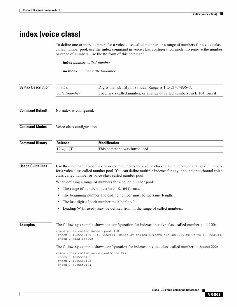
index (voice class)To define one or more numbers for a voice class called number, or a range of numbers for a voice class called number pool, use the index command in voice class configuration mode. To remove the number or range of numbers, use the no form of this command.
index number called-number
no index number called-number
Syntax Description
Command Default No index is configured.
Command Modes Voice class configuration
Command History
Usage Guidelines Use this command to define one or more numbers for a voice class called number, or a range of numbers for a voice class called number pool. You can define multiple indexes for any inbound or outbound voice class called number or voice class called number pool.
When defining a range of numbers for a called number pool:
• The range of numbers must be in E.164 format.
• The beginning number and ending number must be the same length.
• The last digit of each number must be 0 to 9.
• Leading '+' (if used) must be defined from in the range of called numbers.
Examples The following example shows the configuration for indexes in voice class called number pool 100:
voice class called number pool 100 index 1 4085550100 - 4085550111 (Range of called numbers are 4085550100 up to 4085550111) index 2 +3227045000
The following example shows configuration for indexes in voice class called number outbound 222:
voice class called number outbound 222index 1 4085550101index 2 4085550102index 2 4085550103
number Digits that identify this index. Range is 1 to 2147483647.
called-number Specifies a called number, or a range of called numbers, in E.164 format.
Release Modification
12.4(11)T This command was introduced.
Cisco IOS Voice Commands: Iindex (voice class)
VR-964Cisco IOS Voice Command Reference
Related Commands Command Description
voice class called number
One or more called numbers configured for a voice class.

Cisco IOS Voice Commands: Iinfo-digits
VR-965Cisco IOS Voice Command Reference
info-digitsTo automatically prepend two information digits to the beginning of a dialed number associated with the given POTS dial peer, use the info-digits command in dial-peer configuration mode. To prepend the info-digits with “00” use the default info-digits form of this command. To keep the router from automatically prepending the two-digit information numbers to the beginning of the POTS dial peer, use the no form of this command.
info-digits xx
default info-digits
no info-digits
Syntax Description
Defaults The dialed number is prepended with “00”, indicating that the dialed number is a regular line.
Command Modes Dial-peer configuration
Command History
xx Specifies the two-digit prefix that the router will automatically prepend to the dialed number for the given POTS dial peer to identify the origin of the call. This value cannot contain any more or less than two digits. Valid values include:
• 00—Regular line
• 01—4- and 8-party
• 06—Hotel or Motel
• 07—Coinless
• 10—Test call
• 27—Coin
• 95—Test call
Note Values 12 through 19 cannot be assigned because of conflicts with international 20 Automatic Identification of Outward listed directory number sent.
Release Modification
12.2(1)T This command was introduced.
12.3(7)T This command was modified. The default behavior was changed to prepend the dialed number the with “00”.

Cisco IOS Voice Commands: Iinfo-digits
VR-966Cisco IOS Voice Command Reference
Usage Guidelines This command is designed to prepend a pair of information digits to the beginning of the dialed number string for the POTS dial peer that will enable you to dynamically redirect the outgoing call. The info-digits command is only available for POTS dial peers tied to a voice-port that corresponds to Feature Group-D (FGD) Exchange Access North American (EANA) signaling that provides specific call services such as emergency 911 calls in the United States. Configuring the info-digit command for other voice-port types is not advised and may yield undesirable results.
Examples The following example prepends the information number string 91 to the beginning of the dialed number for POTS dial peer 10:
dial-peer voice 10 potsinfo-digits 91
Cisco IOS Voice Commands: Iinformation-type
VR-967Cisco IOS Voice Command Reference
information-typeTo select a specific information type for a Voice over IP (VoIP) or plain old telephone service (POTS) dial peer, use the information-type command in dial peer configuration mode. To remove the current information type setting, use the no form of this command. To return to the default configuration, use the no form of this command.
information-type {fax | voice | video}
no information-type
Syntax Description
Command Default Voice
Command Modes Dial peer configuration
Command History
Usage Guidelines The fax keyword applies to both on-ramp and off-ramp store-and-forward fax functions.
Examples The following example shows the configuration for information type fax for VoIP dial peer 10:
dial-peer voice 10 voipinformation-type fax
The following example shows the configuration for information type video for POTS dial peer 22:
dial-peer voice 22 potsinformation-type video
fax The information type is set to store-and-forward fax.
voice The information type is set to voice. This is the default.
video The information type is set to video.
Release Modification
11.3(1)T This command was introduced on the Cisco 3600 series.
12.0(4)XJ This command was modified for store-and-forward fax.
12.0(4)T This command was integrated into Cisco IOS Release 12.0(4)T.
12.1(1)T This command was integrated into Cisco IOS Release 12.1(1)T.
12.1(5)T This command was integrated into Cisco IOS Release 12.1(5)T.
12.2(4)T This command was implemented on the Cisco 1750.
12.2(8)T This command was implemented on the following platforms: Cisco 1751, Cisco 2600 series, Cisco 3600 series, Cisco 3725, and Cisco 3745.
12.4(11)T The video keyword was added.

Cisco IOS Voice Commands: Iinformation-type
VR-968Cisco IOS Voice Command Reference
Related Commands Command Description
isdn integrate calltype all
Enables integrated mode (for data, voice, and video) on ISDN BRI or PRI interfaces.
Cisco IOS Voice Commands: Iinject guard-tone
VR-969Cisco IOS Voice Command Reference
inject guard-toneTo play out a guard tone with the voice packet, use the inject guard-tone command in voice-class configuration mode. To remove the guard tone, use the no form of this command.
inject guard-tone frequency amplitude [idle]
no inject guard-tone frequency amplitude [idle]
Syntax Description
Command Default No guard tone is injected.
Command Modes Voice-class configuration
Command History
Usage Guidelines The inject guard-tone command has an effect on an ear and mouth (E&M) analog or digital voice port only if the signal type for that port is Land Mobile Radio (LMR). The guard tone is played out with the voice packet to keep the radio channel up. Guard tones of 1950 Hz and 2175 Hz can be filtered out before the voice packet is sent from the digital signal processor (DSP) to the network using the digital-filter command.
Examples The following example configures a guard tone of 1950 Hz and –10 dBm to be played out with voice packets:
voice class tone-signal tone1 inject guard-tone 2175 -30
Related Commands
frequency Frequency, in Hz, of the tone to be injected. Range is integers from 1 to 4000.
amplitude Amplitude, in dBm, of the tone to be injected. Range is integers from –50 to –3.
idle (Optional) Play out the inverse of the guard tone when there are no voice packets. Idle tone and guard tone are mutually exclusive.
Release Modification
12.3(4)XD This command was introduced.
12.3(7)T This command was integrated into Cisco IOS Release 12.3(7)T.
Command Description
digital-filter Specifies the digital filter to be used before the voice packet is sent from the DSP to the network.

Cisco IOS Voice Commands: Iinject pause
VR-970Cisco IOS Voice Command Reference
inject pauseTo specify a pause between injected tones, use the inject pause command in voice-class configuration mode. To remove the pause, use the no form of this command.
inject pause index milliseconds
no inject pause index milliseconds
Syntax Description
Command Default milliseconds: 0 milliseconds
Command Modes Voice-class configuration
Command History
Usage Guidelines The inject pause command has an effect on an ear and mouth (E&M) voice port only if the signal type for that port is Land Mobile Radio (LMR). Use this command to specify the pause between injected tones specified with the inject tone command. Use the index argument of this command in conjunction with the index argument of the inject tone command to specify the order of the pauses and tones.
Examples The following example configures a pause of 100 milliseconds after the injected tone:
voice class tone-signal 100 inject tone 1 2000 0 200 inject pause 2 100
Related Commands
index Order of pauses and tones. Range is integers from 1 to 10.
milliseconds Duration, in milliseconds, of the pause between injected tones. Range is integers from 10 to 500.
Release Modification
12.3(4)XD This command was introduced.
12.3(7)T This command was integrated into Cisco IOS Release 12.3(7)T.
Command Description
inject tone Specifies a wakeup or frequency selection tone to be played out before the voice packet.
Cisco IOS Voice Commands: Iinject tone
VR-971Cisco IOS Voice Command Reference
inject toneTo specify a wakeup or frequency selection tone to be played out before the voice packet, use the inject tone command in voice-class configuration mode. To remove the tone, use the no form of this command.
inject tone index frequency amplitude duration
no inject tone index frequency amplitude duration
Syntax Description
Command Default No tone is injected.
Command Modes Voice-class configuration
Command History
Usage Guidelines The inject tone command has an effect on an ear and mouth (E&M) voice port only if the signal type for that port is Land Mobile Radio (LMR). Use this command with the inject pause command to configure wakeup and frequency selection tones. Use the index argument of this command in conjunction with the index argument of the inject pause command to specify the order of the pauses and tones.
If you configure injected tones with this command, be sure to use the timing delay-voice tdm command to configure a delay before the voice packet is played out. The delay must be equal to the sum of the durations of the injected tones and pauses in the tone-signal voice class.
Examples The following example configures a frequency selection tone to be played out before the voice packet:
voice class tone-signal 100 inject tone 1 1950 3 150 inject tone 2 2000 0 60 inject pause 3 60 inject tone 4 2175 3 150 inject tone 5 1000 0 50
index Order of pauses and tones. Range is integers from 1 to 10.
frequency Frequency, in Hz, of the tone to be injected. Range is integers from 1 to 4000.
amplitude Amplitude, in dBm, of the tone to be injected. Range is integers from –30 to 3.
duration Duration, in milliseconds, of the tone to be injected. Range is integers from 10 to 500.
Release Modification
12.3(4)XD This command was introduced.
12.3(7)T This command was integrated into Cisco IOS Release 12.3(7)T.
Cisco IOS Voice Commands: Iinject tone
VR-972Cisco IOS Voice Command Reference
Related Commands Command Description
inject pause Specifies a pause between injected tones.
timing delay-voice tdm Specifies the delay before a voice packet is played out.
Cisco IOS Voice Commands: Iinput gain
VR-973Cisco IOS Voice Command Reference
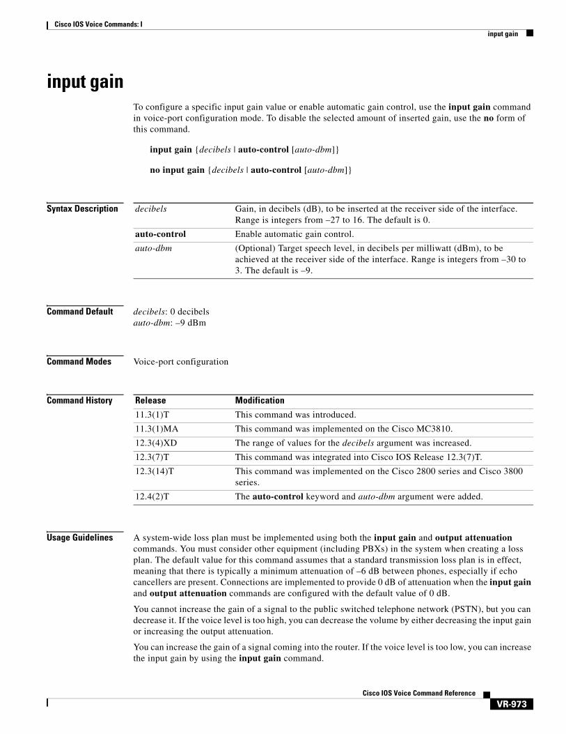
input gainTo configure a specific input gain value or enable automatic gain control, use the input gain command in voice-port configuration mode. To disable the selected amount of inserted gain, use the no form of this command.
input gain {decibels | auto-control [auto-dbm]}
no input gain {decibels | auto-control [auto-dbm]}
Syntax Description
Command Default decibels: 0 decibelsauto-dbm: –9 dBm
Command Modes Voice-port configuration
Command History
Usage Guidelines A system-wide loss plan must be implemented using both the input gain and output attenuation commands. You must consider other equipment (including PBXs) in the system when creating a loss plan. The default value for this command assumes that a standard transmission loss plan is in effect, meaning that there is typically a minimum attenuation of –6 dB between phones, especially if echo cancellers are present. Connections are implemented to provide 0 dB of attenuation when the input gain and output attenuation commands are configured with the default value of 0 dB.
You cannot increase the gain of a signal to the public switched telephone network (PSTN), but you can decrease it. If the voice level is too high, you can decrease the volume by either decreasing the input gain or increasing the output attenuation.
You can increase the gain of a signal coming into the router. If the voice level is too low, you can increase the input gain by using the input gain command.
decibels Gain, in decibels (dB), to be inserted at the receiver side of the interface. Range is integers from –27 to 16. The default is 0.
auto-control Enable automatic gain control.
auto-dbm (Optional) Target speech level, in decibels per milliwatt (dBm), to be achieved at the receiver side of the interface. Range is integers from –30 to 3. The default is –9.
Release Modification
11.3(1)T This command was introduced.
11.3(1)MA This command was implemented on the Cisco MC3810.
12.3(4)XD The range of values for the decibels argument was increased.
12.3(7)T This command was integrated into Cisco IOS Release 12.3(7)T.
12.3(14)T This command was implemented on the Cisco 2800 series and Cisco 3800 series.
12.4(2)T The auto-control keyword and auto-dbm argument were added.
Cisco IOS Voice Commands: Iinput gain
VR-974Cisco IOS Voice Command Reference
Typical Land Mobile Radio (LMR) signaling systems send 0 dB out and expect –10 dB in. Setting output attenuation to 10 dB is typical. Output attenuation should be adjusted to provide the voice level required by the radio to produce correct transmitter modulation.
The auto-control keyword and auto-dbm argument are available on an ear and mouth (E&M) voice port only if the signal type for that port is LMR. The auto-control keyword enables automatic gain control, which is performed by the digital signal processor (DSP). Automatic gain control adjusts speech to a comfortable volume when it becomes too loud or too soft. Because of radio network loss and other environmental factors, the speech level arriving at a router from an LMR system could be very low. You can use automatic gain control to ensure that the speech is played back at a more comfortable level. Because the gain is inserted digitally, the background noise can also be amplified. Automatic gain control is implemented as follows:
• Output level: –9 dB
• Gain range: –12 dB to 20 dB
• Attack time (low to high): 30 milliseconds
• Attack time (high to low): 8 seconds
Examples The following example inserts a 3-dB gain at the receiver side of the interface in the Cisco 3600 series router:
port 1/0/0input gain 3
Related Commands Command Description
output attenuation Configures a specific output attenuation value or enables automatic gain control for a voice port.
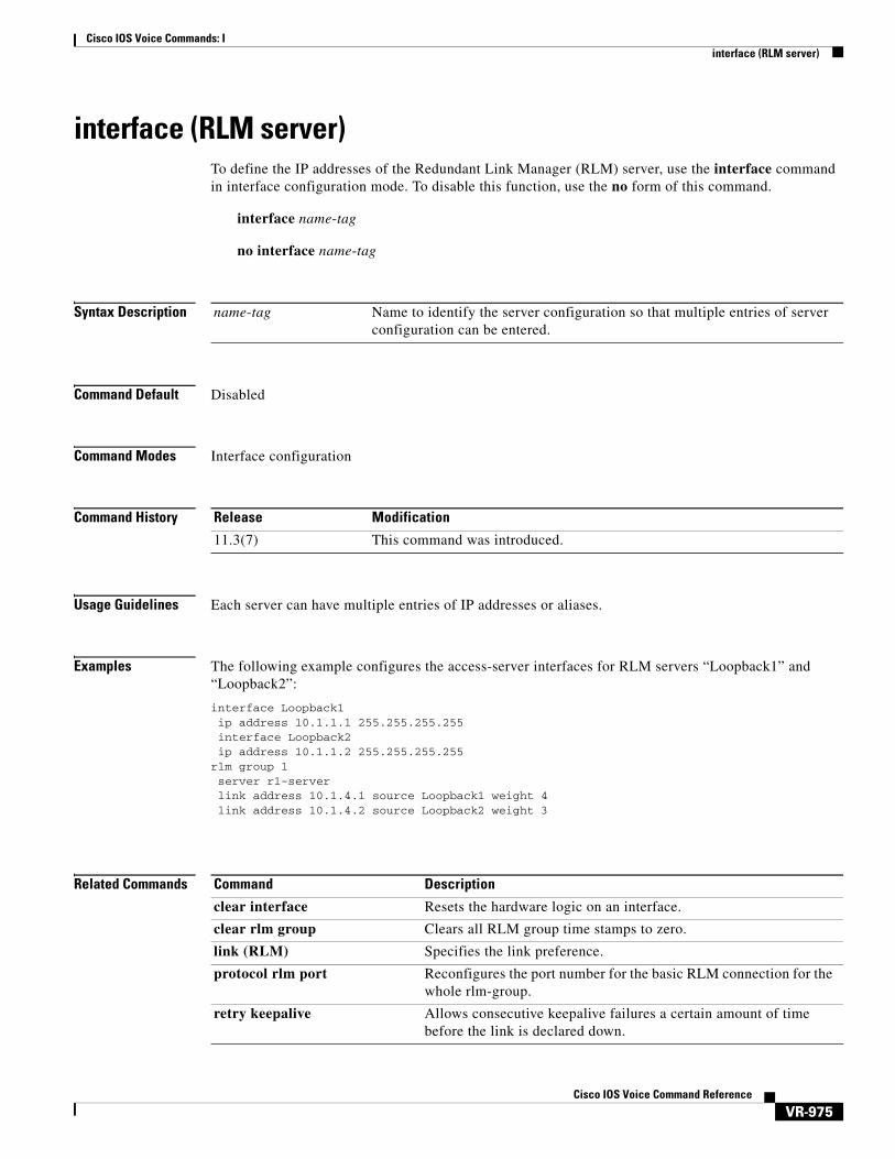
Cisco IOS Voice Commands: Iinterface (RLM server)
VR-975Cisco IOS Voice Command Reference
interface (RLM server)To define the IP addresses of the Redundant Link Manager (RLM) server, use the interface command in interface configuration mode. To disable this function, use the no form of this command.
interface name-tag
no interface name-tag
Syntax Description
Command Default Disabled
Command Modes Interface configuration
Command History
Usage Guidelines Each server can have multiple entries of IP addresses or aliases.
Examples The following example configures the access-server interfaces for RLM servers “Loopback1” and “Loopback2”:
interface Loopback1ip address 10.1.1.1 255.255.255.255interface Loopback2ip address 10.1.1.2 255.255.255.255
rlm group 1server r1-serverlink address 10.1.4.1 source Loopback1 weight 4link address 10.1.4.2 source Loopback2 weight 3
Related Commands
name-tag Name to identify the server configuration so that multiple entries of server configuration can be entered.
Release Modification
11.3(7) This command was introduced.
Command Description
clear interface Resets the hardware logic on an interface.
clear rlm group Clears all RLM group time stamps to zero.
link (RLM) Specifies the link preference.
protocol rlm port Reconfigures the port number for the basic RLM connection for the whole rlm-group.
retry keepalive Allows consecutive keepalive failures a certain amount of time before the link is declared down.

Cisco IOS Voice Commands: Iinterface (RLM server)
VR-976Cisco IOS Voice Command Reference
server (RLM) Defines the IP addresses of the server.
show rlm group statistics Displays the network latency of the RLM group.
show rlm group status Displays the status of the RLM group.
show rlm group timer Displays the current RLM group timer values.
shutdown (RLM) Shuts down all of the links under the RLM group.
timer Overwrites the default setting of timeout values.
Command Description
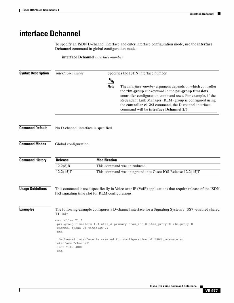
Cisco IOS Voice Commands: Iinterface Dchannel
VR-977Cisco IOS Voice Command Reference
interface DchannelTo specify an ISDN D-channel interface and enter interface configuration mode, use the interface Dchannel command in global configuration mode.
interface Dchannel interface-number
Syntax Description
Command Default No D-channel interface is specified.
Command Modes Global configuration
Command History
Usage Guidelines This command is used specifically in Voice over IP (VoIP) applications that require release of the ISDN PRI signaling time slot for RLM configurations.
Examples The following example configures a D-channel interface for a Signaling System 7 (SS7)-enabled shared T1 link:
controller T1 1pri-group timeslots 1-3 nfas_d primary nfas_int 0 nfas_group 0 rlm-group 0 channel group 23 timeslot 24end
! D-channel interface is created for configuration of ISDN parameters:interface Dchannel1isdn T309 4000end
interface-number Specifies the ISDN interface number.
Note The interface-number argument depends on which controller the rlm-group subkeyword in the pri-group timeslots controller configuration command uses. For example, if the Redundant Link Manager (RLM) group is configured using the controller e1 2/3 command, the D-channel interface command will be interface Dchannel 2/3.
Release Modification
12.2(8)B This command was introduced.
12.2(15)T This command was integrated into Cisco IOS Release 12.2(15)T.

Cisco IOS Voice Commands: Iinterface Dchannel
VR-978Cisco IOS Voice Command Reference
Related Commands Command Description
pri-group timeslots Specifies an ISDN PRI group on a channelized T1 or E1 controller, and releases the ISDN PRI signaling time slot for environments that require that SS7-enabled VoIP applications share all slots in a PRI group.

Cisco IOS Voice Commands: Iinterface event-log dump ftp
VR-979Cisco IOS Voice Command Reference
interface event-log dump ftpTo enable the gateway to write the contents of the interface event log buffer to an external file, use the interface event-log dump ftp command in application configuration monitor mode. To reset to the default, use the no form of this command.
interface event-log dump ftp server[:port]/file username username password [encryption-type] password
no interface event-log dump ftp server[:port]/file username username password [encryption-type] password
Syntax Description
Command Default Interface event log buffer is not written to an external file.
Command Modes Application configuration monitor
Command History
server Name or IP address of FTP server where the file is located.
port (Optional) Specific port number on server.
file Name and path of file.
username Username required to access file.
encryption-type (Optional) The Cisco proprietary algorithm used to encrypt the password. Values are 0 or 7. To disable encryption enter 0; to enable encryption enter 7. If you specify 7, you must enter an encrypted password (a password already encrypted by a Cisco router).
password Password required to access file.
Release Modification
12.3(14)T This command was introduced to replace the call application interface event-log dump ftp command.

Cisco IOS Voice Commands: Iinterface event-log dump ftp
VR-980Cisco IOS Voice Command Reference
Usage Guidelines This command enables the gateway to automatically write the interface event log buffer to the named file when the buffer becomes full. The default buffer size is 4 KB. To modify the size of the buffer, use the interface event-log max-buffer-size command. To manually flush the event log buffer, use the interface dump event-log command in privileged EXEC mode.
Note • Enabling the gateway to write event logs to FTP could adversely impact gateway memory resources in some scenarios, for example, when:
• The gateway is consuming high processor resources and FTP does not have enough processor resources to flush the logged buffers to the FTP server.
• The designated FTP server is not powerful enough to perform FTP transfers quickly
• Bandwidth on the link between the gateway and the FTP server is not large enough
• The gateway is receiving a high volume of short-duration calls or calls that are failing
You should enable FTP dumping only when necessary and not enable it in situations where it might adversely impact system performance.
Examples The following example specifies that interface event log are written to an external file named int_elogs.log on a server named ftp-server:
applicationmonitorinterface event-log dump ftp ftp-server/elogs/int_elogs.log username myname password 0 mypass
The following example specifies that application event logs are written to an external file named int_elogs.log on a server with the IP address of 10.10.10.101:
applicationmonitorinterface event-log dump ftp 10.10.10.101/elogs/int_elogs.log username myname password 0 mypass
Related Commands Command Description
call application interface event-log dump ftp
Enable the gateway to write the contents of the interface event log buffer to an external file.
interface dump event-log Flushes the event log buffer for application interfaces to an external file.
interface event-log Enables event logging for external interfaces used by voice applications.
interface event-log max-buffer-size
Sets the maximum size of the event log buffer for each application interface.
interface max-server-records
Sets the maximum number of application interface records that are saved.
show call application interface
Displays event logs and statistics for application interfaces.

Cisco IOS Voice Commands: Iinterface event-log error only
VR-981Cisco IOS Voice Command Reference
interface event-log error onlyTo restrict event logging to error events only for application interfaces, use the interface event-log error-only command in application configuration monitor mode. To reset to the default, use the no form of this command.
interface event-log error-only
no interface event-log error-only
Syntax Description This command has no arguments or keywords.
Command Default All events are logged.
Command Modes Application configuration monitor
Command History
Usage Guidelines This command limits the severity level of the events that are logged; it does not enable logging. You must use this command with the interface event-log command, which enables event logging for all application interfaces.
Examples The following example enables event logging for error events only:
applicationmonitorinterface event-log error-only
Related Commands
Release Modification
12.3(14)T This command was introduced to replace the call application interface event-log error only command.
Command Description
call application interface event-log error-only
Restricts event logging to error events only for application interfaces.
interface event-log Enables event logging for external interfaces used by voice applications.
interface event-log max-buffer-size
Sets the maximum size of the event log buffer for each application interface.
interface max-server-records
Sets the maximum number of application interface records that are saved.
show call application interface
Displays event logs and statistics for application interfaces.

Cisco IOS Voice Commands: Iinterface event-log max-buffer-size
VR-982Cisco IOS Voice Command Reference
interface event-log max-buffer-sizeTo set the maximum size of the event log buffer for each application interface, use the interface event-log max-buffer-size command in application configuration monitor mode. To reset to the default, use the no form of this command.
interface event-log max-buffer-size kbytes
no interface event-log max-buffer-size
Syntax Description
Command Default 4 KB
Command Modes Application configuration monitor
Command History
Usage Guidelines If the event log buffer reaches the limit set by this command, the gateway allocates a second buffer of equal size. The contents of both buffers is displayed when you use the show call application interface command. When the first event log buffer becomes full, the gateway automatically appends its contents to an external FTP location if the interface event-log dump ftp command is used.
A maximum of two buffers are allocated for an event log. If both buffers are filled, the first buffer is deleted and another buffer is allocated for new events (buffer wraps around). If the interface event-log dump ftp command is configured and the second buffer becomes full before the first buffer is dumped, event messages are dropped and are not recorded in the buffer.
Examples The following example sets the maximum buffer size to 8 KB:
applicationmonitorinterface event-log max-buffer-size 8
Related Commands
kbytes Maximum buffer size, in kilobytes. Range is 1 to 10. Default is 4.
Release Modification
12.3(14)T This command was introduced to replace the call application interface event-log max-buffer-size command.
Command Description
call application interface event-log max-buffer-size
Sets the maximum size of the event log buffer for each application interface.
interface dump event-log Flushes the event log buffer for application interfaces to an external file.
interface event-log dump ftp
Enables the gateway to write the contents of the interface event log buffer to an external file.

Cisco IOS Voice Commands: Iinterface event-log max-buffer-size
VR-983Cisco IOS Voice Command Reference
interface max-server-records
Sets the maximum number of application interface records that are saved.
show call application interface
Displays event logs and statistics for application interfaces.
Command Description

Cisco IOS Voice Commands: Iinterface max-server-records
VR-984Cisco IOS Voice Command Reference
interface max-server-recordsTo set the maximum number of application interface records that are saved, use the interface max-server-records command in application configuration monitor mode. To reset to the default, use the no form of this command.
interface max-server-records number
no interface max-server-records
Syntax Description
Command Default 10
Command Modes Application configuration monitor
Command History
Usage Guidelines Only the specified number of records from the most recently accessed servers are kept.
Examples The following example sets the maximum saved records to 50:
applicationmonitorinterface max-server-records 50
Related Commands
number Maximum number of records to save. Range is 1 to 100. Default is 10.
Release Modification
12.3(14)T This command was introduced to replace the call application interface max-server-records command.
Command Description
call application interface max-server-records
Sets the maximum number of application interface records that are saved.
interface event-log Enables event logging for external interfaces used by voice applications.
interface event-log max-buffer-size
Sets the maximum size of the event log buffer for each application interface.
show call application interface
Displays event logs and statistics for application interfaces.
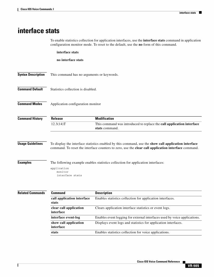
Cisco IOS Voice Commands: Iinterface stats
VR-985Cisco IOS Voice Command Reference
interface statsTo enable statistics collection for application interfaces, use the interface stats command in application configuration monitor mode. To reset to the default, use the no form of this command.
interface stats
no interface stats
Syntax Description This command has no arguments or keywords.
Command Default Statistics collection is disabled.
Command Modes Application configuration monitor
Command History
Usage Guidelines To display the interface statistics enabled by this command, use the show call application interface command. To reset the interface counters to zero, use the clear call application interface command.
Examples The following example enables statistics collection for application interfaces:
applicationmonitorinterface stats
Related Commands
Release Modification
12.3(14)T This command was introduced to replace the call application interface stats command.
Command Description
call application interface stats
Enables statistics collection for application interfaces.
clear call application interface
Clears application interface statistics or event logs.
interface event-log Enables event logging for external interfaces used by voice applications.
show call application interface
Displays event logs and statistics for application interfaces.
stats Enables statistics collection for voice applications.

Cisco IOS Voice Commands: Iip circuit
VR-986Cisco IOS Voice Command Reference
ip circuitTo create carrier IDs on an IP virtual trunk group, and create a maximum capacity for the IP group, use the ip circuit command. To remove a trunk group or maximum capacity, use the no form of the command.
ip circuit {carrier-id carrier-name [reserved-calls reserved] | max-calls maximum-calls | default {only | name carrier-name}}
no ip circuit {carrier-id carrier-name | default {only | name carrier-name}}
Syntax Description
Command Default If this command is not specified, no IP carriers and no maximum call leg values are defined.
Command Modes H.323 configuration.
Command History
Usage Guidelines You can use the ip circuit command only when no calls are active. You can define multiple carrier IDs, and the ordering does not matter. IP circuit default only is mutually exclusive with defining carriers with circuit carrier id.
If ip circuit default only is specified, the maximum calls value is set to 1000.
Examples The following example specifies a default circuit and maximum number of calls:
voice service voip no allow-connections any to pots no allow-connections pots to any allow-connections h323 to h323 h323
ip circuit max-calls 1000ip circuit default only
The following example specifies a default carrier and incoming source carrier:
carrier-id Sets the IP circuit associated with a specific carrier.
carrier-name Defines an IP circuit using the specified name as the circuit ID.
reserved-calls reserved (Optional) Specifies the maximum number of calls for the circuit ID. Default value is 200.
max-calls maximum-calls Sets the number of maximum aggregate H.323 IP circuit carrier call legs. Default value is 1000.
default only Creates a single carrier using the default carrier name.
default name Changes the default circuit name.
carrier-name Default carrier name.
Release Modification
12.2(13)T3 This command was introduced.

Cisco IOS Voice Commands: Iip circuit
VR-987Cisco IOS Voice Command Reference
voice service voip no allow-connections any to pots no allow-connections pots to any allow-connections h323 to h323 h323 ip circuit carrier-id AA reserved-calls 200
ip circuit max-calls 1000
Related Commands Command Description
show crm Displays some of the values set by this command.
voice-source group Assigns a name to a set of source IP group characteristics, which are used to identify and translate an incoming VoIP call.

Cisco IOS Voice Commands: Iip dhcp-client forcerenew
VR-988Cisco IOS Voice Command Reference
ip dhcp-client forcerenewTo enable forcerenew-message handling on the DHCP client when authentication is enabled, use the ip dhcp-client forcerenew command in global configuration mode. To disable the forced authentication, use the no form of this command.
ip dhcp-client forcerenew
no ip dhcp-client forcerenew
Syntax Description This command has no arguments or keywords.
Command Default Forcerenew messages are dropped.
Command Modes Global configuration (config)
Command History
Usage Guidelines DHCP forcerenew handling is not enabled until the CLI is configured.
Examples The following example shows how to enable DHCP forcerenew-message handling on the DHCP client:
Router(config)# ip dhcp-client forcerenew
Related Commands
Release Modification
12.4(22)YB This command was introduced.
15.0(1)M This command was integrated into Cisco IOS Release 15.0(1)M.
Command Description
ip dhcp client authentication key-chain
Specifies the key chain to be used in DHCP authentication requests.
ip dhcp client authentication mode
Specifies the type of authentication to be used in DHCP messages on the interface.
key chain Identifies a group of authentication keys for routing protocols.
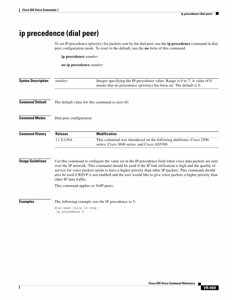
Cisco IOS Voice Commands: Iip precedence (dial peer)
VR-989Cisco IOS Voice Command Reference
ip precedence (dial peer)To set IP precedence (priority) for packets sent by the dial peer, use the ip precedence command in dial peer configuration mode. To reset to the default, use the no form of this command.
ip precedence number
no ip precedence number
Syntax Description
Command Default The default value for this command is zero (0)
Command Modes Dial peer configuration
Command History
Usage Guidelines Use this command to configure the value set in the IP precedence field when voice data packets are sent over the IP network. This command should be used if the IP link utilization is high and the quality of service for voice packets needs to have a higher priority than other IP packets. This command should also be used if RSVP is not enabled and the user would like to give voice packets a higher priority than other IP data traffic.
This command applies to VoIP peers.
Examples The following example sets the IP precedence to 5:
dial-peer voice 10 voipip precedence 5
number Integer specifying the IP precedence value. Range is 0 to 7. A value of 0 means that no precedence (priority) has been set. The default is 0.
Release Modification
11.3(1)NA This command was introduced on the following platforms: Cisco 2500 series, Cisco 3600 series, and Cisco AS5300.
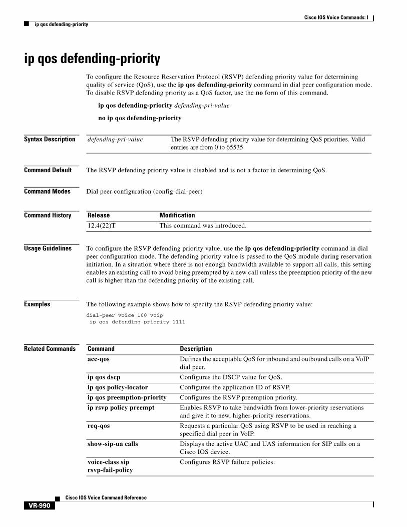
Cisco IOS Voice Commands: Iip qos defending-priority
VR-990Cisco IOS Voice Command Reference
ip qos defending-priorityTo configure the Resource Reservation Protocol (RSVP) defending priority value for determining quality of service (QoS), use the ip qos defending-priority command in dial peer configuration mode. To disable RSVP defending priority as a QoS factor, use the no form of this command.
ip qos defending-priority defending-pri-value
no ip qos defending-priority
Syntax Description
Command Default The RSVP defending priority value is disabled and is not a factor in determining QoS.
Command Modes Dial peer configuration (config-dial-peer)
Command History
Usage Guidelines To configure the RSVP defending priority value, use the ip qos defending-priority command in dial peer configuration mode. The defending priority value is passed to the QoS module during reservation initiation. In a situation where there is not enough bandwidth available to support all calls, this setting enables an existing call to avoid being preempted by a new call unless the preemption priority of the new call is higher than the defending priority of the existing call.
Examples The following example shows how to specify the RSVP defending priority value:
dial-peer voice 100 voipip qos defending-priority 1111
Related Commands
defending-pri-value The RSVP defending priority value for determining QoS priorities. Valid entries are from 0 to 65535.
Release Modification
12.4(22)T This command was introduced.
Command Description
acc-qos Defines the acceptable QoS for inbound and outbound calls on a VoIP dial peer.
ip qos dscp Configures the DSCP value for QoS.
ip qos policy-locator Configures the application ID of RSVP.
ip qos preemption-priority Configures the RSVP preemption priority.
ip rsvp policy preempt Enables RSVP to take bandwidth from lower-priority reservations and give it to new, higher-priority reservations.
req-qos Requests a particular QoS using RSVP to be used in reaching a specified dial peer in VoIP.
show-sip-ua calls Displays the active UAC and UAS information for SIP calls on a Cisco IOS device.
voice-class sip rsvp-fail-policy
Configures RSVP failure policies.

Cisco IOS Voice Commands: Iip qos dscp
VR-991Cisco IOS Voice Command Reference
ip qos dscpTo configure the differentiated services code point (DSCP) value for quality of service (QoS), use the ip qos dscp command in dial peer configuration mode. To disable DSCP as a QoS factor, set the DSCP value to default (which sets the value to the 000000 bit pattern). To set DSCP values to their default settings, use the no form of this command.
ip qos dscp {dscp-value | set-af | set-cs | default | ef} {signaling | media [rsvp-pass | rsvp-fail] | video [rsvp-none | rsvp-pass | rsvp-fail]}
no ip qos dscp {dscp-value | set-af | set-cs | default | ef} {signaling | media [rsvp-pass | rsvp-fail] | video [rsvp-none | rsvp-pass | rsvp-fail]}
Syntax Description
Command Default The DSCP default values are as follows:• The default DSCP value for all signaling packets is af31.
• The default DSCP value for all media (voice and fax) packets is ef.• The default DSCP value for all video packets is af41.
dscp-value DSCP value. Valid entries are from 0 to 63.
set-af An assured forwarding bit pattern as the DSCP value:
• af11—bit pattern 001010• af12—bit pattern 001100• af13—bit pattern 001110• af21—bit pattern 010010• af22—bit pattern 010100• af23—bit pattern 010110
• af31—bit pattern 011010• af32—bit pattern 011100• af33—bit pattern 011110• af41—bit pattern 100010• af42—bit pattern 100100• af43—bit pattern 100110
set-cs Class-selector code point as the DSCP value:
• cs1—code point 1 (precedence 1)• cs2—code point 2 (precedence 2)• cs3—code point 3 (precedence 3)• cs4—code point 4 (precedence 4)
• cs5—code point 5 (precedence 5)• cs6—code point 6 (precedence 6)• cs7—code point 7 (precedence 7)
default Specifies the default bit pattern 000000 as the DSCP value.
ef Specifies the expedited forwarding bit pattern 101110 as the DSCP value.
signaling Specifies that the DSCP value applies to signaling packets.
media Specifies that the DSCP value applies to media packets (voice and fax).
rsvp-pass (Optional) Specifies that the DSCP value applies to packets with successful Resource Reservation Protocol (RSVP) reservations.
rsvp-fail (Optional) Specifies that the DSCP value applies to packets (media or video) with failed RSVP reservations.
video Specifies that the DSCP value applies to video packets. This option is valid only for Cisco Unified Communications Manager Express (Cisco Unified CME) on a Cisco Unified Border Element.
rsvp-none (Optional) Specifies that the DSCP value applies to video packets with no RSVP reservations (valid only for video packets.)
Cisco IOS Voice Commands: Iip qos dscp
VR-992Cisco IOS Voice Command Reference
Command Modes Dial peer configuration (config-dial-peer)
Command History
Usage Guidelines To configure voice, signaling, and video traffic priorities, use the ip qos dscp command in dial peer configuration mode. The recommended value for media (voice and fax) packets is ef; for signaling packets, the recommended value is af31; and for video packets, it is af41 (all defaults).
Additionally, before you can specify RSVP QoS, you must first use the ip rsvp bandwidth command to enable RSVP on the IP interface.
Examples The following example shows how to set the DSCP value to a class-selector code point value of 1 and apply that DSCP setting to media (voice and fax) payload packets with no RSVP configured:
dial-peer voice 1 voip ip qos dscp cs1 media
The following example shows how to set the DSCP value to the expedited forwarding bit pattern and apply that DSCP setting to media (voice and fax) payload packets with a successful RSVP connection:
dial-peer voice 1 voipip qos dscp ef media rsvp-pass
The following example shows how to set the DSCP value to an assured forwarding code point value of 22 and apply that DSCP setting to all signaling packets:
dial-peer voice 1 voipip qos dscp af22 signaling
The following example shows how to set the DSCP value to an assured forwarding code point value of 43 and apply that DSCP setting to video packets with a successful RSVP connection:
dial-peer voice 100 voipip qos dscp af43 video rsvp-pass
Related Commands
Release Modification
12.2(2)T This command was introduced. It replaced the ip precedence (dial peer) command
12.3(4)T Keywords were added to support DSCP configuration for video streams.
12.4(22)T Keywords were added to apply a DSCP value to media (voice and fax) packets with a specified (successful or failed) RSVP connection.
Command Description
call rsvp-sync Enables synchronization between RSVP signaling and the voice signaling protocol.
ip qos defending-priority Configures the RSVP defending priority value.
ip qos policy-locator Configures the application ID of RSVP.
ip qos preemption-priority Configures the RSVP preemption priority value.

Cisco IOS Voice Commands: Iip qos dscp
VR-993Cisco IOS Voice Command Reference
ip rsvp bandwidth Enables RSVP for IP on an interface.
ip rsvp signalling dscp Configures the DSCP settings to be used on RSVP messages on an interface.
Command Description
Cisco IOS Voice Commands: Iip qos policy-locator
VR-994Cisco IOS Voice Command Reference
ip qos policy-locatorTo configure a quality of service (QoS) policy-locator (application ID) used to deploy Resource Reservation Protocol (RSVP) policies for specifying bandwidth reservations on Cisco IOS Session Initiation Protocol (SIP) devices, use the ip qos policy-locator command in dial peer configuration mode. To delete an application policy, use the no form of this command.
ip qos policy-locator {video | voice} [app app-string] [guid guid-string] [sapp subapp-string] [ver version-string]
no ip qos policy-locator {video | voice} [app app-string] [guid guid-string] [sapp subapp-string] [ver version-string]
Syntax Description
Command Default No policy is specified.
Command Modes Dial peer configuration (config-dial-peer)
Command History
Usage Guidelines In Cisco IOS software, the RSVP can process and accept requests by referring to multiple bandwidth pools. To enhance the granularity of local policy match criteria on Cisco IOS SIP devices, bandwidth pools can include policies based on application IDs. You can use these application-specific IDs to reserve bandwidth for each until specified bandwidth limits are reached.
To prevent one application type from consuming all bandwidth, RFC 2872, Application and Sub Application Identity Policy Element for Use with RSVP, allows for the creation of separate bandwidth reservation pools. For example, an RSVP reservation pool can be created for voice traffic and another for video traffic so that reservations tagged with these application IDs can then be matched to the interface bandwidth pools using RSVP local policies. To limit bandwidth per application, though, you must configure a bandwidth limit for each application and configure each with a reservation flag that associates the application with the appropriate bandwidth limit.
video Specifies that the application ID applies to RSVP for video streams.
voice Specifies that the application ID applies to RSVP for voice streams.
app (Optional) Specifies an application.
app-string Application ID. Consists of 1 to 31 alphanumeric characters.
guid (Optional) Specifies a globally unique identifier (GUID).
guid-string GUID. Consists of 1 to 31 alphanumeric characters.
sapp (Optional) Specifies a subapplication.
sapp-string Subapplication ID. Consists of 1 to 31 alphanumeric characters.
ver (Optional) Specifies a version.
ver-string Version ID. Consists of 1 to 15 alphanumeric characters.
Release Modification
12.4(22)T This command was introduced.
Cisco IOS Voice Commands: Iip qos policy-locator
VR-995Cisco IOS Voice Command Reference
Before you can configure bandwidth limits for any application-specific policy, however, you must create application IDs. To create application IDs (application-specific reservation profiles), use the ip qos policy-locator command in dial peer configuration mode. After creating the necessary application IDs, you can then use the appropriate commands listed in the “Related Commands” section to configure bandwidth reservation. However, this feature is available only on supported devices that are running Cisco IOS Release 12.4(22)T or a later release.
For more information about configuring SIP RSVP features, see the “Configuring SIP RSVP Features” chapter in the Cisco IOS SIP Configuration Guide. For more general information about the application-specific policy feature, see the “Configuring RSVP” chapter in the RSVP section of the “Signaling” part in the Cisco IOS Quality of Service Solutions Configuration Guide.
Examples The following example shows how to configure a policy for the application ID:
dial-peer voice 100 voipip qos policy-locator voice app MyApp1 sapp MySubApp4
Related Commands Command Description
acc-qos Defines the acceptable QoS for inbound and outbound calls on a VoIP dial peer.
handle-replaces Configures fallback to legacy handling of SIP INVITE.
ip qos defending-priority Configures the RSVP defending priority value.
ip qos dscp Sets the DSCP value for QoS.
ip qos preemption-priority
Configures the RSVP preemption priority value.
ip rsvp bandwidth Enables RSVP for IP on an interface.
ip rsvp policy default-reject
Configures blocking or passing of all messages that do not match any existing RSVP policies.
ip rsvp policy identity Defines RSVP application IDs used to deploy RSVP policies.
ip rsvp policy preempt Enables RSVP to take bandwidth from lower-priority reservations and give it to new, higher-priority reservations.
maximum (local policy) Configures a local policy that limits RSVP resources.
preempt-priority Configures RSVP QoS priorities to be inserted into PATH and RESV messages when they are not signaled from an upstream or downstream neighbor or local client application.
req-qos Requests a particular QoS using RSVP to be used in reaching a specified dial peer in VoIP.
show sip-ua calls Displays the active UAC and UAS information on SIP calls.
voice-class sip rsvp-fail-policy
Specifies the action that takes place when RSVP negotiation fails.
Cisco IOS Voice Commands: Iip qos preemption-priority
VR-996Cisco IOS Voice Command Reference
ip qos preemption-priorityTo configure the Resource Reservation Protocol (RSVP) preemption priority value for determining quality of service (QoS), use the ip qos preemption-priority command in dial peer configuration mode. To disable RSVP preemption priority as a QoS factor, use the no form of this command.
ip qos preemption-priority preemption-pri-value
no ip qos preemption-priority
Syntax Description
Command Default The RSVP preemption priority value is disabled and is not a factor in determining QoS.
Command Modes Dial peer configuration (config-dial-peer)
Command History
Usage Guidelines To configure an RSVP preemption priority value, use the ip qos preemption-priority command in dial peer configuration mode. The preemption priority value is passed to the QoS module during reservation initiation. In a situation where there is not enough bandwidth available to support all calls, this setting enables a new call to preempt an existing call unless the defending priority of the existing call is higher than the preemption priority of the new call.
Examples The following example shows how to specify the RSVP preemption priority value:
dial-peer voice 100 voipip qos preemption-priority 1111
Related Commands
preemption-pri-value The RSVP preemption priority value for determining QoS priorities. Valid entries are from 0 to 65535.
Release Modification
12.4(22)T This command was introduced.
Command Description
acc-qos Defines the acceptable QoS for inbound and outbound calls on a VoIP dial peer.
ip qos dscp Configures the DSCP value for QoS.
ip qos policy-locator Configures the application ID of RSVP.
ip qos defending-priority Configures the defending priority value of RSVP.
ip rsvp policy preempt Enables RSVP to take bandwidth from lower-priority reservations and give it to new, higher-priority reservations.
req-qos Requests a particular QoS using RSVP to be used in reaching a specified dial peer in VoIP.
show-sip-ua calls Displays the active UAC and UAS information for SIP calls on a Cisco IOS device.
voice-class sip rsvp-fail-policy Configures RSVP failure policies.
Cisco IOS Voice Commands: Iip rtcp report interval
VR-997Cisco IOS Voice Command Reference
ip rtcp report intervalTo configure the average reporting interval between subsequent Real-Time Control Protocol (RTCP) report transmissions, use the ip rtcp report interval command in global configuration mode. To reset to the default, use the no form of this command.
ip rtcp report interval value
no ip rtcp report interval
Syntax Description
Command Default 5000 ms
Command Modes Global configuration
Command History
Usage Guidelines This command configures the average interval between successive RTCP report transmissions for a given voice session. For example, if the value argument is set to 25,000 milliseconds, an RTCP report is sent every 25 seconds, on average.
For more information about RTCP, see RFC 1889, RTP: A Transport Protocol for Real-Time Applications.
Examples The following example sets the reporting interval to 5000 ms:
Router(config)# ip rtcp report interval 5000
Related Commands
value Average interval for RTCP report transmissions, in ms. Range is 1 to 65535. Default is 5000.
Release Modification
12.2(2)XB This command was introduced.
12.2(8)T This command was integrated into Cisco IOS Release 12.2(8)T. Support for the Cisco AS5300, Cisco AS5350, Cisco AS5400, and Cisco AS5850 is not included in this release.
12.2(11)T This command was implemented on the Cisco AS5300, Cisco AS5350, Cisco AS5400, and Cisco AS5800.
Command Description
debug ccsip events Displays all SIP SPI event tracing and traces the events posted to SIP SPI from all interfaces.
timer receive-rtcp Enables the RTCP timer and configures a multiplication factor for the RTCP timer interval.

Cisco IOS Voice Commands: Iip rtcp sub-rtcp
VR-998Cisco IOS Voice Command Reference
ip rtcp sub-rtcpTo specify sub-Real-Time Control Protocol (RTCP) message types, use the ip rtcp sub-rtcp command in global configuration mode. To disable the configuration, use the no form of this command.
ip rtcp sub-rtcp message-type number
no ip rtcp sub-rtcp message-type
Syntax Description
Command Default RTP payload type is set to the default value 209.
Command Modes Global configuration (config)
Command History
Examples The following example shows how to specify sub-RTCP message typess:
Router# configure terminalRouter(config)# ip rtcp sub-rtcp message-type 210
Related Commands
message-type Message type. For more information, use the question mark (?) online help function.
number Message number. The range is from 209 to 255. The default is 209.
For more information about the numbering syntax for your networking device, use the question mark (?) online help function.
Release Modification
15.0(1)M This command was introduced in a release earlier than Cisco IOS Release 15.0(1)M.
Command Description
ip rtcp report interval Configures the average reporting interval between subsequent RTCP report transmissions.
Cisco IOS Voice Commands: Iip udp checksum
VR-999Cisco IOS Voice Command Reference
ip udp checksumTo calculate the UDP checksum for voice packets sent by the dial peer, use the ip udp checksum command in dial peer configuration mode. To disable this feature, use the no form of this command.
ip udp checksum
no ip udp checksum
Syntax Description This command has no arguments or keywords.
Command Default Disabled
Command Modes Dial peer configuration
Command History
Usage Guidelines Use this command to enable UDP checksum calculation for each of the outbound voice packets. This command is disabled by default to speed up the transmission of the voice packets. If you suspect that the connection has a high error rate, you should enable this command to prevent corrupted voice packets forwarded to the digital signal processor (DSP).
This command applies to VoIP peers.
Note To maintain performance and scalability of the Cisco 5850 when using images before 12.3(4)T, enable no more than 10% of active calls with UDP checksum.
Examples The following example calculates the UDP checksum for voice packets sent by dial peer 10:
dial-peer voice 10 voipip udp checksum
Related Commands
Release Modification
11.3(1)T This command was introduced on the Cisco 3600 series.
Command Description
loop-detect Enables loop detection for T1 for Voice over ATM, Voice over Frame Relay, and Voice over HDLC.

Cisco IOS Voice Commands: Iirq global-request
VR-1000Cisco IOS Voice Command Reference
irq global-requestTo configure the gatekeeper to send information-request (IRQ) messages with the call-reference value (CRV) set to zero, use the irq global-request command in gatekeeper configuration mode. To disable the gatekeeper from sending IRQ messages, use the no form of this command.
irq global-request
no irq global-request
Syntax Description This command has no arguments or keywords.
Command Default The gatekeeper sends IRQ messages with the CRV set to zero.
Command Modes Gatekeeper configuration
Command History
Usage Guidelines Use this command to disable the gatekeeper from sending an IRQ message with the CRV set to zero when the gatekeeper requests the status of all calls after its initialization. Disabling IRQ messages can eliminate unnecessary information request response (IRR) messages if the reconstruction of call structures can be postponed until the next IRR or if the call information is no longer required because calls are terminated before the periodic IRR message is sent. Disabling IRQ messages is advantageous if direct bandwidth control is not used in the gatekeeper.
Examples The following example shows that IRQ messages are not sent from the gatekeeper:
.
.
.lrq reject-resource-low
no irq global-request timer lrq seq delay 10 timer lrq window 6 timer irr period 6 no shutdown...
Related Commands
Release Modification
12.2(11)T This command was introduced on the Cisco 3600 series.
Command Description
timer irr period Configures the IRR timer.