
Cisco Identity Services Engine (ISE) - niap-ccevs.org · The software comes pre-installed and is...
81
1 Cisco Identity Services Engine (ISE) Common Criteria Operational User Guidance And Preparative Procedures Version 1.0 April 2018
Transcript of Cisco Identity Services Engine (ISE) - niap-ccevs.org · The software comes pre-installed and is...

1
Cisco Identity Services Engine (ISE)
Common Criteria Operational User Guidance
And Preparative Procedures
Version 1.0
April 2018

2
Table of Contents
1. Introduction ............................................................................................................................. 8
1.1 Audience ......................................................................................................................... 8
1.2 Purpose ............................................................................................................................ 8
1.3 Document References ..................................................................................................... 8
1.4 Supported Hardware and Software ................................................................................. 9
1.5 Operational Environment ................................................................................................ 9
1.5.1 Supported non-TOE Hardware/ Software/ Firmware ................................................. 9
1.6 Excluded Functionality ................................................................................................. 10
2. Secure Acceptance of the TOE ............................................................................................. 11
3. Secure Installation and Configuration .................................................................................. 13
3.1 Physical Installation ...................................................................................................... 13
3.2 Initial Setup ................................................................................................................... 13
3.2.1 Options to be chosen during the initial setup of the ISE 2.0 ..................................... 13
3.2.2 Saving Configuration ................................................................................................ 13
3.2.3 Enabling FIPS Mode ................................................................................................. 14
3.2.4 Authentication Stores ................................................................................................ 14
3.2.5 Session Termination.................................................................................................. 14
3.3 Network Protocols and Cryptographic Settings ............................................................ 15
3.3.1 Remote Administration Protocols ............................................................................. 15
3.3.2 SSL/TLS Settings...................................................................................................... 16
3.3.3 Logging Configuration.............................................................................................. 27
3.3.4 SSH Public-Key Authentication ............................................................................... 27
3.3.5 Synchronizing Configurations Between TOE Iterations .......................................... 31
3.3.6 Logging Protection.................................................................................................... 31
4. Secure Management .............................................................................................................. 33
4.1 User Roles ..................................................................................................................... 33
4.2 Passwords ...................................................................................................................... 34
4.3 User Lockout ................................................................................................................. 34
4.4 Clock Management ....................................................................................................... 35
4.5 Identification and Authentication ................................................................................. 35

3
4.6 Login Banners ............................................................................................................... 35
4.8 X.509 Certificates ......................................................................................................... 42
4.8.1 Creation of the Certificate Signing Request ............................................................. 42
4.8.2 Securely Connecting to a Certificate Authority for Certificate Signing ................... 43
4.8.3 Authenticating the Certificate Authority .................................................................. 44
4.8.4 Storing Certificates to a Local Storage Location ...................................................... 44
4.8.5 How to Specify a Local Storage Location for Certificates ....................................... 44
4.8.6 Configuring a Revocation Mechanism for PKI Certificate Status Checking ........... 45
4.8.7 Manually Overriding the OCSP Server Setting in a Certificate ............................... 45
4.8.8 Configuring Certificate Chain Validation ................................................................. 46
4.8.9 Certificate Validation ................................................................................................ 46
4.8.10 Setting X.509 for use with IKE............................................................................. 47
4.8.11 Deleting Certificates ............................................................................................. 47
4.9 User Session Establishment – Denial Attributes .......................................................... 48
4.9.1 Administrator-defined Time and Date Ranges ......................................................... 48
4.9.2 Administrator defined Maximum Concurrent User Sessions ................................... 49
4.9.3 Administrator defined list of Endpoint IPv4 addresses and/or subnets, IPv6
addresses and/or subnets, and/or MAC Addresses ............................................................... 49
4.10 Configuring Radius ....................................................................................................... 50
4.11 Configuring EAP-TLS .................................................................................................. 51
4.12 Verifying Software Version .......................................................................................... 51
4.13 Services on the Box ...................................................................................................... 51
4.14 Secure Connection Recovery ........................................................................................ 51
5. Security Relevant Events ...................................................................................................... 52
5.1 Viewing Audit Records................................................................................................. 70
5.2 Deleting Audit Records................................................................................................. 73
5.2.1 Local Logs Storage Settings and Deletion ................................................................ 73
5.2.2 External Platform Logs Storage Settings and Deletion ............................................ 74
6. Modes of Operation .............................................................................................................. 76
7. Security Measures for the Operational Environment............................................................ 78
8. Related Documentation ......................................................................................................... 80
8.1 World Wide Web .......................................................................................................... 80
8.2 Ordering Documentation .............................................................................................. 80

4
8.3 Documentation Feedback.............................................................................................. 80
9. Obtaining Technical Assistance ............................................................................................ 81

5
List of Tables
Table 1: Acronyms .......................................................................................................................... 6
Table 2: Cisco Documentation....................................................................................................... 8
Table 3: Operational Environment Components ............................................................................ 9
Table 4: Excluded Functionality ................................................................................................... 10
Table 5: TOE External Identification ........................................................................................... 11
Table 6: Evaluated Software Images ........................................................................................... 12
Table 7: Firefox Settings ............................................................................................................... 18
Table 8: Default RBAC Menu Access Permissions ..................................................................... 33
Table 9: Auditable Events ............................................................................................................. 53
Table 10: Auditable Administrative Events .................................................................................. 63
Table 11: Operational Environment Security Measures ............................................................... 78

6
List of Acronyms
The following acronyms and abbreviations are used in this document:
Table 1: Acronyms
Acronyms / Abbreviations
Definition
AES Advanced Encryption Standard
FIPS Federal Information Processing Standards
HTTPS Hyper-Text Transport Protocol Secure
IP Internet Protocol
SSHv2 Secure Shell (version 2)
TCP Transport Control Protocol
TOE Target of Evaluation

7
DOCUMENT INTRODUCTION
Prepared By:
Cisco Systems, Inc.
170 West Tasman Dr.
San Jose, CA 95134
DOCUMENT INTRODUCTION
This document provides supporting evidence for an evaluation of a specific Target of Evaluation
(TOE), the Identity Services Engine (ISE) (also referred to as ISE 2.2 in this document). This
Operational User Guidance with Preparative Procedures addresses the administration of the TOE
software and hardware and describes how to install, configure, and maintain the TOE in the
Common Criteria evaluated configuration. Administrators of the TOE will be referred to as
administrators, Security administrators, TOE administrators, semi-privileged administrators, and
privileged administrators in this document.

8
1. Introduction This Operational User Guidance with Preparative Procedures documents the administration of
the Identity Services Engine (ISE), the TOE, as it was certified under Common Criteria. The
Identity Services Engine (ISE) may be referenced below as the 3400/3500 Series Appliances,
ISE 2.2, TOE, or simply ISE.
1.1 Audience
This document is written for administrators configuring the TOE. This document assumes that
you are familiar with the basic concepts and terminologies used in internetworking, and
understand your network topology and the protocols that the devices in your network can use,
that you are a trusted individual, and that you are trained to use the operating systems on which
you are running your network.
1.2 Purpose
This document is the Operational User Guidance with Preparative Procedures for the Common
Criteria evaluation. It was written to highlight the specific TOE configuration and administrator
functions and interfaces that are necessary to configure and maintain the TOE in the evaluated
configuration. This document is not meant to detail specific actions performed by the
administrator but rather is a road map for identifying the appropriate locations within Cisco
documentation to get the specific details for configuring and maintaining ISE 2.0 operations.
1.3 Document References
This document makes reference to several Cisco Systems documents. The documents used are
shown below in Table 2. Throughout this document, the guides will be referred to by the “#”,
such as [1].
Table 2: Cisco Documentation
# Title Link
[1] Cisco Identity Services Engine
CLI Reference Guide, Release 2.2
http://www.cisco.com/c/en/us/td/docs/security/ise/2-
2/cli_ref_guide/b_ise_CLIReferenceGuide_22.html
[2] Cisco Identity Services Engine
Administrator Guide, Release 2.2
https://www.cisco.com/c/en/us/td/docs/security/ise/2-
2/admin_guide/b_ise_admin_guide_22.html
[3] Cisco Identity Services Engine
Installation Guide, Release 2.2
http://www.cisco.com/c/en/us/td/docs/security/ise/2-
2/install_guide/b_ise_InstallationGuide22.html
[4] Cisco SNS 3500 Series Appliance
Hardware Installation Guide
http://www.cisco.com/c/en/us/td/docs/security/ise/sns3500hig/b_ise_S
NS3500HIG.html
[5] Cisco SNS 3400 Series Appliance
Hardware Installation Guide
http://www.cisco.com/c/en/us/td/docs/security/ise/sns3400hig/b_SNS3
400HIG.html
[6] Software Configuration Guide for
the Cisco 5900 Embedded
Services Routers
http://www.cisco.com/c/en/us/td/docs/solutions/GGSG-
Engineering/15-4-3M/config-guide/Configuration-Guide.html

9
# Title Link
[7] Cisco Identity Services Engine
(ISE) V2.2 on the 3415, 3515,
3495 and 3595 Appliances
Security Target, Version 1.0
N/A
1.4 Supported Hardware and Software
Only the hardware and software listed in section 1.7 of the Security Target (ST) is compliant
with the Common Criteria evaluation. Using hardware not specified in the ST invalidates the
secure configuration. Likewise, using any software version other than the evaluated software
listed in the ST will invalidate the secure configuration. The TOE includes four hardware
options: Cisco Identity Services Engine Appliance 3415, Cisco Identity Services Engine
Appliance 3495, Cisco Identity Services Engine Appliance 3515 and Cisco Identity Services
Engine Appliance 3595. The network, on which they reside, is considered part of the
environment. The software comes pre-installed and is comprised of the ISE v2.0, running on
Cisco Application Deployment Engine (ADE) Release 3.0 operating system (ADE-OS).
1.5 Operational Environment
1.5.1 Supported non-TOE Hardware/ Software/ Firmware
The TOE supports (in some cases optionally) the following hardware, software, and firmware in
its environment: Table 3: Operational Environment Components
Component Required Usage/Purpose Description for TOE performance
Administrative
Console
Yes This console provides the connection to the ISE appliance for administration
and management. The console can connect directly to ISE or over the
network via a browser or SSHv2 connection.
The TOE supports the following browsers:
• Mozilla Firefox version 39 and later
• Google Chrome version 43 and later
• Microsoft Internet Explorer 9.x, 10.x and 11.x - If using Internet
Explorer 10.x, enable TLS 1.1 and TLS 1.2, and disable SSL 3.0 and
TLS 1.0 (Internet Options > Advanced.
Remote
Authentication
Store
No The TOE supports local authentication or authentication via a remote
authentication store, including LDAP and Active Directory.
Syslog Target Yes The TOE must offload syslogs to an external entity, which can be another
iteration of ISE or a syslog server that supports TLS-protected transfer.

10
1.6 Excluded Functionality Table 4: Excluded Functionality
Excluded Functionality Exclusion Rationale
Non-FIPS mode of operation This mode of operation includes non-FIPS
allowed operations.
All functionalities of Cisco ISE that have not
been described in Section Error! Reference
source not found. of [5]
These functionalities do not map to the NDcPP
requirements
Telnet for management purposes. Telnet passes authentication credentials in clear
text and is not supported by ISE for
management purposes. SSHv2 is to be used
instead.
These services will be disabled by configuration. The exclusion of this functionality does not
affect compliance to the U.S. Government Protection Profile for Security Requirements for
Network Devices, version 1.1.

11
2. Secure Acceptance of the TOE In order to ensure the correct TOE is received, the TOE should be examined to ensure that that is
has not been tampered with during delivery.
Verify that the TOE software and hardware were not tampered with during delivery by
performing the following actions:
Step 1 Before unpacking the TOE, inspect the physical packaging the equipment was delivered
in. Verify that the external cardboard packing is printed with the Cisco Systems logo and motifs.
If it is not, contact the supplier of the equipment (Cisco Systems or an authorized Cisco
distributor/partner).
Step 2 Verify that the packaging has not obviously been opened and resealed by examining the
tape that seals the package. If the package appears to have been resealed, contact the supplier of
the equipment (Cisco Systems or an authorized Cisco distributor/partner).
Step 3 Verify that the box has a white tamper-resistant, tamper-evident Cisco Systems bar coded
label applied to the external cardboard box. If it does not, contact the supplier of the equipment
(Cisco Systems or an authorized Cisco distributor/partner). This label will include the Cisco
product number, serial number, and other information regarding the contents of the box.
Step 4 Note the serial number of the TOE on the shipping documentation. The serial number
displayed on the white label affixed to the outer box will be that of the device. Verify the serial
number on the shipping documentation matches the serial number on the separately mailed
invoice for the equipment. If it does not, contact the supplier of the equipment (Cisco Systems or
an authorized Cisco distributor/partner).
Step 5 Verify that the box was indeed shipped from the expected supplier of the equipment
(Cisco Systems or an authorized Cisco distributor/partner). This can be done by verifying with
the supplier that they shipped the box with the courier company that delivered the box and that
the consignment note number for the shipment matches that used on the delivery. Also verify
that the serial numbers of the items shipped match the serial numbers of the items delivered. This
verification should be performed by some mechanism that was not involved in the actual
equipment delivery, for example, phone/FAX or other online tracking service.
Step 6 Once the TOE is unpacked, inspect the unit. Verify that the serial number displayed on
the unit itself matches the serial number on the shipping documentation and the invoice. If it
does not, contact the supplier of the equipment (Cisco Systems or an authorized Cisco
distributor/partner). Also verify that the unit has the following external identification as
described in Table 5 below.
Table 5: TOE External Identification
Product Name Model Number External Identification
ISE 2.2 3400 Series
3415
SNS-3415
3495
SNS-3495

12
Product Name Model Number External Identification
ISE 2.2 3500 Series 3515
SNS-3515
3595
SNS-3595
Step 7 Approved methods for obtaining a Common Criteria evaluated software images:
• Download the Common Criteria evaluated software image file from Cisco.com onto a
trusted computer system. Software images are available from Cisco.com at the
following: http://www.cisco.com/cisco/software/navigator.html.
• The TOE ships with the correct software images installed.
Step 8 Digital Signature mechanism is used to verify software/firmware update files (to ensure
they have not been modified from the originals distributed by Cisco) before they are used to
actually update the applicable TOE components. The updates can be downloaded from the
software.Cisco.com. The TOE image files are digitally signed so their integrity can be verified
during the boot process, and an image that fails an integrity check will not be loaded. The digital
certificates used by the update verification mechanism are contained on the TOE. If the digital
signature fails, contact Cisco Technical Assistance Center (TAC)
https://tools.cisco.com/ServiceRequestTool/create/launch.do.
Step 9 Install the downloaded and verified software image onto your ISE 2.0 as described in [1]
under patch install or in [2] under Install a Software Patch and the following sections.
Start your ISE 2.0 as described in [3] – Chapter 7. Confirm that your ISE 2.0 loads the image
correctly, completes internal self-checks and displays the cryptographic export warning on the
console.
Step 10 The end-user must confirm once the TOE has booted that they are indeed running the
evaluated version. Use the “show application version ise” command to display the currently
running software release version.
Table 6: Evaluated Software Images
Software Version Image Name
Cisco Identity Services Engine Software Patch Version 2.2.0.470-
Patch2-214160 on SNS-34x5 and SNS-35x5 Appliances.
ise-patchbundle-2.2.0.470-Patch2-
214160.SPA.x86_64.tar.gz

13
3. Secure Installation and Configuration
3.1 Physical Installation
For the appliance form-factor, follow the Cisco Identity Services Engine Hardware Installation
Guide, Release 2.0 [3] for hardware installation instructions.
3.2 Initial Setup
The ISE 2.0 must be given basic configuration via console connection prior to being connected
to any network.
3.2.1 Options to be chosen during the initial setup of the ISE 2.0
When you start to configure ISE via the CLI, a number of parameters must be configured. See
[3] under Installing and Configuring a Cisco SNS-3400/3500 Series Appliance -> Cisco ISE
Setup Program Parameters.
The exception to the information given in this section is that the password must meet the
requirements in the ST:
1. Passwords shall be able to be composed of any combination of upper and lower case
letters, numbers, and the following special characters: [“!”, “@”, “#”, “$”, “%”, “^”, “&”,
“*”, “(“, “)”];
2. Minimum password length shall be settable by the Security Administrator, and support
passwords of 15 characters or greater.
Additional setup via the HTTPS Graphical User Interface (GUI) is needed:
Administrator Password Policy: the policy may be set to enforce a minimum password
length of 15 characters:
a. Choose Administration > System > Admin Access > Authentication
b. Click the Password Policy tab.
c. On the Password Policy tab, change the Minimum Length field to 15.
d. Additional restrictions can be set per local company policy.
3.2.2 Saving Configuration
ISE uses both a running configuration and a starting configuration when working with the CLI.
Configuration changes affect the running configuration, in order to save that configuration the
running configuration (held in memory) must be copied to the startup configuration. This may be
achieved by either using the write memory command or the copy running-config startup-config
command. These commands should be used frequently when making changes to the
configuration of the TOE. If the TOE reboots and resumes operation when uncommitted changes
have been made, these changes will be lost and the TOE will revert to the last configuration
saved.
When working with the GUI, the configuration is automatically saved every time values are
entered and the “Save” button is used on each screen.

14
3.2.3 Enabling FIPS Mode
The TOE must be run in the FIPS mode of operation. The instructions to enable FIPS are under
the section – “Configure FIPS Mode on ISE” in the document -
http://www.cisco.com/c/en/us/support/docs/security/identity-services-engine/200535-FIPS-
Mode-on-ISE.html. No other mode of operation was tested and this limits Cisco ISE to only the
cryptographic operations claimed by the Common Criteria evaluation.
The TOE administrator must verify that a FIPS mode icon is displayed to the left of the node
name in the upper-right corner of the GUI screen. This indicates that the TOE is in FIPS mode.
In addition to enabling FIPS mode, the Security Administrator should uncheck the following
settings under Administration > Protocols > Security Settings:
• Allow TLS 1.0
• Allow unsafe legacy TLS renegotiation for ISE as a client and accept certificates without
validation
• Allow ECDHE-RSA, 3DES, DSS ciphers
3.2.4 Authentication Stores
The TOE by default uses local authentication stores for administrative identification and
authentication. Configuration of external authentication sources (for remote password
authentication) is covered in [2] under Managing Users and End-User Portals -> Managing Users
and External Identity Stores. This evaluation only covers authentication via the local (internal)
database, Active Directory, or LDAP.
3.2.5 Session Termination
Inactivity settings must trigger termination of the administrator session. These settings are
configurable by setting the Administration > System > Admin Access > Settings-> Session
Timeout setting in the GUI, which defines a session idle timeout period in minutes. After this
period elapses, the session times out and access is no longer possible during this session. The
administrator may re-initiate the login process to continue work.
For the CLI, this timeout is configured using the command:
terminal session-timeout minutes
After this period elapses at the CLI, the session times out and access is no longer possible during
this session. The administrator may re-initiate the login process to continue work. The
administrator may also resume the access from the previous session by selecting that session
after successful authentication and establishment of a new session. See the screen shot below for
the options given. Selection of both starts a new administrative session with a new inactivity
timer.

15
Configuration of these settings is limited to the CLI administrator and Super Admin and System
Admin group roles on the GUI (see Section 4.1). Each administrator logged onto the TOE can
manually terminate his/her session using the “Log Out” link in the web-based GUI or the “exit”
or “forceout <username>” commands at the CLI.
3.3 Network Protocols and Cryptographic Settings
3.3.1 Remote Administration Protocols
ISE provides two ways to manage the TOE remotely:
• SSHv2 must be used. Once FIPS mode is enabled as described in Enabling FIPS
Mode above, SSHv2 is the only SSH version allowed. Telnet is not allowed for
management purposes.
o To enforce the required AES-CBC 128 bit or AES-CBC 256 bit cipher
requirement and SHA macs when connecting to the TOE, the SSH client must
request these algorithms. On Linux-based systems this is done with the following
SSH syntax:
ssh -2 –c [aes128-cbc or aes256-cbc] –m [sha macs]
Note: The hashing method ‘none’ is NOT to be used in the evaluated
configuration.

16
o To enable SSH, the CLI admin must enter the following commands from the
Cisco ISE Command-Line Interface (CLI) Configuration Mode:
service sshd enable
o To enforce the required Diffie-Hellman-Group14-SHA1 SSH key exchanges, the
CLI admin must enter the following commands from the Cisco ISE Command-
Line Interface (CLI) Configuration Mode:
service sshd key-exchange-algorithm diffie-hellman-group14-sha1
• HTTPS must be used for connections to the administrative GUI. Note that when
connecting to the GUI, both port 80 (HTTP) and 443 (HTTPS) are listening, but port
80 by default is redirected to port 443. This setting cannot be changed.
It is the administrator’s responsibility to configure their HTTPS client per the
SSL/TLS Settings in Section 3.3.2.
See Appendix B -> Cisco ISE Ports Reference in [3] for more information on the available ports
and interfaces.
3.3.2 SSL/TLS Settings
The evaluated configuration requires that when connecting to the TOE over TLS1.1 or TLS1.2
must be used with one of the following algorithms.
a. TLS_RSA_WITH_AES_128_CBC_SHA
b. TLS_RSA_WITH_AES_256_CBC_SHA
c. TLS_DHE_RSA_WITH_AES_128_CBC_SHA
d. TLS_DHE_RSA_WITH_AES_256_CBC_SHA
e. TLS_RSA_WITH_AES_128_CBC_SHA256
f. TLS_RSA_WITH_AES_256_CBC_ SHA256
The SSL/TLS client must be configured for one or more of the above algorithms. See the
documentation for your browser for the specific configuration settings. Enabling FIPS mode in
the TOE is the first step to limiting the TLS versions supported to v1.1 and 1.2 and also limits
the allowed ciphersuites to the list claimed in the FCS_TLSS_EXT.1.1 SFR of the ST. The next
step is to uncheck the “Enable TLS 1.0 only for legacy clients” checkbox and check the ‘Enable
SHA-1 only for legacy clients” checkbox. This will allow ISE as TLS client to LDAPS servers to
only support TLS v1.1 and TLS v1.2.
Menu: Administration > System > Settings
Left-side navigation: Protocols > Security Settings:

17
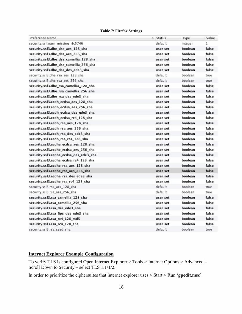
Firefox Example Configuration
For Firefox, you should open Firefox > Preferences > and select Use TLS 1.1/1.2. Next type
“about:config” in the address bar. A warning will come up about changing these settings. Do a
search on security and you will see the algorithms listed as: security.ssl3.rsa_aes_128_sha. In
order to only enable the mandatory ciphersuites the other non-standard ciphersuites must be
disabled in the browser. Double click on each ciphersuite that must be disabled and the Value
will turn to false. See Table 7 below for details.
18
Table 7: Firefox Settings
Internet Explorer Example Configuration
To verify TLS is configured Open Internet Explorer > Tools > Internet Options > Advanced –
Scroll Down to Security – select TLS 1.1/1/2.
In order to prioritize the ciphersuites that internet explorer uses > Start > Run ‘gpedit.msc’

19
The Local Group Policy Editor will open, then click on > Local Computer Policy > Computer
Configuration > Administrative Templates > Network > SSL Configuration Settings – Double
click on the SSL Cipher Suite Order > Click Edit Policy
Steps to Edit the SSL Cipher Suite Order
1. Click on the Enabled radio button.
2. The current cipher suites will be listed under the heading SSL Cipher Suites
3. Copy these into a notepad document and save them as a backup.
4. Open a new blank notepad document
5. Enter the following mandatory ciphersuites:
TLS_RSA_WITH_AES_128_CBC_SHA,TLS_RSA_WITH_AES_256_CBC_SHA
6. Place a comma at the end of every suite name except the last. Make sure there are NO
embedded spaces.
7. Remove all the line breaks so that the cipher suite names are on a single, long line.
8. Copy the above ciphersuites (from step 5) and paste into the box that previously had the listing
of all supported TLS ciphersuites. The maximum length is 1023 characters.
9. It is necessary to restart the computer after modifying this setting for the changes to take
effect.
10. As a reference the following web page was used for these instructions:
http://msdn.microsoft.com/en-
us/library/windows/desktop/bb870930%28v=vs.85%29.aspx#adding__removing__and_prioritizi
ng_cipher_suites
Instructions for Setting the Reference Identifier for Certificate Validation in TLS:
• When the TOE acts as a TLS client to LDAPS servers, it obtains the reference identifiers
from the administrator configured value in the LDAP Identity Source Hostname/IP field.
(Administration application. Menu: Administration > Identity Management > External
Identity Sources. Left-Navigation: LDAP. “Connection” tab. Hostname/IP field)
• When the TOE acts as a TLS client to TLS Secure Syslog servers, it obtains the reference
identifiers from the administrator configured value in the Remote Logging Targets
IP/Host Address field. (Administration application. Menu: Administration > System >
Logging. Left-Navigation: Remote Logging Targets. IP/Host Address field)
• The TOE supports the following presented identifier types:
1. subjectAltName entry of type dNSName (DNS-ID in RFC 6125)
2. CN-ID as defined in RFC 6125 exact case-sensitive match only (i.e., no wildcards
supported in CN-ID)
20
3. subjectAltName entry of type iPAddress; and
4. Wildcards in left-most label subjectAltName entry of type dNSName.
Certificate pinning is unsupported by the TOE.
Certificate Signing Requests :
The detailed instructions to request signed certificate from a CA are listed in the Section –
“Certificate Signing Requests” in Chapter 7 of [2].
Steps for Configuring the Client-side Certificates for TLS Authentication:
The following two steps are required to configure the client-side certificates for TLS
authentication -
1. The TLS server Certificate Authority certificates for the TOE Administration application,
the LDAPS Server and the Secure Syslog Audit Server must be imported into the
“Trusted Certificates” data store. When importing the Trusted Certificate Authority
certificate(s), all of the following must be configured:
a) The checkbox “Validate Certificate Extensions” must be checked.
b) The “Trusted For:” fields must be configured as follows: Check the checkbox “Trust
for client authentication and Syslog” when the TOE acts as a Secure Syslog client to a
Secure Syslog Server and the Trusted Certificate Authority certificate is for the
Secure Syslog Server. When the HTTPS client’s certificate authority certificate is
being used to authenticate to the TOE using client-certificate authentication, the
Certificate Authority Certificate must have the “Trusted for client authentication and
Syslog” checkbox checked.
c) Check the checkbox “Trust for authentication within ISE” when the Certificate
Authority certificate is for the non-TOE LDAPS Server.
2. The configured TOE Server certificate for usage “EAP Authentication” must contain one
of the supported RFC 6125 reference identifiers as configured on the LDAPS Server(s)
and Secure Syslog Audit Server(s).
When the TOE acts as a TLS client to LDAPS servers, it obtains the RFC 6125 reference
identifiers from the administrator configured value in the LDAP Identity Source
Hostname/IP field. (Administration application. Menu: Administration > Identity
Management > External Identity Sources. Left-Navigation: LDAP. “Connection” tab.
Hostname/IP field)
When the TOE acts as a TLS client to TLS Secure Syslog servers, it obtains the reference
identifiers from the administrator configured value in the Remote Logging Targets
IP/Host Address field. (Administration application. Menu: Administration > System >
Logging. Left-Navigation: Remote Logging Targets. IP/Host Address field).

21
The TOE supports the following presented identifier types:
a) subjectAltName entry of type dNSName (DNS-ID in RFC 6125)
b) CN-ID as defined in RFC 6125,
c) subjectAltName entry of type iPAddress; and
d) Wildcards in DNS domain names.
Certificate pinning is unsupported by the TOE.
When ISE acts as a TLS server, it has no prior knowledge of the domain name and IP address of
clients connecting to it. Server Identity verification methods as described in RFC 6125, RFC
2818 and other RFCs are intended more for client’s verification of server identity through
reference identifiers to avoid man-in-the-middle attacks.
ISE will disallow importing ISE certificates with 1024 bit RSA key sizes when ISE is in FIPS
mode. For Diffie-Hellman parameter size of 2048 bits, configuring ISE into FIPS mode
automatically always sets the TLS server ISE Administration application to use Diffie-Hellman
parameter size of 2048 bits.
Steps for Configuring X.509 Certificate Revocation
When ISE (TOE) acts as a TLS client to Secure Syslog Audit Servers, Certificate Revocation
List (CRL) servers must be configured for each of the Intermediate and Trust Anchor Root
Certificate Authorities. The Certificate Revocation List information in the X.509 CRL
Distribution Points extension is not used. Certificate revocation using OCSP responders is
unsupported. when ISE acts as a TLS client to Secure Syslog Audit Servers. The steps for
configuring Certificate Revocation Lists are detailed below in the section “Steps for Configuring
X.509 Certificate Revocation using Certificate Revocation Lists (CRLs)”.
When ISE (TOE) acts as a TLS client to LDAP Over TLS (LDAPS) servers, the Administrator
may configure revocation checks to OCSP responder(s) and/or CRL server(s). When both OCSP
responder and CRL servers are configured, OCSP responder(s) are used to retrieve the certificate
revocation status and if a status determination cannot be made, then the CRL server(s)
configured are used to check revocation status. For OCSP the Administrator may either
configure the OCSP responder information or configure to use the OCSP responder information
contained in the certificate’s Authority Information Access (AIA) Extension. For CRL
Certificate Revocation List (CRL) servers must be configured for each of the Intermediate and
Trust Anchor Root Certificate Authorities. The Certificate Revocation List information in the
X.509 CRL Distribution Points extension is not used. The steps for configuring OCSP are
detailed below in the section “Steps for Configuring X.509 Certificate Revocation using Online
Certificate Status Protocol (OCSP)”. The steps for configuring Certificate Revocation Lists are
detailed below in the section “Steps for Configuring X.509 Certificate Revocation using
Certificate Revocation Lists (CRLs)”.

22
Steps for Configuring X.509 Certificate Revocation using Certificate Revocation Lists
(CRLs)
Configure the CRL information for all Intermediate and Trust Anchor Root Certificate Authority
certificates
Select Menu: Administration > System > Certificates
Left-Side: Select Certificate Management > Trusted Certificates
For each Intermediate Certificate Authority and Trusted Anchor Root Certificate Authority,
import the X.509 certificate and complete the following fields:
Check the checkbox “Download CRL”
Enter the URL to the CRL file in the “CRL Distribution URL” field
Leave the checkboxes unchecked for “Bypass CRL Verification if CRL is not Received” and
“Ignore that CRL is not yet valid or expired”.
Press the “Save” button on each of the Trusted Certificate setting pages.
EXAMPLE:

23
Steps for Configuring X.509 Certificate Revocation using Online Certificate Status
Protocol (OCSP) responders
1. Configure the OCSP Responder
Select Menu: Administration > System > Certificates
Left-Side: Select Certificate Management > OCSP Client Profile
Enter Administrator defined values for the Name and Description fields.
To use the OCSP Responder information contained in the X.509 Authority Information Access
(AIA) extension, check the radio button for “Use OCSP URLs specified in Authority
Information Access (AIA)”.

24
Check the checkbox for “Enable Nonce Extension Support” when your OCSP responder uses
Nonces.
Check the checkbox for “Validate Response Signature”.
Scroll down and press the “Submit” button to save the configuration. Continue to Step 2.
EXAMPLE: Screen shot showing a configuration using the OCSP URLs specified in the
Authority Information Access (AIA) extension.
To enter the OCSP Responder information, overriding any OCSP URLs contained in the X.509
Authority Information Access (AIA) extension, complete the following fields:
Primary Server
URL:

25
Check the checkbox “Enable Nonce Extension Support” if your OCSP
responder is configured to use Nonces.
Check the checkbox “Validate Response Signature”
Optionally an Administrator may configure a secondary OCSP responder that is used if the
Primary OCSP Responder is unreachable.
To configure a secondary OCSP responder,
1. check the “Enable Secondary Server” checkbox
2. Enter the Secondary Server OCSP Responder URL. Check the checkbox “Enable
Nonce Extension Support” when the OCSP responder uses nonces. Check the
checkbox “Validate Response Signature”
Scroll down and click the “Submit” button to save the settings.
EXAMPLE:

26
2. Configure the OCSP responder for all Intermediate and Trust Anchor Root Certificate
Authority certificates
Select Menu: Administration > System > Certificates
Left-Side: Select Certificate Management > Trusted Certificates
For each Intermediate Certificate Authority and Trusted Anchor Root Certificate Authority,
import the X.509 certificate and complete the following fields:
Check the checkbox “Validate against OCSP Server” and pulldown the name of the OCSP Client
Profile created in step 1.
Check the checkboxes “Reject the request if OCSP returns UNKNOWN status” and “Reject the
request if OCSP Responder is unreachable”.
Click the “Save” button to save the settings.
EXAMPLE:

27
3.3.3 Logging Configuration
The TOE includes logging of all Identification & Authentication and relevant administrator
actions at the CLI & GUI by default, but in order to log session idle timeouts (FTA_SSL.3), a
debug level must be set:
1. In the GUI choose Administration > System > Logging.
2. Click Logging > Debug Log Configuration from the navigation panel on the left.
3. Click the radio button 'admin-infra' then click 'Edit'.
4. Change the Log Level pulldown value to 'DEBUG'.
5. Press 'Save' button.
6. Click the radio button ‘infrastructure' then click 'Edit'.
7. Change the Log Level pulldown value to 'DEBUG'.
8. Press 'Save' button.
3.3.4 SSH Public-Key Authentication
To configure SSH public key authentication to the command line interface (CLI), run these
commands in this section on each ISE node –

28
1. Create a CLI user -
• Login to the CLI as an admin-role user.
• Run the Global Configuration username command.
Example showing creation of username foobar with admin-role access.
hostname/userid# configure terminal
hostname/userid(config)# username foobar password plain PggZyTzsJVVXp9N role admin
hostname/userid(config)# end
hostname/userid# copy running-config startup-config
2. Generate SSH RSA keypair for the CLI user created in step 1.
On a non-TOE host generate a SSH RSA keypair using the OpenSSH 'ssh-keygen' program or a
suitable alternative that can format the public key in the format produced by OpenSSH.
EXAMPLE showing a SSH RSA keypair created for user foobar with 4096 bits
# /usr/bin/ssh-keygen -v -b 4096 -t rsa -N K99CNYM8tQP2F8M -C foobar@ise-administration-
node -f /home/foobar/foobar_ise-administration-node.key
Generating public/private rsa key pair.
Your identification has been saved in /home/foobar/foobar_ise-administration-node.key.
Your public key has been saved in /home/foobar/foobar_ise-administration-node.key.pub.
The key fingerprint is:
6f:af:8c:f3:1b:6f:e0:16:22:30:22:ae:da:96:0c:46 foobar@ise-administration-node
The key's randomart image is:
+--[ RSA 4096]----+
| |
| |
| |
|.E. o |
|o. . o S |
|.o . ..o |
|oo . . o+o |
|..+ .+o+. |
|o.. .+=+o |
29
+-----------------+
3. Copy the public key file to a server reachable by the ISE node (TOE)
For example copy the public key file to a SFTP server location.
# cd /home/foobar
# scp foobar_ise-administration-node.key.pub sftpuser@sftp-server:/home/sftpuser/pub/
sftpuser@sftp-server's password:
foobar_ise-administration-node.key.pub 100% 752 0.7KB/s 00:00
4. Using a web browser, login to the ISE Primary Administration Node as a SuperAdmin
role user and configure an ISE 'repository' to enable ISE to retrieve the public key file
from the SFTP server.
Navigate to:
Menu: Administration > System > Maintenance
Left-Side: select 'Repository'
Content: Click 'Add' button.
Repository Name: <Customer Defined Name of Repository>
Protocol: select SFTP or other desired protocol
Location:
Server Name: <hostname or IPv4 address of SFTP server>
Path: <path where the SFTP Username provided in the subsequent
fields has Read access and where the SSH RSA public key was copied in step 3>
Credentials:
User Name: <userid of SFTP server>
Password: <password for userid on SFTP server>
Click 'Submit' button to save values
5. Add SFTP server host key
Logon as an admin-role user to the CLI of the ISE node where the CLI user was created in step
1.
Run the EXEC command 'crypto host_key add host <FQDN or IPv4 address>'
hostname/userid# crypto host_key add host <FQDN or IPv4 address> where <FQDN or IPv4
address> MUST match the value configured under the SFTP Repository 'Server Name' field
value.

30
6. Authorize the use of the public key for the user created in step 1.
• Login to the ISE Command Line Interface (CLI) as the user created in step 1 using the
password authentication method.
• Add the SFTP server host key
Run the EXEC command 'crypto host_key add host <FQDN or IPv4 address>'
hostname/userid# crypto host_key add host <FQDN or IPv4 address> where <FQDN or
IPv4 address> MUST match the value configured under the SFTP Repository 'Server
Name' field value.
• Verify that the SSH RSA public key file is accessible from the ISE SFTP client.
hostname/userid# show repository sftp | include foobar
foobar_ise-administration-node.key.pub
The foobar_ise-administration-node.key.pub filename output after the command indicates
that the public key file in the example is present at the SFTP server and the ISE SFTP
client is able to perform a file listing for the file.
• Authorize the public key for user
Run the 'crypto key import <public key filename> repository <repository name>'
command to authorize use of the SSH RSA public key in the <public key filename> for
the currently logged in CLI user.
EXAMPLE:
hostname/foobar# crypto key import foobar_ise-administration-node.key.pub repository
sftp
• Verify the authorized SSH RSA public key for the user by running the CLI command
'show crypto authorized_keys'
EXAMPLE:
hostname/foobar# show crypto authorized_keys
Authorized keys for foobar
ssh-rsa 6f:af:8c:f3:1b:6f:e0:16:22:30:22:ae:da:96:0c:46 foobar@ise-administration-node
hostname/foobar#
7. Using a non-TOE SSH client with the private key generated from Step 2 authenticate to
the ISE SSH server using public key authentication.
8. Restrict the Key Exchange Methods supported for the SSH protocol via the CLI
• Via the CLI, the admin needs to enter the following configuration commands –
hostname/admin# conf term

31
hostname/admin(config)# service sshd key-exchange-algorithm diffie-hellman-group14-
sha1
3.3.5 Synchronizing Configurations Between TOE Iterations
The TOE includes the ability to run ISE in a distributed installation, where multiple ISE devices
connect to share logs and configuration data. To configure the TOE in this manner follow [2]
under Deploy Cisco ISE Nodes -> Set Up Cisco ISE in a Distributed Environment. In this
configuration, TLS is used by default to secure the connection with the exception of syslog
transfer. To rectify this, the administrator must configure the logging protection as defined in
Section 3.3.6 below.
3.3.6 Logging Protection
If an Security administrator wants to backup the logs between iterations of ISE, or send events to
another IT entity, then protection must be provided for the communications. This requires that
the TLS remote logging target be created and that UDP syslog be removed.
To configure ISE to send secure syslog to a log collector:
1. In the GUI choose Administration > System > Logging.
2. Click Remote Logging Targets from the navigation pane on the left.
a. Click Add.
b. Enter the desired fields for the new Remote Secure Syslog Receiver, including
Name & IP Address or Fully Qualified Hostname
In the IP/Host Address field enter the Fully Qualified Hostname when the Secure
Syslog Server’s X.509 certificate contains a subjectAltName extension of type
dNSName or when the subject Common Name value contains the fully qualified
domain name of the Secure Syslog Server.
In the IP/Host Address field enter the IPv4 address when the Secure Syslog
Server’s X.509 certificate contains a subjectAltName extension of type
iPAddress.
c. Change the pulldown menu for the Target Type to Secure Syslog.
d. Confirm that the port is set to the default standard Secure Syslog port: TCP 6514.
e. Click the checkmark next to Buffer Messages When Server Down.
f. Click the checkmark next to Enable Server Identity Check
g. Change the pulldown menu for the Select CA Certificate to the Certificate
Authority certificate for the Secure Syslog server.
h. Leave other fields at their default value.
i. Ensure that the checkbox for “Include Alarms for this Target” remains unchecked.
If this box gets checked, it will result in UDP insecure Alarms being sent.

32
j. Click Submit.
After the ‘Submit’ is clicked, the newly added syslog node appears in the table of Remote
Logging Targets. By default upon adding the Remote Logging Target the Remote Logging
Target is Enabled. However, syslog messages are unsent to this Remote Logging Target until
the administrator has configured which type of logging audit records desired. The next set of
steps describes how to control what types of audit record syslog messages get sent to the Remote
Logging Target just added:
1. In the GUI choose Administration > System > Logging.
2. Click Logging Categories from the navigation pane on the left.
3. For every radio button do the following:
a. Click radio button
b. Click Edit.
c. Select the Name of the secure Remote Logging Target configured above under the
Targets -> Available box (left side), and press the > button to move it to the
Selected box.
d. Click Save.
Set up Cisco peer ISE nodes to receive secure syslog (another iteration of ISE):
1. In the GUI choose Administration > System > Logging.
2. Click Remote Logging Targets from the navigation panel on the left.
3. Disable the LogCollector.
e. Click the LogCollector radio button.
f. Click Edit.
g. Choose Disabled from the Status drop-down list box.
h. Examine list of log collectors to determine if an additional UDP collector exists
(LogCollector2), and if so, repeat steps a-c for that entry.
i. Click Save.
2. Enable the Secure Syslog Collector.
a. Click the TCPLogCollector radio button.
b. Click Edit.
c. Choose Enabled from the Status drop-down list box.
d. Click Save.
Other TLS-capable syslog targets can also be used as logging targets. Kiwi-syslog is an example
of a syslog server that is supports this functionality. Only the Security Administrator role can
perform modification and deletion of log files.

33
4. Secure Management
4.1 User Roles
The ISE 2.0 TOE by default has multiple supported administrative group roles that compose the
Security administrator role described in the Security Target [5]. The TOE also allows for
customization of other roles. The GUI roles and their configuration are covered in [2] under
Setting Up Cisco ISE Management Access -> Managing Administrators and Admin Access
Policies -> Cisco ISE Administrator Groups. The access table below is provided for reference.
Note that not all commands and menus are relevant to the TSF. Those that are have been
referenced elsewhere in this document.
In addition to this table, all authenticated GUI roles have access to the Home Tab, where access
is given to the following functionality:
• Ability to acknowledge alarms. Thus dismissing these alarms for other
administrative users. NOTE: the configuration changes are still present in the
Configuration Changes Audit report.
• See the splash window that indicates if the version is an ISE Evaluation Copy
• View the post-login banner
• View the status of each of the ISE nodes, CPU, memory and latency
• View alarms, including the ability to view the details for some alarms.
e.g., viewing the details on Configuration Changes in the Configuration Audit Detail are
possible for all authenticated users.
• View number of pass and failed end-user/ device authentications
• View number of profiled endpoints
Refer to [1] for available commands and associated roles and privilege levels at the CLI.
Warning: Usage of the Super Admin role, which has access to all functionality, should be
limited after installation, and users should be granted roles that give the least privilege necessary
to accomplish their work.
Table 8: Default RBAC Menu Access Permissions
Menu Access Name RBAC Group Permissible Set of Menu
Items
Super Admin Menu Access Super Admin • Operations > All menu items
• Policy > All menu items
• Administration > All menu
items
Policy Admin Menu Access Policy Admin • Operations > All menu items
• Policy > All menu items
• Administration >
– Identity Management > All
menu items
– System > Settings

34
Helpdesk Admin Menu
Access
Helpdesk Admin • Operations > All menu items
Identity Admin Menu Access Identity Admin • Operations > All menu items
• Administration >
– Identity Management > All
menu items
Network Admin Menu
Access
Network Device Admin • Operations > All menu items
• Administration >
– Network Resources > All
menu items
System Admin Menu Access System Admin • Operations >
Authentication, Alarms,
Reports, and Troubleshoot
• Administration >
– System > All menu items
RBAC Admin Menu Access RBAC Admin • Operations > All menu items
• Administration >
– Admin Access > All menu
items
MnT Admin Menu Access MnT (Monitoring) Admin • Operations > All menu items
4.2 Passwords
To prevent administrators from choosing insecure passwords, each password must meet the
following requirements:
• At least 15 characters long
• Composed of any combination of characters that includes characters for at least 3 of
these four character sets: upper case letters, lower case letters, numbers, and the
following special characters: “!”, “@”, “#”, “$”, “%”, “^”, “&”, “*”, “(“, “)”
At: Administration > System > Admin Access > Authentication, the password length can be set
as well as additional password policies, such as enforcing the use of multiple character sets.
Configuration of password policies is limited to the Super Admin and System Admin group roles
on the GUI.
4.3 User Lockout
To Configure authentication lockout:
• Administration > System > Admin Access > Authentication > Lock/Suspend Settings
• Make sure ‘Suspend or Lock Account with Incorrect Login Attempts’ is checked
• Specify the number of attempts (ranging from 3 to 20)
• Select ‘Lock Account’
• Optional: Configure the Lockout message sent to the user once the account is locked.

35
4.4 Clock Management
For instructions to manually set the local hardware clock, refer to the clock command in [1].
To configure the system clock through the GUI, navigate to Administration > System > Settings
> System Time.
Configuration of clock settings is limited to the CLI administrator and Super Admin and System
Admin group roles on the GUI.
4.5 Identification and Authentication
Configuration of Identification and Authentication settings is restricted to the CLI administrator
and Identity Admin, Super Admin, and System Admin group roles on the GUI.
The ISE 2.0 can be configured to use the following authentication methods:
• Remote authentication (Active Directory and LDAP)
o Refer to “Authentication Stores” elsewhere in this document for more details.
o Requires user to provide correct username and password combination to
authenticate
• Local authentication
o administrative password - Requires user to provide correct username and
password combination to authenticate
o public-key based - Requires user to provide correct username and private key
combination to authenticate
To limit identification and authentication attempts by the TOE, the following items can be
configured to limit based on date/time, concurrent sessions, and IPv4/MAC address.
• Date/Time Range - Administration > System > Admin Access > Authentication >
Account Disable Policy
• Concurrent Sessions – Administration > System > Admin Access > Settings > Access >
Session
• IPv4/MAC Address - Administration > System > Admin Access > Settings > Access > IP
Access
4.6 Login Banners
The TOE may be configured at the GUI by the System admin and Super admin with pre-login
banners for both the CLI and the GUI. These banners will be displayed before the username and
password prompts, and by default, they will say “Authorized users only!”. To customize the
banner with the required text for your organization, go to the Administration > System > Admin
Access > Settings > Access page and do the following:
1. On the left-side menu, double-click on "Settings" then double-click on "Access".
2. Under the GUI Sessions section, check the radio button to the left of "Pre-login banner".

36
3. Fill in the field with the required banner text for your organization, up to a 1520 character
maximum.
4. Under the CLI Sessions section, check the radio button to the left of "Pre-login banner".
5. Fill in the field with the required banner text for your organization, up to a 1520 character
maximum.
6. Press the 'Save' button to commit the changes made in steps 1.3 and 1.4.
The CLI banner may also be configured by the CLI admin using the following commands:
# banner install pre-login <filename> repository <reponame>
where filename is the file that contains the banner, and reponame is the location of the
file. The command ‘banner remove pre-login’ can be used to remove the banner.
The GUI banner will look like the following when configured:
The SSH banner will look like the following when the CLI banner is configured:
ssh admin@generic-domain
Authorized users only!
admin@generic-domain 's password:
Last login: Thu Feb 23 20:23:11 2012 from host-lnx2.generic-domain.com
generic-domain/admin#

37
4.7 Virtual Private Networks (VPN)
4.7.1 IPsec Overview
The TOE includes an instance of the Embedded Services Router 5921 [ESR], running IOS
15.5(3)M5. The ESR is a software-only solution for routing capabilities. The ESR provides IPsec
session capabilities for ISE v2.2 to secure the channel between the TOE and NAS. The TOE
allows all privileged administrators to configure Internet Key Exchange (IKE) and IPSEC
policies. IPsec provides the following network security services:
• Data confidentiality--The IPsec sender can encrypt packets before transmitting them
across a network.
• Data integrity--The IPsec receiver can authenticate packets sent by the IPsec sender to
ensure that the data has not been altered during transmission.
• Data origin authentication--The IPsec receiver can authenticate the source of the sent
IPsec packets. This service is dependent upon the data integrity service.
• Anti-replay--The IPsec receiver can detect and reject replayed packets.
IPsec provides secure tunnels between two peers, such as two routers. The privileged
administrator defines which packets are considered sensitive and should be sent through these
secure tunnels and specifies the parameters that should be used to protect these sensitive packets
by specifying the characteristics of these tunnels. When the IPsec peer recognizes a sensitive
packet, the peer sets up the appropriate secure tunnel and sends the packet through the tunnel to
the remote peer.
More accurately, these tunnels are sets of security associations (SAs) that are established
between two IPsec peers. The SAs define the protocols and algorithms to be applied to sensitive
packets and specify the keying material to be used by the two peers. SAs are unidirectional and
are established per security protocol (AH or ESP).
With IPsec, privileged administrators can define the traffic that needs to be protected between
two IPsec peers by configuring access lists and applying these access lists to interfaces using
crypto map sets. Therefore, traffic may be selected on the basis of the source and destination
address, and optionally the Layer 4 protocol and port. (The access lists used for IPsec are only
used to determine the traffic that needs to be protected by IPsec, not the traffic that should be
blocked or permitted through the interface. Separate access lists define blocking and permitting
at the interface.)
A crypto map set can contain multiple entries, each with a different access list. The crypto map
entries are searched in a sequence--the router attempts to match the packet to the access list
specified in that entry.
When a packet matches a permit entry in a particular access list, and the corresponding crypto
map entry is tagged as cisco, connections are established, if necessary. If the crypto map entry is
tagged as ipsec-isakmp, IPsec is triggered. If there is no SA that the IPsec can use to protect this
traffic to the peer, IPsec uses IKE to negotiate with the remote peer to set up the necessary IPsec
SAs on behalf of the data flow. The negotiation uses information specified in the crypto map
entry as well as the data flow information from the specific access list entry.

38
Once established, the set of SAs (outbound to the peer) is then applied to the triggering packet
and to subsequent applicable packets as those packets exit the router. "Applicable" packets are
packets that match the same access list criteria that the original packet matched. For example, all
applicable packets could be encrypted before being forwarded to the remote peer. The
corresponding inbound SAs are used when processing the incoming traffic from that peer.
Access lists associated with IPsec crypto map entries also represent the traffic that the router
needs protected by IPsec. Inbound traffic is processed against crypto map entries--if an
unprotected packet matches a permit entry in a particular access list associated with an IPsec
crypto map entry, that packet is dropped because it was not sent as an IPsec-protected packet.
Crypto map entries also include transform sets. A transform set is an acceptable combination of
security protocols, algorithms, and other settings that can be applied to IPsec-protected traffic.
During the IPsec SA negotiation, the peers agree to use a particular transform set when
protecting a particular data flow.
4.7.1.1 IKEv1 Transform Sets
An Internet Key Exchange version 1 (IKEv1) transform set represents a certain combination of
security protocols and algorithms. During the IPsec SA negotiation, the peers agree to use a
particular transform set for protecting a particular data flow.
Privileged administrators can specify multiple transform sets and then specify one or more of
these transform sets in a crypto map entry. The transform set defined in the crypto map entry is
used in the IPsec SA negotiation to protect the data flows specified by that crypto map entry's
access list.
During IPsec security association negotiations with IKE, peers search for a transform set that is
the same at both peers. When such a transform set is found, it is selected and applied to the
protected traffic as part of both peers' IPsec SAs. (With manually established SAs, there is no
negotiation with the peer, so both sides must specify the same transform set.)
Note: If a transform set definition is changed during operation that the change is not applied to
existing security associations, but is used in subsequent negotiations to establish new SAs. If you
want the new settings to take effect sooner, you can clear all or part of the SA database by using
the clear crypto sa command.
The following settings must be set in configuring the IPsec with IKEv1 functionality for the
TOE:
TOE-common-criteria # conf t
TOE-common-criteria (config)#crypto isakmp policy 1
TOE-common-criteria (config-isakmp)# hash sha
TOE-common-criteria (config-isakmp)# encryption aes
This configures IPsec IKEv1 to use AES-CBC-128 for payload encryption. AES-
CBC-256 can be selected with ‘encryption aes 256’.
Note: the authorized administrator must ensure that the keysize for this setting is
greater than or equal to the keysize selected for ESP in Section 4.6.2 below. If

39
AES 128 is selected here, then the highest keysize that can be selected on the TOE
for ESP is AES 128 (either CBC).
Note: Both confidentiality and integrity are configured with the hash sha and
encryption aes commands respectively. As a result, confidentiality-only mode is
disabled.
TOE-common-criteria (config-isakmp)# authentication pre-share
This configures IPsec to use pre-shared keys. X.509 v3 certificates are also
supported for authentication of IPsec peers. See Section 4.6.3 below for additional
information.
TOE-common-criteria(config-isakmp)# exit
TOE-common-criteria(config)# Crypto isakmp key cisco123!cisco123!CISC address
11.1.1.4
Note: Pre-shared keys on the TOE must be at least 22 characters in length and
can be composed of any combination of upper and lower case letters, numbers,
and special characters (that include: “!”, “@”, “#”, “$”, “%”, “^”, “&”, “*”,
“(“, and “)”).
The TOE supports pre-shared keys up to 128 bytes in length. While longer keys
increase the difficulty of brute-force attacks, longer keys increase processing
time.
TOE-common-criteria (config-isakmp)# group 14
This selects DH Group 14 (2048-bit MODP) for IKE, but 19 (256-bit Random
ECP), 24 (2048-bit MODP with 256-bit POS), and 20 (384-bit Random ECP) are
also allowed and supported.
TOE-common-criteria (config-isakmp)# lifetime 86400
The default time value for Phase 1 SAs is 24 hours (86400 seconds), but this
setting can be changed using the command above with different values.
TOE-common-criteria (config-isakmp)# crypto isakmp aggressive-mode disable
Main mode is the default mode and the crypto isakmp aggressive-mode disable
ensures all IKEv1 Phase 1 exchanges will be handled in the default main mode.
TOE-common-criteria(config-isakmp)#exit
4.7.1.2 IKEv2 Transform Sets
An Internet Key Exchange version 2 (IKEv2) proposal is a set of transforms used in the
negotiation of IKEv2 SA as part of the IKE_SA_INIT exchange. An IKEv2 proposal is regarded
as complete only when it has at least an encryption algorithm, an integrity algorithm, and a
Diffie-Hellman (DH) group configured. If no proposal is configured and attached to an IKEv2
policy, then the default proposal is used in the negotiation, and it contains selections that are not
valid for the TOE. Thus the following settings must be set in configuring the IPsec with IKEv2
functionality for the TOE:

40
TOE-common-criteria # conf t
TOE-common-criteria (config)#crypto ikev2 proposal sample
TOE-common-criteria (config-ikev2-proposal)# integrity sha1
TOE-common-criteria (config-ikev2-proposal)# encryption aes-cbc-128
This configures IPsec IKEv2 to use AES-CBC-128 for payload encryption. AES-
CBC-256 can be selected with ‘encryption aes-cbc-256’.
Note: the authorized administrator must ensure that the keysize for this setting is
greater than or equal to the keysize selected for ESP in Section 4.6.2 below. If
AES 128 is selected here, then the highest keysize that can be selected on the TOE
for ESP is AES 128 (CBC).
Note: Both confidentiality and integrity are configured with the hash sha and
encryption aes commands respectively. As a result, confidentiality-only mode is
disabled.
TOE-common-criteria (config-ikev2-proposal)# group 14
This selects DH Group 14 (2048-bit MODP) for IKE, but 19 (256-bit Random
ECP), 24 (2048-bit MODP with 256-bit POS), and 20 (384-bit Random ECP) are
also allowed and supported.
TOE-common-criteria (config)#crypto ikev2 keyring keyring-1
TOE-common-criteria (config-ikev2-keyring)# peer peer1
TOE-common-criteria (config-ikev2-keyring-peer)# address 0.0.0.0 0.0.0.0
TOE-common-criteria (config-ikev2-keyring-peer)# pre-shared-key
cisco123!cisco123!CISC
This section creates a keyring to hold the pre-shared keys referenced in the steps
above. In IKEv2 these pre-shared keys are specific to the peer.
Note: Pre-shared keys on the TOE must be at least 22 characters in length and
can be composed of any combination of upper and lower case letters, numbers,
and special characters (that include: “!”, “@”, “#”, “$”, “%”, “^”, “&”, “*”,
“(“, and “)”).
The TOE supports pre-shared keys up to 128 bytes in length. While longer keys
increase the difficulty of brute-force attacks, longer keys increase processing
time.
HEX keys generated off system can also be input for IKEv2 using the following
instead of the pre-shared-key command above: ‘pre-shared-key hex [hex key]’.
For example: pre-shared-key hex 0x6A6B6C.
This configures IPsec to use pre-shared keys. X.509 v3 certificates are also
supported for authentication of IPsec peers. See Section 4.6.3 below for
additional information.

41
TOE-common-criteria (config)#crypto logging ikev2
This setting enables IKEv2 syslog messages.
Note: The configuration above is not a complete IKE v2 configuration, and that additional
settings will be needed. See [18] Configuring Internet Key Exchange Version 2 (IKEv2) for
additional information on IKE v2 configuration.
4.7.2 IPsec Transforms and Lifetimes
Regardless of the IKE version selected, the TOE must be configured with the proper transform
for IPsec ESP encryption and integrity as well as IPsec lifetimes.
TOE-common-criteria(config)# crypto ipsec transform-set example esp-aes 128 esp-
sha-hmac
Note that this configures IPsec ESP to use HMAC-SHA-1 and AES-CBC-128. To
change this to the other allowed algorithms the following options can replace
‘esp-aes 128’ in the command above:
Encryption Algorithm Command
AES-CBC-256 esp-aes 256
Note: The size of the key selected here must be less than or equal to the key size
selected for the IKE encryption setting in 4.6.1.1 and 4.6.1.2 above. If AES-
CBC-128 was selected there for use with IKE encryption, then only AES-CBC-
128 may be selected here.
TOE-common-criteria(config-crypto)#mode tunnel
This configures tunnel mode for IPsec. Tunnel is the default, but by explicitly
specifying tunnel mode, the router will request tunnel mode and will accept only
tunnel mode.
TOE-common-criteria(config-crypto)#mode transport
This configures transport mode for IPsec.
TOE-common-criteria (config)#crypto ipsec security-association lifetime seconds
28800
The default time value for Phase 2 SAs is 1 hour. There is no configuration
required for this setting since the default is acceptable, however to change the
setting to 8 hours as claimed in the Security Target the crypto ipsec security-
association lifetime command can be used as specified above.
TOE-common-criteria (config)#crypto ipsec security-association lifetime kilobytes
100000

42
This configures a lifetime of 100 MB of traffic for Phase 2 SAs. The default
amount for this setting is 2560KB, which is the minimum configurable value for
this command. The maximum configurable value for this command is 4GB.
Additional information regarding configuration of IPsec can be found in [10]. The IPSEC
commands are dispersed within the Security Command References.
• This functionality is available to the Privileged Administrator. Configuration of VPN
settings is restricted to the privileged administrator.
4.7.3 NAT Traversal
For successful NAT traversal over an IOS-XE NAT device for an IPsec connection between two
IOS-XE peers, the following configuration needs to be used (Also refer to Chapter 7 of [21])–
On an IOS NAT device (router between the IPsec endpoints):
config terminal
ip nat service list <ACL-number> ESP spi-match
access-list <ACL-number> permit <protocol> <local-range> <remote-range>
end
On each IOS peer (IPsec router endpoints):
config terminal
crypto ipsec nat-transparency spi-matching
end
4.8 X.509 Certificates The TOE may be configured by the privileged administrators to use X.509v3 certificates to authenticate IPsec peers. RSA certificates are supported. Creation of these certificates and loading them on the TOE is covered in the section – “How to Configure Certificate Enrollment for a PKI” in [22], and a portion of the TOE configuration for use of these certificates follows below.
4.8.1 Creation of the Certificate Signing Request
The certificate signing request for the TOE will be created using the RSA key pair and the
domain name configured in Section 3.3.1 above.
In order for a certificate signing request to be generated, the TOE must be configured with a,
hostname and trustpoint.
1. Enter configure terminal mode:
Device # configure terminal

43
2. Specify the hostname: hostname name
Device(config)# hostname asrTOE
3. Configure the trustpoint: crypto pki trustpoint trustpoint-name
Device (config)#crypto pki trustpoint ciscotest
4. Configure an enrollment method: enrollment [terminal, url url]
Device (ca-trustpoint)#enrollment url http://192.168.2.137:80
5. Configure subject-name settings for the certificate: subject-name
CN=hostname.domain.com,OU=OU-name
Device (ca-trustpoint)#subject-name CN=asrTOE.cisco.com,OU=TAC
6. Set revocation check method: revocation-check crl
Device (ca-trustpoint)#revocation-check crl
Device (ca-trustpoint)#exit
7. Create the certificate signing request: crypto pki enroll trustpoint-name
Device (config)#crypto pki enroll ciscotest
4.8.2 Securely Connecting to a Certificate Authority for Certificate Signing
The TOE must communicate with the CA for Certificate Signing over IPSEC. This
authentication will use pre-shared keys.
Following are sample instructions to configure the TOE to support an IPsec tunnel with aes
encryption, with 10.10.10.102 as the IPsec peer IP on the CA, 10.10.10.110 as the local TOE IP.
TOE-common-criteria#configure terminal
TOE-common-criteria(config)#crypto isakmp policy 1
TOE-common-criteria(config-isakmp)#encryption aes
TOE-common-criteria(config-isakmp)#authentication pre-share
TOE-common-criteria(config-isakmp)#group 14
TOE-common-criteria(config-isakmp)#lifetime 86400
TOE-common-criteria(config)#crypto isakmp key [insert 22 character preshared key]
address 10.10.10.101
TOE-common-criteria(config)#crypto ipsec transform-set sampleset esp-aes esp-sha-
hmac
TOE-common-criteria(cfg-crypto-trans)#mode tunnel
TOE-common-criteria(config)#crypto map sample 19 ipsec-isakmp
TOE-common-criteria(config-crypto-map)#set peer 10.10.10.102
TOE-common-criteria(config-crypto-map)#set transform-set sampleset
TOE-common-criteria(config-crypto-map)#set pfs group14
TOE-common-criteria(config-crypto-map)#match address 170
TOE-common-criteria(config-crypto-map)#exit

44
TOE-common-criteria(config)#interface g0/0
TOE-common-criteria(config-if)#ip address 10.10.10.110 255.255.255.0
TOE-common-criteria(config-if)#crypto map sample
TOE-common-criteria(config-if)#exit
TOE-common-criteria(config)# access-list 170 permit ip 10.10.10.0 0.255.255.255
10.10.10.0 0.255.255.255
4.8.3 Authenticating the Certificate Authority
The TOE must authenticate the CA by acknowledging its attributes match the publicly posted
fingerprint. The TOE administrator must verify that the output of the command below matches
the fingerprint of the CA on its public site.
1. Authenticate the CA: crypto ca authenticate trustpoint-name
Device (config)#crypto ca authenticate ciscotest
Certificate has the following attributes:
Fingerprint MD5: 8DE88FE5 78FF27DF 97BA7CCA 57DC1217
Fingerprint SHA1: 271E80EC 30304CC1 624EEE32 99F43AF8 DB9D0280
2. % Do you accept this certificate? [yes/no]: yes
Trustpoint CA certificate accepted.
4.8.4 Storing Certificates to a Local Storage Location
Certificates are stored to NVRAM by default; however, some routers do not have the required
amount of NVRAM to successfully store certificates. All Cisco platforms support NVRAM and
flash local storage. Depending on the platform, an authorized administrator may have other
supported local storage options including bootflash, slot, disk, USB flash, or USB token. During
run time, an authorized administrator can specify what active local storage device will be used to
store certificates. For more detailed information see the Public Key Infrastructure Configuration
Guide Guidance document section "How to Configure PKI
Storage." - http://www.cisco.com/c/en/us/td/docs/ios-xml/ios/sec_conn_pki/configuration/xe-
3s/sec-pki-xe-3s-book.pdf
4.8.5 How to Specify a Local Storage Location for Certificates
The summary steps for storing certificates locally to the TOE are as follows:
1. Enter configure terminal mode:
Device # configure terminal
45
2. Specify the local storage location for certificates: crypto pki certificate storage location-
name
Device(config)# crypto pki certificate storage flash:/certs
3. Exit:
Device(config)# exit
4. Save the changes made:
Device# copy system:running-config nvram:startup-config
5. Display the current setting for the PKI certificate storage location:
Device# show crypto pki certificates storage
The following is sample output from the show crypto pki certificates storage command, which
shows that the certificates are stored in the certs subdirectory of disk0:
Device# show crypto pki certificates storage
Certificates will be stored in disk0:/certs/
4.8.6 Configuring a Revocation Mechanism for PKI Certificate Status Checking
Perform this task to set up the certificate revocation mechanism--CRLs or OCSP--that is used
to check the status of certificates in a PKI.
Use the revocation-check command to specify at least one method (OCSP, CRL, or skip the
revocation check) that is to be used to ensure that the certificate of a peer has not been
revoked. For multiple methods, the order in which the methods are applied is determined by the
order specified via this command.
If the TOE does not have the applicable CRL and is unable to obtain one, or if the OCSP server
returns an error, the TOE will reject the peer’s certificate--unless an administrator includes the
‘none’ keyword in your configuration. If the 'none' keyword is configured, a revocation check
will not be performed and the certificate will always be accepted.
When using OCSP, nonces, unique identifiers for OCSP requests, are sent by default during
peer communications with a OCSP server. The use of nonces offers a more secure and reliable
communication channel between the peer and OCSP server. If the OCSP server does not support
nonces, an authorized administrator may disable the sending of nonces.
Note: The TOE supports use of OCSP only when using RSA certs.
4.8.7 Manually Overriding the OCSP Server Setting in a Certificate
Administrators can override the OCSP server setting specified in the Authority Information
Access (AIA) field of the client certificate or set by the issuing the ocsp url command. One or
more OCSP servers may be manually specified, either per client certificate or per group of client
certificates by the match certificate override ocsp command. The match certificate override
ocspcommand overrides the client certificate AIA field or the ocsp urlcommand setting if a client
certificate is successfully matched to a certificate map during the revocation check

46
4.8.8 Configuring Certificate Chain Validation
Perform this task to configure the processing level for the certificate chain path of peer
certificates.
Prerequisites:
The device must be enrolled in your PKI hierarchy.
The appropriate key pair must be associated with the certificate.
1. Enter configure terminal mode:
TOE-common-criteria# configure terminal
2. Set the crypto pki trustpoint name:
TOE-common-criteria(config)# crypto pki trustpoint ca-sub1
3. Configure the level to which a certificate chain is processed on all certificates including
subordinate CA certificates using the chain-validation [{stop | continue} [parent-
trustpoint]] command:
TOE-common-criteria(ca-trustpoint)# chain-validation continue ca-sub1
4. Use the stop keyword to specify that the certificate is already trusted. This is the default
setting.
5. Use the continue keyword to specify that the that the subordinate CA certificate
associated with the trustpoint must be validated.
6. The parent-trustpoint argument specifies the name of the parent trustpoint the certificate
must be validated against.
7. Exit:
TOE-common-criteria(ca-trustpoint)# exit
Note: A trustpoint associated with the root CA cannot be configured to be validated to the next
level. The chain-validation command is configured with the continue keyword for the trust point
associated with the root CA, an error message will be displayed and the chain validation will
revert to the default chain-validation command setting.
4.8.9 Certificate Validation
By default the TOE will validate the certificate of the IPsec peer including a Basic Constraints
extension. No configuration is required by the administrator. Optionally as a way to test a Basic
Constraints extension, the administrator can add subject name restrictions to the CA root
trustpoint. Refer to How to Configure Certificate Enrollment for a PKI” in [22]. A portion of an
example TOE configuration follows below.
TOE-common-criteria (config)# crypto pki certificate map <certificate map name> 1
subject-name co example
TOE-common-criteria (config)# crypto pki trustpoint CAroot
TOE-common-criteria (ca-trustpoint)# enrollment terminal
TOE-common-criteria (ca-trustpoint)# match certificate <certificate map name>
47
TOE-common-criteria (ca-trustpoint)#end
TOE-common-criteria (config)# crypto pki trustpoint CA sub
TOE-common-criteria (ca-trustpoint)# enrollment terminal
TOE-common-criteria (ca-trustpoint)# subject-name
CN=example.organization.com,OU=Spiral Dept,O=Example
TOE-common-criteria (ca-trustpoint)# match certificate <certificate map name>
TOE-common-criteria (ca-trustpoint)#end
The administrator should find an error message stating that certificate chain validation has failed
because a certificate in the chain was not a valid CA certificate.
4.8.10 Setting X.509 for use with IKE
Once X.509v3 keys are installed on the TOE, they can be set for use with IKEv1 with the
commands:
TOE-common-criteria (config)#crypto isakmp policy 1
TOE-common-criteria (config-isakmp)# authentication rsa-sig
And for IKEv2 with the commands:
TOE-common-criteria (config)#crypto ikev2 profile sample
TOE-common-criteria(config-ikev2-profile)#authentication [remote | local] rsa-sig
If an invalid certificate is loaded, authentication will not succeed.
4.8.11 Deleting Certificates
If the need arises, certificates that are saved on the router can be deleted. The router saves its
own certificates and the certificate of the CA.
To delete the router's certificate from the router's configuration, the following commands can be
used in global configuration mode:
Router# show crypto ca certificates [Displays the certificates stored on router]
Router(config)# crypto ca certificate chain name [Enters certificate chain configuration
mode]
Router(config-cert-cha)# no certificate certificate-serial-number [deletes the certificate]
To delete the CA's certificate, the entire CA identity must be removed, which also removes all
certificates associated with the CA—router's certificate and the CA certificate. To remove a CA
identity, the following command in global configuration mode can be used:

48
Router(config)# no crypto ca identity name [Deletes all identity information and certificates
associated with the CA]
4.9 User Session Establishment – Denial Attributes
4.9.1 Administrator-defined Time and Date Ranges
The following steps need to be taken to deny user session establishment based on Administrator-
defined Time and Date Ranges –
Login to the Administration application user interface as a 'Policy Admin' role and configure the
following steps:
1. Create Time and Date Condition
Define one or more date and time ranges when access must be denied
Menu: Policy > Policy Elements > Conditions
Left-Side Navigation: Common > Time and Date
Click 'Add' to add a new Time and Date condition.
Enter 'Condition Name' value.
Optionally enter 'Description' value.
Under 'Standard Settings' section specify the specific dates or time to deny access by
clicking the radio button(s) for -
'Specific Date Range', 'Specific Date' and/or 'Specific Hours' and/or 'Specific Days'.
Under the 'Exceptions' section list any exceptions when access must be allowed.
2. Create Authorization Policy Rule for the Time and Date Condition(s)
Administrator sets an authorization policy rule denying access for the configured time
and date range - Menu: Policy > Authorization
a. In applicable row, Pulldown "Edit" and select either "Insert New Row Above" or "Insert
New Row Below".
b. Optionally select which identity groups the rule applies to or leave the default of 'All'
identities for the rule to apply to all users
c. Under the condition(s) click the "+"
Choose the "Select Existing Condition from Library" option.
Condition Name: click the 'Select Condition' pulldown and
49
select the 'Time and Date Conditions' >
name of the time and date condition(s) created in
step 1.
Multiple time and date conditions may be added with 'AND' or 'OR'.
Other conditions other than 'time and date conditions' may also be added in the rule. For
example it is possible to restrict access based on time and date conditions to only certain
types of users.
4.9.2 Administrator defined Maximum Concurrent User Sessions
User session establishment can be denied based on Administrator-defined maximum number of
concurrent user sessions, maximum number of concurrent sessions per user group and/or
maximum number of concurrent sessions per user within a certain user group. This can be
achieved by logging into to the Administration application user interface in a 'Policy Admin' role
and configuring the steps described in:
http://www.cisco.com/c/en/us/support/docs/security/identity-services-engine-22/204463-
Configure-Maximum-Concurrent-User-Sessio.html
4.9.3 Administrator defined list of Endpoint IPv4 addresses and/or subnets, IPv6 addresses and/or subnets, and/or MAC Addresses
The following steps need to be taken to deny user session establishment based on endpoint
IPV4/IPV6 addresses, MAC addresses and subnets –
Login to the Administration application user interface as a 'Policy Admin' role and configure the
following steps:
1. Create a new End Station Network Condition with IP Address(es) and/or MAC
address(es) to deny access to.
➢ Define an End Station Network Condition with a list of endpoint address(es) that
must be Denied access.
Menu: Policy > Policy Elements > Conditions
Left-Side Navigation: Network Conditions > Endstation Network Conditions

50
Click 'Add'
➢ Under the 'IP Addresses' tab list IPv4 address(es) or subnet(s), and/or IPv6
address(es) or subnet(s) to deny access.
➢ Under the 'MAC Addresses' tab list the MAC address(es) to deny access.
2. Create an Authentication Policy Rule or Authorization Policy Rule to deny access based
on End Station Network Address(es)
➢ Administrator sets an authentication policy rule or an authorization policy rule
denying access for the specified IP address(es) and/or MAC address(es) defined in
step 1.
Menu: Policy > Authentication; or
Menu: Policy > Authorization
Insert New Row within "Dot1X" and/or "MAB"
▪ Enter Condition and 'Create New Condition'.
Select Attribute: Select 'Network Condition' > [Name of EndStation
Network Condition created in Step 1.] Equals set value to 'True'
▪ Select 'Internal Users' and modify the Identity source from 'Internal Users'
to 'Deny Access'.
Click 'Done' and Click 'Save' button to persist the settings.
4.10 Configuring Radius
To configure Radius:
• Choose Administration > System > Settings.
• From the Settings navigation pane, click Protocols.
• Choose RADIUS.
• Enter the details as required to define the RADIUS settings.
• Click Save to save the settings.
To connect the TOE to an external RADIUS server:
• Choose Administration > External RADIUS Servers
• Select New
• Specify the Name
• Specify the Host IP
• Specify the Shared Secret

51
• Specify the Authentication Port
• Specify the Accounting Port
• Specify the Server Timeout
• Specify the Connection Attempts
• Click Submit to save the settings.
All Access-Requests sent to the TOE are logged.
4.11 Configuring EAP-TLS
To configure EAP-TLS:
• Choose Administration > System > Settings > Protocols > EAP-TLS.
• Enter the details as required to define the EAP-TLS protocol.
• Click Save to save the EAP-TLS settings.
4.12 Verifying Software Version
The TOE allows for the CLI administrator to verify the version of software running by entering
the command
show application version ise
The console displays information similar to the following screen. The version must be 2.0.1 to be
in the evaluated configuration.
To check the Cisco Application Deployment Engine (ADE) Release 3.0 operating system (ADE-
OS) version, at the system prompt, enter the command
show version
The console displays an output similar to the following:
Cisco Application Deployment Engine OS Release: 3.0
ADE-OS Build Version: 3.0.2.216
4.13 Services on the Box
Appendix B -> Cisco ISE 3400/3500 Series Appliance Ports Reference for the list of Services
running on ISE and their available ports and interfaces.
4.14 Secure Connection Recovery
In the event of failure of the secure connections used by the TOE the following should be done:
1. TOE to TOE for audit data and configuration data: the secure connection will re-
establish once a connection is available again between iterations of the TOE. The
administrator should confirm connection settings are still correct for each TOE iteration
per Section 3.3.5, above.
52
2. TOE to LDAP (and ActiveDirectory): the secure connection will re-establish once a
connection is available again between the TOE and the remote authentication server. The
administrator should confirm connection settings are still correct per [2] as referenced in
Section 3.2.4, above.
3. TOE to Syslog server: When the optional ISE Remote Logging Target configuration
field Buffer Messages When Server Down field is checked on a Remote Logging
target, during failure to reach Secure Syslog servers, the audit data is not lost as the audit
records are stored and forwarded as soon as communications is re-established in a store-
and-forward manner. When the Buffer Messages when Server Down field is unchecked,
audit records may be lost during the period in which secure communications was lost to
any Secure Syslog server.
5. Security Relevant Events ISE 2.0 can maintain logs in multiple locations: local storage of the generated audit records, and
when configured for a syslog backup will simultaneously offload those events to a peer
instantiation of ISE or a different log server. ISE 2.0 administrators should review logs at both
locations. Instructions for viewing logs are found in Section 5.1 below.
Audit events are simultaneously sent to the external server and the local store upon creation. If
the external server is not available the TOE will buffer events until they can be sent.
The audit fields in each audit event will contain at a minimum the following:
Example event: 2013-03-16 01:32:21.512 +00:00 0000000997 60079 NOTICE
Administrator-Login: A failure to establish an SSL session was detected,
ConfigVersionId=4, AdminIPAddress=10.34.84.155, OperationMessageText=no cipher
suites in common, PortNumber=443]
Date: In year-month-day format: 2013-03-16
Time: In hour:minute:second:millisecond format:01:32:21.512
Type of event: Administrator-Login
Subject identity: Available when the action is run by an authorized TOE administrator user such
as “user: lab”. In cases where the audit event is not associated with an authorized user, an IP
address may be provided for the Non-TOE endpoint and/ or TOE.
IP address: (Optional) May be provided along with the subject identity of a specific authorized
TOE administrator: AdminIPAddress=10.34.84.155.
Port number: (Optional) May be provided along with the IP address for connections to the box:
PortNumber=443.
Outcome (Success or Failure): Success may be explicitly stated with “success” or “passed”
contained within the audit event or is implicit in that there is not a failure or error message.
More specifically for failed logins, “authentication failed” will appear in the audit event. For
successful logins, “authentication succeeded” will appear in the associated audit event. For

53
failed events “failure” will be denoted in the audit event. For other audit events a detailed
description of the outcome may be given in lieu of an explicit success or failure. For example,
for termination of an SSH session a detailed description is given in the associated audit event:
“Received disconnect from 10.34.85.13: 11: Closed due to user request.”
Additional Audit Information: As described in Column 3 of Table 9 below.
As noted above, the information includes at least all of the required information. Example audit
events are included below by Security Functional Requirement.
Audit events can also be viewed at the GUI, where they are displayed with field labels that
closely correspond to the required logging fields in the NDcPP. Following is an example log
from the Configuration Audit Log that tracks changes made to the TOE by an administrator.
In this example, the date and time are in the ‘Logged At’ field; the type of event is in the ‘Object
Type’ field; the subject identity is in the ‘Administrator’ field; and the outcome is in the ‘Event’
field where it is noted that the configuration was changed. No event would be generated in this
log for failed configuration attempts due to the nature of the GUI. Privileges that are not granted
to an administrator role do not even appear on their screen as an option, thus they have no access
to them.
Table 9: Auditable Events
Requirement Auditable
Events
Additional Audit
Record Contents
Sample Record and Location
FCS_NRO.1 Client request for
which the TOE
does not have a
shared secret
Identity of the client,
contents of EAP-
response (if present).
Feb 22 20:30:46 ise3515
CISE_Failed_Attempts 0000000049 1 0 2018-
02-22 20:30:46.009 +00:00 0000031507 5405
NOTICE Failed-Attempt: RADIUS Request
dropped, ConfigVersionId=33, Device IP
Address=172.23.88.60, Device Port=1645,
DestinationIPAddress=172.23.88.45,

54
Requirement Auditable
Events
Additional Audit
Record Contents
Sample Record and Location
DestinationPort=1812, Protocol=Radius, User-
[email protected], NAS-IP-
Address=172.23.88.60, NAS-Port=50004,
Service-Type=Framed, Framed-MTU=1500,
Called-Station-ID=00-22-0D-10-35-04,
Calling-Station-ID=00-0C-29-E4-E7-AC,
Event-Timestamp=1519331440, NAS-Port-
Type=Ethernet, NAS-Port-
Id=GigabitEthernet0/4, EAP-Key-Name=,
cisco-av-pair=service-type=Framed, cisco-av-
pair=audit-session-
id=AC17583C0000FDD2602BA543,
AcsSessionID=ise3515/308705351/6,
FailureReason=11007 Could not locate
Network Device or AAA Client, Step=11001,
Step=11017, Step=11007, Step=5405,
DTLSSupport=Unknown
FCS_EAP-
TLS_EXT.1
Protocol failures
Establishment of a
TLS session
If failure occurs, record
a descriptive reason for
the failure
Feb 23 23:20:26 ise3515
CISE_RADIUS_Diagnostics 0000000227 1 0
2018-02-23 23:20:26.617 +00:00 0000032114
11003 DEBUG RADIUS: Returned RADIUS
Access-Reject, ConfigVersionId=70, Device IP
Address=172.23.88.60, Device Port=1645,
DestinationIPAddress=172.23.88.45,
DestinationPort=1812,
RadiusPacketType=AccessRequest,
RadiusIdentifier=187, User-
[email protected], NAS-IP-
Address=172.23.88.60, NAS-Port=50004,
Service-Type=Framed, Framed-MTU=1500,
State=37CPMSessionID=AC17583C0000FFF8
65ECDA6E\;29SessionID=ise3515/308784710/
6\;, Called-Station-ID=00-22-0D-10-35-04,
Calling-Station-ID=00-0C-29-E4-E7-AC, NAS-
Port-Type=Ethernet, cisco-av-pair=service-
type=Framed, cisco-av-pair=audit-session-
id=AC17583C0000FFF865ECDA6E,
AcsSessionID=ise3515/308784710/6,
SelectedAccessService=FIPS 140 Mode
Network Access, EapAuthentication=EAP-
TLS, OpenSSLErrorMessage=SSL alert:
code=0x22B=555 \; source=local \; type=fatal \;
message="unsupported certificate",
OpenSSLErrorStack=
139712588142336:error:14089086:SSL
routines:ssl3_get_client_certificate:certificate
verify failed:s3_srvr.c:3384:,
CPMSessionID=AC17583C0000FFF865ECDA
6E,
Response={RadiusPacketType=AccessReject;
},

55
Requirement Auditable
Events
Additional Audit
Record Contents
Sample Record and Location
FCS_RADIUS_EXT.1 Protocol failures
Success/Failure of
authentication
If failure occurs, record
a descriptive reason for
the failure
Feb 23 23:20:25 ise3515
CISE_RADIUS_Diagnostics 0000000222 1 0
2018-02-23 23:20:25.052 +00:00 0000032109
11006 DEBUG RADIUS: Returned RADIUS
Access-Challenge, ConfigVersionId=70,
Device IP Address=172.23.88.60, Device
Port=1645,
DestinationIPAddress=172.23.88.45,
DestinationPort=1812,
RadiusPacketType=AccessRequest,
RadiusIdentifier=186, User-
[email protected], NAS-IP-
Address=172.23.88.60, NAS-Port=50004,
Service-Type=Framed, Framed-MTU=1500,
State=37CPMSessionID=AC17583C0000FFF8
65ECDA6E\;29SessionID=ise3515/308784710/
6\;, Called-Station-ID=00-22-0D-10-35-04,
Calling-Station-ID=00-0C-29-E4-E7-AC, NAS-
Port-Type=Ethernet, cisco-av-pair=service-
type=Framed, cisco-av-pair=audit-session-
id=AC17583C0000FFF865ECDA6E,
AcsSessionID=ise3515/308784710/6,
SelectedAccessService=FIPS 140 Mode
Network Access, EapAuthentication=EAP-
TLS, OpenSSLErrorMessage=SSL alert:
code=0x22B=555 \; source=local \; type=fatal \;
message="unsupported certificate",
OpenSSLErrorStack=
139712588142336:error:14089086:SSL
routines:ssl3_get_client_certificate:certificate
verify failed:s3_srvr.c:3384:,
CPMSessionID=AC17583C0000FFF865ECDA
6E,
Response={RadiusPacketType=AccessChallen
ge; },
FIA_AFL.1 The reaching of
the threshold for
the unsuccessful
authentication
attempts.
Disabling an
account due to the
threshold being
reached
The claimed identity of
the user attempting to
gain access or the IP
where the attempts
originated.
2018-02-26 11:05:13.050 -05:00 0000010666
51008 NOTICE Administrator-Login:
Administrator authentication failed. Account
is disabled due to excessive failed
authentication attempts, ConfigVersionId=110,
AdminInterface=GUI, AdminIPAddress=19
2.168.254.208, AdminName=badpw,
OperationMessageText=com.cisco.cpm.nsf.api.
exceptions.NSFAuthenticationFailed: Account i
s locked., FailureReason=51008 Administrator
authentication failed. Account is disabled due to
excessive failed authentication attempts,
FCS_HTTPS_EXT.1 Failure to
establish a
HTTPS Session.
Reason for failure.
Failure to establish a HTTPS Session:
Viewed with: show logging application
localStore/iseLocalStore.log tail:

56
Requirement Auditable
Events
Additional Audit
Record Contents
Sample Record and Location
2013-03-16 01:32:21.512 +00:00 0000000997
60079 NOTICE Administrator-Login: A failure
to establish an SSL session was detected,
ConfigVersionId=4,
AdminIPAddress=10.34.84.155,
OperationMessageText=no cipher suites in
common, PortNumber=443
FCS_TLSS_EXT.1/
FCS_TLSC_EXT.1
Failure to
establish a TLS
Session
Reason for failure
Failure to establish a TLS Session:
Viewed with: show logging application
localStore/iseLocalStore.log tail:
2013-03-16 01:32:21.512 +00:00 0000000997
60079 NOTICE Administrator-Login: A failure
to establish an SSL session was detected,
ConfigVersionId=4,
AdminIPAddress=10.34.84.155,
OperationMessageText=no cipher suites in
common, PortNumber=443
Jul 1 21:10:47 ise3515
CISE_Administrative_and_Operational_Audit
0000000028 1 0 2016-07-01 21:10:47.027
+00:00 0000218136 60180 NOTICE System-
Management: Syslog server Identity check
failed, ConfigVersionId=88,
OperationMessageText=Secure communication
with syslog server at 172.23.88.56:26514 -
server identity check failed.,
FCS_SSHS_EXT.1 Failure to
establish an SSH
session
Successful SSH
rekey
Reason for failure
Non-TOE endpoint of
connection (IP Address)
Failure to establish an SSH Session:
Viewed with: show logging application
localStore/iseLocalStore.log tail:
2013-12-19 06:29:11.105 +00:00 0000001012
60188 NOTICE Administrator-Login: An
attempted SSH connection has failed,
ConfigVersionId=5, AdminInterface=CLI,
OperationMessageText=Invalid user
NonExistentUser from 172.23.88.56,
AcsInstance=sec-sns-3495,
Establishment of an SSH Session:
Viewed with: show logging application
localStore/iseLocalStore.log tail:
2013-07-18 21:34:15.419 +00:00 0000001210
60080 NOTICE Administrator-Login: A SSH
CLI user has successfully logged in,
ConfigVersionId=5, AdminInterface=CLI,
OperationMessageText=Accepted password for

57
Requirement Auditable
Events
Additional Audit
Record Contents
Sample Record and Location
martinf43 from 10.21.167.148 port 8836 ssh2,
AcsInstance=sec-sns-3495,
FIA_UIA_EXT.1 All use of the
identification and
authentication
mechanism.
Provided user identity,
origin of the attempt
(e.g., IP address).
GUI with Username/Password - SUCCESS:
Viewed with: show logging application
localStore/iseLocalStore.log tail:
2013-03-12 23:06:15.252 +00:00 0000000210
51001 NOTICE Administrator-Login:
Administrator authentication succeeded,
ConfigVersionId=4, AdminInterface=GUI,
Admin IPAddress=10.154.25.7,
AdminSession=2A8E11B8CBBEA152C1D7D7
8811A8D113, AdminName=admin43,
OperationMessageText=Administrator
authentication successful,
GUI with Username/Password - FAILURE:
Viewed with: show logging application
localStore/iseLocalStore.log tail:
2013-02-27 21:48:44.163 +00:00 0000006654
51021 NOTICE Administrator-Login:
Administrator authentication failed. Wrong
password., ConfigVersionId=112,
AdminInterface=GUI,
AdminIPAddress=10.34.85.13,
AdminName=admin43,
OperationMessageText=Wrong password,,
Local Console Username/Password –
SUCCESS:
Viewed with: show logging application
localStore/iseLocalStore.log tail:
2013-12-04 23:48:25.635 +00:00 0000000482
60184 NOTICE Administrator-Login: A
console CLI user has successfully logged in,
ConfigVersionId=4, AdminInterface=CLI,
OperationMessageText=LOGIN ON tty1 BY
martinf43, AcsInstance=sec-sns-3495,
Local Console Username/Password –
FAILURE:
Viewed with: show logging application
localStore/iseLocalStore.log tail:
2013-12-04 23:41:23.895 +00:00 0000000353
60185 NOTICE Administrator-Login: A
console CLI user has attempted unsuccessfully
to login, ConfigVersionId=4,

58
Requirement Auditable
Events
Additional Audit
Record Contents
Sample Record and Location
AdminInterface=CLI,
OperationMessageText=FAILED LOGIN 1
FROM (null) FOR martinf43\, Authentication
failure, AcsInstance=sec-sns-3495,
SSH Username/Password – SUCCESS:
Viewed with: show logging application
localStore/iseLocalStore.log tail:
2013-07-18 21:34:15.419 +00:00 0000001210
60080 NOTICE Administrator-Login: A SSH
CLI user has successfully logged in,
ConfigVersionId=5, AdminInterface=CLI,
OperationMessageText=Accepted password for
martinf43 from 10.21.167.148 port 8836 ssh2,
AcsInstance=sec-sns-3495,
SSH Username/Password – FAILURE:
Viewed with: show logging application
localStore/iseLocalStore.log tail:
2013-02-28 23:29:12.703 +00:00 0000007738
60081 NOTICE Administrator-Login: A SSH
CLI user has attempted unsuccessfully to login,
ConfigVersionId=117, AdminInterface=CLI,
OperationMessageText=Failed password for
admin43 from 10.34.85.13 port 52959 ssh2,
AcsInstance=sec-sns-3495,
SSH Public key authentication - SUCCESS:
Viewed with: show logging application
localStore/iseLocalStore.log tail:
2013-12-12 00:19:41.106 +00:00 0000000467
60080 NOTICE Administrator-Login: A SSH
CLI user has successfully logged in,
ConfigVersionId=4, AdminInterface=CLI,
OperationMessageText=Accepted publickey for
foobar from 172.23.88.56 port 40780 ssh2,
AcsInstance=infratest-10-01-pap,
SSH Public key authentication - FAILURE:
Viewed with: show logging application
localStore/iseLocalStore.log tail:
013-12-12 00:12:49.407 +00:00 0000000453
60188 NOTICE Administrator-Login: An
attempted SSH connection has failed,
ConfigVersionId=4, AdminInterface=CLI,
OperationMessageText=Received disconnect
from 172.23.88.56: 11: Closed due to user

59
Requirement Auditable
Events
Additional Audit
Record Contents
Sample Record and Location
request. [preauth], AcsInstance=infratest-10-01-
pap,
FIA_UAU_EXT.2 All use of the
identification and
authentication
mechanism.
Origin of the attempt
(e.g., IP address).
Viewed with: show logging application
localStore/iseLocalStore.log tail:
2013-03-12 23:06:15.252 +00:00 0000000210
51001 NOTICE Administrator-Login:
Administrator authentication succeeded,
ConfigVersionId=4, AdminInterface=GUI,
Admin IPAddress=10.154.25.7,
AdminSession=2A8E11B8CBBEA152C1D7D7
8811A8D113, AdminName=admin43,
OperationMessageText=Administrator
authentication successful,
FIA_X509_EXT.1 Unsuccessful
attempt to validate
a certificate
Reason for failure Jul 2 00:32:00 ise3515
CISE_Internal_Operations_Diagnostics
0000000039 1 0 2016-07-02 00:32:00.620
+00:00 0000221659 34144 WARN System-
Management: ISE failed secure syslog
connection because of bad certificate in syslog
server certificate chain, ConfigVersionId=123,
DestinationPort=6514,
LoggerName=audit_server_python,
Jul 2 00:32:00 ise3515
CISE_Internal_Operations_Diagnostics
0000000040 1 0 2016-07-02 00:32:00.620
+00:00 0000221660 34133 WARN System-
Management: TLS handshake with syslog
server failed, ConfigVersionId=123,
DestinationPort=6514,
LoggerName=audit_server_python,
Jul 2 00:32:00 ise3515
CISE_Administrative_and_Operational_Audit
0000000041 1 0 2016-07-02 00:32:00.620
+00:00 0000221661 60156 NOTICE System-
Management: Secure communication
establishment with syslog server failed,
ConfigVersionId=123,
OperationMessageText=Secure communication
with syslog server at 172.23.88.23:6514 failed. ,
FMT_MOF.1(1)/Audit
Modification of
the behaviour of
the transmission
of audit data to an
external IT entity.
None. Initiation of the trusted channel:
Viewed with: show logging application
localStore/iseLocalStore.log tail:
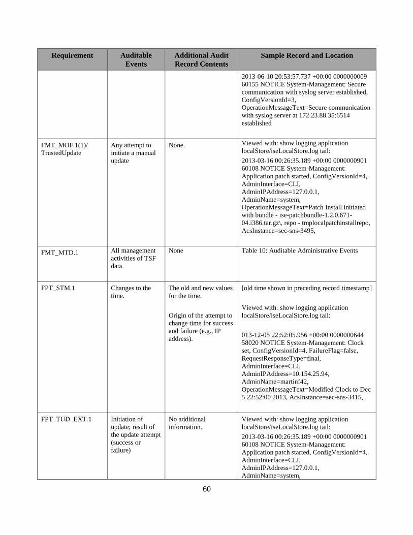
60
Requirement Auditable
Events
Additional Audit
Record Contents
Sample Record and Location
2013-06-10 20:53:57.737 +00:00 0000000009
60155 NOTICE System-Management: Secure
communication with syslog server established,
ConfigVersionId=3,
OperationMessageText=Secure communication
with syslog server at 172.23.88.35:6514
established
FMT_MOF.1(1)/
TrustedUpdate
Any attempt to
initiate a manual
update
None. Viewed with: show logging application
localStore/iseLocalStore.log tail:
2013-03-16 00:26:35.189 +00:00 0000000901
60108 NOTICE System-Management:
Application patch started, ConfigVersionId=4,
AdminInterface=CLI,
AdminIPAddress=127.0.0.1,
AdminName=system,
OperationMessageText=Patch Install initiated
with bundle - ise-patchbundle-1.2.0.671-
04.i386.tar.gz\, repo - tmplocalpatchinstallrepo,
AcsInstance=sec-sns-3495,
FMT_MTD.1 All management
activities of TSF
data.
None Table 10: Auditable Administrative Events
FPT_STM.1 Changes to the
time.
The old and new values
for the time.
Origin of the attempt to
change time for success
and failure (e.g., IP
address).
[old time shown in preceding record timestamp]
Viewed with: show logging application
localStore/iseLocalStore.log tail:
013-12-05 22:52:05.956 +00:00 0000000644
58020 NOTICE System-Management: Clock
set, ConfigVersionId=4, FailureFlag=false,
RequestResponseType=final,
AdminInterface=CLI,
AdminIPAddress=10.154.25.94,
AdminName=martinf42,
OperationMessageText=Modified Clock to Dec
5 22:52:00 2013, AcsInstance=sec-sns-3415,
FPT_TUD_EXT.1 Initiation of
update; result of
the update attempt
(success or
failure)
No additional
information.
Viewed with: show logging application
localStore/iseLocalStore.log tail:
2013-03-16 00:26:35.189 +00:00 0000000901
60108 NOTICE System-Management:
Application patch started, ConfigVersionId=4,
AdminInterface=CLI,
AdminIPAddress=127.0.0.1,
AdminName=system,

61
Requirement Auditable
Events
Additional Audit
Record Contents
Sample Record and Location
OperationMessageText=Patch Install initiated
with bundle - ise-patchbundle-1.2.0.671-
04.i386.tar.gz\, repo - tmplocalpatchinstallrepo,
AcsInstance=sec-sns-3495,
Jul 2 00:55:11 ise3515
CISE_Administrative_and_Operational_Audit
0000000019 1 0 2016-07-02 00:55:11.676
+00:00 0000000067 60126 NOTICE System-
Management: Application patch installation
failed, ConfigVersionId=6,
AdminInterface=GUI,
AdminIPAddress=10.32.2.79,
AdminName=martinf45,
OperationMessageText=Error while trying to
reboot , AcsInstance=ise3515
FTA_SSL_EXT.1 Any attempts at
unlocking of an
interactive
session.
No additional
information.
In the TOE this is represented by login attempts
that occur after the timeout of an administrative
user.
See events for FIA_UIA_EXT.1 above.
FTA_SSL.3 The termination
of a remote
session by the
session locking
mechanism.
No additional
information.
Client-Certificate Authentication Method
Viewed with: show logging application
localStore/iseLocalStore.log tail:
2013-12-11 21:31:21.210 +00:00 0000000204
51003 NOTICE Administrator-Login: Session
Timeout, ConfigVersionId=4,
AdminSession=Session Timedout,
AdminName=internetofeverything@windsurfer
.cisco.com,
Password Authentication Method:
Viewed with: show logging application
localStore/iseLocalStore.log tail:
2013-12-04 23:01:22.143 +00:00 0000000264
51003 NOTICE Administrator-Login: Session
Timeout, ConfigVersionId=4,
AdminSession=Session Timedout,
AdminName=martinf43,
LDAPS to Active Directory External
Authentication Method:
Viewed with: show logging application
localStore/iseLocalStore.log tail:
2013-12-11 23:46:16.071 +00:00 0000000976
51003 NOTICE Administrator-Login: Session

62
Requirement Auditable
Events
Additional Audit
Record Contents
Sample Record and Location
Timeout, ConfigVersionId=4,
AdminSession=Session Timedout,
AdminName=internetofeverything@windsurfer
.cisco.com,
Console:
Viewed with: show logging application
localStore/iseLocalStore.log tail:
013-12-04 23:04:21.278 +00:00 0000000268
60116 NOTICE System-Management: ADEOS
CLI user has logged out, ConfigVersionId=4,
AdminInterface=CLI,
AdminIPAddress=127.0.0.1,
AdminName=system,
OperationMessageText=User martinf43 logged
out, AcsInstance=sec-sns-3495,
FTA_SSL.4 The termination
of an interactive
session.
No additional
information.
Viewed with: show logging application
localStore/iseLocalStore.log tail:
Password based authentication –
2013-02-28 06:15:34.322 +00:00 0000007114
51002 NOTICE Administrator-Login:
Administrator logged off,
ConfigVersionId=117, AdminInterface=GUI,
AdminIPAddress=10.35.88.189,
AdminSession=01DECDD71A846CBEA32B7
A2D0614C891, AdminName=admin43,
OperationMessageText=User logged out,
FTP_ITC.1(1)
FTP_ITC.1(2)
Initiation of the
trusted channel.
Termination of
the trusted
channel.
Failure of the
trusted channel
functions.
Identification of the
initiator and target of
failed trusted channels
establishment attempt.
Initiation of the trusted channel:
Viewed with: show logging application
localStore/iseLocalStore.log tail:
2013-06-10 20:53:57.737 +00:00 0000000009
60155 NOTICE System-Management: Secure
communication with syslog server established,
ConfigVersionId=3,
OperationMessageText=Secure communication
with syslog server at 172.23.88.35:6514
established
See events for FCS_TLSS_EXT.1 above.
FTP_TRP.1 Initiation of the
trusted channel.
Termination of
the trusted
channel.
Identification of the
claimed user identity.
See events for FCS_SSHS_EXT.1 and
FCS_TLSS_EXT.1 above.
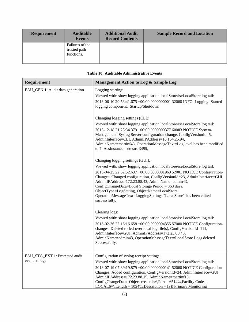
63
Requirement Auditable
Events
Additional Audit
Record Contents
Sample Record and Location
Failures of the
trusted path
functions.
Table 10: Auditable Administrative Events
Requirement Management Action to Log & Sample Log
FAU_GEN.1: Audit data generation Logging starting:
Viewed with: show logging application localStore/iseLocalStore.log tail:
2013-06-10 20:53:41.675 +00:00 0000000001 32000 INFO Logging: Started
logging component, Startup/Shutdown
Changing logging settings (CLI):
Viewed with: show logging application localStore/iseLocalStore.log tail:
2013-12-18 21:23:34.379 +00:00 0000000377 60083 NOTICE System-
Management: Syslog Server configuration change, ConfigVersionId=5,
AdminInterface=CLI, AdminIPAddress=10.154.25.94,
AdminName=martinf43, OperationMessageText=Log level has been modified
to 7, AcsInstance=sec-sns-3495,
Changing logging settings (GUI):
Viewed with: show logging application localStore/iseLocalStore.log tail:
2013-04-25 22:52:52.637 +00:00 0000001963 52001 NOTICE Configuration-
Changes: Changed configuration, ConfigVersionId=23, AdminInterface=GUI,
AdminIPAddress=172.23.88.43, AdminName=admin43,
ConfigChangeData=Local Storage Period = 363 days,
ObjectType=LogSetting, ObjectName=LocalStore,
OperationMessageText=LoggingSettings "LocalStore" has been edited
successfully.
Clearing logs:
Viewed with: show logging application localStore/iseLocalStore.log tail:
2013-02-26 22:16:16.658 +00:00 0000004355 57000 NOTICE Configuration-
changes: Deleted rolled-over local log file(s), ConfigVersionId=111,
AdminInterface=GUI, AdminIPAddress=172.23.88.43,
AdminName=admin43, OperationMessageText=LocalStore Logs deleted
Successfully,
FAU_STG_EXT.1: Protected audit
event storage
Configuration of syslog receipt settings:
Viewed with: show logging application localStore/iseLocalStore.log tail:
2013-07-19 07:39:19.879 +00:00 0000000141 52000 NOTICE Configuration-
Changes: Added configuration, ConfigVersionId=24, AdminInterface=GUI,
AdminIPAddress=172.23.88.15, AdminName=martinf15,
ConfigChangeData=Object created:\\\,Port = 6514\\\,Facility Code =
LOCAL6\\\,Length = 1024\\\,Description = ISE Primary Monitoring

64
Requirement Management Action to Log & Sample Log
Node\\\,Include Alarms = FALSE\\\,Buffer Message = TRUE\\\,Buffer Size =
100\\\,Reconnect Timeout = 30\\\,Certificate = CN=windsurfer-SURFER-AD-
01-CA DC=windsurfer\, DC=cisco\, DC=com\\\,Validation = FALSE\\\,,
ObjectType=LogTarget, ObjectName=PriMonitorTLSSyslog,
OperationMessageText=LoggingTargets "PriMonitorTLSSyslog" has been
created successfully. ,
Viewed with: show logging application localStore/iseLocalStore.log tail:
2013-07-19 07:40:34.489 +00:00 0000000146 52001 NOTICE Configuration-
Changes: Changed configuration, ConfigVersionId=25, AdminInterface=GUI,
AdminIPAddress=172.23.88.15, AdminName=martinf15,
ConfigChangeData=Object modified:\\\, Log Severity Level = INFO\\\,Local
Logging = enable\\\,Assigned Targets =
\{LogCollector\,LogCollector2\,PriMonitorTLSSyslog\},
ObjectType=Category, ObjectName=Administrative and Operational Audit,
OperationMessageText=LoggingCategories "Administrative and Operational
Audit" has been edited successfully.,
Viewed with: show logging application localStore/iseLocalStore.log tail:
2013-07-19 07:47:55.464 +00:00 0000000166 52001 NOTICE Configuration-
Changes: Changed configuration, ConfigVersionId=54, AdminInterface=GUI,
AdminIPAddress=172.23.88.15, AdminName=martinf15,
ConfigChangeData=Object modified:\\\,Port = 20514\\\,Facility Code =
LOCAL6\\\,Length = 1024\\\,Description = Syslog Target for Log
Collector\\\,Include Alarms = FALSE\\\,, ObjectType=LogTarget,
ObjectName=LogCollector, OperationMessageText=LoggingTargets
"LogCollector" has been edited successfully.,
Viewed with: show logging application localStore/iseLocalStore.log tail:
2013-07-19 07:50:35.622 +00:00 0000000167 52001 NOTICE Configuration-
Changes: Changed configuration, ConfigVersionId=68, AdminInterface=GUI,
AdminIPAddress=172.23.88.15, AdminName=martinf15,
ConfigChangeData=Object modified:\\\,Port = 20514\\\,Facility Code =
LOCAL6\\\,Length = 1024\\\,Description = Second Syslog Target for Log
Collector\\\,Include Alarms = FALSE\\\,, ObjectType=LogTarget,
ObjectName=LogCollector2, OperationMessageText=LoggingTargets
"LogCollector2" has been edited successfully.,
FCS_SSHS_EXT.1: SSH Configuration of SSH settings
Viewed with: show logging application localStore/iseLocalStore.log tail:
2013-04-30 01:45:22.396 +00:00 0000002151 60086 NOTICE System-
Management: ADEOS SSH Service configuration change,
ConfigVersionId=4, AdminInterface=CLI, AdminIPAddress=127.0.0.1,
AdminName=admin43, OperationMessageText=Service sshd configuration
has been modified to OFF, AcsInstance=sec-sns-3495,
Viewed with: show logging application localStore/iseLocalStore.log tail:
2013-04-30 01:47:58.033 +00:00 0000002154 60086 NOTICE System-
Management: ADEOS SSH Service configuration change,

65
Requirement Management Action to Log & Sample Log
ConfigVersionId=4, AdminInterface=CLI, AdminIPAddress=127.0.0.1,
AdminName=admin43, OperationMessageText=Service sshd configuration
has been modified to ON, AcsInstance=sec-sns-3495,
Viewed with: show logging application localStore/iseLocalStore.log tail:
2013-12-05 05:37:12.663 +00:00 0000000786 60086 NOTICE System-
Management: ADEOS SSH Service configuration change,
ConfigVersionId=4, AdminInterface=CLI, AdminIPAddress=10.35.88.199,
AdminName=foobar, OperationMessageText=SSHD key-exchange algorithm
has been set to diffie-hellman-group14-sha1, AcsInstance=sec-sns-3495,
FCS_TLSS_EXT.1: TLS Server
Protocol / FCS_TLSC_EXT.1: TLS
Client Protocol
Configuration of TLS: including certificates:
Viewed with: show logging application localStore/iseLocalStore.log tail:
2013-04-23 00:46:51.633 +00:00 0000001071 52000 NOTICE Configuration-
Changes: Added configuration, ConfigVersionId=71,AdminInterface=GUI,
AdminIPAddress=10.34.85.15, AdminName=admin43,
ConfigChangeData=Self-signed certificate was generated\\\, Key Length =
2048\\\, Name = ISE admin Generated Self Signed Certificate for Auditable
Event test case\\\,Use for protocols = HTTPS\\\, Additional details:\\\, Issued
To = sec-sns-3495.cisco.com\\\, Issued By = sec-sns-3495.cisco.com\\\,
Subject = \\\,DC=com\\\,DC=cisco\\\,DC=selfsigned\\\,CN=sec-sns-
3495.cisco.com\\\, Serial Number = 5175d9f800000000811821669147ec5f\\\,
Valid From = Tue Apr 23 00:46:48 UTC 2013\\\, Valid To = Fri Apr 22
00:46:48 UTC 2016, ObjectType=CertificateGeneration,
ObjectName=GenerateCertificate, UserAdminFlag=Admin,
OperatorName=admin43, AcsInstance=sec-sns-3495
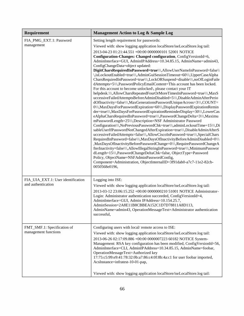
66
Requirement Management Action to Log & Sample Log
FIA_PMG_EXT.1: Password
management
Setting length requirement for passwords:
Viewed with: show logging application localStore/iseLocalStore.log tail:
2013-04-23 01:21:44.551 +00:00 0000000101 52001 NOTICE
Configuration-Changes: Changed configuration, ConfigVersionId=6,
AdminInterface=GUI, AdminIPAddress=10.34.85.15, AdminName=admin43,
ConfigChangeData=object updated:
DigitCharsRequiredInPassword=true\\\,AllowUserNameInPassword=false\\
\,isLockoutEnabled=true\\\,AdminGuiSessionTimeout=60\\\,UpperCaseAlpha
CharsRequiredInPassword=true\\\,LockORSuspend=disable\\\,noOfLoginFaile
dAttempts=5\\\,PasswordPolicyEmailContent=This account has been locked.
For this account to become unlocked\, please contact your IT
helpdesk.\\\,AllowCharsRepeatedFourOrMoreTimesInPassword=true\\\,MaxS
uccessiveFailedAttemptsBeforeAdminDisabled=5\\\,DisableAdminAfterPerio
dOfInactivity=false\\\,MaxGenerationsPasswordUniqueAcross=3\\\,COUNT=
0\\\,MaxDaysForPasswordExpiration=60\\\,DisplayPasswordExpirationRemin
der=true\\\,MaxDaysForPasswordExpirationReminderDisplay=30\\\,LowerCas
eAlphaCharsRequiredInPassword=true\\\,PasswordChangeDelta=3\\\,Maximu
mPasswordLength=25\\\,Description=NSF Administrator Password
Configuration\\\,NoPreviousPasswordChk=true\\\,adminLockoutTime=15\\\,Di
sableUserIfPasswordNotChangedAfterExpiration=true\\\,DisableAdminAfterS
uccessiveFailedAttempts=false\\\,AllowCiscoInPassword=true\\\,SpecialChars
RequiredInPassword=false\\\,MaxDaysOfInactivityBeforeAdminDisabled=0\\\
,MaxDaysOfInactivityBeforePasswordChange=0\\\,RequirePasswordChangeA
fterInactivity=false\\\,AllowIllegalStringInPassword=true\\\,MinimumPasswor
dLength=15\\\,PasswordChangeDeltaChk=false, ObjectType=Password
Policy, ObjectName=NSFAdminPasswordConfig,
Component=Administration, ObjectInternalID=3f91dab0-a7c7-11e2-82cb-
0050568e0196,
FIA_UIA_EXT.1: User identification
and authentication
Logging into ISE:
Viewed with: show logging application localStore/iseLocalStore.log tail:
2013-03-12 23:06:15.252 +00:00 0000000210 51001 NOTICE Administrator-
Login: Administrator authentication succeeded, ConfigVersionId=4,
AdminInterface=GUI, Admin IPAddress=10.154.25.7,
AdminSession=2A8E11B8CBBEA152C1D7D78811A8D113,
AdminName=admin43, OperationMessageText=Administrator authentication
successful,
FMT_SMF.1: Specification of
management functions
Configuring users with local/ remote access to ISE:
Viewed with: show logging application localStore/iseLocalStore.log tail:
2013-06-26 02:17:09.886 +00:00 0000007223 60182 NOTICE System-
Management: RSA key configuration has been modified, ConfigVersionId=56,
AdminInterface=CLI, AdminIPAddress=10.34.85.15, AdminName=foobar,
OperationMessageText=Authorized key
17:75:c5:99:e9:41:78:32:0b:a7:86:c4:0f:8b:4a:c1 for user foobar imported,
AcsInstance=infratest-10-01-pap,
Viewed with: show logging application localStore/iseLocalStore.log tail:

67
Requirement Management Action to Log & Sample Log
2013-06-25 23:37:00.060 +00:00 0000006982 60084 NOTICE System-
Management: ADEOS
CLI user configuration change, ConfigVersionId=56, AdminInterface=CLI,
AdminIPAddress=10.34.85.15, AdminName=admin15,
OperationMessageText=Added user foobar with role: Admin state: Enabled
successfully, AcsInstance=infratest-10-01-pap,
Viewed with: show logging application localStore/iseLocalStore.log tail:
013-06-25 22:09:41.229 +00:00 0000006913 60084 NOTICE System-
Management: ADEOS CLI user configuration change, ConfigVersionId=56,
AdminInterface=CLI, AdminIPAddress=10.34.85.15, AdminName=admin15,
OperationMessageText=Added user clileastprivilege with role: User state:
Enabled successfully, AcsInstance=infratest-10-01-pap,
Configuring the banner displayed prior to authentication:
See FTA_TAB.1 row below.
Configuring any cryptographic functions: See FCS rows above.
FMT_SMR.2: Restrictions on Security
roles
Configuring administrative users with specified roles (Add administrative
user):
Viewed with: show logging application localStore/iseLocalStore.log tail:
2013-03-26 20:23:29.078 +00:00 0000000192 52000 NOTICE Configuration-
Changes: Added configuration, ConfigVersionId=73, AdminInterface=GUI,
AdminIPAddress=10.34.85.13, AdminName=admin43,
ConfigChangeData=object created:
Name=Tnt1666519c\\\,CredentialPassword=*************\\\,isAlarmEmaila
ble=False\\\,Description=for test
Tnt1666519c\\\,SecurID=False\\\,nsfUserTypeRole=ADMIN_ONLY\\\,Lastna
me=1666519c\\\,Firstname=Tnt\\\,isEmailInHtmlFormat=False\\\,AllowPassw
ordChangeAfterLogin=false, ObjectType=Administrators,
ObjectName=Tnt1666519c, Component=Administration,
ObjectInternalID=05495480-9653-11e2-ab0f-5057a8e1cdac,
Configuring administrative users with specified roles (Delete administrative
user):
Viewed with: show logging application localStore/iseLocalStore.log tail:
2013-03-26 22:41:44.525 +00:00 0000000310 52002 NOTICE Configuration-
Changes: Deleted configuration, ConfigVersionId=73, AdminInterface=GUI,
AdminIPAddress=10.34.85.13, AdminName=admin43,
ConfigChangeData=object deleted: Name=Tnt1666519c,
ObjectType=Administrators, ObjectName=Tnt1666519c,
Component=Administration, ObjectInternalID=05495480-9653-11e2-ab0f-
5057a8e1cdac,
FPT_STM.1: Reliable time stamps
Manual changes to the system time:
Viewed with: show logging application localStore/iseLocalStore.log tail:

68
Requirement Management Action to Log & Sample Log
013-12-05 22:52:05.956 +00:00 0000000644 58020 NOTICE System-
Management: Clock set, ConfigVersionId=4, FailureFlag=false,
RequestResponseType=final, AdminInterface=CLI,
AdminIPAddress=10.154.25.94, AdminName=martinf42,
OperationMessageText=Modified Clock to Dec 5 22:52:00 2013,
AcsInstance=sec-sns-3415,
FPT_TUD_EXT.1: Trusted update Software updates:
Viewed with: show logging application localStore/iseLocalStore.log tail:
2013-03-16 00:26:36.194 +00:00 0000000902 60154 NOTICE System-
Management: Application patch install has completed successfully,
ConfigVersionId=4, AdminInterface=CLI, AdminIPAddress=127.0.0.1,
AdminName=system, OperationMessageText=Patch (04) installation
successful, AcsInstance=sec-sns-3495,
Viewed with: show logging application localStore/iseLocalStore.log tail:
2013-03-16 00:26:35.189 +00:00 0000000901 60108 NOTICE System-
Management: Application patch started, ConfigVersionId=4,
AdminInterface=CLI, AdminIPAddress=127.0.0.1, AdminName=system,
OperationMessageText=Patch Install initiated with bundle - ise-patchbundle-
1.2.0.671-04.i386.tar.gz\, repo - tmplocalpatchinstallrepo, AcsInstance=sec-
sns-3495,
FTA_SSL_EXT.1: TSF-initiated
session locking
Setting the console timeout value:
Viewed with: show logging application localStore/iseLocalStore.log tail:
0000000106 1 0 2013-12-18 20:42:55.388 +00:00 0000000347 60189
NOTICE System-Management: Terminal Session timeout has been modified,
ConfigVersionId=4, AdminInterface=CLI, AdminIPAddress=10.154.25.94,
AdminName=martinf43, OperationMessageText=Terminal session-timeout is
set to 0, AcsInstance=sec-sns-3495,
FTA_SSL.3: TSF-initiated termination Setting GUI timeout value:
Viewed with: show logging application localStore/iseLocalStore.log tail:
2013-04-17 08:29:52.562 +00:00 0000000529 52001 NOTICE Configuration-
Changes: Changed configuration, ConfigVersionId=4, AdminInterface=GUI,
AdminIPAddress=10.35.88.238, AdminName=admin43,
ConfigChangeData=object updated:
SessionTimeout=7,ObjectType=SessionTimeout,
ObjectName=SessionTimeout,
Component=Administration,ObjectInternalID=9f542b60-a290-11e2-8c31-
0050568e0196,
2013-07-12T20:12:38.066693+00:00 infratest-10-01-pap ADE-
SERVICE[3947]: [29669]:[info] utils: cars_shellcfg.c[53] [admin15]: Invoked
carsSetConsoleIdleSessionTimeout timeout=3
Viewed with: show logging system ade/ADE.log tail:

69
Requirement Management Action to Log & Sample Log
2013-07-12T20:12:38.066998+00:00 infratest-10-01-pap ADE-
SERVICE[3947]: [29669]:[info] utils: vsh_root_stubs.c[2122] [admin15]:
terminal session-timeout set success
FTA_SSL.4: User-initiated termination Viewed with: show logging application localStore/iseLocalStore.log tail:
2013-02-28 06:15:34.322 +00:00 0000007114 51002 NOTICE Administrator-
Login: Administrator logged off, ConfigVersionId=117, AdminInterface=GUI,
AdminIPAddress=10.35.88.189,
AdminSession=01DECDD71A846CBEA32B7A2D0614C891,
AdminName=admin43, OperationMessageText=User logged out,
Viewed with: show logging application localStore/iseLocalStore.log tail:
2013-12-05 02:25:40.076 +00:00 0000000631 60116 NOTICE System-
Management: ADEOS CLI user has logged out, ConfigVersionId=4,
AdminInterface=CLI, AdminIPAddress=127.0.0.1, AdminName=system,
OperationMessageText=User martinf43 logged out, AcsInstance=sec-sns-
3495,
FTA_TAB.1: Default TOE access
banners
Configuring the GUI banner displayed prior to authentication:
Viewed with: show logging application localStore/iseLocalStore.log tail:
2013-05-22 05:31:40.143 +00:00 0000000441 52000 NOTICE Configuration-
Changes: Added configuration, ConfigVersionId=27, AdminInterface=GUI,
AdminIPAddress=10.21.169.61, AdminName=martinf15,
ObjectType=GUIPreLoginBanner, ObjectName=GUIPreLoginBanner,
OperationMessageText=GUI Pre login banner has been configured,
AcsInstance=infratest-10-01-pap,
Configuring the CLI banner displayed prior to authentication:
Viewed with: show logging application localStore/iseLocalStore.log tail:
2013-05-22 05:31:40.424 +00:00 0000000442 52000 NOTICE Configuration-
Changes: Added configuration, ConfigVersionId=27, AdminInterface=GUI,
AdminIPAddress=10.21.169.61, AdminName=martinf15,
ObjectType=CLIPreLoginBanner, ObjectName=CLIPreLoginBanner,
OperationMessageText=CLI Pre login banner has been configured,
AcsInstance=infratest-10-01-pap,
FTP_TRP.1: Trusted path Connecting to ISE with HTTPS:
Viewed with: show logging application localStore/iseLocalStore.log tail:
2013-03-12 23:06:15.252 +00:00 0000000210 51001 NOTICE Administrator-
Login: Administrator authentication succeeded, ConfigVersionId=4,
AdminInterface=GUI, Admin IPAddress=10.154.25.7,
AdminSession=2A8E11B8CBBEA152C1D7D78811A8D113,
AdminName=admin43, OperationMessageText=Administrator authentication
successful
Connecting to ISE with SSH:
Viewed with: show logging application localStore/iseLocalStore.log tail:

70
Requirement Management Action to Log & Sample Log
2013-07-18 21:34:15.419 +00:00 0000001210 60080 NOTICE Administrator-
Login: A SSH CLI user has successfully logged in, ConfigVersionId=5,
AdminInterface=CLI, OperationMessageText=Accepted password for
martinf43 from 10.21.167.148 port 8836 ssh2, AcsInstance=sec-sns-3495,
5.1 Viewing Audit Records
From Command Line Interface:
1. Successfully authenticate to the Command Line Interface (CLI) as an admin-role user.
2. Run the command shown above each sample log in Table 10 and 11 above (i.e. ‘show
logging application localStore/iseLocalStore.log tail’).
From the Administration GUI:
The iseLocalStore.log can be remotely downloaded by running the following steps:
1. Successfully authenticate to the Administration GUI as a SuperAdmin role user.
2. Navigate to the Menu: Operations > Download Logs

71
3. On the left-side navigate to the ISE node where the audit event was generated in
iseLocalStore.log:
4. Click the ‘Debug Logs’ tab in the content area:

72
5. Scroll down the list of log files until the iseLocalStore.log filename appears. Click on the
iseLocalStore.log link.

73
6. The iseLocalStore.log file may be downloaded or viewed with any external program.
5.2 Deleting Audit Records
5.2.1 Local Logs Storage Settings and Deletion
From the Administration > System > Logging > Local Log Settings page a System admin or a
Super admin is able to configure the storage period for logs in days and delete the existing log
file. The administrator may delete all of the rolled over log files by the "Delete Local Logs Now"
selection in the administration application.
After the configured storage period of time has passed for logs the events exceeding the age are
automatically deleted.
TCP syslog buffers events in a local file that is limited to a total of 100MB. The limit is specified
as a file size, not a specific number of events. Overwriting is handled by wrapping to the
beginning of the file (overwriting the oldest events). The value of 100MB is configurable and the

74
lowest value for the configuration is 10 MB and the allowed increments need to be whole
numbers.
5.2.2 External Platform Logs Storage Settings and Deletion
Logs received from external platforms, including other iterations of ISE, are stored in the M&T
(Monitoring and Troubleshooting) log on the ISE platform. To configure log storage settings and
clear these logs, login to the command line interface (CLI) of the ISE Monitoring persona node
as an admin-role user. Then run the EXEC level command application configure ise followed
by entering selection 9 to Purge M&T Operational Data. Then enter any legal number of days to
retain data (1-90) and confirm request with y (yes) response. See example below for context.
hostname/username# application configure ise
Selection ISE configuration option
[1]Reset Active Directory settings to defaults
[2]Display Active Directory settings
[3]Configure Active Directory settings
[4]Restart/Apply Active Directory settings
[5]Clear Active Directory Trusts Cache and restart/apply
Active Directory settings
[6]Enable/Disable ERS API
[7]Reset M&T Session Database
[8]Rebuild M&T Unusable Indexes
[9]Purge M&T Operational Data
[10]Reset M&T Database
[11]Refresh M&T Database Statistics
[12]Display Profiler Statistics
[13]Exit
9
Enter number of days to be retained in purging MnT
Operational data [between 1 to 90 days]
For instance, Entering 20 will purge MnT Operational data
older than 20 days
Enter 'exit' to return to the main menu without purging
Enter days to be retained: 90
You are about to purge M&T data older than 90 from your
database.

75
Are you sure you want to proceed? y/n [n]: y
M&T Operational data older than 90 is getting removed from
database

76
6. Modes of Operation An ISE has several modes of operation, these modes are as follows:
Booting – while booting, ISE drops all network traffic until the image and configuration has
loaded. This mode of operation automatically progresses to the Normal mode of operation. If a
special image has been loaded on the system (as received from Cisco TAC), then the system
goes from booting to Rescue Admin CLI.
Rescue Admin CLI - booting to the rescue admin CLI password recovery image (on an image
received from Cisco TAC) allows modification of a CLI administrator user in the event the
password is forgotten. Once the password is reset, the ISE reloads and enters booting mode.
Safe Mode – Once ISE has booted, a CLI admin-role user can put the device into Safe Mode by
issuing the following commands: ‘applicaton stop ise’ followed by ‘application start ise safe’.
This "safe mode" exists in the event a customer misconfigures their access controls that prevents
them from being able to administer ISE from the Administration console GUI. Once the
configuration has been corrected in safe mode, the ISE reloads and enters booting mode.
Normal - The ISE image and configuration is loaded and the TOE is operating as configured. It
should be noted that all levels of administrative access occur in this mode and that all ISE based
security functions are operating. This is the expected mode of operation for the TOE.
Following operational error ISE reboots (once power supply is available) and enters booting
mode.
ISE also has two modes of operation in respect to cryptographic functionality:
Non-FIPS mode – The TOE ships in non-FIPS mode, which does not place any restrictions on
the cryptography used on the system.
FIPS mode – In FIPS mode, the ISE utilizes the cryptography described in [ [5] for all claimed
cryptographic operations. When FIPS mode is enabled, the Cisco ISE administrator interface
displays a FIPS mode icon to the left of the node name in the upper-right of the page. Along with
Normal mode, this is the expected mode of operation for the TOE.
ISE uses a cryptographic module, that runs a suite of self-tests during the TOE initial start-up to
verify its correct operation. These tests check the integrity of the code, and the correct operation
of each cryptographic algorithm and method used (i.e. AES-CBC, SHA-1, etc.) If any of the tests
fail, the administrative web-based UI will not be accessible, and the security administrator will
for a limited time window be able to login to the CLI on the KVM (keyboard, video, mouse)
console to run the CLI command – “show application status ise” to determine that services have
been disabled because “FIPS INTEGRITY CHECK HAS FAILED”. Eventually the
administrator will be unable to login to the CLI even on the KVM as all services are shutdown
including the ability to login to the CLI. After authenticating, a fatal error is displayed and the
user is only allowed to press <Enter> to logout and no other actions can be performed. The error
message is: “ERROR: ISE SERVICES HAVE BEEN DISABLED BECAUSE FIPS

77
INTEGRITY CHECK HAS FAILED! EITHER REIMAGE FROM ISE INSTALLATION
MEDIA, OR CONTACT CISCO TECHNICAL SUPPORT CENTER FOR INSTRUCTIONS
ON DIAGNOSING THE FAILURE. Press <Enter> to logout”.

78
7. Security Measures for the Operational Environment
Proper operation of the TOE requires functionality from the environment. It is the responsibility
of the Security administrator of the TOE to ensure that the Operational Environment provides the
necessary functions, and adheres to the environment security objectives listed below. The
environment security objective identifiers map to the environment security objectives as defined
in the Security Target.
Table 11: Operational Environment Security Measures
Environment Security
Objective
Operational Environment
Security Objective Definition
Privileged and Semi-privileged
administrator responsibility
OE.PHYSICAL Physical security, commensurate
with the value of the TOE and the
data it contains, is provided by the
environment.
Administrators must ensure the TOE is
installed and maintained within a secure
physical location. This can include a
secured building with key card access or
within the physical control of an
authorized administrator in a mobile
environment.
OE.NO_GENERAL_PURPOSE There are no general-purpose
computing capabilities (e.g.,
compilers or user applications)
available on the TOE, other than
those services necessary for the
operation, administration and
support of the TOE.
Administrators will make sure there are
no general-purpose computing
capabilities (e.g., compilers or user
applications) available on the TOE.
OE.NO_THRU_TRAFFIC_PROT
ECTION
The TOE does not provide any
protection of traffic that traverses
it. It is assumed that protection of
this traffic will be covered by
other security and assurance
measures in the operational
environment.
Administrators need to ensure that the
security provided by the TOE is
complemented by other security
measures in the operational environment
that provides protection to the traffic
traversing the TOE.
OE.TRUSTED_ADMIN TOE Administrators are trusted to
follow and apply all administrator
guidance in a trusted manner.
Administrators must be properly trained
in the usage and proper operation of the
TOE and all the provided functionality
per the implementing organization’s
operational security policies. These
administrators must follow the provided
guidance.

79
Environment Security
Objective
Operational Environment
Security Objective Definition
Privileged and Semi-privileged
administrator responsibility
OE.UPDATES The TOE firmware and software
is updated by an administrator on
a regular basis in response to the
release of product updates due to
known vulnerabilities.
Administrators ensure that the TOE is
updated with the latest firmware and
software patches to keep it secure from
threats to known vulnerabilities.
OE.ADMIN_CREDENTIALS_S
ECURE
The administrator’s credentials
(private key) used to access the
TOE must be protected on any
other platform on which they
reside.
Administrators need to ensure to keep
their credentials used to access the TOE,
secure and protected

80
8. Related Documentation Use this document in conjunction with the ISE 2.0 documentation at the following
location:
• http://www.cisco.com/
Obtaining Documentation
The following sections provide sources for obtaining documentation from Cisco Systems.
8.1 World Wide Web
You can access the most current Cisco documentation on the World Wide Web at the
following sites:
• http://www.cisco.com
• http://www-china.cisco.com
• http://www-europe.cisco.com
8.2 Ordering Documentation
Cisco documentation is available in the following ways:
Registered Cisco Direct Customers can order Cisco Product documentation from the
Networking Products MarketPlace:
http://www.cisco.com/web/ordering/root/index.html
Registered Cisco.com users can order the Documentation CD-ROM through the online
Subscription Store:
http://www.cisco.com/go/subscription
Non-registered Cisco.com users can order documentation through a local account
representative by calling Cisco corporate headquarters (California, USA) at 408 526-
7208 or, in North America, by calling 800 553-NETS (6387).
8.3 Documentation Feedback
If you are reading Cisco product documentation on the World Wide Web, you can submit
technical comments electronically. Click Feedback in the toolbar and select
Documentation. After you complete the form, click Submit to send it to Cisco.
You can e-mail your comments to [email protected].
To submit your comments by mail, for your convenience many documents contain a
response card behind the front cover. Otherwise, you can mail your comments to the
following address:

81
Cisco Systems, Inc., Document Resource Connection
170 West Tasman Drive
San Jose, CA 95134-9883
We appreciate your comments.
9. Obtaining Technical Assistance Cisco provides Cisco.com as a starting point for all technical assistance. Customers and
partners can obtain documentation, troubleshooting tips, and sample configurations from
online tools. For Cisco.com registered users, additional troubleshooting tools are
available from the TAC website.
Cisco.com is the foundation of a suite of interactive, networked services that provides
immediate, open access to Cisco information and resources at anytime, from anywhere in
the world. This highly integrated Internet application is a powerful, easy-to-use tool for
doing business with Cisco.
Cisco.com provides a broad range of features and services to help customers and partners
streamline business processes and improve productivity. Through Cisco.com, you can
find information about Cisco and our networking solutions, services, and programs. In
addition, you can resolve technical issues with online technical support, download and
test software packages, and order Cisco learning materials and merchandise. Valuable
online skill assessment, training, and certification programs are also available.
Customers and partners can self-register on Cisco.com to obtain additional personalized
information and services. Registered users can order products, check on the status of an
order, access technical support, and view benefits specific to their relationships with
Cisco.
To access Cisco.com, go to the following website:
http://www.cisco.com