Cisco HyperFlex HX-E-220M5SX Edge Spec Sheet · 2018-05-18 · Cisco HyperFlex HX-E-220M5SX Edge...
50
CISCO SYSTEMS PUBLICATION HISTORY 170 WEST TASMAN DR SAN JOSE, CA, 95134 REV A.2 APRIL 14, 2018 WWW.CISCO.COM Spec Sheet Cisco HyperFlex HX-E-220M5SX Edge Node
Transcript of Cisco HyperFlex HX-E-220M5SX Edge Spec Sheet · 2018-05-18 · Cisco HyperFlex HX-E-220M5SX Edge...

CISCO SYSTEMS PUBLICATION HISTORY170 WEST TASMAN DRSAN JOSE, CA, 95134 REV A.2 APRIL 14, 2018 WWW.CISCO.COM
Spec Sheet
Cisco HyperFlex
HX-E-220M5SX Edge Node

Cisco HyperFlex HX-E-220M5SX Edge Node2
OVERVIEW . . . . . . . . . . . . . . . . . . . . . . . . . . . . . . . . . . . . . . . . . . . . . . . 3DETAILED VIEWS . . . . . . . . . . . . . . . . . . . . . . . . . . . . . . . . . . . . . . . . . . . 4
Chassis Front View . . . . . . . . . . . . . . . . . . . . . . . . . . . . . . . . . . . . . . . . . . . . . . . . . . .4Chassis Rear View . . . . . . . . . . . . . . . . . . . . . . . . . . . . . . . . . . . . . . . . . . . . . . . . . . .5
BASE NODE STANDARD CAPABILITIES and FEATURES . . . . . . . . . . . . . . . . . . 6CONFIGURING the HyperFlex HX-E-220M5SX Edge Node . . . . . . . . . . . . . . . . 9
STEP 1 VERIFY SERVER SKU . . . . . . . . . . . . . . . . . . . . . . . . . . . . . . . . . . . . . . . . . . . 10STEP 2 SELECT CPU(s) . . . . . . . . . . . . . . . . . . . . . . . . . . . . . . . . . . . . . . . . . . . . . . 11STEP 3 SELECT MEMORY . . . . . . . . . . . . . . . . . . . . . . . . . . . . . . . . . . . . . . . . . . . . . 13STEP 4 SELECT RAID CONTROLLER . . . . . . . . . . . . . . . . . . . . . . . . . . . . . . . . . . . . . . 16SAS HBA (internal HDD/SSD/JBOD support) . . . . . . . . . . . . . . . . . . . . . . . . . . . . . . . . . . 16STEP 5 SELECT DRIVES . . . . . . . . . . . . . . . . . . . . . . . . . . . . . . . . . . . . . . . . . . . . . . 17STEP 6 SELECT PCIe OPTION CARD(s) . . . . . . . . . . . . . . . . . . . . . . . . . . . . . . . . . . . . 19STEP 7 ORDER POWER SUPPLY . . . . . . . . . . . . . . . . . . . . . . . . . . . . . . . . . . . . . . . . . 20STEP 8 SELECT POWER CORD(s) . . . . . . . . . . . . . . . . . . . . . . . . . . . . . . . . . . . . . . . . 21STEP 9 SELECT ACCESSORIES . . . . . . . . . . . . . . . . . . . . . . . . . . . . . . . . . . . . . . . . . . 24STEP 10 ORDER TOOL-LESS RAIL KIT AND OPTIONAL REVERSIBLE CABLE MANAGEMENT ARM . 25STEP 11 SELECT OPERATING SYSTEM AND VALUE-ADDED SOFTWARE . . . . . . . . . . . . . . . . 26STEP 12 SELECT SERVICE and SUPPORT LEVEL . . . . . . . . . . . . . . . . . . . . . . . . . . . . . . 27
OPTIONAL STEP - ORDER RACK(s) . . . . . . . . . . . . . . . . . . . . . . . . . . . . . . 32OPTIONAL STEP - ORDER PDU . . . . . . . . . . . . . . . . . . . . . . . . . . . . . . . . . 33SUPPLEMENTAL MATERIAL . . . . . . . . . . . . . . . . . . . . . . . . . . . . . . . . . . . 34
Supported Network Topologies for HyperFlex Edge Deployments . . . . . . . . . . . . . . . . . . . 34Single Switch Configuration . . . . . . . . . . . . . . . . . . . . . . . . . . . . . . . . . . . . . . . . 34Dual Switch Configuration . . . . . . . . . . . . . . . . . . . . . . . . . . . . . . . . . . . . . . . . . 35
CHASSIS . . . . . . . . . . . . . . . . . . . . . . . . . . . . . . . . . . . . . . . . . . . . . . . . . . . . . . . . . 36Block Diagram . . . . . . . . . . . . . . . . . . . . . . . . . . . . . . . . . . . . . . . . . . . . . . . . . . . . . 37Serial Port Details . . . . . . . . . . . . . . . . . . . . . . . . . . . . . . . . . . . . . . . . . . . . . . . . . . 38Upgrade and Servicing-Related Parts . . . . . . . . . . . . . . . . . . . . . . . . . . . . . . . . . . . . . . 39RACKS . . . . . . . . . . . . . . . . . . . . . . . . . . . . . . . . . . . . . . . . . . . . . . . . . . . . . . . . . . 40PDUs . . . . . . . . . . . . . . . . . . . . . . . . . . . . . . . . . . . . . . . . . . . . . . . . . . . . . . . . . . . 41KVM CABLE . . . . . . . . . . . . . . . . . . . . . . . . . . . . . . . . . . . . . . . . . . . . . . . . . . . . . . . 42
TECHNICAL SPECIFICATIONS . . . . . . . . . . . . . . . . . . . . . . . . . . . . . . . . . . 43Dimensions and Weight . . . . . . . . . . . . . . . . . . . . . . . . . . . . . . . . . . . . . . . . . . . . . . . 43Power Specifications . . . . . . . . . . . . . . . . . . . . . . . . . . . . . . . . . . . . . . . . . . . . . . . . 44Environmental Specifications . . . . . . . . . . . . . . . . . . . . . . . . . . . . . . . . . . . . . . . . . . . 47Extended Operating Temperature Hardware Configuration Limits . . . . . . . . . . . . . . . . . . . 48Compliance Requirements . . . . . . . . . . . . . . . . . . . . . . . . . . . . . . . . . . . . . . . . . . . . . 49

OVERVIEW
OVERVIEWCisco HyperFlex™ Systems provides an all-purpose virtualized server platform, with hypervisor hosts, networking connectivity, and virtual server storage across a set of Cisco UCS HX-Series x86 rack-mount servers. It combines the convergence of computing and networking provided by Cisco UCS, along with next-generation hyperconverged storage software, to uniquely provide the compute resources, network connectivity, storage, and hypervisor platform to run an entire virtual environment, all contained in a single uniform system.
Cisco HyperFlex Edge System is an entry level Cisco HyperFlex system which is optimized for remote sites, branch offices, and edge environments. As a smaller form factor of Cisco hyperconverged solution, Cisco HyperFlex Edge keeps the full power of next generation hyperconverged platform even without connecting to Cisco UCS Fabric Interconnects. Cisco HyperFlex Edge Systems support a fixed configuration of three HX converged nodes but allow the ability to scale up capacity by hot-adding additional capacity drives.
HyperFlex Edge operates using existing top of rack 1Gb switching with options for both single and dual switch configurations. Edge clusters are configured with replication factor 2 (RF2) to ensure availability during various failure scenarios. HyperFlex Edge is typically deployed in environments with a minimal infrastructure footprint, hence the use of UCS compute-only nodes is not supported.
The Cisco HyperFlex HX-E-220M5SX Edge Node is shown in Figure 1.
The HX-E-220M5SX Edge servers extend the capabilities of Cisco’s HyperFlex portfolio in a 1U form factor with the addition of the Intel® Xeon® Processor Scalable Family, 24 DIMM slots for 2666MHz DIMMs, up to 128GB individual DIMM capacities and up to 3.0TB of total DRAM capacities!
Figure 1 Cisco HyperFlex HX-E-220M5SX Edge Node
Front View
Rear View
Cisco HyperFlex HX-E-220M5SX Edge Node 3
DETAILED VIEWS
DETAILED VIEWS
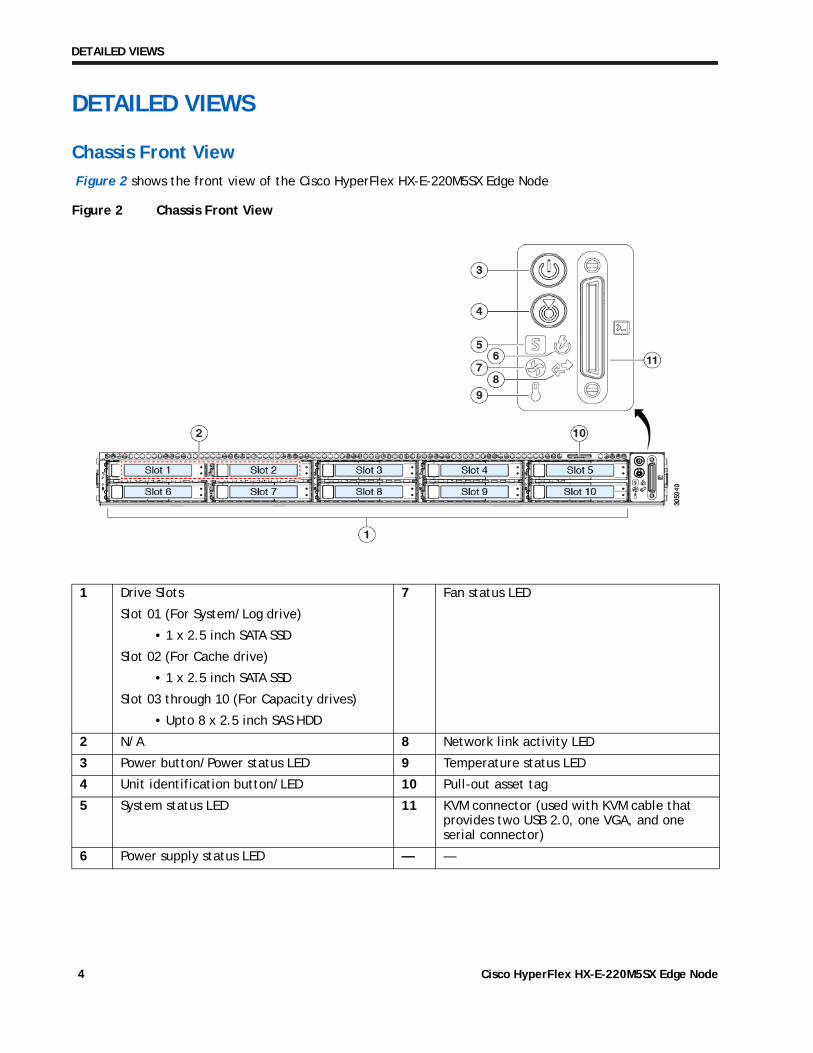
Chassis Front View
Figure 2 shows the front view of the Cisco HyperFlex HX-E-220M5SX Edge Node
Figure 2 Chassis Front View
1 Drive Slots
Slot 01 (For System/Log drive)
Slot 02 (For Cache drive)
Slot 03 through 10 (For Capacity drives)
7 Fan status LED
2 N/A 8 Network link activity LED
3 Power button/Power status LED 9 Temperature status LED
4 Unit identification button/LED 10 Pull-out asset tag
5 System status LED 11 KVM connector (used with KVM cable that provides two USB 2.0, one VGA, and one serial connector)
6 Power supply status LED — —
• 1 x 2.5 inch SATA SSD
• 1 x 2.5 inch SATA SSD
• Upto 8 x 2.5 inch SAS HDD
Cisco HyperFlex HX-E-220M5SX Edge Node4
DETAILED VIEWS
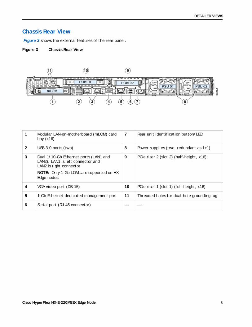
Chassis Rear View
Figure 3 shows the external features of the rear panel.
Figure 3 Chassis Rear View
1 Modular LAN-on-motherboard (mLOM) card bay (x16)
7 Rear unit identification button/LED
2 USB 3.0 ports (two) 8 Power supplies (two, redundant as 1+1)
3 Dual 1/10-Gb Ethernet ports (LAN1 and LAN2). LAN1 is left connector andLAN2 is right connector
NOTE: Only 1-Gb LOMs are supported on HX Edge nodes.
9 PCIe riser 2 (slot 2) (half-height, x16);
4 VGA video port (DB-15) 10 PCIe riser 1 (slot 1) (full-height, x16)
5 1-Gb Ethernet dedicated management port 11 Threaded holes for dual-hole grounding lug
6 Serial port (RJ-45 connector) — —
Cisco HyperFlex HX-E-220M5SX Edge Node 5

BASE NODE STANDARD CAPABILITIES and FEATURES
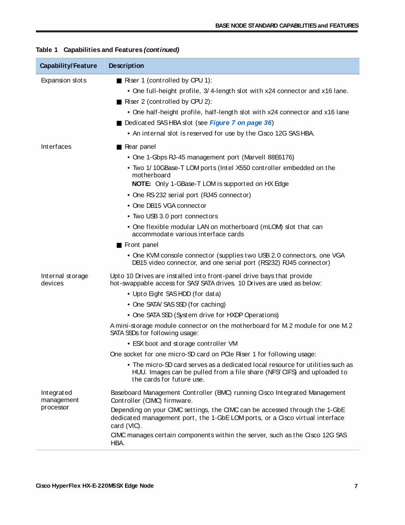
BASE NODE STANDARD CAPABILITIES and FEATURESTable 1 lists the capabilities and features of the base server. Details about how to configure the server for a particular feature or capability (for example, number of processors, disk drives, or amount of memory) are provided in CONFIGURING the HyperFlex HX-E-220M5SX Edge Node, page 9.
Table 1 Capabilities and Features
Capability/Feature Description
Chassis One rack unit (1RU) chassis
CPU One or two Intel® Xeon® processor scalable family CPUs
Chipset Intel® C620 series chipset
Memory 24 slots for registered DIMMs (RDIMMs) or load-reduced DIMMs (LRDIMMs), or through silicon via (TSV) DIMMs
Multi-bit Error Protection
This server supports multi-bit error protection.
Video The Cisco Integrated Management Controller (CIMC) provides video using the ASPEED Pilot 4 video/graphics controller:
Integrated 2D graphics core with hardware acceleration
DDR4 memory interface supports up to 16 MB directly accessible from host and entire DDR memory indirectly accessible from host processor.
Supports all display resolutions up to 1920 x 1200 x 32bpp resolution at 60Hz
High-speed integrated 24-bit RAMDAC
Single lane PCI-Express host interface
eSPI processor to BMC support
Power subsystem Up to two of the following hot-swappable power supplies:
770 W (AC)
1050 W (AC)
1050 W (DC)
One power supply is mandatory; one more can be added for 1 + 1 redundancy.
WoL The Intel x550 10G Base-T Ethernet LAN ports support the wake-on-LAN (WoL) standard.
Front Panel A front panel controller provides status indications and control buttons
ACPI This server supports the advanced configuration and power interface (ACPI) 4.0 standard.
Fans Seven hot-swappable fans for front-to-rear cooling
Cisco HyperFlex HX-E-220M5SX Edge Node6
BASE NODE STANDARD CAPABILITIES and FEATURES
Expansion slots Riser 1 (controlled by CPU 1):
• One full-height profile, 3/4-length slot with x24 connector and x16 lane.
Riser 2 (controlled by CPU 2):
• One half-height profile, half-length slot with x24 connector and x16 lane
Dedicated SAS HBA slot (see Figure 7 on page 36)
• An internal slot is reserved for use by the Cisco 12G SAS HBA.
Interfaces Rear panel
• One 1-Gbps RJ-45 management port (Marvell 88E6176)
• Two 1/10GBase-T LOM ports (Intel X550 controller embedded on the motherboardNOTE: Only 1-GBase-T LOM is supported on HX Edge
• One RS-232 serial port (RJ45 connector)
• One DB15 VGA connector
• Two USB 3.0 port connectors
• One flexible modular LAN on motherboard (mLOM) slot that can accommodate various interface cards
Front panel
• One KVM console connector (supplies two USB 2.0 connectors, one VGA DB15 video connector, and one serial port (RS232) RJ45 connector)
Internal storage devices
Upto 10 Drives are installed into front-panel drive bays that provide hot-swappable access for SAS/SATA drives. 10 Drives are used as below:
• Upto Eight SAS HDD (for data)
• One SATA/SAS SSD (for caching)
• One SATA SSD (System drive for HXDP Operations)
A mini-storage module connector on the motherboard for M.2 module for one M.2 SATA SSDs for following usage:
• ESX boot and storage controller VM
One socket for one micro-SD card on PCIe Riser 1 for following usage:
• The micro-SD card serves as a dedicated local resource for utilities such as HUU. Images can be pulled from a file share (NFS/CIFS) and uploaded to the cards for future use.
Integrated management processor
Baseboard Management Controller (BMC) running Cisco Integrated Management Controller (CIMC) firmware.Depending on your CIMC settings, the CIMC can be accessed through the 1-GbE dedicated management port, the 1-GbE LOM ports, or a Cisco virtual interface card (VIC).CIMC manages certain components within the server, such as the Cisco 12G SAS HBA.
Table 1 Capabilities and Features (continued)
Capability/Feature Description
Cisco HyperFlex HX-E-220M5SX Edge Node 7

BASE NODE STANDARD CAPABILITIES and FEATURES
Storage controller Cisco 12G SAS HBA (JBOD/Pass-through Mode)
• Supports up to 10 SAS/SATA internal drives
• Plugs into the dedicated RAID controller slot
PCIe option card The PCIe slot 1 on the motherboard can flexibly accommodate the follow card:
Cisco 1387 Virtual Interface Cards
Quad Port Intel i350
NOTE: Use of VIC1387 for 10GbE networking requires RPQ approval from the HyperFlex BU.NOTE: When approved under RPQ, VIC1387 must be ordered with two Cisco QSA modules.
Table 1 Capabilities and Features (continued)
Capability/Feature Description
Cisco HyperFlex HX-E-220M5SX Edge Node8

CONFIGURING the HyperFlex HX-E-220M5SX Edge Node
CONFIGURING the HyperFlex HX-E-220M5SX Edge NodeFor the most part, this system comes with a fixed configuration. Use these steps to see or change the configuration of the Cisco HX-E-220M5SX Edge Node:
STEP 1 VERIFY SERVER SKU, page 10
STEP 2 SELECT CPU(s), page 11
STEP 3 SELECT MEMORY, page 13
STEP 4 SELECT RAID CONTROLLER, page 16
STEP 5 SELECT DRIVES, page 17
STEP 6 SELECT PCIe OPTION CARD(s), page 19
STEP 7 ORDER POWER SUPPLY, page 20
STEP 8 SELECT POWER CORD(s), page 21
STEP 9 SELECT ACCESSORIES, page 24
STEP 10 ORDER TOOL-LESS RAIL KIT AND OPTIONAL REVERSIBLE CABLE MANAGEMENT ARM, page 25
STEP 11 SELECT OPERATING SYSTEM AND VALUE-ADDED SOFTWARE, page 26
STEP 12 SELECT SERVICE and SUPPORT LEVEL, page 27
OPTIONAL STEP - ORDER RACK(s), page 32
OPTIONAL STEP - ORDER PDU, page 33
Cisco HyperFlex HX-E-220M5SX Edge Node 9

CONFIGURING the HyperFlex HX-E-220M5SX Edge Node
STEP 1 VERIFY SERVER SKU
Verify the product ID (PID) of the server as shown in Table 2.
Table 2 PID of the HX-E-220M5SX Edge Node
Product ID (PID) Description
HX-E-220M5SX1 HX220c M5 Edge Node, with one or two CPUs, memory, up to eight HDDs for data storage, one SSD (HyperFlex system drive), one SSD for caching, one or two power supplies, one M.2 SATA SSD, one micro-SD card, optional PCIe cards, and optional rail kit.
HX-E-M5S-HXDP This major line bundle (MLB) consists of the Server Node (HX-E-220M5SX) with HXDP software spare PIDs.
The HX-E-220M5SX Edge Node:
• Requires configuration of upto two power supplies, upto two CPUs, recommended memory sizes, 1 SSD for Caching, 1 SSD for system logs, upto 8 data HDDs, 1 M.2 SATA SSD and 1 micro-SD card.
•
NOTE: Use the steps on the following pages to configure the server with the components that you want to include.
Provides option to choose 10G QSAs when operating in 10GbE mode under RPQ.
Notes:
1. This product may not be purchased outside of the approved bundles (must be ordered under the MLB HX-E-M5S-HXDP).
Cisco HyperFlex HX-E-220M5SX Edge Node10

CONFIGURING the HyperFlex HX-E-220M5SX Edge Node
STEP 2 SELECT CPU(s)
The standard CPU features are:
Intel® Xeon® processor scalable family CPUs
Intel C620 series chipset
Cache size of up to 38.5 MB
Select CPUs
The available CPUs are listed in Table 3.
Table 3 Available Intel CPUs (Sheet 1 of 2)
Product ID (PID)Intel Number1
Clock Freq(GHz)
Power (W)
Cache Size (MB)
Cores UPI2 Links(GT/s)
Highest DDR4 DIMM Clock Support (MHz)3
Intel® Xeon® Processor Scalable Family CPUs
HX-CPU-8180M 8180M 2.5 205 38.50 28 3 x 10.4 2666
HX-CPU-6142M 6142M 2.6 150 22.00 16 3 x 10.4 2666
HX-CPU-6134M 6134M 3.2 130 24.75 8 3 x 10.4 2666
HX-CPU-8176M 8176M 2.1 165 38.50 28 3 x 10.4 2666
HX-CPU-8170M 8170M 2.1 165 35.75 26 3 x 10.4 2666
HX-CPU-8160M 8160M 2.1 150 33.00 24 3 x 10.4 2666
HX-CPU-6140M 6140M 2.3 140 24.75 18 3 x 10.4 2666
HX-CPU-8180 8180 2.5 205 38.50 28 3 x 10.4 2666
HX-CPU-8176 8176 2.1 165 38.50 28 3 x 10.4 2666
HX-CPU-8170 8170 2.1 165 35.75 26 3 x 10.4 2666
HX-CPU-8168 8168 2.7 205 33.00 24 3 x 10.4 2666
HX-CPU-8164 8164 2.0 150 35.75 26 3 x 10.4 2666
HX-CPU-8160 8160 2.1 150 33.00 24 3 x 10.4 2666
HX-CPU-8158 8158 3.0 150 24.75 12 3 x 10.4 2666
HX-CPU-8153 8153 2.0 125 22.00 16 3 x 10.4 2666
HX-CPU-6154 6154 3.0 200 24.75 18 3 x 10.4 2666
HX-CPU-6152 6152 2.1 140 30.25 22 3 x 10.4 2666
HX-CPU-6150 6150 2.7 165 24.75 18 3 x 10.4 2666
HX-CPU-6148 6148 2.4 150 27.50 20 3 x 10.4 2666
HX-CPU-6142 6142 2.6 150 22.00 16 3 x 10.4 2666
HX-CPU-6140 6140 2.3 140 24.75 18 3 x 10.4 2666
HX-CPU-6138 6138 2.0 125 27.50 20 3 x 10.4 2666
HX-CPU-6136 6136 3.0 150 24.75 12 3 x 10.4 2666
HX-CPU-6134 6134 3.2 130 24.75 8 3 X 10.4 2666
Cisco HyperFlex HX-E-220M5SX Edge Node 11

CONFIGURING the HyperFlex HX-E-220M5SX Edge Node
Approved Configurations
(1) 1-CPU Configuration:
Select any one CPU listed in Table 3 on page 11.
(2) 2-CPU Configuration:
Select two identical CPUs from any one of the rows of Table 3 on page 11.
HX-CPU-6132 6132 2.6 140 19.25 14 3 x 10.4 2666HX-CPU-6130 6130 2.1 125 22.00 16 3 x 10.4 2666
HX-CPU-6126 6126 2.6 125 19.25 12 3 x 10.4 2666
HX-CPU-5120 5120 2.2 105 19.25 14 2 x 10.4 2400
HX-CPU-5118 5118 2.3 105 16.50 12 2 x 10.4 2400
HX-CPU-5115 5115 2.4 85 13.75 10 2 x 10.4 2400
HX-CPU-4116 4116 2.1 85 16.50 12 2 x 9.6 2400
HX-CPU-4114 4114 2.2 85 13.75 10 2 x 9.6 2400
HX-CPU-4110 4110 2.1 85 11.00 8 2 x 9.6 2400
HX-CPU-4108 4108 1.8 85 11.00 8 2 x 9.6 2400
HX-CPU-3106 3106 1.7 85 11.00 8 2 x 9.6 2133
Notes:
1. Only CPU PIDs ending in “M” support 1.5 TB/socket of memory, per Intel CPU spec. All other CPU PIDs support 768 GB/socket memory.
2. UPI = Ultra Path Interconnect. 2-socket servers support only 2 UPI performance, even if the CPU supports 3 UPI.3. If higher or lower speed DIMMs are selected than what is shown in the table for a given CPU, the DIMMs will be
clocked at the lowest common denominator of CPU clock and DIMM clock.
NOTE: The 1-CPU configuration is only supported for CPU SKUs HX-CPU-4114 and above. 1-CPU configuration is not supported for HX-CPU-3106, HX-CPU-4108 or HX-CPU-4110.
Table 3 Available Intel CPUs (Sheet 1 of 2)
Product ID (PID)Intel Number1
Clock Freq(GHz)
Power (W)
Cache Size (MB)
Cores UPI2 Links(GT/s)
Highest DDR4 DIMM Clock Support (MHz)3
Cisco HyperFlex HX-E-220M5SX Edge Node12

CONFIGURING the HyperFlex HX-E-220M5SX Edge Node
STEP 3 SELECT MEMORY
The standard memory features are:
DIMMs
— Clock speed: 2666 MHz
— Ranks per DIMM: 1, 2, 4, or 8
— Operational voltage: 1.2 V
— Registered ECC DDR4 DIMMs (RDIMMs), load-reduced DIMMS (LR-DIMMs), or through-silicon-via DIMMs (TSV-DIMMs).
Memory is organized with six memory channels per CPU, with up to two DIMMs per channel, as shown in Figure 4.
Figure 4 HX-E-220M5SX Edge Node Memory Organization
CPU 2
24 DIMMS 3072 GB maximum memory (with 128 GB DIMMs)
6 memory channels per CPU, up to 2 DIMMs per channel
A1 A2
B1 B2
E1 E2
Chan B
Chan C
Chan D
Chan A
Chan E
Chan F
Chan H
Chan J
Chan L
Chan M
F1 F2
CPU 1
Slo
t 2
Slo
t 1
Slo
t 2
Slo
t 1
H2 H1
J2 J1
L2 L1
M2 M1
Chan G
G2 G1
Chan K
K2 K1
C1 C2
D1 D2
Cisco HyperFlex HX-E-220M5SX Edge Node 13

CONFIGURING the HyperFlex HX-E-220M5SX Edge Node
Select DIMMs
NOTE: Currently the memory mirroring is not qualified for HX solutions.
Table 4 Available DDR4 DIMMs
Product ID (PID) PID Description VoltageRanks/DIMM
HX-MR-128G8RS-H 128 GB DDR4-2666-MHz TSV-RDIMM/PC4-21300/8R/x4 1.2 V 8
HX-ML-X64G4RS-H 64 GB DDR4-2666-MHz LRDIMM/PC4-21300/4R/x4 32 1.2 V 4
HX-MR-X32G2RS-H 32 GB DDR4-2666-MHz RDIMM/PC4-21300/2R/x4 1.2 V 2
HX-MR-X16G1RS-H 16 GB DDR4-2666-MHz RDIMM/PC4-21300/1R/x4 1.2 V 1
Approved Configurations
Select from 1 to 12 DIMMs.
Select 1 to 12 DIMMs per CPU.
NOTE: The selected DIMMs must be all of same type AND number of DIMMs must be equal for both CPUs.
NOTE: Even though 128GB DRAM is supported, It is strongly recommended to have minimum of 192GB DRAM in system.
NOTE: HXDP platform reserves 48GB of DRAM
NOTE: Recommended 6 or 12 DIMMs per CPU
For Single CPU systems The DIMMs will be placed by the factory as shown in the following table.
CPU 1 DIMM Placement in Channels (for identical ranked DIMMs)
6 (A1, B1, C1); (D1, E1, F1)
8 (A1, A2, B1, B2); (D1, D2, E1, E2)
12 (A1, A2, B1, B2, C1, C2); (D1, D2, E1, E2, F1, F2)
(1) 1-CPU configuration
(2) 2-CPU configuration
Cisco HyperFlex HX-E-220M5SX Edge Node14

CONFIGURING the HyperFlex HX-E-220M5SX Edge Node
For Dual CPU systems The DIMMs will be placed by the factory as shown in the following table.
CPU 1 DIMM Placement in Channels (for identical ranked DIMMs)
CPU 2 DIMM Placement in Channels (for identical ranked DIMMs)
CPU 1 CPU 2
4 (A1,B1); (D1,E1) (G1, H1); (K1, L1)
6 (A1, B1, C1); (D1, E1, F1) (G1, H1, J1); (K1, L1, M1)
8 (A1, A2, B1, B2); (D1, D2, E1, E2) (G1, G2, H1, H2); (K1, K2, L1, L2)
12 (A1, A2, B1, B2, C1, C2); (D1, D2, E1, E2, F1, F2)
(G1, G2, H1, H2, J1, J2); (K1, K2, L1, L2, M1, M2)
NOTE: System performance is optimized when the DIMM type and quantity are equal for both CPUs, and when all channels are filled equally across the CPUs in the server.
Cisco HyperFlex HX-E-220M5SX Edge Node 15

CONFIGURING the HyperFlex HX-E-220M5SX Edge Node
STEP 4 SELECT RAID CONTROLLER
SAS HBA (internal HDD/SSD/JBOD support)
Choose the following SAS HBA for internal drive connectivity (non-RAID):
The Cisco 12G SAS HBA, which plugs into a dedicated RAID controller slot.
Select Controller Options
Select the following:
• Cisco 12 Gbps Modular SAS HBA (see Table 5)
Table 5 Hardware Controller Options
Product ID (PID) PID Description
Controllers for Internal Drives
Note that the following Cisco 12G SAS HBA controller is factory-installed in the dedicated internal slot.
HX-SAS-M5 Cisco 12G SAS HBA
Supports up to 10 internal SAS HDDs and SAS/SATA SSDs
Supports JBOD mode only (no RAID functionality. Ideal for SDS (Software Defined Storage) applications. It is also ideal for environments demanding the highest IOPs (for external SSD attach), where a RAID controller can be an I/O bottleneck.
Approved Configurations
The Cisco 12 Gbps Modular SAS HBA supports up to 10 internal drives with non-RAID support.
Cisco HyperFlex HX-E-220M5SX Edge Node16

CONFIGURING the HyperFlex HX-E-220M5SX Edge Node
STEP 5 SELECT DRIVES
The standard disk drive features are:
2.5-inch small form factor
Hot-pluggable
Drives come mounted in sleds
Select Drives
The available drives are listed in Table 6
Table 6 Available Hot-Pluggable Sled-Mounted HDDs and SSDs
Product ID (PID) PID DescriptionDrive Type
Capacity
Capacity Drives
HX-HD12TB10K12N 1.2TB 2.5 inch 12G SAS 10K RPM HDD SAS 1.2 TB
HX-HD18TB10K4KN 1.8TB 2.5 inch 12G SAS 10K RPM HDD SAS 1.8 TB
Caching Drives
HX-SD480G63X-EP 480GB 2.5 inch Enterprise Performance 6G SATA SSD (3X endurance) SATA 480 GB
HX-SD800G123X-EP 800GB 2.5 inch Enterprise Performance 12G SAS SSD (3X endurance) SAS 800 GB
System Drives
HX-SD240G61X-EV 240GB 2.5 inch Enterprise Value 6G SATA SSD SATA 240 TB
Boot Drives
HX-M2-240GB 240GB SATA M.2 SSD SATA 240 GB
Approved Configurations
Select the following drives:
Cisco HyperFlex HX-E-220M5SX Edge Node 17

CONFIGURING the HyperFlex HX-E-220M5SX Edge Node
• 3 to 8 capacity drives - 1.2 TB 12G SAS 10K RPM SFF HDD (HX-HD12TB10K12N)
NOTE: Less than 6 capacity drives is supported only for HX Edge configuration.
• One cache drive - 480GB 2.5 inch Enterprise Perf 6G SATA SSD (HX-SD480G63X-EP) OR800GB 2.5 inch Enterprise Perf 12G SAS SSD (HX-SD800G123X-EP)
• One system drive - 240GB 2.5 inch Enterprise Value 6G SATA SSD (HX-SD240G61X-EV)
• One boot drive - 240GB M.2 SATA SSD boot drive (HX-M2-240GB)
Caveats
You must choose three to eight HDD data drives, one caching drive, one system drive and one boot drive.
Cisco HyperFlex HX-E-220M5SX Edge Node18

CONFIGURING the HyperFlex HX-E-220M5SX Edge Node
STEP 6 SELECT PCIe OPTION CARD(s)
The standard PCIe card offerings is:
• Modular LAN on Motherboard (mLOM)
• Network Interface Card
Select PCIe Option Card
The available PCIe option card is listed in Table 7
Table 7 Available PCIe Option Cards
Product ID (PID) PID DescriptionCard Height
Modular LAN on Motherboard (mLOM)1
UCSC-MLOM-C40Q-03 Cisco VIC 1387 Dual Port 40Gb QSFP CNA MLOM N/A
Network Interface Card (NIC)2
UCSC-PCIE-IRJ45 Intel i350 Quad Port 1Gb Adapter Half
.
NOTE:
Notes:
1. The mLOM card does not plug into any of the riser 1 or riser 2 card slots; instead, it plugs into a connector inside the chassis.
2. The NIC is supported when deploying HyperFlex Edge in the dual switch topology. Refer to the HyperFlex Edge Deployment Guide for details on supported network topologies.
Use of VIC1387 for 10GbE networking requires RPQ approval from the HyperFlex BU.
When approved under RPQ, VIC1387 must be ordered with two Cisco QSA modules. Use of breakout cables or native 40GbE connectivity is not supported.
Cisco HyperFlex HX-E-220M5SX Edge Node 19

CONFIGURING the HyperFlex HX-E-220M5SX Edge Node
STEP 7 ORDER POWER SUPPLY
Power supplies share a common electrical and physical design that allows for hot-plug and tool-less installation into HX-E-220M5SX Edge Nodes. Each power supply is certified for high-efficiency operation and offer multiple power output options. This allows users to “right-size” based on server configuration, which improves power efficiency, lower overall energy costs and avoid stranded capacity in the data center. Use the power calculator at the following link to determine the needed power based on the options chosen (CPUs, drives, memory, and so on):
http://ucspowercalc.cisco.com
Table 8 Power Supply
Product ID (PID) PID Description
UCSC-PSU1-770W 770W AC power supply for C-Series Servers
UCSC-PSU1-1050W 1050W AC power supply for C-Series servers
UCSC-PSUV2-1050DC 1050W DC power supply for C-Series servers
NOTE: 'In a server with two power supplies, both power supplies must be identical.
Cisco HyperFlex HX-E-220M5SX Edge Node20
CONFIGURING the HyperFlex HX-E-220M5SX Edge Node
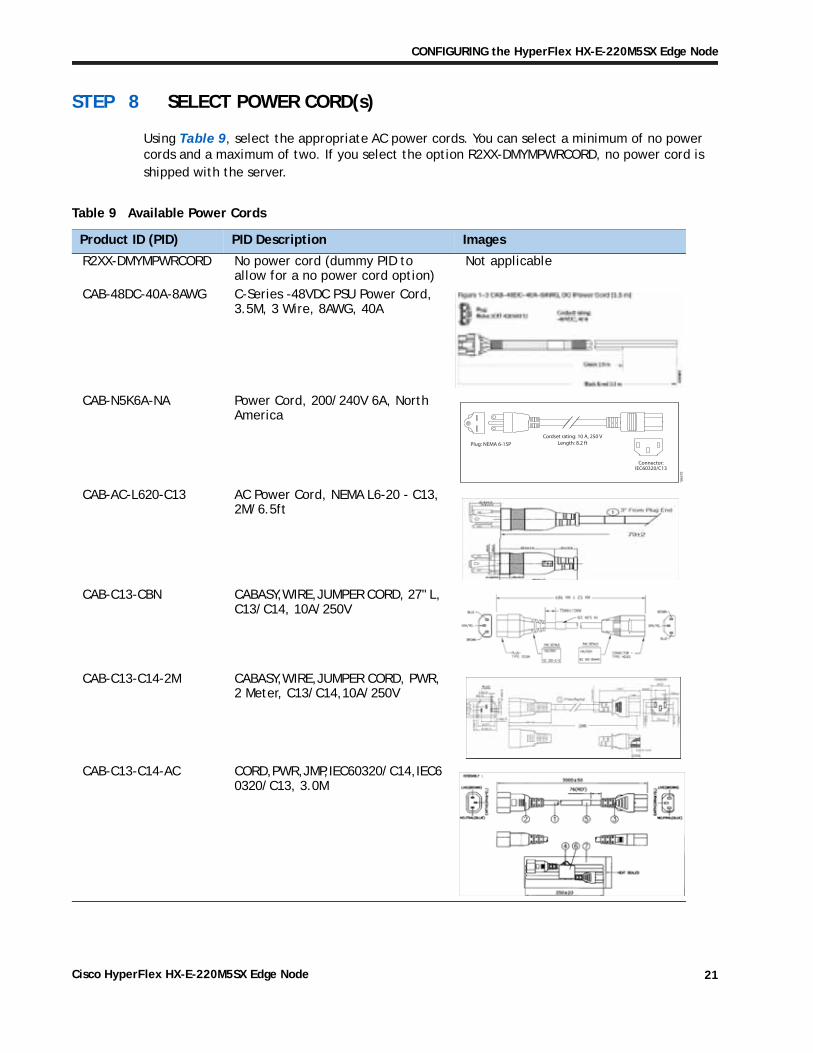
STEP 8 SELECT POWER CORD(s)
Using Table 9, select the appropriate AC power cords. You can select a minimum of no power cords and a maximum of two. If you select the option R2XX-DMYMPWRCORD, no power cord is shipped with the server.
Table 9 Available Power Cords
Product ID (PID) PID Description Images
R2XX-DMYMPWRCORD No power cord (dummy PID to allow for a no power cord option)
Not applicable
CAB-48DC-40A-8AWG C-Series -48VDC PSU Power Cord, 3.5M, 3 Wire, 8AWG, 40A
CAB-N5K6A-NA Power Cord, 200/240V 6A, North America
Cordset rating: 10 A, 250 VLength: 8.2 ft
1865
70
Plug: NEMA 6-15P
Connector:IEC60320/C13
CAB-AC-L620-C13 AC Power Cord, NEMA L6-20 - C13, 2M/6.5ft
CAB-C13-CBN CABASY,WIRE,JUMPER CORD, 27" L, C13/C14, 10A/250V
CAB-C13-C14-2M CABASY,WIRE,JUMPER CORD, PWR, 2 Meter, C13/C14,10A/250V
CAB-C13-C14-AC CORD,PWR,JMP,IEC60320/C14,IEC6 0320/C13, 3.0M
Cisco HyperFlex HX-E-220M5SX Edge Node 21

CONFIGURING the HyperFlex HX-E-220M5SX Edge Node
CAB-250V-10A-AR Power Cord, 250V, 10A, Argentina
1865
71
2500 mm
Cordset rating: 10 A, 250/500 V MAXLength: 8.2 ft
Plug:EL 219
(IRAM 2073) Connector:EL 701
(IEC60320/C13)
CAB-9K10A-AU Power Cord, 250VAC 10A 3112 Plug, Australia
Plug:
Cordset rating: 10 A, 250 V/500 V MAXLength: 2500mm
1865
80
Connector:EL 701C
(EN 60320/C15)EL 210(BS 1363A) 13 AMP fuse
CAB-250V-10A-CN AC Power Cord - 250V, 10A - PRC
CAB-9K10A-EU Power Cord, 250VAC 10A CEE 7/7 Plug, EU
Connector:VSCC15
Cordset rating: 10A/16 A, 250 VLength: 8 ft 2 in. (2.5 m)Plug:
M2511
1865
76
CAB-250V-10A-ID Power Cord, 250V, 10A, India
OVE
Cordset rating 16A, 250V(2500mm)
Plug:EL 208
1874
90
Connector:EL 701
CAB-250V-10A-IS Power Cord, SFS, 250V, 10A, Israel
Cordset rating 10A, 250V/500V MAX(2500 mm)
Plug:EL 212(SI-32)
1865
74
Connector:EL 701B
(IEC60320/C13)
EL-21216A250V
CAB-9K10A-IT Power Cord, 250VAC 10A CEI 23-16/VII Plug, Italy
Plug: I/3G
(CEI 23-16)
Connector C15M
(EN60320/C15 )
Cordset rating: 10 A, 250 VLength: 8 ft 2 in. (2.5 m)
1865
75
CAB-9K10A-SW Power Cord, 250VAC 10A MP232 Plug, Switzerland
Plug:MP232-R
Cordset rating: 10 A, 250 VLength: 8 ft. 2 in (2.5 m)
1865
78
Connector:IEC 60320 C15
Table 9 Available Power Cords
Product ID (PID) PID Description Images
Cisco HyperFlex HX-E-220M5SX Edge Node22

CONFIGURING the HyperFlex HX-E-220M5SX Edge Node
CAB-9K10A-UK Power Cord, 250VAC 10A BS1363 Plug (13 A fuse), UK
Plug:
Cordset rating: 10 A, 250 V/500 V MAXLength: 2500mm
1865
80
Connector:EL 701C
(EN 60320/C15)EL 210(BS 1363A) 13 AMP fuse
CAB-9K12A-NA Power Cord, 125VAC 13A NEMA 5-15 Plug, North America
CAB-250V-10A-BR Power Cord - 250V, 10A - Brazil
CAB-C13-C14-2M-JP Power Cord C13-C14, 2M/6.5ft Japan PSE mark
Image not available
Table 9 Available Power Cords
Product ID (PID) PID Description Images
Connector:IEC60320/C15
Cordset rating 13A, 125V(8.2 feet) (2.5m)
Plug:NEMA 5-15P
1922
60
1 76.2 From Plug End
2,133.6 ± 25
Cisco HyperFlex HX-E-220M5SX Edge Node 23

CONFIGURING the HyperFlex HX-E-220M5SX Edge Node
STEP 9 SELECT ACCESSORIES
Select
(1) Internal microSD Card Module HX-MSD-32G.
• This is a required component.
• The micro-SD card mounts internally on riser 1.
• The micro-SD card serves as a dedicated local resource for utilities such as HUU. Images can be pulled from a file share (NFS/CIFS) and uploaded to the cards for future use.
(2) Optional SFP adapter CVR-QSFP-SFP10G.
• This option may only be selected if operating under RPQ approval.
• Two QSA adapters are mandatory when ordering the VIC1387 MLOM card.
Cisco HyperFlex HX-E-220M5SX Edge Node24
CONFIGURING the HyperFlex HX-E-220M5SX Edge Node
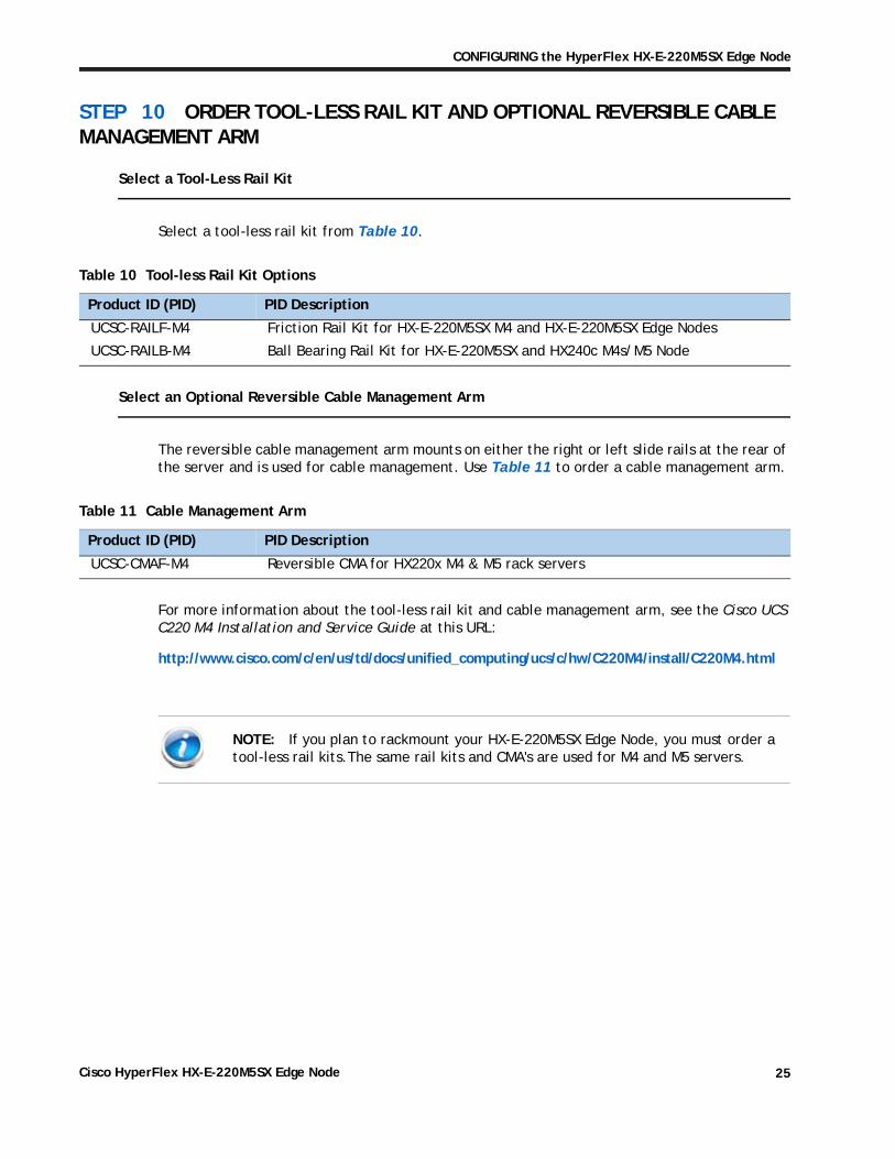
STEP 10 ORDER TOOL-LESS RAIL KIT AND OPTIONAL REVERSIBLE CABLE MANAGEMENT ARM
Select a Tool-Less Rail Kit
Select a tool-less rail kit from Table 10.
Table 10 Tool-less Rail Kit Options
Product ID (PID) PID Description
UCSC-RAILF-M4 Friction Rail Kit for HX-E-220M5SX M4 and HX-E-220M5SX Edge Nodes
UCSC-RAILB-M4 Ball Bearing Rail Kit for HX-E-220M5SX and HX240c M4s/M5 Node
Select an Optional Reversible Cable Management Arm
The reversible cable management arm mounts on either the right or left slide rails at the rear of the server and is used for cable management. Use Table 11 to order a cable management arm.
Table 11 Cable Management Arm
Product ID (PID) PID Description
UCSC-CMAF-M4 Reversible CMA for HX220x M4 & M5 rack servers
For more information about the tool-less rail kit and cable management arm, see the Cisco UCS C220 M4 Installation and Service Guide at this URL:
http://www.cisco.com/c/en/us/td/docs/unified_computing/ucs/c/hw/C220M4/install/C220M4.html
NOTE: If you plan to rackmount your HX-E-220M5SX Edge Node, you must order a tool-less rail kits.The same rail kits and CMA's are used for M4 and M5 servers.
Cisco HyperFlex HX-E-220M5SX Edge Node 25

CONFIGURING the HyperFlex HX-E-220M5SX Edge Node
STEP 11 SELECT OPERATING SYSTEM AND VALUE-ADDED SOFTWARE
Several operating systems and value-added software programs are available. Select as desired from
Table 12 OSs and Value-Added Software
VMware1
HX-VSP-FND-D Factory Installed - vSphere SW (End user to provide License)
HX-VSP-EPL-D Factory Installed - VMware vSphere6 Ent Plus SW+Lic (2CPU)
HX-VSP-ENT-D Factory Installed - VMware vSphere6 Ent SW and Lic (2 CPU)
HX-VSP-STD-D Factory Installed - VMware vSphere6 Ent SW and Lic (2 CPU)
VMWare PAC Licenses2
HX-VSP-EPL-1A VMware vSphere 6 Ent Plus (1 CPU), 1-yr, Support Required Cisco
HX-VSP-EPL-3A VMware vSphere 6 Ent Plus (1 CPU), 3-yr, Support Required Cisco
HX-VSP-EPL-5A VMware vSphere 6 Ent Plus (1 CPU), 5-yr, Support Required Cisco
HX-VSP-STD-1A VMware vSphere 6 Standard (1 CPU), 1-yr, Support Required Cisco
HX-VSP-STD-3A VMware vSphere 6 Standard (1 CPU), 3-yr, Support Required Cisco
HX-VSP-STD-5A VMware vSphere 6 Standard (1 CPU), 5-yr, Support Required Cisco
Software Subscription3
HXDP-E001-1YR= Cisco HyperFlex Data Platform Edge Edition 1 Yr Subscription
HXDP-E001-2YR= Cisco HyperFlex Data Platform Edge Edition 2 Yr Subscription
HXDP-E001-3YR= Cisco HyperFlex Data Platform Edge Edition 3 Yr Subscription
HXDP-E001-4YR= Cisco HyperFlex Data Platform Edge Edition 4 Yr Subscription
HXDP-E001-5YR= Cisco HyperFlex Data Platform Edge Edition 5 Yr Subscription
Table 12
Product ID (PID) PID Description
Notes:
1. Although VMware 6.0 is installed at the factory, VMware 6.5 is also supported. Hyper-V is not supported on HX Edge nodes.
2. Choose quantity of two when choosing PAC licensing for dual CPU systems.3. HyperFlex Edge licensing requires the use of 1-Gb networking, RF2, and enables a fixed 3 node cluster scale.
Cisco HyperFlex HX-E-220M5SX Edge Node26

CONFIGURING the HyperFlex HX-E-220M5SX Edge Node
STEP 12 SELECT SERVICE and SUPPORT LEVEL
A variety of service options are available, as described in this section.
Smart Net Total Care (SNTC) for UCS
For support of the entire Unified Computing System, Cisco offers the Cisco Smart Net Total Care for UCS Service. This service provides expert software and hardware support to help sustain performance and high availability of the unified computing environment. Access to Cisco Technical Assistance Center (TAC) is provided around the clock, from anywhere in the world
For systems that include Unified Computing System Manager, the support service includes downloads of UCSM upgrades. The Cisco Smart Net Total Care for UCS Service includes flexible hardware replacement options, including replacement in as little as two hours. There is also access to Cisco's extensive online technical resources to help maintain optimal efficiency and uptime of the unified computing environment. For more information please refer to the following url: http://www.cisco.com/c/en/us/services/technical/smart-net-total-care.html?stickynav=1
You can choose a desired service listed in Table 13.
Table 13 Cisco SNTC for UCS Service (PID HX-E-220M5SX)
Service SKU Service Level GSP On Site? DescriptionCON-PREM-220CM5SX C2P Yes SNTC 24X7X2OS CON-UCSD8-220CM5SX UCSD8 Yes UC SUPP DR 24X7X2OS*CON-C2PL-220CM5SX C2PL Yes LL 24X7X2OS**CON-OSP-220CM5SX C4P Yes SNTC 24X7X4OS CON-UCSD7-220CM5SX UCSD7 Yes UCS DR 24X7X4OS*CON-C4PL-220CM5SX C4PL Yes LL 24X7X4OS**CON-USD7L-220CM5SX USD7L Yes LLUCS HW DR 24X7X4OS***CON-OSE-220CM5SX C4S Yes SNTC 8X5X4OS CON-UCSD6-220CM5SX UCSD6 Yes UC SUPP DR 8X5X4OS*CON-SNCO-220CM5SX SNCO Yes SNTC 8x7xNCDOS****CON-OS-220CM5SX CS Yes SNTC 8X5XNBDOS CON-UCSD5-220CM5SX UCSD5 Yes UCS DR 8X5XNBDOS*CON-S2P-220CM5SX S2P No SNTC 24X7X2 CON-S2PL-220CM5SX S2PL No LL 24X7X2**CON-SNTP-220CM5SX SNTP No SNTC 24X7X4 CON-SNTPL-220CM5SX SNTPL No LL 24X7X4**CON-SNTE-220CM5SX SNTE No SNTC 8X5X4 CON-SNC-220CM5SX SNC No SNTC 8x7xNCD****CON-SNT-220CM5SX SNT No SNTC 8X5XNBDCON-SW-220CM5SX SW No SNTC NO RMA*Includes Drive Retention (see below for full description)**Includes Local Language Support (see below for full description) – Only available in China and Japan***Includes Local Language Support and Drive Retention – Only available in China and Japan****Available in China Only
Cisco HyperFlex HX-E-220M5SX Edge Node 27

CONFIGURING the HyperFlex HX-E-220M5SX Edge Node
Smart Net Total Care with Onsite Troubleshooting Service
An enhanced offer over traditional Smart Net Total Care which provides onsite troubleshooting expertise to aid in the diagnostics and isolation of hardware issue within our customers’ Cisco Hyper-Converged environment. It is delivered by a Cisco Certified field engineer (FE) in collaboration with remote TAC engineer and Virtual Internet working Support Engineer (VISE). You can choose a desired service listed in
Table 14 SNTC with UCS Onsite Troubleshooting Service (PID HX-E-220M5SX)
Service SKU Service Level GSP On Site? Description
CON-OSPT-220CM5SX OSPT Yes 24X7X4OS Trblshtg
CON-OSPTD-220CM5SX OSPTD Yes 24X7X4OS TrblshtgDR*
CON-OSPTL-220CM5SX OSPTL Yes 24X7X4OS TrblshtgLL**
CON-OPTLD-220CM5SX OPTLD Yes 24X7X4OS TrblshtgLLD***
*Includes Drive Retention (see below for full description)
**Includes Local Language Support (see below for full description) – Only available in China and Japan
***Includes Local Language Support and Drive Retention – Only available in China and Japan
Table 14
Solution Support
Solution Support includes both Cisco product support and solution-level support, resolving complex issues in multivendor environments, on average, 43% more quickly than product support alone. Solution Support is a critical element in data center administration, to help rapidly resolve any issue encountered, while maintaining performance, reliability, and return on investment.
This service centralizes support across your multivendor Cisco environment for both our products and solution partner products you've deployed in your ecosystem. Whether there is an issue with a Cisco or solution partner product, just call us. Our experts are the primary point of contact and own the case from first call to resolution. For more information please refer to the following url:http://www.cisco.com/c/en/us/services/technical/solution-support.html?stickynav=1You can choose a desired service listed in Table 15
Table 15 Solution Support Service (PID HX-E-220M5SX)
Service SKU Service Level GSP On Site? Description
CON-SSC2P-220CM5SX SSC2P Yes SOLN SUPP 24X7X2OS
CON-SSC4P-220CM5SX SSC4P Yes SOLN SUPP 24X7X4OS
CON-SSC4S-220CM5SX SSC4S Yes SOLN SUPP 8X5X4OS
CON-SSCS-220CM5SX SSCS Yes SOLN SUPP 8X5XNBDOS
Cisco HyperFlex HX-E-220M5SX Edge Node28

CONFIGURING the HyperFlex HX-E-220M5SX Edge Node
Partner Support Service for UCS
Cisco Partner Support Service (PSS) is a Cisco Collaborative Services service offering that is designed for partners to deliver their own branded support and managed services to enterprise customers. Cisco PSS provides partners with access to Cisco's support infrastructure and assets to help them:
Expand their service portfolios to support the most complex network environments
Lower delivery costs
Deliver services that increase customer loyalty
PSS options enable eligible Cisco partners to develop and consistently deliver high-value technical support that capitalizes on Cisco intellectual assets. This helps partners to realize higher margins and expand their practice.
PSS is available to all Cisco PSS partners.
PSS provides hardware and software support, including triage support for third party software, backed by Cisco technical resources and level three support. You can choose a desired service listed in Table 16.
CON-SSDR7-220CM5SX SSDR7 Yes SSPT DR 24X7X4OS*
CON-SSDR5-220CM5SX SSDR5 Yes SSPT DR 8X5XNBDOS*
CON-SSS2P-220CM5SX SSS2P No SOLN SUPP 24X7X2
CON-SSSNP-220CM5SX SSSNP No SOLN SUPP 24X7X4
CON-SSSNE-220CM5SX SSSNE No SOLN SUPP 8X5X4
CON-SSSNC-220CM5SX SSSNC No SOLN SUPP NCD**
CON-SSSNT-220CM5SX SSSNT No SOLN SUPP 8X5XNBD
Includes Drive Retention (see below for description)
**Available in China only
Table 16 PSS (PID HX-E-220M5SX)
Service SKU Service Level GSP On Site? Description
CON-PSJ8-220CM5SX PSJ8 Yes UCS PSS 24X7X2 OSCON-PSJ7-220CM5SX PSJ7 Yes UCS PSS 24X7X4 OSCON-PSJD7-220CM5SX PSJD7 Yes UCS PSS 24X7X4 DR*CON-PSJ6-220CM5SX PSJ6 Yes UCS PSS 8X5X4 OSCON-PSJD6-220CM5SX PSJD6 Yes UCS PSS 8X5X4 DR*CON-PSJ4-220CM5SX PSJ4 No UCS SUPP PSS 24X7X2 CON-PSJ3-220CM5SX PSJ3 No UCS SUPP PSS 24X7X4 CON-PSJ2-220CM5SX PSJ2 No UCS SUPP PSS 8X5X4
Table 15 Solution Support Service (PID HX-E-220M5SX)
Cisco HyperFlex HX-E-220M5SX Edge Node 29

CONFIGURING the HyperFlex HX-E-220M5SX Edge Node
Combined Support Service
Combined Services makes it easier to purchase and manage required services under one contract. The more benefits you realize from the Cisco HyperFlex System, the more important the technology becomes to your business. These services allow you to:
Optimize the uptime, performance, and efficiency of your HyperFlex System
Protect your vital business applications by rapidly identifying and addressing issues
Strengthen in-house expertise through knowledge transfer and mentoring
Improve operational efficiency by allowing HyperFlex experts to augment your internal staff resources
Enhance business agility by diagnosing potential issues before they affect your operations
You can choose a desired service listed in
Table 17 Combined Support Service (PID HX-E-220M5SX)
Service SKU Service Level GSP On Site? Description
CON-NCF2P-220CM5SX NCF2P Yes CMB SVC 24X7X2OSCON-NCF4P-220CM5SX NCF4P Yes CMB SVC 24X7X4OSCON-NCF4S-220CM5SX NCF4S Yes CMB SVC 8X5X4OSCON-NCFCS-220CM5SX NCFCS Yes CMB SVC 8X5XNBDOSCON-NCF2-220CM5SX NCF2 No CMB SVC 24X7X2CON-NCFP-220CM5SX NCFP No CMB SVC 24X7X4CON-NCFE-220CM5SX NCFE No CMB SVC 8X5X4CON-NCFT-220CM5SX NCFT No CMB SVC 8X5XNBDCON-NCFW-220CM5SX NCFW No CMB SVC SW
Table 17
UCS Drive Retention Service
With the Cisco Drive Retention Service, you can obtain a new disk drive in exchange for a faulty drive without returning the faulty drive.
Sophisticated data recovery techniques have made classified, proprietary, and confidential information vulnerable, even on malfunctioning disk drives. The Drive Retention service enables you to retain your drives and ensures that the sensitive data on those drives is not compromised, which reduces the risk of any potential liabilities. This service also enables you to comply with regulatory, local, and federal requirements.
CON-PSJ1-220CM5SX PSJ1 No UCS SUPP PSS 8X5XNBD *Includes Drive Retention (see below for description)
Table 16 PSS (PID HX-E-220M5SX)
Cisco HyperFlex HX-E-220M5SX Edge Node30

CONFIGURING the HyperFlex HX-E-220M5SX Edge Node
If your company has a need to control confidential, classified, sensitive, or proprietary data, you might want to consider one of the Drive Retention Services listed in the above tables (where available)
NOTE: Cisco does not offer a certified drive destruction service as part of this service.
Local Language Technical Support for UCS
Where available, and subject to an additional fee, local language support for calls on all assigned severity levels may be available for specific product(s) – see tables above.
For a complete listing of available services for Cisco HyperFlex System, see the following URL: https://www.cisco.com/c/en/us/services/technical.html?stickynav=1
Cisco HyperFlex HX-E-220M5SX Edge Node 31

OPTIONAL STEP - ORDER RACK(s)
OPTIONAL STEP - ORDER RACK(s)The optional R42612 rack is available from Cisco for the C-Series servers, including the HX-E-220M5SX Edge Node. This rack is a standard 19-inch rack and can be ordered with a variety of options, as listed in Table 18. Racks are shipped separately from the HX-E-220M5SX Edge Node.
Table 18 Racks and Rack Options
Product ID (PID) PID Description
RACK2-UCS Cisco R42612 expansion rack, no side panels. This type of rack is used for multiple-rack deployments.
RACK2-UCS2 Cisco R42612 static (standard) rack, with side panels. This type of rack is used for single-rack and end of row deployments. Side panels are needed for racks at the ends of multiple-rack deployments. For example, when configuring a row of 5 racks, order 1 standard rack plus 4 expansion racks. Apply the side panels from the standard rack to the racks at each end of the row.
RACK-BLANK-001 Blanking panels (qty 12), 1U, plastic, toolless.Recommended to ensure proper airflow. Fill all empty RU spaces in the front of the rack. Because each blanking panel PID includes 12 panels, use the following calculation: 42RU - occupied RU = available RU. Divide available RU by 12 to determine PID order quantity.
RACK-CBLMGT-001 Cable mgt D rings (qty 10), metal.Use the D rings to bundle system cables to ensure proper airflow.
RACK-CBLMGT-003 Brush strip (qty 1), 1 U.The brush strip promotes proper airflow while allowing cables to be passed from the front to the rear of the rack.
RACK-CBLMGT-011 Cable mgt straps (qty 10), Velcro.Use the Velcro straps to bundle system cables to ensure proper airflow.
RACK-FASTEN-001 Mounting screws (qty 100), M6.The rack ships with nuts and screws, but extras may be ordered.
RACK-FASTEN-002 Cage nuts (qty 50), M6.The rack ships with nuts and screws, but extras may be ordered.
RACK2-JOIN-001 Rack joining kit.Use the kit to connect adjacent racks within a row. Order 1 unit less than the number of racks in the row.
RACK2-GRND-001 Cisco R42612 grounding kit
Cisco HyperFlex HX-E-220M5SX Edge Node32

OPTIONAL STEP - ORDER PDU
OPTIONAL STEP - ORDER PDUAn optional power distribution unit (PDU) is available from Cisco for the C-Series rack servers. This PDU is available in a zero rack unit (RU) style or horizontal PDU style see Cisco RP-Series Rack and Rack PDU specification for more details at
http://www.cisco.com/c/dam/en/us/products/collateral/servers-unified-computing/r-series-racks/rack-pdu-specsheet.pdf
Cisco HyperFlex HX-E-220M5SX Edge Node 33

SUPPLEMENTAL MATERIAL
SUPPLEMENTAL MATERIAL
Supported Network Topologies for HyperFlex Edge Deployments
There are two virtual networking topologies supported with HyperFlex Edge, single 1GbE switch configuration and dual 1GbE switch configuration. Customers have the flexibility to choose the design that meets their individual needs. Below is a summary of the supported topologies, refer to the Cisco HyperFlex Edge Deployment Guide, Pre-installation Checklist chapter, for more detail. (CCO login required)
https://www.cisco.com/c/en/us/td/docs/hyperconverged_systems/HyperFlex_HX_DataPlatformSoftware/Edge_Deployment_Guide/b_HyperFlex_Edge_Deployment_Guide_2_6/b_Cisco_HyperFlex_ROBO_Installation_Guide_chapter_011.html
Single Switch Configuration
Single switch configuration provides a simple topology requiring only a single switch, and two 1GbE ports per server. Link or switch redundancy is not provided. Access ports and trunk ports are the two supported network port configurations.
Figure 5 Network Topology
HyperFlex Edge Cluster
Edge Node 1 Edge Node 2
30
62
46
UCS Hardware
VMVMVM CTL VM
Edge Node 3
Hypervisor
UCS Hardware
VMVMVM CTL VM
Hypervisor
P1 1GB LOM P2 1GB LOM
ToR Switch – N9/7/5K/Catalyst/Other
hx-storage-datahx-inband-mgmt
vmnic1/Port #2vmnic0/Port #1
VM VM VM CTL VM
Hypervisor
UCS Hardware
vmk0 vmk1
CIMC
Mgmt, VM guest, vMotion Traffic Storage Data Traffic
Network
Cisco HyperFlex HX-E-220M5SX Edge Node34
SUPPLEMENTAL MATERIAL
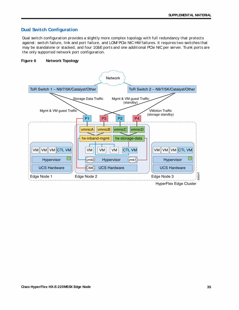
Dual Switch Configuration
Dual switch configuration provides a slightly more complex topology with full redundancy that protects against: switch failure, link and port failure, and LOM/PCIe NIC HW failures. It requires two switches that may be standalone or stacked, and four 1GbE ports and one additional PCIe NIC per server. Trunk ports are the only supported network port configuration.
Figure 6 Network Topology
Mgmt & VM guest Traffic
Storage Data Traffic
HyperFlex Edge Cluster
Edge Node 1 Edge Node 2
3062
47
UCS Hardware
VMVMVM CTL VM
Edge Node 3
Hypervisor
UCS Hardware
VMVMVM CTL VM
Hypervisor
P3
ToR Switch 1 – N9/7/5K/Catalyst/Other ToR Switch 2 – N9/7/5K/Catalyst/Other
hx-storage-data
vmnicC vmnicD
VM VM VM CTL VM
Hypervisor
UCS Hardware
vmk0 vmk1
CIMC
VMotion Traffic(storage standby)
Mgmt & VM guest Traffic(standby)
Network
P1 P4P2
hx-inband-mgmt
vmnicA vmnicB
Cisco HyperFlex HX-E-220M5SX Edge Node 35

SUPPLEMENTAL MATERIAL
CHASSIS
An internal view of the HX-E-220M5SX Edge Node chassis with the top cover removed is shown in Figure 7.
Figure 7 HX-E-220M5SX Edge With Top Cover Off
1 Drive bays 1–10 are hot swappable 9 Power supplies (Hot-swappable when redundant as 1+1)
2 Cooling fan modules (seven) 10 Trusted platform module (TPM) socket on motherboard (not visible in this view)
3 N/A 11 PCIe slot 2 (half-height, x16)
4 DIMM sockets on motherboard (up to 12 per CPU; total 24)
12 PCIe slot 1 (full-height, x16); includes socket for Micro-SD card
5 CPUs and heatsinks (up to two) 13 Modular LOM (mLOM) card bay on chassis floor (x16) (not visible in this view)
6 Mini storage module connector
For M.2 module with SATA M.2 SSD slots
14 Cisco 12 Gbps Modular SAS HBA controller card
7 Internal USB 3.0 port on motherboard 15 Micro-SD card socket on PCIe riser 1
8 RTC battery vertical socket on motherboard - -
Fan 07
Fan 06
Fan 05
Fan 03
CPU 01
CPU 02
PSU 02
PSU 01
PCIe 02
PCIe 01
SCPM
Fan 02
Fan 01
Fan 04 10
11
12
3059
52
2 4
14
5 6 7 83
9
1
mRAID 13
15
Cisco HyperFlex HX-E-220M5SX Edge Node36

SUPPLEMENTAL MATERIAL
Block Diagram
Figure 8 HX-E-220M5SX Edge Block Diagram
Cisco HyperFlex HX-E-220M5SX Edge Node 37

SUPPLEMENTAL MATERIAL
Serial Port Details
The pinout details of the rear RJ-45 serial port connector are shown in Figure 9.
Figure 9 Serial Port (Female RJ-45 Connector) Pinout
1 2345678
Pin
Serial Port (RJ-45 Female Connector)
Signal
RTS (Request to Send)DTR (Data Terminal Ready)TxD (Transmit Data)
RxD (Receive Data)DSR (Data Set Ready)CTS (Clear to Send)
GND (Signal Ground)GND (Signal Ground)
Cisco HyperFlex HX-E-220M5SX Edge Node38

SUPPLEMENTAL MATERIAL
Upgrade and Servicing-Related Parts
This section lists the upgrade and servicing-related parts you may need during the life of your system. Some of these parts are configured with every system, and some may be ordered when needed or may be ordered and kept on hand as spares for future use.
Table 19 Upgrade and Servicing-related Parts for UCS HX-E-220M5SX Edge Server
Spare Product ID (PID) Description
UCSC-HS-C220M5= Heat sink for UCS C220 M5 rack servers 150W CPUs & below
UCSC-HS2-C220M5= Heat sink for UCS C220 M5 rack servers CPUs above 150W
UCS-CPUAT= CPU Assembly Tool for M5 Servers
UCS-CPU-TIM= CPU thermal interface material syringe for M5 server HS seal
UCSX-HSCK= UCS Processor Heat Sink Cleaning Kit For Replacement of CPU
UCS-M5-CPU-CAR= UCS M5 CPU Carrier
CBL-NVME-C220FF= C220 M5L/M5S PCIe SSD cable (1) for SFF & LFF chassis
UCSC-SATA-KIT-M5= C220 M5 (2) SATA/SW RAID cables, 1U riser & interposer, for up to 8-drives
UCSC-SATAIN-220M5= C220 M5 (8-drive) SATA Interposer board
CBL-SC-MR12GM5= Super Cap cable for UCSC-RAID-M5 for C220 M5 Servers
UCSC-XRAIDR-220M5= Riser to support SATA, MRAID for C220 M5 servers
UCSC-BBLKD-S2= C-Series M5 SFF drive blanking panel
UCSC-PCIF-01H= PCIe Low Profile blanking panel for UCS C-Series Server
UCSC-PCIF-01F= PCIe Full Height blanking panel for UCS C-Series Server
UCSC-MLOM-BLK= MLOM Blanking Panel
UCSC-RAILF-M4= Friction Rail Kit for C220 M4 rack servers
UCSC-CMAF-M4= Reversible CMA for C220 M4 friction & ball bearing rail kits
UCSC-RAILB-M4= Ball Bearing Rail Kit for C220 M4 and C240 M4 rack servers
UCSC-BZL-C220M5= C220 M5 Security Bezel
UCSC-FAN-C220M5= C220 M5 Fan Module (one)
N20-BKVM= KVM cable for Server console port
UCSC-PSU-BLKP1U= Power Supply Blanking Panel for C220 M5 and C240 M5 servers
UCS-MSTOR-SD= Mini Storage Carrier for SD (holds up to 2)
UCS-MSTOR-M2= Mini Storage Carrier for M.2 SATA/NVME (holds up to 2)
Cisco HyperFlex HX-E-220M5SX Edge Node 39
SUPPLEMENTAL MATERIAL
RACKS
The Cisco R42612 rack is certified for Cisco UCS installation at customer sites and is suitable for the following equipment:
Cisco UCS B-Series servers and fabric interconnects
Cisco UCS C-Series and select Nexus switches
The rack is compatible with hardware designed for EIA-standard 19-inch racks.Cisco R42612 Rack. See Cisco RP-Series Rack and Rack PDU specification for more details at
http://www.cisco.com/c/dam/en/us/products/collateral/servers-unified-computing/r-series-racks/rack-pdu-specsheet.pdf
Cisco HyperFlex HX-E-220M5SX Edge Node40

SUPPLEMENTAL MATERIAL
PDUs
Cisco RP Series Power Distribution Units (PDUs) offer power distribution with branch circuit protection.
Cisco RP Series PDU models distribute power to up to 42 outlets. The architecture organizes power distribution, simplifies cable management, and enables you to move, add, and change rack equipment without an electrician.
With a Cisco RP Series PDU in the rack, you can replace up to two dozen input power cords with just one. The fixed input cord connects to the power source from overhead or under-floor distribution. Your IT equipment is then powered by PDU outlets in the rack using short, easy-to-manage power cords.
The C-series severs accept the zero-rack-unit (0RU) or horizontal PDU. See Cisco RP-Series Rack and Rack PDU specification for more details at
http://www.cisco.com/c/dam/en/us/products/collateral/servers-unified-computing/r-series-racks/rack-pdu-specsheet.pdf
Cisco HyperFlex HX-E-220M5SX Edge Node 41
SUPPLEMENTAL MATERIAL
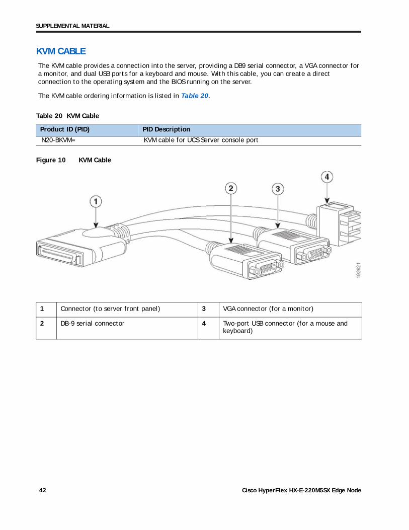
KVM CABLE
The KVM cable provides a connection into the server, providing a DB9 serial connector, a VGA connector for a monitor, and dual USB ports for a keyboard and mouse. With this cable, you can create a direct connection to the operating system and the BIOS running on the server.
The KVM cable ordering information is listed in Table 20.
Table 20 KVM Cable
Product ID (PID) PID Description
N20-BKVM= KVM cable for UCS Server console port
Figure 10 KVM Cable
1 Connector (to server front panel) 3 VGA connector (for a monitor)
2 DB-9 serial connector 4 Two-port USB connector (for a mouse and keyboard)
Cisco HyperFlex HX-E-220M5SX Edge Node42

TECHNICAL SPECIFICATIONS
TECHNICAL SPECIFICATIONS
Dimensions and Weight
Table 21 UCS HX-E-220M5SX Edge Dimensions and Weight
Parameter Value
Height 1.7 in. (4.32 cm)Width 16.89 in. (43.0 cm)
including handles:
18.98 in. (48.2 cm)Depth 29.8 in. (75.6 cm)
including handles:
30.98 in. (78.7 cm)Front Clearance 3 in. (76 mm)Side Clearance 1 in. (25 mm)Rear Clearance 6 in. (152 mm)WeightMaximum (8 HDDs, 2 CPUs, 16 DIMMs, two power supplies) 37.5 lbs (17.0 kg)Minimum (1 HDD, 1 CPU, 1 DIMM, one power supply) 29.0 lbs (13.2 kg)Bare (0 HDD, 0 CPU, 0 DIMM, one power supply) 26.7 lbs (12.1 kg)
Cisco HyperFlex HX-E-220M5SX Edge Node 43

TECHNICAL SPECIFICATIONS
Power Specifications
The server is available with the following types of power supplies:
770 W (AC) power supply (see Table 22).
1050 W (AC) power supply (see Table 23).
1050 W V2 (DC) power supply (see Table 24)
Table 22 UCS HX-E-220M5SX Edge Power Specifications (770 W AC power supply)
Parameter Specification
Input Connector IEC320 C14
Input Voltage Range (V rms) 100 to 240
Maximum Allowable Input Voltage Range (V rms) 90 to 264
Frequency Range (Hz) 50 to 60
Maximum Allowable Frequency Range (Hz) 47 to 63
Maximum Rated Output (W) 770
Maximum Rated Standby Output (W) 36
Nominal Input Voltage (V rms) 100 120 208 230
Nominal Input Current (A rms) 8.8 7.4 4.2 3.8
Maximum Input at Nominal Input Voltage (W) 855 855 855 846
Maximum Input at Nominal Input Voltage (VA) 882 882 882 872
Minimum Rated Efficiency (%)1 90 90 90 91
Minimum Rated Power Factor1 0.97 0.97 0.97 0.97
Maximum Inrush Current (A peak) 15
Maximum Inrush Current (ms) 0.2
Minimum Ride-Through Time (ms)2 12
Notes:
1. This is the minimum rating required to achieve 80 PLUS Platinum certification, see test reports published at http://www.80plus.org/ for certified values
2. Time output voltage remains within regulation limits at 100% load, during input voltage dropout
Table 23 UCS HX-E-220M5SX Edge 1050 W (AC) Power Supply Specifications
Parameter Specification
Input Connector IEC320 C14
Input Voltage Range (V rms) 100 to 240
Maximum Allowable Input Voltage Range (V rms) 90 to 264
Frequency Range (Hz) 50 to 60
Maximum Allowable Frequency Range (Hz) 47 to 63
Cisco HyperFlex HX-E-220M5SX Edge Node44

TECHNICAL SPECIFICATIONS
Maximum Rated Output (W)1 800 1050
Maximum Rated Standby Output (W) 36
Nominal Input Voltage (V rms) 100 120 208 230
Nominal Input Current (A rms) 9.2 7.6 5.8 5.2
Maximum Input at Nominal Input Voltage (W) 889 889 1167 1154
Maximum Input at Nominal Input Voltage (VA) 916 916 1203 1190
Minimum Rated Efficiency (%)2 90 90 90 91
Minimum Rated Power Factor2 0.97 0.97 0.97 0.97
Maximum Inrush Current (A peak) 15
Maximum Inrush Current (ms) 0.2
Minimum Ride-Through Time (ms)3 12
Notes:
1. Maximum rated output is limited to 800W when operating at low-line input voltage (100-127V)2. This is the minimum rating required to achieve 80 PLUS Platinum certification, see test reports published at
http://www.80plus.org/ for certified values3. Time output voltage remains within regulation limits at 100% load, during input voltage dropout
Table 24 UCS HX-E-220M5SX Edge 1050 W (DC) Power Supply Specifications
Parameter Specification
Input Connector Molex 42820
Input Voltage Range (V rms) -48
Maximum Allowable Input Voltage Range (V rms) -40 to -72
Frequency Range (Hz) NA
Maximum Allowable Frequency Range (Hz) NA
Maximum Rated Output (W) 1050
Maximum Rated Standby Output (W) 36
Nominal Input Voltage (V rms) -48
Nominal Input Current (A rms) 24
Maximum Input at Nominal Input Voltage (W) 1154
Maximum Input at Nominal Input Voltage (VA) 1154
Minimum Rated Efficiency (%)1 91
Minimum Rated Power Factor1 NA
Maximum Inrush Current (A peak) 15
Maximum Inrush Current (ms) 0.2
Minimum Ride-Through Time (ms)2 5
Table 23 UCS HX-E-220M5SX Edge 1050 W (AC) Power Supply Specifications
Cisco HyperFlex HX-E-220M5SX Edge Node 45

TECHNICAL SPECIFICATIONS
For configuration-specific power specifications, use the Cisco UCS Power Calculator at this URL:
http://ucspowercalc.cisco.com
Notes:
1. This is the minimum rating required to achieve 80 PLUS Platinum certification, see test reports published at http://www.80plus.org/ for certified values
2. Time output voltage remains within regulation limits at 100% load, during input voltage dropout
Cisco HyperFlex HX-E-220M5SX Edge Node46

TECHNICAL SPECIFICATIONS
Environmental Specifications
The environmental specifications for the HX-E-220M5SX Edge server are listed in Table 25.
Table 25 HX-E-220M5SX Edge Environmental Specifications
Parameter Minimum
Operating Temperature 10oC to 35oC (50oF to 95oF) with no direct sunlight
Maximum allowable operating temperature de-rated
1oC/300 m (1oF/547 ft) above 950 m (3117 ft)
Extended Operating Temperature 5oC to 40oC (41oF to 104oF) with no direct sunlight
Maximum allowable operating temperature de-rated
1oC/175 m (1oF/319 ft) above 950 m (3117 ft)
5oC to 45oC (41oF to 113oF) with no direct sunlight
Maximum allowable operating temperature de-rated
1oC/125 m (1oF/228 ft) above 950 m (3117 ft)
System performance may be impacted when operating in the
extended operating temperature range.
Operation above 40C is limited to less than 1% of annual
operating hours.
Hardware configuration limits apply to extended
operating temperature range.
Non-Operating Temperature -40oC to 65oC (-40oF to 149oF)
Maximum rate of change (operating and non-operating)
20oC/hr (36oF/hr)
Operating Relative Humidity 8% to 90% and 24oC (75oF) maximum dew-point temperature,
non-condensing environment
Non-Operating Relative Humidity 5% to 95% and 33oC (91oF) maximum dew-point temperature,
non-condensing environment
Operating Altitude 0 m to 3050 m {10,000 ft)Sound Power level, Measure A-weighted per ISO7779 LWAd (Bels) Operation at 73°F (23°C)
5.8
Sound Pressure level, Measure A-weighted per ISO7779 LpAm (dBA) Operation at 73°F (23°C)
43
Cisco HyperFlex HX-E-220M5SX Edge Node 47

TECHNICAL SPECIFICATIONS
Table 26 Cisco HX-E-220M5SX Edge Extended Operating Temperature Hardware Configuration Limits
Platform1
Processors: 155W+ 155W+ and 105W+ (4 or 6 Cores)Memory: LRDIMMs LRDIMMsStorage: M.2 SATA SSDs
NVMe SSDs
M.2 SATA SSDs
NVMe SSDsPeripherals: PCIe NVMe SSDs
GPUs
MRAID
PCIe NVMe SSDs
GPUs
mLOMs
VICs
NICs
HBAs
Extended Operating Temperature Hardware Configuration Limits
Notes:
1. Two PSUs are required and PSU failure is not supported
ASHRAE A3 (5oC to 40oC)2
2. Non-Cisco UCS qualified peripherals and/or peripherals that consume more than 25W are not supported
ASHRAE A4 (5oC to 45oC)3
3. High power or maximum power fan control policy must be applied
Cisco HyperFlex HX-E-220M5SX Edge Node48

TECHNICAL SPECIFICATIONS
Compliance Requirements
The regulatory compliance requirements for C-Series servers are listed in Table 27.
Table 27 UCS C-Series Regulatory Compliance Requirements
Parameter Description
Regulatory Compliance Products should comply with CE Markings per directives 2014/30/EU and 2014/35/EU
Safety UL 60950-1 Second EditionCAN/CSA-C22.2 No. 60950-1 Second EditionEN 60950-1 Second EditionIEC 60950-1 Second EditionAS/NZS 60950-1GB4943 2001
EMC - Emissions 47CFR Part 15 (CFR 47) Class A AS/NZS CISPR32 Class A CISPR32 Class AEN55032 Class A ICES003 Class A VCCI Class A EN61000-3-2EN61000-3-3KN32 Class A CNS13438 Class A
EMC - Immunity EN55024CISPR24EN300386KN35
Cisco HyperFlex HX-E-220M5SX Edge Node 49

TECHNICAL SPECIFICATIONS
Cisco HyperFlex HX-E-220M5SX Edge Node50