Cisco HX240c M4 Hyperflex Node Installation Guidecontent.etilize.com/User-Manual/1033227766.pdfiii...
130
Cisco Systems, Inc. www.cisco.com Cisco has more than 200 offices worldwide. Addresses, phone numbers, and fax numbers are listed on the Cisco website at www.cisco.com/go/offices. Cisco HX240c M4 Hyperflex Node Installation Guide May 13, 2016 Text Part Number:
Transcript of Cisco HX240c M4 Hyperflex Node Installation Guidecontent.etilize.com/User-Manual/1033227766.pdfiii...
Cisco HX240c M4 Hyperflex Node Installation GuideMay 13, 2016
Cisco Systems, Inc.www.cisco.com
Cisco has more than 200 offices worldwide. Addresses, phone numbers, and fax numbers are listed on the Cisco website at www.cisco.com/go/offices.
Text Part Number:

THE SPECIFICATIONS AND INFORMATION REGARDING THE PRODUCTS IN THIS MANUAL ARE SUBJECT TO CHANGE WITHOUT NOTICE. ALL STATEMENTS, INFORMATION, AND RECOMMENDATIONS IN THIS MANUAL ARE BELIEVED TO BE ACCURATE BUT ARE PRESENTED WITHOUT WARRANTY OF ANY KIND, EXPRESS OR IMPLIED. USERS MUST TAKE FULL RESPONSIBILITY FOR THEIR APPLICATION OF ANY PRODUCTS.
THE SOFTWARE LICENSE AND LIMITED WARRANTY FOR THE ACCOMPANYING PRODUCT ARE SET FORTH IN THE INFORMATION PACKET THAT SHIPPED WITH THE PRODUCT AND ARE INCORPORATED HEREIN BY THIS REFERENCE. IF YOU ARE UNABLE TO LOCATE THE SOFTWARE LICENSE OR LIMITED WARRANTY, CONTACT YOUR CISCO REPRESENTATIVE FOR A COPY.
The following information is for FCC compliance of Class A devices: This equipment has been tested and found to comply with the limits for a Class A digital device, pursuant to part 15 of the FCC rules. These limits are designed to provide reasonable protection against harmful interference when the equipment is operated in a commercial environment. This equipment generates, uses, and can radiate radio-frequency energy and, if not installed and used in accordance with the instruction manual, may cause harmful interference to radio communications. Operation of this equipment in a residential area is likely to cause harmful interference, in which case users will be required to correct the interference at their own expense.
The following information is for FCC compliance of Class B devices: This equipment has been tested and found to comply with the limits for a Class B digital device, pursuant to part 15 of the FCC rules. These limits are designed to provide reasonable protection against harmful interference in a residential installation. This equipment generates, uses and can radiate radio frequency energy and, if not installed and used in accordance with the instructions, may cause harmful interference to radio communications. However, there is no guarantee that interference will not occur in a particular installation. If the equipment causes interference to radio or television reception, which can be determined by turning the equipment off and on, users are encouraged to try to correct the interference by using one or more of the following measures:
• Reorient or relocate the receiving antenna.
• Increase the separation between the equipment and receiver.
• Connect the equipment into an outlet on a circuit different from that to which the receiver is connected.
• Consult the dealer or an experienced radio/TV technician for help.
Modifications to this product not authorized by Cisco could void the FCC approval and negate your authority to operate the product.
The Cisco implementation of TCP header compression is an adaptation of a program developed by the University of California, Berkeley (UCB) as part of UCB’s public domain version of the UNIX operating system. All rights reserved. Copyright © 1981, Regents of the University of California.
NOTWITHSTANDING ANY OTHER WARRANTY HEREIN, ALL DOCUMENT FILES AND SOFTWARE OF THESE SUPPLIERS ARE PROVIDED “AS IS” WITH ALL FAULTS. CISCO AND THE ABOVE-NAMED SUPPLIERS DISCLAIM ALL WARRANTIES, EXPRESSED OR IMPLIED, INCLUDING, WITHOUT LIMITATION, THOSE OF MERCHANTABILITY, FITNESS FOR A PARTICULAR PURPOSE AND NONINFRINGEMENT OR ARISING FROM A COURSE OF DEALING, USAGE, OR TRADE PRACTICE.
IN NO EVENT SHALL CISCO OR ITS SUPPLIERS BE LIABLE FOR ANY INDIRECT, SPECIAL, CONSEQUENTIAL, OR INCIDENTAL DAMAGES, INCLUDING, WITHOUT LIMITATION, LOST PROFITS OR LOSS OR DAMAGE TO DATA ARISING OUT OF THE USE OR INABILITY TO USE THIS MANUAL, EVEN IF CISCO OR ITS SUPPLIERS HAVE BEEN ADVISED OF THE POSSIBILITY OF SUCH DAMAGES.
CCDE, CCENT, CCSI, Cisco Eos, Cisco Explorer, Cisco HealthPresence, Cisco IronPort, the Cisco logo, Cisco Nurse Connect, Cisco Pulse, Cisco SensorBase,Cisco StackPower, Cisco StadiumVision, Cisco TelePresence, Cisco TrustSec, Cisco Unified Computing System, Cisco WebEx, DCE, Flip Channels, Flip for Good, FlipMino, Flipshare (Design), Flip Ultra, Flip Video, Flip Video (Design), Instant Broadband, and Welcome to the Human Network are trademarks; Changing the Way We Work,Live, Play, and Learn, Cisco Capital, Cisco Capital (Design), Cisco:Financed (Stylized), Cisco Store, Flip Gift Card, and One Million Acts of Green are service marks; andAccess Registrar, Aironet, AllTouch, AsyncOS, Bringing the Meeting To You, Catalyst, CCDA, CCDP, CCIE, CCIP, CCNA, CCNP, CCSP, CCVP, Cisco, theCisco Certified Internetwork Expert logo, Cisco IOS, Cisco Lumin, Cisco Nexus, Cisco Press, Cisco Systems, Cisco Systems Capital, the Cisco Systems logo, Cisco Unity,Collaboration Without Limitation, Continuum, EtherFast, EtherSwitch, Event Center, Explorer, Follow Me Browsing, GainMaker, iLYNX, IOS, iPhone, IronPort, theIronPort logo, Laser Link, LightStream, Linksys, MeetingPlace, MeetingPlace Chime Sound, MGX, Networkers, Networking Academy, PCNow, PIX, PowerKEY,PowerPanels, PowerTV, PowerTV (Design), PowerVu, Prisma, ProConnect, ROSA, SenderBase, SMARTnet, Spectrum Expert, StackWise, WebEx, and the WebEx logo areregistered trademarks of Cisco and/or its affiliates in the United States and certain other countries.
Cisco and the Cisco Logo are trademarks of Cisco Systems, Inc. and/or its affiliates in the U.S. and other countries. A listing of Cisco's trademarks can be found at www.cisco.com/go/trademarks. Third party trademarks mentioned are the property of their respective owners. The use of the word partner does not imply a partnership relationship between Cisco and any other company. (1005R)
Any Internet Protocol (IP) addresses and phone numbers used in this document are not intended to be actual addresses and phone numbers. Any examples, command display output, network topology diagrams, and other figures included in the document are shown for illustrative purposes only. Any use of actual IP addresses or phone numbers in illustrative content is unintentional and coincidental.
Cisco HX240c M4 Hyperflex Node Installation Guide© 2016 Cisco Systems, Inc. All rights reserved.
C O N T E N T S
C H A P T E R 1 Overview 1-1
External Features Overview 1-1
Replaceable Component Locations 1-4
Summary of Node Features 1-5
C H A P T E R 2 Installing the Node 2-1
Unpacking and Inspecting the Node 2-2
Preparing for Node Installation 2-3
Installation Guidelines 2-3
Rack Requirements 2-4
Equipment Requirements 2-4
Supported Slide Rail Kits 2-4
Slide Rail Adjustment Range and Cable Management Arm Dimensions 2-4
Installing the Node In a Rack 2-5
Installing the Slide Rails 2-5
Installing the Cable Management Arm (Optional) 2-8
Reversing the Cable Management Arm (Optional) 2-9
Initial Node Setup 2-10
Connecting and Powering On the Node (Standalone Mode) 2-10
Local Connection Procedure 2-10
Remote Connection Procedure 2-11
Cisco IMC Configuration Utility Setup 2-12
NIC Modes and NIC Redundancy Settings 2-14
NIC Modes 2-14
NIC Redundancy 2-14
Node BIOS and Cisco IMC Firmware 2-15
Updating the BIOS and Cisco IMC Firmware 2-15
Accessing the Node BIOS 2-16
C H A P T E R 3 Maintaining the Node 3-1
Status LEDs and Buttons 3-1
Front Panel LEDs 3-2
Rear Panel LEDs and Buttons 3-4
iiiCisco HX240c M4 Hyperflex Node Installation Guide
Contents
Internal Diagnostic LEDs 3-7
Preparing for Component Installation 3-8
Required Equipment 3-8
Shutting Down and Powering Off the Node 3-8
Removing and Replacing the Node Top Cover 3-9
Serial Number Location 3-10
Installing or Replacing Node Components 3-11
Replaceable Component Locations 3-12
Replacing Drives 3-13
Drive Population Guidelines 3-13
Drive Replacement Overview 3-13
Replacing HDD Data Drives (Bays 2 – 24) 3-14
Replacing the SSD Cache Drive (Bay 1) 3-15
Replacing Fan Modules 3-16
Replacing DIMMs 3-18
Memory Performance Guidelines and Population Rules 3-18
DIMM Replacement Procedure 3-21
Replacing CPUs and Heatsinks 3-22
CPU Configuration Rules 3-22
Replacing a CPU and Heatsink 3-22
Additional CPU-Related Parts to Order with RMA Replacement Motherboards 3-25
Replacing a Cisco Modular HBA Card 3-26
Replacing the Motherboard RTC Battery 3-28
Replacing an Internal SD Card 3-29
Enabling or Disabling the Internal USB Port 3-30
Replacing a PCIe Riser 3-31
Replacing a PCIe Card 3-33
PCIe Slots 3-33
Replacing a PCIe Card 3-34
Installing Multiple PCIe Cards and Resolving Limited Resources 3-36
Replacing the Internal Housekeeping SSDs for SDS Logs 3-38
Installing a Trusted Platform Module 3-39
Installing the TPM Hardware 3-39
Enabling TPM Support in the BIOS 3-40
Enabling the Intel TXT Feature in the BIOS 3-41
Replacing Power Supplies 3-42
Installing a DC Power Supply 3-43
Installing a 930W DC Power Supply, UCSC-PSU-930WDC 3-44
Replacing an mLOM Card (Cisco VIC 1227) 3-45
Replacing an mLOM Card 3-45
ivCisco HX240c M4 Hyperflex Node Installation Guide
Contents
Special Considerations for Cisco UCS Virtual Interface Cards 3-46
Service DIP Switches 3-47
DIP Switch Location on the Motherboard 3-47
Using the BIOS Recovery DIP Switch 3-48
Procedure 1: Reboot with recovery.cap File 3-48
Procedure 2: Use BIOS Recovery DIP switch and recovery.cap File 3-49
Using the Clear Password DIP Switch 3-50
Using the Clear CMOS DIP Switch 3-51
A P P E N D I X A Node Specifications A-1
Physical Specifications A-1
Power Specifications A-2
650 W AC Power Supply A-2
1200 W AC Power Supply A-3
1400 W AC Power Supply A-4
930 W DC (Version 1) Power Supply, UCSC-PSU-930WDC A-4
Environmental Specifications A-5
A P P E N D I X B Power Cord Specifications B-1
Supported Power Cords and Plugs B-1
AC Power Cord Illustrations B-3
A P P E N D I X C RAID Controller Considerations C-1
Supported HBA and Required Cables C-1
HBA Firmware Compatibility C-1
HBA Cabling C-2
Cable Routing C-2
Cisco HX240c Server HBA Cabling Instructions C-3
A P P E N D I X D GPU Card Installation D-1
GPU Card Configuration Rules D-1
Requirement For All Supported GPUs: Memory-Mapped I/O Greater than 4 GB D-2
Replacing a GPU Card D-3
vCisco HX240c M4 Hyperflex Node Installation Guide

Contents
viCisco HX240c M4 Hyperflex Node Installation Guide
C
C H A P T E R 1
OverviewThis chapter provides an overview of the Cisco HX240c Hyperflex Node features:
• External Features Overview, page 1-1
• Replaceable Component Locations, page 1-4
• Summary of Node Features, page 1-5
External Features OverviewThe figures in this chapter show an overview of external node features.
• The front-panel features are shown in Figure 1-1.
• The rear panel features are shown in Figure 1-2.
1-1isco HX240c M4 Hyperflex Node Installation Guide
Chapter 1 Overview
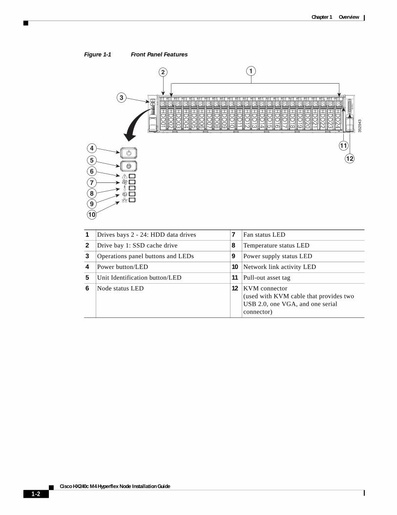
Figure 1-1 Front Panel Features
1 Drives bays 2 - 24: HDD data drives 7 Fan status LED
2 Drive bay 1: SSD cache drive 8 Temperature status LED
3 Operations panel buttons and LEDs 9 Power supply status LED
4 Power button/LED 10 Network link activity LED
5 Unit Identification button/LED 11 Pull-out asset tag
6 Node status LED 12 KVM connector (used with KVM cable that provides two USB 2.0, one VGA, and one serial connector)
3529
43
7
11
12
8
9
10
6
5
4
3
1
HD
D01
HD
D02
HD
D03
HD
D04
HD
D05
HD
D06
HD
D07
HD
D08
HD
D09
HD
D10
HD
D11
HD
D12
HD
D13
HD
D14
HD
D15
HD
D16
HD
D17
HD
D18
HD
D19
HD
D20
HD
D21
HD
D22
HD
D23
HD
D24
2
1-2Cisco HX240c M4 Hyperflex Node Installation Guide
Chapter 1 Overview
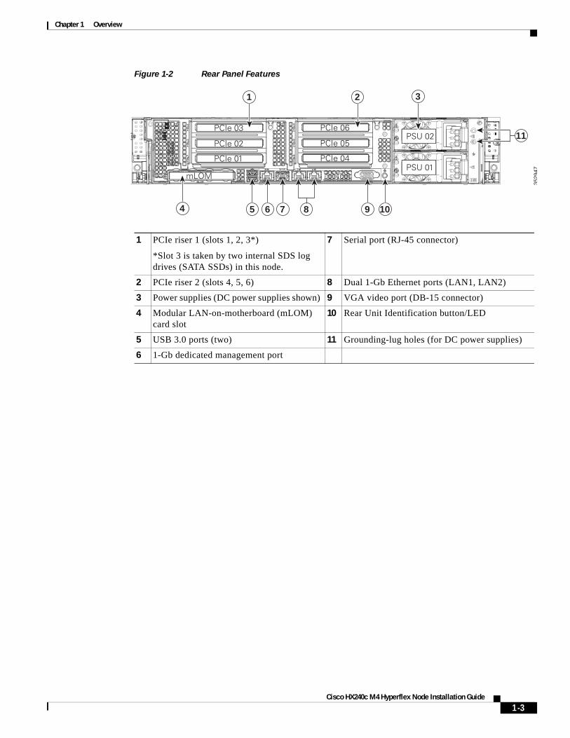
Figure 1-2 Rear Panel Features
1 PCIe riser 1 (slots 1, 2, 3*)
*Slot 3 is taken by two internal SDS log drives (SATA SSDs) in this node.
7 Serial port (RJ-45 connector)
2 PCIe riser 2 (slots 4, 5, 6) 8 Dual 1-Gb Ethernet ports (LAN1, LAN2)
3 Power supplies (DC power supplies shown) 9 VGA video port (DB-15 connector)
4 Modular LAN-on-motherboard (mLOM) card slot
10 Rear Unit Identification button/LED
5 USB 3.0 ports (two) 11 Grounding-lug holes (for DC power supplies)
6 1-Gb dedicated management port
3529
47
PCIe 01
PCIe 03
PCIe 02
mLOM
PCIe 04
PCIe 06
PCIe 05
PSU 01
PSU 02
4 5 6 7 9 10
11
1 2 3
8
1-3Cisco HX240c M4 Hyperflex Node Installation Guide
Chapter 1 Overview
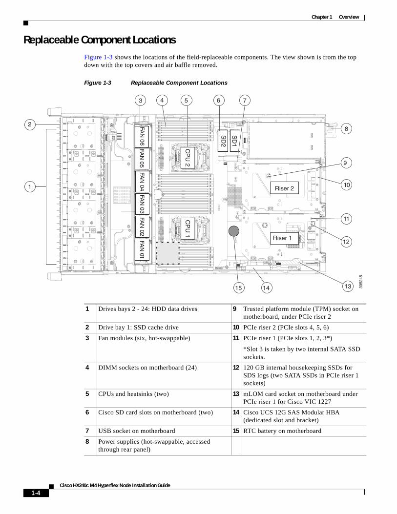
Replaceable Component Locations Figure 1-3 shows the locations of the field-replaceable components. The view shown is from the top down with the top covers and air baffle removed.
Figure 1-3 Replaceable Component Locations
1 Drives bays 2 - 24: HDD data drives 9 Trusted platform module (TPM) socket on motherboard, under PCIe riser 2
2 Drive bay 1: SSD cache drive 10 PCIe riser 2 (PCIe slots 4, 5, 6)
3 Fan modules (six, hot-swappable) 11 PCIe riser 1 (PCIe slots 1, 2, 3*)
*Slot 3 is taken by two internal SATA SSD sockets.
4 DIMM sockets on motherboard (24) 12 120 GB internal housekeeping SSDs for SDS logs (two SATA SSDs in PCIe riser 1 sockets)
5 CPUs and heatsinks (two) 13 mLOM card socket on motherboard under PCIe riser 1 for Cisco VIC 1227
6 Cisco SD card slots on motherboard (two) 14 Cisco UCS 12G SAS Modular HBA (dedicated slot and bracket)
7 USB socket on motherboard 15 RTC battery on motherboard
8 Power supplies (hot-swappable, accessed through rear panel)
3052
45
FAN
06
1
3 4 5 6
8
9
10
11
131415
FAN
05FA
N 04
FAN
03FA
N 02
FAN
01
CP
U 1
CP
U 2
SD
1
SD
2
Riser 2
Riser 112
7
2
1-4Cisco HX240c M4 Hyperflex Node Installation Guide
Chapter 1 Overview
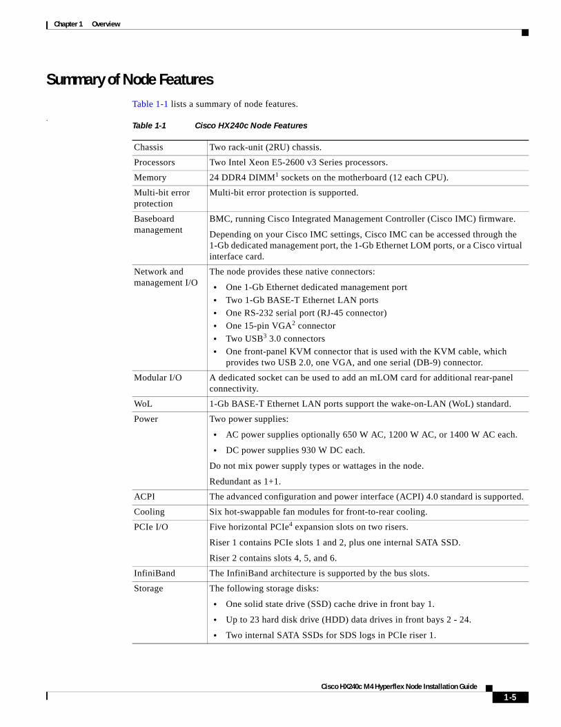
Summary of Node FeaturesTable 1-1 lists a summary of node features.
.Table 1-1 Cisco HX240c Node Features
Chassis Two rack-unit (2RU) chassis.
Processors Two Intel Xeon E5-2600 v3 Series processors.
Memory 24 DDR4 DIMM1 sockets on the motherboard (12 each CPU).
Multi-bit error protection
Multi-bit error protection is supported.
Baseboard management
BMC, running Cisco Integrated Management Controller (Cisco IMC) firmware.
Depending on your Cisco IMC settings, Cisco IMC can be accessed through the 1-Gb dedicated management port, the 1-Gb Ethernet LOM ports, or a Cisco virtual interface card.
Network and management I/O
The node provides these native connectors:
• One 1-Gb Ethernet dedicated management port
• Two 1-Gb BASE-T Ethernet LAN ports
• One RS-232 serial port (RJ-45 connector)
• One 15-pin VGA2 connector
• Two USB3 3.0 connectors
• One front-panel KVM connector that is used with the KVM cable, which provides two USB 2.0, one VGA, and one serial (DB-9) connector.
Modular I/O A dedicated socket can be used to add an mLOM card for additional rear-panel connectivity.
WoL 1-Gb BASE-T Ethernet LAN ports support the wake-on-LAN (WoL) standard.
Power Two power supplies:
• AC power supplies optionally 650 W AC, 1200 W AC, or 1400 W AC each.
• DC power supplies 930 W DC each.
Do not mix power supply types or wattages in the node.
Redundant as 1+1.
ACPI The advanced configuration and power interface (ACPI) 4.0 standard is supported.
Cooling Six hot-swappable fan modules for front-to-rear cooling.
PCIe I/O Five horizontal PCIe4 expansion slots on two risers.
Riser 1 contains PCIe slots 1 and 2, plus one internal SATA SSD.
Riser 2 contains slots 4, 5, and 6.
InfiniBand The InfiniBand architecture is supported by the bus slots.
Storage The following storage disks:
• One solid state drive (SSD) cache drive in front bay 1.
• Up to 23 hard disk drive (HDD) data drives in front bays 2 - 24.
• Two internal SATA SSDs for SDS logs in PCIe riser 1.
1-5Cisco HX240c M4 Hyperflex Node Installation Guide
Chapter 1 Overview
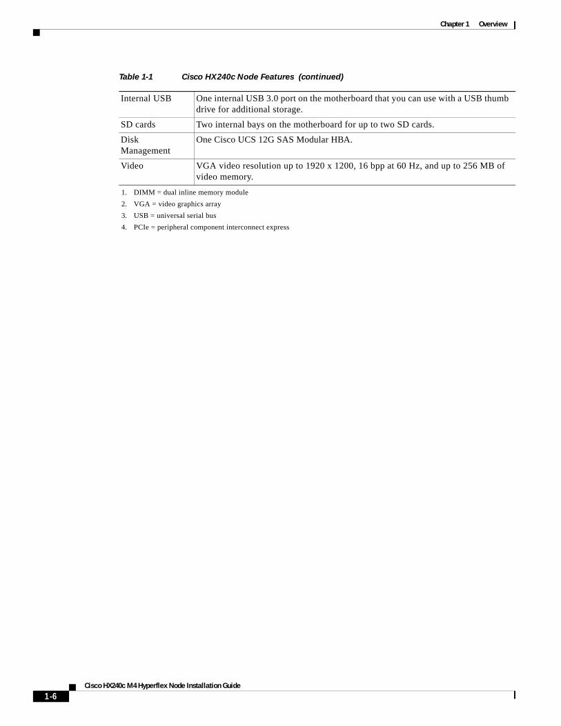
Internal USB One internal USB 3.0 port on the motherboard that you can use with a USB thumb drive for additional storage.
SD cards Two internal bays on the motherboard for up to two SD cards.
Disk Management
One Cisco UCS 12G SAS Modular HBA.
Video VGA video resolution up to 1920 x 1200, 16 bpp at 60 Hz, and up to 256 MB of video memory.
1. DIMM = dual inline memory module
2. VGA = video graphics array
3. USB = universal serial bus
4. PCIe = peripheral component interconnect express
Table 1-1 Cisco HX240c Node Features (continued)
1-6Cisco HX240c M4 Hyperflex Node Installation Guide
C
C H A P T E R 2
Installing the NodeThis chapter describes how to install the node, and it includes the following sections:
• Unpacking and Inspecting the Node, page 2-2
• Preparing for Node Installation, page 2-3
• Installing the Node In a Rack, page 2-5
• Initial Node Setup, page 2-10
• NIC Modes and NIC Redundancy Settings, page 2-14
• Node BIOS and Cisco IMC Firmware, page 2-15
• Updating the BIOS and Cisco IMC Firmware, page 2-15
Note Before you install, operate, or service a node, review the Regulatory Compliance and Safety Information for Cisco UCS C-Series Servers for important safety information.
Warning IMPORTANT SAFETY INSTRUCTIONS
This warning symbol means danger. You are in a situation that could cause bodily injury. Before you work on any equipment, be aware of the hazards involved with electrical circuitry and be familiar with standard practices for preventing accidents. Use the statement number provided at the end of each warning to locate its translation in the translated safety warnings that accompanied this device. Statement 1071
2-1isco HX240c M4 Hyperflex Node Installation Guide
Chapter 2 Installing the NodeUnpacking and Inspecting the Node
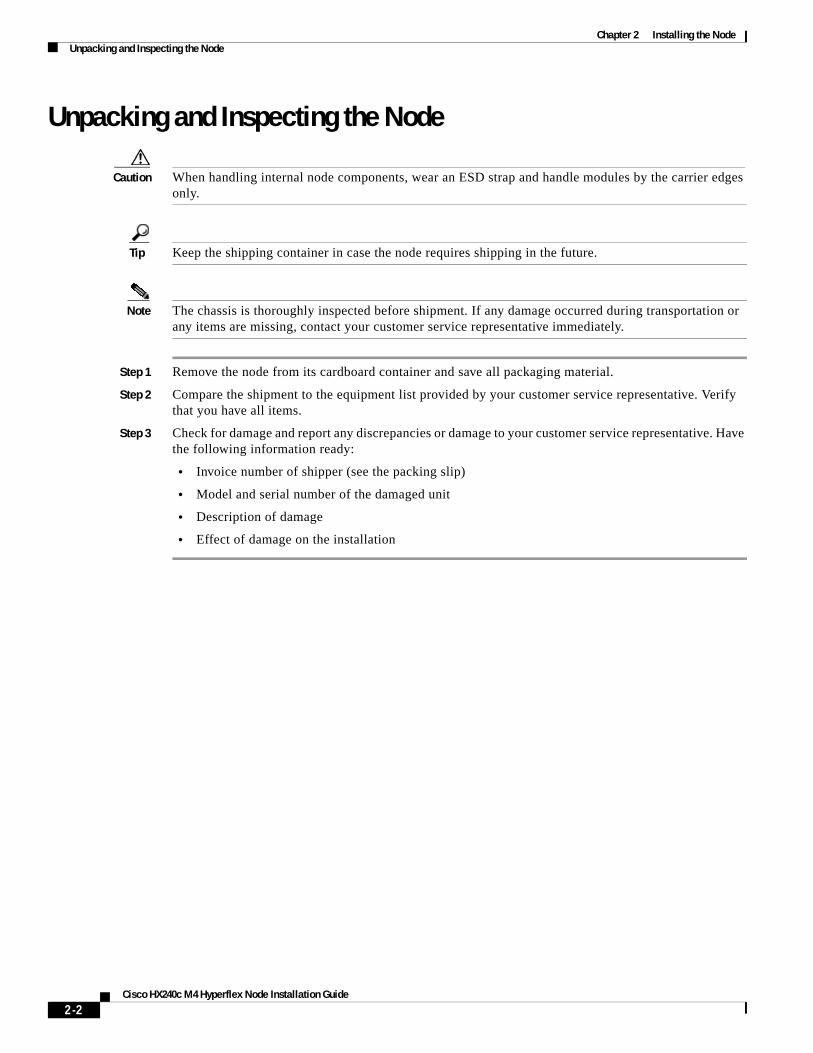
Unpacking and Inspecting the Node
Caution When handling internal node components, wear an ESD strap and handle modules by the carrier edges only.
Tip Keep the shipping container in case the node requires shipping in the future.
Note The chassis is thoroughly inspected before shipment. If any damage occurred during transportation or any items are missing, contact your customer service representative immediately.
Step 1 Remove the node from its cardboard container and save all packaging material.
Step 2 Compare the shipment to the equipment list provided by your customer service representative. Verify that you have all items.
Step 3 Check for damage and report any discrepancies or damage to your customer service representative. Have the following information ready:
• Invoice number of shipper (see the packing slip)
• Model and serial number of the damaged unit
• Description of damage
• Effect of damage on the installation
2-2Cisco HX240c M4 Hyperflex Node Installation Guide
Chapter 2 Installing the NodePreparing for Node Installation
Preparing for Node InstallationThis section provides information about preparing for node installation, and it includes the following topics:
• Installation Guidelines, page 2-3
• Rack Requirements, page 2-4
• Equipment Requirements, page 2-4
• Slide Rail Adjustment Range and Cable Management Arm Dimensions, page 2-4
Installation Guidelines
Warning To prevent the node from overheating, do not operate it in an area that exceeds the maximum recommended ambient temperature of: 35° C (95° F). Statement 1047
Warning The plug-socket combination must be accessible at all times, because it serves as the main disconnecting device.Statement 1019
Warning This product relies on the building’s installation for short-circuit (overcurrent) protection. Ensure that the protective device is rated not greater than: 250 V, 15 A.Statement 1005
Warning Installation of the equipment must comply with local and national electrical codes.Statement 1074
Caution To ensure proper airflow it is necessary to rack the nodes using rail kits. Physically placing the units on top of one another or “stacking” without the use of the rail kits blocks the air vents on top of the nodes, which could result in overheating, higher fan speeds, and higher power consumption. We recommend that you mount your nodes on rail kits when you are installing them into the rack because these rails provide the minimal spacing required between the nodes. No additional spacing between the nodes is required when you mount the units using rail kits.
2-3Cisco HX240c M4 Hyperflex Node Installation Guide
Chapter 2 Installing the NodePreparing for Node Installation
When you are installing a node, use the following guidelines:
• Ensure that there is adequate space around the node to allow for servicing the node and for adequate airflow. The airflow in this node is from front to back.
• Ensure that the air-conditioning meets the thermal requirements listed in the Node Specifications, page A-1.
• Ensure that the cabinet or rack meets the requirements listed in the “Rack Requirements” section on page 2-4.
• Ensure that the site power meets the power requirements listed in the Node Specifications, page A-1. If available, you can use an uninterruptible power supply (UPS) to protect against power failures.
Rack RequirementsThis section provides the requirements for the standard open racks.
The rack must be of the following type:
• A standard 19-in. (48.3-cm) wide, four-post EIA rack, with mounting posts that conform to English universal hole spacing, per section 1 of ANSI/EIA-310-D-1992.
• The rack post holes can be square 0.38-inch (9.6 mm), round 0.28-inch (7.1 mm), #12-24 UNC, or #10-32 UNC when you use the supplied slide rails.
• The minimum vertical rack space per node must be two RUs, equal to 3.5 in. (88.9 mm).
Equipment RequirementsThe slide rails supplied by Cisco for this node do not require tools for installation if you install them in a rack that has square 0.38-inch (9.6 mm), round 0.28-inch (7.1 mm), or #12-24 UNC threaded holes.
Supported Slide Rail KitsThis node supports one rail kit option: Cisco part UCSC-RAILB-M4= (ball-bearing rail kit).
Slide Rail Adjustment Range and Cable Management Arm DimensionsThe slide rails for this node have an adjustment range of 26 to 36 inches (660 to 914 mm).
The optional cable management arm (CMA) adds additional length requirements:
• The additional distance from the rear of the node to the rear of the CMA is 5.4 inches (137.4 mm)
• The total length of the node including the CMA is 34.4 inches (874 mm).
2-4Cisco HX240c M4 Hyperflex Node Installation Guide
Chapter 2 Installing the NodeInstalling the Node In a Rack
Installing the Node In a RackThis section contains the following sections:
• Installing the Slide Rails, page 2-5
• Installing the Cable Management Arm (Optional), page 2-8
• Reversing the Cable Management Arm (Optional), page 2-9
Installing the Slide RailsThis section describes how to install the node in a rack using the rack kits that are sold by Cisco.
Warning To prevent bodily injury when mounting or servicing this unit in a rack, you must take special precautions to ensure that the node remains stable. The following guidelines are provided to ensure your safety:This unit should be mounted at the bottom of the rack if it is the only unit in the rack.When mounting this unit in a partially filled rack, load the rack from the bottom to the top with the heaviest component at the bottom of the rack.If the rack is provided with stabilizing devices, install the stabilizers before mounting or servicing the unit in the rack. Statement 1006
Step 1 Attach the inner rails to the sides of the node:
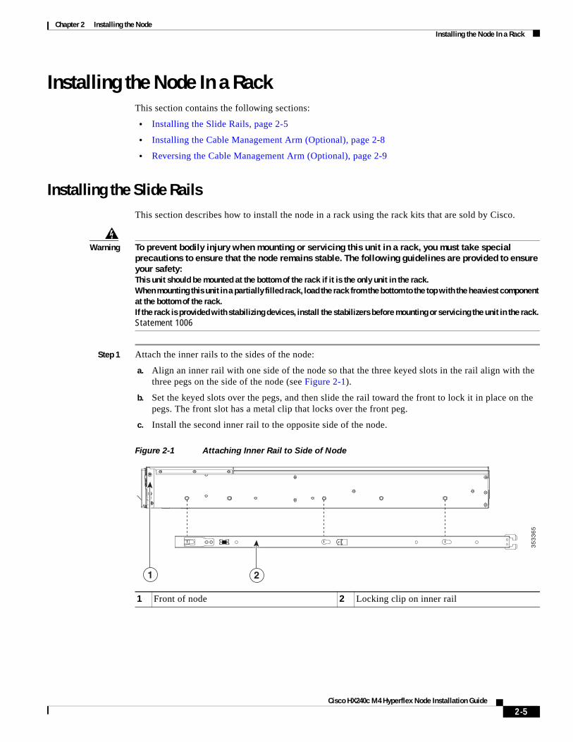
a. Align an inner rail with one side of the node so that the three keyed slots in the rail align with the three pegs on the side of the node (see Figure 2-1).
b. Set the keyed slots over the pegs, and then slide the rail toward the front to lock it in place on the pegs. The front slot has a metal clip that locks over the front peg.
c. Install the second inner rail to the opposite side of the node.
Figure 2-1 Attaching Inner Rail to Side of Node
1 Front of node 2 Locking clip on inner rail
35
33
65
1 2
2-5Cisco HX240c M4 Hyperflex Node Installation Guide
Chapter 2 Installing the NodeInstalling the Node In a Rack
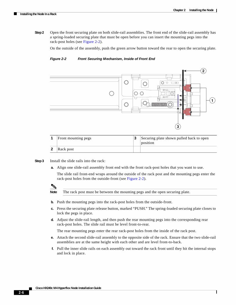
Step 2 Open the front securing plate on both slide-rail assemblies. The front end of the slide-rail assembly has a spring-loaded securing plate that must be open before you can insert the mounting pegs into the rack-post holes (see Figure 2-2).
On the outside of the assembly, push the green arrow button toward the rear to open the securing plate.
Figure 2-2 Front Securing Mechanism, Inside of Front End
Step 3 Install the slide rails into the rack:
a. Align one slide-rail assembly front end with the front rack-post holes that you want to use.
The slide rail front-end wraps around the outside of the rack post and the mounting pegs enter the rack-post holes from the outside-front (see Figure 2-2).
Note The rack post must be between the mounting pegs and the open securing plate.
b. Push the mounting pegs into the rack-post holes from the outside-front.
c. Press the securing plate release button, marked “PUSH.” The spring-loaded securing plate closes to lock the pegs in place.
d. Adjust the slide-rail length, and then push the rear mounting pegs into the corresponding rear rack-post holes. The slide rail must be level front-to-rear.
The rear mounting pegs enter the rear rack-post holes from the inside of the rack post.
e. Attach the second slide-rail assembly to the opposite side of the rack. Ensure that the two slide-rail assemblies are at the same height with each other and are level front-to-back.
f. Pull the inner slide rails on each assembly out toward the rack front until they hit the internal stops and lock in place.
1 Front mounting pegs 3 Securing plate shown pulled back to open position
2 Rack post
1
2
3
2-6Cisco HX240c M4 Hyperflex Node Installation Guide
Chapter 2 Installing the NodeInstalling the Node In a Rack
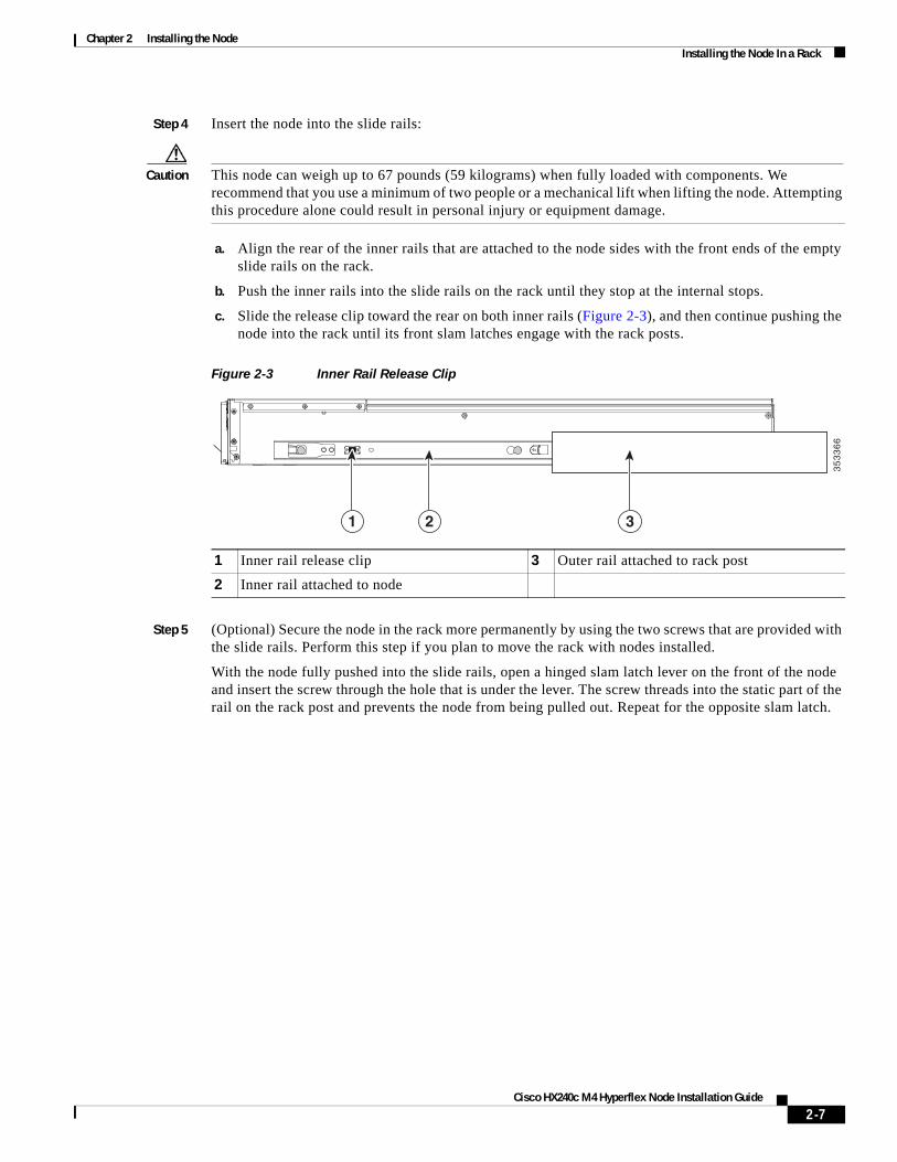
Step 4 Insert the node into the slide rails:
Caution This node can weigh up to 67 pounds (59 kilograms) when fully loaded with components. We recommend that you use a minimum of two people or a mechanical lift when lifting the node. Attempting this procedure alone could result in personal injury or equipment damage.
a. Align the rear of the inner rails that are attached to the node sides with the front ends of the empty slide rails on the rack.
b. Push the inner rails into the slide rails on the rack until they stop at the internal stops.
c. Slide the release clip toward the rear on both inner rails (Figure 2-3), and then continue pushing the node into the rack until its front slam latches engage with the rack posts.
Figure 2-3 Inner Rail Release Clip
Step 5 (Optional) Secure the node in the rack more permanently by using the two screws that are provided with the slide rails. Perform this step if you plan to move the rack with nodes installed.
With the node fully pushed into the slide rails, open a hinged slam latch lever on the front of the node and insert the screw through the hole that is under the lever. The screw threads into the static part of the rail on the rack post and prevents the node from being pulled out. Repeat for the opposite slam latch.
1 Inner rail release clip 3 Outer rail attached to rack post
2 Inner rail attached to node
35
33
66
1 2 3
2-7Cisco HX240c M4 Hyperflex Node Installation Guide
Chapter 2 Installing the NodeInstalling the Node In a Rack
Installing the Cable Management Arm (Optional)
Note The CMA is reversible left to right. To reverse the CMA, see Reversing the Cable Management Arm (Optional), page 2-9 before installation.
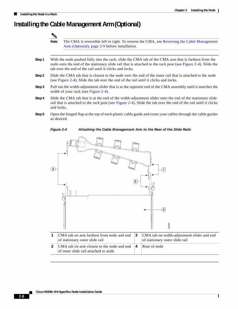
Step 1 With the node pushed fully into the rack, slide the CMA tab of the CMA arm that is farthest from the node onto the end of the stationary slide rail that is attached to the rack post (see Figure 2-4). Slide the tab over the end of the rail until it clicks and locks.
Step 2 Slide the CMA tab that is closest to the node over the end of the inner rail that is attached to the node (see Figure 2-4). Slide the tab over the end of the rail until it clicks and locks.
Step 3 Pull out the width-adjustment slider that is at the opposite end of the CMA assembly until it matches the width of your rack (see Figure 2-4).
Step 4 Slide the CMA tab that is at the end of the width-adjustment slider onto the end of the stationary slide rail that is attached to the rack post (see Figure 2-4). Slide the tab over the end of the rail until it clicks and locks.
Step 5 Open the hinged flap at the top of each plastic cable guide and route your cables through the cable guides as desired.
Figure 2-4 Attaching the Cable Management Arm to the Rear of the Slide Rails
1 CMA tab on arm farthest from node and end of stationary outer slide rail
3 CMA tab on width-adjustment slider and end of stationary outer slide rail
2 CMA tab on arm closest to the node and end of inner slide rail attached to node
4 Rear of node
3525
841
4
2
3
2-8Cisco HX240c M4 Hyperflex Node Installation Guide
Chapter 2 Installing the NodeInstalling the Node In a Rack
Reversing the Cable Management Arm (Optional)
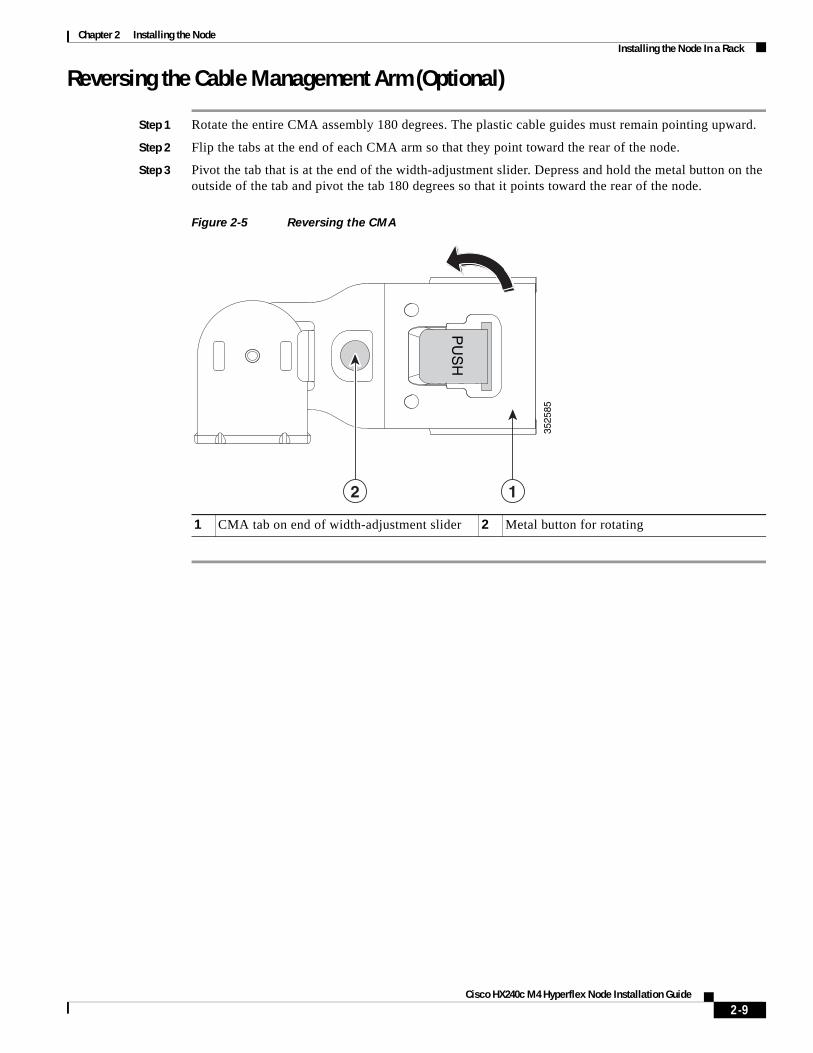
Step 1 Rotate the entire CMA assembly 180 degrees. The plastic cable guides must remain pointing upward.
Step 2 Flip the tabs at the end of each CMA arm so that they point toward the rear of the node.
Step 3 Pivot the tab that is at the end of the width-adjustment slider. Depress and hold the metal button on the outside of the tab and pivot the tab 180 degrees so that it points toward the rear of the node.
Figure 2-5 Reversing the CMA
1 CMA tab on end of width-adjustment slider 2 Metal button for rotating
3525
85
12
PU
SH
2-9Cisco HX240c M4 Hyperflex Node Installation Guide
Chapter 2 Installing the NodeInitial Node Setup
Initial Node Setup
Connecting and Powering On the Node (Standalone Mode)The node is shipped with these default settings:
• The NIC mode is Shared LOM EXT.
Shared LOM EXT mode enables the 1-Gb Ethernet ports and the ports on any installed Cisco virtual interface card (VIC) to access Cisco Integrated Management Interface (Cisco IMC). If you want to use the 10/100/1000 dedicated management ports to access Cisco IMC, you can connect to the node and change the NIC mode as described in Step 1 of the following procedure.
• The NIC redundancy is active-active. All Ethernet ports are utilized simultaneously.
• DHCP is enabled.
• IPv4 is enabled. You can change this to IPv6.
There are two methods for connecting to the node for initial setup:
• Local setup—Use this procedure if you want to connect a keyboard and monitor to the node for setup. This procedure requires a KVM cable (Cisco PID N20-BKVM). See Local Connection Procedure, page 2-10.
• Remote setup—Use this procedure if you want to perform setup through your dedicated management LAN. See Remote Connection Procedure, page 2-11.
Note To configure the node remotely, you must have a DHCP server on the same network as the node. Your DHCP server must be preconfigured with the range of MAC addresses for this node. The MAC address is printed on a label that is on the pull-out asset tag on the front panel (see Figure 1-1). This node has a range of six MAC addresses assigned to the Cisco IMC. The MAC address printed on the label is the beginning of the range of six contiguous MAC addresses.
Local Connection Procedure
Step 1 Attach a power cord to each power supply in your node, and then attach each power cord to a grounded AC power outlet. See Power Specifications, page A-2for power specifications.
Wait for approximately two minutes to let the node boot in standby power during the first bootup.
You can verify node power status by looking at the node Power Status LED on the front panel (see External Features Overview, page 1-1). The node is in standby power mode when the LED is amber.
Step 2 Connect a USB keyboard and VGA monitor to the node using one of the following methods:
• Connect a USB keyboard and VGA monitor to the corresponding connectors on the rear panel (see External Features Overview, page 1-1).
• Connect an optional KVM cable (Cisco PID N20-BKVM) to the KVM connector on the front panel (see External Features Overview, page 1-1 for the connector location). Connect your USB keyboard and VGA monitor to the KVM cable.
Step 3 Open the Cisco IMC Configuration Utility:
a. Press and hold the front panel power button for four seconds to boot the node.
b. During bootup, press F8 when prompted to open the Cisco IMC Configuration Utility.
This utility has two windows that you can switch between by pressing F1 or F2.
2-10Cisco HX240c M4 Hyperflex Node Installation Guide
Chapter 2 Installing the NodeInitial Node Setup
Step 4 Continue with Cisco IMC Configuration Utility Setup, page 2-12.
Remote Connection Procedure
Step 1 Attach a power cord to each power supply in your node, and then attach each power cord to a grounded AC power outlet.
Wait for approximately two minutes to let the node boot in standby power during the first bootup.
You can verify node power status by looking at the node Power Status LED on the front panel (see External Features Overview, page 1-1). The node is in standby power mode when the LED is amber.
Step 2 Plug your management Ethernet cable into the dedicated management port on the rear panel (see External Features Overview, page 1-1).
Step 3 Allow your preconfigured DHCP server to assign an IP address to the node.
Step 4 Use the assigned IP address to access and log in to the Cisco IMC for the node. Consult with your DHCP server administrator to determine the IP address.
Note The default user name for the node is admin. The default password is password.
Step 5 From the Cisco IMC Summary page, click Launch KVM Console. A separate KVM console window opens.
Step 6 From the Cisco IMC Summary page, click Power Cycle System. The node reboots.
Step 7 Select the KVM console window.
Note The KVM console window must be the active window for the following keyboard actions to work.
Step 8 When prompted, press F8 to enter the Cisco IMC Configuration Utility. This utility opens in the KVM console window.
This utility has two windows that you can switch between by pressing F1 or F2.
Step 9 Continue with Cisco IMC Configuration Utility Setup, page 2-12.
2-11Cisco HX240c M4 Hyperflex Node Installation Guide
Chapter 2 Installing the NodeInitial Node Setup
Cisco IMC Configuration Utility Setup
The following procedure is performed after you connect to the node and open the Cisco IMC Configuration Utility.
Step 1 Set NIC mode and NIC redundancy:
a. Set the NIC mode to choose which ports to use to access Cisco IMC for node management (see Figure 1-2 for identification of the ports):
• Shared LOM EXT (default)—This is the shared LOM extended mode, the factory-default setting. With this mode, the shared LOM and Cisco Card interfaces are both enabled.
In this mode, DHCP replies are returned to both the shared LOM ports and the Cisco card ports. If the node determines that the Cisco card connection is not getting its IP address from a Cisco UCS Manager node because the node is in standalone mode, further DHCP requests from the Cisco card are disabled. Use the Cisco Card NIC mode if you want to connect to Cisco IMC through a Cisco card in standalone mode.
• Dedicated—The dedicated management port is used to access Cisco IMC. You must select a NIC redundancy and IP setting.
• Shared LOM—The 1-Gb Ethernet ports are used to access Cisco IMC. You must select a NIC redundancy and IP setting.
• Cisco Card—The ports on an installed Cisco UCS virtual interface card (VIC) are used to access Cisco IMC. You must select a NIC redundancy and IP setting.
See also the required VIC Slot setting below.
• VIC Slot—If you use the Cisco Card NIC mode, you must select this setting to match where your VIC is installed. The choices are Riser1, Riser2, or Flex-LOM (the mLOM slot).
– If you select Riser1, slot 2 is the primary slot, but you can use slot 1.
– If you select Riser2, slot 5 is the primary slot, but you can use slot 4.
– If you select Flex-LOM, you must use an mLOM-style VIC in the mLOM slot.
b. Use this utility to change the NIC redundancy to your preference. This node has three possible NIC redundancy settings:
– None—The Ethernet ports operate independently and do not fail over if there is a problem. This setting can be used only with the Dedicated NIC mode.
– Active-standby—If an active Ethernet port fails, traffic fails over to a standby port.
– Active-active—All Ethernet ports are utilized simultaneously. Shared LOM EXT mode can have only this NIC redundancy setting. Shared LOM and Cisco Card modes can have both Active-standby and Active-active settings.
Step 2 Choose whether to enable DHCP for dynamic network settings, or to enter static network settings.
Note Before you enable DHCP, you must preconfigure your DHCP server with the range of MAC addresses for this node. The MAC address is printed on a label on the rear of the node. This node has a range of six MAC addresses assigned to Cisco IMC. The MAC address printed on the label is the beginning of the range of six contiguous MAC addresses.
The static IPv4 and IPv6 settings include the following:
• The Cisco IMC IP address.
• The prefix/subnet.
For IPv6, valid values are 1–127.
2-12Cisco HX240c M4 Hyperflex Node Installation Guide
Chapter 2 Installing the NodeInitial Node Setup
• The gateway.
For IPv6, if you do not know the gateway, you can set it as none by entering :: (two colons).
• The preferred DNS node address.
For IPv6, you can set this as none by entering :: (two colons).
Step 3 (Optional) Use this utility to make VLAN settings.
Step 4 Press F1 to go to the second settings window, then continue with the next step.
From the second window, you can press F2 to switch back to the first window.
Step 5 (Optional) Set a hostname for the node.
Step 6 (Optional) Enable dynamic DNS and set a dynamic DNS (DDNS) domain.
Step 7 (Optional) If you check the Factory Default check box, the node reverts to the factory defaults.
Step 8 (Optional) Set a default user password.
Step 9 (Optional) Enable auto-negotiation of port settings or set the port speed and duplex mode manually.
Note Auto-negotiation is applicable only when you use the Dedicated NIC mode. Auto-negotiation sets the port speed and duplex mode automatically based on the switch port to which the node is connected. If you disable auto-negotiation, you must set the port speed and duplex mode manually.
Step 10 (Optional) Reset port profiles and the port name.
Step 11 Press F5 to refresh the settings that you made. You might have to wait about 45 seconds until the new settings appear and the message, “Network settings configured” is displayed before you reboot the node in the next step.
Step 12 Press F10 to save your settings and reboot the node.
Note If you chose to enable DHCP, the dynamically assigned IP and MAC addresses are displayed on the console screen during bootup.
Use a browser and the IP address of the Cisco IMC to connect to the Cisco IMC management interface. The IP address is based upon the settings that you made (either a static address or the address assigned by your DHCP server).
Note The default username for the node is admin. The default password is password.
2-13Cisco HX240c M4 Hyperflex Node Installation Guide

Chapter 2 Installing the NodeNIC Modes and NIC Redundancy Settings
NIC Modes and NIC Redundancy Settings
NIC ModesThis node has the following NIC mode settings that you can choose from:
• Shared LOM EXT (default)—This mode is the shared LOM extended mode that is the factory-default setting. With this mode, the shared LOM and Cisco Card interfaces are both enabled.
In this mode, DHCP replies are returned to both the shared LOM ports and the Cisco card ports. If the node determines that the Cisco card connection is not getting its IP address from a Cisco UCS Manager node because the node is in standalone mode, further DHCP requests from the Cisco card are disabled. If the node determines that the Cisco card connection is getting its IP address from a Cisco UCS Manager node, the reply has parameters that automatically move the node to UCSM mode.
• Dedicated—The dedicated management port is used to access Cisco IMC. You must select a NIC redundancy and IP setting.
• Shared LOM—The 1-Gb Ethernet ports are used to access Cisco IMC. You must select a NIC redundancy and IP setting.
• Cisco Card—The ports on an installed Cisco UCS virtual interface card (VIC) are used to access Cisco IMC. You must select a NIC redundancy and IP setting.
See also the required VIC Slot setting below.
• VIC Slot—If you use the Cisco Card NIC mode, you select this setting to match where your VIC is installed. The choices are Riser1, Riser2, or Flex-LOM (the mLOM slot).
– If you select Riser1, slot 2 is the primary slot, but you can also use slot 1.
– If you select Riser2, slot 5 is the primary slot, but you can also use slot 4.
– If you select Flex-LOM, you must use an mLOM-style VIC in the mLOM slot.
NIC RedundancyThis node has the following NIC redundancy settings that you can choose from:
– None—The Ethernet ports operate independently and do not fail over if there is a problem. This setting can be used only with the Dedicated NIC mode.
– Active-standby—If an active Ethernet port fails, traffic fails over to a standby port.
– Active-active—All Ethernet ports are utilized simultaneously. Shared LOM EXT mode can have only this NIC redundancy setting. Shared LOM and Cisco Card modes can have both Active-standby and Active-active settings.
The active/active setting uses Mode 5 or Balance-TLB (adaptive transmit load balancing). This is channel bonding that does not require any special switch support. The outgoing traffic is distributed according to the current load (computed relative to the speed) on each slave. Incoming traffic is received by the current slave. If the receiving slave fails, another slave takes over the MAC address of the failed receiving slave.
2-14Cisco HX240c M4 Hyperflex Node Installation Guide
Chapter 2 Installing the NodeNode BIOS and Cisco IMC Firmware
Cisco HX240c M4 Hyperflex Node Installation Guide
Node BIOS and Cisco IMC FirmwareThis section includes information about the node BIOS and it includes the following sections:
• Updating the BIOS and Cisco IMC Firmware, page 2-15
• Accessing the Node BIOS, page 2-16
Updating the BIOS and Cisco IMC Firmware
Caution When you upgrade the BIOS firmware, you must also upgrade Cisco IMC firmware to the same version or the node will not boot. Do not power on the node until the BIOS and Cisco IMC firmware are matching or the node does not boot.
Cisco provides the Cisco Host Upgrade Utility to assist with simultaneously upgrading the BIOS, Cisco IMC, and other firmware to compatible levels.
The node uses firmware obtained from and certified by Cisco. Cisco provides release notes with each firmware image. There are several methods for updating the firmware:
• Recommended method for node components firmware update: Use the Cisco Host Upgrade Utility to simultaneously upgrade Cisco IMC, BIOS, LOM, LSI storage controller, and Cisco UCS VIC firmware to compatible levels.
See the Cisco Host Upgrade Utility Quick Reference Guide for your firmware level at the documentation roadmap link below.
• You can upgrade the BIOS using the EFI interface, or upgrade from a Windows or Linux platform.
See the Cisco UCS C-Series Rack-Mount Server BIOS Upgrade Guide.
• You can upgrade Cisco IMC and BIOS firmware by using the Cisco IMC GUI interface.
See the Cisco UCS C-Series Rack-Mount Server Configuration Guide.
• You can upgrade Cisco IMC and BIOS firmware by using the Cisco IMC CLI interface.
See the Cisco UCS C-Series Rack-Mount Server CLI Configuration Guide.
For links to the documents listed above, see the documentation roadmap at the following URL:
http://www.cisco.com/go/unifiedcomputing/c-series-doc
2-15
Chapter 2 Installing the NodeNode BIOS and Cisco IMC Firmware
Accessing the Node BIOS You can change the BIOS settings for your node. Detailed instructions are also printed on the BIOS screens.
Step 1 Enter the BIOS setup utility by pressing the F2 key when prompted during bootup.
Note The version and build of the current BIOS are displayed on the Main page of the utility.
Step 2 Use the arrow keys to select the BIOS menu page.
Step 3 Highlight the field to be modified by using the arrow keys.
Step 4 Press Enter to select the field that you want to change, and then modify the value in the field.
Step 5 Press the right arrow key until the Exit menu screen is displayed.
Step 6 Follow the instructions on the Exit menu screen to save your changes and exit the setup utility (or Press F10). You can exit without saving changes by pressing Esc.
2-16Cisco HX240c M4 Hyperflex Node Installation Guide
C
C H A P T E R 3
Maintaining the NodeThis chapter describes how to diagnose node problems using LEDs. It also provides information about how to install or replace hardware components, and it includes the following sections:
• Status LEDs and Buttons, page 3-1
• Preparing for Component Installation, page 3-8
• Installing or Replacing Node Components, page 3-11
• Service DIP Switches, page 3-47
Status LEDs and ButtonsThis section describes the location and meaning of LEDs and buttons and includes the following topics
• Front Panel LEDs, page 3-2
• Rear Panel LEDs and Buttons, page 3-4
• Internal Diagnostic LEDs, page 3-7
3-1isco HX240c M4 Hyperflex Node Installation Guide
Chapter 3 Maintaining the NodeStatus LEDs and Buttons
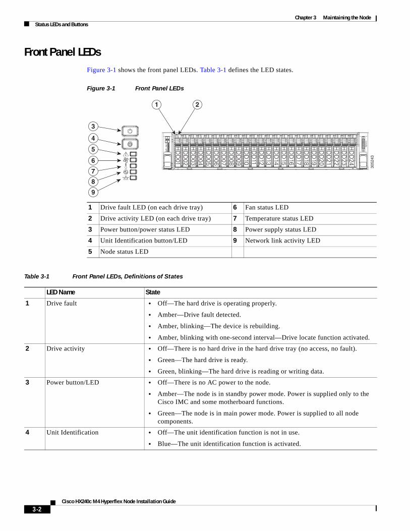
Front Panel LEDsFigure 3-1 shows the front panel LEDs. Table 3-1 defines the LED states.
Figure 3-1 Front Panel LEDs
1 Drive fault LED (on each drive tray) 6 Fan status LED
2 Drive activity LED (on each drive tray) 7 Temperature status LED
3 Power button/power status LED 8 Power supply status LED
4 Unit Identification button/LED 9 Network link activity LED
5 Node status LED
Table 3-1 Front Panel LEDs, Definitions of States
LED Name State
1 Drive fault • Off—The hard drive is operating properly.
• Amber—Drive fault detected.
• Amber, blinking—The device is rebuilding.
• Amber, blinking with one-second interval—Drive locate function activated.
2 Drive activity • Off—There is no hard drive in the hard drive tray (no access, no fault).
• Green—The hard drive is ready.
• Green, blinking—The hard drive is reading or writing data.
3 Power button/LED • Off—There is no AC power to the node.
• Amber—The node is in standby power mode. Power is supplied only to the Cisco IMC and some motherboard functions.
• Green—The node is in main power mode. Power is supplied to all node components.
4 Unit Identification • Off—The unit identification function is not in use.
• Blue—The unit identification function is activated.
3052
436
7
8
9
5
4
3
HD
D01
HD
D02
HD
D03
HD
D04
HD
D05
HD
D06
HD
D07
HD
D08
HD
D09
HD
D10
HD
D11
HD
D12
HD
D13
HD
D14
HD
D15
HD
D16
HD
D17
HD
D18
HD
D19
HD
D20
HD
D21
HD
D22
HD
D23
HD
D24
1 2
3-2Cisco HX240c M4 Hyperflex Node Installation Guide
Chapter 3 Maintaining the NodeStatus LEDs and Buttons
5 Node status • Green—The node is running in a normal operating condition.
• Green, blinking—The node is performing node initialization and memory check.
• Amber, steady—The node is in a degraded operational state. For example:
– Power supply redundancy is lost.
– CPUs are mismatched.
– At least one CPU is faulty.
– At least one DIMM is faulty.
– At least one drive in a RAID configuration failed.
• Amber, blinking—The node is in a critical fault state. For example:
– Boot failed.
– Fatal CPU and/or bus error is detected.
– Node is in an over-temperature condition.
6 Fan status • Green—All fan modules are operating properly.
• Amber, steady—One or more fan modules breached the critical threshold.
• Amber, blinking—One or more fan modules breached the non-recoverable threshold.
7 Temperature status • Green—The node is operating at normal temperature.
• Amber, steady—One or more temperature sensors breached the critical threshold.
• Amber, blinking—One or more temperature sensors breached the non-recoverable threshold.
8 Power supply status • Green—All power supplies are operating normally.
• Amber, steady—One or more power supplies are in a degraded operational state.
• Amber, blinking—One or more power supplies are in a critical fault state.
9 Network link activity • Off—The Ethernet link is idle.
• Green—One or more Ethernet LOM ports are link-active, but there is no activity.
• Green, blinking—One or more Ethernet LOM ports are link-active, with activity.
Table 3-1 Front Panel LEDs, Definitions of States (continued)
LED Name State
3-3Cisco HX240c M4 Hyperflex Node Installation Guide
Chapter 3 Maintaining the NodeStatus LEDs and Buttons
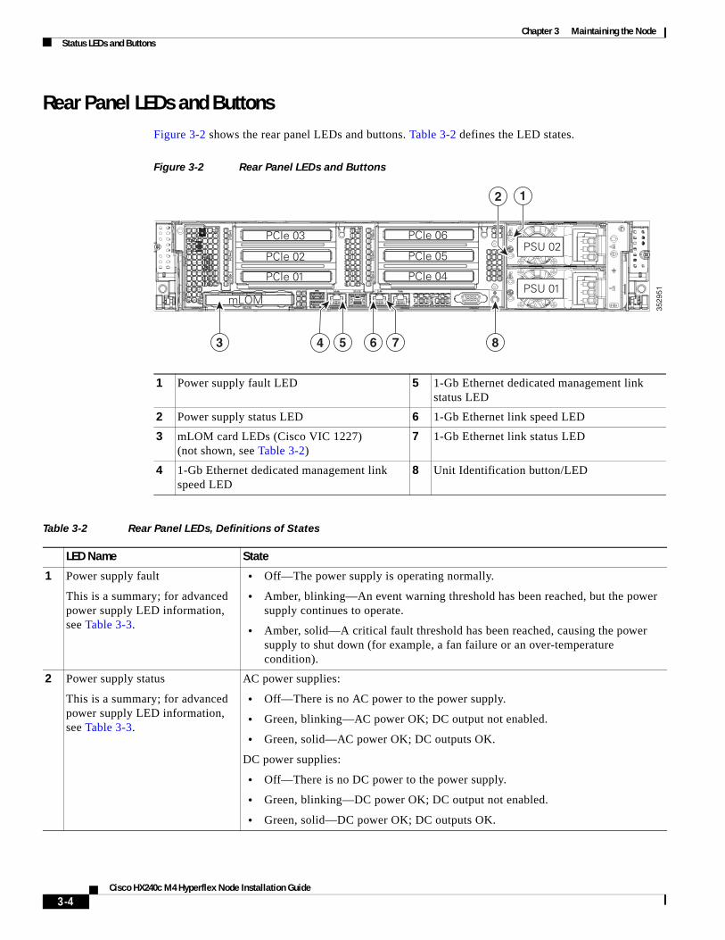
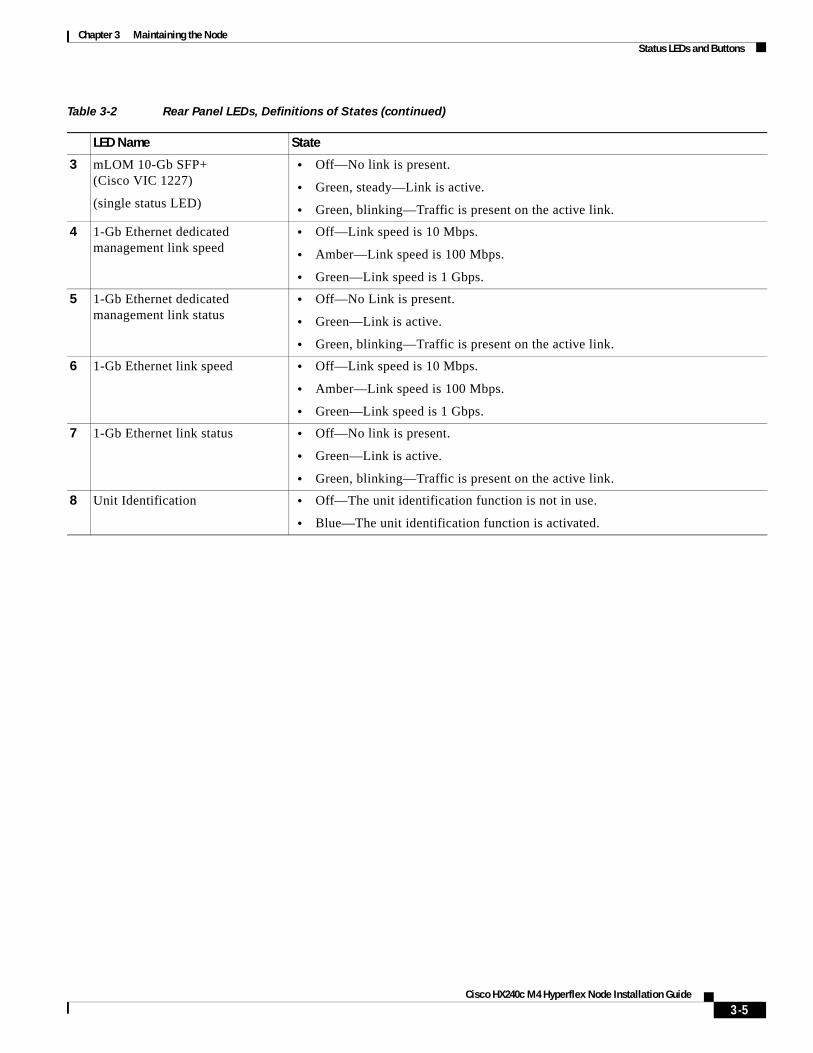
Rear Panel LEDs and ButtonsFigure 3-2 shows the rear panel LEDs and buttons. Table 3-2 defines the LED states.
Figure 3-2 Rear Panel LEDs and Buttons
1 Power supply fault LED 5 1-Gb Ethernet dedicated management link status LED
2 Power supply status LED 6 1-Gb Ethernet link speed LED
3 mLOM card LEDs (Cisco VIC 1227)(not shown, see Table 3-2)
7 1-Gb Ethernet link status LED
4 1-Gb Ethernet dedicated management link speed LED
8 Unit Identification button/LED
Table 3-2 Rear Panel LEDs, Definitions of States
LED Name State
1 Power supply fault
This is a summary; for advanced power supply LED information, see Table 3-3.
• Off—The power supply is operating normally.
• Amber, blinking—An event warning threshold has been reached, but the power supply continues to operate.
• Amber, solid—A critical fault threshold has been reached, causing the power supply to shut down (for example, a fan failure or an over-temperature condition).
2 Power supply status
This is a summary; for advanced power supply LED information, see Table 3-3.
AC power supplies:
• Off—There is no AC power to the power supply.
• Green, blinking—AC power OK; DC output not enabled.
• Green, solid—AC power OK; DC outputs OK.
DC power supplies:
• Off—There is no DC power to the power supply.
• Green, blinking—DC power OK; DC output not enabled.
• Green, solid—DC power OK; DC outputs OK.
3529
51
PCIe 01
PCIe 03
PCIe 02
mLOM
PCIe 04
PCIe 06
PCIe 05
PSU 01
PSU 02
4 73 6 85
12
3-4Cisco HX240c M4 Hyperflex Node Installation Guide
Chapter 3 Maintaining the NodeStatus LEDs and Buttons
3 mLOM 10-Gb SFP+ (Cisco VIC 1227)
(single status LED)
• Off—No link is present.
• Green, steady—Link is active.
• Green, blinking—Traffic is present on the active link.
4 1-Gb Ethernet dedicated management link speed
• Off—Link speed is 10 Mbps.
• Amber—Link speed is 100 Mbps.
• Green—Link speed is 1 Gbps.
5 1-Gb Ethernet dedicated management link status
• Off—No Link is present.
• Green—Link is active.
• Green, blinking—Traffic is present on the active link.
6 1-Gb Ethernet link speed • Off—Link speed is 10 Mbps.
• Amber—Link speed is 100 Mbps.
• Green—Link speed is 1 Gbps.
7 1-Gb Ethernet link status • Off—No link is present.
• Green—Link is active.
• Green, blinking—Traffic is present on the active link.
8 Unit Identification • Off—The unit identification function is not in use.
• Blue—The unit identification function is activated.
Table 3-2 Rear Panel LEDs, Definitions of States (continued)
LED Name State
3-5Cisco HX240c M4 Hyperflex Node Installation Guide
Chapter 3 Maintaining the NodeStatus LEDs and Buttons
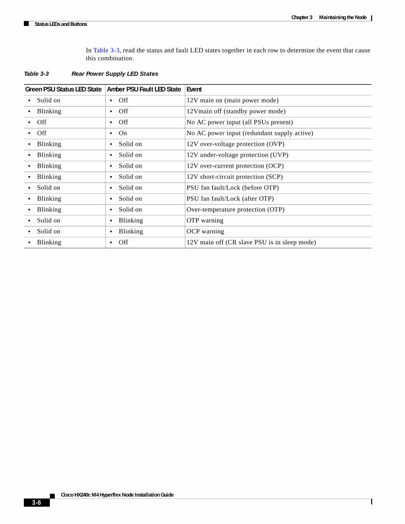
Cisco HX240c M4 Hyperflex Node Installation Guide
In Table 3-3, read the status and fault LED states together in each row to determine the event that cause this combination.
Table 3-3 Rear Power Supply LED States
Green PSU Status LED State Amber PSU Fault LED State Event
• Solid on • Off 12V main on (main power mode)
• Blinking • Off 12Vmain off (standby power mode)
• Off • Off No AC power input (all PSUs present)
• Off • On No AC power input (redundant supply active)
• Blinking • Solid on 12V over-voltage protection (OVP)
• Blinking • Solid on 12V under-voltage protection (UVP)
• Blinking • Solid on 12V over-current protection (OCP)
• Blinking • Solid on 12V short-circuit protection (SCP)
• Solid on • Solid on PSU fan fault/Lock (before OTP)
• Blinking • Solid on PSU fan fault/Lock (after OTP)
• Blinking • Solid on Over-temperature protection (OTP)
• Solid on • Blinking OTP warning
• Solid on • Blinking OCP warning
• Blinking • Off 12V main off (CR slave PSU is in sleep mode)
3-6
Chapter 3 Maintaining the NodeStatus LEDs and Buttons
Cisco HX240c M4 Hyperflex Node Installation Guide
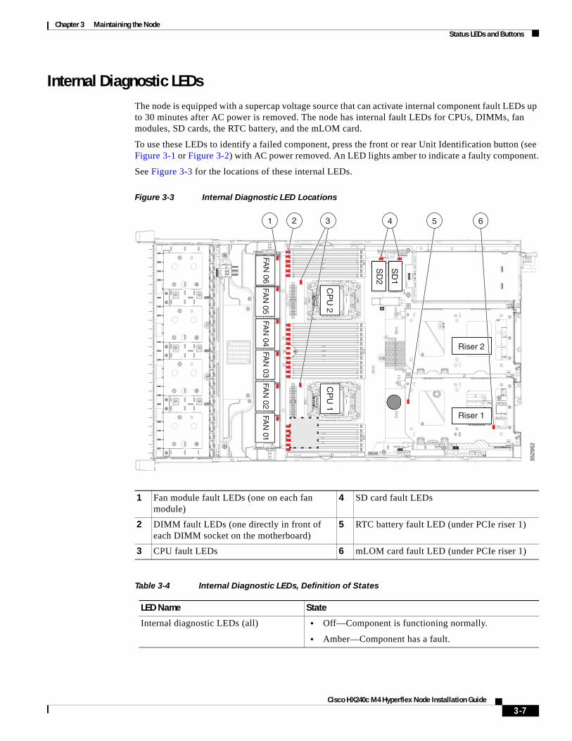
Internal Diagnostic LEDsThe node is equipped with a supercap voltage source that can activate internal component fault LEDs up to 30 minutes after AC power is removed. The node has internal fault LEDs for CPUs, DIMMs, fan modules, SD cards, the RTC battery, and the mLOM card.
To use these LEDs to identify a failed component, press the front or rear Unit Identification button (see Figure 3-1 or Figure 3-2) with AC power removed. An LED lights amber to indicate a faulty component.
See Figure 3-3 for the locations of these internal LEDs.
Figure 3-3 Internal Diagnostic LED Locations
1 Fan module fault LEDs (one on each fan module)
4 SD card fault LEDs
2 DIMM fault LEDs (one directly in front of each DIMM socket on the motherboard)
5 RTC battery fault LED (under PCIe riser 1)
3 CPU fault LEDs 6 mLOM card fault LED (under PCIe riser 1)
Table 3-4 Internal Diagnostic LEDs, Definition of States
LED Name State
Internal diagnostic LEDs (all) • Off—Component is functioning normally.
• Amber—Component has a fault.
3529
52
FAN
06
1 2 3
FAN
05FA
N 04
FAN
03FA
N 02
FAN
01
CP
U 1
CP
U 2
SD
1
SD
2
Riser 2
Riser 1
4 65
3-7
Chapter 3 Maintaining the NodePreparing for Component Installation
Preparing for Component InstallationThis section describes how to prepare for component installation, and it includes the following topics:
• Required Equipment, page 3-8
• Shutting Down and Powering Off the Node, page 3-8
• Removing and Replacing the Node Top Cover, page 3-9
• Serial Number Location, page 3-10
Required Equipment The following equipment is used to perform the procedures in this chapter:
• Number 2 Phillips-head screwdriver
• Electrostatic discharge (ESD) strap or other grounding equipment such as a grounded mat
Shutting Down and Powering Off the NodeThe node can run in two power modes:
• Main power mode—Power is supplied to all node components and any operating system on your drives can run.
• Standby power mode—Power is supplied only to the service processor and the cooling fans and it is safe to power off the node from this mode.
You can invoke a graceful shutdown or a hard shutdown by using either of the following methods:
• Use the Cisco IMC management interface.
• Use the Power button on the node front panel. To use the Power button, follow these steps:
Step 1 Check the color of the Power Status LED (see the “Front Panel LEDs” section on page 3-2).
• Green—The node is in main power mode and must be shut down before it can be safely powered off. Go to Step 2.
• Amber—The node is already in standby mode and can be safely powered off. Go to Step 3.
Step 2 Invoke either a graceful shutdown or a hard shutdown:
Caution To avoid data loss or damage to your operating system, you should always invoke a graceful shutdown of the operating system.
• Graceful shutdown—Press and release the Power button. The operating system performs a graceful shutdown and the node goes to standby mode, which is indicated by an amber Power Status LED.
• Emergency shutdown—Press and hold the Power button for 4 seconds to force the main power off and immediately enter standby mode.
Step 3 Disconnect the power cords from the power supplies in your node to completely power off the node.
3-8Cisco HX240c M4 Hyperflex Node Installation Guide
Chapter 3 Maintaining the NodePreparing for Component Installation
Removing and Replacing the Node Top Cover
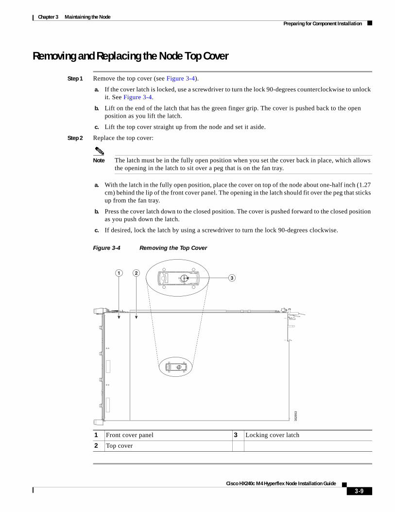
Step 1 Remove the top cover (see Figure 3-4).
a. If the cover latch is locked, use a screwdriver to turn the lock 90-degrees counterclockwise to unlock it. See Figure 3-4.
b. Lift on the end of the latch that has the green finger grip. The cover is pushed back to the open position as you lift the latch.
c. Lift the top cover straight up from the node and set it aside.
Step 2 Replace the top cover:
Note The latch must be in the fully open position when you set the cover back in place, which allows the opening in the latch to sit over a peg that is on the fan tray.
a. With the latch in the fully open position, place the cover on top of the node about one-half inch (1.27 cm) behind the lip of the front cover panel. The opening in the latch should fit over the peg that sticks up from the fan tray.
b. Press the cover latch down to the closed position. The cover is pushed forward to the closed position as you push down the latch.
c. If desired, lock the latch by using a screwdriver to turn the lock 90-degrees clockwise.
Figure 3-4 Removing the Top Cover
1 Front cover panel 3 Locking cover latch
2 Top cover
3529
53
1 23
3-9Cisco HX240c M4 Hyperflex Node Installation Guide

Chapter 3 Maintaining the NodePreparing for Component Installation
Serial Number LocationThe serial number (SN) for the node is printed on a label on the top of the node, near the front.
3-10Cisco HX240c M4 Hyperflex Node Installation Guide
Chapter 3 Maintaining the NodeInstalling or Replacing Node Components
Installing or Replacing Node Components
Warning Blank faceplates and cover panels serve three important functions: they prevent exposure to hazardous voltages and currents inside the chassis; they contain electromagnetic interference (EMI) that might disrupt other equipment; and they direct the flow of cooling air through the chassis. Do not operate the node unless all cards, faceplates, front covers, and rear covers are in place. Statement 1029
Caution When handling node components, wear an ESD strap to avoid damage.
Tip You can press the Unit Identification button on the front panel or rear panel to turn on a flashing Unit Identification LED on the front and rear panels of the node. This button allows you to locate the specific node that you are servicing when you go to the opposite side of the rack. You can also activate these LEDs remotely by using the Cisco IMC interface. See the “Status LEDs and Buttons” section on page 3-1 for locations of these LEDs.
This section describes how to install and replace node components, and it includes the following topics:
• Replaceable Component Locations, page 3-12
• Replacing Drives, page 3-13
• Replacing Fan Modules, page 3-16
• Replacing DIMMs, page 3-18
• Replacing CPUs and Heatsinks, page 3-22
• Replacing a Cisco Modular HBA Card, page 3-26
• Replacing the Motherboard RTC Battery, page 3-28
• Replacing an Internal SD Card, page 3-29
• Enabling or Disabling the Internal USB Port, page 3-30
• Replacing a PCIe Riser, page 3-31
• Replacing a PCIe Card, page 3-33
• Replacing the Internal Housekeeping SSDs for SDS Logs, page 3-38
• Installing a Trusted Platform Module, page 3-39
• Replacing Power Supplies, page 3-42
• Replacing an mLOM Card (Cisco VIC 1227), page 3-45
3-11Cisco HX240c M4 Hyperflex Node Installation Guide
Chapter 3 Maintaining the NodeInstalling or Replacing Node Components
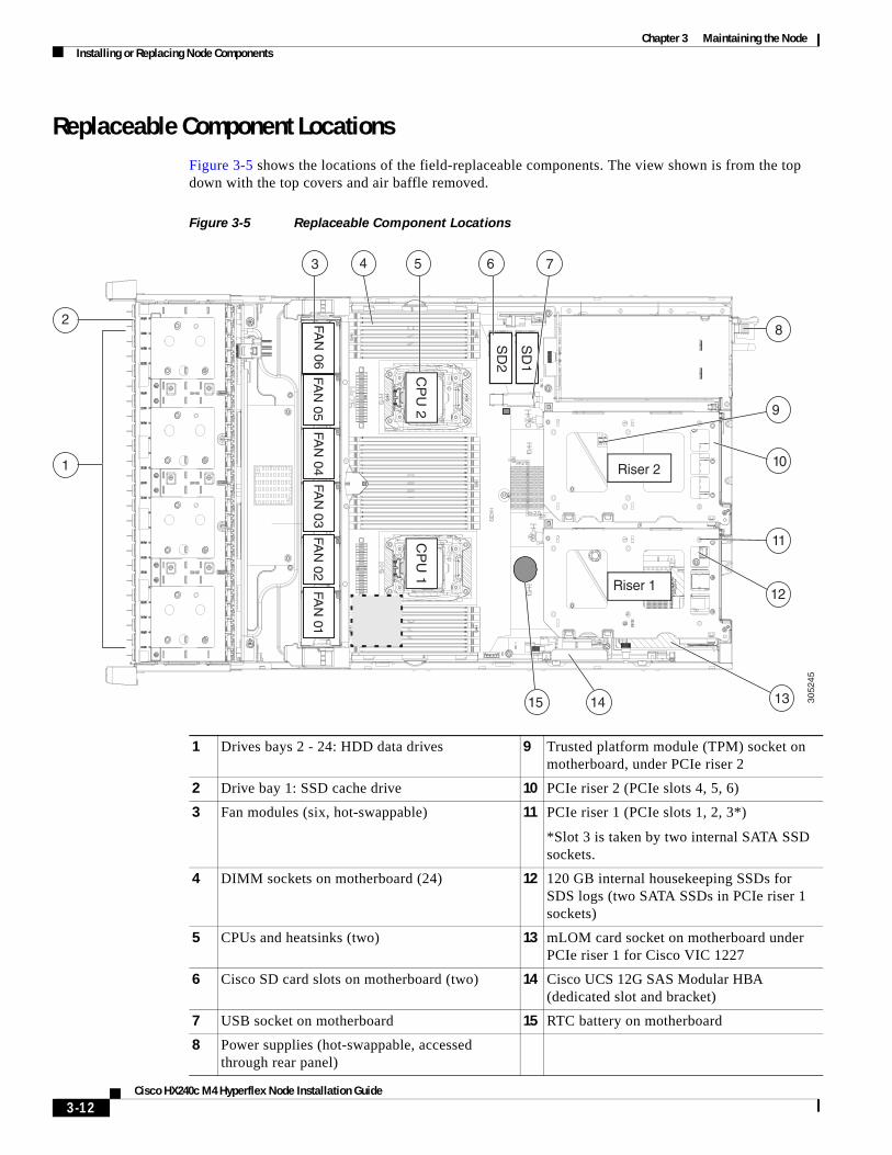
Replaceable Component Locations Figure 3-5 shows the locations of the field-replaceable components. The view shown is from the top down with the top covers and air baffle removed.
Figure 3-5 Replaceable Component Locations
1 Drives bays 2 - 24: HDD data drives 9 Trusted platform module (TPM) socket on motherboard, under PCIe riser 2
2 Drive bay 1: SSD cache drive 10 PCIe riser 2 (PCIe slots 4, 5, 6)
3 Fan modules (six, hot-swappable) 11 PCIe riser 1 (PCIe slots 1, 2, 3*)
*Slot 3 is taken by two internal SATA SSD sockets.
4 DIMM sockets on motherboard (24) 12 120 GB internal housekeeping SSDs for SDS logs (two SATA SSDs in PCIe riser 1 sockets)
5 CPUs and heatsinks (two) 13 mLOM card socket on motherboard under PCIe riser 1 for Cisco VIC 1227
6 Cisco SD card slots on motherboard (two) 14 Cisco UCS 12G SAS Modular HBA (dedicated slot and bracket)
7 USB socket on motherboard 15 RTC battery on motherboard
8 Power supplies (hot-swappable, accessed through rear panel)
3052
45
FAN
06
1
3 4 5 6
8
9
10
11
131415
FAN
05
FAN
04
FAN
03
FAN
02
FAN
01
CP
U 1
CP
U 2
SD
1
SD
2
Riser 2
Riser 112
7
2
3-12Cisco HX240c M4 Hyperflex Node Installation Guide
Chapter 3 Maintaining the NodeInstalling or Replacing Node Components
Replacing DrivesThis section includes the following information:
• Drive Population Guidelines, page 3-13
• Drive Replacement Overview, page 3-13
• Replacing HDD Data Drives (Bays 2 – 24), page 3-14
• Replacing the SSD Cache Drive (Bay 1), page 3-15
Drive Population Guidelines
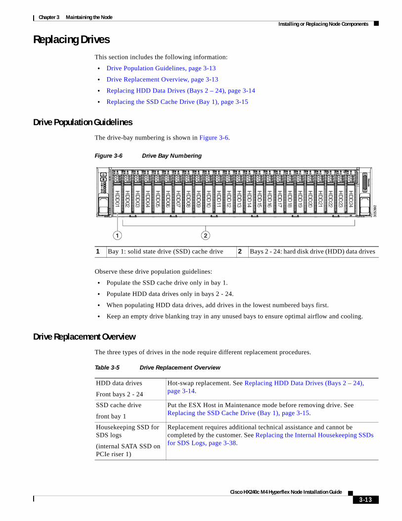
The drive-bay numbering is shown in Figure 3-6.
Figure 3-6 Drive Bay Numbering
Observe these drive population guidelines:
• Populate the SSD cache drive only in bay 1.
• Populate HDD data drives only in bays 2 - 24.
• When populating HDD data drives, add drives in the lowest numbered bays first.
• Keep an empty drive blanking tray in any unused bays to ensure optimal airflow and cooling.
Drive Replacement Overview
The three types of drives in the node require different replacement procedures.
1 Bay 1: solid state drive (SSD) cache drive 2 Bays 2 - 24: hard disk drive (HDD) data drives
Table 3-5 Drive Replacement Overview
HDD data drives
Front bays 2 - 24
Hot-swap replacement. See Replacing HDD Data Drives (Bays 2 – 24), page 3-14.
SSD cache drive
front bay 1
Put the ESX Host in Maintenance mode before removing drive. See Replacing the SSD Cache Drive (Bay 1), page 3-15.
Housekeeping SSD for SDS logs
(internal SATA SSD on PCIe riser 1)
Replacement requires additional technical assistance and cannot be completed by the customer. See Replacing the Internal Housekeeping SSDs for SDS Logs, page 3-38.
3-13Cisco HX240c M4 Hyperflex Node Installation Guide
Chapter 3 Maintaining the NodeInstalling or Replacing Node Components
Cisco HX240c M4 Hyperflex Node Installation Guide
Replacing HDD Data Drives (Bays 2 – 24)
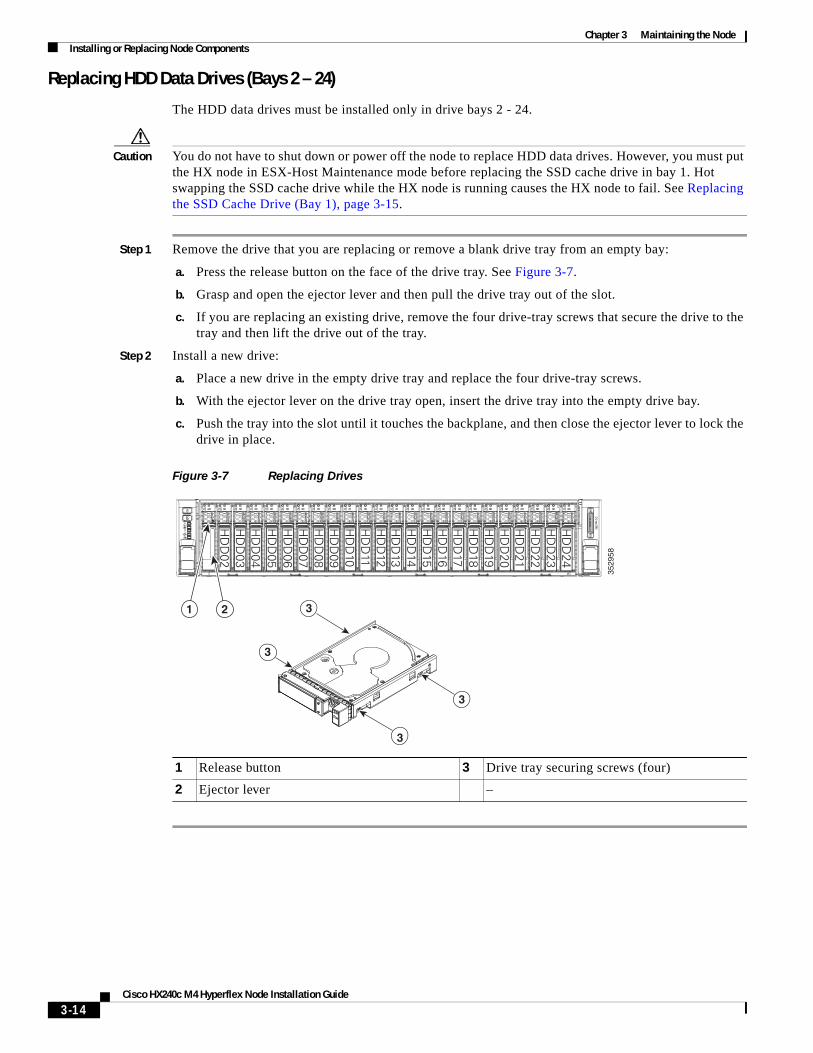
The HDD data drives must be installed only in drive bays 2 - 24.
Caution You do not have to shut down or power off the node to replace HDD data drives. However, you must put the HX node in ESX-Host Maintenance mode before replacing the SSD cache drive in bay 1. Hot swapping the SSD cache drive while the HX node is running causes the HX node to fail. See Replacing the SSD Cache Drive (Bay 1), page 3-15.
Step 1 Remove the drive that you are replacing or remove a blank drive tray from an empty bay:
a. Press the release button on the face of the drive tray. See Figure 3-7.
b. Grasp and open the ejector lever and then pull the drive tray out of the slot.
c. If you are replacing an existing drive, remove the four drive-tray screws that secure the drive to the tray and then lift the drive out of the tray.
Step 2 Install a new drive:
a. Place a new drive in the empty drive tray and replace the four drive-tray screws.
b. With the ejector lever on the drive tray open, insert the drive tray into the empty drive bay.
c. Push the tray into the slot until it touches the backplane, and then close the ejector lever to lock the drive in place.
Figure 3-7 Replacing Drives
1 Release button 3 Drive tray securing screws (four)
2 Ejector lever –
3529
58
HD
D02
HD
D03
HD
D04
HD
D05
HD
D06
HD
D07
HD
D08
HD
D09
HD
D10
HD
D11
HD
D12
HD
D13
HD
D14
HD
D15
HD
D16
HD
D17
HD
D18
HD
D19
HD
D20
HD
D21
HD
D22
HD
D23
HD
D24
3
3
3
3
21
3-14
Chapter 3 Maintaining the NodeInstalling or Replacing Node Components
Replacing the SSD Cache Drive (Bay 1)
The SSD cache drive must be installed in drive bay 1 (see Figure 3-6).
Caution Put the HX node in ESX-Host Maintenance mode before replacing the SSD cache drive, as described in the procedure. Hot swapping the SSD cache drive while the HX node is running causes the HX node to fail.
Step 1 Put the node in ESX-Host Maintenance mode by using the vCenter interface or the ESX host command line:
• Using the vCenter interface:
a. From vSphere, go to Home > Hosts and Clusters > Hosts > host.
b. Right-click each host and select Maintenance Mode > Enter Maintenance Mode.
• Using ESX host command line:
a. Log in to the ESX server host command line as a user with root privileges.
b. Move the ESX host into Maintenance mode.
# esxcli system maintenanceMode set -e true
Step 2 Remove the SSD cache drive:
a. Press the release button on the face of the drive tray (see Figure 3-7).
b. Grasp and open the ejector lever and then pull the drive tray out of the slot.
c. Remove the four drive-tray screws that secure the SSD to the tray and then lift the SSD out of the tray.
Step 3 Install a new drive:
a. Place a new SSD in the empty drive tray and replace the four drive-tray screws.
b. With the ejector lever on the drive tray open, insert the drive tray into the empty drive bay.
c. Push the tray into the slot until it touches the backplane, and then close the ejector lever to lock the drive in place.
Step 4 Take the node out of ESX-Host Maintenance mode.
3-15Cisco HX240c M4 Hyperflex Node Installation Guide
Chapter 3 Maintaining the NodeInstalling or Replacing Node Components
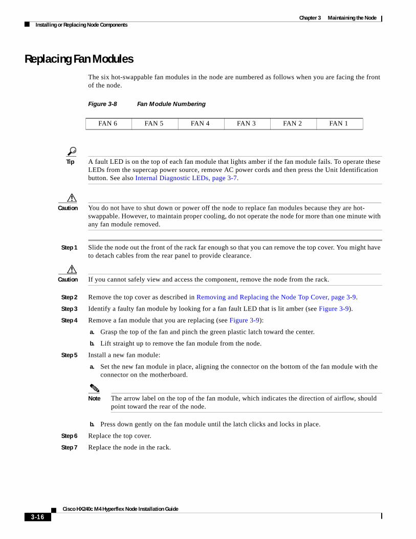
Replacing Fan Modules The six hot-swappable fan modules in the node are numbered as follows when you are facing the front of the node.
Figure 3-8 Fan Module Numbering
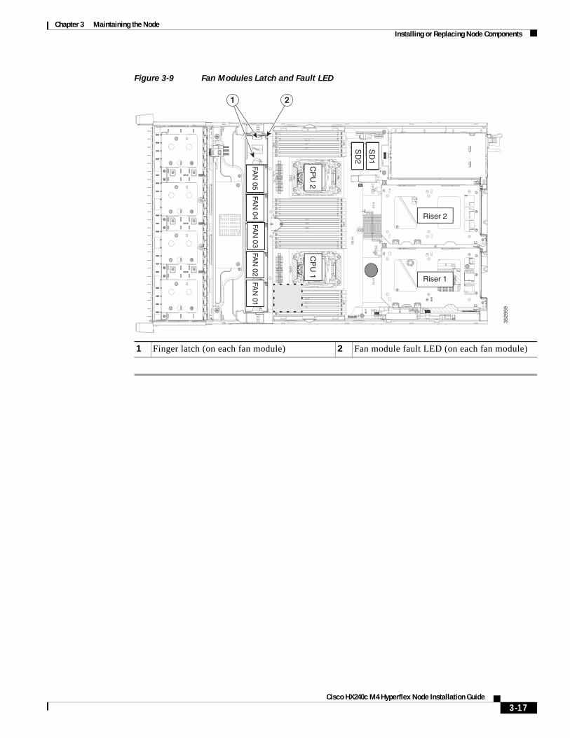
Tip A fault LED is on the top of each fan module that lights amber if the fan module fails. To operate these LEDs from the supercap power source, remove AC power cords and then press the Unit Identification button. See also Internal Diagnostic LEDs, page 3-7.
Caution You do not have to shut down or power off the node to replace fan modules because they are hot- swappable. However, to maintain proper cooling, do not operate the node for more than one minute with any fan module removed.
Step 1 Slide the node out the front of the rack far enough so that you can remove the top cover. You might have to detach cables from the rear panel to provide clearance.
Caution If you cannot safely view and access the component, remove the node from the rack.
Step 2 Remove the top cover as described in Removing and Replacing the Node Top Cover, page 3-9.
Step 3 Identify a faulty fan module by looking for a fan fault LED that is lit amber (see Figure 3-9).
Step 4 Remove a fan module that you are replacing (see Figure 3-9):
a. Grasp the top of the fan and pinch the green plastic latch toward the center.
b. Lift straight up to remove the fan module from the node.
Step 5 Install a new fan module:
a. Set the new fan module in place, aligning the connector on the bottom of the fan module with the connector on the motherboard.
Note The arrow label on the top of the fan module, which indicates the direction of airflow, should point toward the rear of the node.
b. Press down gently on the fan module until the latch clicks and locks in place.
Step 6 Replace the top cover.
Step 7 Replace the node in the rack.
FAN 6 FAN 5 FAN 4 FAN 3 FAN 2 FAN 1
3-16Cisco HX240c M4 Hyperflex Node Installation Guide
Chapter 3 Maintaining the NodeInstalling or Replacing Node Components
Figure 3-9 Fan Modules Latch and Fault LED
1 Finger latch (on each fan module) 2 Fan module fault LED (on each fan module)
3529
59
FAN
05FA
N 04
FAN
03FA
N 02
FAN
01
CP
U 1
CP
U 2
SD
1
SD
2Riser 2
Riser 1
1 2
3-17Cisco HX240c M4 Hyperflex Node Installation Guide
Chapter 3 Maintaining the NodeInstalling or Replacing Node Components
Replacing DIMMs This section includes the following topics:
• Memory Performance Guidelines and Population Rules, page 3-18
• DIMM Replacement Procedure, page 3-21
Caution DIMMs and their sockets are fragile and must be handled with care to avoid damage during installation.
Caution Cisco does not support third-party DIMMs. Using non-Cisco DIMMs in the node might result in node problems or damage to the motherboard.
Note To ensure the best node performance, it is important that you are familiar with memory performance guidelines and population rules before you install or replace the memory.
Memory Performance Guidelines and Population Rules
This section describes the type of memory that the node requires and its effect on performance. The section includes the following topics:
• DIMM Socket Numbering, page 3-19
• DIMM Population Rules, page 3-19
• Memory Mirroring and RAS, page 3-20
• Lockstep Channel Mode, page 3-20
3-18Cisco HX240c M4 Hyperflex Node Installation Guide
Chapter 3 Maintaining the NodeInstalling or Replacing Node Components
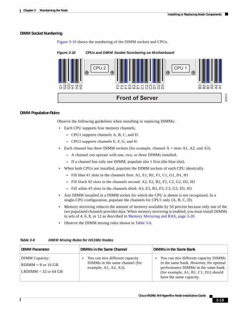
DIMM Socket Numbering
Figure 3-10 shows the numbering of the DIMM sockets and CPUs.
Figure 3-10 CPUs and DIMM Socket Numbering on Motherboard
DIMM Population Rules
Observe the following guidelines when installing or replacing DIMMs:
• Each CPU supports four memory channels.
– CPU1 supports channels A, B, C, and D.
– CPU2 supports channels E, F, G, and H.
• Each channel has three DIMM sockets (for example, channel A = slots A1, A2, and A3).
– A channel can operate with one, two, or three DIMMs installed.
– If a channel has only one DIMM, populate slot 1 first (the blue slot).
• When both CPUs are installed, populate the DIMM sockets of each CPU identically.
– Fill blue #1 slots in the channels first: A1, E1, B1, F1, C1, G1, D1, H1
– Fill black #2 slots in the channels second: A2, E2, B2, F2, C2, G2, D2, H2
– Fill white #3 slots in the channels third: A3, E3, B3, F3, C3, G3, D3, H3
• Any DIMM installed in a DIMM socket for which the CPU is absent is not recognized. In a single-CPU configuration, populate the channels for CPU1 only (A, B, C, D).
• Memory mirroring reduces the amount of memory available by 50 percent because only one of the two populated channels provides data. When memory mirroring is enabled, you must install DIMMs in sets of 4, 6, 8, or 12 as described in Memory Mirroring and RAS, page 3-20.
• Observe the DIMM mixing rules shown in Table 3-6.
Front of Server
CPU 2 CPU 1
B3
B2
B1
A3
A2
A1
C1
C2
C3
D1
D2
D3
F3 F2 F1 E3
E2
E1
G1
G2
G3
H1
H2
H3
3528
15
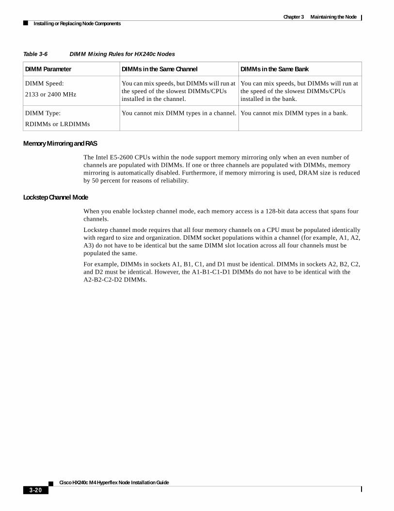
Table 3-6 DIMM Mixing Rules for HX240c Nodes
DIMM Parameter DIMMs in the Same Channel DIMMs in the Same Bank
DIMM Capacity:
RDIMM = 8 or 16 GB
LRDIMM = 32 or 64 GB
• You can mix different capacity DIMMs in the same channel (for example, A1, A2, A3).
• You can mix different capacity DIMMs in the same bank. However, for optimal performance DIMMs in the same bank (for example, A1, B1, C1, D1) should have the same capacity.
3-19Cisco HX240c M4 Hyperflex Node Installation Guide
Chapter 3 Maintaining the NodeInstalling or Replacing Node Components
Memory Mirroring and RAS
The Intel E5-2600 CPUs within the node support memory mirroring only when an even number of channels are populated with DIMMs. If one or three channels are populated with DIMMs, memory mirroring is automatically disabled. Furthermore, if memory mirroring is used, DRAM size is reduced by 50 percent for reasons of reliability.
Lockstep Channel Mode
When you enable lockstep channel mode, each memory access is a 128-bit data access that spans four channels.
Lockstep channel mode requires that all four memory channels on a CPU must be populated identically with regard to size and organization. DIMM socket populations within a channel (for example, A1, A2, A3) do not have to be identical but the same DIMM slot location across all four channels must be populated the same.
For example, DIMMs in sockets A1, B1, C1, and D1 must be identical. DIMMs in sockets A2, B2, C2, and D2 must be identical. However, the A1-B1-C1-D1 DIMMs do not have to be identical with the A2-B2-C2-D2 DIMMs.
DIMM Speed:
2133 or 2400 MHz
You can mix speeds, but DIMMs will run at the speed of the slowest DIMMs/CPUs installed in the channel.
You can mix speeds, but DIMMs will run at the speed of the slowest DIMMs/CPUs installed in the bank.
DIMM Type:
RDIMMs or LRDIMMs
You cannot mix DIMM types in a channel. You cannot mix DIMM types in a bank.
Table 3-6 DIMM Mixing Rules for HX240c Nodes
DIMM Parameter DIMMs in the Same Channel DIMMs in the Same Bank
3-20Cisco HX240c M4 Hyperflex Node Installation Guide
Chapter 3 Maintaining the NodeInstalling or Replacing Node Components
DIMM Replacement Procedure
This section includes the following topics:
• Identifying a Faulty DIMM, page 3-21
• Replacing DIMMs, page 3-21
Identifying a Faulty DIMM
Each DIMM socket has a corresponding DIMM fault LED, directly in front of the DIMM socket. See Figure 3-3 for the locations of these LEDs. The LEDs light amber to indicate a faulty DIMM. To operate these LEDs from the SuperCap power source, remove AC power cords and then press the Unit Identification button.
Replacing DIMMs
Step 1 Power off the node as described in Shutting Down and Powering Off the Node, page 3-8.
Step 2 Slide the node out the front of the rack far enough so that you can remove the top cover. You might have to detach cables from the rear panel to provide clearance.
Caution If you cannot safely view and access the component, remove the node from the rack.
Step 3 Remove the top cover as described in Removing and Replacing the Node Top Cover, page 3-9.
Step 4 Remove the air baffle that sits over the DIMM sockets and set it aside.
Step 5 Identify the faulty DIMM by observing the DIMM socket fault LEDs on the motherboard (see Figure 3-3).
Step 6 Remove the DIMMs that you are replacing. Open the ejector levers at both ends of the DIMM socket, and then lift the DIMM out of the socket.
Step 7 Install a new DIMM:
Note Before installing DIMMs, see the population guidelines. See Memory Performance Guidelines and Population Rules, page 3-18.
a. Align the new DIMM with the empty socket on the motherboard. Use the alignment key in the DIMM socket to correctly orient the DIMM.
b. Push down evenly on the top corners of the DIMM until it is fully seated and the ejector levers on both ends lock into place.
Step 8 Replace the air baffle.
Step 9 Replace the top cover.
Step 10 Replace the node in the rack, replace cables, and then power on the node by pressing the Power button.
3-21Cisco HX240c M4 Hyperflex Node Installation Guide
Chapter 3 Maintaining the NodeInstalling or Replacing Node Components
Replacing CPUs and Heatsinks This section contains the following topics:
• CPU Configuration Rules, page 3-22
• Replacing a CPU and Heatsink, page 3-22
• Additional CPU-Related Parts to Order with RMA Replacement Motherboards, page 3-25
CPU Configuration Rules
This node has two CPU sockets. Each CPU supports four DIMM channels (12 DIMM sockets). See Figure 3-10.
• The minimum configuration is that the node must have at two CPUs installed.
Replacing a CPU and Heatsink
Caution CPUs and their motherboard sockets are fragile and must be handled with care to avoid damaging pins during installation. The CPUs must be installed with heatsinks and their thermal grease to ensure proper cooling. Failure to install a CPU correctly might result in damage to the node.
Note This node uses the new independent loading mechanism (ILM) CPU sockets, so no Pick-and-Place tools are required for CPU handling or installation. Always grasp the plastic frame on the CPU when handling.
Step 1 Power off the node as described in Shutting Down and Powering Off the Node, page 3-8.
Step 2 Slide the node out the front of the rack far enough so that you can remove the top cover. You might have to detach cables from the rear panel to provide clearance.
Caution If you cannot safely view and access the component, remove the node from the rack.
Step 3 Remove the top cover as described in Removing and Replacing the Node Top Cover, page 3-9.
Step 4 Remove the plastic air baffle that sits over the CPUs.
Step 5 Remove the heatsink that you are replacing:
a. Use a Number 2 Phillips-head screwdriver to loosen the four captive screws that secure the heatsink.
Note Alternate loosening each screw evenly to avoid damaging the heatsink or CPU.
b. Lift the heatsink off of the CPU.
Step 6 Open the CPU retaining mechanism:
a. Unclip the first retaining latch labeled with the icon, and then unclip the second retaining latch labeled with the icon. See Figure 3-11.
b. Open the hinged CPU cover plate.
3-22Cisco HX240c M4 Hyperflex Node Installation Guide
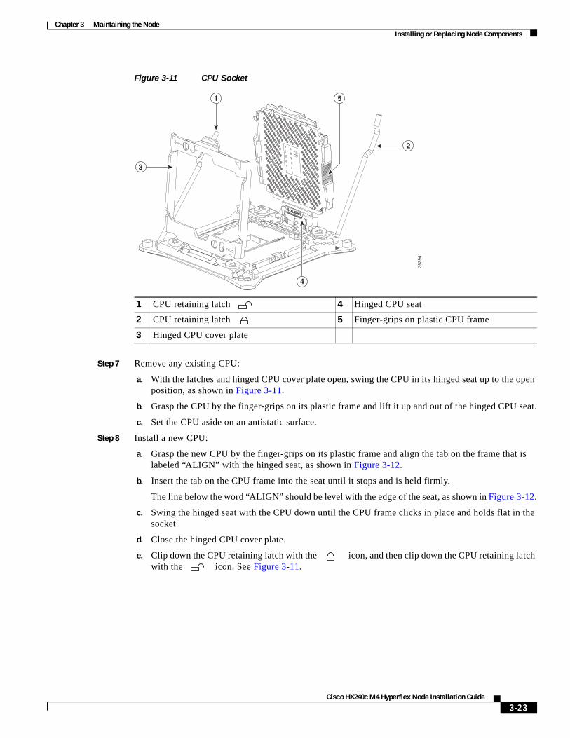
Chapter 3 Maintaining the NodeInstalling or Replacing Node Components
Figure 3-11 CPU Socket
Step 7 Remove any existing CPU:
a. With the latches and hinged CPU cover plate open, swing the CPU in its hinged seat up to the open position, as shown in Figure 3-11.
b. Grasp the CPU by the finger-grips on its plastic frame and lift it up and out of the hinged CPU seat.
c. Set the CPU aside on an antistatic surface.
Step 8 Install a new CPU:
a. Grasp the new CPU by the finger-grips on its plastic frame and align the tab on the frame that is labeled “ALIGN” with the hinged seat, as shown in Figure 3-12.
b. Insert the tab on the CPU frame into the seat until it stops and is held firmly.
The line below the word “ALIGN” should be level with the edge of the seat, as shown in Figure 3-12.
c. Swing the hinged seat with the CPU down until the CPU frame clicks in place and holds flat in the socket.
d. Close the hinged CPU cover plate.
e. Clip down the CPU retaining latch with the icon, and then clip down the CPU retaining latch with the icon. See Figure 3-11.
1 CPU retaining latch 4 Hinged CPU seat
2 CPU retaining latch 5 Finger-grips on plastic CPU frame
3 Hinged CPU cover plate
1
2
4
3
5
3529
41
3-23Cisco HX240c M4 Hyperflex Node Installation Guide
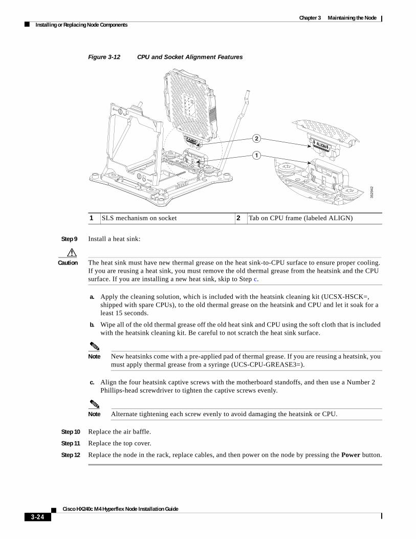
Chapter 3 Maintaining the NodeInstalling or Replacing Node Components
Figure 3-12 CPU and Socket Alignment Features
Step 9 Install a heat sink:
Caution The heat sink must have new thermal grease on the heat sink-to-CPU surface to ensure proper cooling. If you are reusing a heat sink, you must remove the old thermal grease from the heatsink and the CPU surface. If you are installing a new heat sink, skip to Step c.
a. Apply the cleaning solution, which is included with the heatsink cleaning kit (UCSX-HSCK=, shipped with spare CPUs), to the old thermal grease on the heatsink and CPU and let it soak for a least 15 seconds.
b. Wipe all of the old thermal grease off the old heat sink and CPU using the soft cloth that is included with the heatsink cleaning kit. Be careful to not scratch the heat sink surface.
Note New heatsinks come with a pre-applied pad of thermal grease. If you are reusing a heatsink, you must apply thermal grease from a syringe (UCS-CPU-GREASE3=).
c. Align the four heatsink captive screws with the motherboard standoffs, and then use a Number 2 Phillips-head screwdriver to tighten the captive screws evenly.
Note Alternate tightening each screw evenly to avoid damaging the heatsink or CPU.
Step 10 Replace the air baffle.
Step 11 Replace the top cover.
Step 12 Replace the node in the rack, replace cables, and then power on the node by pressing the Power button.
1 SLS mechanism on socket 2 Tab on CPU frame (labeled ALIGN)
2
1
3529
42
3-24Cisco HX240c M4 Hyperflex Node Installation Guide
Chapter 3 Maintaining the NodeInstalling or Replacing Node Components
Additional CPU-Related Parts to Order with RMA Replacement Motherboards
When a return material authorization (RMA) of the motherboard or CPU is done, additional parts might not be included with the CPU or motherboard spare bill of materials (BOM). The TAC engineer might need to add the additional parts to the RMA to help ensure a successful replacement.
Note This node uses the new independent loading mechanism (ILM) CPU sockets, so no Pick-and-Place tools are required for CPU handling or installation. Always grasp the plastic frame on the CPU when handling.
• Scenario 1—You are reusing the existing heatsinks:
– Heat sink cleaning kit (UCSX-HSCK=)
– Thermal grease kit for HX240c (UCS-CPU-GREASE3=)
• Scenario 2—You are replacing the existing heatsinks:
– Heat sink (UCSC-HS-C240M4=)
– Heat sink cleaning kit (UCSX-HSCK=)
A CPU heatsink cleaning kit is good for up to four CPU and heatsink cleanings. The cleaning kit contains two bottles of solution, one to clean the CPU and heatsink of old thermal interface material and the other to prepare the surface of the heatsink.
New heatsink spares come with a pre-applied pad of thermal grease. It is important to clean the old thermal grease off of the CPU prior to installing the heatsinks. Therefore, when you are ordering new heatsinks, you must order the heatsink cleaning kit.
3-25Cisco HX240c M4 Hyperflex Node Installation Guide
Chapter 3 Maintaining the NodeInstalling or Replacing Node Components
Replacing a Cisco Modular HBA CardThe node has an internal, dedicated PCIe slot on the motherboard for an HBA card (see Figure 3-13).
Step 1 Power off the node as described in Shutting Down and Powering Off the Node, page 3-8.
Step 2 Slide the node out the front of the rack far enough so that you can remove the top cover. You might have to detach cables from the rear panel to provide clearance.
Caution If you cannot safely view and access the component, remove the node from the rack.
Step 3 Remove the top cover as described in Removing and Replacing the Node Top Cover, page 3-9.
Step 4 Remove an existing RAID controller card:
a. Disconnect the data cable from the card. Depress the tab on the cable connector and pull.
b. Disconnect the supercap power module cable from the transportable memory module (TMM), if present.
c. Lift straight up on the metal bracket that holds the card. The bracket lifts off of two pegs on the chassis wall.
d. Loosen the two thumbscrews that hold the card to the metal bracket and then lift the card from the bracket.
Step 5 Install a new RAID controller card:
Caution When installing the card to the bracket, be careful so that you do not scrape and damage electronic components on the underside of the card on features of the bracket. Also avoid scraping the card when you install the bracket to the pegs on the chassis wall.
a. Set the new card on the metal bracket, aligned so that the thumbscrews on the card enter the threaded standoffs on the bracket. Tighten the thumbscrews to secure the card to the bracket.
b. Align the two slots on the back of the bracket with the two pegs on the chassis wall.
The two slots on the bracket must slide down over the pegs at the same time that you push the card into the motherboard socket.
c. Gently press down on both top corners of the metal bracket to seat the card into the socket on the motherboard.
d. Connect the supercap power module cable to its connector on the TMM, if present.
e. Connect the single data cable to the card.
Step 6 Replace the top cover.
Step 7 Replace the node in the rack, replace cables, and then power on the node by pressing the Power button.
3-26Cisco HX240c M4 Hyperflex Node Installation Guide
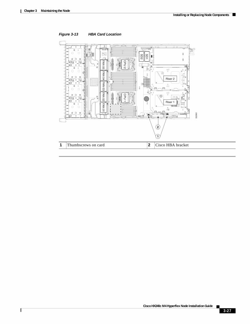
Chapter 3 Maintaining the NodeInstalling or Replacing Node Components
Figure 3-13 HBA Card Location
1 Thumbscrews on card 2 Cisco HBA bracket
3529
61
FAN
05FA
N 04
FAN
03FA
N 02
FAN
01
CP
U 1
CP
U 2
SD
1
SD
2
Riser 2
Riser 1
2
1
3-27Cisco HX240c M4 Hyperflex Node Installation Guide
Chapter 3 Maintaining the NodeInstalling or Replacing Node Components
Replacing the Motherboard RTC Battery
Warning There is danger of explosion if the battery is replaced incorrectly. Replace the battery only with the same or equivalent type recommended by the manufacturer. Dispose of used batteries according to the manufacturer’s instructions. [Statement 1015]
The real-time clock (RTC) battery retains node settings when the node is disconnected from power. The battery type is CR2032. Cisco supports the industry-standard CR2032 battery, which can be purchased from most electronic stores.
Step 1 Power off the node as described in Shutting Down and Powering Off the Node, page 3-8.
Step 2 Slide the node out the front of the rack far enough so that you can remove the top cover. You might have to detach cables from the rear panel to provide clearance.
Caution If you cannot safely view and access the component, remove the node from the rack.
Step 3 Remove the top cover as described in Removing and Replacing the Node Top Cover, page 3-9.
Step 4 Remove the battery from its holder on the motherboard (see Figure 3-14):
a. Use a small screwdriver or pointed object to press inward on the battery at the prying point (see Figure 3-14).
b. Lift up on the battery and remove it from the holder.
Step 5 Install an RTC battery. Insert the battery into its holder and press down until it clicks in place.
Note The positive side of the battery marked “3V+” should face upward.
Step 6 Replace the top cover.
Step 7 Replace the node in the rack, replace cables, and power on the node by pressing the Power button.
3-28Cisco HX240c M4 Hyperflex Node Installation Guide
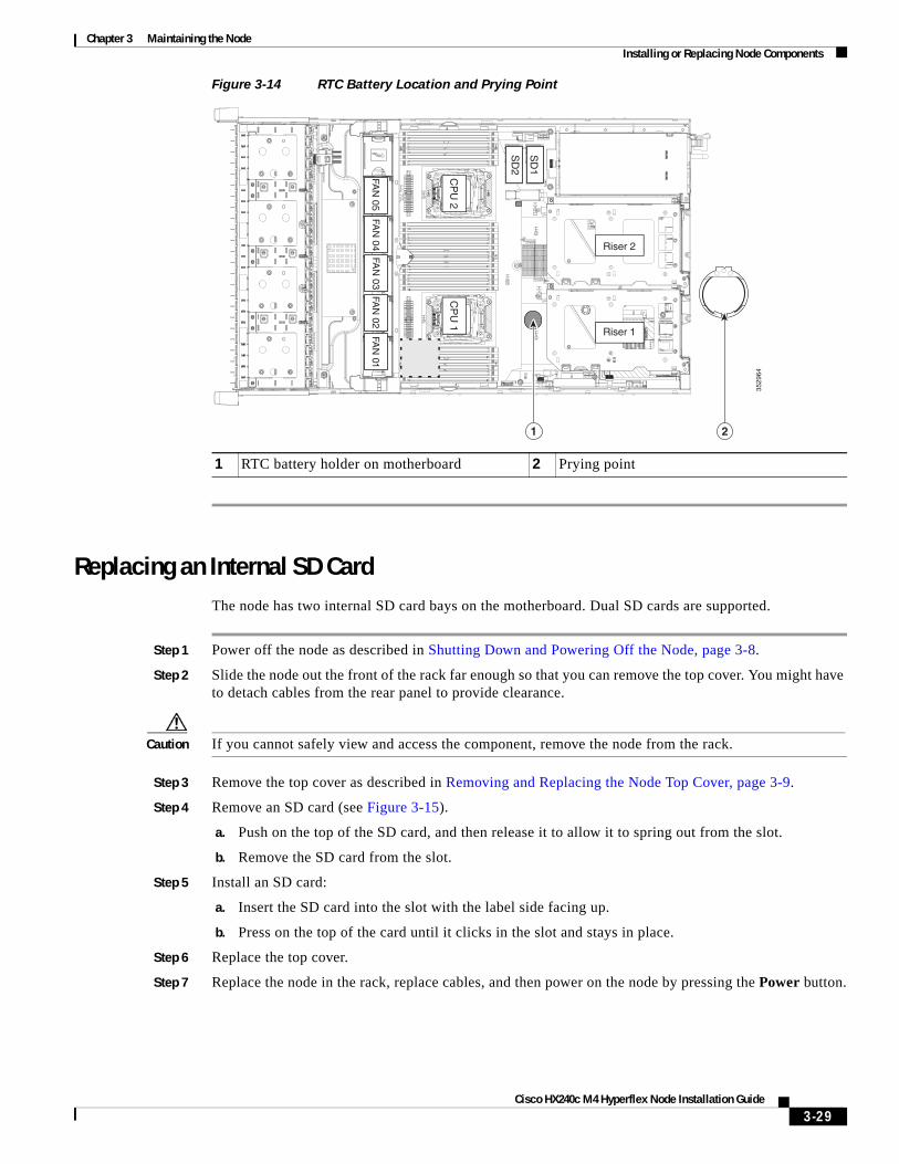
Chapter 3 Maintaining the NodeInstalling or Replacing Node Components
Figure 3-14 RTC Battery Location and Prying Point
Replacing an Internal SD CardThe node has two internal SD card bays on the motherboard. Dual SD cards are supported.
Step 1 Power off the node as described in Shutting Down and Powering Off the Node, page 3-8.
Step 2 Slide the node out the front of the rack far enough so that you can remove the top cover. You might have to detach cables from the rear panel to provide clearance.
Caution If you cannot safely view and access the component, remove the node from the rack.
Step 3 Remove the top cover as described in Removing and Replacing the Node Top Cover, page 3-9.
Step 4 Remove an SD card (see Figure 3-15).
a. Push on the top of the SD card, and then release it to allow it to spring out from the slot.
b. Remove the SD card from the slot.
Step 5 Install an SD card:
a. Insert the SD card into the slot with the label side facing up.
b. Press on the top of the card until it clicks in the slot and stays in place.
Step 6 Replace the top cover.
Step 7 Replace the node in the rack, replace cables, and then power on the node by pressing the Power button.
1 RTC battery holder on motherboard 2 Prying point
3529
64
FAN
05FA
N 04
FAN
03FA
N 02
FAN
01
CP
U 1
CP
U 2
SD
1
SD
2
Riser 2
Riser 1
1 2
3-29Cisco HX240c M4 Hyperflex Node Installation Guide
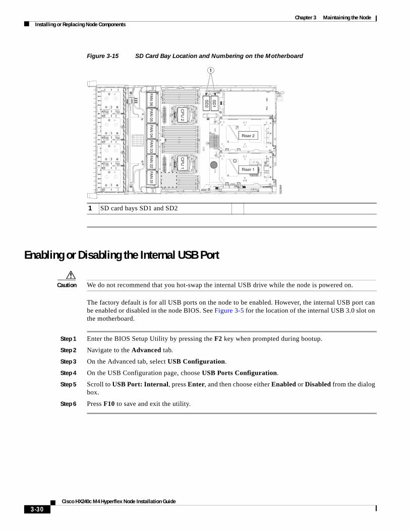
Chapter 3 Maintaining the NodeInstalling or Replacing Node Components
Figure 3-15 SD Card Bay Location and Numbering on the Motherboard
Enabling or Disabling the Internal USB Port
Caution We do not recommend that you hot-swap the internal USB drive while the node is powered on.
The factory default is for all USB ports on the node to be enabled. However, the internal USB port can be enabled or disabled in the node BIOS. See Figure 3-5 for the location of the internal USB 3.0 slot on the motherboard.
Step 1 Enter the BIOS Setup Utility by pressing the F2 key when prompted during bootup.
Step 2 Navigate to the Advanced tab.
Step 3 On the Advanced tab, select USB Configuration.
Step 4 On the USB Configuration page, choose USB Ports Configuration.
Step 5 Scroll to USB Port: Internal, press Enter, and then choose either Enabled or Disabled from the dialog box.
Step 6 Press F10 to save and exit the utility.
1 SD card bays SD1 and SD2
3529
69
FAN
05FA
N 06
FAN
04FA
N 03
FAN
02FA
N 01
CP
U 1
CP
U 2
SD
1
SD
2
Riser 2
Riser 1
1
3-30Cisco HX240c M4 Hyperflex Node Installation Guide
Chapter 3 Maintaining the NodeInstalling or Replacing Node Components
Replacing a PCIe Riser The node contains two toolless PCIe risers for horizontal installation of PCIe cards. See Replacing a PCIe Card, page 3-33 for the specifications of the PCIe slots on the risers.
Step 1 Power off the node as described in Shutting Down and Powering Off the Node, page 3-8.
Step 2 Slide the node out the front of the rack far enough so that you can remove the top cover. You might have to detach cables from the rear panel to provide clearance.
Caution If you cannot safely view and access the component, remove the node from the rack.
Step 3 Remove the top cover as described in Removing and Replacing the Node Top Cover, page 3-9.
Step 4 Remove the PCIe riser that you are replacing (see Figure 3-16):
a. Grasp the top of the riser and lift straight up on both ends to disengage its circuit board from the socket on the motherboard. Set the riser on an antistatic mat.
b. If the riser has a card installed, remove the card from the riser. See Replacing a PCIe Card, page 3-33.
Step 5 Install a new PCIe riser:
a. If you removed a card from the old PCIe riser, install the card to the new riser (see Replacing a PCIe Card, page 3-33).
b. Position the PCIe riser over its socket on the motherboard and over its alignment slots in the chassis (see Figure 3-16). There are also two alignment pegs on the motherboard for each riser.
Note The PCIe risers are not interchangeable. If you plug a PCIe riser into the wrong socket, the node will not boot. Riser 1 must plug into the motherboard socket labeled “RISER1.” Riser 2 must plug into the motherboard socket labeled “RISER2.”
c. Carefully push down on both ends of the PCIe riser to fully engage its circuit board connector with the socket on the motherboard.
Step 6 Replace the top cover.
Step 7 Replace the node in the rack, replace cables, and then power on the node by pressing the Power button.
3-31Cisco HX240c M4 Hyperflex Node Installation Guide

Chapter 3 Maintaining the NodeInstalling or Replacing Node Components
Figure 3-16 PCIe Riser Alignment Features
1 Alignment peg locations on motherboard (two for each riser)
2 Alignment channel locations on chassis(two for each riser)
3529
70
FAN
05FA
N 06
FAN
04FA
N 03
FAN
02FA
N 01
CP
U 1
CP
U 2
SD
1
SD
2
Riser 2
Riser 1
1
2
3-32Cisco HX240c M4 Hyperflex Node Installation Guide
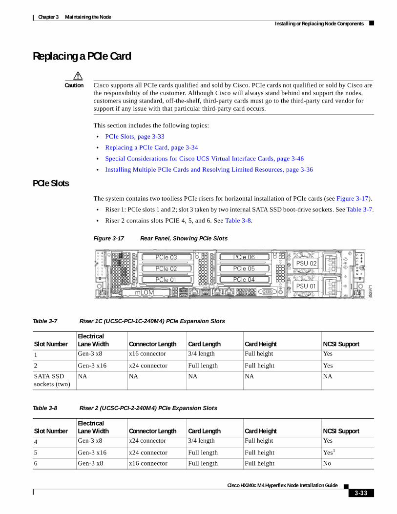
Chapter 3 Maintaining the NodeInstalling or Replacing Node Components
Replacing a PCIe Card
Caution Cisco supports all PCIe cards qualified and sold by Cisco. PCIe cards not qualified or sold by Cisco are the responsibility of the customer. Although Cisco will always stand behind and support the nodes, customers using standard, off-the-shelf, third-party cards must go to the third-party card vendor for support if any issue with that particular third-party card occurs.
This section includes the following topics:
• PCIe Slots, page 3-33
• Replacing a PCIe Card, page 3-34
• Special Considerations for Cisco UCS Virtual Interface Cards, page 3-46
• Installing Multiple PCIe Cards and Resolving Limited Resources, page 3-36
PCIe Slots
The system contains two toolless PCIe risers for horizontal installation of PCIe cards (see Figure 3-17).
• Riser 1: PCIe slots 1 and 2; slot 3 taken by two internal SATA SSD boot-drive sockets. See Table 3-7.
• Riser 2 contains slots PCIE 4, 5, and 6. See Table 3-8.
Figure 3-17 Rear Panel, Showing PCIe Slots
3529
71
PCIe 01
PCIe 03
PCIe 02
mLOM
PCIe 04
PCIe 06
PCIe 05
PSU 01
PSU 02
Table 3-7 Riser 1C (UCSC-PCI-1C-240M4) PCIe Expansion Slots
Slot NumberElectrical Lane Width Connector Length Card Length Card Height NCSI Support
1 Gen-3 x8 x16 connector 3/4 length Full height Yes
2 Gen-3 x16 x24 connector Full length Full height Yes
SATA SSD sockets (two)
NA NA NA NA NA
Table 3-8 Riser 2 (UCSC-PCI-2-240M4) PCIe Expansion Slots
Slot NumberElectrical Lane Width Connector Length Card Length Card Height NCSI Support
4 Gen-3 x8 x24 connector 3/4 length Full height Yes
5 Gen-3 x16 x24 connector Full length Full height Yes1
6 Gen-3 x8 x16 connector Full length Full height No
3-33Cisco HX240c M4 Hyperflex Node Installation Guide
Chapter 3 Maintaining the NodeInstalling or Replacing Node Components
Replacing a PCIe Card
Note If you are installing a Cisco UCS Virtual Interface Card, there are prerequisite considerations. See Special Considerations for Cisco UCS Virtual Interface Cards, page 3-46.
Step 1 Shut down and power off the node as described in Shutting Down and Powering Off the Node, page 3-8.
Step 2 Slide the node out the front of the rack far enough so that you can remove the top cover. You might have to detach cables from the rear panel to provide clearance.
Caution If you cannot safely view and access the component, remove the node from the rack.
Step 3 Remove the top cover as described in Removing and Replacing the Node Top Cover, page 3-9.
Step 4 Remove a PCIe card (or a blanking panel) from the PCIe riser:
a. Lift straight up on both ends of the riser to disengage its circuit board from the socket on the motherboard. Set the riser on an antistatic mat.
b. On the bottom of the riser, loosen the single thumbscrew that holds the securing plate (see Figure 3-18).
c. Swing open the securing plate and remove it from the riser to provide access.
d. Swing open the card-tab retainer that secures the back-panel tab of the card (see Figure 3-18).
e. Pull evenly on both ends of the PCIe card to disengage it from the socket on the PCIe riser (or remove a blanking panel) and then set the card aside.
Step 5 Install a PCIe card:
a. Align the new PCIe card with the empty socket on the PCIe riser.
b. Push down evenly on both ends of the card until it is fully seated in the socket.
Ensure that the card rear panel tab sits flat against the PCIe riser rear panel opening.
c. Close the card-tab retainer (see Figure 3-18).
d. Return the securing plate to the riser. Insert the two hinge-tabs into the two slots on the riser, and then swing the securing plate closed.
e. Tighten the single thumbscrew on the bottom of the securing plate.
f. Position the PCIe riser over its socket on the motherboard and over its alignment features in the chassis (see Figure 3-16).
g. Carefully push down on both ends of the PCIe riser to fully engage its circuit board connector with the socket on the motherboard.
Step 6 Replace the top cover.
Step 7 Replace the node in the rack, replace cables, and then power on the node by pressing the Power button.
1. NCSI is supported in only one slot at a time in this riser version.
3-34Cisco HX240c M4 Hyperflex Node Installation Guide
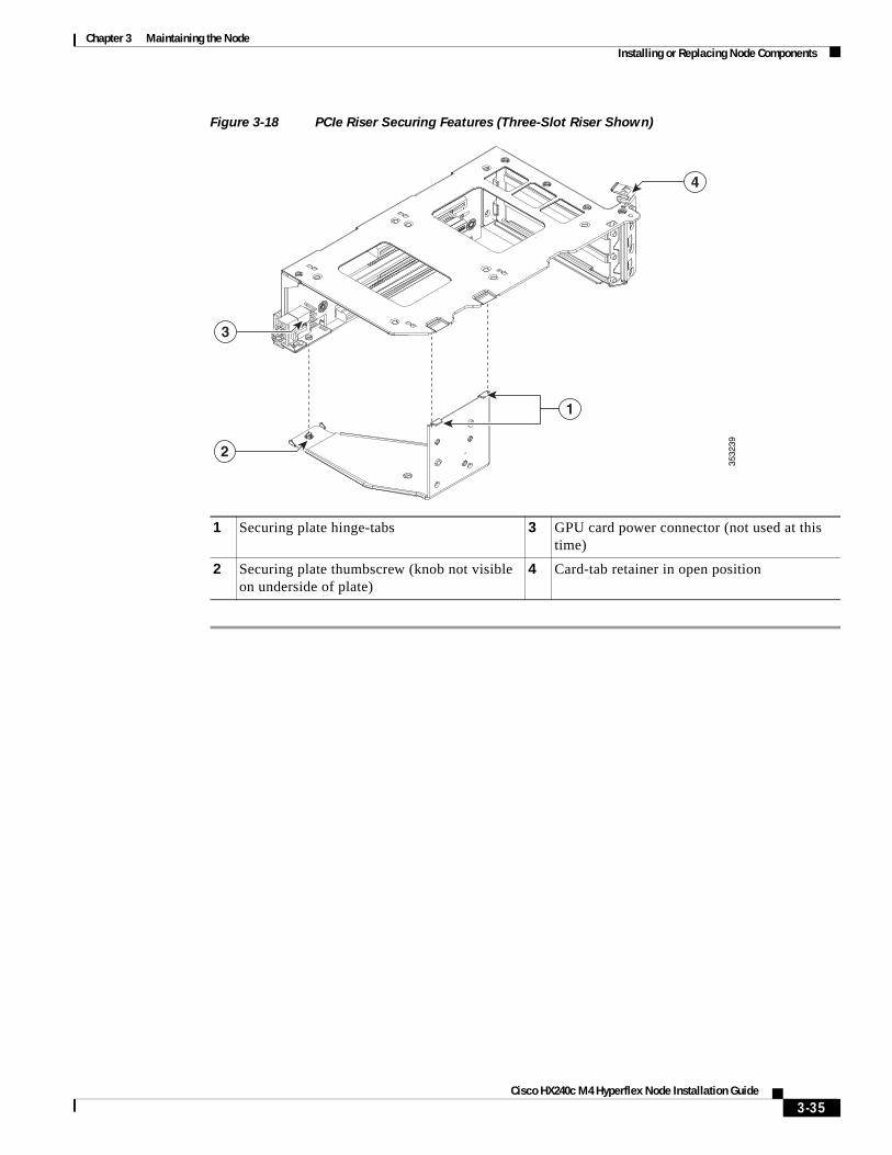
Chapter 3 Maintaining the NodeInstalling or Replacing Node Components
Figure 3-18 PCIe Riser Securing Features (Three-Slot Riser Shown)
1 Securing plate hinge-tabs 3 GPU card power connector (not used at this time)
2 Securing plate thumbscrew (knob not visible on underside of plate)
4 Card-tab retainer in open position
3532
39
4
3
2
1
3-35Cisco HX240c M4 Hyperflex Node Installation Guide
Chapter 3 Maintaining the NodeInstalling or Replacing Node Components
Installing Multiple PCIe Cards and Resolving Limited Resources
When a large number of PCIe add-on cards are installed in the node, the node might run out of the following resources required for PCIe devices:
• Option ROM memory space
• 16-bit I/O space
The topics in this section provide guidelines for resolving the issues related to these limited resources:
• Resolving Insufficient Memory Space to Execute Option ROMs, page 3-36
• Resolving Insufficient 16-Bit I/O Space, page 3-37
Resolving Insufficient Memory Space to Execute Option ROMs
The node has very limited memory to execute PCIe legacy option ROMs, so when a large number of PCIe add-on cards are installed in the node, the node BIOS might not able to execute all of the option ROMs. The node BIOS loads and executes the option ROMs in the order that the PCIe cards are enumerated (slot 1, slot 2, slot 3, and so on).
If the node BIOS does not have sufficient memory space to load any PCIe option ROM, it skips loading that option ROM, reports a system event log (SEL) event to the Cisco IMC controller and reports the following error in the Error Manager page of the BIOS Setup utility:
ERROR CODE SEVERITY INSTANCE DESCRIPTION146 Major N/A PCI out of resources error.
Major severity requires userintervention but does notprevent system boot.
To resolve this issue, disable the Option ROMs that are not needed for node booting. The BIOS Setup Utility provides the setup options to enable or disable the Option ROMs at the PCIe slot level for the PCIe expansion slots and at the port level for the onboard NICs. These options can be found in the BIOS Setup Utility Advanced PCI Configuration page.
• Guidelines for RAID controller booting
If the node is configured to boot primarily from RAID storage, make sure that the option ROMs for the slots where your RAID controllers installed are enabled in the BIOS, depending on your RAID controller configuration.
If the RAID controller does not appear in the node boot order even with the option ROMs for those slots are enabled, the RAID controller option ROM might not have sufficient memory space to execute. In that case, disable other option ROMs that are not needed for the node configuration to free up some memory space for the RAID controller option ROM.
• Guidelines for onboard NIC PXE booting
If the node is configured to primarily perform PXE boot from onboard NICs, make sure that the option ROMs for the onboard NICs to be booted from are enabled in the BIOS Setup Utility. Disable other option ROMs that are not needed to create sufficient memory space for the onboard NICs.
3-36Cisco HX240c M4 Hyperflex Node Installation Guide
Chapter 3 Maintaining the NodeInstalling or Replacing Node Components
Resolving Insufficient 16-Bit I/O Space
The node has only 64 KB of legacy 16-bit I/O resources available. This 64 KB of I/O space is divided between the CPUs in the node because the PCIe controller is integrated into the CPUs. This node BIOS has the capability to dynamically detect the 16-bit I/O resource requirement for each CPU and then balance the 16-bit I/O resource allocation between the CPUs during the PCI bus enumeration phase of the BIOS POST.
When a large number of PCIe cards are installed in the node, the node BIOS might not have sufficient I/O space for some PCIe devices. If the node BIOS is not able to allocate the required I/O resources for any PCIe devices, the following symptoms have been observed:
• The node might get stuck in an infinite reset loop.
• The BIOS might appear to hang while initializing PCIe devices.
• The PCIe option ROMs might take excessive time to complete, which appears to lock up the node.
• PCIe boot devices might not be accessible from the BIOS.
• PCIe option ROMs might report initialization errors. These errors are seen before the BIOS passes control to the operating system.
• The keyboard might not work.
To work around this problem, rebalance the 16-bit I/O load using the following methods:
1. Physically remove any unused PCIe cards.
2. If the node has one or more Cisco virtual interface cards (VICs) installed, disable the PXE boot on the VICs that are not required for the node boot configuration by using the Network Adapters page in Cisco IMC Web UI to free up some 16-bit I/O resources. Each VIC uses a minimum 16 KB of 16-bit I/O resource, so disabling PXE boot on Cisco VICs would free up some 16-bit I/O resources that can be used for other PCIe cards that are installed in the node.
3-37Cisco HX240c M4 Hyperflex Node Installation Guide
Chapter 3 Maintaining the NodeInstalling or Replacing Node Components
Replacing the Internal Housekeeping SSDs for SDS Logs PCIe riser 1 includes sockets for two 120 GB SATA SSDs.
Note This procedure requires assistance from technical support for additional software update steps after the hardware is replaced.
Step 1 Shut down and power off the node as described in Shutting Down and Powering Off the Node, page 3-8.
Step 2 Slide the node out the front of the rack far enough so that you can remove the top cover. You might have to detach cables from the rear panel to provide clearance.
Step 3 Remove the top cover as described in Removing and Replacing the Node Top Cover, page 3-9.
Step 4 Remove PCIe riser 1 from the node:
a. Lift straight up on both ends of the riser to disengage its circuit board from the socket on the motherboard. Set the riser on an antistatic mat.
b. On the bottom of the riser, loosen the single thumbscrew that holds the securing plate. See Figure 3-18.
c. Swing open the securing plate and remove it from the riser to provide access.
Step 5 Remove an existing SSD from PCIe riser 1.
Grasp the carrier-tabs on each side of the SSD and pinch them together as you pull the SSD from its cage and the socket on the PCIe riser.
Step 6 Install a new SSD to PCIe riser 1.:
a. Grasp the two carrier-tabs on either side of the SSD and pinch them together as you insert the SSD into the cage on the riser.
b. Push the SSD straight into the cage to engage it with the socket on the riser. Stop when the carrier-tabs click and lock into place on the cage.
Step 7 Return PCIe riser 1 to the node:
a. Return the securing plate to the riser. Insert the two hinge-tabs into the two slots on the riser, and then swing the securing plate closed.
b. Tighten the single thumbscrew that holds the securing plate.
c. Position the PCIe riser over its socket on the motherboard and over its alignment features in the chassis (see Figure 3-16).
d. Carefully push down on both ends of the PCIe riser to fully engage its circuit board connector with the socket on the motherboard.
Step 8 Replace the top cover.
Step 9 Replace the node in the rack, replace cables, and then power on the node by pressing the Power button.
Step 10 Set the boot order for this SSD in the node BIOS as desired:
a. Boot the system and press F2 when prompted to enter the BIOS Setup Utility.
b. Select the Boot Options tab.
c. Set the boot order for your SATA boot drives.
d. Press F10 to exit the utility and save your changes.
Note After you replace the SSD hardware, you must contact technical support for additional software update steps.
3-38Cisco HX240c M4 Hyperflex Node Installation Guide
Chapter 3 Maintaining the NodeInstalling or Replacing Node Components
Installing a Trusted Platform Module The trusted platform module (TPM) is a small circuit board that connects to a motherboard socket and is secured by a one-way screw. The socket location is on the motherboard under PCIe riser 2.
This section contains the following procedures, which must be followed in this order when installing and enabling a TPM:
1. Installing the TPM Hardware, page 3-39
2. Enabling TPM Support in the BIOS, page 3-40
3. Enabling the Intel TXT Feature in the BIOS, page 3-41
Installing the TPM Hardware
Step 1 Prepare the node for component installation:
Step 2 Power off the node as described in Shutting Down and Powering Off the Node, page 3-8.
Step 3 Slide the node out the front of the rack far enough so that you can remove the top cover. You might have to detach cables from the rear panel to provide clearance.
Caution If you cannot safely view and access the component, remove the node from the rack.
Step 4 Remove the top cover as described in Removing and Replacing the Node Top Cover, page 3-9.
Step 5 Remove PCIe riser 2 to provide clearance. See Replacing a PCIe Riser, page 3-31 for instructions.
Step 6 Install a TPM:
a. Locate the TPM socket on the motherboard, as shown in Figure 3-19.
b. Align the connector that is on the bottom of the TPM circuit board with the motherboard TPM socket. Align the screw hole and standoff on the TPM board with the screw hole that is adjacent to the TPM socket.
c. Push down evenly on the TPM to seat it in the motherboard socket.
d. Install the single one-way screw that secures the TPM to the motherboard.
Step 7 Replace PCIe riser 2 to the node. See Replacing a PCIe Riser, page 3-31 for instructions.
Step 8 Replace the top cover.
Step 9 Replace the node in the rack, replace cables, and then power on the node by pressing the Power button.
Step 10 Continue with Enabling TPM Support in the BIOS, page 3-40.
3-39Cisco HX240c M4 Hyperflex Node Installation Guide
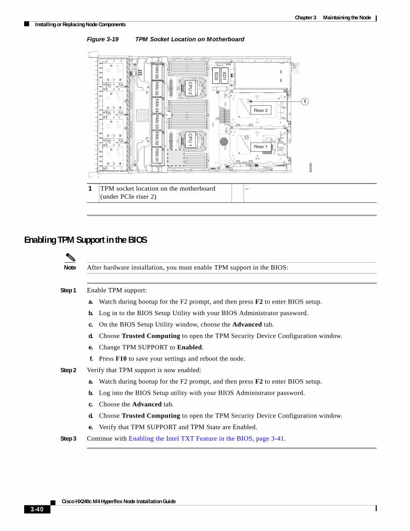
Chapter 3 Maintaining the NodeInstalling or Replacing Node Components
Cisco HX240c M4 Hyperflex Node Installation Guide
Figure 3-19 TPM Socket Location on Motherboard
Enabling TPM Support in the BIOS
Note After hardware installation, you must enable TPM support in the BIOS:
Step 1 Enable TPM support:
a. Watch during bootup for the F2 prompt, and then press F2 to enter BIOS setup.
b. Log in to the BIOS Setup Utility with your BIOS Administrator password.
c. On the BIOS Setup Utility window, choose the Advanced tab.
d. Choose Trusted Computing to open the TPM Security Device Configuration window.
e. Change TPM SUPPORT to Enabled.
f. Press F10 to save your settings and reboot the node.
Step 2 Verify that TPM support is now enabled:
a. Watch during bootup for the F2 prompt, and then press F2 to enter BIOS setup.
b. Log into the BIOS Setup utility with your BIOS Administrator password.
c. Choose the Advanced tab.
d. Choose Trusted Computing to open the TPM Security Device Configuration window.
e. Verify that TPM SUPPORT and TPM State are Enabled.
Step 3 Continue with Enabling the Intel TXT Feature in the BIOS, page 3-41.
1 TPM socket location on the motherboard (under PCIe riser 2)
–
3529
65
FAN
05FA
N 06
FAN
04FA
N 03
FAN
02FA
N 01
CP
U 1
CP
U 2
SD
1
SD
2
Riser 2
Riser 1
1
3-40
Chapter 3 Maintaining the NodeInstalling or Replacing Node Components
Enabling the Intel TXT Feature in the BIOS
Intel Trusted Execution Technology (TXT) provides greater protection for information that is used and stored on the node. A key aspect of that protection is the provision of an isolated execution environment and associated sections of memory where operations can be conducted on sensitive data, invisibly to the rest of the node. Intel TXT provides for a sealed portion of storage where sensitive data such as encryption keys can be kept, helping to shield them from being compromised during an attack by malicious code.
Step 1 Reboot the node and watch for the prompt to press F2.
Step 2 When prompted, press F2 to enter the BIOS Setup utility.
Step 3 Verify that the prerequisite BIOS values are enabled:
a. Choose the Advanced tab.
b. Choose Intel TXT(LT-SX) Configuration to open the Intel TXT(LT-SX) Hardware Support window.
c. Verify that the following items are listed as Enabled:
– VT-d Support (default is Enabled)
– VT Support (default is Enabled)
– TPM Support
– TPM State
• If VT-d Support and VT Support are already enabled, skip to Step 4.
• If VT-d Support and VT Support are not enabled, continue with the next steps to enable them.
d. Press Escape to return to the BIOS Setup utility Advanced tab.
e. On the Advanced tab, choose Processor Configuration to open the Processor Configuration window.
f. Set Intel (R) VT and Intel (R) VT-d to Enabled.
Step 4 Enable the Intel Trusted Execution Technology (TXT) feature:
a. Return to the Intel TXT(LT-SX) Hardware Support window if you are not already there.
b. Set TXT Support to Enabled.
Step 5 Press F10 to save your changes and exit the BIOS Setup utility.
3-41Cisco HX240c M4 Hyperflex Node Installation Guide
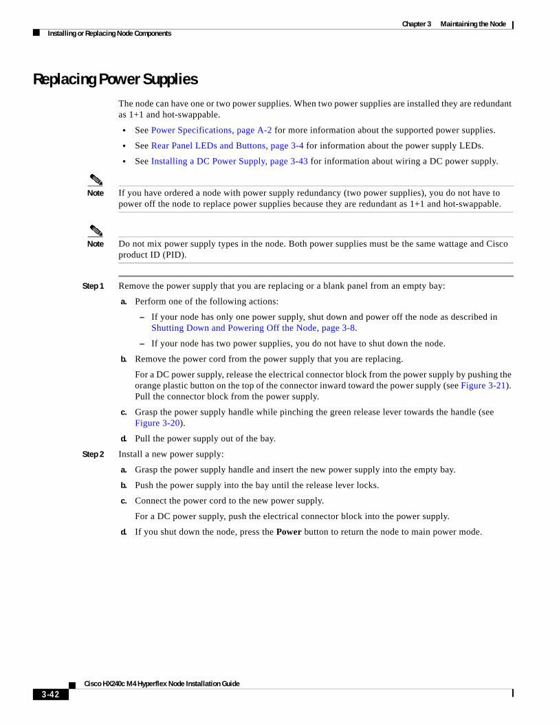
Chapter 3 Maintaining the NodeInstalling or Replacing Node Components
Replacing Power Supplies The node can have one or two power supplies. When two power supplies are installed they are redundant as 1+1 and hot-swappable.
• See Power Specifications, page A-2 for more information about the supported power supplies.
• See Rear Panel LEDs and Buttons, page 3-4 for information about the power supply LEDs.
• See Installing a DC Power Supply, page 3-43 for information about wiring a DC power supply.
Note If you have ordered a node with power supply redundancy (two power supplies), you do not have to power off the node to replace power supplies because they are redundant as 1+1 and hot-swappable.
Note Do not mix power supply types in the node. Both power supplies must be the same wattage and Cisco product ID (PID).
Step 1 Remove the power supply that you are replacing or a blank panel from an empty bay:
a. Perform one of the following actions:
– If your node has only one power supply, shut down and power off the node as described in Shutting Down and Powering Off the Node, page 3-8.
– If your node has two power supplies, you do not have to shut down the node.
b. Remove the power cord from the power supply that you are replacing.
For a DC power supply, release the electrical connector block from the power supply by pushing the orange plastic button on the top of the connector inward toward the power supply (see Figure 3-21). Pull the connector block from the power supply.
c. Grasp the power supply handle while pinching the green release lever towards the handle (see Figure 3-20).
d. Pull the power supply out of the bay.
Step 2 Install a new power supply:
a. Grasp the power supply handle and insert the new power supply into the empty bay.
b. Push the power supply into the bay until the release lever locks.
c. Connect the power cord to the new power supply.
For a DC power supply, push the electrical connector block into the power supply.
d. If you shut down the node, press the Power button to return the node to main power mode.
3-42Cisco HX240c M4 Hyperflex Node Installation Guide
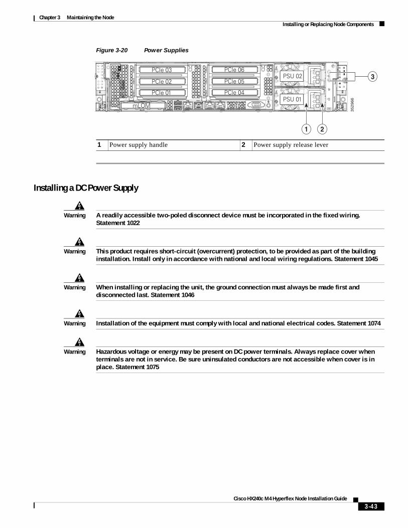
Chapter 3 Maintaining the NodeInstalling or Replacing Node Components
Figure 3-20 Power Supplies
Installing a DC Power Supply
Warning A readily accessible two-poled disconnect device must be incorporated in the fixed wiring. Statement 1022
Warning This product requires short-circuit (overcurrent) protection, to be provided as part of the building installation. Install only in accordance with national and local wiring regulations. Statement 1045
Warning When installing or replacing the unit, the ground connection must always be made first and disconnected last. Statement 1046
Warning Installation of the equipment must comply with local and national electrical codes. Statement 1074
Warning Hazardous voltage or energy may be present on DC power terminals. Always replace cover when terminals are not in service. Be sure uninsulated conductors are not accessible when cover is in place. Statement 1075
1 Power supply handle 2 Power supply release lever
352966
PCIe 01
PCIe 03
PCIe 02
mLOM
PCIe 04
PCIe 06
PCIe 05
PSU 01
PSU 02
1 2
3
3-43Cisco HX240c M4 Hyperflex Node Installation Guide
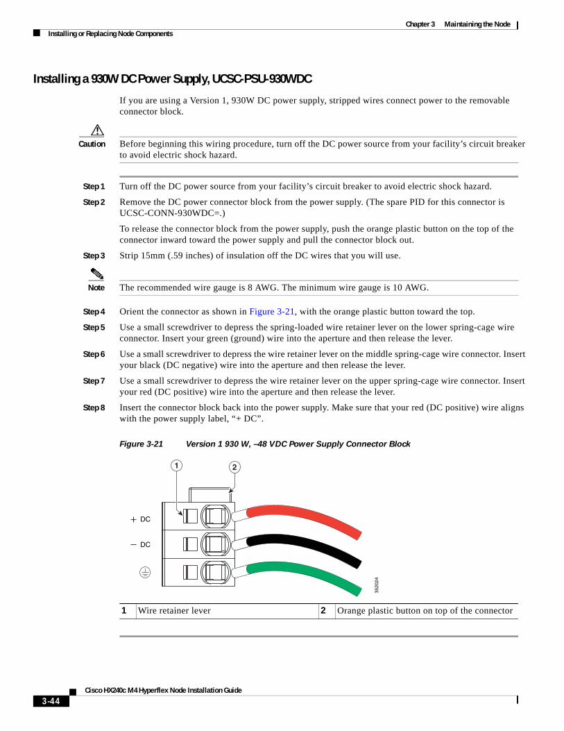
Chapter 3 Maintaining the NodeInstalling or Replacing Node Components
Installing a 930W DC Power Supply, UCSC-PSU-930WDC
If you are using a Version 1, 930W DC power supply, stripped wires connect power to the removable connector block.
Caution Before beginning this wiring procedure, turn off the DC power source from your facility’s circuit breaker to avoid electric shock hazard.
Step 1 Turn off the DC power source from your facility’s circuit breaker to avoid electric shock hazard.
Step 2 Remove the DC power connector block from the power supply. (The spare PID for this connector is UCSC-CONN-930WDC=.)
To release the connector block from the power supply, push the orange plastic button on the top of the connector inward toward the power supply and pull the connector block out.
Step 3 Strip 15mm (.59 inches) of insulation off the DC wires that you will use.
Note The recommended wire gauge is 8 AWG. The minimum wire gauge is 10 AWG.
Step 4 Orient the connector as shown in Figure 3-21, with the orange plastic button toward the top.
Step 5 Use a small screwdriver to depress the spring-loaded wire retainer lever on the lower spring-cage wire connector. Insert your green (ground) wire into the aperture and then release the lever.
Step 6 Use a small screwdriver to depress the wire retainer lever on the middle spring-cage wire connector. Insert your black (DC negative) wire into the aperture and then release the lever.
Step 7 Use a small screwdriver to depress the wire retainer lever on the upper spring-cage wire connector. Insert your red (DC positive) wire into the aperture and then release the lever.
Step 8 Insert the connector block back into the power supply. Make sure that your red (DC positive) wire aligns with the power supply label, “+ DC”.
Figure 3-21 Version 1 930 W, –48 VDC Power Supply Connector Block
1 Wire retainer lever 2 Orange plastic button on top of the connector
DC
DC
21
3520
24
3-44Cisco HX240c M4 Hyperflex Node Installation Guide
Chapter 3 Maintaining the NodeInstalling or Replacing Node Components
Replacing an mLOM Card (Cisco VIC 1227)The node uses a Cisco VIC 1227 mLOM adapter. The mLOM card socket remains powered when the node is in 12 V standby power mode and it supports the network communications services (NCSI) protocol.
• Replacing an mLOM Card, page 3-45
• Special Considerations for Cisco UCS Virtual Interface Cards, page 3-46
Replacing an mLOM Card
Step 1 Power off the node as described in Shutting Down and Powering Off the Node, page 3-8.
Step 2 Slide the node out the front of the rack far enough so that you can remove the top cover. You might have to detach cables from the rear panel to provide clearance.
Caution If you cannot safely view and access the component, remove the node from the rack.
Step 3 Remove the top cover as described in Removing and Replacing the Node Top Cover, page 3-9.
Step 4 Remove PCIe riser 1 to provide clearance. See Replacing a PCIe Riser, page 3-31 for instructions.
Step 5 Remove any existing mLOM card or a blanking panel (see Figure 3-22):
a. Loosen the single thumbscrew that secures the mLOM card to the chassis floor.
b. Slide the mLOM card horizontally to disengage its connector from the motherboard socket.
Step 6 Install a new mLOM card:
a. Set the mLOM card on the chassis floor so that its connector is aligned with the motherboard socket and its thumbscrew is aligned with the standoff on the chassis floor.
b. Push the card’s connector into the motherboard socket horizontally.
c. Tighten the thumbscrew to secure the card to the chassis floor.
Step 7 Return PCIe riser 1 to the node. See Replacing a PCIe Riser, page 3-31 for instructions.
Step 8 Replace the top cover.
Step 9 Replace the node in the rack, replace cables, and then power on the node by pressing the Power button.
3-45Cisco HX240c M4 Hyperflex Node Installation Guide
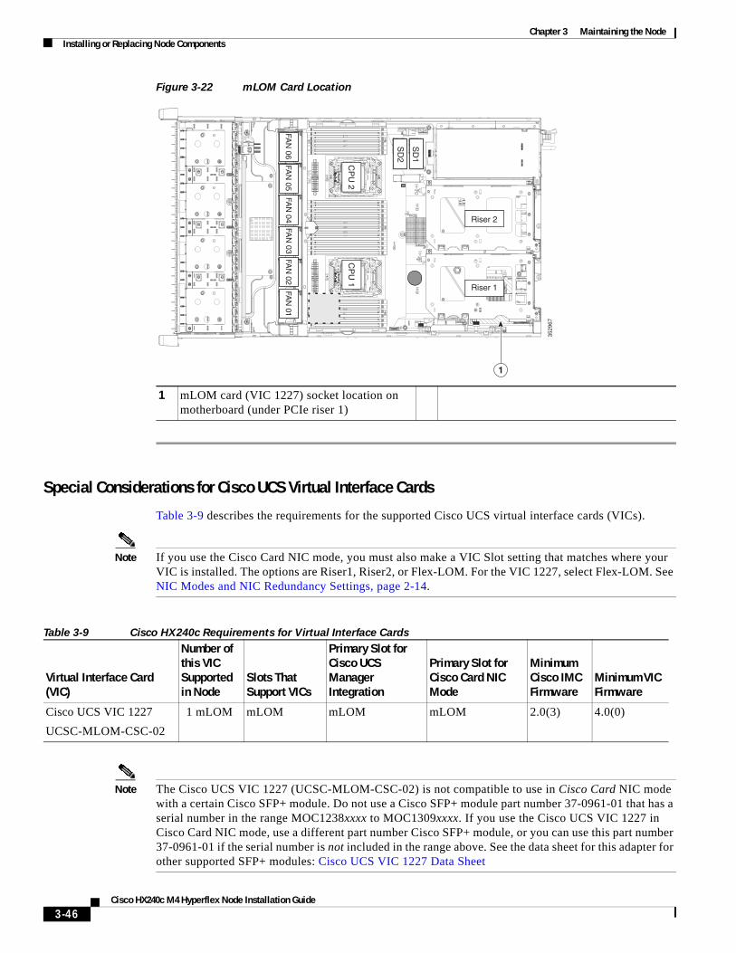
Chapter 3 Maintaining the NodeInstalling or Replacing Node Components
Figure 3-22 mLOM Card Location
Special Considerations for Cisco UCS Virtual Interface Cards
Table 3-9 describes the requirements for the supported Cisco UCS virtual interface cards (VICs).
Note If you use the Cisco Card NIC mode, you must also make a VIC Slot setting that matches where your VIC is installed. The options are Riser1, Riser2, or Flex-LOM. For the VIC 1227, select Flex-LOM. See NIC Modes and NIC Redundancy Settings, page 2-14.
Note The Cisco UCS VIC 1227 (UCSC-MLOM-CSC-02) is not compatible to use in Cisco Card NIC mode with a certain Cisco SFP+ module. Do not use a Cisco SFP+ module part number 37-0961-01 that has a serial number in the range MOC1238xxxx to MOC1309xxxx. If you use the Cisco UCS VIC 1227 in Cisco Card NIC mode, use a different part number Cisco SFP+ module, or you can use this part number 37-0961-01 if the serial number is not included in the range above. See the data sheet for this adapter for other supported SFP+ modules: Cisco UCS VIC 1227 Data Sheet
1 mLOM card (VIC 1227) socket location on motherboard (under PCIe riser 1)
3529
67
FAN
05FA
N 06
FAN
04FA
N 03
FAN
02FA
N 01
CP
U 1
CP
U 2
SD
1
SD
2
Riser 2
Riser 1
1
Table 3-9 Cisco HX240c Requirements for Virtual Interface Cards
Virtual Interface Card (VIC)
Number of this VIC Supported in Node
Slots That Support VICs
Primary Slot for Cisco UCS Manager Integration
Primary Slot for Cisco Card NIC Mode
Minimum Cisco IMC Firmware
Minimum VIC Firmware
Cisco UCS VIC 1227
UCSC-MLOM-CSC-02
1 mLOM mLOM mLOM mLOM 2.0(3) 4.0(0)
3-46Cisco HX240c M4 Hyperflex Node Installation Guide
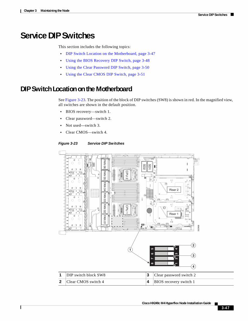
Chapter 3 Maintaining the NodeService DIP Switches
Service DIP SwitchesThis section includes the following topics:
• DIP Switch Location on the Motherboard, page 3-47
• Using the BIOS Recovery DIP Switch, page 3-48
• Using the Clear Password DIP Switch, page 3-50
• Using the Clear CMOS DIP Switch, page 3-51
DIP Switch Location on the MotherboardSee Figure 3-23. The position of the block of DIP switches (SW8) is shown in red. In the magnified view, all switches are shown in the default position.
• BIOS recovery—switch 1.
• Clear password—switch 2.
• Not used—switch 3.
• Clear CMOS—switch 4.
Figure 3-23 Service DIP Switches
1 DIP switch block SW8 3 Clear password switch 2
2 Clear CMOS switch 4 4 BIOS recovery switch 1
3529
68
FAN
05FA
N 06
FAN
04FA
N 03
FAN
02FA
N 01
CP
U 1
CP
U 2
SD
1
SD
2
Riser 2
Riser 1
1
12
34
87
65
3
4
2
3-47Cisco HX240c M4 Hyperflex Node Installation Guide
Chapter 3 Maintaining the NodeService DIP Switches
Using the BIOS Recovery DIP SwitchDepending on which stage the BIOS becomes corrupted, you might see different behavior.
• If the BIOS BootBlock is corrupted, you might see the node get stuck on the following message:
Initializing and configuring memory/hardware
• If it is a non-BootBlock corruption, the following message is displayed:
****BIOS FLASH IMAGE CORRUPTED****Flash a valid BIOS capsule file using Cisco IMC WebGUI or CLI interface.IF Cisco IMC INTERFACE IS NOT AVAILABLE, FOLLOW THE STEPS MENTIONED BELOW.1. Connect the USB stick with recovery.cap file in root folder.2. Reset the host.IF THESE STEPS DO NOT RECOVER THE BIOS1. Power off the system.2. Mount recovery jumper.3. Connect the USB stick with recovery.cap file in root folder.4. Power on the system.Wait for a few seconds if already plugged in the USB stick.REFER TO SYSTEM MANUAL FOR ANY ISSUES.
Note As indicated by the message shown above, there are two procedures for recovering the BIOS. Try procedure 1 first. If that procedure does not recover the BIOS, use procedure 2.
Procedure 1: Reboot with recovery.cap File
Step 1 Download the BIOS update package and extract it to a temporary location.
Step 2 Copy the contents of the extracted recovery folder to the root directory of a USB thumb drive. The recovery folder contains the recovery.cap file that is required in this procedure.
Note The recovery.cap file must be in the root directory of the USB thumb drive. Do not rename this file. The USB thumb drive must be formatted with either FAT16 or FAT32 file systems.
Step 3 Insert the USB thumb drive into a USB port on the node.
Step 4 Reboot the node.
Step 5 Return the node to main power mode by pressing the Power button on the front panel.
The node boots with the updated BIOS boot block. When the BIOS detects a valid recovery.cap file on the USB thumb drive, it displays this message:
Found a valid recovery file...Transferring to Cisco IMCSystem would flash the BIOS image now...System would restart with recovered image after a few seconds...
Step 6 Wait for node to complete the BIOS update, and then remove the USB thumb drive from the node.
Note During the BIOS update, Cisco IMC shuts down the node and the screen goes blank for about 10 minutes. Do not unplug the power cords during this update. Cisco IMC powers on the node after the update is complete.
3-48Cisco HX240c M4 Hyperflex Node Installation Guide
Chapter 3 Maintaining the NodeService DIP Switches
Procedure 2: Use BIOS Recovery DIP switch and recovery.cap File
See Figure 3-23 for the location of the SW8 block of DIP switches.
Step 1 Download the BIOS update package and extract it to a temporary location.
Step 2 Copy the contents of the extracted recovery folder to the root directory of a USB thumb drive. The recovery folder contains the recovery.cap file that is required in this procedure.
Note The recovery.cap file must be in the root directory of the USB thumb drive. Do not rename this file. The USB thumb drive must be formatted with either FAT16 or FAT32 file systems.
Step 3 Power off the node as described in Shutting Down and Powering Off the Node, page 3-8.
Step 4 Disconnect all power cords from the power supplies.
Step 5 Slide the node out the front of the rack far enough so that you can remove the top cover. You might have to detach cables from the rear panel to provide clearance.
Caution If you cannot safely view and access the component, remove the node from the rack.
Step 6 Remove the top cover as described in Removing and Replacing the Node Top Cover, page 3-9.
Step 7 Slide the BIOS recovery DIP switch from position 1 to the closed position (see Figure 3-23).
Step 8 Reconnect AC power cords to the node. The node powers up to standby power mode.
Step 9 Insert the USB thumb drive that you prepared in Step 2 into a USB port on the node.
Step 10 Return the node to main power mode by pressing the Power button on the front panel.
The node boots with the updated BIOS boot block. When the BIOS detects a valid recovery.cap file on the USB thumb drive, it displays this message:
Found a valid recovery file...Transferring to Cisco IMCSystem would flash the BIOS image now...System would restart with recovered image after a few seconds...
Step 11 Wait for node to complete the BIOS update, and then remove the USB thumb drive from the node.
Note During the BIOS update, Cisco IMC shuts down the node and the screen goes blank for about 10 minutes. Do not unplug the power cords during this update. Cisco IMC powers on the node after the update is complete.
Step 12 After the node has fully booted, power off the node again and disconnect all power cords.
Step 13 Slide the BIOS recovery DIP switch from the closed position back to the default position 1.
Note If you do not move the jumper, after recovery completion you see the prompt, “Please remove the recovery jumper.”
Step 14 Replace the top cover, replace the node in the rack, replace power cords and any other cables, and then power on the node by pressing the Power button.
3-49Cisco HX240c M4 Hyperflex Node Installation Guide
Chapter 3 Maintaining the NodeService DIP Switches
Using the Clear Password DIP SwitchSee Figure 3-23 for the location of this DIP switch. You can use this switch to clear the administrator password.
Step 1 Power off the node as described in Shutting Down and Powering Off the Node, page 3-8.
Step 2 Disconnect all power cords from the power supplies.
Step 3 Slide the node out the front of the rack far enough so that you can remove the top cover. You might have to detach cables from the rear panel to provide clearance.
Caution If you cannot safely view and access the component, remove the node from the rack.
Step 4 Remove the top cover as described in Removing and Replacing the Node Top Cover, page 3-9.
Step 5 Slide the clear password DIP switch from position 2 to the closed position (see Figure 3-23).
Step 6 Reinstall the top cover and reconnect AC power cords to the node. The node powers up to standby power mode, indicated when the Power LED on the front panel is amber.
Step 7 Return the node to main power mode by pressing the Power button on the front panel. The node is in main power mode when the Power LED is green.
Note You must allow the entire node, not just the service processor, to reboot to main power mode to complete the reset. The state of the jumper cannot be determined without the host CPU running.
Step 8 Press the Power button to shut down the node to standby power mode, and then remove AC power cords from the node to remove all power.
Step 9 Remove the top cover from the node.
Step 10 Slide the clear CMOS DIP switch from the closed position back to default position 2 (see Figure 3-23).
Note If you do not move the jumper, the CMOS settings are reset to the default every time that you power-cycle the node.
Step 11 Replace the top cover, replace the node in the rack, replace power cords and any other cables, and then power on the node by pressing the Power button.
3-50Cisco HX240c M4 Hyperflex Node Installation Guide
Chapter 3 Maintaining the NodeService DIP Switches
Using the Clear CMOS DIP SwitchSee Figure 3-23 for the location of this DIP switch. You can use this switch to clear the node’s CMOS settings in the case of a system hang. For example, if the node hangs because of incorrect settings and does not boot, use this jumper to invalidate the settings and reboot with defaults.
Caution Clearing the CMOS removes any customized settings and might result in data loss. Make a note of any necessary customized settings in the BIOS before you use this clear CMOS procedure.
Step 1 Power off the node as described in Shutting Down and Powering Off the Node, page 3-8.
Step 2 Disconnect all power cords from the power supplies.
Step 3 Slide the node out the front of the rack far enough so that you can remove the top cover. You might have to detach cables from the rear panel to provide clearance.
Caution If you cannot safely view and access the component, remove the node from the rack.
Step 4 Remove the top cover as described in Removing and Replacing the Node Top Cover, page 3-9.
Step 5 Slide the clear CMOS DIP switch from position 4 to the closed position (see Figure 3-23).
Step 6 Reinstall the top cover and reconnect AC power cords to the node. The node powers up to standby power mode, indicated when the Power LED on the front panel is amber.
Step 7 Return the node to main power mode by pressing the Power button on the front panel. The node is in main power mode when the Power LED is green.
Note You must allow the entire node, not just the service processor, to reboot to main power mode to complete the reset. The state of the jumper cannot be determined without the host CPU running.
Step 8 Press the Power button to shut down the node to standby power mode, and then remove AC power cords from the node to remove all power.
Step 9 Remove the top cover from the node.
Step 10 Move the clear CMOS DIP switch from the closed position back to default position 4 (see Figure 3-23).
Note If you do not move the jumper, the CMOS settings are reset to the default every time that you power-cycle the node.
Step 11 Replace the top cover, replace the node in the rack, replace power cords and any other cables, and then power on the node by pressing the Power button.
3-51Cisco HX240c M4 Hyperflex Node Installation Guide

Chapter 3 Maintaining the NodeService DIP Switches
3-52Cisco HX240c M4 Hyperflex Node Installation Guide
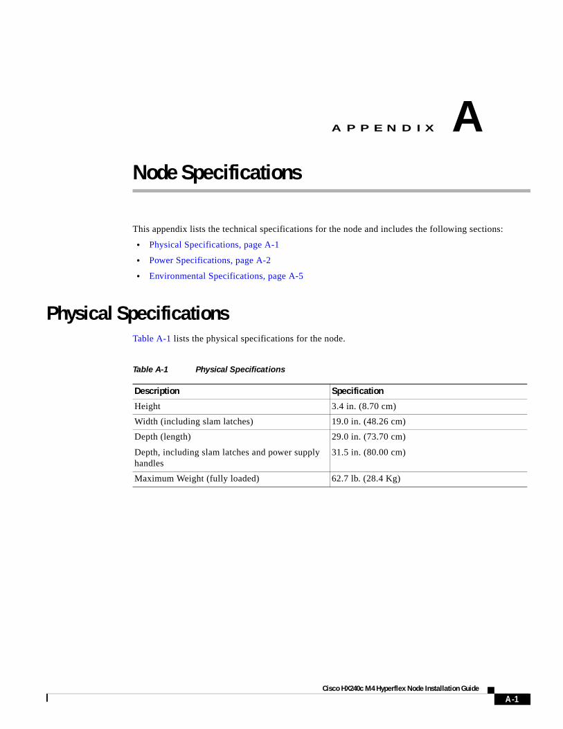
Cisco H
A
P P E N D I X A
Node SpecificationsThis appendix lists the technical specifications for the node and includes the following sections:
• Physical Specifications, page A-1
• Power Specifications, page A-2
• Environmental Specifications, page A-5
Physical SpecificationsTable A-1 lists the physical specifications for the node.
Table A-1 Physical Specifications
Description Specification
Height 3.4 in. (8.70 cm)
Width (including slam latches) 19.0 in. (48.26 cm)
Depth (length)
Depth, including slam latches and power supply handles
29.0 in. (73.70 cm)
31.5 in. (80.00 cm)
Maximum Weight (fully loaded) 62.7 lb. (28.4 Kg)
A-1X240c M4 Hyperflex Node Installation Guide
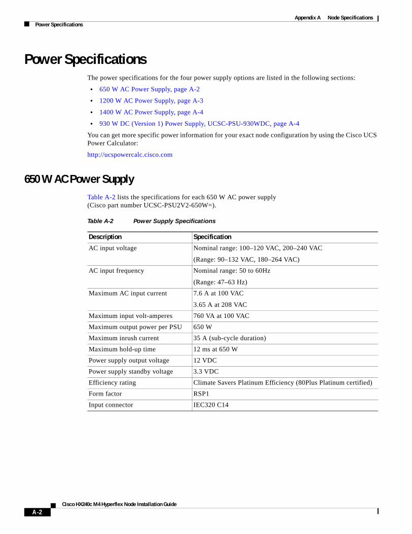
Appendix A Node SpecificationsPower Specifications
Power Specifications The power specifications for the four power supply options are listed in the following sections:
• 650 W AC Power Supply, page A-2
• 1200 W AC Power Supply, page A-3
• 1400 W AC Power Supply, page A-4
• 930 W DC (Version 1) Power Supply, UCSC-PSU-930WDC, page A-4
You can get more specific power information for your exact node configuration by using the Cisco UCS Power Calculator:
http://ucspowercalc.cisco.com
650 W AC Power SupplyTable A-2 lists the specifications for each 650 W AC power supply (Cisco part number UCSC-PSU2V2-650W=).
Table A-2 Power Supply Specifications
Description Specification
AC input voltage Nominal range: 100–120 VAC, 200–240 VAC
(Range: 90–132 VAC, 180–264 VAC)
AC input frequency Nominal range: 50 to 60Hz
(Range: 47–63 Hz)
Maximum AC input current 7.6 A at 100 VAC
3.65 A at 208 VAC
Maximum input volt-amperes 760 VA at 100 VAC
Maximum output power per PSU 650 W
Maximum inrush current 35 A (sub-cycle duration)
Maximum hold-up time 12 ms at 650 W
Power supply output voltage 12 VDC
Power supply standby voltage 3.3 VDC
Efficiency rating Climate Savers Platinum Efficiency (80Plus Platinum certified)
Form factor RSP1
Input connector IEC320 C14
A-2Cisco HX240c M4 Hyperflex Node Installation Guide
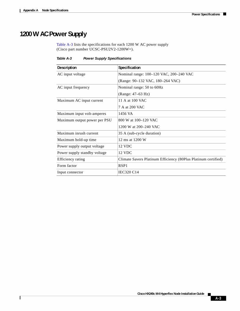
Appendix A Node SpecificationsPower Specifications
1200 W AC Power SupplyTable A-3 lists the specifications for each 1200 W AC power supply (Cisco part number UCSC-PSU2V2-1200W=).
Table A-3 Power Supply Specifications
Description Specification
AC input voltage Nominal range: 100–120 VAC, 200–240 VAC
(Range: 90–132 VAC, 180–264 VAC)
AC input frequency Nominal range: 50 to 60Hz
(Range: 47–63 Hz)
Maximum AC input current 11 A at 100 VAC
7 A at 200 VAC
Maximum input volt-amperes 1456 VA
Maximum output power per PSU 800 W at 100–120 VAC
1200 W at 200–240 VAC
Maximum inrush current 35 A (sub-cycle duration)
Maximum hold-up time 12 ms at 1200 W
Power supply output voltage 12 VDC
Power supply standby voltage 12 VDC
Efficiency rating Climate Savers Platinum Efficiency (80Plus Platinum certified)
Form factor RSP1
Input connector IEC320 C14
A-3Cisco HX240c M4 Hyperflex Node Installation Guide

Appendix A Node SpecificationsPower Specifications
1400 W AC Power SupplyTable A-4 lists the specifications for each 1400 W AC power supply (Cisco part number UCSC-PSU2-1400=).
930 W DC (Version 1) Power Supply, UCSC-PSU-930WDCTable A-5 lists the specifications for each 930 W DC power supply (Cisco part number UCSC-PSU-930WDC=).
Table A-4 1400 W Power Supply Specifications
Description Specification
AC input voltage Nominal range: 200–240 VAC
(Range: 180–264 VAC)
AC input frequency Nominal range: 50 to 60Hz
(Range: 47–63 Hz)
Maximum AC input current 8.5 A at 200 VAC
Maximum input volt-amperes 1700 VA
Maximum output power per PSU 1400 W at 200–240 VAC
Maximum inrush current 35 A (sub-cycle duration)
Maximum hold-up time 12 ms at 1200 W
Power supply output voltage 12 VDC
Power supply standby voltage 12 VDC
Efficiency rating Climate Savers Platinum Efficiency (80Plus Platinum certified)
Form factor RSP1
Input connector IEC320 C14
Table A-5 930 W DC Power Supply Specifications
Description Specification
DC input voltage range Nominal range: –48 to –60 VDC nominal
(Range: –40 to –60 VDC)
Maximum DC input current 23 A at –48 VDC
Maximum input W 1104 W
Maximum output power per PSU 930 W
Maximum inrush current 35 A (sub-cycle duration)
Maximum hold-up time 8 ms at 930 W
Power supply output voltage 12 VDC
Power supply standby voltage 12 VDC
Efficiency rating > 92% at 50% load
A-4Cisco HX240c M4 Hyperflex Node Installation Guide
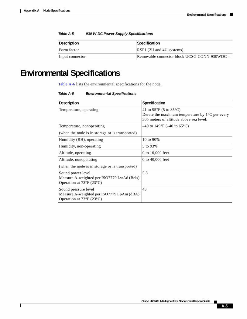
Appendix A Node SpecificationsEnvironmental Specifications
Environmental Specifications Table A-6 lists the environmental specifications for the node.
Form factor RSP1 (2U and 4U systems)
Input connector Removable connector block UCSC-CONN-930WDC=
Table A-5 930 W DC Power Supply Specifications
Description Specification
Table A-6 Environmental Specifications
Description Specification
Temperature, operating 41 to 95°F (5 to 35°C)Derate the maximum temperature by 1°C per every 305 meters of altitude above sea level.
Temperature, nonoperating
(when the node is in storage or is transported)
–40 to 149°F (–40 to 65°C)
Humidity (RH), operating 10 to 90%
Humidity, non-operating 5 to 93%
Altitude, operating 0 to 10,000 feet
Altitude, nonoperating
(when the node is in storage or is transported)
0 to 40,000 feet
Sound power levelMeasure A-weighted per ISO7779 LwAd (Bels)Operation at 73°F (23°C)
5.8
Sound pressure levelMeasure A-weighted per ISO7779 LpAm (dBA)Operation at 73°F (23°C)
43
A-5Cisco HX240c M4 Hyperflex Node Installation Guide

Appendix A Node SpecificationsEnvironmental Specifications
A-6Cisco HX240c M4 Hyperflex Node Installation Guide
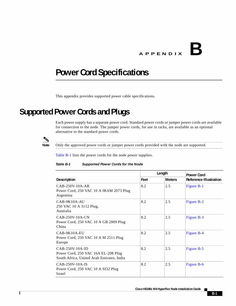
Cisco H
A
P P E N D I X B
Power Cord SpecificationsThis appendix provides supported power cable specifications.
Supported Power Cords and PlugsEach power supply has a separate power cord. Standard power cords or jumper power cords are available for connection to the node. The jumper power cords, for use in racks, are available as an optional alternative to the standard power cords.
Note Only the approved power cords or jumper power cords provided with the node are supported.
Table B-1 lists the power cords for the node power supplies.
Table B-1 Supported Power Cords for the Node
Description
Length Power Cord Reference IllustrationFeet Meters
CAB-250V-10A-ARPower Cord, 250 VAC 10 A IRAM 2073 Plug Argentina
8.2 2.5 Figure B-1
CAB-9K10A-AU250 VAC 10 A 3112 Plug, Australia
8.2 2.5 Figure B-2
CAB-250V-10A-CNPower Cord, 250 VAC 10 A GB 2009 PlugChina
8.2 2.5 Figure B-3
CAB-9K10A-EUPower Cord, 250 VAC 10 A M 2511 PlugEurope
8.2 2.5 Figure B-4
CAB-250V-10A-IDPower Cord, 250 VAC 16A EL-208 PlugSouth Africa, United Arab Emirates, India
8.2 2.5 Figure B-5
CAB-250V-10A-ISPower Cord, 250 VAC 10 A SI32 Plug Israel
8.2 2.5 Figure B-6
B-1X240c M4 Hyperflex Node Installation Guide
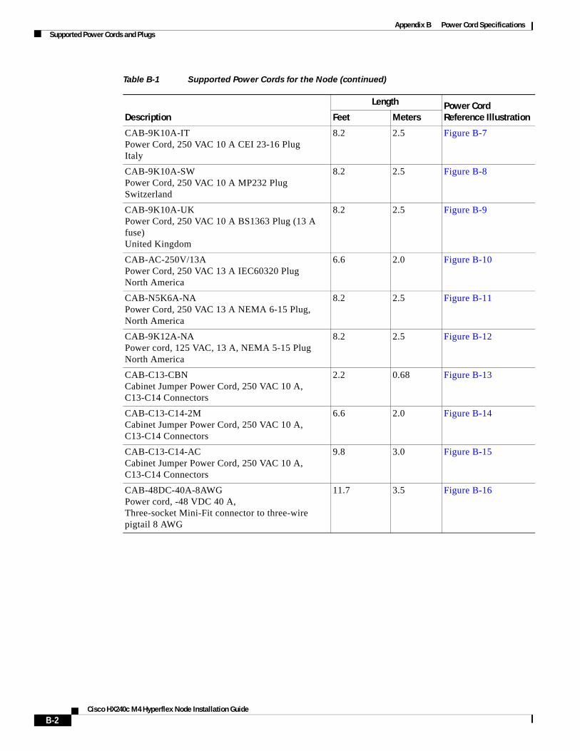
Appendix B Power Cord SpecificationsSupported Power Cords and Plugs
CAB-9K10A-ITPower Cord, 250 VAC 10 A CEI 23-16 Plug Italy
8.2 2.5 Figure B-7
CAB-9K10A-SWPower Cord, 250 VAC 10 A MP232 Plug Switzerland
8.2 2.5 Figure B-8
CAB-9K10A-UKPower Cord, 250 VAC 10 A BS1363 Plug (13 A fuse)United Kingdom
8.2 2.5 Figure B-9
CAB-AC-250V/13APower Cord, 250 VAC 13 A IEC60320 Plug North America
6.6 2.0 Figure B-10
CAB-N5K6A-NAPower Cord, 250 VAC 13 A NEMA 6-15 Plug,North America
8.2 2.5 Figure B-11
CAB-9K12A-NAPower cord, 125 VAC, 13 A, NEMA 5-15 PlugNorth America
8.2 2.5 Figure B-12
CAB-C13-CBNCabinet Jumper Power Cord, 250 VAC 10 A, C13-C14 Connectors
2.2 0.68 Figure B-13
CAB-C13-C14-2MCabinet Jumper Power Cord, 250 VAC 10 A, C13-C14 Connectors
6.6 2.0 Figure B-14
CAB-C13-C14-ACCabinet Jumper Power Cord, 250 VAC 10 A, C13-C14 Connectors
9.8 3.0 Figure B-15
CAB-48DC-40A-8AWGPower cord, -48 VDC 40 A,Three-socket Mini-Fit connector to three-wire pigtail 8 AWG
11.7 3.5 Figure B-16
Table B-1 Supported Power Cords for the Node (continued)
Description
Length Power Cord Reference IllustrationFeet Meters
B-2Cisco HX240c M4 Hyperflex Node Installation Guide
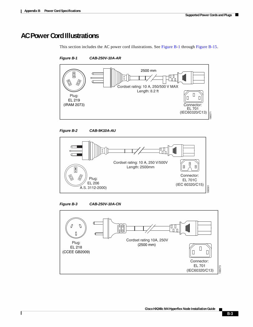
Appendix B Power Cord SpecificationsSupported Power Cords and Plugs
AC Power Cord IllustrationsThis section includes the AC power cord illustrations. See Figure B-1 through Figure B-15.
Figure B-1 CAB-250V-10A-AR
Figure B-2 CAB-9K10A-AU
Figure B-3 CAB-250V-10A-CN
1865
71
2500 mm
Cordset rating: 10 A, 250/500 V MAXLength: 8.2 ft
Plug:EL 219
(IRAM 2073) Connector:EL 701
(IEC60320/C13)
Plug:EL 206
A.S. 3112-2000)
Cordset rating: 10 A, 250 V/500VLength: 2500mm
1865
81
Connector:EL 701C
(IEC 60320/C15)
Cordset rating 10A, 250V(2500 mm)
Plug:EL 218
(CCEE GB2009)
1865
73
Connector:EL 701
(IEC60320/C13)
B-3Cisco HX240c M4 Hyperflex Node Installation Guide
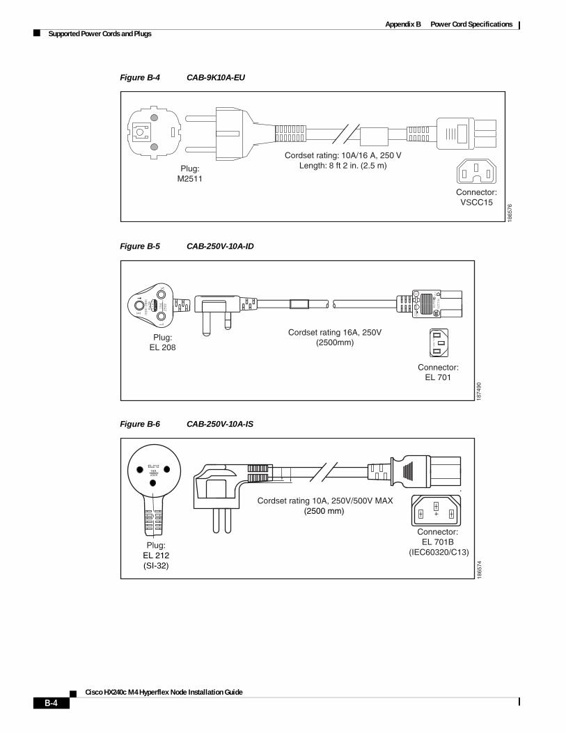
Appendix B Power Cord SpecificationsSupported Power Cords and Plugs
Figure B-4 CAB-9K10A-EU
Figure B-5 CAB-250V-10A-ID
Figure B-6 CAB-250V-10A-IS
Connector:VSCC15
Cordset rating: 10A/16 A, 250 VLength: 8 ft 2 in. (2.5 m)Plug:
M2511
1865
76
OVE
Cordset rating 16A, 250V(2500mm)
Plug:EL 208
1874
90
Connector:EL 701
Cordset rating 10A, 250V/500V MAX(2500 mm)
Plug:EL 212(SI-32)
1865
74
Connector:EL 701B
(IEC60320/C13)
EL-21216A250V
B-4Cisco HX240c M4 Hyperflex Node Installation Guide
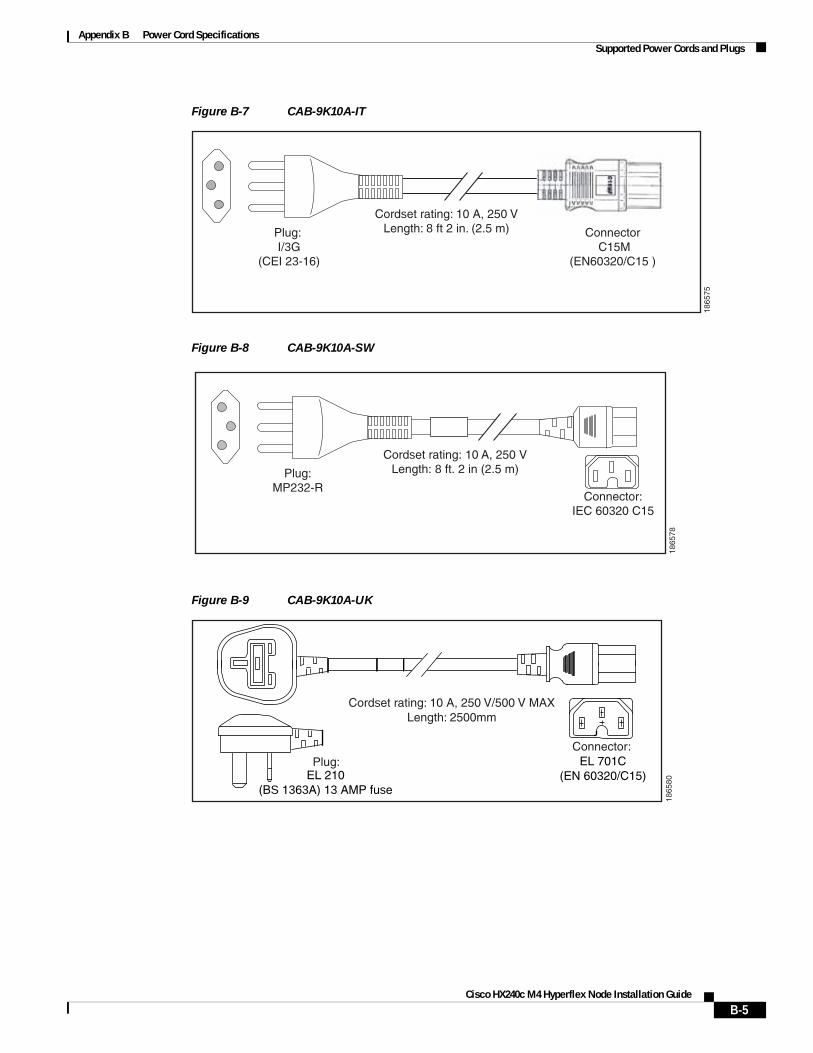
Appendix B Power Cord SpecificationsSupported Power Cords and Plugs
Figure B-7 CAB-9K10A-IT
Figure B-8 CAB-9K10A-SW
Figure B-9 CAB-9K10A-UK
Plug: I/3G
(CEI 23-16)
Connector C15M
(EN60320/C15 )
Cordset rating: 10 A, 250 VLength: 8 ft 2 in. (2.5 m)
1865
75
Plug:MP232-R
Cordset rating: 10 A, 250 VLength: 8 ft. 2 in (2.5 m)
1865
78
Connector:IEC 60320 C15
Plug:
Cordset rating: 10 A, 250 V/500 V MAXLength: 2500mm
1865
80
Connector:EL 701C
(EN 60320/C15)EL 210(BS 1363A) 13 AMP fuse
B-5Cisco HX240c M4 Hyperflex Node Installation Guide
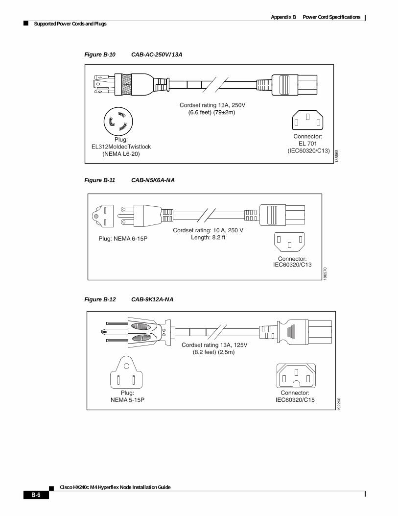
Appendix B Power Cord SpecificationsSupported Power Cords and Plugs
Figure B-10 CAB-AC-250V/13A
Figure B-11 CAB-N5K6A-NA
Figure B-12 CAB-9K12A-NA
Cordset rating 13A, 250V(6.6 feet) (79±2m)
Plug:EL312MoldedTwistlock
(NEMA L6-20)
1865
68
Connector:EL 701
(IEC60320/C13)
Cordset rating: 10 A, 250 VLength: 8.2 ft
1865
70
Plug: NEMA 6-15P
Connector:IEC60320/C13
Connector:IEC60320/C15
Cordset rating 13A, 125V(8.2 feet) (2.5m)
Plug:NEMA 5-15P
1922
60
B-6Cisco HX240c M4 Hyperflex Node Installation Guide
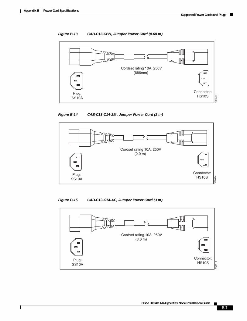
Appendix B Power Cord SpecificationsSupported Power Cords and Plugs
Figure B-13 CAB-C13-CBN, Jumper Power Cord (0.68 m)
Figure B-14 CAB-C13-C14-2M, Jumper Power Cord (2 m)
Figure B-15 CAB-C13-C14-AC, Jumper Power Cord (3 m)
Cordset rating 10A, 250V(686mm)
Plug:SS10A
1865
69
Connector:HS10S
Cordset rating 10A, 250V(2.0 m)
Plug:SS10A
3360
14
Connector:HS10S
Cordset rating 10A, 250V(3.0 m)
Plug:SS10A
3360
13
Connector:HS10S
B-7Cisco HX240c M4 Hyperflex Node Installation Guide
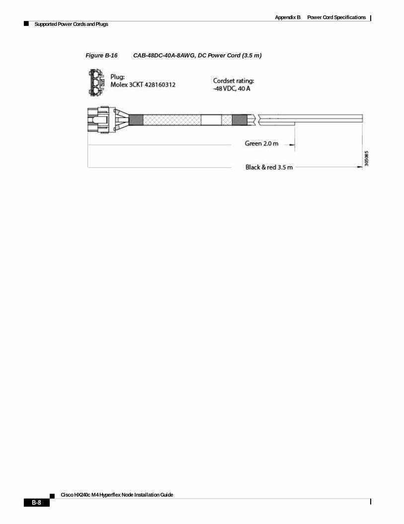
Appendix B Power Cord SpecificationsSupported Power Cords and Plugs
Figure B-16 CAB-48DC-40A-8AWG, DC Power Cord (3.5 m)
B-8Cisco HX240c M4 Hyperflex Node Installation Guide
A
P P E N D I X C
Cisco HX240c M4 Hyperflex Node Installation Guide
RAID Controller Considerations
This appendix contains the following sections:
• Supported HBA and Required Cables, page C-1
• HBA Firmware Compatibility, page C-1
• HBA Cabling, page C-2
Supported HBA and Required CablesThis node supports the HBA and cable requirements shown in Table C-1.
HBA Firmware CompatibilityFirmware on the HBA must be verified for compatibility with the current Cisco IMC and BIOS versions that are installed on the server. If not compatible, upgrade or downgrade the HBA firmware accordingly using the Host Upgrade Utility (HUU) for your firmware release to bring it to a compatible level.
See the HUU guide for your Cisco IMC release for instructions on downloading and using the utility to bring server components to compatible levels: HUU Guides
Table C-1 Cisco Hx240c RAID Options
Controller Style
Supported Server Version/Maximum Front-Facing Drives Controlled SCPM RAID Levels Required Cables
Cisco UCS 12G SAS Modular HBA
PCIe 24 internal drives No Non-RAID SFF 24 drives/expander:
(UCS-240CBLMR24=)
C-1
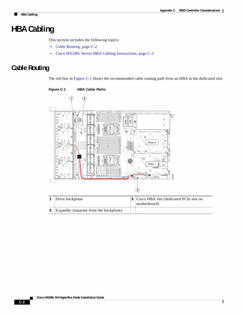
Appendix C RAID Controller ConsiderationsHBA Cabling
Cisco HX240c M4 Hyperflex Node Installation Guide
HBA CablingThis section includes the following topics:
• Cable Routing, page C-2
• Cisco HX240c Server HBA Cabling Instructions, page C-3
Cable RoutingThe red line in Figure C-1 shows the recommended cable routing path from an HBA in the dedicated slot.
Figure C-1 HBA Cable Paths
3052
46
FAN
05FA
N 06
FAN
04FA
N 03
FAN
02FA
N 01
CP
U 1
CP
U 2
SD
1
SD
2
Riser 2
Riser 1
1 2
3
1 Drive backplane 3 Cisco HBA slot (dedicated PCIe slot on motherboard)
2 Expander (separate from the backplane)
C-2
Appendix C RAID Controller ConsiderationsHBA Cabling
Cisco HX240c M4 Hyperflex Node Installation Guide
Cisco HX240c Server HBA Cabling InstructionsThis section contains cabling instructions for controlling front-facing drives using the supported cables:
The node has a backplane and a separate SAS expander.
Cisco UCS 12G Modular HBA
This option can control up to 24 drives.
The required UCS-240CBLMR24= cable kit has one cable with a mini-SAS HD connector on each end.
Make the following connections:
1. Connect one end of the cable to the HBA.
2. Connect the other end of the cable to the single mini-SAS HD connector on the expander.
C-3

Appendix C RAID Controller ConsiderationsHBA Cabling
C-4Cisco HX240c M4 Hyperflex Node Installation Guide

Appendix C RAID Controller ConsiderationsHBA Cabling
C-5Cisco HX240c M4 Hyperflex Node Installation Guide

Appendix C RAID Controller ConsiderationsHBA Cabling
C-6Cisco HX240c M4 Hyperflex Node Installation Guide

Appendix C RAID Controller ConsiderationsHBA Cabling
C-7Cisco HX240c M4 Hyperflex Node Installation Guide

Appendix C RAID Controller ConsiderationsHBA Cabling
C-8Cisco HX240c M4 Hyperflex Node Installation Guide

Appendix C RAID Controller ConsiderationsHBA Cabling
Cisco HX240c M4 Hyperflex Node Installation Guide
C-9

Appendix C RAID Controller ConsiderationsHBA Cabling
C-10Cisco HX240c M4 Hyperflex Node Installation Guide

Appendix C RAID Controller ConsiderationsHBA Cabling
C-11Cisco HX240c M4 Hyperflex Node Installation Guide

Appendix C RAID Controller ConsiderationsHBA Cabling
C-12Cisco HX240c M4 Hyperflex Node Installation Guide

Appendix C RAID Controller Considerations
HBA Cabling
C-13Cisco HX240c M4 Hyperflex Node Installation Guide

Appendix C RAID Controller ConsiderationsHBA Cabling
C-14Cisco HX240c M4 Hyperflex Node Installation Guide
A
P P E N D I X D
Cisco HX240c M4 Hyperflex Node Installation Guide
GPU Card Installation
This appendix contains the following topics:
• GPU Card Configuration Rules, page D-1
• Requirement For All Supported GPUs: Memory-Mapped I/O Greater than 4 GB, page D-2
• Replacing a GPU Card, page D-3
GPU Card Configuration RulesObserve the following rules when installing a GPU in the node:
• Only one GPU card per node is supported. The GPU card must be installed in PCIe riser 2, slot 5.
• All GPU cards require two CPUs and two power supplies in the node (minimum 1200 W, recommended 1400 W).
Caution When using NVIDIA GPU cards, you must preserve at least 10 mm of space between nodes to ensure adequate air flow. When using GPU cards, the operating temperature range is 32° to 95° F (0° to 35° C).
• NVIDIA GPUs can support only less-than 1 TB of memory in the node. Therefore, do not install more than fourteen 64-GB DIMMs when using an NVIDIA GPU card in this node.
D-1

Appendix D GPU Card Installation
Cisco HX240c M4 Hyperflex Node Installation Guide
Requirement For All Supported GPUs: Memory-Mapped I/O Greater than 4 GBAll supported GPU cards require enablement of the BIOS setting that allows greater than 4 GB of memory-mapped I/O (MMIO).
Standalone Node
If the node is used in standalone mode, this BIOS setting is enabled by default:
Advanced > PCI Configuration > Memory Mapped I/O Above 4 GB [Enabled]
If you need to change this from a different setting, enter the BIOS Setup Utility by pressing F2 when prompted during bootup.
Cisco UCS Manager Controlled Node
If the node is integrated with Cisco UCS Manager and controlled by a service profile, this setting is not enabled by default in the service profile. You must enable it with a BIOS policy in your service profile.
Step 1 Refer to the Cisco UCS Manager configuration guide (GUI or CLI) for your release for instructions on configuring service profiles:
Cisco UCS Manager Configuration Guides
Step 2 Refer to the chapter on Configuring Server-Related Policies > Configuring BIOS Settings.
Step 3 In the section of your profile for PCI Configuration BIOS Settings, set Memory Mapped IO Above 4GB Config to one of the following:
• Enabled—Maps I/O of 64-bit PCI devices to 64 GB or greater address space.
• Platform Default—The policy uses the value for this attribute contained in the BIOS defaults for the node. Use this only if you know that the node BIOS is set to use the default enabled setting for this item.
Step 4 Reboot the node.
Note Cisco UCS Manager pushes BIOS configuration changes through a BIOS policy or default BIOS settings to the Cisco Integrated Management Controller (CIMC) buffer. These changes remain in the buffer and do not take effect until the node is rebooted.
D-2
Appendix D GPU Card Installation
Cisco HX240c M4 Hyperflex Node Installation Guide
Replacing a GPU Card Use this section to install or replace a GPU card that draws less than 300 W power. Use this section to install the following GPUs:
– GRID K1
– GRID K2
Step 1 Shut down and power off the node as described in Shutting Down and Powering Off the Node, page 3-8.
Step 2 Slide the node out the front of the rack far enough so that you can remove the top cover. You might have to detach cables from the rear panel to provide clearance.
Caution If you cannot safely view and access the component, remove the node from the rack.
Step 3 Remove the top cover as described in Removing and Replacing the Node Top Cover, page 3-9.
Step 4 Remove PCIe riser 2 and any existing GPU card in slot 5:
a. Lift straight up on both ends of the riser to disengage its circuit board from the socket on the motherboard. Set the riser on an antistatic mat.
b. On the bottom of the riser, loosen the single thumbscrew that holds the securing plate. See Figure D-1.
c. Swing open the securing plate and remove it from the riser to provide access.
d. Swing open the card-tab retainer that secures the back-panel tab of the card (see Figure D-1).
e. Pull evenly on both ends of the GPU card to disengage it from the socket on the PCIe riser (or remove a blanking panel) and then set the card aside.
Step 5 Install your GPU card into riser 2, PCIe slot 5. See Figure 3-17 for the riser and slot locations.
a. Align the GPU card with the socket on the riser, and then gently push the card’s edge connector into the socket. Press evenly on both corners of the card to avoid damaging the connector.
b. Connect the GPU card power cable into the GPU card and into the GPU POWER connector on the PCIe riser (see Figure D-1).
c. Return the securing plate to the riser. Insert the two hinge-tabs into the two slots on the riser, and then swing the securing plate closed.
d. Tighten the single thumbscrew that holds the securing plate.
e. Close the card-tab retainer (see Figure D-1).
f. Position the PCIe riser over its socket on the motherboard and over its alignment features in the chassis (see Figure 3-16).
g. Carefully push down on both ends of the PCIe riser to fully engage its circuit board connector with the socket on the motherboard.
Step 6 Replace the top cover.
Step 7 Replace the node in the rack, replace cables, and then power on the node by pressing the Power button.
D-3
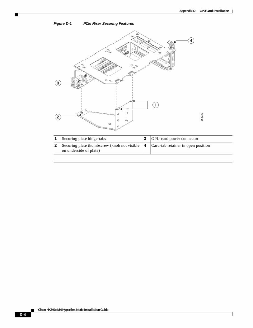
Appendix D GPU Card Installation
Figure D-1 PCIe Riser Securing Features
1 Securing plate hinge-tabs 3 GPU card power connector
2 Securing plate thumbscrew (knob not visible on underside of plate)
4 Card-tab retainer in open position
3532
39
4
3
2
1
D-4Cisco HX240c M4 Hyperflex Node Installation Guide

Appendix D GPU Card Installation
D-5Cisco HX240c M4 Hyperflex Node Installation Guide

Appendix D GPU Card Installation
D-6Cisco HX240c M4 Hyperflex Node Installation Guide

Appendix D GPU Card Installation
D-7Cisco HX240c M4 Hyperflex Node Installation Guide

Appendix D GPU Card Installation
D-8Cisco HX240c M4 Hyperflex Node Installation Guide

Appendix D GPU Card Installation
D-9Cisco HX240c M4 Hyperflex Node Installation Guide

Appendix D GPU Card Installation
D-10Cisco HX240c M4 Hyperflex Node Installation Guide

Appendix D GPU Card Installation
D-11Cisco HX240c M4 Hyperflex Node Installation Guide

Appendix D GPU Card Installation
D-12Cisco HX240c M4 Hyperflex Node Installation Guide

Appendix D GPU Card Installation
D-13Cisco HX240c M4 Hyperflex Node Installation Guide

Appendix D GPU Card Installation
D-14Cisco HX240c M4 Hyperflex Node Installation Guide

Appendix D GPU Card Installation
D-15Cisco HX240c M4 Hyperflex Node Installation Guide

Appendix D GPU Card Installation
D-16Cisco HX240c M4 Hyperflex Node Installation Guide

Appendix D GPU Card Installation
D-17Cisco HX240c M4 Hyperflex Node Installation Guide

Appendix D GPU Card Installation
D-18Cisco HX240c M4 Hyperflex Node Installation Guide

Appendix D GPU Card Installation
D-19Cisco HX240c M4 Hyperflex Node Installation Guide

Appendix D GPU Card Installation
D-20Cisco HX240c M4 Hyperflex Node Installation Guide

Appendix D GPU Card Installation
D-21Cisco HX240c M4 Hyperflex Node Installation Guide

Appendix D GPU Card Installation
D-22Cisco HX240c M4 Hyperflex Node Installation Guide