Cisco Connected Grid Ethernet Switch Module … fileMeetingPlace, MeetingPlace Chime So und, MGX,...
46
Cisco Systems, Inc. www.cisco.com Cisco has more than 200 offices worldwide. Addresses, phone numbers, and fax numbers are listed on the Cisco website at www.cisco.com/go/offices. Cisco Connected Grid Ethernet Switch Module Interface Card Getting Started Guide First Published: May 2012 Last Updated: January 2014 Part Number: OL-23421-02 Text Part Number: OL-23421-02
Transcript of Cisco Connected Grid Ethernet Switch Module … fileMeetingPlace, MeetingPlace Chime So und, MGX,...
Cisco Connected Grid Ethernet Switch Module Interface Card Getting Started GuideFirst Published: May 2012Last Updated: January 2014Part Number: OL-23421-02
Cisco Systems, Inc. www.cisco.com
Cisco has more than 200 offices worldwide. Addresses, phone numbers, and fax numbers are listed on the Cisco website at www.cisco.com/go/offices.
Text Part Number: OL-23421-02

THE SPECIFICATIONS AND INFORMATION REGARDING THE PRODUCTS IN THIS MANUAL ARE SUBJECT TO CHANGE WITHOUT NOTICE. ALL STATEMENTS, INFORMATION, AND RECOMMENDATIONS IN THIS MANUAL ARE BELIEVED TO BE ACCURATE BUT ARE PRESENTED WITHOUT WARRANTY OF ANY KIND, EXPRESS OR IMPLIED. USERS MUST TAKE FULL RESPONSIBILITY FOR THEIR APPLICATION OF ANY PRODUCTS.
THE SOFTWARE LICENSE AND LIMITED WARRANTY FOR THE ACCOMPANYING PRODUCT ARE SET FORTH IN THE INFORMATION PACKET THAT SHIPPED WITH THE PRODUCT AND ARE INCORPORATED HEREIN BY THIS REFERENCE. IF YOU ARE UNABLE TO LOCATE THE SOFTWARE LICENSE OR LIMITED WARRANTY, CONTACT YOUR CISCO REPRESENTATIVE FOR A COPY.
The Cisco implementation of TCP header compression is an adaptation of a program developed by the University of California, Berkeley (UCB) as part of UCB’s public domain version of the UNIX operating system. All rights reserved. Copyright © 1981, Regents of the University of California.
NOTWITHSTANDING ANY OTHER WARRANTY HEREIN, ALL DOCUMENT FILES AND SOFTWARE OF THESE SUPPLIERS ARE PROVIDED “AS IS” WITH ALL FAULTS. CISCO AND THE ABOVE-NAMED SUPPLIERS DISCLAIM ALL WARRANTIES, EXPRESSED OR IMPLIED, INCLUDING, WITHOUT LIMITATION, THOSE OF MERCHANTABILITY, FITNESS FOR A PARTICULAR PURPOSE AND NONINFRINGEMENT OR ARISING FROM A COURSE OF DEALING, USAGE, OR TRADE PRACTICE.
IN NO EVENT SHALL CISCO OR ITS SUPPLIERS BE LIABLE FOR ANY INDIRECT, SPECIAL, CONSEQUENTIAL, OR INCIDENTAL DAMAGES, INCLUDING, WITHOUT LIMITATION, LOST PROFITS OR LOSS OR DAMAGE TO DATA ARISING OUT OF THE USE OR INABILITY TO USE THIS MANUAL, EVEN IF CISCO OR ITS SUPPLIERS HAVE BEEN ADVISED OF THE POSSIBILITY OF SUCH DAMAGES.
CCDE, CCENT, Cisco Eos, Cisco HealthPresence, the Cisco logo, Cisco Lumin, Cisco Nexus, Cisco StadiumVision, Cisco TelePresence, Cisco WebEx, DCE, and Welcome to the Human Network are trademarks; Changing the Way We Work, Live, Play, and Learn and Cisco Store are service marks; and Access Registrar, Aironet, AsyncOS, Bringing the Meeting To You, Catalyst, CCDA, CCDP, CCIE, CCIP, CCNA, CCNP, CCSP, CCVP, Cisco, the Cisco Certified Internetwork Expert logo, Cisco IOS, Cisco Press, Cisco Systems, Cisco Systems Capital, the Cisco Systems logo, Cisco Unity, Collaboration Without Limitation, EtherFast, EtherSwitch, Event Center, Fast Step, Follow Me Browsing, FormShare, GigaDrive, HomeLink, Internet Quotient, IOS, iPhone, iQuick Study, IronPort, the IronPort logo, LightStream, Linksys, MediaTone, MeetingPlace, MeetingPlace Chime Sound, MGX, Networkers, Networking Academy, Network Registrar, PCNow, PIX, PowerPanels, ProConnect, ScriptShare, SenderBase, SMARTnet, Spectrum Expert, StackWise, The Fastest Way to Increase Your Internet Quotient, TransPath, WebEx, and the WebEx logo are registered trademarks of Cisco Systems, Inc. and/or its affiliates in the United States and certain other countries.
Cisco and the Cisco logo are trademarks or registered trademarks of Cisco and/or its affiliates in the U.S. and other countries. To view a list of Cisco trademarks, go to this URL: www.cisco.com/go/trademarks. Third-party trademarks mentioned are the property of their respective owners. The use of the word partner does not imply a partnership relationship between Cisco and any other company. (1110R)
No combinations are authorized or intended under this document.
Any Internet Protocol (IP) addresses used in this document are not intended to be actual addresses. Any examples, command display output, and figures included in the document are shown for illustrative purposes only. Any use of actual IP addresses in illustrative content is unintentional and coincidental.
© 2012–2014 Cisco Systems, Inc. All rights reserved.
CiscOL-23421-02
C O N T E N T S
Preface iii
Purpose iii
Document Conventions iii
Related Publications iv
Obtaining Documentation and Submitting a Service Request iv
C H A P T E R 1 Product Overview 1-1
Switch Models 1-1
Ports 1-2
Port Locations 1-2
Port Labeling 1-3
10/100BASE-T Ports 1-4
PoE and PoE+ Ports 1-4
10/100 Mb/s SFP Module Slots 1-5
100/1000 Mb/s SFP Module Slots 1-5
Dual-Purpose Gigabit Ethernet Ports 1-5
Supported SFPs 1-6
LEDs 1-7
Router Compact Flash Memory Cards 1-9
C H A P T E R 2 Installation 2-1
Pre-Installation 2-1
Installation Warning Statements 2-1
Installation 2-2
Connecting to the Network 2-5
Connecting the Copper Switch Module 2-5
Connecting the Fiber Switch Module 2-6
Removing the Switch Module 2-7
C H A P T E R 3 Express Setup 3-1
System Requirements 3-1
Express Setup 3-1
1o Connected Grid Ethernet Switch Module Interface Card Getting Started Guide
Contents
Troubleshooting Express Setup 3-5
Resetting the Switch Module 3-5
C H A P T E R 4 Managing the Switch Module 4-1
Using the Device Manager 4-1
Cisco Configuration Professional 4-1
Other Management Options 4-2
Accessing the Switch Module 4-2
Disconnecting from the Switch Module 4-3
Connecting Devices to the Switch Module 4-4
10/100BASE-T Ports 4-4
SFP Module Slots 4-5
Dual-Purpose Port with RJ-45 and SFP Connectors 4-7
Verifying Port Connectivity 4-9
A P P E N D I X A Cable and Connectors A-1
Connector Specifications A-1
10/100BASE-T Ports A-1
SFP Module Connectors A-1
Dual-Purpose Ports A-2
Cables and Adapters A-2
SFP Module Cables A-2
Cable Pinouts A-4
2Cisco Connected Grid Ethernet Switch Module Interface Card Getting Started Guide
OL-23421-02
Preface
PurposeThis guide describes the hardware features of the Cisco Connected Grid Ethernet Switch Module Interface Card (switch module). It describes how to install the switch module in the Cisco 2010 Connected Grid Router, and how to configure it.
This guide also describes how to:
• Access the switch module from the host router
• Connect devices to the switch module ports
• Manage the switch module
• Perform Express Setup troubleshooting
Document Conventions
Note Means reader take note. Notes contain helpful suggestions or references to materials not contained in this manual.
Caution Means reader be careful. In this situation, you might do something that could result in equipment damage or loss of data.
iiiCisco Connected Grid Ethernet Switch Module Interface Card Getting Started Guide
OL-23421-02
Related Publications
Note Before installing, configuring, or upgrading the switch, see the release notes on Cisco.com for the latest information.
• Release Notes for Cisco 2520 Connected Grid Switch and Ethernet Switch Module
• Cisco Connected Grid Ethernet Switch Module Interface Card Software Configuration Guide
• Regulatory Compliance and Safety Information for Cisco Connected Grid Router 2000 Series Routers
• Cisco Connected Grid Modules documentation: http://www.cisco.com/en/US/products/ps10984/tsd_products_support_series_home.html
• Cisco 2000 Series Connected Grid Routers documentation: http://www.cisco.com/en/US/products/ps10977/tsd_products_support_series_home.html
• Cisco SFP documents: http://www.cisco.com/en/US/products/hw/modules/ps5455/prod_installation_guides_list.html
Obtaining Documentation and Submitting a Service RequestFor information on obtaining documentation, submitting a service request, and gathering additional information, see the monthly What’s New in Cisco Product Documentation, which also lists all new and revised Cisco technical documentation, at:
http://www.cisco.com/en/US/docs/general/whatsnew/whatsnew.html
Subscribe to the What’s New in Cisco Product Documentation as a Really Simple Syndication (RSS) feed and set content to be delivered directly to your desktop using a reader application. The RSS feeds are a free service and Cisco currently supports RSS version 2.0.
Warning IMPORTANT SAFETY INSTRUCTIONS
This warning symbol means danger. You are in a situation that could cause bodily injury. Before you work on any equipment, be aware of the hazards involved with electrical circuitry and be familiar with standard practices for preventing accidents. Use the statement number provided at the end of each warning to locate its translation in the translated safety warnings that accompanied this device. Statement 1071
SAVE THESE INSTRUCTIONS
ivCisco Connected Grid Ethernet Switch Module Interface Card Getting Started Guide
OL-23421-02
Cisco Connected Grid Ethernet SOL-23421-02
C H A P T E R 1
Product OverviewThis chapter describes the Cisco Connected Grid Ethernet Switch Module Interface Card, hereafter referred to as the switch module. The switch deployed together with the Cisco 2010 Connected Grid Router (CGR 2010) offers utilities a rugged networking solution to enable reliable and secure two-way communication for substation automation.
Note The Cisco CGR 2010 router must be running Cisco IOS Release 15.1(4)M or higher to run the switch module.
• Switch Models, page 1-1
• Ports, page 1-2
• LEDs, page 1-7
• Router Compact Flash Memory Cards, page 1-9
Switch ModelsTable 1-1 Connected Grid Ethernet Switch Module Interface Card Models
Mode Description
GRWIC-D-ES-6S (SFP fiber model)
4 100 Mb/s SFP (small form-factor pluggable) module slots, 1 Gigabit Ethernet (GE) dual-purpose port (1 10/100/1000BASE-T port and 1 100/1000 Mb/s SFP module slot), 1 100/1000 M/bs SFP module slot.
GRWIC-D-ES-2S-8PC (Copper model)
8 10/100BASE-T ports, 1 GE dual-purpose port (1 10/100/1000BASE-T port and 1 100/1000 Mb/s SFP module slot), 1 100/1000 Mb/s SFP module slot.
Note The first four 10/100BASE-T ports (FE0/1, FE0/2, FE0/3, FE0/4) are PoE+1 ports.
1. PoE+ = Power over Ethernet plus (provides up to 30 W per port).
1-1witch Module Interface Card Getting Started Guide
Chapter 1 Product OverviewPorts
Ports • Port Locations, page 1-2
• Port Labeling, page 1-3
• 10/100BASE-T Ports, page 1-4
• PoE and PoE+ Ports, page 1-4
• 10/100 Mb/s SFP Module Slots, page 1-5
• 100/1000 Mb/s SFP Module Slots, page 1-5
• Dual-Purpose Gigabit Ethernet Ports, page 1-5
• Supported SFPs, page 1-6
Port Locations
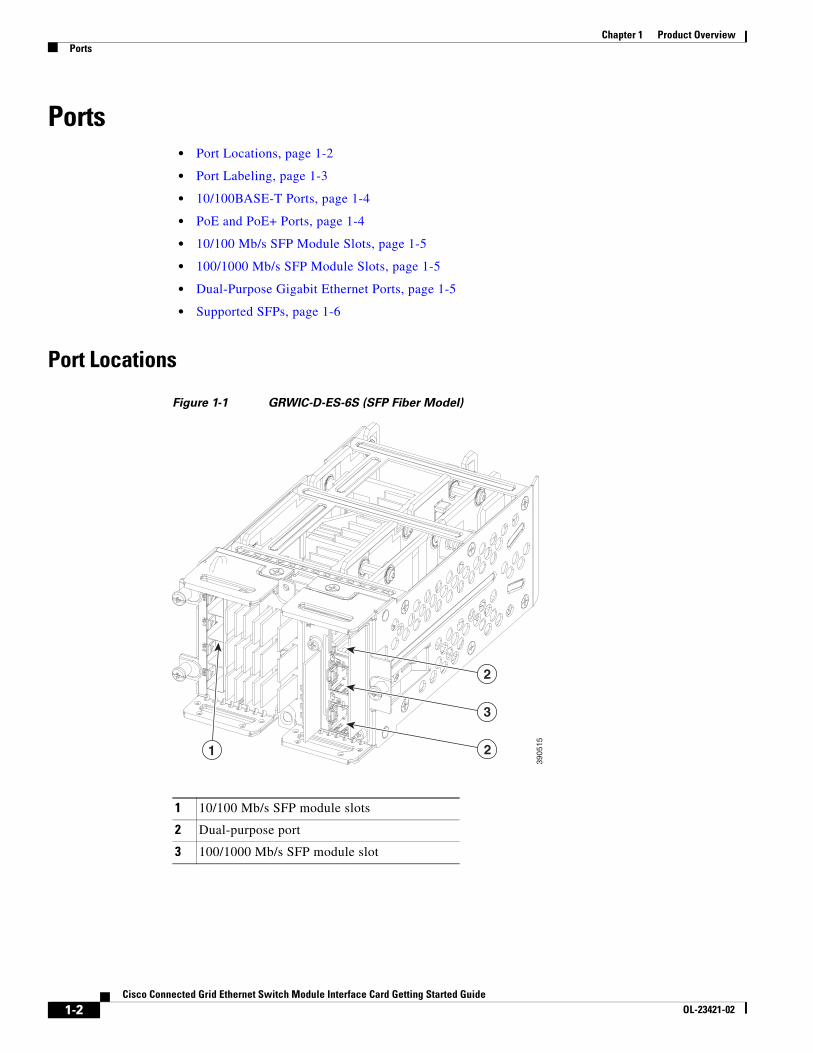
Figure 1-1 GRWIC-D-ES-6S (SFP Fiber Model)
1 10/100 Mb/s SFP module slots
2 Dual-purpose port
3 100/1000 Mb/s SFP module slot
3905
15
1
3
2
2
1-2Cisco Connected Grid Ethernet Switch Module Interface Card Getting Started Guide
OL-23421-02
Chapter 1 Product OverviewPorts
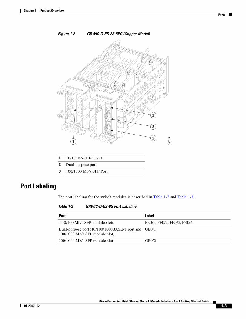
Figure 1-2 GRWIC-D-ES-2S-8PC (Copper Model)
Port LabelingThe port labeling for the switch modules is described in Table 1-2 and Table 1-3.
1 10/100BASET-T ports
2 Dual-purpose port
3 100/1000 Mb/s SFP Port39
0514
1
3
2
2
Table 1-2 GRWIC-D-ES-6S Port Labeling
Port Label
4 10/100 Mb/s SFP module slots FE0/1, FE0/2, FE0/3, FE0/4
Dual-purpose port (10/100/1000BASE-T port and 100/1000 Mb/s SFP module slot)
GE0/1
100/1000 Mb/s SFP module slot GE0/2
1-3Cisco Connected Grid Ethernet Switch Module Interface Card Getting Started Guide
OL-23421-02
Chapter 1 Product OverviewPorts
10/100BASE-T PortsYou can set the 10/100BASE-T ports on the switch to operate in any combination of half duplex, full duplex, or 10 or 100 Mb/s. You can set the ports for speed and duplex auto-negotiation. The default setting is auto-negotiate.
When set for auto-negotiation, the switch determines the speed and duplex settings of the attached device, and advertises its own capabilities. If the connected device also supports auto-negotiation, the switch negotiates the best connection (the fastest line speed that both devices support and full-duplex transmission if the attached device supports it), and configures itself accordingly. In all cases, the attached device must be within 328 feet (100 meters).
The 10/100BASE-T ports use RJ-45 connectors with Ethernet pinouts. The maximum cable length is 328 feet (100 meters). The 100BASE-TX traffic requires Category 5, Category 5e, or Category 6 unshielded twisted pair (UTP) cable. The 10BASE-T traffic can use Category 3 or Category 4 UTP cable.
Note On the GRWIC-D-ES-2S-8PC switch module, the first four 10/100 Fast Ethernet ports (FE0/1, FE0/2, FE0/3, FE0/4) are PoE+ ports.
PoE and PoE+ PortsThe first four 10/100 Fast Ethernet ports (FE0/1, FE0/2, FE0/3, FE0/4) on the GRWIC-D-ES-2S-8PC switch module are PoE+ ports.
Warning Voltages that present a shock hazard may exist on Power over Ethernet (PoE) circuits if interconnections are made using uninsulated exposed metal contacts, conductors, or terminals. Avoid using such interconnection methods, unless the exposed metal parts are located within a restricted access location and users and service people who are authorized within the restricted access location are made aware of the hazard. A restricted access area can be accessed only through the use of a special tool, lock and key or other means of security. Statement 1072
These PoE+ ports provide:
• Support for IEEE 802.3af-compliant powered devices (up to 15.4 W PoE per port) and support for IEEE 802.3at-compliant powered devices (up to 30 W PoE+ per port).
• Support for prestandard Cisco powered devices.
• Configurable support for Cisco intelligent power management, including:
– enhanced power negotiation
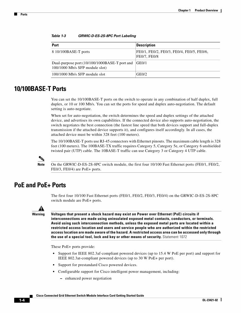
Table 1-3 GRWIC-D-ES-2S-8PC Port Labeling
Port Description
8 10/100BASE-T ports FE0/1, FE0/2, FE0/3, FE0/4, FE0/5, FE0/6, FE0/7, FE0/8
Dual-purpose port (10/100/1000BASE-T port and 100/1000 Mb/s SFP module slot)
GE0/1
100/1000 Mb/s SFP module slot GE0/2
1-4Cisco Connected Grid Ethernet Switch Module Interface Card Getting Started Guide
OL-23421-02
Chapter 1 Product OverviewPorts
– power reservation
– per-port power policing
On the GRWIC-D-ES-2S-8PC model (Copper model), the first four 10/100BASE-T ports (FE0/1, FE0/2, FE0/3, FE0/4) are PoE+ ports. A maximum of two PoE+ ports or four PoE ports can be supported at one time.
For information about configuring and monitoring PoE/PoE+ ports, see the “Interface Configuration” chapter of the Cisco Connected Grid Ethernet Switch Module Interface Card Software Configuration Guide on Cisco.com.
For information about port connections and port specifications, see the “Connecting Devices to the Switch Module” section on page 4-4 and the “Cable and Connectors” appendix.
Note The output of the PoE+ circuit has been evaluated as a Limited Power Source (LPS) per IEC 60950-1.
10/100 Mb/s SFP Module SlotsThe IEEE 802.3u 100 Mb/s SFP module slots provide full-duplex 100 Mb/s connectivity over multi-mode (MM) fiber cables or single-mode (SM) fiber cables. These ports use a SFP fiber-optic transceiver module that accepts a dual LC connector. Check the SFP specifications for the cable type and length.
100/1000 Mb/s SFP Module SlotsThe IEEE 802.3u 1000 Mb/s SFP module slots provide full-duplex 100 or 1000 Mb/s connectivity over multi-mode (MM) fiber cables or single-mode (SM) fiber cables. These ports use a SFP fiber-optic transceiver module that accepts a dual LC connector. Check the SFP specifications for the cable type and length.
Dual-Purpose Gigabit Ethernet PortsYou can configure the dual-purpose ports on the switch as either 10/100/1000 Ethernet ports or as SFP module ports. You can set the 10/100/1000 Ethernet ports to autonegotiate, or you can configure them as fixed 10, 100, or 1000 Mb/s Ethernet ports.
By default, the switch selects the medium for each dual-purpose port (10/100/1000BASE-T or SFP). When a link is achieved on one media type, the switch disables the other media type until the active link goes down. If links are active on both media, the SFP module port has priority, but you can use the media-type interface configuration command to manually designate the port as an RJ-45 port or an SFP port.
You can configure the speed and duplex settings consistent with the selected media type. For information on configuring interfaces, see the “Interface Configuration” chapter of the Cisco Connected Grid Ethernet Switch Module Interface Card Software Configuration Guide on Cisco.com.
For more information on the SFP module ports see the “Supported SFPs” section on page 1-6 and the information on the SFP modules connectors and cables in the “Cable and Connectors” appendix.
1-5Cisco Connected Grid Ethernet Switch Module Interface Card Getting Started Guide
OL-23421-02
Chapter 1 Product OverviewPorts
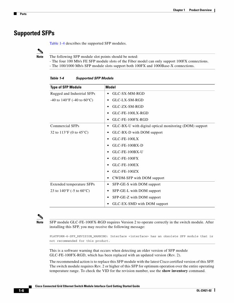
Supported SFPsTable 1-4 describes the supported SFP modules.
Note The following SFP module slot points should be noted: - The four 100 Mb/s FE SFP module slots of the Fiber model can only support 100FX connections. - The 100/1000 Mb/s SFP module slots support both 100FX and 1000Base-X connections.
Note SFP module GLC-FE-100FX-RGD requires Version 2 to operate correctly in the switch module. After installing this SFP, you may receive the following message: PLATFORM-4-SFP_REVISION_WARNING: Interface <interface> has an obsolete SFP module that is
not recommended for this product.
This is a software warning that occurs when detecting an older version of SFP module GLC-FE-100FX-RGD, which has been replaced with an updated version (Rev. 2).
The recommended action is to replace this SFP module with the latest Cisco certified version of this SFP. The switch module requires Rev. 2 or higher of this SFP for optimum operation over the entire operating temperature range. To check the VID for the revision number, use the show inventory command.
Table 1-4 Supported SFP Models
Type of SFP Module Model
Rugged and Industrial SFPs
-40 to 140°F (-40 to 60°C)
• GLC-SX-MM-RGD
• GLC-LX-SM-RGD
• GLC-ZX-SM-RGD
• GLC-FE-100LX-RGD
• GLC-FE-100FX-RGD
Commercial SFPs
32 to 113°F (0 to 45°C)
• GLC-BX-U with digital optical monitoring (DOM) support
• GLC-BX-D with DOM support
• GLC-FE-100LX
• GLC-FE-100BX-D
• GLC-FE-100BX-U
• GLC-FE-100FX
• GLC-FE-100EX
• GLC-FE-100ZX
• CWDM-SFP with DOM support
Extended temperature SFPs
23 to 140°F (-5 to 60°C)
• SFP-GE-S with DOM support
• SFP-GE-L with DOM support
• SFP-GE-Z with DOM support
• GLC-EX-SMD with DOM support
1-6Cisco Connected Grid Ethernet Switch Module Interface Card Getting Started Guide
OL-23421-02
Chapter 1 Product OverviewLEDs
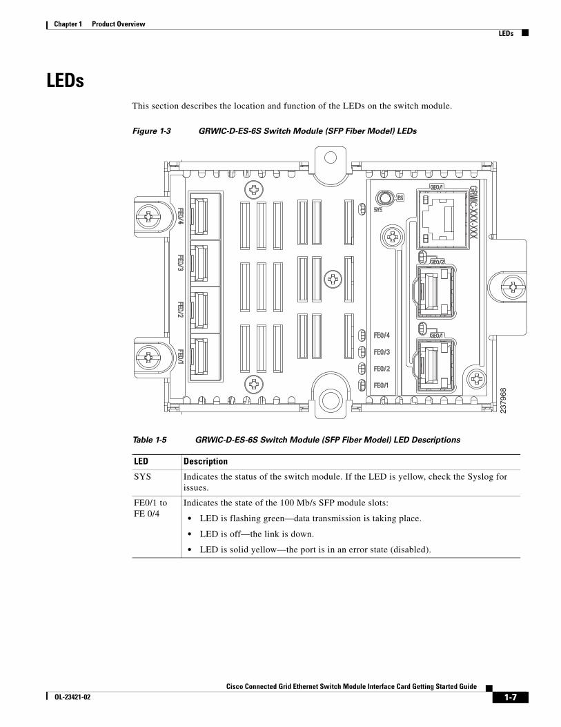
LEDsThis section describes the location and function of the LEDs on the switch module.
Figure 1-3 GRWIC-D-ES-6S Switch Module (SFP Fiber Model) LEDs
Table 1-5 GRWIC-D-ES-6S Switch Module (SFP Fiber Model) LED Descriptions
LED Description
SYS Indicates the status of the switch module. If the LED is yellow, check the Syslog for issues.
FE0/1 to FE 0/4
Indicates the state of the 100 Mb/s SFP module slots:
• LED is flashing green—data transmission is taking place.
• LED is off—the link is down.
• LED is solid yellow—the port is in an error state (disabled).
2379
68
1-7Cisco Connected Grid Ethernet Switch Module Interface Card Getting Started Guide
OL-23421-02
Chapter 1 Product OverviewLEDs
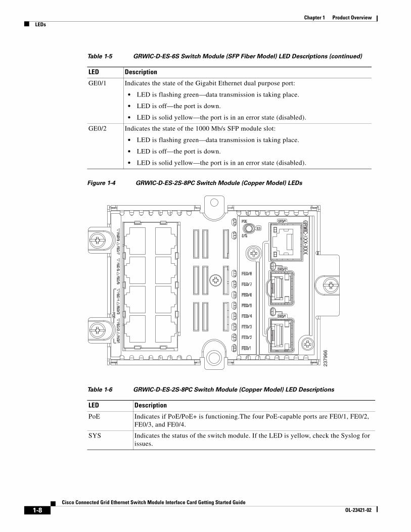
Figure 1-4 GRWIC-D-ES-2S-8PC Switch Module (Copper Model) LEDs
GE0/1 Indicates the state of the Gigabit Ethernet dual purpose port:
• LED is flashing green—data transmission is taking place.
• LED is off—the port is down.
• LED is solid yellow—the port is in an error state (disabled).
GE0/2 Indicates the state of the 1000 Mb/s SFP module slot:
• LED is flashing green—data transmission is taking place.
• LED is off—the port is down.
• LED is solid yellow—the port is in an error state (disabled).
Table 1-5 GRWIC-D-ES-6S Switch Module (SFP Fiber Model) LED Descriptions (continued)
LED Description
2379
66
Table 1-6 GRWIC-D-ES-2S-8PC Switch Module (Copper Model) LED Descriptions
LED Description
PoE Indicates if PoE/PoE+ is functioning.The four PoE-capable ports are FE0/1, FE0/2, FE0/3, and FE0/4.
SYS Indicates the status of the switch module. If the LED is yellow, check the Syslog for issues.
1-8Cisco Connected Grid Ethernet Switch Module Interface Card Getting Started Guide
OL-23421-02
Chapter 1 Product OverviewRouter Compact Flash Memory Cards
Router Compact Flash Memory CardsCompact flash cards can help you configure new or replacement routers, and to recover the configuration of a failed router. For example, if the Connected Grid Swap Drive feature is enabled, you can transfer the same system configuration information from one router to another by using a compact flash memory card (or compact flash card) while the routers are operating. This is done by inserting an optional compact flash card in slot CF1 and copying all contents of CF0. After the copy operation is completed, you can remove and insert this compact flash card unit in slot CF0 of either a new router or a replacement router for a failed unit. When the new or replacement router is rebooted, it uses the configuration from the compact flash card as the running and startup configuration. This functionality enables you to quickly configure new or replacement routers with a standard configuration with little or no manual configuration required.
FE0/1 to FE 0/8
Indicates state of the Fast Ethernet ports:
• LED is flashing green—data transmission is taking place.
• LED is off—the link is down.
• LED is solid yellow—the port is in an error state (disabled).
GE0/1 Indicates the state of the Gigabit Ethernet dual purpose port:
• LED is flashing green—data transmission is taking place.
• LED is off—the port is down.
• LED is solid yellow—the port is in an error state (disabled).
GE0/2 Indicates the state of the 1000 Mb/s SFP module slot:
• LED is flashing green—data transmission is taking place.
• LED is off—the port is down.
• LED is solid yellow—the port is in an error state (disabled).
Table 1-6 GRWIC-D-ES-2S-8PC Switch Module (Copper Model) LED Descriptions (continued)
LED Description
1-9Cisco Connected Grid Ethernet Switch Module Interface Card Getting Started Guide
OL-23421-02

Chapter 1 Product OverviewRouter Compact Flash Memory Cards
For more information on the Swap Drive feature, see: http://www.cisco.com/en/US/docs/routers/connectedgrid/cgr2010/software/15_2_2_t/cgr2010_15_2_2_t_swcg.html#wp2039791
The router supports a maximum of two compact flash memory cards. The router ships with one compact flash card installed in Slot CF0 and supports a second, optional flash card that you can order with the router or supply separately.
Figure 5 illustrates the location of the compact flash card slots on the router.
Figure 5 Cisco Connected Grid 2010 Router—Compact Flash Memory Card Slot Locations
For additional information about the router compact flash memory support, refer to the router hardware installation guide at:
http://www.cisco.com/en/US/products/ps10977/prod_installation_guides_list.html
ItemLabel on Router Description
Cisco IOS Interface Name
1 CF1 This slot supports an optional compact flash card that you can order with the router or supply separately. The Connected Grid Swap Drive feature is not supported on this slot.
flash1:
2 CF0 This is the required slot for use with the Connected Grid Swap Drive feature. The router comes with a compact flash card already installed in this slot.
The Connected Grid Swap Drive feature is supported on this CF slot only.
flash or flash0:
2842
13
PSU1 PSU2
PS
U O
KP
WR
-150
W-H
V
PS
U O
KP
WR
-150
W-H
V
SYS SPD SPD SPD SPD 2 0 1
USBCONACT
SFP0/1EN
SFP0/0EN
GE0/1
LINK
GE0/0
LINKPSU
23 1
CONSOLE
SLOT
CF1
DO NOT REMOVE DURINGNETWORK OPERATION
CF0
DO NOT REMOVE DURINGNETWORK OPERATION
Cisco Connected Grid Router 2000 Series
PS TypeLoV dcHiV dcV ac, 50/60 Hz
10A2A2A
Input Rating Per Sources24-60V100-270V100-240V ~
CAUTION: This unit may have more thanone power source. Disconnect all powersources before servicing to avoidelectric shock.
1 2
CF1 CF0
1-10Cisco Connected Grid Ethernet Switch Module Interface Card Getting Started Guide
OL-23421-02
Cisco Connected Grid Ethernet SOL-23421-02
C H A P T E R 2
InstallationThis section describes how to install the switch module in Cisco CGR 2010 routers. The switch module occupies two of four slots on the I/O side of the router. This chapter includes the following topics:
• Pre-Installation
• Installation
• Connecting to the Network
• Removing the Switch Module
Pre-InstallationBefore installing the switch module, verify these guidelines are met:
• Clearance to the I/O-side view is such that the LEDs can be easily read
• Cabling is away from sources of electrical noise, such as radios, power lines, and fluorescent lighting fixtures. Make sure that the cabling is away from other devices that might damage the cables.
• Airflow around the switch module and through the vents is unrestricted
• Temperature around the unit does not exceed 140°F (60°C). If the switch module is installed in a closed or multirack assembly, the temperature around it might be higher than normal room temperature.
• Relative humidity around the switch module does not exceed 95 percent (noncondensing)
• Altitude at the installation site is not higher than 10,000 feet
• For 10/100 and 10/100/1000 fixed ports, cable lengths from the switch module to connected devices are not longer than 328 feet (100 meters)
Installation Warning StatementsThis section includes the basic installation warning statements. Translations of these warning statements appear in the Regulatory Compliance and Safety Information for the Cisco CGS 2520 Switches and the Regulatory Compliance and Safety Information for Cisco Connected Grid Router 2000 Series Routers documents.
2-1witch Module Interface Card Getting Started Guide
Chapter 2 InstallationInstallation
Warning This unit is intended for installation in restricted access areas. A restricted access area can be accessed only through the use of a special tool, lock and key, or other means of security. Statement 1017
Warning Only trained and qualified personnel should be allowed to install, replace, or service this equipment. Statement 1030
Warning To prevent the system from overheating, do not operate it in an area that exceeds the maximum recommended ambient temperature of: 140°F (60°C) Statement 1047
Warning This equipment is supplied as “open type” equipment. It must be mounted within an enclosure that is suitably designed for those specific environmental conditions that will be present and appropriately designed to prevent personal injury resulting from accessibility to live parts. The interior of the enclosure must be accessible only by the use of a tool. The enclosure must meet IP 54 or NEMA type 4 minimum enclosure rating standards. Statement 1063
Warning This equipment is intended to be grounded to comply with emission and immunity requirements. Ensure that the switch functional ground lug is connected to earth ground during normal use. Statement 1064
Warning To prevent airflow restriction, allow clearance around the ventilation openings to be at least: 1.75 in. (4.4 cm) Statement 1076
Installation Follow these steps to install the switch module:
Step 1 Before you install (or remove) the switch module from the host CGR 2010 router, you must power down the router as described in the “Shutting Off Power” section in Chapter 3 of the Cisco Connected Grid Router 2010 Hardware Installation Guide.
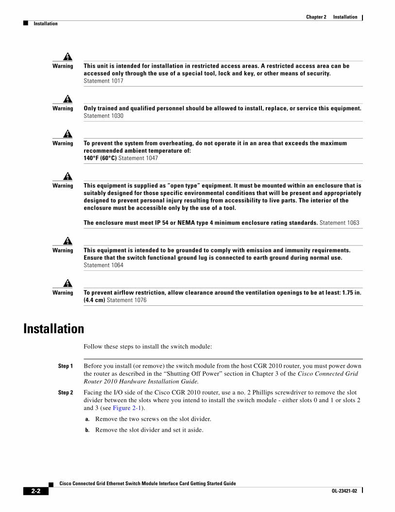
Step 2 Facing the I/O side of the Cisco CGR 2010 router, use a no. 2 Phillips screwdriver to remove the slot divider between the slots where you intend to install the switch module - either slots 0 and 1 or slots 2 and 3 (see Figure 2-1).
a. Remove the two screws on the slot divider.
b. Remove the slot divider and set it aside.
2-2Cisco Connected Grid Ethernet Switch Module Interface Card Getting Started Guide
OL-23421-02
Chapter 2 InstallationInstallation
Figure 2-1 Removing the Slot Divider From the CGR 2010 Router
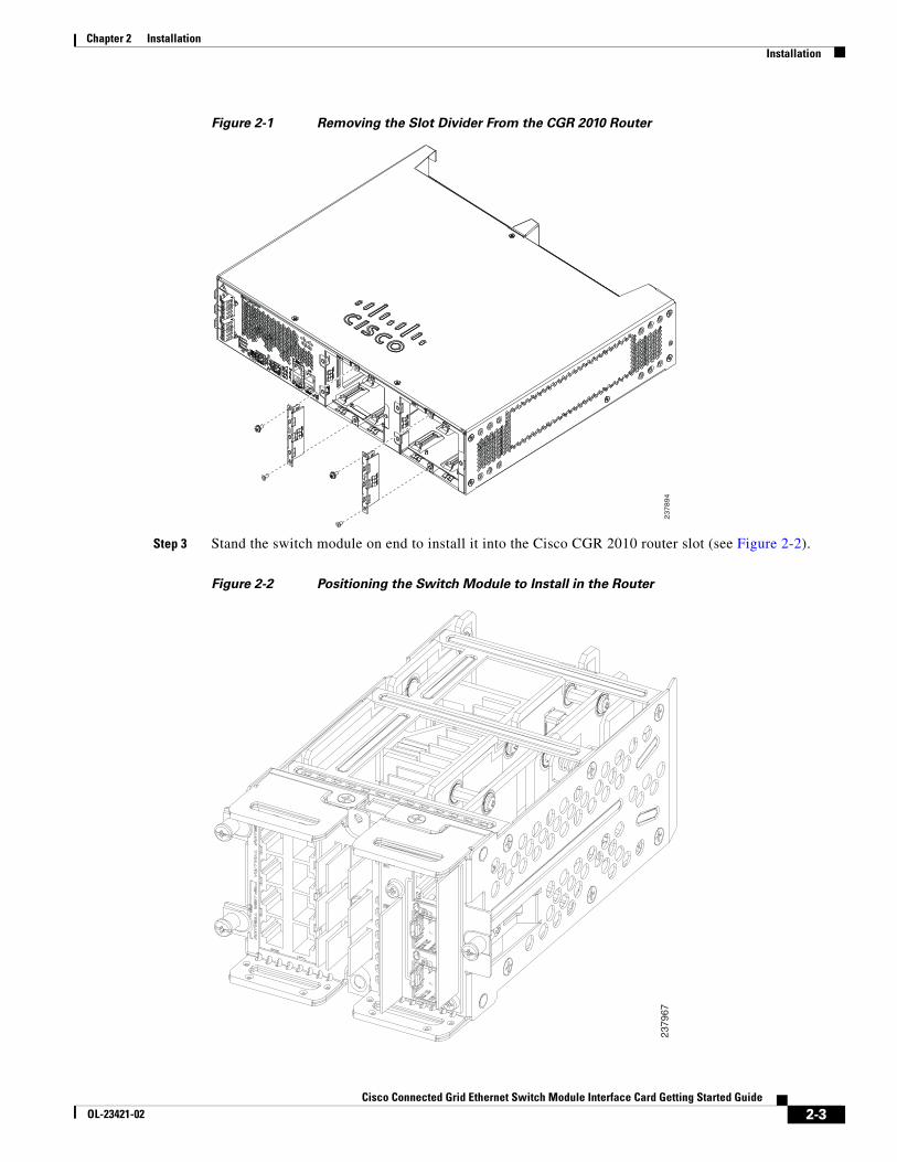
Step 3 Stand the switch module on end to install it into the Cisco CGR 2010 router slot (see Figure 2-2).
Figure 2-2 Positioning the Switch Module to Install in the Router
23
78
94
2379
67
2-3Cisco Connected Grid Ethernet Switch Module Interface Card Getting Started Guide
OL-23421-02
Chapter 2 InstallationInstallation
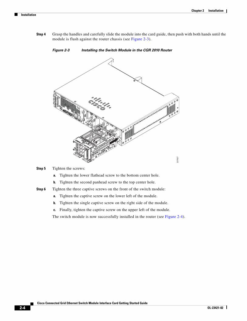
Step 4 Grasp the handles and carefully slide the module into the card guide, then push with both hands until the module is flush against the router chassis (see Figure 2-3).
Figure 2-3 Installing the Switch Module in the CGR 2010 Router
Step 5 Tighten the screws:
a. Tighten the lower flathead screw to the bottom center hole.
b. Tighten the second panhead screw to the top center hole.
Step 6 Tighten the three captive screws on the front of the switch module:
a. Tighten the captive screw on the lower left of the module.
b. Tighten the single captive screw on the right side of the module.
c. Finally, tighten the captive screw on the upper left of the module.
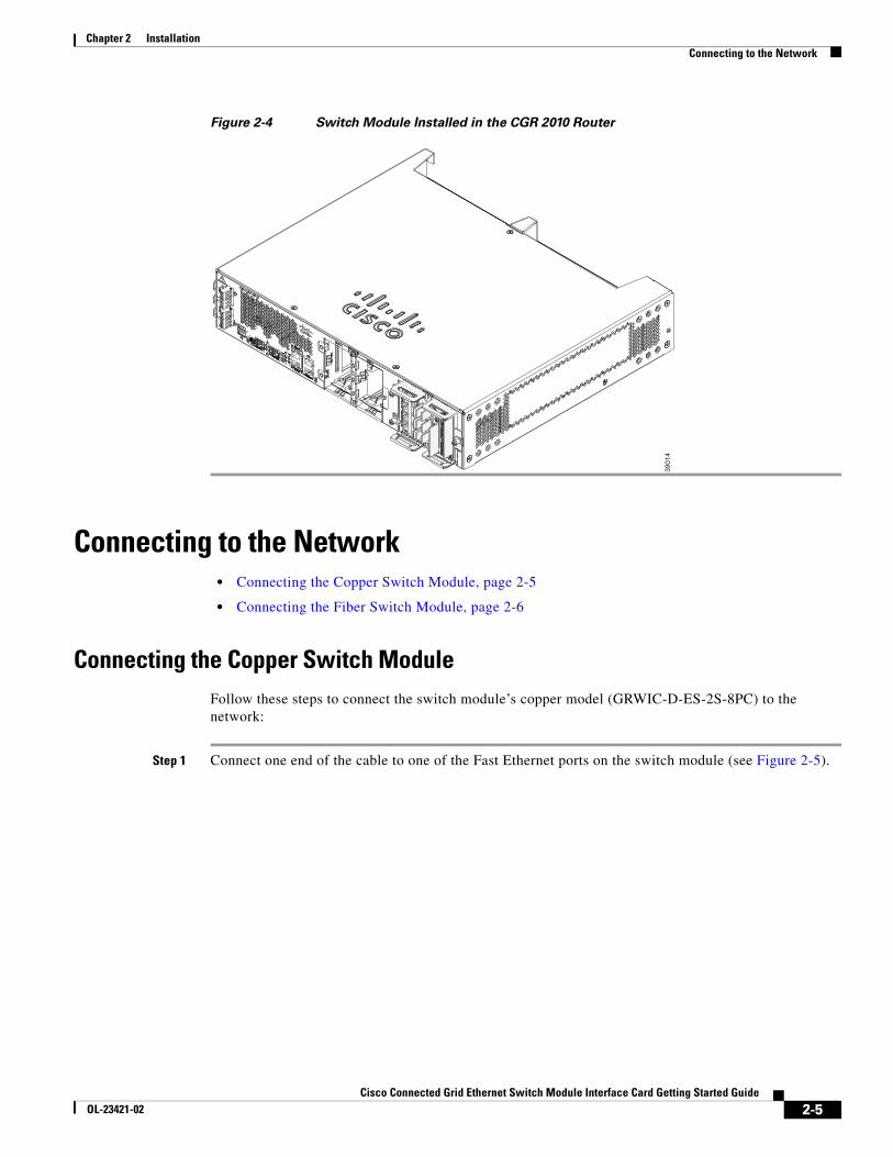
The switch module is now successfully installed in the router (see Figure 2-4).
2379
27
2-4Cisco Connected Grid Ethernet Switch Module Interface Card Getting Started Guide
OL-23421-02
Chapter 2 InstallationConnecting to the Network
Figure 2-4 Switch Module Installed in the CGR 2010 Router
Connecting to the Network • Connecting the Copper Switch Module, page 2-5
• Connecting the Fiber Switch Module, page 2-6
Connecting the Copper Switch ModuleFollow these steps to connect the switch module’s copper model (GRWIC-D-ES-2S-8PC) to the network:
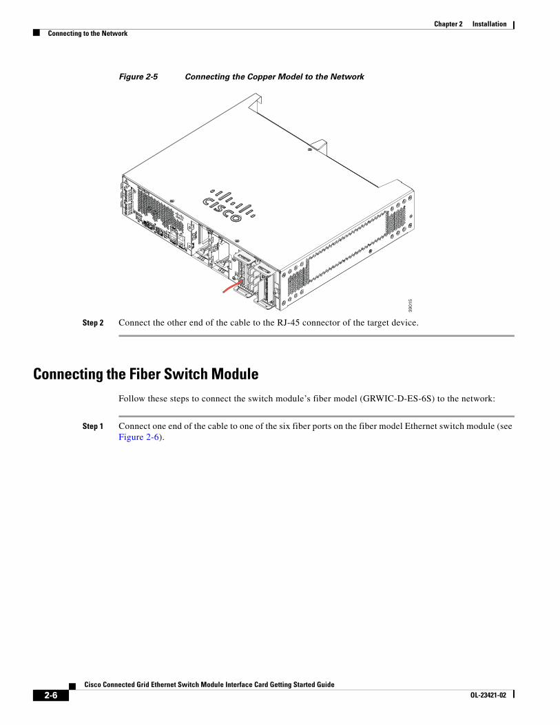
Step 1 Connect one end of the cable to one of the Fast Ethernet ports on the switch module (see Figure 2-5).
2390
14
2-5Cisco Connected Grid Ethernet Switch Module Interface Card Getting Started Guide
OL-23421-02
Chapter 2 InstallationConnecting to the Network
Figure 2-5 Connecting the Copper Model to the Network
Step 2 Connect the other end of the cable to the RJ-45 connector of the target device.
Connecting the Fiber Switch ModuleFollow these steps to connect the switch module’s fiber model (GRWIC-D-ES-6S) to the network:
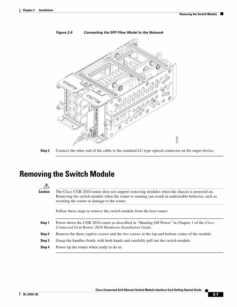
Step 1 Connect one end of the cable to one of the six fiber ports on the fiber model Ethernet switch module (see Figure 2-6).
23
90
15
2-6Cisco Connected Grid Ethernet Switch Module Interface Card Getting Started Guide
OL-23421-02
Chapter 2 InstallationRemoving the Switch Module
Figure 2-6 Connecting the SFP Fiber Model to the Network
Step 2 Connect the other end of the cable to the standard LC-type optical connector on the target device.
Removing the Switch Module
Caution The Cisco CGR 2010 router does not support removing modules when the chassis is powered on. Removing the switch module when the router is running can result in undesirable behavior, such as resetting the router or damage to the router.
Follow these steps to remove the switch module from the host router:
Step 1 Power down the CGR 2010 router as described in “Shutting Off Power” in Chapter 3 of the Cisco Connected Grid Router 2010 Hardware Installation Guide.
Step 2 Remove the three captive screws and the two screws at the top and bottom center of the module.
Step 3 Grasp the handles firmly with both hands and carefully pull out the switch module.
Step 4 Power up the router when ready to do so.
2379
42
2-7Cisco Connected Grid Ethernet Switch Module Interface Card Getting Started Guide
OL-23421-02

Chapter 2 InstallationRemoving the Switch Module
2-8Cisco Connected Grid Ethernet Switch Module Interface Card Getting Started Guide
OL-23421-02
Cisco Connected Grid Ethernet SOL-23421-02
C H A P T E R 3
Express SetupYou access the switch module via the host CGR 2010 router. For more information, see Accessing the Switch Module, page 4-2.
To exchange and monitor control messages between the switch module and the router, a Router Blade Configuration Protocol (RBCP) stack operates concurrently on active IOS sessions running on both the host router and the switch module.
You should use Express Setup to enter the initial IP information. You can then access the switch module through the IP address for further configuration.
This chapter contains the following topics:
• System Requirements
• Express Setup
• Troubleshooting Express Setup
• Resetting the Switch Module
Note To use the CLI-based initial setup program, see Appendix A, “Creating an Initial Configuration with the CLI Setup Program,” in the Cisco Connected Grid Ethernet Switch Module Interface Card Software Configuration Guide.
System RequirementsYou need the following software and cables to run Express Setup:
• PC with Windows 2000, XP, Vista, Windows Server 2003, or Windows 7
• Web browser (Internet Explorer 6.0, 7.0, or Firefox 1.5, 2.0, or later) with JavaScript enabled
• Straight-through or crossover Category 5 or Category 6 cable
Express Setup Follow these steps to start Express Setup:
Step 1 Disable any pop-up blockers or proxy settings on your web browser, and any wireless client running on your computer.
3-1witch Module Interface Card Getting Started Guide
Chapter 3 Express SetupExpress Setup
Step 2 Verify that no device is connected to the switch module.
Step 3 Temporarily configure your computer to use DHCP, if it has a static IP address. The switch module acts as a DHCP server.
Tip Write down the static IP address, as you need this address in a later step.
Step 4 Power on the CGR 2010 router. Once the host router is powered up, the router automatically powers up the switch model.
For more information, see “Powering Up the Router” in Chapter 4, “Configuring the Router,” in the Cisco Connected Grid Routers 2010 Hardware Installation Guide.
Once the switch module powers on, it starts the Power-On Self-Test (POST), which can take up to two minutes.
• During POST, the System LED blinks green and then port LEDs turn green
• When POST is complete, the System LED remains green and the other LEDs turn off
Note If the System LED blinks green, does not turn green or turns amber, the switch module failed POST. Contact your Cisco representative or reseller.
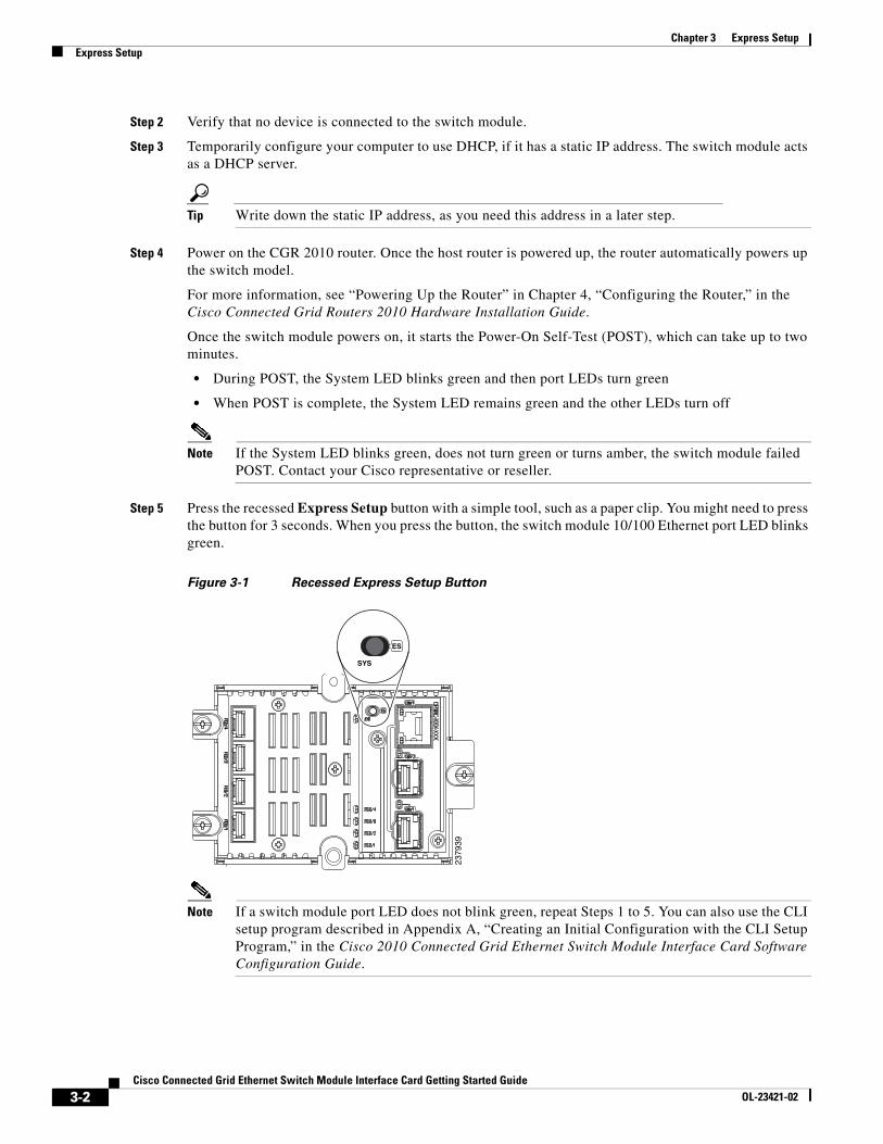
Step 5 Press the recessed Express Setup button with a simple tool, such as a paper clip. You might need to press the button for 3 seconds. When you press the button, the switch module 10/100 Ethernet port LED blinks green.
Figure 3-1 Recessed Express Setup Button
Note If a switch module port LED does not blink green, repeat Steps 1 to 5. You can also use the CLI setup program described in Appendix A, “Creating an Initial Configuration with the CLI Setup Program,” in the Cisco 2010 Connected Grid Ethernet Switch Module Interface Card Software Configuration Guide.
2379
39
ES
SYS
3-2Cisco Connected Grid Ethernet Switch Module Interface Card Getting Started Guide
OL-23421-02
Chapter 3 Express SetupExpress Setup
Step 6 Select one of the following:
• For the Copper Model (GRWIC-D-ES-2S-8PC), connect a Cat 5 or 6 cable to the blinking 10/100BASE-T port, and the plug the other end to the Ethernet port on your computer
• For the SFP Fiber Model (GRWIC-D-ES-6S), connect a Category 5 or Category 6 cable to the 100/1000BASE-T port of the dual-purpose port (GE0/1), and then plug the other end to the Ethernet plug on your computer
Wait until the port LEDs on the switch module and your computer are either green or blinking green (indicates successful connection).
Tip If the port LEDs are not green after 30 seconds, verify you are using Cat 5 or 6 cable and that the cable is not damaged. Make sure the other devices are turned on. You can also verify the connection by pinging IP address 169.250.0.1.
Follow these steps to configure the switch module:
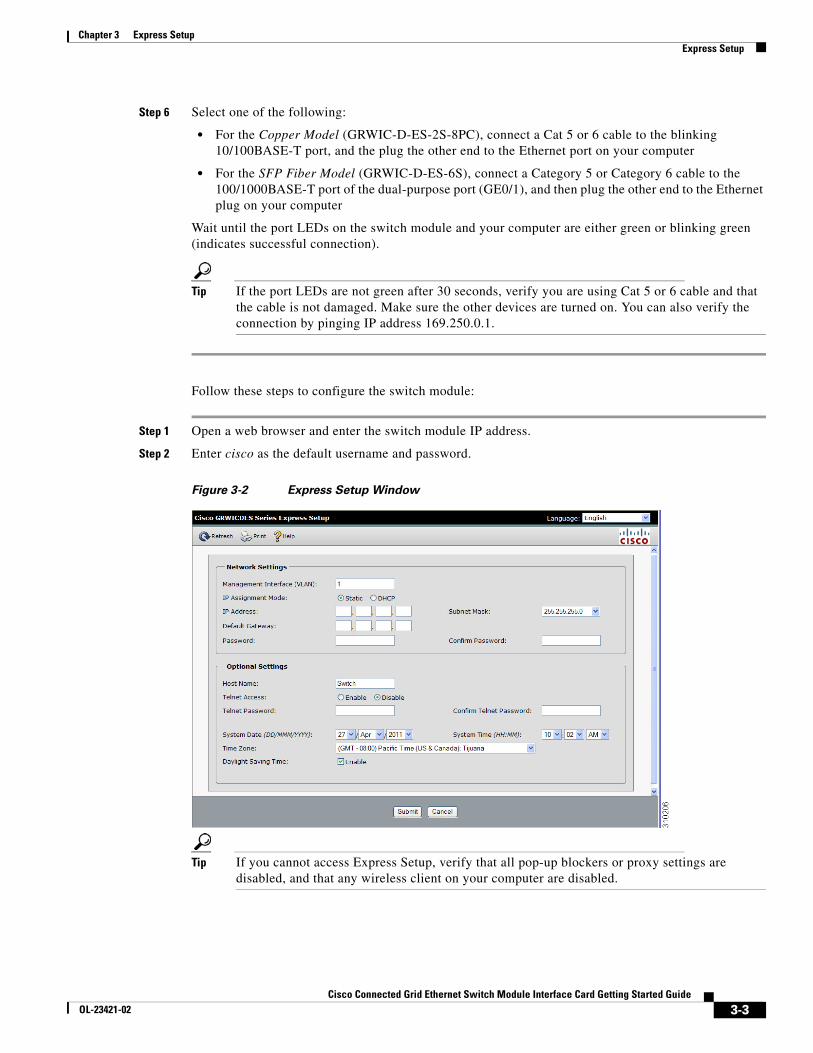
Step 1 Open a web browser and enter the switch module IP address.
Step 2 Enter cisco as the default username and password.
Figure 3-2 Express Setup Window
Tip If you cannot access Express Setup, verify that all pop-up blockers or proxy settings are disabled, and that any wireless client on your computer are disabled.
3-3Cisco Connected Grid Ethernet Switch Module Interface Card Getting Started Guide
OL-23421-02
Chapter 3 Express SetupExpress Setup
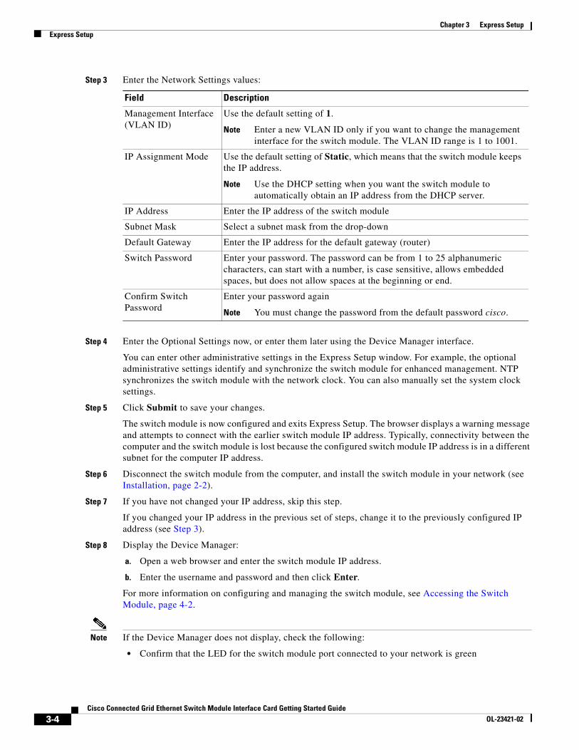
Step 3 Enter the Network Settings values:
Step 4 Enter the Optional Settings now, or enter them later using the Device Manager interface.
You can enter other administrative settings in the Express Setup window. For example, the optional administrative settings identify and synchronize the switch module for enhanced management. NTP synchronizes the switch module with the network clock. You can also manually set the system clock settings.
Step 5 Click Submit to save your changes.
The switch module is now configured and exits Express Setup. The browser displays a warning message and attempts to connect with the earlier switch module IP address. Typically, connectivity between the computer and the switch module is lost because the configured switch module IP address is in a different subnet for the computer IP address.
Step 6 Disconnect the switch module from the computer, and install the switch module in your network (see Installation, page 2-2).
Step 7 If you have not changed your IP address, skip this step.
If you changed your IP address in the previous set of steps, change it to the previously configured IP address (see Step 3).
Step 8 Display the Device Manager:
a. Open a web browser and enter the switch module IP address.
b. Enter the username and password and then click Enter.
For more information on configuring and managing the switch module, see Accessing the Switch Module, page 4-2.
Note If the Device Manager does not display, check the following:
• Confirm that the LED for the switch module port connected to your network is green
Field Description
Management Interface (VLAN ID)
Use the default setting of 1.
Note Enter a new VLAN ID only if you want to change the management interface for the switch module. The VLAN ID range is 1 to 1001.
IP Assignment Mode Use the default setting of Static, which means that the switch module keeps the IP address.
Note Use the DHCP setting when you want the switch module to automatically obtain an IP address from the DHCP server.
IP Address Enter the IP address of the switch module
Subnet Mask Select a subnet mask from the drop-down
Default Gateway Enter the IP address for the default gateway (router)
Switch Password Enter your password. The password can be from 1 to 25 alphanumeric characters, can start with a number, is case sensitive, allows embedded spaces, but does not allow spaces at the beginning or end.
Confirm Switch Password
Enter your password again
Note You must change the password from the default password cisco.
3-4Cisco Connected Grid Ethernet Switch Module Interface Card Getting Started Guide
OL-23421-02
Chapter 3 Express SetupTroubleshooting Express Setup
• Confirm that the computer that you are using to access the switch module has network connectivity by connecting to a web server in your network. If there is no network connection, troubleshoot the network settings on your computer.
• Verify that the switch module IP address in the browser is correct. If it is correct, the port LED is green and the computer has network connectivity. Continue troubleshooting by disconnecting and then reconnecting the switch module to your computer. Configure a static IP address on the computer that is in the same subnet as the switch module IP address.
When the LED on the switch module port that connects to the computer is green, open a web browser and enter the switch module IP address to display the Device Manager. When the Device Manager displays, you can continue with configuration.
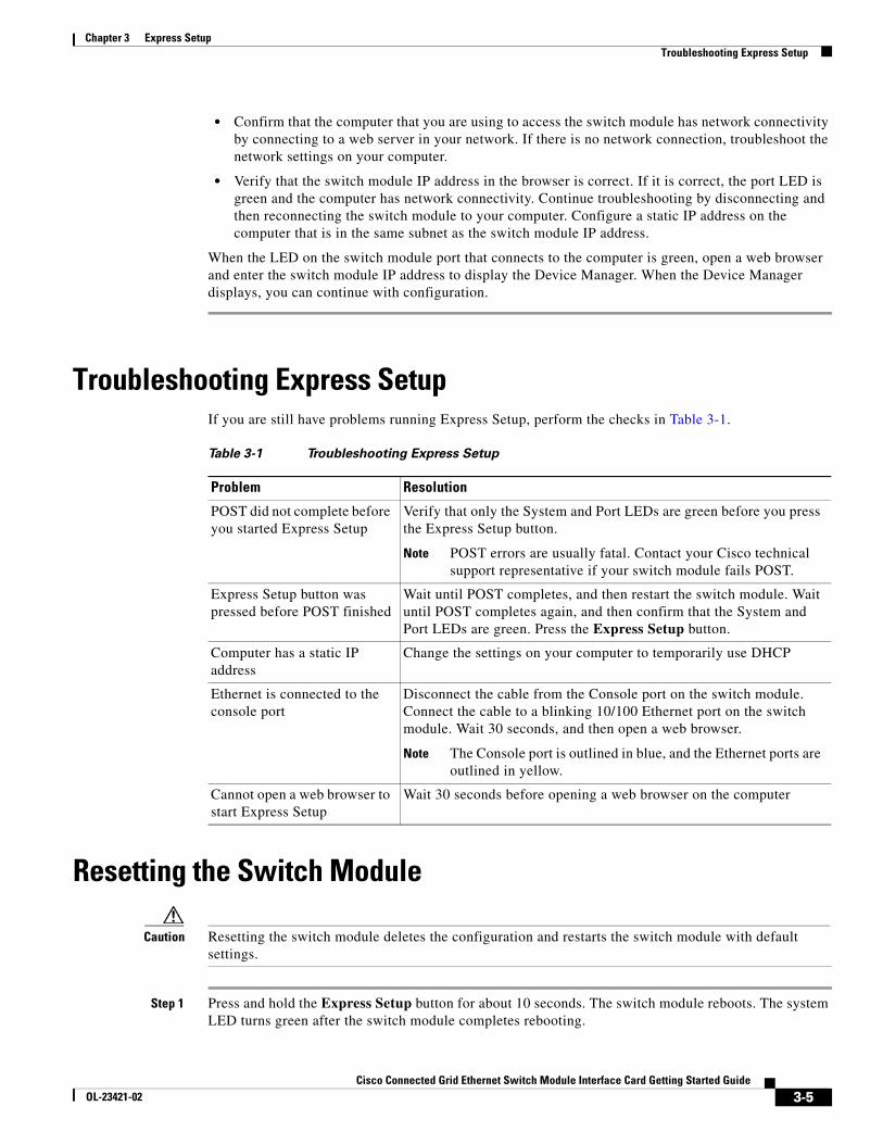
Troubleshooting Express SetupIf you are still have problems running Express Setup, perform the checks in Table 3-1.
Resetting the Switch Module
Caution Resetting the switch module deletes the configuration and restarts the switch module with default settings.
Step 1 Press and hold the Express Setup button for about 10 seconds. The switch module reboots. The system LED turns green after the switch module completes rebooting.
Table 3-1 Troubleshooting Express Setup
Problem Resolution
POST did not complete before you started Express Setup
Verify that only the System and Port LEDs are green before you press the Express Setup button.
Note POST errors are usually fatal. Contact your Cisco technical support representative if your switch module fails POST.
Express Setup button was pressed before POST finished
Wait until POST completes, and then restart the switch module. Wait until POST completes again, and then confirm that the System and Port LEDs are green. Press the Express Setup button.
Computer has a static IP address
Change the settings on your computer to temporarily use DHCP
Ethernet is connected to the console port
Disconnect the cable from the Console port on the switch module. Connect the cable to a blinking 10/100 Ethernet port on the switch module. Wait 30 seconds, and then open a web browser.
Note The Console port is outlined in blue, and the Ethernet ports are outlined in yellow.
Cannot open a web browser to start Express Setup
Wait 30 seconds before opening a web browser on the computer
3-5Cisco Connected Grid Ethernet Switch Module Interface Card Getting Started Guide
OL-23421-02
Chapter 3 Express SetupResetting the Switch Module
Step 2 Press the Express Setup button again for three seconds. The switch module 10/100 Ethernet port LED blinks green.
Step 3 Follow the steps in Express Setup, page 3-1.
3-6Cisco Connected Grid Ethernet Switch Module Interface Card Getting Started Guide
OL-23421-02
Cisco Connected Grid Ethernet SOL-23421-02
C H A P T E R 4
Managing the Switch ModuleAfter completing Express Setup and installing the switch module in your network, you can use these options for further configuration:
• Using the Device Manager
• Cisco Configuration Professional
• Other Management Options
• Accessing the Switch Module, page 4-2
• Connecting Devices to the Switch Module, page 4-4
Using the Device ManagerThe simplest way to manage the switch module is with the Device Manager in the switch module memory. This web interface offers quick configuration. You can access the device manager from anywhere in your network through a web browser.
Follow these steps to use the Device Manager:
Step 1 Open a web browser, enter the switch module IP address, and then press Enter.
Step 2 Use the Device Manager for basic switch module configuration. See the Device Manager online help for more information.
Cisco Configuration ProfessionalCisco Configuration Professional (CCP) is a software program that you can download from Cisco.com and run on your PC. It offers advanced options for configuring and monitoring multiple devices, including the switch module. Configuration Professional is free—there is no charge to download, install, or use it.
Follow these steps to use CCP:
Step 1 Go to this URL: http://www.cisco.com/en/US/products/ps9422/index.html
4-1witch Module Interface Card Getting Started Guide
Chapter 4 Managing the Switch ModuleOther Management Options
Note You must be a registered Cisco.com user, but you need no other access privileges.
Step 2 Click Download Software.
Step 3 Select the latest release of the Configuration Professional installer, and click Download.
Note Cisco Configuration Professional 2.5 or later is supported on the switch module.
Step 4 Run the Configuration Professional installer, and follow the directions.
Step 5 Click Finish to complete the installation.
See the Configuration Professional Getting Started Guide and online help for more information.
Other Management OptionsYou can use SNMP management applications such as CiscoWorks LAN Management Solution (LMS) and Cisco netManager to configure and manage the switch module. You also can manage the switch module from an SNMP-compatible workstation that is running platforms such as Cisco netManager or SunNet Manager.
The Cisco Configuration Engine is a network management device that works with embedded Cisco Networking Services (CNS) agents in the switch software. You can use it to automate initial configurations and configuration updates on the switch.
Accessing the Switch Module
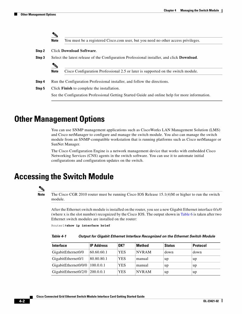
Note The Cisco CGR 2010 router must be running Cisco IOS Release 15.1(4)M or higher to run the switch module.
After the Ethernet switch module is installed on the router, you see a new Gigabit Ethernet interface 0/x/0 (where x is the slot number) recognized by the Cisco IOS. The output shown in Table 6 is taken after two Ethernet switch modules are installed on the router:
Router1#show ip interface brief
Table 4-1 Output for Gigabit Ethernet Interface Recognized on the Ethernet Switch Module
Interface IP Address OK? Method Status Protocol
GigabitEthernet0/0 60.60.60.1 YES NVRAM down down
GigabitEthernet0/1 80.80.80.1 YES manual up up
GigabitEthernet0/0/0 100.0.0.1 YES manual up up
GigabitEthernet0/2/0 200.0.0.1 YES NVRAM up up
4-2Cisco Connected Grid Ethernet Switch Module Interface Card Getting Started Guide
OL-23421-02
Chapter 4 Managing the Switch ModuleAccessing the Switch Module
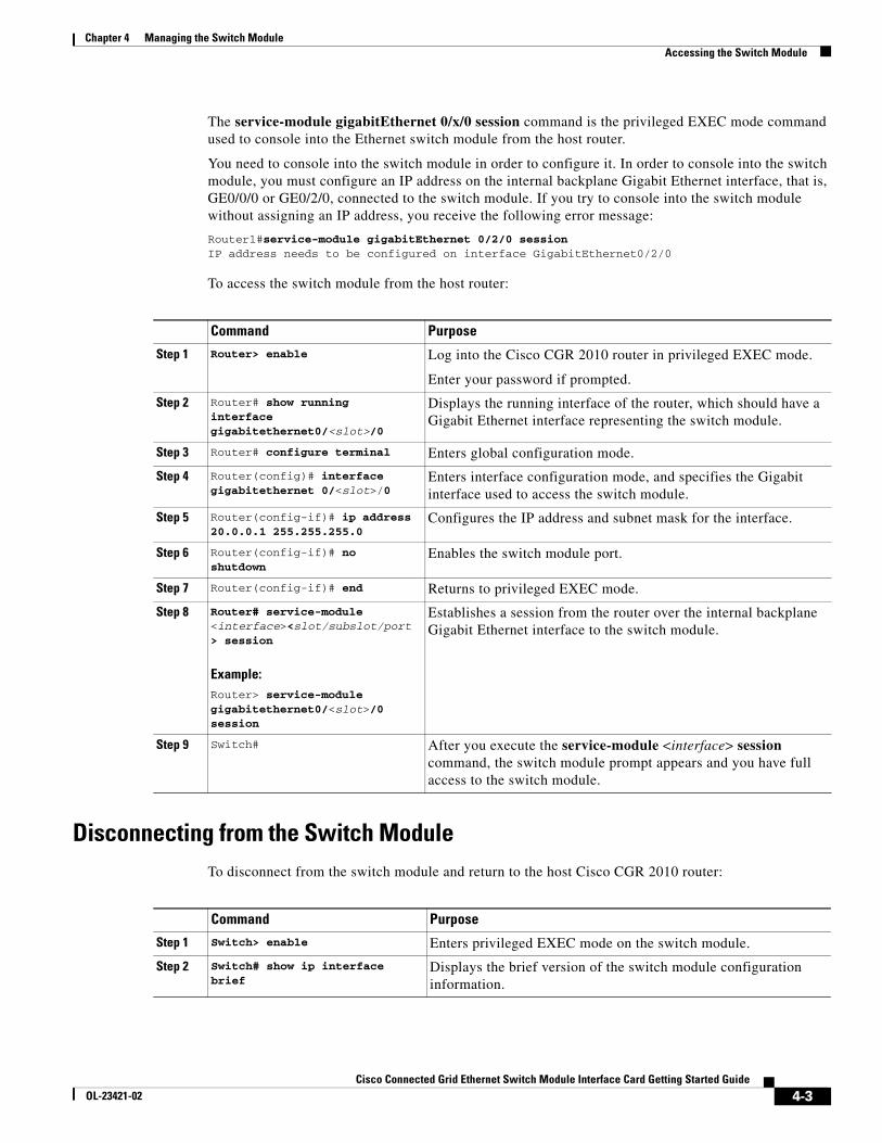
The service-module gigabitEthernet 0/x/0 session command is the privileged EXEC mode command used to console into the Ethernet switch module from the host router.
You need to console into the switch module in order to configure it. In order to console into the switch module, you must configure an IP address on the internal backplane Gigabit Ethernet interface, that is, GE0/0/0 or GE0/2/0, connected to the switch module. If you try to console into the switch module without assigning an IP address, you receive the following error message:
Router1#service-module gigabitEthernet 0/2/0 session IP address needs to be configured on interface GigabitEthernet0/2/0
To access the switch module from the host router:
Disconnecting from the Switch ModuleTo disconnect from the switch module and return to the host Cisco CGR 2010 router:
Command Purpose
Step 1 Router> enable Log into the Cisco CGR 2010 router in privileged EXEC mode.
Enter your password if prompted.
Step 2 Router# show running interface gigabitethernet0/<slot>/0
Displays the running interface of the router, which should have a Gigabit Ethernet interface representing the switch module.
Step 3 Router# configure terminal Enters global configuration mode.
Step 4 Router(config)# interface gigabitethernet 0/<slot>/0
Enters interface configuration mode, and specifies the Gigabit interface used to access the switch module.
Step 5 Router(config-if)# ip address 20.0.0.1 255.255.255.0
Configures the IP address and subnet mask for the interface.
Step 6 Router(config-if)# no shutdown
Enables the switch module port.
Step 7 Router(config-if)# end Returns to privileged EXEC mode.
Step 8 Router# service-module <interface><slot/subslot/port> session
Example:Router> service-module gigabitethernet0/<slot>/0 session
Establishes a session from the router over the internal backplane Gigabit Ethernet interface to the switch module.
Step 9 Switch# After you execute the service-module <interface> session command, the switch module prompt appears and you have full access to the switch module.
Command Purpose
Step 1 Switch> enable Enters privileged EXEC mode on the switch module.
Step 2 Switch# show ip interface brief
Displays the brief version of the switch module configuration information.
4-3Cisco Connected Grid Ethernet Switch Module Interface Card Getting Started Guide
OL-23421-02
Chapter 4 Managing the Switch ModuleConnecting Devices to the Switch Module
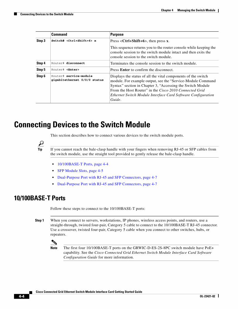
Connecting Devices to the Switch ModuleThis section describes how to connect various devices to the switch module ports.
Tip If you cannot reach the bale-clasp handle with your fingers when removing RJ-45 or SFP cables from the switch module, use the straight tool provided to gently release the bale-clasp handle.
• 10/100BASE-T Ports, page 4-4
• SFP Module Slots, page 4-5
• Dual-Purpose Port with RJ-45 and SFP Connectors, page 4-7
• Dual-Purpose Port with RJ-45 and SFP Connectors, page 4-7
10/100BASE-T PortsFollow these steps to connect to the 10/100BASE-T ports:
Step 1 When you connect to servers, workstations, IP phones, wireless access points, and routers, use a straight-through, twisted four-pair, Category 5 cable to connect to the 10/100BASE-T RJ-45 connector. Use a crossover, twisted four-pair, Category 5 cable when you connect to other switches, hubs, or repeaters.
Note The first four 10/100BASE-T ports on the GRWIC-D-ES-2S-8PC switch module have PoE+ capability. See the Cisco Connected Grid Ethernet Switch Module Interface Card Software Configuration Guide for more information.
Step 3 Switch# <Ctrl+Shift+6> x Press <Ctrl+Shift+6>, then press x.
This sequence returns you to the router console while keeping the console session to the switch module intact and then exits the console session to the switch module.
Step 4 Router# disconnect Terminates the console session to the switch module.
Step 5 Router# <Enter> Press Enter to confirm the disconnect.
Step 6 Router# service-module gigabitethernet 0/0/0 status
Displays the status of all the vital components of the switch module. For example output, see the “Service-Module Command Syntax” section in Chapter 3, “Accessing the Switch Module From the Host Router” in the Cisco 2010 Connected Grid Ethernet Switch Module Interface Card Software Configuration Guide.
Command Purpose
4-4Cisco Connected Grid Ethernet Switch Module Interface Card Getting Started Guide
OL-23421-02
Chapter 4 Managing the Switch ModuleConnecting Devices to the Switch Module
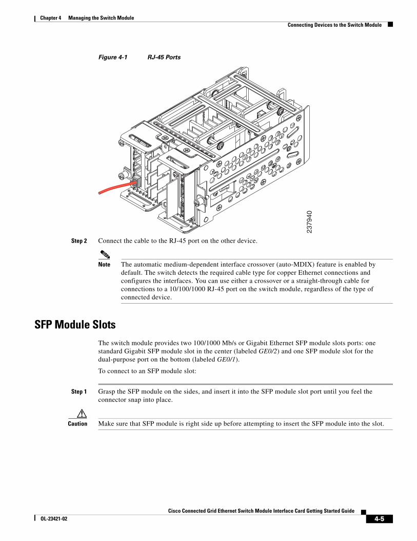
Figure 4-1 RJ-45 Ports
Step 2 Connect the cable to the RJ-45 port on the other device.
Note The automatic medium-dependent interface crossover (auto-MDIX) feature is enabled by default. The switch detects the required cable type for copper Ethernet connections and configures the interfaces. You can use either a crossover or a straight-through cable for connections to a 10/100/1000 RJ-45 port on the switch module, regardless of the type of connected device.
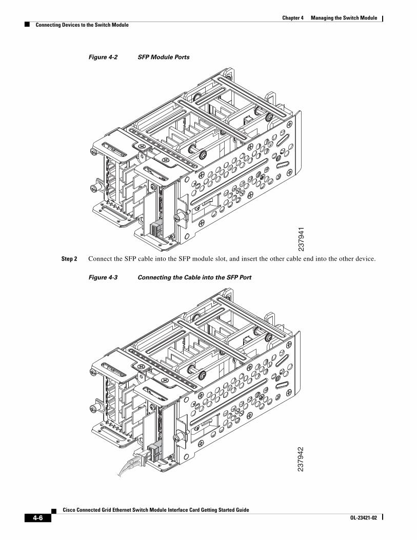
SFP Module SlotsThe switch module provides two 100/1000 Mb/s or Gigabit Ethernet SFP module slots ports: one standard Gigabit SFP module slot in the center (labeled GE0/2) and one SFP module slot for the dual-purpose port on the bottom (labeled GE0/1).
To connect to an SFP module slot:
Step 1 Grasp the SFP module on the sides, and insert it into the SFP module slot port until you feel the connector snap into place.
Caution Make sure that SFP module is right side up before attempting to insert the SFP module into the slot.
2379
40
4-5Cisco Connected Grid Ethernet Switch Module Interface Card Getting Started Guide
OL-23421-02
Chapter 4 Managing the Switch ModuleConnecting Devices to the Switch Module
Figure 4-2 SFP Module Ports
Step 2 Connect the SFP cable into the SFP module slot, and insert the other cable end into the other device.
Figure 4-3 Connecting the Cable into the SFP Port
2379
4123
7942
4-6Cisco Connected Grid Ethernet Switch Module Interface Card Getting Started Guide
OL-23421-02
Chapter 4 Managing the Switch ModuleConnecting Devices to the Switch Module
For detailed instructions on installing, removing, and connecting to SFP modules, see the SFP module documentation.
Dual-Purpose Port with RJ-45 and SFP ConnectorsThe Gigabit Ethernet port GE0/1 on the switch module consists of a pair of one RJ-45 connector (topmost port) and one SFP module connector (bottom port).
This dual-purpose port is considered as a single interface. The two connectors are not redundant interfaces—the switch module activates only one connector of the pair at a time.
If the dual-purpose port is configured as media-type RJ-45, the speed of the connection can be manually set to either 10, 100 or 1000 Mb/s (10/100/1000BASE-T specifications). The default speed setting is always enabled to AUTONEGOTIATION. It will automatically negotiate to whatever speed is set on the other end of the connection.
If the dual-purpose port is configured as media-type SFP, the speed is dependent on the module type you are using, either a 100FX or a 1000BASE-X SFP module. The port will automatically detect the module, and the speed is set based on the media type. The other end of the connection will have to be of the same media type in order to establish the link.
Note Even when operating at 100 Mb/s, the dual-purpose ports (and the SFP-only module slots) use the frame size that is set with the system mtu jumbo global configuration command.
By default, the dual-purpose ports and the SFP-only module slots are network node interfaces (NNIs).
By default, the switch module dynamically selects the dual-purpose port media type that first links up. However, you can use the media-type interface configuration command to manually select the RJ-45 connector or the SFP module slot.
Note In auto-select mode, if both copper and fiber-optic signals are simultaneously detected, the switch module gives preference to SFP mode.
For configuration information, see “Configuring a Dual-Purpose Port” in Chapter 8, “Configuring Interfaces,” in the Cisco 2010 Connected Grid Ethernet Switch Module Interface Card Software Configuration Guide.
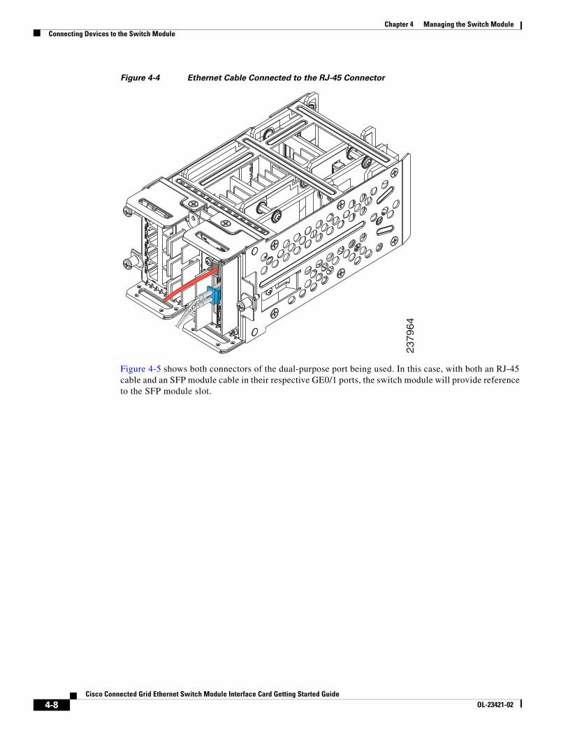
The following illustration shows an Ethernet cable connected to the RJ-45 connector of the dual-purpose port (GE0/1). It also shows an SFP cable connected to the standard SFP module slot (GE0/2).
4-7Cisco Connected Grid Ethernet Switch Module Interface Card Getting Started Guide
OL-23421-02
Chapter 4 Managing the Switch ModuleConnecting Devices to the Switch Module
Figure 4-4 Ethernet Cable Connected to the RJ-45 Connector
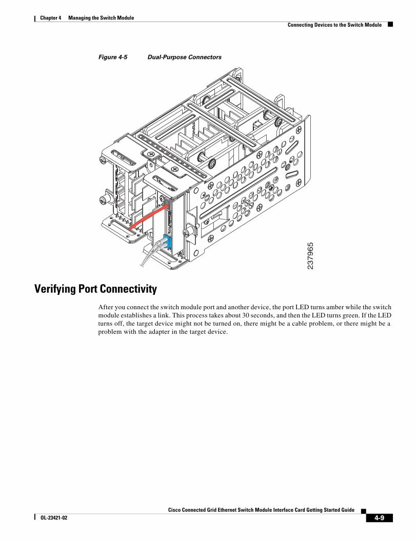
Figure 4-5 shows both connectors of the dual-purpose port being used. In this case, with both an RJ-45 cable and an SFP module cable in their respective GE0/1 ports, the switch module will provide reference to the SFP module slot.
237964
4-8Cisco Connected Grid Ethernet Switch Module Interface Card Getting Started Guide
OL-23421-02
Chapter 4 Managing the Switch ModuleConnecting Devices to the Switch Module
Figure 4-5 Dual-Purpose Connectors
Verifying Port ConnectivityAfter you connect the switch module port and another device, the port LED turns amber while the switch module establishes a link. This process takes about 30 seconds, and then the LED turns green. If the LED turns off, the target device might not be turned on, there might be a cable problem, or there might be a problem with the adapter in the target device.
23
79
65
4-9Cisco Connected Grid Ethernet Switch Module Interface Card Getting Started Guide
OL-23421-02

Chapter 4 Managing the Switch ModuleConnecting Devices to the Switch Module
4-10Cisco Connected Grid Ethernet Switch Module Interface Card Getting Started Guide
OL-23421-02
Cisco Connected Grid Ethernet Switch OL-23421-02
A
P P E N D I X A Cable and Connectors• Connector Specifications, page A-1
• Cables and Adapters, page A-2
Connector Specifications • 10/100BASE-T Ports, page A-1
• SFP Module Connectors, page A-1
• Dual-Purpose Ports, page A-2
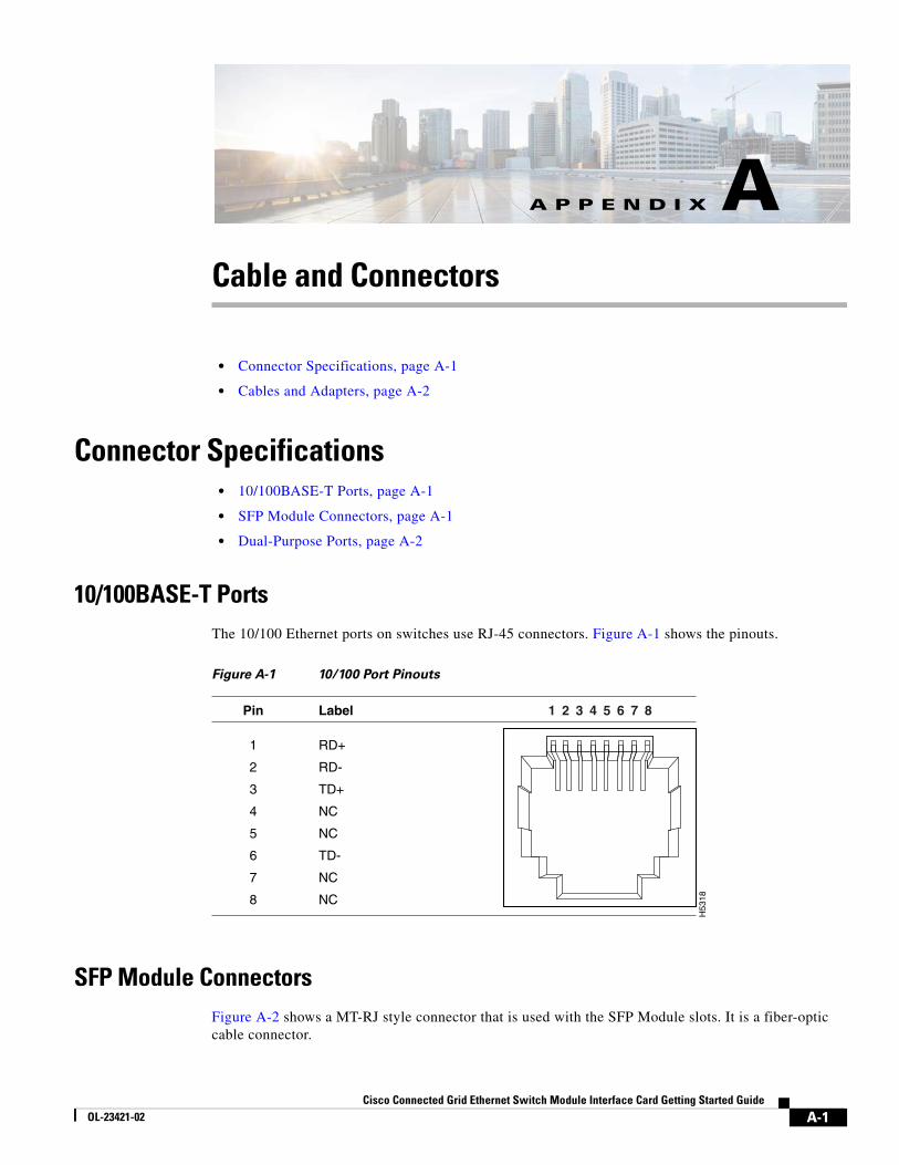
10/100BASE-T PortsThe 10/100 Ethernet ports on switches use RJ-45 connectors. Figure A-1 shows the pinouts.
Figure A-1 10/100 Port Pinouts
SFP Module ConnectorsFigure A-2 shows a MT-RJ style connector that is used with the SFP Module slots. It is a fiber-optic cable connector.
H53
182 31 4 5 6 7 8Pin Label
1
2
3
4
5
6
7
8
RD+
RD-
TD+
NC
NC
TD-
NC
NC
A-1Module Interface Card Getting Started Guide
Appendix A Cable and ConnectorsCables and Adapters
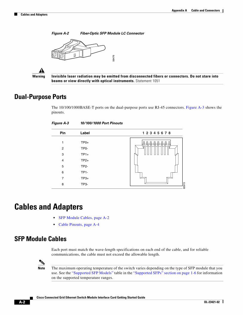
Figure A-2 Fiber-Optic SFP Module LC Connector
Warning Invisible laser radiation may be emitted from disconnected fibers or connectors. Do not stare into beams or view directly with optical instruments. Statement 1051
Dual-Purpose PortsThe 10/100/1000BASE-T ports on the dual-purpose ports use RJ-45 connectors. Figure A-3 shows the pinouts.
Figure A-3 10/100/1000 Port Pinouts
Cables and Adapters • SFP Module Cables, page A-2
• Cable Pinouts, page A-4
SFP Module Cables Each port must match the wave-length specifications on each end of the cable, and for reliable communications, the cable must not exceed the allowable length.
Note The maximum operating temperature of the switch varies depending on the type of SFP module that you use. See the “Supported SFP Models” table in the “Supported SFPs” section on page 1-6 for information on the supported temperature ranges.
5847
6
6091
5
2 31 4 5 6 7 8Pin Label
1
2
3
4
5
6
7
8
TP0+
TP0-
TP1+
TP2+
TP2-
TP1-
TP3+
TP3-
A-2Cisco Connected Grid Ethernet Switch Module Interface Card Getting Started Guide
OL-23421-02
Appendix A Cable and ConnectorsCables and Adapters
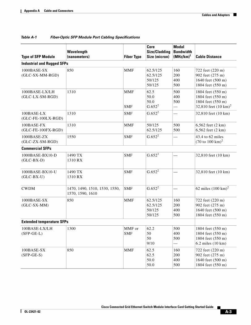
Table A-1 Fiber-Optic SFP Module Port Cabling Specifications
Type of SFP ModuleWavelength (nanometers) Fiber Type
Core Size/Cladding Size (micron)
Modal Bandwidth (MHz/km)1 Cable Distance
Industrial and Rugged SFPs
1000BASE-SX (GLC-SX-MM-RGD)
850 MMF 62.5/125 62.5/125 50/125 50/125
160 200 400 500
722 feet (220 m) 902 feet (275 m) 1640 feet (500 m) 1804 feet (550 m)
1000BASE-LX/LH (GLC-LX-SM-RGD)
1310 MMF SMF
62.5 50.0 50.0 G.6522
500 400 500 —
1804 feet (550 m) 1804 feet (550 m) 1804 feet (550 m) 32,810 feet (10 km)2
100BASE-LX (GLC-FE-100LX-RGD)
1310 SMF G.6522 — 32,810 feet (10 km)
100BASE-FX (GLC-FE-100FX-RGD)
1310 MMF 50/125 62.5/125
500 500
6,562 feet (2 km) 6,562 feet (2 km)
1000BASE-ZX (GLC-ZX-SM-RGD)
1550 SMF G.6522 — 43.4 to 62 miles (70 to 100 km)2
Commercial SFPs
1000BASE-BX10-D (GLC-BX-D)
1490 TX 1310 RX
SMF G.6523 — 32,810 feet (10 km)
1000BASE-BX10-U (GLC-BX-U)
1490 TX 1310 RX
SMF G.6522 — 32,810 feet (10 km)
CWDM 1470, 1490, 1510, 1530, 1550, 1570, 1590, 1610
SMF G.6522 — 62 miles (100 km)2
1000BASE-SX (GLC-SX-MM)
850 MMF 62.5/125 62.5/125 50/125 50/125
160 200 400 500
722 feet (220 m) 902 feet (275 m) 1640 feet (500 m) 1804 feet (550 m)
Extended temperature SFPs
100BASE-LX/LH (SFP-GE-L)
1300 MMF or SMF
62.2 50 50 9/10
500 400 500 —
1804 feet (550 m) 1804 feet (550 m) 1804 feet (550 m) 6.2 miles (10 km)
100BASE-SX (SFP-GE-S)
850 MMF 62.5 62.5 50.0 50.0
160 200 400 500
722 feet (220 m) 902 feet (275 m) 1640 feet (500 m) 1804 feet (550 m)
A-3Cisco Connected Grid Ethernet Switch Module Interface Card Getting Started Guide
OL-23421-02
Appendix A Cable and ConnectorsCables and Adapters
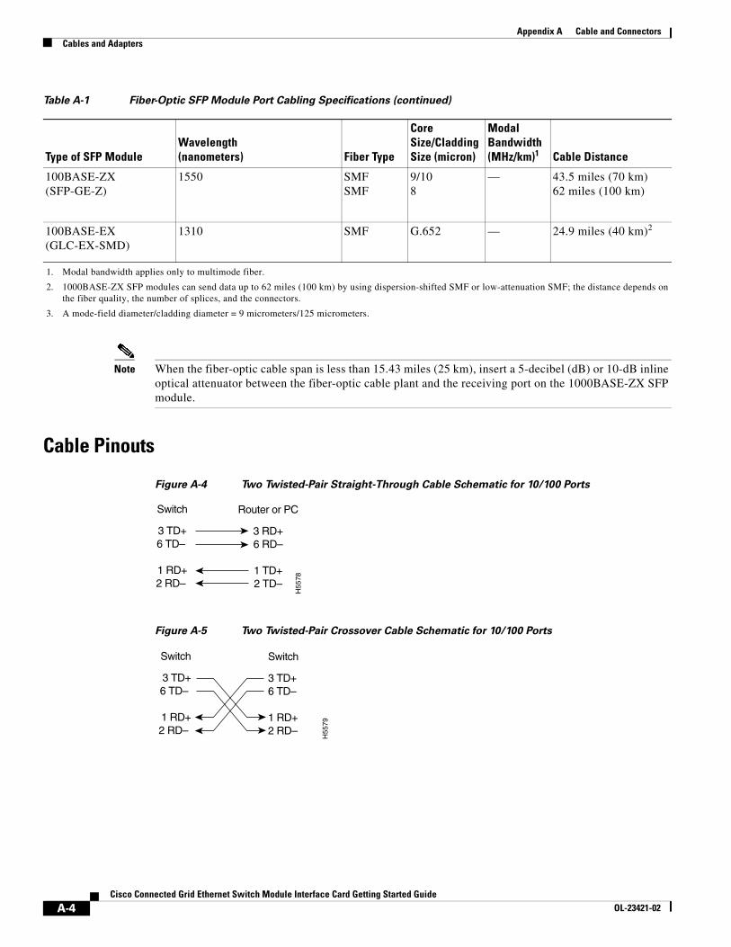
Note When the fiber-optic cable span is less than 15.43 miles (25 km), insert a 5-decibel (dB) or 10-dB inline optical attenuator between the fiber-optic cable plant and the receiving port on the 1000BASE-ZX SFP module.
Cable Pinouts
Figure A-4 Two Twisted-Pair Straight-Through Cable Schematic for 10/100 Ports
Figure A-5 Two Twisted-Pair Crossover Cable Schematic for 10/100 Ports
100BASE-ZX (SFP-GE-Z)
1550 SMF SMF
9/10 8
— 43.5 miles (70 km) 62 miles (100 km)
100BASE-EX (GLC-EX-SMD)
1310 SMF G.652 — 24.9 miles (40 km)2
1. Modal bandwidth applies only to multimode fiber.
2. 1000BASE-ZX SFP modules can send data up to 62 miles (100 km) by using dispersion-shifted SMF or low-attenuation SMF; the distance depends on the fiber quality, the number of splices, and the connectors.
3. A mode-field diameter/cladding diameter = 9 micrometers/125 micrometers.
Table A-1 Fiber-Optic SFP Module Port Cabling Specifications (continued)
Type of SFP ModuleWavelength (nanometers) Fiber Type
Core Size/Cladding Size (micron)
Modal Bandwidth (MHz/km)1 Cable Distance
Switch
3 TD+6 TD–
1 RD+2 RD–
Router or PC
3 RD+6 RD–
1 TD+2 TD–
H55
78
Switch
3 TD+6 TD–
1 RD+2 RD–
Switch
3 TD+6 TD–
1 RD+2 RD–
H55
79
A-4Cisco Connected Grid Ethernet Switch Module Interface Card Getting Started Guide
OL-23421-02
Appendix A Cable and ConnectorsCables and Adapters
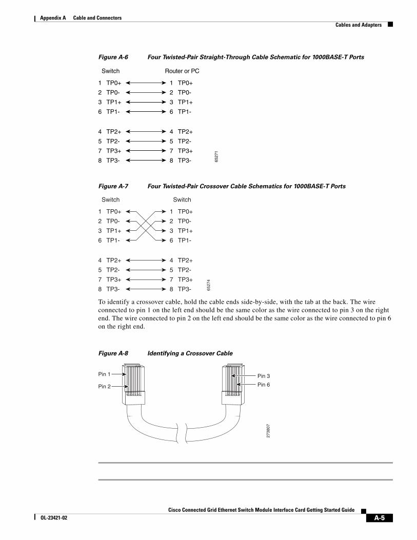
Figure A-6 Four Twisted-Pair Straight-Through Cable Schematic for 1000BASE-T Ports
Figure A-7 Four Twisted-Pair Crossover Cable Schematics for 1000BASE-T Ports
To identify a crossover cable, hold the cable ends side-by-side, with the tab at the back. The wire connected to pin 1 on the left end should be the same color as the wire connected to pin 3 on the right end. The wire connected to pin 2 on the left end should be the same color as the wire connected to pin 6 on the right end.
Figure A-8 Identifying a Crossover Cable
1 TP0+
2 TP0-
3 TP1+
6 TP1-
1 TP0+
2 TP0-
3 TP1+
6 TP1-
Switch Router or PC
4 TP2+
5 TP2-
7 TP3+
8 TP3-
4 TP2+
5 TP2-
7 TP3+
8 TP3- 6527
11 TP0+
2 TP0-
3 TP1+
6 TP1-
1 TP0+
Switch Switch
2 TP0-
3 TP1+
6 TP1-
4 TP2+
5 TP2-
7 TP3+
8 TP3-
4 TP2+
5 TP2-
7 TP3+
8 TP3- 6527
4
Pin 1
Pin 2
2738
07
Pin 6
Pin 3
A-5Cisco Connected Grid Ethernet Switch Module Interface Card Getting Started Guide
OL-23421-02

Appendix A Cable and ConnectorsCables and Adapters
A-6Cisco Connected Grid Ethernet Switch Module Interface Card Getting Started Guide
OL-23421-02