
Cisco CAD Installation Guide/Cisco Unified Contact Center ...
164
Americas Headquarters Cisco Systems, Inc. 170 West Tasman Drive San Jose, CA 95134-1706 USA http://www.cisco.com Tel: 408 526-4000 800 553-NETS (6387) Fax: 408 527-0883 Cisco CAD Installation Guide Cisco Unified Contact Center Enterprise and Hosted Release 9.0 First Published: July 2012 Last Modified: August 4, 2014
Transcript of Cisco CAD Installation Guide/Cisco Unified Contact Center ...

Cisco CAD Installation GuideCisco Unified Contact Center Enterprise and Hosted Release 9.0
First Published: July 2012Last Modified: August 4, 2014
Americas HeadquartersCisco Systems, Inc.170 West Tasman DriveSan Jose, CA 95134-1706 USAhttp://www.cisco.comTel: 408 526-4000
800 553-NETS (6387)Fax: 408 527-0883

THE SPECIFICATIONS AND INFORMATION REGARDING THE PRODUCTS IN THIS MANUAL ARE SUBJECT TO CHANGE WITHOUT NOTICE. ALL STATEMENTS, INFORMATION, AND RECOMMENDATIONS IN THIS MANUAL ARE BELIEVED TO BE ACCURATE BUT ARE PRESENTED WITHOUT WARRANTY OF ANY KIND, EXPRESS OR IMPLIED. USERS MUST TAKE FULL RESPONSIBILITY FOR THEIR APPLICATION OF ANY PRODUCTS.
THE SOFTWARE LICENSE AND LIMITED WARRANTY FOR THE ACCOMPANYING PRODUCT ARE SET FORTH IN THE INFORMATION PACKET THAT SHIPPED WITH THE PRODUCT AND ARE INCORPORATED HEREIN BY THIS REFERENCE. IF YOU ARE UNABLE TO LOCATE THE SOFTWARE LICENSE OR LIMITED WARRANTY, CONTACT YOUR CISCO REPRESENTATIVE FOR A COPY.
The Cisco implementation of TCP header compression is an adaptation of a program developed by the University of California, Berkeley (UCB) as part of UCB’s public domain version of the UNIX operating system. All rights reserved. Copyright © 1981, Regents of the University of California.
NOTWITHSTANDING ANY OTHER WARRANTY HEREIN, ALL DOCUMENT FILES AND SOFTWARE OF THESE SUPPLIERS ARE PROVIDED “AS IS” WITH ALL FAULTS. CISCO AND THE ABOVE-NAMED SUPPLIERS DISCLAIM ALL WARRANTIES, EXPRESSED OR IMPLIED, INCLUDING, WITHOUT LIMITATION, THOSE OF MERCHANTABILITY, FITNESS FOR A PARTICULAR PURPOSE AND NONINFRINGEMENT OR ARISING FROM A COURSE OF DEALING, USAGE, OR TRADE PRACTICE.
IN NO EVENT SHALL CISCO OR ITS SUPPLIERS BE LIABLE FOR ANY INDIRECT, SPECIAL, CONSEQUENTIAL, OR INCIDENTAL DAMAGES, INCLUDING, WITHOUT LIMITATION, LOST PROFITS OR LOSS OR DAMAGE TO DATA ARISING OUT OF THE USE OR INABILITY TO USE THIS MANUAL, EVEN IF CISCO OR ITS SUPPLIERS HAVE BEEN ADVISED OF THE POSSIBILITY OF SUCH DAMAGES.
Cisco and the Cisco logo are trademarks or registered trademarks of Cisco and/or its affiliates in the U.S. and other countries. To view a list of Cisco trademarks, go to this URL: www.cisco.com/go/trademarks. Third-party trademarks mentioned are the property of their respective owners. The use of the word partner does not imply a partnership relationship between Cisco and any other company. (1110R)
Any Internet Protocol (IP) addresses and phone numbers used in this document are not intended to be actual addresses and phone numbers. Any examples, command display output, network topology diagrams, and other figures included in the document are shown for illustrative purposes only. Any use of actual IP addresses or phone numbers in illustrative content is unintentional and coincidental.
Cisco CAD Installation Guide© 2012 - 2013 Cisco Systems, Inc. All rights reserved.
Contents
1 Introduction 11
■ Overview 11
Related CAD Documentation 11
Obtaining Documentation and Submitting a Service Request 12
Documentation Feedback 12
■ CAD 9.0 Feature Levels 13
Agent Desktop 13
CAD-BE 14
IP Phone Agent 14
Supervisor Desktop 15
Desktop Administrator 15
■ What’s New in This Version 17
■ CAD 9.0 Components 18
Desktop Applications 18
Desktop Administrator 18
Agent Desktop 18
CAD-BE 18
IP Phone Agent 19
Supervisor Desktop 19
Desktop Monitoring Console 19
Services 19
BIPPA Service 20
Chat Service 20
Directory Services 20
Enterprise Service 20
LDAP Monitor Service 20
LRM Service 21
Recording & Playback Service 21
Recording and Statistics Service 21
Sync Service 21
Tomcat Service 21
VoIP Monitor Service 21
■ Localization 22

Contents
Supported Languages 22
Installation in Localized Contact Centers 23
■ System Capacity 24
2 Requirements 27
■ System Configurations 27
Thin Client Environments 27
■ System Requirements 28
Operating Environment 28
Minimum Hardware and OS Requirements 28
Operating Environment Language Requirements 29
VPN and NAT Requirements 30
Using NAT With IP Phone Agent and CAD-BE 30
Third Party Software Requirements 31
Microsoft Internet Explorer 31
Mozilla Firefox 32
Microsoft SQL Server 2008 R2 Standard or Enterprise Edition 32
OpenLDAP 32
CTI OS 32
Monitoring Requirements 32
■ Supported IP Phones 34
Caveats on Using a Cisco 7920 Wireless Phone 34
3 Before You Install CAD 9.0 35
■ Overview 35
■ Configuring Unified ICM 36
Supervisors and Teams 36
Enterprise Data and Call History 36
Skills Statistics 36
Reason Codes 37
Contents
■ Configuring Non-ACD Call (Multi-line) Settings 38
Call Display 38
Call Monitoring and Recording 39
Call Barge-in and Intercept 39
■ Preparing User Accounts and Permissions 40
■ Configuring Microsoft SQL Server 2008 R2 for CAD 9.0 41
SQL Server in a High Availability Configuration 41
Modifying the Database Size Limit 42
Installing and Configuring SQL Server 2008 R2 42
Upgrading from SQL Server 2005 52
Upgrading from CAD 7.6 53
Upgrading from CAD 8.0 or 8.5 53
4 Installing CAD 9.0 55
■ Overview 55
Installing CAD Base Services 56
CAD Configuration Setup Utility 60
Configuring a Primary Server in a Replicated System 62
CAD Configuration Setup Utility Nodes 64
Unified CM SOAP AXL Access 64
Unified Communications Manager 66
CTI Server (Unified CM) 68
CTI OS 70
ICM Admin Workstation Distributor 71
ICM Admin Workstation Database 73
Recording and Statistics Database Configuration 75
Recording and Statistics Service Database 78
Restore Backup Data 80
CAD-BE Servers 81
VoIP Monitor Service 83
Services Configuration 84
SNMP Configuration 86
Contents
Thin Client Environment 88
Replication 89
Configuring a Secondary Server in a Replicated System 91
Modifying Configuration Settings 92
■ Licensing CAD 9.0 94
Obtaining a License Account 94
Using Unified CCE License Administration 95
Recording Licenses 96
■ Modifying the Peripheral Gateway Registry 97
5 CAD Desktop Client Applications 99
■ Configuring CAD Client MSI Files 99
Overview 99
Client MSI Preparation Procedure for Base Releases 100
Client MSIs for Maintenance Releases and Engineering Specials 101
■ Using Automated Package Distribution Tools 103
Requirements 103
Execution 103
Per-Machine vs. Per-User Installation 103
Privileges 103
Automated Package Installation vs. Manual Installation 104
Multiple Software Releases 104
Reboots 104
Best Practices 104
Windows Installer Logging 104
Deployment 105
Installation and Uninstallation Deployment Packages 105
Recommended Deployment Preparation Model 105
■ Installing Desktop Applications 106
Client Installation Failure 106
Error/Event and Debug Logs 107
Installing Desktop Administrator 107
Contents
Installing Agent Desktop and Supervisor Desktop 107
Installation Notes 107
Configuring CAD-BE 108
Internet Explorer Settings for CAD-BE 108
Firefox Settings for CAD-BE 109
6 Upgrading from a Previous Version of CAD 111
■ Overview 111
Upgrade Notes 112
Upgrading Replicated Systems 113
■ Upgrade Methods 114
Backup and Restore Upgrade Method Overview 115
Over the Top Upgrade Method Overview 117
■ Upgrading from CAD 7.5/7.6, CAD 8.0, and CAD 8.5 (Windows Server 2003) 119
Going from Flat Files to SQL Server 2008 R2 119
Going from MSDE or SQL Server 2005 to SQL Server 2008 R2 120
■ Upgrading from 8.5 (Windows Server 2008 R2) 123
Going from Flat Files to Flat Files 123
Going from Flat Files to SQL Server 2008 R2 123
Going from SQL Server 2005 to SQL Server 2008 R2 125
■ Backup and Restore 126
Backup File Location 126
Backing Up CAD Data 126
Restoring CAD Data 127
BackupDB Utility 128
InstallRestoreDB Utility 129
CDBRTool Utility 131
Backup and Restore Notes 132
■ Rolling Back CAD 9.0 to an Earlier Version of CAD 133
Rollback Notes 133
■ Changing Feature Levels in an Upgrade 134
Contents
■ Installing a Maintenance Release or Engineering Special 135
Engineering Test (ET) 135
Engineering Special (ES) 135
Maintenance Release (MR) 135
MR, ES, and ET Guidelines 135
Removing Patches 136
Upgrading to 9.0(3) 137
■ Upgrading CAD Desktop Clients 138
7 Additional Considerations 139
■ Switching Data Stores 139
Overview 139
Switching From Flat Files to SQL Server Database 139
Preparing for Switching Data Stores 139
Using the Data Migration Tool 140
■ Configuring IP Phones for IP Phone Agent 142
Creating an IP Phone Service 142
Assigning the IP Phone Service to IP Agent Phones 143
Configuring IP Phones for Use with a Localized BIPPA Service 144
Creating a Unified CM User 145
Changing the Default Authentication URL 146
Configuring a One-Button Login for IP Phone Agents 147
■ Configuring an IP Communicator Phone 148
■ Setting Up CTI OS Security 149
Steps to Perform on Each Element 149
CTI OS Server 149
Desktop Work Flow Administrator PC 149
Agent Desktop Client PCs 150
Certificate PC 150
Signing Client CTI OS Security Certificates 151
Signing the Server CTI OS Security Certificate 151
Signing a Peer CTI OS Server Security Certificate 152
Contents
CTI OS Security Setup 152
■ Desktop Monitoring Console 153
Configuring Microsoft SNMP Service for use with CAD 153
Configuring Cisco SNMP Agent Management Service for use with CAD 154
■ Repairing CAD 156
■ Shutting Down and Restarting Replication 157
Shutting Down Replication 158
Restarting Replication 159
■ Reinstalling CAD Services in a High Availability System 161
8 Removal 163
■ Removing CAD 9.0 163
Removing MRs, ESs, and ETs 163

Contents
August 4, 2014
Introduction
Overview
Installing CAD 9.0 consists of the following tasks:
1. Verify that software and hardware requirements are met. For instructions, see Chapter 2, "Requirements".
2. Complete the preinstallation preparations. For instructions, see Chapter 3, "Before You Install CAD 9.0".
3. Install and configure the CAD services in accordance with your installation scenario. For more information, see Chapter 4, "Installing CAD 9.0".
4. Install the CAD desktop client applications. For more information, see Chapter 5, "CAD Desktop Client Applications".
5. Configure miscellaneous system components. For more information, see Chapter 7, "Additional Considerations".
After you have completed these steps, the basic functionality of CAD is ready to use with no further configuration required.
Related CAD Documentation
The following documents contain additional information about CAD 9.0:
■ Cisco Agent Desktop User Guide
■ Cisco Agent Desktop—Browser Edition User Guide
■ Cisco Supervisor Desktop User Guide
■ Cisco IP Phone Agent User Guide
■ Cisco Desktop Administrator User Guide
■ Mobile Agent Guide for Cisco Unified CC Enterprise
■ Cisco CAD Troubleshooting Guide
■ Integrating CAD with Thin Client and Virtual Desktop Environments
11
Cisco CAD Installation Guide
Obtaining Documentation and Submitting a Service Request
For information on obtaining documentation, submitting a service request, and gathering additional information, see the monthly What’s New in Cisco Product Documentation, which also lists all new and revised Cisco technical documentation, at:
http://www.cisco.com/en/US/docs/general/whatsnew/whatsnew.html
Subscribe to the What’s New in Cisco Product Documentation as a Really Simple Syndication (RSS) feed and set content to be delivered directly to your desktop using a reader application. The RSS feeds are a free service and Cisco currently supports RSS version 2.0.
Documentation Feedback
You can provide comments about this document by sending email to the following address:
We appreciate your comments.
12 August 4, 2014
CAD 9.0 Feature Levels
CAD 9.0 Feature Levels
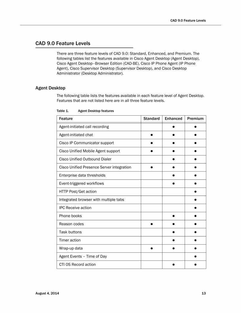
There are three feature levels of CAD 9.0: Standard, Enhanced, and Premium. The following tables list the features available in Cisco Agent Desktop (Agent Desktop), Cisco Agent Desktop–Browser Edition (CAD-BE), Cisco IP Phone Agent (IP Phone Agent), Cisco Supervisor Desktop (Supervisor Desktop), and Cisco Desktop Administrator (Desktop Administrator).
Agent Desktop
The following table lists the features available in each feature level of Agent Desktop. Features that are not listed here are in all three feature levels.
Table 1. Agent Desktop features
Feature Standard Enhanced Premium
Agent-initiated call recording ● ●
Agent-initiated chat ● ● ●
Cisco IP Communicator support ● ● ●
Cisco Unified Mobile Agent support ● ● ●
Cisco Unified Outbound Dialer ● ●
Cisco Unified Presence Server integration ● ● ●
Enterprise data thresholds ● ●
Event-triggered workflows ● ●
HTTP Post/Get action ●
Integrated browser with multiple tabs ●
IPC Receive action ●
Phone books ● ●
Reason codes ● ● ●
Task buttons ● ●
Timer action ● ●
Wrap-up data ● ● ●
Agent Events – Time of Day ●
CTI OS Record action ● ●
August 4, 2014 13
Cisco CAD Installation Guide
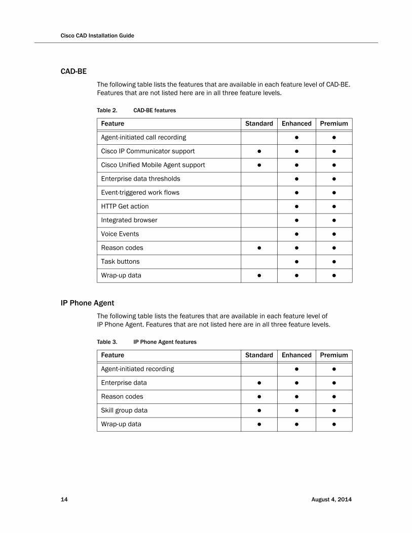
CAD-BE
The following table lists the features that are available in each feature level of CAD-BE. Features that are not listed here are in all three feature levels.
Table 2. CAD-BE features
Feature Standard Enhanced Premium
Agent-initiated call recording ● ●
Cisco IP Communicator support ● ● ●
Cisco Unified Mobile Agent support ● ● ●
Enterprise data thresholds ● ●
Event-triggered work flows ● ●
HTTP Get action ● ●
Integrated browser ● ●
Voice Events ● ●
Reason codes ● ● ●
Task buttons ● ●
Wrap-up data ● ● ●
IP Phone Agent
The following table lists the features that are available in each feature level of IP Phone Agent. Features that are not listed here are in all three feature levels.
Table 3. IP Phone Agent features
Feature Standard Enhanced Premium
Agent-initiated recording ● ●
Enterprise data ● ● ●
Reason codes ● ● ●
Skill group data ● ● ●
Wrap-up data ● ● ●
14 August 4, 2014
CAD 9.0 Feature Levels
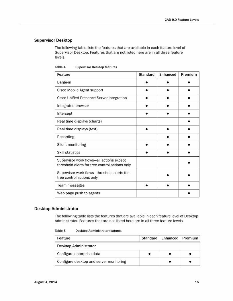
Supervisor Desktop
The following table lists the features that are available in each feature level of Supervisor Desktop. Features that are not listed here are in all three feature levels.
Table 4. Supervisor Desktop features
Feature Standard Enhanced Premium
Barge-in ● ● ●
Cisco Mobile Agent support ● ● ●
Cisco Unified Presence Server integration ● ● ●
Integrated browser ● ● ●
Intercept ● ● ●
Real time displays (charts) ●
Real time displays (text) ● ● ●
Recording ● ●
Silent monitoring ● ● ●
Skill statistics ● ● ●
Supervisor work flows—all actions except threshold alerts for tree control actions only
●
Supervisor work flows—threshold alerts for tree control actions only
● ●
Team messages ● ● ●
Web page push to agents ●
Desktop Administrator
The following table lists the features that are available in each feature level of Desktop Administrator. Features that are not listed here are in all three feature levels.
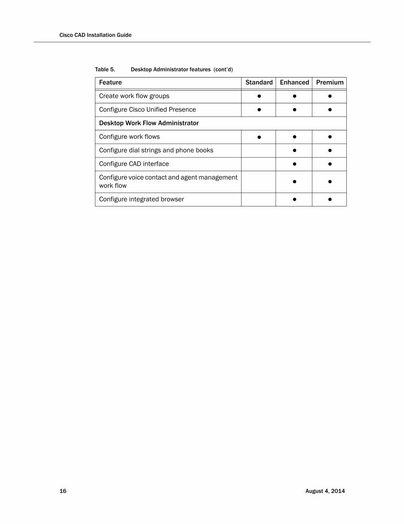
Table 5. Desktop Administrator features
Feature Standard Enhanced Premium
Desktop Administrator
Configure enterprise data ● ● ●
Configure desktop and server monitoring ● ●
August 4, 2014 15
Cisco CAD Installation Guide
Create work flow groups ● ● ●
Configure Cisco Unified Presence ● ● ●
Desktop Work Flow Administrator
Configure work flows ● ● ●
Configure dial strings and phone books ● ●
Configure CAD interface ● ●
Configure voice contact and agent management work flow
● ●
Configure integrated browser ● ●
Table 5. Desktop Administrator features (cont’d)
Feature Standard Enhanced Premium
16 August 4, 2014

What’s New in This Version
What’s New in This Version
CAD 9.0 includes the following new features:
Release 9.0(1a)
■ Support for Cisco AnyConnect Secure Mobility Client Release 3.0
■ Support for JRE 1.6.0, Update 31, for CAD-BE
■ Support for Microsoft SQL Server 2008 R2 (64-bit)
■ Support for precision queues
Release 9.0(3)
■ Support for Call Manager 9.1(1)
■ Bug fixes
■ New guidance on data store alternatives
August 4, 2014 17
Cisco CAD Installation Guide
CAD 9.0 Components
CAD 9.0 is a suite of applications and services consisting of the following elements.
Desktop Applications
Desktop Administrator
Desktop Administrator provides centralized administration tools to configure the desktop applications. It supports multiple administrators, each able to configure the same data (although not at the same time; only one person can work in one node at any one time to ensure data integrity).
See the Cisco Desktop Administrator User Guide for more information.
Agent Desktop
Agent Desktop is an application that provides agents with call control capabilities, such as call answer, hold, conference, and transfer, as well as ACD state control (ready/not ready, wrap-up, etc.). Agent Desktop helps agents manage their customer contacts by presenting customer information to the agents through an enterprise data window, which includes enterprise data, call activity information, and reports. Agent Desktop provides a chat client for chatting with other agents and supervisors and an integrated browser window so agents can view intranet, internet, and web application pages as needed. Agents can use a hard IP phone or the IP Communicator soft phone with Agent Desktop.
Agent Desktop controls the telephony activities on the agent's Cisco Unified Communications Manager (Unified CM) phone line. Agent Desktop cannot coexist with other applications that attempt to share or control the agent's Unified CM phone line, such as Attendant Console and Unified Personal Communicator.
See the Cisco Agent Desktop User Guide for more information.
CAD-BE
CAD-BE is a Java applet version of Agent Desktop that runs in Internet Explorer and Mozilla Firefox web browsers.
CAD-BE is an application that provides agents with call control capabilities, such as call answer, hold, conference, and transfer, as well as ACD state control (ready/not ready, wrap-up, etc.). CAD-BE helps agents manage their customer contacts by presenting customer information to the agents through an enterprise data window, which includes enterprise data, call activity information, and reports. CAD-BE also provides an integrated browser window so agents can view intranet, internet, and web application pages as needed.
See the Cisco Agent Desktop—Browser Edition User Guide for more information.
18 August 4, 2014
CAD 9.0 Components
IP Phone Agent
IP Phone Agent is a service that runs on the agent’s IP phone that enables agents to manage their customer contacts without requiring the use of a computer. IP Phone Agent includes enterprise data, agent states, wrap-up data, reason codes, and skill statistics. See the Cisco IP Phone Agent User Guide for more information.
Supervisor Desktop
Supervisor Desktop allows contact center supervisors to manage agent teams in real time. They can observe, coach, and view agent status details, as well as view conference information. Without the caller’s knowledge, supervisors can initiate chat sessions with agents to help them handle calls, and push web pages to the agent to assist the agent in serving the customer. They can also silently monitor and record customer calls and, if necessary, conference in or take over those calls using the barge-in and intercept features. Through the Supervisor Record Viewer, supervisors can play back and save recorded agent calls.
Desktop Monitoring Console
The Desktop Monitoring Console is a web servlet that allows you to monitor the status of the CAD services and the LDAP Directory Services. It is installed automatically when the CAD base services are installed. For more information, see "Desktop Monitoring Console" on page 153.
Services
CAD base services are installed on a single server and include the following services:
■ Cisco Browser and IP Phone Agent (BIPPA) Service
■ Cisco Chat Service
■ Cisco Enterprise Service
■ Directory Services
■ Cisco LDAP Monitor Service
■ Cisco Licensing and Resource Manager (LRM) Service
■ Cisco Recording and Statistics Service
■ Cisco Sync Service
■ Tomcat Service
CAD includes two other services that can be installed on the same server as the base services or on different servers. These services are the following:
■ Cisco Recording & Playback Service
■ Cisco VoIP Monitor Service
August 4, 2014 19
Cisco CAD Installation Guide
A set of the base services plus the additional services is a logical contact center, or LCC. For LCC capacities and other CAD system capacities see Table 7 on page 24.
The CAD base services and additional services are described alphabetically below.
BIPPA Service
The BIPPA service enables IP phone agents to log in and out of CTI server, change agent states, and enter wrap-up data and reason codes without using a computer. It also provides these functions to agents who use the browser-based CAD-BE.
This service works in conjunction with the services feature of Unified CM and IP phones.
Chat Service
The Chat service acts as a message broker between the Chat clients and Supervisor Desktop. It is in constant communication with all agent and supervisor desktops.
Agent desktops inform the Chat service of all call activity. The service, in turn, sends this information to all appropriate supervisors. It also facilitates the sending of text chat and team messages between agents (excluding CAD-BE and IP Phone agents) and supervisors.
Directory Services
The LRM service registers with Directory Services at startup. All other services (except the LDAP Monitor service) use the LRM service to determine how to connect to each other.
The majority of the agent, supervisor, team, and skill information is kept in Directory Services. Most of this information is imported from the Cisco Unified Intelligent Contact Management (Unified ICM) logger and kept synchronized by the Sync service. It is also used to hold the configuration information administered via Desktop Administrator.
Enterprise Service
The Enterprise service tracks calls in the system. It is used to attach IVR-collected data to a call in order to make it available at the agent desktop. It also provides real-time call history. The Enterprise service interacts with the CTI server, which typically runs on a peripheral gateway (PG).
LDAP Monitor Service
The LDAP Monitor service starts Directory Services and then monitors the services to ensure that they keep running. It also makes automatic nightly backups of LDAP database and checks the backup to ensure it is valid before archiving it.
20 August 4, 2014

CAD 9.0 Components
LRM Service
The LRM service distributes licenses to clients and oversees the health of the CAD services. In the event of a service failure, it initiates the failover process. All other CAD services, except the LDAP Monitor service, register themselves with the LRM service so that clients can locate them.
Recording & Playback Service
The Recording & Playback service extends the capabilities of the VoIP Monitor service by allowing supervisors and agents to record and play back calls.
Recording and Statistics Service
The Recording and Statistics service maintains a 7-day history of agent and team statistics, such as average time an agent is in a particular agent state, last login time, number of calls an agent has received. It also stores real-time data, which is reset each day at midnight.
Sync Service
The Sync (synchronization) service connects to the Unified ICM Administration Workstation SQL database via an ODBC connection and retrieves agent, supervisor, team, and skill information. It then compares the information with the information in Directory Services and adds, updates, or deletes entries as needed to stay consistent with the Unified ICM configuration.
The Sync service also monitors the Unified ICM LDAP for changes to contact information and contact lists. When this information changes, the Sync service notifies the CAD LDAP of the changes.
Tomcat Service
Tomcat is a Java-based webserver. Tomcat is required for IP Phone Agent to work with the XML pages displayed by IP phones. Tomcat is also used for Desktop Administrator, CAD-BE, Desktop Management Console, and desktop installations.
VoIP Monitor Service
The VoIP (Voice over IP) Monitor service enables supervisors to silently monitor agents. The service accomplishes this by “sniffing” network traffic for voice packets.
NOTE: The VoIP Monitor Service is not used with Unified CM-based monitoring. However, it must be installed and enabled.
Multiple VoIP Monitor services can be installed in one logical contact center to ensure there is enough capacity to handle the number of agents.
August 4, 2014 21

Cisco CAD Installation Guide
Localization
Supported Languages
In CAD 9.0, the CAD desktop applications (except for Desktop Work Flow Administrator, which is available in English only) are localized in the languages displayed in Table 6.
Table 6. Supported languages and CAD desktop application availability
Supported Language CAD CAD-BE CSD IPPA CDA
Chinese—Simplified x x x x*
* IPPA is supported only on phones that have UTF-8 support for this language.
Chinese—Traditional x x x x*
Danish x x x x
Dutch x x x x
English x x x x x
Finnish x x x x
French (Canada) x x x x
French (France) x x x x
German x x x x
Italian x x x x
Japanese x x x x†
Korean x x x x*
Norwegian x x x x
Polish x x x x
Portuguese (Brazil) x x x x
Russian x x x x‡
Spanish x x x x
Swedish x x x x
Turkish x x x x
22 August 4, 2014

Localization
Installation in Localized Contact Centers
The CAD services must be installed on machines running an English language operating system.
The CAD desktop applications can be installed on machines running either an English language or a supported localized language operating system.
Desktop Administrator, although available only in English, must be installed on a machine with a supported localized language operating system in order to be able to create reason codes, wrap-up data, and other communication with agents in the localized language.
† IPPA is partially supported on phones that do not have UTF-8 support for Japanese. On these phones, reason codes and wrap-up data must be Katakana half-width in Shift-JIS format. Kanji is supported only on phones that have UTF-8 support for Japanese.
‡ IPPA is partially supported on phones that do not have UTF-8 support for Russian. On these phones, reason codes and wrap-up data must be ISO-8859-1 without Unicode escapes format.
August 4, 2014 23
Cisco CAD Installation Guide
System Capacity
CAD system capacity depends on the topology and configuration of the Unified CCE system(s), and taking into account the number of agent skill groups and the number of CTI OS instances.
CAD supports up to half of the Max Agent load specified in Table 14, “Sizing Effects Due to Number of Skill Groups/Precision Queues per Agent (8000 Agents)” in the document, Cisco Unified Contact Center Enterprise Solution Reference Network Design (SRND)” and factoring in the effect of multiple CTI OS servers deployed on a single PG.
The SRND is available at:
http://www.cisco.com/en/US/products/sw/custcosw/ps1844/products_implementation_design_guides_list.html
For more information on capacity limitations in systems with multiple CTI OS servers, see the section, “CTI-OS Multi-Server Support” in the SRND.
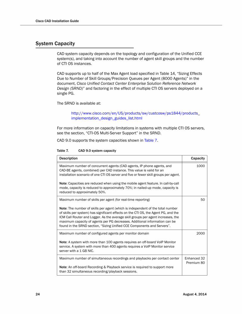
CAD 9.0 supports the system capacities shown in Table 7.
Table 7. CAD 9.0 system capacity
Description Capacity
Maximum number of concurrent agents (CAD agents, IP phone agents, and CAD-BE agents, combined) per CAD instance. This value is valid for an installation scenario of one CTI OS server and five or fewer skill groups per agent.
Note: Capacities are reduced when using the mobile agent feature. In call-by-call mode, capacity is reduced to approximately 70%; in nailed-up mode, capacity is reduced to approximately 50%.
1000
Maximum number of skills per agent (for real-time reporting)
Note: The number of skills per agent (which is independent of the total number of skills per system) has significant effects on the CTI OS, the Agent PG, and the ICM Call Router and Logger. As the average skill groups per agent increases, the maximum capacity of agents per PG decreases. Additional information can be found in the SRND section, “Sizing Unified CCE Components and Servers”.
50
Maximum number of configured agents per monitor domain
Note: A system with more than 100 agents requires an off-board VoIP Monitor service. A system with more than 400 agents requires a VoIP Monitor service server with a 1 GB NIC.
2000
Maximum number of simultaneous recordings and playbacks per contact center
Note: An off-board Recording & Playback service is required to support more than 32 simultaneous recording/playback sessions.
Enhanced 32 Premium 80
24 August 4, 2014

System Capacity
Maximum number of CAD agents per outbound PG
Note: This PG is dedicated to outbound agents coresident with dialer and media routing.
200
Maximum number of off-board Recording & Playback services 2
Maximum number of off-board VoIP Monitor services 5
Maximum number of simultaneous playbacks per Recording and Playback service
8
Maximum number of simultaneous VoIP sessions per VoIP Monitor service 114
Maximum number of simultaneous live supervisor monitoring sessions 58
Table 7. CAD 9.0 system capacity (cont’d)
Description Capacity
August 4, 2014 25

Cisco CAD Installation Guide
26 August 4, 2014
August 4, 2014
Requirements
System Configurations
Supported system configurations are documented in the Cisco Unified Contact Center Enterprise 9.0 Solution Reference Network Design (SRND), available at:
http://www.cisco.com/en/US/products/sw/custcosw/ps1844/products_implementation_design_guides_list.html
Thin Client Environments
CAD is supported in Citrix (XenApp) and Microsoft Terminal Services environments. For more information, see the document, Integrating CAD with Thin Client and Virtual Desktop Environments, available at:
http://www.cisco.com/en/US/products/sw/custcosw/ps1844/tsd_products_support_series_home.html
27
Cisco CAD Installation Guide
System Requirements
CAD 9.0 is integrated into the Unified Contact Center Enterprise and Hosted 9.0 environment.
Consult the following documents for the most current compatibility and requirements information:
■ Cisco Unified Communications Manager Software Compatibility Matrix
■ Cisco Unified Contact Center Enterprise (Unified CCE) Software Compatibility Guide
■ Hardware and System Software Specification (Bill of Materials) for Cisco Unified ICM/Contact Center Enterprise & Hosted
These documents can be found on the Cisco website at this location:
http://www.cisco.com/en/US/products/sw/custcosw/ps1844/tsd_products_support_series_home.html
Operating Environment
Consult the Hardware and System Software Specification (Bill of Materials) for Cisco Unified ICM/Contact Center Enterprise & Hosted for the most current hardware and system software requirement information.
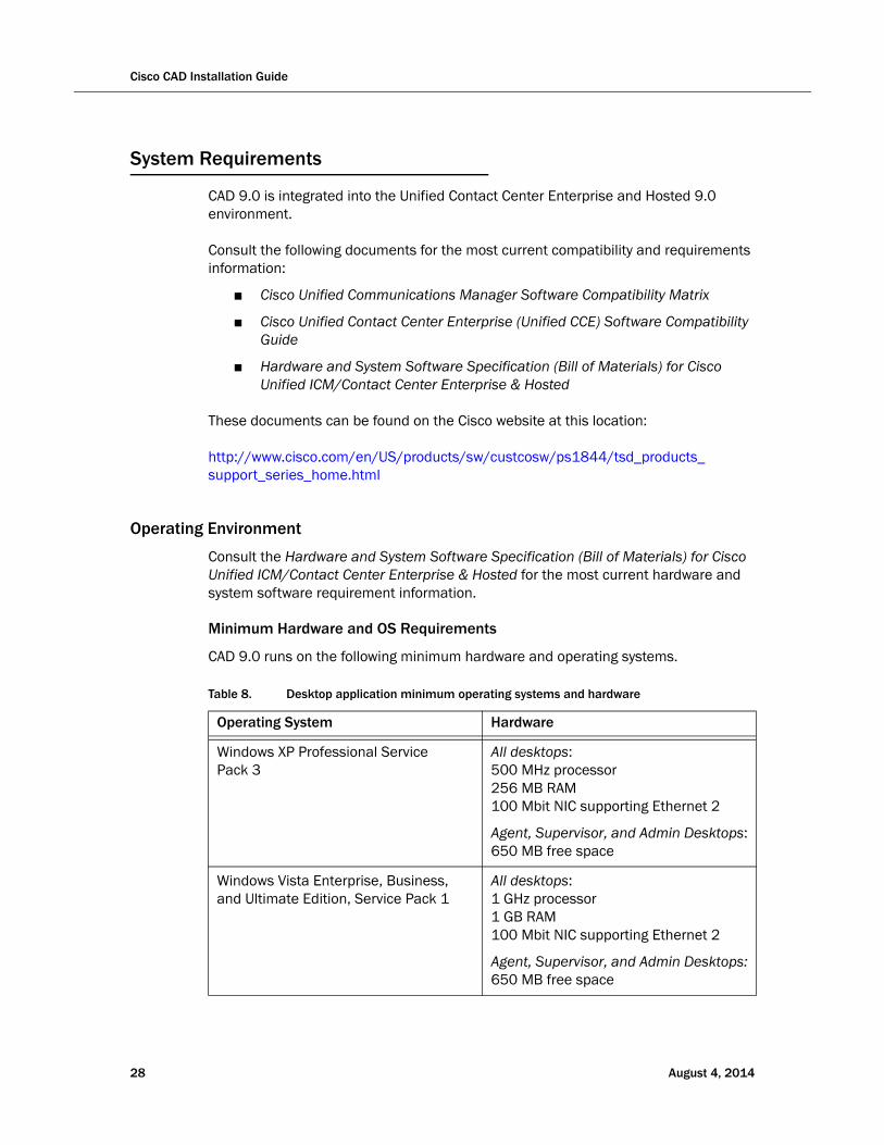
Minimum Hardware and OS Requirements
CAD 9.0 runs on the following minimum hardware and operating systems.
Table 8. Desktop application minimum operating systems and hardware
Operating System Hardware
Windows XP Professional Service Pack 3
All desktops:500 MHz processor256 MB RAM100 Mbit NIC supporting Ethernet 2
Agent, Supervisor, and Admin Desktops:650 MB free space
Windows Vista Enterprise, Business, and Ultimate Edition, Service Pack 1
All desktops:1 GHz processor1 GB RAM100 Mbit NIC supporting Ethernet 2
Agent, Supervisor, and Admin Desktops:650 MB free space
28 August 4, 2014

System Requirements
Operating Environment Language Requirements
The CAD base services must be installed on machines running an English language operating system.
The CAD desktop applications can be installed on machines running an English language or a localized operating system. The following desktop applications are localized:
■ Agent Desktop
■ CAD-BE
■ Supervisor Desktop
■ IP Phone Agent
Desktop Administrator is not localized. However, in non-English contact centers, Desktop Administrator must be run on a machine with a localized operating system so
Windows 7 Enterprise, Professional, and Ultimate Edition Service Pack 132-bit and 64-bit
All desktops:1 GHz processor1 GB RAM (32-bit)2 GB RAM (64-bit)100 Mbit NIC supporting Ethernet 2
Agent, Supervisor, and Admin Desktops:650 MB free space
Red Hat Enterprise Linux v5 CAD-BE only:1 GHz Pentium processor256 MB RAM1 GB free space (for logging)100 Mbit NIC supporting Ethernet 2
Microsoft Terminal Server For minimum hardware requirements, see Integrating CAD with Thin Client and Virtual Desktop EnvironmentsCitrix XenApp
Table 9. Server minimum operating systems and hardware
Operating System Hardware
Windows Server 2008 R2 See the section, “System Software Requirements” in the Hardware and Software Specification (Bill of Materials) for Cisco Unified ICM/Contact Center Enterprise & Hosted
Table 8. Desktop application minimum operating systems and hardware (cont’d)
Operating System Hardware
August 4, 2014 29
Cisco CAD Installation Guide
that chat messages, tooltips, enterprise data names, and other communications within the contact center are in the local language.
A CAD instance (one CAD pair) cannot support more than one localized language. All agents and supervisors must use the same language—there cannot be some agents and supervisors using one language and other agents and supervisors using another language. If you want to use two languages, you must have one CAD pair configured for one language and another CAD pair configured for the second language.
You cannot change languages once CAD is installed. If you want to change languages, you must uninstall CAD base services and install CAD again in a new language.
For a list of supported languages, see Table 6 on page 22.
VPN and NAT Requirements
Virtual private networks (VPNs) provide a more secure connection. Connections over a VPN are supported by the CAD clients (Agent Desktop, Supervisor Desktop, and CAD-BE).
Cisco AnyConnect Secure Mobility Client and Cisco VPN Client have been formally verified to work correctly with CAD clients, and are supported for access. VPN solutions from other vendors might work correctly, but since they have not been formally verified, they are not supported. If you want an alternative VPN solution to be verified, please contact your Cisco distributor.
CAD does not support server-side network address translation (NAT). The CAD clients must be able to connect using the real IP addresses of the server components. When CAD client addresses are translated via NAT, VPN software must be used. If CAD clients are used in a NAT environment without VPN software, a variety of problems might occur, such as agents not being visible in Supervisor Desktop.
Using NAT With IP Phone Agent and CAD-BE
NAT is supported with IP Phone Agent and CAD-BE. However, it is required that you use static IP addresses for the IP Phone Agent and CAD-BE phones as well as Static NAT. Dynamic NAT and address overloading are not supported. Recording and monitoring do not work with IP Phone Agent and CAD-BE when used with NAT.
The NAT IP address is configured in the CAD Configuration Setup utility in the CAD-BE Servers node.
For more information on NAT, see How NAT Works (Cisco document ID 6450), at:
http://www.cisco.com/en/US/tech/tk648/tk361/technologies_tech_note09186a0080094831.shtml
30 August 4, 2014
System Requirements
Third Party Software Requirements
CAD 9.0 requires the following software applications to run successfully.
Microsoft Internet Explorer
Microsoft Internet Explorer must be installed on agent and supervisor PCs to support the integrated browser component of Agent Desktop and Supervisor Desktop. It is also a supported browser for use with CAD-BE. The CAD integrated browser is implemented using the Microsoft WebBrowser control (Shdocvw.dll) that is distributed by Internet Explorer. This library which provides a window in which the user can navigate to websites and files using hyperlinks and URLs. However, it does not represent the full implementation of Internet Explorer. Consequently, differences exist between the behavior of the CAD integrated browser and Internet Explorer. Web pages might render correctly in Internet Explorer but not render correctly, or not render at all, in the CAD integrated browser.
Consult the Hardware and System Software Specification (Bill of Materials) for Cisco Unified ICM/Contact Center Enterprise & Hosted, for information on supported versions of Internet Explorer.
Differences between the CAD integrated browser and Internet Explorer include, but are not limited to, the following:
■ If a third-party web application attempts to launch a new browser window, the CAD integrated browser will open a new tab instead.
■ If a page that contains a JavaScript error is opened from the CAD integrated browser and script error notification is disabled in IE (the default), the CAD integrated browser will not display any information about the error. To see detailed information about the error, you must open the page from IE with script debugged enabled.
■ The CAD integrated browser does not support the more advanced features of Internet Explorer, including the pop-up blocker and the phishing filter.
NOTE: Although the integrated browser has a dependency on the installation of Internet Explorer, the integrated browser is not Internet Explorer. The integrated browser is a simplified web browser and does not include the full Internet Explorer feature set. Web-based applications that require Internet Explorer might not operate successfully in the integrated browser.
NOTE: The integrated browser supports only one web session at a time for web applications that use cookies for session management. For example, you cannot log into a web application that uses cookies in one tab as User A and then log into the same web application in another tab as User B. However, multiple web sessions are supported for web applications that use URL-based session management.
August 4, 2014 31
Cisco CAD Installation Guide
NOTE: For more technical information about the WebBrowser control, refer to the MSDN article CHTMLView Class at:http://msdn2.microsoft.com/en-us/library/42h6dke4(VS.80).aspx
Mozilla Firefox
Mozilla Firefox is a supported browser for use with CAD-BE. Consult the document, Hardware and System Software Specification (Bill of Materials) for Cisco Unified ICM/Contact Center Enterprise & Hosted, for information on supported versions of Firefox. CAD-BE has been tested with Firefox version 12.
Microsoft SQL Server 2008 R2 Standard or Enterprise Edition
Historical data that appears in Cisco Agent Desktop and Cisco Supervisor Desktop can be managed with an onboard SQL Server 2008 R2 (64-bit) instance. For information on choosing a method of data storage, see "Configuring Microsoft SQL Server 2008 R2 for CAD 9.0" on page 41.
OpenLDAP
System configuration data is maintained using OpenLDAP V2.4.16 Directory Services on the CAD server.
CTI OS
Computer Telephony Integration Object Server (CTI OS) must be installed on the CTI server before installing the CAD services. You might want to edit several registry keys to enable Agent Desktop to receive all CTI events. See "Signing Client CTI OS Security Certificates" on page 151 for information on changing these registry keys.
Consult the document, Hardware and System Software Specification (Bill of Materials) for Cisco Unified ICM/Contact Center Enterprise & Hosted, for information on supported versions of CTI OS (see "Operating Environment" on page 28 for the document URL).
Monitoring Requirements
CAD supports both CAD-based (agent-based) monitoring and Unified CM-based (call-based) monitoring. CAD-based monitoring can be implemented either through the desktop or the server.
NOTE: If Unified CM-based monitoring is used, CAD-based recording services are not available.
The type of monitoring that is used is specified when CTI OS is installed. CAD uses either Unified CM-based or CAD-based monitoring, not both. Supervisor Desktop automatically determines which kind of monitoring is used when it is launched.
32 August 4, 2014

System Requirements
NOTE: CAD-based monitoring requires codecs G.711 and G.729.
For more information about monitoring, see the white paper, Configuring and Troubleshooting VoIP Monitoring, available for download at www.cisco.com.
August 4, 2014 33
Cisco CAD Installation Guide
Supported IP Phones
For a list of IP phones that are supported with Agent Desktop, CAD-BE, and IP Phone Agent, see the Cisco Unified Contact Center Enterprise (Unified CCE) Software Compatibility Guide available at:
http://www.cisco.com/en/US/products/sw/custcosw/ps1844/tsd_products_support_series_home.html
NOTE: Unified CCE does not support Internet Protocol version 6 (IPv6) agent phones and requires agents to use IPv4 phones only.
Caveats on Using a Cisco 7920 Wireless Phone
Only SPAN port monitoring can be used with the 7920 wireless IP phone. The port that is to be included in the SPAN is the one to which the access point is wired.
Due to the nature of the 7920 phone’s mobility, there are certain conditions under which monitoring and/or recording calls might result in gaps in the voice:
■ Agent to agent conversations when both agents are using the same wireless access point
■ When an agent roams from one monitoring domain to another
The 7920 phone is not supported as a second line appearance for an agent’s wired phone.
34 August 4, 2014
August 4, 2014
Before You Install CAD 9.0
Overview
Before you install CAD 9.0, you must complete the following tasks.
■ Read the CAD 9.0 release notes, available at:
http://www.cisco.com/en/US/products/sw/custcosw/ps1844/prod_release_notes_list.html
■ Configure Unified ICM.
■ Modify the registry key entries for supervisor monitoring and recording on agents’ non-ACD calls.
■ Prepare user accounts and permissions for CAD to integrate with other Unified CCE components.
■ Configure Microsoft SQL Server 2008 R2 for CAD 9.0.
These tasks are described below.
35

Cisco CAD Installation Guide
Configuring Unified ICM
Supervisors and Teams
For CAD 9.0 applications to work properly, your agents must be organized into teams and some must be designated as supervisors. This is accomplished in Unified ICM. See your Unified ICM documentation for information on how to do this.
Enterprise Data and Call History
In order to correctly display enterprise data and call history in CAD, you must enable the “Permit application routing” option. This option is located on the List Tools > Dialed Number/Script Selector List node in ICM Configuration Manager.
Skills Statistics
The number displayed in the Skills statistic field “Waiting” in Agent Desktop and Supervisor Desktop represents the number of calls currently queued to the skill group. This number is dependent on how you configure skill groups and set up queues in Unified ICM Configuration Manager. The following rules apply:
■ If calls are queued to a base skill group, there must be no sub skill groups configured.
■ If a base skill group does have sub skill groups configured, calls must be queued to the sub skill groups, not the base skill group.
Calls that are queued to a base skill group are reported in the Waiting field.
If sub skill groups are configured, calls are queued to those sub skill groups. Only the calls queued to the primary sub skill group are reported in the Waiting field.
Agents must be assigned to the base skill group in order for the supervisor to view a team’s skill data in Supervisor Desktop. Only the base skill groups appear in the Supervisor Desktop skill statistics.
If sub skill groups are configured, agents must be assigned to those groups because calls are queued to the sub skill group; they cannot be assigned to the base skill group. In that case, no skill data is displayed in Supervisor Desktop.
See your Unified ICM Configuration Manager documentation for more information on setting up skill groups and queues.
36 August 4, 2014

Configuring Unified ICM
Reason Codes
Starting with CAD release 7.1, reason codes are created and maintained in Unified ICM and pulled into CAD. In previous versions of CAD, reason codes could be created and maintained in both Unified ICM and in CAD.
If you are upgrading from a version of CAD older than 7.1, any reason codes you might have created in CAD will be lost in the upgrade. If you want those reason codes to be available in this version of CAD, make sure they are created in Unified ICM.
August 4, 2014 37
Cisco CAD Installation Guide
Configuring Non-ACD Call (Multi-line) Settings
A call is defined as an ACD call if it meets one or more of the following criteria:
■ The call is assigned to an agent from a voice CSQ
■ At least one of the participants of the call is using an ACD line
■ The call is transferred from an ACD line
■ The call is conferenced with an ACD call to any other line
All other calls are considered non-ACD calls by the system and appear in Agent Desktop and CAD-BE if your system is configured to display them.
With multi-line settings enabled, an agent’s phone supports one ACD line and up to three non-ACD lines. You can configure the non-ACD calls settings so that agents and supervisors can perform all general operations with the non-ACD calls (for example, answering, transferring, and conferencing).
You can enable or disable the following functions on inbound non-ACD calls:
■ Agent and supervisor call display and call control actions
■ Supervisor call monitoring and recording
■ Supervisor call barge-in and intercept
Non-ACD call settings should be configured in all the three locations: Unified CCE Configuration Manager PG Explorer, on the CTI OS server, and Desktop Administrator.
Call Display
The non-ACD call display setting is configured in Unified CCE Configuration Manager Peripheral Gateway Explorer. The default setting is to display only ACD calls in Agent Desktop, Supervisor Desktop, and CAD-BE.
If you want to display non-ACD calls in these applications and allow agents and supervisors to perform call control actions on them, you need to change the value of the Agent Phone Line Control parameter in PG Explorer. For information about configuring this parameter, see “Configuring the System Peripheral Gateways” in the Configuration Guide for Cisco Unified ICM/Contact Center Enterprise and Hosted at:
http://www.cisco.com/en/US/products/sw/custcosw/ps1844/products_installation_and_configuration_guides_list.html
38 August 4, 2014

Configuring Non-ACD Call (Multi-line) Settings
Call Monitoring and Recording
Non-ACD call monitoring and recording settings are configured on the CTI OS server. If non-ACD calls are displayed, the ability for supervisors to monitor and record agents’ non-ACD calls is enabled by default.
If you want to disable non-ACD call monitoring and recording, you need to change the value of the StopSMNonACDCall registry subkey on the CTI OS server. Then, after you restart the CTI OS server, you must restart the Sync Service to make the change take effect in CAD. For detailed information about configuring this parameter, see “Installing and Configuring the Silent Monitor Service” in the CTI OS System Manager Guide for Cisco Unified ICM/Contact Center Enterprise & Hosted at:
http://www.cisco.com/en/US/products/sw/custcosw/ps1844/prod_installation_guides_list.html
Call Barge-in and Intercept
If you want to allow supervisors to barge in and intercept agents’ non-ACD calls, you need to check the Non-ACD Calls check box in the Display Settings page in Desktop Administrator. This option is disabled by default.
August 4, 2014 39
Cisco CAD Installation Guide
Preparing User Accounts and Permissions
Before you install CAD base services, you must complete the following tasks:
1. Make the server (both servers in an HA environment) on which you are going to install the CAD base services a member of a domain.
The server on which you install the CAD base services must be a member of a domain, not of a workgroup. If you change the domain after the services are installed, or switch from workgroup to domain, you must reinstall the CAD base services in order to avoid problems with partial or no service when running the CAD desktop applications.
2. Create a user account (on both servers) in Windows Computer Management with the following requirements:
■ The user must have local administrator privileges.
■ The user account must have a password. If either of the servers does not have a password, replication setup will fail because the subscriber cannot connect to the publisher to configure the replication.
■ The same user account must exist on the ICM Admin Workstation computer.
■ The user must have read privileges for the ICM Admin Workstation database.
■ This user account must be used to install SQL Server 2008 R2 and also to install the CAD base services on both Side A and Side B.
3. You must configure the Sync service to connect to the Admin Workstation SQL database via a TCP/IP connection. Run the SQL Server Network Utility on the Admin Workstation machine. On the General tab, ensure that TCP/IP is enabled.
40 August 4, 2014
Configuring Microsoft SQL Server 2008 R2 for CAD 9.0
Configuring Microsoft SQL Server 2008 R2 for CAD 9.0
CAD stores some historical information in Microsoft SQL Server. This information provides the content for two reports available in Agent Desktop and Supervisor Desktop (the Agent State Log and Agent Call Log) and the Supervisor Record Viewer. SQL Server retains agent state information for one day and agent call log and recording information for a rolling seven day period.
You must purchase and install SQL Server 2008 R2 and create a separate SQL Server instance that hosts the CAD base services (on both servers in a replicated system). SQL Server and CAD base services must be installed on the same machine.
NOTE: Prior implementations of CAD 8.0, 8.5, and 9.0 supported the use of flat files or Microsoft SQL Server as the data store. As a matter of policy, effective immediately with release 9.0(3), all customers with new deployments of any version of Cisco Agent Desktop must use SQL Server as the data store, and not flat files. The rationale behind this policy is that deployments with a fully replicated SQL Server database experience a more complete feature set and better performance and stability.
Customers who are upgrading to CAD 9.0(3) from a previous version of CAD that was run on Windows Server 2003 (CAD 7.5, 7.6, 8.0, 8.5(1), and 8.5(2a)) must migrate to SQL Server 2008 R2 as the data store.
Customers who used flat files with CAD 8.5(4) and CAD 9.0(1a) running on Windows Server 2008 R2 can continue to use flat files when upgrading to CAD 9.0(3), but are also encouraged to migrate to SQL Server 2008 R2. CAD documentation outlines the caveats associated with the use of flat files, including loss of functionality during fail over situations that might be cause by several reasons, network issues being the most common. Cisco Support and TAC reserves the right to request a migration to SQL Server 2008 R2 as a resolution plan.
See "System Requirements" on page 28 for information on supported versions of SQL Server.
SQL Server in a High Availability Configuration
In an HA configuration, the Recording and Statistics services write historical data to the SQL Server databases that reside on the active and inactive sides. Also, SQL Server replication services ensure that the data saved on both systems is identical.
August 4, 2014 41
Cisco CAD Installation Guide
Modifying the Database Size Limit
When the CAD base services are installed on the server, the maximum database size for CAD is limited to 2GB. However, you can modify the database size as needed.
To modify the database size limit:
1. Choose Start > All Programs > Microsoft SQL Server 2008 > SQL Server Management Studio Express. The Microsoft SQL Server Management Studio Express window appears.
2. Click New Query and select the CAD SQL named instance from the drop-down list to connect to the CAD SQL named instance.
3. In the query pane, enter the following SQL statements and click Execute. In this sample, the database size is reset to 1000 GB.
use master
alter database fcrassvr
modify FILE (NAME=FCRasSvr_Data,MAXSIZE=1000GB)
4. After executing the SQL statement, close the SQL Server Management Studio Express window.
Installing and Configuring SQL Server 2008 R2
Before proceeding with the SQL Server 2008 R2 installation, you must create the user account detailed in "Preparing User Accounts and Permissions" on page 40. For CAD to function properly, the Recording and Statistics service must connect to both the Admin Workstation database as well as its own local database. If you are using NT (Windows) Authentication to connect to both databases, the same user must be used for authentication. If this user is different than the local user that is currently logged in, you must first create this user with local administrator privileges in Windows Computer Management before you install SQL Server.
You must use this account to install SQL Server 2008 R2 and CAD base services. Later, you must specify this user in step 16 of the procedure below.
If there are any firewalls running (for example, the default Windows Firewall), make sure that the firewall includes an exception for SQL Server. If there is no exception and a firewall is enabled, the Recording & Statistics service will not work.
Also, verify you have an active internet connection.
The following settings must be configured during the SQL Server 2008 R2 installation for CAD to function properly. Navigate between nodes using the Next and Back buttons.
42 August 4, 2014
Configuring Microsoft SQL Server 2008 R2 for CAD 9.0
NOTE: As a best practice, use NT (Windows) authentication as per the procedure below. If you want to use SQL authentication, some steps must be modified. Consult your SQL Server documentation for more information.
To install and configure a Microsoft SQL Server 2008 R2 named instance for CAD 9.0:
1. Start the SQL Server 2008 R2 installer (setup.exe).
2. On the SQL Server Installation Center window, select Installation in the left navigation pane.
3. Select New installation or add features to an existing installation. The SQL Server 2008 R2 Setup window appears.
4. Accept the prompts and allow the support files to install.
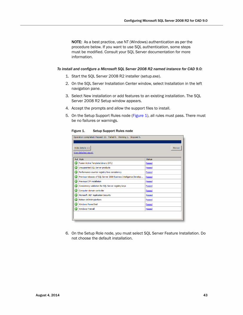
5. On the Setup Support Rules node (Figure 1), all rules must pass. There must be no failures or warnings.
Figure 1. Setup Support Rules node
6. On the Setup Role node, you must select SQL Server Feature Installation. Do not choose the default installation.
August 4, 2014 43
Cisco CAD Installation Guide
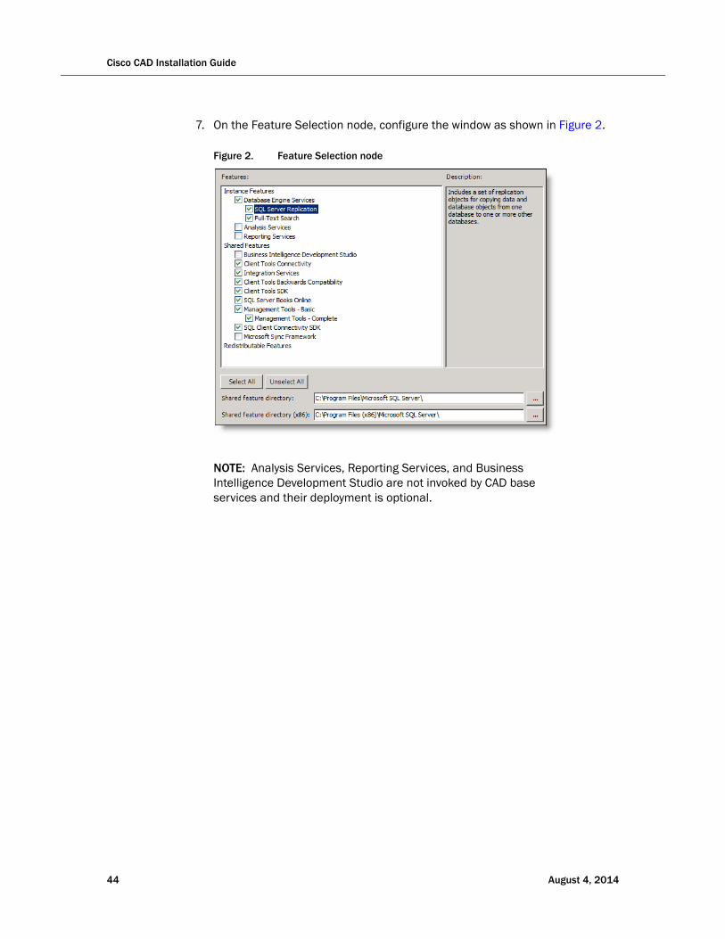
7. On the Feature Selection node, configure the window as shown in Figure 2.
Figure 2. Feature Selection node
NOTE: Analysis Services, Reporting Services, and Business Intelligence Development Studio are not invoked by CAD base services and their deployment is optional.
44 August 4, 2014
Configuring Microsoft SQL Server 2008 R2 for CAD 9.0
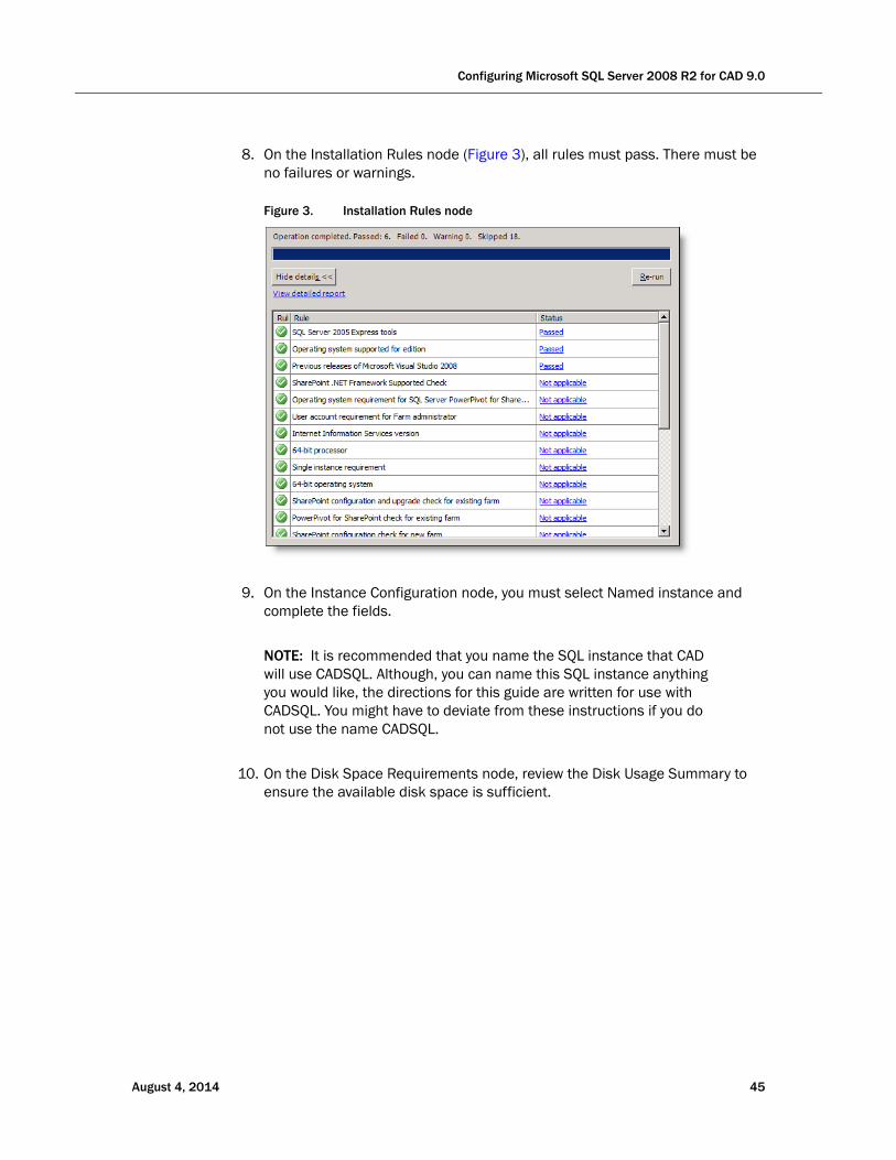
8. On the Installation Rules node (Figure 3), all rules must pass. There must be no failures or warnings.
Figure 3. Installation Rules node
9. On the Instance Configuration node, you must select Named instance and complete the fields.
NOTE: It is recommended that you name the SQL instance that CAD will use CADSQL. Although, you can name this SQL instance anything you would like, the directions for this guide are written for use with CADSQL. You might have to deviate from these instructions if you do not use the name CADSQL.
10. On the Disk Space Requirements node, review the Disk Usage Summary to ensure the available disk space is sufficient.
August 4, 2014 45
Cisco CAD Installation Guide
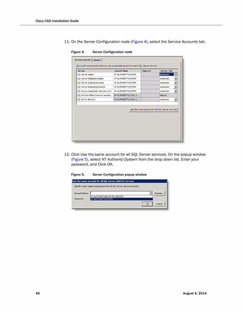
11. On the Server Configuration node (Figure 4), select the Service Accounts tab.
Figure 4. Server Configuration node
12. Click Use the same account for all SQL Server services. On the popup window (Figure 5), select NT Authority\System from the drop down list. Enter your password, and Click OK.
Figure 5. Server Configuration popup window
46 August 4, 2014
Configuring Microsoft SQL Server 2008 R2 for CAD 9.0
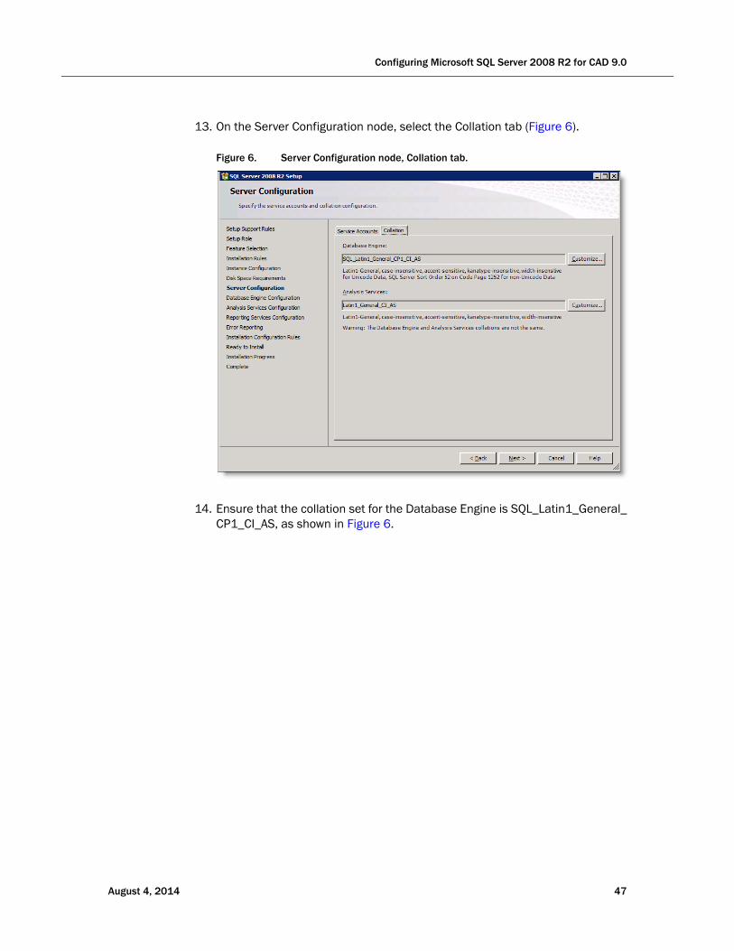
13. On the Server Configuration node, select the Collation tab (Figure 6).
Figure 6. Server Configuration node, Collation tab.
14. Ensure that the collation set for the Database Engine is SQL_Latin1_General_CP1_CI_AS, as shown in Figure 6.
August 4, 2014 47
Cisco CAD Installation Guide
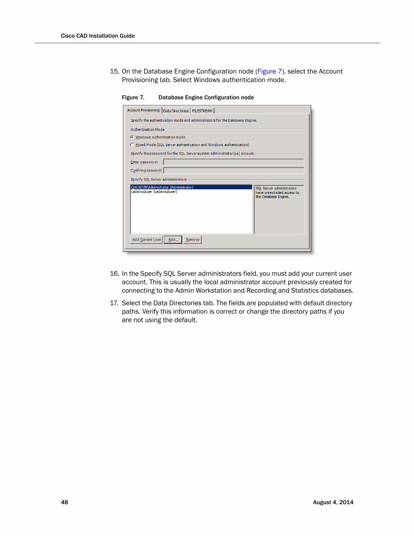
15. On the Database Engine Configuration node (Figure 7), select the Account Provisioning tab. Select Windows authentication mode.
Figure 7. Database Engine Configuration node
16. In the Specify SQL Server administrators field, you must add your current user account. This is usually the local administrator account previously created for connecting to the Admin Workstation and Recording and Statistics databases.
17. Select the Data Directories tab. The fields are populated with default directory paths. Verify this information is correct or change the directory paths if you are not using the default.
48 August 4, 2014
Configuring Microsoft SQL Server 2008 R2 for CAD 9.0
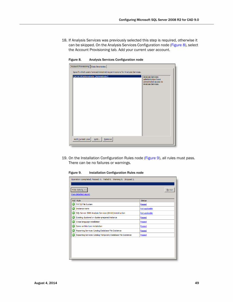
18. If Analysis Services was previously selected this step is required, otherwise it can be skipped. On the Analysis Services Configuration node (Figure 8), select the Account Provisioning tab. Add your current user account.
Figure 8. Analysis Services Configuration node
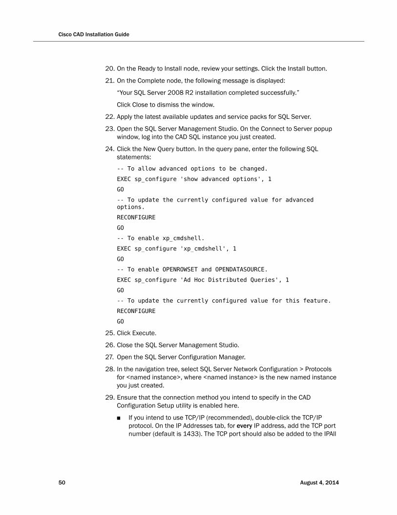
19. On the Installation Configuration Rules node (Figure 9), all rules must pass. There can be no failures or warnings.
Figure 9. Installation Configuration Rules node
August 4, 2014 49
Cisco CAD Installation Guide
20. On the Ready to Install node, review your settings. Click the Install button.
21. On the Complete node, the following message is displayed:
“Your SQL Server 2008 R2 installation completed successfully.”
Click Close to dismiss the window.
22. Apply the latest available updates and service packs for SQL Server.
23. Open the SQL Server Management Studio. On the Connect to Server popup window, log into the CAD SQL instance you just created.
24. Click the New Query button. In the query pane, enter the following SQL statements:
-- To allow advanced options to be changed.
EXEC sp_configure 'show advanced options', 1
GO
-- To update the currently configured value for advanced options.
RECONFIGURE
GO
-- To enable xp_cmdshell.
EXEC sp_configure 'xp_cmdshell', 1
GO
-- To enable OPENROWSET and OPENDATASOURCE.
EXEC sp_configure 'Ad Hoc Distributed Queries', 1
GO
-- To update the currently configured value for this feature.
RECONFIGURE
GO
25. Click Execute.
26. Close the SQL Server Management Studio.
27. Open the SQL Server Configuration Manager.
28. In the navigation tree, select SQL Server Network Configuration > Protocols for <named instance>, where <named instance> is the new named instance you just created.
29. Ensure that the connection method you intend to specify in the CAD Configuration Setup utility is enabled here.
■ If you intend to use TCP/IP (recommended), double-click the TCP/IP protocol. On the IP Addresses tab, for every IP address, add the TCP port number (default is 1433). The TCP port should also be added to the IPAll
50 August 4, 2014
Configuring Microsoft SQL Server 2008 R2 for CAD 9.0
section, if present. Take note of the port number. You will enter it in the CAD Configuration Setup utility (the IP addresses are autofilled from system information). Click Apply and then click OK.
NOTE: CAD cannot use the same port that another SQL instance is using. If another SQL instance is using the port that is entered on the Recording and Statistics Database Configuration node of the CAD Configuration Setup utility, the value in the CAD Configuration Setup utility must be changed to use a different port.
NOTE: After you specify the named pipe or port, you must restart the SQL Server and SQL Server Agent services that correspond to the CAD SQL named instance and the Generic SQL Server Browser service. You can do this by selecting SQL Server Services in the navigation tree, right-clicking on these services, and then selecting Restart.
30. Click Apply, and then click OK. Close the SQL Server Configuration Manager.
If you are using a replicated system, you must complete these steps on both servers.
You are responsible for maintaining the security of your database. No lockdown scripts are run by CAD installers. However, before performing any hardening of your SQL instance, complete the CAD installation in full, including replication setup steps if you plan on using a replicated environment. You must also ensure the Recording and Statistics service is functioning properly with SQL Server 2008 R2.
After the CAD installation is completed in full and you have verified that the Recording and Statistics Database is functioning normally (including replication, if applicable), you can turn off the xp_cmdshell and Ad Hoc Distributed Queries options that you enabled earlier. To do this, repeat steps 23 through 25 above, using the following SQL statements:
-- To disable xp_cmdshell.
EXEC sp_configure 'xp_cmdshell', 0
GO
-- To disable OPENROWSET and OPENDATASOURCE.
EXEC sp_configure 'Ad Hoc Distributed Queries', 0
GO
-- To update the currently configured value for this feature.
RECONFIGURE
GO
-- To prevent advanced options to be changed.
August 4, 2014 51
Cisco CAD Installation Guide
EXEC sp_configure ‘show advanced options’, 0
GO
-- To update the currently configured value for advanced options.
RECONFIGURE
GO
NOTE: If you turn off the xp_cmdshell and Ad Hoc Distributed Queries options after the installation of CAD and later run into issues which require you to administer the Recording and Statistics Database connection through the CAD Configuration Setup Utility, you must again complete steps 23 through 25 from the installation process above to turn these options back on.
For more information on best practices for database security, refer to the following resources:
■ http://msdn.microsoft.com/en-us/library/bb283235%28v=sql.105%29.aspx
■ http://msdn.microsoft.com/en-us/library/ff648664.aspx
Upgrading from SQL Server 2005
If you are upgrading from SQL Server 2005 to SQL Server 2008 R2 on the same system, you can do an over-the-top upgrade.
To upgrade to SQL Server 2008 R2:
1. Start the SQL Server 2008 R2 installer (setup.exe).
2. On the SQL Server Installation Center window, select Installation in the left navigation pane.
3. Select Upgrade from SQL Server 2000, SQL Server 2005 or SQL Server 2008 to SQL Server 2008 R2. The SQL Server 2008 R2 Setup window appears.
4. Accept the prompts and allow the support files to install.
5. Select the SQL Server instance that CAD is using.
6. Accept the prompts. Close the window.
There is no further configuration or replication setup required.
52 August 4, 2014

Configuring Microsoft SQL Server 2008 R2 for CAD 9.0
Upgrading from CAD 7.6
In CAD 7.6 or earlier, the CAD database instance was required to be named CADSQL and was in MSDE (Microsoft SQL Server Desktop Engine) format. In CAD 8.0 and higher, MSDE is no longer used and the database instance can be named anything you wish.
NOTE: You must use a named instance. You cannot use the default instance.
It is recommended that you back up the data in the CADSQL MSDE instance and restore it to the new SQL Server instance (see the Cisco CAD Installation Guide for your old version of CAD for information on backup procedures). If you choose to continue using CADSQL as the instance name, after you have backed up the MSDE instance, you must remove it and create a new instance with that name during SQL Server 2008 R2 installation. This must be done in order to avoid conflicts in CAD with the instance names.
Upgrading from CAD 8.0 or 8.5
CAD 8.0 and CAD 8.5 supported SQL Server 2005. In order for CAD 9.0 to function properly, you must upgrade to SQL Server 2008 R2. See "Upgrading from SQL Server 2005" on page 52 for more information.
August 4, 2014 53

Cisco CAD Installation Guide
54 August 4, 2014
August 4, 2014
Installing CAD 9.0
Overview
If you are installing CAD 9.0 as a first time implementation then you must use Microsoft SQL Server 2008 R2 for your data store.
The installation steps are as follows:
1. Complete the preinstallation preparation. Refer to "Preparing User Accounts and Permissions" on page 40 for more information.
2. Install and configure SQL Server 2008 R2 (on Side A and Side B in a redundant system). See "Configuring Microsoft SQL Server 2008 R2 for CAD 9.0" on page 41 for detailed steps.
3. Install CAD base services on the primary server (Side A) where SQL Server 2008 R2 is installed. Refer to "Installing CAD Base Services" on page 56 for detailed steps.
4. Configure CAD base services on Side A with the CAD Configuration Setup utility. Refer to "Configuring a Primary Server in a Replicated System" on page 62 for steps to configure CAD services on the primary server (Side A). For more information about the CAD Configuration Setup utility refer to "CAD Configuration Setup Utility" on page 60.
The nodes will appear in the following order:
a. Unified CM SOAP AXL Access (page 64)
b. Unified Communications Manager (page 66)
c. CTI Server (Unified CM) (page 68)
d. CTI OS (page 70)
e. ICM Admin Workstation Distributor (page 71)
f. ICM Admin Workstation Database (page 73)
g. Recording and Statistics Database Configuration (page 75)
h. Recording and Statistics Service Database (page 78)
55
Cisco CAD Installation Guide
i. Restore Backup Data (page 80)
5. License CAD with Unified CCE License Administration. Refer to "Licensing CAD 9.0" on page 94 for more information.
6. Install CAD services on the secondary server (Side B). The steps are the same as they were on Side A. Refer to "Installing CAD Base Services" on page 56 for more information.
7. Configure CAD base services on Side B with the CAD Configuration Setup utility. Refer to "Configuring a Secondary Server in a Replicated System" on page 91 for more information. The fields will already be completed based on the information you entered while configuring CAD on Side A. Verify this information is correct.
NOTE: You do not have to complete Unified CCE License Administration on Side B.
8. Modify the Peripheral Gateway Registry. Refer to "Modifying the Peripheral Gateway Registry" on page 97 for detailed steps.
9. Configure Client MSI Files. Refer to "Configuring CAD Client MSI Files" on page 99 for more information.
10. Install Desktop Administrator on the administrator desktop(s). Refer to "Installing Desktop Applications" on page 106 for more information.
11. Install the other client desktops.
a. Install Agent Desktop on the agent desktops.
b. Install Supervisor Desktop on the supervisor desktops.
c. Configure the Java Runtime Error (JRE) browser plug-in on the CAD-BE agent desktops.
Installing CAD Base Services
The CAD base services are installed using the InstallSheild Wizard.
To run the InstallShield Wizard:
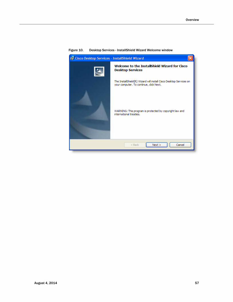
1. Launch the setup.exe file from the product CD to start the installation process (Figure 10).
56 August 4, 2014
Overview
Figure 10. Desktop Services - InstallShield Wizard Welcome window
August 4, 2014 57
Cisco CAD Installation Guide
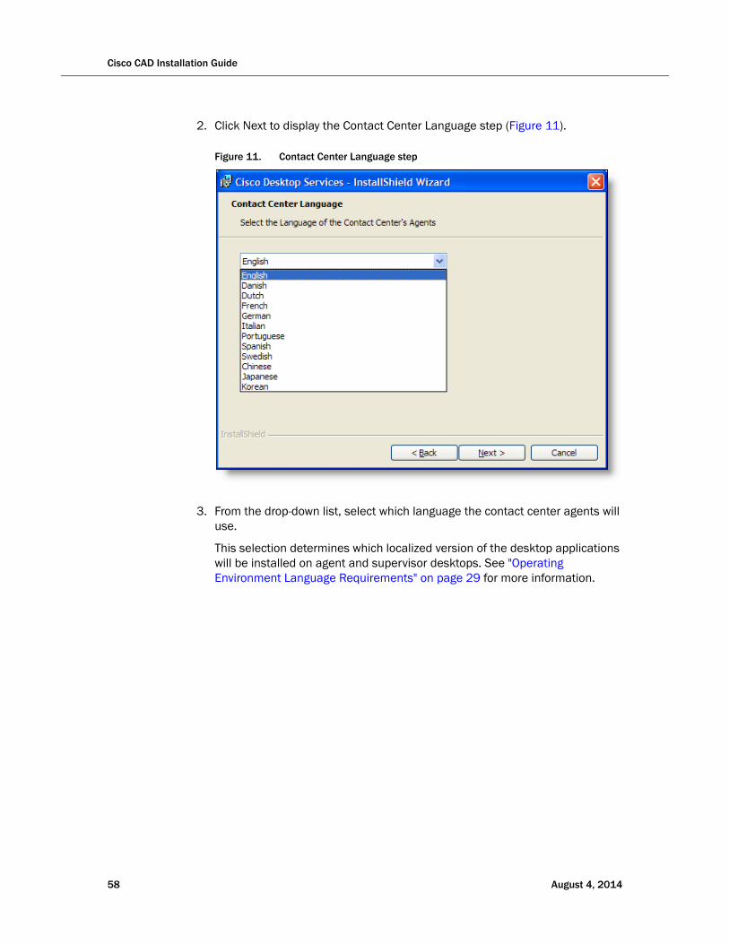
2. Click Next to display the Contact Center Language step (Figure 11).
Figure 11. Contact Center Language step
3. From the drop-down list, select which language the contact center agents will use.
This selection determines which localized version of the desktop applications will be installed on agent and supervisor desktops. See "Operating Environment Language Requirements" on page 29 for more information.
58 August 4, 2014
Overview
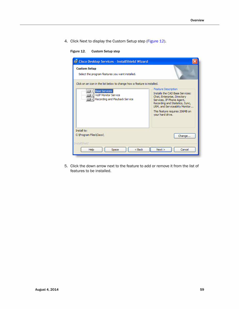
4. Click Next to display the Custom Setup step (Figure 12).
Figure 12. Custom Setup step
5. Click the down arrow next to the feature to add or remove it from the list of features to be installed.
August 4, 2014 59
Cisco CAD Installation Guide
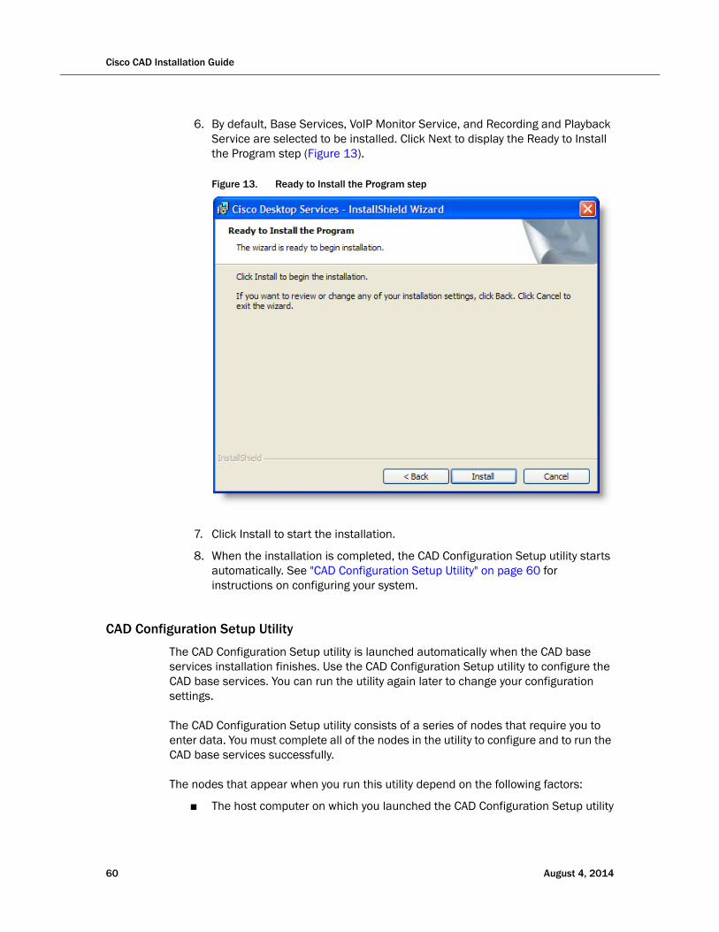
6. By default, Base Services, VoIP Monitor Service, and Recording and Playback Service are selected to be installed. Click Next to display the Ready to Install the Program step (Figure 13).
Figure 13. Ready to Install the Program step
7. Click Install to start the installation.
8. When the installation is completed, the CAD Configuration Setup utility starts automatically. See "CAD Configuration Setup Utility" on page 60 for instructions on configuring your system.
CAD Configuration Setup Utility
The CAD Configuration Setup utility is launched automatically when the CAD base services installation finishes. Use the CAD Configuration Setup utility to configure the CAD base services. You can run the utility again later to change your configuration settings.
The CAD Configuration Setup utility consists of a series of nodes that require you to enter data. You must complete all of the nodes in the utility to configure and to run the CAD base services successfully.
The nodes that appear when you run this utility depend on the following factors:
■ The host computer on which you launched the CAD Configuration Setup utility
60 August 4, 2014
Overview
■ If you are running the CAD Configuration Setup utility for the first time or if you are running it again to change your configuration settings
■ The services and applications that are running on the computer on which you launched the CAD Configuration Setup utility
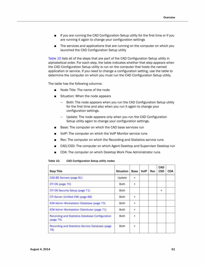
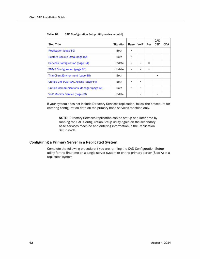
Table 10 lists all of the steps that are part of the CAD Configuration Setup utility in alphabetical order. For each step, the table indicates whether that step appears when the CAD Configuration Setup utility is run on the computer that hosts the named application or service. If you need to change a configuration setting, use the table to determine the computer on which you must run the CAD Configuration Setup utility.
The table has the following columns:
■ Node Title: The name of the node
■ Situation: When the node appears
— Both: The node appears when you run the CAD Configuration Setup utility for the first time and also when you run it again to change your configuration settings.
— Update: The node appears only when you run the CAD Configuration Setup utility again to change your configuration settings.
■ Base: The computer on which the CAD base services run
■ VoIP: The computer on which the VoIP Monitor service runs
■ Rec: The computer on which the Recording and Statistics service runs
■ CAD/CSD: The computer on which Agent Desktop and Supervisor Desktop run
■ CDA: The computer on which Desktop Work Flow Administrator runs
Table 10. CAD Configuration Setup utility nodes
Step Title Situation Base VoIP RecCADCSD CDA
CAD-BE Servers (page 81) Update ×
CTI OS (page 70) Both ×
CTI OS Security Setup (page 71) Both ×
CTI Server (Unified CM) (page 68) Both ×
ICM Admin Workstation Database (page 73) Both ×
ICM Admin Workstation Distributor (page 71) Both ×
Recording and Statistics Database Configuration (page 75)
Both ×
Recording and Statistics Service Database (page 78)
Both ×
August 4, 2014 61
Cisco CAD Installation Guide
If your system does not include Directory Services replication, follow the procedure for entering configuration data on the primary base services machine only.
NOTE: Directory Services replication can be set up at a later time by running the CAD Configuration Setup utility again on the secondary base services machine and entering information in the Replication Setup node.
Configuring a Primary Server in a Replicated System
Complete the following procedure if you are running the CAD Configuration Setup utility for the first time on a single server system or on the primary server (Side A) in a replicated system.
Replication (page 89) Both ×
Restore Backup Data (page 80) Both ×
Services Configuration (page 84) Update × × ×
SNMP Configuration (page 86) Update × × ×
Thin Client Environment (page 88) Both ×
Unified CM SOAP AXL Access (page 64) Both × ×
Unified Communications Manager (page 66) Both × ×
VoIP Monitor Service (page 83) Update × ×
Table 10. CAD Configuration Setup utility nodes (cont’d)
Step Title Situation Base VoIP RecCADCSD CDA
62 August 4, 2014
Overview
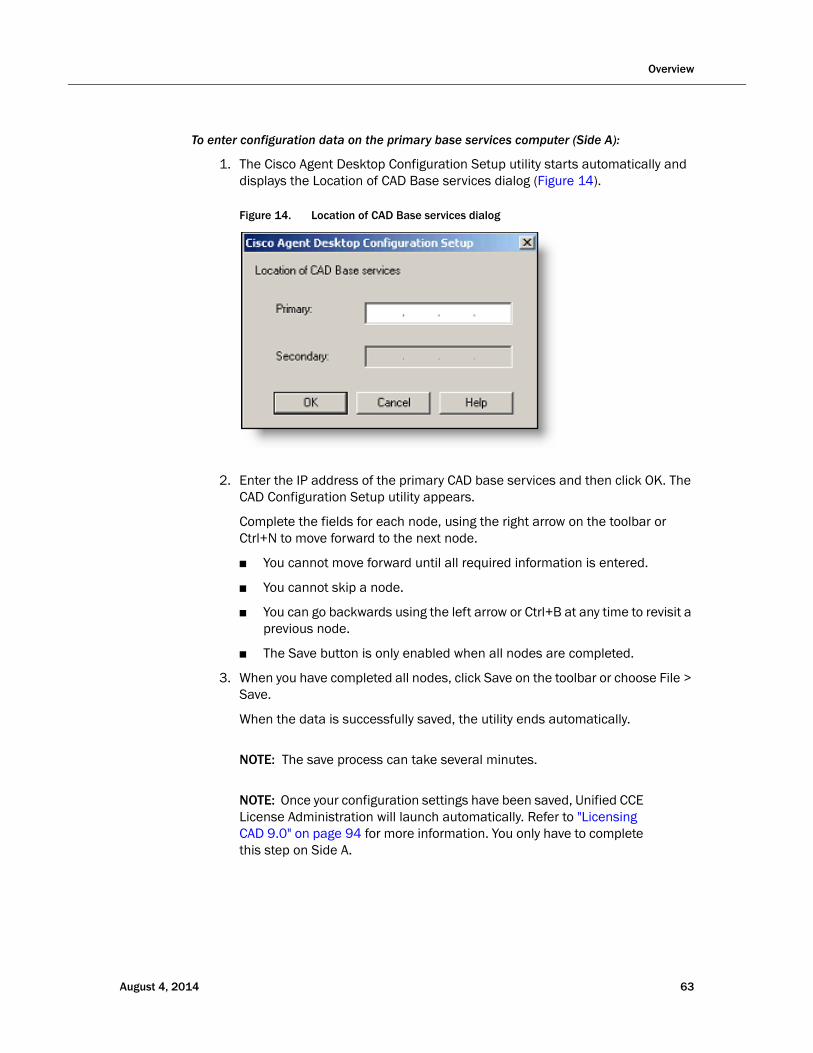
To enter configuration data on the primary base services computer (Side A):
1. The Cisco Agent Desktop Configuration Setup utility starts automatically and displays the Location of CAD Base services dialog (Figure 14).
Figure 14. Location of CAD Base services dialog
2. Enter the IP address of the primary CAD base services and then click OK. The CAD Configuration Setup utility appears.
Complete the fields for each node, using the right arrow on the toolbar or Ctrl+N to move forward to the next node.
■ You cannot move forward until all required information is entered.
■ You cannot skip a node.
■ You can go backwards using the left arrow or Ctrl+B at any time to revisit a previous node.
■ The Save button is only enabled when all nodes are completed.
3. When you have completed all nodes, click Save on the toolbar or choose File > Save.
When the data is successfully saved, the utility ends automatically.
NOTE: The save process can take several minutes.
NOTE: Once your configuration settings have been saved, Unified CCE License Administration will launch automatically. Refer to "Licensing CAD 9.0" on page 94 for more information. You only have to complete this step on Side A.
August 4, 2014 63
Cisco CAD Installation Guide
CAD Configuration Setup Utility Nodes
This section describes the CAD Configuration Setup utility nodes.
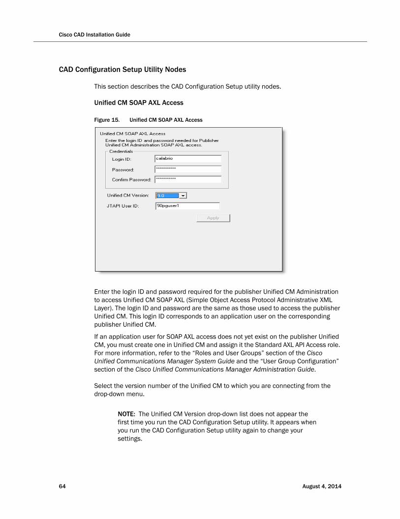
Unified CM SOAP AXL Access
Figure 15. Unified CM SOAP AXL Access
Enter the login ID and password required for the publisher Unified CM Administration to access Unified CM SOAP AXL (Simple Object Access Protocol Administrative XML Layer). The login ID and password are the same as those used to access the publisher Unified CM. This login ID corresponds to an application user on the corresponding publisher Unified CM.
If an application user for SOAP AXL access does not yet exist on the publisher Unified CM, you must create one in Unified CM and assign it the Standard AXL API Access role. For more information, refer to the “Roles and User Groups” section of the Cisco Unified Communications Manager System Guide and the “User Group Configuration” section of the Cisco Unified Communications Manager Administration Guide.
Select the version number of the Unified CM to which you are connecting from the drop-down menu.
NOTE: The Unified CM Version drop-down list does not appear the first time you run the CAD Configuration Setup utility. It appears when you run the CAD Configuration Setup utility again to change your settings.
64 August 4, 2014

Enter the required JTAPI User ID, which is case sensitive.
For more information about user roles in Unified CM, refer to the “Roles and User Groups” section of the Cisco Unified Communications Manager System Guide. For more information on the JTAPI user for Unified CM, refer to the “How to Configure Users for the Phones, the Unified CM PG, and Unified IP IVR” section of the Installation and Configuration Guide Cisco Unified Contact Center Enterprise. These documents are available on the Cisco website (www.cisco.com).
NOTE: If you change these settings after initial setup, you must restart the Sync service and the VoIP Monitor service to ensure that the change is registered with them properly.
August 4, 2014 65
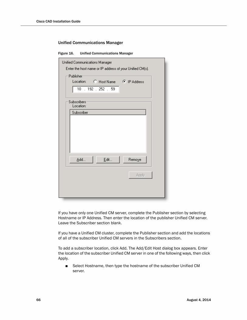
Cisco CAD Installation Guide
Unified Communications Manager
Figure 16. Unified Communications Manager
If you have only one Unified CM server, complete the Publisher section by selecting Hostname or IP Address. Then enter the location of the publisher Unified CM server. Leave the Subscriber section blank.
If you have a Unified CM cluster, complete the Publisher section and add the locations of all of the subscriber Unified CM servers in the Subscribers section.
To add a subscriber location, click Add. The Add/Edit Host dialog box appears. Enter the location of the subscriber Unified CM server in one of the following ways, then click Apply.
■ Select Hostname, then type the hostname of the subscriber Unified CM server.
66 August 4, 2014

■ Select Hostname, then choose the hostname of the subscriber Unified CM server from the drop-down list.
■ Select IP Address, then type the IP address of the subscriber Unified CM server.
NOTE: If you change these settings after initial setup, you must restart the Sync service and the VoIP Monitor service to ensure that any changes are registered with them properly.
August 4, 2014 67
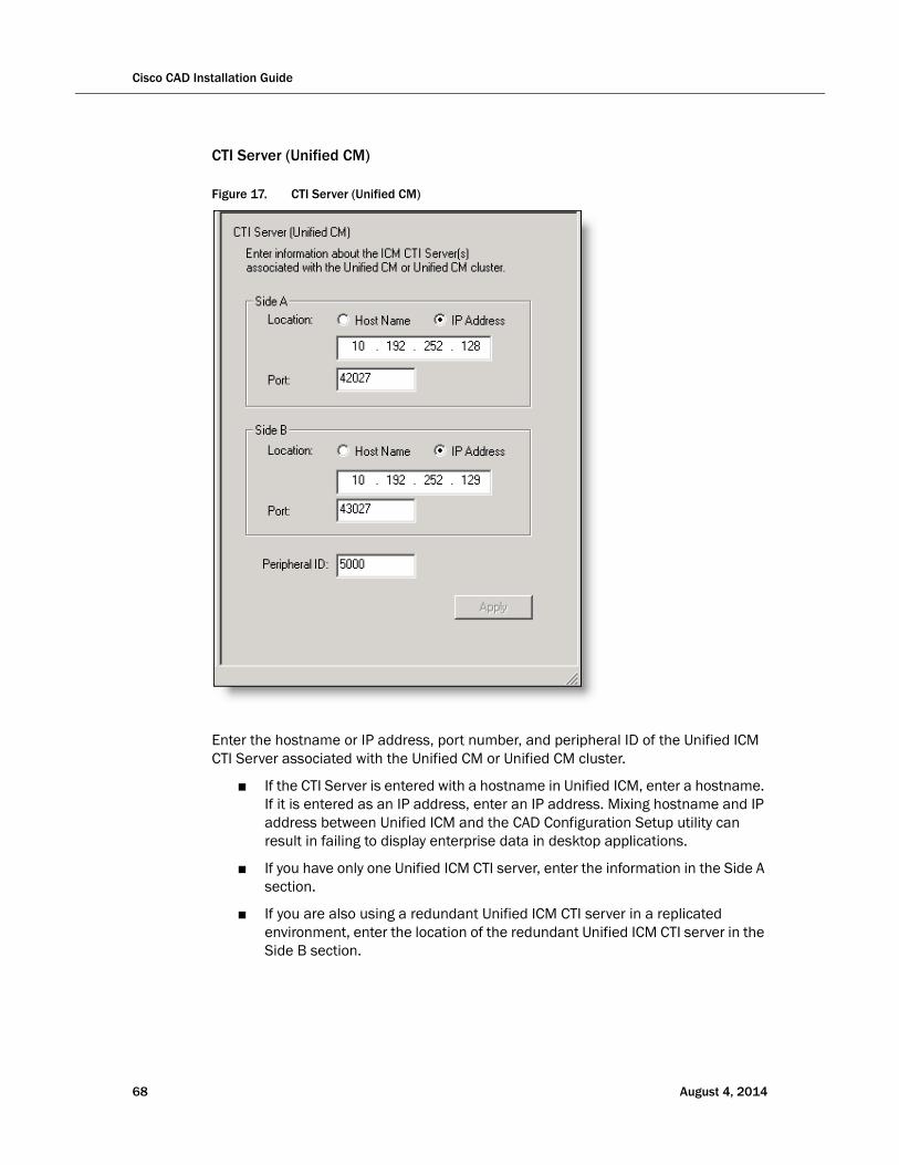
Cisco CAD Installation Guide
CTI Server (Unified CM)
Figure 17. CTI Server (Unified CM)
Enter the hostname or IP address, port number, and peripheral ID of the Unified ICM CTI Server associated with the Unified CM or Unified CM cluster.
■ If the CTI Server is entered with a hostname in Unified ICM, enter a hostname. If it is entered as an IP address, enter an IP address. Mixing hostname and IP address between Unified ICM and the CAD Configuration Setup utility can result in failing to display enterprise data in desktop applications.
■ If you have only one Unified ICM CTI server, enter the information in the Side A section.
■ If you are also using a redundant Unified ICM CTI server in a replicated environment, enter the location of the redundant Unified ICM CTI server in the Side B section.
68 August 4, 2014

■ Enter the correct peripheral ID for your system. The default value is 5000. The peripheral ID is used by services to filter information such as agents and skills. You can find the peripheral ID for your system by using PG Explorer in the Unified ICM Configuration Manager.
NOTE: If you change the peripheral ID, you must restart the Sync service, the Enterprise service, and the BIPPA service to ensure that the change is registered with them properly.
August 4, 2014 69
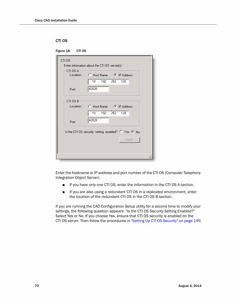
Cisco CAD Installation Guide
70 August 4, 2014
CTI OS
Figure 18. CTI OS
Enter the hostname or IP address and port number of the CTI OS (Computer Telephony Integration Object Server).
■ If you have only one CTI OS, enter the information in the CTI OS A section.
■ If you are also using a redundant CTI OS in a replicated environment, enter the location of the redundant CTI OS in the CTI OS B section.
If you are running the CAD Configuration Setup utility for a second time to modify your settings, the following question appears: “Is the CTI OS Security Setting Enabled?” Select Yes or No. If you choose Yes, ensure that CTI OS security is enabled on the CTI OS server. Then follow the procedures in "Setting Up CTI OS Security" on page 149.
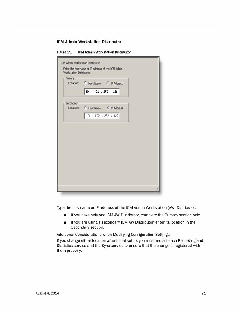
ICM Admin Workstation Distributor
Figure 19. ICM Admin Workstation Distributor
Type the hostname or IP address of the ICM Admin Workstation (AW) Distributor.
■ If you have only one ICM AW Distributor, complete the Primary section only.
■ If you are using a secondary ICM AW Distributor, enter its location in the Secondary section.
Additional Considerations when Modifying Configuration Settings
If you change either location after initial setup, you must restart each Recording and Statistics service and the Sync service to ensure that the change is registered with them properly.
August 4, 2014 71
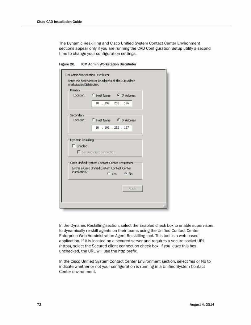
Cisco CAD Installation Guide
The Dynamic Reskilling and Cisco Unified System Contact Center Environment sections appear only if you are running the CAD Configuration Setup utility a second time to change your configuration settings.
Figure 20. ICM Admin Workstation Distributor
In the Dynamic Reskilling section, select the Enabled check box to enable supervisors to dynamically re-skill agents on their teams using the Unified Contact Center Enterprise Web Administration Agent Re-skilling tool. This tool is a web-based application. If it is located on a secured server and requires a secure socket URL (https), select the Secured client connection check box. If you leave this box unchecked, the URL will use the http prefix.
In the Cisco Unified System Contact Center Environment section, select Yes or No to indicate whether or not your configuration is running in a Unified System Contact Center environment.
72 August 4, 2014
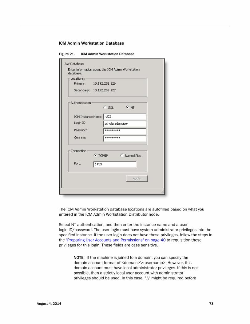
ICM Admin Workstation Database
Figure 21. ICM Admin Workstation Database
The ICM Admin Workstation database locations are autofilled based on what you entered in the ICM Admin Workstation Distributor node.
Select NT authentication, and then enter the instance name and a user login ID/password. The user login must have system administrator privileges into the specified instance. If the user login does not have these privileges, follow the steps in the "Preparing User Accounts and Permissions" on page 40 to requisition these privileges for this login. These fields are case sensitive.
NOTE: If the machine is joined to a domain, you can specify the domain account format of <domain>\<username>. However, this domain account must have local administrator privileges. If this is not possible, then a strictly local user account with administrator privileges should be used. In this case, ".\" might be required before
August 4, 2014 73
Cisco CAD Installation Guide
the username to indicate that the local account, and not the domain account, should be used.
NOTE: It is strongly recommended that you select NT authentication. SQL authentication appears for troubleshooting purposes only.
This is the user account you created during your preinstallation preparation. See "Preparing User Accounts and Permissions" on page 40 for more information.
■ The user must have read privileges for the ICM Admin Workstation database.
■ The user must have read and write privileges and an account on the ICM Admin Workstation computer.
Select the connection type, TCP/IP or Named Pipes.
■ If TCP/IP (recommended), enter the port number used to connect to the database.
■ If Named Pipes, the field is greyed out. The pipe name is automatically generated based on the above fields.
Additional Considerations for Modifying Configuration Settings
If you are using NT Authentication and change the ICM Login ID or Password on one side, the change will replicate to the other side. However, you must also run the CAD Configuration Setup utility on the other side and click Apply to save this setting to ensure that the Windows Services user is updated properly also.
If you change the connection type settings after initial configuration, you must restart each Recording and Statistics service and the Sync service to ensure that the change is registered with them properly.
74 August 4, 2014
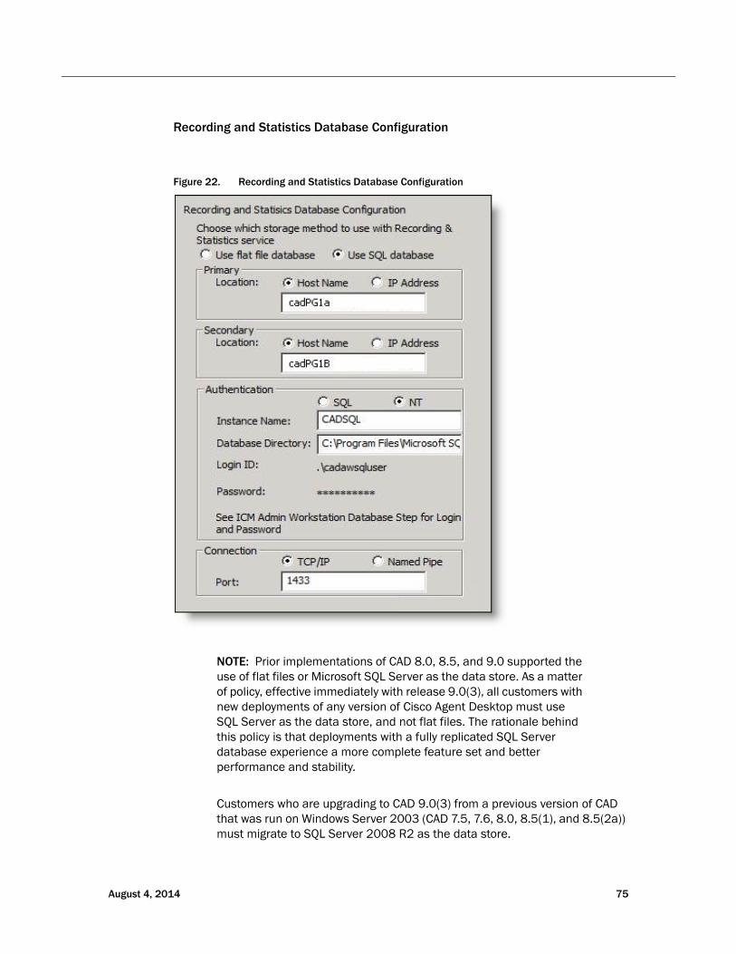
Recording and Statistics Database Configuration
Figure 22. Recording and Statistics Database Configuration
NOTE: Prior implementations of CAD 8.0, 8.5, and 9.0 supported the use of flat files or Microsoft SQL Server as the data store. As a matter of policy, effective immediately with release 9.0(3), all customers with new deployments of any version of Cisco Agent Desktop must use SQL Server as the data store, and not flat files. The rationale behind this policy is that deployments with a fully replicated SQL Server database experience a more complete feature set and better performance and stability.
Customers who are upgrading to CAD 9.0(3) from a previous version of CAD that was run on Windows Server 2003 (CAD 7.5, 7.6, 8.0, 8.5(1), and 8.5(2a)) must migrate to SQL Server 2008 R2 as the data store.
August 4, 2014 75
Cisco CAD Installation Guide
Customers who used flat files with CAD 8.5(4) and CAD 9.0(1a) running on Windows Server 2008 R2 can continue to use flat files when upgrading to CAD 9.0(3), but are also encouraged to migrate to SQL Server 2008 R2. CAD documentation outlines the caveats associated with the use of flat files, including loss of functionality during fail over situations that might be cause by several reasons, network issues being the most common. Cisco Support and TAC reserves the right to request a migration to SQL Server 2008 R2 as a resolution plan.
If you are installing CAD 9.0(3) as a new deployment or if you are upgrading to CAD 9.0(3) from a version of CAD prior to 9.0, you must install CAD 9.0(1a) first and then install 9.0(3).
Unless the deployment meets one of the exceptions above, select Use SQL Server database.
Flat Files
Flat files are selected by default and the rest of the window is disabled. Continue to the next node.
SQL Server
Select Use SQL Server database, and enter the hostnames of the servers that host the primary and secondary Recording & Statistics service.
NOTE: Use the Host Name fields to connect to the database. The IP Address fields are provided for troubleshooting purposes only.
NOTE: You must have SQL Server 2008 R2 (64-bit) installed and configured on both servers (see "Configuring Microsoft SQL Server 2008 R2 for CAD 9.0" on page 41).
Select NT authentication, then complete the following fields:
NOTE: It is strongly recommended that you select NT authentication. SQL authentication appears for troubleshooting purposes only.
■ Instance Name: Enter the CAD SQL instance name.
■ Database Directory: Verify the directory path to the CAD SQL instance database.
All SQL instances are installed to a default location. CAD assumes the SQL instance it is using is installed to this default location. However, if you specified a name other than CADSQL for the SQL instance that CAD uses, the CAD SQL instance might be installed to a different location, which you must specify here.
76 August 4, 2014
If you enter a database directory that is not the default you must change it on both servers. It will not populate automatically to the other server.
■ Login ID/Password: Enter the login ID and password for the CAD SQL instance database. The user must have read privileges for the database.
NOTE: The password cannot contain the following special characters:: & | = ; <
The user must also have an account on the ICM Admin Workstation computer.
NOTE: If you selected NT Authentication for the ICM Admin Workstation database on the ICM Admin Workstation Database node, and select NT Authentication for the Recording and Statistics database here, then the username and password entered on the ICM Admin Workstation Database node is automatically brought forward and is read-only on this node.
NOTE: If the Login ID here is different than the ID used while installing SQL Server (step 15 of "Configuring Microsoft SQL Server 2008 R2 for CAD 9.0") you must re-provision this new user as a sysadmin according to the instructions from the following article:
http://msdn.microsoft.com/en-us/library/bb326612%28v=sql.105%29.aspx
NOTE: If you change the Login ID/Password on one side, the change will replicate to the other side. However, you must also run the CAD Configuration Setup utility on the other side and click Apply to save this setting to ensure that the Windows Services user is updated properly also.
Select the connection type, TCP/IP or Named Pipes.
■ If TCP/IP (recommended), enter the port number used to connect to the database.
■ If Named Pipes, the field is greyed out. The pipe name is automatically generated based on the above fields.
IMPORTANT: If you change any of the settings on this node after initial configuration, you must restart each Recording and Statistics service and the Sync service to ensure that the changes are registered with them properly.
August 4, 2014 77
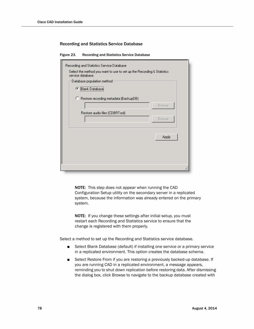
Cisco CAD Installation Guide
Recording and Statistics Service Database
Figure 23. Recording and Statistics Service Database
NOTE: This step does not appear when running the CAD Configuration Setup utility on the secondary server in a replicated system, because the information was already entered on the primary system.
NOTE: If you change these settings after initial setup, you must restart each Recording and Statistics service to ensure that the change is registered with them properly.
Select a method to set up the Recording and Statistics service database.
■ Select Blank Database (default) if installing one service or a primary service in a replicated environment. This option creates the database schema.
■ Select Restore From if you are restoring a previously backed-up database. If you are running CAD in a replicated environment, a message appears, reminding you to shut down replication before restoring data. After dismissing the dialog box, click Browse to navigate to the backup database created with
78 August 4, 2014

the BackupDB and CDBRTool utilities. When you go to the next step, a message appears, reminding you to re-establish replication after the restore. For more information, see "Backup and Restore" on page 126.
NOTE: You can restore recording metadata without restoring audio files, but you cannot restore audio files without recording metadata.
August 4, 2014 79
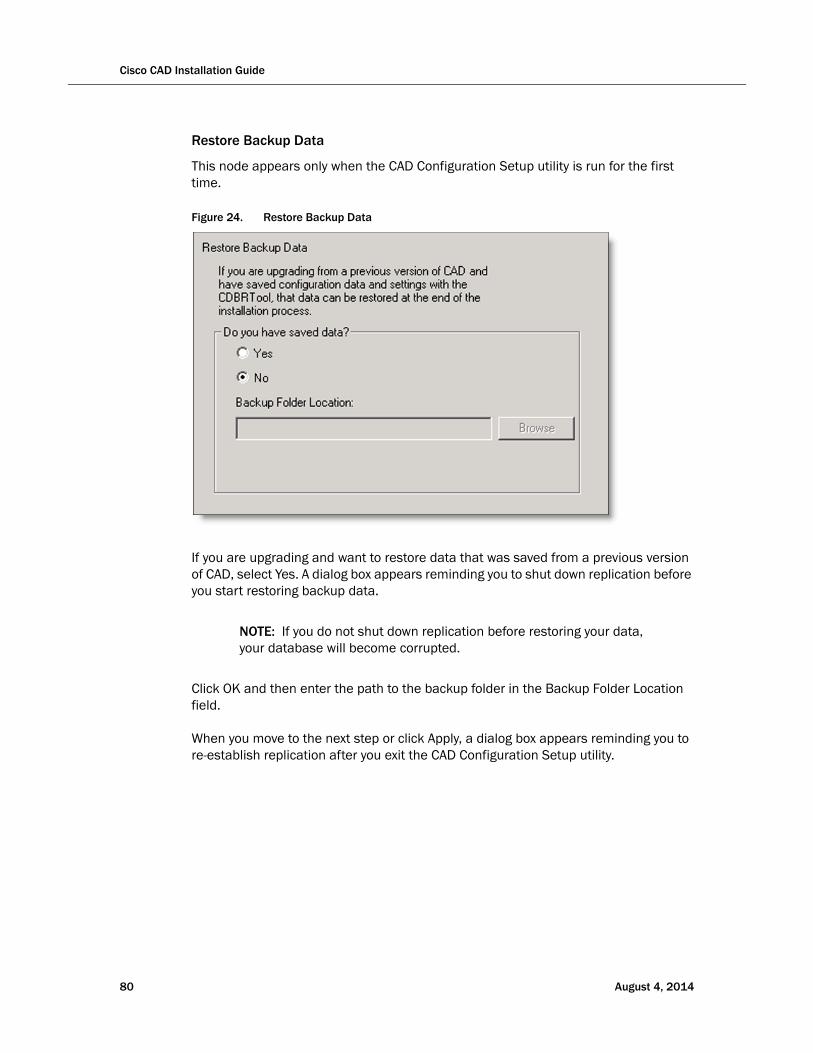
Cisco CAD Installation Guide
80 August 4, 2014
Restore Backup Data
This node appears only when the CAD Configuration Setup utility is run for the first time.
Figure 24. Restore Backup Data
If you are upgrading and want to restore data that was saved from a previous version of CAD, select Yes. A dialog box appears reminding you to shut down replication before you start restoring backup data.
NOTE: If you do not shut down replication before restoring your data, your database will become corrupted.
Click OK and then enter the path to the backup folder in the Backup Folder Location field.
When you move to the next step or click Apply, a dialog box appears reminding you to re-establish replication after you exit the CAD Configuration Setup utility.
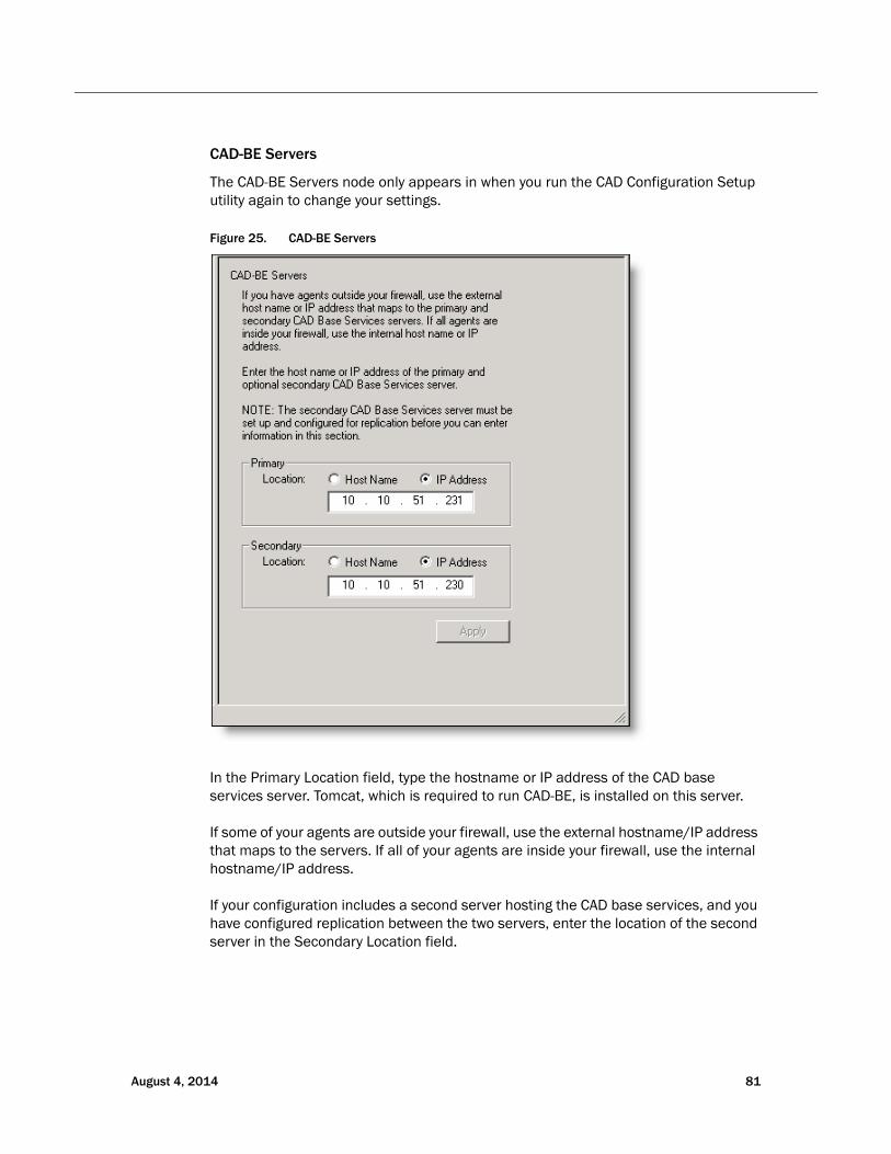
CAD-BE Servers
The CAD-BE Servers node only appears in when you run the CAD Configuration Setup utility again to change your settings.
Figure 25. CAD-BE Servers
In the Primary Location field, type the hostname or IP address of the CAD base services server. Tomcat, which is required to run CAD-BE, is installed on this server.
If some of your agents are outside your firewall, use the external hostname/IP address that maps to the servers. If all of your agents are inside your firewall, use the internal hostname/IP address.
If your configuration includes a second server hosting the CAD base services, and you have configured replication between the two servers, enter the location of the second server in the Secondary Location field.
August 4, 2014 81

Cisco CAD Installation Guide
NOTE: If you are changing configuration settings and established replication in the first run of the CAD Configuration Setup utility, the Secondary Location field is filled automatically.
NOTE: The Secondary Location is not enabled until you configure the second CAD base services server and establish replication.
82 August 4, 2014
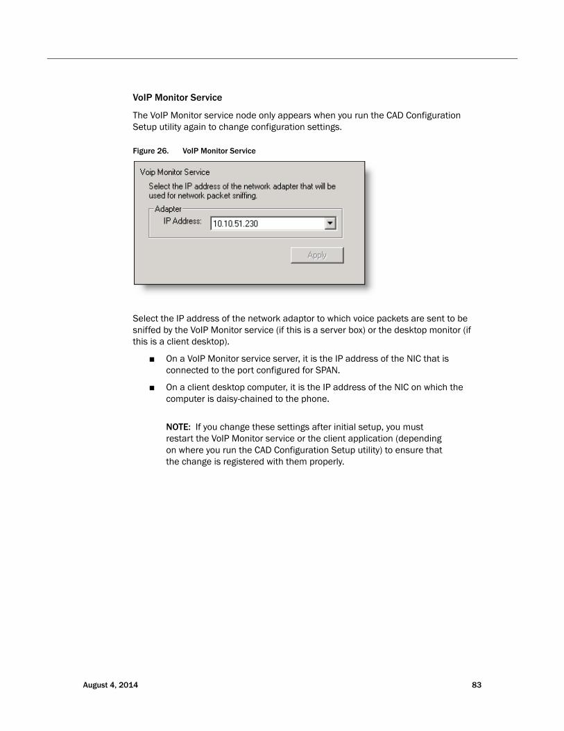
August 4, 2014 83
VoIP Monitor Service
The VoIP Monitor service node only appears when you run the CAD Configuration Setup utility again to change configuration settings.
Figure 26. VoIP Monitor Service
Select the IP address of the network adaptor to which voice packets are sent to be sniffed by the VoIP Monitor service (if this is a server box) or the desktop monitor (if this is a client desktop).
■ On a VoIP Monitor service server, it is the IP address of the NIC that is connected to the port configured for SPAN.
■ On a client desktop computer, it is the IP address of the NIC on which the computer is daisy-chained to the phone.
NOTE: If you change these settings after initial setup, you must restart the VoIP Monitor service or the client application (depending on where you run the CAD Configuration Setup utility) to ensure that the change is registered with them properly.
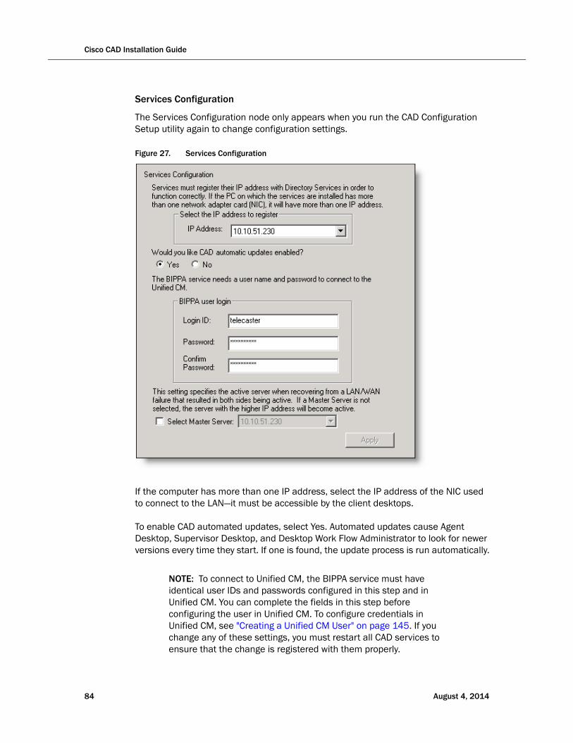
Cisco CAD Installation Guide
Services Configuration
The Services Configuration node only appears when you run the CAD Configuration Setup utility again to change configuration settings.
Figure 27. Services Configuration
If the computer has more than one IP address, select the IP address of the NIC used to connect to the LAN—it must be accessible by the client desktops.
To enable CAD automated updates, select Yes. Automated updates cause Agent Desktop, Supervisor Desktop, and Desktop Work Flow Administrator to look for newer versions every time they start. If one is found, the update process is run automatically.
NOTE: To connect to Unified CM, the BIPPA service must have identical user IDs and passwords configured in this step and in Unified CM. You can complete the fields in this step before configuring the user in Unified CM. To configure credentials in Unified CM, see "Creating a Unified CM User" on page 145. If you change any of these settings, you must restart all CAD services to ensure that the change is registered with them properly.
84 August 4, 2014

If your system is High Availability over WAN/LAN, and you want to designate a master server, select the Select Master Server check box and then choose the appropriate IP address from the drop-down list.
NOTE: If the WAN link goes down, both servers think that the other server is down and try to take over as master server. When the link is restored, this setting dictates which server is the master and which server is on standby.
August 4, 2014 85
Cisco CAD Installation Guide
SNMP Configuration
The SNMP Configuration step appears only if you are running the CAD Configuration Setup utility again to change configuration settings and if the Simple Network Management Protocol (SNMP) service is installed on the server that hosts the CAD base services.
SNMP allows you to monitor and manage a network from a single workstation or several workstations, called SNMP managers. SNMP is actually a family of specifications that provide a means for collecting network management data from the devices residing in a network. It also provides a method for those devices to report any problems they are experiencing to the management station.
When CAD is not running on a PG, configure the Microsoft SNMP service.
When CAD is running on a PG, Cisco SNMP Agent Management service must be enabled and the Microsoft SNMP service must be disabled. The Microsoft SNMP service and the Cisco SNMP Agent Management service cannot simultaneously be enabled.
For more information on installing the Microsoft SNMP service and the Cisco SNMP Agent Management service, see "Desktop Monitoring Console" on page 153.
86 August 4, 2014
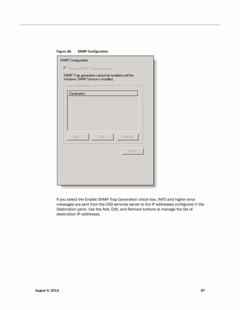
If you select the Enable SNMP Trap Generation check box, INFO and higher error messages are sent from the CAD services server to the IP addresses configured in the Destination pane. Use the Add, Edit, and Remove buttons to manage the list of destination IP addresses.
Figure 28. SNMP Configuration
August 4, 2014 87
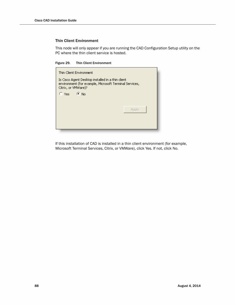
Cisco CAD Installation Guide
88 August 4, 2014
Thin Client Environment
This node will only appear if you are running the CAD Configuration Setup utility on the PC where the thin client service is hosted.
Figure 29. Thin Client Environment
If this installation of CAD is installed in a thin client environment (for example, Microsoft Terminal Services, Citrix, or VMWare), click Yes. If not, click No.
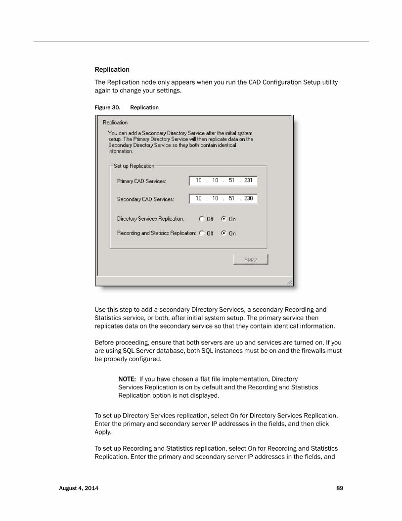
Replication
The Replication node only appears when you run the CAD Configuration Setup utility again to change your settings.
Figure 30. Replication
Use this step to add a secondary Directory Services, a secondary Recording and Statistics service, or both, after initial system setup. The primary service then replicates data on the secondary service so that they contain identical information.
Before proceeding, ensure that both servers are up and services are turned on. If you are using SQL Server database, both SQL instances must be on and the firewalls must be properly configured.
NOTE: If you have chosen a flat file implementation, Directory Services Replication is on by default and the Recording and Statistics Replication option is not displayed.
To set up Directory Services replication, select On for Directory Services Replication. Enter the primary and secondary server IP addresses in the fields, and then click Apply.
To set up Recording and Statistics replication, select On for Recording and Statistics Replication. Enter the primary and secondary server IP addresses in the fields, and
August 4, 2014 89

Cisco CAD Installation Guide
then click Apply. A dialog box appears, prompting you to enter the primary server hostname for Recording and Statistics replication. Enter the hostname, then click OK. Another dialog box appears, prompting you to enter the secondary server hostname for Recording and Statistics replication. Enter the hostname, then click OK.
NOTE: If you changed the Database Directory field on the Recording and Statistics Database Configuration node to a database directory that is not the default you must change it on both servers. It will not populate automatically to the other server.
This change must be applied to both servers before proceeding with Recording and Statistics replication.
For more information on replication issues, refer to the Cisco CAD Troubleshooting Guide.
90 August 4, 2014
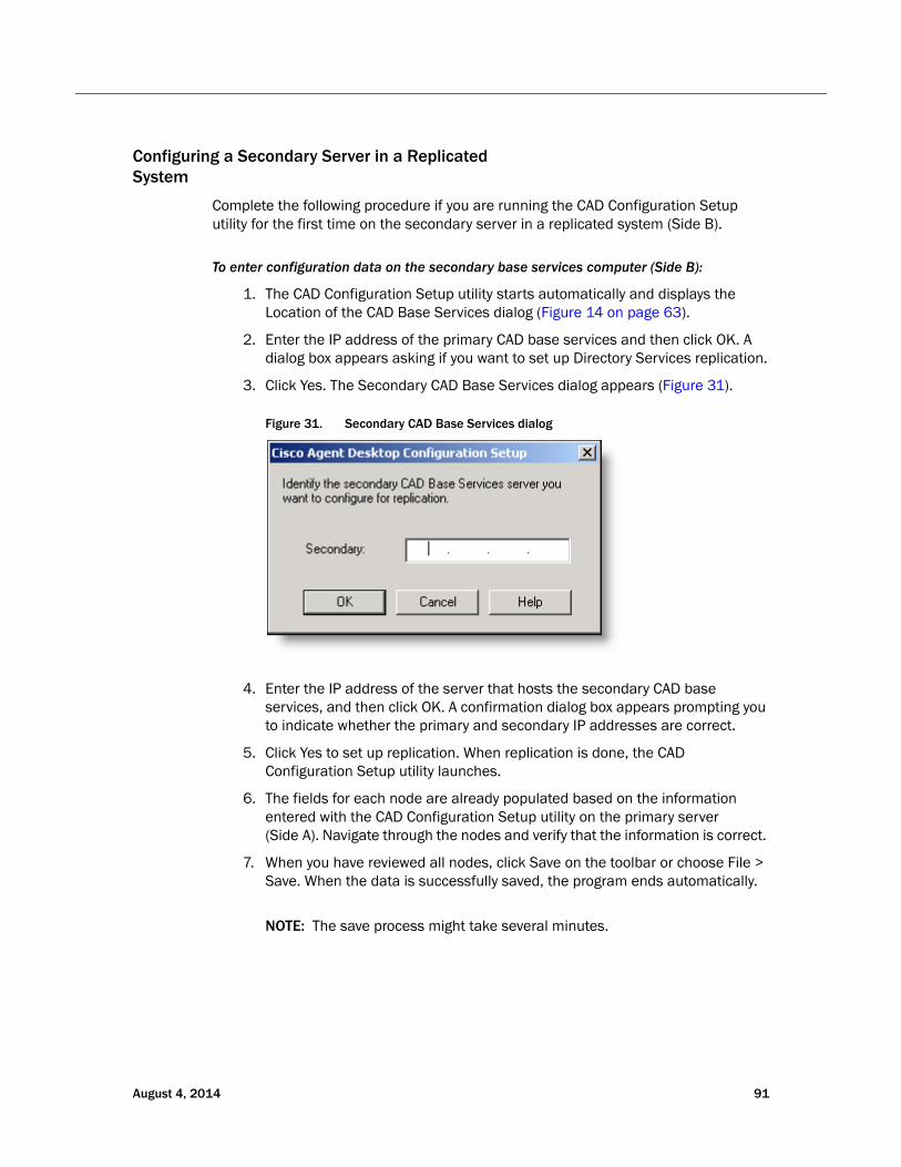
August 4, 2014 91
Configuring a Secondary Server in a Replicated System
Complete the following procedure if you are running the CAD Configuration Setup utility for the first time on the secondary server in a replicated system (Side B).
To enter configuration data on the secondary base services computer (Side B):
1. The CAD Configuration Setup utility starts automatically and displays the Location of the CAD Base Services dialog (Figure 14 on page 63).
2. Enter the IP address of the primary CAD base services and then click OK. A dialog box appears asking if you want to set up Directory Services replication.
3. Click Yes. The Secondary CAD Base Services dialog appears (Figure 31).
Figure 31. Secondary CAD Base Services dialog
4. Enter the IP address of the server that hosts the secondary CAD base services, and then click OK. A confirmation dialog box appears prompting you to indicate whether the primary and secondary IP addresses are correct.
5. Click Yes to set up replication. When replication is done, the CAD Configuration Setup utility launches.
6. The fields for each node are already populated based on the information entered with the CAD Configuration Setup utility on the primary server (Side A). Navigate through the nodes and verify that the information is correct.
7. When you have reviewed all nodes, click Save on the toolbar or choose File > Save. When the data is successfully saved, the program ends automatically.
NOTE: The save process might take several minutes.
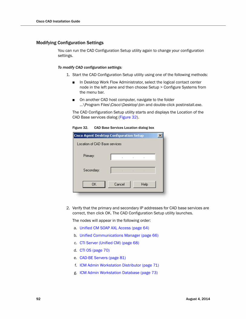
Cisco CAD Installation Guide
Modifying Configuration Settings
You can run the CAD Configuration Setup utility again to change your configuration settings.
To modify CAD configuration settings:
1. Start the CAD Configuration Setup utility using one of the following methods:
■ In Desktop Work Flow Administrator, select the logical contact center node in the left pane and then choose Setup > Configure Systems from the menu bar.
■ On another CAD host computer, navigate to the folder …\Program Files\Cisco\Desktop\bin and double-click postinstall.exe.
The CAD Configuration Setup utility starts and displays the Location of the CAD Base services dialog (Figure 32).
Figure 32. CAD Base Services Location dialog box
2. Verify that the primary and secondary IP addresses for CAD base services are correct, then click OK. The CAD Configuration Setup utility launches.
The nodes will appear in the following order:
a. Unified CM SOAP AXL Access (page 64)
b. Unified Communications Manager (page 66)
c. CTI Server (Unified CM) (page 68)
d. CTI OS (page 70)
e. CAD-BE Servers (page 81)
f. ICM Admin Workstation Distributor (page 71)
g. ICM Admin Workstation Database (page 73)
92 August 4, 2014

h. Recording and Statistics Database Configuration (page 75)
i. Recording and Statistics Service Database (page 78)
j. VoIP Monitor Service (page 83)
k. Services Configuration (page 84)
l. Replication (page 89)
NOTE: To switch between the left and right pane, press F6. To move up and down the left pane, use the up and down arrows.
3. Select the node you want to modify from the left pane, enter the new data in the right pane, and then click Apply.
■ You can access the nodes in any order.
■ If you modify something in a node, you must click Apply to save your changes before you move on to another node.
4. When you are done making your changes, choose File > Exit or click Close. The CAD Configuration Setup utility closes.
5. Restart the CAD base services and all desktops for your changes to take effect.
August 4, 2014 93
Cisco CAD Installation Guide
Licensing CAD 9.0
After you have installed and configured CAD, Unified CCE License Administration automatically starts. You can license your software at this point or close the application and license your software later. Your CAD software will not run until you have licensed your CAD services. You can re-run Unified CCE License Administration whenever you want to update the number of seats you have purchased.
NOTE: Current licenses persist when upgrades are made on existing or new servers. No new licenses are required.
NOTE: Licensing your software can only be completed by a Cisco channel partner or Cisco Professional Services.
Obtaining a License Account
You must obtain a license account user ID and password to license your software.
To obtain a license account:
1. Open Internet Explorer.
2. Navigate to the following address:
http://cadlicensing.com/sws/WebLicensingInitial/InitialLicensePage.html
3. Click the Create a License Account hyperlink.
4. Complete the Partner License Request Form, then click E-mail Request. After your request is processed, your user ID and password will be e-mailed to you.
94 August 4, 2014
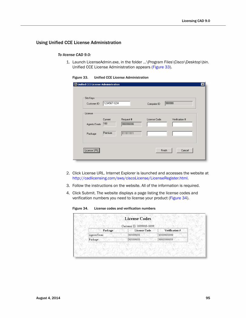
Licensing CAD 9.0
Using Unified CCE License Administration
To license CAD 9.0:
1. Launch LicenseAdmin.exe, in the folder …\Program Files\Cisco\Desktop\bin. Unified CCE License Administration appears (Figure 33
Figure 33. Unified CCE License Administration
).
2. Click License URL. Internet Explorer is launched and accesses the website at http://cadlicensing.com/sws/ciscoLicense/LicenseRegister.html.
3. Follow the instructions on the website. All of the information is required.
4. Click Submit. The website displays a page listing the license codes and verification numbers you need to license your product (Figure 34).
Figure 34. License codes and verification numbers
August 4, 2014 95

Cisco CAD Installation Guide
5. Enter the Customer ID, License Codes, and Verification numbers in Unified CCE License Administration, then click Finish. All of the licensed applications are activated.
Recording Licenses
Recording & Playback are licensed features. The number of licenses available is determined by the type of bundle you purchase:
■ Standard: no license
■ Enhanced: 32 licenses
■ Premium: 80 licenses
A license is used whenever a supervisor or agent triggers the recording function, and is released when the recording is stopped. A license is also used when a supervisor opens the Supervisor Record Viewer, and is released when the Supervisor Record Viewer is closed.
If all licenses are in use:
■ Agents and supervisors cannot record calls
■ Supervisors cannot open Supervisor Record Viewer and an error message saying that a licensing error has occurred is displayed
96 August 4, 2014

Modifying the Peripheral Gateway Registry
Modifying the Peripheral Gateway Registry
A registry key on the peripheral gateway (PG) computer must be modified so that the Agent Desktop call activity pane displays the correct amount of time a caller spends at Intelligent Voice Recognition (IVR).
You must complete this modification after the CAD base services have been installed.
To modify the PG computer registry key:
1. On the PG computer where CAD base services are installed, open the Windows Registry Editor (regedit).
2. Navigate to the following key:
HKEY_LOCAL_MACHINE\SOFTWARE\Wow6432Node\Cisco Systems, Inc.\ICM\ <ICM instance>\PG <PG number>\PG\CurrentVersion\OPC\CallControl\ pim <PIM number>\NewCallOffersUpdateDNIS
3. Change the value of NewCallOffersUpdateDNIS to 1.
4. Repeat steps 2 and 3 for each PIM number.
5. Close the Windows Registry Editor.
August 4, 2014 97

Cisco CAD Installation Guide
98 August 4, 2014
August 4, 2014
CAD Desktop Client Applications
Configuring CAD Client MSI Files
Overview
CAD dynamically creates its installation and maintenance release packages for the agent, supervisor, and administrator desktop client applications during the course of installing or upgrading the CAD base services on the host (typically a peripheral gateway). The resulting CAD MSI packages are located on the production server in this location:
C:\Program Files (x86)\Cisco\Desktop\Tomcat\webapps\TUP\CAD
The MSI files stored in this folder are intended for use in both manual and automated deployments. The benefit of creating the install packages within the context of the server-side installation is that the resulting client MSIs include deployment-specific information (such as server host IP address and language selection) that facilitate a silent client-side installation.
However, in environments where a deployment partner or customer intends to use a third party automated package distribution tool (such as Microsoft System Configuration Manager), access to the CAD MSI packages is frequently needed before performing the CAD server-side installation.
To accommodate these requirements, two new features have been added to CAD 9.0:
■ For base releases, a client configuration package containing an MSI configuration tool on the CAD 9.0 media that can be used independently of the server installation package
■ For maintenance releases (MRs) and engineering specials (ESs), an MSI that is posted on the Cisco website
99
Cisco CAD Installation Guide
Client MSI Preparation Procedure for Base Releases
The client configuration package includes an MSI configuration tool and a stand-alone directory structure. The MSI configuration tool prompts the deployment engineer to provide the environment-specific configuration data, and then interacts with the files in the stand-alone directory to create the CAD client MSI.
To use the client configuration package to generate configured MSI installation packages:
1. Copy the Client folder from the source DVD to any location on a Microsoft Windows XP, Windows Vista, or Windows 7 computer. The folder includes the following subfolders and utility:
■ Administrator (folder)
■ Agent (folder)
■ Supervisor (folder)
■ ConfigureMSI.exe
2. Navigate to the folder and double-click ConfigureMSI.exe to launch the MSI configuration tool.
3. Provide the configuration data prompted for by the tool. You are asked for the following information:
■ Language of the contact center
■ IP address of CAD’s LDAP Host 1
■ IP address of CAD’s LDAP Host 2 (or ‘none’ if the system is not duplex)
NOTE: LDAP Host 1 and LDAP Host 2 do not necessarily correspond to Peripheral Gateway A and Peripheral Gateway B. Rather, these are the servers that will be designated as the primary and secondary CAD base services servers in the CAD Configuration Setup utility during the CAD server configuration process. See "CAD Configuration Setup Utility" on page 60 for further details.
4. The client MSI packages, now containing the specified language and IP addresses, appear in the folder where ConfigureMsi.exe is located. The file names are:
■ Cisco Agent Desktop.msi
■ Cisco Supervisor Desktop.msi
■ Cisco Desktop Administrator.msi
5. Validate the client installation packages by installing the application on a compatible test PC. This can be a new installation or over a previous CAD 7.x release. The installation screens should appear in the selected language.
100 August 4, 2014
Configuring CAD Client MSI Files
■ An inspection of the registry key HKEY_LOCAL_MACHINE\SOFTWARE\Wow6432Node\Calabrio\CAD\Site Setup should reflect the specified LDAP Host 1 and LDAP Host 2 entries.
■ CAD desktop applications should appear in the Add or Remove Programs utility in the Windows Control Panel. If you click the “Click here for support information” link for the application, you should see the correct version number.
NOTE: Because the client and server versions must match, it is not possible to validate the client MSIs by launching the application and logging into the system as an agent or supervisor prior to performing the server-side installation.
6. Once validated, you can create the automated deployment packages in accordance with the requirements listed in the section, "Using Automated Package Distribution Tools" on page 103. Otherwise, the client installation packages can be deployed manually.
Client MSIs for Maintenance Releases and Engineering Specials
The client MSI for MRs and ESs can be obtained two ways.
■ When the executable for installing the server MR or ES is run:
— The client MSI is extracted and placed in the C:\Program Files (x86)\Cisco\Desktop\Tomcat\webapps\TUP\CAD folder
— The web page http://<CAD server>:8088/TUP/CAD/Patches.htm, which is created when the first MR or ES is installed on the server, is updated with a link to the client MSI
■ The client MSI can be downloaded from the Cisco website.
The MR or ES server executable is named as follows:
■ CAD_[<version>]_MR<version>ES<version>_setup.exe
The MR or ES client MSIs are named as follows:
■ Cisco Desktop Services <version> Maintenance Release <version>.msi
■ Cisco Desktop Services <version> Maintenance Release <version> Engineering Special <version>.msi
NOTE: The name of the client MSI you download from the Cisco website is named differently than the client MSI extracted from the
August 4, 2014 101

Cisco CAD Installation Guide
MR or ES executable. The download file name is Cisco_Agent_Desktop_Client_for_Unified_CCE_[<version>]_Installer.msi.
The MR or ES can be applied to client desktops in any of three ways:
Automatic Update. If the Automated Updates feature is enabled, the client desktop will update automatically the next time the client application is started. This process uses the client MSI automatically placed on the CAD base services server when the MR or ES was applied to the servers. This method requires that the user have administrator privileges on the client PC.
Manual Update. You can manually update each client desktop by copying the client MSI file from the CAD base services server, downloading it from the Cisco website, or running it from the link on the Patches.htm web page. This method requires that the user has administrator privileges on the client PC.
Pushing Update. You can use a third party automated package distribution tool to push the client MSI to client desktops. Since the push package is often prepared and tested in advance of applying the MR or ES to the CAD servers, you can download the client MSI from the Cisco website at any time. See "Using Automated Package Distribution Tools" on page 103 for more information on push packages.
102 August 4, 2014
Using Automated Package Distribution Tools
Using Automated Package Distribution Tools
CAD’s MSI-based desktop application installations can be deployed (“pushed”) via automated package distribution tools that make use of the Microsoft Windows Installer service.
If you need to create MSIs before the CAD base services are installed, see "Configuring CAD Client MSI Files" on page 99.
Requirements
CAD support for automated package distribution depends on compliance with the requirements listed below.
Execution
Installations must be executed on the target machine. Deployment methods that capture a snapshot of an installation and redistribute that image are not supported.
Per-Machine vs. Per-User Installation
Installations must be deployed on a per-machine basis. Per-user installations are not supported.
It might be necessary to ensure per-machine installation via command line.
Privileges
By default, Windows Installer installations run in the context of the logged-on user. CAD installations, which use Windows Installer, require either administrative or elevated (system) privileges. If the CAD installation is run in the context of an administrative account, no additional privileges are required.
If the CAD installation is run in the context of an account with reduced privileges, the Windows policy “Always Install with Elevated Privileges” must be enabled to deploy the installation with elevated privileges.
When this policy is enabled, Windows Installer installations will run in a context with elevated privileges, thus allowing the installation to successfully complete complex tasks that require a privilege level beyond that of the logged-on user.
To direct Windows Installer to use elevated privileges, launch the Microsoft Management Console (MMC) Local Computer Policy snap-in on the target machine. Enable the Windows policy “Always Install with Elevated Privileges” for both the Computer Configuration and the User Configuration nodes.
For more information about enabling this policy, see “Always install with elevated privileges” at:
August 4, 2014 103
Cisco CAD Installation Guide
http://msdn2.microsoft.com/en-us/library/ms813108.aspx
Automated Package Installation vs. Manual Installation
Automated installations must use the same files and meet the same installation criteria as manually-deployed installations.
CAD MSI packages are located in a specified location (the folder C:\Program Files (x86)\Cisco\Desktop\Tomcat\webapps\TUP\CAD) on a successfully-installed production server and are intended for both manual and automated deployment. Alteration of these files or the use of other MSI files included with the product at other locations is not supported.
Installation criteria such as supported operating systems, product deployment configurations, installation order, and server/client version synchronization must be met. Altering the supplied MSI packages to circumvent the installation criteria is not supported.
Multiple Software Releases
Multiple software releases must not be combined into a single deployment package. Each CAD software release is intended for distribution in its entirety as a distinct deployment. Combining multiple releases (for example, a software package's base release and a subsequent service release) into a single deployment package is not supported.
Reboots
Any reboots associated with CAD installations are required. If the installation’s default reboot behavior is suppressed, the target machine must be rebooted before running the installed applications to ensure expected functionality.
Delaying a reboot is not known to be an issue at this time, as long as a reboot occurs before launching the installed applications. If it is determined in the future that delaying a reboot via command line suppression affects expected behavior, then that delayed reboot will not be supported.
Best Practices
Best practices recommendations are listed below.
Windows Installer Logging
To ensure that any loggable issues are captured efficiently, enable Window Installer logging using the following command line argument:
Install from an EXE file: /V“/l*v<logfile path and name>”
Install from an MSI: /l*v <logfile path and name>
104 August 4, 2014
Using Automated Package Distribution Tools
NOTE: The logfile path and name must be a location to which the installation’s user context has permission to write.
Deployment
Each installation package should be deployed using its own deployment package. Using separate packages offers faster isolation of potential issues than does a composite deployment package.
Installation and Uninstallation Deployment Packages
The deployment engineer should create and test both an installation and uninstallation deployment package.
This is especially important for service release installations, which must be uninstalled before upgrading the underlying software.
Recommended Deployment Preparation Model
1. Use a lab environment to model the pending deployment.
2. Install the servers to obtain valid client installation packages.
3. Manually deploy client installation packages to ensure that the installs are compatible with your environment. This will isolate product installation vs. automated deployment issues.
4. Create your deployment packages in accordance with the requirements listed in "Requirements" on page 103.
5. Test the deployment packages.
6. At deployment time modify your deployment packages, replacing the client installation packages from the lab environment with valid client installation packages from the production server.
August 4, 2014 105
Cisco CAD Installation Guide
Installing Desktop Applications
Desktop Administrator, Supervisor Desktop, and Agent Desktop are installed from web pages that are created during the CAD base services installation. The web pages are located on servers that host the CAD base services.
CAD-BE is a Java applet that runs on the agent’s desktop and is downloaded from the server hosting the CAD base services. It is accessed by agents through their Windows Internet Explorer or Mozilla Firefox browser. The Java Runtime Environment (JRE) browser plug-in must be installed on each agent’s computer.
NOTE: You cannot install the desktop applications on the CAD server unless you are running CAD in a thin client environment. For more information, see "Thin Client Environments" on page 27.
Desktop users must have either administrator or elevated privileges to install the CAD desktop applications. If you want users with limited privileges to their computer to be able to install a desktop application, you must enable the Windows policy “Always Install with Elevated Privileges” on their computers. This also applies to installations pushed to the desktop via an automated package distribution tool. For more information about enabling this policy, see "Privileges" on page 103.
Client Installation Failure
If the installation program for any CAD client application will not run, and you receive the error message, “This installation is not fully configured. See product documentation for properly configuring your system”, it means that the installation programs are not correctly configured through the CAD Configuration Setup utility. You must reconfigure the client installation programs.
To correct this problem, complete the following procedure.
NOTE: In a redundant configuration, you must complete this procedure on the primary and secondary CAD base services servers.
To reconfigure CAD client installation programs:
1. Run the CAD Configuration Setup utility on the CAD base services server (see "Modifying Configuration Settings" on page 92 for instructions on how to start it).
2. From the menu, choose File > Reset Client Installs. This process reconfigures the client installation programs.
3. When the process is complete, the message, “Client installs reset” is displayed. Click OK to close the message. You can now install the client applications from the installation web pages.
106 August 4, 2014
Installing Desktop Applications
Error/Event and Debug Logs
The CAD event/error and debugging logs can help you discover where problems exist if you experience difficulties in installing the CAD desktop applications. You must enable logging from the command line prompt for all new installs and most upgrade scenarios. The exception to this requirement is the client-side automated update feature.
For detailed information on logs and debugging, see Chapter 4, “Logs and Debugging”, in the Cisco CAD Troubleshooting Guide.
Installing Desktop Administrator
To install Desktop Administrator:
1. From the desktop on which you want to install Desktop Administrator, access the following URL, where <CAD server> is the IP address of the server on which the CAD base services are installed.
http://<CAD server>:8088/TUP/CAD/Admin.htm
The Desktop Administrator installation web page appears.
2. Follow the instructions on the web page to install the application.
Installing Agent Desktop and Supervisor Desktop
To install Agent Desktop and Supervisor Desktop:
1. From the desktop on which you want to install Agent Desktop or Supervisor Desktop, access the following URL, where <CAD server> is the IP address of the server on which the CAD base services are installed:
http://<CAD server>:8088/TUP/CAD/Install.htm
The Agent Desktop, Supervisor Desktop, and Agent Desktop—Browser Edition Installation web page appears.
2. Follow the instructions on the web page to install the selected application.
Installation Notes
■ When you install Supervisor Desktop, Agent Desktop is installed automatically. Both applications are needed for a supervisor to use all the functionality of Supervisor Desktop.
■ If you attempt to install Supervisor Desktop on a computer that already hosts Agent Desktop, you will receive error messages that a conflicting application has been detected. You must first uninstall Agent Desktop to avoid this.
August 4, 2014 107
Cisco CAD Installation Guide
Configuring CAD-BE
The CAD-BE Java applet is installed when the BIPPA service is installed, on the same computer as the BIPPA service.
In order to run CAD-BE in an agent’s browser, the Java Runtime Environment (JRE) plug-in for Internet Explorer or Firefox (Windows) or for Firefox (Linux) must be installed.
See "Internet Explorer Settings for CAD-BE" and "Firefox Settings for CAD-BE" for information on how to configure your web browser to run CAD-BE.
To install the JRE plug-in:
1. From the desktop where you wish to install the JRE plug-in, access the following URL, where <CAD server> is the IP address of the server on which the CAD base services are installed:
http://<CAD server>:8088/TUP/CAD/Install.htm
2. The Agent Desktop, Supervisor Desktop, and Agent Desktop—Browser Edition Installation web page appears.
3. From the CAD-BE section, download the appropriate version of JRE for your operating system (Windows or Linux).
4. Click the appropriate installation instructions hyperlink and complete the procedure that corresponds to your operating system.
If the correct version of JRE already exists on the agent desktop, you will see a message telling you this and the installation will not proceed. If an older or newer version of JRE than the version required exists on the agent’s PC, the installation proceeds with no messages displayed.
Internet Explorer Settings for CAD-BE
The following settings must be configured in Internet Explorer in order for CAD-BE to run successfully.
Pop-up Blocker
Disable the pop-up blocker, or create an exception to enable pop-ups from the CAD-BE IP address:
■ Choose Tools > Pop-up Blocker > Turn Off Pop-up Blocker.
OR
■ Choose Tools > Pop-up Blocker > Pop-up Blocker Settings and add the CAD-BE IP address(es) to the list of allowed sites.
108 August 4, 2014

Installing Desktop Applications
Internet Options
Set the following internet options:
1. Choose Tools > Internet Options and select the Security tab.
2. Click Custom Level.
3. In the Settings pane, set the following options:
■ Under the ActiveX controls and plug-ins section, set Run ActiveX controls and plug-ins to Enable.
■ Under the Miscellaneous section, set Launching programs and files in an IFRAME to Prompt or Enable.
■ Under the Scripting section, set Active Scripting to Enable.
Internet Explorer 7 and 8 Security Feature
Internet Explorer 7 and 8 has a security feature that places a non-editable address bar directly below the title bar in the CAD-BE interface.
To remove the address bar:
1. Choose Tools > Internet Options.
2. Select the Security tab and select either the Local intranet zone or the Trusted sites zone.
3. Click Sites, then click Add. This adds the CAD-BE web site to the zone you selected. (The Local intranet and Trusted sites zones have the setting “Allow websites to open windows without address or status bars” enabled.
Firefox Settings for CAD-BE
The following settings must be configured in Firefox in order for CAD-BE to run successfully.
NOTE: The Preferences window in Firefox for Linux is the same as the Options window in Firefox for Windows. To access Preferences in Firefox for Linux, choose Edit > Preferences.
Pop-up Blocker
You can either disable the pop-up blocker or create an exception to enable pop-ups from the CAD server.
To disable the pop-up blocker:
1. Choose Tools > Options > Content.
2. Deselect Block Popup Windows.
August 4, 2014 109

Cisco CAD Installation Guide
To create an exception to enable pop-ups from the CAD server:
1. Choose Tools > Options > Content.
2. Click Allowed Sites and add the IP address(es) of the CAD server to the list of allowed sites.
Content Settings
Configure the following settings:
1. Choose Tools > Options > Content, and select the following check boxes:
■ Enable Java
■ Enable JavaScript
2. Next to the Enable JavaScript check box, click Advanced and select these check boxes in the Advanced JavaScript Settings dialog box:
■ Raise or lower windows
■ Disable or replace context menus
3. In the browser address field, type the following:
about:config
4. Locate the preference dom.allow_scripts_to_close_windows.
5. Right-click the preference and select Toggle to set the value to True.
110 August 4, 2014
August 4, 2014
Upgrading from a Previous Version of CAD
Overview
Before you upgrade from a previous version of CAD, it is recommended that you read the CAD 9.0 release notes. Release notes are available at:
http://www.cisco.com/en/US/products/sw/custcosw/ps1844/prod_release_notes_list.html
Table 11 contains upgrade paths. Starting at the left column choose your current operating system. Choose the version of CAD from which you are upgrading and the data store method you are currently using. Then choose the data storage method you would like to use with CAD 9.0.
111
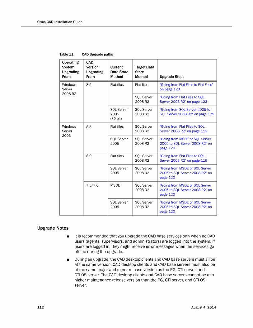
Cisco CAD Installation Guide
Upgrade Notes
■ It is recommended that you upgrade the CAD base services only when no CAD users (agents, supervisors, and administrators) are logged into the system. If users are logged in, they might receive error messages when the services go offline during the upgrade.
■ During an upgrade, the CAD desktop clients and CAD base servers must all be at the same version. CAD desktop clients and CAD base servers must also be at the same major and minor release version as the PG, CTI server, and CTI OS server. The CAD desktop clients and CAD base servers cannot be at a higher maintenance release version than the PG, CTI server, and CTI OS server.
Table 11. CAD Upgrade paths
Operating System Upgrading From
CAD Version Upgrading From
Current Data Store Method
Target Data Store Method Upgrade Steps
Windows Server 2008 R2
8.5 Flat files Flat files "Going from Flat Files to Flat Files" on page 123
SQL Server 2008 R2
"Going from Flat Files to SQL Server 2008 R2" on page 123
SQL Server 2005 (32-bit)
SQL Server 2008 R2
"Going from SQL Server 2005 to SQL Server 2008 R2" on page 125
Windows Server 2003
8.5 Flat files SQL Server 2008 R2
"Going from Flat Files to SQL Server 2008 R2" on page 119
SQL Server 2005
SQL Server 2008 R2
"Going from MSDE or SQL Server 2005 to SQL Server 2008 R2" on page 120
8.0 Flat files SQL Server 2008 R2
"Going from Flat Files to SQL Server 2008 R2" on page 119
SQL Server 2005
SQL Server 2008 R2
"Going from MSDE or SQL Server 2005 to SQL Server 2008 R2" on page 120
7.5/7.6 MSDE SQL Server 2008 R2
"Going from MSDE or SQL Server 2005 to SQL Server 2008 R2" on page 120
SQL Server 2005
SQL Server 2008 R2
"Going from MSDE or SQL Server 2005 to SQL Server 2008 R2" on page 120
112 August 4, 2014
Overview
■ Reason codes are created and maintained in Unified ICM. Any reason codes that you created using Desktop Work Flow Administrator in previous versions of CAD will be lost in an upgrade. To continue using these reason codes, re-create them in Unified ICM.
■ All reserved reason codes are automatically enabled in CAD 9.0.
■ Enterprise data fields and field layouts are created and customized in Cisco Desktop Administrator (Services Configuration > Enterprise Data > Fields). If you edited default Enterprise data fields or layouts, then your changes will be lost after an upgrade. The default fields will revert back and must be re-configured after an upgrade. However, any custom fields that you created will remain after an upgrade.
■ All phone books (personal, work flow group, and global) are preserved during an upgrade.
■ Wrap-up data from previous CAD versions will be enabled at the work flow group level and disabled at the global level. It can be enabled later at the global level as needed.
■ If you changed the IP address of any server in your configuration after you backed up data, you must run the CAD Configuration Setup utility and enter the current IP addresses after you have restored your data, because the old IP addresses will be restored.
■ If you changed the IP address of a Base Services server as part of your upgrade, the new IP addresses will not be propagated to the client machines if the client software is applied over the top of existing software. In over the top upgrade scenarios, the client installer preserves a number of configuration settings including the IP addresses of the Base Services servers. To apply the new settings to the clients, the registry must be changed either before or after the over the top upgrade.
To change the registry, locate HKEY_LOCAL_MACHINE\SOFTWARE\Calabrio\CAD\Site Setup and match the client’s values for LDAP Host 1 and LDAP Host 2 to the values on the Base Services servers.
Alternatively, in order to avoid changing the registry, you can also uninstall the existing client software prior to installation of the newer version.
■ If you modified the default Enterprise Data Layout in previous versions of CAD, your changes will be lost in an upgrade. You must re-configure the default Enterprise Data Layout once the upgrade is completed.
Upgrading Replicated Systems
If you are upgrading a replicated system, you must shut down replication on both servers before you begin the upgrade process. If you do not do this, your CAD services LDAP database will become corrupted. For instructions, see "Shutting Down and Restarting Replication" on page 157.
August 4, 2014 113
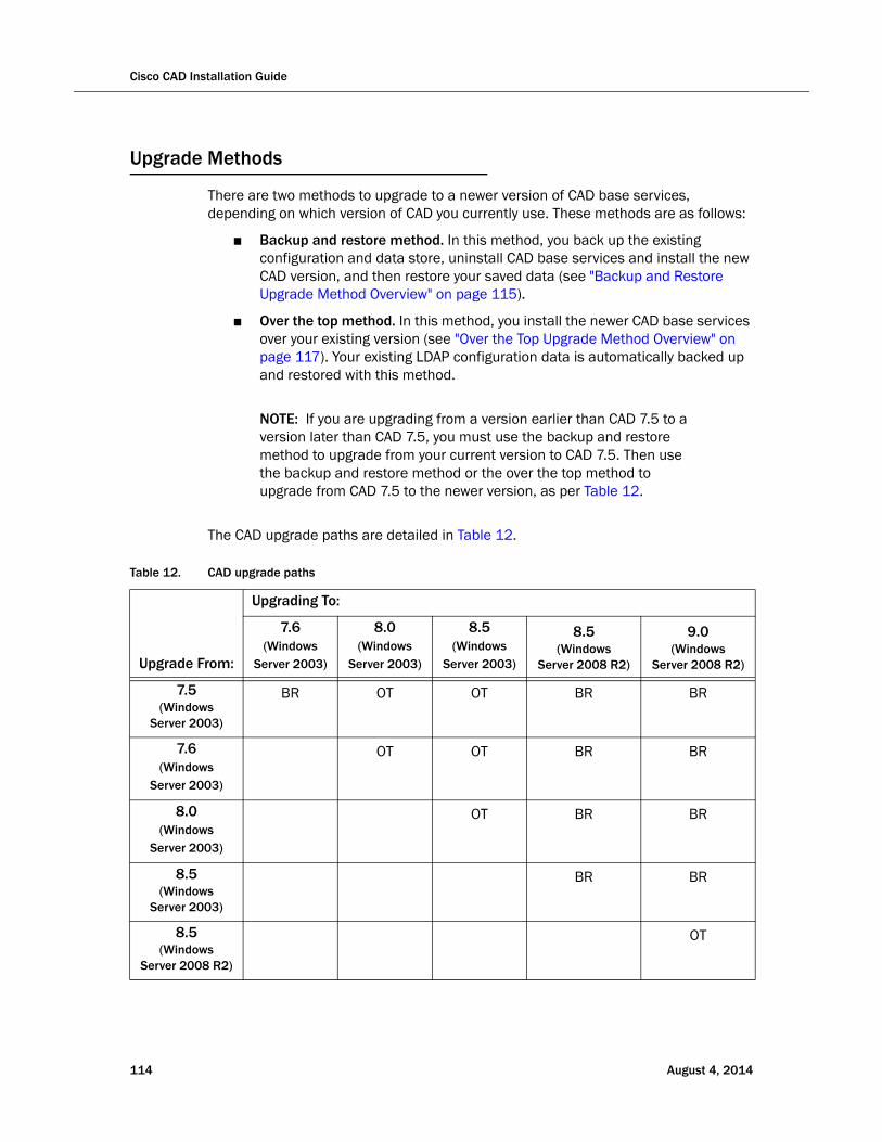
Cisco CAD Installation Guide
Upgrade Methods
There are two methods to upgrade to a newer version of CAD base services, depending on which version of CAD you currently use. These methods are as follows:
■ Backup and restore method. In this method, you back up the existing configuration and data store, uninstall CAD base services and install the new CAD version, and then restore your saved data (see "Backup and Restore Upgrade Method Overview" on page 115).
■ Over the top method. In this method, you install the newer CAD base services over your existing version (see "Over the Top Upgrade Method Overview" on page 117). Your existing LDAP configuration data is automatically backed up and restored with this method.
NOTE: If you are upgrading from a version earlier than CAD 7.5 to a version later than CAD 7.5, you must use the backup and restore method to upgrade from your current version to CAD 7.5. Then use the backup and restore method or the over the top method to upgrade from CAD 7.5 to the newer version, as per Table 12.
The CAD upgrade paths are detailed in Table 12.
Table 12. CAD upgrade paths
Upgrade From:
Upgrading To:
7.6(Windows
Server 2003)
8.0(Windows
Server 2003)
8.5(Windows
Server 2003)
8.5(Windows
Server 2008 R2)
9.0(Windows
Server 2008 R2)
7.5(Windows
Server 2003)
BR OT OT BR BR
7.6(Windows
Server 2003)
OT OT BR BR
8.0(Windows
Server 2003)
OT BR BR
8.5 (Windows
Server 2003)
BR BR
8.5 (Windows
Server 2008 R2)
OT
114 August 4, 2014

Upgrade Methods
NOTE: Prior implementations of CAD 8.0, 8.5, and 9.0 supported the use of flat files or Microsoft SQL Server as the data store. As a matter of policy, effective immediately with release 9.0(3), all customers with new deployments of any version of Cisco Agent Desktop must use SQL Server as the data store, and not flat files. The rationale behind this policy is that deployments with a fully replicated SQL Server database experience a more complete feature set and better performance and stability.
Customers who are upgrading to CAD 9.0(3) from a previous version of CAD that was run on Windows Server 2003 (CAD 7.5, 7.6, 8.0, 8.5(1), and 8.5(2a)) must migrate to SQL Server 2008 R2 as the data store.
Customers who used flat files with CAD 8.5(4) and CAD 9.0(1a) running on Windows Server 2008 R2 can continue to use flat files when upgrading to CAD 9.0(3), but are also encouraged to migrate to SQL Server 2008 R2. CAD documentation outlines the caveats associated with the use of flat files, including loss of functionality during fail over situations that might be cause by several reasons, network issues being the most common. Cisco Support and TAC reserves the right to request a migration to SQL Server 2008 R2 as a resolution plan.
Backup and Restore Upgrade Method Overview
The backup and restore utilities used in the following upgrade procedure are described in detail in "Backup and Restore" on page 126.
NOTE: You must use the utilities from the version you are backing up. For example, if you are upgrading from CAD 7.1 to CAD 9.0, use the CAD 7.1 utilities to back up your data. Then use the CAD 9.0 utilities to restore your data once you have completed the upgrade.
KEY: BR = backup and restore methodOT = over the top method
Table 12. CAD upgrade paths (cont’d)
Upgrade From:
Upgrading To:
7.6(Windows
Server 2003)
8.0(Windows
Server 2003)
8.5(Windows
Server 2003)
8.5(Windows
Server 2008 R2)
9.0(Windows
Server 2008 R2)
August 4, 2014 115

Cisco CAD Installation Guide
To upgrade using the backup and restore method:
1. On the computer that hosts the CAD base services, open a command window and navigate to C:\Program Files\Cisco\Desktop\bin (the default location for CAD utilities).
2. At the prompt, run the following command to back up your current LDAP configuration data:
CDBRTool /B /L “<configuration data backup folder path>”
3. At the prompt, run the following command to back up your audio recordings:
CDBRTool /B /A “<recordings backup folder path>”
4. Back up your Recording and Statistics database using BackupDB (see "BackupDB Utility" on page 128).
NOTE: Save the three types of backup files to different folders. Keeping the backup files separated prevents the backup and restore tools from reading from or writing to the wrong type of file. The backup folders must be on a local drive to avoid file permission issues that can arise if they are saved to a network drive. The backups can be copied to a network drive later on for safekeeping.
NOTE: Keep your backups in case you need to roll back to your previous version of CAD.
5. Uninstall your current version of CAD.
6. Install the newer version of CAD.
NOTE: If you are upgrading to a replicated system, start with installing CAD 9.0 on the server that you want to designate as the primary node.
After the installation finishes, the CAD Configuration Setup utility starts automatically.
7. In the CAD Configuration Setup utility, complete the nodes.
■ If you are installing CAD 9.0, refer to "CAD Configuration Setup Utility" on page 60 for information.
■ If you backed up data from a previous version of CAD, restore your data by completing the Recording and Statistics Database node (see page 75) and Restore Backup Data node (see page 80) with the location of your backup files.
8. Click Save and then exit the CAD Configuration Setup utility.
116 August 4, 2014
Upgrade Methods
■ If you are upgrading to a non-replicated system, you have completed the upgrade.
■ If you are upgrading to a replicated system, complete the remaining steps on the secondary server.
9. Log onto the secondary server.
10. Uninstall the current version of CAD.
11. Install the newer version of CAD. After the installation finishes, the CAD Configuration Setup utility starts automatically.
12. In the CAD Configuration Setup utility, complete the data entry windows as described in "Configuring a Secondary Server in a Replicated System" on page 91. The fields for each node are already populated based on the information entered with the CAD Configuration Setup utility on the primary server (Side A). Navigate through each node and verify the information is correct.
When you have finished, save and then exit the CAD Configuration Setup utility.
The upgrade on both servers is now done and replication has been re-established.
Over the Top Upgrade Method Overview
When using the over the top upgrade method, the installation process automatically backs up your CAD services’ LDAP configuration data. It is a good idea, however, to manually back up your data as well (see "CDBRTool Utility" on page 131 and "BackupDB Utility" on page 128).
NOTE: Keep your backups in case you need to roll back to your previous version of CAD.
You must shut down replication before you begin the upgrade process.
To upgrade using the over the top method:
1. Install the newer version of CAD over the older version.
NOTE: If you are upgrading to a replicated system, start with installing CAD 9.0 on the server that you want to designate as the primary server.
After the installation finishes, the CAD Configuration Setup utility starts automatically.
August 4, 2014 117

Cisco CAD Installation Guide
2. The CAD Configuration Setup utility starts automatically. The fields are automatically populated based on the settings you configured in your previous version of CAD. Verify this information is correct.
■ If you use SQL Server, make sure that you select SQL Server in the Recording and Statistics Service Database Configuration node.
■ Select Blank Database on the Recording and Statistics Database node.
■ On the Restore Backup Data node, select No.
Your data will be automatically restored.
3. Exit the CAD Configuration Setup utility.
■ If you are upgrading to a single server, you have completed the upgrade.
■ If you are upgrading to a replicated system, complete the remaining steps on the secondary server.
4. Log onto the secondary server.
5. Install the newer version of CAD over the older version. After the installation finishes, the CAD Configuration Setup utility starts automatically.
6. The CAD Configuration Setup utility starts automatically. The fields are automatically populated based on the settings you configured in your previous version of CAD. Verify this information is correct.
7. Exit the CAD Configuration Setup utility.
8. Restart both servers.
118 August 4, 2014
Upgrading from CAD 7.5/7.6, CAD 8.0, and CAD 8.5 (Windows Server 2003)
Upgrading from CAD 7.5/7.6, CAD 8.0, and CAD 8.5 (Windows Server 2003)
Going from Flat Files to SQL Server 2008 R2
1. Backup the data for your current CAD installation. See "Backing Up CAD Data" on page 126 for more information.
NOTE: Save the three types of backup files to different folders. Keeping the backup files separated prevents the backup and restore tools from reading from or writing to the wrong type of file.
NOTE: Keep your backups in case you need to roll back to your previous version of CAD.
2. Upgrade the server (Side A and Side B in a redundant environment) from Windows Server 2003 to Windows Server 2008 R2. See your Microsoft documentation for information on how to do this.
NOTE: Your current version of CAD will be uninstalled in the process of upgrading your Windows servers.
3. Complete the preinstallation preparation. See "Preparing User Accounts and Permissions" on page 40 for more information.
4. Install and configure SQL Server 2008 R2 (on Side A and Side B in a redundant system). See "Configuring Microsoft SQL Server 2008 R2 for CAD 9.0" on page 41 for detailed steps.
5. Install CAD services on the primary server (Side A) where SQL Server 2008 R2 is installed. Refer to "Installing CAD Base Services" on page 56 for detailed steps.
6. Configure CAD services on Side A with the CAD Configuration Setup utility. Refer to "Configuring a Primary Server in a Replicated System" on page 62 for steps to configure CAD services on the primary server (Side A). For more information about the CAD Configuration Setup utility refer to "CAD Configuration Setup Utility" on page 60.
The nodes will appear in the following order:
a. Unified CM SOAP AXL Access (page 64)
b. Unified Communications Manager (page 66)
c. CTI Server (Unified CM) (page 68)
d. CTI OS (page 70)
August 4, 2014 119
Cisco CAD Installation Guide
e. ICM Admin Workstation Distributor (page 71)
f. ICM Admin Workstation Database (page 73)
g. Recording and Statistics Database Configuration (page 75)
h. Recording and Statistics Service Database (page 78)
i. Restore Backup Data (page 80)
7. License CAD with Unified CCE License Administration. Refer to "Licensing CAD 9.0" on page 94 for more information.
8. Install CAD services on the secondary server (Side B). The steps are the same as they were on Side A. Refer to "Installing CAD Base Services" on page 56 for more information.
9. Configure CAD on Side B with the CAD Configuration Setup utility. Refer to "Configuring a Secondary Server in a Replicated System" on page 91 for more information. The fields will already be completed based on the information you entered while configuring CAD on Side A. Verify this information is correct.
NOTE: You do not have to complete Unified CCE License Administration on Side B.
10. Restore your backed up data to CAD 9.0. See "Restoring CAD Data" on page 127 for more information.
NOTE: In a redundant system, restore data only on Side A. The restored data will be replicated on Side B the next time the two sides are synchronized.
11. Restart both servers.
12. Using the CAD Configuration Setup utility, modify your settings to prepare for switching data stores. Refer to "Preparing for Switching Data Stores" on page 139 for detailed steps.
13. Switch your data store from flat files to SQL Server using the Data Migration Tool. Refer to "Using the Data Migration Tool" on page 140 for detailed steps.
14. If you also upgraded your Unified ICM verify the registry on the peripheral gateway (PG) computer. Refer to "Modifying the Peripheral Gateway Registry" on page 97 for more information.
Going from MSDE or SQL Server 2005 to SQL Server 2008 R2
1. Backup the data for your current CAD installation. See "Backing Up CAD Data" on page 126 for more information.
120 August 4, 2014
Upgrading from CAD 7.5/7.6, CAD 8.0, and CAD 8.5 (Windows Server 2003)
NOTE: Save the three types of backup files to different folders. Keeping the backup files separated prevents the backup and restore tools from reading from or writing to the wrong type of file.
NOTE: Keep your backups in case you need to roll back to your previous version of CAD.
2. Upgrade the server (Side A and Side B in a redundant environment) from Windows Server 2003 to Windows Server 2008 R2. See your Microsoft documentation for information on how to do this.
NOTE: Your current version of CAD will be uninstalled in the process of upgrading your Windows servers.
3. Complete the preinstallation preparation. See "Preparing User Accounts and Permissions" on page 40 for more information.
4. Install and configure SQL Server 2008 R2 (on Side A and Side B in a redundant system). See "Configuring Microsoft SQL Server 2008 R2 for CAD 9.0" on page 41 for detailed steps.
5. Install CAD services on the primary server (Side A) where SQL Server 2008 R2 is installed. Refer to "Installing CAD Base Services" on page 56 for detailed steps.
6. Configure CAD services on Side A with the CAD Configuration Setup utility. Refer to "Configuring a Primary Server in a Replicated System" on page 62 for steps to configure CAD services on the primary server (Side A). For more information about the CAD Configuration Setup utility refer to "CAD Configuration Setup Utility" on page 60.
The nodes will appear in the following order:
a. Unified CM SOAP AXL Access (page 64)
b. Unified Communications Manager (page 66)
c. CTI Server (Unified CM) (page 68)
d. CTI OS (page 70)
e. ICM Admin Workstation Distributor (page 71)
f. ICM Admin Workstation Database (page 73)
g. Recording and Statistics Database Configuration (page 75)
h. Recording and Statistics Service Database (page 78)
i. Restore Backup Data (page 80)
7. License CAD with Unified CCE License Administration. Refer to "Licensing CAD 9.0" on page 94 for more information.
August 4, 2014 121

Cisco CAD Installation Guide
8. Install CAD services on the secondary server (Side B). The steps are the same as they were on Side A. Refer to "Installing CAD Base Services" on page 56 for more information.
9. Configure CAD on Side B with the CAD Configuration Setup utility. Refer to "Configuring a Secondary Server in a Replicated System" on page 91 for more information. The fields will already be completed based on the information you entered while configuring CAD on Side A. Verify this information is correct.
NOTE: You do not have to complete Unified CCE License Administration on Side B.
10. Restart both servers.
11. If you also upgraded your Unified ICM verify the registry on the peripheral gateway (PG) computer. Refer to "Modifying the Peripheral Gateway Registry" on page 97 for more information.
122 August 4, 2014
Upgrading from 8.5 (Windows Server 2008 R2)
Upgrading from 8.5 (Windows Server 2008 R2)
Going from Flat Files to Flat Files
You can install CAD 9.0 using the over the top method. Refer to "Over the Top Upgrade Method Overview" on page 117 for more information.
1. Complete the preinstallation preparation. See "Preparing User Accounts and Permissions" on page 40 for more information.
2. You must shut down replication before you begin the upgrade process. Refer to "Shutting Down Replication" on page 158 for detailed steps.
3. Install CAD 9.0 base services over the older version on the primary server (Side A). Refer to "Installing CAD Base Services" on page 56.
4. The CAD Configuration Setup utility starts automatically. The fields are automatically populated based on the settings you configured in CAD 8.5. Verify this information is correct.
5. License CAD with Unified CCE License Administration. The fields are automatically populated based on the licensing information you entered during the installation of your old version of CAD. Verify the license type and number of seats. Click Cancel. Refer to "Licensing CAD 9.0" on page 94 for more information.
6. Install CAD base services on the secondary server (Side B). The steps are the same as they were on Side A. Refer to "Installing CAD Base Services" on page 56 for more information.
7. The CAD Configuration Setup utility starts automatically. The fields are automatically populated based on the settings you configured in CAD 8.5. Verify this information is correct.
NOTE: You do not have to complete Unified CCE License Administration on Side B.
8. Restart both servers.
9. If you also upgraded your Unified ICM verify the registry on the peripheral gateway (PG) computer. Refer to "Modifying the Peripheral Gateway Registry" on page 97 for more information.
Going from Flat Files to SQL Server 2008 R2
1. Complete the preinstallation preparation. See "Preparing User Accounts and Permissions" on page 40 for more information.
August 4, 2014 123
Cisco CAD Installation Guide
2. You must shut down replication before you begin the upgrade process. Refer to "Shutting Down Replication" on page 158 for detailed steps.
3. Install and configure SQL Server 2008 R2 (on Side A and Side B in a redundant system). See "Configuring Microsoft SQL Server 2008 R2 for CAD 9.0" on page 41 for detailed steps.
4. Install CAD 9.0 base services over the top of the older version on the primary server (Side A) where SQL Server 2008 R2 is installed. Refer to "Installing CAD Base Services" on page 56 for detailed steps.
5. The CAD Configuration Setup utility starts automatically. The fields are automatically populated based on the settings you configured in CAD 8.5. Verify this information is correct.
■ On the Recording and Statistic Database node, select Blank Database.
■ On the Restore Backup Data node, select No.
Your data will be automatically restored.
6. License CAD with Unified CCE License Administration. The fields are automatically populated based on the licensing information you entered during the installation of your old version of CAD. Verify the license type and number of seats. Click Cancel. Refer to "Licensing CAD 9.0" on page 94 for more information.
7. Install CAD base services on the secondary server (Side B). The steps are the same as they were on Side A. Refer to "Installing CAD Base Services" on page 56 for more information.
8. The CAD Configuration Setup utility starts automatically. The fields are automatically populated based on the settings you configured in CAD 8.5. Verify this information is correct.
NOTE: You do not have to complete Unified CCE License Administration on Side B.
9. Restart both servers.
10. Using the CAD Configuration Setup utility, modify your settings to prepare for switching data stores. Refer to "Preparing for Switching Data Stores" on page 139 for detailed steps.
11. Switch your data store from flat files to SQL Server using the Data Migration Tool. Refer to "Using the Data Migration Tool" on page 140 for detailed steps.
12. If you also upgraded your Unified ICM verify the registry on the peripheral gateway (PG) computer. Refer to "Modifying the Peripheral Gateway Registry" on page 97 for more information.
124 August 4, 2014
Upgrading from 8.5 (Windows Server 2008 R2)
Going from SQL Server 2005 to SQL Server 2008 R2
You can install CAD 9.0 using the over the top method. Refer to "Over the Top Upgrade Method Overview" on page 117 for more information.
1. Complete the preinstallation preparation. See "Preparing User Accounts and Permissions" on page 40 for more information.
2. You must shut down replication before you begin the upgrade process. Refer to "Shutting Down Replication" on page 158 for detailed steps.
3. Upgrade from SQL Server 2005 to SQL Server 2008 R2 (on Side A and Side B in a redundant system). See "Upgrading from SQL Server 2005" on page 52 for detailed steps.
4. Install CAD 9.0 base services over the older version on the primary server (Side A). Refer to "Installing CAD Base Services" on page 56.
5. The CAD Configuration Setup utility starts automatically. The fields are automatically populated based on the settings you configured in CAD 8.5. Verify this information is correct.
6. License CAD with Unified CCE License Administration. The fields are automatically populated based on the licensing information you entered during the installation of your old version of CAD. Verify the license type and number of seats. Click Cancel. Refer to "Licensing CAD 9.0" on page 94 for more information.
7. Install CAD base services on the secondary server (Side B). The steps are the same as they were on Side A. Refer to "Installing CAD Base Services" on page 56 for more information.
8. The CAD Configuration Setup utility starts automatically. The fields are automatically populated based on the settings you configured in CAD 8.5. Verify this information is correct.
9. Restart both servers.
10. Restart replication. Refer to "Restarting Replication" on page 159 for detailed steps.
11. If you also upgraded your Unified ICM verify the registry on the peripheral gateway (PG) computer. Refer to "Modifying the Peripheral Gateway Registry" on page 97 for more information.
August 4, 2014 125
Cisco CAD Installation Guide
Backup and Restore
This section describes how to back up and restore CAD configuration settings and recordings using the CAD backup and restore utilities. For the most up-to-date information on Back and Restore procedures and utilities, see the Release Notes.
NOTE: Save each type of backup file to a different folder. Keeping the backup files separated prevents the backup and restore tools from reading from or writing to the wrong type of file.
NOTE: You must use the utilities that were provided with the version of CAD you are backing up and with the version of CAD to which you are restoring the data. For example, if you are upgrading from CAD 7.5 to CAD 9.0, you must use the CAD 7.5 utilities to back up data, and the CAD 9.0 utilities to restore data.
Backup File Location
The Backup and Restore tools enable you to save backup files to either network or local drives. However, due to file permission issues, the CAD Configuration Setup utility cannot restore files if the backups are located on a network drive.
For this reason it is recommended that you save backup files to a local drive, and then copy those backups to a secure location elsewhere if desired.
NOTE: Save each type of backup file to a different folder. Keeping the backup files separated prevents the backup and restore tools from reading from or writing to the wrong type of file.
Backing Up CAD Data
Backups are recommended to protect your CAD 9.0 configuration settings and recordings. Use the following procedures for backing up your system. Best practice is to perform backups during down times when all agents are logged out.
In a High Availability system, run the CDBRTool utility on both Side A and Side B to back up audio recordings that are saved on both sides. However, run the BackupDB tool only on one side, not on both sides.
To back up CAD data:
1. On the server hosting the CAD base services, run CDBRTool to back up the configuration data and/or recordings (see "CDBRTool Utility" on page 131).
2. On the server hosting the Recording and Statistics service, run the BackupDB utility to back up recording metadata (see "BackupDB Utility" on page 128).
126 August 4, 2014
Backup and Restore
NOTE: To prevent potential file permission issues upon restore, save Recording and Statistics service database backup files to a local drive. If desired, copy the backup files to a secure location elsewhere.
Restoring CAD Data
The process for restoring your CAD configuration data and recordings is outlined here. After you have upgraded or reinstalled the CAD services, the CAD Configuration Setup utility runs. Part of the CAD Configuration Setup utility is restoring backed-up data.
To restore CAD data if you are upgrading to CAD 9.0 or reinstalling CAD 9.0:
1. In the Recording and Statistics Service Database node of the CAD Configuration Setup utility, select Restore recording metadata (BackupDB) and enter:
■ The path where the recording metadata backup file created by the BackupDB utility is saved
■ The path where the backup audio files created by the CDBRTool utility are saved
NOTE: You can restore from a flat file system to a flat file system or from a SQL system to a SQL system. You can also convert flat files into a SQL system. See "Switching Data Stores" on page 139 for more information.
This restores the recording metadata and recordings. See "Recording and Statistics Service Database" on page 78 for more information.
2. In the Restore Backup Data window, answer Yes and enter the path where the backup files created by the CDBRTool utility are saved.
This restores the CAD services LDAP (Directory Services) database. (See "Restore Backup Data" on page 80 for more information.)
NOTE: In a redundant system, restore data only on Side A. The restored data will be replicated on Side B the next time the two sides are synchronized.
August 4, 2014 127
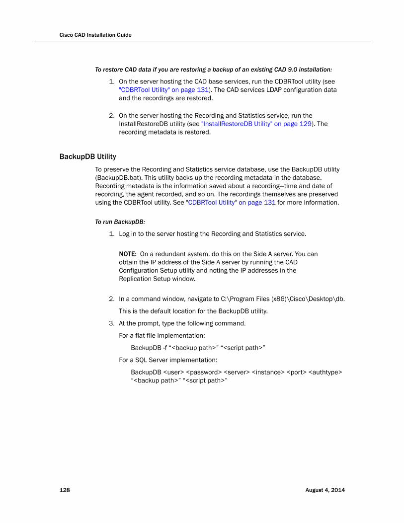
Cisco CAD Installation Guide
To restore CAD data if you are restoring a backup of an existing CAD 9.0 installation:
1. On the server hosting the CAD base services, run the CDBRTool utility (see "CDBRTool Utility" on page 131). The CAD services LDAP configuration data and the recordings are restored.
2. On the server hosting the Recording and Statistics service, run the InstallRestoreDB utility (see "InstallRestoreDB Utility" on page 129). The recording metadata is restored.
BackupDB Utility
To preserve the Recording and Statistics service database, use the BackupDB utility (BackupDB.bat). This utility backs up the recording metadata in the database. Recording metadata is the information saved about a recording—time and date of recording, the agent recorded, and so on. The recordings themselves are preserved using the CDBRTool utility. See "CDBRTool Utility" on page 131 for more information.
To run BackupDB:
1. Log in to the server hosting the Recording and Statistics service.
NOTE: On a redundant system, do this on the Side A server. You can obtain the IP address of the Side A server by running the CAD Configuration Setup utility and noting the IP addresses in the Replication Setup window.
2. In a command window, navigate to C:\Program Files (x86)\Cisco\Desktop\db.
This is the default location for the BackupDB utility.
3. At the prompt, type the following command.
For a flat file implementation:
BackupDB -f “<backup path>” “<script path>”
For a SQL Server implementation:
BackupDB <user> <password> <server> <instance> <port> <authtype> “<backup path>” “<script path>”
128 August 4, 2014
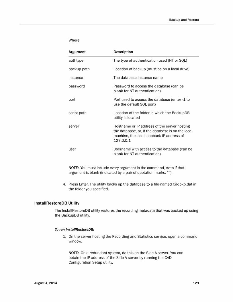
Backup and Restore
Where
Argument Description
authtype The type of authentication used (NT or SQL)
backup path Location of backup (must be on a local drive)
instance The database instance name
password Password to access the database (can be blank for NT authentication)
port Port used to access the database (enter -1 to use the default SQL port)
script path Location of the folder in which the BackupDB utility is located
server Hostname or IP address of the server hosting the database, or, if the database is on the local machine, the local loopback IP address of 127.0.0.1
user Username with access to the database (can be blank for NT authentication)
NOTE: You must include every argument in the command, even if that argument is blank (indicated by a pair of quotation marks: ““).
4. Press Enter. The utility backs up the database to a file named Cadbkp.dat in the folder you specified.
InstallRestoreDB Utility
The InstallRestoreDB utility restores the recording metadata that was backed up using the BackupDB utility.
To run InstallRestoreDB:
1. On the server hosting the Recording and Statistics service, open a command window.
NOTE: On a redundant system, do this on the Side A server. You can obtain the IP address of the Side A server by running the CAD Configuration Setup utility.
August 4, 2014 129

Cisco CAD Installation Guide
2. Navigate to the folder where InstallRestoreDB.bat is located. The default location is C:\Program Files (x86)\Cisco\Desktop\DB.
3. At the prompt, type the following command.
For a flat file implementation:
InstallRestoreDB -f “<backup path>” “<script path>”
For a SQL Server implementation:
InstallRestoreDB <user> <password> <server> <instance> <port> <authtype> “<backup path>” “<script path>”
Where
Argument Description
authtype The type of authentication used (SQL or NT)
backup path Location of backup (must be on a local drive)
instance The database instance name
password Password to access the database (can be blank for NT authentication)
port Port used to access the database (enter -1 to use the default SQL port)
script path Location of the folder in which the BackupDB utility is located
server Hostname or IP address of the server hosting the database, or, if the database is on the local machine, the local loopback IP address of 127.0.0.1
user Username with access to the database (can be blank for NT authentication)
NOTE: You must include every argument in the command, even if that argument is blank (indicated by a pair of quotation marks: “”).
4. Press Enter. The recording metadata is restored to the specified database.
130 August 4, 2014
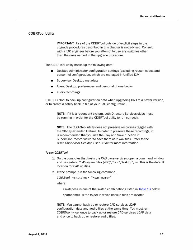
Backup and Restore
CDBRTool Utility
IMPORTANT: Use of the CDBRTool outside of explicit steps in the upgrade procedures described in this chapter is not advised. Consult with a TAC engineer before you attempt to use any switches other than the ones named in the upgrade procedure.
The CDBRTool utility backs up the following data:
■ Desktop Administrator configuration settings (excluding reason codes and personnel configuration, which are managed in Unified ICM)
■ Supervisor Desktop metadata
■ Agent Desktop preferences and personal phone books
■ audio recordings
Use CDBRTool to back up configuration data when upgrading CAD to a newer version, or to create a safety backup file of your CAD configuration.
NOTE: If it is a redundant system, both Directory Services sides must be running in order for the CDBRTool utility to run correctly.
NOTE: The CDBRTool utility does not preserve recordings tagged with the 30-day extended lifetime. In order to preserve these recordings, it is recommended that you use the Play and Save function in Supervisor Record Viewer to save them as *.wav files. Refer to the Cisco Supervisor Desktop User Guide for more information.
To run CDBRTool:
1. On the computer that hosts the CAD base services, open a command window and navigate to C:\Program Files (x86)\Cisco\Desktop\bin. This is the default location for CAD utilities.
2. At the prompt, run the following command.
CDBRTool <switches> “<pathname>”
where:
<switches> is one of the switch combinations listed in Table 13 below
<pathname> is the folder in which backup files are located
NOTE: You cannot back up or restore CAD services LDAP configuration data and audio files at the same time. You must run CDBRTool twice, once to back up or restore CAD services LDAP data and once to back up or restore audio files.
August 4, 2014 131
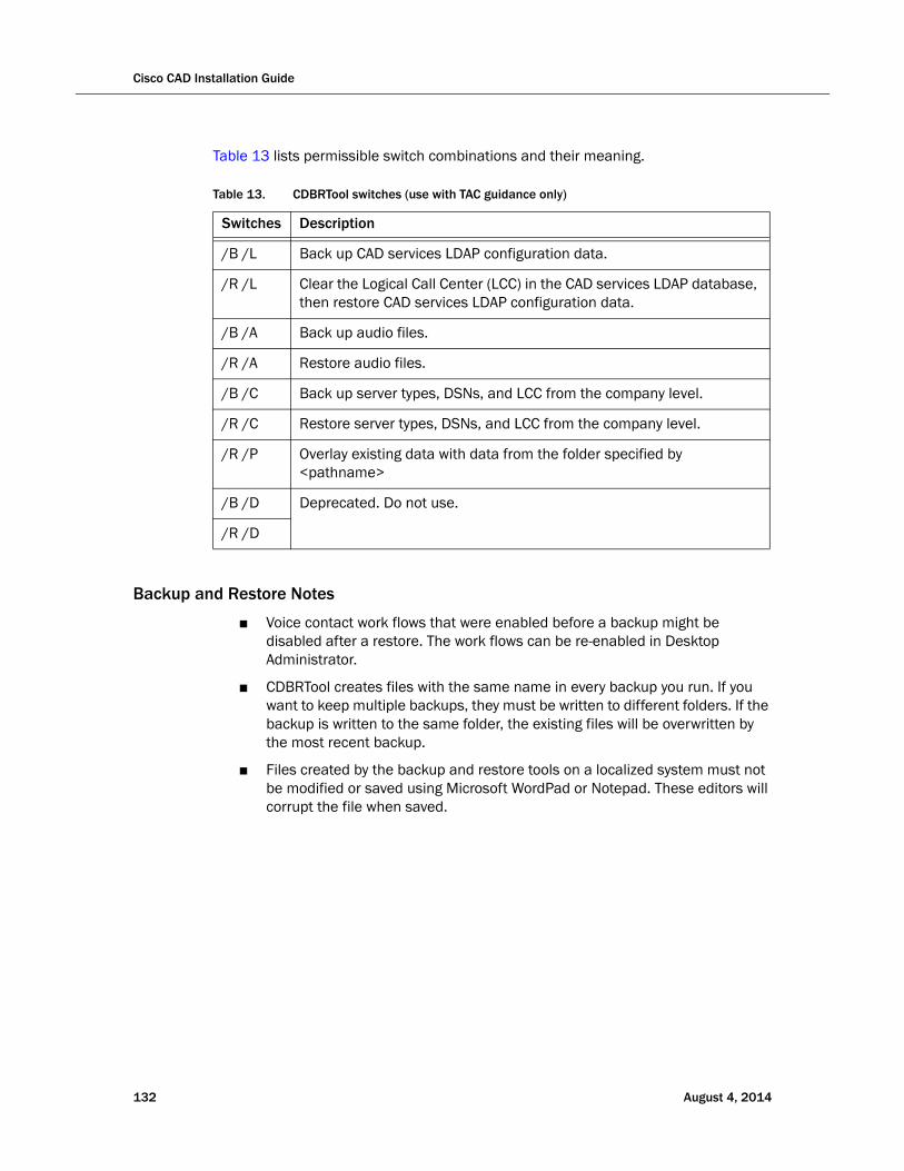
Cisco CAD Installation Guide
Table 13 lists permissible switch combinations and their meaning.
Backup and Restore Notes
■ Voice contact work flows that were enabled before a backup might be disabled after a restore. The work flows can be re-enabled in Desktop Administrator.
■ CDBRTool creates files with the same name in every backup you run. If you want to keep multiple backups, they must be written to different folders. If the backup is written to the same folder, the existing files will be overwritten by the most recent backup.
■ Files created by the backup and restore tools on a localized system must not be modified or saved using Microsoft WordPad or Notepad. These editors will corrupt the file when saved.
Table 13. CDBRTool switches (use with TAC guidance only)
Switches Description
/B /L Back up CAD services LDAP configuration data.
/R /L Clear the Logical Call Center (LCC) in the CAD services LDAP database, then restore CAD services LDAP configuration data.
/B /A Back up audio files.
/R /A Restore audio files.
/B /C Back up server types, DSNs, and LCC from the company level.
/R /C Restore server types, DSNs, and LCC from the company level.
/R /P Overlay existing data with data from the folder specified by <pathname>
/B /D Deprecated. Do not use.
/R /D
132 August 4, 2014

Rolling Back CAD 9.0 to an Earlier Version of CAD
Rolling Back CAD 9.0 to an Earlier Version of CAD
To use the following procedure, you must have backed up your original version of CAD before installing CAD 9.0.
To uninstall CAD 9.0 and revert to an earlier version of CAD:
1. If you are rolling back CAD 9.0 on a replicated system, shut down replication now (see "Shutting Down and Restarting Replication" on page 157).
NOTE: If you do not shut down replication before completing this procedure, your CAD services LDAP database will become corrupted.
2. Uninstall CAD 9.0.
3. Install your previous CAD version according to the product documentation.
4. Restore your backed-up data using the CAD Configuration Setup utility:
■ The configuration data backed up with CDBRTool or DBBackupTool is restored by entering the location of the backup file in the Restore Backup Data node.
■ The Recording and Statistics database backed up with BackupDB is restored by selecting “Restore From” and entering the location of the backup file in the Recording and Statistics Service Database node.
5. If you are rolling back a replicated system, re-establish replication (see "Shutting Down and Restarting Replication" on page 157).
Rollback Notes
■ Automated software rollback from CAD 9.0 to a previous version is not supported.
■ If CAD 9.0 is rolled back to a version prior to 8.0, the service releases that apply to the earlier version must be reinstalled. For example, if you are rolling back from CAD 9.0 to 7.6, any desired CAD 7.6 service releases must be reinstalled.
■ If CAD 9.0 is rolled back to CAD 8.0, the CAD 8.0 Maintenance Releases must be reinstalled.
August 4, 2014 133

Cisco CAD Installation Guide
Changing Feature Levels in an Upgrade
If you are changing feature levels (for instance, changing from CAD Standard to CAD Premium), you must run Unified CCE License Administration (LicenseAdmin.exe) after the upgrade is completed and then restart the BIPPA service.
NOTE: Licensing your software can only be completed by a Cisco channel partner or Cisco Professional Services.
As a best practice, after you change feature level, back up your system at the new feature level. Then, delete any backups you made before changing the feature level.
For information on the features provided at each feature level, see "CAD 9.0 Feature Levels" on page 13.
To change feature levels in an upgrade:
1. On the computer that hosts the CAD services, navigate to the folder C:\Program Files (x86)\Cisco\Desktop\bin.
2. Run LicenseAdmin.exe to start Unified CCE License Administration.
3. In the Unified CCE License Administration window, click License URL. Your web browser starts and opens the secured licensing website at http://209.46.83.138/sws/ciscoLicense/LicenseRegister.html.
4. In the Customer ID field, enter 0 (zero), then click Continue.
NOTE: You must enter 0 in the customer ID field, even if you already have a customer ID number.
5. Enter the product information. This includes the new package (feature level) you have purchased.
6. Continue through the licensing process (see "Licensing CAD 9.0" on page 94).
7. When licensing is completed, restart the BIPPA service.
134 August 4, 2014

Installing a Maintenance Release or Engineering Special
Installing a Maintenance Release or Engineering Special
Updates are released periodically. There are several update types, which are described below.
Engineering Test (ET)
An ET is an installable component that contains the files needed to assist developers when diagnosing a problem. An ET is intended for a limited scope test. An ET can contain server and/or client files. Apply the ET on the servers or client desktops that you want to test. If the ET also contains client files, install the ET directly on the client desktop. The ET does not work with automated updates.
Engineering Special (ES)
An ES is an installable component that addresses a specific bug fix needed by one or more customers. An ES is cumulative. If two ESes are issued against a base release, the latest ES contains all the fixes provided in the previous ES. An ES can contain server and/or client fixes. Always install an ES on the same server as the CAD base services for automatic updates to work. An ES is tied to a specific version of the base release and/or Maintenance Release (MR). If the ES contains no fixes for the desktop clients, automated updates do not run.
Maintenance Release (MR)
An MR contains all patches for all bugs found and fixed since the base release of the product. An MR is cumulative. If two MRs are issued against a base release, the latest MR contains all the fixes provided in the previous MR. For example, 9.0(3) contains all the fixes provided in 9.0(1a).
An MR contains fixes for the CAD base services server and/or client desktops. Always install the MR on the same server as the CAD base services. CAD uses automated updates (if enabled) to update desktop clients when you install the MR. If the MR contains no fixes for the desktop clients, automated updates do not run.
Each MR appears in the Add/Remove Programs window. Uninstalling an MR allows for rollback to a previous state. If an MR is server side only, the Add/Remove Program title displays Server only.
MR, ES, and ET Guidelines
Use the following guidelines when installing or uninstalling an MR, ES, or ET.
■ Uninstall any ETs before you install another ET or an MR or ES.
August 4, 2014 135
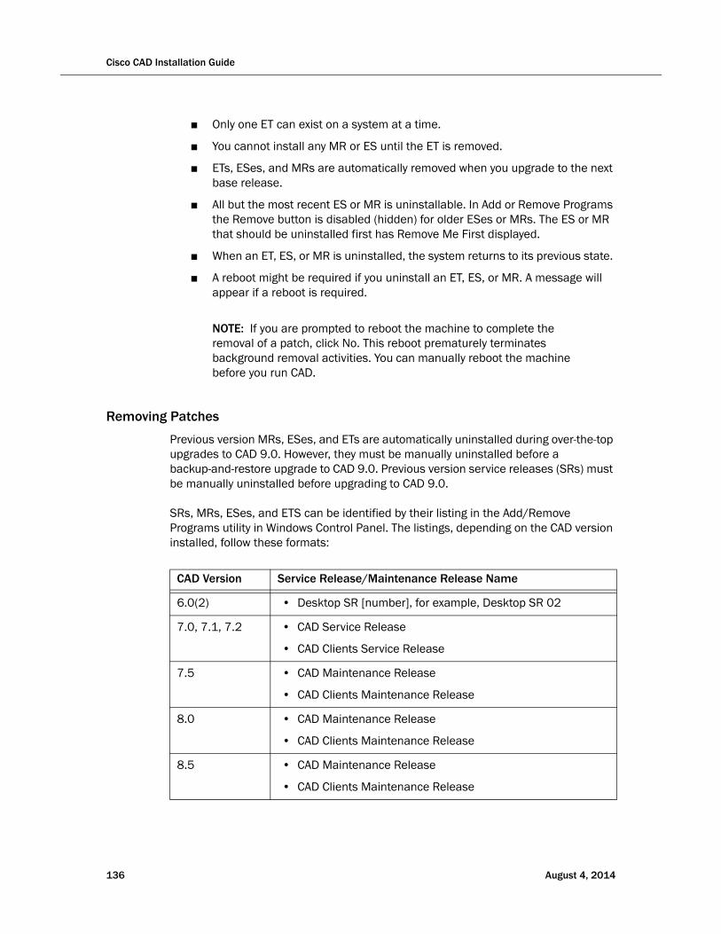
Cisco CAD Installation Guide
■ Only one ET can exist on a system at a time.
■ You cannot install any MR or ES until the ET is removed.
■ ETs, ESes, and MRs are automatically removed when you upgrade to the next base release.
■ All but the most recent ES or MR is uninstallable. In Add or Remove Programs the Remove button is disabled (hidden) for older ESes or MRs. The ES or MR that should be uninstalled first has Remove Me First displayed.
■ When an ET, ES, or MR is uninstalled, the system returns to its previous state.
■ A reboot might be required if you uninstall an ET, ES, or MR. A message will appear if a reboot is required.
NOTE: If you are prompted to reboot the machine to complete the removal of a patch, click No. This reboot prematurely terminates background removal activities. You can manually reboot the machine before you run CAD.
Removing Patches
Previous version MRs, ESes, and ETs are automatically uninstalled during over-the-top upgrades to CAD 9.0. However, they must be manually uninstalled before a backup-and-restore upgrade to CAD 9.0. Previous version service releases (SRs) must be manually uninstalled before upgrading to CAD 9.0.
SRs, MRs, ESes, and ETS can be identified by their listing in the Add/Remove Programs utility in Windows Control Panel. The listings, depending on the CAD version installed, follow these formats:
CAD Version Service Release/Maintenance Release Name
6.0(2) • Desktop SR [number], for example, Desktop SR 02
7.0, 7.1, 7.2 • CAD Service Release
• CAD Clients Service Release
7.5 • CAD Maintenance Release
• CAD Clients Maintenance Release
8.0 • CAD Maintenance Release
• CAD Clients Maintenance Release
8.5 • CAD Maintenance Release
• CAD Clients Maintenance Release
136 August 4, 2014

Installing a Maintenance Release or Engineering Special
Upgrading to 9.0(3)
If you are upgrading to CAD 9.0(3) from a version of CAD prior to 9.0, you must upgrade to 9.0(1a) using the appropriate method listed in Table 12 on page 114. Then you can install 9.0(3).
August 4, 2014 137
Cisco CAD Installation Guide
Upgrading CAD Desktop Clients
If automated updates are enabled (see "Services Configuration" on page 84), CAD desktop clients are upgraded automatically the next time the client application is started and it detects a newer version of the CAD services. For other methods of upgrading CAD desktop clients, see "Configuring CAD Client MSI Files" on page 99 and "Using Automated Package Distribution Tools" on page 103.
138 August 4, 2014
August 4, 2014
Additional Considerations
Switching Data Stores
Overview
If you are switching from flat files to SQL Server, it is possible to back up the flat files and then import them into SQL Server using a the Data Migration Tool.
Switching From Flat Files to SQL Server Database
If you switch from a flat file implementation to a SQL Server implementation, you must verify that the following local user account and local account group have been created by PostInstall.exe:
■ CADSQLAdminUser
■ CADSQLAdminGroup
This allows the system to run the SQL queries CAD needs to create an FCRasSvr database and set up Recording and Statistics service replication.
The secure password associated with CADSQLAdminUser is hard coded and must never be changed. Verify that CADSQLAdminUser is part of the local CADSQLAdminGroup group and the local Administrators group.
Preparing for Switching Data Stores
The following prerequisites must be performed before you run the Data Migration Tool.
To prepare for switching data stores:
1. Start the CAD Configuration Setup utility using one of the following methods:
■ In Desktop Work Flow Administrator, select the logical contact center node in the left pane and then choose Setup > Configure Systems from the menu bar.
139
Cisco CAD Installation Guide
■ On another CAD host computer, navigate to the folder …\Program Files\Cisco\Desktop\bin and double-click postinstall.exe.
The CAD Configuration Setup utility starts and displays the Location of the CAD base services dialog. Verify that the primary and secondary IP addresses for base services are correct, then click OK. The CAD Configuration Setup utility launches.
2. Select the Recording and Statistics Database Configuration node (see "Recording and Statistics Database Configuration" on page 75). Select Use SQL database and complete the fields. Click Apply. This must be done on both Side A and Side B.
NOTE: After changing this setting, you must restart the Recording and Statistics service for your changes to register properly.
3. Select the Replication node (see "Replication" on page 89). Turn on Recording and Statistics Replication. Click Apply.
4. Close the CAD Configuration Setup utility.
5. Stop the Recording and Statistics service on both the primary and secondary servers.
Using the Data Migration Tool
The Data Migration Tool enables you to retain agent state and call data when switching from flat files to SQL Server database.
NOTE: Migrating data can take several hours. Therefore, it is recommended that you run the Data Migration Tool during contact center down time.
To import flat file data into a SQL Server database:
1. Ensure that the prerequisites (see above) are completed.
2. On the server that hosts the Recording and Statistics service (and in an HA environment, the primary server), navigate to the following folder:
C:\Program Files\Cisco\Desktop\bin\
3. Double-click FCRasDBMigrationTool.exe and follow the command prompts to run the Data Migration Tool.
NOTE: In an HA environment, the data imported to the SQL Server database on the active server will be replicated on the standby server.
140 August 4, 2014

Switching Data Stores
NOTE: Do not attempt to run the Data Migration Tool at the same time on both sides in an HA system. Doing so might result in corrupt or missing data.
August 4, 2014 141
Cisco CAD Installation Guide
Configuring IP Phones for IP Phone Agent
After all IP agent phones are added to Unified CM, you must complete the following tasks in Unified CM Administration. You can complete these procedures before or after CAD has been installed on your system.
1. Create an IP phone service.
2. Assign the IP phone service to each IP agent phone.
3. Create an application user and assign to it all the IP agent phones. Use the name “telecaster” with a password of “telecaster” or the BIPPA user ID and password that was specified in the CAD Configuration Setup utility.
NOTE: If you are using Active Directory 2003 on the machine hosting Unified CM and password complexity is enabled, the default “telecaster” password is not valid because it does not contain any capital letters or numbers. You will need to change the Unified CM user password in the CAD Configuration Setup utility.
4. If desired, change the default URL Authentication parameter.
5. If desired, configure a one-button login for IP phone agents.
Creating an IP Phone Service
Complete the following steps to create a new IP phone service. If you have a redundant (high availability) system, create two IP phone services, one for each CAD server.
To create a new IP phone service:
1. Log into Unified CM Administration.
2. Choose Device > Device Settings > Phone Services. The Find and List IP Phone Services page appears.
3. Click Add New. The IP Phone Services Configuration page appears.
4. Enter the following information:
Service Name. Enter the name of the service as it will display on the menu of available services in the IP Phone User Options application. Enter up to 32 characters for the service name.
Service Name (ASCII Format). Enter the name of the service to display if the phone cannot display Unicode.
Service Description. Optional. Enter a description of the content that the service provides.
142 August 4, 2014
Configuring IP Phones for IP Phone Agent
Service URL. Enter the URL of the server where the IP Phone Services application is located. For example:
http://192.168.252.44:8088/ipphone/jsp/sciphonexml/IPAgentInitial.jsp
where:
■ 192.168.252.44 is the IP address of the machine on which the BIPPA service is installed
■ 8088 is the Tomcat webserver port (if 8088 is not the port number, look in C:\Program Files\Cisco\Desktop\Tomcat\conf\server.xml for the correct value.)
■ ipphone/jsp/… is the path to the jsp page under Tomcat on the machine on which the BIPPA service is loaded
NOTE: This folder does not contain IPAgentInitial.jsp, but rather IPAgentInitial.class, which has the implementation of the jsp file.
NOTE: The Tomcat webserver is included with the installation.
5. Click Save to create the new IP phone service. The new service is now listed on the Find and List IP Phone Services page.
Assigning the IP Phone Service to IP Agent Phones
After you create the IP phone service, you must assign it to each agent’s phone.
To assign the IP phone service to an agent’s phone:
1. Log into Unified CM Administration.
2. Choose Device > Phone. The Find and List Phones window appears.
3. Use the search function to find the phone. Search results are listed at the bottom of the page.
4. Locate the phone in the list of results and click the hyperlink. The Phone Configuration page appears.
5. Select Subscribe/Unsubscribe Services from the Related Links drop-down list, then click Go. A popup window to subscribe services for that device appears.
6. From the Select a Service drop-down list, choose the new service, and then click Next. A popup window showing the new service appears.
7. Click Subscribe. The service is added to the Subscribed Services section of the popup window.
8. Click Save, then close the popup window.
August 4, 2014 143

Cisco CAD Installation Guide
Configuring IP Phones for Use with a Localized BIPPA Service
If a contact center is using a non-English language version of CAD, the BIPPA service will be displayed on the agent’s IP phone in that non-English language (see "Localization" on page 22 for a list of supported languages). The phone does not need to be configured for the chosen locale. However, in this situation, the IP phone itself will display in English, the default locale for the phone, while the BIPPA service displays in the non-English language.
In order for the IP phone itself to display in the non-English language, you can configure the Unified CM one of two ways:
■ On the enterprise level, so that all IP phones controlled by that Unified CM display in the selected language
■ On the phone device level, so that individual IP phones can display in a language that is not the default language
To assign a locale at the enterprise level:
1. On the System menu, choose Enterprise Parameters. The Enterprise Parameters Configuration page appears.
2. In the Localization Parameters section, select a language from the drop-down lists in the Default Network Locale and Default User Locale fields.
3. Click Save.
To assign a locale at the phone device level:
1. On the Device menu, choose Phone. The Find and List Phones window appears.
2. Use the search function to find the phone. Search results are listed at the bottom of the page.
3. Locate the phone in the list of results and click the hyperlink. The Phone Configuration page appears.
4. In the User Locale field, select a language from the drop-down list.
5. Click Save.
144 August 4, 2014
Configuring IP Phones for IP Phone Agent
Creating a Unified CM User
The next task to accomplish is to create a Unified CM user, and then add the Unified CM user to the Standard CTI Enabled group. The Unified CM user is used by the BIPPA service to push pages to agent IP phones.
NOTE: The Unified CM user ID and password are also entered in the CAD Configuration Setup utility and must match what is configured in Unified CM. If you change them in Unified CM, you must also change them in the CAD Configuration Setup utility. See "Services Configuration" on page 84 for more information.
To create the Unified CM user:
1. Log into Unified CM Administration.
2. Choose User Management > Application User. The Find and Add Users page appears.
3. Click Add New.
4. In the User Information section, enter a user ID and password for the new user. Entries are case sensitive. If your system is set up to require password complexity, be sure to choose a password that satisfies those requirements.
5. In the Associated Devices pane, use the arrows to move phones from the Available Devices pane to the Controlled Devices pane.
6. When you are done, click Save at the bottom of the page.
To add the Unified CM user as part of the Standard CTI Enabled group:
1. Choose User Management > User Group. The Find and List User Groups page appears.
2. Click Find to display a list of all user groups.
3. From the list of search results, click Standard CTI Enabled. The User Group Configuration page appears.
4. Click Add Application Users to Group. The Find and List Application Users window appears.
5. Select the BIPPA user name from the search results and then click Add Selected. The window closes and the Unified CM user is added to the Standard CTI Enabled group.
August 4, 2014 145

Cisco CAD Installation Guide
Changing the Default Authentication URL
The default URL used for authentication is the best setting for most contact centers. If your contact center needs IP Phone Agent screens to be refreshed more quickly, changing the default URL to the IP Phone Agent authentication URL on the CAD server might provide better performance with IP Phone Agent. Note that improved performance is not guaranteed, however, and other applications that use this URL for authentication might even slow down.
NOTE: If either the CAD server is down or the Tomcat service (which runs on the CAD server) is down, authentication will fail.
You can change the URL used for authentication either for all IP phones as a group or for one or more IP phones individually. The advantage to changing the URL for all IP phones is that you only need to make the change once. Note that a global change will affect every IP phone and application that requires authentication. The advantage to changing the URL for one or more IP phones individually is that you can choose the specific phones you want to configure. Note that you must repeat the configuration process for every IP phone separately, however.
To change the authentication URL for all IP phones as a group:
1. Log into Unified CM Administration.
2. Choose System > Enterprise Parameters. The Enterprise Parameters Configuration window appears.
3. In the Phone URL Parameters section, change the value of the URL Authentication parameter to the following, where <Tomcat> is the IP address of the CAD server on which Tomcat is running.
http://<Tomcat>:8088/ipphone/jsp/sciphonexml/IPAgentAuthenticate.jsp
NOTE: The URL is case sensitive.
4. Click Save. A dialog box appears, telling you to click on the Reset Phone button to have the changes take effect.
5. Click OK. The dialog box closes.
6. Click Reset. The Device Reset window appears.
7. To restart the device without shutting it down, click Restart. To shut down the device and bring it back up, click Reset.
146 August 4, 2014
Configuring IP Phones for IP Phone Agent
To change the authentication URL for an individual IP phone:
1. Log into Unified CM Administration.
2. Choose Device > Phone. The Find and List Phones page appears.
3. Click the Device Name of the phone that you want to configure. The Phone Configuration page appears.
4. In the External Data Locations Information section, change the value of the Authentication Server parameter to the following, where <Tomcat> is the IP address of the CAD server on which Tomcat is running.
http://<Tomcat>:8088/ipphone/jsp/sciphonexml/IPAgentAuthenticate.jsp
NOTE: The URL is case sensitive.
5. Click Save. A dialog box appears, telling you to click on the Reset Phone button to have the changes take effect.
6. Click OK. The dialog box closes.
7. Click Reset. The Device Reset window appears.
8. To restart the device without shutting it down, click Restart. To shut down the device and bring it back up, click Reset.
Configuring a One-Button Login for IP Phone Agents
When IP phone agents log in to their phones, they must manually enter their username, password, and extension. Unified CM can be configured so that these parameters are mapped to a particular phone so that the agent does not have to enter them, but can instead log in using one button. One-button login can be used in conjunction with extension mobility.
For more information, see the Cisco document #60134, Configure a “One Button” Login for IP Phone Agents, available on the Cisco website at:
http://www.cisco.com/en/US/products/sw/custcosw/ps1846/products_tech_note09186a008029e6d5.shtml#proc
August 4, 2014 147

Cisco CAD Installation Guide
Configuring an IP Communicator Phone
From Unified CM Administration, complete the following steps to configure an IP Communicator soft phone.
1. Choose Device > Add a New Device. The Add a New Device window appears.
2. In the Device Type field, select Phone, and then click Next. The Add a New Phone window appears.
3. From the Phone Type drop-down list, select IP Communicator, and then click Next. The Phone Configuration window appears.
4. Complete the fields in the Phone Configuration window, then click Save. The IP Communicator phone is inserted into the Unified CM database.
NOTE: In the Device Name field, enter the MAC address of the computer on which the IP Communicator phone is installed, prefaced by SEP (for example, SEP01123FF8AA84).
NOTE: An IP Communicator phone registers with Unified CM only when Agent Desktop is running on the agent PC.
148 August 4, 2014
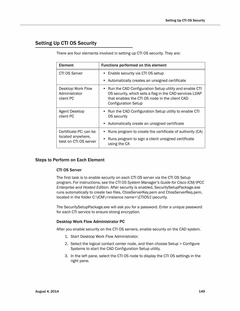
Setting Up CTI OS Security
Setting Up CTI OS Security
There are four elements involved in setting up CTI OS security. They are:
Element Functions performed on this element
CTI OS Server • Enable security via CTI OS setup
• Automatically creates an unsigned certificate
Desktop Work Flow Administrator client PC
• Run the CAD Configuration Setup utility and enable CTI OS security, which sets a flag in the CAD services LDAP that enables the CTI OS node in the client CAD Configuration Setup
Agent Desktop client PC
• Run the CAD Configuration Setup utility to enable CTI OS security
• Automatically create an unsigned certificate
Certificate PC: can be located anywhere, best on CTI OS server
• Runs program to create the certificate of authority (CA)
• Runs program to sign a client unsigned certificate using the CA
Steps to Perform on Each Element
CTI OS Server
The first task is to enable security on each CTI OS server via the CTI OS Setup program. For instructions, see the CTI OS System Manager’s Guide for Cisco ICM/IPCC Enterprise and Hosted Edition. After security is enabled, SecuritySetupPackage.exe runs automatically to create two files, CtiosServerKey.pem and CtiosServerReq.pem, located in the folder C:\ICM\<instance name>\CTIOS1\security.
The SecuritySetupPackage.exe will ask you for a password. Enter a unique password for each CTI service to ensure strong encryption.
Desktop Work Flow Administrator PC
After you enable security on the CTI OS servers, enable security on the CAD system.
1. Start Desktop Work Flow Administrator.
2. Select the logical contact center node, and then choose Setup > Configure Systems to start the CAD Configuration Setup utility.
3. In the left pane, select the CTI OS node to display the CTI OS settings in the right pane.
August 4, 2014 149
Cisco CAD Installation Guide
4. Answer Yes to the question, “Is the CTI OS security setting enabled?” and then click Apply.
This sets a flag in CAD services LDAP to display the CTI OS window whenever the CAD Configuration Setup utility is run on an Agent Desktop PC, thereby making it possible for the SecuritySetupPackage.exe program to run automatically on that agent’s PC.
It also automatically starts the SecuritySetupPackage.exe program, which is installed with every CAD desktop. However, this just creates an unnecessary certificate which can be ignored.
Agent Desktop Client PCs
After Desktop Work Flow Administrator has run the CAD Configuration Setup utility and enabled security, run the CAD Configuration Setup utility on each CAD client PC.
1. Using Windows Explorer, navigate to C:\Program Files\Cisco\Desktop\bin.
2. Locate and then double-click PostInstall.exe to start the CAD Configuration Setup utility.
3. In the left pane, select the CTI OS node to display the CTI OS settings in the right pane.
4. Answer Yes to the question, “Is the CTI OS security setting enabled?” and then click Apply.
SecuritySetupPackage.exe runs and creates two files, CtiosClientkey.pem and Ctiosclientreq.pem, located in C:\Program Files\Cisco Systems\CTIOS Client\Security. These files are used when signing the client certificate.
SecuritySetupPackage.exe will ask you for a password. Enter a unique password for each computer to ensure strong encryption.
Certificate PC
Two programs run on the Certificate PC (on the CAD base services server, at C:\Program Files\Cisco\bin\):
■ CreateSelfSignedCASetupPackage.exe, which creates a certificate of authority for each client box’s certificate.
■ SignCertificateSetupPackage.exe, which signs the client box’s certificate with the certificate of authority
150 August 4, 2014
Setting Up CTI OS Security
Signing Client CTI OS Security Certificates
Follow these steps to sign a CTI OS security certificate for a client box.
1. On the Certificate PC, run CreateSelfSignedCASetupPackage.exe, create a CTIOS Certificate Authority password of between 8 and 30 characters when prompted, and store the resulting files in a secure location.
2. Copy the CtiosClientKey.pem and CtiosClientReq.pem files from the CAD client PC to C:\Program Files\Cisco Systems\CTIOS Client\Security on the Certificate PC, where the CtiosRoot.pem and CtiosRootCert.pem files are stored.
3. On the Certificate PC, run SignCertificateSetupPackage.exe in the same folder where the copied *.pem files are located, select CTI OS Client Certificate Request when prompted, and enter the CTI OS Certificate Authority password you created in Step 1. The program generates a file called CtiosClient.pem if successful, or displays an error message if not successful.
4. Copy the CtiosClient.pem and CtiosRootCert.pem files from the Certificate PC to the C:\Program Files\Cisco Systems\CTIOS Client\Security folder on the CAD client PC.
5. On the CAD client PC, delete the CtiosClientKey.pem file.
6. On the Certificate PC, delete the CtiosClientReq.pem, CtiosClientKey.pem, and CtiosClient.pem files.
7. Repeat Steps 2 through 6 for every CAD client PC in the system.
Signing the Server CTI OS Security Certificate
Follow these steps to sign a CTI OS security certificate for a server box.
1. If you haven’t already done so, on the Certificate box, run CreateSelfSignedCASetupPackage.exe, create a CTIOS Certificate Authority password of between 8 and 30 characters when prompted, and store the resulting files in a secure location.
NOTE: Run CreatSelfSignedCASetupPackage.exe only once. Running it more than once can result in file corruption.
2. Copy the CtiosServerKey.pem and CtiosServerReq.pem files from the CTI OS server (C:\ICM\<instance name>\CTIOS1\security) to the folder on the Certificate PC where the CtiosRoot.pem and CtiosRootCert.pem files are stored.
August 4, 2014 151
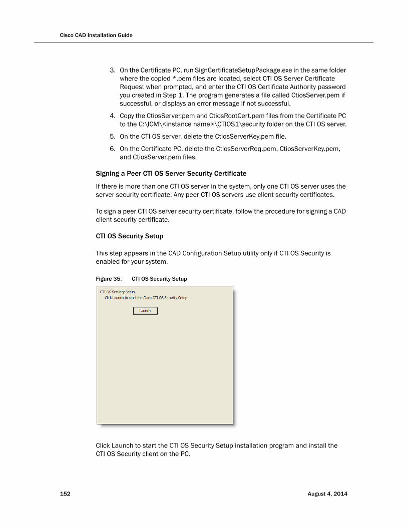
Cisco CAD Installation Guide
3. On the Certificate PC, run SignCertificateSetupPackage.exe in the same folder where the copied *.pem files are located, select CTI OS Server Certificate Request when prompted, and enter the CTI OS Certificate Authority password you created in Step 1. The program generates a file called CtiosServer.pem if successful, or displays an error message if not successful.
4. Copy the CtiosServer.pem and CtiosRootCert.pem files from the Certificate PC to the C:\ICM\<instance name>\CTIOS1\security folder on the CTI OS server.
5. On the CTI OS server, delete the CtiosServerKey.pem file.
6. On the Certificate PC, delete the CtiosServerReq.pem, CtiosServerKey.pem, and CtiosServer.pem files.
Signing a Peer CTI OS Server Security Certificate
If there is more than one CTI OS server in the system, only one CTI OS server uses the server security certificate. Any peer CTI OS servers use client security certificates.
To sign a peer CTI OS server security certificate, follow the procedure for signing a CAD client security certificate.
CTI OS Security Setup
This step appears in the CAD Configuration Setup utility only if CTI OS Security is enabled for your system.
Click Launch to start the CTI OS Security Setup installation program and install the CTI OS Security client on the PC.
Figure 35. CTI OS Security Setup
152 August 4, 2014
Desktop Monitoring Console
Desktop Monitoring Console
Desktop Monitoring Console is a web servlet that allows you to monitor the status of the CAD services and the LDAP Directory Services. It is installed automatically when the CAD base services are installed. To access the console, use the following URL, where <CAD server> is the IP address of the server on which the CAD services are installed:
http://<CAD server>:8088/smc/monitor.jsp
The CAD administrator can hyperlink this URL to the Unified CCE Configuration node in Desktop Administrator for easy access to Desktop Monitoring Console.
Any computer running a CAD service must have the Simple Network Management Protocol (SNMP) component installed in order for Desktop Monitoring Console to be able to monitor the status of that service.
When CAD is not running on a PG, configure the Microsoft SNMP service.
When CAD is running on a PG, Cisco SNMP Agent Management service must be enabled and the Microsoft SNMP service must be disabled. The Microsoft SNMP service and the Cisco SNMP Agent Management service cannot simultaneously be enabled.
Configuring Microsoft SNMP Service for use with CAD
To configure Microsoft SNMP service:
1. On the server where the CAD service(s) is installed, open the Programs and Features control panel.
2. From the button bar on the left of the Programs and Features window, click Turn Windows features on or off.
3. In the Turn Windows features on or off window, select Simple Network Management Protocol (SNMP) from the selection pane and click OK.
4. Close the Programs and Features window.
5. Run services.msc to open the Windows Services list.
6. Right-click SNMP Service and select Properties.
7. In the SNMP Service Properties window, select the Security tab.
a. Under the Accepted Community Names section, click Add. The SNMP Service Configuration window opens.
b. Select READ ONLY from the Community Rights drop-down list, enter public in the Community Name field, then click Add. The public community is added to the Accepted Community Names section.
August 4, 2014 153
Cisco CAD Installation Guide
NOTE: Community names are case sensitive. The word public must be all lowercase.
c. Select one of the following SNMP options.
— Accept SNMP Packets From Any Host
— Accept SNMP Packets From These Hosts
NOTE: If security is a concern, select this option. Using this option enables you to identify one or more specific machines that can send SNMP packets to this server.
d. If you selected Accept SNMP Packets From These Hosts, add the IP addresses for all of the servers on which CAD services are installed.
NOTE: Do not use localhost or any other DNS name. Using DNS names might lead to problems if DNS does not properly resolve the hostnames to IP addresses.
8. Click Apply to save your changes, then OK to close the window.
9. Restart the SNMP service for the changes to take effect.
Configuring Cisco SNMP Agent Management Service for use with CAD
To configure Cisco SNMP:
1. Run mmc /32 to open the Microsoft Management Console window.
2. Choose File > Add/Remove Snap-in.
3. In the Add or Remove Snap-ins window, select Cisco SNMP Agent Management Tool from the Available snap-ins list, and click Add. The Cisco SNMP Agent Management Tool is moved to the Selected snap-ins list.
4. Click OK to close the Add or Remove Snap-ins window.
5. In the left pane of the Microsoft Management Console window, select Cisco SNMP Agent Management.
6. In the right pane, right click Community Names (SNMP...), and select Properties from the drop-down menu.
7. In the Community Names (SNMP...) Properties dialog box, click Add New Community.
a. In the Community Name field, enter public.
NOTE: Community names are case sensitive. The word public must be all lowercase.
b. For SNMP Version, select SNMP v2c.
154 August 4, 2014

Desktop Monitoring Console
c. For Access Rights, select Read Only.
8. Click Save, and then click OK to close the Community Names (SNMP...) Properties dialog box.
9. Close the Microsoft Management Console window.
10. Run services.msc to open the Windows Services list.
11. Restart the Cisco SNMP Agent Management service in order for the changes to take effect.
After configuring SNMP, you must enable SNMP in the CAD Configuration Setup utility. For more information, see "SNMP Configuration" on page 86.
August 4, 2014 155

Cisco CAD Installation Guide
Repairing CAD
If one of the CAD client or server applications is not functioning properly, you can use the Repair function to reinstall it. If you do repair a CAD application, the process automatically repairs any maintenance release (MR), engineering special (ES), and engineering test (ET) that has been installed.
To repair a CAD client or server application:
1. In Windows Control Panel, start the Add or Remove Programs tool.
2. In the list of currently installed programs, locate the CAD application you want to repair.
3. Click the Click here for support information link to display the Support Info dialog box.
4. Click Repair. The program will be reinstalled.
NOTE: If there are any MRs, ESs, or ETs installed, the base release will be reinstalled first, and then each MR, ES, and ET, in ascending order.
156 August 4, 2014
Shutting Down and Restarting Replication
Shutting Down and Restarting Replication
If you have configured your system with Directory Services replication or Recording and Statistics Service replication, you might occasionally need to temporarily shut down replication.
Temporarily shutting down replication is required when you upgrade CAD. You must stop Directory Services replication and Recording and Statistics Service replication prior to starting an upgrade in order to avoid corrupting your CAD services LDAP database.
Temporarily shutting down replication might be required if:
■ You move one of the Directory Services or Recording and Statistics Service instances to another server.
■ One of the Directory Services servers is shut down for two days or more.
When one of the servers in a replicated system is down for an extended time such as this, the remaining Directory Services server experiences high resource usage. The longer that server is down, the higher the resource usage becomes on the remaining server.
August 4, 2014 157
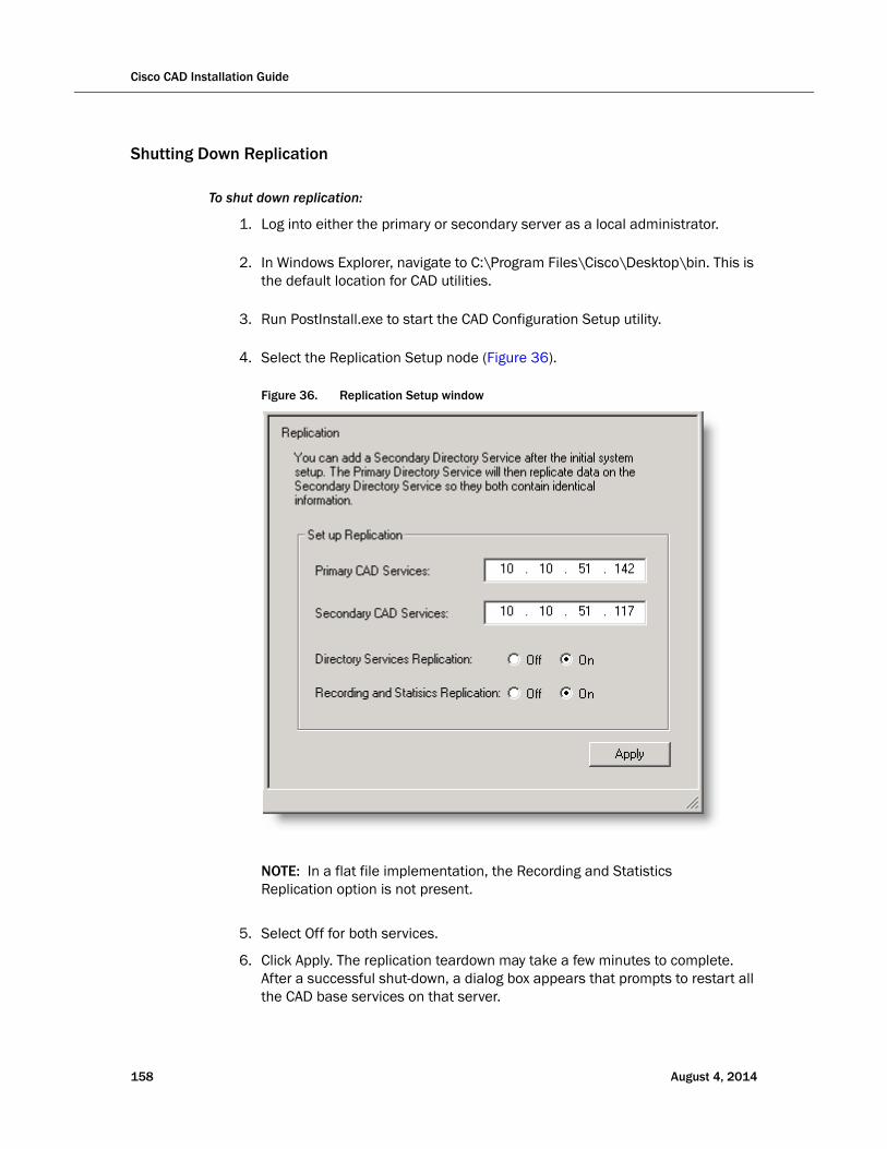
Cisco CAD Installation Guide
Shutting Down Replication
To shut down replication:
1. Log into either the primary or secondary server as a local administrator.
2. In Windows Explorer, navigate to C:\Program Files\Cisco\Desktop\bin. This is the default location for CAD utilities.
3. Run PostInstall.exe to start the CAD Configuration Setup utility.
4. Select the Replication Setup node (Figure 36).
Figure 36. Replication Setup window
NOTE: In a flat file implementation, the Recording and Statistics Replication option is not present.
5. Select Off for both services.
6. Click Apply. The replication teardown may take a few minutes to complete. After a successful shut-down, a dialog box appears that prompts to restart all the CAD base services on that server.
158 August 4, 2014
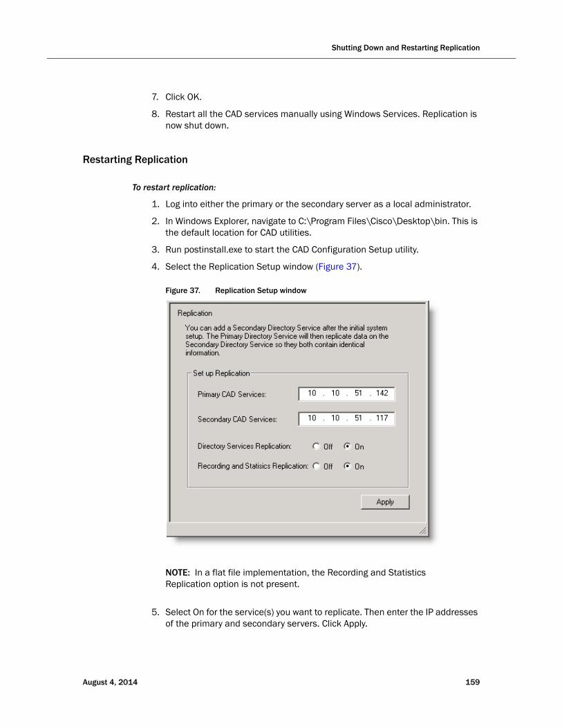
Shutting Down and Restarting Replication
7. Click OK.
8. Restart all the CAD services manually using Windows Services. Replication is now shut down.
Restarting Replication
To restart replication:
1. Log into either the primary or the secondary server as a local administrator.
2. In Windows Explorer, navigate to C:\Program Files\Cisco\Desktop\bin. This is the default location for CAD utilities.
3. Run postinstall.exe to start the CAD Configuration Setup utility.
4. Select the Replication Setup window (Figure 37
Figure 37. Replication Setup window
).
NOTE: In a flat file implementation, the Recording and Statistics Replication option is not present.
5. Select On for the service(s) you want to replicate. Then enter the IP addresses of the primary and secondary servers. Click Apply.
August 4, 2014 159

Cisco CAD Installation Guide
6. Restart CAD services manually using Windows Services. Replication is now re-established between the primary and secondary servers.
160 August 4, 2014

Reinstalling CAD Services in a High Availability System
Reinstalling CAD Services in a High Availability System
If your configuration is a high availability (HA) system, the following procedure must be followed to reinstall the CAD services. This ensures that the LDAP database will not be corrupted when CAD is reinstalled. The desktop applications remain unaffected in this process.
It is recommended that you schedule this activity for a down time to lessen the impact on the contact center.
To reinstall the CAD services in an HA system:
1. On the Side B server, run the CAD Configuration Setup utility (postinstall.exe) and navigate to the Replication node (Figure 30 on page 89). Turn off Directory Services Replication, and click Apply.
2. On the Side B server, uninstall all service releases (SRs) and engineering tests (ETs), if any, and then uninstall the CAD services.
3. On the Side A server, uninstall all SRs and ETs, if any, and then uninstall the CAD services.
4. Restart both servers.
5. Reinstall and configure the CAD services and any SRs and ETs on Side A.
6. Reinstall and configure the CAD services and any SRs and ETs on Side B.
7. Reestablish replication.
a. On the Side B server, run the CAD Configuration Setup utility again, and navigate to the Replication node.
b. Turn on Directory Services replication, enter the Side A and Side B server IP addresses, and then click Apply.
August 4, 2014 161

Cisco CAD Installation Guide
162 August 4, 2014
August 4, 2014
Removal
Removing CAD 9.0
It is recommended that you remove CAD applications in this order:
1. Supervisor Desktop or Agent Desktop
2. Desktop Administrator
3. CAD base services
To remove a CAD application:
1. Open the Add or Remove Programs control panel.
2. Select the application you wish to remove and click Remove. The application is removed.
NOTE: During the uninstallation process, the Microsoft installer might display a message telling you that you should shut down an application that is running. You can shut down the specified application, or ignore the message and continue with the uninstallation.
Removing MRs, ESs, and ETs
If there are maintenance releases (MRs), engineering specials (ESs), and/or engineering tests (ETs) installed on top of the base release, the base release cannot be removed. You must remove the ET first, followed by the MRs and ESs.
To prevent CAD from being uninstalled in the wrong order, once the ET has been removed, the Remove buttons on all but the most recent ES or MR are disabled. As each MR and ES is removed, the Remove button on the next one eligible to be uninstalled is enabled.
This process continues until the base release is able to be removed.
163

Cisco CAD Installation Guide
164 August 4, 2014