Cisco ASR 1001-X Router Specifications€¦ · Cisco ASR 1001-X Router Specifications...
22
Cisco ASR 1001-X Router Specifications This appendix provides the Cisco ASR 1001-X Router specifications. • Cisco ASR 1006 Router Specifications, page 1 • Cisco ASR 1004 Router Specifications, page 6 • Cisco ASR 1002 Router, Cisco ASR 1002-F Router, and Cisco ASR 1002-X Router Specifications, page 10 • Cisco ASR 1013 Router Specifications, page 15 • Cisco ASR 1001-X Router Specifications, page 20 Cisco ASR 1006 Router Specifications This section lists the specifications for the Cisco ASR 1006 Router. The following table lists the Cisco ASR 1006 Router physical specifications. Table 1: Cisco ASR 1006 Router Specifications Specification Description Connects the Cisco ASR 1000 Series RP1, Cisco ASR 1000 Series ESP, Cisco ASR 1000 Series SPA Interface (SIP), SPAs, and power supplies together in the system Midplane Height = 10.5 in. (25.4 cm) Width = 17.25 in.(43.815 cm) Depth = 22.50 in. (57.15 cm) Dimensions (H x W x D) Cisco ASR 1001-X Router Hardware Installation Guide 1
Transcript of Cisco ASR 1001-X Router Specifications€¦ · Cisco ASR 1001-X Router Specifications...

Cisco ASR 1001-X Router Specifications
This appendix provides the Cisco ASR 1001-X Router specifications.
• Cisco ASR 1006 Router Specifications, page 1
• Cisco ASR 1004 Router Specifications, page 6
• Cisco ASR 1002 Router, Cisco ASR 1002-F Router, and Cisco ASR 1002-X Router Specifications,page 10
• Cisco ASR 1013 Router Specifications, page 15
• Cisco ASR 1001-X Router Specifications, page 20
Cisco ASR 1006 Router SpecificationsThis section lists the specifications for the Cisco ASR 1006 Router.
The following table lists the Cisco ASR 1006 Router physical specifications.
Table 1: Cisco ASR 1006 Router Specifications
SpecificationDescription
Connects the CiscoASR 1000 Series RP1, CiscoASR 1000 SeriesESP, Cisco ASR 1000 Series SPA Interface (SIP), SPAs, andpower supplies together in the system
Midplane
Height = 10.5 in. (25.4 cm)
Width = 17.25 in.(43.815 cm)
Depth = 22.50 in. (57.15 cm)
Dimensions (H x W x D)
Cisco ASR 1001-X Router Hardware Installation Guide 1
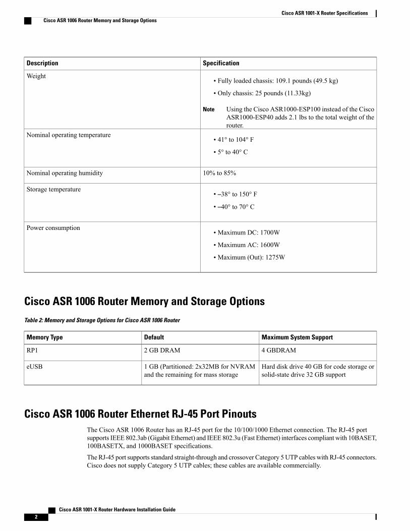
SpecificationDescription
• Fully loaded chassis: 109.1 pounds (49.5 kg)
• Only chassis: 25 pounds (11.33kg)
Using the Cisco ASR1000-ESP100 instead of the CiscoASR1000-ESP40 adds 2.1 lbs to the total weight of therouter.
Note
Weight
• 41° to 104° F
• 5° to 40° C
Nominal operating temperature
10% to 85%Nominal operating humidity
• –38° to 150° F
• –40° to 70° C
Storage temperature
• Maximum DC: 1700W
• Maximum AC: 1600W
• Maximum (Out): 1275W
Power consumption
Cisco ASR 1006 Router Memory and Storage OptionsTable 2: Memory and Storage Options for Cisco ASR 1006 Router
Maximum System SupportDefaultMemory Type
4 GBDRAM2 GB DRAMRP1
Hard disk drive 40 GB for code storage orsolid-state drive 32 GB support
1 GB (Partitioned: 2x32MB for NVRAMand the remaining for mass storage
eUSB
Cisco ASR 1006 Router Ethernet RJ-45 Port PinoutsThe Cisco ASR 1006 Router has an RJ-45 port for the 10/100/1000 Ethernet connection. The RJ-45 portsupports IEEE 802.3ab (Gigabit Ethernet) and IEEE 802.3u (Fast Ethernet) interfaces compliant with 10BASET,100BASETX, and 1000BASET specifications.
The RJ-45 port supports standard straight-through and crossover Category 5 UTP cables with RJ-45 connectors.Cisco does not supply Category 5 UTP cables; these cables are available commercially.
Cisco ASR 1001-X Router Hardware Installation Guide2
Cisco ASR 1001-X Router SpecificationsCisco ASR 1006 Router Memory and Storage Options

The following table shows an RJ-45 port and connector.
——RJ-45 connector1
Cisco ASR 1006 Router MGMT Ethernet Port PinoutsTable 3: RJ-45 Management Ethernet Port Pinouts
DescriptionDirectionSignalPin
Transmit DataOutTX Data+1
Transmit DataOutTX Data–2
Receive DataInRX Data+3
——NC4, 5
Receive DataInRX Data–6
——NC7,8
Cisco ASR 1006 Router BITS Port Signals and PinoutsTable 4: BITS RJ-45 Receptacle Pinouts for Cisco ASR1000-RP1
DescriptionDirectionSignalPin
Receive RingInputRX Ring1
Receive (T1/E1)InputRX2
——N/C3, 4
—UnusedTX Ring5
—UnusedTX6
——N/C7,8
Cisco ASR 1001-X Router Hardware Installation Guide 3
Cisco ASR 1001-X Router SpecificationsCisco ASR 1006 Router MGMT Ethernet Port Pinouts

Table 5: BITS RJ-45 Receptacle Pinouts for Cisco ASR1000-RP2
DescriptionDirectionSignalPin
ReceiveRing/Bidirectional DTI
Input/Bi (DTI)RX Ring1
Receive TIP (T1/E1)Bidirectional DTI
Input/Bi (DTI)RX TIP2
——N/C3, 4
TransmitRing/Bidirectional DTI
OutputTX Ring5
Transmit TIP (T1/E1)Bidirectional DTI
OutputTX6
——N/C7,8
Cisco ASR 1006 Router Console Port Signals and PinoutsTable 6: Console Port Pinouts for Cisco ASR 1006 Router
DescriptionDirectionSignalPin
Request to Send (tied topin 8, CTS)
OutRTS1
Data Terminal Ready(always On)
OutDTR2
Transmit DataOutTXD3
Ring Indicator—GND4
——GND5
Receive DataInRXD6
Data Terminal ReadyInDSR7
Clear to Send (tied to pin1, RTS)
InCTS8
Cisco ASR 1001-X Router Hardware Installation Guide4
Cisco ASR 1001-X Router SpecificationsCisco ASR 1006 Router Console Port Signals and Pinouts
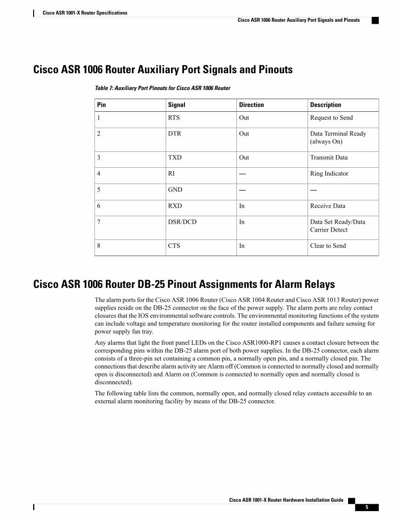
Cisco ASR 1006 Router Auxiliary Port Signals and PinoutsTable 7: Auxiliary Port Pinouts for Cisco ASR 1006 Router
DescriptionDirectionSignalPin
Request to SendOutRTS1
Data Terminal Ready(always On)
OutDTR2
Transmit DataOutTXD3
Ring Indicator—RI4
——GND5
Receive DataInRXD6
Data Set Ready/DataCarrier Detect
InDSR/DCD7
Clear to SendInCTS8
Cisco ASR 1006 Router DB-25 Pinout Assignments for Alarm RelaysThe alarm ports for the Cisco ASR 1006 Router (Cisco ASR 1004 Router and Cisco ASR 1013 Router) powersupplies reside on the DB-25 connector on the face of the power supply. The alarm ports are relay contactclosures that the IOS environmental software controls. The environmental monitoring functions of the systemcan include voltage and temperature monitoring for the router installed components and failure sensing forpower supply fan tray.
Any alarms that light the front panel LEDs on the Cisco ASR1000-RP1 causes a contact closure between thecorresponding pins within the DB-25 alarm port of both power supplies. In the DB-25 connector, each alarmconsists of a three-pin set containing a common pin, a normally open pin, and a normally closed pin. Theconnections that describe alarm activity are Alarm off (Common is connected to normally closed and normallyopen is disconnected) and Alarm on (Common is connected to normally open and normally closed isdisconnected).
The following table lists the common, normally open, and normally closed relay contacts accessible to anexternal alarm monitoring facility by means of the DB-25 connector.
Cisco ASR 1001-X Router Hardware Installation Guide 5
Cisco ASR 1001-X Router SpecificationsCisco ASR 1006 Router Auxiliary Port Signals and Pinouts

Table 8: Cisco ASR 1006 Router DB-25 Alarm Connector Pinout Assignments
SPARENormally Closed(NC)
Normally Open(NO)
Common(CM)
DescriptionSignal
—1412Critical AudibleAlarm
CRTAA
—15316Major AudibleAlarm
MAJAA
—1745Minor AudibleAlarm
MINAA
—18619Critical VisualAlarm
CRTVA
—2078Major VisualAlarm
MAJVA
—21922Minor VisualAlarm
MINVA
10, 11, 12, 13,23, 24, 25
———SPARE—unusedpin reserved forfuture use
SPARE
Cisco ASR 1004 Router SpecificationsThis section lists the specifications for the Cisco ASR 1004 Router.
The following table lists the Cisco ASR 1004 Router physical specifications.
Table 9: Cisco ASR 1004 Router Specifications
SpecificationDescription
Connects the Cisco ASR 1000 Series RP1, ASR 1000 Series ESP,Cisco ASR 1000 Series SPA Interface (SIP), SPAs, and powersupplies together in the system
Midplane
Height = 7 in. (17.8 cm) (4RU rack-mount per EIA RS-310)
Width = 17.25 in. (43.815 cm) (19 inch rack-mount or optional23 Telco rack- mount)
Depth = 22.50 in. (57.15 cm) (including card handles,cable-management brackets and power supply handles)
Dimensions (H x W x D)
Cisco ASR 1001-X Router Hardware Installation Guide6
Cisco ASR 1001-X Router SpecificationsCisco ASR 1004 Router Specifications

SpecificationDescription
• Fully loaded chassis: 50 pounds (22.6796 kg)
• Only chassis: 18 pounds (8.16 kg)
Weight
• 41° to 104° F
• 5° to 40° C
Nominal operating temperature
10% to 85%Nominal operating humidity
• –38° to 150° F
• –40° to 70° C
Storage temperature
• Maximum DC: 1020W
• Maximum AC: 960W
• Maximum (Out): 765W
Power consumption
Cisco ASR 1004 Router Memory and Storage OptionsThe following table lists the hardware memory and storage options supported on the Cisco ASR 1004 Router.
Table 10: Memory and Storage Options for Cisco ASR 1004 Router
Maximum System SupportDefaultMemory Type
4 GBDRAM2 GB DRAMRP1
For mass storage: hard disk drive 40 GBor solid-state drive 32Gb support
1 GB (Partitioned: 2x32MB for NVRAMand the remaining for mass storage
eUSB
Cisco ASR 1004 Router Ethernet RJ-45 Port PinoutsThe Cisco ASR 1004 Router has RJ-45 port for the 10/100/1000 Ethernet connection. The RJ-45 port supportsIEEE 802.3ab (Gigabit Ethernet) and IEEE 802.3u (Fast Ethernet) interfaces compliant with 10BASET,100BASETX, and 1000BASET specifications.
The RJ-45 port supports standard straight-through and crossover Category 5 UTP cables with RJ-45 connectors.Cisco does not supply Category 5 UTP cables; these cables are available commercially.
Cisco ASR 1001-X Router Hardware Installation Guide 7
Cisco ASR 1001-X Router SpecificationsCisco ASR 1004 Router Memory and Storage Options
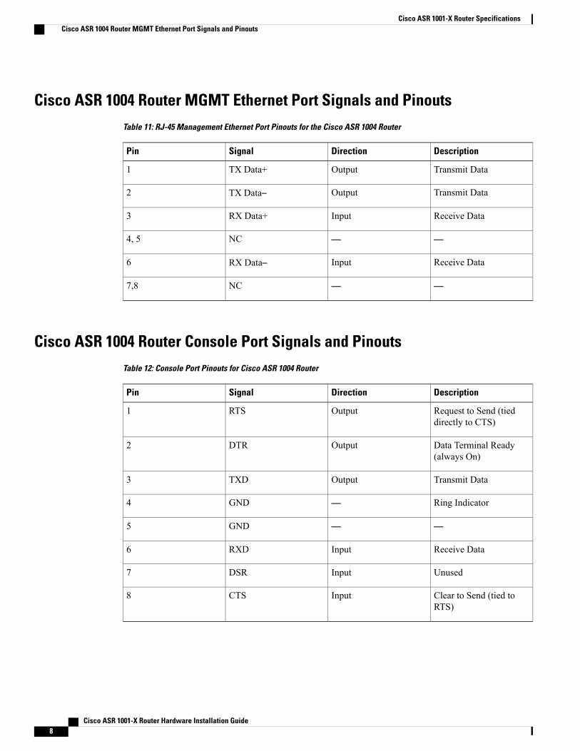
Cisco ASR 1004 Router MGMT Ethernet Port Signals and PinoutsTable 11: RJ-45 Management Ethernet Port Pinouts for the Cisco ASR 1004 Router
DescriptionDirectionSignalPin
Transmit DataOutputTX Data+1
Transmit DataOutputTX Data–2
Receive DataInputRX Data+3
——NC4, 5
Receive DataInputRX Data–6
——NC7,8
Cisco ASR 1004 Router Console Port Signals and PinoutsTable 12: Console Port Pinouts for Cisco ASR 1004 Router
DescriptionDirectionSignalPin
Request to Send (tieddirectly to CTS)
OutputRTS1
Data Terminal Ready(always On)
OutputDTR2
Transmit DataOutputTXD3
Ring Indicator—GND4
——GND5
Receive DataInputRXD6
UnusedInputDSR7
Clear to Send (tied toRTS)
InputCTS8
Cisco ASR 1001-X Router Hardware Installation Guide8
Cisco ASR 1001-X Router SpecificationsCisco ASR 1004 Router MGMT Ethernet Port Signals and Pinouts
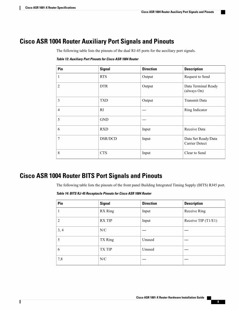
Cisco ASR 1004 Router Auxiliary Port Signals and PinoutsThe following table lists the pinouts of the dual RJ-45 ports for the auxiliary port signals.
Table 13: Auxiliary Port Pinouts for Cisco ASR 1004 Router
DescriptionDirectionSignalPin
Request to SendOutputRTS1
Data Terminal Ready(always On)
OutputDTR2
Transmit DataOutputTXD3
Ring Indicator—RI4
—GND5
Receive DataInputRXD6
Data Set Ready/DataCarrier Detect
InputDSR/DCD7
Clear to SendInputCTS8
Cisco ASR 1004 Router BITS Port Signals and PinoutsThe following table lists the pinouts of the front panel Building Integrated Timing Supply (BITS) RJ45 port.
Table 14: BITS RJ-45 Receptacle Pinouts for Cisco ASR 1004 Router
DescriptionDirectionSignalPin
Receive RingInputRX Ring1
Receive TIP (T1/E1)InputRX TIP2
——N/C3, 4
—UnusedTX Ring5
—UnusedTX TIP6
——N/C7,8
Cisco ASR 1001-X Router Hardware Installation Guide 9
Cisco ASR 1001-X Router SpecificationsCisco ASR 1004 Router Auxiliary Port Signals and Pinouts

Cisco ASR 1004 Router DB-25 Pinout Assignments for Alarm RelaysThe following table lists the common, normally open, and normally closed relay contacts accessible to anexternal alarm monitoring facility by means of the DB-25 connector.
Table 15: Cisco ASR 1004 Router DB-25 Alarm Connector Pinout Assignments
SPARENormally Closed(NC)
Normally Open(NO)
Common(CM)
DescriptionSignal
—1412Critical AudibleAlarm
CRTAA
—15316Major AudibleAlarm
MAJAA
—1745Minor AudibleAlarm
MINAA
—18619Critical VisualAlarm
CRTVA
—2078Major VisualAlarm
MAJVA
—21922Minor VisualAlarm
MINVA
10, 11, 12, 13,23, 24, 25
———SPARE—unusedpin reserved forfuture use
SPARE
Cisco ASR 1002 Router, Cisco ASR 1002-F Router, and Cisco ASR1002-X Router Specifications
This section lists the specifications for the Cisco ASR 1002 Router, Cisco ASR 1002-F Router, and CiscoASR 1002-X Router.
Unless stated otherwise, the specifications for the Cisco ASR 1002-F Router are the same as those for theCisco ASR 1002 Router except where limited by constrained throughput of 2.5G on the Cisco ASR 1002-FRouter.Similarly, most of the specifications for the Cisco ASR 1002-X Router are the same as thespecifications for the Cisco ASR 1002 Router. The differences in specifications have been called out atthe relevant places in this section. Some of the Cisco ASR 1002-X Router specifications that are coveredin this section are for ports that are specific to that router.
Note
Cisco ASR 1001-X Router Hardware Installation Guide10
Cisco ASR 1001-X Router SpecificationsCisco ASR 1004 Router DB-25 Pinout Assignments for Alarm Relays
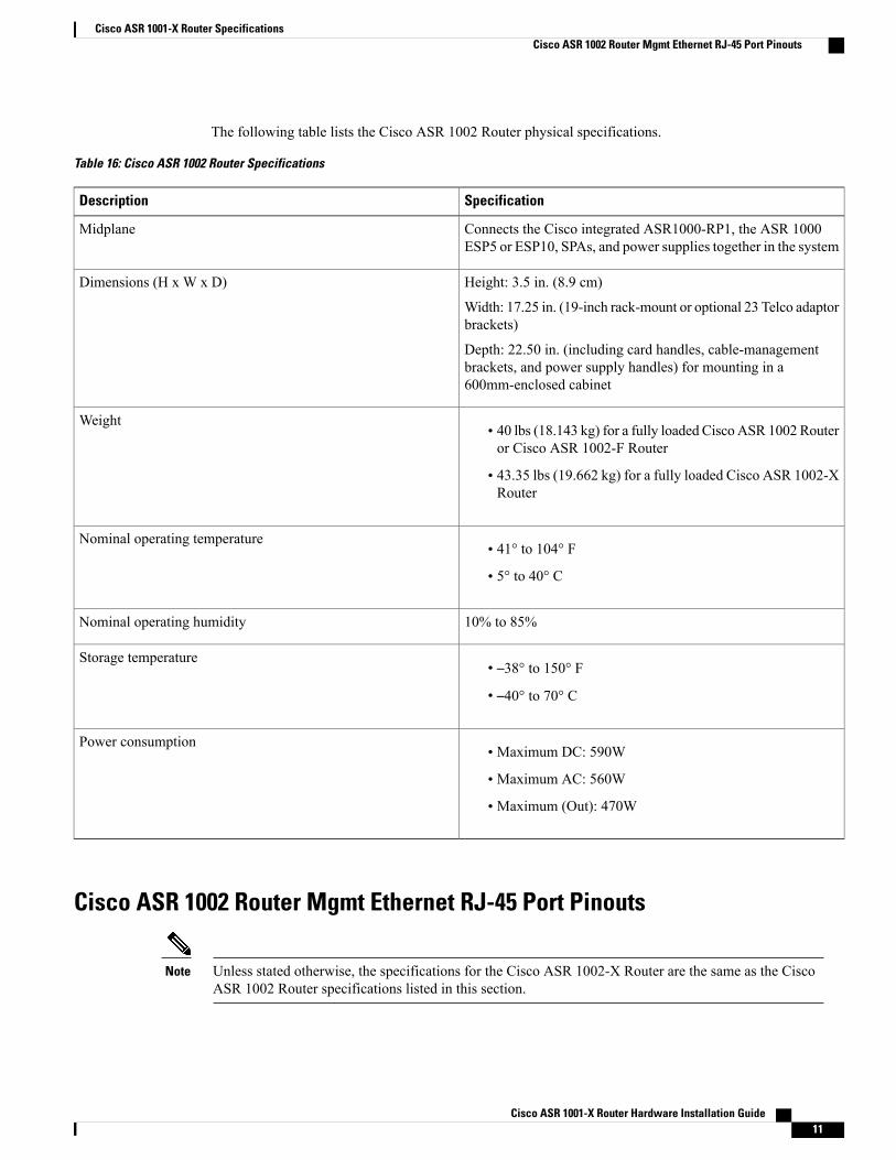
The following table lists the Cisco ASR 1002 Router physical specifications.
Table 16: Cisco ASR 1002 Router Specifications
SpecificationDescription
Connects the Cisco integrated ASR1000-RP1, the ASR 1000ESP5 or ESP10, SPAs, and power supplies together in the system
Midplane
Height: 3.5 in. (8.9 cm)
Width: 17.25 in. (19-inch rack-mount or optional 23 Telco adaptorbrackets)
Depth: 22.50 in. (including card handles, cable-managementbrackets, and power supply handles) for mounting in a600mm-enclosed cabinet
Dimensions (H x W x D)
• 40 lbs (18.143 kg) for a fully loaded Cisco ASR 1002 Routeror Cisco ASR 1002-F Router
• 43.35 lbs (19.662 kg) for a fully loaded Cisco ASR 1002-XRouter
Weight
• 41° to 104° F
• 5° to 40° C
Nominal operating temperature
10% to 85%Nominal operating humidity
• –38° to 150° F
• –40° to 70° C
Storage temperature
• Maximum DC: 590W
• Maximum AC: 560W
• Maximum (Out): 470W
Power consumption
Cisco ASR 1002 Router Mgmt Ethernet RJ-45 Port Pinouts
Unless stated otherwise, the specifications for the Cisco ASR 1002-X Router are the same as the CiscoASR 1002 Router specifications listed in this section.
Note
Cisco ASR 1001-X Router Hardware Installation Guide 11
Cisco ASR 1001-X Router SpecificationsCisco ASR 1002 Router Mgmt Ethernet RJ-45 Port Pinouts

The Cisco ASR 1002 Router has RJ-45 port for the 10/100/1000 Ethernet connections. The RJ-45 port supportsIEEE 802.3ab (Gigabit Ethernet) and IEEE 802.3u (Fast Ethernet) interfaces compliant with 10BASET,100BASETX, and 1000BASET specifications.
The RJ-45 port supports standard straight-through and crossover Category 5 UTP cables with RJ-45 connectors.Cisco does not supply Category 5 UTP cables; these cables are available commercially.
Table 17: Management Ethernet 10/100/1000 RJ-45 Port Pinouts for Cisco ASR 1002 Router
DescriptionDirectionSignalPin
Transmit DataOutputTX Data+1
Transmit DataOutputTX Data–2
Receive DataInputRX Data+3
——NC4, 5
Receive DataInputRX Data–6
——NC7,8
Cisco ASR 1002 Router Console Port Signals and Pinouts
Unless stated otherwise, the specifications for the Cisco ASR 1002-X Router are the same as the CiscoASR 1002 Router specifications listed in this section.
Note
The following table lists the pinout of the dual RJ-45 ports for the front panel console and auxiliary ports.
Table 18: Console Port Pinouts for Cisco ASR 1002 Router
DescriptionDirectionSignalPin
Request to Send (tied toCTS)
OutputRTS1
Data Terminal Ready(always On)
OutputDTR2
Transmit DataOutputTXD3
Ring Indicator—GND4
——GND5
Receive DataInputRXD6
Cisco ASR 1001-X Router Hardware Installation Guide12
Cisco ASR 1001-X Router SpecificationsCisco ASR 1002 Router Console Port Signals and Pinouts

DescriptionDirectionSignalPin
unusedInputDSR7
Clear to Send (tied toRTS)
InputCTS8
Cisco ASR 1002 Router Auxiliary Port Signals and Pinouts
Unless stated otherwise, the specifications for the Cisco ASR 1002-X Router are the same as the CiscoASR 1002 Router specifications listed in this section.
Note
The following table lists the pinout of the dual RJ-45 ports for the auxiliary port signals.
Table 19: Auxiliary Port Pinouts for Cisco ASR 1002 Router
DescriptionDirectionSignalPin
Request to SendOutputRTS1
Data Terminal Ready(always On)
OutputDTR2
Transmit DataOutputTXD3
Ring Indicator—RI4
——GND5
Receive DataInputRXD6
Data Set Ready/DataCarrier Detect
InputDSR/DCD7
Clear to SendInputCTS8
Cisco ASR 1002 Router BITS Port Signals and PinoutsTable 20: BITS RJ-45 Interface Pinouts for Cisco ASR 1002 Router
DescriptionDirectionSignalPin
Receive RingInputRX Ring1
Cisco ASR 1001-X Router Hardware Installation Guide 13
Cisco ASR 1001-X Router SpecificationsCisco ASR 1002 Router Auxiliary Port Signals and Pinouts
DescriptionDirectionSignalPin
Receive TIP (T1/E1)InputRX TIP2
Not used—N/C3, 4
Not used—TX Ring5
Not used—TX TIP6
——N/C7,8
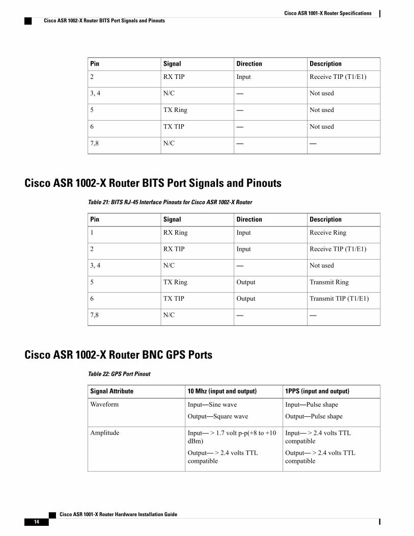
Cisco ASR 1002-X Router BITS Port Signals and PinoutsTable 21: BITS RJ-45 Interface Pinouts for Cisco ASR 1002-X Router
DescriptionDirectionSignalPin
Receive RingInputRX Ring1
Receive TIP (T1/E1)InputRX TIP2
Not used—N/C3, 4
Transmit RingOutputTX Ring5
Transmit TIP (T1/E1)OutputTX TIP6
——N/C7,8
Cisco ASR 1002-X Router BNC GPS PortsTable 22: GPS Port Pinout
1PPS (input and output)10 Mhz (input and output)Signal Attribute
Input—Pulse shape
Output—Pulse shape
Input—Sine wave
Output—Square wave
Waveform
Input— > 2.4 volts TTLcompatible
Output— > 2.4 volts TTLcompatible
Input— > 1.7 volt p-p(+8 to +10dBm)
Output— > 2.4 volts TTLcompatible
Amplitude
Cisco ASR 1001-X Router Hardware Installation Guide14
Cisco ASR 1001-X Router SpecificationsCisco ASR 1002-X Router BITS Port Signals and Pinouts
1PPS (input and output)10 Mhz (input and output)Signal Attribute
50 ohms50 ohmsImpedance
26 microseconds50% duty cyclePulse Width
40 nanosecondsInput—AC coupled
Output—5 nanoseconds
Rise Time
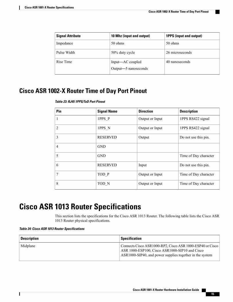
Cisco ASR 1002-X Router Time of Day Port PinoutTable 23: RJ45 1PPS/ToD Port Pinout
DescriptionDirectionSignal NamePin
1PPS RS422 signalOutput or Input1PPS_P1
1PPS RS422 signalOutput or Input1PPS_N2
Do not use this pin.OutputRESERVED3
GND4
Time of Day characterGND5
Do not use this pin.InputRESERVED6
Time of Day characterOutput or InputTOD_P7
Time of Day characterOutput or InputTOD_N8
Cisco ASR 1013 Router SpecificationsThis section lists the specifications for the Cisco ASR 1013 Router. The following table lists the Cisco ASR1013 Router physical specifications.
Table 24: Cisco ASR 1013 Router Specifications
SpecificationDescription
Connects CiscoASR1000-RP2, CiscoASR 1000-ESP40 or CiscoASR 1000-ESP100, Cisco ASR1000-SIP10 and CiscoASR1000-SIP40, and power supplies together in the system
Midplane
Cisco ASR 1001-X Router Hardware Installation Guide 15
Cisco ASR 1001-X Router SpecificationsCisco ASR 1002-X Router Time of Day Port Pinout

SpecificationDescription
Height: 22.8 in. (579.1 cm)
Width: 17.2 in. (437.4 cm)
Depth: 22 in (558.8 cm) with cable-management bracket andpower supply handles included
Dimensions (H x W x D)
• 184.0 lb (83.46 kg) (with redundant AC power supply, SPAand route processor and SIP blank covers, two embeddedservices processors, two route processors, six SIPs, and noSPAs)
• 190.60 pounds (loaded with DC power supplies) (86.45 kg)
• Total with estimated superslot weights with:
◦AC power supplies—202 pounds (91.62 kg)
◦DC power supplies—208.60 (94.61 kg)
Using the Cisco ASR1000-ESP100 instead of the CiscoASR1000-ESP40 adds 2.1 lbs to the total weight of therouter.
Note
Weight
5° to 40° CNominal operating temperature
10% to 85%Nominal operating humidity
• –38° to 150° F
• –40° to 70° C
Storage temperature
• Maximum input (DC): 4,200W
• Maximum input (AC – High Line): 4,000 W
• Maximum output (DC and AC – High Line): 3,390 W
Power consumption (2x Zones)
• Maximum input (DC): 2100W
• Maximum input (AC –High Line): 2,000WMaximum input(AC – Low Line): 1,760W
• Maximum output (DC and AC – High Line): 1,695W
• Maximum output (AC – Low Line): 1,415W
Per Power Supply Power Consumption
Cisco ASR 1001-X Router Hardware Installation Guide16
Cisco ASR 1001-X Router SpecificationsCisco ASR 1013 Router Specifications
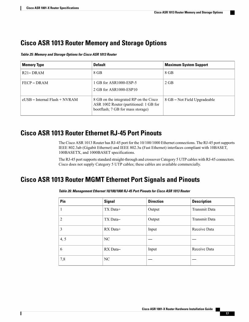
Cisco ASR 1013 Router Memory and Storage OptionsTable 25: Memory and Storage Options for Cisco ASR 1013 Router
Maximum System SupportDefaultMemory Type
8 GB8 GBR21– DRAM
2 GB1 GB for ASR1000-ESP-5
2 GB for ASR1000-ESP10
FECP – DRAM
8 GB – Not Field Upgradeable8 GB on the integrated RP on the CiscoASR 1002 Router (partitioned: 1 GB forbootflash; 7 GB for mass storage)
eUSB – Internal Flash + NVRAM
Cisco ASR 1013 Router Ethernet RJ-45 Port PinoutsThe Cisco ASR 1013 Router has RJ-45 port for the 10/100/1000 Ethernet connections. The RJ-45 port supportsIEEE 802.3ab (Gigabit Ethernet) and IEEE 802.3u (Fast Ethernet) interfaces compliant with 10BASET,100BASETX, and 1000BASET specifications.
The RJ-45 port supports standard straight-through and crossover Category 5 UTP cables with RJ-45 connectors.Cisco does not supply Category 5 UTP cables; these cables are available commercially.
Cisco ASR 1013 Router MGMT Ethernet Port Signals and PinoutsTable 26: Management Ethernet 10/100/1000 RJ-45 Port Pinouts for Cisco ASR 1013 Router
DescriptionDirectionSignalPin
Transmit DataOutputTX Data+1
Transmit DataOutputTX Data–2
Receive DataInputRX Data+3
——NC4, 5
Receive DataInputRX Data–6
——NC7,8
Cisco ASR 1001-X Router Hardware Installation Guide 17
Cisco ASR 1001-X Router SpecificationsCisco ASR 1013 Router Memory and Storage Options
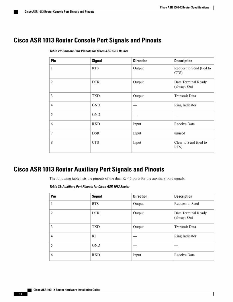
Cisco ASR 1013 Router Console Port Signals and PinoutsTable 27: Console Port Pinouts for Cisco ASR 1013 Router
DescriptionDirectionSignalPin
Request to Send (tied toCTS)
OutputRTS1
Data Terminal Ready(always On)
OutputDTR2
Transmit DataOutputTXD3
Ring Indicator—GND4
——GND5
Receive DataInputRXD6
unusedInputDSR7
Clear to Send (tied toRTS)
InputCTS8
Cisco ASR 1013 Router Auxiliary Port Signals and PinoutsThe following table lists the pinouts of the dual RJ-45 ports for the auxiliary port signals.
Table 28: Auxiliary Port Pinouts for Cisco ASR 1013 Router
DescriptionDirectionSignalPin
Request to SendOutputRTS1
Data Terminal Ready(always On)
OutputDTR2
Transmit DataOutputTXD3
Ring Indicator—RI4
——GND5
Receive DataInputRXD6
Cisco ASR 1001-X Router Hardware Installation Guide18
Cisco ASR 1001-X Router SpecificationsCisco ASR 1013 Router Console Port Signals and Pinouts
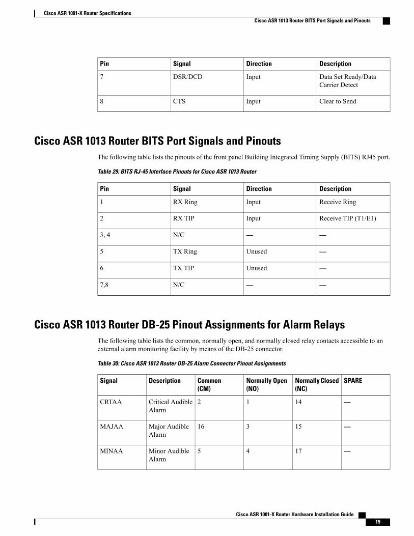
DescriptionDirectionSignalPin
Data Set Ready/DataCarrier Detect
InputDSR/DCD7
Clear to SendInputCTS8
Cisco ASR 1013 Router BITS Port Signals and PinoutsThe following table lists the pinouts of the front panel Building Integrated Timing Supply (BITS) RJ45 port.
Table 29: BITS RJ-45 Interface Pinouts for Cisco ASR 1013 Router
DescriptionDirectionSignalPin
Receive RingInputRX Ring1
Receive TIP (T1/E1)InputRX TIP2
——N/C3, 4
—UnusedTX Ring5
—UnusedTX TIP6
——N/C7,8
Cisco ASR 1013 Router DB-25 Pinout Assignments for Alarm RelaysThe following table lists the common, normally open, and normally closed relay contacts accessible to anexternal alarm monitoring facility by means of the DB-25 connector.
Table 30: Cisco ASR 1013 Router DB-25 Alarm Connector Pinout Assignments
SPARENormally Closed(NC)
Normally Open(NO)
Common(CM)
DescriptionSignal
—1412Critical AudibleAlarm
CRTAA
—15316Major AudibleAlarm
MAJAA
—1745Minor AudibleAlarm
MINAA
Cisco ASR 1001-X Router Hardware Installation Guide 19
Cisco ASR 1001-X Router SpecificationsCisco ASR 1013 Router BITS Port Signals and Pinouts
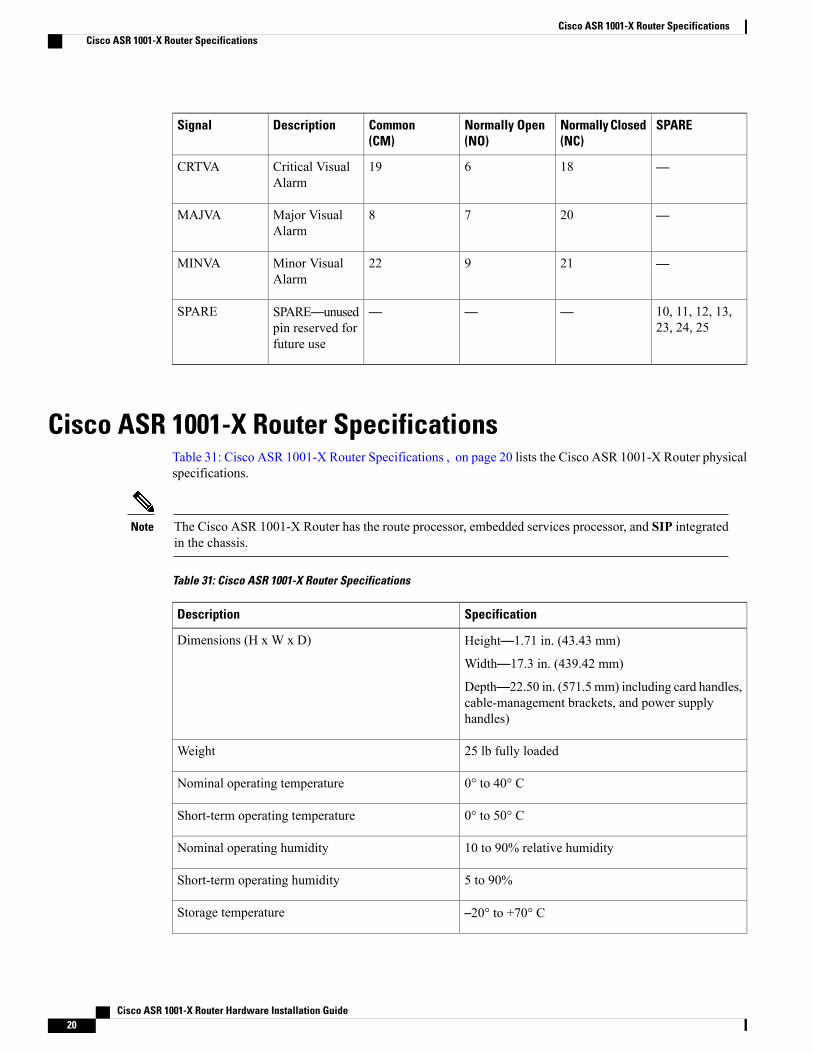
SPARENormally Closed(NC)
Normally Open(NO)
Common(CM)
DescriptionSignal
—18619Critical VisualAlarm
CRTVA
—2078Major VisualAlarm
MAJVA
—21922Minor VisualAlarm
MINVA
10, 11, 12, 13,23, 24, 25
———SPARE—unusedpin reserved forfuture use
SPARE
Cisco ASR 1001-X Router SpecificationsTable 31: Cisco ASR 1001-X Router Specifications , on page 20 lists the Cisco ASR 1001-X Router physicalspecifications.
The Cisco ASR 1001-X Router has the route processor, embedded services processor, and SIP integratedin the chassis.
Note
Table 31: Cisco ASR 1001-X Router Specifications
SpecificationDescription
Height—1.71 in. (43.43 mm)
Width—17.3 in. (439.42 mm)
Depth—22.50 in. (571.5 mm) including card handles,cable-management brackets, and power supplyhandles)
Dimensions (H x W x D)
25 lb fully loadedWeight
0° to 40° CNominal operating temperature
0° to 50° CShort-term operating temperature
10 to 90% relative humidityNominal operating humidity
5 to 90%Short-term operating humidity
–20° to +70° CStorage temperature
Cisco ASR 1001-X Router Hardware Installation Guide20
Cisco ASR 1001-X Router SpecificationsCisco ASR 1001-X Router Specifications
SpecificationDescription
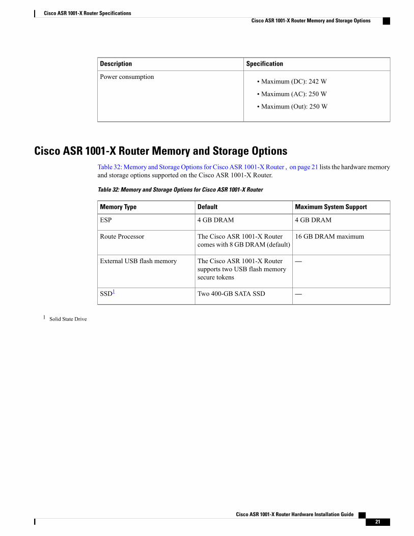
• Maximum (DC): 242 W
• Maximum (AC): 250 W
• Maximum (Out): 250 W
Power consumption
Cisco ASR 1001-X Router Memory and Storage OptionsTable 32:Memory and Storage Options for Cisco ASR 1001-XRouter , on page 21 lists the hardwarememoryand storage options supported on the Cisco ASR 1001-X Router.
Table 32: Memory and Storage Options for Cisco ASR 1001-X Router
Maximum System SupportDefaultMemory Type
4 GB DRAM4 GB DRAMESP
16 GB DRAM maximumThe Cisco ASR 1001-X Routercomes with 8 GBDRAM (default)
Route Processor
—The Cisco ASR 1001-X Routersupports two USB flash memorysecure tokens
External USB flash memory
—Two 400-GB SATA SSDSSD1
1 Solid State Drive
Cisco ASR 1001-X Router Hardware Installation Guide 21
Cisco ASR 1001-X Router SpecificationsCisco ASR 1001-X Router Memory and Storage Options
Cisco ASR 1001-X Router Hardware Installation Guide22
Cisco ASR 1001-X Router SpecificationsCisco ASR 1001-X Router Memory and Storage Options