Cisco Aironet 1570 Series Outdoor Access Points Ordering...
17
© 2015 Cisco and/or its affiliates. All rights reserved. This document is Cisco Public Information. Page 1 of 17 Cisco Aironet 1570 Series Outdoor Access Points Ordering Guide August 2015 Ordering Guide
Transcript of Cisco Aironet 1570 Series Outdoor Access Points Ordering...

© 2015 Cisco and/or its affiliates. All rights reserved. This document is Cisco Public Information. Page 1 of 17
Cisco Aironet 1570 Series Outdoor Access Points
Ordering Guide
August 2015
Ordering Guide
© 2015 Cisco and/or its affiliates. All rights reserved. This document is Cisco Public Information. Page 2 of 17
Contents
1. Introduction .......................................................................................................................................................... 3
2. Cisco Aironet 1570 Series Outdoor Access Points .......................................................................................... 3
3. Cisco Software Subscription .............................................................................................................................. 4 Cable Modem License .......................................................................................................................................... 4 Software Ordering Options.................................................................................................................................... 5
4. Cisco Aironet 1570 Series Components ............................................................................................................ 5 Antennas ............................................................................................................................................................... 5 GPS ...................................................................................................................................................................... 6 Mounting Brackets ................................................................................................................................................ 6 Power .................................................................................................................................................................... 7 AC Power .............................................................................................................................................................. 7 Power over Ethernet ............................................................................................................................................. 8 DC Power.............................................................................................................................................................. 8 SFP ....................................................................................................................................................................... 8 Accessory Kit and Optional Items ......................................................................................................................... 9
RF Cables and Lightning Arrestors .............................................................................................................. 9 Accessory Kit ...................................................................................................................................................... 10
5. Part Numbers for Ordering ............................................................................................................................... 11
6. Cisco Services ................................................................................................................................................... 16 Cisco Technical Services .................................................................................................................................... 16 Cisco Tools for Quoting and Ordering ................................................................................................................. 16
7. Cisco Capital Financing .................................................................................................................................... 16 Flexible Options .................................................................................................................................................. 16
© 2015 Cisco and/or its affiliates. All rights reserved. This document is Cisco Public Information. Page 3 of 17
1. Introduction
This document describes the Cisco Aironet® 1570 Series Outdoor Access Points listed in Table 1. It also describes
the various packaging structures and configurations available for different models. In this document, you’ll also find
part numbers and other information necessary to help you choose and order products.
Table 1. Cisco Aironet 1570 Series Access Points
Model Antenna Type(s) Power Option(s)
AP1572EAC E: External antennas AC: AC power
AP1572IC I: Internal antennas C: Cable backhaul and power-over-cable
AP1572EC E: External antennas C: Cable backhaul and power-over-cable
For more detailed information on Aironet 1570 Series access point products, visit:
http://www.cisco.com/c/en/us/products/wireless/aironet-1570-series/index.html.
2. Cisco Aironet 1570 Series Outdoor Access Points
Aironet 1570 Series Outdoor Access Points (APs) are ideal for both enterprise and carrier-class network operators.
They are the industry’s highest-performing outdoor APs and support the latest Wi-Fi standard, 802.11ac. The 1570
Series APs provide high throughput over a large area with pervasive coverage. A fully operational system contains
the following items:
1. Access point
2. Cable modem right-to-use (RTU) license (1572IC and 1572EC models only)
3. Software
4. External antennas (1572EAC and 1572EC models only)
5. GPS (optional)
6. Mounting brackets
7. Power source
8. Small Form-Factor Pluggable (SFP; optional)
9. Accessories (optional)
Table 2 lists the part numbers for 1570 Series access points in a variety of configurations.
Table 2. Cisco Aironet 1570 Series Models
Part Number Description
AIR-AP1572EAC-x-K9 E: External Antenna, AC Power
AIR-AP1572IC1-x-K9 I: Internal Antenna, C1: Power-over-Cable; NA-DOCSIS 42/ 88 MHz
AIR-AP1572IC2-x-K9 I: Internal Antenna, C2: Power-over-Cable; NA-DOCSIS 85/ 108 MHz
AIR-AP1572IC3-x-K9 I: Internal Antenna, C3: Power-over-Cable; Euro-DOCSIS 65/ 108 MHz
AIR-AP1572IC4-x-K9 I: Internal Antenna, C4: Power-over-Cable; Japan-DOCSIS 65/ 108 MHz
AIR-AP1572EC1-x-K9 E: External Antenna, C1: Power-over-Cable; NA-DOCSIS 42/ 88 MHz
AIR-AP1572EC2-x-K9 E: External Antenna, C2: Power-over-Cable; NA-DOCSIS 85/ 108 MHz
AIR-AP1572EC3-x-K9 E: External Antenna, C3: Power-over-Cable; Euro-DOCSIS 65/ 108 MHz
AIR-AP1572EC4-x-K9 E: External Antenna, C4: Power-over-Cable; Japan-DOCSIS 65/ 108 MHz
Note 1: “x” is a placeholder for the regulatory domain designator. Please visit http://www.cisco.com/go/aironet/compliance (Outdoor Access Points) to determine which regulatory domain is used in your country. Note that the regulatory domain used in your country might differ depending on access point model, and that some models are not available for all countries.
© 2015 Cisco and/or its affiliates. All rights reserved. This document is Cisco Public Information. Page 4 of 17
Note 2: For the USA only, you must use regulatory domain - B instead of the traditional - A. This is due to the recent FCC rule changes that opened up the 5 GHz UNII-1 band for outdoor usage.
Use Table 2 and the remainder of this guide to identify the items that you need for your deployment. Note that
some components are available as a “configurable” option or as a “spare.”
● A “configurable” option ships in the same main box as the AP. For example:
AIR-ACCPMK1570-1 is a “configurable” option and, if so ordered, is shipped alongside the AP in the same
box.
● A “spare” option is denoted with an equals (=) sign at the end of the part number. For example:
AIR-ACCPMK1570-1= is a “spare” and, if so ordered, is shipped in separate packaging.
If making a return or trade-in, you might need to remove any option you installed before returning your access point
to Cisco. Consult your Cisco representative for additional assistance in ordering mesh and other networking
equipment.
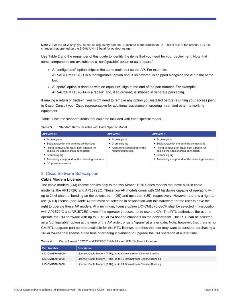
Table 3 lists the standard items that could be included with each specific model.
Table 3. Standard Items Included with Each Specific Model
AP1572EAC AP1572IC AP1572EC
● Access point
● Sealant tape for the antenna connections
● Fitting dome/gland: liquid-tight adapter for sealing the cable ingress connection
● Grounding lug
● Antiseizing compound for the mounting brackets
● DC power connector
● Access point
● Grounding lug
● Antiseizing compound for the mounting brackets
● Access point
● Sealant tape for the antenna connections
● Fitting dome/gland: liquid-tight adapter for sealing the cable ingress connection
● Grounding lug
● Antiseizing compound for the mounting brackets
3. Cisco Software Subscription
Cable Modem License
The cable modem (CM) license applies only to the two Aironet 1570 Series models that have built-in cable
modems, the AP1572IC and AP1572EC. These two AP models come with CM hardware capable of operating with
up to 24x8 channel bonding on the downstream (DS) and upstream (US), respectively. However, there is a right-to-
use (RTU) license (see Table 4) that must be selected in association with this hardware for the user to have the
right to operate these AP models. At a minimum, license option LIC-CM1570-08CH shall be selected in association
with AP1572IC and AP1572EC, even if the operator chooses not to use the CM. The RTU authorizes the user to
operate the CM hardware with up to 8, 16, or 24 bonded channels on the downstream. This RTU can be selected
as a “configurable” option at the time of the AP order, or as a “spare” at a later date. Note, however, that there is no
CM RTU upgrade part number available for this RTU license, and thus the user may want to consider purchasing a
16- or 24-channel license at the time of ordering if planning to upgrade the CM operation at a later time.
Table 4. Cisco Aironet 1572IC and 1572EC Cable Modem RTU Software License
Part Number Description
LIC-CM1570-08CH License: Cable Modem (RTU), up to 8 Downstream Channel Bonding
LIC-CM1570-16CH License: Cable Modem (RTU), up to 16 Downstream Channel Bonding
LIC-CM1570-24CH License: Cable Modem (RTU), up to 24 Downstream Channel Bonding
© 2015 Cisco and/or its affiliates. All rights reserved. This document is Cisco Public Information. Page 5 of 17
Software Ordering Options
The 1570 Series requires, at a minimum, AP software release 8.0MR or later (see Table 5). Traditionally, additional
functions are available for the AP with more recent releases. Please see the applicable release notes for more
information about features available with the latest software releases. You can specify the AP to be loaded and
shipped with the default unified software as either “unified mesh” (SW1570-UM01A01-K9) or “unified local”
(SW1570-UL01A01-K9) mode during the ordering process.
Table 5. Minimum AP Software Releases
Part Number Minimum Software Release
SW1570-UM01A01-K9 SW Cisco AP1570: Unified Mesh (e.g., 8.0.xxx) + IOS (e.g., 15.2.4-yyy); IOS added when available
SW1570-UL01A01-K9 SW Cisco AP1570: Unified Local (e.g., 8.0.xxx) + IOS (e.g., 15.2.4-yyy); IOS added when available
4. Cisco Aironet 1570 Series Components
Antennas
The Aironet 1572IC access point has four internal dual-band (2.4- and 5-GHz) antennas that reside under a sealed
random and cannot be accessed or configured by the user.
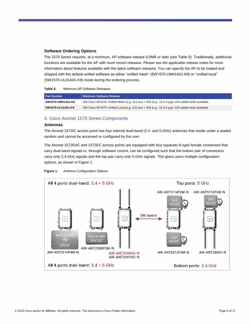
The Aironet 1572EAC and 1572EC access points are equipped with four separate N-type female connectors that
carry dual-band signals or, through software control, can be configured such that the bottom pair of connectors
carry only 2.4-GHz signals and the top pair carry only 5-GHz signals. This gives users multiple configuration
options, as shown in Figure 1.
Figure 1. Antenna Configuration Options
© 2015 Cisco and/or its affiliates. All rights reserved. This document is Cisco Public Information. Page 6 of 17
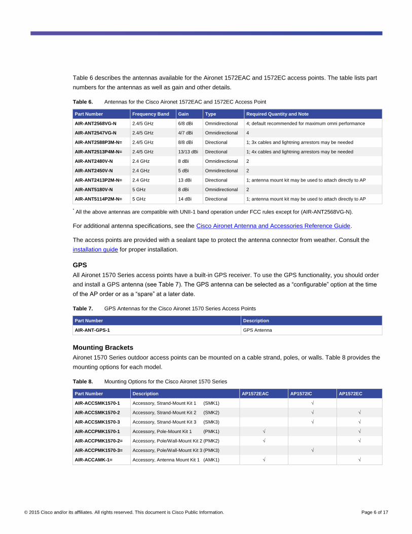
Table 6 describes the antennas available for the Aironet 1572EAC and 1572EC access points. The table lists part
numbers for the antennas as well as gain and other details.
Table 6. Antennas for the Cisco Aironet 1572EAC and 1572EC Access Point
Part Number Frequency Band Gain Type Required Quantity and Note
AIR-ANT2568VG-N 2.4/5 GHz 6/8 dBi Omnidirectional 4; default recommended for maximum omni performance
AIR-ANT2547VG-N 2.4/5 GHz 4/7 dBi Omnidirectional 4
AIR-ANT2588P3M-N= 2.4/5 GHz 8/8 dBi Directional 1; 3x cables and lightning arrestors may be needed
AIR-ANT2513P4M-N= 2.4/5 GHz 13/13 dBi Directional 1; 4x cables and lightning arrestors may be needed
AIR-ANT2480V-N 2.4 GHz 8 dBi Omnidirectional 2
AIR-ANT2450V-N 2.4 GHz 5 dBi Omnidirectional 2
AIR-ANT2413P2M-N= 2.4 GHz 13 dBi Directional 1; antenna mount kit may be used to attach directly to AP
AIR-ANT5180V-N 5 GHz 8 dBi Omnidirectional 2
AIR-ANT5114P2M-N= 5 GHz 14 dBi Directional 1; antenna mount kit may be used to attach directly to AP
* All the above antennas are compatible with UNII-1 band operation under FCC rules except for (AIR-ANT2568VG-N).
For additional antenna specifications, see the Cisco Aironet Antenna and Accessories Reference Guide.
The access points are provided with a sealant tape to protect the antenna connector from weather. Consult the
installation guide for proper installation.
GPS
All Aironet 1570 Series access points have a built-in GPS receiver. To use the GPS functionality, you should order
and install a GPS antenna (see Table 7). The GPS antenna can be selected as a “configurable” option at the time
of the AP order or as a “spare” at a later date.
Table 7. GPS Antennas for the Cisco Aironet 1570 Series Access Points
Part Number Description
AIR-ANT-GPS-1 GPS Antenna
Mounting Brackets
Aironet 1570 Series outdoor access points can be mounted on a cable strand, poles, or walls. Table 8 provides the
mounting options for each model.
Table 8. Mounting Options for the Cisco Aironet 1570 Series
Part Number Description AP1572EAC AP1572IC AP1572EC
AIR-ACCSMK1570-1 Accessory, Strand-Mount Kit 1 (SMK1) √
AIR-ACCSMK1570-2 Accessory, Strand-Mount Kit 2 (SMK2) √ √
AIR-ACCSMK1570-3 Accessory, Strand-Mount Kit 3 (SMK3) √ √
AIR-ACCPMK1570-1 Accessory, Pole-Mount Kit 1 (PMK1) √ √
AIR-ACCPMK1570-2= Accessory, Pole/Wall-Mount Kit 2 (PMK2) √ √
AIR-ACCPMK1570-3= Accessory, Pole/Wall-Mount Kit 3 (PMK3) √
AIR-ACCAMK-1= Accessory, Antenna Mount Kit 1 (AMK1) √ √
© 2015 Cisco and/or its affiliates. All rights reserved. This document is Cisco Public Information. Page 7 of 17
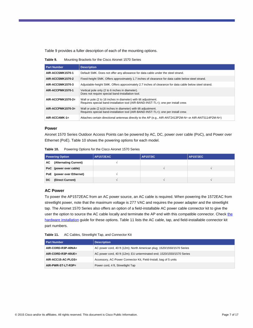
Table 9 provides a fuller description of each of the mounting options.
Table 9. Mounting Brackets for the Cisco Aironet 1570 Series
Part Number Description
AIR-ACCSMK1570-1 Default SMK. Does not offer any allowance for data cable under the steel strand.
AIR-ACCSMK1570-2 Fixed-height SMK. Offers approximately 1.7 inches of clearance for data cable below steel strand.
AIR-ACCSMK1570-3 Adjustable-height SMK. Offers approximately 2.7 inches of clearance for data cable below steel strand.
AIR-ACCPMK1570-1 Vertical pole only (2 to 6 inches in diameter). Does not require special band-installation tool.
AIR-ACCPMK1570-2= Wall or pole (2 to 16 inches in diameter) with tilt adjustment. Requires special band-installation tool (AIR-BAND-INST-TL=); one per install crew.
AIR-ACCPMK1570-3= Wall or pole (2 to16 inches in diameter) with tilt adjustment. Requires special band-installation tool (AIR-BAND-INST-TL=); one per install crew.
AIR-ACCAMK-1= Attaches certain directional antennas directly to the AP (e.g., AIR-ANT2413P2M-N= or AIR-ANT5114P2M-N=)
Power
Aironet 1570 Series Outdoor Access Points can be powered by AC, DC, power over cable (PoC), and Power over
Ethernet (PoE). Table 10 shows the powering options for each model.
Table 10. Powering Options for the Cisco Aironet 1570 Series
Powering Option AP1572EAC AP1572IC AP1572EC
AC (Alternating Current) √
PoC (power over cable) √ √
PoE (power over Ethernet) √
DC (Direct Current) √ √ √
AC Power
To power the AP1572EAC from an AC power source, an AC cable is required. When powering the 1572EAC from
streetlight power, note that the maximum voltage is 277 VAC and requires the power adapter and the streetlight
tap. The Aironet 1570 Series also offers an option of a field-installable AC power cable connector kit to give the
user the option to source the AC cable locally and terminate the AP end with this compatible connector. Check the
hardware installation guide for these options. Table 11 lists the AC cable, tap, and field-installable connector kit
part numbers.
Table 11. AC Cables, Streetlight Tap, and Connector Kit
Part Number Description
AIR-CORD-R3P-40NA= AC power cord, 40 ft (12m); North American plug; 1520/1550/1570 Series
AIR-CORD-R3P-40UE= AC power cord, 40 ft (12m); EU unterminated end; 1520/1550/1570 Series
AIR-ACC15-AC-PLGS= Accessory, AC-Power Connector Kit, Field-Install, bag of 5 units
AIR-PWR-ST-LT-R3P= Power cord, 4 ft, Streetlight Tap

© 2015 Cisco and/or its affiliates. All rights reserved. This document is Cisco Public Information. Page 8 of 17
Power over Ethernet
The AP1572EAC can be powered over the Ethernet connection. Power can be sourced directly from an
appropriately powered Universal Power over Ethernet (UPoE) switch port or from the inline power injector listed in
Table 12.
Table 12. Power Injector for Use with PoE
Part Number Description
AIR-PWRINJ1500-2= 1520/1550/1570 Series Power Injector; for indoor environments only
You must also specify the country type AC power cord for the power injector.
The Aironet 1570 Series access points use a standard RJ-45 Ethernet connector. Cisco does not provide an
Ethernet cable for the 1570 Series. You will need to source an outdoor-rated, Category 5 or better Ethernet cable
and shielded RJ-45 connectors from a local supplier. A liquid-tight gland is provided with the access point to seal
this cable entry point from weather.
DC Power
The Aironet 1570 Series access points support power from an external DC power supply. Check the data sheet for
the associated voltage, current range, and power consumption. A DC terminal block is included with the
AP1572EAC for this purpose. While not common, the cable-powered AP1572IC and AP1572EC can also use DC
power. For that, an accessory kit is available to provide DC terminal block connectors (see the accessories
section/table). Note that these DC connectors are specifically for the Aironet 1570 Series and should not be
interchanged with DC terminal blocks for the previous AP1520, AP1550, or 1530 models. When using DC power,
please consult the hardware installation guide for instructions on how to correctly assemble the connector.
SFP
All the Cisco Aironet 1570 Series Outdoor Access Points support fiber backhaul. The SFP is built into the AP, but
the mechanical interface is external to the AP. A special SFP adapter/gland kit is needed to interface the fiber
cable to the AP. Table 13 lists the SFP and the adapter/gland accessory kit, and Figure 2 illustrates them.
Table 13. SFP Components for use with AP1570
Powering Option Description
AIR-ACC15-SFP-GLD= Accessory, SFP external Gland/Adapter, bag of 5 units
GLC-LX-SM-RGD= 1000BASE-LX single-mode Rugged SFP
GLC-SX-MM-RGD= 1000BASE-SX multi-mode Rugged SFP

© 2015 Cisco and/or its affiliates. All rights reserved. This document is Cisco Public Information. Page 9 of 17
Figure 2. Fitting the Fiber Cable Interface to the AP
Accessory Kit and Optional Items
RF Cables and Lightning Arrestors
For customer convenience, Cisco offers RF cables to remotely attach external antennas to the Cisco Aironet
1572EAC and 1572EC access points. When you use cables between the antenna and these access points, Cisco
recommends that you add lightning arrestors to each port, particularly when the deployment is in an area with high
lightning activity. The lightning arrestor listed here, when properly grounded, provides robust protection against
induced currents in the RF cabling generated by nearby lightning strikes. The lightning arrestor does not protect
against direct lightning strikes on the access point. Table 14 lists and describes the RF cables and lightning
arrestor parts.
Table 14. RF Cables and Lightning Arrestor
Part Number Description
AIR-CAB005LL-N= RF Cable, 5 ft Low-loss, N connectors
AIR-CAB010LL-N= RF Cable, 10 ft Low-loss, N connectors
AIR-ACC245LA-N= Accessory, 2.4 and 5 GHz lightning arrestor, N connector

© 2015 Cisco and/or its affiliates. All rights reserved. This document is Cisco Public Information. Page 10 of 17
Accessory Kit
A number of additional accessories are provided with the Aironet 1570 Series to facilitate the completeness of
certain applications and installation. Table 15 lists the accessory parts and kits.
Table 15. Cisco Aironet 1570 Series Accessories
Part Number Description
AIR-BAND-INST-TL= Accessory, Band installation tool (used for PMK2 and PMK3. Need one per installation crew)
AIR-ACC15-DC-PLGS= Accessory, DC-Power terminal plug/connector, bag of 10 units
AIR-ACC15-GLANDS= Accessory, Metal Cable Glands, bag of 10 units
AIR-ACC15-AC-CAP= Accessory, Cover-cap for AC-Power connector, bag of 10 units, for AP1572EAC/AP1552E
AIR-ACC15-N-CAP= Accessory, Cover-cap for N-connector, bag of 10 units, for AP1572EAC/AP1552E
© 2015 Cisco and/or its affiliates. All rights reserved. This document is Cisco Public Information. Page 11 of 17
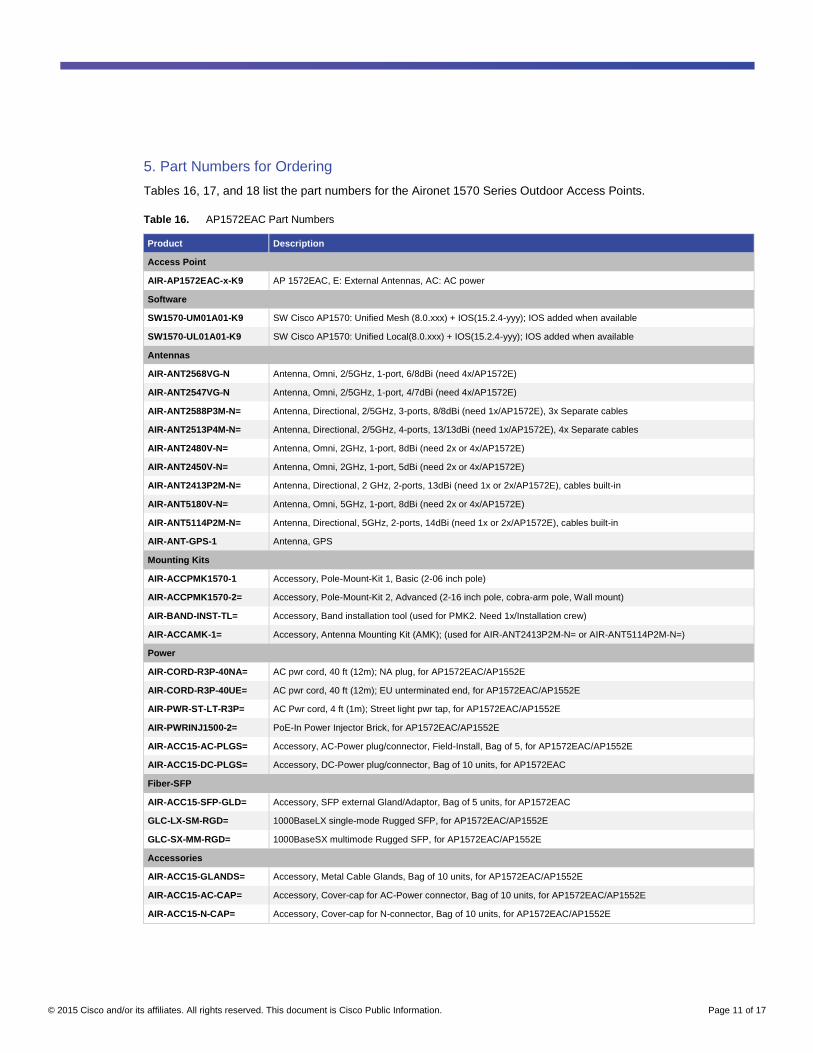
5. Part Numbers for Ordering
Tables 16, 17, and 18 list the part numbers for the Aironet 1570 Series Outdoor Access Points.
Table 16. AP1572EAC Part Numbers
Product Description
Access Point
AIR-AP1572EAC-x-K9 AP 1572EAC, E: External Antennas, AC: AC power
Software
SW1570-UM01A01-K9 SW Cisco AP1570: Unified Mesh (8.0.xxx) + IOS(15.2.4-yyy); IOS added when available
SW1570-UL01A01-K9 SW Cisco AP1570: Unified Local(8.0.xxx) + IOS(15.2.4-yyy); IOS added when available
Antennas
AIR-ANT2568VG-N Antenna, Omni, 2/5GHz, 1-port, 6/8dBi (need 4x/AP1572E)
AIR-ANT2547VG-N Antenna, Omni, 2/5GHz, 1-port, 4/7dBi (need 4x/AP1572E)
AIR-ANT2588P3M-N= Antenna, Directional, 2/5GHz, 3-ports, 8/8dBi (need 1x/AP1572E), 3x Separate cables
AIR-ANT2513P4M-N= Antenna, Directional, 2/5GHz, 4-ports, 13/13dBi (need 1x/AP1572E), 4x Separate cables
AIR-ANT2480V-N= Antenna, Omni, 2GHz, 1-port, 8dBi (need 2x or 4x/AP1572E)
AIR-ANT2450V-N= Antenna, Omni, 2GHz, 1-port, 5dBi (need 2x or 4x/AP1572E)
AIR-ANT2413P2M-N= Antenna, Directional, 2 GHz, 2-ports, 13dBi (need 1x or 2x/AP1572E), cables built-in
AIR-ANT5180V-N= Antenna, Omni, 5GHz, 1-port, 8dBi (need 2x or 4x/AP1572E)
AIR-ANT5114P2M-N= Antenna, Directional, 5GHz, 2-ports, 14dBi (need 1x or 2x/AP1572E), cables built-in
AIR-ANT-GPS-1 Antenna, GPS
Mounting Kits
AIR-ACCPMK1570-1 Accessory, Pole-Mount-Kit 1, Basic (2-06 inch pole)
AIR-ACCPMK1570-2= Accessory, Pole-Mount-Kit 2, Advanced (2-16 inch pole, cobra-arm pole, Wall mount)
AIR-BAND-INST-TL= Accessory, Band installation tool (used for PMK2. Need 1x/Installation crew)
AIR-ACCAMK-1= Accessory, Antenna Mounting Kit (AMK); (used for AIR-ANT2413P2M-N= or AIR-ANT5114P2M-N=)
Power
AIR-CORD-R3P-40NA= AC pwr cord, 40 ft (12m); NA plug, for AP1572EAC/AP1552E
AIR-CORD-R3P-40UE= AC pwr cord, 40 ft (12m); EU unterminated end, for AP1572EAC/AP1552E
AIR-PWR-ST-LT-R3P= AC Pwr cord, 4 ft (1m); Street light pwr tap, for AP1572EAC/AP1552E
AIR-PWRINJ1500-2= PoE-In Power Injector Brick, for AP1572EAC/AP1552E
AIR-ACC15-AC-PLGS= Accessory, AC-Power plug/connector, Field-Install, Bag of 5, for AP1572EAC/AP1552E
AIR-ACC15-DC-PLGS= Accessory, DC-Power plug/connector, Bag of 10 units, for AP1572EAC
Fiber-SFP
AIR-ACC15-SFP-GLD= Accessory, SFP external Gland/Adaptor, Bag of 5 units, for AP1572EAC
GLC-LX-SM-RGD= 1000BaseLX single-mode Rugged SFP, for AP1572EAC/AP1552E
GLC-SX-MM-RGD= 1000BaseSX multimode Rugged SFP, for AP1572EAC/AP1552E
Accessories
AIR-ACC15-GLANDS= Accessory, Metal Cable Glands, Bag of 10 units, for AP1572EAC/AP1552E
AIR-ACC15-AC-CAP= Accessory, Cover-cap for AC-Power connector, Bag of 10 units, for AP1572EAC/AP1552E
AIR-ACC15-N-CAP= Accessory, Cover-cap for N-connector, Bag of 10 units, for AP1572EAC/AP1552E
© 2015 Cisco and/or its affiliates. All rights reserved. This document is Cisco Public Information. Page 12 of 17
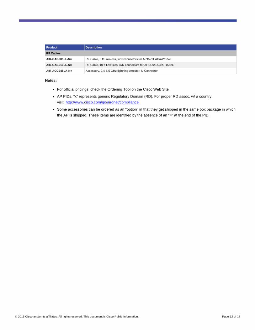
Product Description
RF Cables
AIR-CAB005LL-N= RF Cable, 5 ft Low-loss, w/N connectors for AP1572EAC/AP1552E
AIR-CAB010LL-N= RF Cable, 10 ft Low-loss, w/N connectors for AP1572EAC/AP1552E
AIR-ACC245LA-N= Accessory, 2.4 & 5 GHz lightning Arrestor, N-Connector
Notes:
● For official pricings, check the Ordering Tool on the Cisco Web Site
● AP PIDs, "x" represents generic Regulatory Domain (RD). For proper RD assoc. w/ a country,
visit: http://www.cisco.com/go/aironet/compliance
● Some accessories can be ordered as an "option" in that they get shipped in the same box package in which
the AP is shipped. These items are identified by the absence of an "=" at the end of the PID.

© 2015 Cisco and/or its affiliates. All rights reserved. This document is Cisco Public Information. Page 13 of 17
Table 17. AP1572IC Part Numbers
Product Description
Access Point
AIR-AP1572IC1-x-K9 AP 1572IC1, I: Internal Antennas, C1: Cable Backhaul; NA-DOCSIS 42/88 MHz
AIR-AP1572IC2-x-K9 AP 1572IC2, I: Internal Antennas, C2: Cable Backhaul; NA-DOCSIS 85/108 MHz
AIR-AP1572IC3-x-K9 AP 1572IC3, I: Internal Antennas, C3: Cable Backhaul; Euro-DOCSIS 65/108 MHz
AIR-AP1572IC4-x-K9 AP 1572IC4, I: Internal Antennas, C4: Cable Bachhaul; Japan-DOCSIS 65/108 MHz
Part Number Description
CM RTU License
LIC-CM1570-08CH License: Cable Modem Right-to-Use (RTU), up to 8 Downstream Channel Bonding
LIC-CM1570-16CH License: Cable Modem Right-to-Use (RTU), up to 16 Downstream Channel Bonding
LIC-CM1570-24CH License: Cable Modem Right-to-Use (RTU), up to 24 Downstream Channel Bonding
Software
SW1570-UM01A01-K9 SW Cisco AP1570: Unified Mesh (8.0.xxx) + IOS(15.2.4-yyy); IOS added when available
SW1570-UL01A01-K9 SW Cisco AP1570: Unified Local (8.0.xxx) + IOS(15.2.4-yyy); IOS added when available
Antennas
AIR-ANT-GPS-1 Antenna, GPS
Mounting Kits
AIR-ACCSMK1570-1 ($0 "option") Accessory, Strand-Mount-Kit 1, Short, no data-cable clearance, for AP1572IC
AIR-ACCSMK1570-2 Accessory, Strand-Mount-Kit 2, Tall, approx. 1.7" data cable clearance, for AP1572IC
AIR-ACCSMK1570-3 Accessory, Strand-Mount-Kit 3, Adjustable, approx. 2.7" data cable clearance, for AP1572IC
AIR-ACCPMK1570-3= Accessory, Pole-Mount-Kit 3, Horizontal, 2-16' pole, cobra-arm, Wall mount),for AP1572IC
AIR-BAND-INST-TL= Band installation tool (used for PMK3. Need 1x/Installation crew)
Fiber-SFP
AIR-ACC15-SFP-GLD= Accessory, SFP external Gland/Adaptor, Bag of 5 units, for AP1572IC
GLC-LX-SM-RGD= 1000BaseLX single-mode Rugged SFP, for AP1572IC
GLC-SX-MM-RGD= 1000BaseSX multimode Rugged SFP, for AP1572IC
Accessories
AIR-ACC15-GLANDS= Accessory, Metal Cable Glands, Bag of 10 units, for AP1572IC
AIR-ACC15-DC-PLGS= Accessory, DC-Power connector, Bag of 10 units, for AP1572IC
Notes:
● For official pricings, check the Ordering Tool on the Cisco Web Site
● AP PIDs, "x" represents generic Regulatory Domain (RD). For proper RD assoc. w/ a country,
visit: http://www.cisco.com/go/aironet/compliance
● Some accessories can be ordered as an "option" in that they get shipped in the same box package in which
the AP is shipped. These items are identified by the absence of an "=" at the end of the PID.
© 2015 Cisco and/or its affiliates. All rights reserved. This document is Cisco Public Information. Page 14 of 17
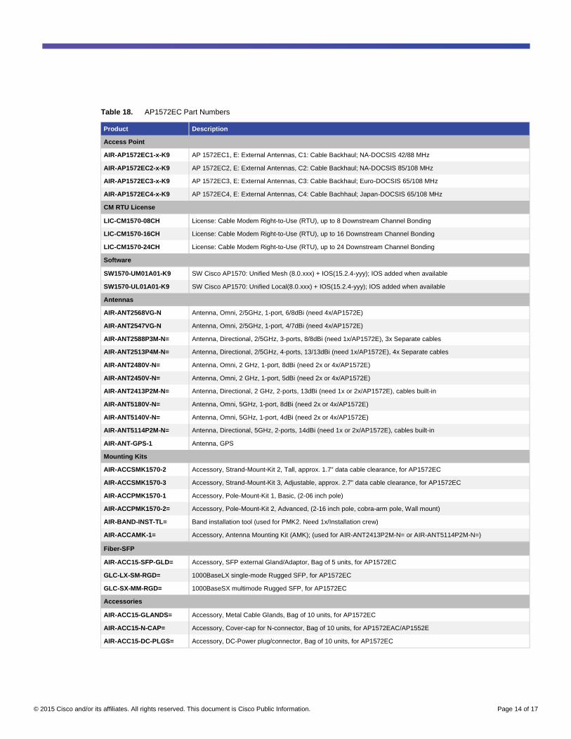
Table 18. AP1572EC Part Numbers
Product Description
Access Point
AIR-AP1572EC1-x-K9 AP 1572EC1, E: External Antennas, C1: Cable Backhaul; NA-DOCSIS 42/88 MHz
AIR-AP1572EC2-x-K9 AP 1572EC2, E: External Antennas, C2: Cable Backhaul; NA-DOCSIS 85/108 MHz
AIR-AP1572EC3-x-K9 AP 1572EC3, E: External Antennas, C3: Cable Backhaul; Euro-DOCSIS 65/108 MHz
AIR-AP1572EC4-x-K9 AP 1572EC4, E: External Antennas, C4: Cable Bachhaul; Japan-DOCSIS 65/108 MHz
CM RTU License
LIC-CM1570-08CH License: Cable Modem Right-to-Use (RTU), up to 8 Downstream Channel Bonding
LIC-CM1570-16CH License: Cable Modem Right-to-Use (RTU), up to 16 Downstream Channel Bonding
LIC-CM1570-24CH License: Cable Modem Right-to-Use (RTU), up to 24 Downstream Channel Bonding
Software
SW1570-UM01A01-K9 SW Cisco AP1570: Unified Mesh (8.0.xxx) + IOS(15.2.4-yyy); IOS added when available
SW1570-UL01A01-K9 SW Cisco AP1570: Unified Local(8.0.xxx) + IOS(15.2.4-yyy); IOS added when available
Antennas
AIR-ANT2568VG-N Antenna, Omni, 2/5GHz, 1-port, 6/8dBi (need 4x/AP1572E)
AIR-ANT2547VG-N Antenna, Omni, 2/5GHz, 1-port, 4/7dBi (need 4x/AP1572E)
AIR-ANT2588P3M-N= Antenna, Directional, 2/5GHz, 3-ports, 8/8dBi (need 1x/AP1572E), 3x Separate cables
AIR-ANT2513P4M-N= Antenna, Directional, 2/5GHz, 4-ports, 13/13dBi (need 1x/AP1572E), 4x Separate cables
AIR-ANT2480V-N= Antenna, Omni, 2 GHz, 1-port, 8dBi (need 2x or 4x/AP1572E)
AIR-ANT2450V-N= Antenna, Omni, 2 GHz, 1-port, 5dBi (need 2x or 4x/AP1572E)
AIR-ANT2413P2M-N= Antenna, Directional, 2 GHz, 2-ports, 13dBi (need 1x or 2x/AP1572E), cables built-in
AIR-ANT5180V-N= Antenna, Omni, 5GHz, 1-port, 8dBi (need 2x or 4x/AP1572E)
AIR-ANT5140V-N= Antenna, Omni, 5GHz, 1-port, 4dBi (need 2x or 4x/AP1572E)
AIR-ANT5114P2M-N= Antenna, Directional, 5GHz, 2-ports, 14dBi (need 1x or 2x/AP1572E), cables built-in
AIR-ANT-GPS-1 Antenna, GPS
Mounting Kits
AIR-ACCSMK1570-2 Accessory, Strand-Mount-Kit 2, Tall, approx. 1.7" data cable clearance, for AP1572EC
AIR-ACCSMK1570-3 Accessory, Strand-Mount-Kit 3, Adjustable, approx. 2.7" data cable clearance, for AP1572EC
AIR-ACCPMK1570-1 Accessory, Pole-Mount-Kit 1, Basic, (2-06 inch pole)
AIR-ACCPMK1570-2= Accessory, Pole-Mount-Kit 2, Advanced, (2-16 inch pole, cobra-arm pole, Wall mount)
AIR-BAND-INST-TL= Band installation tool (used for PMK2. Need 1x/Installation crew)
AIR-ACCAMK-1= Accessory, Antenna Mounting Kit (AMK); (used for AIR-ANT2413P2M-N= or AIR-ANT5114P2M-N=)
Fiber-SFP
AIR-ACC15-SFP-GLD= Accessory, SFP external Gland/Adaptor, Bag of 5 units, for AP1572EC
GLC-LX-SM-RGD= 1000BaseLX single-mode Rugged SFP, for AP1572EC
GLC-SX-MM-RGD= 1000BaseSX multimode Rugged SFP, for AP1572EC
Accessories
AIR-ACC15-GLANDS= Accessory, Metal Cable Glands, Bag of 10 units, for AP1572EC
AIR-ACC15-N-CAP= Accessory, Cover-cap for N-connector, Bag of 10 units, for AP1572EAC/AP1552E
AIR-ACC15-DC-PLGS= Accessory, DC-Power plug/connector, Bag of 10 units, for AP1572EC
© 2015 Cisco and/or its affiliates. All rights reserved. This document is Cisco Public Information. Page 15 of 17
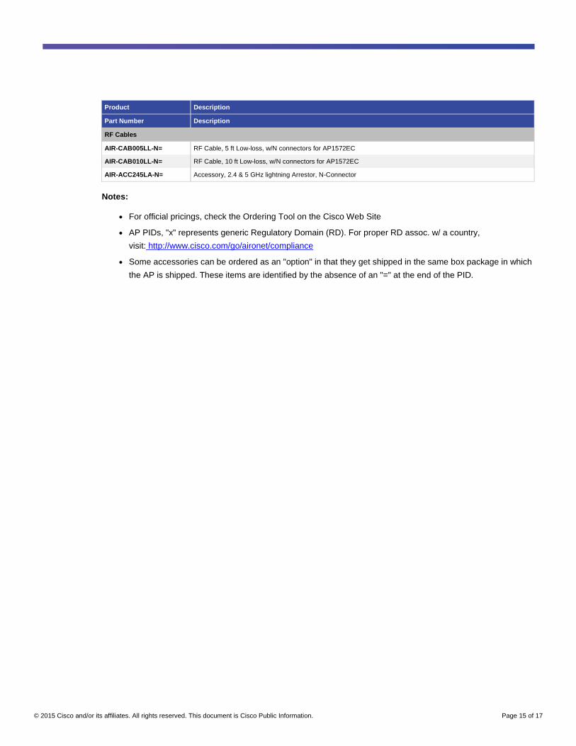
Product Description
Part Number Description
RF Cables
AIR-CAB005LL-N= RF Cable, 5 ft Low-loss, w/N connectors for AP1572EC
AIR-CAB010LL-N= RF Cable, 10 ft Low-loss, w/N connectors for AP1572EC
AIR-ACC245LA-N= Accessory, 2.4 & 5 GHz lightning Arrestor, N-Connector
Notes:
● For official pricings, check the Ordering Tool on the Cisco Web Site
● AP PIDs, "x" represents generic Regulatory Domain (RD). For proper RD assoc. w/ a country,
visit: http://www.cisco.com/go/aironet/compliance
● Some accessories can be ordered as an "option" in that they get shipped in the same box package in which
the AP is shipped. These items are identified by the absence of an "=" at the end of the PID.

© 2015 Cisco and/or its affiliates. All rights reserved. This document is Cisco Public Information. Page 16 of 17
6. Cisco Services
Cisco Technical Services
Table 19 lists Cisco Technical Services for the Aironet 1570 Series Outdoor Access Points.
Table 19. Cisco Technical Services
Service Description and Features
Cisco SMARTnet® Service ● Next-business-day, 8 x 5 x 4, 24 x 7 x 4, and 24 x 7 x 2 advance hardware replacement
1 and onsite parts
replacement and installation available
● Global access to the Cisco Technical Assistance Center (TAC) 24 hours a day
● Unrestricted access to the extensive Cisco.com resources, communities, and tools
● Ongoing operating system software updates2 within a software licensed feature set, if any
● Proactive diagnostics and real-time alerts on Smart Call Home-enabled devices
Cisco Smart Foundation Service
● Next-business-day advance hardware replacement as available
● Business-hours access to SMB Cisco TAC (access levels vary by region)
● Access to Cisco.com SMB knowledge base
● Online technical resources through Smart Foundation Portal
● Operating system software bug fixes and patches, if applicable
1 Advance hardware replacement is available in various service-level combinations. For example, 8 x 5 x next business day (NBD) indicates that shipment will be initiated during the standard 8-hour business day, 5 days a week (the generally accepted business days within the relevant region), with NBD delivery. Where NBD is not available, same-day shipment is provided. Restrictions apply; please review the appropriate SMARTnet service descriptions for details.
2 Cisco operating system updates include maintenance releases, minor updates, and major updates within the licensed feature set, if applicable.
For more information about Cisco Technical Services, visit http://www.cisco.com/go/ts.
Cisco Tools for Quoting and Ordering
To place an order, visit the Cisco ordering website at http://www.cisco.com/en/US/ordering/index.shtml
7. Cisco Capital Financing
The significant benefits offered by the Aironet 1570 Series Outdoor Access Points make them the natural choice
for outdoor Wi-Fi connectivity. As with any technology investment, you have to consider the affordability of the new
system. Financing from Cisco Capital® can make this easier. Whether through flexible repayments matching
expenditure to benefit, mitigating cash flow issues, or negating capital expenditure with an operating lease, we can
give you access to the right technology for your business, when you need it.
Flexible Options
Cisco Capital can usually help remove or reduce barriers preventing you from obtaining the technology that can
most benefit your business. Cisco Capital can:
● Remove cash flow issues, allowing you to spread the cost of your investment over a number of years
● Offer you flexible repayment terms matching expenditure to benefits, which means that payments can
be timed to coincide with business benefits that may be seen later in the project, or deferred to meet your
budget cycle
● Turn capital expenditures into operating expenditures through an operating lease that enables you to
benefit from the value of the technology up-front
● Offer you a sale and lease-back arrangement (where available) that softens the initial costs by taking on
existing commitments that may be attached to legacy equipment

© 2015 Cisco and/or its affiliates. All rights reserved. This document is Cisco Public Information. Page 17 of 17
For more information about Cisco Capital Financing, visit:
http://www.cisco.com/cisco/web/UK/products/ciscocapital/why_finance.html#WJwjw1LSGg3CmUrd.97
Printed in USA C07-733334-02 08/15