Cisco 4G LTE Software Configuration · PDF fileForUMTS,HSPA+and HSPA: •800MHz...
135
Cisco 4G LTE Software Configuration Guide First Published: 2012-03-16 Last Modified: 2017-12-22 Cisco 4G LTE Software Configuration This document provides an overview of the software features and configuration information for Cisco Fourth-Generation (4G) Long-Term Evolution (LTE) Wireless WAN (WWAN) Enhanced High-Speed WAN Interface Cards ( EHWIC-4G-LTEs), Cisco 819 Series 4G LTE ISRs, Cisco C880 Series 4G LTE ISRs and Cisco C890 Series 4G LTE ISRs. Cisco EHWIC-4G-LTEs are single-wide 4G Wireless WAN (WWAN) EHWICs supported on Cisco Integrated Services Router Generation 2 (ISR G2). For Cisco EHWIC-4G-LTE SKUs, faceplate, and LED descriptions, see the Cisco 4G LTE Hardware Installation Guide. Finding Feature Information Your software release may not support all the features documented in this module. For the latest caveats and feature information, see Bug Search Tool and the release notes for your platform and software release. To find information about the features documented in this module, and to see a list of the releases in which each feature is supported, see the feature information table. Use Cisco Feature Navigator to find information about platform support and Cisco software image support. To access Cisco Feature Navigator, go to www.cisco.com/go/cfn. An account on Cisco.com is not required. Prerequisites for Configuring Cisco 4G LTE • You must have 4G LTE network coverage where your router is physically placed. For a complete list of supported carriers, see the product data sheet. • You must subscribe to a service plan with a wireless service provider and obtain a Subscriber Identity Module (SIM) card. • You must install the SIM card before configuring the 4G LTE Wireless WAN EHWIC or Cisco 819 router. • The standalone antenna that supports GPS capabilities must be installed for the GPS feature to work. See the Cisco 4G Indoor/Outdoor Active GPS Antenna (GPS-ACT-ANTM-SMA) (http://www.cisco.com/en/US/docs/routers/access/wireless/hardware/notes/gps_ant.html)document for installation information. • Both GPS and NMEA features must be configured for GPS coordinates to be obtained. Restrictions for Configuring Cisco 4G LTE Follow these restrictions and usage guideline while configuring Cisco 4G LTE: • Currently, cellular networks support only user initiated bearer establishment. Cisco 4G LTE Software Configuration Guide 1
Transcript of Cisco 4G LTE Software Configuration · PDF fileForUMTS,HSPA+and HSPA: •800MHz...

Cisco 4G LTE Software Configuration Guide
First Published: 2012-03-16
Last Modified: 2017-12-22
Cisco 4G LTE Software ConfigurationThis document provides an overview of the software features and configuration information for CiscoFourth-Generation (4G) Long-Term Evolution (LTE)WirelessWAN (WWAN) Enhanced High-SpeedWANInterface Cards ( EHWIC-4G-LTEs), Cisco 819 Series 4G LTE ISRs, Cisco C880 Series 4G LTE ISRs andCisco C890 Series 4G LTE ISRs. Cisco EHWIC-4G-LTEs are single-wide 4G Wireless WAN (WWAN)EHWICs supported on Cisco Integrated Services Router Generation 2 (ISRG2). For Cisco EHWIC-4G-LTESKUs, faceplate, and LED descriptions, see the Cisco 4G LTE Hardware Installation Guide.
Finding Feature InformationYour software release may not support all the features documented in this module. For the latest caveats andfeature information, see Bug Search Tool and the release notes for your platform and software release. Tofind information about the features documented in this module, and to see a list of the releases in which eachfeature is supported, see the feature information table.
Use Cisco Feature Navigator to find information about platform support and Cisco software image support.To access Cisco Feature Navigator, go to www.cisco.com/go/cfn. An account on Cisco.com is not required.
Prerequisites for Configuring Cisco 4G LTE• You must have 4G LTE network coverage where your router is physically placed. For a complete listof supported carriers, see the product data sheet.
• You must subscribe to a service plan with a wireless service provider and obtain a Subscriber IdentityModule (SIM) card.
• You must install the SIM card before configuring the 4G LTE Wireless WAN EHWIC or Cisco 819router.
• The standalone antenna that supports GPS capabilities must be installed for the GPS feature to work.See the Cisco 4G Indoor/Outdoor Active GPS Antenna (GPS-ACT-ANTM-SMA)(http://www.cisco.com/en/US/docs/routers/access/wireless/hardware/notes/gps_ant.html)document forinstallation information.
• Both GPS and NMEA features must be configured for GPS coordinates to be obtained.
Restrictions for Configuring Cisco 4G LTEFollow these restrictions and usage guideline while configuring Cisco 4G LTE:
• Currently, cellular networks support only user initiated bearer establishment.
Cisco 4G LTE Software Configuration Guide 1

• Due to the shared nature of wireless communications, the experienced throughput varies depending onthe number of active users or congestion in a given network.
• Cellular networks have higher latency compared to wired networks. Latency rates depend on thetechnology and carrier. Latency may be higher because of network congestion. Latency also dependson the signal conditions and can be higher because of network congestion.
• Any restrictions that are part of the terms of service from your carrier.
• SMS—Only one text message up to 160 characters to one recipient at a time is supported. Larger textsare automatically truncated to the proper size before being sent.
• For the router that runs the SNMP agent, you must configure appropriate access control (for example,SNMP-server community) using the Cisco IOS CLI for the NMS and agent to work properly.
• It is strongly recommended that you configure SNMPV3with authentication/privacywhen implementingSNMP SET operation.
Information about Configuring Cisco 4G LTE
Overview of Cisco 4G LTECisco EHWIC-4G-LTEs are single-wide Wireless WAN (WWAN) EHWICs supported on Cisco 1110 Seriesrouters. Cisco EHWIC-4G-LTEs operate over Fourth-Generation Long-Term Evolution (4G LTE) cellularnetworks and Third-Generation (3G) cellular networks. The Cisco 4G LTE WWAN EHWIC offers a highlysecure, simplified, and cost-effective WAN alternative to DSL or Frame Relay. In areas where terrestrialbroadband services (cable, DSL, or T1) are not available or are expensive, 4G LTE WWAN connectivity canbe a viable alternative. Using the integrated services available on the Cisco 1110 series routers, Cisco 4G LTEWirelessWANEHWICs can provide instant and mobile communications during disasters and service outages.
Cisco 4G LTE EHWICs support the following 4G/3G modes:
• 4GLTE—4GLTEmobile specification provides multi-megabit bandwidth, more efficient radio network,latency reduction, and improved mobility. LTE solutions target new cellular networks. These networksinitially support up to 100 Mb/s peak rates in the downlink and up to 50 Mb/s peak rates in the uplink.The throughput of these networks is higher than the existing 3G networks
• 3G Evolution High-Speed Packet Access (HSPA/HSPA+)—HSPA is a UMTS-based 3G network. Itsupports High-SpeedDownlink Packet Access (HSDPA) andHigh-SpeedUplink Packet Access (HSUPA)data for improved download and upload speeds. Evolution High-Speed Packet Access (HSPA+) supportsMultiple Input/Multiple Output (MIMO) antenna capability.
• 3GEvolution-DataOptimized (EVDOorDOrA)Mode—EVDO is a 3G telecommunications standardfor the wireless transmission of data through radio signals, typically for broadband Internet access. DOrArefers to EVDO Rev-A. EVDO uses multiplexing techniques including Code Division Multiple Access(CDMA), as well as Time Division Multiple Access (TDMA), to maximize both individual users'throughput and the overall system throughput.
The following table describes the Cisco 4G WWAN EHWIC product SKUs.
Cisco 4G LTE Software Configuration Guide2
Cisco 4G LTE Software ConfigurationInformation about Configuring Cisco 4G LTE

Table 1: Cisco 4G EHWICs by Mode, Operating Region, and Frequencies
Frequency BandOperating RegionsModeDescriptionCisco 4G EHWIC
• For LTE: 700MHz(band 13)
• For CDMA1xRTTand 1xEVDORevision A
◦800 MHz
◦1900 MHz
North America• LTE
• EVDO Revision A(DOrA)
EHWIC-4G-LTE-V is adedicated MultimodeLTE SKU for VerizonWireless networks and itis backwards compatiblewith these technologies:
• EvolvedHigh-RatePacket Data(EHRPD)
• Single CarrierEvolution DataOptimized (1xEVDO)RevisionA
• Single CarrierRadioTransmissionTechnology(1xRTT)
EHWIC-4G-LTE-V
For LTE:
• 700MHz (band 17)
• AWS (band 4)
• 2100MHz (band 1)
For UMTS, HSPA+ andHSPA:
• 800 MHz
• 850 MHz
• 1900 MHz
• 2100 MHz
For GSM, EDGE andGPRS:
• 850 MHz
• 900 MHz
• 1800 MHz
• 1900 MHz
North America• LTE
• HSPA+
• HSPA
• UMTS
• EDGE
• GPRS
EHWIC-4G-LTE-A is adedicated MultimodeLTE SKU for AT&TWireless networks and itis backwards compatiblewith these technologies:
• Universal MobileTelecommunicationsSystem (UMTS)
• High Speed PacketAccess + (HSPA+)
• HSPA
• Global System forMobilecommunications(GSM)
• Exchanged Datarates for GSMEvolution (EDGE)
• General PacketRadio Services(GPRS)
EHWIC-4G-LTE-A
Cisco 4G LTE Software Configuration Guide 3
Cisco 4G LTE Software ConfigurationOverview of Cisco 4G LTE

Frequency BandOperating RegionsModeDescriptionCisco 4G EHWIC
For LTE:
• 800MHz (band 20)
• 900 MHz (band 8)
• 1800MHz (band 3)
• 2100MHz (band 1)
• 2600MHz (band 7)
ForUMTS/HSPA+/HSPA:
• 900 MHz
• 2100 MHz
For GSM/EDGE/GPRS:
• 900 MHz
• 1800 MHz
• 1900 MHz
Global• LTE
• UMTS
• HSPA+
• HSPA
• EDGE
• GPRS
EHWIC-4G-LTE-G is adedicated MultimodeLTE SKU for globalwireless networks and itis backwards compatiblewith these technologies:
• UMTS
• HSPA+
• HSPA
• GSM
• EDGE
• GPRS
EHWIC-4G-LTE-G
For LTE: 2100 MHz(band 1)
For UMTS/HSPA+:
• 2100MHz (band 1)
• 1900MHz (band 2)
• 850 MHz (band 5)
Japan• LTE
• UMTS
• HSPA+
EHWIC-4G-LTE-JP is adedicated MultimodeLTE SKU for NTTDocomo Japan, and isbased on the SierraWireless MC7700modem.EHWIC-4G-LTE-JP isbackward compatiblewith these technologies:
• UMTS
• HSPA+
EHWIC-4G-LTE-JP
Cisco 4G LTE Software Configuration Guide4
Cisco 4G LTE Software ConfigurationOverview of Cisco 4G LTE

Frequency BandOperating RegionsModeDescriptionCisco 4G EHWIC
For LTE: AWS band 4
For UMTS/HSPA+:
• 2100MHz (band 1)
• 1900MHz (band 2)
• 850 MHz (band 5)
Canada• LTE
• UMTS
• HSPA+
EHWIC-4G-LTE-BE isa dedicated MultimodeLTE SKU for Canada,and is based on the SierraWireless MC7700modem.EHWIC-4G-LTE-BE isbackward compatiblewith these technologies:
• UMTS
• HSPA+
EHWIC-4G-LTE-BE
For LTE:
• 800MHz (band 20)
• 900 MHz (band 8)
• 1800MHz (band 3)
• 2100MHz (band 1)
• 2600MHz (band 7)
ForUMTS/HSPA+/HSPA:
• 800 MHz (band 6)
• 850 MHz (band 5)
• 900 MHz (band 8)
• 1900MHz (band 2)
• 2100MHz (band 1)
For GSM/EDGE/GPRS:
• 850 MHz
• 900 MHz
• 1800 MHz
• 1900 MHz
Australia and NewZealand• LTE
• HSPA+
• HSPA
• UMTS
• EDGE
• GPRS
EHWIC-4G-LTE-AU isa dedicated MultimodeLTE SKU for wirelessnetworks in Australiaand New Zealand.EHWIC-4G-LTE-AUcomes with a SierraWireless MC7304modem.
EHWIC-4G-LTE-AU
Cisco 4G LTE Software Configuration Guide 5
Cisco 4G LTE Software ConfigurationOverview of Cisco 4G LTE
Frequency BandOperating RegionsModeDescriptionCisco 4G EHWIC
LTE:
• AWS (band 4)
• PCS 1900 MHz(band 25)
3G:
• 800 MHz (bandclass 0)
• 1900 MHz (bandclass 1)
• 800 MHz (bandclass 10)
2G:
• 800 MHz (bandclass 0)
• 1900 MHz (bandclass 1)
• 800 MHz (bandclass 10)
North America (Sprint)• LTE
• EVDO Rev-A
• 1xRTT
Dedicated MultimodeLTE SKU for SprintWireless networks. Thiscomes with a SierraWireless MC7350modem.
EHWIC-4G-LTE-ST
Cisco 4G LTE Software Configuration Guide6
Cisco 4G LTE Software ConfigurationOverview of Cisco 4G LTE

Frequency BandOperating RegionsModeDescriptionCisco 4G EHWIC
LTE:
• AWS (band 4)
• 700MHz (band 13)
• PCS 1900 MHz(band 25)
3G:
• 800 MHz (bandclass 0)
• 1900 MHz (bandclass 1)
• 800 MHz (bandclass 10)
2G:
• 800 MHz (bandclass 0)
• 1900 MHz (bandclass 1)
• 800 MHz (bandclass 10)
North America (Verizon)• LTE
• EVDO Rev-A
• 1xRTT
Dedicated MultimodeLTE SKU for VerizonWireless networks. Thiscomes with a SierraWireless MC7350modem.
EHWIC-4G-LTE-VZ
Cisco 4G LTE Software Configuration Guide 7
Cisco 4G LTE Software ConfigurationOverview of Cisco 4G LTE

Frequency BandOperating RegionsModeDescriptionCisco 4G EHWIC
LTE:
• AWS (band 4)
• 700 MHz (band 5)
• 850MHz (band 17)
• 1900MHz (band 2)
• 2600MHz (band 7)
3G (UMTS, HSPA+,HSPA):
• 1900MHz (band 2)
• AWS (band 4)
• 850 (band 5)
2G (GSM, EDGE,GPRS):
• 850 MHz
• 900 MHz
• 1800 MHz
• 1900 MHz
Canada• LTE
• HSPA
• HSPA
• UMTS
• GSM
• EDGE
• GPRS
Dedicated MultimodeLTE SKU for Wirelessnetworks in Canada. Thiscomes with a SierraWireless MC7354modem.
EHWIC-4G-LTE-CA
Cisco 4G LTE Software Configuration Guide8
Cisco 4G LTE Software ConfigurationOverview of Cisco 4G LTE

Frequency BandOperating RegionsModeDescriptionCisco 4G EHWIC
LTE:
• AWS (band 4)
• 700 MHz (band 5)
• 850MHz (band 17)
• 1900MHz (band 2)
• 2600MHz (band 7)
3G (UMTS, HSPA+,HSPA):
• 1900MHz (band 2)
• AWS (band 4)
• 850 (band 5)
2G (GSM, EDGE,GPRS):
• 850 MHz
• 900 MHz
• 1800 MHz
• 1900 MHz
North America (AT&T)• LTE
• HSPA
• HSPA
• UMTS
• GSM
• EDGE
• GPRS
Dedicated MultimodeLTE SKU for AT & TWireless networks. Thiscomes with a SierraWireless MC7354modem.
EHWIC-4G-LTE-AT
Cisco 4G LTE Software Configuration Guide 9
Cisco 4G LTE Software ConfigurationOverview of Cisco 4G LTE

Frequency BandOperating RegionsModeDescriptionCisco 4G EHWIC
For LTE:
• 800MHz (band 20)
• 900 MHz (band 8)
• 1800MHz (band 3)
• 2100MHz (band 1)
• 2600MHz (band 7)
For UMTS, HSPA+,HSPA:
• 800 MHz (band 6)
• 850 MHz (band 5)
• 900 MHz (band 8)
• 1900MHz (band 2)
• 2100MHz (band 1)
ForGSM,EDGE,GPRS:
• 850 MHz
• 900 MHz
• 1800 MHz
• 1900 MHz
Global (except Australiaand New Zealand)• LTE
• HSPA+
• HSPA
• UMTS
• EDGE
• GPRS
Dedicated MultimodeLTE SKU for globalWireless networks. Thiscomes with a SierraWireless MC7304modem.
EHWIC-4G-LTE-GB
Cisco 4G LTE Software Configuration Guide10
Cisco 4G LTE Software ConfigurationOverview of Cisco 4G LTE

Frequency BandOperating RegionsModeDescriptionCisco 4G EHWIC
For FDD LTE:
• 700MHz (band 28)
• 850 MHz (band 5)
• 800MHz (band 19)
• 800MHz (band 18)
• 900 MHz (band 8)
• 1800MHz (band 3)
• 2100MHz (band 1)
• 2600MHz (band 7)
For TDD LTE:
• 1900 MHz (Band39)
• 2300 MHz (Band40)
• 2500 MHz (Band41)
• 2600 MHz (Band38)
For UMTS, HSPA+,HSPA:
• 800 MHz (band 6)
• 800MHz (band 19)
• 850 MHz (band 5)
• 900 MHz (band 8)
• 1700MHz (band 9)
• 2100MHz (band 1)
Latin America• LTE
• HSPA+
• HSPA
• UMTS
Dedicated MultimodeLTE SKU for LatinAmerican Wirelessnetworks. This comeswith a Sierra WirelessMC7430 modem.
EHWIC-LTE-LA
Cisco 4G LTE Software Configuration Guide 11
Cisco 4G LTE Software ConfigurationOverview of Cisco 4G LTE

Frequency BandOperating RegionsModeDescriptionCisco 4G EHWIC
For FDD LTE:
• 700MHz (band 28)
• 850 MHz (band 5)
• 800MHz (band 19)
• 800MHz (band 18)
• 900 MHz (band 8)
• 1800MHz (band 3)
• 2100MHz (band 1)
• 2600MHz (band 7)
For TDD LTE:
• 1900 MHz (Band39)
• 2300 MHz (Band40)
• 2500 MHz (Band41)
• 2600 MHz (Band38)
For UMTS, HSPA+,HSPA:
• 800 MHz (band 6)
• 800MHz (band 19)
• 850 MHz (band 5)
• 900 MHz (band 8)
• 1700MHz (band 9)
• 2100MHz (band 1)
India and China• LTE
• HSPA+
• HSPA
• UMTS
Dedicated MultimodeLTE SKU for Wirelessnetworks in India andChina. This comes witha Sierra WirelessMC7430 modem.
EHWIC-LTE-CI
Cisco 4G LTE Software Configuration Guide12
Cisco 4G LTE Software ConfigurationOverview of Cisco 4G LTE
Frequency BandOperating RegionsModeDescriptionCisco 4G EHWIC
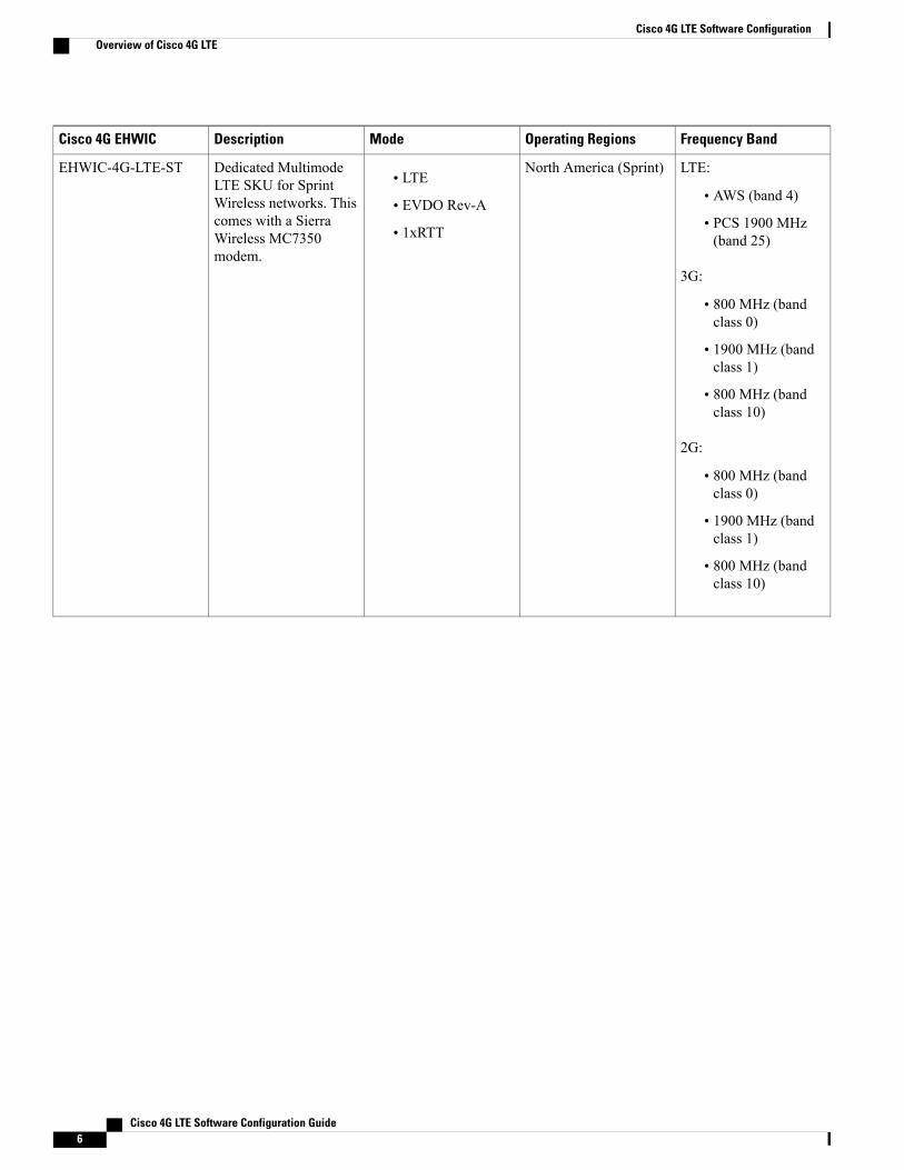
For FDD LTE:
• 700MHz (band 28)
• 850 MHz (band 5)
• 800MHz (band 19)
• 800MHz (band 18)
• 900 MHz (band 8)
• 1800MHz (band 3)
• 2100MHz (band 1)
• 2600MHz (band 7)
For TDD LTE:
• 1900 MHz (Band39)
• 2300 MHz (Band40)
• 2500 MHz (Band41)
• 2600 MHz (Band38)
For UMTS, HSPA+,HSPA:
• 800 MHz (band 6)
• 800MHz (band 19)
• 850 MHz (band 5)
• 900 MHz (band 8)
• 1700MHz (band 9)
• 2100MHz (band 1)
Japan• LTE
• HSPA+
• HSPA
• UMTS
Dedicated MultimodeLTE SKU for Wirelessnetworks in Japan. Thiscomes with a SierraWireless MC7430modem.
EHWIC-LTE-JN
The following table lists the different 4G LTE SKUs available for the Cisco 1110 series routers:
Cisco 4G LTE Software Configuration Guide 13
Cisco 4G LTE Software ConfigurationOverview of Cisco 4G LTE

Table 2: Supported 4G LTE SKUs for Cisco 1110 Series Routers
Frequency BandOperating RegionsModeDescriptionSKU ID
For LTE: 700 MHz(band 13)
For CDMA 1xRTT,1xEVDO Rev A:
• 800 MHz
• 1900 MHz
North AmericaLTE—DOrAC819HG-4G-V-K9 is adedicated MultimodeLTE SKU for VerizonWireless networks andcomes with a SierraWireless MC7750modem.C819HG-4G-V-K9 is ahardened Cisco 819Series Router.
C819HG-4G-V-K9
For LTE: 700 MHz(band 13)
For CDMA 1xRTT,1xEVDO Rev A:
• 800 MHz
• 1900 MHz
North AmericaLTE—DOrAC819G-4G-V-K9 is adedicated MultimodeLTE SKU for VerizonWireless networks andcomes with a SierraWireless MC7750modem.C819G-4G-V-K9 is anon-hardened Cisco 819Series Router.
C819G-4G-V-K9
For LTE:
• 700MHz (band 17)
• AWS (band 4)
• 2100MHz (band 1)
ForUMTS/HSPA+/HSPA:
• 800 MHz
• 850 MHz
• 1900 MHz
• 2100 MHz
For GSM/EDGE/GPRS:
• 850 MHz
• 900 MHz
• 1800 MHz
• 1900 MHz
North AmericaLTE—HSPA+/
HSPA/UMTS/
EDGE/GPRS
C819HG-4G-A-K9 is adedicated MultimodeLTE SKU for AT & TWireless networks andcomes with a SierraWireless MC7700modem.C819HG-4G-A-K9 is ahardened Cisco 819Series Router.
C819HG-4G-A-K9
Cisco 4G LTE Software Configuration Guide14
Cisco 4G LTE Software ConfigurationOverview of Cisco 4G LTE

Frequency BandOperating RegionsModeDescriptionSKU ID
For LTE:
• 700MHz (band 17)
• AWS (band 4)
• 2100MHz (band 1)
ForUMTS/HSPA+/HSPA:
• 800 MHz
• 850 MHz
• 1900 MHz
• 2100 MHz
For GSM/EDGE/GPRS:
• 850 MHz
• 900 MHz
• 1800 MHz
• 1900 MHz
North AmericaLTE—HSPA+/
HSPA/UMTS/
EDGE/GPRS
C819G-4G-A-K9 is adedicated MultimodeLTE SKU for AT&TWireless networks andcomes with a SierraWireless MC7700modem.C819G-4G-A-K9 is acompact non-hardenedCisco 819 Series Router.
C819G-4G-A-K9
For LTE:
• 800MHz (band 20)
• 900 MHz (band 8)
• 1800MHz (band 3)
• 2100MHz (band 1)
• 2600MHz (band 7)
ForUMTS/HSPA+/HSPA:
• 900 MHz
• 2100 MHz
For GSM/EDGE/GPRS:
• 900 MHz
• 1800 MHz
• 1900 MHz
GlobalLTE—HSPA+/
HSPA/UMTS/
EDGE/GPRS
C819HG-4G-G-K9 is adedicated MultimodeLTE SKU for globalwireless networks andcomes with a SierraWireless MC7710modem.C819HG-4G-G-K9 is ahardened Cisco 819Series Router.
C819HG-4G-G-K9
Cisco 4G LTE Software Configuration Guide 15
Cisco 4G LTE Software ConfigurationOverview of Cisco 4G LTE

Frequency BandOperating RegionsModeDescriptionSKU ID
For LTE:
• 800MHz (band 20)
• 900 MHz (band 8)
• 1800MHz (band 3)
• 2100MHz (band 1)
• 2600MHz (band 7)
ForUMTS/HSPA+/HSPA:
• 900 MHz
• 2100 MHz
For GSM/EDGE/GPRS:
• 900 MHz
• 1800 MHz
• 1900 MHz
GlobalLTE—HSPA+/
HSPA/UMTS/
EDGE/GPRS
C819G-4G-G-K9 is adedicated MultimodeLTE SKU for globalwireless networks andcomes with a SierraWireless MC7710modem.C819G-4G-G-K9 is anon-hardened Cisco 819Series Router.
C819G-4G-G-K9
For LTE:
• 800MHz (band 20)
• 900 MHz (band 8)
• 1800MHz (band 3)
• 2100MHz (band 1)
• 2600MHz (band 7)
ForUMTS/HSPA+/HSPA:
• 800 MHz
• 850 MHz
• 1900 MHz
• 2100 MHz
For GSM/EDGE/GPRS:
• 850 MHz
• 900 MHz
• 1800 MHz
• 1900 MHz
Global (Europe,Australia and NewZealand)
LTE—HSPA+/
HSPA/UMTS/
EDGE/GPRS
C819G-4G-GA-K9 is adedicated MultimodeLTE SKU for globalwireless networks andcomes with a SierraWireless MC7304modem.C819G-4G-G-K9 is anon-hardened Cisco 819Series Router.
C819G-4G-GA-K9
Cisco 4G LTE Software Configuration Guide16
Cisco 4G LTE Software ConfigurationOverview of Cisco 4G LTE

Frequency BandOperating RegionsModeDescriptionSKU ID
LTE:
• AWS (band 4)
• 700 MHz (band 5)
• 850MHz (band 17)
• 1900MHz (band 2)
• 2600MHz (band 7)
UMTS, HSPA+, HSPA:
• 1900MHz (band 2)
• AWS (band 4)
• 850 (band 5)
GSM, EDGE, GPRS:
• 850 MHz
• 900 MHz
• 1800 MHz
• 1900 MHz
North America (AT&T,Bell-Canada, Roger,Telus, and otherGSM/LTE operators inUSA and Canada)
• LTE
• HSPA+
• HSPA
• UMTS
• EDGE
• GPRS
Non-hardened Cisco 819router with multi-modeLTE feature for AT & Twireless networks. Thiscomes with a SierraWireless MC7354modem.
C819G-4G-NA-K9
Cisco 4G LTE Software Configuration Guide 17
Cisco 4G LTE Software ConfigurationOverview of Cisco 4G LTE

Frequency BandOperating RegionsModeDescriptionSKU ID
LTE:
• AWS (band 4)
• 700MHz (band 13)
• PCS 1900 MHz(band 25)
3G:
• 800 MHz (bandclass 0)
• 1900 MHz (bandclass 1)
• 800 MHz (bandclass 10)
2G:
• 800 MHz (bandclass 0)
• 1900 MHz (bandclass 1)
• 800 MHz (bandclass 10)
North America (Sprint)• LTE
• EVDO Rev-A
• 1xRTT
Non-hardened Cisco 819router with multi-modeLTE feature for Sprintwireless networks. Thiscomes with a SierraWireless MC7350modem.
C819G-4G-ST-K9
Cisco 4G LTE Software Configuration Guide18
Cisco 4G LTE Software ConfigurationOverview of Cisco 4G LTE

Frequency BandOperating RegionsModeDescriptionSKU ID
LTE:
• AWS (band 4)
• 700MHz (band 13)
• PCS 1900 MHz(band 25)
3G:
• 800 MHz (bandclass 0)
• 1900 MHz (bandclass 1)
• 800 MHz (bandclass 10)
2G:
• 800 MHz (bandclass 0)
• 1900 MHz (bandclass 1)
• 800 MHz (bandclass 10)
North America (Verizon)• LTE
• EVDO Rev-A
• 1xRTT
Non-hardened Cisco 819router with multi-modeLTE feature for Verizonwireless networks. Thiscomes with a SierraWireless MC7350modem.
C819G-4G-VZ-K9
Cisco 4G LTE Software Configuration Guide 19
Cisco 4G LTE Software ConfigurationOverview of Cisco 4G LTE
Frequency BandOperating RegionsModeDescriptionSKU ID
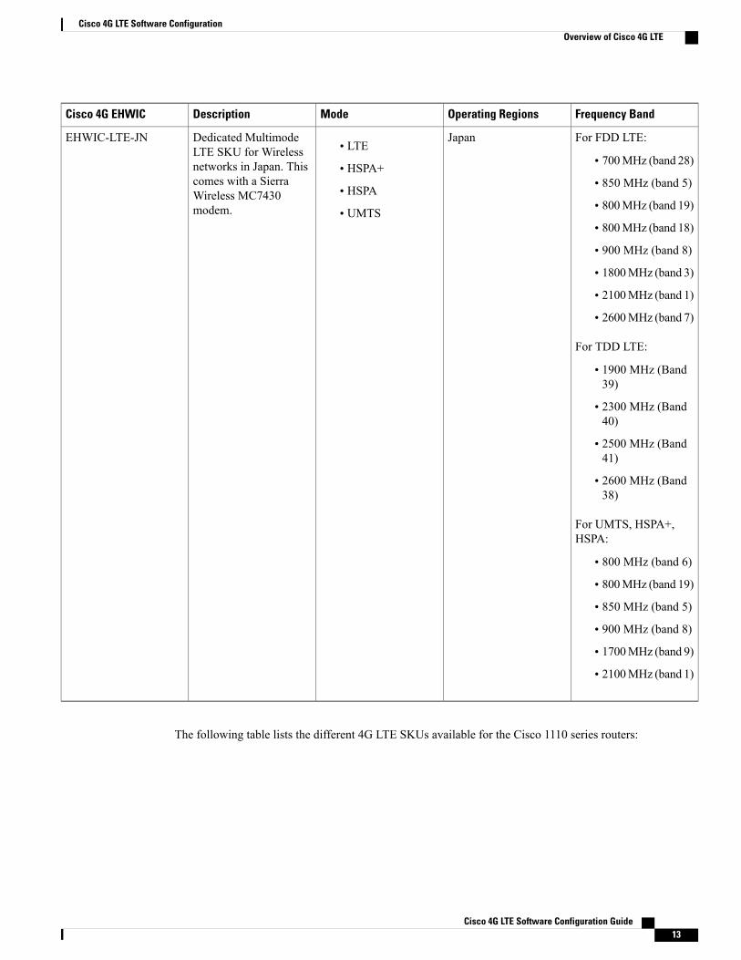
For LTE:
• 700 MHz (Band13)
• 700 MHz (Band17)
• 800 MHz (Band 5)
• 1900 MHz (Band2)
• 1900 MHz (Band25)
• AWS 1700/2100MHz (Band 4)
For HSPA+:
• 850 MHz (Band 5)
• 900 MHz (Band 8)
• 1900 MHz (Band2)
• 2100 MHz (Band1)
• AWS 1700/2100MHz (Band 4)
For CDMA and EVDORevision A:
• 800 MHz (BandClass 0)
• 1900 MHz (BandClass 1)
• 800 MHz (BandClass 10)
For EDGE/GPRS/GSM:
• 850 MHz
• 900 MHz
• 1800 MHz
• 1900 MHz
North America• LTE
• HSPA+
• EVDO Revision A(DOrA)
• CDMA
• EDGE/GPRS/GSM
C819GW-LTE-MNA-AK9is a dedicatedMultimodeLTE SKU for NorthAmerica wirelessnetworks and comeswitha Sierra WirelessMC7354MNA modem.
C819GW-LTE-MNA-AK9is a non-hardened Cisco819 Series Router.
For 3GPP complaint, theextended temperaturerange for this SKU is -15to 50C. For non-3GPPcomplaint, it is -15 to55C.
Dual SIMs in this SKUprovide high reliabilityand cellular multihomingsupport for LTE andHSPA-based networksusing the common FWtechnology within thesame region. Dual SIMsin the North AmericanSKUs provideswitchover with differentFW technology.
This is a 4G+WIFI SKU. ThisSKU supportsall NorthAmericancarriers likeVerizon, ATT,Sprint, andCanada usingMC7354MNAmodems.
Note
C819GW-LTE-MNA-AK9
Cisco 4G LTE Software Configuration Guide20
Cisco 4G LTE Software ConfigurationOverview of Cisco 4G LTE

Frequency BandOperating RegionsModeDescriptionSKU ID
For LTE:
• 800 MHz (Band20)
• 900 MHz (Band 8)
• 1800 MHz (Band3)
• 2100 MHz (Band1)
• 2600 MHz (Band7)
For HSPA+:
• 850 MHz (Band 5)
• 900 MHz (Band 8)
• 1900 MHz (Band2)
• 2100 MHz (Band1)
For EDGE/GPRS/GSM:
• 850 MHz
• 900 MHz
• 1800 MHz
• 1900 MHz
Global (Europe andAustralia)• LTE
• HSPA+
• EDGE/GPRS/GSM
C819GW-LTE-GA-EK9is a dedicatedMultimodeLTE SKU for globalwireless network andcomes with a SierraWireless MC7304modem.
C819GW-LTE-GA-EK9is a non-hardened Cisco819 Series Router.
For 3GPP complaint, theextended temperaturerange for this SKU is -15to 50C. For non-3GPPcomplaint, it is -15 to55C.
Dual SIMs in this SKUprovide high reliabilityand cellular multihomingsupport for LTE andHSPA-based networksusing the common FWtechnology within thesame region. Dual SIMsprovide switchover withdifferent FW technology.
This is a 4G +WIFI SKU forGlobal andAustraliamarket.
Note
C819GW-LTE-GA-EK9
Cisco 4G LTE Software Configuration Guide 21
Cisco 4G LTE Software ConfigurationOverview of Cisco 4G LTE

Frequency BandOperating RegionsModeDescriptionSKU ID
LTE:
• 850Mhz(band 19)
• 1500Mhz(band 21)
• 2100Mhz(band 1)
3G(UMTS,HSPA+,HSPA):
• 800Mhz(band 6)
• 850Mhz(band 5)
• 850Mhz(band 19)
• 2100Mhz(band 1)
2G(GSM,EDGE,GPRS):
• 850Mhz
• 900Mhz
• 1800Mhz
• 1900Mhz
Global (Europe andAustralia)• LTE
• HSPA+
• EDGE/GPRS/GSM
• CDMA
• EVDO
C819G-LTE-MNA-K9is a dedicatedMultimodeLTE SKU for globalwireless network andcomes with a SierraWirelessMC7354-MNAmodem.
C819G-LTE-MNA-K9is a non-hardened Cisco819 Series Router.
For 3GPP complaint, theextended temperaturerange for this SKU is -15to 50C. For non-3GPPcomplaint, it is -15 to55C.
Dual SIMs in this SKUprovide high reliabilityand cellular multihomingsupport for LTE andHSPA-based networksusing the common FWtechnology within thesame region. Dual SIMsprovide switchover withdifferent FW technology.
This SKU doesnot have a WiFimodule.
Note
C819G-LTE-MNA-K9
Cisco 4G LTE Software Configuration Guide22
Cisco 4G LTE Software ConfigurationOverview of Cisco 4G LTE

Frequency BandOperating RegionsModeDescriptionSKU ID
For FDD LTE:
• 700MHz (band 28)
• 850 MHz (band 5)
• 800MHz (band 19)
• 800MHz (band 18)
• 900 MHz (band 8)
• 1800MHz (band 3)
• 2100MHz (band 1)
• 2600MHz (band 7)
For TDD LTE:
• 1900 MHz (Band39)
• 2300 MHz (Band40)
• 2500 MHz (Band41)
• 2600 MHz (Band38)
For UMTS, HSPA+,HSPA:
• 800 MHz (band 6)
• 800MHz (band 19)
• 850 MHz (band 5)
• 900 MHz (band 8)
• 1700MHz (band 9)
• 2100MHz (band 1)
Latin America/APAC• LTE
• HSPA+
• HSPA
• UMTS
C819G-LTE-LA-K9 is adedicated MultimodeLTE SKU for LatinAmerican wirelessnetworks and comeswitha Sierra WirelessMC7430 modem.
C819G-LTE-LA-K9
Cisco 4G LTE Software Configuration Guide 23
Cisco 4G LTE Software ConfigurationOverview of Cisco 4G LTE

Frequency BandOperating RegionsModeDescriptionSKU ID
For FDD LTE:
• 700MHz (band 28)
• 850 MHz (band 5)
• 800MHz (band 19)
• 800MHz (band 18)
• 900 MHz (band 8)
• 1800MHz (band 3)
• 2100MHz (band 1)
• 2600MHz (band 7)
For TDD LTE:
• 1900 MHz (Band39)
• 2300 MHz (Band40)
• 2500 MHz (Band41)
• 2600 MHz (Band38)
For UMTS, HSPA+,HSPA:
• 800 MHz (band 6)
• 800MHz (band 19)
• 850 MHz (band 5)
• 900 MHz (band 8)
• 1700MHz (band 9)
• 2100MHz (band 1)
Latin America/APAC• LTE
• HSPA+
• HSPA
• UMTS
C819G-LTE-LA-K9 is adedicated MultimodeLTE SKU for LatinAmerican wirelessnetworks and comeswitha Sierra WirelessMC7430 modem.
C819GW-LTE-LA-CK9
Cisco 4G LTE Software Configuration Guide24
Cisco 4G LTE Software ConfigurationOverview of Cisco 4G LTE

Frequency BandOperating RegionsModeDescriptionSKU ID
For FDD LTE:
• 700MHz (band 28)
• 850 MHz (band 5)
• 800MHz (band 19)
• 800MHz (band 18)
• 900 MHz (band 8)
• 1800MHz (band 3)
• 2100MHz (band 1)
• 2600MHz (band 7)
For TDD LTE:
• 1900 MHz (Band39)
• 2300 MHz (Band40)
• 2500 MHz (Band41)
• 2600 MHz (Band38)
For UMTS, HSPA+,HSPA:
• 800 MHz (band 6)
• 800MHz (band 19)
• 850 MHz (band 5)
• 900 MHz (band 8)
• 1700MHz (band 9)
• 2100MHz (band 1)
Latin America/APAC• LTE
• HSPA+
• HSPA
• UMTS
C819G-LTE-LA-QK9 isa dedicated MultimodeLTE SKU for LatinAmerican wirelessnetworks and comeswitha Sierra WirelessMC7430 modem.
C819GW-LTE-LA-QK9
Cisco 4G LTE Software Configuration Guide 25
Cisco 4G LTE Software ConfigurationOverview of Cisco 4G LTE

Frequency BandOperating RegionsModeDescriptionSKU ID
For FDD LTE:
• 700MHz (band 28)
• 850 MHz (band 5)
• 800MHz (band 19)
• 800MHz (band 18)
• 900 MHz (band 8)
• 1800MHz (band 3)
• 2100MHz (band 1)
• 2600MHz (band 7)
For TDD LTE:
• 1900 MHz (Band39)
• 2300 MHz (Band40)
• 2500 MHz (Band41)
• 2600 MHz (Band38)
For UMTS, HSPA+,HSPA:
• 800 MHz (band 6)
• 800MHz (band 19)
• 850 MHz (band 5)
• 900 MHz (band 8)
• 1700MHz (band 9)
• 2100MHz (band 1)
Latin America/APAC• LTE
• HSPA+
• HSPA
• UMTS
C819G-LTE-LA-NK9 isa dedicated MultimodeLTE SKU for LatinAmerican wirelessnetworks and comeswitha Sierra WirelessMC7430 modem.
C819GW-LTE-LA-NK9
The following table lists the different 4G LTE SKUs available for the Cisco 880 and Cisco 890 series ISRs.
Cisco 4G LTE Software Configuration Guide26
Cisco 4G LTE Software ConfigurationOverview of Cisco 4G LTE

Table 3: Supported 4G LTE SKUs for the Cisco 880 and Cisco 890 Series ISRs
DescriptionFrequency BandOperating RegionModeSKU ID
Cisco 880 Series ISRwith Multimode LTEfeature for globalwireless networks.C881G-4G-GA-K9comes with a SierraWireless MC7304modem.
LTE:
• 800MHz (band 20)
• 900 MHz (band 8)
• 1800MHz (band 3)
• 2100MHz (band 1)
• 2600MHz (band 7)
3G (UMTS, HSPA+,HSPA):
• 800 MHz (band 6)
• 850 MHz (band 5)
• 900 MHz (band 8)
• 1900MHz (band 2)
• 2100MHz (band 1)
2G (GSM, EDGE,GPRS):
• 850 MHz
• 900 MHz
• 1800 MHz
• 1900 MHz
Global (Europe, NewZealand, and Australia)• LTE
• HSPA+
• HSPA
• UMTS
• EDGE
• GPRS
C881G-4G-GA-K9
Cisco 4G LTE Software Configuration Guide 27
Cisco 4G LTE Software ConfigurationOverview of Cisco 4G LTE

DescriptionFrequency BandOperating RegionModeSKU ID
Cisco 880 series ISRwith Multimode LTEfeature for globalwireless networks.C887VAG-4G-GA-K9comes with a SierraWireless MC7304modem.
LTE:
• 800MHz (band 20)
• 900 MHz (band 8)
• 1800MHz (band 3)
• 2100MHz (band 1)
• 2600MHz (band 7)
3G (UMTS, HSPA+,HSPA):
• 800 MHz (band 6)
• 850 MHz (band 5)
• 900 MHz (band 8)
• 1900MHz (band 2)
• 2100MHz (band 1)
2G (GSM, EDGE,GPRS):
• 850 MHz
• 900 MHz
• 1800 MHz
• 1900 MHz
Global (Europe, NewZealand, and Australia)• LTE
• HSPA+
• HSPA
• UMTS
• EDGE
• GPRS
C887VAG-4G-GA-K9
Cisco 4G LTE Software Configuration Guide28
Cisco 4G LTE Software ConfigurationOverview of Cisco 4G LTE

DescriptionFrequency BandOperating RegionModeSKU ID
Cisco 890 series ISRwith Multimode LTEfeature for globalwireless networks.C896VAG-LTE-GA-K9comes with a SierraWireless MC7304modem.
LTE:
• 800MHz (band 20)
• 900 MHz (band 8)
• 1800MHz (band 3)
• 2100MHz (band 1)
• 2600MHz (band 7)
3G (UMTS, HSPA+,HSPA):
• 800 MHz (band 6)
• 850 MHz (band 5)
• 900 MHz (band 8)
• 1900MHz (band 2)
• 2100MHz (band 1)
2G (GSM, EDGE,GPRS):
• 850 MHz
• 900 MHz
• 1800 MHz
• 1900 MHz
Global (Europe, NewZealand, and Australia)• LTE
• HSPA+
• HSPA
• UMTS
• EDGE
• GPRS
C896VAG-LTE-GA-K9
Cisco 4G LTE Software Configuration Guide 29
Cisco 4G LTE Software ConfigurationOverview of Cisco 4G LTE

DescriptionFrequency BandOperating RegionModeSKU ID
Cisco 890 series ISRwith Multimode LTEfeature for globalwireless networks.C897VAG-LTE-GA-K9comes with a SierraWireless MC7304modem.
LTE:
• 800MHz (band 20)
• 900 MHz (band 8)
• 1800MHz (band 3)
• 2100MHz (band 1)
• 2600MHz (band 7)
3G (UMTS, HSPA+,HSPA):
• 800 MHz (band 6)
• 850 MHz (band 5)
• 900 MHz (band 8)
• 1900MHz (band 2)
• 2100MHz (band 1)
2G (GSM, EDGE,GPRS):
• 850 MHz
• 900 MHz
• 1800 MHz
• 1900 MHz
Global (Europe, NewZealand, and Australia)• LTE
• HSPA+
• HSPA
• UMTS
• EDGE
• GPRS
C897VAG-LTE-GA-K9
Cisco 4G LTE Software Configuration Guide30
Cisco 4G LTE Software ConfigurationOverview of Cisco 4G LTE

DescriptionFrequency BandOperating RegionModeSKU ID
Cisco 890 series ISRwith Multimode LTEfeature for globalwireless networks.C897VAMG-LTE-GA-K9comes with a SierraWireless MC7304modem.
LTE:
• 800MHz (band 20)
• 900 MHz (band 8)
• 1800MHz (band 3)
• 2100MHz (band 1)
• 2600MHz (band 7)
3G (UMTS, HSPA+,HSPA):
• 800 MHz (band 6)
• 850 MHz (band 5)
• 900 MHz (band 8)
• 1900MHz (band 2)
• 2100MHz (band 1)
2G (GSM, EDGE,GPRS):
• 850 MHz
• 900 MHz
• 1800 MHz
• 1900 MHz
Global (Europe, NewZealand, and Australia)• LTE
• HSPA+
• HSPA
• UMTS
• EDGE
• GPRS
C897VAMG-LTE-GA-K9
Cisco 4G LTE Software Configuration Guide 31
Cisco 4G LTE Software ConfigurationOverview of Cisco 4G LTE

DescriptionFrequency BandOperating RegionModeSKU ID
Cisco 890 series ISRwith Multimode LTEfeature for globalwireless networks.C898EAG-LTE-GA-K9comes with a SierraWireless MC7304modem.
LTE:
• 800MHz (band 20)
• 900 MHz (band 8)
• 1800MHz (band 3)
• 2100MHz (band 1)
• 2600MHz (band 7)
3G (UMTS, HSPA+,HSPA):
• 800 MHz (band 6)
• 850 MHz (band 5)
• 900 MHz (band 8)
• 1900MHz (band 2)
• 2100MHz (band 1)
2G (GSM, EDGE,GPRS):
• 850 MHz
• 900 MHz
• 1800 MHz
• 1900 MHz
Global (Europe, NewZealand, and Australia)• LTE
• HSPA+
• HSPA
• UMTS
• EDGE
• GPRS
C898EAG-LTE-GA-K9
Cisco 4G LTE Software Configuration Guide32
Cisco 4G LTE Software ConfigurationOverview of Cisco 4G LTE

DescriptionFrequency BandOperating RegionModeSKU ID
Cisco 890 series ISRwith Multimode LTEfeature for globalWireless networks.C899G-LTE-GA-K9comes with a SierraWireless MC7304modem.
LTE:
• 800MHz (band 20)
• 900 MHz (band 8)
• 1800MHz (band 3)
• 2100MHz (band 1)
• 2600MHz (band 7)
3G (UMTS, HSPA+,HSPA):
• 800 MHz (band 6)
• 850 MHz (band 5)
• 900 MHz (band 8)
• 1900MHz (band 2)
• 2100MHz (band 1)
2G (GSM, EDGE,GPRS):
• 850 MHz
• 900 MHz
• 1800 MHz
• 1900 MHz
Global (Europe, NewZealand, and Australia)• LTE
• HSPA+
• HSPA
• UMTS
• EDGE
• GPRS
C899G-LTE-GA-K9
Cisco 4G LTE Software Configuration Guide 33
Cisco 4G LTE Software ConfigurationOverview of Cisco 4G LTE

DescriptionFrequency BandOperating RegionModeSKU ID
Cisco 890 series ISRwith Multimode LTEfeature for Verizonwireless networks.C899G-LTE-VZ-K9comes with a SierraWireless MC7350modem.
LTE:
• AWS (band 4)
• 700MHz (band 13)
• PCS 1900 MHz(band 25)
3G:
• 800 MHz (bandclass 0)
• 1900 MHz (bandclass 1)
• 800 MHz (bandclass 10)
2G:
• 800 MHz (bandclass 0)
• 1900 MHz (bandclass 1)
• 800 MHz (bandclass 10)
North America (Verizon)• LTE
• EVDO Rev-A
• 1xRTT
C899G-LTE-VZ-K9
Cisco 4G LTE Software Configuration Guide34
Cisco 4G LTE Software ConfigurationOverview of Cisco 4G LTE

DescriptionFrequency BandOperating RegionModeSKU ID
Cisco 890 series ISRwith Multimode LTEfeature for wirelessnetworks in USA andCanada.C899G-LTE-NA-K9comes with a SierraWireless MC7354modem.
LTE:
• AWS (band 4)
• 700 MHz (band 5)
• 850MHz (band 17)
• 1900MHz (band 2)
• 2600MHz (band 7)
3G (UMTS, HSPA+,HSPA):
• 1900MHz (band 2)
• AWS (band 4)
• 850 (band 5)
2G (GSM, EDGE,GPRS):
• 850 MHz
• 900 MHz
• 1800 MHz
• 1900 MHz
North America (AT&T,Bell-Canada, Roger,Telus, and otherGSM/LTE operators inUSA and Canada)
• LTE
• HSPA+
• HSPA
• UMTS
• EDGE
• GPRS
C899G-LTE-NA-K9
Cisco 4G LTE Software Configuration Guide 35
Cisco 4G LTE Software ConfigurationOverview of Cisco 4G LTE

DescriptionFrequency BandOperating RegionModeSKU ID
Cisco 890 series ISRwith Multimode LTEfeature for Sprintwireless networks.C899G-LTE-ST-K9comes with a SierraWireless MC7350modem.
LTE:
• AWS (band 4)
• 700MHz (band 13)
• PCS 1900 MHz(band 25)
3G:
• 800 MHz (bandclass 0)
• 1900 MHz (bandclass 1)
• 800 MHz (bandclass 10)
2G:
• 800 MHz (bandclass 0)
• 1900 MHz (bandclass 1)
• 800 MHz (bandclass 10)
North America (Sprint)• LTE
• EVDO Rev-A
• 1xRTT
C899G-LTE-ST-K9
Cisco 4G LTE Software Configuration Guide36
Cisco 4G LTE Software ConfigurationOverview of Cisco 4G LTE

DescriptionFrequency BandOperating RegionModeSKU ID
Cisco 890 series ISRwith Multimode LTEfeature for globalwireless networks.C899G-LTE-JP-K9comes with a SierraWireless MC7330modem.
LTE:
• 800MHz (band 20)
• 850MHz (band 19)
• 900 MHz (band 8)
• 1500 MHz (band21)
• 1800MHz (band 3)
• 2100MHz (band 1)
• 2600MHz (band 7)
3G (UMTS, HSPA+,HSPA):
• 800 MHz (band 6)
• 850 MHz (band 5)
• 900 MHz (band 8)
• 1900MHz (band 2)
• 2100MHz (band 1)
2G (GSM, EDGE,GPRS):
• 850 MHz
• 900 MHz
• 1800 MHz
• 1900 MHz
Global (Japan)• LTE
• HSPA+
• HSPA
• UMTS
• EDGE
• GPRS
C899G-LTE-JP-K9
Cisco 4G LTE Software Configuration Guide 37
Cisco 4G LTE Software ConfigurationOverview of Cisco 4G LTE

DescriptionFrequency BandOperating RegionModeSKU ID
For FDD LTE:
• 700MHz (band 28)
• 850 MHz (band 5)
• 800MHz (band 19)
• 800MHz (band 18)
• 900 MHz (band 8)
• 1800MHz (band 3)
• 2100MHz (band 1)
• 2600MHz (band 7)
For TDD LTE:
• 1900 MHz (Band39)
• 2300 MHz (Band40)
• 2500 MHz (Band41)
• 2600 MHz (Band38)
For UMTS, HSPA+,HSPA:
• 800 MHz (band 6)
• 800MHz (band 19)
• 850 MHz (band 5)
• 900 MHz (band 8)
• 1700MHz (band 9)
• 2100MHz (band 1)
Latin America• LTE
• HSPA+
• HSPA
• UMTS
C897VAG-LTE-LA-K9is a dedicatedMultimodeLTE SKU for LatinAmerican wirelessnetworks and comeswitha Sierra WirelessMC7430 modem.
C897VAG-LTE-LA-K9
Cisco 4G LTE Software Configuration Guide38
Cisco 4G LTE Software ConfigurationOverview of Cisco 4G LTE

DescriptionFrequency BandOperating RegionModeSKU ID
For FDD LTE:
• 700MHz (band 28)
• 850 MHz (band 5)
• 800MHz (band 19)
• 800MHz (band 18)
• 900 MHz (band 8)
• 1800MHz (band 3)
• 2100MHz (band 1)
• 2600MHz (band 7)
For TDD LTE:
• 1900 MHz (Band39)
• 2300 MHz (Band40)
• 2500 MHz (Band41)
• 2600 MHz (Band38)
For UMTS, HSPA+,HSPA:
• 800 MHz (band 6)
• 800MHz (band 19)
• 850 MHz (band 5)
• 900 MHz (band 8)
• 1700MHz (band 9)
• 2100MHz (band 1)
ASEAN• LTE
• HSPA+
• HSPA
• UMTS
C898EAG-LTE-LA-K9is a dedicatedMultimodeLTE SKU for ASEANwireless networks andcomes with a SierraWireless MC7430modem.
C898EAG-LTE-LA-K9
Cisco 4G LTE Software Configuration Guide 39
Cisco 4G LTE Software ConfigurationOverview of Cisco 4G LTE

DescriptionFrequency BandOperating RegionModeSKU ID
For FDD LTE:
• 700MHz (band 28)
• 850 MHz (band 5)
• 800MHz (band 19)
• 800MHz (band 18)
• 900 MHz (band 8)
• 1800MHz (band 3)
• 2100MHz (band 1)
• 2600MHz (band 7)
For TDD LTE:
• 1900 MHz (Band39)
• 2300 MHz (Band40)
• 2500 MHz (Band41)
• 2600 MHz (Band38)
Latin America andAPAC• LTE
• HSPA+
• HSPA
• UMTS
C899G-LTE-LA-K9 is adedicated MultimodeLTE SKU for LatinAmerican wirelessnetworks and comeswitha Sierra WirelessMC7430 modem.
C899G-LTE-LA-K9
Cisco 4G LTE Software Configuration Guide40
Cisco 4G LTE Software ConfigurationOverview of Cisco 4G LTE

The following figure explains the 4G LTE packet core network architecture.
Figure 1: 4G LTE Packet Core Network Architecture
The Serving Gateway (SGW) routes and forwardsuser data packets, while also acting as the mobilityanchor for the user plane, and is the anchor formobility between LTE and other 3GPP technologies.The Packet Data Network (PDN) Gateway (PGW)provides connectivity from the User Equipment (UE)to external packet data networks by being the pointof exit and entry of traffic for the UE.
AUEmay have simultaneous connectivity with morethan one PGW for accessing multiple PDNs. ThePGW performs policy enforcement, packet filteringfor each user, charging support, lawful interception,and packet screening. Another key role of the PGWis to act as the anchor for mobility between 3GPP andnon-3GPP technologies such asWiMAX and 3GPP2(CDMA 1X and EvDO).
The System Architecture Evolution GW (SAE GW)is the entity that covers the PGW and SGWfunctionality in the Evolved Packet Core (EPC).
Gateways
Cisco 4G LTE Software Configuration Guide 41
Cisco 4G LTE Software ConfigurationOverview of Cisco 4G LTE

The Radio Network Controller (RNC) is responsiblefor controlling the Radio Access Network (RAN) thatare connected to it. The RNC carries out radioresource management and some of the mobilitymanagement functions and is the point whereencryption is done before user data is sent to and fromthe mobile. The RNC connects to theCircuit-Switched Core Network through the MediaGateway (MGW).
RNC
Base Transceiver Station.BTS
Base Station Controller.BSC
Service GPRS Support Node.SGSN
Cisco 4G LTE FeaturesCisco 4G LTE WWAN EHWICs, Cisco 1110 Series 4G LTE routers support the following major features:
• Global Positioning System (GPS) and National Marine Electronics Association (NMEA) streaming.
• 4G Short Message Service (SMS)
• 3G/4G Simple Network Management Protocol (SNMP) MIB
• Auto-switch failover between primary and backup link
• Multichannel-interface-processor (MIP) profile configuration
• Remotely initiated data callback using voice
• Remotely initiated data callback using Short Message Service (SMS)
• Remote firmware upgrade over 4G LTE
• Virtual diagnostic monitoring
• Mobile Equipment Personalization (MEP) lock and unlock capabilities
• SIM lock and unlock capabilities
• Multiple PDN Contexts
• Quality of Service
4G GPS and NMEA
The Global Positioning System (GPS) feature is enabled by default on the supported Cisco 1110 Series routersand Cisco 4G LTE EHWICs to provide the geographical location.
Active GPS is supported on the SubMiniature version A (SMA) port. Active GPS antenna is supported onlyin the standalone mode. An Active GPS antenna includes a built-in Low-Noise Amplifier that providessufficient gain to overcome coaxial cable losses while providing the proper signal level to the GPS receiver.
Cisco 4G LTE Software Configuration Guide42
Cisco 4G LTE Software ConfigurationCisco 4G LTE Features

ActiveGPS antennae require power from theGPS receiver SMAport to operate. See the Example: Connectingto a Server Hosting a GPS Application section for more information.
National Marine Electronics Association (NMEA) streams GPS data either from a 4G EHWIC or a Cisco1110 series router through a virtual COM port and a TCP/IP Ethernet connection to any marine device (suchas a Windows-based PC) that runs a commercially available GPS-based application.
The following GPS and NMEA features are supported on the Cisco 1110 series routers:
• GPS standalone mode (satellite-based GPS).
• Cisco IOS CLI display coordinates.
• Virtual and physical serial ports can export NMEA-formatted GPS data.
• External application displays router map location.
• Objects in the CISCO-WAN-3G-MIB supports GPS and NMEA features.
• The Cisco 4G LTE EHWIC supports only the IP NMEA streaming option.
• The Cisco 1110 series routers can support either IP or serial NMEA streaming options.
Assisted GPS mode is not supported.Note
For instructions on setting up the GPS antenna, see the Cisco 4G Indoor/Outdoor Active GPS Antenna(GPS-ACT-ANTM-SMA) document.
Connecting to a Server Hosting a GPS Application
You can feed the NMEA data to a remote server that hosts the GPS application. The server can be connectedto the router either directly using an Ethernet cable or through a LAN or WAN network. If the applicationsupports serial port, run a serial port emulation program to create a virtual serial port over the LAN or WANconnection.
Microsoft Streets & Trips is a licensed software that you can download from the Microsoft website.Note
To connect a Cisco 1110 series router through IP to a PC running Microsoft Streets & Trips, perform thefollowing steps:
1 Connect the PC to the router using an Ethernet cable.2 Ensure that the PC and router can ping.3 Launch the serial port redirector on the PC.4 Use the show line command in the privileged EXEC mode to locate the NMEA port on the router.5 Create a virtual serial port that connects to the NMEA port on the router.6 LaunchMicrosoft Streets & Trips on your PC.7 Select the GPS Menu.8 Click Start Tracking.9 If you have acquired a location fix from the show cellular gps command output on the router, the current
location is plotted on the graph, and a reddish brown dotted cursor with a circle around it is seen on themap.
Cisco 4G LTE Software Configuration Guide 43
Cisco 4G LTE Software ConfigurationCisco 4G LTE Features
If you have not acquired a location fix, the Microsoft application times out and disconnects.Note
Short Message Service (SMS) Capabilities
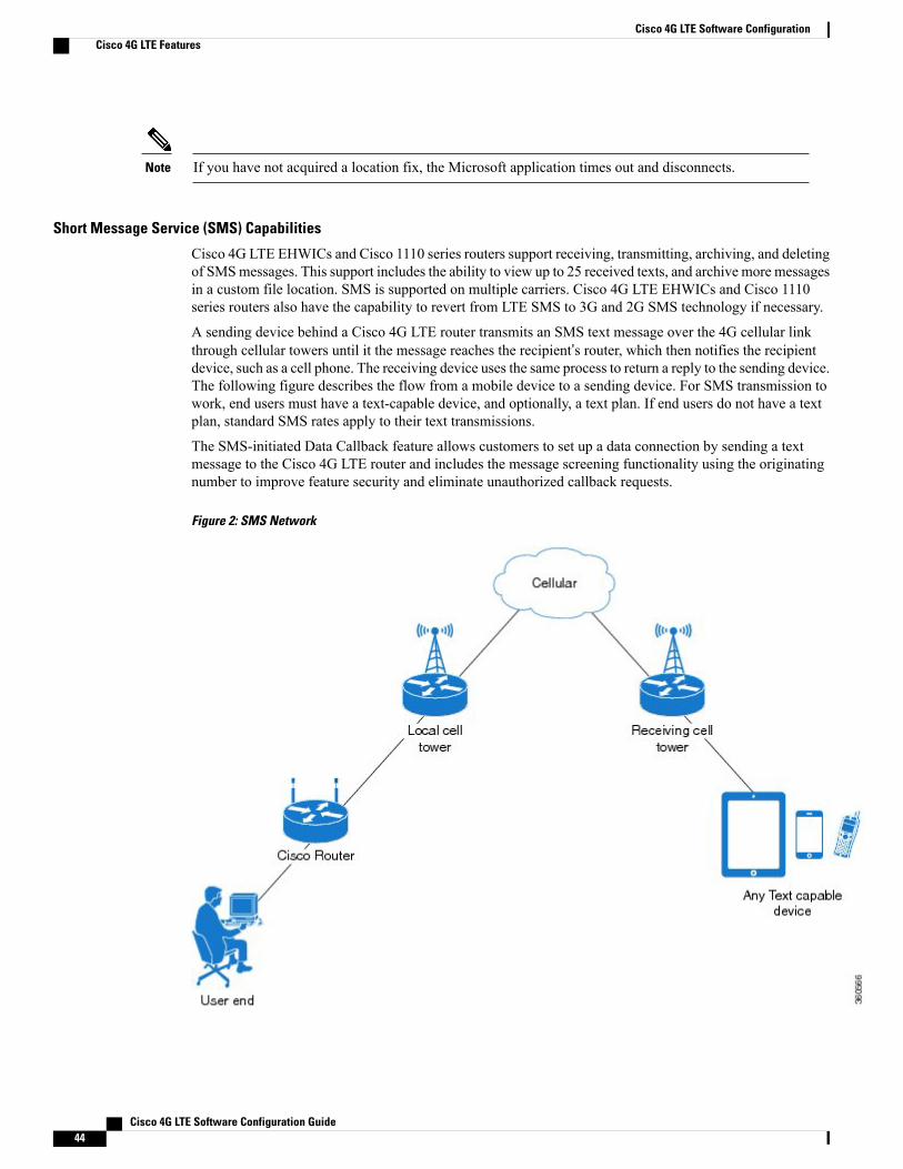
Cisco 4G LTE EHWICs and Cisco 1110 series routers support receiving, transmitting, archiving, and deletingof SMSmessages. This support includes the ability to view up to 25 received texts, and archive more messagesin a custom file location. SMS is supported on multiple carriers. Cisco 4G LTE EHWICs and Cisco 1110series routers also have the capability to revert from LTE SMS to 3G and 2G SMS technology if necessary.
A sending device behind a Cisco 4G LTE router transmits an SMS text message over the 4G cellular linkthrough cellular towers until it the message reaches the recipient’s router, which then notifies the recipientdevice, such as a cell phone. The receiving device uses the same process to return a reply to the sending device.The following figure describes the flow from a mobile device to a sending device. For SMS transmission towork, end users must have a text-capable device, and optionally, a text plan. If end users do not have a textplan, standard SMS rates apply to their text transmissions.
The SMS-initiated Data Callback feature allows customers to set up a data connection by sending a textmessage to the Cisco 4G LTE router and includes the message screening functionality using the originatingnumber to improve feature security and eliminate unauthorized callback requests.
Figure 2: SMS Network
Cisco 4G LTE Software Configuration Guide44
Cisco 4G LTE Software ConfigurationCisco 4G LTE Features

Using a SIM Card
Cisco 4G LTE EHWICs and Cisco 1110 series routers need an active SIM card provided by a service provider.The SIM cards are usually provided in an unlocked state so that it can be used without a Personal IdentificationNumber (PIN). If the SIM is unlocked, it can be inserted into an EHWIC and used without an authorizationcode.
The SIM can be initially locked with a PIN code (4 to 8 digits s long) defined by the service provider. Contactyour service provider for the PIN code.
The SIM-Lock feature allows a SIM to be locked or unlocked with a PIN code so that it is used only in anauthorized device. Perform the SIM lock and unlock procedures using the Cisco IOS CLI through a consoleor Telnet/SSH to the router.
After the SIM is locked, it cannot initiate a call unless authentication is done using the same PIN. Authenticationis done automatically by Cisco IOS through configuration of the PIN. This mandatory configuration forautomatic SIM authentication is done using the Cisco IOS CLI as part of the router startup configuration.
After the Cisco IOS configuration is in place, the router can initiate an LTE connection. The router uses theconfigured PIN to authenticate prior to the LTE connection. If the Cisco IOS PIN configuration is missing orif the PIN is incorrect, the SIM authentication will fail and the connection will not be initiated.
If the locked SIM is moved to a different router or to another device, or if the EHWIC in which the lockedSIM resides is moved to a different EHWIC slot in the same router, the router configuration should be changed.The configuration is associated with the cellular controller that is specific to a router EHWIC slot number.This will ensure that the SIM card will not be used in any unauthorized device, or, if there are multiple LTEEHWICs in a single ISR, that the appropriate PIN is applied to each LTE EHWIC/SIM. An authenticationcommand (with the same PIN used to lock the SIM) must be defined on the new device or on the new cellularcontroller slot to successfully initiate the LTE connection.
It is very important to use the correct PIN after it is configured. The SIM card will be blocked if the wrongPIN is entered three consecutive times on a locked SIM during authentication or when trying to unlock alocked SIM. You can unblock a blocked SIM card using the PUK code. Contact your service provider forthe PUK code. Use the cellular slot lte sim unblock PUK-code new-PIN-code command to unblock theSIM.
Note
The following procedures are used to configure a SIM:
Data Account Provisioning
One or more modem data profiles can be created to provision a modem on a 3G or 4G EHWIC. An activewireless account with a service provider with one or more (dual) SIM cards must be installed. The modemdata profile is preconfigured on the modem.
The following tasks are used to verify the signal strength and service availability of the modem and to create,modify, and delete modem data profiles:
IP Multimedia Subsystem Profiles
IP Multimedia Subsystem (IMS) profiles establish a session, and are a part of the modem configuration andare stored in the modem's NVRAM. An IMS network is an access-independent and standard-based IPconnectivity service that enables different types of multimedia services to end users using common
Cisco 4G LTE Software Configuration Guide 45
Cisco 4G LTE Software ConfigurationCisco 4G LTE Features

Internet-based protocols. See Creating, Modifying, or Deleting Modem Data Profiles, on page 62, for moreinformation.
Usage Guidelines for Creating, Modifying, or Deleting Data Profiles
You can create multiple profiles on Cisco 4G LTE EHWICs and Cisco 1110 series routers. The following arethe default Internet profile numbers for some of the modems:
• MC7700—Profile 1
• MC7710—Profile 1
• MC7750—Profile 3
• MC7304—Profile 1
• MC7350—Profile 3
• MC7354—Profile 1
• MC7430—Profile 1
For information on supported modems on each SKU, see the tables in the Overview of Cisco 4G LTE, onpage 2.
The maximum number of profiles that can be created for each modem is given as follows:
• MC7700—Up to 16 profiles
• MC 7710—Up to 16 profiles
• MC7750—Up to 6 profiles
• MC7304—Up to 16 profiles
• MC7350—Up to 6 profiles
• MC7354—Up to 16 profiles
• MC7430—Up to 16 profiles
The default data profile numbers for the various modem SKUs are given as follows:
• MC7700, MC7710, MC7354, MC7304 – Profile 1◦
◦MC7750, MC7350– Profile 3
◦MC7430–Profile 1
The data profile is displayed by using the show cellular unit profile command with an asterisk(*).
Follow these guidelines while you configure a data profile:
• In most cases, you do not have to make any profile-related changes if your modem comes with a dataprofile, for instance, AT&T, Sprint and Verizon.
• If any profile parameter changes are required for a connection type, the changes will most likely becarried out in the default profiles.
Cisco 4G LTE Software Configuration Guide46
Cisco 4G LTE Software ConfigurationCisco 4G LTE Features

• To configure different profile types and use them for a different connection, you can create separateprofiles with different parameters (for instance, APN names). Note that only one profile is active at agiven time.
• Use the show cellular profile command to view the data profile. An asterisk(*) is displayed against thedata profile.
• The data profile is used to set up a data call. If you want to use a different profile, that profile needs tobe made the default one. Use the lte sim data-profile number command to change the default profile.
• To verify the completed sets of 3GPP and 3GPP2 profiles, enable the debug cellular 0/x/0 messageprofile command and then enter the show cellular 0 profile command. This debug command is applicablefor 4G LTE SKUs with MC7750 and MC7350 modems.
If you are using the MC7750(EHWIC-LTE-4G-V and C819-LTE-4G-V), avoid modifying the ims profile(Profile 1 displayed in the show command with a ** against it). Typically, you have to modify Profile 3 foran APN update.
For the EHWIC, the unit argument identifies the router slot, WIC slot, and port separated by slashes(0/0/0). For the Cisco 1110 Series 4G LTE routers, the unit argument identifies slot “0” for all commands.
Note
4G LTE LEDs
The following table describes 4G LTE EHWIC and Cisco 1110 series LED behavior:
Table 4: 4G LTE LED Descriptions
DescriptionColorLED
FPGA download is complete.YellowSYS
ROMMON is operational.Green (blinking)
Cisco IOS is operational.Green (solid)
Reset button has been pushedduring the bootup.
Green (four blinks during bootup)
After powering up, when FPGA isbeing downloaded (in ROMMON).
Off
Network activity on FE switchports, GE WAN port, 3G cellularinterface, and serial interfaces.
GreenACT
No network connectivity.Off
Cisco 4G LTE Software Configuration Guide 47
Cisco 4G LTE Software ConfigurationCisco 4G LTE Features

DescriptionColorLED
Module is powered on andconnected, but is not transmittingor receiving.
Green Solid—OnWWAN
Module is powered on andsearching for connection.
Green (slow blinking)—On 5sec,Off 200ms
Module is transmitting orreceiving.
Green (fast blinking)
—On 400ms, Off 100ms
Module in Low Power Mode.Modem radio is OFF
Green (blinking)
—On 500ms, Off 500ms
Module is not powered.Off
GPS coordinates are obtained.Green (solid)GPS - EHWIC
GPS is disabled, GPS is enabledwithout GPS mode and NMEAconfiguration, or GPS is acquiring.
Off
GPS coordinates are obtained.Green (solid)GPS - 819 ISR
GPS is acquiring.Green (blinking)
GPS is disabled or GPS is enabledwithout GPS mode and NMEAconfiguration.
Off
Signal > –60 dBmVery strong signal
Green (solid)RSSI
Signal <= –60 to 74 dBmStrong signal
Green (three blinks and then a longpause)
Signal <= –75 to 89 dBmFair signal
Green (two blinks and then a longpause)
Signal <= –90 to 109 dBmMarginal signal
Green (one blink and then a longpause)
Signal <= –110 dBmUnusable signal
Off
Cisco 4G LTE Software Configuration Guide48
Cisco 4G LTE Software ConfigurationCisco 4G LTE Features

DescriptionColorLED
SIM in slot 0 is active, SIM in slot1 is not.
Green / Yellow (one green blinkfollowed by two yellow blinks)
SIM
SIM in slot 1 is active, SIM in slot0 is not.
Yellow / Green (one yellow blinkfollowed by two green blinks)
No SIM in slot 0, SIM present inslot 1.
Off / Green (two green blinks andthen a pause)
SIM present in slot 0, no SIM inslot 1.
Green / Off (slow single greenblink and then a pause)
No SIM present in either slots.Off / Off
For 1xRTT, EGPRS, or GPRSservice.
Green (one blink and then a pause)3G/4G
For EVDO, EVDO/1xRTT, orUMTS service.
Green (two blinks and then apause)
For EVDO/1xRTT RevA, HSPA,or HSUPA/HSDPA service.
Green (three blinks and then apause)
For HSPA+ service.Green (four blinks and then apause)
For 4G/LTE service.Green (Solid)
No service.Off
Multiple PDN Contexts
This feature enables router to connect to multiple (currently two) packet data networks. This allows users toenable different features independently on each PDN. For instance, the first PDN can be used for publicInternet access and the second one for VPN connectivity; each PDN has its own set of IP addresses and QoScharacteristics.
During the initialization of the router, two cellular interfaces corresponding to the two PDNs are created:
• cellular 0/x/0 and cellular 0/x/1 on EHWIC
• cellular 0 and cellular 1 on C8xx
These interfaces can be viewed as two logical interfaces using the same radio resources.
This feature is supported on Global, Australia, Canada, and AT&T SKUs. This feature is not supportedon Sprint and Verizon SKUs.
Note
Cisco 4G LTE Software Configuration Guide 49
Cisco 4G LTE Software ConfigurationCisco 4G LTE Features
Here onwards, the interface cellular 0/x/0 on EHWIC and cellular 0 on C8xx are referred as the firstPDN, and cellular 0/x/1 on EHWIC and cellular 1 on C8xx as the second PDN.
Note
The first step, in bringing up the two PDNs, is applying the configuration on both the cellular interfaces andtheir corresponding lines, in order to make two simultaneous data calls.
The next step is associating the data-bearer profile with its corresponding cellular interface or PDN. It issufficient to associate the profile for just the first PDN under the controller cellular configuration. Note thatthe second PDN assumes a profile that is just one above the profile used for the first PDN. For example, ifthe first PDN uses profile 1, the second PDN uses profile 2 automatically when the call is initiated for thesecond one.
After the interesting traffic is routed through these cellular interfaces, data calls are initiated and each interfaceis assigned its own IP and DNS addresses provided by the cellular network. Note that both PDNs share radioresources. Therefore, any throughput measurement needs to take into account the aggregate throughput onboth PDNs, instead of just one.
Call History
Call history maintains the history of the last three calls. The following details are recorded in the call history:
• Tx/Rx bytes
• Reason for disconnecting the call
• Duration of the call
•Who disconnected the call; User, Modem, or Network
Use the show cellular unit connection history command to display the call history. Note that this featurehas dependency on modem firmware and SDK used.
The following example shows the output of the command when the call connection is up:
c1921-mc7304#show cell 0/1/0 connection call-historyStart Time Stop Time DurationFri Nov 7 10:30:11 2014 Fri Nov 7 10:31:28 2014 77 secondsCall disconnect reasonCall end mode =Session disconnect reason type = (0)Session disconnect reason = (0)Fri Nov 7 10:33:20 2014 ongoing
The following example shows the output of the command when the call connection is down:
1921-mc7304#show cell 0/1/0 connection call-historyStart Time Stop Time DurationFri Nov 7 10:30:11 2014 Fri Nov 7 10:31:28 2014 77 secondsCall disconnect reasonCall end mode =Session disconnect reason type = (0)Session disconnect reason = (0)Fri Nov 7 10:33:20 2014 Fri Nov 7 10:36:14 2014 174 secondsCall disconnect reasonCall end mode =Session disconnect reason type = (0)Session disconnect reason = (0)
Cisco 4G LTE Software Configuration Guide50
Cisco 4G LTE Software ConfigurationCisco 4G LTE Features

Dual SIM
The Dual SIM feature provides a failover mechanism in case the active SIM loses connectivity to the network.
Dual SIM is supported only on Cisco 819 Series 4G LTE ISRs, Cisco C880 Series 4G LTE ISRs andCisco C890 Series 4G LTE ISRs. Dual SIM is not supported on EHWICs although modular ISRs canhave multiple 4G EHWICs.
Note
Usage Guidelines for Configuring a Dual SIM
Follow these guidelines while you configure a dual SIM:
• By default, SIM slot 0 is the primary slot, and slot 1 is the backup.
• To change the primary SIM slot, use the lte sim primary command in the cellular controller configurationmode.
• Assign profiles for each SIM using the lte sim data-profile command. Each SIM has an associated dataprofile and an attach profile.
• In the lte sim data-profile command, the profile-number refers to the data profile associated with aSIM. The attach-profile-number is the attach profile associated with a SIM.
If the attach profile details are not provided by or are not relevant to the carrier, youcan assign the same number as the data profile. Otherwise, create a profile with thecarrier-specific attach profile
parameters and assign that profile number using the lte sim data-profilecommand.
Quality of Service
Quality of Service (QoS) ensures priority treatment for certain services during times of congestion in thenetwork. In an LTE network, the QoS is implemented between a User Equipment (UE) and a Packet DataNetwork (PDN) gateway. QoS treatment is applied to a set of associated data bearers. A bearer is a virtualdata path between the UE and the PDN gateway that carries a particular type of service, such as VoIP. Abearer is identified by a set of parameters, known as Traffic Flow Template (TFT) parameters. Both thenetwork the and IOS configurations apply bandwidth related parameters to these bearers, so as to achieve anend-to-end bearer-level QoS. For example, VoIP traffic is carried by a particular bearer which is assigned aguaranteed bandwidth, and is prioritized over the web browser traffic which is carried over by another bearer.
Cisco 4G-LTE interface on ISRG2 routers supports only network-initiated QoS. If the QoS is subscribed bya given UE, the network establishes the bearers between the UE and the core network after the UE has attachedto the network. Otherwise, only a default data-bearer is created between the UE and the network. No userintervention is needed for the purposes of establishing these dedicated bearers.
Cisco 4G-LTE interface on ISRG2 routers support a maximum of 8 bearers. These bearers are created basedon the Traffic Flow Template (TFT) parameters that are downloaded to the UE after it attaches to the corenetwork. The host router must be configured to shape the overall traffic, as well as the IOS QoS configuredparameters on the router must match the subscribed LTE QoS parameters. When the service falls back to 3G,the UE sets up a primary PDP context and the dedicated bearers are removed, with all the traffic flowing viaa single PDP context.
The following restrictions apply for QoS:
Cisco 4G LTE Software Configuration Guide 51
Cisco 4G LTE Software ConfigurationCisco 4G LTE Features
• UE-initiated QoS is not supported.
• The QoS parameters are determined by the carrier's service contract with the user.
• IOS QoS configuration should match with the subscribed QoS of the service provider network. If thereare any changes in the subscribed LTE QoS parameters, this must be correspondingly reflected in theIOS QoS configuration.
LTE QoS is supported in Cisco IOS 15.5(1)T and later releases.Note
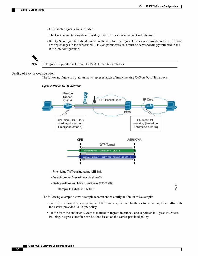
Quality of Service ConfigurationThe following figure is a diagrammatic representation of implementing QoS on 4G LTE network.
Figure 3: QoS on 4G LTE Network
The following example shows a sample recommended configuration. In this example:
• Traffic from the end user is marked in ISRG2 routers; this enables the customer to map their traffic withthe carrier-provided LTE QoS policy.
• Traffic from the end-user devices is marked in Ingress interfaces, and is policed in Egress interfaces.Policing in Egress interface can be done based on the carrier provided policy.
Cisco 4G LTE Software Configuration Guide52
Cisco 4G LTE Software ConfigurationCisco 4G LTE Features
• The wide area cellular network is a shared medium and hence it is a variable bandwidth environment.By designing and implementing an effective traffic control policy at the Egress interface (cellularinterface), radio resources can be efficiently utilized to support business critical applications. For theIOS QoS to work correctly, the onus is on the end user to determine the appropriate LTE bandwidth fortraffic shaping purposes.
In this example, the carrier has provided the following LTE policy:
• 1 default bearer: Best effort
• 1 Non-GBR dedicated bearer: Allow DSCP CS4: Rate-limited to 500 Kbps
• 1 GBR dedicated bearer: Allow DSCP CS5: rate limited to 50 Kbps
• Overall average bandwidth is taken into account and the egress traffic is shaped to 1.5 Mbps
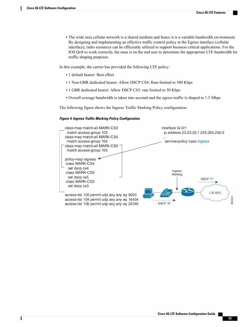
The following figure shows the Ingress Traffic Marking Policy configuration:
Figure 4: Ingress Traffic Marking Policy Configuration
Cisco 4G LTE Software Configuration Guide 53
Cisco 4G LTE Software ConfigurationCisco 4G LTE Features

The following figure shows the Egress Class-Based Traffic Control Policy configuration:
Figure 5: Egress Class-based Traffic Control Policy Configuration
For more information about configuring QoS features, see Quality of Service Solutions Configuration GuideLibrary, Cisco IOS Release 15M&T.
Troubleshooting QoSThe cellular interface notifies a user with a syslog message when QoS is enabled during the router boot-up,or when the modem attaches to the network. It also sends a message when a TFT profile is added, deleted, ormodified by the core network. Users need to change the configuration on their side to match TFT profile. Thefollowing table lists the syslog messages generated for various events.
Cisco 4G LTE Software Configuration Guide54
Cisco 4G LTE Software ConfigurationCisco 4G LTE Features

Table 5: Syslog Messages
DescriptionSyslog Message
The dedicated bearer has been added. Check the TFTrules of the dedicated bearer by using the showcellular command, and add QoS configurationaccordingly.
DEDICATED_BEARER_UP: Dedicated bearer(bearer_id=%d) in HWIC slot %d/%d is now UP
There could be a network issue that needs furtherinvestigation. Contact your carrier.DEDICATED_BEARER_DOWN:
Dedicated bearer (bearer_id=%d) in HWIC slot%d/%d is now down
The host QoS configuration may need to be modifiedto match the modem configuration. Check the TFTrules of the bearer by using the show cellularcommand, and configure the host QoS configurationto match the TFT rules.
DEDICATED_BEARER_DELETED: Dedicated bearer(bearer_id=%d) in HWIC slot %d/%d is nowdeleted
The dedicated bearer configuration has beenmodified.Check the TFT rules of the bearer by using the showcellular command, and configure the host QoSconfiguration to match the TFT rules.
DEDICATED_BEARER_MODIFIED: Dedicated bearer(bearer_id=%d) configuration in HWIC slot%d/%d is modified
Cellular Modem Link Recovery
The Cellular Modem Link Recovery feature is used to check whether the modem functions properly and bringback the modem to normal operation state if the modem is in inoperative state. When an inoperative state isidentified, the modem is reset (the cellular modem is power cycled). The link recovery feature is enabled bydefault, and can be disabled using Cisco IOS CLI.
There are four configurable parameters to adjust the behavior of cellular link recovery. The default valueshave been optimized for the best performance of the feature and changing it is not recommended unless advisedby Cisco.
The following table explains the cellular modem link recovery parameters.
Table 6: Cellular Modem Link Recovery Parameters
DescriptionParameter
This parameter defines the RSSI value below whichthe link recovery feature triggers additional scrutinyto look for potential issues and take action if needed.The range of this parameter can be set from -90 dBmto -125 dBm. The recommended and default value is-110 dBm.
rssi onset-threshold
Cisco 4G LTE Software Configuration Guide 55
Cisco 4G LTE Software ConfigurationCisco 4G LTE Features

DescriptionParameter
This parameter determines how often link recoverylooks for potential issues. The default value for thisparameter is 20 seconds which means, link recoveryfeature will be triggered every 20 seconds and lookat certain parameters to determine if there is apotential issue. You can configure the monitor-timerrange between 20 to 60 seconds. Increasing themonitor timer value above 20 seconds will increasethe response time of the feature.
monitor-timer
The wait-timer parameter is used in conjunction withthe debounce-count parameter to perform morefrequent, additional checks, once the link recoveryfeature has identified a potential issue that needs tobe recovered from, with a modem power-cycle. Thedefault value for wait-timer is 10 seconds and thedefault value for debounce- count is 6. With thissetting, once link recovery has identified aninoperative modem state, it performs additionalchecks every 10 seconds, up to 6 times, to determineif the issue has been resolved without a modem reset.Reducing the debounce-count and the wait-timermakes faster link recovery, while reducing themmayincrease the time for recovery. The configurable rangefor wait-timer is 5-60 seconds. The configurable rangefor debounce-count is 6-20 seconds.
wait-timer and debounce-count
Cellular Modem Link Recovery Monitoring and Statistics
When the cellular modem link recovery occurs and modem is reset, you can see the%CELLWAN-2-MODEM_DOWN message on the console logs. Effective with Cisco IOS release15.6(2.0c)T0, additionally there is a%CELLWAN-2-LINK_RECOVERY message which indicates thataction has been taken by the cellular modem link recovery feature.
Whenever the cellular modem link recovery is occurred, it updates the Modem timeouts counter under theModem Management Statistics section of the show controller cellular unit command output. Modemparameters at the last timeout section has information that helps to identify the cause of the issue that triggeredlink recovery
In the following example log, the messages, modem time out counter, and modem parameters at the last timeout are highlighted.
*Jul 19 17:15:18.980 PDT: %CELLWAN-2-LINK_RECOVERY: Cellular0/1/0: Cellular Modem has beenpower cycledRouter# show controller cellular 0/1/0Interface Cellular0/1/0LTE Adv WWAN NIM - Latin America Multimode LTE/DC-HSPA+/HSPA+/HSPA/UMTS/EDGE/GP unit 1manufacture id: 0x00001199 product id: 0x00009071Sierra Wireless Direct IP EM7430 modemGPS Feature: enabledGPS Mode Configured: not configuredGPS Status: NMEA Disabled
Cisco 4G LTE Software Configuration Guide56
Cisco 4G LTE Software ConfigurationCisco 4G LTE Features

Cellular Dual SIM details:---------------------------
SIM 0 is presentSIM 1 is presentSIM 0 is active SIM
Module OIR Details-----------------------------------------------Module type : NIM-LTEA-LAModule Serial Number : FOC20084WGPModule Last Inserted on : Tue Jul 19 10:16:34 2016-----------------------------------------------Module Reload Statistics-------------------------Soft OIR reloads = 0Hard OIR reloads = 0-------------------------
Modem Management Statistics---------------------------Modem resets = 1Modem user initiated resets = 0Modem user initiated power-cycles = 0Modem timeouts = 1Modem parameters at the last timeout:
LTE first time attach State was NoRadio Interface Technology Mode was AUTOOperating Mode was OnlineRSSI was -0 dBmPacket switch domain status was Not AttachedRegistration state(EMM) was Not RegisteredDownlink traffic was not present
Link recovery is ONRegistration check is ONRSSI threshold value is -110 dBmMonitor Timer value is 20 secondsWait Timer value is 10 secondsDebounce Count value is 6
Multiple Bearer SupportThe multiple bearer feature is supported on the Cisco 4G EHWICs and Cisco 4G ISRs. Each PDP context isa separate data link over a common 4G data connection. Each PDP context has its own IP address and its owndata and QoS profile. For each PDP context, a new IOS cellular interface is created once the EHWIC isinitialized. In addition, each cellular interface has a corresponding TTY line. This is similar to EHWICs withmultiple ports, for instance:
• Cellular 0/hwic_slot/0
• Cellular 0/hwic_slot/1
• Cellular 0/hwic_slot/2
The last number in the triple numbering scheme is the port number.Note
The multiple cellular interfaces behave independently. Any of them can be used to establish data connection.However, only the first interface, e.g. Cellular 0/hiwc_slot/0 can be used to exercise the full set of modemAT commands using the Reverse Telnet feature.
The HSPA cellular modem allows you to configure up to 16? profiles. The QoS profile configured for aninterface is selected by the ATDT*98*#profile_number# command in the chat script corresponding to a
Cisco 4G LTE Software Configuration Guide 57
Cisco 4G LTE Software ConfigurationMultiple Bearer Support

cellular interface. The basic data profile configuration is enhanced with the QoS profile configuration. Youmust use a different data/QoS profile for each cellular interface.
If both primary interfaces are used, you must create two separate chat scripts in the router configuration.Note
PLMN Search and SelectionStarting from Cisco IOS Release 15.5(3)M1, manual Public Land Mobile Network (PLMN) is supported onCisco 8xx routers and EHWICs. This feature allows you to search for available PLMNs and connect to oneof the PLMN.
Restrictions
The following restrictions apply for PLMN search and selection:
• Support in Cisco LTE 2.0 and MC73xx modem series and above.
• You have to verify whether your cellular service supports roaming or not.
• You have to use a SIM card that supports roaming.
• This feature is not supported on 4G+WiFi platforms.
• Supported firmware version is 5.5.58.x or later.
• Supported IOS release is Cisco IOS Release 15.5(3)M1 or later.
Commands
Use the following commands on fixed platforms:
• cellular x lte plmn search
• show cellular x network
• cellular x lte plmn select mode mcc mnc rat duration
Use the following commands on EHWICs:
• cellular x/x/x lte plmn search
• show cellular x/x/x network
• cellular x/x/x lte plmn select mode mcc mnc rat duration
Searching the Network
You can use the cellular 0 lte plmn search command to search for available PLMNs. The following exampleshows how to search for networks:
router#cellular 0 lte plmn searchSearching for available PLMNs.This may take up to 3 minutes.
Cisco 4G LTE Software Configuration Guide58
Cisco 4G LTE Software ConfigurationPLMN Search and Selection

Please wait...........................PLMN search done. Please use "show cellular 0 network" to see available PLMNSAfter the search, use the show cellular 0 network command to see the available networks:
router#show cellular 0 networkCurrent System Time = Fri Sep 18 18:49:24 2015Current Service Status = NormalCurrent Service = Packet switchedCurrent Roaming Status = RoamingNetwork Selection Mode = ManualNetwork = O2 - UKMobile Country Code (MCC) = 234Mobile Network Code (MNC) = 10Packet switch domain(PS) state = AttachedLocation Area Code (LAC) = 4931Cell ID = 34319Available PLMNs:Idx MCC MNC RAT Desc1 234 10 umts O2 - UK2 234 10 gsm O2 - UK3 234 20 umts 3 UK4 234 30 umts EE5 234 15 gsm voda UK6 234 33 gsm EE7 234 20 lte 3 UK8 234 30 gsm EE9 234 15 umts voda UK10 234 30 lte EE11 234 10 lte O2 - UK12 234 15 lte voda UK
Selecting the Network
There are three ways you can select an available network: Auto mode, Force Mode, and Manual mode. InAuto mode, your router will connect automatically to a network preferred by the SIM. In Force mode, therouter is forced to select an available or known network without performing a network search. If a networkis not available or the router is unable to attach to a network, then the router will remain in a ‘Not attached’state. You can use the cellular x lte plan select auto command to attach the router to a network preferred bythe SIM. In Manual mode, you can select an available network from your search result.
The following example shows how to select a network manually:
router#cellular 0 lte plmn select manual ?0-999 Mobile Country Code (MCC)router#cellular 0 lte plmn select manual 234 ?0-999 Mobile Network Code (MNC)router#cellular 0 lte plmn select manual 234 10 ?gsm GSMlte LTEumts UMTS
router#cellular 0 lte plmn select manual 234 10 gsm ?permanent PERMANENTpower-cycle POWER_CYCLE
router#cellular 0 lte plmn select manual 234 10 gsm powerouter#cellular 0 lte plmn select manual 234 10 gsm power-cycle ?router#cellular 0 lte plmn select manual 234 10 gsm power-cycleThe following example shows how to force a network selection:
router#cellular 0 lte plmn select force ?0-999 Mobile Country Code (MCC)router#cellular 0 lte plmn select force 310 ?0-999 Mobile Network Code (MNC)router#cellular 0 lte plmn select force 310 410 ?2-3 MNC Digits Ex 23 means 2 Digits, 023 Means 3 Digitsrouter#cellular 0 lte plmn select force 310 410 2 ?gsm GSM
Cisco 4G LTE Software Configuration Guide 59
Cisco 4G LTE Software ConfigurationPLMN Search and Selection

lte LTEumts UMTS
router#cellular 0 lte plmn select force 310 410 2 lrouter#cellular 0 lte plmn select force 310 410 2 lte ?permanent PERMANENTpower-cycle POWER_CYCLE
Router#cellular 0 lte plmn select force 310 410 2 lte power-cycle ?Router#cellular 0 lte plmn select force 310 410 2 lte power-cycle
Verifying PLMN Selection
Use show cellular 0 network command to verify the PLMN selection:
router#show cellular 0 networkCurrent System Time = Fri Sep 18 18:53:25 2015Current Service Status = NormalCurrent Service = Packet switchedCurrent Roaming Status = RoamingNetwork Selection Mode = ManualNetwork = O2 - UKMobile Country Code (MCC) = 234Mobile Network Code (MNC) = 10Packet switch domain(PS) state = AttachedLocation Area Code (LAC) = 4931Cell ID = 34319Available PLMNs:Idx MCC MNC RAT Desc1 234 10 umts O2 - UK2 234 10 gsm O2 - UK3 234 20 umts 3 UK4 234 30 umts EE5 234 15 gsm voda UK6 234 33 gsm EE7 234 20 lte 3 UK8 234 30 gsm EE9 234 15 umts voda UK10 234 30 lte EE11 234 10 lte O2 - UK12 234 15 lte voda UKrouter#show cellular 0 radioRadio power mode = ONChannel Number = 122Current Band = GSM 900 ExtendedCurrent RSSI = -48 dBmCurrent ECIO = -127 dBmRadio Access Technology(RAT) Preference = GSMRadio Access Technology(RAT) Selected = EDGE
Some networks may not allow the router to connect. In such cases, you have to choose a different network.Note
Restart your modem if the router is not able to connect to any network.Note
SNMP MIBs
The following SimpleManagement Network Protocol (SNMP)MIBs are supported on Cisco 4G LTEWWANEHWICs, Cisco 819 Series 4G LTE ISRs and Cisco C880 Series 4G LTE ISRs and Cisco C890 Series 4GLTE Series ISRs:
• IF-MIB
Cisco 4G LTE Software Configuration Guide60
Cisco 4G LTE Software ConfigurationPLMN Search and Selection

• ENTITY-MIB
• CISCO-WAN-3G-MIB
For the CISCO-WAN-3G-MIB, the following tables and sub-tables are supported for 3G and LTE technologies:
• ciscoWan3gMIB(661)
• ciscoWan3gMIBNotifs(0)
• ciscoWan3gMIBObjects(1)
• c3gWanCommonTable(1)
• c3gWanGsm(3)
• c3gGsmIdentityTable(1)
• c3gGsmNetworkTable(2)
• c3gGsmPdpProfile(3)
• c3gGsmPdpProfileTable(1)
• c3gGsmPacketSessionTable(2)
• c3gGsmRadio(4)
• c3gGsmRadioTable(1)
• c3gGsmSecurity(5)
• c3gGsmSecurityTable(1)
You can download the MIBs from the Cisco MIB Locator at http://www.cisco.com/go/mibs.
How to Configure Cisco 4G LTE
Verifying Modem Signal Strength and Service AvailabilityFor the EHWIC, the unit argument identifies the router slot, WIC slot, and port separated by slashes (0/0/0).For the Cisco 800 Series 4G LTE ISRs, the unit argument identifies slot “0” for all commands.For 4G-LTE EHWICs, the numbering for slot 0, wic 0, and port 0 is 0/0/0 for all commands. For Cisco 800Series 4G LTE fixed platforms, use slot “0” for all commands.
SUMMARY STEPS
1. show cellular unit network2. show cellular unit radio3. show cellular unit profile4. show cellular unit security5. show cellular unit all
Cisco 4G LTE Software Configuration Guide 61
Cisco 4G LTE Software ConfigurationHow to Configure Cisco 4G LTE

DETAILED STEPS
PurposeCommand or Action
Displays information about the carrier network, cell site, andavailable service.
show cellular unit network
Example:
Device# show cellular 0/0/0 network
Step 1
Shows the radio signal strength.show cellular unit radioStep 2
Example:
Device# show cellular 0/0/0 radio
The RSSI should be better than –90 dBm for steadyand reliable connection.
Note
Shows information about the modem data profiles created.show cellular unit profile
Example:
Device# show cellular 0/0/0 profile
Step 3
Shows the security information for the modem, such as SIMand modem lock status.
show cellular unit security
Example:
Device# show cellular 0/0/0 security
Step 4
Shows consolidated information about the modem, profilescreated, radio signal strength, network security, and so on.
show cellular unit all
Example:
Device# show cellular 0/0/0 all
Step 5
Creating, Modifying, or Deleting Modem Data Profiles
SUMMARY STEPS
1. cellular unit lte profile [create | delete] profile-number [apn [authentication [username password[bearer-type]]]]
DETAILED STEPS
PurposeCommand or Action
Creates, modifies, or deletes a modem data profile in the privileged EXEC mode.cellular unit lte profile [create |delete] profile-number [apn
Step 1
• profile-number—Specifies the profile number created for the modem.[authentication [username password[bearer-type]]]] • apn—Specifies an Access Point Name (APN) in the profile. AnAPN is provided
by your service provider. Only a single APN can be specified in a single profile.
Cisco 4G LTE Software Configuration Guide62
Cisco 4G LTE Software ConfigurationCreating, Modifying, or Deleting Modem Data Profiles

PurposeCommand or Action
Example:Device# cellular 0/0/0 lteprofile create 2 apn.com papusername pwd ipv4
• authentication—Specifies the authentication type used. Acceptable parametersare chap, none (no authentication), pap, and pap_chap (PAP or CHAPauthentication).
• username password—Provided by service provider.
• bearer-type—Specifies the type of data payload exchanged over the air linkwhen the packet data session is established with this profile. Acceptabledata type parameters are: ipv4, ipv6, and ipv4v6 (IPv4 and IPv6).
Entering this command results in the creation or modification of both the3GPP and 3GPP2 profiles with the same parameters for the MC7750 andMC7350 modems.
Note
Configuring a SIM for Data Calls
Locking and Unlocking a SIM Card Using a PIN Code
Perform this task to lock or unlock a SIM card given by your service provider.
The SIM card gets blocked if the wrong PIN is entered three consecutive times. Make sure you enter thecorrect PIN the SIM is configured with. If your SIM card gets blocked, contact your service provider for aPUK code. Using the PUK code, you can unblock the SIM card.
For the EHWIC, the unit argument identifies the router slot, WIC slot, and port separated by slashes(0/0/0). For the Cisco 800 Series 4G LTE ISRs, the unit argument identifies slot “0” for all commands.
Note
SUMMARY STEPS
1. cellular unit lte sim {lock | unlock} pin
DETAILED STEPS
PurposeCommand or Action
Locks or unlocks the SIM card using a PIN code.cellular unit lte sim {lock | unlock} pinStep 1
Example:
Device# cellular 0/0/0 lte sim lock 1111
• pin—A code (4 to 8 digits long) provided by your carrierto lock or unlock the SIM card.
Cisco 4G LTE Software Configuration Guide 63
Cisco 4G LTE Software ConfigurationConfiguring a SIM for Data Calls

Changing the PIN Code
Perform this task to change the PIN code of a SIM.
For the EHWIC, the unit argument identifies the router slot, WIC slot, and port separated by slashes(0/0/0). For the Cisco 800 Series 4G LTE ISRs, the unit argument identifies slot “0” for all commands.
Note
SUMMARY STEPS
1. cellular unit lte sim change-pin pin new-pin
DETAILED STEPS
PurposeCommand or Action
Changes the assigned PIN code. SIM should be in lockedstate when the PIN is being changed.
cellular unit lte sim change-pin pin new-pin
Example:
Device# cellular 0/0/0 lte sim change-pin 1111 1234
Step 1
Verifying the Security Information of a Modem
Perform this task to verify the security information of a modem.
For the EHWIC, the unit argument identifies the router slot, WIC slot, and port separated by slashes(0/0/0). For the Cisco 800 Series 4G LTE ISRs, the unit argument identifies slot “0” for all commands.
Note
SUMMARY STEPS
1. show cellular unit security
DETAILED STEPS
PurposeCommand or Action
Shows the security information of the modem, includingthe SIM lock status.
show cellular unit security
Example:
Device# show cellular 0/0/0 security
Step 1
Cisco 4G LTE Software Configuration Guide64
Cisco 4G LTE Software ConfigurationConfiguring a SIM for Data Calls

Configuring Automatic Authentication for a Locked SIM
An unencrypted PIN can be configured to activate the Card Holder Verification (CHV1) code that authenticatesa modem.
The SIM card gets blocked if the wrong PIN is entered three consecutive times. Make sure you enter thecorrect PIN the SIM is configured with. If your SIM card gets blocked, contact your service provider for aPUK code.
Follow these procedures when using an unencrypted Level 0 PIN to configure CHV1. For instructions onhow to configure CHV1 using an encrypted Level 7 PIN, see the Configuring an Encrypted PIN for a SIM,on page 66.
A SIM should be locked for SIM authentication to work. To verify the SIM’s status, use the show cellularunit security command.
For the EHWIC, the unit argument identifies the router slot, WIC slot, and port separated by slashes (0/0/0).For the Cisco 800 Series 4G LTE ISRs, the unit argument identifies slot “0” for all commands.
SUMMARY STEPS
1. configure terminal2. controller cellular unit3. Do one of the following: lte sim authenticate 0 pin lte sim authenticate 0 pin slot {0 | 1}
DETAILED STEPS
PurposeCommand or Action
Enters global configuration mode.configure terminal
Example:
Device# configure terminal
Step 1
Enters the cellular controller configuration mode.controller cellular unit
Example:
Device(config)# controller cellular0/0
Step 2
Authenticates the SIM CHV1 code by using an unencrypted (0) keyword andPIN. This PIN is sent to the modem for authentication with each subsequent
Do one of the following: lte simauthenticate 0 pin lte sim authenticate 0pin slot {0 | 1}
Step 3
LTE connection. If authentication passes based on the configured PIN, thedata call is allowed. If authentication fails, the modem does not initiate thedata call.Example:
Device(config-controller)# lte simauthenticate 0 1111
• For the Cisco 4G EHWICs that do not support dual SIM feature, usethe first command.
• For the Cisco 800 Series 4G LTE ISRs with dual SIM feature, use thesecond command.
Cisco 4G LTE Software Configuration Guide 65
Cisco 4G LTE Software ConfigurationConfiguring a SIM for Data Calls
PurposeCommand or Action
This command is valid only when an unencrypted PIN is used. Toconfigure CHV1 code using an encrypted PIN, see the Configuringan Encrypted PIN for a SIM, on page 66. The slot keyword and itsoptions are only available onCisco 800 Series 4G LTE ISRs whichsupports the dual SIM feature.
Note
Configuring an Encrypted PIN for a SIM
To configure an encrypted PIN, the scrambled value of the PIN must be obtained. To get the scrambled Level7 PIN and to configure the SIM CHV1 code for verification using this encrypted PIN, enter the followingcommands in the EXEC mode.
When obtaining the encrypted PIN for a SIM, a username and password are created by configuring passwordencryption, defining the username and associated password, copying the resulting scrambled password, andusing this scrambled password in the SIM authentication command. After the scrambled PIN has been obtainedand used in SIM authentication, the username created can be deleted from the Cisco IOS configuration.
A SIM should be locked for SIM authentication to work. To verify the SIM’s status, use the show cellularunit security command.
For the EHWIC, the unit argument identifies the router slot, WIC slot, and port separated by slashes (0/0/0).For the Cisco 800 Series 4G LTE ISRs, the unit argument identifies slot “0” for all commands.
SUMMARY STEPS
1. configure terminal2. service password-encryption3. username name privilege 0 password pin4. do show run | i name5. controller cellular unit6. Do one of the following:
• lte sim authenticate {0 | 7} pin
• lte sim authenticate {0 | 7} pin slot {0 | 1}
7. exit8. no username name9. no service password-encryption
Cisco 4G LTE Software Configuration Guide66
Cisco 4G LTE Software ConfigurationConfiguring a SIM for Data Calls

DETAILED STEPS
PurposeCommand or Action
Enters global configuration mode.configure terminal
Example:
Device# configure terminal
Step 1
Enables password encryption.service password-encryption
Example:
Device(config)# servicepassword-encryption
Step 2
Creates username and password.username name privilege 0 password pinStep 3
Example:
Device(config)# username SIM privilege 0password 1111
• name—Specifies the username.
• pin—Specifies the four- to eight-digit PIN code.
Shows the username configuration line with the encrypted level 7PIN for the username created in Step 3 (user “SIM” in the exampleshown).
do show run | i name
Example:
Device(config)# do show run | i SIM
Step 4
Copy the scrambled password for use in Step 6 (as the PIN).
Enters the cellular controller configuration mode.controller cellular unit
Example:
Device(config)# controller cellular 0/0
Step 5
Authenticates the SIMCHV1 code by using the encrypted keyword7 and the scrambled PIN from Step 4. The PIN is sent to the modem
Do one of the following:Step 6
• lte sim authenticate {0 | 7} pin for authentication with each subsequent LTE connection. Ifauthentication passes based on the configured PIN, the data call is• lte sim authenticate {0 | 7} pin slot {0 | 1}allowed. If authentication fails, the modem does not initiate thedata call.
Example:
Device(config-controller)# lte simauthenticate 7 055A575E70
For Cisco 4G LTE WWAN EHWICs, use the first command.
For the Cisco 819(H)G-4G-G ISR that supports dual SIM feature,use the second command.
The slot keyword and its options are available only onCisco 800 Series 4G LTE ISRs which supports the dualSIM feature.
Note
(Optional) Exits the cellular controller configuration mode.exit
Example:
Device(config-controller)# exit
Step 7
Cisco 4G LTE Software Configuration Guide 67
Cisco 4G LTE Software ConfigurationConfiguring a SIM for Data Calls

PurposeCommand or Action
(Optional) Removes the username and password created in Step 3.no username name
Example:
Device(config)# no username SIM
Step 8
(Optional) Disables password encryption.no service password-encryption
Example:
Device(config)# no servicepassword-encryption
Step 9
Applying a Modem Profile in a SIM Configuration
SUMMARY STEPS
1. configure terminal2. controller cellular unit3. Do one of the following:
• lte sim data-profile number
• attach-profile number lte sim profile number attach-profile number slot {0 | 1}
DETAILED STEPS
PurposeCommand or Action
Enters the global configuration mode.configure terminal
Example:
Device# configure terminal
Step 1
Enters the cellular controller configuration mode.controller cellular unit
Example:
Device(config)# controller cellular 0/0
Step 2
(All MC77xx modems) Applies the configured profile number tothe SIM and its slot number. The default (primary) slot is 0.
Do one of the following:Step 3
• lte sim data-profile number• For the Cisco 4G EHWICs that do not support dual SIMfeature, use the first command.• attach-profile number lte sim profile number
attach-profile number slot {0 | 1}
Cisco 4G LTE Software Configuration Guide68
Cisco 4G LTE Software ConfigurationConfiguring a SIM for Data Calls

PurposeCommand or Action
• For the Cisco 800 Series 4G LTE ISRs with dual SIMfeature, use the second command.Example:
Device(config-controller)# lte simdata-profile 2 attach-profile 1 slot 0
• attach profile—profile used by the modem to attach to theLTE network.
Example:
Device(config-controller)# lte simdata-profile 3 attach-profile 1 slot 1
• data profile—profile used to send and receive data over thecellular network.
The slot keyword and its options are available only on Cisco800 Series 4G LTE ISRs which supports the Dual SIMfeature.
Note
Configuring a Dual SIM
You can manually activate a SIM using the cellular 0 lte sim activate slot 0 or 1 command.Note
SUMMARY STEPS
1. configure terminal2. controller cellular unit3. lte sim primary slot4. lte sim max-retry number5. lte failovertimer timeout-period6. lte sim data-profile number attach-profile number slot {0 | 1}
DETAILED STEPS
PurposeCommand or Action
Enters the global configuration mode.configure terminal
Example:Device# configure terminal
Step 1
Enters the cellular controller configuration mode.controller cellular unit
Example:Device(config)# controller cellular 0/0
Step 2
(Optional) Enters either slot number 0 or 1 of the primary SIM.lte sim primary slot
Example:Device(config-controller)# lte sim primary 1
Step 3
Cisco 4G LTE Software Configuration Guide 69
Cisco 4G LTE Software ConfigurationConfiguring a SIM for Data Calls

PurposeCommand or Action
(Optional) Specifies the maximum number of failover retriesfrom 1 to 65535. The default value is 10.
lte sim max-retry number
Example:Device(config-controller)# lte sim max-retry20
Step 4
(Optional) By default, the failover time period is 2 minutesbefore the primary SIM switches over to the secondary SIMif service becomes unavailable.
lte failovertimer timeout-period
Example:Device(config-controller)# lte failovertimer6
Step 5
Specify a failover timeout value between 1 and 7 minutesbefore a switchover occurs.
Applies the configured profile number to the SIM and its slotnumber. The default (primary) slot is 0.
lte sim data-profile number attach-profile numberslot {0 | 1}
Step 6
Example:Device(config-controller)# lte sim data-profile2 attach-profile 1 slot 0
You must also identify the primary and secondary SIM for theconfigured profile when two SIMs are presented.
Example:Device(config-controller)# lte sim data-profile2 attach-profile 1 slot 1
Data Call SetupThe following figure shows a typical data call setup.
Figure 6: Data Call Setup with EHWIC-4G-LTE
To set up a data call, use the following procedures:
Configuring the Cellular Interface
To configure the cellular interface, enter the following commands starting in EXEC mode.
Cisco 4G LTE Software Configuration Guide70
Cisco 4G LTE Software ConfigurationData Call Setup

For the EHWIC, the unit argument identifies the router slot, WIC slot, and port separated by slashes(0/0/0). For the Cisco 800 Series 4G LTE ISRs, the unit argument identifies slot “0” for all commands.
Note
Starting from Cisco IOS Release 15.3(3)M and 15.3(1)T, the chat-script configuration, including dialerin-band, dialer string, and script dialer, is auto-generated based on the modem type plugged in. The 3Gand 4G EHWIC SKUs and the fixed 3G and 4G routers support these configuration changes.
Note
SUMMARY STEPS
1. configure terminal2. interface cellular unit3. ip address negotiated4. encapsulation slip5. dialer in-band6. dialer string string7. dialer-group group-number8. exit9. chat-script script-name ”” “AT!CALL” TIMEOUT timeout-value “OK”10. ip route network-number network-mask {ip-address | interface} [administrative distance] [name name]11. dialer-list dialer-group protocol protocol-name {permit | deny | list access-list-number | access-group}12. line unit13. script dialer regular-expression
DETAILED STEPS
PurposeCommand or Action
Enters global configuration mode.configure terminal
Example:
Device# configure terminal
Step 1
Specifies the cellular interface.interface cellular unit
Example:
Device(config)# interface cellular 0/0/0
Step 2
Specifies that the IP address for a particular interface isdynamically obtained.
ip address negotiated
Example:
Device(config-if)# ip address negotiated
Step 3
Cisco 4G LTE Software Configuration Guide 71
Cisco 4G LTE Software ConfigurationData Call Setup

PurposeCommand or Action
Specifies Serial Line Internet Protocol (SLIP) encapsulationfor an interface configured for dedicated asynchronous
encapsulation slip
Example:
Device(config-if)# encapsulation slip
Step 4
mode or dial-on-demand routing (DDR). This is the defaultfor asynchronous interfaces.
Enables DDR and configures the specified serial interfaceto use in-band dialing.
dialer in-band
Example:
Device(config-if)# dialer in-band
Step 5
Specifies the number or string to dial.dialer string string
Example:
Device(config-if)# dialer string lte
Step 6
Specifies the number of the dialer access group to whichthe specific interface belongs.
dialer-group group-number
Example:
Device(config-if)# dialer-group 1
Step 7
Enters the global configuration mode.exit
Example:
Device(config-if)# exit
Step 8
Defines the ATDT commands when the dialer is initiated.chat-script script-name ”” “AT!CALL” TIMEOUTtimeout-value “OK”
Step 9
Example:
Device(config)# chat-script lte"" "AT!CALL"TIMEOUT 60 "OK“
Establishes a floating static route with the configuredadministrative distance through the specified interface.
ip route network-number network-mask {ip-address |interface} [administrative distance] [name name]
Step 10
Example:
Device(config)# ip route 209.165.200.225255.255.255.224 cellular 0/0/0
A higher administrative distance should beconfigured for the route through the backupinterface so that it is used only when the primaryinterface is down.
Note
Creates a dialer list for traffic of interest and permits accessto an entire protocol.
dialer-list dialer-group protocol protocol-name {permit| deny | list access-list-number | access-group}
Example:
Device(config)# dialer-list 1 protocol ip list1
Step 11
Cisco 4G LTE Software Configuration Guide72
Cisco 4G LTE Software ConfigurationData Call Setup

PurposeCommand or Action
Specifies the line configuration mode.line unit
Example:
Device(config)# line 0/0/0
Step 12
Specifies a default modem chat script.script dialer regular-expression
Example:
Device(config-line)# script dialer lte
Step 13
What to Do Next
If a tunnel interface is configured with ip unnumbered cellular 0/0/0, it is necessary to configure theactual static IP address under the cellular interface, in place of ip address negotiated.
Note
Configuring DDR
To configure DDR for the cellular interface, enter the following commands starting in EXEC mode.
For the EHWIC, the unit argument identifies the router slot, WIC slot, and port separated by slashes(0/0/0). For the Cisco 800 Series 4G LTE ISRs, the unit argument identifies slot “0” for all commands.
Note
Cisco 4G LTE Software Configuration Guide 73
Cisco 4G LTE Software ConfigurationData Call Setup

SUMMARY STEPS
1. configure terminal2. interface cellular unit3. ip address negotiated4. encapsulation slip5. dialer in-band6. dialer pool-member number7. interface dialer number8. ip address negotiated9. encapsulation slip10. dialer pool number11. dialer idle-timeout seconds12. dialer string string13. dialer-group group-number14. exit15. dialer-list dialer-group protocol protocol-name {permit | deny | list access-list-number | access-group}16. access-list access-list-number permit ip-source-address17. line unit18. script dialer regular-expression19. exit20. chat-script script-name ”” “AT!CALL” TIMEOUT timeout-value “OK”
DETAILED STEPS
PurposeCommand or Action
Enters global configuration mode.configure terminal
Example:
Device# configure terminal
Step 1
Specifies the cellular interface.interface cellular unit
Example:
Device(config)# interface cellular 0/0/0
Step 2
Specifies that the IP address for a particular interface isdynamically obtained.
ip address negotiated
Example:
Device(config-if)# ip address negotiated
Step 3
Example:
Cisco 4G LTE Software Configuration Guide74
Cisco 4G LTE Software ConfigurationData Call Setup

PurposeCommand or Action
Specifies Serial Line Internet Protocol (SLIP) encapsulationfor an interface configured for dedicated asynchronous
encapsulation slip
Example:
Device(config-if)# encapsulation slip
Step 4
mode or dial-on-demand routing (DDR). This is the defaultfor asynchronous interfaces.
Enables DDR and configures the specified serial interfaceto use in-band dialing.
dialer in-band
Example:
Device(config-if)# dialer in-band
Step 5
Specifies the number of a dialer profile’s dialing pool towhich the specific interface belongs.
dialer pool-member number
Example:
Device(config-if)# dialer pool-member 1
Step 6
Specifies the number of a dialer rotary group to which thespecific interface belongs.
interface dialer number
Example:
Device(config-if)# interface dialer 1
Step 7
Specifies that the IP address for a particular interface isdynamically obtained.
ip address negotiated
Example:
Device(config-if)# ip address negotiated
Step 8
Specifies Serial Line Internet Protocol (SLIP) encapsulationfor an interface configured for dedicated asynchronous
encapsulation slip
Example:
Device(config-if)# encapsulation slip
Step 9
mode or dial-on-demand routing (DDR). This is the defaultfor asynchronous interfaces.
Specifies the number of a dialing pool that the dialerinterface can use to connect to a specific destinationsubnetwork.
dialer pool number
Example:
Device(config-if)# dialer pool 1
Step 10
Specifies the duration of idle time, in seconds, after whicha line will be disconnected.
dialer idle-timeout seconds
Example:
Device(config-if)# dialer idle-timeout 30
Step 11
Specifies the number or string to dial.dialer string string
Example:
Device(config-if)# dialer string lte
Step 12
Cisco 4G LTE Software Configuration Guide 75
Cisco 4G LTE Software ConfigurationData Call Setup
PurposeCommand or Action
Specifies the number of the dialer access group to whichthe specific interface belongs.
dialer-group group-number
Example:
Device(config-if)# dialer-group 1
Step 13
Enters the global configuration mode.exit
Example:
Device(config-if)# exit
Step 14
Creates a dialer list for traffic of interest and permits accessto an entire protocol.
dialer-list dialer-group protocol protocol-name{permit | deny | list access-list-number | access-group}
Example:
Device(config)# dialer-list 1 protocol ip list1
Step 15
Defines traffic of interest.access-list access-list-number permit ip-source-address
Example:
Device(config)# access-list 1 permit any
Step 16
Specifies the line configuration mode.line unit
Example:
Device(config)# line 0/0/0
Step 17
Specifies a default modem chat script.script dialer regular-expression
Example:
Device(config-line)# script dialer lte
Step 18
Exits line configuration mode.exit
Example:
Device(config-line)# exit
Step 19
Defines the ATDT commands when the dialer is initiated.chat-script script-name ”” “AT!CALL” TIMEOUTtimeout-value “OK”
Step 20
Example:
Device(config)# chat-script lte"" "AT!CALL"TIMEOUT 60 "OK“
Cisco 4G LTE Software Configuration Guide76
Cisco 4G LTE Software ConfigurationData Call Setup

Configuring DDR Backup
To monitor the primary connection and initiate the backup connection when needed, the router can use oneof the following methods:
• Backup Interface—The backup interface that stays in standby mode until the primary interface lineprotocol is detected as down and then is brought up.
• Floating Static Route—The route through the backup interface has an administrative distance that isgreater than the administrative distance of the primary connection route and therefore would not be inthe routing table until the primary interface goes down.
• Dialer Watch—Dialer watch is a backup feature that integrates dial backup with routing capabilities.
Configuring Interfaces to Use a Backup Interface
You cannot configure a backup interface for the cellular interface and any other asynchronous serialinterface.
Note
To configure one or more interfaces to use a backup interface, use the following commands, beginning inglobal configuration mode.
SUMMARY STEPS
1. interface type number2. backup interface cellular number3. backup delay enable-delay-period disable-delay-period
DETAILED STEPS
PurposeCommand or Action
Specifies the interface to be backed up and begins interfaceconfiguration mode.
interface type number
Example:
Device(config)# interface atm 0/0/0
Step 1
Specifies the cellular interface as backup.backup interface cellular number
Example:
Device(config-if)# backup interface cellular0/0/0
Step 2
Specifies delay between the physical interface going downand the backup interface being enabled and between the
backup delay enable-delay-period disable-delay-period
Example:
Device(config-if)# backup delay 0 10
Step 3
physical interface coming back up and the backup beingdisabled.
Cisco 4G LTE Software Configuration Guide 77
Cisco 4G LTE Software ConfigurationData Call Setup
Enabling 4G GPS and NMEA Data StreamingGPS NMEA data streaming to external NMEA 2.0-compliant GPS plotter applications can be enabled onCisco 4G LTE EHWICs, Cisco 819 Series 4G LTE ISRs, Cisco C880 Series 4G LTE ISRs, and Cisco C890Series 4G LTE ISRs.
For an EHWIC, the unit argument identifies the router slot, WIC slot, and the port, and is separated byslashes (0/0/0). For the Cisco 800 Series 4G LTE ISRs, the unit argument identifies slot 0 for all commands.
Note
SUMMARY STEPS
1. configure terminal2. controller cellular unit3. lte gps enable4. lte gps mode standalone5. Do one of the following:
• lte gps nmea {ip | serial [streaming]}
• lte gps nmea
6. end7. show cellular unit gps8. show cellular unit gps detail9. show running config10. show line11. telnet ip address port
DETAILED STEPS
Step 1 configure terminal
Example:
Device# configure terminalEnters the configuration mode.
Step 2 controller cellular unit
Example:
Device(config)# controller cellular 0Enters the controller cellular configuration mode.
Step 3 lte gps enable
Cisco 4G LTE Software Configuration Guide78
Cisco 4G LTE Software ConfigurationEnabling 4G GPS and NMEA Data Streaming

Example:
Device(config-controller)# lte gps enable(Optional) GPS is enabled by default. Use this command to enable the GPS feature if GPS has been disabled for anyreason.
Step 4 lte gps mode standalone
Example:
Device(config-controller)# lte gps mode standaloneEnables the standalone GPS mode.
Step 5 Do one of the following:
• lte gps nmea {ip | serial [streaming]}
• lte gps nmea
Example:Device(config-controller)# lte gps nmea ipEnables NMEA streaming. Cisco 4G LTE EHWICs support only IP NMEA streaming. Therefore, IP interface and serialinterface options are unavailable. Cisco 819 4G LTE ISRs, Cisco C880 Series 4G LTE ISRs, and Cisco C890 Series 4GLTE ISRs support the following NMEA streaming options:
• ip—NMEA over IP interface.
• serial—NMEA over serial interface.
• streaming—Parameters are: 38400 (bps baud rate), 4800 (bps baud rate, which is the default) line-config (use ttyline configuration).
Effective with Cisco IOS release 15.4(3)T, the lte gps nmea serial ip command is available on Cisco 800 seriesrouters with serial interfaces only.
Note
Step 6 end
Example:
Device(config-controller)# endExits the controller configuration mode and returns to the privileged EXEC mode.
Step 7 show cellular unit gps
Example:Device# show cellular 0/0/0 gps
GPS Info-------------GPS Feature: enabledGPS Port Selected: DIV portGPS State: GPS enabledGPS Mode Configured: standaloneLast Location Fix Error: Offline [0x0]GPS Error Count: 13Latitude: 37 Deg 24 Min 58 Sec NorthLongitude: 121 Deg 55 Min 7 Sec West
Cisco 4G LTE Software Configuration Guide 79
Cisco 4G LTE Software ConfigurationEnabling 4G GPS and NMEA Data Streaming

Timestamp (GMT): Thu Aug 15 14:23:35 2013
Fix type index: 0, Height: 15 mDisplays a summary of the following GPS data:
• GPS state information (GPS disabled, GPS acquiring, GPS enabled)
• GPS mode configured (standalone)
• GPS location and timestamp information
• GPS satellite information
• GPS feature (enabled or disabled)
• GPS port selected (Dedicated GPS and GPS port with voltage-no-bias)
Step 8 show cellular unit gps detail
Example:Device# show cellular 0 gps detail
GPS Info-------------GPS Feature: enabledGPS Port Selected: DIV portGPS State: GPS enabledGPS Mode Configured: standaloneLast Location Fix Error: Offline [0x0]GPS Error Count: 71Latitude: 37 Deg 24 Min 58 Sec NorthLongitude: 121 Deg 55 Min 7 Sec WestTimestamp (GMT): Fri Aug 16 10:46:25 2013
Fix type index: 0, Height: 20 mHDOP: 0.8, GPS Mode Used: standalone
Satellite Info----------------Satellite #1, elevation 18, azimuth 52, SNR 30 *Satellite #4, elevation 13, azimuth 165, SNR 29 *Satellite #7, elevation 3, azimuth 133, SNR 22Satellite #8, elevation 33, azimuth 126, SNR 29 *Satellite #9, elevation 33, azimuth 133, SNR 0 *Satellite #11, elevation 4, azimuth 39, SNR 0Satellite #15, elevation 29, azimuth 284, SNR 0 *Satellite #17, elevation 84, azimuth 118, SNR 0 *Satellite #26, elevation 38, azimuth 224, SNR 0Displays detailed GPS data.
Step 9 show running config
Example:Device# show running config
!controller Cellular 0lte gps mode standalonelte gps nmea ip!Shows the output of the configuration.
Step 10 show line
Cisco 4G LTE Software Configuration Guide80
Cisco 4G LTE Software ConfigurationEnabling 4G GPS and NMEA Data Streaming

Example:Device# show line
Tty Typ Tx/Rx A Modem Roty AccO AccI Uses Noise Overruns Int* 0 CTY - - - - - 0 0 0/0 -
1 AUX 0/0 - - - - - 0 0 0/0 -2 TTY 9600/9600 - - - - - 0 0 0/0 -
I 3 TTY - inout - - - 0 0 0/0 Ce0I 6 TTY - inout - - - 0 24101 0/0 NM0/0/5
10 VTY - - - - - 0 0 0/0 -11 VTY - - - - - 0 0 0/0 -12 VTY - - - - - 0 0 0/0 -13 VTY - - - - - 0 0 0/0 -14 VTY - - - - - 0 0 0/0 -
Line(s) not in async mode -or- with no hardware support:4-5, 7-9Shows the async port number.
After NMEA is configured, Cisco IOS creates a n NMEA async port. The port number is platform dependent. In thisexample, the async port number is line 6.
Step 11 telnet ip address port
Example:Device# telnet 10.1.1.1 2006
Trying 10.1.1.1, 2006 ... Open$GPRMC,,V,,,,,,,,,,N*53$GPGSV,3,1,11,01,17,049,34,04,16,164,30,08,29,129,32,09,29,136,38*70$GPGSV,3,2,11,15,29,281,37,17,83,073,36,28,,,41,07,00,135,*4B$GPGSV,3,3,11,11,01,037,,12,00,272,,24,18,313,*46$GLGSV,2,1,08,78,23,323,27,86,25,030,27,77,67,014,25,76,37,112,32*6D$GLGSV,2,2,08,88,39,203,32,87,81,070,31,68,01,292,34,69,,,*5A$GPGGA,185555.0,3724.984762,N,12155.122163,W,1,04,13.3,23.2,M,-27.0,M,,*6A$PQXFI,185555.0,3724.984762,N,12155.122163,W,23.2,264.53,176.14,9.08*46$GNGNS,185555.0,3724.984762,N,12155.122163,W,AN,04,13.3,23.2,-27.0,,*51$GPVTG,,T,,M,,N,,K,N*2C$GPRMC,185555.0,A,3724.984762,N,12155.122163,W,,,160813,,,A*7B$GPGSA,A,3,08,09,15,17,,,,,,,,,16.2,13.3,9.2*3E$GNGSA,A,3,08,09,15,17,,,,,,,,,16.2,13.3,9.2*20$GNGSA,A,3,,,,,,,,,,,,,16.2,13.3,9.2*23After NMEA streaming is enabled, the modem starts to stream NMEA data over the NMEA port regardless of whetherthe GPS fix is acquired or not. You can reverse Telnet to the NMEA port to check the NMEA data.
Configuring 4G SMS Messaging
In the context of an EHWIC, the unit argument identifies the router slot, WIC slot, and the port, and isseparated by slashes (0/0/0). For the Cisco 1110 Series 4G LTE routers, the unit argument identifies slot0 for all commands.
Note
Cisco 4G LTE Software Configuration Guide 81
Cisco 4G LTE Software ConfigurationConfiguring 4G SMS Messaging

SUMMARY STEPS
1. configure terminal2. controller cellular unit3. lte sms archive path FTP-URL4. cellular unit lte sms view {all | ID | summary}5. end6. show cellular unit sms7. cellular unit lte sms send number8. cellular unit lte sms delete [all | id]
DETAILED STEPS
Step 1 configure terminal
Example:Device# configure terminalEnters the configuration mode.
Step 2 controller cellular unit
Example:Device(config)# controller cellular 0/1/0Enters the controller cellular configuration mode.
Step 3 lte sms archive path FTP-URL
Example:
Device(config-controller)# lte sms archive path ftp://username:[email protected]/SMS-LTESpecifies an FTP server folder path to send all the incoming and outgoing SMS messages.
• After the folder path is identified, it is appended automatically with outbox and inbox folders for the path to whichSMS messages are sent and received, for example:
◦ftp://172.25.211.175/SMS-LTE/outbox
◦ftp://172.25.211.175/SMS-LTE/inbox
Step 4 cellular unit lte sms view {all | ID | summary}
Example:Device# cellular 0/0/0 lte sms view summary
ID FROM YY/MM/DD HR:MN:SC SIZE CONTENT0 4442235525 12/05/29 10:50:13 137 Your entry last month has...2 5553337777 13/08/01 10:24:56 5 First3 5553337777 13/08/01 10:25:02 6 SecondDisplays the message contents of incoming texts received by a modem.
• all—Displays the message contents of up to 255 incoming text messages received by the modem.
Cisco 4G LTE Software Configuration Guide82
Cisco 4G LTE Software ConfigurationConfiguring 4G SMS Messaging

• ID—Displays the message contents for a specified ID (0-255) of an incoming text message.
• summary—Displays a summary of the incoming text messages received by the modem.
Step 5 end
Example:Device(config)# endExits the configuration mode and returns to the privileged EXEC mode.
Step 6 show cellular unit sms
Example:
Device# show cellular 0/0/0 sms
Incoming Message Information----------------------------SMS stored in modem = 20SMS archived since booting up = 0Total SMS deleted since booting up = 0Storage records allocated = 25Storage records used = 20Number of callbacks triggered by SMS = 0Number of successful archive since booting up = 0Number of failed archive since booting up = 0
Outgoing Message Information----------------------------Total SMS sent successfully = 0Total SMS send failure = 0Number of outgoing SMS pending = 0Number of successful archive since booting up = 0Number of failed archive since booting up = 0Last Outgoing SMS Status = SUCCESSCopy-to-SIM Status = 0x0Send-to-Network Status = 0x0Report-Outgoing-Message-Number:Reference Number = 0Result Code = 0x0Diag Code = 0x0 0x0 0x0 0x0 0x0
SMS Archive URL = ftp://lab:[email protected]/outboxDisplays all the information in the text messages sent and received. Message information includes text messages sentsuccessfully, received, archived, and messages pending to be sent. LTE-specific information on errors in case of aFAILED attempt may also be displayed.
Step 7 cellular unit lte sms send number
Example:Device# cellular 0/1/0 lte sms send 15554443333Enables a user to send a 4G LTE band SMS message to other valid recipients, provided they have a text message plan.The number argument is the telephone number of the SMS message recipient.
10-digit or 11-digit (phone) numbers are the proper numerical format for sending a text. For example, ##########or 1##########. Seven digits are not supported.
Note
Step 8 cellular unit lte sms delete [all | id]
Example:Device# cellular 0/1/0 lte sms delete all
Cisco 4G LTE Software Configuration Guide 83
Cisco 4G LTE Software ConfigurationConfiguring 4G SMS Messaging

(Optional) Deletes one message ID or all of the stored messages from memory.
Configuring Cellular Modem Link Recovery
The cellular modem link recovery feature is enabled by default and it is recommended to enable the linkrecovery feature. Perform the following steps to disable or enable cellular modem link recovery if required.
SUMMARY STEPS
1. configure terminal2. controller cellular unit3. Do one of the following:
• lte modem link-recovery disable
• no lte modem link-recovery link-recovery disable
4. end
DETAILED STEPS
PurposeCommand or Action
Enters the configuration mode.configure terminal
Example:Device# configure terminal
Step 1
Enters the controller cellular configuration mode.controller cellular unit
Example:Device(config)# controller cellular 0/1/0
Step 2
Disables or enables the cellular modem linkrecovery feature.
Do one of the following:Step 3
• lte modem link-recovery disable
• no lte modem link-recovery link-recovery disable
Example:Device(config-controller)# lte modem link-recoverydisable
Example:Device(config-controller)# no lte modem link-recoverydisable
Cisco 4G LTE Software Configuration Guide84
Cisco 4G LTE Software ConfigurationConfiguring 4G SMS Messaging

PurposeCommand or Action
Exits the configuration mode and returns to theprivileged EXEC mode.
end
Example:Device(config)# end
Step 4
Verifying the Cellular Modem Link Recovery Configuration
To determine if the cellular modem link recovery is enabled, use the show controller cellular unit command.In this example, the cellular modem link recovery feature related information is highlighted.
Device# show controller cellular 0/1/0Interface Cellular0/1/04G WWAN EHWIC - Global Multimode(Australia) LTE/DC-HSPA+/HSPA+/HSPA/UMTS/EDGE/G unit 0
EHWIC Cellular Modem Configuration====================================Modem is recognized as valid for this EHWICmanufacture id: 0x00001199 product id: 0x000068C0Sierra Wireless Direct IP MC7304 modem
GPS Feature: disabledGPS Status: GPS mode or nmea not enabledGPS Port selected: Dedicated GPS port
Modem Management Statistics---------------------------Modem resets = 2Modem user initiated resets = 0Modem user initiated power-cycles = 1Modem timeouts = 0Link recovery is ONRegistration check is ONRSSI threshold value is -110 dBmMonitor Timer value is 20 secondsWait Timer value is 10 secondsDebounce Count value is 6
Upgrading the Modem Firmware for MC77XX ModemThe following table describes the Sierra Wireless modems that are supported on Cisco 4G LTE EHWICs andCisco 1110 Series routers. The firmware for the modem is upgradable using Cisco IOS commands. Thefirmware is a Crossword Express (cwe) file and can be downloaded from the wireless software downloadpage on Cisco.com.
The firmware upgrade procedure explained here is applicable only to MC77xx modems. The procedurefor MC73xx modem is explained here: http://www.cisco.com/c/en/us/td/docs/routers/access/interfaces/firmware/Firmware_Upgrade.html
Note
Cisco 4G LTE Software Configuration Guide 85
Cisco 4G LTE Software ConfigurationUpgrading the Modem Firmware for MC77XX Modem

Table 7: Modem SKUs and Associated Firmware
ReleaseFirmwareModemSKU
Cisco 16.5.1 or Later3.5.29.02MC7700EHWIC-4G-LTE-A
<SKU name for Cisco1110>
<SKU name for Cisco1110>
Use only Cisco certified firmware. Using a firmware version not certified by Cisco may impact the wirelessservice provider network adversely.
Do not disconnect power or switch the router off during the firmware upgrade process. This may resultin permanent modem failure.
Note
Firmware downgrade is not supported.Note
The 3.5.x firmware must have a 15.2(4)M3 or later software image.Note
Upgrading the Modem Firmware Manually for MC77XX Modem
Downloading the FirmwareCisco recommends the manual upgrade process for the LTE modem firmware and IOS software image forall new deployments and the following existing deployments:
• LTE is not the primary ISR WAN interface.
• LTE is not the only ISR WAN interface.
• The network administrator has out-of-band or local access to the ISR.
You can also remotely download firmware by using the following steps.
Cisco 4G LTE Software Configuration Guide86
Cisco 4G LTE Software ConfigurationUpgrading the Modem Firmware for MC77XX Modem

SUMMARY STEPS
1. Go to Cisco web page http://software.cisco.com/download/navigator.html and select firmware for Cisco4G to download the latest certified firmware for your carrier.
2. On this page, navigate as follows: Products -> Cisco Interfaces and Modules -> Cisco High-SpeedWAN Interface Cards
3. Select your product in the third column and download the appropriate LTE firmware to the flash memoryon the router.
4. Enable the logging console.5. Initiate the firmware upgrade process.6. Verify the upgrade process.7. Reload the ISR to complete the upgrade process.
DETAILED STEPS
Step 1 Go to Cisco web page http://software.cisco.com/download/navigator.html and select firmware for Cisco 4G to downloadthe latest certified firmware for your carrier.
This website is only available to registered Cisco.com users. For remote download, you can transfer this usingthe 4G wireless link from Cisco.com onto flash. You configure external dialer and dialer persistent to bring theinterface and the dialer up again.
Note
Step 2 On this page, navigate as follows: Products -> Cisco Interfaces and Modules -> Cisco High-Speed WAN InterfaceCards
Cisco 4G LTE Software Configuration Guide 87
Cisco 4G LTE Software ConfigurationUpgrading the Modem Firmware for MC77XX Modem

A list of available cards displays in the third column as shown in the following figure. Select your product in the thirdcolumn and download the appropriate LTE firmware. After clicking on the Cisco High-Speed WAN interface Cardsselection, a list of available cards displays in the third column as shown in the following figure ().
Figure 7: Cisco Download Software Web Page
Cisco 4G LTE Software Configuration Guide88
Cisco 4G LTE Software ConfigurationUpgrading the Modem Firmware for MC77XX Modem

Step 3 Select your product in the third column and download the appropriate LTE firmware to the flash memory on the router.Step 4 Enable the logging console.Step 5 Initiate the firmware upgrade process.
For remote downloads, if wireless is your primary link, you lose connectivity. Connectivity is restored after thedownload. If you have opted for logging in Step 5, the firmware log file is available on flash with the downloadstatus.
Note
Step 6 Verify the upgrade process.Step 7 Reload the ISR to complete the upgrade process.
Upgrading the Firmware on the Router
SUMMARY STEPS
1. terminal monitor2. microcode reload cellular pa-bay slotmodem-provision flash:filename3. show cellular unit show cellular 0 hardware4. reload
DETAILED STEPS
PurposeCommand or Action
Enables the logging console in privileged EXEC mode.terminal monitor
Example:
Device# terminal monitor
Step 1
Initiates the firmware upgrade process.microcode reload cellular pa-bay slotmodem-provision flash:filename
Step 2
• pa-bay—Use 0 for EHWIC and Cisco 819, 880 and 890 SeriesISR.
Example:
Device# microcode reload cellular 0 1modem-provision flash:filename.cwe
• slot—For EHWIC, slot number, 0 to 3, where the EHWIC isplugged in. For Cisco 819, 880, and 890 4G LTE Series ISR, use0.
Example:For remote download, you can transfer this using the wirelesslink from Cisco.com onto flash. You must configure externaldialer and dialer persistent to bring the interface and the dialerup again prior to the upgrade.
Note
Example:
F/W Upgrade: Complete Successfully
Verifies the firmware upgrade process. The first command pertains toCisco 4G LTE EHWIC and the second command pertains to Cisco
show cellular unit show cellular 0 hardware
Example:
Device# show cellular 0 hardware
Step 3
819 Series 4G LTE ISRs, Cisco C880 Series 4G LTE ISRs, and CiscoC890 Series 4G LTE ISRs.
Cisco 4G LTE Software Configuration Guide 89
Cisco 4G LTE Software ConfigurationUpgrading the Modem Firmware for MC77XX Modem

PurposeCommand or Action
Example:
Modem Firmware Version =SWI9200X_03.05.10.02
Example:
Modem Firmware built = 2012/02/2511:58:38
Reloads the IOS application software image to complete the firmwareupgrade.
reloadStep 4
Ensure that you are reloading an IOS software image that is15.2(4)M3 or later.
Note
Upgrading the Modem Firmware Using the EEM Scripts
For existing field deployments where LTE is the only WAN interface, and there is no local or out-of-bandadministrative access to the router, an automated upgrade method using a Cisco IOS Embedded EventManager(EEM) script is recommended. The EEM script upgrades the modem firmware and reloads the router withthe IOS software image that is compatible with the new firmware release.
Downloading the Modem Firmware and Installing the EEM Scripts
SUMMARY STEPS
1. Go to the Cisco Wireless WAN software download website at: http://software.cisco.com/download/navigator.html.
2. On this page, select from the following options:Products -> Cisco Interfaces and Modules -> CiscoHigh-Speed WAN Interface Cards
3. Download the selected LTE firmware release.4. no boot system flash:filename5. terminal monitor6. configure terminal7. Copy EEM Script 1 and EEM Script 2 for your modem (see the following this section) and paste this text
into the router's running configuration.8. show event manager policy registered
DETAILED STEPS
PurposeCommand or Action
Provides access to Cisco Wireless WAN software downloads.Select firmware for Cisco 4G.
Go to the Cisco Wireless WAN software downloadwebsite at: http://software.cisco.com/download/navigator.html.
Step 1
Cisco 4G LTE Software Configuration Guide90
Cisco 4G LTE Software ConfigurationUpgrading the Modem Firmware for MC77XX Modem

PurposeCommand or Action
This website is only available to registered Cisco.comusers.
Note
After the Cisco High-Speed WAN interface Cards is selected,a list of available cards displays in the third column. Select your
On this page, select from the followingoptions:Products ->Cisco Interfaces andModules-> Cisco High-Speed WAN Interface Cards
Step 2
product in the third column and download the appropriate LTEfirmware.
Download themodem firmware file to flashmemory on the router.Download the selected LTE firmware release.Step 3
Deletes any boot system flash: commands from the runningconfiguration in global configuration mode.
no boot system flash:filename
Example:
Device(config)# no boot systemflash:cxxx-universalk9-mz.SPA.152-4.M2
Step 4
Enables the logging console in privileged EXEC mode.terminal monitor
Example:
Device# terminal monitor
Step 5
Enters global configuration mode.configure terminal
Example:
Device# configure terminal
Step 6
Installs the EEM scripts on the router.Copy EEM Script 1 and EEM Script 2 for yourmodem (see the following this section) and paste thistext into the router's running configuration.
Step 7
The EEM script is written assuming that the ISR isinitially running the IOS interim image for LTE. If therouter is running IOS 15.2(4)M2, replace the followingline in the script before executing:
Note
action 1.3.4 set old_IOS"c$platform-universalk9-mz.SSA.V152_4_M_LTE"
with:
action 1.3.4 set old_IOS"c$platform-universalk9-mz.SPA.152-4.M2"
Verifies that the policy is registered.show event manager policy registeredStep 8
Example:
Device# show event manager policy registered
Ensure that every line of the script has registeredproperly.
Note
Running the EEM Scripts on the Router to Upgrade the Modem
Cisco 4G LTE Software Configuration Guide 91
Cisco 4G LTE Software ConfigurationUpgrading the Modem Firmware for MC77XX Modem

SUMMARY STEPS
1. event manager run fw slot-number2. show cellular slot hardware
DETAILED STEPS
PurposeCommand or Action
Identifies the EHWIC-4G-LTE slot number.event manager run fw slot-numberStep 1
Example:
Device# event manager run fw 1
For 800 Series 4G LTE ISR platforms, the slot number is0. For the 1900, 2900, or 3900 platforms with EHWICs,the slot number identifies the ISR slot whereEHWIC-4G-LTE is inserted.
Note
Verifies that the upgrade was successful. If the upgrade wassuccessful, a message similar to the one shown in the exampleshould appear.
show cellular slot hardware
Example:
Device# show cellular 0 hardware
Step 2
Example:
Modem Firmware Version = SWI9200X_03.05.10.02
Example:
Modem Firmware built = 2012/02/25 11:58:38
Removing EEM Scripts from the Router once the Modem Upgrades Successfully
SUMMARY STEPS
1. configure terminal2. no event manager applet applet-name3. end4. write memory
DETAILED STEPS
PurposeCommand or Action
Enters global configuration mode.configure terminal
Example:
Device# configure terminal
Step 1
Cisco 4G LTE Software Configuration Guide92
Cisco 4G LTE Software ConfigurationUpgrading the Modem Firmware for MC77XX Modem

PurposeCommand or Action
Deregisters the applet with the Embedded EventManager(EEM) and enters applet configuration mode for thisapplet.
no event manager applet applet-name
Example:
Device(config)# no event manager applet FW
Step 2
Example:
Device(config)# no event manager appletrouter_reload
Exits global configuration mode and enters privilegedEXEC mode.
end
Example:
Device(config)# end
Step 3
Saves the running configuration to NVRAM on the ISR.write memory
Example:
Device# write memory
Step 4
Example:
Upgrading the Modem Firmware Manually for MC7430 ModemFor MC74XX modems and the later versions, firmware will be provided as three separate files. The threefiles are firmware file with .cwe extension, carrier provisioning file (PRI) with .nvu extension, and Cisco(OEM) PRI file with .nvu extension. The supported Cisco IOS software for this firmware upgrade procedureis <release number?> and later versions.
Three types of firmware upgrades are possible depending on the requirements.
• Upgrading firmware file and carrier PRI file.
• Upgrading only the carrier provisioning file used to switch from one carrier to other.
• Upgrading only the Cisco OEM PRI file which is used to upgrade from the old Cisco OEM PRI file tothe new Cisco OEM PRI file.
You should download only the required files for each firmware upgrade procedure. As part of the firmwareupgrade, you need to create a directory in the router flash. The directory should contain only the required filesfor the specific firmware upgrade procedure. For example, if you are upgrading only the carrier provisioningfile, the directory should only contain the carrier provisioning file.
Cisco 4G LTE Software Configuration Guide 93
Cisco 4G LTE Software ConfigurationUpgrading the Modem Firmware Manually for MC7430 Modem

You should always execute the firmware upgrade command from flash. If you execute the firmwareupgrade command inside a directory or folder the firmware upgrade may fail.
Note
You should reload the router after the modem firmware upgrade.Note
When you create a directory in the flash for firmware upgrade, you shouldn’t create any subdirectoriesunder the directory.
Note
Upgrading Firmware File and Carrier PRI file
Perform the following steps to manually upgrade the firmware file and carrier PRI file for MC7430 modem.
SUMMARY STEPS
1. Go to the Cisco web page http://software.cisco.com/download/navigator.html to download the latestcertified firmware for your carrier which can be found under the path: Products -> Cisco Interfaces andModules -> LTE Wireless WAN Interfaces
2. Download the firmware files to the router flash over Ethernet or cellular or any other WAN interface. Thiscan be done by hosting the firmware files on a FTP or TFTP server and reaching to that server via anyWAN interface on the router.
3. Create a directory in the flash.4. Copy the firmware files to the created directory in the flash. Before you copy the firmware, make sure
that the files are available in a TFTP server.5. Ensure that the firmware file (CWE) and carrier PRI file (NVU) have the same version and both files are
available under the same directory.6. Initiate the firmware upgrade process using themicrocode reload cellular command. When you use this
command, provide the directory name instead of firmware file name.7. Once the firmware upgrade begins, wait for a fewminutes. The firmware upgrade may take upto 7 minutes.
The following message will be displayed if the firmware upgrade is successful.8. Once the message indicates a successful upgrade, wait for 2 minutes till modem comes up.9. After the firmware upgrade, reload the router and verify that you have the latest firmware.10. After the firmware upgrade as well as after the router reload, the modem status should be online. Check
whether the modem status is online.
Cisco 4G LTE Software Configuration Guide94
Cisco 4G LTE Software ConfigurationUpgrading the Modem Firmware Manually for MC7430 Modem

DETAILED STEPS
Step 1 Go to the Cisco web page http://software.cisco.com/download/navigator.html to download the latest certified firmwarefor your carrier which can be found under the path: Products -> Cisco Interfaces andModules -> LTEWirelessWANInterfaces
Step 2 Download the firmware files to the router flash over Ethernet or cellular or any other WAN interface. This can be doneby hosting the firmware files on a FTP or TFTP server and reaching to that server via any WAN interface on the router.
Step 3 Create a directory in the flash.
Example:
Router# mkdir Package_02.14.03.00_Telstra_002.013_000Create directory filename [Package_02.14.03.00_Telstra_002.013_000] Y?Created dir flash:/Package_02.14.03.00_Telstra_002.013_000
Step 4 Copy the firmware files to the created directory in the flash. Before you copy the firmware, make sure that the files areavailable in a TFTP server.
Example:
Router# copy tftp flash:/Package_02.14.03.00_Telstra_002.013_000
Step 5 Ensure that the firmware file (CWE) and carrier PRI file (NVU) have the same version and both files are available underthe same directory.
Example:
Router# dir flash:Package_02.14.03.00_Telstra_002.013_000Directory of flash:/Package_02.14.03.00_Telstra_002.013_000/25 -rw- 5942 Apr 22 2016 18:11:48 +00:007430_02.14.03.00_Telstra_002.013_000.nvu26 -rw- 64316979 Apr 22 2016 18:15:52 +00:00 74XX_02.14.03.00.cwe
For example, 74XX_02.14.03.00.cwe and 7430_02.14.03 _TELSTRA_001.nvu is a valid combination, but74XX_02.14.03.00.cwe and 7430_02.08.02.000_TELSTRA_001.nvu is not a valid combination. Similarly,74XX_02.14.03.00.cwe and 7430_02.14.03 _GENERIC_001.nvu is also a valid combination
Note
Step 6 Initiate the firmware upgrade process using themicrocode reload cellular command. When you use this command,provide the directory name instead of firmware file name.For EHWIC-LTE-LA, EHWIC-LTE-JN, and EHWIC-LTE-CI
Example:
Router# microcode reload cellular 0slot_numbermodem-provision flash:/directoryFor C898EAG-LTE-LA-K9, C897VAG-LTE-LA-K9, C899G-LTE-LA-K9, C819G-LTE-LA-K9Router# microcode reload cellular 0 0 modem-provision flash:/directoryFor C819GW-LTE-LA-CK9, C819GW-LTE-LA-QK9, C819GW-LTE-LA-NK9
Cisco 4G LTE Software Configuration Guide 95
Cisco 4G LTE Software ConfigurationUpgrading the Modem Firmware Manually for MC7430 Modem

Example:
Router# microcode reload cellular 0 lte modem-provision flash:/directory
Step 7 Once the firmware upgrade begins, wait for a fewminutes. The firmware upgrade may take upto 7 minutes. The followingmessage will be displayed if the firmware upgrade is successful.For EHWIC-LTE-LA, EHWIC-LTE-JN, EHWIC-LTE-CI, C898EAG-LTE-LA-K9, and C897VAG-LTE-LA-K9,C899G-LTE-LA-K9, C819G-LTE-LA-K9
Example:
F/W Upgrade: Firmware Upgrade has Completed SuccessfullyFor C819GW-LTE-LA-CK9, C819GW-LTE-LA-QK9, C819GW-LTE-LA-NK9
Example:
Firmware download successful!Please wait for the modem to come up, this may take few minutes.
Step 8 Once the message indicates a successful upgrade, wait for 2 minutes till modem comes up.Step 9 After the firmware upgrade, reload the router and verify that you have the latest firmware.
Example:
Router# show cellular 0 hardwareModem Firmware Version = SWI9X30C_02.14.03.00Modem Firmware built = 2016/03/28 14:34:14Hardware Version = 0.2Device Model ID: MC7430International Mobile Subscriber Identity (IMSI) = 123456700003983International Mobile Equipment Identity (IMEI) = 359074060002450Integrated Circuit Card ID (ICCID) = 8952530076180183983Mobile Subscriber Integrated ServicesDigital Network-Number (MSISDN) =Modem Status = Modem OnlineCurrent Modem Temperature = 49 deg CPRI SKU ID = 9904934, PRI version = 002.013, Carrier = TelstraOEM PRI version = 000.007
You should reload the router after the modem firmware upgrade, regardless of the upgrade is a success or failure.Note
Step 10 After the firmware upgrade as well as after the router reload, the modem status should be online. Check whether themodem status is online.
Example:
Router# show cellular 0 radioRadio power mode = onlineLTE Rx Channel Number = 9410LTE Tx Channel Number = 27410LTE Band = 28LTE Bandwidth = 20 MHzCurrent RSSI = -61 dBmCurrent RSRP = -95 dBmCurrent RSRQ = -11 dBCurrent SNR = 4.8 dBRadio Access Technology(RAT) Preference = AUTORadio Access Technology(RAT) Selected = LTE
Cisco 4G LTE Software Configuration Guide96
Cisco 4G LTE Software ConfigurationUpgrading the Modem Firmware Manually for MC7430 Modem

Upgrading only the Carrier Provisioning File
Perform the following steps to manually upgrade the carrier PRI file for MC7430 modem.
SUMMARY STEPS
1. Perform the steps from 1 to 4 in Upgrading Firmware File and Carrier PRI file , on page 94.2. Ensure that the currently running firmware version in the modem has the same version as the carrier PRI
file going to be upgraded.3. Initiate the firmware upgrade process using themicrocode reload cellular command. When you use this
command, provide the directory name instead of firmware file name.4. Once the firmware upgrade begins, wait for a fewminutes. The firmware upgrade may take upto 7 minutes.
The following message will be displayed if the firmware upgrade is successful.5. Once the message indicates a successful upgrade, wait for 2 minutes till the modem comes up.6. After the firmware upgrade, reload the router to verify that you have the latest firmware.7. After the firmware upgrade, as well as after the modem reload, the modem status should be online. Check
whether the modem status is online.
DETAILED STEPS
Step 1 Perform the steps from 1 to 4 in Upgrading Firmware File and Carrier PRI file , on page 94.Step 2 Ensure that the currently running firmware version in the modem has the same version as the carrier PRI file going to
be upgraded.
Example:
Router# dir flash: 02.14.03.00_Docomo_000.010_000_NVUDirectory of flash0:/02.08.02.00_Gen/13 -rw- 5696 Feb 2 2016 04:36:28 +00:007430_02.14.03.00_DoCoMo_000.010_000.nvuRouter# show cellular 0 hardwareModem Firmware Version = SWI9X30C_02.14.03.00Modem Firmware built = 2016/03/28 14:34:14Hardware Version = 0.2Device Model ID: MC7430International Mobile Subscriber Identity (IMSI) = 123456700003983International Mobile Equipment Identity (IMEI) = 359074060002450Integrated Circuit Card ID (ICCID) = 8952530076180183983Mobile Subscriber Integrated ServicesDigital Network-Number (MSISDN) =Modem Status = Modem OnlineCurrent Modem Temperature = 49 deg CPRI SKU ID = 9904934, PRI version = 002.013, Carrier = TelstraOEM PRI version = 000.007
Step 3 Initiate the firmware upgrade process using themicrocode reload cellular command. When you use this command,provide the directory name instead of firmware file name.For EHWIC-LTE-LA, EHWIC-LTE-JN, and EHWIC-LTE-CI
Cisco 4G LTE Software Configuration Guide 97
Cisco 4G LTE Software ConfigurationUpgrading the Modem Firmware Manually for MC7430 Modem

Example:
Router# microcode reload cellular 0slot_numbermodem-provision flash:/directoryFor C898EAG-LTE-LA-K9, C897VAG-LTE-LA-K9, C899G-LTE-LA-K9, C819G-LTE-LA-K9Router# microcode reload cellular 0 0 modem-provision flash:/directoryFor C819GW-LTE-LA-CK9, C819GW-LTE-LA-QK9, C819GW-LTE-LA-NK9
Example:
Router# microcode reload cellular 0 lte modem-provision flash:/directory
Step 4 Once the firmware upgrade begins, wait for a fewminutes. The firmware upgrade may take upto 7 minutes. The followingmessage will be displayed if the firmware upgrade is successful.For EHWIC-LTE-LA, EHWIC-LTE-JN, EHWIC-LTE-CI, C898EAG-LTE-LA-K9, C897VAG-LTE-LA-K9,C899G-LTE-LA-K9 and C819G-LTE-LA-K9
Example:
F/W Upgrade: Firmware Upgrade has Completed SuccessfullyFor C819GW-LTE-LA-CK9, C819GW-LTE-LA-QK9, C819GW-LTE-LA-NK9
Example:
Firmware download successful!Please wait for the modem to come up, this may take few minutes.
Step 5 Once the message indicates a successful upgrade, wait for 2 minutes till the modem comes up.Step 6 After the firmware upgrade, reload the router to verify that you have the latest firmware.
Example:
Router# show cellular 0/0/0 hardwareModem Firmware Version = SWI9X30C_02.14.03.00Modem Firmware built = 2016/03/28 14:34:14Hardware Version = 0.2Device Model ID: MC7430International Mobile Subscriber Identity (IMSI) = 123456000009809International Mobile Equipment Identity (IMEI) = 359074060002039Integrated Circuit Card ID (ICCID) = 8952530076180099809Mobile Subscriber Integrated ServicesDigital Network-Number (MSISDN) =Modem Status = Modem OnlineCurrent Modem Temperature = 0 deg CPRI SKU ID = 1102644, PRI version = 000.010, Carrier = NTT docomoOEM PRI version = 000.007
You should reload the router after the modem firmware upgrade, regardless of the upgrade is a success or failure.Note
Step 7 After the firmware upgrade, as well as after the modem reload, the modem status should be online. Check whether themodem status is online.
Cisco 4G LTE Software Configuration Guide98
Cisco 4G LTE Software ConfigurationUpgrading the Modem Firmware Manually for MC7430 Modem

Example:
Router# show cellular 0/0/0 radioRadio power mode = onlineLTE Rx Channel Number = 9410LTE Tx Channel Number = 27410LTE Band = 28LTE Bandwidth = 20 MHzCurrent RSSI = -61 dBmCurrent RSRP = -95 dBmCurrent RSRQ = -11 dBCurrent SNR = 4.8 dBRadio Access Technology(RAT) Preference = AUTORadio Access Technology(RAT) Selected = LTE
Upgrading only the Cisco OEM PRI File
Perform the following steps to manually upgrade the Cisco OEM PRI file for MC7430 modem.
SUMMARY STEPS
1. Perform the steps from 1 to 4 in Upgrading Firmware File and Carrier PRI file , on page 94.2. Check the versions of old OEM PRI and the new OEM PRI and ensure that the old PRI is available. Use
the show cell slot hardware command to check the OEM PRI version.3. Initiate the firmware upgrade process using themicrocode reload cellular command. When you use this
command, provide the directory name instead of firmware file name.4. Once the firmware upgrade begins, wait for a fewminutes. The firmware upgrade may take upto 7 minutes.
The following message will be displayed if the firmware upgrade is successful.5. Once the message indicates a successful upgrade, wait for 2 minutes till the modem comes up.6. After the firmware upgrade, reload the router and verify that you have the latest firmware.7. After the firmware upgrade, as well as after the reload, the modem status should be online. Check whether
the modem status is online.
DETAILED STEPS
Step 1 Perform the steps from 1 to 4 in Upgrading Firmware File and Carrier PRI file , on page 94.Step 2 Check the versions of old OEM PRI and the new OEM PRI and ensure that the old PRI is available. Use the show cell
slot hardware command to check the OEM PRI version.
Example:
Router# dir flash:OEM_PRI_Cisco_000.007Directory of flash:/OEM_PRI_Cisco_000.007/33 -rw- 8852 Jun 23 2016 10:19:14 -07:00MC7430_1102644_9904934_02.14.03.00_00_Cisco_000.007_000.nvu1048281088 bytes total (554991616 bytes free)
Step 3 Initiate the firmware upgrade process using themicrocode reload cellular command. When you use this command,provide the directory name instead of firmware file name.
Cisco 4G LTE Software Configuration Guide 99
Cisco 4G LTE Software ConfigurationUpgrading the Modem Firmware Manually for MC7430 Modem

For EHWIC-LTE-LA, EHWIC-LTE-JN, and EHWIC-LTE-CI
Example:
Router# microcode reload cellular 0slot_numbermodem-provision flash:/directoryFor C898EAG-LTE-LA-K9, C897VAG-LTE-LA-K9, C899G-LTE-LA-K9, and C819G-LTE-LA-K9Router# microcode reload cellular 0 0 modem-provision flash:/directoryFor C819GW-LTE-LA-CK9, C819GW-LTE-LA-QK9, C819GW-LTE-LA-NK9
Example:
Router# microcode reload cellular 0 lte modem-provision flash:/directory
Step 4 Once the firmware upgrade begins, wait for a fewminutes. The firmware upgrade may take upto 7 minutes. The followingmessage will be displayed if the firmware upgrade is successful.For EHWIC-LTE-LA, EHWIC-LTE-JN, EHWIC-LTE-CI, C898EAG-LTE-LA-K9, C897VAG-LTE-LA-K9,C899G-LTE-LA-K9, and C819G-LTE-LA-K9
Example:
F/W Upgrade: Firmware Upgrade has Completed SuccessfullyFor C819GW-LTE-LA-CK9, C819GW-LTE-LA-QK9, C819GW-LTE-LA-NK9
Example:
Firmware download successful!Please wait for the modem to come up, this may take few minutes.
Step 5 Once the message indicates a successful upgrade, wait for 2 minutes till the modem comes up.Step 6 After the firmware upgrade, reload the router and verify that you have the latest firmware.
Example:
Router# show cellular 0 hardwareModem Firmware Version = SWI9X30C_02.14.03.00Modem Firmware built = 2016/03/28 14:34:14Hardware Version = 0.2Device Model ID: MC7430International Mobile Subscriber Identity (IMSI) = 123456700002704International Mobile Equipment Identity (IMEI) = 359074060002542Integrated Circuit Card ID (ICCID) = 8952530076180182704Mobile Subscriber Integrated ServicesDigital Network-Number (MSISDN) =Modem Status = Modem OnlineCurrent Modem Temperature = 55 deg CPRI SKU ID = 1102644, PRI version = 002.012, Carrier = GenericOEM PRI version = 000.007
You should reload the router after the modem firmware upgrade, regardless of the upgrade is a success or failure.Note
Step 7 After the firmware upgrade, as well as after the reload, the modem status should be online. Check whether the modemstatus is online.
Cisco 4G LTE Software Configuration Guide100
Cisco 4G LTE Software ConfigurationUpgrading the Modem Firmware Manually for MC7430 Modem

Example:
Router# show cellular 0/0/0 radioRadio power mode = onlineLTE Rx Channel Number = 9410LTE Tx Channel Number = 27410LTE Band = 28LTE Bandwidth = 20 MHzCurrent RSSI = -61 dBmCurrent RSRP = -95 dBmCurrent RSRQ = -11 dBCurrent SNR = 4.8 dBRadio Access Technology(RAT) Preference = AUTORadio Access Technology(RAT) Selected = LTE
Cisco Network PnP Discovery Over 4G InterfaceCisco Network Plug and Play (PnP) over 4G interface is available on platforms that have 4GNIMs and runningCisco IOS Release 15.7M&T or later releases. When you boot a device with an activated SIM card, the 4Ginterface is activated and used for the Cisco Network PnP cloud discovery process. When you boot a devicewithout an activated SIM card, the non-4G interfaces are preferred for the discovery process. Cisco NetworkPnP cloud discovery over 4G interfaces is attempted when the non-4G interfaces are not available or if theCisco Network PnP discovery does not succeed on the non-4G interfaces. When the device has multiple 4Ginterfaces with active SIM cards, the Cisco Network PnP will try the cloud discovery on all the 4G interfacesone after the other until one of them succeeds.
By default, Cisco Network PnP Cloud discovery over 4G interfaces works when all the 4G interfaces areactivated during the device bootup. In the absence of a startup configuration, the device attempts to bring upthe 4G interface by default and attempts Cisco PnP over cloud. After the device is redirected, the deviceconnects to the Cisco Network PnP server and downloads the appropriate image and configuration to thedevice.
PnP Discovery over 4G Interface supports only IPv4.Note
Image upgrade on Cisco IR800 and Cisco CGR1000 is not supported. Only configuration upgrade issupported.
Note
Ensure that the configuration pushed through the Cisco Network PnP server contains a route to the CiscoNetwork PnP server over the 4G interface. This route can be a default route and should retain the CiscoNetwork PnP agent and server communication to continue to work over the 4G interface, after theprovisioning is completed.
Note
Cisco 4G LTE Software Configuration Guide 101
Cisco 4G LTE Software ConfigurationCisco Network PnP Discovery Over 4G Interface

Prerequisites for Cisco Network PnP Discovery Over 4G Interface
• 4G NIMs have an activated SIM card inserted in it.
• The modem has the correct firmware. If the firmware on the modem is generic, you have to configurethe Access Point Name (APN) manually.
• Antennas are properly installed and radio signal is good.
• You have to program the PnP Connect (the cloud redirect server) to its appropriate server. Using yoursmart account credentials, you can do it at software.cisco.com portal. For more information on how todo it, see https://www.youtube.com/watch?v=EOTK6Sb5gRQ&list=PLGqSRuvZkXDcw0lCR-vBPNIos05kMsagu&index=4
How PnP over 4G LTE Works
The following workflow shows how PnP works over 4G LTE:
Table 8: PnP over 4G LTE Workflow
ProcessSteps
4G modem attaches to the base station and obtains a DHCP IP address.Step 1
DHCP allocates an IP address to the cellular interface. After that, the PnPdiscovery process starts.
Step 2
The router connects to Cisco Plug and Play Connect portal atdevicehelper.cisco.com over a secure HTTPS channel. The portal redirects thedevice to its appropriate PnP Server or Controller.
Step 3
The APIC-EM server securely provisions the configuration and image.Step 4
Cisco 4G LTE Software Configuration Guide102
Cisco 4G LTE Software ConfigurationCisco Network PnP Discovery Over 4G Interface

The following figure illustrates the workflow:
Figure 8: PnP Over 4G LTE Workflow Diagram
Troubleshooting
You do not need to manually enable PnP. PnP is enabled automatically when the router boots up.
PnP is not invoked if the startup configuration is present in the router.Note
The following log file shows a successful scenario of the PnP boot-up:
*May 22 17:34:45.011: %PNP-6-PNP_4G_DISCOVERY_STARTING: PnP Discoveryover 4G Starting..Please Wait
*May 22 17:49:15.638: %PNP-6-HTTP_CONNECTING: PnP Discovery trying toconnect to PnP server https://72.163.11.184/pnp/HELLO
May 22 17:49:22.917: %PNP-6-HTTP_CONNECTED: PnP Discovery connected toPnP server https://72.163.11.184/pnp/HELLO
May 22 17:53:34.556: %PNP-6-PNP_DISCOVERY_DONE: PnP Discovery donesuccessfully
The following log file shows a failure scenario when the startup configuration is present in the router:
*Jun 14 20:51:04.037: %PNP-6-PNP_DISCOVERY_STOPPED: PnP Discovery stopped(Startup Config Present)
The following log file shows a failure scenario when a user interrupts the PnP discovery process:
Cisco 4G LTE Software Configuration Guide 103
Cisco 4G LTE Software ConfigurationCisco Network PnP Discovery Over 4G Interface

*Jun 14 21:23:16.059: %PNP-6-PNP_DISCOVERY_STOPPED: PnP Discovery stopped(Config Wizard)
Enabling ServiceabilityServiceability or Non-Access Stratum (NAS) is a set of protocols in the Evolved Packet System. The NAS isused to convey non-radio signaling between the User Equipment (UE) and the Mobility Management Entity(MME). The serviceability feature collects the NAS messages during a network outage and helps you tonarrow down the issues on the network or UE side.
Restrictions
Follow these restrictions and usage guideline while configuring serviceability .
• This feature is not supported on the C819GW router and 4G CGM module.
Enabling Serviceability
The following example shows how to enable serviceability:Router#config terminalRouter(config)#controller cellular 0/0/0Router(config-controller)#lte modem svb-log enableRouter(config-controller)#endThe following example shows how to specify the log size and the file size of the log file:Router#config terminalRouter(config)#controller cellular 0/0/0Router(config-controller)#lte modem svb-log size 0Router(config-controller)#lte modem svb-log filesize 1Router(config-controller)#lte modem svb-log enableRouter(config-controller)#end
Viewing Log File
Use the show cellular slot logs svb-log command to display the log file.Router#show cellular 0/0/0 logs svb-logModem SVB logging is onoutput path = flash:maximum log size = nonemaximum file size = 1048576log rotation = disabled
70 packets received from the modem, 12746 bytes, 0 input drops70 packets stored in file system, 12746 bytes, 0 errors, 0 aborts6 max rcv queue size
current file size = 43244current log size = 43244total log size = 43244SVB log files: (14 files)
flash:svblog20170712-205107slot128.bin size 8504flash:svblog20170720-223315slot128.bin size 196flash:svblog20170720-223542slot128.bin size 196flash:svblog20170720-224009slot128.bin size 196flash:svblog20170720-224157slot128.bin size 688flash:svblog20170720-224915slot128.bin size 196flash:svblog20170720-225110slot128.bin size 688flash:svblog20170720-230316slot128.bin size 196flash:svblog20170720-231407slot128.bin size 196flash:svblog20170721-171844slot128.bin size 196
Cisco 4G LTE Software Configuration Guide104
Cisco 4G LTE Software ConfigurationEnabling Serviceability

flash:svblog20170721-172034slot128.bin size 688flash:svblog20170721-172534slot128.bin size 492flash:svblog20170721-205042slot128.bin size 13078flash:svblog20170727-211335slot128.bin size 17734
Router#Router#dir flash:svb*Directory of bootflash:/svb*
Directory of bootflash:/
40970 -rw- 196 Jul 20 2017 22:33:15 +00:00 svblog20170720-223315slot128.bin40975 -rw- 196 Jul 20 2017 22:35:42 +00:00 svblog20170720-223542slot128.bin40978 -rw- 196 Jul 20 2017 22:40:09 +00:00 svblog20170720-224009slot128.bin40979 -rw- 688 Jul 20 2017 22:46:48 +00:00 svblog20170720-224157slot128.bin40980 -rw- 196 Jul 20 2017 22:49:18 +00:00 svblog20170720-224915slot128.bin40981 -rw- 688 Jul 20 2017 22:53:45 +00:00 svblog20170720-225110slot128.bin40982 -rw- 196 Jul 20 2017 23:03:16 +00:00 svblog20170720-230316slot128.bin40983 -rw- 196 Jul 20 2017 23:14:07 +00:00 svblog20170720-231407slot128.bin40984 -rw- 196 Jul 21 2017 17:18:44 +00:00 svblog20170721-171844slot128.bin40985 -rw- 688 Jul 21 2017 17:23:46 +00:00 svblog20170721-172034slot128.bin40986 -rw- 492 Jul 21 2017 17:25:34 +00:00 svblog20170721-172534slot128.bin40987 -rw- 13078 Jul 27 2017 12:15:15 +00:00 svblog20170721-205042slot128.bin40988 -rw- 17734 Aug 2 2017 00:10:15 +00:00 svblog20170727-211335slot128.bin7169642496 bytes total (76120064 bytes free)Router#
Configuring and Verifying Maximum Transmission UnitThis section explains how to configure the Maximum Transmission Unit (MTU) on a cellular interface.
You can set a MTU of 2K on the cellular interface if your service provider's network can support it.Note
Prerequisites for Configuring MTU
• The network of the Service Provider support Maximum Transmission Unit (MTU) of 2K.
• Before you configure the feature, you have to upgrade the OEM PRI file of the modem.
Restrictions
Follow these restrictions and usage guideline while configuring MTU.
• This feature (MTU of 2K) is supported only on the EM7455, MC7304, and MC7354MNA modems.
Configuring MTU
The supported MTU value is determined only after a call is established between the modem and the network.The cellular interface can accept an MTU value up to 2000 bytes.
The following example shows how to set the MTU value to 2000:Router#config terminalRouter(config)#interface cellular 0/0/0Router(config-if)#mtu 2000Router(config-if)#end
Cisco 4G LTE Software Configuration Guide 105
Cisco 4G LTE Software ConfigurationConfiguring and Verifying Maximum Transmission Unit

Verifying MTU Configuration
Use the show cellular slot network command to verify the MTU configuration. Note that the MTU value isavailable only after a call is established between the modem and the network.
The following example shows the output of the command before a call:Router#show cellular 1 networkCurrent System Time = Sun Jan 6 0:1:39 1980Current Service Status = NormalCurrent Service = Packet switchedCurrent Roaming Status = RoamingNetwork Selection Mode = AutomaticNetwork = 123 456Mobile Country Code (MCC) = 123Mobile Network Code (MNC) = 456Packet switch domain(PS) state = AttachedLTE Carrier Aggregation state = DeconfiguredRegistration state(EMM) = RegisteredEMM Sub State = Normal ServiceTracking Area Code (TAC) = 1Cell ID = 256Network MTU is not AvailableRouter#
The following example shows the output of the command after a call:
For 73XX modems, the below output always shows negotiated network MTU value as 2000.Note
Router#show cellular 1 networkCurrent System Time = Sun Jan 6 0:1:2 1980Current Service Status = NormalCurrent Service = Packet switchedCurrent Roaming Status = RoamingNetwork Selection Mode = AutomaticNetwork = Test1-1Mobile Country Code (MCC) = 1Mobile Network Code (MNC) = 1Packet switch domain(PS) state = AttachedLTE Carrier Aggregation state = DeconfiguredRegistration state(EMM) = RegisteredEMM Sub State = Normal ServiceTracking Area Code (TAC) = 1Cell ID = 256Negotiated network MTU is 2000Router#
TroubleshootingThis section provides the necessary background information and resources available for troubleshooting theCisco 4G-LTE Wireless WAN EHWIC.
For LED descriptions, see Cisco 4G LTE Wireless WAN EHWIC .
Verifying Data Call Setup
To verify the data call setup, follow these steps:
1 After you create a modem data profile using the cellular profile create command and configuring DDRon the cellular interface, send a ping from the router to a host across the wireless network.
2 If the ping fails, debug the failure by using the following debug and show commands:
Cisco 4G LTE Software Configuration Guide106
Cisco 4G LTE Software ConfigurationTroubleshooting

debug chat•
• debug modem
• debug dialer
• show cellular all
• show interface cellular
• show running-config
• show ip route
3 Save the output from these commands and contact your system administrator.
Checking Signal Strength
If the Received Signal Strength Indication (RSSI) level is very low (for example, if it is less than –110 dBm),follow these steps:
SUMMARY STEPS
1. Check the antenna connection. Make sure the TNC connector is correctly threaded and tightened.2. If you are using a remote antenna, move the antenna cradle and check if the RSSI has improved.3. Contact your wireless service provider to verify if there is service availability in your area.
DETAILED STEPS
Step 1 Check the antenna connection. Make sure the TNC connector is correctly threaded and tightened.Step 2 If you are using a remote antenna, move the antenna cradle and check if the RSSI has improved.Step 3 Contact your wireless service provider to verify if there is service availability in your area.
Verifying Service Availability
The following is a sample output for the show cellular all command for a scenario where the antenna isdisconnected and a modem data profile has not been created. The errors in this case have been highlightedwith >>>>>>> .
Device# show cellular 0/0/0 allHardware Information====================Modem Firmware Version = SWI9600M_01.00.09.03Modem Firmware built = 2011/07/01 19:31:09Hardware Version = 20460000International Mobile Subscriber Identity (IMSI) = <specific sim number>International Mobile Equipment Identity (IMEI) = <specific modem number>Electronic Serial Number (ESN) = <specific ESN in Hex> [specific ESN in Dec]Integrated Circuit Card ID (ICCID) = <specific ICCID number>Mobile Subscriber International SubscriberIDentity Number (MSISDN) = <specific phone number>Profile Information====================
Cisco 4G LTE Software Configuration Guide 107
Cisco 4G LTE Software ConfigurationTroubleshooting
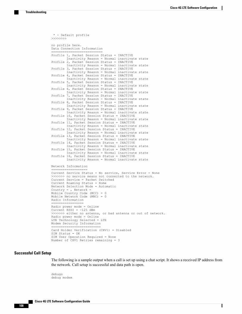
* - Default profile>>>>>>>>
no profile here.Data Connection Information===========================Profile 1, Packet Session Status = INACTIVE
Inactivity Reason = Normal inactivate stateProfile 2, Packet Session Status = INACTIVE
Inactivity Reason = Normal inactivate stateProfile 3, Packet Session Status = INACTIVE
Inactivity Reason = Normal inactivate stateProfile 4, Packet Session Status = INACTIVE
Inactivity Reason = Normal inactivate stateProfile 5, Packet Session Status = INACTIVE
Inactivity Reason = Normal inactivate stateProfile 6, Packet Session Status = INACTIVE
Inactivity Reason = Normal inactivate stateProfile 7, Packet Session Status = INACTIVE
Inactivity Reason = Normal inactivate stateProfile 8, Packet Session Status = INACTIVE
Inactivity Reason = Normal inactivate stateProfile 9, Packet Session Status = INACTIVE
Inactivity Reason = Normal inactivate stateProfile 10, Packet Session Status = INACTIVE
Inactivity Reason = Normal inactivate stateProfile 11, Packet Session Status = INACTIVE
Inactivity Reason = Normal inactivate stateProfile 12, Packet Session Status = INACTIVE
Inactivity Reason = Normal inactivate stateProfile 13, Packet Session Status = INACTIVE
Inactivity Reason = Normal inactivate stateProfile 14, Packet Session Status = INACTIVE
Inactivity Reason = Normal inactivate stateProfile 15, Packet Session Status = INACTIVE
Inactivity Reason = Normal inactivate stateProfile 16, Packet Session Status = INACTIVE
Inactivity Reason = Normal inactivate state
Network Information===================Current Service Status = No service, Service Error = None>>>>>>> no service means not connected to the network.Current Service = Packet SwitchedCurrent Roaming Status = HomeNetwork Selection Mode = AutomaticCountry = , Network =Mobile Country Code (MCC) = 0Mobile Network Code (MNC) = 0Radio Information=================Radio power mode = OnlineCurrent RSSI = -125 dBm>>>>>>> either no antenna, or bad antenna or out of network.Radio power mode = OnlineLTE Technology Selected = LTEModem Security Information==========================Card Holder Verification (CHV1) = DisabledSIM Status = OKSIM User Operation Required = NoneNumber of CHV1 Retries remaining = 3
Successful Call Setup
The following is a sample output when a call is set up using a chat script. It shows a received IP address fromthe network. Call setup is successful and data path is open.
debugsdebug modem
Cisco 4G LTE Software Configuration Guide108
Cisco 4G LTE Software ConfigurationTroubleshooting

debup chatDevice#Aug 25 18:46:59.604: CHAT0/0/0: Attempting async line dialer scriptAug 25 18:46:59.604: CHAT0/0/0: Dialing using Modem script: lte & System script: noneAug 25 18:46:59.604: CHAT0/0/0: process startedAug 25 18:46:59.604: CHAT0/0/0: Asserting DTRAug 25 18:46:59.604: CHAT0/0/0: Chat script lte startedAug 25 18:46:59.604: CHAT0/0/0: Sending string: AT!CALLAug 25 18:46:59.604: CHAT0/0/0: Expecting string: OKAug 25 18:47:00.641: CHAT0/0/0: Completed match for expect: OKAug 25 18:47:00.641: CHAT0/0/0: Chat script lte finished, status = SuccessAug 25 18:47:00.641: TTY0/0/0: no timer type 1 to destroyAug 25 18:47:00.641: TTY0/0/0: no timer type 0 to destroyAug 25 18:47:00.641: TTY0/0/0: no timer type 2 to destroyAug 25 18:47:02.642: %LINK-3-UPDOWN: Interface Cellular0/0/0, changed state to upAug 25 18:47:02.642: %DIALER-6-BIND: Interface Ce0/0/0 bound to profile Di1Aug 25 18:47:03.642: %LINEPROTO-5-UPDOWN: Line protocol on Interface Cellular0/0/0, changedstate to up (69.78.96.14) [OK]
Modem Troubleshooting Using Integrated Modem DM Logging
As part of the 3G and 4G serviceability enhancement in Cisco IOS Release 15.2(4)M2 and Cisco IOS Release15.3(1)T, DM log collection has been integrated into Cisco IOS, eliminating the need for an external PC andsimplifying the DM log collection process. The lte modem dm-log command can be used in controller cellularconfiguration mode to configure integrated DM logging to monitor traffic on the modem. See the Cisco 3Gand 4G Serviceability Enhancement User Guide for more information on configuring Integrated DMLoggingparameters.
Modem Settings for North America and Carriers Operating on 700 MHz Band
For HWIC-3G deployments in North America and for carriers operating in the 700 MHz band, the followingchanges to the modem settings are required to prevent long network attach times.
The output of show cellular x/x/x all command shows the following:
• Current RSSI is –125 dBM
• LTE Technology Preference = No preference specified (AUTO)
Changing Modem SettingsTo change the modem settings to force the modem to scan different technologies, use the following CiscoIOS command:
Device# cellular 0/0/0 lte technologyauto Automatic LTE Technology Selectioncdma-1xrtt CDMA 1xRTTcdma-evdo CDMA EVDO Rev Acdma-hybrid HYBRID CDMAgsm GSMlte LTEumts UMTS
Electronic Serial Number (ESN)The ESN number is located directly on the modem label in hexadecimal notation. It can also be retrievedusing the Cisco IOS CLI using the show cellular slot/port/hwic hardware command.
The sample output below shows the ESN number:
Hardware Information====================
Cisco 4G LTE Software Configuration Guide 109
Cisco 4G LTE Software ConfigurationTroubleshooting

Electronic Serial Number (ESN) = 0x603c9854 [09603971156]Electronic Serial Number (ESN) = <specific ESN in hexadecimal> [specific ESN in decimal]
Configuration Examples for 4G LTE
Example: Basic Cellular Interface Configuration: Cisco EHWIC-4G-LTEThe following example shows how to configure the cellular interface to be used as a primary and is configuredas the default route:
Device# show running-configchat-script lte "" "AT!CALL" TIMEOUT 20 "OK"interface Cellular0/0/0ip address negotiatedencapsulation slipdialer in-banddialer string ltedialer-group 1async mode interactiveip route 172.22.1.10 255.255.255.255 cellular 0/0/0dialer-list 1 protocol ip permitline 0/0/0script dialer ltemodem InOut
Example: Basic Cellular Interface Configuration: Cisco 819 4G LTE ISRThe following example shows how to configure the cellular interface to be used as primary and is configuredas the default route:
chat-script lte "" "AT!CALL1" TIMEOUT 20 "OK"!!controller Cellular 0!!interface Cellular0ip address negotiatedencapsulation slipload-interval 30dialer in-banddialer idle-timeout 0dialer string ltedialer-group 1no peer default ip addressasync mode interactiverouting dynamic!ip route 172.22.1.10 255.255.255.255 cellular 0/0/0!dialer-list 1 protocol ip permit!line 3script dialer ltemodem InOutno exectransport input alltransport output all!
Cisco 4G LTE Software Configuration Guide110
Cisco 4G LTE Software ConfigurationConfiguration Examples for 4G LTE
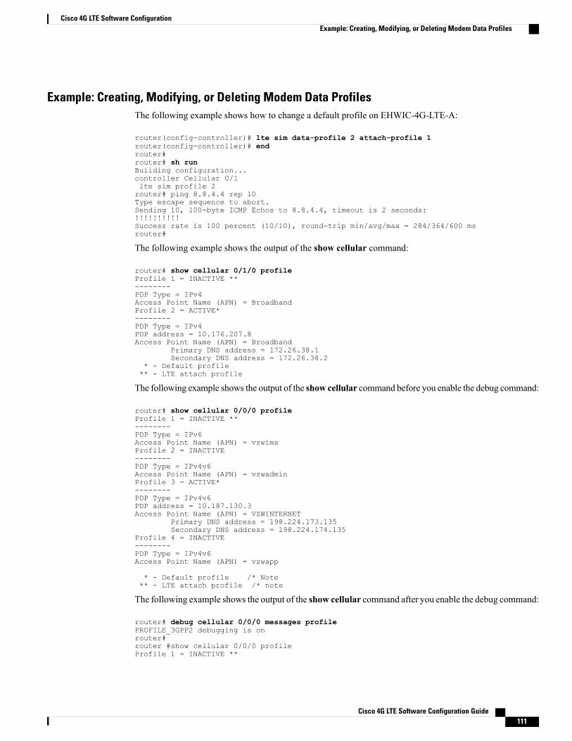
Example: Creating, Modifying, or Deleting Modem Data ProfilesThe following example shows how to change a default profile on EHWIC-4G-LTE-A:
router(config-controller)# lte sim data-profile 2 attach-profile 1router(config-controller)# endrouter#router# sh runBuilding configuration...controller Cellular 0/1lte sim profile 2router# ping 8.8.4.4 rep 10Type escape sequence to abort.Sending 10, 100-byte ICMP Echos to 8.8.4.4, timeout is 2 seconds:!!!!!!!!!!Success rate is 100 percent (10/10), round-trip min/avg/max = 284/364/600 msrouter#
The following example shows the output of the show cellular command:
router# show cellular 0/1/0 profileProfile 1 = INACTIVE **--------PDP Type = IPv4Access Point Name (APN) = BroadbandProfile 2 = ACTIVE*--------PDP Type = IPv4PDP address = 10.176.207.8Access Point Name (APN) = Broadband
Primary DNS address = 172.26.38.1Secondary DNS address = 172.26.38.2
* - Default profile** - LTE attach profile
The following example shows the output of the show cellular command before you enable the debug command:
router# show cellular 0/0/0 profileProfile 1 = INACTIVE **--------PDP Type = IPv6Access Point Name (APN) = vzwimsProfile 2 = INACTIVE--------PDP Type = IPv4v6Access Point Name (APN) = vzwadminProfile 3 = ACTIVE*--------PDP Type = IPv4v6PDP address = 10.187.130.3Access Point Name (APN) = VZWINTERNET
Primary DNS address = 198.224.173.135Secondary DNS address = 198.224.174.135
Profile 4 = INACTIVE--------PDP Type = IPv4v6Access Point Name (APN) = vzwapp
* - Default profile /* Note** - LTE attach profile /* note
The following example shows the output of the show cellular command after you enable the debug command:
router# debug cellular 0/0/0 messages profilePROFILE_3GPP2 debugging is onrouter#router #show cellular 0/0/0 profileProfile 1 = INACTIVE **
Cisco 4G LTE Software Configuration Guide 111
Cisco 4G LTE Software ConfigurationExample: Creating, Modifying, or Deleting Modem Data Profiles
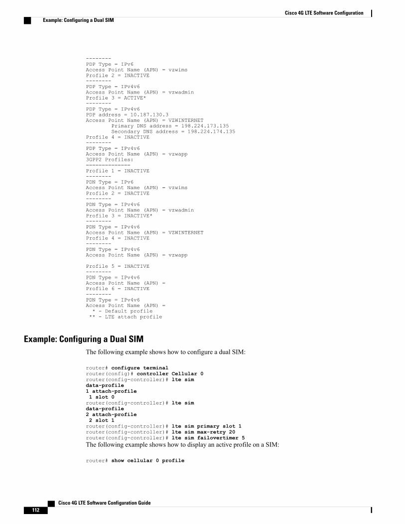
--------PDP Type = IPv6Access Point Name (APN) = vzwimsProfile 2 = INACTIVE--------PDP Type = IPv4v6Access Point Name (APN) = vzwadminProfile 3 = ACTIVE*--------PDP Type = IPv4v6PDP address = 10.187.130.3Access Point Name (APN) = VZWINTERNET
Primary DNS address = 198.224.173.135Secondary DNS address = 198.224.174.135
Profile 4 = INACTIVE--------PDP Type = IPv4v6Access Point Name (APN) = vzwapp3GPP2 Profiles:==============Profile 1 = INACTIVE--------PDN Type = IPv6Access Point Name (APN) = vzwimsProfile 2 = INACTIVE--------PDN Type = IPv4v6Access Point Name (APN) = vzwadminProfile 3 = INACTIVE*--------PDN Type = IPv4v6Access Point Name (APN) = VZWINTERNETProfile 4 = INACTIVE--------PDN Type = IPv4v6Access Point Name (APN) = vzwapp
Profile 5 = INACTIVE--------PDN Type = IPv4v6Access Point Name (APN) =Profile 6 = INACTIVE--------PDN Type = IPv4v6Access Point Name (APN) =* - Default profile** - LTE attach profile
Example: Configuring a Dual SIMThe following example shows how to configure a dual SIM:
router# configure terminalrouter(config)# controller Cellular 0router(config-controller)# lte simdata-profile1 attach-profile1 slot 0router(config-controller)# lte simdata-profile2 attach-profile2 slot 1router(config-controller)# lte sim primary slot 1router(config-controller)# lte sim max-retry 20router(config-controller)# lte sim failovertimer 5The following example shows how to display an active profile on a SIM:
router# show cellular 0 profile
Cisco 4G LTE Software Configuration Guide112
Cisco 4G LTE Software ConfigurationExample: Configuring a Dual SIM

Profile Information====================Profile 1 = INACTIVE--------PDP Type = IPv4Access Point Name (APN) = internet.telenor.seProfile 2 = ACTIVE* **--------PDP Type = IPv4PDP address = 78.78.16.214Access Point Name (APN) = telia.online.se
Primary DNS address = 195.67.199.18Secondary DNS address = 195.67.199.19
* - Default profile** - LTE attach profileConfigured default profile for active SIM 1 is profile 2.The following example shows how to display the status of a dual SIM:
router# show cellular 0 securityActive SIM = 0SIM switchover attempts = 0Card Holder Verification (CHV1) = DisabledSIM Status = OKSIM User Operation Required = NoneNumber of CHV1 Retries remaining = 3router#The following example shows how to display the status of a dual SIM:
router# show controller cellular 0Interface Cellular04G WWAN Modem - Global Multimode LTE/DC-HSPA+/HSPA+/HSPA/UMTS/EDGE/GPRSCellular modem configuration======================================Modem is recognized as validmanufacture id: 0x00001199 product id: 0x000068A2Power status: ActiveSierra Wireless Direct IP MC7710 modem::Cellular Dual SIM details:---------------------------SIM 0 is presentSIM 1 is presentSIM 0 is active SIM
Cellular Interface Configuration for Always-On Connection
Dialer-Watch Configuration without External Dialer Interface
The following example shows how to configure dialer-watch without external dialer interface. The bold textis used to indicate important commands that are specific to dialer-watch.
chat-script lte "" "AT!CALL" TIMEOUT 20 "OK"interface Cellular0/0/0ip address negotiatedencapsulation slipdialer in-banddialer string LTEdialer watch-group 1async mode interactive!dialer watch-list 1 ip 5.6.7.8 0.0.0.0dialer watch-list 1 delay route-check initial 60dialer watch-list 1 delay connect 1!
Cisco 4G LTE Software Configuration Guide 113
Cisco 4G LTE Software ConfigurationCellular Interface Configuration for Always-On Connection

ip route 0.0.0.0 0.0.0.0 cellular 0/0/0line 0/0/0script dialer LTEmodem InOutno exectransport input alltransport output all
Dialer-Persistent Configuration with External Dialer Interface
The following example shows how to configure dialer-persistent with external dialer interface. The bold textis used to indicate important commands that are specific to dialer-persistent.
chat-script lte "" "AT!CALL" TIMEOUT 20 "OK"interface Cellular0/0/0ip address negotiatedencapsulation slipdialer in-banddialer pool-member 1async mode interactiverouting dynamicinterface Dialer1ip address negotiatedencapsulation slipdialer pool 1dialer idle-timeout 0dialer string ltedialer persistentdialer-group 1!dialer-list 1 protocol ip permitip route 0.0.0.0 0.0.0.0 dialer 1line 0/0/0script dialer ltemodem InOutno exectransport input alltransport output all
Example: GRE Tunnel over Cellular Interface ConfigurationThe following example shows how to configure the static IP address when a GRE tunnel interface is configuredwith ip address unnumbered cellular interface:
The GRE tunnel configuration is supported only if the service providers provide a public IP address onthe LTE interface.
Note
For service providers using a private IP address, the point-to-point static GRE tunnel cannot be set upwith a private IP address at one end and a public IP address on the other end.
Note
interface Tunnel2ip unnumbered **internal LAN interface GE0/0 etc.**tunnel source Cellular0tunnel destination a.b.c.dinterface Cellular0ip address negotiatedencapsulation slipno ip mroute-cachedialer in-band
Cisco 4G LTE Software Configuration Guide114
Cisco 4G LTE Software ConfigurationExample: GRE Tunnel over Cellular Interface Configuration
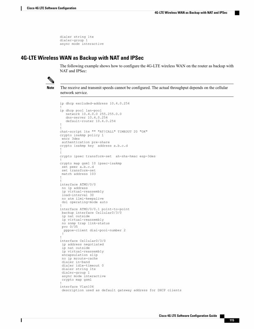
dialer string ltedialer-group 1async mode interactive
4G-LTE Wireless WAN as Backup with NAT and IPSecThe following example shows how to configure the 4G-LTE wireless WAN on the router as backup withNAT and IPSec:
The receive and transmit speeds cannot be configured. The actual throughput depends on the cellularnetwork service.
Note
ip dhcp excluded-address 10.4.0.254!ip dhcp pool lan-pool
network 10.4.0.0 255.255.0.0dns-server 10.4.0.254default-router 10.4.0.254
!!chat-script lte "" "AT!CALL" TIMEOUT 20 "OK"crypto isakmp policy 1encr 3desauthentication pre-sharecrypto isakmp key address a.b.c.d!!crypto ipsec transform-set ah-sha-hmac esp-3des!crypto map gsm1 10 ipsec-isakmpset peer a.b.c.dset transform-setmatch address 103!!interface ATM0/0/0no ip addressip virtual-reassemblyload-interval 30no atm ilmi-keepalivedsl operating-mode auto!interface ATM0/0/0.1 point-to-pointbackup interface Cellular0/3/0ip nat outsideip virtual-reassemblyno snmp trap link-statuspvc 0/35pppoe-client dial-pool-number 2!!interface Cellular0/3/0ip address negotiatedip nat outsideip virtual-reassemblyencapsulation slipno ip mroute-cachedialer in-banddialer idle-timeout 0dialer string ltedialer-group 1async mode interactivecrypto map gsm1!interface Vlan104description used as default gateway address for DHCP clients
Cisco 4G LTE Software Configuration Guide 115
Cisco 4G LTE Software Configuration4G-LTE Wireless WAN as Backup with NAT and IPSec

ip address 10.4.0.254 255.255.0.0ip nat insideip virtual-reassembly!interface Dialer2ip address negotiatedip mtu 1492ip nat outsideip virtual-reassemblyencapsulation pppload-interval 30dialer pool 2dialer-group 2ppp authentication chap callinppp chap hostname [email protected] chap password 0 ciscoppp ipcp dns requestcrypto map gsm1!ip local policy route-map track-primary-ifip route 0.0.0.0 0.0.0.0 Dialer2 track 234ip route 0.0.0.0 0.0.0.0 Cellular0/3/0 254!!ip nat inside source route-map nat2cell interface Cellular0/3/0 overloadip nat inside source route-map nat2dsl interface Dialer2 overload!ip sla 1icmp-echo 2.2.2.2 source-interface Dialer2timeout 1000frequency 2ip sla schedule 1 life forever start-time nowaccess-list 1 permit anyaccess-list 101 deny ip 10.4.0.0 0.0.255.255 10.0.0.0 0.255.255.255access-list 101 permit ip 10.4.0.0 0.0.255.255 anyaccess-list 102 permit icmp any host 2.2.2.2access-list 103 permit ip 10.4.0.0 0.0.255.255 10.0.0.0 0.255.255.255dialer-list 1 protocol ip list 1dialer-list 2 protocol ip permit!!route-map track-primary-if permit 10match ip address 102set interface Dialer2!route-map nat2dsl permit 10match ip address 101match interface Dialer2!route-map nat2cell permit 10match ip address 101match interface Cellular0/3/0!line 0/3/0exec-timeout 0 0script dialer lteloginmodem InOut
For service providers using a private IP address, use the crypto ipsec transform-set esp command (thatis, esp-aes esp-sha256-hmac...).
Note
Cisco 4G LTE Software Configuration Guide116
Cisco 4G LTE Software Configuration4G-LTE Wireless WAN as Backup with NAT and IPSec

SIM Configuration: Examples
Locking the SIM Card: Example
The following example shows how to lock the SIM. The italicized text in this configuration example is usedto indicate comments and are not be seen when a normal console output is viewed.
Device# sh cellular 0/0/0 securityCard Holder Verification (CHV1) = DisabledSIM Status = OKSIM User Operation Required = NoneNumber of CHV1 Retries remaining = 3Device#!! SIM is in unlocked state.!Device# cellular 0/0/0 lte sim lock 1111!!!WARNING: SIM will be locked with pin=1111(4).Do not enter new PIN to lock SIM. Enter PIN that the SIM is configured with.Call will be disconnected!!!Are you sure you want to proceed?[confirm]Device#Apr 26 19:35:28.339: %CELLWAN-2-MODEM_DOWN: Modem in HWIC slot 0/0 is DOWNApr 26 19:35:59.967: %CELLWAN-2-MODEM_UP: Modem in HWIC slot 0/0 is now UPDevice#Device# sh cellular 0/0/0 securityCard Holder Verification (CHV1) = EnabledSIM Status = LockedSIM User Operation Required = Enter CHV1Number of CHV1 Retries remaining = 3Device#!! SIM is in locked state.!
Unlocking the SIM Card: Example
The following example shows how to unlock the SIM. The italicized text throughout this configuration exampleis used to indicate comments and will not be seen when a normal console output is viewed.
Device# sh cellular 0/0/0 securityCard Holder Verification (CHV1) = EnabledSIM Status = LockedSIM User Operation Required = Enter CHV1Number of CHV1 Retries remaining = 3Device#!! SIM is in locked state.!Device# cellular 0/0/0 lte sim unlock 1111!!!WARNING: SIM will be unlocked with pin=1111(4).Do not enter new PIN to unlock SIM. Enter PIN that the SIM is configured with.Call will be disconnected!!!Are you sure you want to proceed?[confirm]Device#Device# sh cellular 0/0/0 securityCard Holder Verification (CHV1) = DisabledSIM Status = OKSIM User Operation Required = NoneNumber of CHV1 Retries remaining = 3Device#!! SIM is in unlocked state.!
Automatic SIM Authentication: Example
The following example shows how to configure automatic SIM authentication. The italicized text throughoutthis configuration example is used to indicate comments and will not be seen when a normal console outputis viewed.
Device# show cellular 0/0/0 securityCard Holder Verification (CHV1) = Disabled
Cisco 4G LTE Software Configuration Guide 117
Cisco 4G LTE Software ConfigurationSIM Configuration: Examples

SIM Status = OKSIM User Operation Required = NoneNumber of CHV1 Retries remaining = 3Device#!! SIM is in unlocked state.!Device# cellular 0/0/0 lte sim lock 1111!!!WARNING: SIM will be locked with pin=1111(4).Do not enter new PIN to lock SIM. Enter PIN that the SIM is configured with.Call will be disconnected!!!Are you sure you want to proceed?[confirm]Device#Apr 26 21:22:34.555: %CELLWAN-2-MODEM_DOWN: Modem in HWIC slot 0/0 is DOWNApr 26 21:23:06.495: %CELLWAN-2-MODEM_UP: Modem in HWIC slot 0/0 is now UPDevice#Device# sh cellular 0/0/0 securityCard Holder Verification (CHV1) = EnabledSIM Status = LockedSIM User Operation Required = Enter CHV1Number of CHV1 Retries remaining = 3Device#!! SIM is in locked state. SIM needs to be in locked state for SIM authentication to !work.!Device#Device# conf termEnter configuration commands, one per line. End with CNTL/Z.Device(config)# controller cellular 0/0Device(config-controller)# lte sim authenticate 0 1111CHV1 configured and sent to modem for verificationDevice(config-controller)# endDevice#Apr 26 21:23:50.571: %SYS-5-CONFIG_I: Configured from console by consoleDevice#Device# sh cellular 0/0/0 securityCard Holder Verification (CHV1) = EnabledSIM Status = OKSIM User Operation Required = NoneNumber of CHV1 Retries remaining = 3Device#!! SIM is now in locked state but it can be used for connectivity since authentication is !good. Authentication can be saved in the router configuration so that when you boot up ! the routerwith the same locked SIM, connection can be established with the correct ! Cisco IOS configuration.!
Changing the PIN Code: Example
The following example shows how to change the assigned PIN code. The italicized text throughout thisconfiguration example is used to indicate comments and will not be seen when a normal console output isviewed.
Device# sh cellular 0/0/0 securityCard Holder Verification (CHV1) = DisabledSIM Status = OKSIM User Operation Required = NoneNumber of CHV1 Retries remaining = 3Device#!! SIM is in unlocked state.!Device#Device# cellular 0/0/0 lte sim lock 1111!!!WARNING: SIM will be locked with pin=1111(4).Do not enter new PIN to lock SIM. Enter PIN that the SIM is configured with.Call will be disconnected!!!Are you sure you want to proceed?[confirm]Device#Apr 26 21:58:11.903: %CELLWAN-2-MODEM_DOWN: Modem in HWIC slot 0/0 is DOWNApr 26 21:58:43.775: %CELLWAN-2-MODEM_UP: Modem in HWIC slot 0/0 is now UPDevice#Device# sh cellular 0/0/0 securityCard Holder Verification (CHV1) = EnabledSIM Status = LockedSIM User Operation Required = Enter CHV1Number of CHV1 Retries remaining = 3Device#!! SIM is in locked state. SIM needs to be in locked state to change its PIN.!Device#Device# cellular 0/0/0 lte sim change-pin 1111 0000!!!WARNING: SIM PIN will be changed from:1111(4) to:0000(4)Call will be disconnected. If old PIN is entered incorrectly in 3 attempt(s), SIM will be
Cisco 4G LTE Software Configuration Guide118
Cisco 4G LTE Software ConfigurationSIM Configuration: Examples
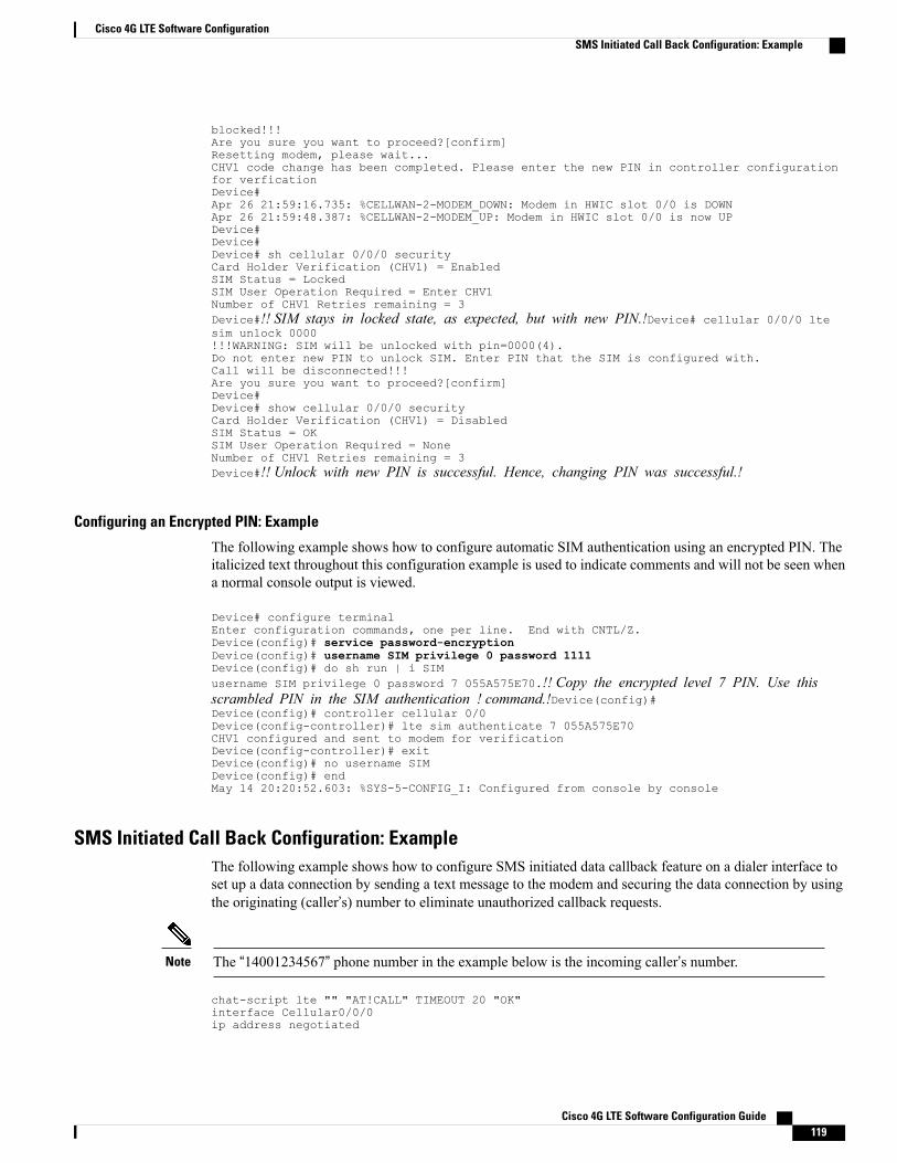
blocked!!!Are you sure you want to proceed?[confirm]Resetting modem, please wait...CHV1 code change has been completed. Please enter the new PIN in controller configurationfor verficationDevice#Apr 26 21:59:16.735: %CELLWAN-2-MODEM_DOWN: Modem in HWIC slot 0/0 is DOWNApr 26 21:59:48.387: %CELLWAN-2-MODEM_UP: Modem in HWIC slot 0/0 is now UPDevice#Device#Device# sh cellular 0/0/0 securityCard Holder Verification (CHV1) = EnabledSIM Status = LockedSIM User Operation Required = Enter CHV1Number of CHV1 Retries remaining = 3Device#!! SIM stays in locked state, as expected, but with new PIN.!Device# cellular 0/0/0 ltesim unlock 0000!!!WARNING: SIM will be unlocked with pin=0000(4).Do not enter new PIN to unlock SIM. Enter PIN that the SIM is configured with.Call will be disconnected!!!Are you sure you want to proceed?[confirm]Device#Device# show cellular 0/0/0 securityCard Holder Verification (CHV1) = DisabledSIM Status = OKSIM User Operation Required = NoneNumber of CHV1 Retries remaining = 3Device#!! Unlock with new PIN is successful. Hence, changing PIN was successful.!
Configuring an Encrypted PIN: Example
The following example shows how to configure automatic SIM authentication using an encrypted PIN. Theitalicized text throughout this configuration example is used to indicate comments and will not be seen whena normal console output is viewed.
Device# configure terminalEnter configuration commands, one per line. End with CNTL/Z.Device(config)# service password-encryptionDevice(config)# username SIM privilege 0 password 1111Device(config)# do sh run | i SIMusername SIM privilege 0 password 7 055A575E70.!! Copy the encrypted level 7 PIN. Use thisscrambled PIN in the SIM authentication ! command.!Device(config)#Device(config)# controller cellular 0/0Device(config-controller)# lte sim authenticate 7 055A575E70CHV1 configured and sent to modem for verificationDevice(config-controller)# exitDevice(config)# no username SIMDevice(config)# endMay 14 20:20:52.603: %SYS-5-CONFIG_I: Configured from console by console
SMS Initiated Call Back Configuration: ExampleThe following example shows how to configure SMS initiated data callback feature on a dialer interface toset up a data connection by sending a text message to the modem and securing the data connection by usingthe originating (caller’s) number to eliminate unauthorized callback requests.
The “14001234567” phone number in the example below is the incoming caller’s number.Note
chat-script lte "" "AT!CALL" TIMEOUT 20 "OK"interface Cellular0/0/0ip address negotiated
Cisco 4G LTE Software Configuration Guide 119
Cisco 4G LTE Software ConfigurationSMS Initiated Call Back Configuration: Example
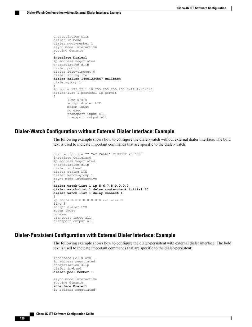
encapsulation slipdialer in-banddialer pool-member 1async mode interactiverouting dynamic!interface Dialer1ip address negotiatedencapsulation slipdialer pool 1dialer idle-timeout 0dialer string ltedialer caller 14001234567 callbackdialer-group 1!ip route 172.22.1.10 255.255.255.255 Cellular0/0/0dialer-list 1 protocol ip permit!
line 0/0/0script dialer LTEmodem InOutno exectransport input alltransport output all
Dialer-Watch Configuration without External Dialer Interface: ExampleThe following example shows how to configure the dialer-watch without external dialer interface. The boldtext is used to indicate important commands that are specific to the dialer-watch:
chat-script lte "" "AT!CALL1" TIMEOUT 20 "OK"interface Cellular0ip address negotiatedencapsulation slipdialer in-banddialer string LTEdialer watch-group 1async mode interactive!dialer watch-list 1 ip 5.6.7.8 0.0.0.0dialer watch-list 1 delay route-check initial 60dialer watch-list 1 delay connect 1!ip route 0.0.0.0 0.0.0.0 cellular 0line 3script dialer LTEmodem InOutno exectransport input alltransport output all
Dialer-Persistent Configuration with External Dialer Interface: ExampleThe following example shows how to configure the dialer-persistent with external dialer interface. The boldtext is used to indicate important commands that are specific to the dialer-persistent:
interface Cellular0ip address negotiatedencapsulation slipdialer in-banddialer pool-member 1
async mode interactiverouting dynamicinterface Dialer1ip address negotiated
Cisco 4G LTE Software Configuration Guide120
Cisco 4G LTE Software ConfigurationDialer-Watch Configuration without External Dialer Interface: Example

encapsulation slipdialer pool 1dialer idle-timeout 0dialer string ltedialer persistentdialer-group 1!dialer-list 1 protocol ip permitip route 0.0.0.0 0.0.0.0 dialer 1line 3script dialer ltemodem InOutno exectransport input alltransport output all
Example: Configuring Multiple PDNThe following example shows how to configure multiple PDN:
chat-script lte "" "AT!CALL" TIMEOUT 20 "OK"!interface Cellular0ip address negotiatedencapsulation slipdialer in-banddialer idle-timeout 0dialer string ltedialer-group 1no peer default ip addressasync mode interactiverouting dynamic!interface Cellular1ip address negotiatedencapsulation slipdialer in-banddialer idle-timeout 0dialer string ltedialer-group 1!ip route 141.141.141.141 255.255.255.255 Cellular1ip route 192.169.187.254 255.255.255.255 Cellular0!line 3exec-timeout 0 0 script dialer ltemodem InOutno exectransport input alltransport output allrxspeed 100000000txspeed 50000000!line 8script dialer ltemodem InOutno exectransport input alltransport output allrxspeed 100000000txspeed 50000000The following show commands can be used to verify the status of the multiple PDN calls:
C800-router#sh cellular 0 profileProfile 1 = ACTIVE* **--------PDP Type = IPv4PDP address = 21.21.21.204Access Point Name (APN) = basic
Cisco 4G LTE Software Configuration Guide 121
Cisco 4G LTE Software ConfigurationExample: Configuring Multiple PDN

Authentication = NonePrimary DNS address = 171.70.168.183Secondary DNS address = 173.36.131.10Profile 2 = ACTIVE--------PDP Type = IPv4PDP address = 22.22.22.111Access Point Name (APN) = mpdnAuthentication = NonePrimary DNS address = 171.70.168.183Secondary DNS address = 173.36.131.10Profile 3 = INACTIVE--------PDP Type = IPv4Access Point Name (APN) = aaaauthAuthentication = NoneProfile 4 = INACTIVE--------PDP Type = IPv4Access Point Name (APN) = basic2Authentication = None* - Default profile** - LTE attach profileConfigured default profile for active SIM 0 is profile 1.C800-router#sh cellular 0 connectionProfile 1, Packet Session Status = ACTIVECellular0:Data Transmitted = 600 bytes, Received = 500 bytesIP address = 21.21.21.204Primary DNS address = 171.70.168.183Secondary DNS address = 173.36.131.10Profile 2, Packet Session Status = ACTIVECellular1:Data Transmitted = 1800 bytes, Received = 1800 bytesIP address = 22.22.22.111Primary DNS address = 171.70.168.183Secondary DNS address = 173.36.131.10Profile 3, Packet Session Status = INACTIVEProfile 4, Packet Session Status = INACTIVEProfile 5, Packet Session Status = INACTIVEProfile 6, Packet Session Status = INACTIVEProfile 7, Packet Session Status = INACTIVEProfile 8, Packet Session Status = INACTIVEProfile 9, Packet Session Status = INACTIVEProfile 10, Packet Session Status = INACTIVEProfile 11, Packet Session Status = INACTIVEProfile 12, Packet Session Status = INACTIVEProfile 13, Packet Session Status = INACTIVEProfile 14, Packet Session Status = INACTIVEProfile 15, Packet Session Status = INACTIVEProfile 16, Packet Session Status = INACTIVEC800-router#sh ip interface briefInterface IP-Address OK? Method Status ProtocolCellular0 21.21.21.204 YES IPCP up upCellular1 22.22.22.111 YES IPCP up upFastEthernet0 unassigned YES unset up upFastEthernet1 unassigned YES unset down downFastEthernet2 unassigned YES unset down downFastEthernet3 unassigned YES unset down downGigabitEthernet0 unassigned YES NVRAM down downLoopback0 1.1.1.1 YES NVRAM up upSerial0 unassigned YES NVRAM administratively down downVlan1 5.13.1.22 YES NVRAM up upVlan2 72.119.152.9 YES NVRAM down down
C800-router#show ip dns viewDNS View default parameters:Logging is offDNS Resolver settings:Domain lookup is disabledDefault domain name:Domain search list:Lookup timeout: 3 secondsLookup retries: 2
Cisco 4G LTE Software Configuration Guide122
Cisco 4G LTE Software ConfigurationExample: Configuring Multiple PDN
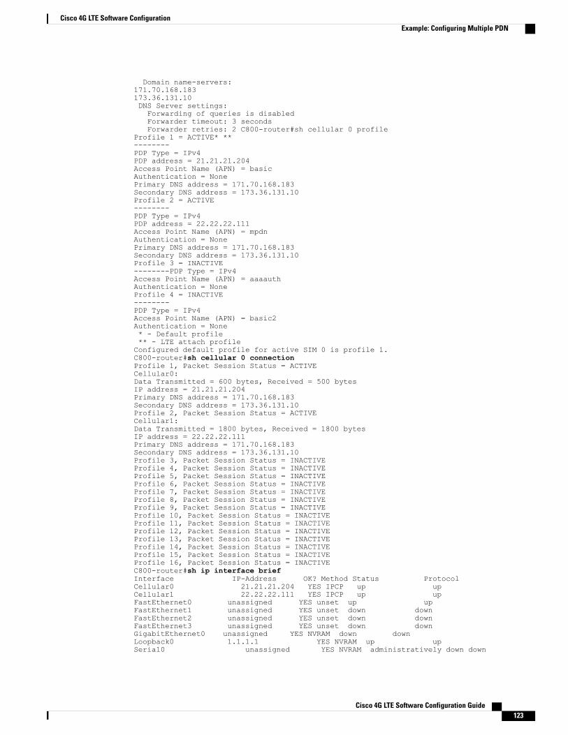
Domain name-servers:171.70.168.183173.36.131.10DNS Server settings:Forwarding of queries is disabledForwarder timeout: 3 secondsForwarder retries: 2 C800-router#sh cellular 0 profile
Profile 1 = ACTIVE* **--------PDP Type = IPv4PDP address = 21.21.21.204Access Point Name (APN) = basicAuthentication = NonePrimary DNS address = 171.70.168.183Secondary DNS address = 173.36.131.10Profile 2 = ACTIVE--------PDP Type = IPv4PDP address = 22.22.22.111Access Point Name (APN) = mpdnAuthentication = NonePrimary DNS address = 171.70.168.183Secondary DNS address = 173.36.131.10Profile 3 = INACTIVE--------PDP Type = IPv4Access Point Name (APN) = aaaauthAuthentication = NoneProfile 4 = INACTIVE--------PDP Type = IPv4Access Point Name (APN) = basic2Authentication = None* - Default profile** - LTE attach profileConfigured default profile for active SIM 0 is profile 1.C800-router#sh cellular 0 connectionProfile 1, Packet Session Status = ACTIVECellular0:Data Transmitted = 600 bytes, Received = 500 bytesIP address = 21.21.21.204Primary DNS address = 171.70.168.183Secondary DNS address = 173.36.131.10Profile 2, Packet Session Status = ACTIVECellular1:Data Transmitted = 1800 bytes, Received = 1800 bytesIP address = 22.22.22.111Primary DNS address = 171.70.168.183Secondary DNS address = 173.36.131.10Profile 3, Packet Session Status = INACTIVEProfile 4, Packet Session Status = INACTIVEProfile 5, Packet Session Status = INACTIVEProfile 6, Packet Session Status = INACTIVEProfile 7, Packet Session Status = INACTIVEProfile 8, Packet Session Status = INACTIVEProfile 9, Packet Session Status = INACTIVEProfile 10, Packet Session Status = INACTIVEProfile 11, Packet Session Status = INACTIVEProfile 12, Packet Session Status = INACTIVEProfile 13, Packet Session Status = INACTIVEProfile 14, Packet Session Status = INACTIVEProfile 15, Packet Session Status = INACTIVEProfile 16, Packet Session Status = INACTIVEC800-router#sh ip interface briefInterface IP-Address OK? Method Status ProtocolCellular0 21.21.21.204 YES IPCP up upCellular1 22.22.22.111 YES IPCP up upFastEthernet0 unassigned YES unset up upFastEthernet1 unassigned YES unset down downFastEthernet2 unassigned YES unset down downFastEthernet3 unassigned YES unset down downGigabitEthernet0 unassigned YES NVRAM down downLoopback0 1.1.1.1 YES NVRAM up upSerial0 unassigned YES NVRAM administratively down down
Cisco 4G LTE Software Configuration Guide 123
Cisco 4G LTE Software ConfigurationExample: Configuring Multiple PDN
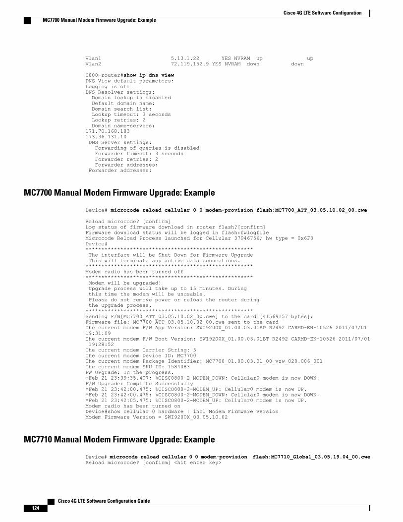
Vlan1 5.13.1.22 YES NVRAM up upVlan2 72.119.152.9 YES NVRAM down down
C800-router#show ip dns viewDNS View default parameters:Logging is offDNS Resolver settings:Domain lookup is disabledDefault domain name:Domain search list:Lookup timeout: 3 secondsLookup retries: 2Domain name-servers:
171.70.168.183173.36.131.10DNS Server settings:Forwarding of queries is disabledForwarder timeout: 3 secondsForwarder retries: 2Forwarder addresses:
Forwarder addresses:
MC7700 Manual Modem Firmware Upgrade: Example
Device# microcode reload cellular 0 0 modem-provision flash:MC7700_ATT_03.05.10.02_00.cwe
Reload microcode? [confirm]Log status of firmware download in router flash?[confirm]Firmware download status will be logged in flash:fwlogfileMicrocode Reload Process launched for Cellular 37946756; hw type = 0x6F3Device#*****************************************************The interface will be Shut Down for Firmware UpgradeThis will terminate any active data connections.*****************************************************Modem radio has been turned off*****************************************************Modem will be upgraded!Upgrade process will take up to 15 minutes. Duringthis time the modem will be unusable.Please do not remove power or reload the router duringthe upgrade process.*****************************************************Sending F/W[MC7700_ATT_03.05.10.02_00.cwe] to the card [41569157 bytes]:Firmware file: MC7700_ATT_03.05.10.02_00.cwe sent to the cardThe current modem F/W App Version: SWI9200X_01.00.03.01AP R2492 CARMD-EN-10526 2011/07/0119:31:09The current modem F/W Boot Version: SWI9200X_01.00.03.01BT R2492 CARMD-EN-10526 2011/07/0119:28:52The current modem Carrier String: 5The current modem Device ID: MC7700The current modem Package Identifier: MC7700_01.00.03.01_00_vzw_020.006_001The current modem SKU ID: 1584083FW UPgrade: In the progress.*Feb 21 23:39:35.407: %CISCO800-2-MODEM_DOWN: Cellular0 modem is now DOWN.F/W Upgrade: Complete Successfully*Feb 21 23:42:00.475: %CISCO800-2-MODEM_UP: Cellular0 modem is now UP.*Feb 21 23:42:00.475: %CISCO800-2-MODEM_DOWN: Cellular0 modem is now DOWN.*Feb 21 23:42:05.475: %CISCO800-2-MODEM_UP: Cellular0 modem is now UP.Modem radio has been turned onDevice#show cellular 0 hardware | incl Modem Firmware VersionModem Firmware Version = SWI9200X_03.05.10.02
MC7710 Manual Modem Firmware Upgrade: Example
Device# microcode reload cellular 0 0 modem-provision flash:MC7710_Global_03.05.19.04_00.cweReload microcode? [confirm] <hit enter key>
Cisco 4G LTE Software Configuration Guide124
Cisco 4G LTE Software ConfigurationMC7700 Manual Modem Firmware Upgrade: Example

Log status of firmware download in router flash?[confirm] <hit enter key>Firmware download status will be logged in flash:fwlogfileMicrocode Reload Process launched for Cellular 37946756; hw type = 0x6F3Device#*****************************************************The interface will be Shut Down for Firmware UpgradeThis will terminate any active data connections.*****************************************************Modem radio has been turned off*****************************************************Modem will be upgraded!Upgrade process will take up to 15 minutes. Duringthis time the modem will be unusable.Please do not remove power or reload the router duringthe upgrade process.*****************************************************Sending F/W[MC7710_Global_03.05.19.04_00.cwe] to the card [41569157 bytes]:Firmware file: MC7710_Global_03.05.19.04_00.cwe sent to the cardThe current modem F/W App Version: SWI9200X_03.00.11.00AP R2492 CARMD-EN-10526 2011/07/0119:31:09The current modem F/W Boot Version: SWI9200X_03.00.11.00BT R2492 CARMD-EN-10526 2011/07/0119:28:52The current modem Carrier String: 5The current modem Device ID: MC7710The current modem Package Identifier: MC7710_03.00.11.00_00_vzw_020.006_001The current modem SKU ID: 1584083FW UPgrade: In the progress.*Feb 21 23:39:35.407: %CISCO800-2-MODEM_DOWN: Cellular0 modem is now DOWN.F/W Upgrade: Complete Successfully*Feb 21 23:42:00.475: %CISCO800-2-MODEM_UP: Cellular0 modem is now UP.*Feb 21 23:42:00.475: %CISCO800-2-MODEM_DOWN: Cellular0 modem is now DOWN.*Feb 21 23:42:05.475: %CISCO800-2-MODEM_UP: Cellular0 modem is now UP.Modem radio has been turned onDevice# show cellular 0 hardware | incl Modem Firmware VersionModem Firmware Version = SWI9200X_03.05.19.04
MC7750 Manual Modem Firmware Upgrade: Example
Device# microcode reload cellular 0 0 modem-provision flash:MC7750_VZW_03.05.10.06_00.cwe
Reload microcode? [confirm] <hit enter key>Log status of firmware download in router flash?[confirm] <hit enter key>Firmware download status will be logged in flash:fwlogfileMicrocode Reload Process launched for Cellular 37946756; hw type = 0x6F3Device#*****************************************************The interface will be Shut Down for Firmware UpgradeThis will terminate any active data connections.*****************************************************Modem radio has been turned off*****************************************************Modem will be upgraded!Upgrade process will take up to 15 minutes. Duringthis time the modem will be unusable.Please do not remove power or reload the router duringthe upgrade process.*****************************************************Sending F/W[MC7750_VZW_03.05.10.06_00.cwe] to the card [41569157 bytes]:Firmware file: MC7750_VZW_03.05.10.06_00.cwe sent to the cardThe current modem F/W App Version: SWI9600M_01.00.09.03AP R2492 CARMD-EN-10526 2011/07/0119:31:09The current modem F/W Boot Version: SWI9600M_01.00.09.03BT R2492 CARMD-EN-10526 2011/07/0119:28:52The current modem Carrier String: 5The current modem Device ID: MC7750The current modem Package Identifier: MC7750_01.00.09.03_00_vzw_020.006_001The current modem SKU ID: 1584083FW UPgrade: In the progress.*Feb 21 23:39:35.407: %CISCO800-2-MODEM_DOWN: Cellular0 modem is now DOWN.F/W Upgrade: Complete Successfully
Cisco 4G LTE Software Configuration Guide 125
Cisco 4G LTE Software ConfigurationMC7750 Manual Modem Firmware Upgrade: Example

*Feb 21 23:42:00.475: %CISCO800-2-MODEM_UP: Cellular0 modem is now UP.*Feb 21 23:42:00.475: %CISCO800-2-MODEM_DOWN: Cellular0 modem is now DOWN.*Feb 21 23:42:05.475: %CISCO800-2-MODEM_UP: Cellular0 modem is now UP.Modem radio has been turned onDevice#show cellular 0 hardware | incl Modem Firmware VersionModem Firmware Version = SWI9600M_03.05.10.06
EEM Script 1 for MC7700 Modem
event manager applet FW authorization bypassevent none maxrun 1200action 1.0 if $_none_argc ne "1"action 1.0.1 syslog msg "Incorrect number of arguments passed. Please check and try again"action 1.0.2 exitaction 1.0.3 endaction 1.1 cli command "enable"action 1.2 set slot_number "$_none_arg1"action 1.3 cli command "show version | incl System image file"action 1.3.1 regexp "(.*)c(.*)-universalk9-(.*)\"" "$_cli_result" _match _sub1 _sub2 _sub3action 1.3.2 set platform "$_sub2"action 1.3.3 set current_IOS "c$_sub2-universalk9-$_sub3"action 1.3.4 set old_IOS "c$platform-universalk9-mz.SPA.152-4.M2"action 1.3.5 set new_IOS "c$platform-universalk9-mz.SPA.152-4.M3"action 1.3.6 set firmware "MC7700_ATT_03.05.10.02_00.cwe"action 1.3.7 set old_firmware "SWI9200X_01.00.03.01"action 1.3.8 set new_firmware "SWI9200X_03.05.10.02"action 1.4 if $platform eq "800"action 1.4.1 set cellular_interface 0action 1.5 elseaction 1.5.1 set cellular_interface "0/$slot_number/0"action 1.5.2 endaction 1.6 cli command "show cellular $cellular_interface hardware | incl Modem FirmwareVersion"action 1.7 string first "$new_firmware" "$_cli_result"action 1.8 if $_string_result ge 0action 1.8.1 syslog msg "Modem is already on new firmware $new_firmware. Exiting upgrade!!"action 1.8.2 exitaction 1.8.3 endaction 2.1 if $current_IOS ne $old_IOSaction 2.1.1 syslog msg "Current IOS version is incorrect. Please run $old_IOS beforestarting upgrade. Exiting upgrade!!"action 2.1.2 exitaction 2.2 endaction 2.3 cli command "show flash: | incl $new_IOS"action 3.0 string first "$new_IOS" "$_cli_result"action 3.1 if $_string_result lt 0action 3.1.1 syslog msg "$new_IOS is not present in flash. Exiting upgrade!!"action 3.1.2 exitaction 3.2 endaction 3.3 cli command "show flash: | incl $firmware"action 5.0 string first "$firmware" "$_cli_result"action 5.1 if $_string_result lt 0action 5.1.1 syslog msg "$firmware is not present in flash. Exiting upgrade!!"action 5.1.2 exitaction 5.2 endaction 5.3 cli command "configure terminal"action 5.4 cli command "no boot system"action 5.5 cli command "end"action 6.1 cli command "microcode reload cellular 0 $slot_number modem-provisionflash:$firmware" pattern "confirm"action 6.2 cli command "y"action 6.3 wait 400action 6.4 cli command "event manager run router_reload $old_IOS $new_IOS $old_firmware$cellular_interface"action 6.5 wait 120action 6.6 exit
Cisco 4G LTE Software Configuration Guide126
Cisco 4G LTE Software ConfigurationEEM Script 1 for MC7700 Modem

EEM Script 2 for MC7700 Modem
event manager applet router_reload authorization bypassevent none maxrun 120action 1.0 set old_IOS "$_none_arg1"action 1.1 set new_IOS "$_none_arg2"action 1.2 set old_firmware "$_none_arg3"action 1.3 set cellular_interface "$_none_arg4"action 1.4 cli command "enable"action 2.0 cli command "show cellular $cellular_interface hardware | inc Modem FirmwareVersion"action 2.1 set _string_result "0"action 2.2 string first "$old_firmware" "$_cli_result"action 2.3 if $_string_result ge "0"action 2.3.1 set boot_IOS "$old_IOS"action 2.3.2 syslog msg "Firmware did not Upgrade successfully. Please try again afterreload"action 2.4 elseaction 2.4.1 set boot_IOS "$new_IOS"action 2.4.2 syslog msg "Firmware upgraded successfully. value= $_string_result"action 2.4.3 endaction 2.5 cli command "configure terminal"action 2.5.1 cli command "boot system flash:$boot_IOS"action 2.5.2 cli command "config-register 0x2102"action 2.5.3 cli command "interface cellular $cellular_interface"action 2.5.4 cli command "no shut"action 2.5.5 cli command "end"action 2.5.6 cli command "write memory"action 2.5.7 reload
EEM Script 1 for MC7710 Modem
event manager applet FW authorization bypassevent none maxrun 1200action 1.0 if $_none_argc ne "1"action 1.0.1 syslog msg "Incorrect number of arguments passed. Please check and try again"action 1.0.2 exitaction 1.0.3 endaction 1.1 cli command "enable"action 1.2 set slot_number "$_none_arg1"action 1.3 cli command "show version | incl System image file"action 1.3.1 regexp "(.*)c(.*)-universalk9-(.*)\"" "$_cli_result" _match _sub1 _sub2 _sub3action 1.3.2 set platform "$_sub2"action 1.3.3 set current_IOS "c$_sub2-universalk9-$_sub3"action 1.3.4 set old_IOS "c$platform-universalk9-mz.SPA.152-4.M2"action 1.3.5 set new_IOS "c$platform-universalk9-mz.SPA.152-4.M3"action 1.3.6 set firmware "MC7710_Global_03.05.19.04_00.cwe"action 1.3.7 set old_firmware "SWI9200X_03.00.11.00"action 1.3.8 set new_firmware "SWI9200X_03.05.19.04"action 1.4 if $platform eq "800"action 1.4.1 set cellular_interface 0action 1.5 elseaction 1.5.1 set cellular_interface "0/$slot_number/0"action 1.5.2 endaction 1.6 cli command "show cellular $cellular_interface hardware | incl Modem FirmwareVersion"action 1.7 string first "$new_firmware" "$_cli_result"action 1.8 if $_string_result ge 0action 1.8.1 syslog msg "Modem is already on new firmware $new_firmware. Exiting upgrade!!"action 1.8.2 exitaction 1.8.3 endaction 2.1 if $current_IOS ne $old_IOSaction 2.1.1 syslog msg "Current IOS version is incorrect. Please run $old_IOS beforestarting upgrade. Exiting upgrade!!"action 2.1.2 exitaction 2.2 endaction 2.3 cli command "show flash: | incl $new_IOS"
Cisco 4G LTE Software Configuration Guide 127
Cisco 4G LTE Software ConfigurationEEM Script 2 for MC7700 Modem

action 3.0 string first "$new_IOS" "$_cli_result"action 3.1 if $_string_result lt 0action 3.1.1 syslog msg "$new_IOS is not present in flash. Exiting upgrade!!"action 3.1.2 exitaction 3.2 endaction 3.3 cli command "show flash: | incl $firmware"action 5.0 string first "$firmware" "$_cli_result"action 5.1 if $_string_result lt 0action 5.1.1 syslog msg "$firmware is not present in flash. Exiting upgrade!!"action 5.1.2 exitaction 5.2 endaction 5.3 cli command "configure terminal"action 5.4 cli command "no boot system"action 5.5 cli command "end"action 6.1 cli command "microcode reload cellular 0 $slot_number modem-provisionflash:$firmware" pattern "confirm"action 6.2 cli command "y"action 6.3 wait 400action 6.4 cli command "event manager run router_reload $old_IOS $new_IOS $old_firmware$cellular_interface"action 6.5 wait 120action 6.6 exit
EEM Script 2 for MC7710 Modem
event manager applet router_reload authorization bypassevent none maxrun 120action 1.0 set old_IOS "$_none_arg1"action 1.1 set new_IOS "$_none_arg2"action 1.2 set old_firmware "$_none_arg3"action 1.3 set cellular_interface "$_none_arg4"action 1.4 cli command "enable"action 2.0 cli command "show cellular $cellular_interface hardware | inc Modem FirmwareVersion"action 2.1 set _string_result "0"action 2.2 string first "$old_firmware" "$_cli_result"action 2.3 if $_string_result ge "0"action 2.3.1 set boot_IOS "$old_IOS"action 2.3.2 syslog msg "Firmware did not Upgrade successfully. Please try again afterreload"action 2.4 elseaction 2.4.1 set boot_IOS "$new_IOS"action 2.4.2 syslog msg "Firmware upgraded successfully. value= $_string_result"action 2.4.3 endaction 2.5 cli command "configure terminal"action 2.5.1 cli command "boot system flash:$boot_IOS"action 2.5.2 cli command "config-register 0x2102"action 2.5.3 cli command "interface cellular $cellular_interface"action 2.5.4 cli command "no shut"action 2.5.5 cli command "end"action 2.5.6 cli command "write memory"action 2.5.7 reload
EEM Script 1 for MC7750 Modem
event manager applet FW authorization bypassevent none maxrun 1200action 1.0 if $_none_argc ne "1"action 1.0.1 syslog msg "Incorrect number of arguments passed. Please check and try again"action 1.0.2 exitaction 1.0.3 endaction 1.1 cli command "enable"action 1.2 set slot_number "$_none_arg1"action 1.3 cli command "show version | incl System image file"action 1.3.1 regexp "(.*)c(.*)-universalk9-(.*)\"" "$_cli_result" _match _sub1 _sub2 _sub3action 1.3.2 set platform "$_sub2"action 1.3.3 set current_IOS "c$_sub2-universalk9-$_sub3"
Cisco 4G LTE Software Configuration Guide128
Cisco 4G LTE Software ConfigurationEEM Script 2 for MC7710 Modem

action 1.3.4 set old_IOS "c$platform-universalk9-mz.SSA.V152_4_M_LTE"action 1.3.5 set new_IOS "c$platform-universalk9-mz.SPA.152-4.M3"action 1.3.6 set firmware "MC7750_VZW_03.05.10.06_00.cwe"action 1.3.7 set old_firmware "SWI9600M_01.00.09.03"action 1.3.8 set new_firmware "SWI9600M_03.05.10.06"action 1.4 if $platform eq "800"action 1.4.1 set cellular_interface 0action 1.5 elseaction 1.5.1 set cellular_interface "0/$slot_number/0"action 1.5.2 endaction 1.6 cli command "show cellular $cellular_interface hardware | incl Modem FirmwareVersion"action 1.7 string first "$new_firmware" "$_cli_result"action 1.8 if $_string_result ge 0action 1.8.1 syslog msg "Modem is already on new firmware $new_firmware. Exiting upgrade!!"action 1.8.2 exitaction 1.8.3 endaction 2.1 if $current_IOS ne $old_IOSaction 2.1.1 syslog msg "Current IOS version is incorrect. Please run $old_IOS beforestarting upgrade. Exiting upgrade!!"action 2.1.2 exitaction 2.2 endaction 2.3 cli command "show flash: | incl $new_IOS"action 3.0 string first "$new_IOS" "$_cli_result"action 3.1 if $_string_result lt 0action 3.1.1 syslog msg "$new_IOS is not present in flash. Exiting upgrade!!"action 3.1.2 exitaction 3.2 endaction 3.3 cli command "show flash: | incl $firmware"action 5.0 string first "$firmware" "$_cli_result"action 5.1 if $_string_result lt 0action 5.1.1 syslog msg "$firmware is not present in flash. Exiting upgrade!!"action 5.1.2 exitaction 5.2 endaction 5.3 cli command "configure terminal"action 5.4 cli command “no boot system”action 5.5 cli command “end”action 6.1 cli command "microcode reload cellular 0 $slot_number modem-provisionflash:$firmware" pattern "confirm"action 6.2 cli command "y"action 6.3 wait 400action 6.4 cli command "event manager run router_reload $old_IOS $new_IOS $old_firmware$cellular_interface"action 6.5 wait 120action 6.6 exit
EEM Script 2 for MC7750 Modem
event manager applet router_reload authorization bypassevent none maxrun 120action 1.0 set old_IOS "$_none_arg1"action 1.1 set new_IOS "$_none_arg2"action 1.2 set old_firmware "$_none_arg3"action 1.3 set cellular_interface "$_none_arg4"action 1.4 cli command "enable"action 2.0 cli command "show cellular $cellular_interface hardware | inc Modem FirmwareVersion"action 2.1 set _string_result "0"action 2.2 string first "$old_firmware" "$_cli_result"action 2.3 if $_string_result ge "0"action 2.3.1 set boot_IOS "$old_IOS"action 2.3.2 syslog msg "Firmware did not Upgrade successfully. Please try again afterreload"action 2.4 elseaction 2.4.1 set boot_IOS "$new_IOS"action 2.4.2 syslog msg "Firmware upgraded successfully. value= $_string_result"action 2.4.3 endaction 2.5 cli command "configure terminal"action 2.5.1 cli command "boot system flash:$boot_IOS"
Cisco 4G LTE Software Configuration Guide 129
Cisco 4G LTE Software ConfigurationEEM Script 2 for MC7750 Modem

action 2.5.2 cli command "config-register 0x2102"action 2.5.3 cli command “interface cellular $cellular_interface”action 2.5.4 cli command “no shut”action 2.5.5 cli command "end"action 2.5.6 cli command "write memory"action 2.5.7 reload
Example: Upgrading MC7430 Modem Firmware File and Carrier PRI fileThis example shows the firmware and carrier file upgrade ofMC7430modem the using themicrocode reloadcellular command. In this example, firmware files are downloaded to thePackage_02.14.03.00_Telstra_002.013_000 directory.
Router_2951# microcode reload cellular 0 0 modem-provision flash:Package_02.14.03.00_Telstra_002.013_000Reload microcode? [confirm]Log status of firmware download in router flash?[confirm]Firmware download status will be logged in flash0:fwlogfileMicrocode Reload Process launched for hwic slot=0; hw type=0x721Router_2951#*****************************************************The interface will be Shut Down for Firmware UpgradeThis will terminate any active data connections.*****************************************************Sending cmd=ifconfig eth0 20.20.20.2 up to Linux*****************************************************Modem will be upgraded!Upgrade process will take up to 15 minutes. Duringthis time the modem will be unusable.Please do not remove power or reload the router duringthe upgrade process.*****************************************************Router_2951#*Jan 28 09:51:05.577 PST: %LINK-3-UPDOWN: Interface Ethernet0/0, changed state to upUA_2951#*Jan 28 09:51:06.577 PST: %LINEPROTO-5-UPDOWN: Line protocol on Interface Ethernet0/0,changed state to up*Jan 28 09:51:07.561 PST: %LINK-5-CHANGED: Interface Cellular0/0/0, changed state toadministratively down*Jan 28 09:51:07.565 PST: %LINK-5-CHANGED: Interface Cellular0/0/1, changed state toadministratively down*Jan 28 09:51:07.565 PST: %LINK-5-CHANGED: Interface Cellular0/0/3, changed state toadministratively downRouter_2951#The current modem F/W App Version: SWI9X30C_02.05.07.00The current modem F/W Boot Version: SWI9X30C_02.05.07.00The current modem Carrier String: 1The current modem Device ID: MC7430The current modem Package Identifier:The current modem SKU ID: 1102644Router_2951#Firmware Upgrade is in Progress...Router_2951#*Jan 28 09:51:27.105 PST: %CELLWAN-2-MODEM_DOWN: Modem in HWIC slot 0/0 is DOWNRouter_2951#F/W Upgrade: Firmware Upgrade has Completed Successfully
Example: Upgrading MC7430 Modem Carrier PRI File
This example shows the carrier PRI file upgrade of MC7430 modem the using the microcodereload cellularcommand. In this example, firmware files are downloaded to thePackage_02.14.03.00_Telstra_002.013_000 directory.C897# microcode reload cellular 0 0 modem-provision flash:02.08.02_FW_TelstraReload microcode? [confirm]
Cisco 4G LTE Software Configuration Guide130
Cisco 4G LTE Software ConfigurationExample: Upgrading MC7430 Modem Firmware File and Carrier PRI file

Log status of firmware download in router flash?[confirm]Firmware download status will be logged in flash:fwlogfileMicrocode Reload Process launched for Cellular 284460980; hw type = 0x6F3C897#*****************************************************The interface will be Shut Down for Firmware UpgradeThis will terminate any active data connections.******************************************************Jan 28 10:16:13.751 PST: %LINK-5-CHANGED: Interface Cellular0, changed state to reset*Jan 28 10:16:14.751 PST: %LINEPROTO-5-UPDOWN: Line protocol on Interface Cellular0, changedstate to downC897#*Jan 28 10:16:18.759 PST: %LINK-5-CHANGED: Interface Cellular0, changed state toadministratively downC897#*****************************************************Modem will be upgraded!Upgrade process will take up to 15 minutes. Duringthis time the modem will be unusable.Please do not remove power or reload the router duringthe upgrade process.*****************************************************The current modem F/W App Version: SWI9X30C_02.08.02.00The current modem F/W Boot Version: SWI9X30C_02.08.02.00The current modem Carrier String: 1The current modem Device ID: MC7430The current modem Package Identifier:The current modem SKU ID: 1102644C897#*Jan 28 10:16:21.759 PST: %CELLWAN-2-BEARER_DELETED: Instance id=0, Default bearer(bearer_id=5) in Cellular0 is now deleted.Firmware Upgrade is in Progress...C897#*Jan 28 10:16:23.759 PST: %LINK-5-CHANGED: Interface Cellular1, changed state toadministratively downC897#*Jan 28 10:16:40.035 PST: %CISCO800-2-MODEM_DOWN: Cellular0 modem is now DOWN.C897#*Jan 28 10:16:44.535 PST: %USB_HOST_STACK-5-USB_ENUM_UNSUPPORTED_DEVICE: Unsupported deviceinserted. Host id 1, Device Addr 33722880.C897#*Jan 28 10:16:45.387 PST: %CISCO800-2-MODEM_DOWN: Cellular0 modem is now DOWN.C897#F/W Upgrade: Firmware Upgrade has Completed Successfully
SNMP 4G LTE Configuration: ExampleThe following example describes how to configure SNMP capability on the router:
snmp-server group neomobilityTeam v3 auth notify 3gViewsnmp-server view 3gView ciscoWan3gMIB includedsnmp-server community neomobility-test RWsnmp-server community public RWsnmp-server enable traps c3gsnmp-server host 172.19.153.53 neomobility c3gsnmp-server host 172.19.152.77 public c3gsnmp-server host 172.19.152.77 public udp-port 6059The following example describes how to configure an external host device to communicate with the routerthrough SNMP:
setenv SR_MGR_CONF_DIR /users/<userid>/mibtestsetenv SR_UTIL_COMMUNITY neomobility-testsetenv SR_UTIL_SNMP_VERSION -v2csetenv SR_TRAP_TEST_PORT 6059
Cisco 4G LTE Software Configuration Guide 131
Cisco 4G LTE Software ConfigurationSNMP 4G LTE Configuration: Example

Additional References
Related Documents
Document TitleRelated Topic
• Cisco IOSMaster Commands List, All Releases
• Configuring Cisco EHWIC and 880G for 3G(EV-DO Rev A)
• Configuring 3GWirelessWAN onModular andFixed ISRs (HWIC-3G-CDMA,HWIC-3G-CDMA-x, and PCEX-3G-CDMA-x)
Cisco IOS commands
Cisco IOS Dial Technologies Command Reference4G LTE EHWIC and Cisco 1110 series commands
• Cisco 4G-LTE Wireless WAN EHWICHardware Overview and Installation
• Installing Cisco Interface Cards in Cisco AccessRouters
• Cisco 4G/3G Omnidirectional Dipole Antenna(4G-LTE-ANTM-D)
• Cisco 4G Indoor Ceiling-MountOmnidirectionalAntenna (4G-ANTM-OM-CM)
• Cisco Outdoor Omnidirectional Antenna for2G/3G/4G Cellular (ANT-4G-OMNI-OUT-N)
• Cisco Integrated 4G Low-Profile OutdoorSaucer Antenna (ANT-4G-SR-OUT-TNC)
• Cisco Single-Port Antenna Stand forMultibandTNCMale-Terminated Portable Antenna (Cisco4G-AE015-R, Cisco 4G-AE010-R)
• Cisco 4G Lightning Arrestor(4G-ACC-OUT-LA)
• Lightning Arrestor for the Cisco 1240Connected Grid Router
• Cisco 4G Indoor/Outdoor Active GPS Antenna(GPS-ACT-ANTM-SMA)
Supported Cisco antennas and cables
Cisco 4G LTE Software Configuration Guide132
Cisco 4G LTE Software ConfigurationAdditional References

MIBs
MIBs LinkMIB
To locate and downloadMIBs for selected platforms,Cisco software releases, and feature sets, use CiscoMIB Locator found at the following URL:
http://www.cisco.com/go/mibs
• IF-MIB
• CISCO-ENTITY-VENDORTYPE-OID-MIB
• CISCO-WAN-3G-MIB
RFCs
TitleRFC
Mobile IP Vendor/Organization-Specific ExtensionsRFC 3025
Technical Assistance
LinkDescription
http://www.cisco.com/cisco/web/support/index.htmlThe Cisco Support and Documentation websiteprovides online resources to download documentation,software, and tools. Use these resources to install andconfigure the software and to troubleshoot and resolvetechnical issues with Cisco products and technologies.Access to most tools on the Cisco Support andDocumentation website requires a Cisco.com user IDand password.
Feature Information for Cisco 4G LTEThe following table provides release information about the feature or features described in this module. Thistable lists only the software release that introduced support for a given feature in a given software releasetrain. Unless noted otherwise, subsequent releases of that software release train also support that feature.
Use Cisco Feature Navigator to find information about platform support and Cisco software image support.To access Cisco Feature Navigator, go to www.cisco.com/go/cfn. An account on Cisco.com is not required.
Cisco 4G LTE Software Configuration Guide 133
Cisco 4G LTE Software ConfigurationFeature Information for Cisco 4G LTE

Table 9: Feature Information for Cisco 4G LTE
Feature InformationReleasesFeatureName
Cisco 4G LTE WWAN EHWICs (EHWIC-4G-LTE-V for VerizonWireless networks) support 4G-LTE cellular and 3G cellularnetworks. 4G-LTE mobile specification provides multi-megabitbandwidth, more efficient use of the radio network, latencyreduction, and improved mobility.
The following commands were introduced or modified: cellular,controller cellular, default lte, lte event,lte radio, lte sim, lte.
CiscoIOSRelease16.5.1
Dual-modeLTESupportfor Cisco1110?
Bug Fixes. See Release Notes for Cisco 4G LTE Wireless WANEHWIC 1.0 at:
http://www.cisco.com/en/US/docs/routers/access/interfaces/Release/Notes/RN_MM4G3GWAN.pdf http://www.cisco.com/en/US/docs/routers/access/interfaces/Release/Notes/RN_MM4G3GWAN.pdf
CiscoIOSRelease16.5.1
EnhancementsforDual-modeLTESupportforCisco1110
This feature is supported on the Cisco 1110 series routers.
The following 4G LTE WWAN EHWICs were released:
• EHWIC-4G-LTE-A—Dedicated multimode LTE for AT&TWireless networks
• EHWIC-4G-LTE-G—Dedicated multimode LTE for globalwireless networks
Multimode LTE EHWIC is backwards compatible with HSPA+,HSPA, UMTS, EDGE, and GPRS.
CiscoIOSRelease16.5.1
Multimode4G LTESupportfor Cisco1110?
The Cisco 1110 series and 4G LTE EHWIC MC77xx modemssupport the following features:
• Active and passive antenna-based Global Positioning System(GPS)
• 4G Short Message Service (SMS) feature for the receiving,transmitting, archiving, and deleting of SMS messages
• Dual SIM support
The following commands were introduced or modified: cellularlte profile, cellular lte sms, debug cellular messages, ltefailovertimer, lte gps, lte sim, lte sms archive path, show cellular.
CiscoIOSRelease16.5.1
4G LTEGPSNMEA,SMS,and DualSIMsupport
Cisco 4G LTE Software Configuration Guide134
Cisco 4G LTE Software ConfigurationFeature Information for Cisco 4G LTE

© 2012-2017 Cisco Systems, Inc. All rights reserved.