Circulatory Support Systemabiomed-private.s3.amazonaws.com/assets/files/15240563274e... ·...
120
Circulatory Support System Impella RP ® System with the Automated Impella ® Controller INSTRUCTIONS FOR USE & CLINICAL REFERENCE MANUAL (United States only) Proprietary and Confidential Released on 2018-03-30
Transcript of Circulatory Support Systemabiomed-private.s3.amazonaws.com/assets/files/15240563274e... ·...

Circulatory Support System
Impella RP® Systemwith the Automated Impella
® Controller
INSTRUCTIONS FOR USE & CLINICAL REFERENCE MANUAL
(United States only)Pro
prie
tary
and
Con
fiden
tial
R
elea
sed
on 2
018-
03-3
0

IMPORTANT NOTICE: Read this entire manual before using the Automated Impella Controller and Impella RP Circulatory Support System (Impella RP System). The Impella RP System is to be used only in accordance with this manual. This manual is only applicable to Impella systems using the Automated Impella Controller.
Information contained in this document is subject to change without notice.
©2018 Abiomed®, Inc. All rights reserved.The ABIOMED logo, ABIOMED, Impella, Impella 2.5, Impella 5.0, Impella LD, Impella CP, Impella RP, System and Recovering Hearts. Saving Lives. are registered trademarks of ABIOMED, Inc. in the U.S. and in certain foreign countries.
Pro
prie
tary
and
Con
fiden
tial
R
elea
sed
on 2
018-
03-3
0
Abiomed, Inc.22 Cherry Hill Drive
Danvers, MA 01923978-777-5410 (voice)978-777-8411 (fax)
[email protected] (email)
Abiomed Europe GmbHNeuenhofer Weg 3
52074 Aachen, Germany+49 (241) 8860-0 (voice)+49 (241) 8860-111 (fax)
[email protected] (email)
www.abiomed.com
24-Hour Emergency Hotlines: N. America 1-800-422-8666
Europe +49 (0) 1805 2246633
March 2018 Document No. 0046-9062 Rev. B
Rx Only
IMPELLA RP® SYSTEM WITH THE AUTOMATED IMPELLA® CONTROLLER
INSTRUCTIONS FOR USE& CLINICAL REFERENCE MANUAL
(UNITED STATES ONLY)
Pro
prie
tary
and
Con
fiden
tial
R
elea
sed
on 2
018-
03-3
0

Pro
prie
tary
and
Con
fiden
tial
R
elea
sed
on 2
018-
03-3
0

TABLE OF CONTENTS
INTRODUCTIONIntroduction ............................................................................................. I
1 INDICATIONS, CONTRAINDICATIONS, AND POTENTIAL ADVERSE EVENTSIndications (United States) ....................................................................... 1.1Contraindications (United States) ............................................................. 1.1Potential Adverse Events (United States) .................................................. 1.1
2 WARNINGS AND CAUTIONSWarnings ................................................................................................. 2.1Cautions .................................................................................................. 2.3
3 THE IMPELLA RP® SYSTEM CATHETER AND AUTOMATED IMPELLA CONTROLLEROverview ................................................................................................. 3.1Impella RP® System Catheter ................................................................... 3.3Automated Impella® Controller ................................................................ 3.5Purge Cassette ......................................................................................... 3.6Accessories .............................................................................................. 3.8
4 USING THE AUTOMATED IMPELLA® CONTROLLEROverview ................................................................................................. 4.1Automated Impella® Controller Features .................................................. 4.1Automated Impella® Controller Display .................................................... 4.5Placement Screen ..................................................................................... 4.8Purge Screen ............................................................................................ 4.9Infusion History ........................................................................................ 4.10Mobile Operation ..................................................................................... 4.11
5 USING THE AUTOMATED IMPELLA CONTROLLER WITH THE IMPELLA RP® SYSTEM CATHETERStartup ..................................................................................................... 5.1Case Start ................................................................................................ 5.4Inserting the Impella RP® system Catheter ............................................... 5.10Positioning and Starting the Impella RP® system Catheter........................ 5.12Use of the Repositioning Sheath and the 23 Fr Peel-away Introducer ....... 5.13P-Levels ................................................................................................... 5.14Suction .................................................................................................... 5.14Purge Cassette Procedures ....................................................................... 5.15Troubleshooting the Purge System ........................................................... 5.17Patient Weaning ...................................................................................... 5.19Removing the Impella RP® System Catheter ............................................. 5.19
6 CLINICAL EXPERIENCESummary of Primary Clinical Study ........................................................... 6.1Study Designs .......................................................................................... 6.1Impella RP System Post Approval Study (PAS) .......................................... 6.3Accountability of Cohort .......................................................................... 6.4Safety and Effectiveness Results .............................................................. 6.9Other Results ........................................................................................... 6.12
7 AUTOMATED IMPELLA® CONTROLLER ALARMSAlarms Overview ...................................................................................... 7.1Alarm Message Summary ......................................................................... 7.3
8 GENERAL SYSTEM INFORMATIONTerminology, Abbreviations, and Symbols ................................................ 8.1Automated Impella Controller Mechanical Specifications ......................... 8.3Automated Impella Controller Electrical Specifications ............................. 8.3Equipment Design .................................................................................... 8.4Equipment Classifications ........................................................................ 8.4Federal Communications Commission (FCC) Notice .................................. 8.5Electromagnetic Compatibility ................................................................. 8.5Transport Between Hospitals ................................................................... 8.11Transport Within the Hospital .................................................................. 8.12VGA Monitor Connection ......................................................................... 8.13Alarm Delay Information .......................................................................... 8.13Patient Environment ................................................................................. 8.14Use Environment ...................................................................................... 8.14White Connector Cable ............................................................................ 8.14Impella RP System Catheter Parameters ................................................... 8.15Cleaning .................................................................................................. 8.16Storing the Automated Impella Controller ................................................ 8.16Returning an Impella RP System Catheter to Abiomed (United States) ...... 8.16
APPENDICESAppendix A: Automated Impella® Controller Menu Structure .................. A.1
Pro
prie
tary
and
Con
fiden
tial
R
elea
sed
on 2
018-
03-3
0

Pro
prie
tary
and
Con
fiden
tial
R
elea
sed
on 2
018-
03-3
0

TABLE OF CONTENTS
FIGURESFigure 3.1 Impella RP® System Catheter in the Heart................................... 3.1Figure 3.2 Automated Impella Controller, Impella RP System
Catheter, and Accessories ........................................................ 3.2Figure 3.3 Impella RP System Catheter ........................................................ 3.3Figure 3.4 Automated Impella Controller – Front View ............................... 3.5Figure 3.5 Purge Cassette ........................................................................... 3.6Figure 3.6 White Connector Cable .............................................................. 3.8Figure 3.7 Introducer kit ............................................................................. 3.8Figure 3.8 Placement Guidewire ................................................................. 3.8Figure 3.9 Dextrose Solution ....................................................................... 3.9Figure 3.10 Automated Impella Controller Cart ........................................... 3.9Figure 4.1 Automated Impella Controller Features – Front View.................. 4.1Figure 4.2 Automated Impella Controller Features – Side Views ................. 4.3Figure 4.4 Placement Screen ....................................................................... 4.8Figure 4.5 Purge Screen .............................................................................. 4.9Figure 4.6 Infusion History Screen ............................................................... 4.11Figure 5.1 Automated Impella Controller Power Switch ............................... 5.2Figure 5.2 Automated Impella Controller Startup Screen ............................. 5.3Figure 5.3 Initial Case Start Screen ............................................................. 5.4Figure 5.4 Inserting the Purge Cassette into the
Automated Impella Controller .................................................. 5.5Figure 5.5 Inserting the Catheter Plug into the Connector Cable ................. 5.6Figure 5.6 Snapping Purge Clip to Connector Cable .................................... 5.6Figure 5.7 Connecting the Luer to the Impella RP System Catheter ............. 5.7Figure 5.8 Priming the Purge ...................................................................... 5.7Figure 5.9 Entering Purge Fluid Information ................................................ 5.8Figure 5.10 Changing Purge Fluid Information ............................................ 5.9Figure 5.11 Connecting the Purge Tubing to the Connector Cable ............... 5.9Figure 5.12 Impella RP System Configuration .............................................. 5.10Figure 5.13 Maximum Performance Level .................................................... 5.12Figure 5.14 Disconnecting the Y Connector from the
Purge Cassette Tubing ............................................................. 5.15Figure 5.15 Air Detected Alert..................................................................... 5.17Figure 6.1 Study Flow Schematic ................................................................. 6.4Figure 6.2 Central Venous Pressure Change Over Time ............................... 6.10Figure 6.3 Cardiac Index Change Over Time ............................................... 6.10Figure 6.4 LVAD Flow Change from Baseline to On support ....................... 6.11Figure 6.5 Inotrope and Pressor Uses during Support ................................. 6.11Figure 7.1 Alarm Window ........................................................................... 7.2Figure 8.1 Automated Impella Controller Patient Environment .................... 8.14
TABLESTable 3.1 Impella RP System Catheter Components ..................................... 3.3Table 3.2 Purge Cassette Components........................................................ 3.7Table 3.3 Impella RP System Catheter and Automated
Impella Controller Accessories ................................................. 3.8Table 4.1 Automated Impella® Controller Front View Features .................... 4.2Table 4.2 Automated Impella® Controller Side View Features ..................... 4.4Table 4.3 Automated Impella Controller Display Elements ........................... 4.5Table 5.1 P-Level Flow Rates ....................................................................... 5.14Table 6.1 Patient Characteristics ................................................................. 6.6Table 6.2 Baseline Laboratory Parameters .................................................. 6.7Table 6.3 Baseline Support and Hemodynamic Characteristics .................... 6.8Table 6.4 Patient Survival Outcomes ........................................................... 6.9Table 6.5 Secondary Safety Endpoints Results ............................................ 6.9Table 6.6 Procedural Parameters................................................................. 6.12Table 7.1 Alarm Levels ................................................................................ 7.1Table 7.2 Automated Impella Controller Alarm Messages ............................ 7.3Table 8.1 Terminology and Abbreviations ..................................................... 8.1Table 8.2 Symbols ........................................................................................ 8.1Table 8.3 Mechanical specifications for the Automated Impella Controller .. 8.3Table 8.4 Electrical specifications for the Automated Impella Controller ..... 8.3Table 8.5 Equipment classifications ............................................................. 8.4Table 8.6 Guidance and manufacturer’s declaration -
emissions, all equipment and systems ...................................... 8.6Table 8.7 Guidance and manufacturer’s Declaration - Immunity.................. 8.7Table 8.8 Guidance and manufacturer’s declaration -
emissions, equipment and systems that are life-supporting...... 8.8Table 8.9 Recommended separation distances between portable and mobile RF
communications equipment and the Automated Impella Controller, equipment and systems that are life-supporting ...................... 8.9
Table 8.10 RFID transmitter / receiver specifications .................................... 8.10Table 8.11 Impella Connect Wi-Fi transmitter / reveiver specifications ......... 8.10Table 8.12 Alarm Delay Information ............................................................ 8.13Table 8.13 Impella Catheter Parameters ...................................................... 8.15
Pro
prie
tary
and
Con
fiden
tial
R
elea
sed
on 2
018-
03-3
0

Pro
prie
tary
and
Con
fiden
tial
R
elea
sed
on 2
018-
03-3
0
IImpella RP® System with the Automated Impella® Controller
INTRODUCTION
PURPOSE OF MANUAL
This Instructions for Use & Clinical Reference Manual is designed for healthcare professionals. It contains clinical and technical information to guide healthcare professionals in their use of the Impella RP® System Catheter with the Automated Impella Controller. The Impella RP System performs life-sustaining functions. To use the system you must understand and follow these instructions. The Impella RP System may be used only for its intended purpose.
MANUAL OVERVIEW
This manual provides instructions for use of the Impella RP System Catheter with the Automated Impella Controller. The following summarizes the contents of each section of the manual.
• Section 1: Indications, Contraindications, and Potential Adverse Events discusses indications for use of the Impella RP System Catheter with the Automated Impella Controller, contraindications, and potential adverse events that may be associated with the use of the system.
• Section 2: Warnings and Cautions discusses the warnings and cautions pertaining to the use of the Impella RP System Catheter with the Automated Impella Controller.
• Section 3: The Impella RP System Catheter and Automated Impella Controller provides an overview of the system and describes its major components and features.
• Section 4: Using the Automated Impella Controller describes the controls and various screen types on the Automated Impella Controller.
• Section 5: Using the Automated Impella Controller with the Impella RP System Catheter provides the procedures for using the Impella RP System.
• Section 6: Clinical Experience provides an overview of the RECOVER RIGHT trial, which studied the use of the Impella RP System in a U.S. clinical trial. The results of this trial were reviewed by the FDA prior to its approval of the Impella RP System.
• Section 7: Automated Impella Controller Alarms provides a listing of Automated Impella Controller alarms as well as information on what to do to resolve them.
• Section 8: General System Information contains information including definitions for key terms that appear in the manual, descriptions of the abbreviations and symbols that appear on Impella RP System Catheter and Automated Impella Controller components and packaging, technical information pertaining to the Impella RP System Catheter and Automated Impella Controller, and instructions on cleaning and storing system components as well as returning components to Abiomed.
• Appendices at the end of the manual provide supplemental information about topics including the Automated Impella Controller menu structure.
INTR
OD
UC
TION
Pro
prie
tary
and
Con
fiden
tial
R
elea
sed
on 2
018-
03-3
0

Pro
prie
tary
and
Con
fiden
tial
R
elea
sed
on 2
018-
03-3
0

1 INDICATIONS, CONTRAINDICATIONS, AND POTENTIAL ADVERSE EVENTS
INDICATIONS (UNITED STATES) ...................................................................1.1
CONTRAINDICATIONS (UNITED STATES)......................................................1.1
POTENTIAL ADVERSE EVENTS (UNITED STATES) .........................................1.2
Pro
prie
tary
and
Con
fiden
tial
R
elea
sed
on 2
018-
03-3
0

Pro
prie
tary
and
Con
fiden
tial
R
elea
sed
on 2
018-
03-3
0

1.1Impella RP® System with the Automated Impella® Controller
INDICATIONS (UNITED STATES)
The Impella RP® System is indicated for providing temporary right ventricular support for up to 14 days in patients with a body surface area ≥1.5 m2, who develop acute right heart failure or decompensation following left ventricular assist device implantation, myocardial infarction, heart transplant, or open-heart surgery.
CONTRAINDICATIONS (UNITED STATES)
The Impella RP System is contraindicated for use with patients experiencing any of the following conditions: Pulmonary artery wall disorders precluding placement or correct positioning of the Impella RP System device; Anatomic conditions precluding insertion of the pump; Tricuspid or pulmonic valve abnormalities including: mechanical valves, severe stenosis or regurgitation; Mural thrombus of the right atrium or vena cava; Other illnesses or therapy requirements precluding use of the pump; Presence of a vena cava filter or caval interruption device, unless there is clear access from the femoral vein to the right atrium that is large enough to accommodate a 22 Fr catheter.
POTENTIAL ADVERSE EVENTS (UNITED STATES)
Arrhythmia, Atrial fibrillation, Bleeding, Cardiac tamponade, Cardiogenic shock, Death, Device Malfunction, Hemolysis, Hepatic failure, Insertion site infection, Perforation, Phlegmasia cerulea dolens (a severe form of deep venous thrombosis), Pulmonary valve insufficiency, Respiratory dysfunction, Sepsis, Thrombocytopenia, Thrombotic vascular (non-central nervous system complication, Tricuspid valve injury, Vascular injury, Venous thrombosis, Ventricular fibrillation and/or tachycardia.
In addition to the risks above, there are other WARNINGS and PRECAUTIONS associated with Impella RP System.Visit www.abiomed.com/impella/impella-rp to learn more.
1
IND
ICA
TION
S, C
ON
TRA
IND
ICA
TION
S, A
ND
PO
TEN
TIAL A
DV
ER
SE E
VE
NTS
Pro
prie
tary
and
Con
fiden
tial
R
elea
sed
on 2
018-
03-3
0

1.2 Instructions for Use & Clinical Reference Manual (US)
Pro
prie
tary
and
Con
fiden
tial
R
elea
sed
on 2
018-
03-3
0

2 WARNINGS AND CAUTIONS
WARNINGS ...................................................................................................2.1
CAUTIONS ................................................................................................... 2.3
Pro
prie
tary
and
Con
fiden
tial
R
elea
sed
on 2
018-
03-3
0

Pro
prie
tary
and
Con
fiden
tial
R
elea
sed
on 2
018-
03-3
0

2.1Impella RP® System with the Automated Impella® Controller
WARNINGS
The Impella RP System is intended for use only by personnel trained in accordance with the Abiomed Training Program.
Fluoroscopy is required to guide placement of the Impella RP System Catheter. The small placement guidewire must be reliably observed at all times.
Be sure that the stopcock on the repositioning sheath is always kept in the closed position. Significant bleed back can result if the stopcock is open.
Avoid manual compression of the inlet, outlet, or sensor areas of the cannula assembly.
The sterile components of the Impella RP System can be used only if the sterilization indicators show that the contents have been sterilized, the packaging is not damaged, and the expiration date has not elapsed.
Do NOT resterilize or reuse the Impella RP System Catheter. It is a disposable device and is intended for single use only. Reuse, reprocessing, reinserting through the introducer, or resterilization may compromise the structural integrity of the catheter and/or lead to catheter failure which, in turn, may result in patient injury, illness, or death.
Retrograde flow will occur from the pulmonary artery back into the inferior vena cava if the Impella RP System Catheter is set at performance level P0.
Do NOT use saline in the purge system.
Do NOT use an Impella RP System if any part of the system is damaged.
To prevent the risk of explosion, do NOT operate the Impella RP System near flammable anesthetics.
If at any time during the course of support with the Impella RP System Catheter, the Automated Impella Controller alarms “Purge Pressure Low” or “Purge System Open,” follow the instructions presented in section 5 of this manual.
MR Unsafe - Do NOT subject a patient who has been implanted with an Impella RP System Catheter to magnetic resonance imaging (MRI). The strong magnetic energy produced by an MRI machine may cause the Impella RP System components to stop working, and result in injuries to the patient. An MRI may also damage the Impella RP System electronics.
Cardiopulmonary support (CPR) should be initiated immediately per hospital protocol if indicated for any patient supported with the Impella RP System Catheter. When initiating CPR, reduce the Impella RP System Catheter flow rate. When cardiac function has been restored, return flow rate to the previous level and assess the placement signal on the controller.
During defibrillation, do NOT touch the Impella RP System Catheter, cables, or Automated Impella Controller.
Warnings
Warnings alert you to situations that can cause death or serious injury. The red symbol appears before warning messages.
2
WA
RN
ING
S A
ND
CA
UTIO
NS
Pro
prie
tary
and
Con
fiden
tial
R
elea
sed
on 2
018-
03-3
0
2.2 Instructions for Use & Clinical Reference Manual (US)2.2
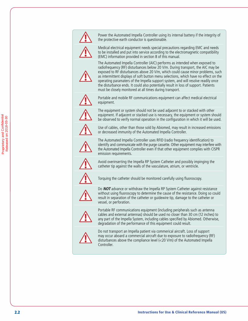
Power the Automated Impella Controller using its internal battery if the integrity of the protective earth conductor is questionable.
Medical electrical equipment needs special precautions regarding EMC and needs to be installed and put into service according to the electromagnetic compatibility (EMC) information provided in section 8 of this manual.
The Automated Impella Controller (AIC) performs as intended when exposed to radiofrequency (RF) disturbances below 20 V/m. During transport, the AIC may be exposed to RF disturbances above 20 V/m, which could cause minor problems, such as intermittent displays of soft button menu selections, which have no effect on the operating paramaters of the Impella support system, and will resolve readily once the disturbance ends. It could also potentially result in loss of support. Patients must be closely monitored at all times during transport.
Portable and mobile RF communications equipment can affect medical electrical equipment.
The equipment or system should not be used adjacent to or stacked with other equipment. If adjacent or stacked use is necessary, the equipment or system should be observed to verify normal operation in the configuration in which it will be used.
Use of cables, other than those sold by Abiomed, may result in increased emissions or decreased immunity of the Automated Impella Controller.
The Automated Impella Controller uses RFID (radio frequency identification) to identify and communicate with the purge cassette. Other equipment may interfere with the Automated Impella Controller even if that other equipment complies with CISPR emission requirements.
Avoid overinserting the Impella RP System Catheter and possibly impinging the catheter tip against the walls of the vasculature, atrium, or ventricle.
Torquing the catheter should be monitored carefully using fluoroscopy.
Do NOT advance or withdraw the Impella RP System Catheter against resistance without using fluoroscopy to determine the cause of the resistance. Doing so could result in separation of the catheter or guidewire tip, damage to the catheter or vessel, or perforation.
Portable RF communications equipment (including peripherals such as antenna cables and external antennas) should be used no closer than 30 cm (12 inches) to any part of the Impella System, including cables specified by Abiomed. Otherwise, degradation of the performance of this equipment could result.
Do not transport an Impella patient via commerical aircraft. Loss of support may occur aboard a commercial aircraft due to exposure to radiofrequency (RF) disturbances above the compliance level (<20 V/m) of the Automated Impella Controller.
Pro
prie
tary
and
Con
fiden
tial
R
elea
sed
on 2
018-
03-3
0

2.3Impella RP® System with the Automated Impella® Controller
CAUTIONS
Handle with care. The Impella RP System Catheter can be damaged during removal from packaging, preparation, insertion, and removal. Do NOT bend, pull, or place excess pressure on the catheter or mechanical components at any time.
Inspect the Impella RP System Set packaging while opening. In the event that any key components, including its end seal labels, are damaged excessively during shipment, the use of a back-up Impella RP System Set should be considered
Patients with tricuspid or pulmonary valve stenosis or insufficiency, and patients with prosthetic tricuspid or pulmonary valves, may be compromised by the use of the Impella RP System Catheter.
Use only original accessories and replacement parts supplied by Abiomed.
Do NOT use damaged or contaminated connector cables.
To prevent device failure, do NOT start the Impella RP System Catheter until the placement guidewire has been removed.
Do NOT remove the Impella RP System Catheter over the length of the placement guidewire.
When replacing the purge cassette, the replacement process must be completed within 90 seconds of disconnecting luer. The Impella RP System Catheter may be damaged if replacement takes longer than 90 seconds.
To prevent malfunction of the Automated Impella Controller, avoid long-term exposure to direct sunlight and excessive heat (40°C).
To prevent overheating and improper operation, do NOT block the cooling vents of the Automated Impella Controller while it is operating.
Do NOT kink or clamp any part of the Impella RP System Catheter.
Do NOT use the Impella RP System Catheter with a damaged or kinked introducer. Replace the introducer if a kink is observed.
The Li-Ion batteries must be charged for 5 hours prior to system operation in order to meet the runtime requirement of 1 hour. Failure to do so will yield a shorter runtime. After being unplugged, the Automated Impella Controller will operate for at least 60 minutes after the batteries have been fully charged.
Minimize exposure of Impella RP System components to sources of electromagnetic interference (EMI). Exposure to sources of EMI, such as cell phones and two-way radios, may cause operational interference. To clear interference, either increase the distance between system components and the EMI source or turn off the EMI source.
Operation of Impella RP System components may interfere with the operation of other devices. If interference occurs, increase the distance between the device and system components.
Cautions
Cautions indicate situations in which equipment may malfunction, be damaged, or cease to operate. The yellow symbol appears before caution messages.
2
WA
RN
ING
S A
ND
CA
UTIO
NS
Pro
prie
tary
and
Con
fiden
tial
R
elea
sed
on 2
018-
03-3
0
2.4 Instructions for Use & Clinical Reference Manual (US)
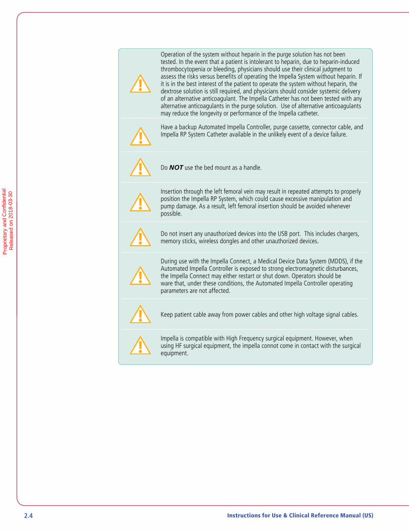
Operation of the system without heparin in the purge solution has not been tested. In the event that a patient is intolerant to heparin, due to heparin-induced thrombocytopenia or bleeding, physicians should use their clinical judgment to assess the risks versus benefits of operating the Impella System without heparin. If it is in the best interest of the patient to operate the system without heparin, the dextrose solution is still required, and physicians should consider systemic delivery of an alternative anticoagulant. The Impella Catheter has not been tested with any alternative anticoagulants in the purge solution. Use of alternative anticoagulants may reduce the longevity or performance of the Impella catheter.
Have a backup Automated Impella Controller, purge cassette, connector cable, and Impella RP System Catheter available in the unlikely event of a device failure.
Do NOT use the bed mount as a handle.
Insertion through the left femoral vein may result in repeated attempts to properly position the Impella RP System, which could cause excessive manipulation and pump damage. As a result, left femoral insertion should be avoided whenever possible.
Do not insert any unauthorized devices into the USB port. This includes chargers, memory sticks, wireless dongles and other unauthorized devices.
During use with the Impella Connect, a Medical Device Data System (MDDS), if the Automated Impella Controller is exposed to strong electromagnetic disturbances, the Impella Connect may either restart or shut down. Operators should be ware that, under these conditions, the Automated Impella Controller operating parameters are not affected.
Keep patient cable away from power cables and other high voltage signal cables.
Impella is compatible with High Frequency surgical equipment. However, when using HF surgical equipment, the impella connot come in contact with the surgical equipment.
Pro
prie
tary
and
Con
fiden
tial
R
elea
sed
on 2
018-
03-3
0

3 THE IMPELLA RP® SYSTEM CATHETER AND AUTOMATED IMPELLA CONTROLLER
OVERVIEW ....................................................................................................3.1
Reusable System Components .........................................................................3.2
Single-use System Components .......................................................................3.2
System Configuration.......................................................................................3.2
IMPELLA RP® SYSTEM CATHETER ............................................................... 3.3
Differential Pressure Sensor .............................................................................3.4
AUTOMATED IMPELLA® CONTROLLER .........................................................3.5
PURGE CASSETTE .........................................................................................3.6
ACCESSORIES ...............................................................................................3.8
Pro
prie
tary
and
Con
fiden
tial
R
elea
sed
on 2
018-
03-3
0

Pro
prie
tary
and
Con
fiden
tial
R
elea
sed
on 2
018-
03-3
0

3.1Impella RP® System with the Automated Impella® Controller
OVERVIEW
The Impella RP System Catheter is an intracardiac microaxial blood pump that supports a patient’s pulmonary circulation. The Impella RP System Catheter is inserted percutaneously through the femoral vein and into the pulmonary artery (see Figure 3.1).
Outlet area in PA
Inlet areain IVC
Femoral Vein Insertion
Figure 3.1 Impella RP® System Catheter in the Heart
When properly positioned, the Impella RP System Catheter delivers blood from the inlet area, which sits in the inferior vena cava, through the cannula, to the outlet opening in the pulmonary artery. Physicians and device operators monitor Impella RP System Catheter function on the display screen of the Automated Impella Controller.
The intent of the therapy with the Impella RP System is to provide a percutaneous circulatory support system to restore normal right heart hemodynamics, reduce right ventricular work, and allow the right heart time to potentially recover adequate contractile function or to be bridged to the next therapy.
This section describes the components of the Impella RP System Catheter and the Automated Impella Controller, as well as the accessory components.
3
THE IM
PE
LLA R
P® S
YSTE
M C
ATH
ETE
R A
ND
AU
TOM
ATE
D IM
PE
LLA® C
ON
TRO
LLER
Pro
prie
tary
and
Con
fiden
tial
R
elea
sed
on 2
018-
03-3
0
3.2 Instructions for Use & Clinical Reference Manual (US)
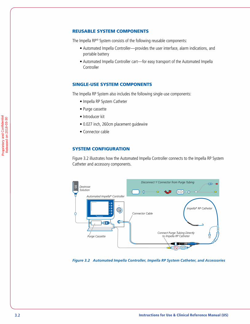
REUSABLE SYSTEM COMPONENTS
The Impella RP® System consists of the following reusable components:
• Automated Impella Controller—provides the user interface, alarm indications, and portable battery
• Automated Impella Controller cart—for easy transport of the Automated Impella Controller
SINGLE-USE SYSTEM COMPONENTS
The Impella RP System also includes the following single-use components:
• Impella RP System Catheter
• Purge cassette
• Introducer kit
• 0.027 inch, 260cm placement guidewire
• Connector cable
SYSTEM CONFIGURATION
Figure 3.2 illustrates how the Automated Impella Controller connects to the Impella RP System Catheter and accessory components.
DextroseSolution
Automated Impella® Controller
Purge Cassette
Impella® RP Catheter
D20
D5
Connector Cable
Connect Purge Tubing Directlyto Impella RP Catheter
Disconnect Y Connector from Purge Tubing
Figure 3.2 Automated Impella Controller, Impella RP System Catheter, and Accessories
Pro
prie
tary
and
Con
fiden
tial
R
elea
sed
on 2
018-
03-3
0

3.3Impella RP System with the Automated Impella Controller
IMPELLA RP® SYSTEM CATHETER
The Impella RP System Catheter is an intracardiac microaxial blood pump that delivers up to 4.0 liters of blood per minute from the inferior vena cava into the pulmonary artery. Figure 3.3 illustrates the Impella RP System Catheter. The Impella RP System Catheter has a specially designed three dimensional cannula that is sized to fit through the vessels and hearts of pediatric and adult patients with a Body Surface Area (BSA) equal to or greater than 1.5 m2. Table 3.1 describes each component from the pigtail at one end to the check valve on the other end.
ClearSidearm
CatheterShaft
InfusionFilter
Pressure Reservoir
Check Valve
Blue PumpPlug
Repositioning Unit
Pigtail
Outlet Area
Inlet Area
Pressure Sensor
Cannula
Motor Housing
Figure 3.3 Impella RP System Catheter
Table 3.1 Impella RP System Catheter Components
Component DescriptionPigtail The 6 Fr pigtail is attached to the cannula at the distal end of the
outlet area. It assists with stabilizing the catheter in the correct position in the pulmonary artery.
Outlet area The outlet area, located at the distal tip of the cannula, has 5 openings (windows) that allow blood to exit the cannula.
Cannula The 22 Fr cannula is designed for the anatomy of the right heart, to provide optimal and stable position during operation. The cannula is made of nitinol and covered in polyurethane with spiral shaped reinforcement integrated into the cannula.
Differential pressure sensor
A sensor that measures the pressure difference between the inside and outside of the cannula. The pressure value is used for monitoring flow during catheter operation.
3
THE IM
PE
LLA R
P S
YSTE
M C
ATH
ETE
R A
ND
AU
TOM
ATE
D IM
PE
LLA C
ON
TRO
LLER
Pro
prie
tary
and
Con
fiden
tial
R
elea
sed
on 2
018-
03-3
0

3.4 Instructions for Use & Clinical Reference Manual (US)
Table 3.1 Impella RP® System Catheter Components (continued)
Component DescriptionInlet area The proximal end of the cannula is attached to the inlet area where
blood enters the cannula.
Motor housing The 21 Fr motor housing consists of an encapsulated motor.
Catheter shaft An 11 Fr catheter shaft is located between the motor housing and the blue Impella plug. The lumen of the catheter shaft contains a purge lumen, an electrical cable, and a differential pressure measurement cable. The catheter shaft has transversal marks: • The transversal marks at 1 cm intervals aid in proper positioning.
Repositioning unit The repositioning unit consists of a sheath and an anticontamination sleeve with an anchoring ring.• The 11 Fr sheath (15 Fr outer diameter) with hemostatic valve
is located on the catheter shaft and allows repositioning of the catheter.
• The anchoring ring of the anticontamination sleeve secures the sheath to the catheter; turning in the counterclockwise direction enables movement of the catheter and turning in the clockwise direction disables movement.
Blue Impella plug The blue Impella plug has a clear sidearm and contains memory that retains operating parameters in case the patient needs to be transferred to another controller. The plug connects the Impella RP System Catheter to the Automated Impella Controller through a connector cable.
Clear sidearm The clear sidearm is attached to the purge cassette tubing. It leads to the infusion filter, the pressure reservoir, and the check valve.
Infusion filter The infusion filter prevents bacterial contamination and prevents air from entering the purge lumen.
Pressure reservoir The pressure reservoir includes a flexible rubber diaphragm that provides additional filling volume by means of an expansion chamber during purge solution change.
Check valve The yellow check valve ensures that purge fluid does not flow in the reverse direction when the purge solution is exchanged.
DIFFERENTIAL PRESSURE SENSOR
The Impella RP System Catheter has an electronic differential pressure sensor located at the proximal end of the cannula. The purpose of the pressure sensor is to generate the placement signal used to calculate the flow generated by the Impella RP System Catheter.
The pressure sensor is a flexible membrane integrated into the cannula. One side of the sensor is exposed to the blood pressure on the outside of the inlet area and the other side is exposed to the pressure of the blood inside of the cannula. The sensor generates an electrical signal proportional to the difference between the pressure outside the inlet area and the pressure inside the cannula. This signal is displayed on the Automated Impella Controller as the placement signal.
Pro
prie
tary
and
Con
fiden
tial
R
elea
sed
on 2
018-
03-3
0

3.5Impella RP System with the Automated Impella Controller
AUTOMATED IMPELLA® CONTROLLER
The Automated Impella Controller (see Figure 3.4) provides three vital functions to the operation of the Impella RP® System Catheter:
• The controller provides an interface for monitoring and controlling the function of the Impella RP System Catheter
• The controller provides a fluid purge to the Impella RP System Catheter
• The controller provides backup power when the Impella RP System is operated away from AC power
The controller weighs 26 lbs (11.8 kg) and can operate on its internal battery for at least 60 minutes when fully charged. Using the controller, the Impella RP System can be used by trained healthcare professionals in healthcare facilities and during medical transport (ie, ambulance, helicopter, or fixed-winged aircraft) environments.
Automated Impella Controller operation is described in detail in section 4 of this manual.
2016-07-22 10:09 AIC SN: IC4186 AIC V6.2
Figure 3.4 Automated Impella Controller – Front View
Automated Impella Controller Battery Power
The controller can operate on its internal lithium-ion (Li-Ion) battery for at least 60 minutes when fully charged.
3
THE IM
PE
LLA R
P S
YSTE
M C
ATH
ETE
R A
ND
AU
TOM
ATE
D IM
PE
LLA C
ON
TRO
LLER
Pro
prie
tary
and
Con
fiden
tial
R
elea
sed
on 2
018-
03-3
0

3.6 Instructions for Use & Clinical Reference Manual (US)
PURGE CASSETTE
Do NOT use saline in the purge system.
The purge cassette delivers rinsing fluid to the Impella RP® System Catheter. The purge fluid (typically 5% dextrose solution in water) flows from the purge cassette through the catheter to the microaxial blood pump to prevent blood from entering the motor. When the purge cassette is properly installed in the Automated Impella Controller, the Abiomed logo is upright and facing you. Figure 3.5 illustrates the purge cassette and related components. Table 3.2 describes each component.
Figure 3.5 Purge Cassette
Discard the Y Connector
Disconnect and discard the Y connector from the purge cassette tubing. For the Impella RP System, the yellow luer on the end of the purge tubing connects directly to the yellow luer on the Impella RP Catheter.
Pro
prie
tary
and
Con
fiden
tial
R
elea
sed
on 2
018-
03-3
0

3.7Impella RP® System with the Automated Impella® Controller
Table 3.2 Purge Cassette Components
Component DescriptionPurge fluid spike One end spikes the purge fluid bag and the other end connects the
bag to the purge cassette supply line
Supply line Carries fluid from the purge fluid bag to the purge cassette
Purge cassette Contains the components for delivering the purge fluid; maintains the pressure barrier between the blood and the motor to prevent blood from entering the motor
Purge disc Transmits pressure to the controller based on the purge pressure in the purge tubing; a sensor in the controller measures the pressure so that it can be displayed on the screen and used by the purge pressure algorithm to maintain the purge pressure
Purge tubing Carries purge fluid from the purge cassette to the Impella RP® System Catheter
Yellow luer connector Connects the purge tubing to the check valve (yellow luer lock) on the Impella RP System Catheter
Y connector Adapter that connects the purge cassette tubing to the Impella Catheter; used with the Impella 2.5® Catheter but removed when you are using the Impella RP System Catheter
3
THE IM
PE
LLA R
P® S
YSTE
M C
ATH
ETE
R A
ND
AU
TOM
ATE
D IM
PE
LLA® C
ON
TRO
LLER
Pro
prie
tary
and
Con
fiden
tial
R
elea
sed
on 2
018-
03-3
0

3.8 Instructions for Use & Clinical Reference Manual (US)
ACCESSORIES
Table 3.3 illustrates and describes the accessories used with the Impella RP® System Catheter and Automated Impella® Controller.
Table 3.3 Impella RP System Catheter and Automated Impella Controller Accessories
Component Description
Figure 3.6 White Connector Cable
The white connector cable connects the Impella RP System Catheter to the Automated Impella Controller. Clips on the cable are used to secure the purge tubing to the cable.• The socket at the black end of the cable
connects to the blue Impella plug.• The white plug at the opposite end of the cable
is inserted into the blue catheter plug on the front of the Automated Impella Controller.
Figure 3.7 Introducer kit
The introducer kit is used to place the Impella RP System Catheter. It contains:• 23 Fr peel-away introducer with dilator• 8 Fr, 12 Fr, 16 Fr, and 20 Fr supplemental dilators• 0.035 inch x 150 cm guidewire
Figure 3.8 Placement Guidewire
The 0.027 inch, 260 cm placement guidewire is available for the placement of the Impella RP System Catheter.
Pro
prie
tary
and
Con
fiden
tial
R
elea
sed
on 2
018-
03-3
0
3.9Impella RP® System with the Automated Impella® Controller 3.9
Table 3.3 Impella RP® System Catheter and Automated Impella® Controller Accessories (continued)
Component Description
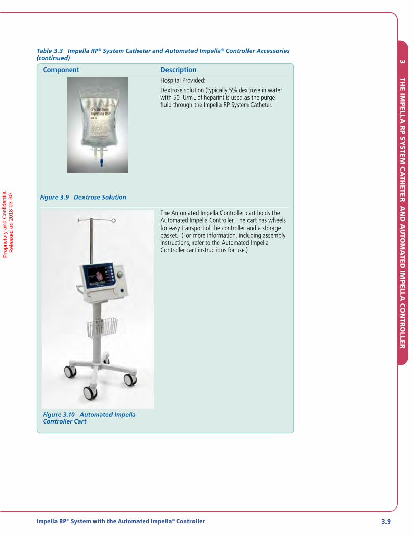
Figure 3.9 Dextrose Solution
Hospital Provided:Dextrose solution (typically 5% dextrose in water with 50 IU/mL of heparin) is used as the purge fluid through the Impella RP System Catheter.
Figure 3.10 Automated Impella Controller Cart
The Automated Impella Controller cart holds the Automated Impella Controller. The cart has wheels for easy transport of the controller and a storage basket. (For more information, including assembly instructions, refer to the Automated Impella Controller cart instructions for use.)
3
THE IM
PE
LLA R
P® S
YSTE
M C
ATH
ETE
R A
ND
AU
TOM
ATE
D IM
PE
LLA® C
ON
TRO
LLER
3
THE IM
PE
LLA R
P S
YSTE
M C
ATH
ETE
R A
ND
AU
TOM
ATE
D IM
PE
LLA C
ON
TRO
LLER
Pro
prie
tary
and
Con
fiden
tial
R
elea
sed
on 2
018-
03-3
0

Pro
prie
tary
and
Con
fiden
tial
R
elea
sed
on 2
018-
03-3
0
4 USING THE AUTOMATED IMPELLA® CONTROLLER
OVERVIEW ....................................................................................................4.1
AUTOMATED IMPELLA® CONTROLLER FEATURES ........................................4.1
AUTOMATED IMPELLA® CONTROLLER DISPLAY ......................................... 4.5
PLACEMENT SCREEN ................................................................................... 4.8
Placement Signal Waveform.............................................................................4.8
Motor Current Waveform .................................................................................4.9
PURGE SCREEN .............................................................................................4.9
Purge Flow .................................................................................................... 4.10
Purge Pressure ............................................................................................... 4.10
INFUSION HISTORY ....................................................................................4.10
MOBILE OPERATION ................................................................................... 4.11
Pro
prie
tary
and
Con
fiden
tial
R
elea
sed
on 2
018-
03-3
0

Pro
prie
tary
and
Con
fiden
tial
R
elea
sed
on 2
018-
03-3
0
4.1Impella RP® System with the Automated Impella® Controller
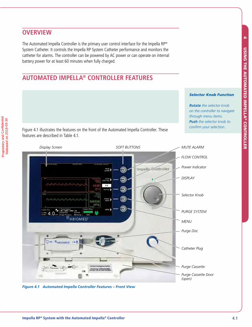
OVERVIEW
The Automated Impella Controller is the primary user control interface for the Impella RP® System Catheter. It controls the Impella RP System Catheter performance and monitors the catheter for alarms. The controller can be powered by AC power or can operate on internal battery power for at least 60 minutes when fully charged.
AUTOMATED IMPELLA® CONTROLLER FEATURES
IMPORTANT NOTE: The underside of the Automated Impella Controller has a battery switch to turn on the batteries. This switch is turned off for shipping purposes. Before operating the Automated Impella Controller for the first time, make sure you turn this switch on. If the battery switch is not turned on, the Automated Impella Controller will not be able to operate on battery power.
Figure 4.1 illustrates the features on the front of the Automated Impella Controller. These features are described in Table 4.1.
Purge Cassette Door (open)
Purge Cassette
SOFT BUTTONSDisplay Screen
Catheter Plug
Purge Disc
MUTE ALARM
FLOW CONTROL
DISPLAY
Selector Knob
Power Indicator
PURGE SYSTEM
MENU
Figure 4.1 Automated Impella Controller Features – Front View
Selector Knob Function
Rotate the selector knob on the controller to navigate through menu items. Push the selector knob to confirm your selection.
4
US
ING
THE A
UTO
MA
TED
IMP
ELLA
® CO
NTR
OLLE
RP
ropr
ieta
ry a
nd C
onfid
entia
l
Rel
ease
d on
201
8-03
-30
4.2 Instructions for Use & Clinical Reference Manual (US)
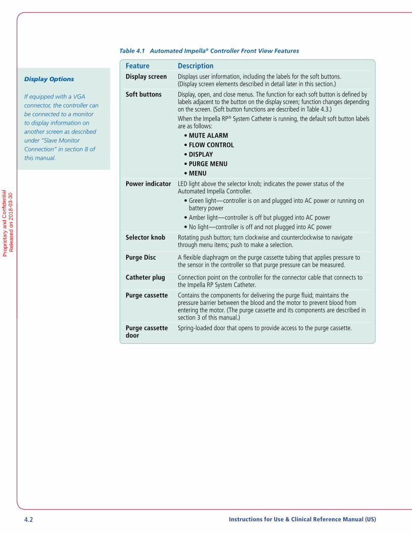
Table 4.1 Automated Impella® Controller Front View Features
Feature DescriptionDisplay screen Displays user information, including the labels for the soft buttons.
(Display screen elements described in detail later in this section.)
Soft buttons Display, open, and close menus. The function for each soft button is defined by labels adjacent to the button on the display screen; function changes depending on the screen. (Soft button functions are described in Table 4.3.)When the Impella RP® System Catheter is running, the default soft button labels are as follows:
• MUTE ALARM• FLOW CONTROL• DISPLAY• PURGE MENU• MENU
Power indicator LED light above the selector knob; indicates the power status of the Automated Impella Controller.
• Green light—controller is on and plugged into AC power or running on battery power
• Amber light—controller is off but plugged into AC power • No light—controller is off and not plugged into AC power
Selector knob Rotating push button; turn clockwise and counterclockwise to navigate through menu items; push to make a selection.
Purge Disc A flexible diaphragm on the purge cassette tubing that applies pressure to the sensor in the controller so that purge pressure can be measured.
Catheter plug Connection point on the controller for the connector cable that connects to the Impella RP System Catheter.
Purge cassette Contains the components for delivering the purge fluid; maintains the pressure barrier between the blood and the motor to prevent blood from entering the motor. (The purge cassette and its components are described in section 3 of this manual.)
Purge cassette door
Spring-loaded door that opens to provide access to the purge cassette.
Display Options
If equipped with a VGA connector, the controller can be connected to a monitor to display information on another screen as described under “Slave Monitor Connection” in section 8 of this manual.
Pro
prie
tary
and
Con
fiden
tial
R
elea
sed
on 2
018-
03-3
0

4.3Impella RP® System with the Automated Impella® Controller
Figure 4.2 illustrates the features on the left and right sides of the Automated Impella® Controller. These features are described in Table 4.2.
Purge Cassette Door Release
Bed Mount
Power Switch
AC Fuses
AC Plug
EquipotentialGround Stud
VGA OUT
Ethernet Jack
USB Connector Service
Figure 4.2 Automated Impella Controller Features – Side Views
4
US
ING
THE A
UTO
MA
TED
IMP
ELLA
® CO
NTR
OLLE
RP
ropr
ieta
ry a
nd C
onfid
entia
l
Rel
ease
d on
201
8-03
-30
4.4 Instructions for Use & Clinical Reference Manual (US)
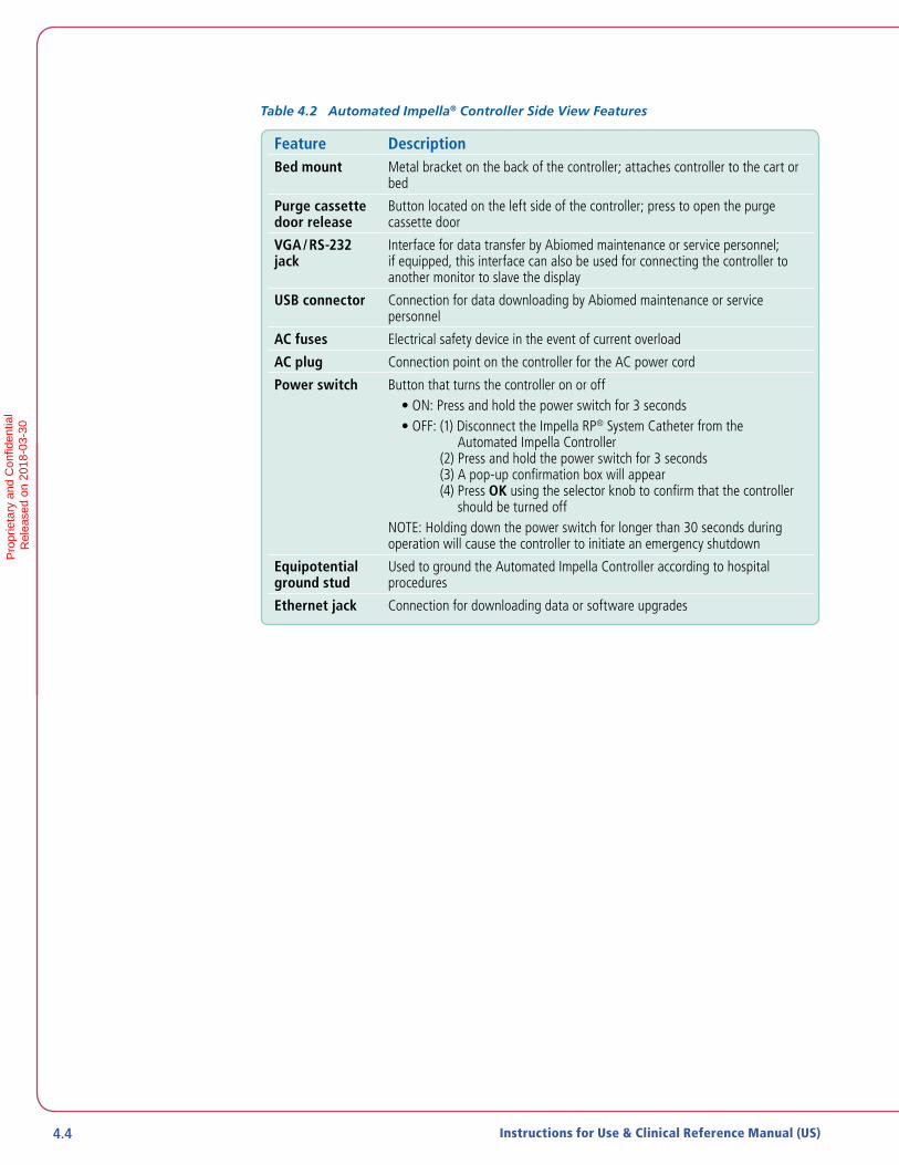
Table 4.2 Automated Impella® Controller Side View Features
Feature DescriptionBed mount Metal bracket on the back of the controller; attaches controller to the cart or
bed
Purge cassette door release
Button located on the left side of the controller; press to open the purge cassette door
VGA / RS-232 jack
Interface for data transfer by Abiomed maintenance or service personnel; if equipped, this interface can also be used for connecting the controller to another monitor to slave the display
USB connector Connection for data downloading by Abiomed maintenance or service personnel
AC fuses Electrical safety device in the event of current overload
AC plug Connection point on the controller for the AC power cord
Power switch Button that turns the controller on or off• ON: Press and hold the power switch for 3 seconds• OFF: (1) Disconnect the Impella RP® System Catheter from the
Automated Impella Controller (2) Press and hold the power switch for 3 seconds (3) A pop-up confirmation box will appear (4) Press OK using the selector knob to confirm that the controller
should be turned off NOTE: Holding down the power switch for longer than 30 seconds during operation will cause the controller to initiate an emergency shutdown
Equipotential ground stud
Used to ground the Automated Impella Controller according to hospital procedures
Ethernet jack Connection for downloading data or software upgrades
Pro
prie
tary
and
Con
fiden
tial
R
elea
sed
on 2
018-
03-3
0

4.5Impella RP® System with the Automated Impella® Controller
AUTOMATED IMPELLA® CONTROLLER DISPLAYThe Automated Impella Controller screens have several common display elements. Each element is shown in Figure 4.3 and described in Table 4.3.
100%L/min5.2 Max________________________
4.8 Min
v6.2
System Dateand Time
AlarmWindow
CatheterSerial Number
Soft ButtonLabels
CentralDisplay
Area
Purge System AreaFlow Area System Power Area
AIC SerialNumber
Table 4.3 Automated Impella Controller Display Elements
Display Element DescriptionAlarm window The alarm window displays up to 3 alarms simultaneously, in order of
priority from top to bottom. For each alarm, the alarm window displays:
• Alarm header – displayed in the left column; window is color-coded red for critical alarms, yellow for serious alarms, white for advisory notifications, gray for resolved alarms
• Alarm subhead (if applicable) – further describes the alarm condition• Detailed text – up to 3 lines of instructions for resolving the alarm
condition are displayed in the right column of the alarm window next to the alarm header and subhead information
(See section 7 of this manual for further discussion of alarms.)
Catheter serial number Displayed in the upper left of the display screen if a catheter is connected to the controller.
System date and time The current date (YYYY-MM-DD) and time (24-hour format; HH:MM) are displayed in the upper center of the screen display. (In this example it is March 17, 2017 at 10:09am.)
Automated Impella Controller Serial Number and SW version
The AIC serial number and the current SW version are shown in the upper right of the display screen
4
US
ING
THE A
UTO
MA
TED
IMP
ELLA
® CO
NTR
OLLE
RP
ropr
ieta
ry a
nd C
onfid
entia
l
Rel
ease
d on
201
8-03
-30

4.6 Instructions for Use & Clinical Reference Manual (US)
Table 4.3 Automated Impella® Controller Display Elements (continued)
Display Element DescriptionMute alarm indicator Displayed in place of the words “MUTE ALARM” when an alarm is
silenced. (See section 7 of this manual for more information about the mute alarm function; Figure 6.1 illustrates the mute alarm indicator.)
• Yellow bell with red X displayed when an alarm is muted• Not displayed when an alarm is active (but not muted) or when there
are no active alarms
Soft button labels The soft buttons on the Automated Impella Controller have corresponding labels adjacent to them on the display screen. These labels change depending on the type of screen displayed. (Refer to Appendix A in this manual for more details about the menu structure.)MUTE ALARM - Mutes (silences) active alarmsFLOW CONTROL - Allows you to control the flow of the Impella CatheterDISPLAY - Brings up the Display menu for viewing waveforms and navigating to other screen displaysPURGE MENU - Brings up the Purge Menu for changing the purge fluid, purge cassette and fluid or de-airing the purge system.MENU - Brings up a menu of options related to controller settings, alarm history and starting a case.
Additional soft button functions may appear during specific controller procedures.START - Starts the specified procedure.NEXT - Advances to the next screenCANCEL - Exits out of the current menu.BACK - Returns to the previous screenEXIT - Exits the current procedure.DONE- Done completes the current step or procedure.
System power area System power information is displayed to the right of the purge system information on the bottom of the display screen.
Battery status – Bar within battery symbol indicates the overall remaining capacity of the batteries• Full green bar for fully charged battery• Partial green bar for battery that is at least 50% charged• Partial yellow bar for battery that is between 16% and 50% charged• Partial red bar for battery that is less than or equal to 15% charged• Moving gray bar for battery that is in charging mode• Numeric percentage of battery power remaining displayed below the
battery icon
AC plug indicator• Green plug indicates that the controller is running on AC power• Gray plug with a red X indicates no AC power detected and the
controller is running on battery power
Purge System Stabilization
The purge system must stabilize after case start, a purge procedure, or resolution of a purge alarm. During this time, it may take up to 3 minutes for purge system information to display on the screen.
Pro
prie
tary
and
Con
fiden
tial
R
elea
sed
on 2
018-
03-3
0

4.7Impella RP® System with the Automated Impella® Controller
Table 4.3 Automated Impella® Controller Display Elements (continued)
Display Element DescriptionPurge system area Information about the purge system is displayed to the right of the flow
area at the bottom of the display screen.
Purge system marquee—scrolls from left to right when purge system is operating• Slow scrolling represents normal purge flow rate• Fast scrolling represents bolus flow rate
Purge flow• Current purge flow displayed in mL/hr below the purge system marquee
if the purge flow is known• Not displayed when the purge system is stabilizing, when there is no
purge cassette, or when the procedure has not yet started• Current purge pressure (pressure of the purge fluid delivered through
the catheter to the motor) displayed in mmHg below the purge flow
Flow area Information about Impella RP® System Catheter flow is displayed in the lower left corner of the display screen.
Max/Min• Max/Min displays the range for the flow rate
Current flow rate• Mean catheter flow displayed in liters per minute (L/min)• If the system is unable to calculate flow, a yellow triangular caution icon
is displayed with the message “Flow Calculation Disabled”
Catheter operation icon• The circular catheter operation icon rotates when the Impella RP System
Catheter is running
Central display area On the placement screen, the central display area displays two waveform signals, described in the “Placement Screen” discussion below.
4
US
ING
THE A
UTO
MA
TED
IMP
ELLA
® CO
NTR
OLLE
RP
ropr
ieta
ry a
nd C
onfid
entia
l
Rel
ease
d on
201
8-03
-30

4.8 Instructions for Use & Clinical Reference Manual (US)
PLACEMENT SCREEN
The placement screen (see Figure 4.4) displays real-time operating data for the system. The screen displays the placement signal and motor current waveforms as well as the maximum/minimum and average values for each waveform in the central display area of the screen.
Use the DISPLAY soft button to navigate to the placement screen.
Figure 4.4 Placement Screen
Figure 4.4 shows two time-based waveform signals from different sources.
• Placement signal waveform
• Motor current waveform
PLACEMENT SIGNAL WAVEFORM
The placement signal waveform displays a pressure measurement from the differential pressure sensor. The scale for the placement signal waveform is displayed to the left of the waveform. The scale can be adjusted in increments of 10 mm Hg.
To the right of the waveform is a display that labels the waveform, provides the units of measurement, and shows the maximum and minimum values and the average value from the samples received. At the bottom of that window is the time scale, which you can set by pressing the DISPLAY soft button.
Pro
prie
tary
and
Con
fiden
tial
R
elea
sed
on 2
018-
03-3
0

4.9Impella RP® System with the Automated Impella® Controller
MOTOR CURRENT WAVEFORM
Motor current is a measure of the energy intake of the Impella RP® System Catheter motor. The energy intake varies with motor speed and the pressure difference between the inlet and outlet areas of the cannula.
The scale for the motor current waveform is displayed to the left of the waveform. The default scaling is 0–1000 mA. It is adjustable in 100 mA increments for the Impella RP System Catheter, with a minimum difference between upper and lower limits of 200 mA and a maximum difference of 1000 mA.
To the right of the waveform is a display that labels the waveform, provides the units of measurement, and shows the maximum and minimum values and the average value from the samples received. You can set the time scale at the bottom of that window by pressing the DISPLAY soft button.
PURGE SCREEN
The purge screen (see Figure 4.5) displays purge system data. In the central display area of the screen, the purge flow rate and purge pressure are plotted as a function of time. To the right of the plots, the current purge flow rate and purge pressure are displayed.
Use the DISPLAY soft button to navigate to the purge screen.
Impella Flow
4.0Purge System
Purge Flow: 20.0 ml/hr
System Power
MUTE ALARM
0.0
DISPLAY
0.0
MENU
PURGESYSTEM
Impella RP S/N: 123456 2016-07-22 10:09
100%
P-LEVEL
P-8
L/min4.2 Max________________________
3.8 Min
AIC SN: IC4186 V6.2
30
0
1500
0
Purge Pressure
600(mmHg)
1 hr.
Purge Flow(ml / hr)
7
1 hr.
Figure 4.5 Purge Screen
4
US
ING
THE A
UTO
MA
TED
IMP
ELLA
® CO
NTR
OLLE
RP
ropr
ieta
ry a
nd C
onfid
entia
l
Rel
ease
d on
201
8-03
-30

4.10 Instructions for Use & Clinical Reference Manual (US)
PURGE FLOW
The purge flow rate delivered by the purge cassette is displayed in mL/hr. The standard scale for the purge flow (0–30 mL/hr) is displayed to the left of the purge flow plot. The maximum value on this scale can be adjusted from 20 mL/hr to 200 mL/hr in increments of 10 mL/hr.
To the right of the plot is a display that labels the plot and shows the most recent value update. You can set the time scale at the bottom of the window by pressing the DISPLAY soft button.
An Advisory Alarm can also be turned on via the SETTINGS menu.
PURGE PRESSURE
The purge pressure generated by the purge cassette is displayed in mmHg. The standard scale for the purge pressure (0–1500 mmHg) is displayed to the left of the purge pressure plot. The maximum value on this scale can be adjusted from 100 mmHg to 2000 mmHg in increments of 100 mmHg.
To the right of the plot is a display that labels the plot and shows the most recent value update. You can set the time scale at the bottom of the window by pressing the DISPLAY soft button.
INFUSION HISTORY
The infusion history screen displays the infusion volume as well as the amount of heparin and dextrose infused each hour. The current time period is displayed at the top of the list. The calculations begin when the case start procedure is completed and Impella RP® System Catheter flow rate is greater than 0 L/min. The infusion history screen updates after each milliliter of purge fluid is delivered and after each unit of heparin and dextrose is delivered.
Use the DISPLAY soft button to navigate to the infusion history screen.
Figure 4.6 shows a sample infusion history screen.
Pro
prie
tary
and
Con
fiden
tial
R
elea
sed
on 2
018-
03-3
0

4.11Impella RP® System with the Automated Impella® Controller
Figure 4.6 Infusion History Screen
MOBILE OPERATION
The Li-Ion batteries must be charged for 5 hours prior to system operation in order to meet the runtime requirement of 1 hour. Failure to do so will yield a shorter runtime. After being unplugged, the Automated Impella Controller will operate for at least 60 minutes after the batteries have been fully charged.
The Automated Impella Controller can be operated on internal battery power when it is not connected to AC power.
Disconnect the Automated Impella Controller from AC power.
The Automated Impella Controller beeps once every 5 minutes to alert you that it is running on battery power and a white advisory notification appears in the alarm area on the screen. The AC power icon turns gray with an X through it.
When the Automated Impella Controller is connected back to AC power, the white advisory notification turns gray and the AC power icon turns green.
4
US
ING
THE A
UTO
MA
TED
IMP
ELLA
® CO
NTR
OLLE
RP
ropr
ieta
ry a
nd C
onfid
entia
l
Rel
ease
d on
201
8-03
-30

Pro
prie
tary
and
Con
fiden
tial
R
elea
sed
on 2
018-
03-3
0

13
5 USING THE AUTOMATED IMPELLA CONTROLLER WITH THE IMPELLA RP® SYSTEM CATHETER
STARTUP .......................................................................................................5.1
Supplies Needed .............................................................................................. 5.1
Turning on the Automated Impella Controller ...................................................5.2
The Startup Screen ..........................................................................................5.3
CASE START ..................................................................................................5.4
Case Start........................................................................................................5.4
Insert Purge Cassette.......................................................................................5.5
Connect the Connector Cable ..........................................................................5.6
Secure the Purge Tubing ..................................................................................5.9
Impella RP System Configuration ................................................................... 5.10
INSERTING THE IMPELLA RP® SYSTEM CATHETER ....................................5.10
POSITIONING AND STARTING THE IMPELLA RP® SYSTEM CATHETER ...... 5.12
USE OF THE REPOSITIONING SHEATH AND THE 23 FR PEEL- AWAY INTRODUCER ...................................................................................5.13
P-LEVELS ....................................................................................................5.14
SUCTION .....................................................................................................5.14
PURGE CASSETTE PROCEDURES ................................................................5.15
Change Cassette and Bag .............................................................................. 5.15
Change Purge Fluid Bag ................................................................................ 5.16
De-Air Purge System ...................................................................................... 5.16
Air Detected Alert.......................................................................................... 5.17
TROUBLESHOOTING THE PURGE SYSTEM .................................................. 5.17
Purge Pressure Low ....................................................................................... 5.17
Purge System Open ....................................................................................... 5.18
Purge Pressure High and Purge System Blocked ............................................. 5.18
PATIENT WEANING .....................................................................................5.19
REMOVING THE IMPELLA RP® SYSTEM CATHETER ....................................5.19
Pro
prie
tary
and
Con
fiden
tial
R
elea
sed
on 2
018-
03-3
0

Pro
prie
tary
and
Con
fiden
tial
R
elea
sed
on 2
018-
03-3
0

5.1Impella RP® System with the Automated Impella® Controller
STARTUP
Do NOT use an Impella RP® System if any part of the system is damaged.
The sterile components of the Impella RP System can be used only if the sterilization indicators show that the contents have been sterilized, the packaging is not damaged, and the expiration date has not elapsed.
Do NOT resterilize or reuse the Impella RP System Catheter. It is a disposable device and is intended for single use only. Reuse, reprocessing, or resterilization may compromise the structural integrity of the catheter and/or lead to catheter failure which, in turn, may result in patient injury, illness, or death.
To prevent malfunction of the Automated Impella Controller, avoid long-term exposure to direct sunlight and excessive heat (40°C).
To prevent overheating and improper operation, do NOT block the cooling vents of the Automated Impella Controller while it is operating.
The Li-Ion batteries must be charged for 5 hours prior to system operation in order to meet the runtime requirement of 1 hour. Failure to do so will yield a shorter runtime. After being unplugged, the Automated Impella Controller will operate for at least 60 minutes after the batteries have been fully charged.
Have a backup Automated Impella Controller, purge cassette, connector cable, and Impella RP System Catheter available in the unlikely event of a device failure.
SUPPLIES NEEDED
• Automated Impella Controller
• Impella RP System Catheter and accessories
• Femoral length, balloon-tipped flow-directed catheter
• 500 cc bag of dextrose solution for purge solution in water (5% recommended; 5% to 40% acceptable) with 50 IU heparin/mL
5
USIN
G TH
E AU
TOM
ATE
D IM
PE
LLA® C
ON
TRO
LLER
WITH
THE IM
PE
LLA R
P® SY
STEM
CA
THETE
RP
ropr
ieta
ry a
nd C
onfid
entia
l
Rel
ease
d on
201
8-03
-30

5.2 Instructions for Use & Clinical Reference Manual (US)
TURNING ON THE AUTOMATED IMPELLA CONTROLLER
To turn the controller on:
1. Press and hold the power switch on the right side of the Automated Impella Controller for 3 seconds (see Figure 5.1).
Power Switchon Right Side of
Impella® Controller
Figure 5.1 Automated Impella Controller Power Switch
The Automated Impella Controller automatically performs a system test when turned on.
A display bar shows the progress of the system test. If the system test passes, the system displays the startup screen (see Figure 5.2).
If the system test fails, the controller displays a system self check failure message: SYSTEM SELF CHECK FAILED.
CHANGE CONSOLE IMMEDIATELY.
The controller displays the reason for the system test failure at the bottom of the screen.
Battery Switch
Before operating the Automated Impella Controller for the first time, turn on the switch on the underside of the controller to turn on the batteries.
Pro
prie
tary
and
Con
fiden
tial
R
elea
sed
on 2
018-
03-3
0

5.3Impella RP® System with the Automated Impella® Controller
THE STARTUP SCREEN
The startup screen (see Figure 5.2) appears when you successfully turn on the Automated Impella Controller.
Figure 5.2 Automated Impella Controller Startup Screen
The startup screen displays the current version of the software that the Automated Impella Controller is running:
The startup screen also displays system power information along the bottom of the screen and three active soft buttons—MUTE ALARM, START NEW CASE, and MENU —along the right side of the screen.
Check Date and Time
The current date and time appear at the top of the startup screen. Confirm that these are correct.
5
USIN
G TH
E AU
TOM
ATE
D IM
PE
LLA® C
ON
TRO
LLER
WITH
THE IM
PE
LLA R
P® SY
STEM
CA
THETE
RP
ropr
ieta
ry a
nd C
onfid
entia
l
Rel
ease
d on
201
8-03
-30

5.4 Instructions for Use & Clinical Reference Manual (US)
CASE START
Fluoroscopy is required to guide placement of the Impella RP® System Catheter. The small placement guidewire must be reliably observed at all times.
The sterile components of the Impella RP System can be used only if the sterilization indicators show that the contents have been sterilized, the packaging is not damaged, and the expiration date has not elapsed.
Avoid manual compression of the inlet, outlet, or sensor areas of the cannula assembly.
Do NOT remove the Impella RP System Catheter over the length of the placement guidewire.
Handle with care. The Impella RP System Catheter can be damaged during removal from packaging, preparation, insertion, and removal. Do NOT bend, pull, or place excess pressure on the catheter or mechanical components at any time.
Do NOT kink or clamp any part of the Impella RP System Catheter.
CASE START
1. Press the START NEW CASE soft button from the startup screen or plug in a new Impella Catheter. “Case Start” can also be selected by pressing the MENU soft key.
2. The controller displays the screen shown in Figure 5.3.
Figure 5.3 Initial Case Start Screen
Sensitive Medical Device
The Impella RP System Catheter is a sensitive medical device with extremely fine tolerances. In particular, the inlet and outlet areas of the catheter assembly may be damaged if subjected to strong external forces.
Pro
prie
tary
and
Con
fiden
tial
R
elea
sed
on 2
018-
03-3
0
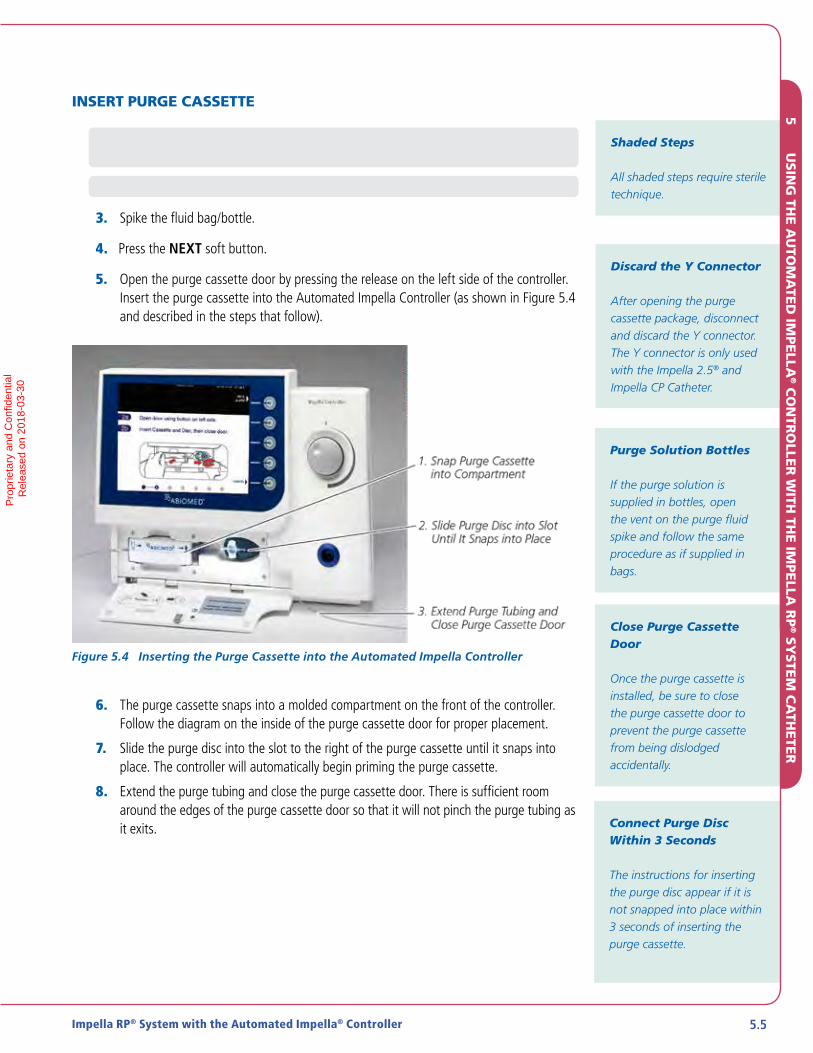
5.5Impella RP® System with the Automated Impella® Controller
INSERT PURGE CASSETTE
1. Open the purge cassette package. Disconnect and discard the Y connector. Secure the YELLOW luer to the sterile field
2. Pass the purge cassette and spike off the sterile field.
3. Spike the fluid bag/bottle.
4. Press the NEXT soft button.
5. Open the purge cassette door by pressing the release on the left side of the controller. Insert the purge cassette into the Automated Impella Controller (as shown in Figure 5.4 and described in the steps that follow).
Figure 5.4 Inserting the Purge Cassette into the Automated Impella Controller
6. The purge cassette snaps into a molded compartment on the front of the controller. Follow the diagram on the inside of the purge cassette door for proper placement.
7. Slide the purge disc into the slot to the right of the purge cassette until it snaps into place. The controller will automatically begin priming the purge cassette.
8. Extend the purge tubing and close the purge cassette door. There is sufficient room around the edges of the purge cassette door so that it will not pinch the purge tubing as it exits.
Shaded Steps
All shaded steps require sterile technique.
Discard the Y Connector
After opening the purge cassette package, disconnect and discard the Y connector. The Y connector is only used with the Impella 2.5® and Impella CP Catheter.
Purge Solution Bottles
If the purge solution is supplied in bottles, open the vent on the purge fluid spike and follow the same procedure as if supplied in bags.
Close Purge Cassette Door
Once the purge cassette is installed, be sure to close the purge cassette door to prevent the purge cassette from being dislodged accidentally.
Connect Purge Disc Within 3 Seconds
The instructions for inserting the purge disc appear if it is not snapped into place within 3 seconds of inserting the purge cassette.
5
USIN
G TH
E AU
TOM
ATE
D IM
PE
LLA® C
ON
TRO
LLER
WITH
THE IM
PE
LLA R
P® SY
STEM
CA
THETE
RP
ropr
ieta
ry a
nd C
onfid
entia
l
Rel
ease
d on
201
8-03
-30

5.6 Instructions for Use & Clinical Reference Manual (US)
CONNECT THE CONNECTOR CABLE
1. Remove the Impella RP® System Catheter from its package using sterile technique and inspect the catheter, including its connector, for damage.
2. Remove the white connector cable from its package using sterile technique.
3. Inspect the cable for damage, including damage to the connector pins at the controller end.
4. Secure the grey end of the cable to the sterile field.
5. Insert the catheter plug into the connector cable socket (grey end). The tab and the slot must be aligned during connection (see Figure 5.5).
Connector Cable Socket (Black end)
Catheter Plug
Figure 5.5 Inserting the Catheter Plug into the Connector Cable
6. Pull back on the connection to make sure that the plug has snapped into place.
7. Snap the plastic clip (located on the pressure reservoir of the clear sidearm) to the connector cable as shown in Figure 5.6.
Figure 5.6 Snapping Purge Clip to Connector Cable
8. Pass the sterile connector cable from the Impella RP System Catheter off the sterile field.
9. Line up the notch on the connector cable with the notch in the blue catheter plug on the front of the Automated Impella Controller and plug the cable into the controller.
Important Step
Snapping the purge clip on the pressure reservoir to the connector cable is important to prevent the tube from kinking.
Pro
prie
tary
and
Con
fiden
tial
R
elea
sed
on 2
018-
03-3
0

5.7Impella RP® System with the Automated Impella® Controller
10. If you have not already done so, disconnect and discard the Y connector with the red and yellow luers from the purge tubing.
11. Connect the yellow luer on the end of the purge tubing to the yellow luer on the clear sidearm of the Impella RP® System Catheter as shown in Figure 5.7.
Figure 5.7 Connecting the Luer to the Impella RP System Catheter
12. When the controller detects that the luer is connected, it automatically begins priming the purge lumen.
Figure 5.8 Priming the Purge
5
USIN
G TH
E AU
TOM
ATE
D IM
PE
LLA® C
ON
TRO
LLER
WITH
THE IM
PE
LLA R
P® SY
STEM
CA
THETE
RP
ropr
ieta
ry a
nd C
onfid
entia
l
Rel
ease
d on
201
8-03
-30
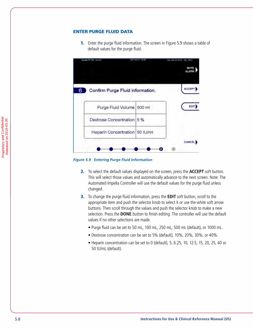
5.8 Instructions for Use & Clinical Reference Manual (US)
ENTER PURGE FLUID DATA
1. Enter the purge fluid information. The screen in Figure 5.9 shows a table of default values for the purge fluid.
Figure 5.9 Entering Purge Fluid Information
2. To select the default values displayed on the screen, press the ACCEPT soft button. This will select those values and automatically advance to the next screen. Note: The Automated Impella Controller will use the default values for the purge fluid unless changed.
3. To change the purge fluid information, press the EDIT soft button, scroll to the appropriate item and push the selector knob to select it or use the white soft arrow buttons. Then scroll through the values and push the selector knob to make a new selection. Press the DONE button to finish editing. The controller will use the default values if no other selections are made.
• Purge fluid can be set to 50 mL, 100 mL, 250 mL, 500 mL (default), or 1000 mL.
• Dextrose concentration can be set to 5% (default), 10%, 20%, 30%, or 40%.
• Heparin concentration can be set to 0 (default), 5, 6.25, 10, 12.5, 15, 20, 25, 40 or 50 IU/mL (default).
Pro
prie
tary
and
Con
fiden
tial
R
elea
sed
on 2
018-
03-3
0
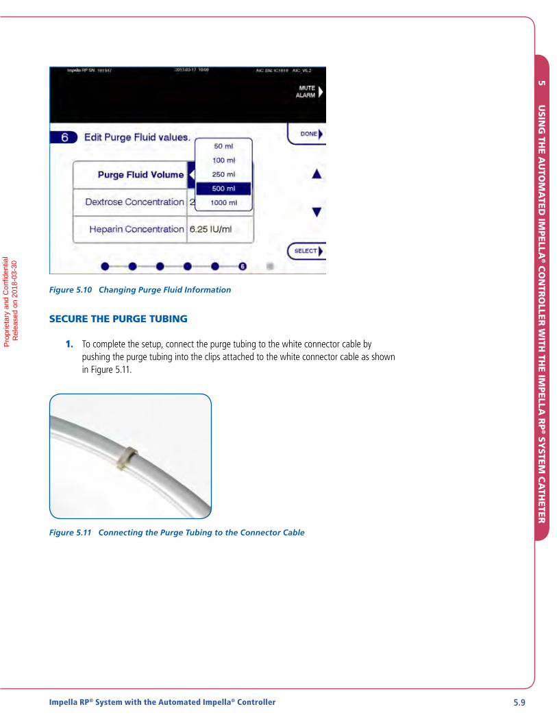
5.9Impella RP® System with the Automated Impella® Controller
Figure 5.10 Changing Purge Fluid Information
SECURE THE PURGE TUBING
1. To complete the setup, connect the purge tubing to the white connector cable by pushing the purge tubing into the clips attached to the white connector cable as shown in Figure 5.11.
Figure 5.11 Connecting the Purge Tubing to the Connector Cable
5
USIN
G TH
E AU
TOM
ATE
D IM
PE
LLA® C
ON
TRO
LLER
WITH
THE IM
PE
LLA R
P® SY
STEM
CA
THETE
RP
ropr
ieta
ry a
nd C
onfid
entia
l
Rel
ease
d on
201
8-03
-30

5.10 Instructions for Use & Clinical Reference Manual (US)
IMPELLA RP SYSTEM CONFIGURATION
Figure 5.12 illustrates the correct configuration of the Impella RP System.
DextroseSolution
Automated Impella® Controller
Purge Cassette
Impella® RP Catheter
D5
Connector Cable
Connect Purge Tubing Directlyto Impella® RP Catheter
Figure 5.12 Impella RP System Configuration
INSERTING THE IMPELLA RP® SYSTEM CATHETER
NOTE – Proper surgical procedures and techniques are the responsibility of the medical professional. The described procedure is furnished for information purposes only. Each physician must evaluate the appropriateness of the procedure based on his or her medical training and experience, the type of procedure, and the type of systems used.
Fluoroscopy is required to guide placement of the Impella RP System Catheter. The small placement guidewire must be reliably observed at all times.
Avoid manual compression of the inlet, outlet, or sensor areas of the cannula assembly.
Do NOT kink or clamp any part of the Impella RP System Catheter.
Handle with care. The Impella RP System Catheter can be damaged during removal from packaging, preparation, insertion, and removal. Do NOT bend, pull, or place excess pressure on the catheter or mechanical components at any time.
Shaded Steps
All shaded steps require sterile technique.
Pro
prie
tary
and
Con
fiden
tial
R
elea
sed
on 2
018-
03-3
0

5.11Impella RP® System with the Automated Impella® Controller
IMPELLA RP SYSTEM CONFIGURATION
Figure 5.12 illustrates the correct configuration of the Impella RP System.
DextroseSolution
Automated Impella® Controller
Purge Cassette
Impella® RP Catheter
D5
Connector Cable
Connect Purge Tubing Directlyto Impella® RP Catheter
Figure 5.12 Impella RP System Configuration
INSERTING THE IMPELLA RP® SYSTEM CATHETER
NOTE – Proper surgical procedures and techniques are the responsibility of the medical professional. The described procedure is furnished for information purposes only. Each physician must evaluate the appropriateness of the procedure based on his or her medical training and experience, the type of procedure, and the type of systems used.
Fluoroscopy is required to guide placement of the Impella RP System Catheter. The small placement guidewire must be reliably observed at all times.
Avoid manual compression of the inlet, outlet, or sensor areas of the cannula assembly.
Do NOT kink or clamp any part of the Impella RP System Catheter.
Handle with care. The Impella RP System Catheter can be damaged during removal from packaging, preparation, insertion, and removal. Do NOT bend, pull, or place excess pressure on the catheter or mechanical components at any time.
Shaded Steps
All shaded steps require sterile technique.
1. Confirm purge fluid is exiting the Impella Catheter.
2. Obtain access to the femoral vein.
3. Insert a 5–8 Fr introducer over the 0.035 inch guidewire (provided) to pre-dilate the vessel.
4. Remove the 5–8 Fr introducer over the 0.035 inch guidewire. Insert the 8 Fr, 12 Fr, 16 Fr, and 20 Fr dilators sequentially, as needed. Remove the 20 Fr dilator and insert the 23 Fr introducer with dilator. While inserting the 23 Fr introducer, hold the shaft of the introducer to advance it into the vein.
5. Administer heparin. When ACT is at least 250 seconds, remove the 23 Fr dilator.
6. Insert a flow-directed balloon-tipped catheter into the 23 Fr introducer and advance it over a guidewire into the left (preferred) or right pulmonary artery, if needed.
7. Remove the 0.035 inch diagnostic guidewire, leaving the diagnostic or balloon-tipped catheter in the pulmonary artery. Form a curve or bend on the 0.027 inch, 260 cm placement guidewire and then insert it.
8. Advance the placement guidewire deep into the LPA until wire prolapses.
9. Remove the diagnostic or balloon-tipped catheter.
10. Wet the cannula with sterile water and backload the catheter onto the placement guidewire. One or two people can load the catheter on the guidewire.
a. Advance the guidewire into the Impella RP® System Catheter and stabilize the cannula between the fingers. The scrub assistant can help stabilize the catheter by holding the catheter proximal to the motor. The physician can focus on advancing the guidewire and, if the cannula needs to be hyperextended, the scrub assistant is available to assist.
11. Advance the catheter through the hemostatic valve into the femoral vein and along the placement guidewire using a fixed-wire technique. Follow the catheter under fluoroscopy, and rotate the catheter as it enters the right ventricle to direct the cannula tip upward and across the pulmonary valve. Position the outlet area of the cannula approximately 4 cm past the pulmonary valve annulus. NOTE: While the entire pump is in the abdominal IVC, calibrate the sensor by pressing the Zero Sensor soft button.
12. Remove the placement guidewire.
13. Confirm position with fluoroscopy.
Use Fluoroscopy for Placement
Impella RP System Catheter performance will be compromised if correct placement cannot be confirmed. While other imaging techniques, such as transesophageal echocardiography (TEE), can help confirm the position of the Impella RP System Catheter after placement, TEE does not allow visualization of the entire catheter assembly and is inadequate for reliably placing the Impella RP System Catheter.
5
USIN
G TH
E AU
TOM
ATE
D IM
PE
LLA® C
ON
TRO
LLER
WITH
THE IM
PE
LLA R
P® SY
STEM
CA
THETE
RP
ropr
ieta
ry a
nd C
onfid
entia
l
Rel
ease
d on
201
8-03
-30

5.12 Instructions for Use & Clinical Reference Manual (US)
POSITIONING AND STARTING THE IMPELLA RP® SYSTEM CATHETER
Retrograde flow will occur from the pulmonary artery back into the inferior vena cava if the Impella RP System Catheter is set at performance level P-0.
When the Impella RP System is properly positioned across the pulmonary valve, but is not yet running, the placement signal will be similar to a pulmonary arterial waveform. After starting the Impella RP, System the amplitude of the placement signal will increase by a factor of 2 to 2.5, depending on the selected performance level.
1. Press the START IMPELLA soft button.
2. Turn the selector knob to increase P-level from P-0 to P-2.
3. Press the selector knob to select the new performance level.
4. Press the YES soft button to confirm after P-level is selected.
5. The catheter operation icon in the lower left corner of the screen begins rotating when the Impella RP System Catheter begins to operate.
6. Increase P-level to P-9 to confirm correct and stable placement. Evaluate the catheter position and remove any excess slack. The catheter inlet area should be in the inferior vena cava and the outlet area in the pulmonary artery. Verify placement with fluoroscopy.
Figure 5.13 Maximum Performance Level
Pro
prie
tary
and
Con
fiden
tial
R
elea
sed
on 2
018-
03-3
0

5.13Impella RP® System with the Automated Impella® Controller
USE OF THE REPOSITIONING SHEATH AND THE 23 FR PEEL-AWAY INTRODUCER
1. Flush the sidearm of the repositioning sheath located on the catheter shaft.
2. Attach a stopcock and flush the repositiong sheath prior to advancing the sheath.
3. Apply manual pressure above the puncture site and remove the 23 Fr peel-away introducer completely from the vein over the catheter shaft.
4. Grasp the two wings and bend back until the valve assembly comes apart. To do this, first stretch then snap the flexible valve mechanism that temporarily holds the two wings together. Continue to peel the two wings until the introducer is completely separated from the catheter shaft. NOTE: Do NOT peel the 23 Fr peel-away introducer over the tip of the repositioning sheath.
5. Place two dead-end caps on the repositioning sheath stopcock to prevent further usage. The sideport should not be used to give medication or draw blood because the blood could potentially clot. Pressure bags should not be connected to the sideport of the repositioning sheath. If a pressure bag is connected, the sideport must have an infusion pump or flow limiting valve in place to control the amount of fluid administered to the patient.
6. Slide the repositioning sheath over the catheter shaft and advance it into the femoral vein to the yellow eyelet.
7. Make sure there is no bleeding at the transition from the repositioning sheath to the femoral vein. Close and dress the wound.
8. Secure the repositioning sheath by suturing it to the skin using the yellow eyelet on the sheath.
9. Attach the anticontamination sleeve to the yellow section of the repositioning sheath. Lock the anchoring ring in place by turning it clockwise. Secure the catheter shaft in place by tightening the connected anchoring ring.
10. Carefully extend the anticontamination sleeve to maximum length and secure the end closest to the blue Impella plug by tightening the anchoring ring.
11. Reposition the catheter as necessary.
To prevent contamination and subsequent infections, always use sterile technique on the insertion site. Follow institutional protocols for prophylaxis of infection for patients on ventricular assist devices and indwelling lines, as well as protocols for surveillance of such patients. If device-related infection occurs, consider each patient’s clinical circumstances when deciding whether to continue Impella support.
5
USIN
G TH
E AU
TOM
ATE
D IM
PE
LLA® C
ON
TRO
LLER
WITH
THE IM
PE
LLA R
P® SY
STEM
CA
THETE
RP
ropr
ieta
ry a
nd C
onfid
entia
l
Rel
ease
d on
201
8-03
-30

5.14 Instructions for Use & Clinical Reference Manual (US)
P-LEVELS
You can select one of ten P-Levels (P-0 to P-9) as shown in Table 5.1. Flow rate is increased by approximately 10% with every additional performance level, but depends on preload and afterload and can vary due to suction or incorrect positioning. Select the lowest performance level that will enable you to achieve the flow rate necessary for patient support.
Table 5.1 P-Level Flow Rates
P-Level *Flow Rate (L/min)P-0 0.0
P-1 0.0 – 1.2
P-2 0.0 – 1.6
P-3 0.0 – 2.0
P-4 1.3 – 2.9
P-5 1.6 – 3.1
P-6 2.4 – 3.5
P-7 3.0 – 4.0
P-8 3.4 – 4.2
P-9 3.9 – 4.4
*Flow rate depends on preload and afterload and can vary due to suction or incorrect positioning.
At P-levels between P-1 and P-6, the Impella RP® System operates with a regularly recurring rapid speed pulse. This minimizes stasis and reduces the risk of thrombosis in the motor area.
SUCTION
If suction is an issue, the flow displayed on the controller may be higher than the actual Impella RP System flow rate. If the suction alarm appears on the controller when the Impella RP System is running at P-levels between P-7 and P-9, decrease P-level as needed to resolve suction.
Retrograde flow
Retrograde flow will occur from the pulmonary artery back into the inferior vena cava if the Impella RP System Catheter is set at P-0. Retrograde flow may also occur at P-1.
Pro
prie
tary
and
Con
fiden
tial
R
elea
sed
on 2
018-
03-3
0
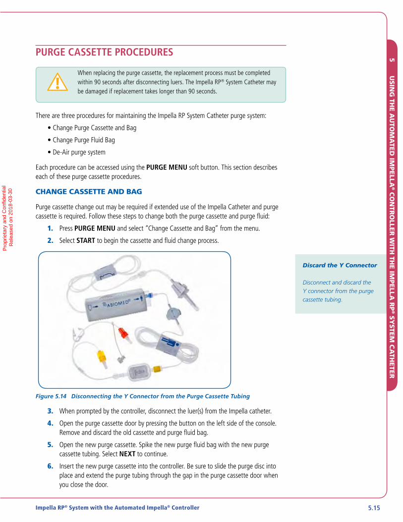
5.15Impella RP® System with the Automated Impella® Controller
PURGE CASSETTE PROCEDURES
When replacing the purge cassette, the replacement process must be completedwithin 90 seconds after disconnecting luers. The Impella RP® System Catheter maybe damaged if replacement takes longer than 90 seconds.
There are three procedures for maintaining the Impella RP System Catheter purge system:
• Change Purge Cassette and Bag
• Change Purge Fluid Bag
• De-Air purge system
Each procedure can be accessed using the PURGE MENU soft button. This section describes each of these purge cassette procedures.
CHANGE CASSETTE AND BAG
Purge cassette change out may be required if extended use of the Impella Catheter and purge cassette is required. Follow these steps to change both the purge cassette and purge fluid:
1. Press PURGE MENU and select “Change Cassette and Bag” from the menu.
2. Select START to begin the cassette and fluid change process.
Figure 5.14 Disconnecting the Y Connector from the Purge Cassette Tubing
3. When prompted by the controller, disconnect the luer(s) from the Impella catheter.
4. Open the purge cassette door by pressing the button on the left side of the console. Remove and discard the old cassette and purge fluid bag.
5. Open the new purge cassette. Spike the new purge fluid bag with the new purge cassette tubing. Select NEXT to continue.
6. Insert the new purge cassette into the controller. Be sure to slide the purge disc into place and extend the purge tubing through the gap in the purge cassette door when you close the door.
Discard the Y Connector
Disconnect and discard the Y connector from the purge cassette tubing.
5
USIN
G TH
E AU
TOM
ATE
D IM
PE
LLA® C
ON
TRO
LLER
WITH
THE IM
PE
LLA R
P® SY
STEM
CA
THETE
RP
ropr
ieta
ry a
nd C
onfid
entia
l
Rel
ease
d on
201
8-03
-30
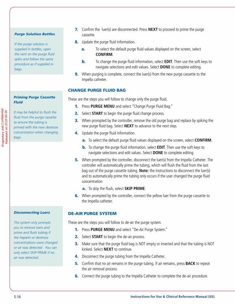
5.16 Instructions for Use & Clinical Reference Manual (US)
7. Confirm the luer(s) are disconnected. Press NEXT to proceed to prime the purge cassette.
8. Update the purge fluid information.
a. To select the default purge fluid values displayed on the screen, select CONFIRM.
b. To change the purge fluid information, select EDIT. Then use the soft keys to navigate selections and edit values. Select DONE to complete editing.
9. When purging is complete, connect the luer(s) from the new purge cassette to the Impella catheter.
CHANGE PURGE FLUID BAG
These are the steps you will follow to change only the purge fluid.
1. Press PURGE MENU and select “Change Purge Fluid Bag.”
2. Select START to begin the purge fluid change process.
3. When prompted by the controller, remove the old purge bag and replace by spiking the new purge fluid bag. Select NEXT to advance to the next step.
4. Update the purge fluid information.
a. To select the default purge fluid values displayed on the screen, select CONFIRM.
b. To change the purge fluid information, select EDIT. Then use the soft keys to navigate selections and edit values. Select DONE to complete editing.
5. When prompted by the controller, disconnect the luer(s) from the Impella Catheter. The controller will automatically prime the tubing, which will flush the fluid from the last bag out of the purge cassette tubing. Note: the instructions to disconnect the luer(s) and to automatically prime the tubing only occurs if the user changed the purge fluid concentration
a. To skip the flush, select SKIP PRIME.
6. When prompted by the controller, connect the yellow luer from the purge cassette to the Impella catheter.
DE-AIR PURGE SYSTEM
These are the steps you will follow to de-air the purge system.
1. Press PURGE MENU and select “De-Air Purge System.”
2. Select START to begin the de-air process.
3. Make sure that the purge fluid bag is NOT empty or inverted and that the tubing is NOT kinked. Select NEXT to continue.
4. Disconnect the purge tubing from the Impella Catheter.
5. Confirm that no air remains in the purge tubing. If air remains, press BACK to repeat the air removal process.
6. Connect the purge tubing to the Impella Catheter to complete the de-air procedure.
Purge Solution Bottles
If the purge solution is supplied in bottles, open the vent on the purge fluid spike and follow the same procedure as if supplied in bags.
Priming Purge Cassette Fluid
It may be helpful to flush the fluid from the purge cassette to ensure the tubing is primed with the new dextrose concentration when changing bags.
Disconnecting Luers
The system only prompts you to remove luers and prime and flush tubing if the heparin or dextrose concentrations were changed or air was detected. You can only select SKIP PRIME if no air was detected.
Pro
prie
tary
and
Con
fiden
tial
R
elea
sed
on 2
018-
03-3
0

5.17Impella RP® System with the Automated Impella® Controller
AIR DETECTED ALERT
During any of the purge system processes above, the controller automatically monitors for air in the system. If air is detected in the system, the controller provides an alert to disconnect the luer(s) as shown in Figure 5.15. Once the luer(s) are disconnected, the controller automatically de-airs the purge system.
Figure 5.15 Air Detected Alert
TROUBLESHOOTING THE PURGE SYSTEM
PURGE PRESSURE LOW
If at any time during the course of support with the Impella RP® System Catheter, the Automated Impella Controller alarms “Purge Pressure Low,” follow the instructions below.
1. Inspect the purge system for leaks.
2. If there are no leaks, change to a purge fluid with a higher dextrose concentration. To do this, open the PURGE MENU menu and select “Change Purge Fluid Bag.” Follow the instructions on the screen. (Refer to “Purge Cassette Procedures” earlier in this section of the manual.)
3. If the pressure stabilizes, no other action is required. If the purge pressure is not stable, proceed to Step 4.
4. If the Purge Pressure Low alarm remains unresolved for more than 20 minutes, there may be a problem with the purge cassette. Replace the purge cassette. (Refer to “Change Cassette and Bag” instructions on the previous page.)
Purge Pressure
Optimal purge pressure is different for every Impella RP System Catheter. Purge pressure can range from 300 mmHg to 1100 mmHg. While purge pressure varies during operation, the Automated Impella Controller automatically maintains purge pressure within an acceptable range for each Impella RP System Catheter.
5
USIN
G TH
E AU
TOM
ATE
D IM
PE
LLA® C
ON
TRO
LLER
WITH
THE IM
PE
LLA R
P® SY
STEM
CA
THETE
RP
ropr
ieta
ry a
nd C
onfid
entia
l
Rel
ease
d on
201
8-03
-30

5.18 Instructions for Use & Clinical Reference Manual (US)
PURGE SYSTEM OPEN
If at any time during the course of support with the Impella RP® System Catheter, the Automated Impella Controller alarms “Purge System Open,” follow the instructions below.
1. Inspect the purge system for leaks.
2. If no leaks are visible, there may be a problem with the purge cassette. Replace the purge cassette. (Refer to instructions earlier in this section of the manual.)
PURGE PRESSURE HIGH AND PURGE SYSTEM BLOCKED
If the purge pressure exceeds 1100 mmHg, the Automated Impella Controller displays the “Purge Pressure High” alarm. If the purge flow stops completely, the controller displays the “Purge System Blocked” alarm. For either event, follow these steps:
1. Inspect the purge system and check the Impella RP System Catheter for kinks in the tubing.
2. Check the dextrose concentration of the purge fluid. Decrease the concentration to 5% if current concentration is higher
3. Replace the purge cassette using the “Change Cassette and Bag” procedure earlier in this section.
4. Monitor Motor Current.
Purge System Open Alarm
This alarm may occur if purge pressure is less than 100 mmHg.
Unresolved Purge Pressure High Alarm
If not resolved by the recommendations provided, high purge pressure—which triggers the “Purge Pressure High” alarm message—could be an indication of a kink in the Impella RP System Catheter. In this case, the motor is no longer being purged and may eventually stop. Monitor motor current and consider replacing the Impella RP System Catheter whenever a rise in motor current is seen.
De-air Procedure
You may run the de-air procedure (described earlier in this section) after changing the dextrose concentration to decrease the amount of time it takes for a change in purge pressure/flow to occur.
Pro
prie
tary
and
Con
fiden
tial
R
elea
sed
on 2
018-
03-3
0

5.19Impella RP® System with the Automated Impella® Controller
PATIENT WEANING
Weaning the patient from the Impella RP System Catheter is at the discretion of the physician. Weaning may occur when right ventricular recovery is suspected and/or the patient is approaching the maximum duration of use for the Impella RP System Catheter. It should be initiated in a step-wise manner, such as described below.
The following weaning protocol is provided as guidance only.
1. Initiate the weaning process by temporarily reducing the Impella RP System Catheter flow to about 2 L/min.
2. Assess right ventricular function. Small changes in right ventricular systolic function as measured by echocardiography may be accompanied by significant improvement in right side forward flow; therefore, it is important to evaluate both echocardiographic evidence of improvement as well as CVP, flow rate, and overall perfusion.
3. Record available information regarding flow rate, CVP, echo parameters, and systemic hemodynamics.
4. After 15–20 minutes at the reduced flow rate, if there are signs of right ventricular recovery and no adverse effects from reduction in flow rate, continue the weaning process by reducing flow rate as tolerated to 0.5 L/min (P-1). At this flow rate there will no longer be any forward flow across the right heart.
5. If the patient is maintained at a low flow rate (<1.5 L/min) for a prolonged period, increase ACT to at least 250 seconds.
REMOVING THE IMPELLA RP® SYSTEM CATHETER
1. Wean the patient by following the steps in the previous section.
2. Leave the Impella RP System in the pulmonary artery at P-2 until ACT drops below 150 OR Reduce the performance level to P-1, pull the catheter into the inferior vena cava (approximately 30 to 40 cm), and wait until ACT drops below 150.
3. When ACT is below 150 seconds and patient hemodynamics remain stable, decrease performance level to P-1, pull the catheter into the inferior vena cava if it is not already there, and stop the motor by reducing the performance level to P-0.
4. Remove initial mattress suture and place new mattress suture, but do not tie off.
5. Remove the Impella RP System Catheter.
6. Tie off mattress suture. Apply pressure until hemostasis is achieved.
7. Disconnect the connector cable from the Automated Impella Controller and turn the controller off by pressing the power switch on the side of the controller for 3 seconds.
Signs of Right Ventricular Recovery
As right-side support is slowly weaned, right ventricular recovery is indicated by preservation of the normal range of left-sided cardiac output as well as by a lack of severe elevation in CVP.
5
USIN
G TH
E AU
TOM
ATE
D IM
PE
LLA® C
ON
TRO
LLER
WITH
THE IM
PE
LLA R
P® SY
STEM
CA
THETE
RP
ropr
ieta
ry a
nd C
onfid
entia
l
Rel
ease
d on
201
8-03
-30

5.20 Instructions for Use & Clinical Reference Manual (US)
Pro
prie
tary
and
Con
fiden
tial
R
elea
sed
on 2
018-
03-3
0

6 CLINICAL EXPERIENCE
STUDY DESIGNS ...........................................................................................6.1
Impella RP System Pivotal Study and CAP Study ............................................... 6.1
Exclusion Criteria .............................................................................................6.2
IMPELLA RP SYSTEM POST APPROVAL STUDY (PAS) .................................. 6.3
Inclusion Criteria ..............................................................................................6.3
Follow-up Schedule (Same for Both Studies) ....................................................6.3
Study Endpoints (Same for Both Studies) ..........................................................6.3
Analysis ...........................................................................................................6.4
ACCOUNTABILITY OF COHORT .................................................................... 6.4
Study Population Demographics and Baseline Characteristics ..........................6.5
SAFETY AND EFFECTIVENESS RESULTS........................................................6.9
Primary Endpoint .............................................................................................6.9
Secondary Endpoints .......................................................................................6.9
OTHER RESULTS ..........................................................................................6.12
Procedural Parameters ................................................................................... 6.12
Subgroup Analysis ......................................................................................... 6.12Pro
prie
tary
and
Con
fiden
tial
R
elea
sed
on 2
018-
03-3
0

Pro
prie
tary
and
Con
fiden
tial
R
elea
sed
on 2
018-
03-3
0

6.1Impella RP® System with the Automated Impella® Controller 6.1
SUMMARY OF PRIMARY CLINICAL STUDYAbiomed has collected clinical data to establish a reasonable assurance of safety and effectiveness of the Impella RP System in patients who developed acute right heart failure or decompensation and required temporary (≤ 14 days) right heart support. The clinical data supporting the PMA approval were pooled from the following three data sets:
• Impella RP System pivotal study: 30 patients
• Impella RP System continued access protocol (CAP) study: 4 patients
• Impella RP System post-approval study (PAS): 26 patients A summary of these clinical studies is presented below.
STUDY DESIGNSIMPELLA RP SYSTEM PIVOTAL STUDY AND CAP STUDY
The Impella RP System pivotal study (also known as the “RECOVER RIGHT” study) and the Impella RP System CAP study had the same study design and were prospective, multi-center, non-randomized studies conducted under investigational device exemption (IDE) G120159. Patients in these two studies were treated between March 22, 2013 and January 19, 2015 at 9 investigational sites in the U.S.
The studies consisted of the following two cohorts:
• Cohort A: Patients who develop right heart failure within 48 hours post-implantation of an FDA approved implantable surgical left ventricular assist device (LVAD).
• Cohort B: Patients who developed cardiogenic shock involving right heart failure or dysfunction post cardiotomy within 48 hours post surgery or post myocardial infarction.
INCLUSION CRITERIA
The study population consisted of consented patients (≥ 18 years of age) who developed RVF either a) during or after durable LVAD implantation (Cohort A) or b) subsequent to post-cardiotomy cardiogenic shock or post myocardial infarction (Cohort B).
RVF was defined as:
• A CI <2.2 l/min/m2 despite continuous infusion of high dose of inotropes and any of the following:
• CVP >15 mmHg or
• CVP/PCWP or LAP >0.63 or
• Moderate to severe global RV dysfunction on echocardiography defined as one of the following criteria: global RV hypokinesis, a TAPSE score of ≤14 mm, right ventricular diameter at base >42mm, right ventricular short axis (or mid cavity) diameter >35mm)
• High dose of inotropes was defined as Dobutamine of ≥10µg/kg/min or equivalent for more than 15 minutes (120 minutes for milrinone) and/or administration of more than one inotrope/vasopressor medication
6
CLIN
ICA
L EX
PE
RIE
NC
EP
ropr
ieta
ry a
nd C
onfid
entia
l
Rel
ease
d on
201
8-03
-30

6.2 Instructions for Use & Clinical Reference Manual (US)
EXCLUSION CRITERIA
Specific to Cohort A:
1. INTERMACS 1 patients (Critical cardiogenic shock patient who is “crashing and burning,” has life-threatening hypotension and rapidly escalating inotropic or pressor support, with critical organ hypoperfusion often confirmed by worsening acidosis and lactate levels)
2. End organ failure (defined as hepatic total bilirubin ≥ 5 mg/dL based on lab data within 24 hours prior to Impella RP System initiation, renal: creatinine ≥ 4 mg/dL based on lab data within the 24 hours prior to Impella RP System initiation)
3. Evidence of acute neurologic injury following LVAD implant
Specific to Cohort B:
1. Patient in profound cardiogenic shock defined as systolic blood pressure< 75 mmHg and CI <1.3 l/min/m2 despite 2 or more high dose of inotropes ± mechanical support or evidence of shock-related end-organ damage, metabolic acidosis (pH 7.1 or less) and not corrected by 100 ml NaHCO3 (1mEq/ml), disseminated intravascular coagulation or clinical evidence of diffuse brain injury or in cardiogenic shock for >24 hours.
2. AMI with mechanical complications (ventricular septal defect, myocardial rupture, papillary muscle rupture)
3. Unsuccessful revascularization of the RCA (TIMI 0.1 post PCI or post-CABG)
General – For Both Cohorts
1. Active infection, two of the following WBC>12,500, positive blood culture, fever
2. RA, RV and/or PA thrombus
3. Prosthetic valves in the right heart (tricuspid or pulmonary valves)
4. Unrepaired atrial septal defect/ patent foramen ovale
5. Structural tricuspid valve disease
6. Severe pulmonary valve stenosis or insufficiency
7. Intolerance to anticoagulant or antiplatelet therapies
8. Severe pulmonary hypertension (PAP>60mmHg)
9. Documented DVT and/or presence of IVC filter
10. Anatomic conditions precluding insertion of the pump or safe use of the device such as severe anomaly of the inferior vena cava, calcification or other disorders of the pulmonary artery wall
11. Pulmonary artery conduit replacement
12. Patient on right side support device or extracorporeal membrane oxygenation
13. Current diagnosis of pulmonary embolism
14. Patient with anatomic anomalies or aortic diseases like aortic dissection, Marfan- Syndrome, Morbus Erdheim-Gsell or others
15. Allergy or intolerance to contrast media
Pro
prie
tary
and
Con
fiden
tial
R
elea
sed
on 2
018-
03-3
0

6.3Impella RP® System with the Automated Impella® Controller
16. Thrombolysis within the previous 30 days or known existing coagulopathy such as thrombocytopenia, heparin induced thrombocytopenia (HIT), hemoglobin diseases such as sickle cell anemia or thalassemia
17. Existing congenital heart disease precluding device insertion
18. Participation in any other clinical investigation that is likely to confound study results or affect study outcome
IMPELLA RP SYSTEM POST APPROVAL STUDY (PAS)The Impella RP System PAS was a prospective, multi-center, non-randomized study conducted as a condition of approval for the original HDE. Patients in the study were treated in the commercial setting between May 27, 2015 and September 24, 2016 at 8 investigational sites in the U.S.
INCLUSION CRITERIA
Enrollment in the Impella RP System PAS was limited to patients who met the approved indicaition of the device under the HDE and who were not contraindicated.
FOLLOW-UP SCHEDULE (SAME FOR BOTH STUDIES)
All patients were scheduled to return for follow-up examinations at 30 and 180 days post device explant.
STUDY ENDPOINTS (SAME FOR BOTH STUDIES)
The primary endpoint was the survival rate at 30 days post device explant or hospital discharge (whichever is longer), or at induction of anesthesia for a longer term therapy, including heart transplant or implantation of a surgical right ventricular assist device (RVAD; as a bridge-to-recovery or bridge-to-transplant).
The secondary safety endpoints were determined by the rates of the following adverse events at 30 days or discharge (whichever is longer), or at induction of anesthesia for a longer term therapy:
• Major bleeding
• Hemolysis
• Pulmonary embolism
• Tricuspid/pulmonary valve dysfunction (defined as tricuspid/pulmonic valve injury resulting in increased valve regurgitation versus baseline)
6
CLIN
ICA
L EX
PE
RIE
NC
EP
ropr
ieta
ry a
nd C
onfid
entia
l
Rel
ease
d on
201
8-03
-30

6.4 Instructions for Use & Clinical Reference Manual (US)
The secondary effectiveness endpoints included the following:
• Central venous pressure (CVP) and cardiac index (CI) improvement post initiation of Impella RP System support
• Decreased use of inotropes during support
• Improvement in left ventricular assist device (LVAD) flow or left ventricle pumping function secondary to the increased venous return by the Impella RP System within 48 hours post implant
ANALYSIS
The three data sets listed above were pooled and analyzed descriptively. The success criterion was based on clinical judgment.
ACCOUNTABILITY OF COHORTA total of 60 subjects were treated in the 3 prospective studies, including 31 subjects (52%) enrolled in Cohort A and 29 subjects (48%) enrolled in Cohort B, as shown in Figure 6.1.
Screening FailuresN=316
• Right ventricular failure (RVG) not present: 161 patients• Cardiac index > 2 L/min/m2: 21 patients• Central venous pressure < 15 mmHg: 12 patients• Lack of insurance coverage: 12 patients• Critical cardiogenic shock: 8 patients• End-organ failure: 7 patients• History of DVT or IVC fi lter present: 6 patients• History of thrombocytopenia or HIT / active infection:
4 patients each• AMI w/ mechanical complication or valve disease:
5 patients• On other RV support or alternative treatment:
24 patients• No informed consent: 17 patients• Other: 35 patients
Screened for Enrollment
N=376
EnrolledN=60
Cohort A
N=31
RVF post left ventricular assist device implantation: 31 patients
Cohort B
N=29
RVF post AMI-CS: 9 patientsRVF post cardiotomy: 13 patientsRVF post transplant: 7 patients
Figure 6.1 Study Flow Schematic
Pro
prie
tary
and
Con
fiden
tial
R
elea
sed
on 2
018-
03-3
0
6.5Impella RP® System with the Automated Impella® Controller
STUDY POPULATION DEMOGRAPHICS AND BASELINE CHARACTERISTICS
The patient baseline characteristics are summarized in Table 6.1. The overall age was 59±15 years old. Among all patients, 88.5% presented with congestive heart failure (CHF), 60% had history of arrhythmia, 57% had ICD or pacemaker implanted, 53% had diabetes, 37.5% had chronic kidney disease, and 20% had prior CVA. Of note, 60% of the patients had received blood products and 78.6% were in NYHA Class IV prior to device implant.
6
CLIN
ICA
L EX
PE
RIE
NC
EP
ropr
ieta
ry a
nd C
onfid
entia
l
Rel
ease
d on
201
8-03
-30
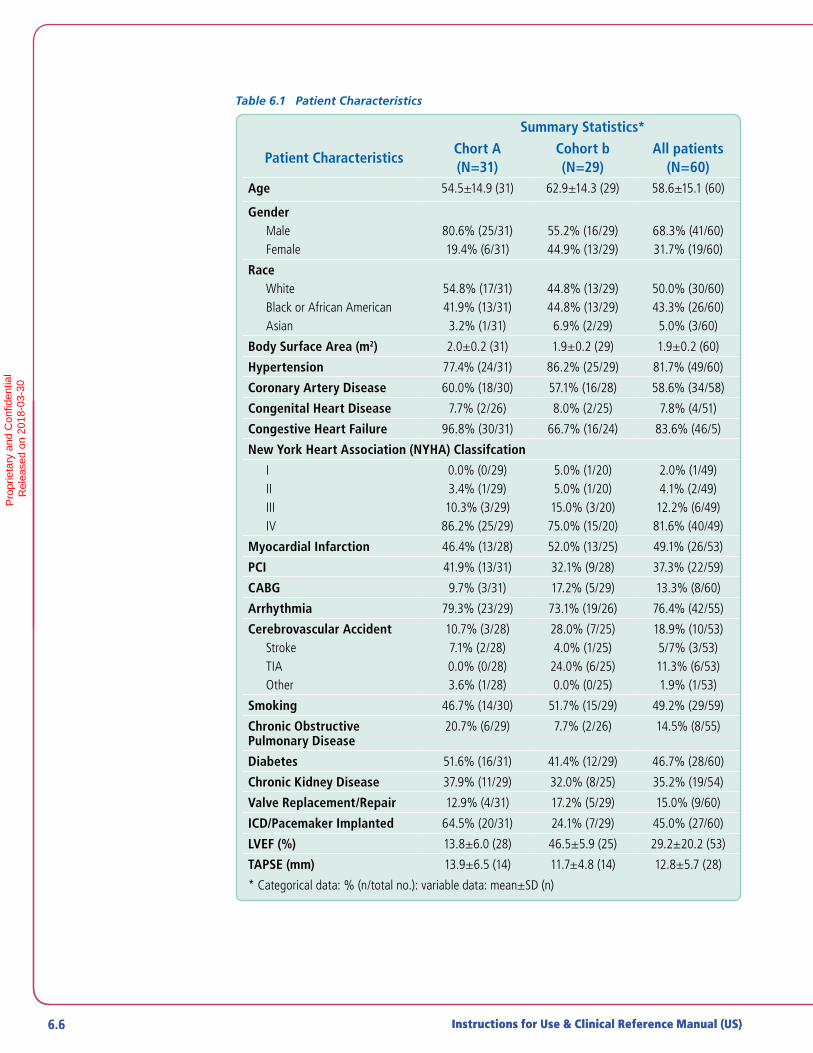
6.6 Instructions for Use & Clinical Reference Manual (US)6.6 Instructions for Use & Clinical Reference Manual (US)
Table 6.1 Patient Characteristics
Summary Statistics*
Patient CharacteristicsChort A(N=31)
Cohort b(N=29)
All patients(N=60)
Age 54.5±14.9 (31) 62.9±14.3 (29) 58.6±15.1 (60)
GenderMaleFemale
80.6% (25/31)19.4% (6/31)
55.2% (16/29)44.9% (13/29)
68.3% (41/60)31.7% (19/60)
RaceWhiteBlack or African AmericanAsian
54.8% (17/31)41.9% (13/31)3.2% (1/31)
44.8% (13/29)44.8% (13/29)6.9% (2/29)
50.0% (30/60)43.3% (26/60)5.0% (3/60)
Body Surface Area (m2) 2.0±0.2 (31) 1.9±0.2 (29) 1.9±0.2 (60)
Hypertension 77.4% (24/31) 86.2% (25/29) 81.7% (49/60)
Coronary Artery Disease 60.0% (18/30) 57.1% (16/28) 58.6% (34/58)
Congenital Heart Disease 7.7% (2/26) 8.0% (2/25) 7.8% (4/51)
Congestive Heart Failure 96.8% (30/31) 66.7% (16/24) 83.6% (46/5)
New York Heart Association (NYHA) Classifcation
IIIIIIIV
0.0% (0/29)3.4% (1/29)
10.3% (3/29)86.2% (25/29)
5.0% (1/20)5.0% (1/20)
15.0% (3/20)75.0% (15/20)
2.0% (1/49)4.1% (2/49)
12.2% (6/49)81.6% (40/49)
Myocardial Infarction 46.4% (13/28) 52.0% (13/25) 49.1% (26/53)
PCI 41.9% (13/31) 32.1% (9/28) 37.3% (22/59)
CABG 9.7% (3/31) 17.2% (5/29) 13.3% (8/60)
Arrhythmia 79.3% (23/29) 73.1% (19/26) 76.4% (42/55)
Cerebrovascular AccidentStrokeTIAOther
10.7% (3/28)7.1% (2/28)0.0% (0/28)3.6% (1/28)
28.0% (7/25)4.0% (1/25)
24.0% (6/25)0.0% (0/25)
18.9% (10/53)5/7% (3/53)11.3% (6/53)1.9% (1/53)
Smoking 46.7% (14/30) 51.7% (15/29) 49.2% (29/59)
Chronic Obstructive Pulmonary Disease
20.7% (6/29) 7.7% (2/26) 14.5% (8/55)
Diabetes 51.6% (16/31) 41.4% (12/29) 46.7% (28/60)
Chronic Kidney Disease 37.9% (11/29) 32.0% (8/25) 35.2% (19/54)
Valve Replacement/Repair 12.9% (4/31) 17.2% (5/29) 15.0% (9/60)
ICD/Pacemaker Implanted 64.5% (20/31) 24.1% (7/29) 45.0% (27/60)
LVEF (%) 13.8±6.0 (28) 46.5±5.9 (25) 29.2±20.2 (53)
TAPSE (mm) 13.9±6.5 (14) 11.7±4.8 (14) 12.8±5.7 (28)
* Categorical data: % (n/total no.): variable data: mean±SD (n)
Pro
prie
tary
and
Con
fiden
tial
R
elea
sed
on 2
018-
03-3
0

6.7Impella RP® System with the Automated Impella® Controller 6.7
The baseline laboratory parameters are provided in Table 6.2. Both kidney and liver functions were reflective of poor end-organ perfusion prior to device insertion.
Table 6.2 Baseline Laboratory Parameters
Summary Statistics*
Baseline CharacteristicsChort A(N=31)
Cohort b(N=29)
All patients(N=60)
White blood cell (WBC) count (103 ) 12.1±6.8 (31) 14.4±9.5 (29) 13.2±8.2 (60)
Platelets count (103 ) 208.1±92.3 (31) 230.4±133.4 (29) 218.9±113.6 (60)
Hemoglobin (g/dL) 10.1±2.0 (31) 10.9±2.0 (29) 10.5±2.0 (60)
Hematocrit (%)(N) 30.9±6.2 (31) 33.3±5.9 (29) 32.1±6.1 (60)
Plasma free hemoglobin (mg/dL) 13.6±11.8 (16) 39.0±59.1 (12) 24.5±40.8 (28)
Blood urea nitrogen (BUN; mg/dL) 27.3±17.2 (31) 31.5±16.6 (29) 29.4±16.9 (60)
Serum creatinine (mg/dL) 1.5±0.6 (31) 1.5±0.7 (29) 1.5±0.6 (60)
Creatinine clearance (mL/min) 76.8±55.1 (23) 68.9±55.2 (22) 73.0±54.7 (45)
Total bilirubin (mg/dL) 1.6±1.1 (29) 1.1±0.6 (29) 1.4±0.9 (58)
Lactate dehydrogenase (LDH; U/L) 539.5±345.9 (24) 715.0±553.6 (14) 604.1±435.2 (38)
* Mean±SD (n)
WBC: White Blood Cells; BUN: Blood Urea Nitrogen; LDH: Lactate Dehydrogenase; BNP: B-type natriuretic peptide
The baseline support and hemodynamic characteristics are summarized in Table 6.3. All patients enrolled presented with right ventricular failure and poor hemodynamics at the time of implant, despite high dose of inotropes/pressors.
6
CLIN
ICA
L EX
PE
RIE
NC
EP
ropr
ieta
ry a
nd C
onfid
entia
l
Rel
ease
d on
201
8-03
-30

6.8 Instructions for Use & Clinical Reference Manual (US)6.8 Instructions for Use & Clinical Reference Manual (US)
Table 6.3 Baseline Support and Hemodynamic Characteristics
Summary Statistics*
Support and Hemodynamic Characteristics
Chort A(N=31)
Cohort b(N=29)
All patients(N=60)
Number of inotropes/pressors (prior to device insertion)
3.6±.2 (31) 3.1±1.3 (28) 3.4±1.2 (59)
Hemodynamics (prior to device insertion)
Cardiac index (L/min/m2 ) 1.8±0.5 (31) 1.9±0.6 (28) 1.9±0.5 (59)
Cardiac output (L/min) 3.9±1.4 (31) 3.8±1. 3 (28) 3.9±1.3 (59)
Pulminary Capillary Wedge pressure/left arterial pressure (mmHg)
14.5±4.6 (8) 20.4±8.5 (8) 17. 4±7.3 (16)
Right arterial pressure/central venous pressure (mmHg)
18.42±4.79 (31) 19.84±5.83 (29) 19.1±5.3 (60)
Pulmonary artery pressure: Systolic (mmHg)
39.4±12.1 (29) 39.8±10.3 (26) 39.6±11.1 (55)
Pulmonary artery pressure: Diastolic (mmHg)
23.9±11.6 (31) 21.2±7.8 (27) 22.5±9.9 (58)
Mean arterial Ppressure (mmHg) 75.6±12.4 (24) 65.9±16.3 (24) 70.7±15.1 (48)
Heart rate (BPM) 91.9±19.7 (28) 86.1±18.0 (28) 89.0±18.9 (56)
LVAD flow (L/min; Cohort A only) 4.0±0.7 (19) N/A 4.0±0.7 (19)
* Mean±SD (n)Pro
prie
tary
and
Con
fiden
tial
R
elea
sed
on 2
018-
03-3
0

6.9Impella RP® System with the Automated Impella® Controller 6.9
SAFETY AND EFFECTIVENESS RESULTSPRIMARY ENDPOINT
The primary endpoint of survival at 30 days or discharge post device removal (whichever is longer), or at induction of anesthesia for the next longer-term therapy (i.e., heart transplant or implantation of a surgical RVAD) was achieved in 73.3% of the patients, with 77.4% in cohort A and 69.0% in cohort B, as shown in Table 6.4. It is important to note that all patients discharged from the hospital (70% of all patients) recovered their right heart function and were discharged without any right ventricular mechanical support.
Table 6.4 Patient Survival Outcomes
Summary Statistics*
EventChort A(N=31)
Cohort b(N=29)
All patients(N=60)
Alive at 30 days/discharge/next therapy
77.4% (24/31) 69.0% (20/29) 73.3% (44/60)
Alive at next longer term therapy 16.1% (5/31) 6.9% (2/29) 11.7% (7/60)
Alive at 30 days 77.4% (24/31) 65.5% (19/29) 71.7% (43/60)
Alive at discharge 71.0% (22/31) 69.0% (20/29) 70.0% (42/60)
Right ventricle recovered (discharged
39.4±12.1 (29) 39.8±10.3 (26) 39.6±11.1 (55)
without RVAD) 100% (22/22) 100% (20/20) 100% (42/42)
Mean arterial Ppressure (mmHg) 75.6±12.4 (24) 65.9±16.3 (24) 70.7±15.1 (48)
Heart rate (BPM) 91.9±19.7 (28) 86.1±18.0 (28) 89.0±18.9 (56)
LVAD flow (L/min; Cohort A only) 4.0±0.7 (19) N/A 4.0±0.7 (19)
*% (n/total no.)
SECONDARY ENDPOINTS
Safety EndpointsThe secondary safety endpoint results are summarized in Table 6.5, which were measured at hospital discharge or to induction of anesthesia to a longer term therapy.
Table 6.5 Secondary Safety Endpoints Results
Summary Statistics*
EventChort A(N=31)
Cohort b(N=29)
All patients(N=60)
Major bleeding 54.8% (17/31) 41.4% (12/29) 48.3% (29/60)
Hemolysis 29.0% (9/31) 24.1% (7/29) 26.7% (16/60)
Pulmonary embolism 0.0% (0/31) 0.0% (0/29) 0.0% (0/60)
*% (n/total no.)
6
CLIN
ICA
L EX
PE
RIE
NC
EP
ropr
ieta
ry a
nd C
onfid
entia
l
Rel
ease
d on
201
8-03
-30

6.10 Instructions for Use & Clinical Reference Manual (US)
Effectiveness Endpoints
Central venous pressure and cardiac index:
The central venous pressure and cardiac index changes over time are shown in Figures 6.2 and 6.3, respectively. The central venous pressure decreased from 19 ± 0.8 to 13 ± 1 mmHg post support; the cardiac index increased from 1.9 ± 0.1 to 3.1±0.2 L/min/m2 post support. In addition, both the central venous pressure and the cardiac index remained stable post- explant of the Impella RP System.
22
20
18
16
14
12
10
8
6
4
2
0
Cent
ral V
enou
s Pr
essu
re (m
mHg
)
Pre Support On Support Post Explant
Figure 6.2: Central Venous Pressure Change Over Time
4
3
2
1
0
Card
iac
Inde
x (I/
min
/m^
2)
Pre Support On Support Post Explant
Figure 6.3: Cardiac Index Change Over Time
Pro
prie
tary
and
Con
fiden
tial
R
elea
sed
on 2
018-
03-3
0

6.11Impella RP® System with the Automated Impella® Controller
LVAD flow:
The LVAD flow in Cohort A patients is shown in Figure 6.4. The flow increased from 4.0 ± 0.2 L/min to 4.6 ± 0.1 L/min post support.
Figure 6.4: LVAD Flow Change from Baseline to On support
4
5
6
3
2
1
0
Aver
age
LVAD
FLo
w (L
/min
)
Pre Support On Support
Inotrope and pressor uses during support:
The inotrope and pressor uses during support are shown in Figure 6.5. A rapid decrease of such uses were seen post initiation of Impella RP System support.
4
5
3
2
1
02 4 6 8 10 12 14 16 17 20 22 24 26 28 30
Aver
age
# of
inot
rope
s an
d pr
esso
rs u
sage
Baseline
Avg. duration of support
Days
Figure 6.5: Inotrope and Pressor Uses during Support
6
CLIN
ICA
L EX
PE
RIE
NC
EP
ropr
ieta
ry a
nd C
onfid
entia
l
Rel
ease
d on
201
8-03
-30

6.12 Instructions for Use & Clinical Reference Manual (US)
OTHER RESULTSPROCEDURAL PARAMETERS
The procedural parameters are summarized in Table 6.6.
Table 6.6: Procedural Parameters
Summary Statistics*
Procedural ParametersChort A(N=31)
Cohort b(N=29)
All patients(N=60)
Side of implantation
Left femoral vein 0.0% (0/31) 6.9% (2/29) 3.3% (2/60)
Right femoral vein 100.0% (31/31) 93.1% (27/29) 96.7% (58/60)
Estimated blood loss during introducer insertion
<25 mL 86.4% (19/22) 88.5% (23/26) 87.5% (42/48)
25-50 mL 9.1% (2/22) 7.7% (2/26) 8.3% (4/48)
>100 mL 4.5% (1/22) 3.8% (1/26) 4.2% (2/48)
Estimated blood loss during catheter placement
<25mL 66.7% (14/21) 46.2% (12/26) 55.3% (26/47)
25-50 mL 28.6% (6/21) 38.5% (10/26) 34.0% (16/47)
>100 mL 4.8% (1/21) 7.7% (2/26) 6.4% (3/47)
Duration of support (hours) 101.2±66.0 (21) 81.9±49.1 (29) 90.0±57.0 (50)
Average device flow (L/min) 3.2±0.4 (23) 3.2±0.4 (27) 3.2±0.4 (50)
Categorical data: % (n/total no.); variable data: mean±SD (n)
SUBGROUP ANALYSIS
Gender AnalysisThe outcomes by gender were also examined. A trend towards higher mortality was observed in female patients; the rate of the other adverse events appeared comparable between genders. However, the small sample size and the multiple cohorts studied prevent any conclusions based on gender.
Pro
prie
tary
and
Con
fiden
tial
R
elea
sed
on 2
018-
03-3
0

ALARMS OVERVIEW ..................................................................................... 7.1
Alarm Levels .................................................................................................... 7.1
Alarm Display .................................................................................................. 7.2
Mute Alarm Function ....................................................................................... 7.2
ALARM MESSAGE SUMMARY ......................................................................7.3
7 AUTOMATED IMPELLA® CONTROLLER ALARMS
Pro
prie
tary
and
Con
fiden
tial
R
elea
sed
on 2
018-
03-3
0

Pro
prie
tary
and
Con
fiden
tial
R
elea
sed
on 2
018-
03-3
0
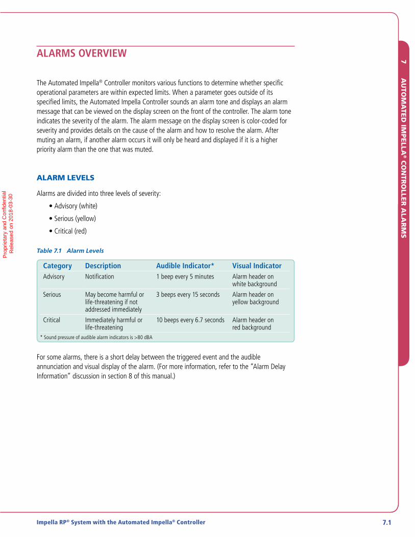
7.1Impella RP® System with the Automated Impella® Controller 7.1
ALARMS OVERVIEW
The Automated Impella® Controller monitors various functions to determine whether specific operational parameters are within expected limits. When a parameter goes outside of its specified limits, the Automated Impella Controller sounds an alarm tone and displays an alarm message that can be viewed on the display screen on the front of the controller. The alarm tone indicates the severity of the alarm. The alarm message on the display screen is color-coded for severity and provides details on the cause of the alarm and how to resolve the alarm. After muting an alarm, if another alarm occurs it will only be heard and displayed if it is a higher priority alarm than the one that was muted.
ALARM LEVELS
Alarms are divided into three levels of severity:
• Advisory (white)
• Serious (yellow)
• Critical (red)
Table 7.1 Alarm Levels
Category Description Audible Indicator* Visual IndicatorAdvisory Notification 1 beep every 5 minutes Alarm header on
white background
Serious May become harmful or life-threatening if not addressed immediately
3 beeps every 15 seconds Alarm header on yellow background
Critical Immediately harmful or life-threatening
10 beeps every 6.7 seconds Alarm header on red background
* Sound pressure of audible alarm indicators is >80 dBA
For some alarms, there is a short delay between the triggered event and the audible annunciation and visual display of the alarm. (For more information, refer to the “Alarm Delay Information” discussion in section 8 of this manual.)
7
AU
TOM
ATE
D IM
PE
LLA® C
ON
TRO
LLER
ALA
RM
SP
ropr
ieta
ry a
nd C
onfid
entia
l
Rel
ease
d on
201
8-03
-30

7.2 Instructions for Use & Clinical Reference Manual (US)7.2 Instructions for Use & Clinical Reference Manual (US)
ALARM DISPLAY
The alarm window is located in the upper left region of the display screen on the front of the Automated Impella® Controller (see Figure 7.1). Alarms are listed in order of priority, with the highest priority alarm at the top. Up to three alarms may be displayed at one time. The colored background behind the highest priority alarm will alternate between two shades of that color. The white panel displayed to the right of the alarm header contains instructions for resolving the alarm condition. The instructions should be followed in the order given.
Figure 7.1 Alarm Window
MUTE ALARM FUNCTION
Pressing the MUTE ALARM button on the upper right of the Automated Impella Controller display screen will silence the audible alarm indicator for 2 minutes (for red or yellow alarms) or 5 minutes (for white advisory alarms). When an alarm is silenced, the words “MUTE ALARM” next to the button are replaced by the mute alarm indicator, a crossed-out bell icon (as shown in Figure 7.1).
ALARM HISTORY SCREEN
The alarm history screen may be accessed through the MENU. This screen contains a log of the alarms that occurred during the case. This log is maintained when the Automated Impella Controller is powered down or after a power failure. The controller does, however, maintain a long-term log that is saved after the Automated Impella Controller is powered down or after a power failure and this information may be downloaded by Abiomed personnel.
Alarms That Resolve On Their Own
The audible indicator will shut off if an alarm condition is resolved before you press MUTE ALARM. The visual message, however, will continue to be displayed, with the alarm header on a gray background, for 20 minutes or until you press MUTE ALARM. This allows you to identify the alarm that occurred.
Pro
prie
tary
and
Con
fiden
tial
R
elea
sed
on 2
018-
03-3
0

7.3Impella RP® System with the Automated Impella® Controller 7.3
ALARM MESSAGE SUMMARY
Table 7.2 briefly describes all of the alarm messages that may appear on the Automated Impella® Controller when used with the Impella RP® System Catheter.
Table 7.2 Automated Impella Controller Alarm Messages
7
AU
TOM
ATE
D IM
PE
LLA® C
ON
TRO
LLER
ALA
RM
S
Severity Alarm Header Action Cause
Crit
ical
Ala
rms
Air in Purge System The purge system has stopped.Press the PURGE MENU soft key thenselect De-Air Purge System.
There is air in the purge tubing.
Battery Critically Low Plug controller into AC power. Battery power has 15% remaining capacity.
Battery Failure Plug controller into AC power. One of the batteries has failed.
Battery Failure 1. Plug controller into AC power. 2. Press switch located on the underside of
the controller.3. Switch to backup controller.
A battery switch is turned off or there is a malfunction of the switch.
Battery Temperature High Switch to backup controller. Battery temperature is greater than 60°C.
Complete Procedure 1. Follow the steps on the screen or2. Exit the procedure
The Complete Procedure serious alarm (yellow; see next page) is active and the user has not responded for an additional 2 minutes.
Controller Failure The purge system has stopped. Switch to backup controller.
The controller has detected a purge pressure sensor defect and has stopped the purge system.
Controller Failure Switch to backup controller. There is a problem with the controller electronics.
Emergency Shutdown Imminent
Release ON/OFF push button. Power switch pressed for 15 seconds while Impella RP System Catheter still connected.
Impella Disconnected 1. Check cable connection to console. 2. Check Impella connection to cable.
Running Impella RP System Catheter disconnected.
Impella Failure Replace Impella. There is a problem with the Impella RP System Catheter motor.
Impella Stopped 1. Replace white connector cable.2. Switch to backup controller.3. Replace Impella pump.
There is a problem with the electronics.
Pro
prie
tary
and
Con
fiden
tial
R
elea
sed
on 2
018-
03-3
0

7.4 Instructions for Use & Clinical Reference Manual (US)7.4 Instructions for Use & Clinical Reference Manual (US)
Table 7.2 Automated Impella® Controller Alarm Messages (continued)
Severity Alarm Header Action CauseCr
itic
al A
larm
sImpella Stopped 1. Restart Impella.
2. Replace Impella after 3rd unsuccessful restart attempt
There may be a mechanical or electrical problem in the Impella RP System Catheter.
Impella Stopped
Controller Failure
Switch to backup controller. There is a problem with the controller electronics.
Impella Stopped Motor Current High
1. Restart Impella.2. Replace Impella after 3rd
unsuccessful restart attempt.
There is a problem with the Impella RP® System Catheter motor.
Impella Stopped
Retrograde Flow
To prevent retrograde flow, restart Impella or withdraw pump from ventricle.
Impella RP System Catheter is not running; possible retrograde flow through Impella RP System Catheter.
Purge Disc Not Detected Re-insert Purge Disc The controller is not detecting that the purge disc is clicked into the front of the controller.
Purge Pressure High Decrease concentration of dextrose in the purge solution.
Purge pressure is ≥1100mmHg with the purge flow <2 mL/hr.
Purge Pressure Low 1. Check purge system tubing for leaks.2. Increase concentration of dextrose in
the purge solution.3. Replace purge cassette.
Purge pressure has dropped below 300 mmHg with the purge flow 30 mL/hr for 30 seconds or longer.
Purge System Blocked 1. Check all purge system tubing for kinks or blockages.
2. Decrease concentration of dextrose in the purge solution.
Purge flow has dropped below 1 mL/hr.Kinked or blocked purge connecting tube.Kinked or blocked purge lumen in Impella RP System Catheter.
Purge System Failure 1. Replace purge cassette.2. Switch to backup controller.
There is a problem with the purge cassette or the purge unit driver.
Purge System Open 1. Check the purge system tubing for open connections or leaks.
2. Replace purge cassette.
Purge pressure has dropped below 100 mmHg for 20 seconds or longer.
Retrograde Flow Check for high afterload pressure. Reverse flow detected at high motor speed.
Pro
prie
tary
and
Con
fiden
tial
R
elea
sed
on 2
018-
03-3
0
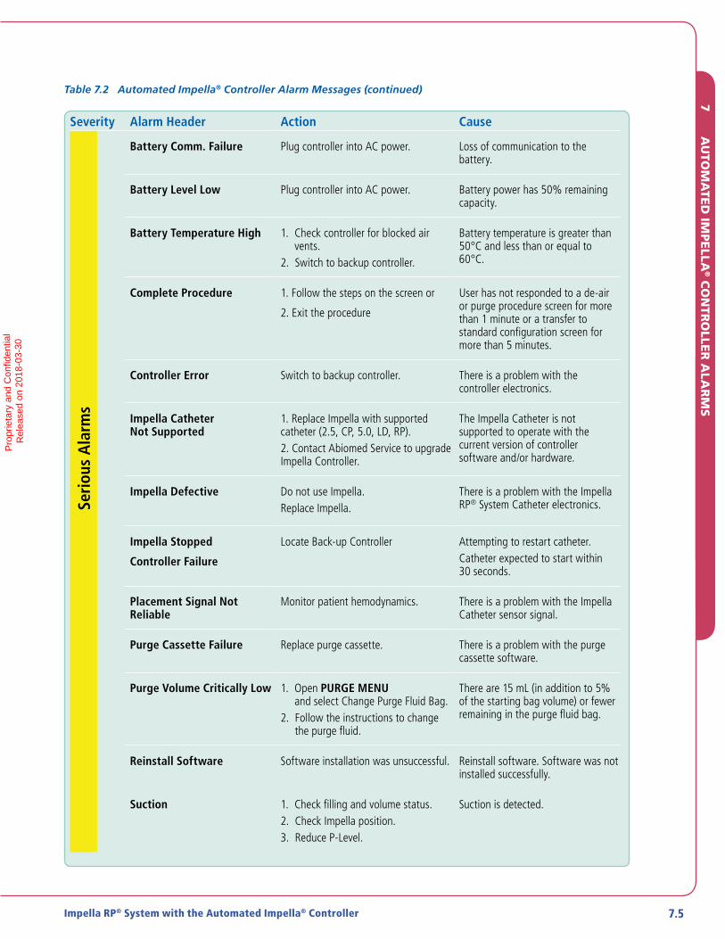
7.5Impella RP® System with the Automated Impella® Controller 7.5
Table 7.2 Automated Impella® Controller Alarm Messages (continued)
Severity Alarm Header Action Cause
Seri
ous
Ala
rms
Battery Comm. Failure Plug controller into AC power. Loss of communication to the battery.
Battery Level Low Plug controller into AC power. Battery power has 50% remaining capacity.
Battery Temperature High 1. Check controller for blocked air vents.
2. Switch to backup controller.
Battery temperature is greater than 50°C and less than or equal to 60°C.
Complete Procedure 1. Follow the steps on the screen or
2. Exit the procedure
User has not responded to a de-air or purge procedure screen for more than 1 minute or a transfer to standard configuration screen for more than 5 minutes.
Controller Error Switch to backup controller. There is a problem with the controller electronics.
Impella Catheter Not Supported
1. Replace Impella with supported catheter (2.5, CP, 5.0, LD, RP).2. Contact Abiomed Service to upgrade Impella Controller.
The Impella Catheter is not supported to operate with the current version of controller software and/or hardware.
Impella Defective Do not use Impella.Replace Impella.
There is a problem with the Impella RP® System Catheter electronics.
Impella Stopped
Controller Failure
Locate Back-up Controller Attempting to restart catheter.Catheter expected to start within 30 seconds.
Placement Signal Not Reliable
Monitor patient hemodynamics. There is a problem with the Impella Catheter sensor signal.
Purge Cassette Failure Replace purge cassette. There is a problem with the purge cassette software.
Purge Volume Critically Low 1. Open PURGE MENU and select Change Purge Fluid Bag.
2. Follow the instructions to change the purge fluid.
There are 15 mL (in addition to 5% of the starting bag volume) or fewer remaining in the purge fluid bag.
Reinstall Software Software installation was unsuccessful. Reinstall software. Software was not installed successfully.
Suction 1. Check filling and volume status.2. Check Impella position.3. Reduce P-Level.
Suction is detected.
7
AU
TOM
ATE
D IM
PE
LLA® C
ON
TRO
LLER
ALA
RM
SP
ropr
ieta
ry a
nd C
onfid
entia
l
Rel
ease
d on
201
8-03
-30
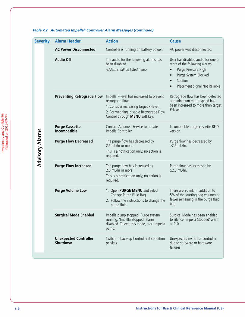
7.6 Instructions for Use & Clinical Reference Manual (US)
Table 7.2 Automated Impella® Controller Alarm Messages (continued)
Severity Alarm Header Action CauseA
dvis
ory
Ala
rms
AC Power Disconnected Controller is running on battery power. AC power was disconnected.
Audio Off The audio for the following alarms has been disabled.<Alarms will be listed here>
User has disabled audio for one or more of the following alarms:• Purge Pressure High• Purge System Blocked• Suction• Placement Signal Not Reliable
Preventing Retrograde Flow Impella P-level has increased to prevent retrograde flow. 1. Consider increasing target P-level.2. For weaning, disable Retrograde Flow Control through MENU soft key.
Retrograde flow has been detected and minimum motor speed has been increased to more than target P-level.
Purge Cassette Incompatible
Contact Abiomed Service to update Impella Controller.
Incompatible purge cassette RFID version.
Purge Flow Decreased The purge flow has decreased by 2.5 mL/hr or more.This is a notification only; no action is required.
Purge flow has decreased by ≥2.5 mL/hr.
Purge Flow Increased The purge flow has increased by 2.5 mL/hr or more.This is a notification only; no action is required.
Purge flow has increased by ≥2.5 mL/hr.
Purge Volume Low 1. Open PURGE MENU and select Change Purge Fluid Bag.
2. Follow the instructions to change the purge fluid.
There are 30 mL (in addition to 5% of the starting bag volume) or fewer remaining in the purge fluid bag.
Surgical Mode Enabled Impella pump stopped. Purge system running. ‘Impella Stopped’ alarm disabled. To exit this mode, start Impella pump.
Surgical Mode has been enabled to silence ‘Impella Stopped’ alarm at P-0.
Unexpected Controller Shutdown
Switch to back-up Controller if condition persists.
Unexpected restart of controller due to software or hardware failures
Pro
prie
tary
and
Con
fiden
tial
R
elea
sed
on 2
018-
03-3
0

TERMINOLOGY, ABBREVIATIONS, AND SYMBOLS ......................................8.1
AUTOMATED IMPELLA CONTROLLER MECHANICAL SPECIFICATIONS ....... 8.3
AUTOMATED IMPELLA CONTROLLER ELECTRICAL SPECIFICATIONS .......... 8.3
EQUIPMENT DESIGN ................................................................................... 8.4
EQUIPMENT CLASSIFICATIONS ................................................................... 8.4
FEDERAL COMMUNICATIONS COMMISSION (FCC) NOTICE ....................... 8.5
ELECTROMAGNETIC COMPATIBILITY .......................................................... 8.5
TRANSPORT BETWEEN HOSPITALS ............................................................ 8.11
Guidelines for Patient Transport ..................................................................... 8.11
Important Transport Considerations ............................................................... 8.11
FAA Advisory ................................................................................................. 8.12
TRANSPORT WITHIN THE HOSPITAL ..........................................................8.12
VGA MONITOR CONNECTION ....................................................................8.13
ALARM DELAY INFORMATION ...................................................................8.13
PATIENT ENVIRONMENT ............................................................................8.14
USE ENVIRONMENT....................................................................................8.14
WHITE CONNECTOR CABLE ........................................................................8.14
IMPELLA RP SYSTEM CATHETER PARAMETERS .........................................8.15
CLEANING ..................................................................................................8.16
STORING THE AUTOMATED IMPELLA CONTROLLER ..................................8.16
RETURNING AN IMPELLA RP SYSTEM CATHETER TO ABIOMED (UNITED STATES) .......................................................................8.16
8 GENERAL SYSTEM INFORMATION
Pro
prie
tary
and
Con
fiden
tial
R
elea
sed
on 2
018-
03-3
0

Pro
prie
tary
and
Con
fiden
tial
R
elea
sed
on 2
018-
03-3
0

8.1Impella RP® System with the Automated Impella® Controller
TERMINOLOGY, ABBREVIATIONS, AND SYMBOLSTable 8.1 Terminology and Abbreviations
Catheter serial numberIdentification number of the Impella RP System Catheter; stated on the package label, on the blue Impella plug, and the Automated Impella Controller display screen
Dextrose and GlucoseThe terms “dextrose” and “glucose” are used interchangeably to refer to the solution used as purge fluid for the Impella RP System
Hz Hertz
Motor housing Enclosure of the Impella RP System Catheter motor
PumpCentral delivery unit of the Impella RP System Catheter, consisting of the motor, motor housing, cannula with inlet and outlet, and pigtail at the tip
Purge pressure Pressure present in the Impella RP System Catheter and in the infusion line
Purge system Impella purge cassette used for rinsing the Impella RP System Catheter
Retrograde flow Reverse flow through the cannula when the Impella RP System Catheter is at a standstill (eg, regurgitation)
V Volt
VA Volt ampere (Watt)
Table 8.2 Symbols
Caution; follow instructions for use
Defibrillator-proof type CF equipment
Keep dry
Storage temperature (eg, 10°C to 30°C)
Declares conformity with directive 93/42/EEC for medical devices
2014-10-01Date of manufacture (eg, October 1, 2014)
Protect from sunlight
Symbol for lot designation; the manufacturer’s lot designation must be stated after the LOT symbol
8
GE
NE
RA
L SY
STE
M IN
FOR
MA
TION
Pro
prie
tary
and
Con
fiden
tial
R
elea
sed
on 2
018-
03-3
0

8.2 Instructions for Use & Clinical Reference Manual (US)
Table 8.2 Symbols (continued)
REF 123456 Abiomed part number (eg, part number 123456)
SN 123456 Manufacturer’s serial number (eg, serial number 123456)
Non Sterile! The product is not sterile
2016-06-01Use-by date (eg, use before June 1, 2016)
Do not reuse
Sterilized using ethylene oxide
Electric scrap; must be disposed of separately. Must not be disposed of as domestic waste.
Protective Earth
ON / OFF
Alternating current (AC) only
Equipotentiality
Fuse
Non-ionizing electromagnetic radiation
USB port
CAT 5 Port (Ethernet)
MR Unsafe
Do Not Flush Do Not Flush
Glucose Glucose
Pro
prie
tary
and
Con
fiden
tial
R
elea
sed
on 2
018-
03-3
0

8.3Impella RP® System with the Automated Impella® Controller
AUTOMATED IMPELLA CONTROLLER MECHANICAL SPECIFICATIONSTable 8.3 Mechanical specifications for the Automated Impella Controller
Parameter SpecificationTemperature Operating: 10°C to 40°C (50°F to 104°F)
Storage: –15°C to 50°C (5°F to 122°F)
Relative Humidity Operating: 95%Storage: 95%
Atmospheric Pressure Operating: 8000 ft (750 hPa) to –1000 ft (1050 hPa)Storage: 18,000 ft (500 hPa) to –1000 ft (1050 hPa)
Dimensions Height: 351 mm (13.8 in)Width: 443 mm (17.4 in)Depth: 236 mm (9.3 in)
Dimensions – Packaged
Height: 508 mm (20.0 in)Width: 559 mm (22.0 in)Depth: 406 mm (15.0 in)
Weight Maximum: 11.8 kg (26.1 lbs)
Weight – Packaged Maximum: 13.6 kg (30 lbs)
Maintenance and repair interval
12 months(Work must be performed by technicians authorized by Abiomed)
AUTOMATED IMPELLA CONTROLLER ELECTRICAL SPECIFICATIONSTable 8.4 Electrical specifications for the Automated Impella Controller
AC operation 100-230 V AC (nominal); 47-63 Hz; 1.1 A
Internal battery operation 14.4 V DC (nominal); lithium ion
Characteristic valuesMax. power consumption under load9.7 fusesRunning time without AC power with fully charged batteries
120 VA2 Amp. 250 V. 5 mm x 20 mm, slow-blow fusesAt least 60 minutes (charging duration of at least 5 hours)
Electrical system Installation in accordance with pertinent regulations is required for use in medical facilities (eg, IEC stipulations).
8
GE
NE
RA
L SY
STE
M IN
FOR
MA
TION
Pro
prie
tary
and
Con
fiden
tial
R
elea
sed
on 2
018-
03-3
0

8.4 Instructions for Use & Clinical Reference Manual (US)
EQUIPMENT DESIGN
The Automated Impella Controller conforms to the applicable requirements of the following standards:
• IEC 60601-1: 2012 Edition 3.1 Medical Electrical Equipment Part 1: General Requirements for Basic Safety and Essential Performance
• CSA C22.2#60601-1 (2014) Ed:3 Medical Electrical Equipment Part 1: General Requirements for Basic Safety and Essential Performance
• AAMI ES60601-1:2005 +C1:A2 Medical Electrical Equipment Part 1: General Requirements for Basic Safety and Essential Performance
• IEC 60601-1-2:2014 Edition 4, Medical Electrical Equipment – Part 1-2: General Requirements for Basic Safety and Essential Performance – Collateral Standard: Electromagnetic Disturbances – Requirements and Tests
• IEC 60601-1-6:2010, AMD1:2013 Medical Electrical Equipment – Part 1-6: General Requirements for Safety – Collateral Standard: Usability
• IEC 60601-1-8:2006, AM1:2012 Medical Electrical Equipment – Part 1-8: General Requirements for Safety – Collateral Standard: General Requirements, Tests and Guidance for Alarm Systems in Medical Electrical Equipment and Medical Electrical Systems
• IEC 62304:2015 Medical Device Software - Software Life-cycle processes
• RTCA DO160G Environmental Conditions and Test Procedures for Airborn Equipment
• AIM 7351731 Medical Electrical Equipment and System Electromagnetic Immunity test for Exposure to Radio Frequency Identification Readers
EQUIPMENT CLASSIFICATIONSTable 8.5 Equipment classifications
Type of protection against electric shock
IEC 60601-1: Class I degree of protection: CF defibrillation-proof and internally powered. Relies not only on basic insulation against shock but also includes additional protection. Accomplished by providing means for connecting the equipment to the protective earth conductor of the fixed wiring of the installation in a way that prevents accessible metal parts from becoming live if basic insulation fails.
Degree of protection against electric shock for Automated Impella Controller
Class I Equipment
Mode of operation Continuous
Degree of protection against explosion hazard
Not suitable for use in the presence of a flammable anesthetic mixture with air or with oxygen or nitrous oxide. Also not suitable for use in an oxygen-enriched atmosphere.
Degree of protection against harmful ingress of water
IEC 60529: IPX1 protected against dripping water.
Pro
prie
tary
and
Con
fiden
tial
R
elea
sed
on 2
018-
03-3
0

8.5Impella RP® System with the Automated Impella® Controller
FEDERAL COMMUNICATIONS COMMISSION (FCC) NOTICE
This device complies with Part 15 of the FCC Rules. Operation is subject to the following two conditions:
1. This device may not cause harmful interference.
2. This device must accept any interference received, including interference that may cause undesired operation.
Changes or modifications not expressly approved by Abiomed, Inc. could void the user’s authority to operate this device.
NOTE: “Harmful interference” is defined by the FCC as follows: Any emission, radiation or induction that endangers the functioning of a radio navigation service or of other safety services or seriously degrades, obstructs or repeatedly interrupts a radiocommunications service operating in accordance with FCC rules.
ELECTROMAGNETIC COMPATIBILITY
Medical electrical equipment needs special precautions regarding EMC and needs to be installed and put into service according to the electromagnetic compatibility (EMC) information provided in this document.
Portable and mobile RF communications equipment can affect medical electrical equipment.
The equipment or system should not be used adjacent to or stacked with other equipment. If adjacent or stacked use is necessary, the equipment or system should be observed to verify normal operation in the configuration in which it will be used.
Use of cables, other than those sold by Abiomed, may result in increased emissions or decreased immunity of the Automated Impella Controller.
The Automated Impella Controller uses RFID (radio frequency identification) to identify and communicate with the purge cassette. Other equipment may interfere with the Automated Impella Controller even if that other equipment complies with CISPR emission requirements.
The Automated Impella Controller (AIC) performs as intended when exposed to radiofrequency (RF) disturbances below 20 V/m. During transport, the AIC may be exposed to RF disturbances above 20 V/m, which could cause minor problems, such as intermittent displays of soft button menu selections, which have no effect on the operating paramaters of the Impella support system, and will resolve readily once the disturbance ends. It could also potentially result in loss of support. Patients must be closely monitored at all times during transport.
Do not transport an Impella patient via commerical aircraft. Loss of support may occur aboard a commercial aircraft due to exposure to radiofrequency (RF) disturbances above the compliance level (<20 V/m) of the Automated Impella Controller.
8
GE
NE
RA
L SY
STE
M IN
FOR
MA
TION
Pro
prie
tary
and
Con
fiden
tial
R
elea
sed
on 2
018-
03-3
0

8.6 Instructions for Use & Clinical Reference Manual (US)
NOTE: The EMC tables and other guidelines that are included in this manual provide information to the customer or user that is essential in determining the suitability of the equipment or system for the electromagnetic environment of use, and in managing the electromagnetic environment of use permit the equipment or system to perform to its intended use without disturbing other equipment and systems or non-medical electrical equipment. For the electromagnetic testing (detailed in the following tables), the AIC Essential Performance was specified as: during the entire test period, the AIC continues to provide support to the patient.
Table 8.6 Guidance and manufacturer’s declaration - emissions, all equipment and systems
The Automated Impella Controller is intended for use in the electromagnetic environment specified below. The customer or user of the Automated Impella Controller should ensure that it is used in such an environment.
Emissions Test Compliance Electromagnetic Enforcement – GuidanceRF EmissionsCISPR 11
Group 1Class A
The Automated Impella Controller uses RF energy only for its internal function. Therefore, its RF emissions are very low and are not likely to cause any interference in nearby electronic equipment.
Class A The Automated Impella Controller is suitable for use in all locations other than those located in residential environments and those directly connected to a low voltage power supply network which supplies buildings used for domestic purposes.
HarmonicsIEC 61000-3-2
Class A
FlickerIEC 61000-3-3
Complies
NOTE: The EMISSIONS characteristics of this equipment make it suitable for use in industrial areas and hospitals (CISPR 11 class A). If it is used in a residential environment (for which CISPR 11 class B is normally required) this equipment might not offer adequate protection to radio-frequency communication services. The user might need to take mitigation measures, such as relocating or re-orienting the equipment.
Pro
prie
tary
and
Con
fiden
tial
R
elea
sed
on 2
018-
03-3
0

8.7Impella RP® System with the Automated Impella® Controller
Table 8.7 Guidance and manufacturer’s Declaration - Immunity
The Automated Impella Controller is intended for use in the electromagnetic environment specified below. The customer or user of the Automated Impella Controller should ensure that it is used in such an environment.
Immunity Test IEC 60601 Test Level
Compliance Level
Electromagnetic Environment – Guidance
Electrostatic Discharge (ESD) IEC 61000-4-2
±8 kV contact±15 kV air
±8 kV contact±15 kV air
Floors should be wood, concrete, or ceramic tile. If floors are synthetic, the relative humidity should be at least 30%.
Electrical Fast Transient/burstIEC 61000-4-4
±2 kV Mains±1 kV for input/
output lines
±2 kV Mains±1 kV for input/
output lines
Mains power quality should be that of a typical commercial or hospital environment.
Surge IEC 61000-4-5
±1 kV Differential±2 kV Common
±1 kV Differential±2 kV Common
Mains power quality should be that of a typical commercial or hospital environment.
Voltage dips, short interruptions and voltage variations on power supply input linesIEC 61000-4-11
> 95% dip for 0.5 cycle
60% dip for 5 cycles30% dip for 25 cycles> 95% dip for 5
seconds
> 95% dip for 0.5 cycle
60% dip for 5 cycles30% dip for 25 cycles> 95% dip for 5
seconds
Mains power quality should be that of a typical commercial or hospital environment. If the user of the Automated Impella Controller requires continued operation during power mains interruptions, it is recommended that the Automated Impella Controller be powered from an uninterruptible power supply or battery.
Power Frequency 50/60 Hz Magnetic FieldIEC 61000-4-8
30 A/m 30 A/m Power frequency magnetic fields should be that of a typical location in a typical commercial or hospital environment.
8
GE
NE
RA
L SY
STE
M IN
FOR
MA
TION
Pro
prie
tary
and
Con
fiden
tial
R
elea
sed
on 2
018-
03-3
0
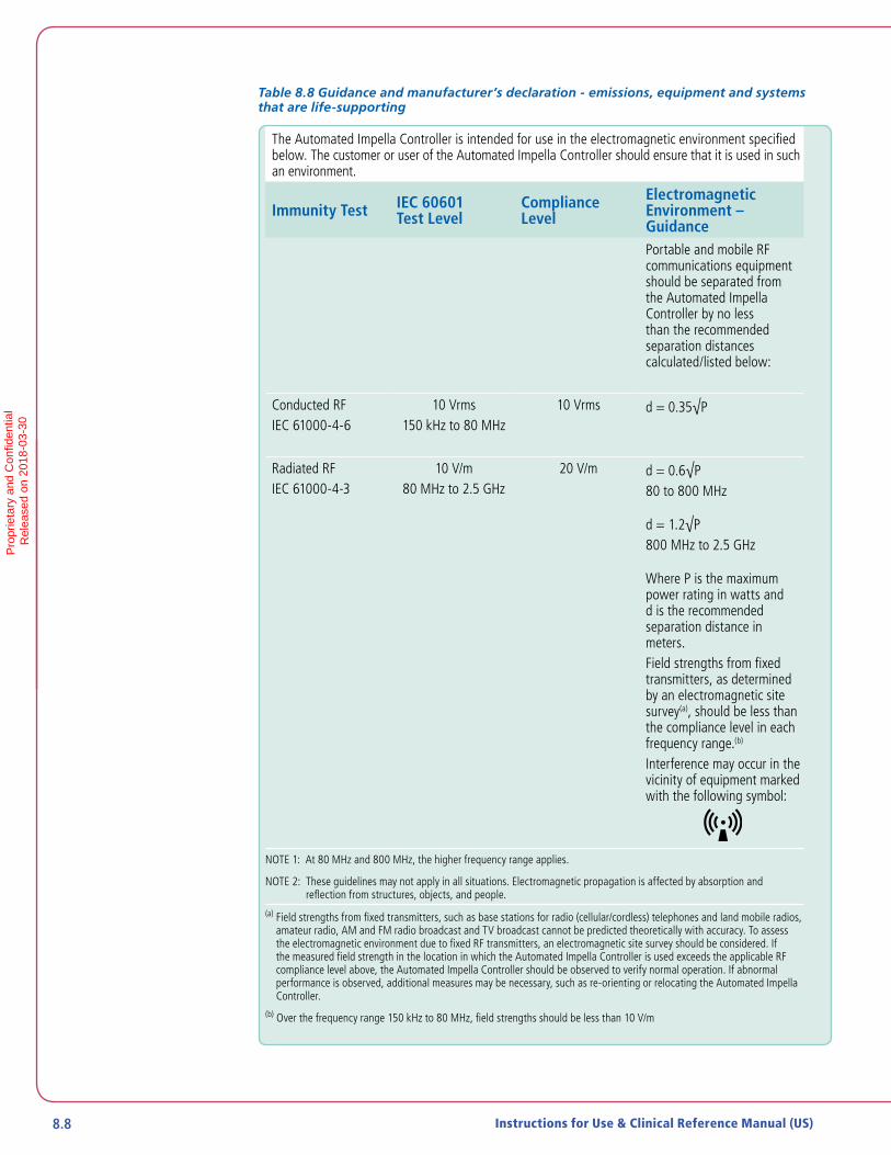
8.8 Instructions for Use & Clinical Reference Manual (US)
Table 8.8 Guidance and manufacturer’s declaration - emissions, equipment and systems that are life-supporting
The Automated Impella Controller is intended for use in the electromagnetic environment specified below. The customer or user of the Automated Impella Controller should ensure that it is used in such an environment.
Immunity Test IEC 60601 Test Level
Compliance Level
Electromagnetic Environment – GuidancePortable and mobile RF communications equipment should be separated from the Automated Impella Controller by no less than the recommended separation distances calculated/listed below:
Conducted RFIEC 61000-4-6
10 Vrms150 kHz to 80 MHz
10 Vrms d = 0.35√P
Radiated RFIEC 61000-4-3
10 V/m80 MHz to 2.5 GHz
20 V/m d = 0.6√P80 to 800 MHz
d = 1.2√P800 MHz to 2.5 GHz
Where P is the maximum power rating in watts and d is the recommended separation distance in meters.Field strengths from fixed transmitters, as determined by an electromagnetic site survey(a), should be less than the compliance level in each frequency range.(b)
Interference may occur in the vicinity of equipment marked with the following symbol:
NOTE 1: At 80 MHz and 800 MHz, the higher frequency range applies.
NOTE 2: These guidelines may not apply in all situations. Electromagnetic propagation is affected by absorption and reflection from structures, objects, and people.
(a) Field strengths from fixed transmitters, such as base stations for radio (cellular/cordless) telephones and land mobile radios, amateur radio, AM and FM radio broadcast and TV broadcast cannot be predicted theoretically with accuracy. To assess the electromagnetic environment due to fixed RF transmitters, an electromagnetic site survey should be considered. If the measured field strength in the location in which the Automated Impella Controller is used exceeds the applicable RF compliance level above, the Automated Impella Controller should be observed to verify normal operation. If abnormal performance is observed, additional measures may be necessary, such as re-orienting or relocating the Automated Impella Controller.
(b) Over the frequency range 150 kHz to 80 MHz, field strengths should be less than 10 V/m
Pro
prie
tary
and
Con
fiden
tial
R
elea
sed
on 2
018-
03-3
0
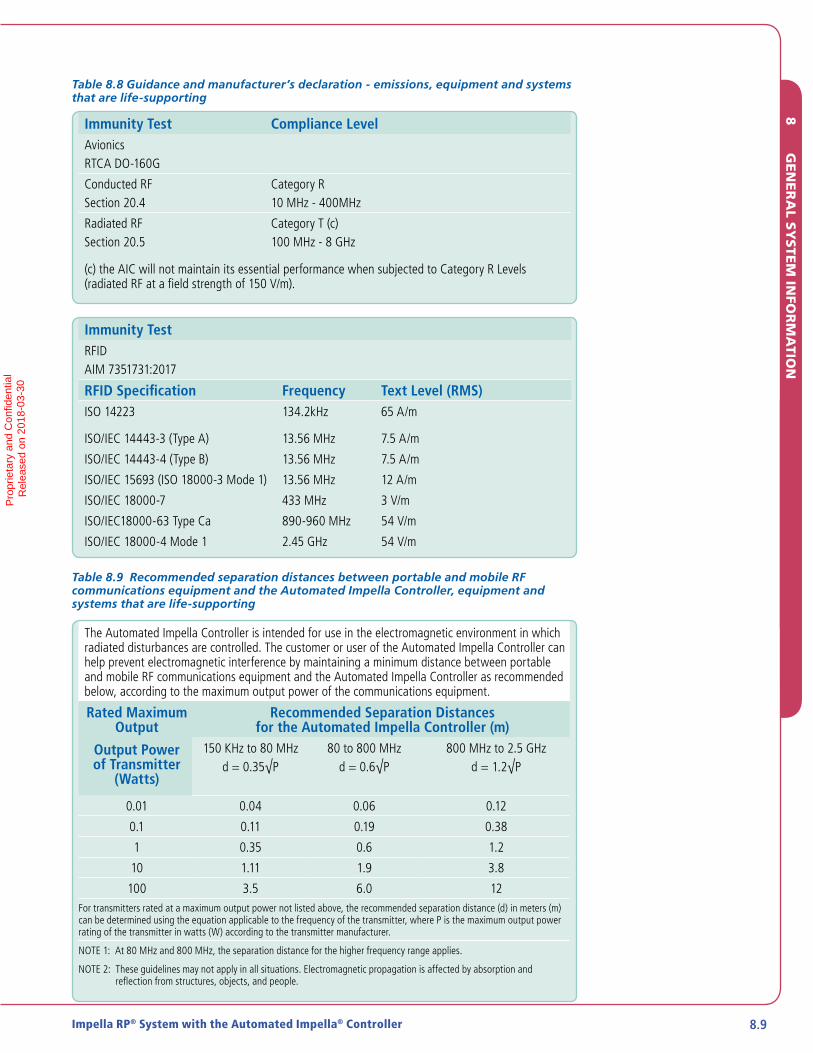
8.9Impella RP® System with the Automated Impella® Controller
Table 8.8 Guidance and manufacturer’s declaration - emissions, equipment and systems that are life-supporting
Immunity Test Compliance LevelAvionicsRTCA DO-160G
Conducted RFSection 20.4
Category R10 MHz - 400MHz
Radiated RFSection 20.5
Category T (c)100 MHz - 8 GHz
(c) the AIC will not maintain its essential performance when subjected to Category R Levels (radiated RF at a field strength of 150 V/m).
Immunity TestRFIDAIM 7351731:2017
RFID Specification Frequency Text Level (RMS)ISO 14223 134.2kHz 65 A/m
ISO/IEC 14443-3 (Type A) 13.56 MHz 7.5 A/m
ISO/IEC 14443-4 (Type B) 13.56 MHz 7.5 A/m
ISO/IEC 15693 (ISO 18000-3 Mode 1) 13.56 MHz 12 A/m
ISO/IEC 18000-7 433 MHz 3 V/m
ISO/IEC18000-63 Type Ca 890-960 MHz 54 V/m
ISO/IEC 18000-4 Mode 1 2.45 GHz 54 V/m
Table 8.9 Recommended separation distances between portable and mobile RF communications equipment and the Automated Impella Controller, equipment and systems that are life-supporting
The Automated Impella Controller is intended for use in the electromagnetic environment in which radiated disturbances are controlled. The customer or user of the Automated Impella Controller can help prevent electromagnetic interference by maintaining a minimum distance between portable and mobile RF communications equipment and the Automated Impella Controller as recommended below, according to the maximum output power of the communications equipment.
Rated Maximum Output
Output Power of Transmitter
(Watts)
Recommended Separation Distances for the Automated Impella Controller (m)
150 KHz to 80 MHzd = 0.35√P
80 to 800 MHzd = 0.6√P
800 MHz to 2.5 GHzd = 1.2√P
0.01 0.04 0.06 0.12
0.1 0.11 0.19 0.38
1 0.35 0.6 1.2
10 1.11 1.9 3.8
100 3.5 6.0 12For transmitters rated at a maximum output power not listed above, the recommended separation distance (d) in meters (m) can be determined using the equation applicable to the frequency of the transmitter, where P is the maximum output power rating of the transmitter in watts (W) according to the transmitter manufacturer.
NOTE 1: At 80 MHz and 800 MHz, the separation distance for the higher frequency range applies.
NOTE 2: These guidelines may not apply in all situations. Electromagnetic propagation is affected by absorption and reflection from structures, objects, and people.
8
GE
NE
RA
L SY
STE
M IN
FOR
MA
TION
Pro
prie
tary
and
Con
fiden
tial
R
elea
sed
on 2
018-
03-3
0

8.10 Instructions for Use & Clinical Reference Manual (US)
Table 8.10 RFID transmitter / receiver specifications
RFID Transmitter / Receiver SpecificationsFrequency 13.56 MHz
Receiver bandwidth 14 kHz
Effective radiated power 30 nW
Modulation ASK
Table 8.11 Impella Connect Wi-Fi transmitter / reveiver specifications
IEEE Protocols 802.11a, 802.11b, 802.11g, and 802.11n
Receiver bandwidth 120 MHz/ 40 MHz
Effective radiated power <0.071 watts
Frequency Bands 2412 MHz to 2462 MHz US 2412 MHz to 2472 MHz EU 2412 MHz to 2684 MHz JP5180 MHz to 5825 MHz US 5180 MHz to 5700 MHz EU 5180 MHz to 5700 MHz JP
IEEE 802.11a 802.11b 802.11g 802.11n
Modulation OFDM D5.55 OFDM MxMO OFMD
Video Frame Rate 20 fps (Maximum)
Data Rate 512 Kbps (Average)
Certified Wi-Fi Module
Manufacturer: Texas Instruments
Part number: WL18MODGI
FCC ID: Z64-WL18DBMOD
Pro
prie
tary
and
Con
fiden
tial
R
elea
sed
on 2
018-
03-3
0
8.11Impella RP® System with the Automated Impella® Controller
TRANSPORT BETWEEN HOSPITALS
The Automated Impella Controller (AIC) performs as intended when exposed to radiofrequency (RF) disturbances below 20 V/m. During transport, the AIC may be exposed to RF disturbances above 20 V/m, which could cause minor problems, such as intermittent displays of soft button menu selections, which have no effect on the operating paramaters of the Impella support system, and will resolve readily once the disturbance ends. It could also potentially result in loss of support. Patients must be closely monitored at all times during transport.
Do not transport an Impella patient via commerical aircraft. Loss of support may occur aboard a commercial aircraft due to exposure to radiofrequency (RF) disturbances above the compliance level (<20 V/m) of the Automated Impella Controller.
GUIDELINES FOR PATIENT TRANSPORT
Intra-hospital transport may be required if a patient requires additional resources and specialized teams located at another hospital. The patient may be transferred to such a location using the Automated Impella Controller for hospital-to-hospital transport via ambulance, or helicopter, or fixed-wing aircraft specially outfitted and equipped for transport of critically ill patients. Do not transport the patient via commercial aircraft. Loss of support may occur aboard a commercial aircraft due to exposure to extreme radiofrequency (RF) disturbances.
Patients must be closely monitored at all times during transport. Maintaining optimal patient hemodynamic status and correct Impella Catheter position are two key factors in managing patients supported with the Impella Ventricular Support Systems during transport. Steps should be taken to eliminate or minimize any aspect of the transport that might adversely affect these factors.
The Automated Impella Controller is designed to operate for 60 minutes on battery power. Transport teams should take this into consideration when planning the transport. If the total transport time is expected to include more than 60 minutes during which the system will be disconnected from AC power, arrangements should be made to use a vehicle with a built-in DC to AC power inverter.
IMPORTANT TRANSPORT CONSIDERATIONS
1. Planning is critical to success. Abiomed representatives can help with planning for transport. They can be contacted 24 hours a day at 1-800-422-8666.
2. The Automated Impella Controller should be fully charged prior to transport. Keep the Automated Impella Controller connected to AC power (or an AC inverter) whenever possible.
3. Do not stress the connector cable from the controller to the Impella Catheter. Such tension could move the catheter out of correct position and compromise patient circulatory support.
4. Carefully monitor purge pressures during changes in altitude.
5. The Automated Impella Controller should be positioned to allow easy access to the display screen and soft buttons to view alarms and make any necessary changes.
6. Maintain ACTs between 160 and 180 or at the level recommended by the physician responsible for the patient.
8
GE
NE
RA
L SY
STE
M IN
FOR
MA
TION
Pro
prie
tary
and
Con
fiden
tial
R
elea
sed
on 2
018-
03-3
0

8.12 Instructions for Use & Clinical Reference Manual (US)
FAA ADVISORY
The Automated Impella Controller has been subjected to, and passed, the EMC/EMI tests as specified in IEC 60601-1-2 (General requirements for safety—Collateral standard: Electromagnetic compatibility—Requirements and tests). The Automated Impella Controller does not, however, meet the requirements for conducted emissions of RTCA/DO-160G section 21.4 and has not been tested for radiated emissions per RTCA/DO-160G section 21.5. Abiomed recommends that air transport carriers follow the guidance FAA Advisory Circular AC No: 91-21.1B. Section 8-a of FAA Advisory Circular AC No: 91-21.1B states:
“Equipment tested and found to exceed the section 21, Category M, emission levels are required to be evaluated in the operator’s M-PED selected model aircraft for electromagnetic interference (EMI) and radio frequency interference (RFI). All navigation, communication, engine, and flight control systems will be operating in the selected aircraft during the evaluation.”
TRANSPORT WITHIN THE HOSPITAL
Patients supported with the Impella System may require transport within the hospital.
Considerations for transport within the hospital:
• The Automated Impella Controller and Impella Catheter are designed to operate on battery power for at least 1 hour.
• Confirm that the battery capacity displayed on the controller is 100%.
• If transport time might be longer than 1 hour, bring an extension cord or confirm that you will be able to connect the controller to AC power once you arrive at your destination.
• When rolling the Automated Impella Controller cart across a threshold, firmly grasp the cart handle and pull it over the threshold.
• Pay close attention to all system components and connections when rolling the Automated Impella Controller cart over thresholds and through elevator doors.
• Do not stress the connector cable from the controller to the Impella Catheter.
Pro
prie
tary
and
Con
fiden
tial
R
elea
sed
on 2
018-
03-3
0
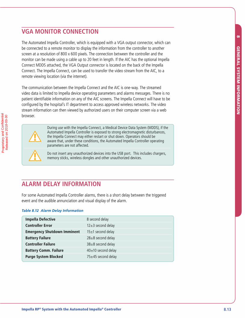
8.13Impella RP® System with the Automated Impella® Controller
VGA MONITOR CONNECTION
The Automated Impella Controller, which is equipped with a VGA output connector, which can be connected to a remote monitor to display the information from the controller to another screen at a resolution of 800 x 600 pixels. The connection between the controller and the monitor can be made using a cable up to 20 feet in length. If the AIC has the optional Impella Connect MDDS attached, the VGA Output connector is located on the back of the Impella Connect. The Impella Connect, can be used to transfer the video stream from the AIC, to a remote viewing location (via the internet).
The communication between the Impella Connect and the AIC is one-way. The streamed video data is limited to Impella device operating parameters and alarms messages. There is no patient identifiable information on any of the AIC screens. The Impella Connect will have to be configured by the hospital’s IT department to access approved wireless networks. The video stream information can then viewed by authorized users on their computer screen via a web browser.
During use with the Impella Connect, a Medical Device Data System (MDDS), if the Automated Impella Controller is exposed to strong electromagnetic disturbances, the Impella Connect may either restart or shut down. Operators should be aware that, under these conditions, the Automated Impella Controller operating parameters are not affected.
Do not insert any unauthorized devices into the USB port. This includes chargers, memory sticks, wireless dongles and other unauthorized devices.
ALARM DELAY INFORMATION
For some Automated Impella Controller alarms, there is a short delay between the triggered event and the audible annunciation and visual display of the alarm.
Table 8.12 Alarm Delay Information
Impella Defective 8 second delay
Controller Error 12±3 second delay
Emergency Shutdown Imminent 15±1 second delay
Battery Failure 28±8 second delay
Controller Failure 38±8 second delay
Battery Comm. Failure 40±10 second delay
Purge System Blocked 75±45 second delay
8
GE
NE
RA
L SY
STE
M IN
FOR
MA
TION
Pro
prie
tary
and
Con
fiden
tial
R
elea
sed
on 2
018-
03-3
0

8.14 Instructions for Use & Clinical Reference Manual (US)
PATIENT ENVIRONMENT
The Automated Impella Controller and the components of the Impella RP System are approved for use within the patient environment defined in IEC 60601-1: 3rd edition and in the figure below.
2.5 m
CONTROLLER
1.5 m
1.5 m
CONTROLLER
Figure 8.1 Automated Impella Controller Patient Environment
USE ENVIRONMENT
The Automated Impella Controller system is suitable for use in hospital and transport environments. For additional detail, please refer to section 2.1 and section 8 .
WHITE CONNECTOR CABLE
Length 2.5 m
Service life Single use only
Pro
prie
tary
and
Con
fiden
tial
R
elea
sed
on 2
018-
03-3
0
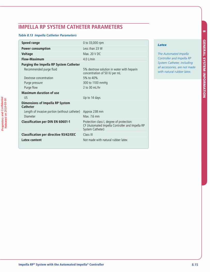
8.15Impella RP® System with the Automated Impella® Controller
IMPELLA RP SYSTEM CATHETER PARAMETERSTable 8.13 Impella Catheter Parameters
Speed range 0 to 33,000 rpm
Power consumption Less than 23 W
Voltage Max. 20 V DC
Flow-Maximum 4.0 L/min
Purging the Impella RP System CatheterRecommended purge fluid
Dextrose concentrationPurge pressurePurge flow
5% dextrose solution in water with heparin concentration of 50 IU per mL5% to 40%300 to 1100 mmHg2 to 30 mL/hr
Maximum duration of useUS Up to 14 days
Dimensions of Impella RP System Catheter
Length of invasive portion (without catheter)Diameter
Approx 238 mmMax. 7.6 mm
Classification per DIN EN 60601-1 Protection class I, degree of protection: CF (Automated Impella Controller and Impella RP System Catheter)
Classification per directive 93/42/EEC Class III
Latex content Not made with natural rubber latex
Latex
The Automated Impella Controller and Impella RP System Catheter, including all accessories, are not made with natural rubber latex.
8
GE
NE
RA
L SY
STE
M IN
FOR
MA
TION
Pro
prie
tary
and
Con
fiden
tial
R
elea
sed
on 2
018-
03-3
0
8.16 Instructions for Use & Clinical Reference Manual (US)
CLEANING
• Clean the Automated Impella Controller keypad and display with either 70% isopropyl alcohol or soap and water. (NOTE: Be aware that soft buttons may be activated when you spray or wipe the display.)
• Clean the Automated Impella Controller housing with mild detergent.
• Do not allow any fluids to enter the connector sockets.
• Clean the connector cable with 70% isopropyl alcohol.
STORING THE AUTOMATED IMPELLA CONTROLLER
The Li-Ion batteries must be charged for 5 hours prior to system operation in order to meet the runtime requirement of 1 hour. Failure to do so will yield a shorter runtime. After being unplugged, the Automated Impella Controller will operate for at least 60 minutes after the batteries have been fully charged.
• Place the Automated Impella Controller on a horizontal surface to prevent falling.
• Connect the AC power cord to an AC outlet.
• The battery may be destroyed if the Automated Impella Controller is stored with a depleted battery.
RETURNING AN IMPELLA RP SYSTEM CATHETER TO ABIOMED (UNITED STATES)
To return an Impella RP System Catheter to Abiomed, contact your local Clinical Consultant for an Abiomed-approved return kit.* The kit includes instructions for returning the Impella RP System Catheter to Abiomed.
* Only available in the United States
Alcohol Warning
Do NOT clean the Impella Catheter infusion filter or pressure reservoir with alcohol and AVOID exposing these components to products containing alcohol.
Storing the Controller
To keep the Automated Impella Controller battery charged, the controller should be plugged into an AC outlet. When plugged into an AC outlet, the controller battery will charge whether the controller is on or off.
Pro
prie
tary
and
Con
fiden
tial
R
elea
sed
on 2
018-
03-3
0

APPENDIX A: AUTOMATED IMPELLA® CONTROLLER MENU STRUCTURE .. A.1
Overview .........................................................................................................A.1
Mute Alarm .....................................................................................................A.1
Flow Control ....................................................................................................A.1
Display ........................................................................................................... A.2
Purge Menu .................................................................................................... A.2
Menu ............................................................................................................. A.3
APPENDICES
Pro
prie
tary
and
Con
fiden
tial
R
elea
sed
on 2
018-
03-3
0

Pro
prie
tary
and
Con
fiden
tial
R
elea
sed
on 2
018-
03-3
0

A.1Impella RP® System with the Automated Impella® Controller A.1
APPENDIX A: AUTOMATED IMPELLA® CONTROLLER MENU STRUCTURE
OVERVIEW
The soft buttons on the Automated Impella Controller provide access to the controller menu structure. The menu structure has 6 main elements:
• MUTE ALARM
• FLOW CONTROL
• DISPLAY
• PURGE MENU
• MENU
This Appendix provides an overview of the Automated Impella Controller menu structure. Many of the functions accessed through this menu structure are also discussed elsewhere in this manual.
MUTE ALARM
The MUTE ALARM soft button mutes (silences) active alarms. It does not open another menu.
When you press MUTE ALARM, a bell icon with an X through it replaces the words "MUTE ALARM" in the upper right of the display screen. If no alarms are active, no bell icon is displayed. When you press MUTE ALARM it acknowledges all active alarms and silences the audible alarm indicator for 2 minutes (for red or yellow alarms) or 5 minutes (for white alarms). (Refer to section 7 of this manual for more information about Automated Impella Controller Alarms.)
FLOW CONTROL
The FLOW CONTROL soft button opens the performance level icon enabling you to select the desired performance level. The procedure for setting performance level is described in “Positioning and Starting the Impella RP System Catheter” in section 5.
AP
PE
ND
IX C
AP
PE
ND
IX C
AP
PE
ND
IX A
Pro
prie
tary
and
Con
fiden
tial
R
elea
sed
on 2
018-
03-3
0

A.2 Instructions for Use & Clinical Reference Manual (US)
DISPLAY
The DISPLAY soft button opens a menu that includes the following options for viewing waveforms and navigating to other screen displays:
• Y-axis Scale—opens a menu from which you can select a waveform and change its appearance by adjusting the scale of the y-axis.
Once the waveform is selected, turn the selector knob clockwise to increase the y-axis scale and counterclockwise to decrease the y-axis scale.
Select OK to accept the new y-axis scale.
Select Restore to return to the default y-axis scale.
Select Initial to set the y-axis to the previously set scale.
Select Center Signal to center the waveform.
Select Cancel to exit the tool.
• Time Scale—allows you to apply different time scales to the currently displayed waveforms.
• Center—automatically centers the motor current waveform and adjusts the range accordingly.
• Infusion—opens the infusion history screen. The infusion history screen, which is discussed in section 4 of this manual, shows the volume and the amount of heparin and dextrose delivered. The top entry in the table shows the volume and amount of heparin and dextrose infused from the top of the hour through the current time.
• Purge—displays the purge system waveforms and pressure and flow values.
• Placement—opens the placement signal / motor current screen (described in section 4 under “Placement Screen”).
• Display Speed Pulse— allows you to see the speed pulses in the motor current.
PURGE MENU
The PURGE MENU soft button opens a menu that includes the following purge system procedure options:
• Change Purge Fluid Bag—starts the procedure to change the purge fluid
• Change Cassette and Bag—starts the procedure to change both the purge fluid and purge cassette
• De-Air Purge System—starts the de-air procedure
These procedures are described in section 5 of this manual.
Pro
prie
tary
and
Con
fiden
tial
R
elea
sed
on 2
018-
03-3
0
A.3Impella RP® System with the Automated Impella® Controller A.3
MENU
The MENU soft button opens a menu of options related to controller settings, alarm history, repositioning, offset adjustment, and starting a procedure. The menu includes the following options:
• Settings / ServiceService
System Information. Opens the System Information table. This provides information about the software version, IP addresses, current type of Impella Catheter, and current catheter runtime.
Set Date/Time. Displays the menu for changing the date and time
USB Data Download. When no pump is connected, this display appears for downloading data logs to a USB device
Service Timers. Displays the Service Timers menu. Console operating time and purge motor operating time are displayed in hours.
Screen Brightness. Opens the Screen Brightness selection box. The brightness of the screen display can be set from 50% to 100%. Select OK to confirm selection. Select Cancel to cancel selection.
Language. When the software supports multi-language, this opens the Language selection box. Opens the Language selection box. Use the selector knob to select German, English, French, Italian, Spanish, or Dutch. The system will immediately change the language on the controller for all displayed text. This language will be used after system restart unless another language is selected.
Disable (Enable) Retrograde Flow Control.
Disable (Enable) Audio – Placement Signal not Reliable. Allows you to enable or disable audio for the Impella Placement Signal not Reliable alarm. This selection is available only if an Impella Placement Signal not Reliable alarm is active or the audio has been disabled for this alarm.
Disable (Enable) Audio – Purge Pressure High / System Blocked. Allows you to enable or disable audio for the Purge Pressure High or Purge System Blocked alarms. This selection is only available if one of these two alarms is active or the audio has been disabled for one of these alarms.
Disable (Enable) Audio - Suction. Allows you to enable or disable audio for Suction alarms. This selection is available only if a Suction alarm is active or the audio has been disabled for this alarm.
Enable (Disable) Purge Flow Change Notifications. Allows you to enable or disable the purge flow notification white alarms ("Purge Flow Increased" and "Purge Flow Decreased").
Enable (Disable) Surgical Mode. Allows you to enable or disable Surgical Mode. If Surgical Mode is enabled, the "Impella Stopped" alarm is silenced at P-0.
AP
PE
ND
IX C
AP
PE
ND
IX A
Pro
prie
tary
and
Con
fiden
tial
R
elea
sed
on 2
018-
03-3
0

A.4 Instructions for Use & Clinical Reference Manual (US)
• Alarm History—opens the Alarm History table. This provides a visual display of the chronology of stored alarm messages. The most recently occurring alarm message is displayed at the top of the list. For each message, the date and time it occurred and the alarm message heading is displayed. You can use the selector knob to select individual alarm messages and an explanation for the selected alarm message will be displayed in the failure description box. Press EXIT to exit the alarm history analysis.
• Start Data Snapshot—starts the timed data recording function to save real-time operating data for later analysis.
• Start Manual Zero—opens the procedure for manually zeroing the differential pressure sensor.
• Case Start—begins the case procedure. Case Start is described in section 5 of this manual under “Case Start.”
Pro
prie
tary
and
Con
fiden
tial
R
elea
sed
on 2
018-
03-3
0

INDEXIndex
AAbbreviations, 8.1Adverse events (potential), 1.1Alarms
Advisory (white) alarmsDescription, 7.1Messages, actions, and causes, 7.3
Alarm delay information, 8.12Alarm display, 7.2Alarm history screen, 7.2, A.4Alarm levels, Alarm messages, 7.3Alarm window, 4.5
(figure), 7.2Critical (red) alarms
Description, 7.1Messages, actions, and causes, 7.3
Handling alarms, 7.3High purge pressure, 5.18Low purge pressure, 5.17Mute alarm function, 7.2Mute alarm indicator, 4.6
(figure), 7.2Overview, Serious (yellow) alarms
Description, 7.1Messages, actions, and causes, 7.3
Anchoring ring (See Catheter: Catheter components: Repositioning unit)
Anticontamination sleeve (See Catheter: Catheter components: Repositioning unit)
Automated Impella Controller (See Controller)
BBattery switch, 4.1
CCatheter
Catheter componentsBlue Impella plug, 3.4
(figure), 3.3Memory, 3.4
Cannula, 3.3(figure), 3.3
Catheter shaft, 3.4(figure), 3.3
Check valve, 3.4(figure), 3.3
Clear sidearm, 3.4(figure), 3.3
Differential pressure sensor, 3.3(figure), 3.3
Infusion filter, 3.4(figure), 3.3
Inlet area, 3.4(figure), 3.3
Motor housing, 3.4, 8.1(figure), 3.3
Outlet area, 3.3(figure), 3.3
Pigtail, 3.3(figure), 3.3
Pressure reservoir, 3.4(figure), 3.3
Repositioning unit, 3.4(figure), 3.3
Catheter shaft
Differential pressure measurement cable, 3.4Electrical cable, 3.4Purge lumen, 3.4
Description, 3.3(figure), 3.3
Differential pressure sensor, 3.4Parameters, 8.13Returning an Impella 5.0 Catheter to Abiomed
(US), 8.14Using the catheter
Inserting the catheter, 5.10Positioning and starting the catheter, 5.11
(figure), 5.12Preparing the catheter, 5.10
(figure), 5.6Catheter operation icon, 4.7Catheter serial number
Definition, 4.5(figure), 4.5
Cautions, 2.3Connector cable
Connecting the connector cable, 5.6(figure), 5.6
Description, 3.8(figure), 3.8
Specifications, 8.13Contraindications, 1.1Controller
AC fuses, 4.4(figure), 4.3
AC plug, 4.4(figure), 4.3
Alarm history screen, 7.2Alarms, Battery power, 3.5, 4.11Battery switch, 4.1Bed mount, 4.4
(figure), 4.3Catheter plug, 4.2
(figure), 4.1Description, 3.5, 4.1
(figure), 3.2, 3.5, 4.1, 4.3Display options, 4.2Display screen
Alarm window, 4.5Catheter serial number, 4.5Central display area, 4.7Description, 4.2
(figure), 4.1, 4.3Flow area, 4.7Mute alarm indicator, 4.6Purge system area, 4.7Soft buttons, 4.6System date and time, 4.5System power area, 4.6
Equipotential ground stud, 4.4(figure), 4.3
Ethernet jack, 4.4(figure), 4.3
Home screen(figure), 4.5
Infusion history screenDescription, 4.10(figure), 4.11
Menu structure overview, A.1Mobile operation, 4.11
Motor current screen, 4.9(figure), 4.8
Placement screenDescription, 4.8(figure), 4.8Motor current waveform, 4.9
(figure), 4.8Placement signal waveform, 4.8
(figure), 4.8Placement signal screen
Confirming placement of Impella 5.0 Catheter(figure), 5.12
Power indicator, 4.2(figure), 4.1
Power switch, 4.4(figure), 4.3
Purge cassette door, 4.2(figure), 4.1
Purge cassette release button, 4.4(figure), 4.3
Purge screenDescription, 4.9(figure), 4.9Purge flow, 4.10Purge pressure, 4.10
RS-232 service jack(figure), 4.3
Selector knob, 4.2(figure), 4.1
Slave monitor connection, 4.2Soft buttons
Description, 4.2, 4.6(figure), 4.1, 4.5
DISPLAY, Center, A.2Infusion, A.2Placement, A.2Purge, A.2Time scale, A.2Y-axis scale, A.2
MENU, Alarm history, A.4Case start, A.4Disable/Enable Audio-Impella Sensor Failure,
A.3Disable/Enable Audio-Purge Flow Low/
System Blocked, A.3Disable/Enable placement monitoring, A.3Disable/Enable reverse flow control, A.3Language, A.3Screen brightness, A.3Service timers, A.3Set date/time, A.3Settings/Service, A.3Start offset adjustment, A.4System information, A.3Timed data recording, A.4
MUTE ALARM, 4.6P-LEVEL, PURGE SYSTEM,
Change purge fluid, A.2Change purge system, A.2De-air purge system, A.2
SpecificationsElectrical, 8.3Electromagnetic compatibility, 8.6
RFID transmitter / Receiver specifications, 8.9
Pro
prie
tary
and
Con
fiden
tial
R
elea
sed
on 2
018-
03-3
0
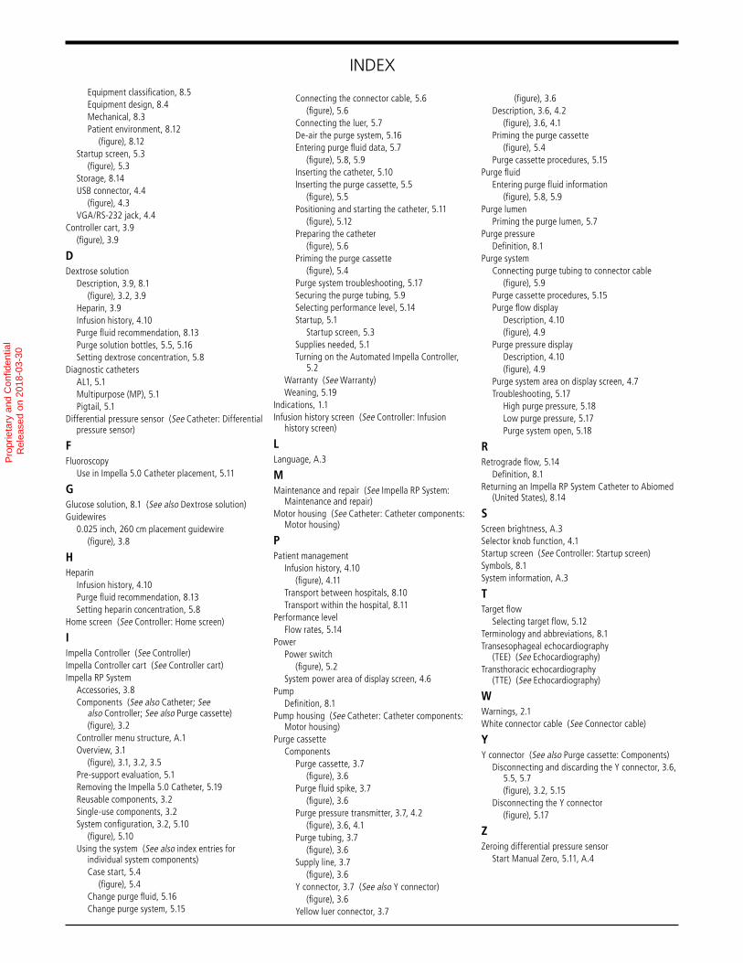
INDEXEquipment classification, 8.5Equipment design, 8.4Mechanical, 8.3Patient environment, 8.12
(figure), 8.12Startup screen, 5.3
(figure), 5.3Storage, 8.14USB connector, 4.4
(figure), 4.3VGA/RS-232 jack, 4.4
Controller cart, 3.9(figure), 3.9
DDextrose solution
Description, 3.9, 8.1(figure), 3.2, 3.9
Heparin, 3.9Infusion history, 4.10Purge fluid recommendation, 8.13Purge solution bottles, 5.5, 5.16Setting dextrose concentration, 5.8
Diagnostic cathetersAL1, 5.1Multipurpose (MP), 5.1Pigtail, 5.1
Differential pressure sensor (See Catheter: Differential pressure sensor)
FFluoroscopy
Use in Impella 5.0 Catheter placement, 5.11
GGlucose solution, 8.1 (See also Dextrose solution)Guidewires
0.025 inch, 260 cm placement guidewire(figure), 3.8
HHeparin
Infusion history, 4.10Purge fluid recommendation, 8.13Setting heparin concentration, 5.8
Home screen (See Controller: Home screen)
IImpella Controller (See Controller)Impella Controller cart (See Controller cart)Impella RP System
Accessories, 3.8Components (See also Catheter; See
also Controller; See also Purge cassette)(figure), 3.2
Controller menu structure, A.1Overview, 3.1
(figure), 3.1, 3.2, 3.5Pre-support evaluation, 5.1Removing the Impella 5.0 Catheter, 5.19Reusable components, 3.2Single-use components, 3.2System configuration, 3.2, 5.10
(figure), 5.10Using the system (See also index entries for
individual system components)Case start, 5.4
(figure), 5.4Change purge fluid, 5.16Change purge system, 5.15
Connecting the connector cable, 5.6(figure), 5.6
Connecting the luer, 5.7De-air the purge system, 5.16Entering purge fluid data, 5.7
(figure), 5.8, 5.9Inserting the catheter, 5.10Inserting the purge cassette, 5.5
(figure), 5.5Positioning and starting the catheter, 5.11
(figure), 5.12Preparing the catheter
(figure), 5.6Priming the purge cassette
(figure), 5.4Purge system troubleshooting, 5.17Securing the purge tubing, 5.9Selecting performance level, 5.14Startup, 5.1
Startup screen, 5.3Supplies needed, 5.1Turning on the Automated Impella Controller,
5.2Warranty (See Warranty)Weaning, 5.19
Indications, 1.1Infusion history screen (See Controller: Infusion
history screen)
LLanguage, A.3
MMaintenance and repair (See Impella RP System:
Maintenance and repair)Motor housing (See Catheter: Catheter components:
Motor housing)
PPatient management
Infusion history, 4.10(figure), 4.11
Transport between hospitals, 8.10Transport within the hospital, 8.11
Performance levelFlow rates, 5.14
PowerPower switch
(figure), 5.2System power area of display screen, 4.6
PumpDefinition, 8.1
Pump housing (See Catheter: Catheter components: Motor housing)
Purge cassetteComponents
Purge cassette, 3.7(figure), 3.6
Purge fluid spike, 3.7(figure), 3.6
Purge pressure transmitter, 3.7, 4.2(figure), 3.6, 4.1
Purge tubing, 3.7(figure), 3.6
Supply line, 3.7(figure), 3.6
Y connector, 3.7 (See also Y connector)(figure), 3.6
Yellow luer connector, 3.7
(figure), 3.6Description, 3.6, 4.2
(figure), 3.6, 4.1Priming the purge cassette
(figure), 5.4Purge cassette procedures, 5.15
Purge fluidEntering purge fluid information
(figure), 5.8, 5.9Purge lumen
Priming the purge lumen, 5.7Purge pressure
Definition, 8.1Purge system
Connecting purge tubing to connector cable(figure), 5.9
Purge cassette procedures, 5.15Purge flow display
Description, 4.10(figure), 4.9
Purge pressure displayDescription, 4.10(figure), 4.9
Purge system area on display screen, 4.7Troubleshooting, 5.17
High purge pressure, 5.18Low purge pressure, 5.17Purge system open, 5.18
RRetrograde flow, 5.14
Definition, 8.1Returning an Impella RP System Catheter to Abiomed
(United States), 8.14
SScreen brightness, A.3Selector knob function, 4.1Startup screen (See Controller: Startup screen)Symbols, 8.1System information, A.3
TTarget flow
Selecting target flow, 5.12Terminology and abbreviations, 8.1Transesophageal echocardiography
(TEE) (See Echocardiography)Transthoracic echocardiography
(TTE) (See Echocardiography)
WWarnings, 2.1White connector cable (See Connector cable)
YY connector (See also Purge cassette: Components)
Disconnecting and discarding the Y connector, 3.6, 5.5, 5.7(figure), 3.2, 5.15
Disconnecting the Y connector(figure), 5.17
ZZeroing differential pressure sensor
Start Manual Zero, 5.11, A.4
Pro
prie
tary
and
Con
fiden
tial
R
elea
sed
on 2
018-
03-3
0

INDEX
Pro
prie
tary
and
Con
fiden
tial
R
elea
sed
on 2
018-
03-3
0

Pro
prie
tary
and
Con
fiden
tial
R
elea
sed
on 2
018-
03-3
0

Pro
prie
tary
and
Con
fiden
tial
R
elea
sed
on 2
018-
03-3
0

Abiomed, Inc.22 Cherry Hill DriveDanvers, Massachusetts 01923 USAVoice: 978-777-5410Facsimile: 978-777-8411Email: [email protected]
Abiomed Europe GmbHNeuenhofer Weg 352074 Aachen, GermanyVoice: +49 (241) 8860-0Facsimile: +49 (241) 8860-111Email: [email protected]
Clinical support 24 hours per day, 7 days a week:
1-800-422-8666 (US)
+49 (0) 1805 2246633 (EU)
www.abiomed.com
Pro
prie
tary
and
Con
fiden
tial
R
elea
sed
on 2
018-
03-3
0