CIRCULARLY POLARIZED SPIDRON FRACTAL SLOT ANTENNA … · slot antenna array developed for broadband...
16
Progress In Electromagnetics Research, Vol. 137, 203–218, 2013 CIRCULARLY POLARIZED SPIDRON FRACTAL SLOT ANTENNA ARRAYS FOR BROADBAND SATELLITE COMMUNICATIONS IN KU-BAND Son Trinh-Van, Han Byul Kim, Gina Kwon, and Keum Cheol Hwang * Division of Electronics and Electrical Engineering, Dongguk University-Seoul, 26, Pil-dong 3-ga, Chung-gu, Seoul 100-715, South Korea Abstract—In this paper, a novel circularly polarized Spidron fractal slot antenna array developed for broadband satellite communication in the Ku-band is discussed. A Spidron fractal slot configuration was utilized as a single radiating element to achieve circularly polarized radiation. The effects of altering the feeding position on the resonance behavior and the radiative characteristics were assessed. As a consequence, the design was expanded from a single element to a 2×2 subarray and further to a 4×4 array in order to enhance the bandwidth performance of the antenna when integrated with a sequential feeding network. Two prototype arrays were fabricated and tested, and measurements revealed that the 2×2 subarray has a 10-dB reflection coefficient bandwidth between 10 and 14.28 GHz, 3 dB axial ratio bands between 10.15 and 11.15 GHz and between 11.75 and 13.92 GHz, and a maximum gain of 11.4 dB at 13 GHz. The results for the 4×4 array indicated that both the 10-dB reflection coefficient and 3 dB axial ratio bandwidths cover the entire operating frequency from 10 to 15 GHz in the Ku-band. The maximum gain for the 4×4 array was 15.63 dB at 12.6 GHz. 1. INTRODUCTION Owing to their low profile, light weight, and the ease with which they can be integrated with active devices, microstrip antennas have become widely used over the past few decades [1–8]. Recently, circularly polarized (CP) microstrip antennas, in particular, have been attracting Received 4 January 2013, Accepted 12 February 2013, Scheduled 18 February 2013 * Corresponding author: Keum Cheol Hwang ([email protected]).
Transcript of CIRCULARLY POLARIZED SPIDRON FRACTAL SLOT ANTENNA … · slot antenna array developed for broadband...
Progress In Electromagnetics Research, Vol. 137, 203–218, 2013
CIRCULARLY POLARIZED SPIDRON FRACTAL SLOTANTENNA ARRAYS FOR BROADBAND SATELLITECOMMUNICATIONS IN KU-BAND
Son Trinh-Van, Han Byul Kim, Gina Kwon,and Keum Cheol Hwang*
Division of Electronics and Electrical Engineering, DonggukUniversity-Seoul, 26, Pil-dong 3-ga, Chung-gu, Seoul 100-715, SouthKorea
Abstract—In this paper, a novel circularly polarized Spidron fractalslot antenna array developed for broadband satellite communicationin the Ku-band is discussed. A Spidron fractal slot configuration wasutilized as a single radiating element to achieve circularly polarizedradiation. The effects of altering the feeding position on the resonancebehavior and the radiative characteristics were assessed. As aconsequence, the design was expanded from a single element to a 2×2subarray and further to a 4×4 array in order to enhance the bandwidthperformance of the antenna when integrated with a sequential feedingnetwork. Two prototype arrays were fabricated and tested, andmeasurements revealed that the 2×2 subarray has a 10-dB reflectioncoefficient bandwidth between 10 and 14.28 GHz, 3 dB axial ratio bandsbetween 10.15 and 11.15 GHz and between 11.75 and 13.92GHz, anda maximum gain of 11.4 dB at 13 GHz. The results for the 4×4 arrayindicated that both the 10-dB reflection coefficient and 3 dB axial ratiobandwidths cover the entire operating frequency from 10 to 15 GHz inthe Ku-band. The maximum gain for the 4×4 array was 15.63 dB at12.6GHz.
1. INTRODUCTION
Owing to their low profile, light weight, and the ease with which theycan be integrated with active devices, microstrip antennas have becomewidely used over the past few decades [1–8]. Recently, circularlypolarized (CP) microstrip antennas, in particular, have been attracting
Received 4 January 2013, Accepted 12 February 2013, Scheduled 18 February 2013* Corresponding author: Keum Cheol Hwang ([email protected]).

204 Trinh-Van, Kim, Kwon, and Hwang
considerable attention for their usefulness in many applications suchas for satellite communications [9] and in radio frequency identification(RFID) readers [10, 11]. Microstrip-fed CP antennas may be classifiedas either single-feed or dual-feed, based on the number of feedersthey employ; single-feed antennas are preferred, as they eliminatethe need for 90 hybrid couplers. Several designs for single-feedCP antennas have been described, such as a Koch fractal boundaryCP microstrip antenna [12], a compact CP patch antenna loadedwith a metamaterial [13], and a shorted CP patch antenna using ahigh-permittivity substrate [14]. However, all of the single-feed CPantennas described above usually have the disadvantage of featuringa very narrow 3 dB axial ratio (AR) bandwidth (typically 1–4%).To increase the bandwidth performance, square-slot antennas withmultiple monopole elements [15] or a halberd-shaped feeder [16] wereproposed; these allow for 3 dB AR bandwidths of 28.03% and 29.1%,respectively. A technique based on a chiral metamaterial structurewas also applied to enhance the performance of the CP antenna [17].In [18], a pair-element technique was employed for a 4×4 array of spiral-slot antennas to widen the impedance and AR bandwidths. However,the impedance and 3 dB AR bandwidths were only 8.5% and 8.9%,respectively.
In order to improve both the AR bandwidth and purity ofthe circular polarization, a technique for sequential rotation feedinginvolving the application of a physical rotation to the radiatingelement and an appropriate phase offset to element excitation wasintroduced [19]. Several 4×4 arrays incorporating sequential rotationfeeding techniques have been developed [20–22]. A 4×4 sequentiallyrotated patch antenna array fed by a series feed with a 3 dB ARbandwidth of 12.4% and a 2 : 1 voltage standing-wave ratio bandwidthof 14.7% was reported in [20]. In [21], another 4×4 sequential rotationarray of aperture antennas fed by a coplanar waveguide (CPW) wasalso proposed. This array exhibited an impedance bandwidth of10.6% and a 3 dB AR bandwidth of 11%. In a recent study, a 4×4array of sequentially rotated, stacked CP patches was presented forL-band applications [22]. By employing a sequential rotation feedingtechnique, an array consisting of sixteen square patches exhibited abroad impedance bandwidth of 25% and a 3 dB AR bandwidth of 10%.
In this paper, we propose a novel broadband CP antenna arrayutilizing Spidron fractal slots as radiating elements that are fed byparallel sequential networks. As discussed in Section 2, the singleantenna element of the proposed array is comprehensively investigatedin terms of its design considerations and operation principle. Inour design, the radiating Spidron fractal slot is excited by a single

Progress In Electromagnetics Research, Vol. 137, 2013 205
microstrip feeding line in order to achieve broadband CP radiation.Two types of antennas are fed by a sequentially rotated feeder: a2×2 subarray and 4×4 array and these are then designed, fabricated,and tested, as discussed in Section 3. Section 4 describes theresults from simulations and measurements of the parameters of thetwo arrays including the 10-dB reflection coefficient bandwidth, 3 dBAR bandwidth, and realized gain. Finally, concluding remarks arepresented in Section 5.
2. SINGLE SPIDRON FRACTAL SLOT ANTENNA
2.1. Single Antenna Configuration
Figure 1 shows the configuration and design parameters for the singleSpidron fractal slot antenna proposed in this paper (in an earlierstudy conducted by one of the present authors, another antenna designemploying a Spidron fractal-shaped slot was proposed [23]). A Spidronfractal is a plane figure that is iteratively constructed from a series
(a)
(b) (c)
Figure 1. Configuration of a Spidron fractal slot antenna with aconducting reflector: (a) geometry of the Spidron fractal, (b) top viewof the antenna, and (c) side view of the antenna.

206 Trinh-Van, Kim, Kwon, and Hwang
of progressively smaller, contiguous right triangles using a commonangular factor (α). From Fig. 1(a), it can be seen that the hypotenuseof each right triangle coincides with one of the legs of its succeeding,down-scaled triangle. It should be noted that α is one of the anglesopposite the right angle in the first right triangle, while h is the lengthof the leg adjacent to angle α. The scaling factor (δ) is the ratiobetween the lengths of the sides of two successively generated righttriangles and is determined by
δ =hn+1
hn= tanα, for 0 < α < 45. (1)
As shown in Figs. 1(b) and 1(c), the proposed antenna elementconsists of a Spidron fractal slot etched from the ground plane,a microstrip feeding line printed onto the bottom of the dielectricsubstrate, and a conducting reflector located under the substrate. Theantenna is fabricated on a Taconic RF-35 substrate having a thicknessof 0.51mm, dielectric constant of 3.5, and loss tangent of 0.0018.The Spidron fractal slot used in this design consists of seven iteratedreductions of a right triangle. The 50-Ω microstrip feeding line locatedat an offset distance of fs from one side of the Spidron fractal slot hasa width and length of fw and fh, respectively. The overall dimensionsof the single antenna are gw × gh × k mm3, where k is the distancebetween the ground plane and the conducting reflector.
(a) (b)
Figure 2. Simulated results for the single Spidron fractal slot antennawith optimized parameters of h = 10 mm, α = 30.1, k = 6 mm, fs =8.3mm, fw = 1mm, fh = 6 mm, gw = 12.8mm, and gh = 12.8mm:(a) input impedance and (b) reflection coefficient and axial ratio.

Progress In Electromagnetics Research, Vol. 137, 2013 207
2.2. Analysis of Single Antenna Element
The antenna was simulated using an ANSYS high-frequency structuresimulation (HFSS) based on a three-dimensional finite element method(FEM). In the design process, several major parameters are examined:the leg length h, the angular factor α, the length of the microstripfeeding line fh, and the offset distance fs. The distance factor k wasset to 6 mm, which is a quarter-wavelength (λ0/4) of the radiation at a
(a) (b)
Figure 3. Simulated results for the single Spidron fractal slot antennafor various values of fh: (a) reflection coefficient and (b) axial ratio.Note that the other antenna parameters are given in the caption of theFigure 2.
(a) (b)
Figure 4. Simulated results for the single Spidron fractal slot antennafor various values of fs: (a) reflection coefficient and (b) axial ratio.Note that the other antenna parameters are given in the caption of theFigure 2.

208 Trinh-Van, Kim, Kwon, and Hwang
frequency f0 = 12.5 GHz, in order to obtain constructive interferencealong the positive z-axis direction. On the basis of parametric analyses,the optimized parameters for the proposed single Spidron fractal slotantenna are determined and summarized in the caption of the Fig. 2.Fig. 2 shows the simulated input impedance, reflection coefficient, andAR of the single Spidron fractal slot antenna using the optimizedparameters. It can be seen that the input impedance is close to 50 Ωwith variations at 33 and 72Ω at 10.1 and 12.6GHz, respectively,while the magnitude of the imaginary component varies from −11.6Ωat 13.55 GHz to 26.7 Ω at 11.65GHz. Therefore, the single antennaelement exhibits a low reflection coefficient less than 10-dB over theentire operating frequency band (10 to 15GHz). An AR bandwidthless than 3 dB is also achieved between 12.08 and 13.6 GHz (11.8%).
Figure 3 shows the effects when varying the length of the feedingline fh on the reflection coefficient and AR performance. It is foundthat fh does not have much of an effect on the AR performance,although increasing fh shifts the resonant band to a lower frequencyregion. Fig. 4 illustrates the effects on the reflection coefficient and AR
(a) (b)
(c) (d)
Figure 5. Simulated magnetic current distribution with a period Tat 12.5 GHz: (a) t = 0, (b) t = T/4, (c) t = 2T/4, and (d) t = 3T/4.

Progress In Electromagnetics Research, Vol. 137, 2013 209
performance arising from adjustments to the feeding position fs withh, fh, and α fixed at 10 mm, 6 mm, and 30.1, respectively. Similarto the results shown in Fig. 3, a variation in fs changes the resonantfrequency without significant deterioration in the AR performance.
In order to visualize the operation of the proposed antenna, themagnetic current concentrations of the aperture were simulated toinvestigate the generation of CP within the operating band. Fig. 5illustrates the current distribution, which is observed from the positivez-direction at 12.5 GHz. Note that Mtotal represents the vector sumof all major current contributions. At t = 0, the currents on thefirst and second right triangles of the Spidron fractal slot rise andtheir vector sum points from the upper right corner to the lower leftcorner. At t = T/4, the currents on the Spidron fractal slot near thefeeder dominate the radiation, producing a vector sum pointing fromthe lower right corner to the upper left corner. This vector sum isorthogonal to that at t = 0 and rotates clockwise as the time t increases,as shown in Fig. 5, thereby producing left-hand circular polarization(LHCP).
Figure 6 illustrates the simulated radiation patterns for a singleSpidron fractal slot antenna having the optimized parameters. Theunidirectional radiation pattern indicates a co-polarization (LHCP)
Figure 6. Simulated radiation patterns of a single antenna elementat 12.5 GHz.
Table 1. Simulated gain of the single antenna element versusfrequency.
Frequency (GHz) 11 11.5 12 12.5 13 13.5 14
LHCP gain (dB) 1.5 2.1 2.7 3.1 3.3 3.5 3.6
RHCP gain (dB) −7.2 −8.8 −12 −17.5 −17.8 −12.9 −8.7

210 Trinh-Van, Kim, Kwon, and Hwang
gain of 3.1 dB at 12.5 GHz in the broadside direction (θ = 0). Thecross-polarization (right-hand circular polarization, or RHCP) gain is−17.5 dB. The gains at other resonant frequencies are listed in Table 1.We note that backward radiation was successfully suppressed by theconducting reflector. As shown in Fig. 6, the main beam directionis slightly shifted away from the broadside direction because of theasymmetry in the Spidron fractal slot. However, this effect can bemitigated using the sequentially rotated array design described in thenext section.
3. ANTENNA ARRAY AND FEEDING NETWORK
After the comprehensive assessment of the impedance matching andradiation characteristics of a single Spidron fractal slot antenna, ourscope extended to the design of a sequentially rotated CP array in orderto enhance both the antenna gain and AR bandwidth. In this section,configurations for a 2×2 subarray and 4×4 array that have both beenintegrated with parallel sequential feeding networks are presented indetail.
3.1. 2×2 Subarray Configuration
Figure 7 shows the configuration of a 2×2 subarray that utilizes theproposed Spidron fractal slots as its radiating element and a sequential
(a) (b)
Figure 7. (a) Top view of the 2×2 subarray showing the detaileddimensions of the feeding network and (b) the parallel sequentialfeeding network.

Progress In Electromagnetics Research, Vol. 137, 2013 211
(a) (b)
Figure 8. Simulated S-parameters of the sequential feeding networkfor the 2×2 subarray: (a) amplitudes and (b) phase distributions.
feeding network on a 42 mm × 42mm square substrate. The distancebetween each of the Spidron fractal slots along both the x- and y-axesis 18 mm, corresponding to 0.75λ0 at 12.5GHz; detailed dimensions aregiven in Fig. 7(a). In order to achieve LHCP operation, the fractal slotsare sequentially rotated clockwise by 90. The feeding network hereis designed to excite each slot in turn with sequential phase delays of90. To implement this network design, three T-junction dividers andimpedance transformers are used to match the impedances between50-Ω input port and four 50-Ω output ports, as shown in Fig. 7(b).The center section of the feeding network is an equal power dividerwith a 180 phase difference. Each divided, anti-phased port is thenconnected to another T-junction divider in order to generate signalswith 90 phase difference in two sets of output ports. Thus, the entirenetwork consists of four output ports, each successively phase delayedby 90 in the clockwise direction. We note that the mitered sectionson each T-junction power divider are slightly deviated from the centerof the input microstrip line in order to optimize the amplitude balanceof the network.
The simulated amplitude balance and phase distribution in thefeeding network are shown in Fig. 8. Between 10 and 15GHz, thereflection coefficient of the network is below 12-dB, while an amplitudedeviation and phase error of less than 0.2 dB and 10, respectively, areachieved at the central frequency of 12.5 GHz. The worst imbalance inpower is observed between ports 2 and 5 at 10 GHz with an amplitudedifference of 1.6 dB. At this frequency, the phase difference betweenthese two ports was nearly 322, i.e., 52 larger than the optimal valueof 270.

212 Trinh-Van, Kim, Kwon, and Hwang
(a) (b)
Figure 9. (a) Top view of the 4×4 antenna array and (b) detaileddimensions of the central sequential feeding network.
3.2. 4×4 Array Configuration
A high-gain, CP 4×4 array developed for broadband satellitecommunication in the Ku-band is described in this sub-section.Fig. 9(a) shows the geometry of the 4×4 array that incorporates four2×2 subarrays as individual radiating elements. The subarrays arearranged in a 2×2 configuration on a square substrate having overalldimensions of 80 mm× 80mm and a center-to-center distance of 41 mmbetween the subarrays along both the x- and y-axes. To service the foursequentially rotated 2×2 subarrays, an additional sequential feedingnetwork is utilized. For this, each subarray input is connected to oneoutput port of the central sequential feeding network, as shown indetail in Fig. 9(b). The central sequential feeding network is designedusing the same procedure used for the 2×2 subarray feeding networkshown in Fig. 7(b).
4. FABRICATION AND MEASUREMENT
Figure 10 shows photographs of a 2×2 subarray and 4×4 array. Bothare fabricated on Taconic RF-35 substrates having a thickness of0.51mm. Four Teflon supports are used to support the substrate thatis suspended in midair above the conducting reflector. Fig. 11(a) showsthe simulated and measured reflection coefficients of the 2×2 subarray.

Progress In Electromagnetics Research, Vol. 137, 2013 213
(a)
(b)
Figure 10. Photographs of the fabricated antennas: (a) 2×2 subarrayand (b) 4×4 array.
(a) (b)
Figure 11. Simulated and measured results of the 2×2 subarrayversus frequency: (a) reflection coefficients and (b) axial ratios andgains.
The measured reflection coefficient is lower than 10-dB between 10 and14.28GHz, whereas the simulated 10-dB reflection bandwidth rangesfrom 10.69 to 14.04 GHz. The simulated and measured results for theAR of the 2×2 subarray are shown in Fig. 11(b). A 3 dB AR bandwidthranging from 10.75 to 15 GHz is obtained from the simulation, while themeasured results feature two 3 dB AR bandwidths ranging from 10.15

214 Trinh-Van, Kim, Kwon, and Hwang
(a) (b)
Figure 12. Simulated and measured results of the 4×4 array versusfrequency: (a) reflection coefficients and (b) axial ratios and gains.
to 11.15 GHz and from 11.75 to 13.92 GHz. The small discrepancybetween the simulation and the measurement is attributed to thetolerances in the fabrication and measurement. Fig. 11(b) alsoshows the realized gain for co-polarized (LHCP) radiation against thefrequency at the broadside. The simulated peak gain ranges from7.5 dB at 10.2 GHz to 11.7 dB at 13.7GHz, whereas the measuredgain varies from 5.8 dB at 10 GHz to 11.4 dB at 13 GHz. It is worthnoting that the performance of the 2×2 subarray prototype (3 dB ARbandwidth and gain) is significantly better than that of the singleSpidron fractal slot antenna discussed in Section 2.
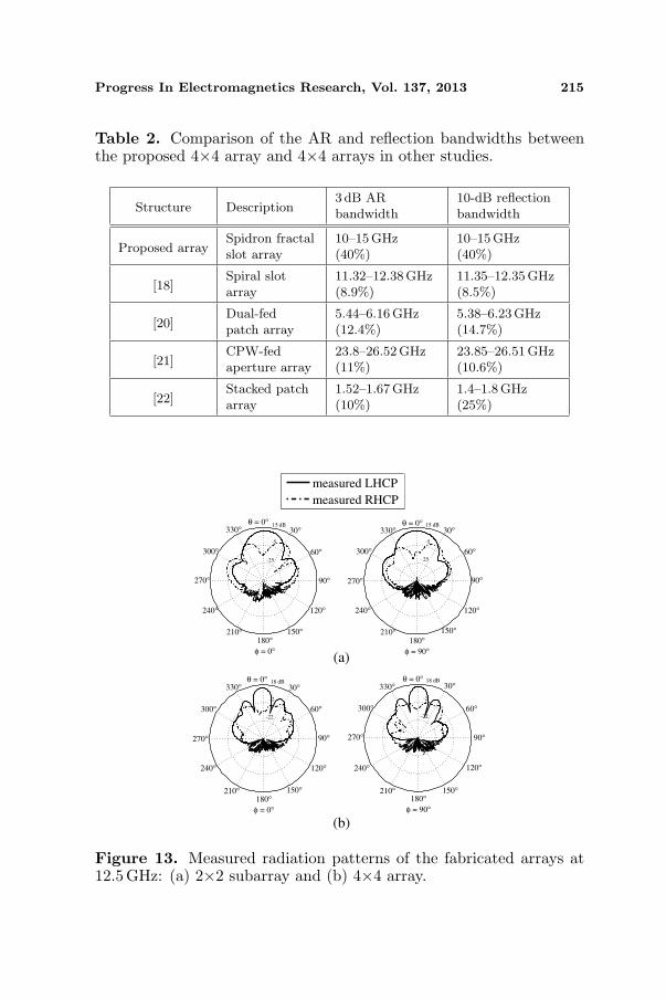
Figure 12(a) shows the simulated and measured reflectioncoefficients of the 4×4 array configuration. The simulated 10-dBreflection bandwidth ranges from 10.4 to 15 GHz, while the measured10-dB reflection bandwidth covers the entire frequency range. Thesimulated and measured results for the AR and gain are shownin Fig. 12(b); overall, they agree well with each other. We findthat the CP performance is further enhanced by applying sequentialrotation feeding into the four 2×2 subarrays, as both the simulatedand measured ARs are lower than 1.5 dB over the entire measuredfrequency range. The measured broadside gain varies from 11.31 dBat 10.3 GHz to 15.63 dB at 12.6 GHz. Table 2 shows a comparison ofthe proposed 4×4 array antenna and the antennas presented in earlierworks [18, 20–22] in terms of the reflection and 3 dB AR bandwidths.The proposed 4×4 array utilizing a Spidron fractal slot has broaderbandwidth compared to the previous 4×4 arrays.
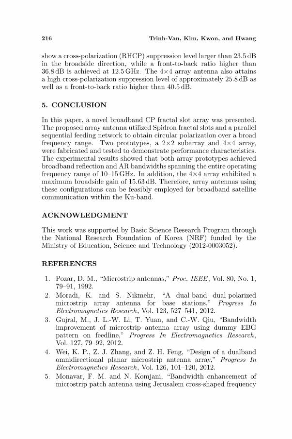
The measured CP radiation patterns along two elevation cuts(xz- and yz-planes) of the fabricated 2×2 subarray and 4×4 array areillustrated in Fig. 13. The experimental results for the 2×2 subarray
Progress In Electromagnetics Research, Vol. 137, 2013 215
Table 2. Comparison of the AR and reflection bandwidths betweenthe proposed 4×4 array and 4×4 arrays in other studies.
Structure Description3 dB ARbandwidth
10-dB reflectionbandwidth
Proposed arraySpidron fractalslot array
10–15GHz(40%)
10–15GHz(40%)
[18]Spiral slotarray
11.32–12.38 GHz(8.9%)
11.35–12.35 GHz(8.5%)
[20]Dual-fedpatch array
5.44–6.16GHz(12.4%)
5.38–6.23GHz(14.7%)
[21]CPW-fedaperture array
23.8–26.52GHz(11%)
23.85–26.51 GHz(10.6%)
[22]Stacked patcharray
1.52–1.67GHz(10%)
1.4–1.8 GHz(25%)
(a)
(b)
Figure 13. Measured radiation patterns of the fabricated arrays at12.5GHz: (a) 2×2 subarray and (b) 4×4 array.
216 Trinh-Van, Kim, Kwon, and Hwang
show a cross-polarization (RHCP) suppression level larger than 23.5 dBin the broadside direction, while a front-to-back ratio higher than36.8 dB is achieved at 12.5 GHz. The 4×4 array antenna also attainsa high cross-polarization suppression level of approximately 25.8 dB aswell as a front-to-back ratio higher than 40.5 dB.
5. CONCLUSION
In this paper, a novel broadband CP fractal slot array was presented.The proposed array antenna utilized Spidron fractal slots and a parallelsequential feeding network to obtain circular polarization over a broadfrequency range. Two prototypes, a 2×2 subarray and 4×4 array,were fabricated and tested to demonstrate performance characteristics.The experimental results showed that both array prototypes achievedbroadband reflection and AR bandwidths spanning the entire operatingfrequency range of 10–15 GHz. In addition, the 4×4 array exhibited amaximum broadside gain of 15.63 dB. Therefore, array antennas usingthese configurations can be feasibly employed for broadband satellitecommunication within the Ku-band.
ACKNOWLEDGMENT
This work was supported by Basic Science Research Program throughthe National Research Foundation of Korea (NRF) funded by theMinistry of Education, Science and Technology (2012-0003052).
REFERENCES
1. Pozar, D. M., “Microstrip antennas,” Proc. IEEE , Vol. 80, No. 1,79–91, 1992.
2. Moradi, K. and S. Nikmehr, “A dual-band dual-polarizedmicrostrip array antenna for base stations,” Progress InElectromagnetics Research, Vol. 123, 527–541, 2012.
3. Gujral, M., J. L.-W. Li, T. Yuan, and C.-W. Qiu, “Bandwidthimprovement of microstrip antenna array using dummy EBGpattern on feedline,” Progress In Electromagnetics Research,Vol. 127, 79–92, 2012.
4. Wei, K. P., Z. J. Zhang, and Z. H. Feng, “Design of a dualbandomnidirectional planar microstrip antenna array,” Progress InElectromagnetics Research, Vol. 126, 101–120, 2012.
5. Monavar, F. M. and N. Komjani, “Bandwidth enhancement ofmicrostrip patch antenna using Jerusalem cross-shaped frequency

Progress In Electromagnetics Research, Vol. 137, 2013 217
selective surfaces by invasive weed optimization approach,”Progress In Electromagnetics Research, Vol. 121, 103–120, 2011.
6. Asimakis, N. P., I. S. Karanasiou, and N. K. Uzunoglu,“Non-invasive microwave radiometric system for intracranialapplications: A study using the conformal L-notch microstrippatch antenna,” Progress In Electromagnetics Research, Vol. 117,83–101, 2011.
7. Wang, X., M. Zhang, and S.-J. Wang, “Practicability analysisand application of PBG structures on cylindrical conformalmicrostrip antenna and array,” Progress In ElectromagneticsResearch, Vol. 115, 495–507, 2011.
8. Tiang, J. J., M. T. Islam, N. Misran, and J. S. Mandeep, “Circularmicrostrip slot antenna for dual-frequency RFID application,”Progress In Electromagnetics Research, Vol. 120, 499–512, 2011.
9. Garcia-Aguilar, A., J.-M. Inclan-Alonso, L. Vigil-Herrero, J.-M. Fernandez-Gonzalez, and M. Sierra-Perez, “Low-profile dualcircularly polarized antenna array for satellite communications inthe X band,” IEEE Trans. Antennas Propag., Vol. 60, No. 5, 2276–2284, 2012.
10. Lau, P.-Y., K. K.-O. Yung, and E. K.-N. Yung, “A low-costprinted CP patch antenna for RFID smart bookshelf in library,”IEEE Trans. Ind. Electron., Vol. 57, No. 5, 1583–1589, 2010.
11. Wang, P., G. Wen, J. Li, Y. Huang, L. Yang, and Q. Zhang,“Wideband circularly polarized UHF RFID reader antennawith high gain and wide axial ratio beamwidths,” Progress InElectromagnetics Research, Vol. 129, 365–385, 2012.
12. Rao, P. N. and N. V. S. N. Sarma, “Fractal boundary circularlypolarised single feed microstrip antenna,” Electron. Lett., Vol. 44,No. 12, 713–714, 2008.
13. Dong, Y., H. Toyao, and T. Itoh, “Compact circularly-polarizedpatch antenna loaded with metamaterial structures,” IEEE Trans.Antennas Propag., Vol. 59, No. 11, 4329–4333, 2011.
14. Tang, X., H. Wong, Y. Long, Q. Xue, and K. L. Lau, “Circularlypolarized shorted patch antenna on high permittivity substratewith wideband,” IEEE Trans. Antennas Propag., Vol. 60, No. 3,1588–1592, 2012.
15. Rezaeieh, S. A. and M. Kartal, “A new triple band circularlypolarized square slot antenna design with crooked T and F-shapestrips for wireless applications,” Progress In ElectromagneticsResearch, Vol. 121, 1–18, 2011.
16. Sze, J.-Y. and S.-P. Pan, “Design of broadband circularly
218 Trinh-Van, Kim, Kwon, and Hwang
polarized square slot antenna with a compact size,” Progress InElectromagnetics Research, Vol. 120, 513–533, 2011.
17. Zarifi, D., H. Oraizi, and M. Soleimani, “Improved performance ofcircularly polarized antenna using semi-planar chiral metamaterialcovers,” Progress In Electromagnetics Research, Vol. 123, 337–354,2012.
18. Nakano, H., K. Nakayama, H. Mimaki, J. Yamauchi, andK. Hirose, “Single-arm spiral slot antenna fed by a triplatetransmission line,” Electron. Lett., Vol. 28, No. 22, 2088–2090,1992.
19. Hall, P. S., “Application of sequential feeding to wide bandwidth,circularly polarised microstrip patch arrays,” Proc. Inst. Elect.Eng. Microw., Antennas Propag., Vol. 136, No. 5, 390–398, 1989.
20. Evans, H., P. Gale, and A. Sambell, “Performance of 4×4sequentially rotated patch antenna array using series feed,”Electron. Lett., Vol. 39, No. 6, 493–494, 2003.
21. Soliman, E. A., S. Brebels, E. Beyne, and G. A. E. Vandenbosch,“Sequential-rotation arrays of circularly polarized apertureantennas in the MCM-D technology,” Microw. Opt. Technol. Lett.,Vol. 44, No. 6, 581–585, 2005.
22. Kaffash, S. and M. Kamyab, “A sequentially rotated RHCPstacked patch antenna array for INMARSAT-M land applica-tions,” Proc. 6th European Conf. Antennas Propag. (EUCAP),1–4, Prague, Czech Republic, 2012.
23. Hwang, K. C., “Broadband circularly-polarised Spidron fractalslot antenna,” Electron. Lett., Vol. 45, No. 1, 3–4, 2009.