Circular Beam
24
Design of Circular Beams The Islamic University of Gaza Department of Civil Engineering Design of Special Reinforced Concrete Structures ENGC 6353 Dr. Mohammed Arafa 1
-
Upload
syed-sikandar-shah -
Category
Documents
-
view
64 -
download
2
description
Civil engineering
Transcript of Circular Beam

Design of Circular Beams
The Islamic University of GazaDepartment of Civil EngineeringDesign of Special Reinforced Concrete Structures
ENGC 6353 Dr. Mohammed Arafa 1

Circular Beams
They are most frequently used in circular reservoirs, spherical dome, curved balconies … etc.
Circular beams loaded and supported loads normal to their plans.
The center of gravity of loads does not coincide with the centerline axis of the member.
ENGC 6353 Dr. Mohammed Arafa 2

Circular Beams
Circular beam are subjected to torsional moments in addition to shear and bending moment
The torsional moment causes overturning of the beams unless the end supported of the beams are properly restrained.
ENGC 6353 Dr. Mohammed Arafa 3

Semi-circular beam simply supported on three equally spaced supports
ENGC 6353 Dr. Mohammed Arafa 4
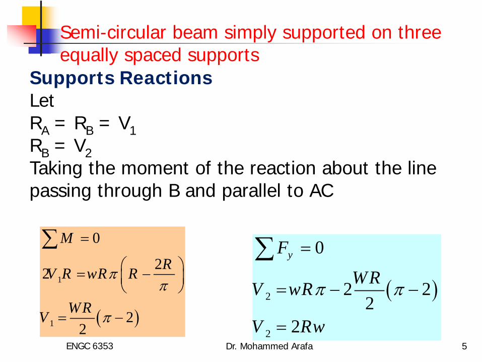
Supports Reactions LetRA = RB = V1RB = V2Taking the moment of the reaction about the line passing through B and parallel to AC
( )
1
1
0
22
22
M
RV R wR R
WRV
ππ
π
=
= −
= −
∑
( )2
2
0
2 22
2
yFWRV wR
V Rw
π π
=
= − −
=
∑
Semi-circular beam simply supported on three equally spaced supports
ENGC 6353 Dr. Mohammed Arafa 5
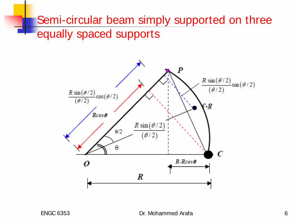
Semi-circular beam simply supported on three equally spaced supports
ENGC 6353 Dr. Mohammed Arafa 6

Taking the bending moment at point P at angle θfrom the support say, C equal:
( ) ( )
( ) ( )
( ) ( )
1
2 2
2 2
sin / 2sin sin / 2
/ 2
2 sin 2 sin / 22
2sin 2sin / 2
2
RM V R wR
wRM R wR
M wR
θ
θ
θ
θθ θ θ
θ
π θ θ
πθ θ
= −
= − −
− = −
Semi-circular beam simply supported on three equally spaced supports
ENGC 6353 Dr. Mohammed Arafa 7

Maximum negative moment occurs at point B
max.
2
( )2
0.429
ve B
B
M M at
M wR
πθ− = =
= −
Maximum Positive moment
( ) ( ) ( )2
2max
. ( 0)
2cos 2sin / 2 cos / 2 0
22tan 29 43'
20.1514
vedMMax M whered
dM wRd
M wR
θ
θ
θπ
θ θ θθ
πθ θ
+ = =
− = − =
−
= =
=
Semi-circular beam simply supported on three equally spaced supports
ENGC 6353 Dr. Mohammed Arafa 8

Torsional Moment at point P
Semi-circular beam simply supported on three equally spaced supports
( ) ( ) ( )1
2
2max.
sin / 2cos cos / 2
/ 2
2 2 cos sin2 2
dTThesection of max. torsion 0d
dT 0 59 26 'd
0.1042
RT V R R wR R
T wR
at
T wR
θ
θ
θ
θ
θθ θ θ
θ
π π θ θ θ
θ
θθ
= ⋅ − − −
− − = − − +
=
= =
=
ENGC 6353 Dr. Mohammed Arafa 9

Circular beams loaded uniformly and supported on symmetrically placed columns
A
B
θ
ENGC 6353 Dr. Mohammed Arafa 10

Circular beams loaded uniformly and supported on symmetrically placed columns
ENGC 6353 Dr. Mohammed Arafa 11

Consider portion AB of beam between two consecutive columns A and B be θ
The load on portion AB of beam =wRθ
The center of gravity of the load will lie at a distance from the center
Let M0 be the bending moment and V0 be the shear at the supports
Circular beams loaded uniformly and supported on symmetrically placed columns
R sin( /2) ( /2) θ θ
ENGC 6353 Dr. Mohammed Arafa 12

From geometry
The moment M0 at the support can be resolved along the line AB and at right angle to it. The component along line AB is and at right angle of it.
Taking the moment of all forces about line AB
Circular beams loaded uniformly and supported on symmetrically placed columns
0 / 2V wRθ=
0M sin( /2)θ 0M cos( /2)θ
ENGC 6353 Dr. Mohammed Arafa 13

Taking the moment of all forces about line AB
Circular beams loaded uniformly and supported on symmetrically placed columns
( ) ( ) ( )
( )( ) ( )
( )
( )
0
20
20
sin / 22 sin / 2 co s / 2
/ 2
sin / 2 co s / 22sin / 2 / 2 2sin / 2
1 cot / 22
RM wR R
M wR
M wR
θθ θ θ
θ
θ θθ θθ θ θ
θ θ
= −
= ⋅ − = −
ENGC 6353 Dr. Mohammed Arafa 14

Shear force and bending moment at point P, at angle φ from the support
2 2PwRV wR wRθ θφ φ = − = −
• Load between points A and P is wRφ• Shearing force at point P
ENGC 6353 Dr. Mohammed Arafa 15

The direction of vector representing bending moment at point P will act along line PO
Shear force and bending moment at point P
( ) ( )
( ) ( )
( ) ( )
( )
( )
0 0
22 2 2
2 2
2
2
sin / 2sin cos sin / 2
/ 2
sin 1 cot / 2 cos 2 sin / 22 2
sin cos cot / 2 cos 2sin / 22 2
since cos 2sin / 2 1
1 sin cot / 2 cos2 2
RM V R M wR
wRM wR wR
M wR
M wR
φ
φ
φ
φ
φφ φ φ φ
φθ θφ θ φ φ
θ θφ φ θ φ φ
φ φ
θ θφ θ φ
= − −
= − − − = − + − + =
= − + +
ENGC 6353 Dr. Mohammed Arafa 16

The direction of vector representing torsion at point P will act at right angle to line PO
Shear force and bending moment at point P
( ) ( ) ( )
( ) ( )
( ) ( ) ( ) ( )
( ) ( )
0
2
2 2 2 2
2 2 2 2
sin / 2sin cos cos / 2
2 / 2
since cos 1 cos 2 sin / 2
21 co t / 2 sin sin / 2 1 sin / 2 co s / 22
2 11 cot / 2 sin sin / 2 1 sin2 2
RwRT M R R wR R
R R R R
T wR wR wR
T wR wR wR
φ
φ
φ
φθφ φ φ φφ
φ φ φ
θ θ φ θ φ φ φ φφ
θ θ φ θ φ φ φφ
= − − + −
− = − =
= − − + −
= − − + −
( ) ( )
( ) ( )
( )
( )
2 2
2 2
2
2
sin cot / 2 sin sin / 2 sin2
cot / 2 sin sin / 22
since 2sin / 2 1 cos
cos sin cot / 2 sin2 2 2
T wR
T wR
T wR
φ
φ
φ
θφ θ φ θ φ φ φ
θφ θ φ θ φ
φ φ
θ θ θφ φ φ θ φ
= − − + − = − −
= −
= − + − − ENGC 6353 Dr. Mohammed Arafa 17

To obtain maximum value of torsional moment
Shear force and bending moment at point P
( ) ( ) ( )
( )
( )
0
2
2
sin / 2sin cos cos / 2
2 / 2
1 sin sin cot / 2 cos 02 2
1 sin sin cot / 2 cos 02 2
RwRM R R wR R
dTwR
d
M wR
φ
φ
φθφ φ φ φφ
θ θφ φ θ φφ
θ θφ φ θ φ
= − − + −
= − − − = = − − − =
0dTd
φ
φ=
i.e. point of maximum torsion will be point of zero moment
ENGC 6353 Dr. Mohammed Arafa 18

Internal Forces in Circular beams Using polar coordinate
A
B
ϕP
as r= constant
dV w ds rddsdV wrdsdM dT Vds dr
dT Tdr rdM T Vds r
dM T Vrd
ϕ
ϕ
= − =
= −
+ =
=
+ =
+ =
ENGC 6353 Dr. Mohammed Arafa 19

Internal Forces in Circular beams Using polar coordinate
The component of the moment M along ds in the radial direction must be equal to the difference of the torsional moments along the same element
MdsdT Mdr
dT Md
ϕ
ϕ
= =
=
This means that the torsional moment is maximum at point of zero bending moment
ENGC 6353 Dr. Mohammed Arafa 20

Internal Forces in Circular beams Using polar coordinate
Differentiating the equation
The solution of this deferential equation gives
( )22
2
22
2
d Vrd M dT dVr r wd d d dd M M wrd
ϕ ϕ ϕ ϕ
ϕ
+ = = = −
+ = −
dM T Vrdϕ
+ =
2sin cosM A B wrϕ ϕ= + −
ENGC 6353 Dr. Mohammed Arafa 21

Internal Forces in Circular beams Using polar coordinate
The constants can be determined from conditions at supports
The internal forces are in this manner statically indeterminate. In many cases, they can be determined from the conditions of equilibrium alone because the statically indeterminate values are either known or equal to zero.
2sin cosM A B wrϕ ϕ= + −
ENGC 6353 Dr. Mohammed Arafa 22

Circular beams loaded uniformly and supported on symmetrically n placed columns
The bending moment and shearing force V at any section at an angle ϕ from the centerline between two successive supports are given by:
0 022
2n nrw rwR Vn n
π πϕ ϕ
π π
= =
= = ±
2
0
2
0
cos 1sin
sinsin
M r wn
T r wn
V rw
π ϕϕ
π ϕ ϕϕ
ϕ
= −
= − −
= −ENGC 6353 Dr. Mohammed Arafa 23

Circular beams loaded uniformly and supported on symmetrically n placed columns
# of Supports R V θ K K` K``Angle
for Max Torsion
4 P/4 P/8 90 0.137 0.07 0.021 19 215 P/5 P/10 72 0.108 0.054 0.014 15 456 P/6 P/12 60 0.089 0.045 0.009 12 447 P/7 P/14 51 3/7 0.077 0.037 0.007 10 45 8 P/8 P/16 45 0.066 0.030 0.005 9 339 P/9 P/18 40 0.060 0.027 0.004 8 3010 P/10 P/20 36 0.054 0.023 0.003 7 3012 P/12 P/24 30 0.045 0.017 0.002 6 21
2support
` 2Midspan
`` 2max
2P rwM KwR
M K wR
T K wR
π
θ
θ
θ
=
=
=
=O
Mmax(+ve)
Tmax
Tmax
Mmax(-ve)
V
Mmax(-ve)
Vmax
φ`
θ/2
ENGC 6353 Dr. Mohammed Arafa 24