


Circuits Assembly - November 2006 - Digital...
55
Click here to view this issue. Welcome to the November 2006 digital edition of Circuits Assembly.
Transcript of Circuits Assembly - November 2006 - Digital...

Click here to view this issue.
Welcome to the November 2006 digital edition of Circuits Assembly.

NOVEMBER 2006 circuitsassembly.comcircuitsassembly.com
Guidelines for Outsourcing Board Layout
Lowest Total Cost?When the U.S. is Best
Eutectics’ Effect on Solder JointAppearance
Achieving business growthand customer satisfaction
Going with the Flow
Achieving business growthand customer satisfaction
Going with the Flow
Thin Packages: The New Model, pg. 16

FEATURESProcurement
24 ‘Re-Sourcing’ Outsourced Electronics It’s called a “priceberg”: 80% of the risk may be hidden below the waterline in startup andramp-down, where management costs per units sold tend to be the highest. Building aharmonious, minimally disruptive dual-sourcing strategy requires an understanding ofpriceberg composition.
Ed Grimes
Customer Service
28 What Your Field Service RepresentativeWants You to KnowThey are like firefighters. When you need them, you need them now. The results can be tense,technical – and funny.
Frank Murch
PCB Design Trends
32 Understanding Outsourced PCB LayoutHere are an EMS provider’s insights into the stages of PCB layout, for which key componentsinclude corporate standards and OEM-EMS collaboration.
Paul Barsley
Cover Story
36 Maintaining Customer Satisfaction during EMS Acquisition IntegrationCustomers of EMS firms aren’t buying an end product; they are buying the capabilities,systems, processes and internal culture used to manufacture their product. This in turn putspressure on the EMS company to manage expectations – and move quickly.
Todd Baggett
Case Study: Preforms
38 In the Hot ZoneIn the competitive oil and gas drilling industry, a project’s success – and a company’s reputation– can hinge on seemingly insignificant variables such as a few degrees of temperature on acircuit board. That was quite literally the issue facing a major oil-exploration company as itperformed data-collection tests at a client’s wells sunk deep in the Indian Ocean.
Cheryl Ross
NOVEMBER 2006 – Vol. 17 No. 11
ON THE COVER: EPIC’s wavesolder equipment changes profilesbased on each assembly’s bar codes.
NOVEMBER 2006 circuitsassembly.comcircuitsassembly.com
Guidelines for Outsourcing Board Layout
Lowest Total Cost?When the U.S. is Best
Eutectics’ Effect on Solder JointAppearance
Achieving business growthand customer satisfaction
Going with the Flow
Achieving business growthand customer satisfaction
Going with the Flow
Thin Packages: The New Model, pg. 16
Phot
o co
urte
sy E
PIC
Tech
nolo
gies
FIRST PERSON
4 Caveat LectorWhere will you be next fall?Mike Buetow
12 Talking HeadsJuki Automation Systems’ Bob Black.Mike Buetow
MONEY MATTERS
14 Focus on BusinessFormal programs for sharing customerinformation.Susan Mucha
TECH TALK
16 On the ForefrontAnorexic packaging.E. Jan Vardaman
18 Screen PrintingAutomated stencil inspection.Clive Ashmore
20 Better ManufacturingGetting what you want.Peter Grundy
40 Tech TipsLowering wire bonding defect rates below 100 ppm. American Competitiveness Institute
42 Wave SolderingThe role of eutectics. Gerjan Diepstraten
43 Test and InspectionUsing x-ray laminography on PTH joints.Jeremy Jessen
44 Process DoctorDendritic growth.Terry Munson
45 Equipment AdvancesInovaxe’s inventory control tools.
48 Technical Abstracts
DEPARTMENTS
6 Industry News 46 Product Spotlight10 Market Watch 47 Classifieds31 Assembly Insider 48 Ad Index

Siemens Energy & Automation, Inc.
SIPLACE
Introducing the new SIPLACE D-Series
Siemens introduces its new SIPLACE D-Series platform with digital vision. This new platform
not only features an especially attractive price-performance ratio, but also several signifi-
cant innovative features of the SIPLACE X-Series.
The digital SIPLACE vision system comes standard – it recognizes components more quickly
and reliably for faster production. Components can also be recognized externally for a faster
NPI. The flexible dual-conveyor transport makes it easy to process circuit boards of different
sizes and adapt from one to another product fast and easily.
Visit our website at www.siplace.com.

circuitsassembly.com Circuits Assembly NOVEMBER 2006 3
circuitsassembly.com
Editorial OfficeCircuits Assembly
2400 Lake Park Drive, Ste. 440,Smyrna, GA 30080
678-589-8800
Editor-in-Chief: Mike Buetow(617) 327-4702, [email protected]
Associate Editor: Chelsey Drysdale(678) 589-8846, [email protected]
Production Manager/Managing Editor:Javier Longoria
Director of Audience Development: Jennifer SchulerMarketing Manager: Ronda Faries
Exhibit Sales Manager: Brooke AnglinPublisher: Pete Waddell
Group Sales Director: Susan Jones(404) 822-8900, [email protected]
Sales Associate: Kamden Robb(678) 589-8843, [email protected]
Asia (except Korea): Jan Vardaman, Tech Search International
(512) 372-8887, [email protected]
Korea: Young Media82 2 756 4819, [email protected]
Circulation Inquiries:email: [email protected]
fax: (918) 496-9465
Reprints:Electronic: [email protected]
Print: Lauren Siegel, FosteReprints866-879-9144 ext. 137; fax: 219-561-2031
List Rental:Jennifer Schuler, (918) 496-1476; fax (918) 496-9465
Editorial Advisory Board:John D. Borneman, Delphi Delco Electronics
Rich Breault, Lightspeed ManufacturingSue Mucha, Powell-Mucha Consulting
Chrys Shea, Cookson Electronics
UP Media Group, Inc.President: Pete Waddell
PCB Show Group: (678) 589-8800
Subscription PolicyCircuits Assembly (ISSN 1054-0407/GST124513185/Agreement
#1419676) is distributed without charge to qualified subscribers. To all oth-ers in the USA and Canada: US$80 per year. Other countries: US$145 peryear (air service included, payment required in advance). Single copiesUS$8.50. Send requests for qualification forms and changes of address(include old label) to: CIRCUITS ASSEMBLY, P.O. Box 35646, Tulsa, OK74153-0646, email: [email protected], fax (918) 496-9465.Periodicals postage paid at Atlanta, GA 30339 and additional mailingoffices.
Reproduction of text and illustrations is notallowed without express written permission. Autho-rization to photocopy items for internal or personaluse, or the internal or personal use of specific clients, is granted by UPMedia Group, Inc. for libraries and other users registered with the Copy-right Clearance Center (CCC) Transactional Reporting Service, providedthat the base fee of $2.00 per copy, plus $0.25 per page is paid direct-ly to CCC, 21 Congress St., Salem, MA 01970. 0009-7306/86, $2.00 +$0.25. 16mm microfilm, 35mm microfilm, 105mm microfiche and arti-cle and issue photocopies are available from University MicrofilmsInternational, 300 N. Zeeb Rd., Ann Arbor, MI 48106 (313) 761-4700.Canadian GST Permit 124513185.
Opinions expressed by authors are not necessarily those of the pub-lisher, and this publication can accept no responsibility in connectionwith any liability that might develop as a result of articles published.
Circuits Assembly is published monthly by UP Media Group, Inc., 2400Lake Park Drive, Suite 440, Smyrna, GA 30080. POSTMASTER: Please sendchanges of address to CIRCUITS ASSEMBLY, P.O. Box 35646, Tulsa, OK74153-0646.
Complex components need advanced protection.
When you need to precisely spray anddispense liquid coatings, SCS Precisioncoatselective spray coating systems provide
maximum accuracy and flexibility. Thesystems apply solvent-based, water-
based and 100% solids coatings via three to fiveaxes. Internal Ethernet connectivity is standard, andoptional features meet any production requirement.
SCS Precisioncoat systems connect seamlessly with SCS thermal and UV cure units, enablingcomponents to move from coating to curing
without operator intervention.
Contact SCS to find out more about our innovative solutionsfor your advanced technologies.
World Headquarters (US): 317.244.1200 www.scscoatings.com

set up is highly competitive, but a trade show goes waybeyond its past experience of technical conferences andtabletops, and there are understandably questions aboutjust how they are going to pull this off. While at thiswriting it seems highly unlikely, I think it would be inthe best interests of the industry for the shows to remainas one for now.
Agents of change. Think lead-free is oh-so-last-July?Think again. Sessions on lead-free at SMTAI wereabsolutely brimming. Unfortunately, the popularity ofthose sessions tended to overshadow the event’s unusual-ly strong management program.
For years I’ve heard numerous complaints about thereported “inability” of the U.S. to compete with low-costlabor regions, or how other locales (read: the EU) engagein unfair trade practices. But I did sit through a first-ratesession at SMTAI that brought together a handful of thebrightest and sharpest proponents of how Americancompanies can compete.
Two highlights of the five-hour program were:• Bill Eagen, leader of Deloitte Consulting’s Outsourcing
Advisory Practice, who revealed that while outsourc-ing remains an effective strategy for smaller (less than$10 billion in revenue) businesses and especially thosein the $500 million range, the mix of unanticipatedcosts and problems often outweighs the benefits forcompanies above $10 billion in revenue. Through acomprehensive survey, Deloitte found contractorshave problems creating an economic model that cansustain changes in the customer’s business. In short,while contractors handle the basics well, they tend tolack flexibility, to the frustration of customers. Gover-nance, he says, “is critical.”
• Dr. Aroon Tungare, who heads Motorola’s advanceddevelopment lab, followed him with a discussionabout how intellectual property and innovation maybe used to realize a sustainable competitive advantage.The only downside was the attendance: Just a hand-
ful of folks showed up. However, when I expressed mydismay to session chair Matt Holzmann, president ofChristopher Associates, he replied: “Don’t concentrateon the numbers. Push ‘change.’ ” Keynoter Tom Borkeswas even more succinct, observing that “whining is not avalue-added activity.”
Fair enough. And the next time someone starts gripingabout China or India or Taiwan or the EU, I’ll be sure toask what they’ve personally done to change it.
The Assembly Technology Expo show hadn’t evendrawn to a close before the battle began heatingup over where exhibitors will put their trade show
dollars next year.In one corner is the incumbent AT Expo, now run by
a new owner, L.A.-based Canon Communications. In theother is the SMTA trade association, which is launching itsown event in 2007.
SMTA and Reed Exhibition, the previ-ous owner of AT Expo, were paired since1999 and had cobbled together a solid andgrowing, if somewhat broadly focused,event just outside Chicago. However, whenCanon purchased AT Expo from Reed earli-er this year, the former decreed that goingforward, it would sever a large incentive(read: guaranteed money) that had provid-ed SMTA with as much as a quarter of itsannual operating budget.
For SMTA, the lack of certain fundingmade AT Expo less attractive than going italone. Thus, SMTA’s board is opting tomove its technical conference, SMTAI, to
Orlando and adding an expo focused on electronicsassembly. The new show launches next October.
Most exhibitors in Chicago expressed surprise at theimpending divorce, and no clear preference has yetemerged. Some voiced concern about the growing num-ber of shows. Others countered they’d prefer severalregional shows to a single annual event. Many pointed toCanon’s decision to colocate its National ManufacturingWeek event with AT Expo next year as a step in thewrong direction, as the 40,000 or so expected attendeeswould dilute the electronics assembly audience, whilealso making it even more difficult to secure hotel space(hello, Rockford!) and other amenities. Still othersyearned for the event to move – but to Las Vegas.
In response, director of marketing Dan Cutrone toldme Canon has secured some 3,000 hotel rooms within thevillage of Rosemont for next year’s show, which will cover“100% of the needs of the attendees.” He also called erro-neous suggestions that Canon simply pulled the plug onthe SMTA.“[F]or SMTA to achieve that revenue platformin other ways … [w]e looked at how we could furtherreduce the cost: Free marketing, free hotel, free registra-tion services, and SMTA would keep 100% of the [confer-ence] revenue.” And if SMTA were to change its mind,Canon would welcome the trade group back, he said.
All things being equal, I would rather see trade showrevenues go into the pocket of the organization that willdutifully reinvest those monies in the industry: SMTA.But it’s not that simple. The pricing schedule SMTA has
Come Next Fall, Chicago or Orlando?Caveat Lector
Mike Buetow, [email protected]
4 Circuits Assembly NOVEMBER 2006 circuitsassembly.com

Overheating:• Increased Power
• Decreased Package Size
Solder TIM for heat dissipation:• Flux-Coated SAC
Preforms
• Compliant Alloys
Voiding:• Via-in-pad Voiding
• CSP Printing
Indium5.1 SeriesNo-Clean Pb-FreeSolder Paste• Low-voiding• Print Deposit
Repeatability• Excellent
Response-to-Pause
Incomplete Barrel Fill:• Reduced Wetting
Ability Using Pb-Free Alloys
• Insuffi cient Solder Volume
Wave Solder Products:• WF7742 Wave Flux
• Pin-In-Paste+ with 0603 Preforms
Cracking:• Brittle
Pb-Free Alloys
• Reduced Joint Size
NF260 No-FlowUnderfi ll:• Air Refl ow
• High-strength
• Low-voiding
• Reworkable
Problem? Solved: [email protected] • www.indium.com/reliability
S O L D E R

6 Circuits Assembly NOVEMBER 2006 circuitsassembly.com
IndustryNEWS
Jabil to Take $120M in Restructuring ChargesST. PETERSBURG, FL – Top tier EMS provider Jabil Circuit (jabil.com) will take a $120.2 million
fourth-quarter restructuring charge as it prepares to close certain plants, according to a companySEC filing. While industry speculation has centered on the possible closing of one to two plants inthe U.S., the filing was not specific, but implied that certain changes would take place abroad.
In the filing, Jabil disclosed it would take $81.2 million in charges for employee severance andbenefit costs, contract termination costs and other related restructuring costs. The company willtake further charges of $35.6 million for material impairment costs and $3.4 million for fixed assetimpairment costs.
The exact timing of the remaining estimated range of restructuring and impairment costs, as wellas the remaining estimated cost ranges by category type, have not been finalized. Jabil explainedthat restructuring decisions at certain foreign plants are still subject to consultation with employ-ees and their representatives.
The company announced in July that it would take charges of $200 million to $250 millionbetween its fourth fiscal quarter and throughout fiscal 2007.
Separately, a class action lawsuit filed in U.S. District Court in Florida claims Jabil misrepresent-ed its financial performance between Sept. 19, 2001 and June 21, 2006, thus artificially inflatingits stock price. On behalf of current and former Jabil shareholders, the Howard G. Smith law firmalleges that Jabil violated federal securities laws by issuing a series of material misrepresentationsto the market. No class has yet been certified.
Study: U.S. Maintains Lead in Electronic Design,China Gaining
EL SEGUNDO, CA – The U.S. in 2006 is expected to maintain its lead in the worldwide electronicsequipment design with the nation’s activities in this area, driving the most semiconductor purchas-ing of any country, according to new data from iSuppli Corp. (isuppli.com). However, China’s rapidgrowth in electronic-design-generated semiconductor purchasing activity is continuing, and the coun-try is closing the gap, according to the research firm.
“Design of electronic goods leads directly to equipment production, which in turn drives semicon-ductor purchasing. Companies that engage in design of electronic equipment, such as PCs, mobilephones and televisions also are responsible for specifying the use of particular chips in the productsbeing developed,” stated Min-Sun Moon, OEM spend analyst for iSuppli. “Thus, these companies andthe nations where they operate have a major influence on global semiconductor spending.”
Electronic system design in the U.S. is expected to drive 34.9% of global semiconductor purchas-ing in 2006, amounting to $62.1 billion worth of chip sales for the year. This represents a 6.6%increase from $58.3 billion in 2005.
“The fact the United States is the largest nation for electronic design contrasts sharply with thecountry’s propensity to outsource actual manufacturing to other countries,” Moon commented.
“While actual production of electronic equipment is decreasing in the United States, the nation’sdesign activity that drives semiconductor spending is on the rise. However, as a percentage of world-wide semiconductor spending, the United States’ design-inspired chip purchasing will actually declineslightly in 2006, decreasing from 35.2% in 2005,” Moon continued.
Japan is expected to maintain its second-place ranking in 2006, with its design activity generating24.9% of worldwide chip sales, followed by Taiwan at 8.6%.
Of the 10 largest nations, China/Hong Kong is growing the fastest, at 26.1%. Electronic designactivities in the region will influence 6.5% of worldwide semiconductor purchasing in 2006, com-pared to 5.6% in 2005. This will cause China/Hong Kong to surpass Germany and South Korea tobecome the world’s fourth-largest national influencer of electronic-design-generated semiconductorspending in 2006.
Extensive work in the computer design area drives China/Hong Kong’s advance. Furthermore, com-panies increasingly are moving operations out of Western Europe and into China, boosting thenation’s activities in this area.
Digi-Key Corp. (digikey.com) has signed aworldwide distribution deal covering Anteno-va Ltd.’s (antenova.com) integrated antennaproduct line.
The MicroElectronics Packaging andTest Engineering Council (meptec.org) willhold its annual packaging roadmaps sympo-sium Nov. 16 in San Jose. IC Packaging & TestRoadmaps: Device Trends Impact on Packaging& Test Technology and Supply Chain will over-lay IC device trends with the associated currentand future technology solutions for packagingand test and will also explore challenges asso-ciated with demands for full turnkey supplychain services.
Eunil H.A.Americas Inc. (eunil.com) will dis-tribute Jaesung Precision Co. (jaesung.com)spare parts for automatic insertion and SMDsystems from such makers as Panasonic, Fuji,KME, Sanyo, Juki, Hitachi and Samsung.
EasySpheres (easyspheres.com) will inven-tory and sell Kester’s (kester.com) full productoffering of Ultra-Spheres and TSF interconnectfluxes.
Sanmina-SCI (sanmina-sci.com) will assem-ble an integrated optical component designedby Enablence Technologies (enablence.com)and used in certain modems. Financial termswere not disclosed.As a result of the deal, San-mina-SCI will hire additional workers and make“significant” upgrades to its Allen, TX, plant.
Allied Electronics (alliedelec.com) will dis-tribute Kemet’s (kemet.com) line of capacitorsand tantalums.
Mercury Computer (mc.com) selectedAssurX’s (assurx.com) CATSWeb OnDemandSolutions for global quality management at 15locations.
DEK (dek.com) is now sole distributor forMicroStencil (microstencil.com) in Asia andthe Americas. DEK’s Platinum line will includethe entire MicroStencil product portfolio.
CorrectionIn October, we misidentified Cookson's Steve
Brown as Valor's Howard Rupprecht (IndustryNews, pg. 9). CIRCUITS ASSEMBLY regrets theerror.
In Brief
Edited by Mike Buetow

Knowledge in process
It’s in the Box.
The MPM AccuFlex stencil printer is suited for moderate volume, high-mix
printing, combining accuracy with unparalleled flexibility in a cost-effective
and compact footprint. It provides what is needed for efficient and precise
printing, while offering the electronics manufacturer a full range of options for
future expansion. Learn more at www.speedlinetech.com/mpm.
A
CC
UR
AC
Y
FLE
XIB
ILIT
Y
CO
ST-E
FF
EC
TIV
E
Accel Camalot MPM Electrovert Protect
Speedline, Accel, Camalot, Electrovert, MPM and Protect are trademarks of Speedline Technologies or its subsidiaries

8 Circuits Assembly NOVEMBER 2006 circuitsassembly.com
IndustryNEWS
While China/Hong Kong in 2006 is expected to post the largest increase in design-driven semicon-ductor spending among the Top 10 nations that conduct these activities, India will lead all countries.India’s electronic-design influence on semiconductor spending will surge by 76% in 2006, handily beat-ing other fast-growing nations like Poland and Slovakia, which are expected to see increases of 60%and 53%, respectively. India’s electronic system design work tends to be focused on wireless products.
BenQ Halts Funding of German Handset UnitTAIPEI – BenQ Corp.’s (benq.com) German handset unit is considering filing for insolvency after its
board decided to halt funding to the division. BenQ’s cellphone units in Brazil and elsewhere are alsoreviewing their financial positions, according to the company.
“Since October 2005, we have committed and invested an inordinate amount of capital andresources into our German mobile phone subsidiary,” explained Chairman K.Y. Lee. “Despite theprogress achieved in reducing cost and expenses, widening losses have made this very painful decisionunavoidable.”
BenQ is Taiwan’s large cellphone maker. Cell phones made up 36% of BenQ’s second-quarter sales,up from 9% a year ago, when it acquired Siemens’ handset unit, now called Benq Mobile GmbH & Co.
BenQ said the business would not turn profitable until the third quarter of next year at the earliest. Thecompany will continue to supply its own-brand of handsets in “selected markets,” the company said.
Plexus Buys 3d Plant in MalaysiaNEENAH, WI – Plexus Corp. (plexus.com) has entered into a definitive agreement to purchase a man-
ufacturing facility in Penang, Malaysia, bringing its total there to three. Production is expected to beginlate in the second quarter of fiscal 2007.
Plexus will invest $13 million to build new offices and laboratories for the 364,000 sq. ft. facility,which is located on a 23-acre site. Construction is expected to be completed in the first fiscal quarterof 2007. The company will also spend some $25 million in fiscal 2007 on improvements and expan-sion of the building, machinery and equipment.
The plant brings Plexus’ manufacturing capacity in Malaysia to approximately 630,000 sq. ft.In a statement, Plexus vice president-Asia operations, Y.J. Lim, noted, “We and our customers are
extremely pleased with the high level of manufacturing and engineering expertise of our team inMalaysia, and with their on-time performance. Advanced design, manufacturing and logistics solutionsare increasingly important to our global customers. This new facility will allow us to increase our abil-ity to offer such solutions in Asia.”
Report: Inventories Climbing But Not Out of ControlSAN FRANCISCO – It’s becoming a mantra: Inventory levels at EMS providers are rising. Deutsche
Bank (db.com) in September became the latest to make that assessment, issuing a research note thatclaimed roughly $3 billion of excess inventory in stock at contract manufacturers.
However, the supply chain will rid itself of most of the overages during the next six to 12 months,DB said. Further, it’s the component manufacturers and distributors who are most at risk to suffer, DBasserted. “We believe component manufacturers, particularly vendors whose lead-times have mean-ingfully extended, and distributors will be adversely impacted,” wrote analyst Carter Shoop.
Shoop imparted that inventory days at contract manufacturers rose about 15% year-over-year, aboutone-third as a result of improved demand and the rest classifiable as “excess.” DB pegged the valueof the overages at some $3 billion. The firm predicted ODMs and EMS providers would reduce theirinventory levels during the second half.
“We believe the build, which is primarily in raw materials, is a result of extending component lead-times, and to a lesser extent RoHS implementation and program transitions. We believe that, as com-ponent lead-times contract in the third and fourth quarters, inventory days at EMS and ODMs will beworked lower, driving improved returns for EMS and ODMs, but resulting in slower growth for com-ponent vendors and distributors,” wrote Shoop.
LaBarge Inc. (labarge.com) won $8 millionin contracts from Raytheon Missile Systems(raytheon.com) to provide cable assemblies andan integrated firing unit assembly for the Tacti-cal Tomahawk cruise missile. The companyanticipates follow-on orders. Production willtake place at LaBarge’s Joplin, MO, andHuntsville, AK, facilities and is expected to con-tinue through October 2007.
Dell Computer (dell.com) launched a no-charge recycling program for U.S. customers,which includes home pickup of used Dell-brand-ed computers and peripheral equipment. Theservice is not tied to a replacement purchase.Separately, Dell said it would hire 500 electrical,software and mechanical engineers and pro-gram managers for its product developmentoperations in Texas.
Blackfox Training Institute (blackfox.com)has opened an office in Guadalajara, Mexico,where it will teach IPC soldering and reworkcertification classes and Pb-free and customskills training.
Seagate Technology (seagate.com) is set-ting up its third media plant in Singapore toexpand its recording media manufacturingoperations. Production is expected to start bymid 2008 and create up to 3,000 jobs when theplant is fully operational.
SchmartBoard (schmartboard.com) namedStraight Road Electronics (straightroadelec-tronics.com), Marvac Electronics(marvac.com) and Electronic School Supply(esssales.com) to market its line of prototypingboards.
Philips Consumer Electronics group(philips.com) has approved Cookson Elec-tronics' (alphametals.com) Alpha VaculoySACX Pb-free wave solder alloy, following an18-month evaluation.
In Brief
Hatteras Networks named Barry Shapirovice president of operations, responsible forglobal manufacturing and operations. He waspreviously general manager of Celestica inNorth Carolina and director of manufacturingat EMC Data General Corp.
People

™
StencilQuik™ patent pending BEST Inc.
With StencilQuik™ Without StencilQuik™

circuitsassembly.com Circuits Assembly NOVEMBER 2006 9
IndustryNEWS
Transition Automation Inc.named Alden D. Lewis vicepresident of sales. He has 20years’ experience in execu-tive sales positions with Vit-ronics, Conceptronics andMPM Corp.
Elcoteq Americas promoted Phil Brown topresident. He joined the EMS company asdirector, human resources in February 2005.The company also named Rick Applebydirector, Americas operations. He was formerlyvice president of North America manufacturingfor Foxconn.
BEST hired Kris Roberson as an IPC Mas-ter Instructor. He was previously an electron-ics and process engineer at Motorola, U.S.Robotics and Bose.
Karen Moore-Watts has been namedglobal marcom director atDEK, where she will overseeglobal brand development,marketing and communica-tions. She was previouslydirector, global marketing atUniversal Instruments Corp.
EMS provider Winland Electronics Inc.named Glenn Kermes chief financial officer,replacing interim CFO Brian Lawrence, whoremains company controller.
Lean Stream named Alex Malek vice pres-ident of business development. He was previ-ously senior global commodity manager atSanmina-SCI Corp.
Nortec Inc. (nortecid.com), the first NorthAmerican division of Nortec AMI, namedRick Howe president.
Sony Corp. realigned its semiconductor andcomponent device businesses, naming Dr.Yutaka Nakagawa executive deputy presi-dent, responsible for R&D and new businessfunctions. Keiichiro Shimada was promotedto president of the technology developmentgroup, responsible for development of soft-ware and technology linked to next generationproducts.
PeopleThe data track with separate findings released in September by CIRCUITS ASSEMBLY [“Stock
Answers,” October 2006, page 4].
Overall, the supply chain is in fairly good shape, DB found. Worldwide, component distribution inven-
tories are near their midpoint. At U.S.-based suppliers, inventory days are up 5% year-over-year but
down 15% from their September 2004 peak. Among Asian-based distributors, inventory days have
dropped 4% year-over-year. “We believe distributors are building inventory in North America but purg-
ing inventory in Europe due to better-than-expected demand,” DB remarked.
Inventory levels in Asia appear to be in good shape, the firm said.
Notwithstanding Intel (intel.com), whose stock levels are historically high, among component manu-
facturers, inventories are lower year-over-year and at healthy levels, DB said. Hardware and communi-
cations OEMs’ inventory days are up 3% and down 10%, respectively, versus a year ago. IT hardware
distributors and resellers’ inventory days are flat, and consumer electronics retailers’ inventory days are
down 4%.
Morey Corp. Expanding in IllinoisWOODRIDGE, IL – Morey Corp. (moreycorp.com) will build a state-of-the-art technical research and
design facility next year near the EMS company’s headquarters in Woodridge. The site will assist
Morey’s telematics, controller and display product lines.
Plans call for a 26,300-sq. ft., two-story facility to be located adjacent to the company’s headquar-
ters. Construction was to begin last month. No completion date was announced.
Morey builds electronics products for Caterpillar, International Truck and Engine, CNH Global and
Rockwell Collins, among others. It reportedly had sales of $76.2 million in 2005.
Beyond the Whales: Greenpeace Looking at Lead in PCsAMSTERDAM – A just-released Greenpeace study investigating the presence of certain hazardous
substances in five popular laptop computers found only one – an H-P model – contained lead.
The study also looked at testing methodologies for verifying the presence of the substances. How-
ever, Greenpeace (greenpeace.org) did test the products for compliance with the RoHS Directive. Lap-
tops from Acer, Apple, Dell, H-P and Sony were studied.
For each laptop, approximately 40 individual materials and components were analyzed using x-ray
microanalysis (EDAX) to determine the amounts of the metals and bromine in the surface layers of the
materials. Subsequently, one metallic material from each laptop was analyzed for hexavalent chromi-
um (VI), and one material showing consistently high bromine levels (the fan) was analyzed for a range
of solvent extractable brominated flame retardants. In addition, five (four in the case of Dell) plastic
coated internal wires in each laptop were analyzed for the presence of PVC.
According to the report, the H-P laptop was the only model in which lead was identified. Of the 44
materials and components tested in the model, lead was found in three materials; two samples of sol-
der (with surface concentrations of 4.5% and 13% lead) and one internal connector, which may also
have been a soldered connection (9.8% lead).
Of the other metals, chromium was identified in a number of components from all laptops; howev-
er, analysis of a single sample from each laptop did not identify the form of concern, hexavalent
chromium (VI), in any model.
For all laptops, no cadmium or mercury was identified in any of the materials and components test-
ed. For all laptops, bromine (an indicator of the possible presence of brominated compounds) was
found in around a quarter of all the components and materials tested, at surface concentrations rang-
ing from 0.19% to 9.4%.

10 Circuits Assembly NOVEMBER 2006 circuitsassembly.com
MarketWATCH
Indian Auto Electronics in FastLane
EL SEGUNDO, CA – Technological developments in enginemanagement and the incorporation of safety systems in cars willdrive a 21.8% CAGR in the Indian automotive electronics mar-ket, says research firm iSuppli Corp. (isuppli.com).
India’s market for power-train electronics is expected to top$4.5 billion by 2010, a five-year CAGR of 17.3%. And if govern-ment initiatives such as its vehicle safety policy are implement-ed, rapid growth in the safety and control segment can beexpected. The market for safety electronics is expected to expandat a CAGR of about 50% from 2005 to 2010. Indian safety sys-tem manufacturers include Sona Koyo Steering Systems Ltd. andSundaram Clayton Ltd. Other market players are Hero HondaGroup, Bajaj Auto Ltd. and Minda Huff Ltd.
Inventories Climbing, Not Out ofControl
SAN FRANCISCO – EMS providers have roughly $3 billion ofexcess inventory in stock, said Deutsche Bank (db.com) in a Sep-tember research note. However, overall the supply chain is in fair-ly good shape, DB found, and will rid itself of most of the over-ages during the next six to 12 months. Componentmanufacturers and distributors are most at risk to suffer, DBadded.
Inventory days at contract manufacturers rose about 15% year-over-year, about one-third due to improved demand, the restclassifiable as “excess.” DB pegged the value of the overages atsome $3 billion. The firm predicted ODMs and EMS providerswould reduce their inventory levels during the second half.
“We believe the build, which is primarily in raw materials, is aresult of extending component lead-times, and to a lesser extentRoHS implementation and program transitions,” wrote analystCarter Shoop. “We believe that as component lead-times contractin the third and fourth quarters, inventory days at EMS and ODMswill be worked lower, driving improved returns for EMS andODMs, but resulting in slower growth for component vendors anddistributors.”
Growth in StorageTrends in the U.S. electronics equipment market (shipments only).
------------- % Change --------------June Julyr August* YTD
Computers and electronics products -0.4 1.3 0.8 8.7
Computers -5.9 22.1 -5.2 2.6
Storage devices 9.0 -8.5 17.2 12.2
Other peripheral equipment -3.3 4.2 2.9 -2.6
Nondefense communications equipment 2.8 -12.1 3.9 14.6
Defense communications equipment 11.1 -10.7 12.0 29.8
A/V equipment 3.8 -1.7 -1.6 -3.6
Semiconductors -5.7 3.6 1.0 9.8
Components1 5.9 -1.3 -0.8 14.0
Nondefense search and navigation equipment -7.0 2.7 4.9 1.0
Defense search and navigation equipment -0.9 1.8 2.6 10.3
Medical, measurement and control 0.4 1.0 -0.1 9.1
rRevised. *Preliminary. 1Includes semiconductors. Seasonally adjusted. Source: U.S. Department of Commerce Census Bureau, Oct. 4, 2006
ISM: Manufacturing Sector SlowingTEMPE, AZ – September brought little sequential change in new orders
and production for North American manufacturers, but the clouds are dark-ening a bit after a sunny first half, reported the Institute for Supply Man-agement (ism.ws). The Commercial Equipment and Computers segmentreported growth for the month.
In its monthly survey of manufacturing executives, ISM found that the PMIindicator of manufacturing growth registered 52.9%, down 1.6 points fromAugust. A reading above 50% indicates that the manufacturing economy isgenerally expanding. New orders were flat, and backlogs fell five points,while inventories held by manufacturers fell 3.8 points. Customer invento-ries rose three points after gaining 1.5 points in August.
In a statement, ISM spokesman Norbert Ore noted “a trend of slowinggrowth” with “significant slowing” in employment and inventories. ISMcited higher interest rates and a weaker housing market for the shift.
May June July August Sept.
PMI 54.4 53.8 54.7 54.5 52.9
New orders 53.7 57.9 56.1 54.2 54.2
Production 57.2 55.1 57.6 56.6 56.1
Inventories 48.0 46.9 50.5 50.2 46.4
Customer inventories 44.0 45.5 44.5 46.0 49.0
Backlogs 53.0 54.0 50.5 51.5 46.5
Source: Institute for Supply Management, Oct. 2, 2006
METAL INDEX Price per lb. Price per lb. Price per lb. Price per lb.
Date 7/3/06 8/7/06 9/5/06 10/10/06
LME Cash Seller and
Settlement for Tin $3.65 $3.81 $4.11 $4.14
LME Cash Seller and
Settlement for Lead $0.44 $0.51 $0.59 $0.67
Handy and Harman
Silver (COMEX Silver) $149.63 $166.83 $188.68 $161.87
LME Cash Seller and
Settlement for Copper $3.35 $3.52 $3.56 $3.38
Industry Market SnapshotBook-to-bills of various components/equipment.
April May June July Aug.
Semiconductor equipment1 1.11 1.11 1.14 1.06 1.00p
Semiconductors2 8.1% 9.4% 9.0% 11.5% 10.5%p
Rigid PCBs3 (North America) 1.08 1.02 1.00 1.02 1.06
Flexible PCBs3 (North America) 0.87 0.91 1.01 1.01 1.05
Computers/electronic products4 N/A 4.49 4.51 4.54 4.57p
Sources: 1SEMI, 2SIA (3-month moving average growth), 3IPC, 4Census Bureau, ppreliminary

Device programming perfected.
Only automated handling can give you the throughput and quality your products deserve.Eliminate problems with damaged or misplaced devices, bent leads, higher levels of scrap thatresult from manual programming processes. Automated precision programming of your criticalIP into programmable memory and microcontroller devices will assure the high quality results you demand.
“Plug and Program” simplicity. Completely self-contained, requiring no external air source.Graphical Touch-screen operation makes device programming easy. You’ll have the global resources of Data I/O assuring your success.
Contact us at www.dataio.com/perfection or 800-426-1045. Ask for our free white paper on the Advantages of Automated Programming.
www.dataio.com800.426.1045
Introducing the FLX500. Affordable automation in a desktop footprint.

12 Circuits Assembly NOVEMBER 2006 circuitsassembly.com
TalkingHeads ‘A History of Longevity and Quality’
At Juki Automation Systems (jas-smt.com), the$180 million SMT equipment division of JukiGroup, sales in Europe and the Americas are up
41% over the past two years, and the parent companyforecasts a 13% jump in overall SMT sales this year.None of this comes as surprise to anyone who knowsBob Black. From his trademark mustache to his zeal forselling equipment, the president and CEO of JAS hasfor 25 years been one of the most recognizable person-alities – and successful business leaders – in the surfacemount industry. He spoke with CIRCUITS ASSEMBLY atAssembly Technology Expo in late September.
CA: How is 2006 shaping up for placement equip-ment sales, both for Juki and the market as a whole?
BB: 2006 has been a good year for our industry anda very good year for Juki. We have experienced tremen-dous growth, both in the Americas and worldwide. We
shipped our 15,000th machine in February,and already have shipped our 16,000th thissummer. In August, our factory shipped 335machines, its first month over 300. In theAmericas, we have moved into a leadershipposition in units delivered, based on the IPCSMEMA figures last quarter. Our lowest costof ownership allows customers to maximizeearnings, and this has certainly contributedto our tremendous growth. The three-yearparts warranty, the highest uptime in theindustry, and a history of longevity andquality are all big factors.
CA: What are you doing differently toachieve this growth?
BB: I know it sounds simple, but it’s our machines. Iand many others in our company can talk your ear offabout how good we are, but the best spokesman we haveis one of our assemblers running on a customer’s floor.This is why we never back away from evaluations orhead-to-head comparisons. Our machines sell them-selves when put to the test. The quality from our facto-ry is so high, the extra two-years warranty costs us verylittle, which is why we can offer it. Quality, quite simply,is the main key to our success. Our job is just to get peo-ple to try our systems and find out for themselves.
CA: Where a product is built tends to be geocen-tric; e.g., consumer is the domain of Asia, while big-ger boards and specialty products like medical aregenerally made in North America. How does that playinto placement machine development, and howstrongly tailored, if at all, will the equipment oftomorrow be to a particular market?
BB: Juki has addressed the need for varying boardsizes in different markets. Our machines come in threesizes: M size 10 x 13", L size 14 x 16", and E size 18 x 20"– and in newer models 20 x 24". Each customer can
Juki Automation Systems’ BobBlack
choose the size he needs. Our development committeehas members from all markets, and we work togetherto produce new models that meet the needs of multiplemarkets. In this way, Juki can ensure we meet the needsof all markets around the world.
CA: Last year you noted Juki’s plan to cross-trainits engineers on the selective soldering line you wereintroducing.
BB: We hired two new applications engineers to spe-cialize on selective soldering, so as not to dilute thework of our placement applications engineers, who arequite busy with our current growth. The cross-trainingof our service engineers has gone quite well, and hasenabled us to keep service close to our customers on allproducts. All of our service engineers will be trained onselective solder by year-end.
CA: Has the selective market grown as quickly asyou initially anticipated? What types of issues dousers tend to be running into with the machines?
BB: The growth has been quite strong. While thefrenzy of the Pb-free deadline has quieted down, we seesteady growth ahead for selective soldering for years.Even a small, semiautomatic selective unit can solderthe same number of joints as two to three hand-solderassemblers, and do so with programmable process con-trols. PCBs are also becoming more surface mount,with less through-hole parts. A board with only a fewconnectors and through-hole parts lends itself perfect-ly to selective soldering.
CA: Going back to your Zevatech days, what are thetop things you learned that have been useful to you now?
BB: When I cofounded Zevatech I was 30. Today I’mfast approaching 55. I think patience is the best thingI’ve learned, or perhaps it just comes as we grow older.I still feel the excitement and drive I’ve always had forour business, but I am much more relaxed in moving toachieve our goals.
CA: What can we expect from Juki in the way ofnew products and technologies?
BB: Juki has had three of the best years in its histo-ry. This success has allowed us to invest an unprece-dented amount in R&D. We just introduced theKE2070 and KE2080 modular placement systems, withan improvement of more than 20% in speed in com-parison to the KE2050 and KE2060. We also introducedthe CX-1, a high accuracy machine that can do bothsemiconductor packaging and SMT assembly. Its abili-ty to handle bare die, flip chips, and stacked or 3-Dassembly at a very low cost opens new markets to us.Next year will see the introduction of more models, allreducing the cost per placement. The coming years willbe exciting, and we look forward to continuing ourgrowth and success by putting our customers first andbringing them the lowest cost of ownership. ■

Is miscommunication or lack of visibility amongyour OEM prospects costing you business? Have anyof these situations occurred in your company?
• A potential account says it isn’t seeking additionalEMS partners. Six months later, a competitor isadded to its supply base.
• An existing customer outsources a new product linewithout giving you a shot at the RFQ. One of yourproduct development engineers mentions he heardrumors about the new opportunity but assumed youknew.
• You add RoHS manufacturing capability. Six monthslater, an existing customer outsources all of its RoHSproduct to a competitor. Your contact says he didn’tknow you had RoHS capability.The company names and situations may change, but
these types of disconnects happen more frequently thanmost EMS sales teams would like to admit. The lack ofmarketing resources inherent in many EMS businessmodels drives part of the problem, but lack of formal-ized systems for regular mindshare maintenance inprospect and customer accounts drives is another. A for-mal program need not be complex or expensive, justdeployed consistently.
Direct mail. Good database management is importantin ensuring a strong mindshare maintenance program.While email is the most expedient form of communica-tion, it is also the mode most easily ignored or deleted.“Snail” mail with relevant content may be more effectiveand even filed for future reference.
For EMS decision-makers, relevant content is infor-mation that helps them do their jobs more effectively. Itmay be a trade article reprint discussing a key technicalor business issue, a newsletter with a problem/solutionanalysis relevant to their needs, a white paper, or even aninvitation to a Webcast or informational seminar. Aneffective mindshare maintenance program at theprospect level asks: “What can I mail quarterly that deci-sion-makers will read and keep?”
This phase helps eliminate losses resulting from badtiming of sales calls and prospect misperceptions aboutprovider capabilities. Done right, it can build respect andaffinity for your services, as decision teams may valuehighly the information they receive.
Public relations. This is the most effective mindsharemaintenance tool and often the least used because ofresource limitations. Good EMS PR isn’t simply issuingpress releases on certifications, new capabilities and con-tract awards. Instead, it is a series of articles, conferencepresentations, Webcasts and white papers defining yourcompany’s brand by outlining challenges and solutionsaddressed within your business model. Reprints of arti-
14 Circuits Assembly NOVEMBER 2006 circuitsassembly.com
Focus onBusiness
cles and white papers provide valuable content for directmail. Webcasts and conference presentations displayyour team’s technical competencies.
The goal here isn’t to “sell” your company throughhype; it is to establish a series of relevant messages rein-forcing market perceptions about your competencies.Done right, it can help decision-makers focus on yourcompany by discussing your track record with similarprojects.
Focusing your team. Often the people first to learnabout potential projects aren’t in sales or program man-agement. They may be in engineering or procurementand either observe trends in customer forecasting behav-ior or hear brief mentions of new projects. Because theyaren’t in sales, this information may go unrecognized.
Training the team to identify and communicatepotential new opportunities is a great way to overcomethe chronic resource limitations typically found in EMS.At the most basic level, new business contributes toincreased job security, so it makes sense for team mem-bers to support robust communication of potentialopportunities. Companies can also offer employeesincentives for opportunity referrals through bonus pro-grams or extra vacation days when new business is won.Most important is creating an environment where allemployees understand the need to share what they hearrelative to potential business opportunities.
Formal account review process. Most large EMSproviders have a quarterly review process with most orall their customers. Companies in the mid-tier may haveless-frequent reviews or have regular reviews with only asmall percentage of customers. Smaller EMS providersoften have no formal review process and rely on suppli-er scorecards or weekly status meetings as their primaryfeedback process.
The best review format addresses customer issues,but also looks at agenda items set by the EMS provider.These added items can include:
• Customer order performance-to-forecast.• Accounts payable status.• Review of action items related to component qualifi-
cation, joint cost-reduction initiatives or new busi-ness opportunities.
• Overview of capabilities added in the prior quarter.• Discussion of project success stories.
The value driving a regular formal review processwith this level of discussion is that it sets a tone of part-nership that looks at customer and contractor issues in anonjudgmental way. It also opens the door to discus-sions about new business and new capabilities. A writtenreview package ensures the story is told consistently tocustomer team members. ■
Maintaining Mindshare in EMSDoes your firm have a formal program for sharing customer information?
Susan Mucha is presi-
dent of Powell-Mucha
Consulting Inc. (pow-
ell-muchaconsulting.
com), a consulting
firm focused on opti-
mizing EMS account
acquisition processes,
and developer of the
EMS Integrated Mar-
keting™ and EMS
Concentric Selling™
training programs;
smucha@powell-
muchaconsulting.com.

RESPONSE • ENGINEERING • TOOLING • PRODUCTION • QUALITY • RESULTS
Say goodbye to long lead time, high costs and rejects.
232 Pegasus Avenue • Northvale, NJ 07647 • T. 201.768.8388 • F. 201.768.8988• interplexnas.com
Thereis no ceramic
or PCB solderingproblem that NAS
solder and flux bearing edge clips
can’t solvve.
Thereis no ceramic
or PCB solderingproblem that NAS
solder and flux bearing edge clips
can’t solvee.NAS FLUX-COREDSOLDER PREFORM
creates a perfect solderjoint every time.
We deliver perfection
The most complex assignment is actually
quite simple to us. Thanks to our patented
solder and flux bearing leads, creating
even the most intricate components can be
accomplished quickly and easily. NAS solder
and flux bearing leads provide perfect solder
joints eliminating rejects and allowing greater
cost efficiencies. If creating a flawless
mechanical and electrical bond every time
is critical to your company, then call today
for a consultation. With design, production,
QA, and shipping all under one roof, we
ensure “The Perfect Result” every time.

16 Circuits Assembly NOVEMBER 2006 circuitsassembly.com
On the Forefront
ago, and companies such as Staktek made stacking TSOPsinto big business for memory products found in PCs. Foryears military/aerospace applications have used stackedpackages, supplied by companies such as Irvine Sensorsand Vertical Circuits in the U.S. and 3D Plus in France.These companies ship many stacked modules today, somecontaining logic and memory.
While many of the early packages for consumer appli-cations were focused on stacking memory, options forstacking memory and logic have also been developed.Motorola’s Advanced Package Development and Proto-type Lab in Austin, TX, developed a package called a 3-DBGA DCA TAB COB MCM technology (using everyacronym in the packaging vocabulary). Motorola intro-duced a stacked BGA approach as early as December 1992.Toshiba’s paper-thin package, targeted at consumer appli-cations, was introduced in 1999. Some of these packageconcepts have evolved into the package-on-package (PoP)that Amkor and others are promoting today.
Amkor’s PoP. In collaboration with several key players,Amkor’s PoP has been under development for the pastfour years. The PoP has been in production for approxi-mately a year, and today’s applications include mobilephones, digital cameras and MP3 players. The packagewas developed because it offers several advantages overstacked die packages, including the flexibility of usingmemory from a variety of suppliers and testing prior toassembly. While it is slightly larger and thicker than astacked die package, requires co-design for the top andbottom packages, and costs more than stacked die pack-ages, many companies are finding it the best solutionfrom the standpoint of total cost, including test, logisticsand other factors. With some versions of the package andnew technology developments, it is possible to stack dieas thin as 75 µm.
Considerable time and effort has been put into PoPinfrastructure development. JEDEC standards for thepin-out footprints for the top-stacked package have beendeveloped, new packaging stacking equipment from asmany as five equipment suppliers is now available, andfive major EMS companies are in production or develop-ment with board-level assembly PoP. At least 10 majorOEMs in the handset and digital still camera markets areadopting PoP.
Clearly a variety of packages are under consideration.Will an increased number of modules such as PoP be used?Will companies use more single chip packages with finerpitch? Will WLPs offer the smallest form factor solution? Itis almost certain that the consumer products of tomorrowwill contain multiple package configurations, and no onesolution will meet all needs. ■
For Consumer Products, Thin is InBut the ideal package solution is up for debate.
While the fashion industry may have a ban on thinmodels for its runways, in consumer electronics,thin is in. But how does one make a thin portable
product and at the same time include the greater func-tionality consumers demand?
Apple set off the consumer preference for thin in Sep-tember 2005 when more than one million iPod nanos soldin the first 17 days of its release. Less than 0.27" thick, theiPod nano spurred a flood of thin products, especially inmobile phones. Instead of highlighting features such asstandby time or talk time, advertisements for cellphonepromote the “cool” of being thin. How thin can they go? Itdepends on which package is used.
Stacked die packages and WLPs. Today’s cellphone is awindow into packaging trends. Stacked die packages havebeen around for a while, and there is no shortage of theseproducts in today’s phones – as many as two or more perunit. In Japan, Sharp pioneered much of the work instacked die packages, shipping the first SRAM and flashmemory packages in the 1990s. Increasingly, these stackeddie packages contain more than two die – mostly memory.And they are downright anorexic: Motorola’s RAZR V3, thethinnest phone of its time, contained a 1.0 mm thick two-die stacked package and at least 14 wafer-level packages.The height of the WLPs ranged from 0.27 to 0.5 mm, offer-ing the lowest profile possible. Greater numbers of compa-nies are using small, low-profile WLPs in mobile phones.
Thinner die stacks are also being introduced, despitethe difficulties with handling, dicing and packaging thinwafers. A four-die stack containing NAND and SDRAMfrom Samsung found in the Nokia Vodafone 804SS is just1.0 mm thick. To achieve the low-profile, two of the die arethinned to 70 µm, the other two to 80 µm.
Stacked die packages. While stacked die packages offer away to increase the functionality in a limited board area bymoving in the z direction, the issues become problematicwhen stacking logic and memory. If a stacked die memorypackage is not functional, throwing it away is an inexpen-sive proposition. For packages containing stacked logicand memory, the need for known good die (KGD) mem-ory is essential. Obtaining KGD is a logistics and businessconcern for companies that do not make their own mem-ory. For this reason, stacked die packages are becomingincreasingly popular for many consumer applications.
It often takes more than 10 years for a packaging tech-nology to become mainstream, and the stacked packageconcept is no exception. Japanese companies such asHitachi, Matsushita, Mitsubishi, NEC, NTT, Toshiba andothers introduced the first stacked packages in a variety ofmemory applications. Computer makers such as Unysisalso used stacked memory for computer applications years
E. Jan Vardamanis president of
TechSearch Interna-
tional, Austin, TX;
jan@TechSearch
Inc.com. Her column
appears bimonthly.

18 Circuits Assembly NOVEMBER 2006 circuitsassembly.com
ScreenPrinting
ly no substitute for good Gerber data. But it is also pos-sible that the laser being used to cut the stencil is out ofcalibration, and therefore could cut an aperture thewrong size or in the incorrect position. Because of thiscondition, when dealing with next-generation stencils,automated inspection will now be tantamount toensuring the integrity of the fabrication process. Withsuch small apertures at high-density pitch, verificationof aperture position is equally as important as dimen-sional checks. As you can imagine, on a stencil with4,000 apertures with 150 x 200 µm dimensions, verifi-cation – particularly positional verification – is notsomething that can be done well with a manual five-
point check. High-poweredstencil inspection systemsthat can quickly assess aper-ture size, position andabsence/presence will be anabsolute necessity.
The other critical aspect ofstencil manufacture is Pb-freeproduction. Not only willstencil material selection playa major role in efficient pasterelease, but alignment andprint accuracy must be
absolute because of the non-self-aligning characteris-tics of current Pb-free solder paste formulations. Sten-cil-to-board alignment must be precise, with littleroom for error.
The final, notable consideration is the possibilitythat, even though the board is manufactured to spec, iswithin its tolerances, and the stencil is manufacturedaccording to the Gerber data supplied, board-to-stencilmisalignment may still occur. With such fine features,the board could be at the lower end of its tolerance andthe stencil at the upper end (or vice versa) and couldresult in misalignment and thus manufacturingdefects. Though not yet a common problem, in this sit-uation it may be an option to use scanner tools to cre-ate data based on the manufactured PCB, in essence,generating the stencil from the physical board insteadof the Gerber data to account for any slight misalign-ment that may cause production errors.
While stencil manufacture has often been viewed –often unfairly – as a rather rudimentary and lesssophisticated part of electronics assembly, that mindsetwill quickly change as the era of miniaturization takeshold. High-level manufacturing and sophisticatedinspection capabilities will be a must for next-genera-tion stencil production. ■
Clive Ashmoreis global applied
process engineering
manager at DEK
(dek.com);
His column appears
bimonthly.
Automated Stencil InspectionMiniaturization changes the rules for stencil manufacture.
“A board at the lower end of its tolerance and a stencilat the upper end couldresult in misalignment –and manufacturing defects.”
The days of setting up a stencil production facilitywith mesh, a roll of stainless steel and a laser areover. When the smallest components were 0402s,
the average aperture count was 1200, and the averagepitch was 0.65 mm, a basic stencil operation with typi-cal lasers and a manual check was usually satisfactory.But as we move into the era of mainstream 0201 pro-duction and the early stages of 01005s, manufacturinga stencil with such small apertures and tight tolerances(approximately 5 µm) will require not only the mostsophisticated production equipment, but an advancedset of checks and balances as well.
Traditionally, stencils are cut from Gerber data sup-plied by the circuit boardmanufacturer; from this data,stencil apertures are laser-cutin the stencil material, be itstainless steel or nickel. Elec-troformed stencils are pro-duced by means of an addi-tive process, but still rely onthe same Gerber data formanufacture. Provided thatall the Gerber data are correctand the proper tolerancesdefined, this process is fairlystraightforward for standard SMT stencils. Once thestencil is produced, the product usually goes through amanual five-point inspection to check aperture pres-ence and dimensions. During this process, the techni-cian identifies five points of particular interest on thestencil, visually inspects to ensure the presence of theaperture, and then evaluates the dimensions of each toconfirm the integrity of the data and laser. In mostcases, this level of process control is adequate for basicSMT production.
As I have said before, with nearly 60% of manufac-turing defects directly related to errors in printing,ensuring precision in the print operation is essential formaximum line yield. Obviously, a large part of thatoptimization is accurate stencil production, preciseboard-to-stencil alignment and error-free paste on paddeposition – especially in this age of miniaturization. Itis safe to say that a simple, manual five-point visualinspection will not be sufficient to assess the integrityof more than 4,000 aperture stencils with dimensionsas small as 150 x 200 µm with 0.4 mm pitches (and 0.3mm pitches on the horizon)! The production and ver-ification processes must be much more robust.
So, what exactly does that mean? When manufac-turing stencils with such fine features, there is absolute-
There is an art to specifying. Most of us take greatcare when specifying and qualifying items suchas solder paste or components. High standards
are achievable, but doing so is best accomplished via aproperly documented requirement specification.
Specifying equipment or new processes requirescare in a different way. A User Requirement Specifica-tion (URS) is perhaps the most accurate method ofdoing this.
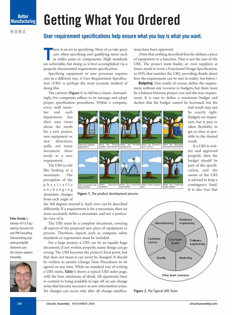
The cartoon (Figure 1) is old but a classic. Astound-ingly, few companies adhere to its message and adoptproper specification procedures. Within a company,every staff mem-ber and eachdepartment hastheir own viewsabout the needsfor a new project,new equipment ornew directions;sadly, not manydocument theseneeds as a userrequirement.
The URS is a bitlike looking at amountain. Theperception of thep h y s i c a l l yu n c h a n g i n gmountain changesfrom each angle ofthe 360 degrees around it. Each view can be describeddifferently. If a requirement is for a mountain, then wemust accurately define a mountain, and not a particu-lar view of it.
The URS must be a complete document, coveringall aspects of the proposed new piece of equipment orprocess. Therefore, aspects such as company safetystandards or ergonomics must be included.
For a large project, a URS can be an equally hugedocument; if not written properly, many things can gowrong. The URS becomes the project’s focal point, butthat does not mean it can never be changed. It shouldbe written to permit Change Note Procedures to beagreed on any time. While no standard way of writinga URS exists, Table 1 shows a typical URS index page,with the bare minimum of detail. All signatories haveto commit to being available to sign off on any changenotes that become necessary as new information arises.Yet changes can occur only after all change ramifica-
20 Circuits Assembly NOVEMBER 2006 circuitsassembly.com
Better Manufacturing
tions have been approved.(Note that nothing described thus far defines a piece
of equipment or a function. That is not the aim of theURS. The project team leader, or even suppliers attimes, needs to write a Functional Design Specification,or FDS, that matches the URS, providing details abouthow the requirement can be met in reality. See below.)
Budgeting. One could, of course, define the require-ment without any recourse to budgets, but there mustbe a balance between project cost and the true require-ment. It is easy to define a maximum budget anddeclare that the budget cannot be increased, but the
end result may notbe exactly right.Budgets are impor-tant, but it pays toallow flexibility toget as close as pos-sible to the desiredresult.
If a URS is writ-ten and approvedproperly, then thebudget should bepart of the specifi-cation, and theowner of the URSis advised to keep acontingency fund.It is also true that
Getting What You OrderedUser requirement specifications help ensure what you buy is what you want.
Peter Grundy is
director of P G Engi-
neering (Sussex) Ltd.
and ITM Consulting
(itmconsulting.org);
peter.grundy2@
btinternet.com.
His column appears
bimonthly.
How the customerexplained it
How the ProjectLeader understood it
How the Analystdesigned it
How the Program-mer wrote it
How the BusinessConsultant described it
How the project wasdocumented
What Operationsinstalled
How the Customerwas billed
How it was support-ed
What the Customerreally needed
Figure 1. The product development process.
Figure 2. The Typical URS Team

ARE 01005 PARTS ON YOUR ROADMAP?
THEN YOUR SMT LINES NEED CYBEROPTICS® AOI.
2000 2007
0603
0402
020101005
SE 300 Ultra™ Industry-leading 100% 3D solder paste inspection01005 solder paste height & volume with Gage R&R < 10%Optional MicroPad™ sensor inspects 100 x 100 micron padsNew easy-to-use Operator Interface and Defect ReviewEnhanced warp compensation for flexible circuitsWorld’s largest installed base of 3D SPI machines
Flex Ultra™ High speed pre- and post-reflow AOI01005 component offset measurement with Gage R&R < 10%Patented SAM™ vision technologySimple, low-maintenance mechanical architectureFast and easy programmingInspects any component or feature (gold fingers, connectors, etc.)Lowest false-calls in the industry
CyberOptics is a registered trademark of CyberOptics Corporation. SE 300 Ultra, Flex Ultra, MicroPad and SAM are trademarks of CyberOptics Corporation. © 2006 CyberOptics Corporation.
www.cyberoptics.com
Your best AOI choice for today. AND tomorrow.

22 Circuits Assembly NOVEMBER 2006 circuitsassembly.com
one or more suppliers may offer two solutions: one tofit the budget with possible repercussions on productquality or equipment life, and one to provide the idealmatch to the specification.
A number of sources provide evidence showing thatit does not pay to restrict the budget if the equipmentfunction and quality will suffer. A buyer may claim, “Iwant x result, but I can afford only y.” The supplier, ifsensible, may reply, “For y I can achieve 0.9x, and the
product will probably only just be capable of doing thejob.” The equipment may be ordered for y and willprobably just perform for the first few months, but thelikelihood is that it will be a weak design to fit the bud-get, and will soon require regular maintenance. Worse,it might fail altogether.
The teams. So, who should do this? Answer: Itdepends.
It depends on the project size, how long it mightrun, the number of departments it affects, and so on.Figure 2 shows a typical cross-discipline team. Thewider the disciplinary approach, the greater the possi-bility of covering all eventualities. This is not the onlyteam design, however. A one-person team can do thejob but will either take time or will miss somethingfundamental. Another alternative is to employ externalcontract help each time.
The FDS. The idea behind the URS is to specify whatthe customer wants to achieve without any bias. TheFDS should project the suppliers’ ideas about how tosolve the problem. In an ideal world, the FDS will con-tain few, if any, surprises but may contain novelapproaches. Even if you think you know the format anddesign of the equipment needed, it is always best towrite the URS as a description of what is needed ratherthan a description of how it might be achieved.
It could be that you may want to write the FDSyourself, but you must still apply discipline to use theprinciple of URS followed by FDS. It is usually easier tocompare FDSs from a number of suppliers and workout the optimum scope for your needs. If you rely on asingle supplier, risks such as insolvency, incompetenceor incompatibility should be considered.
When initially specifying something, you willachieve better results if you write a quality URS andthen match it to a sound FDS. You will then see howessential the URS/FDS connection is. ■
Better Manufacturing Topic Some Expanded Detail
History Describes the rationale and historical buildup to the project (why it was deemed necessary)
Acknowledgments Sources of information from outside the project team
Introduction Introduce the team players and their expected roles
Overview Define the expected scope of the project
Functions Define the detail of performance expectations
Nonfunctional Attributes Some of the equipment derived as part of the URS may have functions or features not
necessarily required by the project but could be useful in the future
Standards Define all known standards that apply to the equipment or process
Training Define for whom and for how long training will apply
Support Define the level of support available
Glossary Any “jargon” or specific terms that may need definition
Appendices Additional and supportive documentation
Signatories All those who have "bought into" the project or wanted it in the first place must be
prepared to sign for its acceptance at inception and again if there are any changes
Table 1. Typical URS Index Page
FREE WEBINARBusiness Outlook
A Global Electronics Industry:Updated for Q4 2006
Presented byUP Media Group and
leading market analyst Walt Custer
Co-sponsored byBare Board Group, Inc. and
DownStream Technologies, Inc.
AVAILABLE ON-DEMAND
Register today atwww.pcbshows.com/webinars

Procurement
Adata collection equipment manufacturernoticed that a technology shift was poisedto dramatically increase demand for a new
generation of product. Realizing that Asia wouldrepresent the lowest cost volume productionsource, the company shifted to a Chinese con-tract manufacturer. During peak demand, itsaved money. As volumes dropped off, the firmused its original U.S. EMS provider for end-of-life support.
A large companywith internal manufac-turing capability inMexico purchased anindustrial manufactur-er. The new parent'sstrategy was to transferoutsourced productionto its internal Mexicanand U.S. manufactur-ing operations. However, after the first year itfound that some of the product lines previouslyprofitable when outsourced in the U.S. wereactually costing more to build internally in Mex-ico. The solution was to reevaluate which prod-uct lines were outsourced vs. built internally.
EMS provider Genesis Electronics Manufac-turing has seen a number of its customers
choose to keep it as a supplier for niche prod-uct lines after situations such as these havedeveloped. Most OEMs have a mixed basket ofproduct, some of which transitions well off-shore, and some of which isn’t a good fit. Thatis why it may make sense to keep a small por-tion of the overall production requirementswith a domestic supplier. This potential mis-alignment with production business isn’talways obvious in the initial quoting process.For some OEMs, the understanding of totalcost isn’t completely evident until a project ismoved and the new production scenariorevealed to be a bad match, or a project scopechange occurs such as a demand drop in thelatter stages of a product’s lifecycle.
Conceptually, thisphenomenon can becategorized as a “price-berg,” where 80% of therisk may be hidingbelow the waterline instartup and ramp-down, where manage-ment costs per unitssold tend to be the high-est. Building a harmo-
nious, minimally disruptive dual-sourcing strate-gy requires an understanding of pricebergcomposition. The peak of the priceberg is the vis-ible high volume part, focused on for cost reduc-tion. Some projects have sharp peaks, while oth-ers are almost flat sheets of ice. Sharp-peakedprojects usually benefit from dual sourcing whilethe more predictable flat models may support a
Why U.S. production options may stillrepresent the lowest total cost for someprojects.
‘Re-Sourcing’ Outsourced Electronics Ed Grimes
24 Circuits Assembly NOVEMBER 2006 circuitsassembly.com
‘Sharp-peaked’ projects usually benefit from dual sourcing; flat models may support a single source.

Yeah. We’re Excited too.Let the Innov-X RoHS Engine Drive Your Compliance.• Get fast, accurate results on a
wide variety of samples• Detect PPM levels of Pb, Hg, Cd,
Cr and Br in seconds• Automatically classify mixed or
homogenous – alloy or polymer
Get More Orders, Not Recalls.• Screen non-destructively without disassembly• Confirm supplier MTR’s• Use field-proven screening methods• Focus laboratory testing costs• Don’t slow production
Try a Handheld XRF Free for a Day.Call: [781] 938-5005
[866] 4-innov-x
Email: [email protected]
Or, watch our Video Demos:www.innovxsys.com /rohs-demo
Ask about our rental programs:[email protected]
Innov-X Systems, Inc., Worldwide Headquarters, Woburn, MA USA.Innov-X Systems and the Innov-X Systems logo are trademarks ofInnov-X Systems, Inc. in the United States and all other countries.
All other marks are properties of their respective owners.©2006 Innov-X Systems, Inc. All rights reserved.
I n n o v a t i v e X R F Te c h n o l o g i e s
TM
Pb82
Hg80
Cd48
Br35
Cr24

Procurement
single source. Ultimately, sourcing strategy is best determined byevaluating what lies below the water line.
Hidden Cost DriversIn the first example, the OEM recognized that product devel-
opment and maturation had different support requirementsthan did the high-volume phase. The combination of fallingdemand, requirements for frequent engineering support andhigh product variation found in the development and matura-tion stages weren’t attractive offshore. This OEM recognized thatthe opportunity cost associated with slow responsiveness com-bined with internal overhead costs as a result of frequent stafftrips to the offshore source was greater than the cost associatedwith maintaining some level of U.S. production capacity. It has-n’t abandoned an offshore outsourcing strategy, but is using adual-sourcing strategy that mixes an onshore EMS provider forNPI activities and some production, and an offshore EMSprovider for product with higher annual quantities. The result isthat, while product has high ECO activity or is in a decliningproduction phase, the OEM receives optimum support from anEMS provider whose business model is aligned with that projectcomplexity, while a low-cost region handles products during thehighest volume phases.
In the second example, the project was also high mix, low vol-ume. Several assemblies had high PTH content and overall therewas little component commonality. Required labor content (ver-sus labor content driven by inability to automate board-levelassembly) was low, which meant that the added Customs admin-istration and logistics cost associated with migration to Mexicowasn’t completely offset by a lower labor cost. The result: Auto-mated board-level production in a U.S. EMS facility with astrong material procurement arm was less expensive than inter-nal production in Mexico for some product lines.
Likely Cost Drivers What project characteristics are likely to drive hidden costs
great enough to offset the perceived unit cost savings of offshoresourcing?
The most typical causes of misalignment with offshore high-volume production business models are:
• Variable market demand.• High mix/low volume production.• Low labor content.• Specialized inventory issues.• High ECO activity or need for configuration changes on the fly.• NPI support near the OEM’s engineering team.• End-of-life support/long product lifecycles.• Need for repair depot or other end market post-manufactur-
ing support activities.Evaluating an EMS provider’s track record with projects of
similar size and scope can be critical to understanding true busi-ness model alignment. When the business model is truly aligned,the EMS provider will not only be able to show similar projectson the floor, but will typically have systems in place for address-ing these common issues.
Areas of focus include:Corporate culture/business model. While this is more qualita-
tive than quantitative, it is often the largest driver of unantici-pated costs in variable volume, high mix or long lifecycle prod-uct lines. Offshore EMS models may have high minimumquantity commitments or require the building of small lotsonce or twice annually. From a tooling and product develop-ment standpoint, offshore ODMs may design in common partsthat go obsolete as the ODM changes its internal packaging orsubcomponent design. The client may not own tooling andrights to use the design. Low unit price may be offset with ECOor specialized support fees not originally quoted. The mostonerous cultural disconnect occurs when an EMS providerdecides to motivate bad-fit project attrition by increasing priceor dropping service levels.
The optimum way to analyze alignment with businessmodel is to ask the contractor to describe preferred projectcharacteristics. Most EMS providers can articulate the charac-teristics of an ideal project. If the characteristics describedalign with only a portion of the outsourced product, dualsourcing may be important. Checking references withaccounts of similar complexity, mix and volumes can also bean accurate way to gauge fit.
NPI/engineering support. A challenge for higher complexity orlonger lifecycle products isn’t necessarily the engineeringteam’s speed or depth of its “leading edge” expertise. Often it isthe ability to manage complex or high-mix product transi-tions, make component lifecycle recommendations, supportredesign because of obsolescence, and support a mix of old andnew technology during the product’s life. The ability to inte-grate design recommendations for manufacture or test into theinternal design process can also be critical as an optimizedautomation strategy reduces labor cost. Component choicesshould be aligned with an approved vendor list that enablesgoals for cost, availability and quality to be met over time.
26 Circuits Assembly NOVEMBER 2006 circuitsassembly.com
Figure 1. Long lifecycle, complex products often require extensive sup-port relative to end-of-life management, warranty and out-of-warrantyrepair and refurbishment. Here, technicians repair LCD assemblies.

circuitsassembly.com Circuits Assembly NOVEMBER 2006 27
Procurement
Tooling design and procurement exper-tise should also be evaluated carefully asthey impact tooling cost, part cost andultimately part quality. Another evalua-tion factor may be proximity to thedesign team or the willingness of thecontractor to support internal design orredesign effort with onsite engineers atcritical project review phases. A finalarea of focus may be willingness to sup-port strategic initiatives. For example,one of Genesis’ clients does not current-ly require RoHS-compliant product.However, in designing current product,the OEM has the company review eachBoM for component choices that willmigrate easily in an RoHS conversion.
Material/logistics management expertise.Higher mix, long lifecycle products oftenhave less component commonality and ahigher obsolescence risk. If demand isalso variable, excess inventory liabilityrisk is high. Key criteria to evaluateinclude ability to source hard-to-findparts; supplier agreements with liberalreturn privileges; channels for liquidatingexcess inventory; willingness to procureand store end-of-life buys, and ability tomanage variable demand with a cost-effective finished goods Kanban strategy.This is another area where an EMSprovider should be an extension of theOEM’s manufacturing organization.
Automation strategy/alignment of pro-duction capabilities. High mix, variabledemand product drives more frequentline changeovers. Often these productlines also include a mix of SMT andPTH technology. Reducing cost meansminimizing changeover time andautomating as much of the assembly andtest as possible. Key criteria to evaluateinclude equipment changeover flexibili-ty, availability of automated PTH inser-tion equipment, competency of testengineering personnel in developingcost-effective test strategies, breadth ofautomated test equipment, and overallinternal production strategy for manag-ing high mix production.
Ramp-down and post-manufacturingsupport. Long lifecycle, high mix, complexproducts often require extensive supportrelative to end-of-life management, war-ranty and out-of-warranty repair, and
refurbishment. A key issue is dealing withdeclining product demand. This mayrequire lifetime buys, redesign necessitat-ed by part obsolescence, and good sup-port in liquidating excess inventory.
Reverse logistics support can also beimportant. EMS providers that offer for-mal repair depot services typically under-stand the challenges associated with thisphase of product support. More impor-tant, when this is done as a distinct busi-ness focus, a shared infrastructure usuallyhelps offset the costs associated with end-market support, inventory managementand higher levels of troubleshooting tech-nical expertise. Access to reliable out-sourced repair depot support can alsocreate an additional value stream forOEMs by enabling the sale of service con-tracts to the end market. In addition,repair depot support can be used in a dualoffshore/onshore strategy by providing asafety net for product rework such asECO implementation for product in tran-sit as a new revision is cut in. Finally, out-sourced repair depot and reverse logisticssupport can help OEMs meet recyclingrequirements driven either by regulationsor market preferences.
As the priceberg analogy demon-strates, lowest unit price is rarely reflectiveof total project cost. Most EMS businessmodels have preferred classes of projects,and often the total basket of outsourcedproduct is not a perfect fit. OEMs takingthe one-size-fits-all approach may find80% of their management time is spentdealing with issues below the waterlineportion of their outsourced product. Tak-ing the time to evaluate varying require-ments in your product mix and develop-ing a dual-sourcing strategy that leveragesthe competencies of EMS providers withvarying business models is often the low-est cost approach. Most important, devel-oping this type of optimum sourcingstrategy on the front-end of an outsourc-ing project can save the cost and time of“re-sourcing” product that is out of align-ment at an offshore low bidder. ■
Ed Grimes is business development manager at
Genesis Electronics Manufacturing (genesismfg.com);

CustomerService
Field service representatives are like fire-fighters. When you need them, you needthem NOW. The urge for immediate help
often creates panic or even anger if the phoneisn’t picked up on the first ring. The ensuinginteraction can be tense, technical – and funny.
Those who provide technical support byphone know that only part of their job is techni-cal; the rest is psychological. A quick look at thefollowing humorous interactions can illustratethe path to more effective use of the technical ser-vice desk.
1. Key bits of data ease the situation. From anactual phone conversation:
Field service: Hello. How can I help you?Machine owner: Your machine doesn’t work.FS: Can you tell me the serial number of the
machine? MO: No. The number isn’t listed.FS: Do you know what model the machine is? MO: I can’t tell you. Can’t you get out my order
and look it up?FS: Well, what seems to be the problem with the
machine?MO: It’s creating scrap and costing a lot of
money. You need to fix it.FS: What is the name of your company and the
address?MO: I don’t have that information. I’m in New
Jersey and the machine is in China.
As this real-life example suggests, a littlepreparation could have saved time. To get theright help quickly, have vital information ready –perhaps even in writing – before you make thecall. This includes a model number, serial num-ber, type, model, age, and software in use. Howcan the problem be measured or how does itshow itself? Where does it occur (computerscreens, times, sequences)? What is the effect?Where is the machine located? Who are the nec-essary contacts, and what is their information? Isthe machine under warranty or a service contract,and what are the terms? What is the history of themachine? Is your company the original owner oris the equipment used or rented?
2. Know whom to call. We pick up the conversa-tion:
MO: Your stupid machine isn’t working again.FS: Sir, what machine do you have?MO: You know, YOUR machine!FS: We make several models, at least eight. Do
you know which model it is?MO: It is your machine! You would think you
could figure this out.FS: OK, what color is it?MO: It’s blue.FS: I’m sorry sir, that’s our competitor’s
machine.MO: Oh. (Pause) Do you have their phone
number?This actually happened. Ensuring you call the
right company, correct division and technical ser-vice department is not trivial. If you channel yourproblem into the best available resources, theproblem becomes much smaller.
Stories and suggestions for a happiercustomer.
What Your Field Service RepresentativeWants You to KnowFrank Murch
28 Circuits Assembly NOVEMBER 2006 circuitsassembly.com

CustomerService
circuitsassembly.com Circuits Assembly NOVEMBER 2006 29
You save time by finding the correct contact, usually the ser-vice person. In most companies a variety of people are willing tohelp: factory workers, sales staff and others. However, it is thefield service or technical support staff who are trained to reach asolution quickly and with the least disruption because theseissues are their focus.
3. Overlooking basic problems. We pick up the conversationmidstream:
MO: I cannot get your machine to work. I’m really upset aboutthis; your quality is low, and the thing won’t work. You are notgetting away with this.
FS: Well, let’s see what the problem is.MO: I already checked everything, and it is set up just like it
says to do it in the manual. I press the START button andnothing happens.
FS: OK, is it plugged in?MO: Of course, you think I would call about that? I did not call
to waste time with simple things. I think it is in the powersupply on the interface board.
FS: OK, is there a yellow light on the front panel?MO: Yes.FS: Please rotate the red E-STOP button on the right side. What
happens?MO: (Long silence, with machine noises in the background)
Ahhh, this is ridiculous; I will solve itmyself. (Click)
FS: (Into the dead line) I guess the Emer-gency stop button was pushed in.Variations of this conversation occur
daily. A large percentage of calls involvesomething obvious that was overlooked.We all do this, and it will happen to you.Check everything systematically; lookfirst for the simple solution. Often thesimplest answer is the right one. Is themachine plugged in? Is the power on? Areall the switches in the right place? Was theboot-up sequence followed? Are dials setcorrectly? Is everything in the correctposition? Are the fuses blown? Is a screwloose? What materials are you using? Arethe fuses the ones specified for yourequipment? Are parts old or worn? Areyou using replacement parts and materi-als specified by the manufacturer? (Sub-stituting non-recommended parts cancost time and money when the equipmentfails.) Does the problem occur in someplaces, but not others? What has changed?Are there trends in these data? What dataare available? What data are missing? Canyou make the problem come and go, ormanipulate it in any way?
List all possible root causes and thetesting required to confirm or reject each
cause. Can it be tested; if so, how? Try to identify the mechan-ical, software and electrical systems involved. Rate each as verylikely, possible and unlikely, and rank by number from cheap-est to most expensive. Start with the simplest, cheapest andmost likely, and then test your hypothesis. Analyze root causesby proving or dismissing each potential root cause. More thanone root cause is possible.
Use the checklist in the manual or from the field servicerepresentative to check all parts of the machine from top tobottom.
4. Explain all the details of the problem. MO: Our machine stopped working.FS: Can you tell me when and what happened?MO: It worked fine yesterday and this morning, but all of a
sudden it stopped.FS: Did you notice anything out of the ordinary when it
stopped?MO: Well, it could have something to do with the explosion
outside.This type of exchange occurs frequently (fortunately, without
the explosion). Something happens to the machine, and no onewants to admit his hands were on it when the problem occurred.However, service technicians generally find out anyway, as theyhave often made mistakes of their own. They are not looking to
You can’t go on ignoring it.There are voids in our life.
Go to microvoids.org
CKPW-0155 MV Teaser R1.ai 8/7/06 2:24:17 PM

CustomerService
place blame; they seek to define the problem and solution asquickly as possible. Being honest about the problem saves timeand directs the effort to what needs to be checked. You can helpby telling the technical support contact what happened. It isquicker, cheaper and usually the best way. Other examples we’veheard: “I dropped the machine”; “there was a flood”; “the thirdshift took a part to get another machine running”; “R&D recon-figured the machine for an experiment.”
5. Train the person who will be operating the equipment. A com-pany sends its best engineer for training. He arrives and stu-diously attends the classes and then plays golf for three days.Upon his return, he assigns the task to an untrained technician.The technician calls the equipment manufacturer, who trainshim, poorly, over the phone.
Variations of this occur. When trained and experienced oper-ators leave a company, funny things happen: strange computerprogramming, default values changed, odd configurations ofequipment. Training is key. It provides common terminologyand methods that form the basis for all diagnostic and setupwork. It is a way to create a uniform standard to solve problems(and avoid them). Want a smooth operation? Get training for theoperators. It is the cheapest and most effective tool available.
6. Read the manual. It’s amazing what can be learned aboutequipment in the accompanying manual. If there’s something
you don’t understand, ask before a problem occurs. If the manu-al is poorly written, let the company know.
7. Use the field service representative’s time to your best advan-tage. Maximize time spent on your equipment by uncrating themachine and plugging it in. The less time technicians performbasic handling, the more time they can spend demonstratinghow to operate and troubleshoot the equipment.
8. When field service representatives arrive, let them help you.They are trained and willing to help. They understand you havemade an investment in capital equipment, and they want you tosucceed.
We all have the same goal: to get that equipment working.Follow these steps and 90% of your problems will disappear. Andwhen this does not produce a solution, you will be prepared tocall in the experts. Maybe you’ll even have time to laugh about itlater. ■
Frank Murch is director of field service at Asymtek (asymtek.com);
30 Circuits Assembly NOVEMBER 2006 circuitsassembly.com
In the electronics manufacturing services industry, differentiation is key to
winning accounts. Differentiation isn't simply the best slogan or ad, it's also
the approach taken in developing value propositions, setting expectations
and delivering promised value after the sale.
Powell-Mucha Consulting, Inc. offers a variety of consulting services, and
onsite and online training programs to support team focus on efficient account
acquisition and long-term customer growth. Our focus is not simply on
training your sales force, but on creating support for the customer acquisition
process throughout your organization. The end result is a total team focus
where sales effort is concentrated on "ready-to-buy" accounts and operations
personnel are fully informed of opportunities and potential account issues
during the selling process.
As opportunities increase, your organization stays focused because the
customer acquisition cycle has become a defined and measurable process
instead of a series of activities which become more chaotic as the number of
potential opportunities and sales team members increase.
Request a copy of our article reprint:“EMS Differentiation Through Branding,”by calling 915-585-7285 or visiting:www.powell-muchaconsulting.com.

Special Advertising SectionAssembly Insider
circuitsassembly.com Circuits Assembly NOVEMBER 2006 31
Equipment Classifiedspowered by
CIRCUITS ASSEMBLY’S
new online marketplace
provides access to thousands
of classified listings containing
used PCB assembly equipment,
used SMT equipment and used
semiconductor equipment.
circuitsassembly.kitmondo.com
Your best choicefor quality PCBs
www.efabpcb.comIf you have any questions
or need assistanceCall Toll Free 1-877-332-2722or Contact - sales@efabpcb
Check out our low pricesand save big $
Our Proto-Power Pack Specialswill save you even more!
Easy to use instant on-line quoting
Quality PCBs at competitive prices!Free tooling on Proto-types
Lead-free andRoHS finishes available
Efabpcb is a UL approved and QS-9000 certified facility

PCBDesign Trends
The process of designing a printed circuitboard is key to the overall product lifecycle.This process not only impacts product
development, it influences the speed and successwith which a company is able to bring products tomarket. Here are an EMS provider’s insights intothe stages of PCB layout – a key phase in thedesign process.
During design layout, an EMS provider gath-ers necessary input from the customer, includingschematics, mechanicals and other critical infor-mation, and leverages its experience with a cross-section of product types to lay out the board andconduct the necessary reviews. Once the cus-tomer has approved the board layout, the EMSprovider outputs a set of files that are either lever-aged by the OEM in the fabrication, test andassembly of PCBs, or by the EMS provider if ithas been engaged for turnkey services.
The level of outsourcing engagement greatlyinfluences the activities, people and stagesinvolved in layout. In recent years, OEMs havebegun outsourcing activities traditionally han-dled in-house. These activities range from fullturnkey solutions – through which EMSproviders act as an extension of the OEMthroughout the design, manufacture and test of aproduct – to outsourcing a single aspect of theproduct lifecycle, such as PC layout, sometimes inconjunction with other engineering services.
OEMs’ engineering teams need to engage inPC layout well in advance of circuit design. TheOEM may not yet know if there is enough realestate to fit all the necessary components on theboard and if it will meet certain criteria such asdesign for excellence (DfX), test points and signalintegrity. This early supplier involvement hasbecome typical of outsourced PC layout duringthe past three years. (And EMS providers wel-come this shift, as the earlier they are engaged, themore value they can provide to the customer.)
It is crucial for EMS providers to have anestablished, proven set of global guidelines andprocesses for PCB layout. These can be internal,such as corporate guidelines, or external, such asISO certifications that many customers require.These processes ensure the same method is usedfor each design layout, and that the output pro-vided meets customer expectations. Regardless ofOEM input, the output is verified in the samemanner.
Celestica’s PCB layout team follows estab-lished ISO 9001:2000 procedures, and is alsorequired to follow an internal corporate designguide that outlines standards and guidelines for:
• Design for manufacturability (DfM).• Design for fabrication (DfF).• Design for test (DfT).• Sourcing.• Manufacturing/assembly.
Manufacturing and test guidelines should alsobe taken into consideration during layout (Figure1). While many established customers plan theirlevel of outsourcing engagement in advance, oth-ers do not plan early enough. In such instances,
The key components include corporatestandards and OEM-EMS collaboration.
Understanding Outsourced PCB LayoutPaul Barsley
32 Circuits Assembly NOVEMBER 2006 circuitsassembly.com

PCBDesign Trends
circuitsassembly.com Circuits Assembly NOVEMBER 2006 33
unless customer-specific guidelines are provided, Celestica lever-ages its own manufacturing guidelines. OEMs that eventuallyoutsource the assembly find this “turnkey” mindset beneficial.
Stages of Circuit LayoutOnce the OEM’s engineering team has developed a product
concept, the physical aspects of the product must be determined(Figure 2).
The OEM must decide on the product’s functionality, howmany circuit boards will be required, the physical “envelope” ofthe product, packaging size, etc. OEM engineers then design thecircuit board schematics and mechanical drawings and definethe types of components to be used. It is important to note that,as the industry further embraces outsourcing, it is becomingcommonplace for the customer to develop the product conceptand then engage an EMS provider for the remainder of the prod-uct’s lifecycle.
Before commencing with layout, a team must be establishedto manage the process. At Celestica, once a project is defined, ateam is quickly established. A program manager, whose respon-sibilities include monitoring the scope of the project and ensur-ing that customer requirements are met, leads the team. The restof the team includes electrical and mechanical engineering,DfM, DfT, physical layout design and components procurement.This comprises the minimum team that should be assigned tonew product development; depending on the complexity of theproject and customer requirements, the program manager mayadd additional members.
A formal face-to-face kick-off meeting is often the first step ofthe layout process. This meeting allows all technical and businessauthorities involved in the project to interact, and should be heldwith all first-time design customers, for complex projects, andfor design projects involving other departments or suppliers. Adesign engineer typically represents the OEM customer. Theteam may also choose to invite representatives from external par-ties such as PCB fabricators, high-volume printed circuit assem-bly or testing houses, or EMI testing facilities. The meeting pro-vides a forum to discuss customers’ and outside vendors’requirements, expected design results, project timeline andschedules and the end product. This discussion, along with cus-tomer input, leads to the development of the design plan.
The next stage should involve obtaining the basic projectinput requirements or a statement of work from the customer.This may include:
• Board outline drawings.• Component specifications.• Design technologies to be used.• Netlists and critical netlists.• Suggested placement drawing.• Fixed component location drawings.• Logic diagrams.• Wiring diagrams.• Schematics.• Test specifications.• Renderings.
• Mechanical drawings.• Samples and any other supporting material.
This input is evaluated to determine if it will produce theexpected design results and output documentation.
The output is further defined when the design task is outlinedmore precisely and the customer exposed to other availabledeliverables. Design output packages may include:
• Bills of material (BoM).• Assembly or fabrication drawings.• Schematics.• Wiring, timing or block diagrams.• Gerber photoplot files.• Aperture lists.• N/C drill files or drill bit lists.• Back-annotation files.• Component X-Y placement files.• Valor ODB++ database.• Netlists in various formats.• Signal integrity reports.• Test procedures.• Approved vendor lists (AVL).• Approved manufacturer lists.• PCB databases.• Film packages.
If the customer requests additional output, the design planmust be adjusted accordingly.
The EMS provider’s PCB layout group then develops CADlibrary symbols for each component the customer identifies,determines the physical board size, and generates a netlist basedon the board schematics that itemize components and theirpoint-to-point connections. This is a collaborative phase, asOEM and EMS electrical and mechanical engineers work to flagrestrictions and other potential issues. In these early stages, theboard layout team is in daily contact with engineers.
The board layout team then determines the placement of crit-ical components on the board. Critical components includehigh-speed parts and those that are sensitive to other compo-nents and must be placed and routed in a certain way. Depend-
Figure 1. Design process overview.

PCBDesign Trends
ing on the level of engagement, at this stage, signal integrityanalysis services can be leveraged to save the customer time andmoney. This upfront analysis results in fewer revisions and buildsfor each layout and is quickly becoming a “must” given the com-plexity of today’s designs. One might say that design analysis is tothe electrical design engineer what “spell-check” is to PC users –once they use it, they can’t live without it.
Our OEM customers use design analysis extensively, arequirement on all new board developments internal to Celesti-ca. This technology can contribute to the layout process, includ-ing the schematics phase, in several areas. This technology per-mits Celestica to determine the outcome of the customer’s board
34 Circuits Assembly NOVEMBER 2006 circuitsassembly.com
schematic. The ability to manage the complexity of designs andgeneral design constraints is critical, as companies cannot affordmultiple design revisions to resolve issues that could have beenresolved before the first release build.
The next stage of PCB layout is design verification: providingboth parties with visibility into the progress and direction of theproject. Verification activities vary, depending on customerrequirements (defined in the design plan) and the EMSprovider’s level of engagement. In-process design reviews areheld and approved at milestones specified during the kickoffmeeting or in the design plan. All approving authorities receivedata in the form of files, plots and reports, which permit them todo in-process checking at specified points.
While the layout is in process, it is sent to various peoplewithin the EMS provider for review so that issues can be flagged.Reports are then sent to the customer to review verification per-formance. Design verification can be conducted through the useof one or more of:
• Paper check plots.• System-generated reports.• On-screen reviews.• Database checking tools.• System-specific checking tools.
Following design verification is design validation. As the cir-cuit’s owner, the OEM engineer is the only party capable ofdetermining whether the original intent of the electrical circuitperforms to specifications. The customer’s ability to validate isenhanced by the use of on-screen software applications andreports that show the expected results of the layout techniques asthey are used. If design changes are required, the customer mustapprove them prior to incorporation. An appropriate procedureand form should be used to document all design changes, ensur-ing their incorporation and disposition. The customer must benotified of the impact of each proposed change with regard toschedule and cost and must approve or withdraw the changerequest.
Following several review cycles and OEM approvals, the EMSdesigner prepares all of the documentation requested in thedesign plan. At this stage, the EMS provider may conduct a finalanalysis to see if all customer requirements have been met. Thedesign release enables the next stage of product development totake place (i.e., fabrication and assembly).
It is extremely important that OEMs partner with EMSproviders possessing the experience, skill set and best practicesneeded to optimize this phase of product development, sheddinglight on potential issues and enabling the customer to overcomeany barriers to success. ■
Acknowledgments
The author thanks Debbie Lam and Dennis Compeau of Celestica for their help in
preparing this article.
Paul Barsley is vice president, global design services at Celestica (celestica.com);
Figure 2. Printed circuit layout process flow.

CoverStory
Acquisition integration is a challenge forany company. The EMS industry posesspecific challenges because customers
aren’t buying an end-product; they are buying thecapabilities, systems, processes and internal cul-ture used to manufacture their product.
In pursuing its acquisition strategy, EMSprovider EPIC Technologies has tried to maintaina balance between achieving business growthgoals and customer satisfaction. This focus hasincluded:
• An evaluation during due diligence ofacquired facilities and their customers’ affinitytoward EPIC Technologies’ value proposition.
• A management process for operational analy-sis after acquisition.
• A strategy for standardizing corporate culturein newly acquired operations.
• A formal customer expectation analysis andsatisfaction measurement process.EPIC began expanding beyond its first manu-
facturing facility in Norwalk, OH, in early 2002with the establishment of a greenfield site inJuarez, Mexico. The company completed thefacility launch within 60 days, after completelyrenovating a vacant 70,000 sq. ft. facility,installing more than 80 machines, hiring andtraining more than 120 employees and providingfirst-article submissions on approximately 25products. In December 2004, the company
expanded its Juarez manufacturing capability,while adding a significant customer by acquiringan OEM’s 125,000 sq. ft. electronics assemblyoperation in Juarez. In January 2005, EPIC alsoacquired the assets and business of Siemens Ener-gy and Automation’s EMC division. This acquisi-tion added new capacity in two locations: SouthLebanon, OH, and Johnson City, TN.
Due diligence. When an EMS acquisition failsto add to the bottom line, the problem is typical-ly either failure to achieve the operationalimprovements projected in initial valuationassumptions or customer attrition.
How can this be countered? EPIC Technolo-gies’ model relies on operational standardizationand a tightly focused value proposition tied to thecompany’s Synchronous Flow Manufacturing(SFM) process. In evaluating potential acquisi-tion candidates, the focus includes some corestrategic questions:
• Does the operation add needed geographicreach or additional capabilities?
• What challenges would be present in adaptingacquired operations to the standardized SFMprocess?
• Does the customer base appear to value theLean manufacturing philosophy, and is theproduct mix appropriate for this focus?In the two acquisitions described, the answer
was yes. The Juarez acquisition added a customerthat valued Lean principles and a facility in aregion that had strong demand. The SiemensEMC acquisition added new customers as well asadditional projects from an existing customer.The facility had already had some focus on imple-
Implementation must be fast, withquantitative measures of performance.
Maintaining Customer SatisfactionDuring EMS Acquisition IntegrationTodd Baggett
36 Circuits Assembly NOVEMBER 2006 circuitsassembly.com

Continued on pg. 39
CoverStory
circuitsassembly.com Circuits Assembly NOVEMBER 2006 37
mentation of Lean principles and also added new capabilities inengineering and failure analysis.
Operational analysis. Fully implemented, the company’s SFMphilosophy incorporates the following basic concepts:
• Align processes with customer needs.• Team with suppliers to optimize supply chain practices.• Appropriately size raw material kanbans to align with likely
customer needs.• Team with customers to optimize finished goods transfer
methods.• Minimize waste.• Minimize travel time of inputs, WIP and finished goods.• Eliminate excess WIP or finished goods through smaller lot
sizes.• Eliminate underutilized equipment by standardizing process-
es, minimizing changeover time and“right sizing” production capability.
• Empower employees.• Standardize operating procedures
across the organization and cross-trainemployees in multiple jobs.
• Use visible production status indica-tors to provide real-time indicators ofoperational efficiency.
• Have operators control factory sched-uling based on visibility into currentneeds.
• Measure results.• Use standard reviews to measure a
consistent range of efficiency metricsin all facilities.
• Have a continuous improvement pro-gram that looks at reducing total costand includes a focus on both measur-able costs and opportunity costs dri-ven by inefficiencies.Standardization is key in both operat-
ing strategy and fast acquisition integra-tion. EPIC has a standard facility layoutthat uses the same equipment andprocesses in every factory. As facilities areacquired, layout is evaluated against the standard formula, andexcess equipment is either redeployed to other facilities or liqui-dated. Equipment not found in the facility, such as vapor phasereflow ovens and custom wave solder machines that have beenoptimized to support broader process windows, are added. Forexample, in the Johnson City facility, the analysis process deter-mined that the current facility output could be handled on twoSMT lines. Four other lines were redeployed to other facilitiesand the remaining lines modified to support the standardprocess flow.
Early in operational strategy formulation, managementdeveloped a methodology for measuring and sharing perfor-mance information known as the Plant Operating Review (POR)system. The original version monitored approximately 60 met-
rics company-wide down to the floor level. These metrics wereformally reviewed daily and weekly by project personnel, month-ly by the plant managers, and quarterly by senior management.This system formed the foundation for continuing operationalanalysis. Following the Siemens EMC acquisition, the POR sys-tem was modified based on suggestions from the acquired team.The revised system uses the original metrics list and measure-ment frequency and now also considers external benchmarksand longer-term performance trends. The current review processstarts with a summary of overall company financial performancemetrics, and then focuses on specific productivity and opera-tional performance in the following functional areas: humanresources, quality, manufacturing, sales, purchasing and finance.The functional managers responsible for performance to mea-sured metrics are also responsible for defining the external
benchmarks relevant to their areas.Review frequency is consistent with thetiming established in the original system.
Corporate culture integration. Visionsharing starts the day the deal closes.There is open communication betweencompany management and the acquiredteam. While there is a clear direction forchange established, existing processes andnew ideas from the acquired team areevaluated. If a new concept represents animprovement, it is incorporated in themodel companywide.
The best driver of integration of cor-porate cultures is a formula of centralizedtraining combined with standardized jobdescriptions. Just as the operational strat-egy focuses on increased flexibilitythrough equipment standardization, thestrategy for operator cross-trainingfocuses on creating a flexible workforcethat could be deployed to areas of the fac-tory in rapid response to customerdemand. There is organizational consis-tency in job descriptions, training topicsand processes, and workforce deployment
strategies in all facilities; this information is easily accessiblethrough a company intranet system. For the most part, employ-ees who are industry certified or “EPIC-Certified” through train-the-trainer processes conduct training.
Customer satisfaction measurement. Customer satisfactionmeasurement primarily exists in two forms. At least one key con-tact at each customer fills out a monthly scorecard via the Inter-net measuring standard metrics such as quality, on-time deliveryand pricing/cost reduction performance. A more detailed annu-al survey conducted via email measures:
• Overall performance satisfaction at EPIC compared to satis-faction with the customer’s other EMS providers.
• Perception of management and key support competencies.• Relationship with project team.
Figure 1. Placement equipment is standardizedacross all facilities.
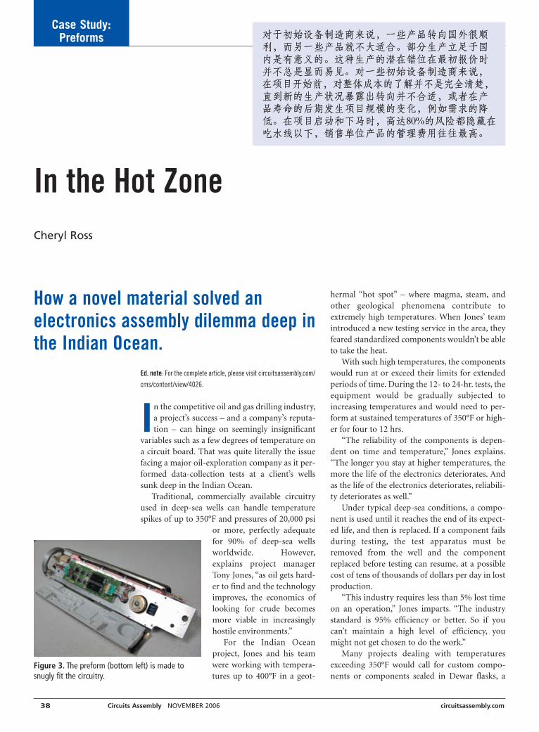
Case Study:Preforms
Ed. note: For the complete article, please visit circuitsassembly.com/
cms/content/view/4026.
In the competitive oil and gas drilling industry,a project’s success – and a company’s reputa-tion – can hinge on seemingly insignificant
variables such as a few degrees of temperature ona circuit board. That was quite literally the issuefacing a major oil-exploration company as it per-formed data-collection tests at a client’s wellssunk deep in the Indian Ocean.
Traditional, commercially available circuitryused in deep-sea wells can handle temperaturespikes of up to 350°F and pressures of 20,000 psi
or more, perfectly adequatefor 90% of deep-sea wellsworldwide. However,explains project managerTony Jones, “as oil gets hard-er to find and the technologyimproves, the economics oflooking for crude becomesmore viable in increasinglyhostile environments.”
For the Indian Oceanproject, Jones and his teamwere working with tempera-tures up to 400°F in a geot-
hermal “hot spot” – where magma, steam, andother geological phenomena contribute toextremely high temperatures. When Jones’ teamintroduced a new testing service in the area, theyfeared standardized components wouldn’t be ableto take the heat.
With such high temperatures, the componentswould run at or exceed their limits for extendedperiods of time. During the 12- to 24-hr. tests, theequipment would be gradually subjected toincreasing temperatures and would need to per-form at sustained temperatures of 350°F or high-er for four to 12 hrs.
“The reliability of the components is depen-dent on time and temperature,” Jones explains.“The longer you stay at higher temperatures, themore the life of the electronics deteriorates. Andas the life of the electronics deteriorates, reliabili-ty deteriorates as well.”
Under typical deep-sea conditions, a compo-nent is used until it reaches the end of its expect-ed life, and then is replaced. If a component failsduring testing, the test apparatus must beremoved from the well and the componentreplaced before testing can resume, at a possiblecost of tens of thousands of dollars per day in lostproduction.
“This industry requires less than 5% lost timeon an operation,” Jones imparts. “The industrystandard is 95% efficiency or better. So if youcan’t maintain a high level of efficiency, youmight not get chosen to do the work.”
Many projects dealing with temperaturesexceeding 350°F would call for custom compo-nents or components sealed in Dewar flasks, a
How a novel material solved an electronics assembly dilemma deep inthe Indian Ocean.
In the Hot ZoneCheryl Ross
38 Circuits Assembly NOVEMBER 2006 circuitsassembly.com
Figure 3. The preform (bottom left) is made tosnugly fit the circuitry.

Continued from pg. 37
Case Study:Preforms
circuitsassembly.com Circuits Assembly NOVEMBER 2006 39
• Responsiveness to problems.• Perception of price competitiveness.• Plans for future business allocation.
This annual survey is sent to multiple contacts at each cus-tomer and includes areas for detailed comments and suggestionsfor improvement. Survey data are reviewed at the plant and cor-porate level. Program managers are charged with developing cor-rective action plans related to customer improvement commentsor areas that rate low in any survey.
Maintaining the highest levels of customer satisfaction duringacquisition does not occur without a learning curve. For exam-ple, customers that haven’t embraced Lean manufacturing likethe added scheduling flexibility, but may be slow to adopt rec-ommended changes related to forecasting methodologies orapproved vendor list. Program managers often must drive thisconversion a step at a time.
Quantitative improvements. To understand the overall effective-ness of the strategy, it is helpful to look at some of the measuredmetrics. Quantitative improvements at the company’s mostrecent acquisition have included:
• Elimination of customers’ obligations for firm schedules withpulls / “ship on demand” while improving on-time delivery ofcustomer requests from 74% to 87% (the goal is 98% asachieved in other EPIC facilities).
• Reduction in revenue associated with past-due orders of 90%,to $300,000 from $3 million.
• Reduction in production square footage of 43%, including
transfer or elimination of four production lines while sup-porting the same amount of revenue.It is also significant to note that during its period of greatest
growth in 2005, it also achieved record levels of third-partyrecognition. Awards measuring customer satisfaction presentedin 2006 for performance measured during the prior year include:
• Three CIRCUITS ASSEMBLY 2005 Service Excellence Awards. EPICwon three of five categories in the medium-sized EMS com-pany segment including: Technology, Dependability/TimelyDelivery and Responsiveness based on third-party customerinterview scores.
• Siemens Medical Solutions USA Inc. 2005 Supplier of theYear. This award was presented to the company’s JohnsonCity facility based on cumulative supplier scorecard resultsthroughout 2005.Customer affinity for the new business model will always play
a role. This necessitates a focus on customer base expectationsduring due diligence. The EMS provider will likely have to “sell”its expectations for forecasting and preferred supply base to itscustomers as changes are implemented.
The rewards of both sides taking the time to assess expecta-tions and team to achieve critical goals are improved operationalperformance, increased schedule flexibility, and both visible andhidden cost-reduction. ■
Todd Baggett is vice president of business development at EPIC Technologies
(epictech.com); [email protected].
kind of protective sleeve. But Jones was happy with the func-tionality of the components on hand – provided they could finda way to shield the circuitry from the worst temperature spikes.
Because of the depths at which the components would beused, they had to be enclosed in a special housing to protectthem from the pressure. But the sealed housing acted like anoven, baking the circuits inside. The pressure housing precludedcooling apparatus, such as fans.
An overheated component can stop working for a while andthen resume working when temperatures cool – or it can diealtogether. To avoid both scenarios meant finding a way to keepthe components safely under the 350°F threshold.
Avoiding a RedesignWithout a suitable solution, the team would be faced with
redesigning the chassis to better dissipate the heat. They wouldalso have to redesign the circuit boards to convey the heat to thechassis instead of to the atmospheric cavity or the external pres-sure housing. The in-depth redesigns would have added timeand expense that neither Jones nor the client wanted.
Another alternative Jones considered was for his team to potor encapsulate the components using commercially availablematerials. “While that solution might have worked,” Jones indi-cates, “it’s a time-consuming, labor-intensive operation thatrequires a lot of processes to ensure consistency.”
Jones began searching for possible solutions, eventually con-
tacting Dow, which brought in Ultimate Solutions (ultimateso-lutions-inc.com). Ultimate Solutions makes a patent-pendingtechnology called preforms, a highly filled silicone material thatprotects electronics components from shock, vibration and tem-perature extremes.
Please see the rest of this article online.
Figure 7. Component temperatures monitored during field-testingfound that components with preforms cycled 50° to 59°F hotter thanthe temperature of the sealed pressure housing, or 18° to 27°F lessthan components without preforms.

40 Circuits Assembly NOVEMBER 2006 circuitsassembly.com
TechTips
from these gases will remove both organic and inor-ganic contaminates. Measure the effectiveness ofplasma cleaning by placing a drop of DI water on thebond surface and visually examining the contactangle of the water drop. A high contact angle indi-cates surface contamination. A low contact angle,where the water drop spreads over the bond surface,indicates a clean surface.
Tip 3. The product must be held rigidly. If theproduct moves during wire bonding, ultrasonicenergy is lost and the bond will not form complete-ly. Check the work holder, or confirm the tool isclamping the part firmly before the wire bondingoperation starts. The clamping should be repeatable.You may have to put a time delay in the program to
permit the clampedpart to settle beforestarting the wire bond-ing process.
Tip 4. Check for con-sistent and symmetri-cal free-air balls. Thediameter should beapproximately 1.5times the wire diame-ter (Figure 1).
Tip 5. Adjust theultrasonics, force andtime. Change parame-ters individually, aschanging all the para-meters at once willmake it impossible todetermine which
change has the most impact on improving the wirebond.
Tip 6. Replace the wire bond tool with a differentlot number of the same tool, or use an equivalenttool from a different supplier.
Tip 7. Replace the wire with a different lot numberfrom the same supplier, or use an equivalent wirefrom a different supplier.
Tip 8. Finally, check the equipment calibration, thebond head mechanisms and the operation of themachine.
With good controls on incoming materials,dependable wire bond process control checks, andregular equipment maintenance and calibration, thewire bonding operation will run defects of less than100 ppm. ■
Troubleshooting Wire BondingEight ways to lower defect rates below 100 ppm.
With so many variables, troubleshooting wirebond programs can be tricky. These tipswill make the process a bit easier.
Tip 1. Confirm the wire bonder’s setup is correct.1. Install a new wire bonding tool and set screw. If
not available, make sure the old bonding tool isthe correct part number for the wire size beingbonded. Under a microscope, at 10X minimum,inspect the tool and set screw to see if it is wornor dirty. Reinstall the tool and seat the set screwto the manufacturer recommended setting with atorque wrench. Test the ultrasonics; if the ultra-sonics are tuned and working properly, proceedwith the setup.
2. Install a new spool of wire. If new wire is notavailable, confirmthe wire in the oldspool is the correctsize and alloy com-position. Make surethe wire is not dirty,damaged orspooled incorrectly.Verify the wirefeeds smoothlythrough to thebond tool.
3. Load the securedcopy of the wirebond program intothe wire bonder.Always keep a copyof the wire bondprogram in a securearea away from the production floor. You can eas-ily reinstall the program if the production copybecomes corrupt.
4. Using a calibrated thermometer, verify the heat-ed stage is the correct temperature. A thermoson-ic process, gold wire bonding typically requiresthe product be heated to 150˚C.
5. Using a setup sample, evaluate the program forrepeatability and resulting bond strengths.Tip 2. Bond surfaces must be clean, smooth and
contaminant-free. Use cleaning solvents to flush con-taminates from bond surfaces. Plasma cleaning willremove micro-contaminates but in most cases willnot remove debris or other macro-contaminates.Oxygen plasma will remove organic contaminates.However, removing inorganic oxides requires argongas or a mix of argon and oxygen gas. The plasma
The American Compet-
itiveness Institute
(aciusa.org) is a sci-
entific research corpo-
ration dedicated to the
advancement of elec-
tronics manufacturing
processes and materi-
als for the Department
of Defense and indus-
try. This column
appears monthly.
Figure 1. Free-air ball (courtesy Small Precision Tools Inc.)

Pan Paci f ic
Spon
sore
dby
ww
w.s
mta
.org
952-
920-
7682
smta
@sm
ta.o
rg
Pan Paci f ic
SM
TA
Surf
ace
Mou
ntTe
chno
logy
Ass
ocia
tion
30 January - 1 February, 2007 | Maui, Hawaii International Technical Interchange
The Pan Pacific Symposium focuses on the critical business markets and technologies ofmicroelectronic packaging, interconnection, microsystems technology and assembly.
The Pan Pacific Tabletop Exhibition puts you in contact with global key decision makersand provides access and international visibility for your company and products.
12th Annual
MicroelectronicsSymposium &
TabletopExhibition
MicroelectronicsSymposium &
TabletopExhibition

Solder is an alloy mix consisting of two or moremetals. Melting and solidification behavior ismuch dependent on the formation of areas in
the solder where different eutectics might solidify. Thiscan be the case if solder contains elements such as cop-per and silver. In such a case, CuSn and AgSn eutecticparts or traces can form next to the SnAgCu eutecticduring the solidification of the solder in the joint.
As molten solder solidifies, it shrinks approximately4%. Most of this volume reduction can be found inareas where the solder solidifies last. These are typical-ly areas where traces of the lowest melting eutectic sol-der are found. If these traces are at the joint surfacearea, this mechanism can create a dull appearance. The4% volume reduction can often also be held responsi-ble for the formation of micro-cracks in the solderjoint.
During solidification, the eutectic with the lowestmelting point is often surrounded by already solidifiedparticles from the eutectics with the higher meltingpoints. This means that during final solidification ofthe solder joint, a “soup” forms of molten solder andsolidified particles that have a different grain structurethan the last solidifying alloy elements. During thissolidification process, the solder volume shrinks by theaforementioned approximate 4%, with the main partof this volume reduction and contraction to be foundon those alloy parts in the joint that solidify last. Thismix of liquids and solids solidifying at different stages,each with a dissimilar surface structure, combined withvolume reduction, finally gives the joint a dull appear-ance.
Shrink Structure FormationWhen the solder alloy contains elements that can
form more than one eutectic alloy, different shrinkagepatterns can be formed that will give the solder joints arough appearance. Since the cooling of a soldered jointafter leaving the wave is affected by many factors – sol-der volume in the joint, the heat sinking effect of theparts involved, alloy composition, lead plating, and soon – the solder solidification will not be the same for alljoints. This means that joints can have a differentappearance at the end of the soldering process. Here’swhy:
Assume that a given SAC solder volume has theexact ternary eutectic composition Sn3.5Ag0.9Cu. Thisalloy will have a melting point of 217°C. In fact, under
42 Circuits Assembly NOVEMBER 2006 circuitsassembly.com
WaveSoldering
ideal conditions, it has only that melting point and noother melting points from the binary eutectics that alsocould be present in this solder volume. So, this volumeof solder will solidify as one homogeneous alloy in fullequilibrium because of its exact ternary eutectic com-position and equal temperature. Normally, such analloy would solidify with a smooth surface under theseconditions, since the solder shrinkage is equally divid-ed over the volume.
Next, assume that extra tin is deliberately added tothis perfect ternary solder mixture. The extra tin can-not be part of the ternary eutectic because the alloynow contains too much tin. This “excess” tin, having amelting point of 232°C, will first precipitate as solidi-fied crystals (dendrites) as the solder cools, until theremaining liquid mix has its perfect ternary eutecticcomposition. As this remaining liquid mix continues tosolidify at 217°C, the solder shrinks by about 4%. Thisshrinkage originates with the remaining liquid and notfrom the already solidified tin dendrites. The finalshrinkage will take place at the point where the joint atlast reaches a temperature below 217°C. In most casesthis is the part in contact with the solder wave for thelongest time, typically the joint fillet at the solder side.Thus, the tin dendrite profile is primarily present at thesurface of the solidified solder.
In real solder joints, the ideal ternary mix (assumingone begins with such an alloy) is mixed with metallicparts from the PCB and lead metalization. Parts ofthese elements dissolve into the limited amount of sol-der that forms the joint. These extra elements now dis-turb the ideal ternary eutectic. This means that thesolidification of that solder mix is not at a commontemperature of 217°C, but that parts of this mix maysolidify at 232°, 227° or 221°C. In the event that thecomponent leads are SnPb-plated, SnPb eutectic tracesor SnPbAg eutectic traces with melting points of 183°Cand 178°C, respectively, may also be found in the joint.In most cases, SAC alloys are used with a compositionthat deviates from the ideal eutectic composition. Thismight create the different eutectics that ultimately gen-erate a rough joint surface. ■
The Role of Eutectics in SolderJoint AppearanceA mix of liquids and solids solidifying at different stages gives joints a dull look.
Gerjan Diepstratenis a senior process
engineer with
Vitronics Soltec BV
(vitronics-soltec.com);
gdiepstraten@nl.
vitronics-soltec.com.
This column appears
monthly.

circuitsassembly.com Circuits Assembly NOVEMBER 2006 43
Test andInspection
average gray level value is measured representingsolder presence. The average gray level is then com-pared to a model average gray level previously deter-mined by the user. This results in calculating a per-centage to represent how close the measured solderjoint is to the known nominal average value. A pin isindicated when the calculated percentage is less thana set threshold. For example, anything lower than90% of the nominal average gray level will be indi-cated as insufficient.
Using this technique,an automatic test can beset up to inspect severalregions within the barreland on the board sur-face. Figure 1 shows anx-ray laminographicimage taken at 75% bar-rel (right side) and animage taken at the bot-tom of the board (leftside). The system deter-mines the missing solder
and joint for pin 49. For pin 51, a joint is present, butthe solder did not flow properly up the barrel, creat-ing an insufficient joint. The system measured at75% barrel fill that pin 51 is within 84% and pin 49is within 30% of a known satisfactory solder joint’saverage gray value. For both of these joints, a presentend fillet can be identified. Depending on the manu-facturing requirements, this automated test could bearranged to catch missing and inadequate solder fill,or just the missing joint, by adjusting the allowablepercent of the measured nominal average. ■
Bibliography
IPC-A-610D, Acceptability of Electronic Assemblies, February 2005.
Stig Oresjo, “Test and Inspection as Part of the Lead-Free Manufacturing
Process,” ECWC 10 Conference, IPC Apex Proceedings, February 2005.
Dr. David Bernard and Bob Willis, “Measurement Variation in PIHR Pb-Free
Solder Joints,” “Using X-Ray Inspection, the Efficacy of Pin-In-Hole
Reflow with Different Board Finishes is Studied,” SMTA International
Proceedings, September 2005.
PTH Solder Joint InspectionAutomated x-ray laminography ensures through-hole joints meet barrel fill specs.
Although plated through-hole package produc-tion is a mature process, it still results in unre-liable and poor quality solder joints. IPC-A-
610 specifies that an acceptable criterion forthrough-hole solder joints is that at least 75% of thebarrel is filled along the board thickness and that abottom fillet is present. Various testing technologiesexist to ensure a sound electrical connection is creat-ed, but automated x-ray laminography is the onlyavailable technology that can ensure the through-hole solder joint meetsthe IPC-A-610 specifica-tions of barrel fill.
The widely usedtechnique of wave sol-dering the bottom sideof a board produces aneffective solder jointwith a strong bottom fil-let. At times, however,solder will not flowproperly, falling short ofthe required 75% of thebarrel. This occurs if a pin is bent, contaminated oran insufficient amount of solder paste is deposited.This is also common when using Pb-free solder for-mulations, as the lower wetting force of Pb-free sol-der decreases the ability for solder to fill the hole suf-ficiently.
The “paste-in-hole” soldering technique (alsoknown as “pin-in-paste”) is a relatively new processof simultaneously printing solder paste for bothSMT and through-hole packages. This technique isused when dealing with a double-sided SMT assem-bly in which components sensitive to high tempera-tures are used on both sides. This technique also mayleave an undesirable solder fill because of poor wet-ting, insufficient amount of solder paste and no bot-tom fillet.
Electrical tests may be used to ensure that a con-nection is made from the joint to the board. Onsome packages with visible joints, visual inspectionconfirms that solder appears to have flowed throughthe barrel. X-ray laminography is the only testingmethodology permitting measurements to be madewithin the barrel to ensure the solder fill within thejoint meets the required IPC specifications.
X-ray laminography inspects specific regions or“slices” along the barrel and tests for solder presence.For each “slice” taken, a region of interest is createdaround the barrel. Within this region of interest, an
Jeremy Jessen is tech-
nical marketing engi-
neer at Agilent Tech-
nologies (agilent.com);
jeremy_r_jessen@
agilent.com.
Figure 1. This image shows how x-ray laminographyreveals missing solder and insufficient joints on platedthrough-hole leads.

Investigating Dendritic Growth Getting to the root of capacitor shorts.
extracted solution. By using a Y electrode with a 0.050"pitch and a 10V bias, the electrical impact of the cont-aminants in the DI water can be assessed and a solutiondetermined. DI water can consistently cause copperdendrites to short in 450 to 500 sec., while corrosiveionic residues cause shorts much faster. (For example,9.2 µg/in2 of chloride has constantly caused shorts in19 sec.).
Table 1 (online) shows ion chromatography analysisof the C3 extraction sites. The area of the corrosion siteshows a high level of weak organic acids (WOA) onlyon the component next to the selective solder area.Using the current production assembly for processcomparison, it also shows a high level of WOA only onthis location. Each area tested shows a low chloride,bromide, nitrate and WOA, except the area next to theselective wave. Bare-board cleanliness appears to be lowfrom the HASL cleaning process, and because thecapacitor from the same vendor’s reel nearby (but notnext to) the selective wave also showed low levels ofionic residue, it was not a result of these contributors.
The root cause of this failure is the presence ofwater-based no-clean flux trapped below the confor-mal coating covering the surface of the capacitor. Thisflux when not completely heat-activated has a pH of2.5 and is very corrosive, enough for dendrite growthbelow a coating. For the biased circuit with sufficientcorrosive flux (not completely heat-activated), this fail-ure mechanism caused a dendrite to grow across thesurface of the capacitor. ■
Arecent failure analysis presented with a clear fail-ure mechanism of a dendrite shorting along thesurface of the component. Our job was to deter-
mine what happened.A simple dendrite grew across the surface of a 3V
capacitor (Figure 1), but curiously it grew below thecoating and did not break the surface. No visible con-densing water was present on this field failure, whichwas used as a controller assembly in a controlled envi-ronment for 30 days. No other components showedvisible residue issues on the component surface.
Process conditions. The acrylic coating thickness wasuniformly 0.003" to 0.004" thick over the board surface.The mixed technology assembly included bottom-sideSMT and selective soldering. A low-residue, no-cleanapproach was used to build the assembly. The bottom-side SMT parts were reflowed with a no-clean solderpaste, while through-hole components were solderedwith a VOC-free, no-clean flux. A selective pallet pro-tected SMT components from the solder wave.
Analysis techniques. Analysis was conducted using x-ray fluorescence and ion chromatography using a local-ized extraction tool: the C3 tester. XRF showed tin andlead metalization through the coating only. Scrapingsamples viewed with XRF also showed tin and leadmetalization in the dendrite.
Ion chromatography analysis of the entire assemblywould not reveal what caused the localized corrosioncell on one capacitor. Thus, a focused extraction wasconducted by first using a scalpel to roll back the con-formal coating and C3 to isolate an extraction area of0.1 in2. The C3 tester uses DI water steam to solublizeanything that would come into solution under normaloperating conditions as an extraction solution, andthen conducts an electrical impact assessment of the
44 Circuits Assembly NOVEMBER 2006 circuitsassembly.com
ProcessDoctor
Terry Munson is
with Foresite Inc.
(residues.com);
tm_foresite@
residues.com. His
column appears
monthly.
Figure 1. This dendrite on the surface of a 3V capacitor caused shorts in the field.

circuitsassembly.com Circuits Assembly NOVEMBER 2006 45
EquipmentAdvances
INOKIT software uses a “one package/one location”approach to minimize machine setup, teardown andreloading. It increases SMT machine utilization accuracyand reduces unplanned material shortages by improvinginventory accuracy. Users can run a specific MRP sce-nario based on specified criteria: across all customers ora single customer; across multiple kit selections or a sin-
gle kit. The customer decides whichtime frames and time buckets to view,and “what if” scenarios are based onthe BoM. By generating kit statuseson-the-fly, users can determine mini-mum builds and understand excessinventory, material shortages, inven-tory on hand and RoHS compliance.
The INOSOURCE procurementprogram pools the corporate purchas-ing activities of several electronicsmanufacturers into a large aggregatethat enables greater purchasing powerwhile reducing procurement laborcosts. All procurement needs are com-bined under a single umbrella, in
accordance with participants’AVLs. It can be used to pro-cure an entire line or manufactured items. It permitsaccess to a network of offshore manufacturers and sup-pliers. IT can also validate the BoM cost of the customer’scurrent product, and negotiate cost reductions on apiece-part basis.
The equipment and software are available fromInovaxe, inovaxe.com. ■
Inovaxe’s Inventory Control Tools
Inovaxe’s supply-chain management and inventorycontrol tools consist of three related products: theINOCART handling system, INOKIT kitting soft-
ware and INOSOURCE procurement program. Theycombine business intelligence software with materialhandling equipment to bridge gaps in traditionalMRP/accounting software.
INOCART and INOKIT, for kit-ting and reloading SMT lines, is amaterial handling solution that per-mits numerous package types to bestored in a secure, controlled manner,whether on reels, tubes, feeders orPCBs. The cart and software are saidto improve inventory accuracy. Eachindividual package is given a uniquebar-coded location, which is the basisfor managing inventory and kittingfunctions.
INOCART is a mobile bondedstockroom that can be movedthroughout the plant. It eliminates theneed for caged, bonded stockroomsand permits inventory storage wherever material is actu-ally needed. It comes in sizes of one, two and three bayswide, and has a maximum storage capacity of 1,296packages. It can accept material directly from on thedock, eliminating labor and movement to other stock-rooms after receipt. It can be used on the line, permittingmaterial to be loaded directly to the SMT line, eliminat-ing job kitting and staging.
INOCART is a bonded stockroom onwheels.
NEED GERBER DATA?www.pcbscanning.com
mil certified

Handset DeviceProgrammer
FlashCORE family of manual and automatedprogramming solutions has been adapted andoptimized to program mDOC H3 devices at veryhigh speeds. Enables mass adoption of mDOCH3 in mobile handsets and consumer electron-ics devices. mDOC H3 is the first multi-sourceembedded flash drive specifically designed formobile handsets and consumer electronics.Data I/O, dataio.com
Rapid Cooling ProcessAccelerated cooling process uses flip-chip-in-
package nonconductive paste underfill to heatdevices while secured by the flip-chip bonderhead, then rapidly cools them during compres-sion onto the NCP-coated substrate. Enablesassembly completion prior to any excess heatexposure, reducing package warpage, voidscaused by moisture and assembly cycle time.Said to cut cycle time including IC alignment to7 sec.Henkel, henkelelectronics.com
High-Speed FlexibleMounter
KE-2080 high-speed flexible mounter has sixnozzles with laser alignment and an additionalIC head for fine-pitch components. IPC-9850speed is reportedly 15,400 cph. Handlesdevices from 01005 to 33.5 mm sq. LNC60laser align sensor, which includes laser-center-ing placement capability for most 1.27 mmpitch BGAs and an optional placement loadcontrol, measures six parts simultaneously. Stepmotors control input and output buffer convey-ors, enhancing speed. Data, feeders, nozzlesand floor trolleys are interchangeable withother Juki lines. Comes standard with an axescontrol system that increases the number ofmotors on the pick-and-place head butdecreases the cables.Juki Corp., jas-smt.com
Pallet RotatorThe PalletPal Rotator can be used to rotate
fully loaded pallets, replace broken pallets, andswitch to or from in-house/shipping pallets,transfer loads to slip sheets, and replace dam-aged goods at the bottom of a load without theneed for manual restacking. Handles loads upto 48 x 48 x 60" with capacities up to 4400 lbs.Loads rotate a full 180° on a massive anti-fric-tion turret bearing and can be stopped at anypoint during rotation.Southworth Products, southworthprod-ucts.com
ProductSPOTLIGHT
46 Circuits Assembly NOVEMBER 2006 circuitsassembly.com
DfM-Supporting PLM ToolVShare product lifecycle management toolset supports DfM col-
laboration between PCB design and engineering by means of acentralized, scalable platform that offers secure access to importantdesign information and DfM issues. The tool’s dashboard is said tocapture all relevant DfM data in a centralized environment so thatall users can work in real-time with the same, graphically rich dataset. Runs using standard Internet browsers within a secure, Web-based environment. Can import DfM results from other selectedtools and attach graphical or text objects. Generates reports on crit-ical steps, project status and details, and approvals.Valor Computerized Systems, valor.com
Auto-Vision Alignment Batch PrinterSemiTouch batch stencil printer is a semiautomatic stencil/screen
printer with full auto-vision alignment. Has a maximum print areaof 16 x 20", and handles stencil frame up to 29 x 29" and boardsizes from 2 x 2" to 16 x 23" with servo-controlled, fully program-mable x, y and theta automatic vision alignment. Vibraserve fea-tures run-time diagnostics, message feedback and advanced safe-ty features; options include closed-loop squeegee pressure control,ultrasonic bottom-side stencil wiping system, and choice of Grid-Lok, Red E Set or other support tooling.Milara Inc., milarasmt.com
Label Printer and Attachment The ELC-200 Label Print and Attach system applies labels on
PCBs or end-products, and can print barcode and 1- and 2-D ontoPCBs. PC-operated controls, with an extruded aluminum framewith painted vanity panels and a transparent cover. Standard fea-tures include handling PCBs from 50 x 50 to 330 x 250 mm, three-color light tower lamp with audible alarm, conformance toSMEMA standard 1.2, mechanical front stopper and clamper. Hasa reported maximum fixed conveyor speed of 200 mm/sec., and amaximum processing speed average of 8 sec./label.Eunil H.A. Americas Inc., eunilam.com
ESD-Safe Bar Code Imager Quadrus MINI ESD Safe miniature fixed-mount imager can be
integrated into ESD-sensitive assembly processes. Reads codes onsensitive components without discharging static. Nickel coatingand ESD-resistant labels permit integration without aerosol coat-ing or restrictive mounting distances. Has a megapixel sensor forreading long bar codes and high-density 2-D symbols in anydirection on multiple surfaces.Microscan, microscan.com

EQUIPMENT FOR SALE
K3 Equipment Co. LLC279 Front StreetBinghamton, NY 13905PH: 607-773-2047FX: 607-773-0956www: k3equipment.comE-mail: [email protected]
Thru Hole Assembly- Universal 6287 Axial Inserter
- Universal 2596 Sequencer
- Contact Systems CS400D
Surface Mount- GSM Spare Parts
- Camalot XYFlex
- Quad IVC
- Quad QSP-2
- Quad QSV-1Plus
- Mydata TP9-UFP
Soldering & Cleaning- Electrovert Econopak I
- Heller 1700S Oven
- Dover Soltec 6522C Wave
- Vitronics Isotherm Reflow
- Vitronics SMR 800 Oven
CLA
SSIF
IED
SCL
ASS
IFIE
DS
CLA
SSIF
IED
S
Device Programmerwith Tray Input
Helix desktop automated device program-
mer now comes standard with two preci-
sion-designed tray input and output han-
dling systems with a reject location, capable
of the same dph performance. Tray version
uses the same core programming technolo-
gy and socket modules as standard auto-
mated lines. Pressure plates are exchange-
able between the two units. Integrated in
the handler are two Enhanced 7th Genera-
tion programming sites with FX4 socket
module capability, which permits program-
ming of up to four devices simultaneously
per site. Handles such packages as MSOP,
SOIC, PLCC, SSOP and TSSOP.
BPM Microsystems, bpmmicro.com
1. Publication Title: CIRCUITS ASSEMBLY
2. Publication No.: 1054-0407
3. Filing Date: 9/25/2006
4. Issue Frequency: Monthly
5. No. of Issues Published Annually: 12
6. Annual Subscription Price: $80.00
7. Complete Mailing Address of Known Office of Publication: UPMedia Group Inc. - 2400 Lake Park Drive - Suite 440 - Smyrna,GA 30080; Contact Person: Jennifer Schuler; Telephone: 918-496-1476
8. Complete Mailing Address of Headquarters or General Busi-ness Office of Publisher (Not printer): 2400 Lake Park Drive -Suite 440 - Smyrna, GA 30080
9. Full Names and Complete Mailing addresses of Publisher, Edi-tor, and Managing Editor: Publisher, Pete Waddell - 2400 LakePark Drive - Suite 440 - Smyrna, GA 30080; Editor, Mike Bue-tow - 2400 Lake Park Drive - Suite 440 - Smyrna, GA 30080;Managing Editor, Javier Longoria - 2400 Lake Park Drive -Suite 440 - Smyrna, GA 30080
10. Owner: UP Media Group, Inc., 2400 Lake Park Drive - Suite 440- Smyrna, GA 30080
11. Known Bondholders, Mortgagees, and Other Security HoldersOwning or Holding 1 Percent or More of Total Amount of Bonds,Mortgages, or Other Securities: None
12. Does not apply
13. Publication Name: CIRCUITS ASSEMBLY
14. Issue Date for Circulation Data Below: September 1, 2006
15. Extent and Nature of Circulation:
Average No. copies Each Issue During Preceding 12 Months;No. Copies of Single Issue Published Nearest to Filing date
a. Total Number of Copies (Net Press Run): 46,675; 43,785
b. Paid and/or Requested Circulation:
(1) Paid/Requested Outside-County Mail Subscriptions Stat-
ed on Form 3541 (Include advertiser’s proof andexchange copies): 23,047; 24,214
(2) Paid In-County Subscriptions Stated on Form 3541(Include advertiser’s proof and exchange copies): 0; 0
(3) Sales Through Dealers and Carriers, Street Vendors andCounter Sales and Other Non-USPS Paid Distribution:22,522; 17,594
(4) Other Classes Mailed Through the USPS: 0; 0
c. Total paid and/or Requested Circulation (Sum of 15b (1), (2),(3), and (4)): 45,569; 41,808
d. Free Distribution by Mail (Samples, complimentary, andother free):
(1) Outside-County as Stated on Form 3541: 0; 0
(2) In-County as Stated on Form 3541: 0; 0
(3) Other Classes Mailed Through the USPS: 0; 0
e. Free Distribution Outside the mail (Carriers and othermeans): 653; 1,700
f. Total Free Distribution (Sum of 15d and 15e): 653; 1,700
g. Total Distribution (Sum of 15c and 15f): 46,222; 43,508
h. Copies not Distributed: 453; 277
i. Total (Sum of 15g, and h.): 46,675; 43,785
j. Percent Paid and/or Requested Circulation (15c. Divided by15g times 100): 98.58725282; 96.09267261
16. Publication of Statement of Ownership: Publication required.Will be printed in the November 2006 issue of this publication.
17. Signature and Title of Editor, Publisher, Business Manager, orOwner: I certify that all information furnished on this form istrue and complete. I understand that anyone who furnishesfalse or misleading information on this form or who omitsmaterial or information requested on the form may be subjectto criminal sanctions (including fines and imprisonment) and/orcivil sanctions (including multiple damages and civil penalties).(signed) Pete Waddell, September 17, 2006.
United States Postal Service Statement of Ownership, Management, and Circulation
ProductSPOTLIGHT
Lead Removal KitsLead Eliminator, Lead Test Kit and Lead Remediation Kits find
and remove lead and other heavy metals from workbenches andmanufacturing areas, tools, machinery and a variety of surfaces.Come separately or as part of a kit.JNJ Industries Inc., jnj-industries.com
Selective Soldering PreheaterPH4 preheater has an IR radiation area of 300 x 300 mm, is a
standalone unit and can be used with any SSM 4A selective sol-dering or SSM 9 desoldering stations. Reduces copper separationon PCBs by means of shorter contact time with solder. Power con-sumption of 3500W, which can preheat thick PCBs.Zevac AG, zevac.ch
circuitsassembly.com Circuits Assembly NOVEMBER 2006 47

48 Circuits Assembly NOVEMBER 2006 circuitsassembly.com
Cleaning“A New Environmentally Benign Method for
Lead-Free Solder Defluxing”Authors: Albert J. Mastrangelo, Susan
Chute, Jay Soma, Robert Sell and ChristineFouts
Abstract: Recent testing of multiplecleaning technologies has indicated that theco-solvent degreasing process is capable ofcleaning these new fluxing systems. Inaddition to being an effective cleaningprocess, the co-solvent technology is bothenvironmentally friendly and cost effective.This study examines the effectiveness of theco-solvent process using a variety of clean-ing chemistry types and a large number ofboth lead-free and lead alloy eutectic solderpaste formulations from multiple leadingsuppliers. (SMTAI, September 2006)
Reliability“Reliability of Copper Wire Bonding in Plas-
tic Packages at High Temperature (200˚C) andHigh Current”
Author: Michael HundtAbstract: Operating temperatures of
plastic packages for automotive uses mustincrease up to 200°C and perform withhigh current. This is critical for plasticpackages because storage at high tempera-ture causes wire-bonding degradation.When gold wire is used, AuAl intermetallicsgrowth occurs, leading to high increase ofelectrical resistance and possible ball lift.This work characterizes reliability of cop-per-wire bonding in plastic packages at200˚C with high current, and compares theresults with those of gold wire. It also com-pares failure mechanisms. A non-bromineresin was used to avoid intermetallics cor-rosion. Although the CuAl intermetallicsgrowth was found to be slower, the CuAljoint can prematurely lose its mechanicalintegrity because of the high brittleness ofthe intermetallics. (SMTA Harsh Environ-ments Workshop, July 2006)
“Tertiary Amine Corrosion of Copper Elec-trical Contacts in an Automotive Environment”
Authors: Tim G. Basner, Henry (Hank)M. Sanftleben and Mary B. Young
Abstract: Continuously open electricalcontacts resulted in an automotive systemfailure. A corrosion product caused electri-cal failure of the contact. The corrosion was
observed on copper components in closeproximity to a urethane foam. Corrosionresidue analysis determined that an amine-copper ligand or complex was formed. Ahighly accelerated laboratory test (“bag-gie”) was developed to reproduce systemfield failures, identify key and required cor-rosion factors and screen alternative mate-rials. Various materials were evaluated toprovide a corrosion-free contact. Correc-tive actions studied were to bake the aminesout of the foam before assembling; use dif-ferent foams/amines in the foams; orchange the metals exposed to the foam.(SMTA Harsh Environments Workshop,July 2006)
Packaging“Flip Chip Integration of a Large Format
Array of MOEMs Devices for Space InfraredAstronomy”
Authors: Christine A. Allen, John Abra-hams, Nick Costen, Larry Hess, Mary Li,Timothy Miller, S. Harvey Moseley, JamesPontius, David Puckett, Eric Schulte andChristian Zincke
Abstract: A large format micro-opto-electro-mechanical systems (MOEMS)array known as the Microshutter Array(MSA). The completed MSA chip has elec-trical connections on the top and bottomof the chip to enable 2-D addressing of thearray. Electrical and mechanical connec-tion of the MSA device chip to the sub-strate containing the address circuitry isaccomplished through a combination ofroom temperature single-sided indiumbump bonding and conventional wirebonding processes. Traditional eutectic ballbonding is unsuitable because of tempera-ture constraints on the fully fabricatedMSA devices. Underfilled gold stud com-pression bonding has been applied, butresults in undesirable issues such as punch-through shorting, lower than optimalinterconnect yield, and warping of compo-nents upon cool down to the operatingtemperature. Indium bump bonding hasproven an excellent solution for establish-ing highly reliable electrical and mechani-cal interconnects without the need forunderfill. This paper presents design con-siderations, process overview, and testresults, including launch simulation vibra-tion testing. (SMTAI, September 2006)
Bare Board Group, www.bareboard.com . . . . . . . . . . . . . . . . . . . 31
BEST, Inc., www.solder.net . . . . . . . . . . . . . . . . . . . . . . . . . . . . . . 9
BPM Microsystems, www.bpmicro.com . . . . . . . . . . . . . . . . . . . . 19
Christopher Associates, www.christopherweb.com . . . . . . . . . . . 13
CyberOptics, www.cyberoptics.com . . . . . . . . . . . . . . . . . . . . . . 21
Data I/O Corporation, www.dataio.com . . . . . . . . . . . . . . . . . . . 11
Digi-Key, www.digikey.com . . . . . . . . . . . . . . . . . . . . . . . . . . . . C2
Dynatech Technology, Inc., www.dynatechsmt.com. . . . . . . . . . C3
eFabPCB, www.efabpcb.com . . . . . . . . . . . . . . . . . . . . . . . . . . . 31
Grid-Lok, www.grid-lok.com . . . . . . . . . . . . . . . . . . . . . . . . . . . C4
I&J Fisnar, www.ijfisnar.com . . . . . . . . . . . . . . . . . . . . . . . . . . . 17
Indium Corporation of America, www.indium.com . . . . . . . . . . . 5
Innov-X Systems, www.innov-xsys.com. . . . . . . . . . . . . . . . . . . . 25
Interplex Industries, www.interplexnas.com . . . . . . . . . . . . . . . . 15
JNJ Industries, www.jnj-industries.com . . . . . . . . . . . . . . . . . . . . 3
K3 Equipment, www.k3equipment.com. . . . . . . . . . . . . . . . . . . . 47
KIC, www.kicthermal.com . . . . . . . . . . . . . . . . . . . . . . . . . . . . . 23
Liconix Industries, Inc., www.liconix-usa.com . . . . . . . . . . . . . . . 31
Pan Pacific Symposium, www.smta.org . . . . . . . . . . . . . . . . . . . 41
PCB West 2007, www.pcbwest.com . . . . . . . . . . . . . . . . . . . . . . 35
Powell Mucha Consulting, . . . . . . . . . . . . . . . . . . . . . . . . . . . . . 30www.powell-muchaconsulting.com
Precision Images, www.pcbscanning.com . . . . . . . . . . . . . . . . . 45
Precision Placement Machines, Inc., www.goppm.com . . . . . . . . 31
Seika Machinery, www.seikausa.com . . . . . . . . . . . . . . . . . . . . . 27
Siemens Logistics & Assembly Systems, Inc., . . . . . . . . . . . . . . 2www.siplace.com
Sierra Proto Express, www.protoexpress.com . . . . . . . . . . . . . . 31
Specialty Coating Systems, www.scscoatings.com . . . . . . . . . . . . 3
Speedline Technologies, www.speedlinetech.com . . . . . . . . . . . . 7
Used Equipment Classifieds . . . . . . . . . . . . . . . . . . . . . . . . . . . 31circuitsassembly.kitmondo.com
Walt Custer Webinar, www.pcbshows.com/webinars . . . . . . . . . . 22
Ad IndexADVERTISER INFO: To learn about the advertisers inthis issue, go to circuitsassembly.com and select“Advertiser Index” in the gray horizontal menu bar at thetop of the page. This will provide you with direct links tothe home or product pages of each advertiser in thisindex.
Company Page No.
Advertising SalesNorth UP Media Group, Inc.
America: 2400 Lake Park Drive, Suite 440Smyrna, GA 30080
Group Sales Director:Susan Jones, (404) 822-8900email: [email protected]
Sales Associate:Kamden Robb, (678) 589-8843email: [email protected]
Asia: Jan Vardaman, TechSearch InternationalInc., 512-372-8887email: [email protected]
Korea: Young Media, 82 2 756 4819email: [email protected]
TechnicalAbstracts In Case You Missed It

SAMSUNG SM Series!
The Dawn of a New EraSAMSUNG SM Series!
The Dawn of a New EraPlace more components with the SM Series from Samsung.
Extend the variety of components you can place with the SM Series from Samsung.
Boost performance with more feeders on the SM Series from Samsung.
Expand your production range with the SM Series from Samsung.
Get started on your new era. Contact us today.
Need more?Speed • Flexibility • Components • Feeders
Get more!See the new complete SAMSUNG Production Line
Outside North America
SAMSUNG TECHWIN CORP., LTD.SMT Global Sales & Marketing Dept.Semiconductor System Division333-1, Sangdaewon-dong, Jungwon-gu, Seongnam-si, Gyeonggi-do, Korea 462-120P: +82.31.730.8725 F:+82.31.730.8797www.Samsung-SMT.com
Outside North America
SAMSUNG TECHWIN CORP., LTD.SMT Global Sales & Marketing Dept.Semiconductor System Division333-1, Sangdaewon-dong, Jungwon-gu, Seongnam-si, Gyeonggi-do, Korea 462-120P: +82.31.730.8725 F:+82.31.730.8797www.Samsung-SMT.com
Dynatech Technology, Inc.
Exclusive North American distributor of SMT assembly solutions by Dynatech Technology, Inc. • 103 Rock Road • Horsham PA 19044P:215.675.3566 • F:215.675.4259 • [email protected] www.DynatechSMT.com