Circuit to convert tumbler switch to momentary switch …web.tiscali.it/pahler/DYI cockpit controls...
96
DIY cockpit controls How to build your own flightsim cockpit controls Version 1.0 Roland van Roy March 2002 DIY cockpit controls © Roland van Roy 2002 1
-
Upload
trinhthuan -
Category
Documents
-
view
217 -
download
0
Transcript of Circuit to convert tumbler switch to momentary switch …web.tiscali.it/pahler/DYI cockpit controls...

DIY cockpit controls
How to build your own flightsim cockpit controls
Version 1.0 Roland van Roy March 2002
DIY cockpit controls © Roland van Roy 2002 1

Contents1. Introduction................................................................................................................................................................32. DISCLAIMER..............................................................................................................................................................43. How to start?...............................................................................................................................................................54. What Tools do you need.............................................................................................................................................65. Basic electrical information.......................................................................................................................................7
Connecting switches PC keyboards..............................................................................................................................7Connecting relays to keyboards....................................................................................................................................8Connecting Opto-couplers (photo-couplers) to keyboards........................................................................................9Circuit to convert toggle switch action to momentary switch action using relays.................................................10Toggle switch action to momentary switch action using Opto couplers..................................................................11Combination key-strokes.............................................................................................................................................12Making your own joystick connections to PC game port.........................................................................................13Unstable (jittery) controls............................................................................................................................................16Joystick switches and POV HAT................................................................................................................................17Connecting multiple joysticks to your PC..................................................................................................................18Connecting external potmeters to a USB joystick (joystick hacking).....................................................................19Potmeter wiring issues.................................................................................................................................................20Making connections......................................................................................................................................................21
6. Cockpit console layout.............................................................................................................................................22Yoke function keys.......................................................................................................................................................22Cockpit console dimensions.........................................................................................................................................23Flightsimming setup.....................................................................................................................................................24
7. Cockpit controls description (Flight yoke).............................................................................................................25Home build flight yoke for flight simulation..............................................................................................................25Description of cockpit controls (other parts).............................................................................................................30Gear lever......................................................................................................................................................................30Gear up / down indicator.............................................................................................................................................30Parking brake...............................................................................................................................................................33Speed brake...................................................................................................................................................................33Flaps lever.....................................................................................................................................................................34Throttle, Prop-pitch and Mixture controls................................................................................................................35Rudder pedals...............................................................................................................................................................36Rudder and Elevator trim wheels...............................................................................................................................38
Rotary encoder to keyboard stroke interface circuit for rudder and elevator trim.....................................................40Limitations of keyboard when driving with pulsed switches.....................................................................................41
8. Adding Tactile Transducers to your sim setup......................................................................................................44Basic construction of home made transducer............................................................................................................45Transducer amplifier circuits......................................................................................................................................46Note on building subwoofers for light aircraft simulation sound system:..............................................................49
9. Overview of complete cockpit switch wiring diagram..........................................................................................50Other wiring connection details..................................................................................................................................51
10. Complete cockpit console pictures......................................................................................................................53Cockpit artwork............................................................................................................................................................54
11. Some notes on using the cockpit controls during the flightsim........................................................................5412. Material price indications....................................................................................................................................5513. Sources for information.......................................................................................................................................5614. Attachment:...........................................................................................................................................................57
Text of joykeys.cfg and flt3.cfg....................................................................................................................................57Cockpit artwork............................................................................................................................................................58
DIY cockpit controls © Roland van Roy 2002 2

1. Introduction
PC flight simulator programs are getting better and better. Realistic flight models together with excellent cockpit instrument graphics and satellite photo-realistic scenery makes PC flight simulation a great hobby. The interface for controlling the various cockpit controls leaves something to be desired. Using a standard joystick and keyboard is not very realistic. Making controls feel more like the real cockpit controls adds a lot to the total flightsim experience.
There are lots of commercial cockpit control setups available, but things can become quite expensive if more functionality is desired. There are some very professional flightsimmers around who have build complete cockpits of specific aircraft, with full functional instrument panels, controls, multi-displays, etc. But in general, those great setups require deep pockets.
Since I do most of my flightsimming (mostly VFR) in various types of light aircraft, I decided to build a simple generic light aircraft cockpit controls console, with the flight yoke and various levers and switches at the places that are most common for those aircraft. All components come from local hardware and electronics shops (lots of those in here in Taiwan) and stuff that I got at the local (household) junkyard.With a little imagination, some basic wood- /metal-working and electronics skills, and the help of the great info sites on the net, you can build a nice cockpit setup for very little money. Just for indication: I estimate my complete setup (w/o PC and monitor) has cost me about USD$200,- (Based on Taiwan street prices, see the section “Material price indications”).
I have written this document for those flightsimmers who want to add something simple to increase the realism of their setup. My setup can be applied to basically any PC based flightsim program, since I used only standard interfacing methods. (keyboard, game port and USB joystick).For my flightsimming, I use Flight Unlimited III . It’s a couple of years old, but still a great program. Therefore, you’ll find many references in the text to the keyboard functionality of this program. However, I don’t see any reason why the same principles could not be applied to Microsoft Flight Simulator or other simulator programs with only some minor modifications.
This document contains the full description of all parts (both electrical and mechanical), and some of the basic tricks and tips concerning components, PC keyboards and game ports you need to know in order to make things work with your PC. Except where I listed the source, the mechanics and circuits are my own design, but since they are rather straightforward, it is very well possible that somebody else thought of the same things earlier. In this case, please excuse for not giving credit, as I was not aware of it.
In some cases, you may find my designs somewhat crude. I have tried to keep things as simple as possible, while maintaining reasonable functionality. Since I don’t know much about PC peripherals specifications, many circuit solutions are based experiments, not specs. Things work with my setup, but I cannot guarantee that they will work with other setups. (A rather poor engineering practice, but hey, this is hobby, not work).
The Flight Unlimited III community at AVsim has a group of very active and dedicated people making great freeware add-on aircraft and scenery, improving the sim continuously. This document is my contribution to the flightsim community, and I hope it will be of help for getting more enjoyment out of your sim experience.
DIY cockpit controls © Roland van Roy 2002 3

2. DISCLAIMER
USING THE METHODS / CIRCUITS / COMPONENTS AS DESCRIBED IN THIS DOCUMENT IS ENTIRELY AT YOUR OWN RISK. IF YOU DAMAGE YOUR PC / JOYSTICK / KEYBOARD / YOURSELF BY ANY OF THE THINGS I WROTE DOWN IN THIS DOCUMENT, IT’S NOT MY FAULT.
Having said that, here are some tips to limit the damage:
1. Switch of the power and UNPLUG the mains cord(s) when doing soldering in mains powered equipment. If you don’t, you may find out the hard way: Most PC appliance and peripherals’ power supplies contain Y-capacitors. If you do not have too good grounding (like here in Taiwan), equipment circuits will “float” between ground and mains, even when the (soft) power switch is off. Touching sensitive pins with a soldering iron will produce a small spark, effectively killing electronics connected to it. When plugging / unplugging signal cables between two mains powered equipment, the same can happen. I had my printer electronics damaged this way.
2. BE CAREFUL with power tools. Use stable workbenches and vises to hold stuff. Wear glasses when doing high-speed wood cutting or grinding. Have somebody help when cutting large boards on a table saw. Count your fingers afterwards.
3. Soldering irons are hot, but you’ll survive. Torches are very hot and have long heat beam, far exceeding the flame length. If you are careless, the burns are 2nd degree.
4. KEEP AWAY from the mains voltage. Use power supplies that have good mains isolation and safety measures to avoid touching. Never grab near mains voltage terminals with both hands. 120V is nasty, 240V is VERY nasty!
5. Before powering up your newly build circuit, check & double check the wiring, especially the plus and minus supply connections. For small signal circuits, use supplies with some current limiting, like a 33 Ohm resistor in series with the positive supply line. Use IC sockets to avoid re-soldering the whole board after blowing up one part. Put fuses (1 Amp or so) into your system, especially when using circuits driven from your PC +5V supply. Otherwise, your circuits and wiring may literally go up in smoke.
6 . Try to keep your circuits isolated from the PC. Using relays and opto-couplers is a good way to achieve isolation. Exceptions are the game port and USB stick circuits. Clean soldering, strain relieve on cables, isolation on bare leads will help avoid shorts.
I wrote down pretty much everything I know on the subject. If you find any major mistakes in the text or drawings, I would like to hear about it, so I can make correction revisions of this document.
Note: The drawings and pictures in this word document have many details that can be viewed better if you increase the zoom function to 200% or more. Also, don’t change the formatting of pages etc, as it will mess-up many drawings.
Roland van Roy, March 2002, Chungli, Taiwan. E-mail: [email protected] (Please note: I’m running off a slow 56k modem)
DIY cockpit controls © Roland van Roy 2002 4

3. How to start?
It may be hard to decide where to start building. Some people like to make a full detailed plan, others just start somewhere.
I have setup this document in different sections. The basic interfacing explains how to drive your keyboard with switches, and how to connect separate potmeters to your game port. If you have little experience, maybe some experiments with simple test circuits is a way to get familiar, before starting out building the real cockpit controls. The full cockpit controls overview section gives you an idea about the functionality of the complete setup. The controls description section shows all parts and dimensions in detail. You can build the modules one by one, since they are not cross-linked.If you are lost on how to connect everything, the cockpit wiring overview shows the whole scheme.
Your sim setup also depends on available space. If you want to use an existing table, check the height for the yoke and your legs. (I’m 1.76m tall, and the setup just fits my size).
From flight experience enhancement point of view, building the flight yoke is one of the best additions. It is also the base for the whole wooden case dimensions.Rudder pedals with toe brake are easier to build, and add a lot to your flight control capabilities. Elevator trim comes next in realism, together with the throttle/prop/mix section. Adding transducers to your sim is another great enhancement. You can start with one, to see (feel) the effect. Other family members will also appreciate the effect for games, like StarWars Racer.The other levers like gear, flaps and parking brake are fun to have, and are very easy additions.
On the cheap: If you want to make use of dump material, get a good idea of what you might need, and regularly check your local dump/junkyard for goodies. Old VCR’s, fax machines, printers contain lots of useful parts, like gear wheels, timing belts, metal rods, etc. which are otherwise hard to get.Old copy machines are the ultimate for salvaging more heavy duty gear wheels, belts, pulleys etc. Old motorcycles or cars can provide the engine key switch. Old car radios can give you the transducer amplifier IC’s you were looking for. Old speakers can serve as base for building transducers.
Since the availability of parts varies a lot in different countries, I cannot give much advice here. I have listed the web-sites of major part suppliers, where at least you can view component spec sheets. Those suppliers however do not sell loose parts, only large quantities. For single parts, electronics and computer shops are the best bet, as you can find alternatives by talking to the shopkeeper. Otherwise, mail order service is the only way.
DIY cockpit controls © Roland van Roy 2002 5

4. What Tools do you need
For the wiring and electronics:
40W soldering iron and solderSolder sucker or solder wickSimple digital multi-meter. (they are getting really cheap, US$10,- or so, and are absolute must for checking wire connections, voltage, polarity, potmeters, easy to use)0.3mm enamelled wire (the wire that is used on transformers etc. for making connections on experiment board). Normal isolated wire will also do, but stripping the isolation on short pieces is difficult. tweezers, pliers, cutterIsolation tape
For the mechanics: (not everything is needed, depending on what you want to build and you tools skill).
Metal hand saw Figure saw (wood and metal)Electric fret saw (Table saw is handy for getting very smooth edges and 90o cuts)Round and flat file (A grinding machine is handy for shaping metal parts)Small high-speed electric drill for drilling/grinding small parts Electric drill and various bits + grinding bitsBench vise for holding the stuff and clamping connectors100W type soldering iron for large metal parts soldering (if you don’t have a torch ) (Gas torch if you want to do good hard-soldering)
Some electrical and mechanical tools. (you can do with less).
DIY cockpit controls © Roland van Roy 2002 6

5. Basic electrical information
Connecting switches PC keyboards.
When building a flight simulator cockpit, many switches at various positions replace the keyboard strokes. If you still want to use the keyboard as interface to PC, the cockpit switches need to be wired back to the keyboard.
Mechanically wise, there are two kinds of keyboards: The older types (from the 286 – 386 era) still have a PCB (printed circuit board) on which real switches and electronics are mounted. The later keyboards use layers of plastic foil with copper patterns and carbon-in-rubber press switches. The foils connect to a small PCB with the controller IC.
If you want to connect many external switches to a keyboard, by all means try to find one of the older keyboards with PCB. Old keyboards can be found at your local junkyard / recycling place. Most keyboards have about 100 switches, which are wired in a matrix to a keyboard controller IC. This means that the keys are floating, i.e. they don’t have any common ground point. If you want to keep your setup flexible, the easiest way is to solder a little connector across each keyboard switch and connect your external switches parallel over the keyboard switch. You’ll need two wires for each switch, and the external switches must be isolated from each other. The circuit and picture below shows the idea.
Note: These switches must be normally open. A continuously closed contact will produce a key-repeat.
DIY cockpit controls © Roland van Roy 2002 7

Connecting relays to keyboards
If you use electronic circuits to drive switches, the drive circuits will normally have a common ground. In this case you can use relays or Opto-couplers to make the isolation between drive circuit and keyboard.
Connection of a relay is pretty straight forward: The driver circuit connects to the relay coil which does not have any polarity. The only thing to take care or is that the driver circuit applies voltage across the coil which matches the relay coil spec. This coil voltage is normally printed on the relay housing. The relay contacts connect to the keyboard and don’t have polarity either. In case the relay has Make/Break contacts, make sure you connect the Normally Open contacts to the keyboard.
Take note that when you drive the relay coil directly with a switch (either mechanical or electrical) you get a voltage spike over the coil when switching OFF the coil current. To suppress this spike, add a diode over the coil as shown below.
Relay connection and spike protection
Picture of relay and opto-coupler test connections
For various types of relay and specs, check: http://www.oeg.com.cn/grlist.htm Many types are suitable, from 1Amp to 10Amp types. The PCG series is fine. Check the coil driving power. 500mW or less is OK, which is about 260 Ohms coil resistance for 12V coil type.
DIY cockpit controls © Roland van Roy 2002 8
Connecting Opto-couplers (photo-couplers) to keyboards
In case of an opto-coupler connections need some more care:
An Opto-Coupler is contains a light emitting diode and a light sensitive transistor close together in one package. When you drive a current Id through the diode, the diode’s light will turn-on the transistor.
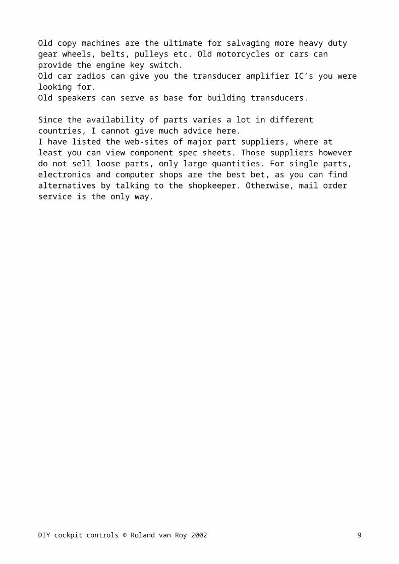
Both Opto-coupler input and output have polarity. The driver circuit needs some form of current limiting (resistor) to avoid damaging the Opto-coupler diode. Diode current around 30mA is a good value. Most opto-coupler diodes have about 1V drop when conducting 30mA current. When driving from 12V, the current limit resistor needs to be:
choose 330 Ohm standard value
When connecting the output circuit to the keyboard, the easiest way of finding the correct polarity connection, is by trial and error: Apply drive to the Opto-coupler input and connect the output to one of the keys; check with Notepad to see whether the key is activated or not. If not, reverse the Opto-coupler’s connection to the keyboard.
Opto coupler connection to keyboard
Opto-couplers are often found in switch-mode power supplies. They usually look like an IC, but have only 6 or 4 pins. Most of these couplers have a diode current rating of max 60mA DC. In the test circuit I used 330 Ohms, which gives 33mA drive current at 12V supply.
The below picture and schematic show the test circuits and setup for relay and Opto-coupler. (Opto-coupler package top view)
Opto-coupler: Vishay, http://www.vishay.com/products do a search on: TCET1103 or SFH620
Toshiba, http://toshiba.com/taec/index.shtml search for TLP620 or TLP421
DIY cockpit controls © Roland van Roy 2002 9

Circuit to convert toggle switch action to momentary switch action using relays.
Many sim cockpit controls are activated by a key-stroke. This means that the keyboard switch is closed momentary, for about 0.1….0.2 seconds. If you connect a real toggle (tumbler) switch across the key-board switch, the constant ON of the toggle switch will result in a constant repeat of the key function due to the auto repeat feature of all PC keyboards. To convert the toggle switch constant ON action into a momentary ON action you need some extra circuit in between the toggle switch and the key-board switch input.The below circuit shows a simple way to achieve this. It makes use of a relay and an electrolitic capacitor.
In the switch position shown, the electrolitic capacitor is discharged. The relay is not active. When the switch is flipped to the +12V position, the electrolitic capacitor is charged to +12V via the relay winding resistance. The pulse charge current through the capacitor and the relay will close the relay switch momentarily. When the switch is flipped back to ground, the capacitor will discharge, again activating the relay switch momentarily. Thus the toggle switch action can be transferred to the keyboard as if a key was pressed momentarily. A 330uF (micro-Farad) capacitor and 12V relay (260 Ohm resistance) will give about 0.2 seconds ON-time. The time is not really critical. You can also use a 5V relay and supply, but you may need to experiment with the capacitor value. (100uF ….470uF). Remember that electrolitic capacitors have polarity. The positive side should be connected to the switch side. Note that you don’t need the diode across the relay for blocking the inductive spike, as the current through the relay has a slow decaying current (via the capacitor) in both directions.
The above circuit is for cockpit functions that use the same key for activating / disabling, like Parking brake, Gear Up / Down, etc.
DIY cockpit controls © Roland van Roy 2002 10

If you want to control a function that uses different keys for activate / disable with one toggle switch, you can use the below circuit where charge and discharge currents are directed to different relays via two diodes, see circuit below. (Used in FUIII engine on/off via car key-switch)
Toggle switch action to momentary switch action using Opto couplers
The same idea can also be build with Opto-couplers, but requires some more components.The Opto-coupler diode cannot be used as time-constant parameter, so some external resistors need to be added for the current limiting and time constant setting.
For toggle to momentary with one opto-coupler, the charge / discharge current needs to flow through the same opto-coupler. If you use a DC opto coupler, you can add a diode bridge, but this is component wise rather wasteful. It’s simpler to use an AC type Opto-coupler, that has two diodes anti-parallel inside. (These types are often found in telephone equipment).
Toggle to momentary with single AC type Opto-coupler
This circuit gives an Opto-coupler ON time of about 60msec
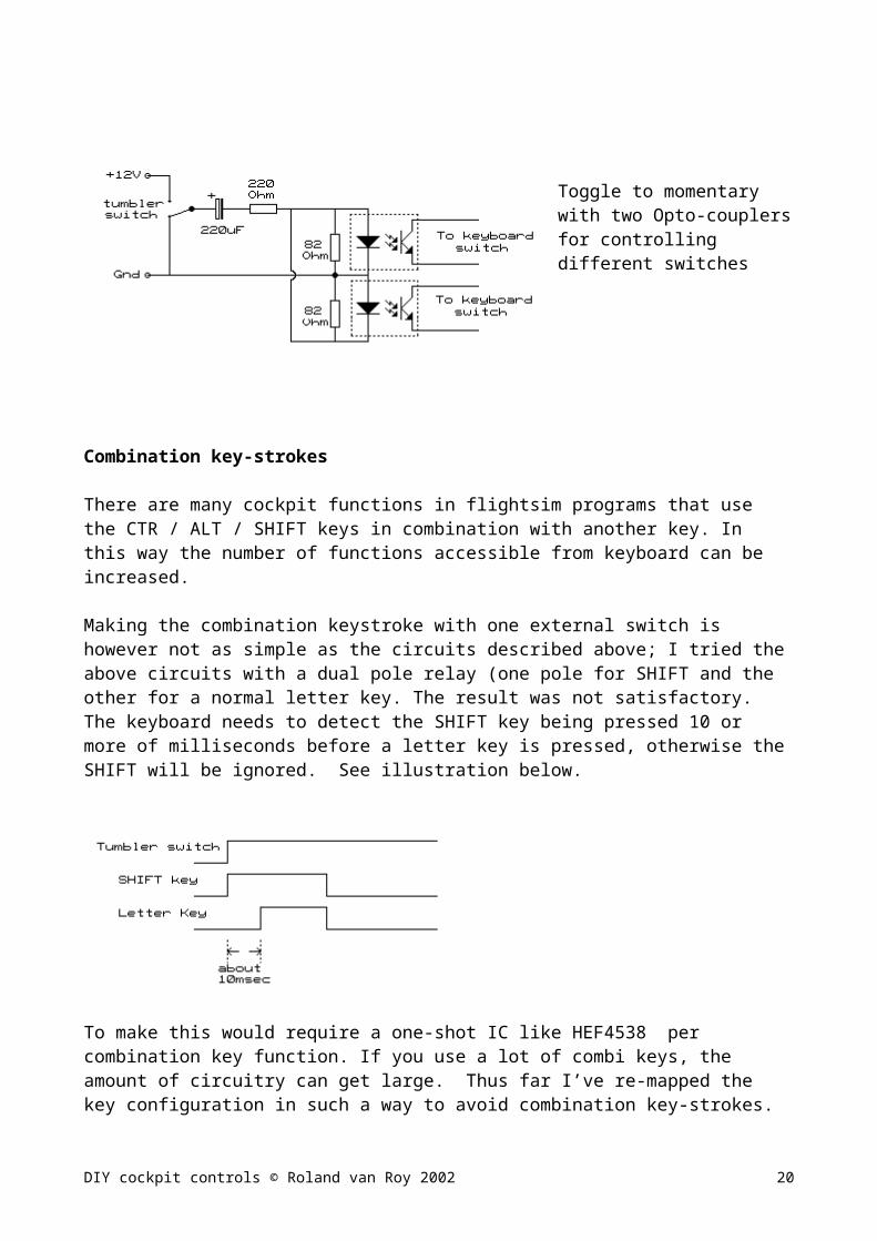
Toggle to momentary with two Opto-couplers for controlling different switches
DIY cockpit controls © Roland van Roy 2002 11

Combination key-strokes
There are many cockpit functions in flightsim programs that use the CTR / ALT / SHIFT keys in combination with another key. In this way the number of functions accessible from keyboard can be increased.
Making the combination keystroke with one external switch is however not as simple as the circuits described above; I tried the above circuits with a dual pole relay (one pole for SHIFT and the other for a normal letter key. The result was not satisfactory. The keyboard needs to detect the SHIFT key being pressed 10 or more of milliseconds before a letter key is pressed, otherwise the SHIFT will be ignored. See illustration below.
To make this would require a one-shot IC like HEF4538 per combination key function. If you use a lot of combi keys, the amount of circuitry can get large. Thus far I’ve re-mapped the key configuration in such a way to avoid combination key-strokes. (See my joykeys.cfg for re-mapping the various function keys to single key action)
DIY cockpit controls © Roland van Roy 2002 12

Making your own joystick connections to PC game port
If you ever opened a normal PC game port joystick, you’ll see that the X and Y axis movements are coupled to two potentiometers (variable resistors, often called potmeters).If you have a joystick with throttle, that movement will go to a third potmeter. You’ll find that the potmeters have three terminals, but normally only the middle and one of the outer terminals are connected to the wiring.
The switches of the joystick are normally small tact switches, that are ON when you press them.
All the wiring then goes via shielded cable to the 15 pin D-shell PC game port which is normally located on the sound card. The circuit connection is pretty much standard.
The left diagram shows the wiring diagram as many audio card makers provide it. The idea was to be able to connect two joysticks, each with X and Y axis and two buttons.
(The pin numbers are normally printed on the connector plastic)
In case you were wondering how to connect MIDI in and out to your General Midi keyboard, I added these connections drawings too. (At least it works with my CASIO WK1500).
For flight simulation, you can use the four available axis to control aileron, elevator, throttle and rudder.
I added the directions of each control w.r.t. to potmeter value. (These are the directions that were used in early DOS games, and may be different for some newer games)
For Flight Unlimited I, II and III, these directions are still valid.
DIY cockpit controls © Roland van Roy 2002 13

If you want to build your own flight controls, you can use the above diagram to connect the potmeters. If you first want to test whether your game port and software indeed work as described, it is handy to make a small circuit according the diagram, (shown at the left), plug it into your PC, and check the functions.(It consists of 4 adjustable 100k potmeters and 4 switches, wired to a gameport connector
After plugging in the test board, you have to select the right kind of joystick configuration and calibrate the axis to the potmeter values. If you don’t calibrate, you’ll find that your potmeters don’t control the functions over the whole range.
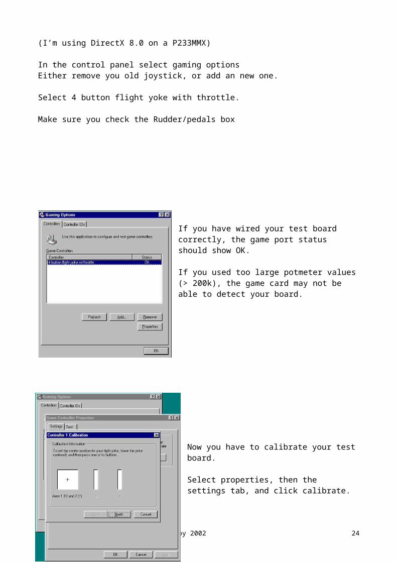
Note: These are Win 98 screen shots(I’m using DirectX 8.0 on a P233MMX)
In the control panel select gaming optionsEither remove you old joystick, or add an new one.
Select 4 button flight yoke with throttle.
Make sure you check the Rudder/pedals box
If you have wired your test board correctly, the game port status should show OK.
If you used too large potmeter values (> 200k), the game card may not be able to detect your board.
DIY cockpit controls © Roland van Roy 2002 14
Now you have to calibrate your test board.
Select properties, then the settings tab, and click calibrate.
This window should appear. Just follow the instructions on the screen.
Basically you’ll let the joystick software know you center settings and min/max range of the potmeters used.
The software can compensate for quite some variation in resistance. It is however recommended to stay close to the 0 – 100k resistor range, which normally gives the best results for linearity, jitter, and drift.
The final result should be like the window at the left.
Turning the potmeters from min to max should give the complete range in the square box and bars.
I found that sometimes one calibration is not sufficient to get good results, and has to be repeated two or three times.
DIY cockpit controls © Roland van Roy 2002 15

Unstable (jittery) controls.
You will sometimes find that the “+” cursor in the lower right of the box will be unstable, (jitter). Also the low end of the bars may show some jittery behavior. This is due to noise pickup of the potmeter wires. When the potmeter is turned for maximum (100k) resistance, the noise can easily be picked up from the wires to the game port. This will give unstable axis movement, and often gives different range after each calibration, as the PC sees variable range at the high resistance setting. As you can see from the wiring diagram, high potmeter resistance corresponds to right aileron, up elevator, right rudder, and idle throttle.
To minimize jitter, use shielded cable for each axis, from potmeter to gameport. Try to keep cables as short as possible, and keep them away from noise sources like switching power supplies.
Sometimes, poor contact of the potmeter wiper to the carbon resistance trace can cause jitter. There are special contact sprays for electronics that can help.
Connecting the unused outer contact of the potmeter to the middle contact can also help, as it avoids the “open contact” condition.
This diagram illustrates how to make your controls less sensitive for noise.
Keep the unshielded ends as short as possible.
DIY cockpit controls © Roland van Roy 2002 16

Joystick switches and POV HAT
The joystick game port has only 4 switches. Most joysticks have a POV HAT, which is used to quickly switch between different views (front/left/right/rear) In flight simulation with single monitor setup, I find 4 views insufficient, as the 45o views are often used when flying a traffic pattern. This requires 8-POV HAT capability.
In principle it is possible to use the 4 joystick switches to make 8 views, by using combinations with multiple switches simultaneously ON.CH flight stick Pro uses this trick to have both joy switches and POV HAT. Their HAT works as following: 12 o’clock: 1,2,3,4 ON 3 o’clock: 1,2,4 ON 6 o’clock: 1,2,3 ON 9 o’clock: 1,2 ON.For each direction, you can use diodes to the corresponding switches, and in this way create a 4 POV HAT using 4 extra switches and 12 diodes. This is described in http://user.fundy.net/jdyarrow/controls/controls_index.html another great info site.
Up to now, I haven’t been able to figure out a way to have 4 joy key switches and a 8-POV HAT via the game port. Therefore, my HAT still makes use of the keyboard view keys in Flight Unlimited III. Here, the numerical key pad keys 8, 9, 6, 3, 2, 1, 4, 7 give a full view circle around the cockpit. My HAT drives those keys. (I found such a HAT switch at a electronics dump store).
It consists of a miniature joystick with 8 contacts around and one center contract. The little pivot can be moved in all directions, and the center contact will touch the outer contacts at 45 degree positions.
To make this 8 direction switch drive the keyboard switches, isolation must be provided. I used 8 opto-couplers for this. Since the switch can only have one active contact at the time, one common resistor can be used for all opto-couplers.
HAT build from 8-position joy-switch.
I put the HAT on the left handle of the yoke: This is more convenient for switching views when flying the traffic pattern, as your right hand will be busy with the throttle. (I often fly Base and Final with left hand on the yoke, and right hand on the throttle).
The left yoke handle with HAT, and the 8-position joy-switch that I used for the purpose.
DIY cockpit controls © Roland van Roy 2002 17
Connecting multiple joysticks to your PC
Light aircraft cockpit controls require more than 4 proportional axis: For example, when you want to add Prop-pitch and Mixture, you’ll need two more axis. Since the standard game port has only 4 axis, you need to add extra devices. There seem to be multiple game-port cards on the market, but I have never seen them in Taiwan. Adding USB devices is a good alternative. There are USB to Game-port converter boxes, that plug into USB but show a game port D-shell connector at the other end. You can use these devices to add 4 more axis to your sim. I have not bought such a device, but I guess the wiring diagram to the joystick is identical to the one I gave earlier.
For my axis extension, I bought an extra USB joystick. I used a Taiwanese brand Rockfire QF605U. When you plug it in, the (Win 98) system detects the stick and puts it under the gameport joystick that was added earlier. The calibration procedure is similar to the one described earlier. This is the window that should show up when connecting two joysticks to the PC.
The Controller ID tab can be used to assign the correct ID to each joystick.
In my original setup, I had the gameport flight yoke assigned as #1 and the USB stick as #2. However, Flight Unlimited III mistook the USB stick as device 1 and gameport as device 2. ….(?)Since I wanted the gameport for primary controls, I had to swap the ID’s as shown on the left.
Flight Unlimited III has support for multiple joysticks, but you have to tell it via flt3.cfg file what stick axis is supposed to do what. For the gameport flight controls, everything worked as intended (aileron/elevator/throttle/rudder) without adding special commands.For the USB stick, I assigned Prop Pitch to axis 1 and Mixture to axis 2 by putting the following lines in flt3.cfg:
prop_pitch_device 2 1 mixture_device 2 2
After that, both prop pitch and mixture were controllable via the USB stick.
(See attachment for joykeys.cfg and flt3.cfg text)
DIY cockpit controls © Roland van Roy 2002 18

Connecting external potmeters to a USB joystick (joystick hacking)
The USB joystick internals are different from normal gameport joysticks. In most sticks, the stick movements are still transferred to potmeter movements. Note: some modern sticks like Microsoft joysticks do not use potmeters, but instead optical encoders. (good for reliability, but unsuitable for hacking).
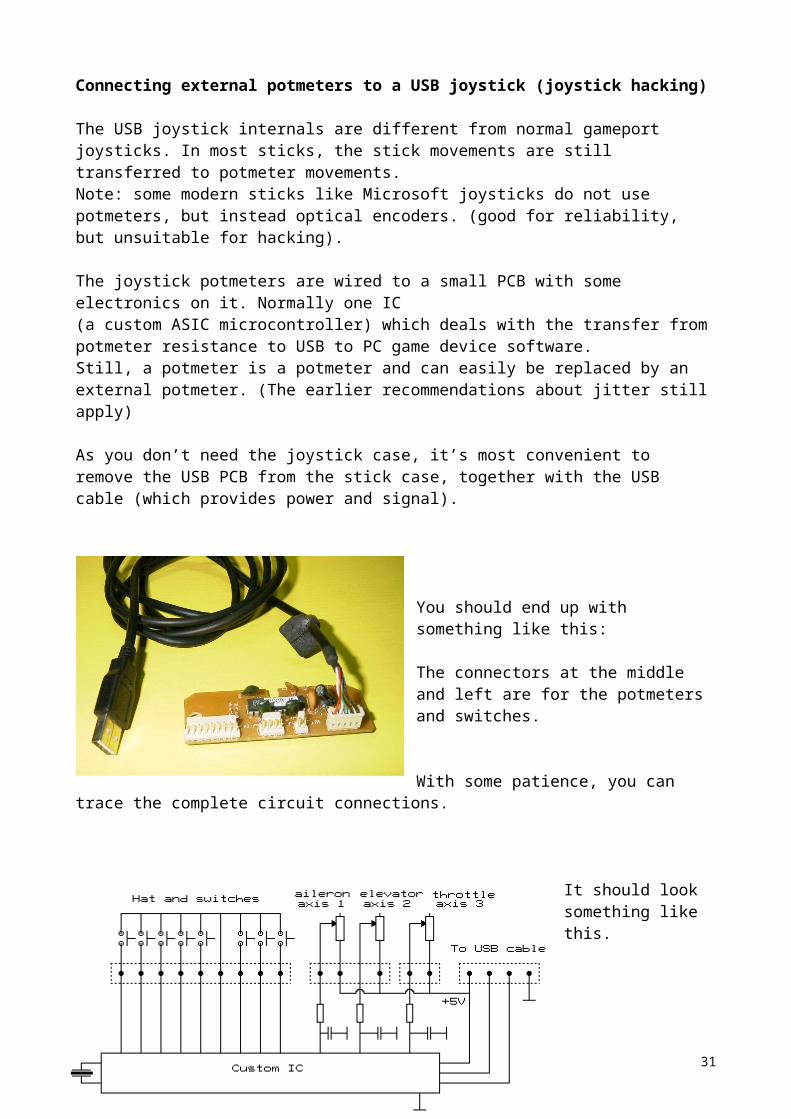
The joystick potmeters are wired to a small PCB with some electronics on it. Normally one IC (a custom ASIC microcontroller) which deals with the transfer from potmeter resistance to USB to PC game device software.Still, a potmeter is a potmeter and can easily be replaced by an external potmeter. (The earlier recommendations about jitter still apply) As you don’t need the joystick case, it’s most convenient to remove the USB PCB from the stick case, together with the USB cable (which provides power and signal).
You should end up with something like this:
The connectors at the middle and left are for the potmeters and switches.
With some patience, you can trace the complete circuit connections.
It should look something like this.
Note the values on the potmeters (or measure them)
In my case they were all 100k, so my external 100k potmeters worked fine with the USB PCB.
I only used axis 1 and 2, so I disconnected the rest, and externally connected the prop pitch and mixture potmeters to the corresponding connector pins. Basically you could also make use of the switches, but for some reason, Flight Unlimited III does not recognize the switches of the second joystick device. Keep in mind that you need at least one switch to calibrate your joystick, so connecting one external switch is required. (I would suggest not to solder to the PCB directly. Try to find fitting connectors, and solder the external potmeter (shielded) wires to the wires of the connectors)
DIY cockpit controls © Roland van Roy 2002 19
Potmeter wiring issues
Use your Flightsim program for verification of the various potmeter controlled cockpit functions.If you find that one of the control functions works reversed, the potmeter wiring needs to be changed: leave the middle wire unchanged, but the outer wire needs to be swapped to the other outer connection
Reversing control direction
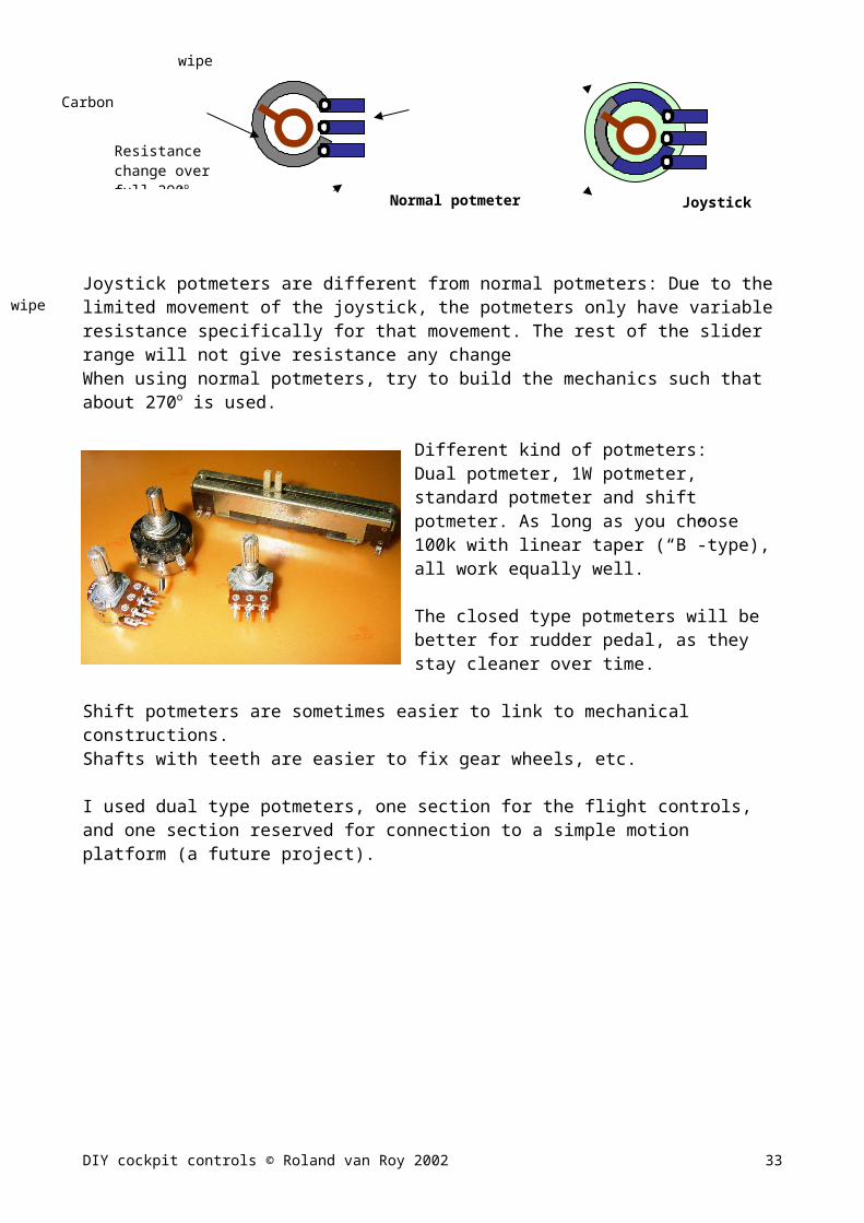
Joystick potmeters are different from normal potmeters: Due to the limited movement of the joystick, the potmeters only have variable resistance specifically for that movement. The rest of the slider range will not give resistance any change When using normal potmeters, try to build the mechanics such that about 270o is used.
Different kind of potmeters: Dual potmeter, 1W potmeter, standard potmeter and shift potmeter. As long as you choose 100k with linear taper (“B”-type), all work equally well.
The closed type potmeters will be better for rudder pedal, as they stay cleaner over time.
Shift potmeters are sometimes easier to link to mechanical constructions. Shafts with teeth are easier to fix gear wheels, etc.
I used dual type potmeters, one section for the flight controls, and one section reserved for connection to a simple motion platform (a future project).
DIY cockpit controls © Roland van Roy 2002 20
wiper
Resistance change over full 290o movement
wiper
Carbon (resistance) trace contacts
Joystick potmeter
Only resistance change over middle section
Normal potmeter

Making connections
Connecting all the cockpit controls can be a tedious work. Try the functionality by checking one function at the time. For the keyboard driving functions, I use Notepad to check the correct key action.
For making connections, the flat ribbon cable with matching connectors is very handy. (The types that are used for connecting Floppy-drives, Hard-drives and CD ROM to your PC main board) The connectors are available in various pin count size, from 10 to 40 pins. You can also get the fitting male pins (2.54mm pitch, they will fit perfectly on experiment board. You can use pre-assembled cable with connectors, but the loose parts can easily be assembled by yourself: The connectors have a top and bottom half, that need to be pressed together in a vise with the ribbon cable in between. Ribbon cable can be bought by the meter.
Since all circuits are basically one-piece projects, I normally don’t bother making real circuit layouts. I use experiment board with 2.54mm pitch copper islands, and place the components in a logic fashion. Adjacent connections are done with solder, longer connections with 0.3mm enamelled copper wire. (You can remove the isolation at the wire ends by heating them with your soldering iron for a few seconds). This method works quick, and the transformer wire isolation is good enough to avoid shorts over crossing wires.
I normally try to build with some ease for disassembly in mind. Modular building blocks help keep things organized and will make trouble shooting easier.
Using labels for various connections with polarities (i.e. supplies) will make troubleshooting easier. For the keyboard wiring connections you cannot do without clear labels.
The key to good electronics soldering: Not too hot solder iron (40W or so), wipe the tip of the iron clean on a damp sponge after every solder point, solder quick, not more than 5sec (after that, the solder degrades). Soldering wires to connectors: First put a coat of tin on each end of the leads, then solder together.
DIY cockpit controls © Roland van Roy 2002 21

6. Cockpit console layout
This section shows the functionality of the setup. The controls are placed at roughly the correct areas, with some modifications due to limited space, table height, flightsim ergonomics, etc. Increase your document zoom to see more details.
Yoke function keys
The yoke contains those key functions that have to do with sim views and ATC communications. The HAT is at left side on purpose, as view cycling and (right hand) throttle control is otherwise difficult.
DIY cockpit controls © Roland van Roy 2002 22
Engine start/stop
Speed brake Reverse thrust
Parking brake
Console power
Transducer power
Yoke
Gear
Gear indicators
ThrottleProp pitch Mixture Flaps
Elevator trim
Rudder trim
Auto pilot switches
Auto pilot LED indicators
Game keys
Number / game keys
VER LEV YAW ALT HDG NAV APR APTAXI LIGHTS
LANDING LIGHTS
CARB HEAT
PANEL LIGHTS
PITOT HEAT
NAV LIGHTS
BEACON LIGHTS
STROB LIGHTS
Miracle up
Miracle down
Game Pause
Inflight Map
Show taxi line
Tape strip
ESCY (Yes)
Auto Tune
TAB(cycle radios)
Space(Communicate)
ENTER
1 2 3
4 5 6
7 8 9
0 .
Numbers 1 – 9 for ATC menu select
Communicate
Ente
Cycle Model detail
Cycle cockpit views
Pilot controlled lighting (PCL)
F5 (outside) view
Joystick controlled panning
Joystick controlled zooming
8-POV hat

Cockpit console dimensions
DIY cockpit controls © Roland van Roy 2002 23
VER LEV YAW ALT HDG NAV APR AP
1 2 3
4 5 6
7 8 9
0 .
72mm
15mm
195mm220mm
95mm130mm
310mm485mm
800mm
170mm
155mm
100mm
40mm
20mm
14mm
85mm
55mm
46m
m
40m
m
40m
m
43m
m
20m
m72
mm
145m
m
52m
m87
mm
57m
m
290m
m36
mm
53m
m
30
10
74m
m25
mm
1313
62mm
320mm
30mm
40mm
60mm
100m
m32
mm
25m
m
85m
m
180m
m
32m
m
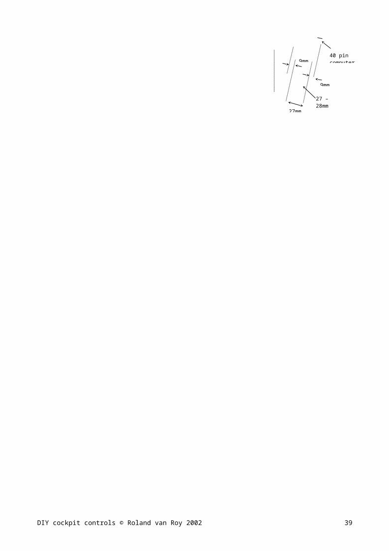
76 degrees
9mm
9mm
27mm
Tack switches (from old VCR) on PCB
0.2mm transformer wire
40 pin computer connector
Front cover to hide nut
Rear cover to mount connector
27 – 28mm multiplex
Number key pad from old keyboard mounted under 45 degrees
key pad from old keyboard mounted under 45 degrees
Ignition key switch from old car or motor cycle
Switch-row from old equipment
8-direction HAT stick to keyboard via opto couplers or relays
Flightsimming setup
A basic drawing of a possible setup configuration. I found the drawer-style console mounting very handy, as it allows you to shift it out partly and make small modifications and tests without having to disconnect everything. The drawer action has to have some friction, to avoid console movement when pulling the yoke.The mouse is sometimes necessary for navigating the inflight map, or enabling some cockpit switches/controls that have no keyboard support, and could not be build into the console.(Cowl flaps / VOR adjust, etc). Flying the sim does not require a separate keyboard, so the space in front of the monitor can be used for sectionals, notes etc. It is however recommended to have a second keyboard somewhere that can be activated via a switch (see cockpit wiring overview). This keyboard may be necessary to make the required modifications to your joykeys.cfg and flt3.cfg files, then switch back to the console keyboard and check the functions.
DIY cockpit controls © Roland van Roy 2002 24
Drawer cabinet Home made subwoofer750x600x260mm
mouse
18mm board as table top
PC
Cockpit console sits on V profiles, can be pulled out as a drawer
610m
m
750m
m
8” woofer

7. Cockpit controls description (Flight yoke)
Home build flight yoke for flight simulation
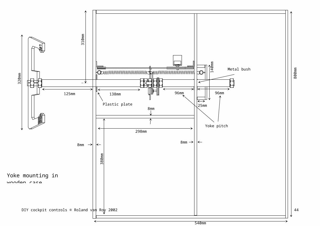
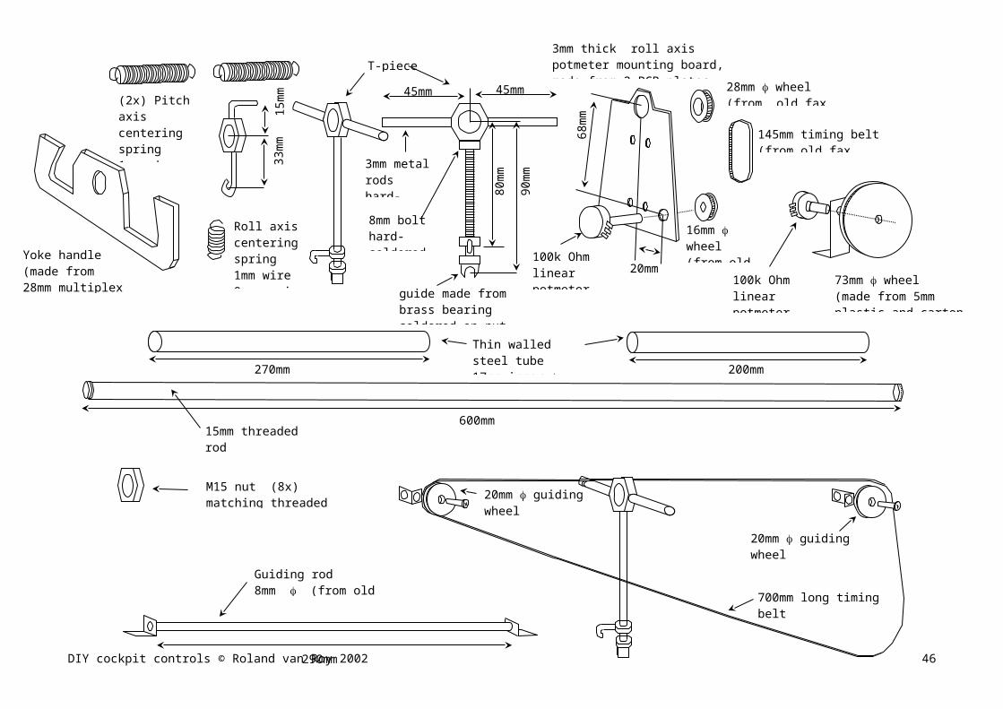
These pages show the construction of a flight yoke for light aircraft. The yoke pitch and roll movement are roughly equal to the movements of Cessna Cardinal yoke (I got those from a friend in the States who owns one).The tension adjustment for roll and pitch may take some experimenting with different types of springs (or bungee cord) This flight yoke has been built into a wooden case, that is mounted like a drawer under the computer table. The wooden case can also house other control items like throttle, flaps and gear lever and various switches, to form a complete flight control console. The interface for roll and pitch control to PC can be done via standard joystick port, using the X and Y coordinate of joystick A input.
I would suggest with starting with the wooden case, and then gradually continue with the metal parts. The drawing shows which dimensions are setting the pitch movement, so you can modify if needed. The front tube that fits over the threaded 15mm rod must leave some room to pass the electric wiring from yoke handle to the case. How many wires you need, depends on the amount of switches. I used 40 wires (40 x 0.2mm transformer wire stuck between tape) for the Hat and 17 switches. The bearings for the control column should not be too tight as deformation in the wooden box would then hamper the column movement. The PCB (printed circuit board) plate I used are the glass fiber reinforced type (CEM4) You can leave the copper layer on. It is very strong material for all kinds of mounting plate uses.
DIY cockpit controls © Roland van Roy 2002 25

DIY cockpit controls © Roland van Roy 2002
Guiding rod keeps T-piece fixed over roll action
Roll axis centering and end stops
Roll info wheel locked between nuts
Pitch axis potmeter Locking nut T-piece
roll axis potmeter
Roll action
Pitch action
mounting boardFixed to T-piece with tie-wraps
Timing belt fixed to T-piece turns pitch potmeter
T-piece moves with pitch action but not with roll action
Steel tube fit over fixed to threaded rodTape on rod ends centers tube
Pitch axis centering springs Fixed to T-piece and wooden frame (not shown)
All yoke components Detail of T-piece and roll centering Detail of roll axis potmeter linkage
26
DIY cockpit controls © Roland van Roy 2002
380m
m
310m
m
800m
m
125mm 138mm
8mm
8mm
96mm 96mm
540mm
298mm
320m
m
25mm
140m
m
8mm
Plastic plate bearing
Metal bush bearing
Yoke mounting in wooden case (top view)
Yoke pitch movement
27

DIY cockpit controls © Roland van Roy 2002
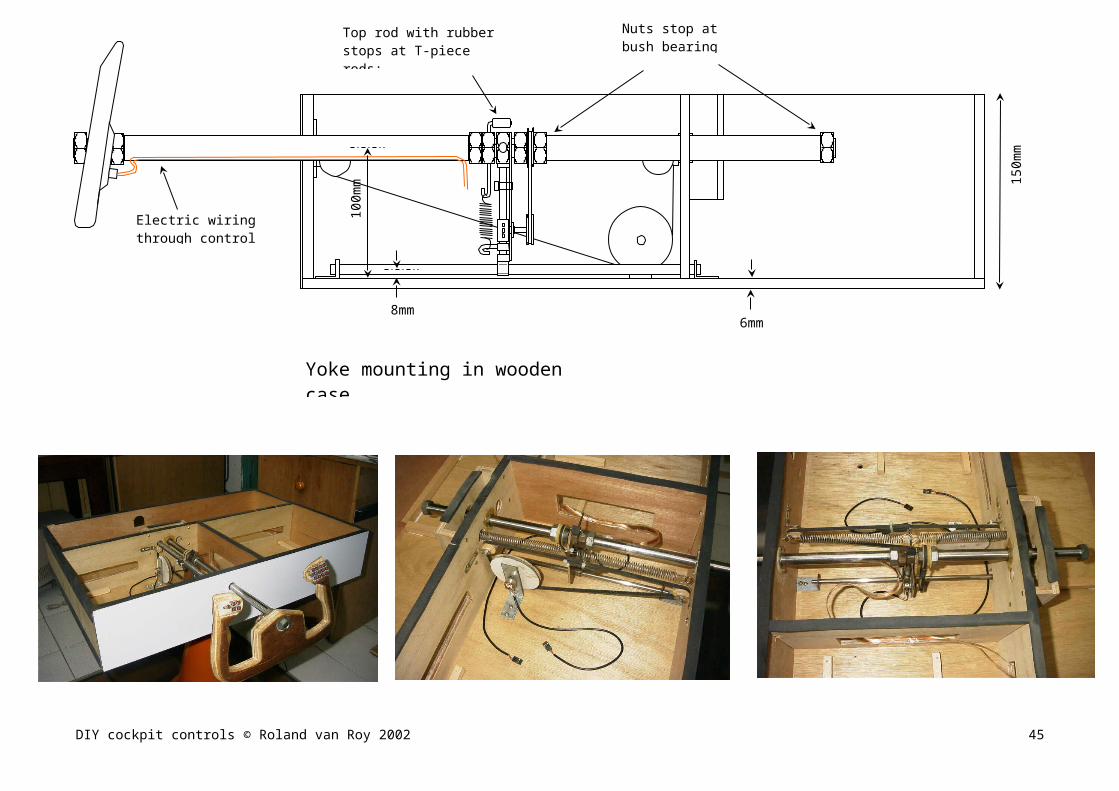
8mm
100m
m 150m
m
6mm
Yoke mounting in wooden case (side view)
Electric wiring through control column
Top rod with rubber stops at T-piece rods: Roll movement: 170 degrees
Nuts stop at bush bearingPitch movement 96mm
28

DIY cockpit controls © Roland van Roy 2002
600mm
270mm 200mm
80m
m
90m
m
45mm45mm
33m
m15
mm
68m
m
20mm
28mm wheel (from old fax machine)
16mm wheel(from old fax machine)
145mm timing belt(from old fax machine)
100k Ohm linear potmeter (100kB)(roll axis)
3mm metal rodshard-soldered on nut
8mm bolthard-soldered on nut
guide made from brass bearing soldered on nut(matched to guiding rod)
Roll axis centering spring1mm wire8mm spring 25mm long
(2x) Pitch axis centering spring1mm wire13mm spring 45mm long
T-piece
Thin walled steel tube 17mm inner 17.5 mm outer
15mm threaded rodM15 thread
M15 nut (8x)matching threaded rod
Guiding rod 8mm (from old printer)
290mm
100k Ohm linear potmeter (100kB)(pitch axis)
73mm wheel (made from 5mm plastic and carton edges)
20mm guiding wheel (made from wood)
20mm guiding wheel (made from wood)
700mm long timing belt (from old printer)
Yoke handle(made from 28mm multiplex board)
3mm thick roll axis potmeter mounting board, made from 2 PCB platesFixed to T-piece with tie-wraps
29

Description of cockpit controls (other parts)
This section gives some examples of possible solutions for the different cockpit controls. All pieces are screwed to the front (or bottom) of the wooden cockpit case.
Gear lever
Moving the lever up and down flips the toggle switch. The toggle switch arm has been extended to get better switch action. Interfacing to keyboard via the toggle to momentary switch action circuit.The same switch can be connected to the gear light indication circuit as well.
Gear up / down indicator.
When moving the gear lever up and down, the gear indicator lights are changing as well. For most light aircraft, there are three green gear down and locked indicators, and one red gear in transition indicator. Although the flightsim screen will also show them, I found it handy to have real lights next to the gear handle as well.
From the sim, you can check the light sequence and timing, and with a small circuit driven from the gear lever switch, you can make the four lights behave in the same manner.
Gear up/down lights sequence
DIY cockpit controls © Roland van Roy 2002
78mm
17mm
16mm 41mm
24mm
35mm diameter
+12V
To electroliticcapacitor
Gnd
40 degrees
Extended switch lever
(2 round pieces of 8mm multiplex)
30
Gear lights circuit:
The above circuit shows the gear lights driving circuit and the connection to the gear lever switch. In shown position, the gear switch output is low. This should correspond to gear up position. The three upper LED’s and the red LED are dark. When the gear switch is flipped to gear down position, the upper one-shot gets triggered, and produces a positive pulse of about 4.7seconds at the Q output. (determined by R*C of the upper one shot timing components) This pulse drives the lower transistor and the red LED will light for 4.7 seconds. At the same time, Q of the upper one-shot produces a low (going to 0V) pulse of 4.7 seconds. This pulse will pull down the base of the transistor that drives the three gear down LED’s. After 4.7 seconds, Q goes low, and Q goes high. The red light goes out, and the green lights light-up driven by the high output of the gear switch.
When the gear lever is again pushed in the gear up position, the switch output goes low, and the green lights go out. At the same time, the lower one-shot is triggered, and its Q output sends a high pulse of 4.7seconds to the red LED driver transistor.
You can change the gear transition time by changing the 470k resistor value or the 10uF capacitor value of upper and lower one shots: Upper determines up down time, lower determines the down up time.
(For info on the IC’s, see the Elevator Trim section)
DIY cockpit controls © Roland van Roy 2002 31

Gear light indicator components and wiring setup
DIY cockpit controls © Roland van Roy 2002
2x BC548
E
BC
+
+
10uF
10uF
470k
470k
1nF 1k
10k
0.1uF
220 680
Green LED’s Red LED
4538
1 8
16 9
4148
4148
4148
Ground+12V
Gear switch center contact
0.3mm isolated jumper wire
Component (top) viewPCB: 75mm x 30mm 2.54 mm pitch experiment boards
32
Parking brake
Just a fun piece of mechanics that should give you the feeling of pulling or releasing the brake.Interfacing to keyboard via the toggle to momentary switch action circuit.
Speed brake
Another simple mechanical construction. I’ve tried to make it resemble the Mooney speedbrake.Interfacing to keyboard via the toggle to momentary switch action circuit.
DIY cockpit controls © Roland van Roy 2002
220mm
125mm
40mm
90mm
18mm
55mm
Wooden handle
8mm steel rodfrom old printer
Spring pushes and turns
Shown in parking brake ON position
Shown in parking brake OFF position
Spring wire on switch lever
90mm
55mmTravel: 28mm
Shown in retracted position
Rod and fitting plastic tube from old printer
Shown in extended position
Knob cut from 22mm wooden stick
33

Flaps lever
This flaps lever is a very simple one: It does not show the different flap settings, as many light aircraft have different number of flaps steps. The switches are momentary types (micro switches) so can be connected to the keyboard directly.
The U-piece and PCB “spring” keep the flap lever centered and provide more centering force. (The force or the micro switches was too little, and made the lever bounce when released.)
DIY cockpit controls © Roland van Roy 2002
U-piece slides backwards when flaps lever goes up or down
PCB acts as spring against U-piece
Extend flaps micro switch
Retract flaps micro switch
To keyboard “extend flaps” key
Lever from old equipment
Piece of PVC plate
8mm multiplex
8mm multiplex
50mm
43mm
55m
m
60mm
33m
m
55m
m
40mm
10mm
20m
m
10mm
58mm
1.5mm PCB plate (glass fiber type)
36m
m
20m
m
35mm
18mm
Tension adjustment screw
8mm
50mm50
mm
8mm multiplex
34

Throttle, Prop-pitch and Mixture controls
The lever throw distances are close to actual Cessna Cardinal. I used rotation type potmeters, but things could probably be simpler when using slide potmeters.
The throttle potmeter uses about 270o rotation, but prop and mixture use about 200o rotation. However, after calibration, the joystick calibration software will correct for this, and all levers will have full control range in the flight simulator cockpit controls.
DIY cockpit controls © Roland van Roy 2002
35m
m
Thro
ttle:
50m
mPr
op P
itch:
35m
mM
ixtu
re: 3
5mm
154m
m
Thro
ttle:
50m
mPr
op P
itch:
35m
mM
ixtu
re: 3
5mm
100k linear potmeter(100kB)
45mm 58mm
Trottle Prop pitch Mixture
Idle
Max
Decrease
Increase
Lean
Rich
70mm 70mm100mm
Knobs cut from 30mm wooden rod
0.6mm wire, fastened to both ends of the control rod, and goes around the wooden disk on potmeter shaft where it is also fixed in the middle
Throttle potmeter connection goes to joystick port Y-coordinate of B-joystick connection
Prop-pitch and Mixture potmeter connections go to USB joystick X/Y axis connection
35

Rudder pedals
DIY cockpit controls © Roland van Roy 2002
415mm
32mm
127mm
80mm
32mm
80mm32mm
58mm
32mm
152mm
530mm
310mm 90mm 78mm78mm
48mm137mm
Centering pieces
Rubber stops
Wheels fixed to centering pieces push crossbar in mid position
100k Ohm linear potmeter with 11mm gear wheel (from old VCR) on shaft(connect to X-axis of B-joystick)
52mm gear wheel (from old VCR) fixed on crossbar
Wheels (from patio door slider) recess mounted through slider board to make rudder pedals slide more smoothly
Left Rudder pedal assembly (with toe brake function) mounted on slider boards
Springs: 1mm wire, 8mm coil56mm long
To left toe brake Keyboard key
Springs: 1.5mm wire, 8mm coil65mm long
8mm multiplex bottom plateAdd rubber pads for better grip on floor
8mm multiplex
0.7mm hard table top covering
36

Rudder pedal with toe brake assembly
The key to good rudder pedal action is smooth sliding parts and strong centering force.The sliding parts need to be some length, to avoid lifting the rear section when braking. Try to make use of (almost) the full potmeter rotation for better accuracy
It is possible to use proportional toe brakes by converting the pedal tilt action into potmeter rotation action by means of gears. Potmeters should then be connected to a hacked PCB from USB joystick.I haven’t tried this, as I’m quite satisfied with on/off brake action.
DIY cockpit controls © Roland van Roy 2002
90mm
54mm
90mm
21mm40mm
50mm
30mm
50mm
90mm
200mm
55mm x 65mm x 35mm (h) woodmounted with long screws to sliding board
Toe-brake micro switch with 50mm long switch lever
10mm bold & nut
10mm bold hard-soldered on U-plateU-plates from
1.5mm iron plate
2mm wire, 15mm coil , 10mm long springs push pedal backward
50 x 50mm V profile (extruded aluminum) 110mm long
8mm multiplex board footrest
37

Rudder and Elevator trim wheels
The rudder and especially the elevator trim wheel function is a very nice addition to the cockpit controls. Since elevator trim is used a lot, I have tried to make it come (somewhat) close the the real thing found in light aircraft. The whole assembly is mounted below the throttle/prop/mix section, and elevator trim is quite easy to reach. Rudder trim is somewhat low, as I needed to place the small keyboard for radio frequency input as well. The trim interface is via rotary encoders, to a pulse shape circuit, to the keyboard trim up/down/left/right keys.
For the elevator trim, there is a small gear section that makes the turn sensitivity more realistic. Rudder wheel is directly mounted to the rotary encoder. The wheels need some friction, so I used dishwasher sponge (don’t laugh) in between the wheel and the wooden frame.
DIY cockpit controls © Roland van Roy 2002
Elevator trim wheel
Rudder trim wheel
Small keyboard for radio frequency input
Trim down
Trim up
38
Rear view drawing of the trim wheel section
DIY cockpit controls © Roland van Roy 2002
Rudder trim rotary encoder
To rudder trim decoder circuit
125mm trim wheel from PVC plate
Dishwashing sponge for wheel friction
52mm gear wheel from old VCR
22mm gear wheel from old VCR
125mm trim wheel from 5mm PVC plateFor the rim, you can use the isolation of 6mm TV grade coax cable
Elevator trim rotary encoder
Dishwashing sponge for wheel friction
To elevator trim decoder circuit
170mm
20mm
110mm
28mm
85m
m
50mm
58m
m
28mm
290m
m
30mm
39

Rotary encoder to keyboard stroke interface circuit for rudder and elevator trim.
In cockpits there are a number of rotating knobs, like radio tuning, OBS, etc. Also rudder and elevator trim are rotating inputs. For radio tuning, I still use the numerical keypad as frequency input. Therefore I mounted a small keypad to the controls console, cut out of an old keyboard, and wired it to the main keyboard number keys. In Flight Unlimited III, OBS needs to be rotated by means of mouse. No keyboard input seems to exist.
For adjusting the elevator trim, you have to press pre-defined trim-up and -own keys repeatedly. Same for rudder trim. Real aircraft use trim disks that you have to rotate to change the trim setting. Since elevator trim is used very often, it adds lots of realism in the sim when rotating the trim disk a couple of notches in stead of pushing a key a couple of times.
In the Cessna, the rudder and elevator trim disks need to be rotated 2.5 turns for trim limit to limit. In Flight Unlimited III, the elevator trim key needs to be pressed 180 - 200 times limit to limit, the rudder trim about 110 - 120 times limit to limit. (both seem to vary a bit over the different airplanes)
To make that amount of switch pulses over 2.5 turns is best done with a rotary encoder. This is a little device that looks like a potentiometer, with three connections, but internally has two wipers that pass a number of contacts when rotated. The mid connection is connected to the wipers’ center, while the outer connections are the contacts that each wiper passes. The reason for two wipers is the fact that the circuit that decodes the on/off cycles of the wipers also has to distinguish whether the rotary is turned clockwise or anti clockwise. This is accomplished by setting the inner and outer contacts 90o out of phase. I used Alps http://www3.alps.co.jp/index-e.html 12mm rotary encoder search for EC12E2420801. Below pictures show the encoder and the switching waveforms.
This type encoder produces 24 pulses per rotation. For the elevator, 2.5 turns should produce about 200 pulses. I added a gear ratio of 1: 2.5 between trim disk and encoder, giving 150 pulses for 2.5 turns. For the rudder trim I did not add any gear, as it is less used anyway.
DIY cockpit controls © Roland van Roy 2002 40

Limitations of keyboard when driving with pulsed switches.
After doing some experiments with the rotary encoder directly connected across the keyboard switches, I found that the keyboard controller IC (an old Intel P8049AH in my case) cannot detect too narrow pulses. (I checked this by rotating the encoder fast and checking with Notepad to see the key output). If key ON pulses are less than 20 msec, the key press is ignored or unstable. I also found that the time between two key presses cannot be too short either: The OFF time between two ON pulses needs to be more than 20 msec as well. This means that the rotary switch outputs need to undergo some pulse width modification before they can drive the keyboard. As mentioned before, the keyboard switches do not have a common ground, and therefore are best driven by means of a relay or Opto-coupler. For repeated switching, relays are too noisy. In this case, Opto-couplers are preferred.
The drawing at the left shows the rotary switch action (slow and fast turning) and required keyboard switch action to maintain stable key recognition.
When the rotary encoder is turned very fast, the buffer circuit in between maintains the speed that the keyboard controller still can follow.
Circuit for elevator trim rotary encoder to elevator trim keyboard strokes
DIY cockpit controls © Roland van Roy 2002 41

In the above circuit, the D-flipflop (one-half of CMOS HEF4013 IC) determines which direction the rotary encoder turns. When turning in one direction, HEF4013 Q output will be high and Q will be low. When turning the other direction, the situation reverses. When high, these outputs Q and Q enable upper and lower one-shot circuits build with IC HEF4538. These one shot circuits are used to re-shape the pulses from the rotary encoder as shown in the drawing. Since Q and Q are each others inverse, only one section will drive the keyboard via one opto-coupler, depending on the turning direction. For info on the IC’s do a search at http://www.semiconductors.philips.com/.
The HEF4538 IC is connected as two non-retriggerable one-shots. The first one-shot has a twice longer time than the second. Both are triggered by the pulses of one of the switches of the rotary encoder. The first negative going pulse will produce a pulse at both Q outputs. The pulse time duration is equal to R*C as connected to the timing pins. The Q output pulse of the first one-shot lasts 0.07sec, that of the second 0.033sec. As long as the first one-shot output is high, neither one-shot can be re-triggered by additional pulses of the rotary encoder. Even if the encoder is turned very fast, the opto-coupler is driven with a pulse that is at least 0.033sec high and 0.032sec low. Since CMOS IC’s cannot deliver a lot of current, I added an emitter follower to drive the Opto-coupler. BC548C (or BC547) is a standard small signal NPN transistor. (see http://www.semiconductors.philips.com/) The circuit is not perfect, as there are occasionally false pulses from the other section while tuning one direction. Adding 1 nF (0.001uF) capacitors at the rotary switches may help somewhat. (I did not use them). For elevator trim, I found the performance satisfactory.
In principle, the same circuit can be used for rudder trim. Since rudder trim is normally not rotated very fast, some simplifications can be made: I deleted the trigger inhibit after initial ON pulse, thereby saving one IC. The rotation direction detect circuit can be made from the other half of the HEF4013 IC. The circuit is shown below.
DIY cockpit controls © Roland van Roy 2002 42

Elevator trim rotary encoder to keystroke converter circuit waveforms:1&2: rotary encoder switches output (quick turn clockwise)3: First one-shot output (HEF4538 pin 6)4: Second one-shot output (pin10) that drives the opto-coupler As can be seen, the very fast turn will give 32msec output pulses that the keyboard still can follow.(Although you loose some pulses from the original encoder output, the final pulse count is the most you can get via the keyboard, and works much better than w/o pulse shape buffer).
DIY cockpit controls © Roland van Roy 2002
Rudder trim rotary encoder
Elevator trim rotary encoder
Trim up
Trim down
Trim left
Trim right
+12V Ground
Supply connection
4013
4538 4538
4538
1 8
16 9
1 7
814
220k
10k
220k
220k
220k22
0k
220k
10k
10k
10k
220
220
220
220
Opto-couplers
0. 33uF0. 33uF
0.15uF0.15uF
0.15uF
0.15uF
0.1u
F
BC548
BC548
BC548BC548
E
B
C
0.3mm isolated jumper wire
Component (top) viewPCB: 90mm x 50mm 2.54 mm pitch experiment boards
43
8. Adding Tactile Transducers to your sim setup
The (unfortunately only one) time that I took a introduction flight in a Cessna 172, the instructor let me take the left seat and we did a couple of traffic patterns. After all the flight simming at home, one of the things that struck me was the amount of vibration from engine and landing wheels (The landings I made were not that smooth). Your rear, hands and feet get a lot of vibration feedback, especially when going to lower RPM settings (maybe the engine was running a little rough, as the throttle lever was really shaking).
You can add these kind of vibrations to your sim by placing Tactile Transducers at various places in the sim setup. Below your rear is the obvious place, but your hands and feet are much more sensitive to vibration, therefore I also placed a small transducer on the throttle assembly and on the rudder pedals.
The transducers are driven by the audio output. If your flightsim and aircraft have good wave files, with frequencies going down to 5 – 10 Hz, you will get great sensations from your hands when touching throttle or elevator trim. Your feet are surprisingly sensitive, and you need very little transducer driving power to get good feeling of engine, spoiler wind vibration, and wheels touchdown. Flight Unlimited III has excellent low frequency sound for the Mooney Bravo, Stemme motor glider and Lake Renegade water plane. The turbo engines of the Beechjet don’t do much for vibrations, but the gear down vibrations and landing on runway bumps are fine. There are also lots of downloadable airplanes at AVsim.com that you can try. You can also modify existing wave files and add some low frequency waves at key areas. Keep in mind that 5Hz – 60Hz is the range of interest.
You can buy tactile transducers, but you can easily make your own for very little money and good results. Tactile transducers can be made from old low frequency speakers. You need to partly remove the paper cone, mount a metal strip to the speaker frame, glue it to the remaining cone (that is connected to the voice coil), mount some weight at the center of the metal strip, and that’s it. In this way, the voice coil now drives a heavy weight (0.5kg or so) but no surrounding paper. You can connect the transducer to an small power audio amp (20W car radio IC amps are ideal) which is driven from your PC sound card. (you need to mix L and R channel together, and add some low pass filtering (around 100Hz roll-off.) The transducer will produce vibrations in the 10 – 60 Hz region, but hardly any sound. The procedure is described in http://www.hometheaterhifi.com/volume_4_2/tactile.html , (a great DIY site), which shows how to make big transducers for home theater.
For flight simming, you don’t need very large transducers or high driving power. The one mounted under your seat is the biggest, as the seat cushion takes some of the energy away. I used an old 8” Woofer from the dump that had damaged paper cone, but intact voice coil and suspension spin.
The one for mounting on the throttle unit can be smaller, 6” or so. Due to space reasons, you may not want a round speaker. Oval speakers work fine as well, but they need to be the woofer (low frequency capability) kind. These are often used in bigger size TV sets. I used a 180x60mm TV speaker type. If you get some rattling from loose parts in the cockpit controls box, you can use some cloth or adhesive rubber strips to fix things. Even you monitor may start to rattle, as vibrations get transferred from cockpit to table. I placed the whole throttle unit on rubber strips, then I taped adhesive rubber strips around the cockpit case at all the areas where it touches the table or supports. That solved most of it. It is really cool to see your throttle lever shaking after engine startup.
DIY cockpit controls © Roland van Roy 2002 44
For your feet, you can mount the whole rudder pedal assembly on rubbers, and put one 5” transducer on the base board. It works, but I got a lot of rattle sounds from the springs. Therefore, I mounted very small 1.5” multi media speakers with some added lead weight glued on the cone, then mounted directly on the pedals themselves. With only 3Watts / speaker you get plenty vibrations, and little rattle.
Basic construction of home made transducer
Throttle and rudder pedal transducers
DIY cockpit controls © Roland van Roy 2002
Speaker frame
Dust cap
Voice coil suspension
Paper cone
MagnetVoice coil
1: Speaker cone cut away half
4: Lead mounted on rubber (from inner tire of bicycle), fixed with cable ties to metal strip
2: 0.4 mm metal strip mounted with bolts to speaker frame (add some rubber in between
3: Lots of epoxy glue to fix metal strip to dust cap and cone(Apply in layers)
Old speaker (round or oval)
The amount of lead mounted on the metal strip needs to be determined experimentally: Drive the speaker with amplifier that has your flightsim engine noise (somewhere at idle) as input signal. Continue adding lead until best vibration is obtained
Epoxy glue poured into cone
Piece of lead glued on top of epoxy
Mini size speaker 1.5 – 2”(with low frequency capability)
Warning: small size speakers with soft cone may deform due to the weight of epoxy and lead, causing the voice coil to rub against the magnets. Sounds awful
45
Mounting of transducers at throttle unit and rudder pedals
Chair transducer and mounting
Transducer amplifier circuits
The power requirements for driving light aircraft flightsim transducers is not so high; about 20W (real Watts, RMS power). Attention has to be paid to the amplifier circuit to make sure that the amplifier has sufficient low frequency bandwidth. Single ended amplifiers with capacitive coupling between amplifier and speaker would require very large capacitor values to reach 5Hz. Amplifiers with direct coupling between amplifier and speaker are preferred. You can either go for amps that have + and – supply that drive a speaker to ground reference, or you can choose Bridge Tied Load (BTL) structure, where the speaker is connected between two amps, where the amps have opposite polarity. BTL is most easy, supply- and component-wise. Building small power amplifiers is very easy with currently available IC amplifiers. They require very few external components, have various protections build-in and are cheap. You can choose from SGS-Thompson http://us.st.com/stonline/index.shtml , Philips Semiconductors http://www.semiconductors.philips.com , National Semiconductors http://www.national.com to name a few. All you have to care about is total power, gain, max supply voltage, speaker resistance, heatsinking.
For my transducers I used Philips TDA1554Q which in BTL configuration has two channels. As I wanted to adjust the “volume” of each transducer function separately, I used 2 IC’s, leaving me with one unused channel. (You could use this channel for driving a separate subwoofer). (Similar device is TDA7374B from SGS Thompson, do a search on the part number) Subwoofers and transducers do not really need stereo information, so I mixed Left and Right together, added a low pass filter stage and then dedicated volume adjustment for each transducer.The two rudder pedal transducers need very little power, so I put them in series, driven by one amp.
DIY cockpit controls © Roland van Roy 2002 46

Transducer amplifier circuit diagram
Explanation: resistors 56k = 56000 Ohm, Capacitors: 100uF = 100 micro FaradThe LM358 is a standard small signal operational amplifier, with two amps in one 8 pin package.Manufacturers: National Semiconductors, SGS Thompson, …The TDA1554Q is a class B output amplifier, with 4 power amps in one 17 pin plastic power package. Manufacturer: Philips Semiconductors. Go to http://www.semiconductors.philips.com and type “TDA1554Q” in the search box. You will also be able to find all similar devices. Pins 9 and 15 are not connected. Connect the other pins as shown. Capacitors on the supply (470uF and 0.1uF) need to be close to the IC. Keep in mind that the electrolitic capacitors have polarity (see top one). Although the amp outputs and speakers have polarity as well, it does not make a difference how you connect them, as transducers are on separate areas anyway, so do not cancel. For the volume potmeters, I used the PCB mounted type, not wired to the front. If you wire them to a front panel, you need to use shielded cable. (Ground = shield)I needed the gain stage as my sound card (Sound blaster 16) did not have sufficient output signal to fully drive the output amplifier, which has a gain of 26 dB (20x). The 1uF input coupling capacitors make a high-pass filter with the output amplifier’s 30k input resistance at about 5Hz. The gain stages make a low pass filter of 100Hz (determined by 0.047uF and 33k)With supply voltage +12V and speaker impedance shown, the 4 Ohm chair speaker receives about 15W max, the 8Ohm throttle speaker about 8W max, and each pedal speaker about 4W max. The 12V supply needs to be able to deliver about 4 Amps max. I used a 70W switch mode power supply “brick” as used for notebooks. They are getting cheap, and are (mostly) short circuit proof. The output amplifiers need to be mounted on a heatsink of about 2.5oC/W (I used 100x100mm black anodized, with 12 x 20mm fins)
DIY cockpit controls © Roland van Roy 2002 47

If you use a higher gain output amplifier, (45dB or so), the gain stage can be omitted, and replaced by simple passive low pass filter as shown below. This assumes a sound card output with reasonably low output impedance (<100 Ohm, most of them are able to drive headphones, so should be OK) Below circuit with higher gain output amplifier like TDA1557Q. This IC is even simpler to use, has only13 pins. Pin 12 is not connected.
The passive low pass filter rolls of at 60Hz. I did not build this circuit as I could not get the TDA1557Q IC, but it should work. For IC spec, go to the Philips Semiconductors web site mentioned earlier.
Note on the supply capacitor (470uF) for each IC: If you don’t use a switch mode power supply “brick” but ordinary transformer with diode bridge, the capacitor value needs to be increased dramatically, about 2200uF/25V type per IC.
Transducer amplifier with TDA1554Q
All of my circuits are build on experiment boards, placing the components in a logic fashion and connecting them with solder (for adjacent pads) or 0.3mm transformer (enamelled) wire. (you can remove the isolation at the wire ends by heating them with your soldering iron for a few seconds). This method works quick, and the transformer wire isolation is good enough to avoid shorts over crossing wires.
DIY cockpit controls © Roland van Roy 2002 48
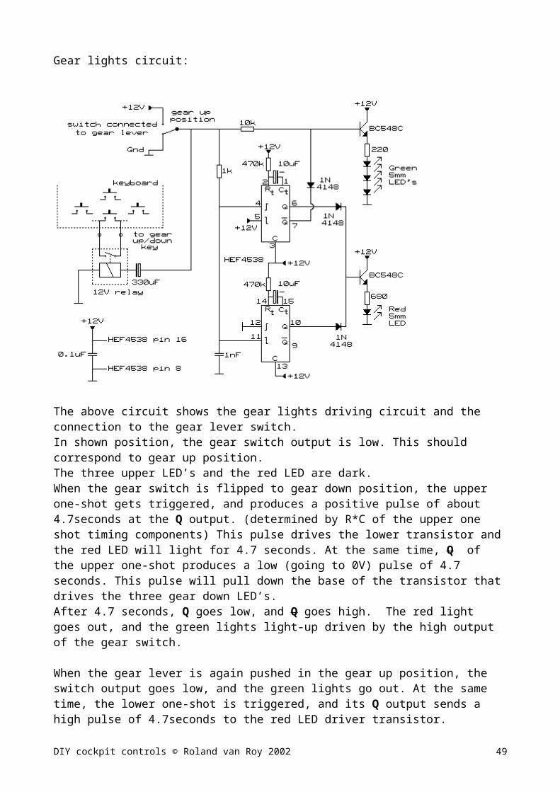
Note on building subwoofers for light aircraft simulation sound system:
One side of my flightsim table top rests on my home-build subwoofer. It measures 750mm high x 600mm deep x 260mm wide. Material is 20mm particle board. The speaker is a 8 inch woofer that I bought in a Taiwan electronics shop for USD 30,-. From acoustics point of view, it makes sense to make the box big. Speaker characteristics together with inner box volume determine the low frequency roll-off point. Too small box volume will limit the low frequency range. For nice deep engine rumble, low frequencies down to 30Hz give great realism. Most multimedia speakers roll-off around 100 – 120 Hz, and the so called “Subwoofers” sold with small PC audio systems may go down to 70Hz or so (if you are lucky), adding lots of distortion along the way. Keep in mind that the difference between 30Hz and 70 Hz is not trivial. A reasonable quality 6” - 8” speaker in a large (100 liter or more), heavy box with 15W power input will outperform any MM subwoofer, unless they are of comparable size.When buying subwoofer speakers, it is hard to get any speaker spec except for power and impedance. If you are able to find more spec details, check for low self resonance frequency (around 25Hz) and low Qts (around 0.45). Power handling is normally not a problem, as 20W (RMS) already gives plenty sound from a large speaker + box combination and will match the sound from the L/R speakers. My box reaches 35Hz, and the sound pressure in the room makes the windows rattle. I used a completely sealed (really airtight) box construction.
DIY cockpit controls © Roland van Roy 2002
T 1
T 2 T 3
T 4V1 V2 V3 V4
GndR-inL-in
+12VGNDSupply
Input
100mm
55m
m
= isolated wire2.54mm pitch experiment boardTop (component) view
Pin 1Pin 17
Pin 1Pin 8
Basic layout of transducer amplifier
T1 … T3: To transducers
T4: To optional subwoofer
49

9. Overview of complete cockpit switch wiring diagram
cockpit light switches Auto pilot switches and LED indicator
Various lever controlled switchesAuto pilot switches with LED
DIY cockpit controls © Roland van Roy 2002 50

Other wiring connection details
Wiring connections of the switches mounted on the yoke.(basically nothing more than extension wires).
Wiring of the Flaps and toe brake switches
Wiring of the two game function keypads
DIY cockpit controls © Roland van Roy 2002 51

Audio and transducer and power supply wiring connections.
Keep in mind that the power supply current capability is mainly necessary to drive the transducers. If the transducer amp is not used, a small 12V / 0.5A supply is sufficient.
The audio splitter can be made from two 3.5mm headphone jacks. Audio splitters may also be available commercially
Keyboard select switch.
By means of a simple 4-pole switch, you can switch between the keyboard in the cockpit controls case and the keyboard for normal (other family members) use. A keyboard cable contains 4 leads. Make sure that you wire the correct leads of each keyboard to the switch terminals.
DIY cockpit controls © Roland van Roy 2002 52

10.Complete cockpit console pictures
These pictures shows how all the building blocks in my setup are placed.
Keyboard connections (noodles?) Throttle section/transducer/gear/switches(Use labels for each wire connection)
DIY cockpit controls © Roland van Roy 2002
Transducer amplifier
Keyboard (upside down)
Engine switch, speedbrake, etc
Toggle to momentary for engine switch, etc.
Elevator potmeter
Yoke column Light
switches
Autopilot switches
Toggle to momentary for light and autopilot
Throttle section transducer.
Throttle/prop/ mixture controls.
Power supply brick
Wiring to toe-brakes, pedal transducer and audio input
Chinese noodles
Trim electronics
USB joystick PCB
Wires & cables to PC (2m long)
53
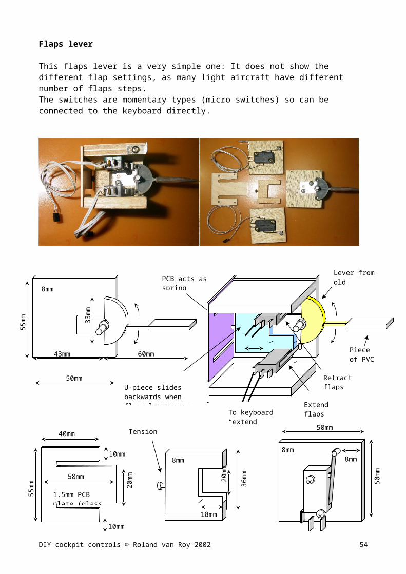
Trim electronics and USB stick PCB Transducer amp connections. (Use thicker wire for the chair transducer)
Engine switch and other levers. Complete front panel (zoom for detail)
Cockpit artwork
For making the cockpit artwork (lettering at the different controls) I used very simple means: In Word I typed a page of text boxes with the text in the right size for each control switch/lever.Then I used a sheet of “Labels for Wordprocessors” (a one-piece A4 sheet label with peel-off back) and printed the textboxes on that sheet. I used simple black and white, but if you have a color printer, the labels can be made more fancy. To make the labels stronger, I taped transparent tape over the printed labels and then cut each label out with a sharp knife.
The attachment shows an example of my cockpit labels.
11.Some notes on using the cockpit controls during the flightsim
Keep in mind that most controls are just linked to the keyboard; there is no feedback between PC and controls concerning the initial positions of the controls and the start-up control settings of the sim. Therefore, it often happens that parking brake, lights and gear positions between sim and hardware do not match. (depending how you start your sim, from parking or at runway / mid-flight.
In Flight Unlimited III this can be easily corrected by pressing Escape (provided in the small keypad) and then returning to the sim by moving one of the levers. The lever movement will only be registered as a “back to sim” keystroke, but will not alter the sim’s cockpit settings. Repeating this sequence for the other mismatched controls will have quickly have you back with fully matching controls.
DIY cockpit controls © Roland van Roy 2002 54

12.Material price indications(Based on Taiwan street price, converted in US$)As mentioned before, I got many parts from the junkyard, where they charge US$ 0.30 per kilo for most stuff. Needless to say, I have a lot of junk at home. (my wife is the forgiving kind)I think I bought for about US$10,- worth of junk for this project. (VCR’s, fax machines, printers….)
Case: Multiplex wood board costs about US$ 15,- for a 1m x 2m boardTabletop covering (for front) and rudders: US$ 3,- per 0.5 m x 1.5m
Yoke:Threaded metal rod and nuts (M15) costs about US$ 3,- Fitting metal tubes around US$ 1,-Potmeter: US$ 0.8 per piece30mm wood board 0.5m x 0.5m for handle: US$ 2,-Tact switches: US$ 1 per 10 piecesMini joy switch: (HAT) US$ 3,- per piece (can’t seem to find them anymore)
Rudder pedalsVarious springs US$ 3,-Patio door wheels US$ 2,- per pedal
Various levers: Toggle switches: US$ 0.5 per piece (small kind) US$ 0.8 for heavy duty type.
Toggle to momentary circuit:Electrolitic capacitor: US$ 0.3 per pieceRelay: US$ 0.8 per pieceExperiment PCB US$ 1,- per piece
Trim circuit:Rotary encoder: US$ 3,- per pieceHEF4538 IC US$ 0.5,- per pieceOpto coupler US$ 0.5 per piece
Gear indicator circuit:HEF4013: US$ 0.5,- per pieceLED : US$ 0.3 per piece
Transducer ciruit: TDA1554Q IC: US$ 6,- per pieceLM358 US$ 0.4,- per piece
Connectors 10 pin to 40 pin US$ 0.2 - US$ 0.5Male pins: US$ 0.4 per 100 pin stack40 lead Ribbon cable: US$ 1,5,- per meter (you need about 3 meter)Shielded stereo wire: US$ 0.5,- per meter (you need about 9 meter)Small PC 2 pin connectors US$ 1,- per 15Gameport connector: US$0.5,- per piece
12V / 4A supply brick or Industry switch mode supply type: US$ 25,- USB joystick US$ 25,-
DIY cockpit controls © Roland van Roy 2002 55
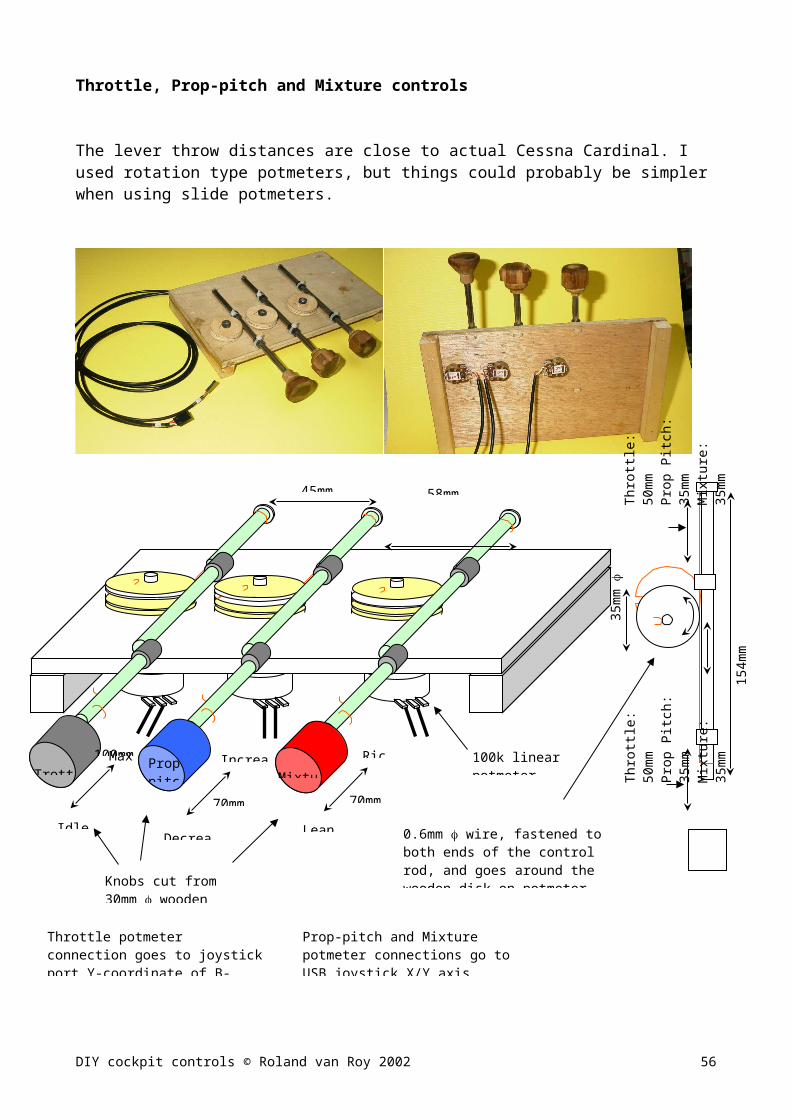
Components from junk: Speakers for transducersOld AT keyboardsEngine switchAll gears, levers, rodsSome equipment switches
Total estimate about US$ 200,- Man hours: a lot! (On and off, I spend about 7 – 8 months)
Keep in mind: Building is half the fun. Happy flying!
Weather and wind modeling is very accurate in FUIII, lots of challenges for any pilot. (FUIII Screenshot provided by Glidernut, the expert in FUIII soaring. Check out his FUIII blackbox videos in the AVsim library)
13.Sources for information One book I can highly recommend for anyone who wants to do electronics (basic to advanced): The Art of Electronics 2nd edition (Horrowitz and Hill) ISBN 0-521-37095-7
The web: do a search on Cockpit Building, and you’ll find lots of interesting sites.
DIY cockpit controls © Roland van Roy 2002 56

14.Attachment:
Text of joykeys.cfg and flt3.cfg
To re-assign joystick key switches and keyboard keys to different functions in FUIII, you have to create a new text file named joykeys.cfg . The readme files that are included in the original FUIII and the patch install include all details concerning the options you have for customizing FUIII.
-----------------;joykeys.cfg
;rudder trimkey_right Rudder_Trim_Right 1key_left Rudder_Trim_Left -1;autopilotkey_t Autopilot_ToggleAprkey_v Autopilot_ToggleNavkey_w Autopilot_LevelWingskey_s Autopilot_HoldAirspeedkey_x Autopilot_HoldHeadingkey_r Autopilot_HoldVerticalSpeedkey_z Autopilot_HoldAltitude;lightkey_\ Toggle_Navigation_Lights;Flapskey_= Flaps_Up -1;enginekey_- Shutdown_Engine;radiokey_home Auto_Tune_Radio;taxikey_end Show_Taxi_Path;pausekey_bs Pause;viewkey_/ Target_Next_Internal 1joy_4 console set_model_density 1 || set_model_density 3 || set_model_density 5joy_3 camera_external----------------------
The flt3.cfg has many options that can be tweaked. Graphics, weather modelling, start-up options, device settingsBelow the section on device settings for my setup
--------------------------------…………opt_master_volume 103mixture_device 2 2prop_pitch_device 2 1
--------------------------------
DIY cockpit controls © Roland van Roy 2002 57

Cockpit artwork (text size matches console dimensions)
DIY cockpit controls © Roland van Roy 2002
APRNAV ALTVER LEV HDGSPD AP
THROTTLEPUSH
INCREASE
PROPPUSH
INCREASE
MIXTUREPUSHRICH
PITOTHT
NAV LT
STRB LT
BEAC LT
TAXILT
LAND LT
PANELLT
CARB HT
GEAR
UP
FLAPS
DOWN
POWER CC TRENGINE
STOP
EXTEND
RETRACT
DEPLOY
STOW
START
PARKING BRAKE
AUTO PILOT
LOCKED
TRANS.
DOWN UP
EXTENDRETRACT
ON
APR NAV ALT VER LEV HDGSPD AP
ON OFF OFF
LEFTRIGHT
STOP DEPLOYSTART
THROTTLEPUSH
INCREASE
PROPPUSH
INCREASE
MIXTUREPUSHRICH
EXTEND
RETRACTSTOW
LOCKED
TRANS.
PITOTHT
NAV LT
STRB LT
BEAC LT
TAXILT
LAND LT
PANELLT
CARB HT
POWER CC TR
SPEED BRAKEPULL DEPLOY
REVERSER DEPLOY
ENGINE
ELEVATOR TRIM
RUDDERTRIM
PARKING BRAKE
GEAR
UP
FLAPS
DOWN STOP DEPLOYSTART
AUTO PILOT
DOWN UP
MRLUP
MRLDOWN
TAXILINE MAP
TAPESTRIP PAUSE ESC YES
AUTOTUNE
CYCLERADIO
ATCCOMM ENTER
PAN ZOOM EXT V DETAIL INT V PCL COMM ENTER 1 2 3 4 5 6 7 8 9
MRLUP
MRLDOWN
TAXILINE MAP
TAPESTRIP PAUSE ESC YES
AUTOTUNE
CYCLERADIO
ATCCOMM ENTER
PAN ZOOM EXT V DETAIL INT V PCL COMM ENTER 1 2 3 4 5 6 7 8 9
APR NAV ALT VER LEV HDGSPD AP LEFTRIGHT
SPEED BRAKEPULL DEPLOY
REVERSER DEPLOY
ELEVATOR TRIM
RUDDERTRIM
ONON OFF OFF
APRNAV ALTVER LEV HDGSPD AP
58


![WELCOME [] · 2013-05-23 · PROJECT REPORT ON TOUCH SWITCH. ... light operated switch & clap switch . ... device with this switch & the switch automatically turns off …](https://static.fdocuments.us/doc/165x107/5b39dfc47f8b9a4b0a8d3c0f/welcome-2013-05-23-project-report-on-touch-switch-light-operated.jpg)


